Installation
Operation
Maintenance
Owner’s Manual
UNDER-BENCH RV HEAT PUMP AIR CONDITIONER
MODEL NO: PYR009AZUDCIPD
IMPORTANT NOTICE:
Please read this manual carefully before installing
or operating your new air conditioning system.
Be sure to save this manual for future reference.
Wireless
Internet
Ready
FCC IDENTIFIER:2ANDL-CB3S
REV082624
304793

I. Operational Instructions.......................................................................1
1. Safety Information................................................................................................................................................1
2. Scope and Purpose of is Manual........................................................................................................................2
3. Model Number and Technical Details Identication.............................................................................................2
4. Description and Illustration of the Machine..........................................................................................................3
5. Best Practices for Optimal Performance.................................................................................................................4
6. Warning and Safety Precautions for A2L Refrigerant..............................................................................................4
7. Description of the Controls...................................................................................................................................5
8. Automatic Mode Operation...................................................................................................................................6
9. Cooling Mode Operation......................................................................................................................................6
10. Dehumidication Mode Operation.....................................................................................................................7
11. Ventilation Mode Operation...............................................................................................................................7
12. Heat Pump Mode Operation..............................................................................................................................8
13. Night Mode Operation........................................................................................................................................8
14. Timer On and Timer O Mode Operation..........................................................................................................9
15. Handling of the Remote Controller...................................................................................................................10
16. Description of the Wall Controller....................................................................................................................10
17. Routine Maintenance........................................................................................................................................11
II. Installation Information....................................................................12
1. Technical Specications.......................................................................................................................................12
2. Getting Started ...................................................................................................................................................13
3. Selecting the Location of Installation...................................................................................................................14
4. Preparation of Floor Openings and Unit Fastening..............................................................................................15
5. Securing the System to the Floor.........................................................................................................................16
6. Fastening the System Into Place...........................................................................................................................17
7. Placement of the Wall ermostat.......................................................................................................................18
8. Recirculation Air Compartment Opening...........................................................................................................19
9. Air Ducting.........................................................................................................................................................19
10. Electrical Hookup..............................................................................................................................................20
11. Simplifed Wiring Diagram................................................................................................................................20
12. Wireless Internet Pairing Process........................................................................................................................21
III. Troubleshooting, Maintenance, Recycling.......................................23
1. Troubleshooting and Diagnosis...........................................................................................................................23
2. Error Codes List..................................................................................................................................................24
3. Exploded Parts Diagram......................................................................................................................................25
4. European Disposal Guidelines.............................................................................................................................26
Table of Contents
INSTRUCTIONAL HANDBOOK
1
Safety Information
OPERATIONAL INSTRUCTIONS
CAUTION - Read Before You Proceed
Read and Understand All Safety Precautions Prior to Installation
For safe operation, it is imperative that the following rules are obeyed:
• is appliance can only be used by children aged 8 years and above,
or by persons with reduced physical, sensory, or mental capabilities,
or persons with lack of experience and knowledge, if they have been
given supervision or instructions concerning usage of the appliance
in a safe way and understand the potential hazards involved.
• Children shall not play with this appliance. Proper cleaning and user
maintenance shall not be done by children without supervision.
• If supply cord is damaged, it must be replaced by the manfucturer,
a certied service agent, or other qualied persons to avoid hazard.
• e applicance shall have a full disconnect switch in the hardwire
conguration in accordance with the national electrical standards.
Failure to abide by the
manufacturer cautions
can result in property
damage, personal
injury and/or death.
Electrical Danger
WARNING - e Manufacturer Is Not Liable For the Following:
•
Units that have sustained damage due to improper installation or have been connected with an incorrect
voltage. Abide by the installation instructions fully and completely to prevent unexpected malfunctions.
Note about Fluorinated Gasses and Operation of the System
1.
is air-conditioning unit contains uorinated gasses. For specic information on the type of gas and the
amount, please refer to the relevant label on the unit itself. Some refrigerants may not exude an odor.
2.
3.
4.
5.
6.
•
Products that have had extra modications, where written consent was not provided by the manfacturer.
•
Product usage in a way that is not the intended purpose as described in this operational instruction manual.
•
Any sort of collateral damage to property or injuring to nearby persons caused by failure of the product.
Installation, service, maintenance, and repair of this unit must be performed by a certied HVAC technician,
or qualied personnel familiar with the risks of handling refrigerant and regulations of air conditioner systems.
Product uninstallation and recycling must be performed by a certied HVAC technician.
e system and/or its internal moving parts should not be touched, poked, or prodded during operation.
Do not use the system near combustible objects or ammable uids. Keep a distance of at least 2 feet from
other nearby appliances. If a re occurs, a proper extinguishing agent, rather than water, must be used.
When the unit is being checked for leaks, proper logging and record-keeping of all checks by certied personnel is
strongly recommended. Refrigerant must never be released into the air, a proper recovery device should be used.
•
Improperly grounded products. e product must be properly grounded at the time of installation, else
electrical shock may occur.
•
Incorrect conguration of drainage. Install drainage channels according to the instructions in this manual.
Improper drainage may cause water damage to your vehicle and property.
2
Scope and Purpose of is Manual
Model Number and Technical Details Identication
OPERATIONAL INSTRUCTIONS
is manual has been specically compiled by the manufacturer and is an essential
component of the machine. e information contained within can guarantee
proper usage of the machine, if observed and followed carefully.
Sections I and III are intended to provide helpful instructions and knowledge to
the end user. Section II is intended to intruct the installer, who should be a person
that possesses expert knowledge and experience in this eld of work.
Where applicable, some portions of text may be accompanied by certain symbols,
that of which can be understood by referencing the below table:
is symbol indicates a potential source of danger.
is symbol indicates useful information or a helpful tip.
is symbol indicates information on being environmentally friendly.
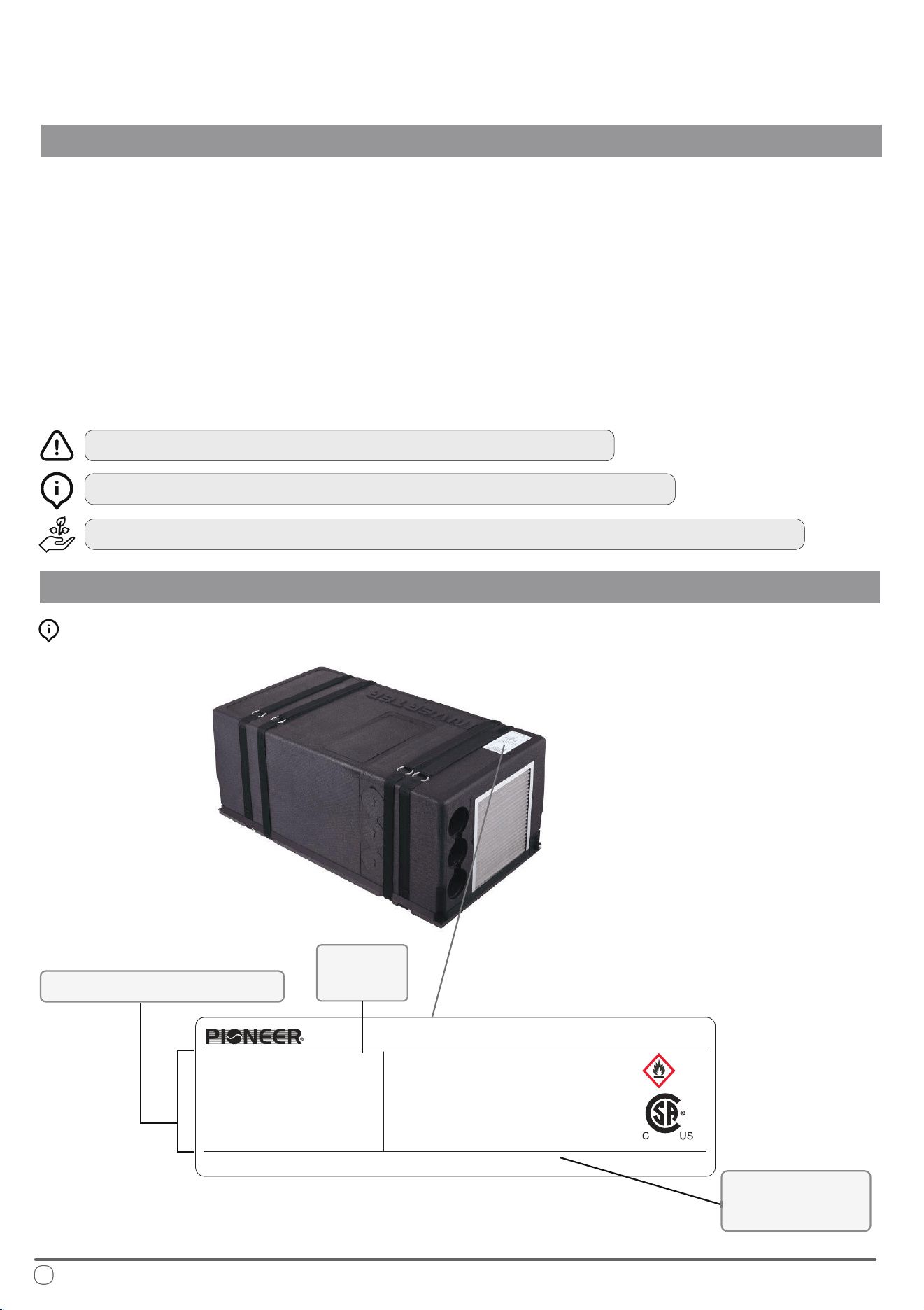
Interpreting the Rating Label:
Technical Specications
Model
Number
Supplier
Information
Date of Manufacture: See barcode
MADE IN CHINA
8.6A
A2L
R32
390 g/13.75 oz
IPX5
6 MPa/870 PSIG
57.6 lbs
28.9x15.95x11.65 inch
304793
PYR009AZUDCIPD
115V/60Hz
10000Btu/h
9500Btu/h
8.6A
6.9A
675
1/8HP
Model:
Power :
Cooling
Capacity :
Heating Capacity :
Max current for Cooling :
Max current for Heating :
Rated input current of the power
conversion Equipment:
Indoor Fan Motor:
Under-Bench Air Conditioner
Global Warming Potential:
Refrigerant :
Charge :
Waterproof(For final installation):
Maximum allowable Pressure(High Side):
Weight :
Dimensions(LxWxH):
PARKER DAVIS HVAC INTERNATIONAL
Miami, FL - www.pdhvac.com - (800)-675-7410
3
Description and Illustration of the Machine
OPERATIONAL INSTRUCTIONS
e purpose of this machine is to provide greater control of the air temperature
within the vehicle that it is installed (such as motor homes, caravans, recreational
vehicles, etc.). When the ambient outdoor temperature is hot and humid, it can
supply the vehicle with cool and dehumidied air via the refrigeration cycle.
It can also run this process in reverse, to supply heated air into the vehicle, whether
as a supplement, or replacement for the vehicle’s original heating system. In both
instances, the setting of the desired air temperature is congurable by the user.
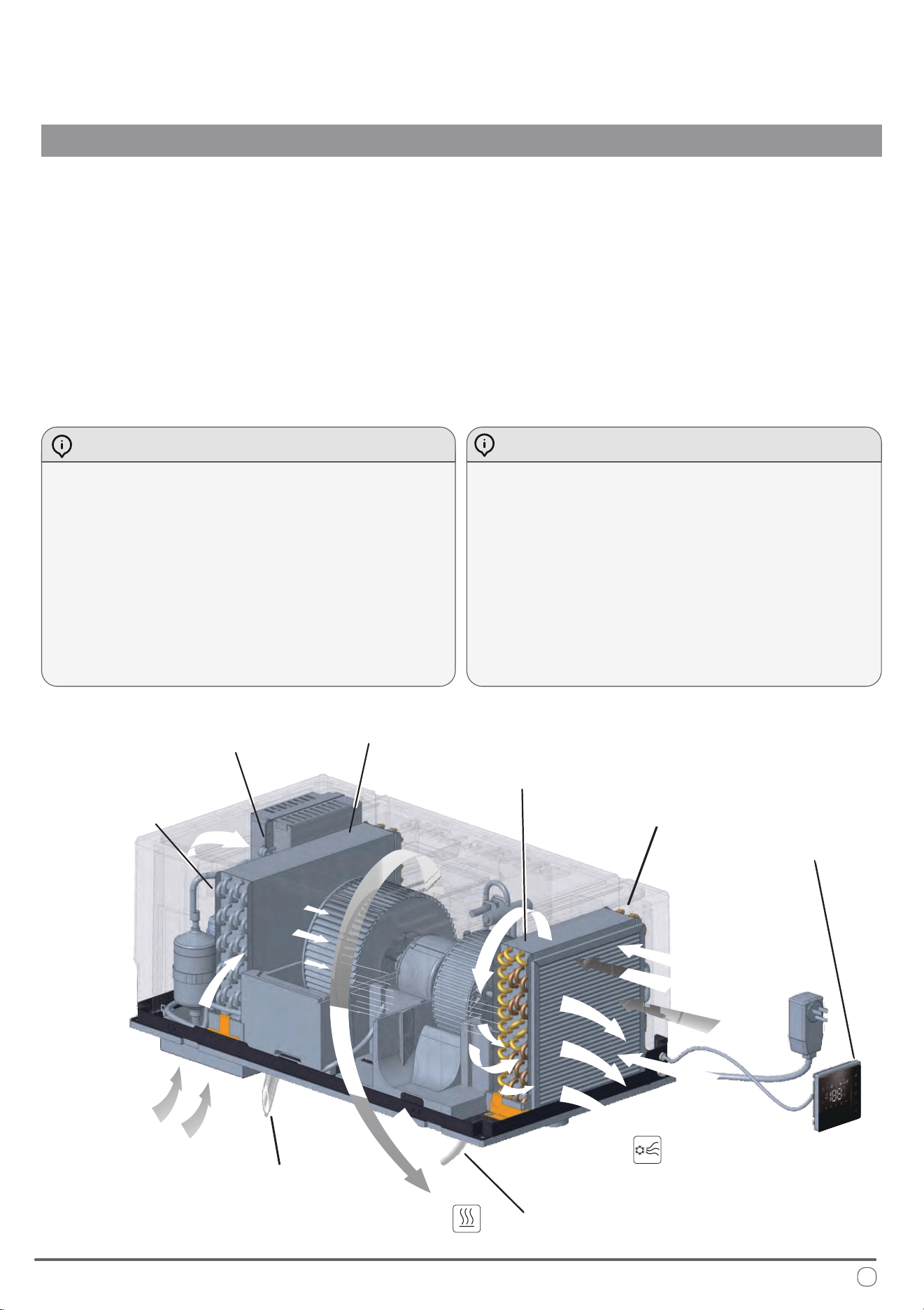
Cooling Mode - Description of Operation Heating Mode - Description of Operation
By changing physical state from liquid to gas, the
refrigerant heats or cools the components through
which it passes. e air that is drawn into the system
(the “return air”) by the fan blower (C) ows through
the evaporator which has been made signcantly cold.
e air then comes out cooled and removed of
humidity (the “supply air”).
is process repeated continuously over a long period
of time leads to a reduction in the air temperature
and humidity levels inside the vehicle.
e method of heating is quite similar to that of
cooling, however the process occurs in reverse.
e refrigeration cycle is reversed by the 4-way valve
switching over (F). e internal coil becomes the
condenser rather than the evaporator, thereby heating
the air that passes through it.
is process takes more standby time as the internal
coil spends a few minutes heating up to begin working,
in addition to periodic defrost cycles from the machine.
e system is composed of: (A) Compressor, (B) Condenser, (D) Evaporator, (F) 4-Way Valve
and Pressurized Refrigerant R32.
Condensate Drain
Condensate Drain
(in Heating Mode)
Wall Controller
Evaporator (D)
Fan Blower (C)
Condenser (B)
Compressor (A)
4-Way Valve (F)
Flow of air introduced
from outside
Hot air
expelled
Treated air
reintroduced
into the vehicle
Flow of air
drawn from
inside the
vehicle
4
Best Practices for Optimal Performance
OPERATIONAL INSTRUCTIONS
For best results, the following tips are given in order to improve the output and
eciency of the machine:
Increase the vehicle’s insulation amount by sealing o openings and covering
glass surfaces with reective or blackout curtains.
When running the machine, select the desired temperature and fan speed and
ensure that the air vents are oriented in a suitable and proper direction.
Avoid the frequent opening of doors and/or windows when not necessary.
To prevent mechanical malfunctions and minimize risk of personal injury, ensure
that the following precautions are abided by:
Avoid obstruction of the ventiled air inlet. Do not cover with cloth, paper, etc.
Do not put hands or insert ngers into any of the machine’s openings.
Do not spray water into or onto the surface of the machine.
Keep ammable substances and objects 3 feet or more away from the machine.
Clean the machine’s air lters periodically.
Warnings and Safety Precautions for A2L Refrigerant
is appliance uses A2L refrigerant, which is classied as mildly ammable. It is critical to follow these safety precautions to minimize
the risk of re or explosion.
Handling and Installation:
• Only qualied personnel should handle A2L refrigerant. Improper handling can cause injury or damage.
• Before servicing, check for ignition sources and ensure proper ventilation. Use a suitable leak detector to conrm the area is safe.
• Ensure all electrical components are rated for A2L refrigerant and avoid any sources of ignition during installation or service.
• When charging the system, ensure proper grounding and secure connections. Avoid overlling the system.
Leak Detection and Repair:
• If a leak is suspected, do not use open ames or spark-generating tools. Use appropriate electronic leak detectors.
• Evacuate and ventilate the area immediately if a leak is found. Repair leaks only when the area is safe.
• Keep a re extinguisher rated for ammable materials nearby when working with A2L refrigerants.
Decommissioning and Disposal:
• Recover all refrigerant and purge the system with inert gas before disassembly.
• Dispose of refrigerant according to regulations and do not vent it into the atmosphere.
• Clearly label equipment containing A2L refrigerant and ensure all safety information is visible.
Adhering to these guidelines ensures safe handling and use of A2L refrigerant, preventing injury, damage, or environmental harm.
A2L
5
Description of the Controls
OPERATIONAL INSTRUCTIONS
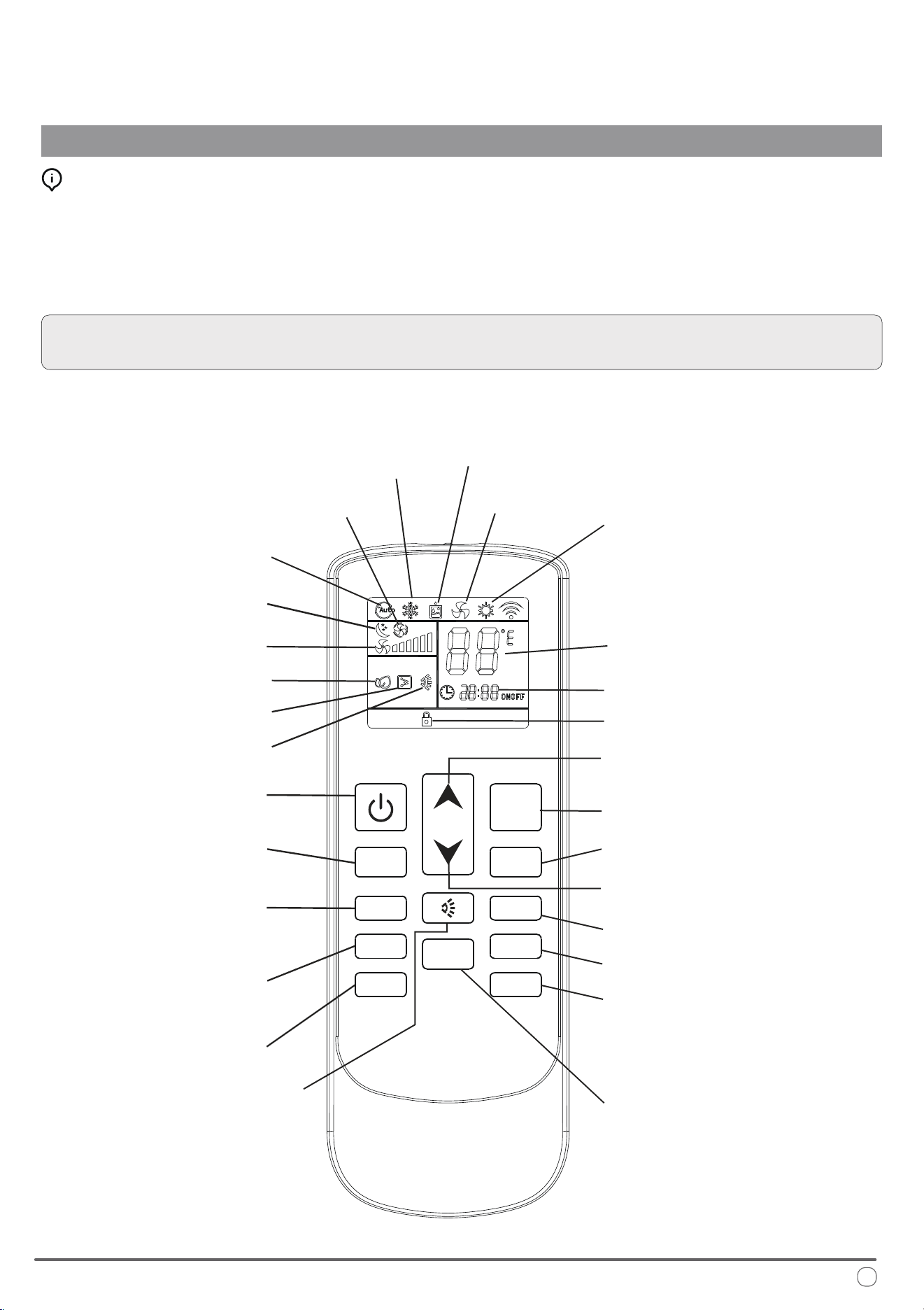
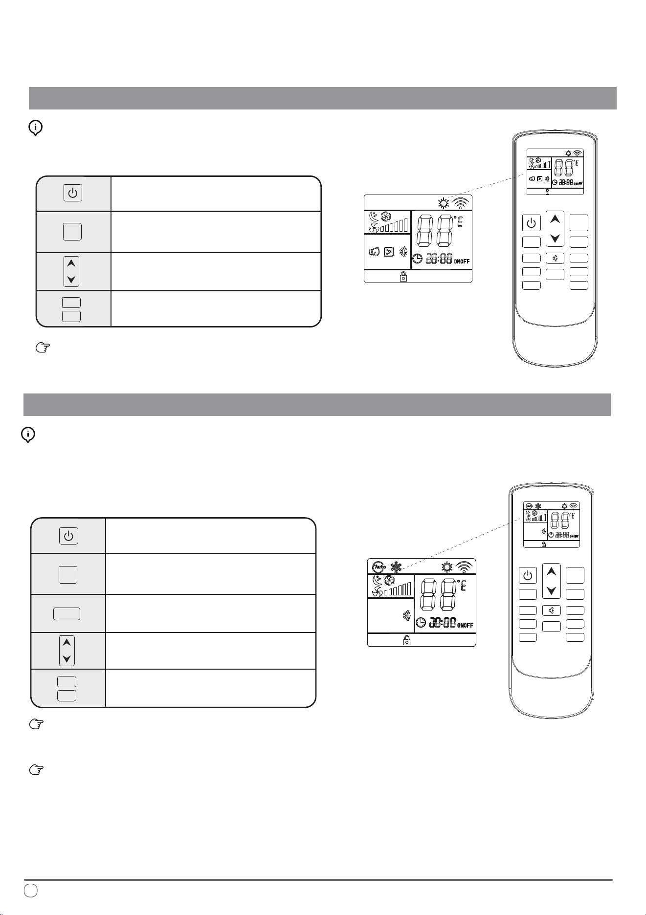
Selecting the Functional Mode:
Press the MODE button to cycle between the available states on the machine.
After two seconds have elapsed, the system will conrm the selection with an
audible beep from the machine’s speaker. Always point the remote controller
toward the wall pad when sending commands to ensure the best reception.
NOTE: When rst switching on the system, the machine will stay in standby
mode for a few minutes before the compressor begins operating.
Dehumidication
(Dry) Mode
Ventilation
Mode
Night
Mode
Automatic
Mode
Change Mode
Temperature
Selection (+)
Temperature
Selection (-)
Heat Pump Mode
Clock
Cooling Mode
Set Point
Fan Speed
On/O
Timer On/O
Clock Conguration
Toggle Celsius
or Fahrenheit
(No Current
Function)
(No Current
Function)
(No Current
Function)
FAN- FAN+
MODE
HEATER SLEEP
CLOCK TIMER
LOCK
LIGHT
0
C /
0
F
Lock Indicator
Auto Fan
Lock Toggle
Light
Electrical Heat
Airow Direction
Fan Speed (+)
Fan Speed (-)
Sleep Mode
6
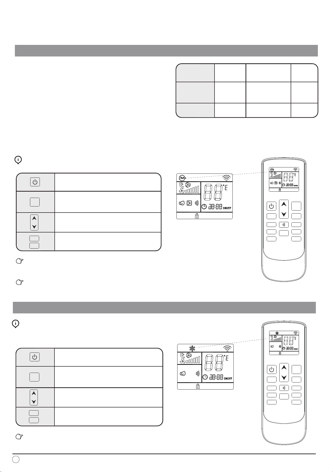
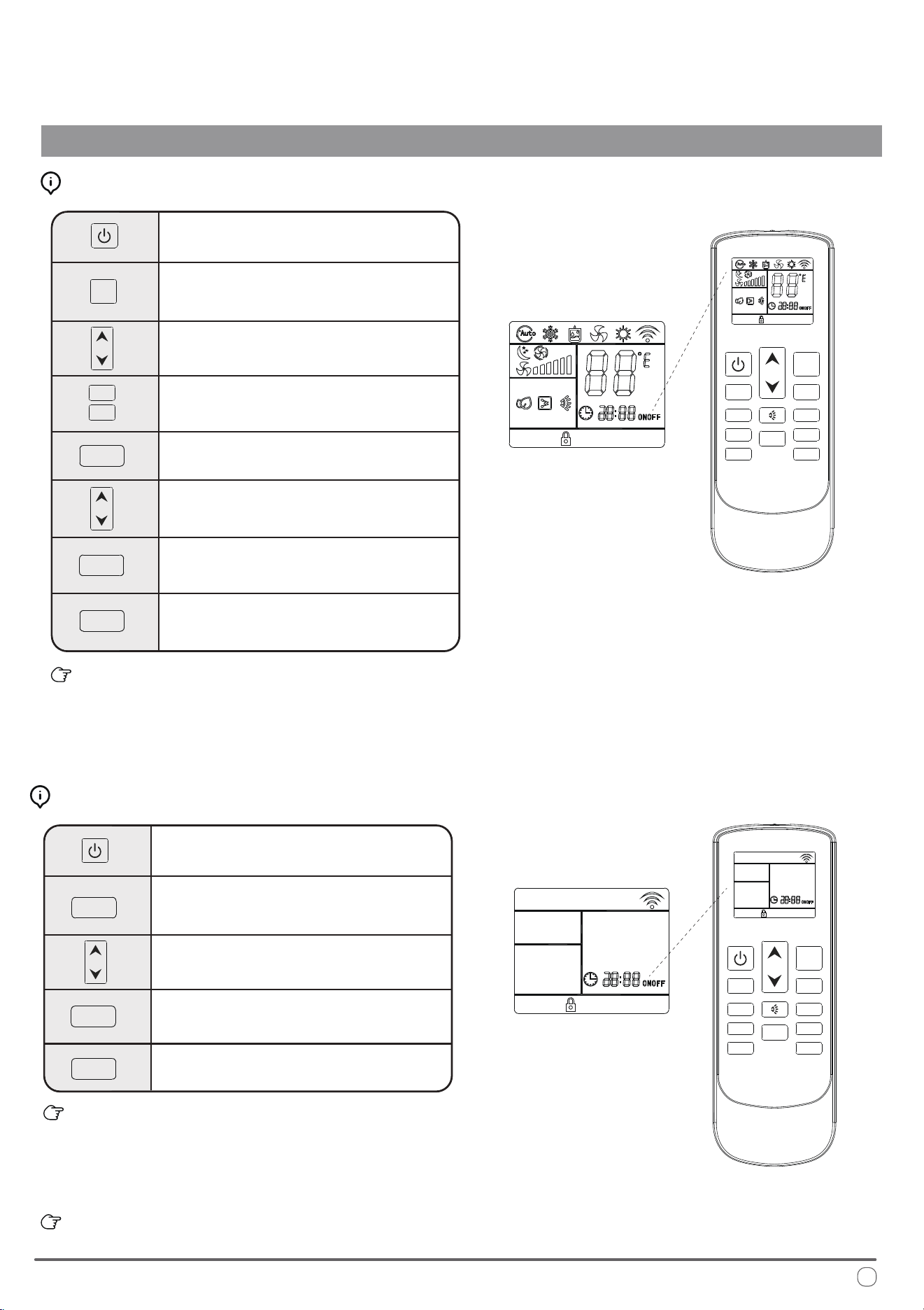
Automatic Mode Operation
OPERATIONAL INSTRUCTIONS
In AUTO mode, the system manages the
compressor, heat pump, and fan speeds
entirely autonomously by comparing the
set temperature with the current internal
temperature as given in the following table:
T ≤ 68°F
T ≥ 77°F
68°F < T < 77°F
Internal
Temperature
Operating
Mode
Set Point
Heating,
Ventilation
Dehumidication,
Ventilation
Cooling
77°F
68°F
72°F
On the AUTO speed setting the ventilation speed is set according to the dierence
in temperature between the set point and the current ambient temperature.
Automatic Mode Button Control:
Press the On/O button to switch the
machine on or o
Press the Change Mode button to
select AUTO mode
e temperature selection buttons are
disabled in this mode
Press the fan speed buttons to select low,
medium, high, or automatic fan speed
Set temperature is selected based on the conditions given in
the set point table on this page.
e selected conguration will be retained in the system’s
memory when it is switched on again next.
Cooling Mode Operation
Press the On/O button to switch the
machine on or o
Press the Change Mode button to
select COOL mode
Use the temperature selection buttons to
select a set point between 64 and 86°F.
Press the fan speed button to select low,
medium, high, or automatic fan speed
e selected conguration will be retained in the system’s
memory when it is switched on again next.
Cooling Mode Button Control:
See page 3 for an explanation of Cooling Mode functionality.
FAN-
FAN-
FAN+
FAN+
MODE
MODE
HEATER SLEEP
CLOCK TIMER
LOCK
LIGHT
FAN-
FAN+
MODE
0
C /
0
F
FAN- FAN+
MODE
HEATER SLEEP
CLOCK TIMER
LOCK
LIGHT
0
C /
0
F
7
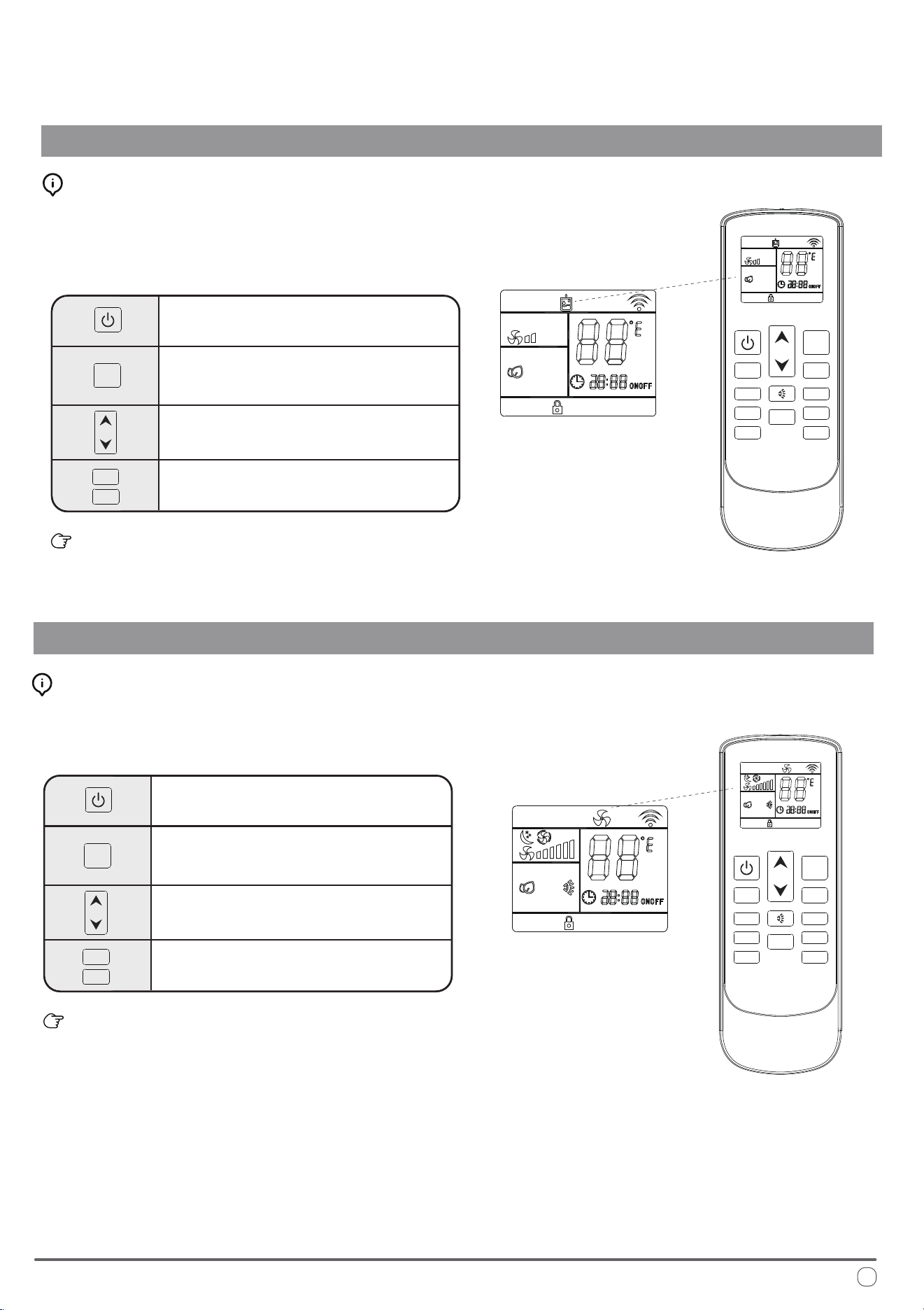
Dehudication Mode Operation
OPERATIONAL INSTRUCTIONS
Press the On/O button to switch the
machine on or o
Press the Change Mode button to
select DEHUDIFICATION mode
Use the temperature selection buttons to
select a set point between 64 and 86°F.
Fan speed selection button is disabled
in this mode.
e selected conguration will be retained in the system’s
memory when it is switched on again next.
Dehumidication Mode Button Control:
Ventilation Mode Operation
Press the On/O button to switch the
machine on or o
Press the Change Mode button to
select VENTILATION mode
Use the temperature selection buttons to
select a set point between 64 and 86°F.
Press the fan speed button to select low,
medium, high, or automatic fan speed
e selected conguration will be retained in the system’s
memory when it is switched on again next.
Ventilation Mode Button Control:
Fan-only mode is used to set the system to use only air ventilation
and no heating or cooling.
Dehumidication mode is a limited function that can help reduce
the humidity/moisture of the room. However, this system is not
intended for use as a dedicated dehumidier and so this mode
should not be left running for very long periods of time.
FAN-
FAN+
MODE
FAN-
FAN+
MODE
FAN- FAN+
MODE
HEATER SLEEP
CLOCK
TIMER
LOCK
LIGHT
0
C /
0
F
FAN- FAN+
MODE
HEATER SLEEP
CLOCK
TIMER
LOCK
LIGHT
0
C /
0
F
8
Heat Pump Mode
OPERATIONAL INSTRUCTIONS
Press the On/O button to switch the
machine on or o
Press the Change Mode button to
select HEAT PUMP mode
Use the temperature selection buttons to
select a set point between 64 and 86°F
Press the fan speed button to select low,
medium, high, or automatic speed
e selected conguration will be retained in the system’s
memory when it is switched on again next.
Heating Mode Button Control:
Night Mode Operation
Press the On/O button to switch the
machine on or o
Press the Change Mode button to
select the desired operation mode
Use the temperature selection buttons to
select a set point between 64 and 86°F.
e system automatically keeps the fan
speed to low when using this mode
Press the night mode button to turn
this feature on or o
e selected conguration will be retained in the system’s
memory when it is switched on again next.
is mode sets the ventilation on low speed therefore it is
not possible to switch to the other available options.
Night Mode Button Control:
See page 3 for an explanation of Heating Mode functionality.
Night mode is generally meant for periods of lower cooling
requirements, such as during typical sleeping hours. is mode
will result in decreased energy use, and can only be activated via
remote control.
FAN-
FAN+
FAN-
FAN+
MODE
MODE
FAN- FAN+
MODE
HEATER SLEEP
CLOCK TIMER
LOCK
LIGHT
0
C /
0
F
FAN- FAN+
MODE
HEATER SLEEP
SLEEP
CLOCK TIMER
LOCK
LIGHT
0
C /
0
F
9
OPERATIONAL INSTRUCTIONS
Timer On and Timer O Mode Operation
Press the On/O button to switch the
machine on
Press the Change Mode button to
select the desired operation mode
Use the temperature selection buttons to
select a set point between 64 and 86°F.
Press the fan speed button to select low,
medium, high, or automatic fan speed
Press the Timer button to set the time at
which the system turns itself o
Use the temperature selection buttons to
modify the time value selection
When the Timer O button is rst pressed, the symbol on the
display will be ashing to signify the switch-o feature is being
set. Pressing it once more will conrm the data entered, and the
icon will remain solid to indicate that Timer O is set. Pressing
it a third time deactivates the Timer O function.
How to Congure the Timer O Feature:
e system must currently be o to
congure the Timer On function
Press the Timer button to set the time
at which the system will come on
Use the temperature selection buttons to
modify the time value selection
When the Timer button is rst pressed, the symbol on the
display will be ashing to signify the switch-o feature is being
set. Pressing it once more will conrm the data entered, and the
icon will remain solid to indicate that Timer O is set. Pressing
it a third time deactivates the Timer O function.
e system starts in AUTO mode at time of Timer On activation.
How to Congure the Timer On Feature:
Press the Timer button to conrm
the selections entered
Pressing the Timer button once more
will deactivate the feature
Press the Timer button once more to
conrm the selections entered
Pressing the Timer button for a third
time will deactivate the feature
FAN-
FAN+
MODE
FAN- FAN+
MODE
HEATER SLEEP
CLOCK TIMER
TIMER
TIMER
TIMER
TIMER
TIMER
TIMER
LOCK LIGHT
0
C /
0
F
FAN- FAN+
MODE
HEATER SLEEP
CLOCK
TIMER
LOCK
LIGHT
0
C /
0
F
10
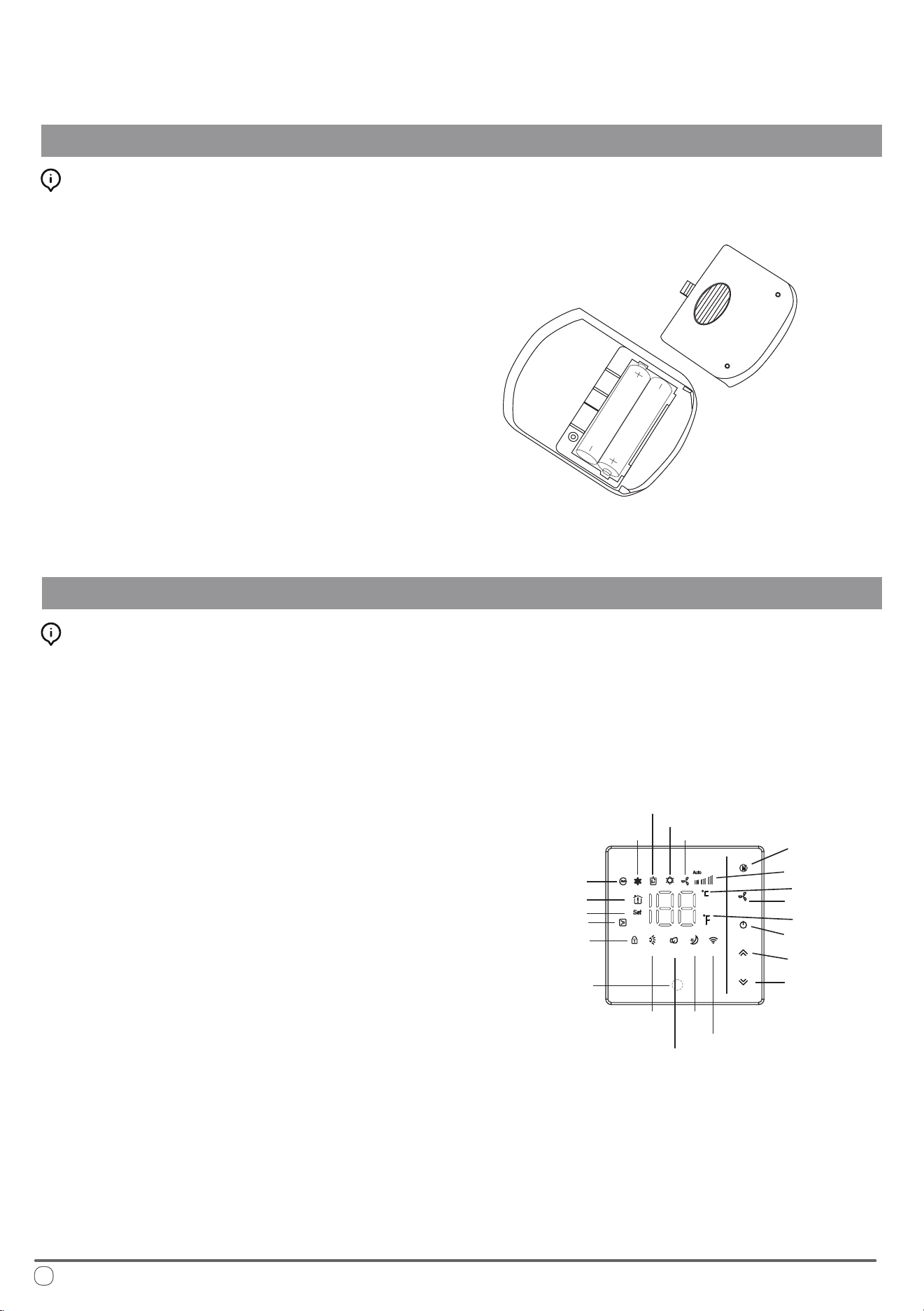
Handling the Remote Controller
OPERATIONAL INSTRUCTIONS
Installing/Changing the Remote Controller Batteries:
1. Remove the rear battery cover
2. If there are already batteries installed, remove
them and insert two fresh AAA size batteries,
ensuring to pay attention to the direction
of their polarities (+/-).
3. Slide the rear battery cover of the remote
back into place.
4. Check that the remote works properly by
pressing the ON button. If on pressing the
ON button no icon appears on the display,
re-install the batteries and conrm that they
are new and have been placed in the correct
orientation
5. e system is now ready to be controlled.
1. MODE Button - Use this button change the
operating modes of the system.
2. FAN Button - Use this button to select the
desired fan speed (auto/high/med/low).
3. ON/OFF Button - Use this button to switch
the system On or O. It will start using the
memory of the previous settings.
4. Up/Down Buttons - Use these two buttons
to congure the desired temperature.
5. Functional LED Display - is will tell you
the current set point temperature setting.
After 10 seconds have elapsed, this will begin
showing the current room temperature. Once
1 minute has elapsed, the display will turn o.
6. Child Lock Button (Up/Down)- Press and
hold the up/down keys to open the child lock
state. e system will then block any input.
7. Wireless Internet Connection (down button
when O) - Press and hold the Down key
with the system o to enter pairing mode.
Description of the Wall Controller
Introduction to the Wall Controller Buttons:
Wireless Internet
Cool mode
Dehumidify mode
Heat pump mode
Fan mode
Mode
Fan speed
Fan
Degree °C
Degree °F
Up
Power on/o
Down
(Wireless
Internet pairing)
Sleep
Lighting
(standby)
Air Swing
Infrared
receiver
Room Temp.
Set Temp.
Electric auxiliary heat
Lock
Auto mode
11
Routine Maintenance
OPERATIONAL INSTRUCTIONS
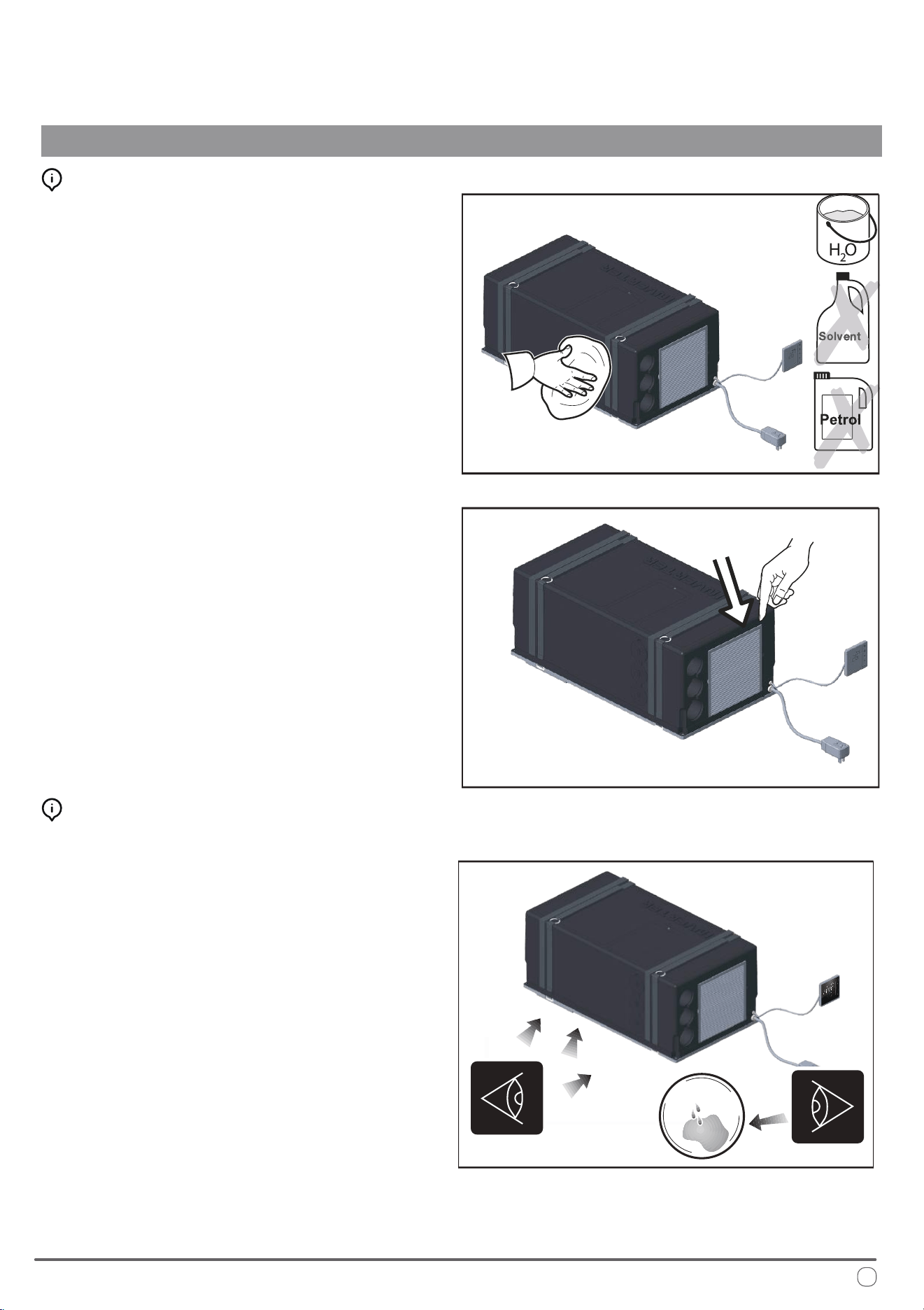
Periodic Cleaning Methods:
Using a soft and moist cloth, wipe down the surface
area of the machine periodically in order to remove
dust. Use clean water or a non-aggresive detergent if
necessary. Do not use petrol or solvents to clean the
machine. Repeat this process every season.
Remove the air lters and wash gently by hand with a
detergent solution, allowing it to dry before inserting
back into place. Repeat this process every 30-45 days.
If an optional active carbon lter is installed, it is
advised to replace them yearly.
Checking Best Practices:
Periodically inspect the system, particularly the points
of drainage, as well as the air intake points.
Ensure that the system is able to drain succesfully. If
there are any sort of clogs, clear the blockage before
continuing to operate the system.
Conrm that there are no obstructions in the oor
openings. For best performance, it is important that
the condenser-side return air can enter and exit the
system without any restrictions.
12
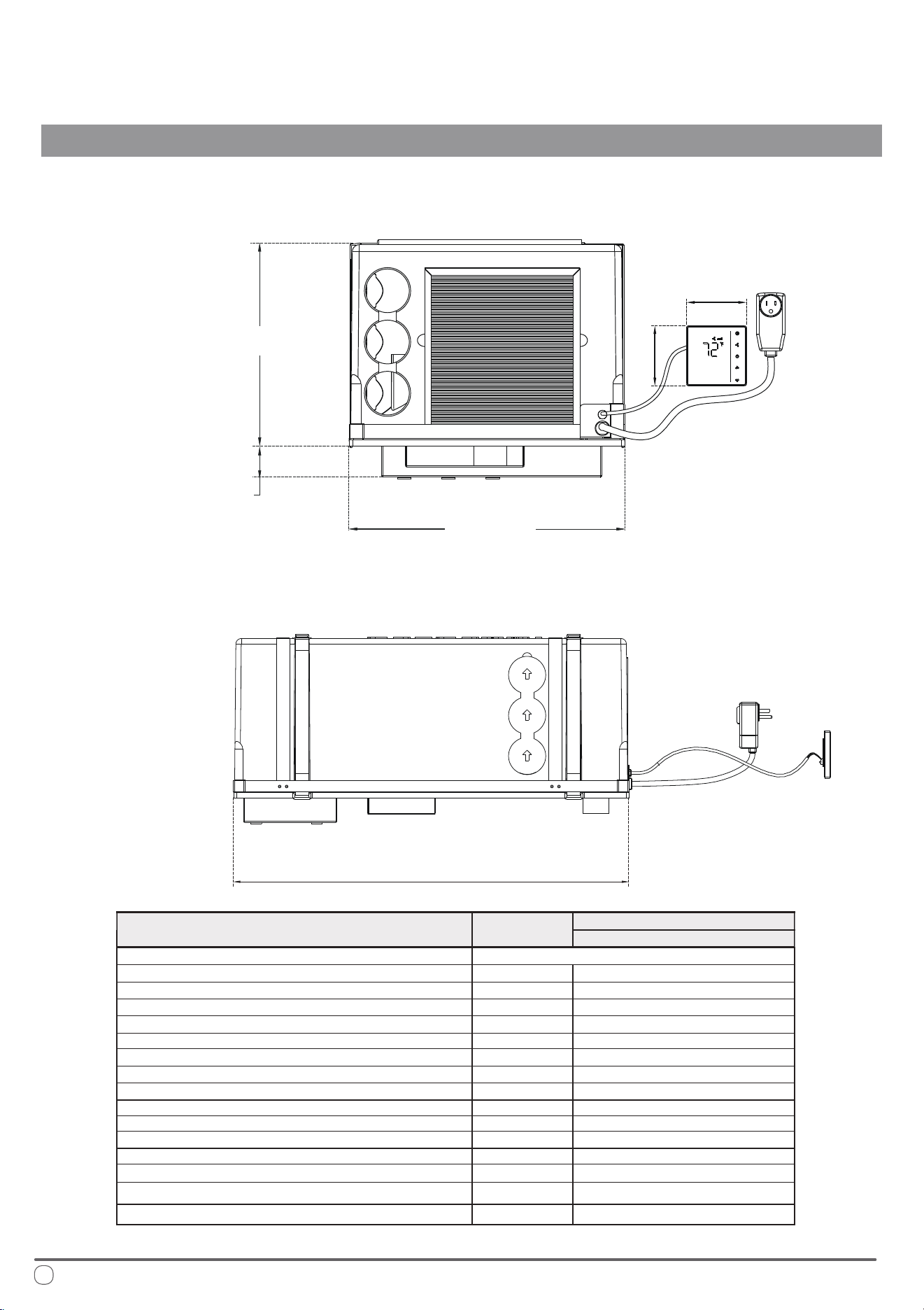
Technical Specications
INSTALLATION INSTRUCTIONS
*All measurements in inches
28” - 7/8
Front View
Side View
11” - 5/8
15” -15/16
1” - 3/4
3” - 1/2
3” - 1/2
Description
Unit of
Measurement
Model Number
PYR009AZUDCIPD
Cooling Capacity
Refrigerant Type/Amount
Maximum Cooling Operational Consumption
Maximum Heating Operational Consumption
Breakaway Current
Additional Heating Element
Electricity Supply
Protection Class
Weight
Ventilation
Maximum Treated Air Volume
Global Warming Potential
Cooling Operating Temperature
Heating Operating Temperature
Heating Capacity
Maximum Volume (Recommended with Insulated Walls)
BTU/hour
See System Nameplate
Amps
Amps
Amps
Watts
IP
CFM
lbs
Volts - Hertz
Speed No.
GWP
Outdoor/Indoor
Outdoor/Indoor
ft
3
BTU/hour
10000
8.6
6.9
20 (150ms)
/
115 - 60
X5
206
57.6
3
675
from 63
o
F to 109
o
F/from 63
o
F to 90
o
F
1060
9500
from 28
o
F to 75
o
F/from 28
o
F to 81
o
F
13
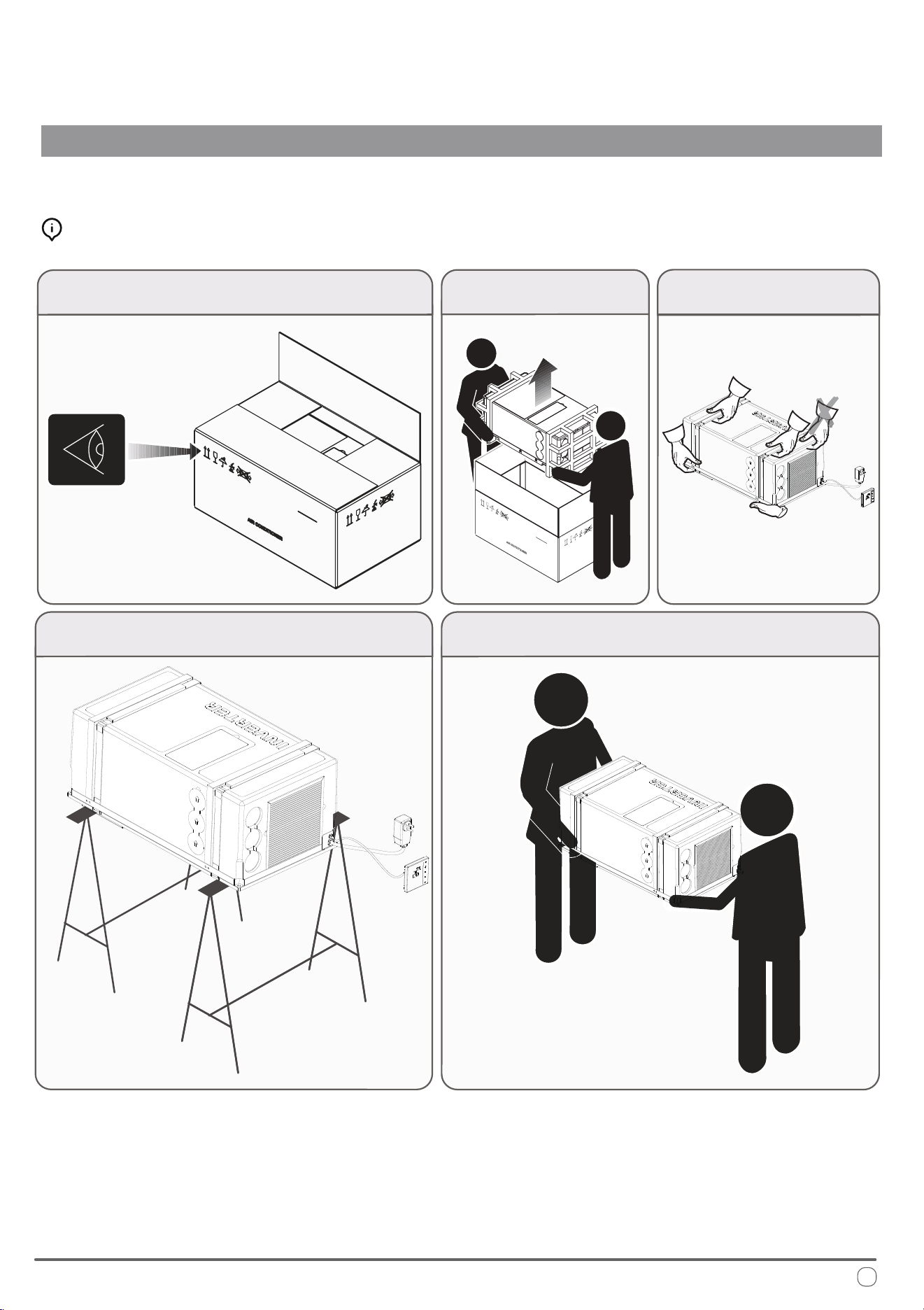
Getting Started
INSTALLATION INSTRUCTIONS
Unpacking and Handling the System:
Installation should only be performed by those with sucient technical knowledge. In addition, the proper tools and equipment should
be used for the installation process, to ensure the safety of themselves and those nearby.
Observe and follow any special instructions or warnings present
on the outer packaging before attempting to handle the system.
Using equal force on both sides,
lift the machine out of the box.
Lift the machine by using only the
handles or the belts on the base.
When resting the system on a surface, assure to distribute the
weight of the machine by supporting it on both sides equally.
Seek the help of an additional person to assist in transferring the system
to the nal place of installation, being sure to do so slowly and carefully.
14
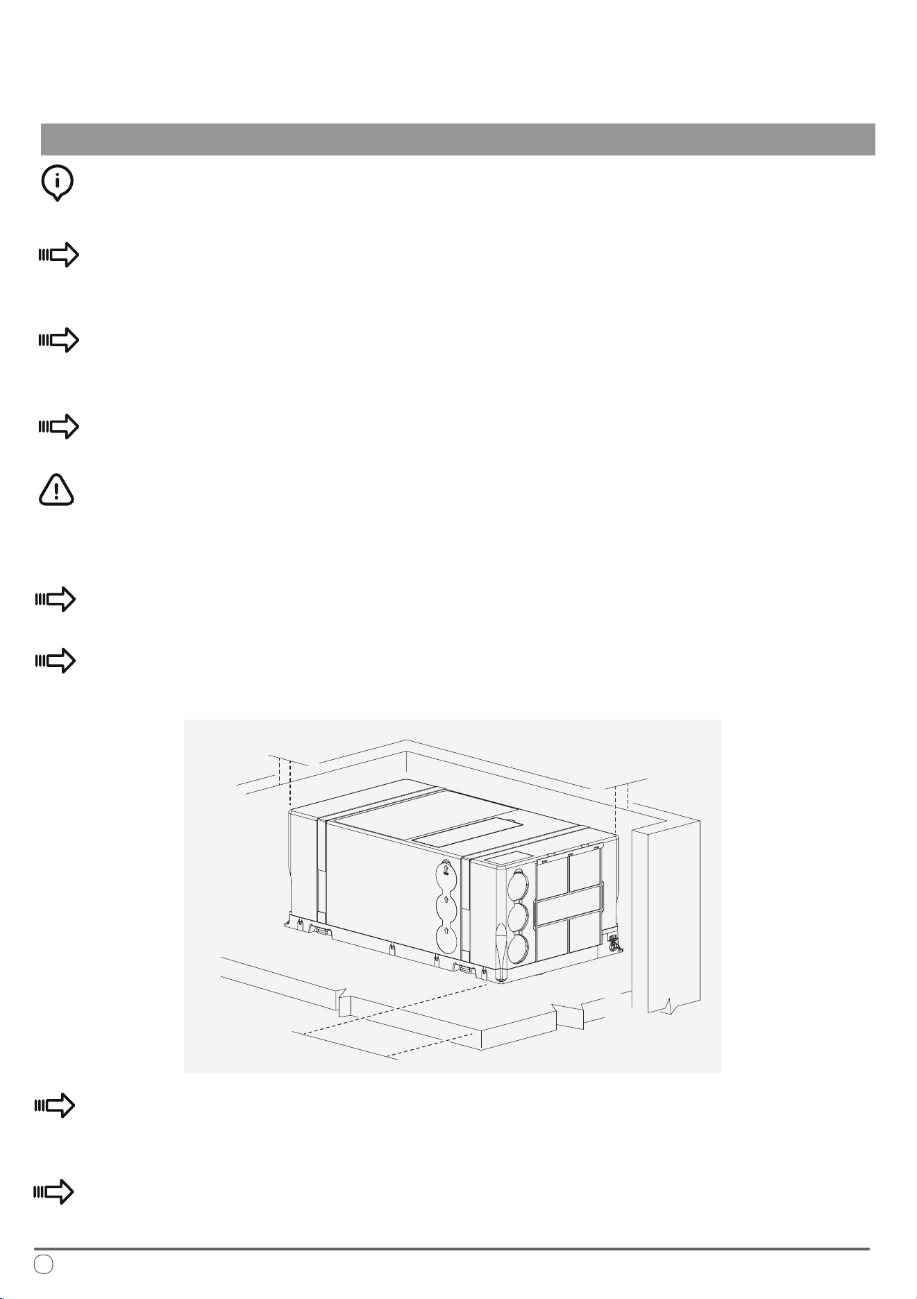
Selecting the Location of Installation
INSTALLATION INSTRUCTIONS
In order for the machine to properly provide uniform climate control in the vehicle,
it should be installed as close to the center as possible, inside a housing/compartment.
Position the machine so as to ensure ease of access, and facillitation of both
installation and disassembly.
Place the template used for assembly within the compartment intended for
installation and verify the available space for the needed openings in the oor.
Avoid the frequent opening of doors and/or windows when not necessary.
In order to minimize transmission of noise and/or vibration during operation, the
machine must have a minimum clearance of 1 inch away from walls and ttings
on either side.
e machine must be installed on the oor, and as horizontally level as possible.
To allow for ease of lter replacement, keep a distance of 8 inches from the
front of the machine and the interior wall of the compartment.
If incorporating any external compartments (such as false bottoms), the air that
is to be treated must be drawn in from the vehicle’s passenger compartment.
Drawing in air from outside can negatively impact the performance of the
system signicantly.
8 inches
1 inch
1 inch
15
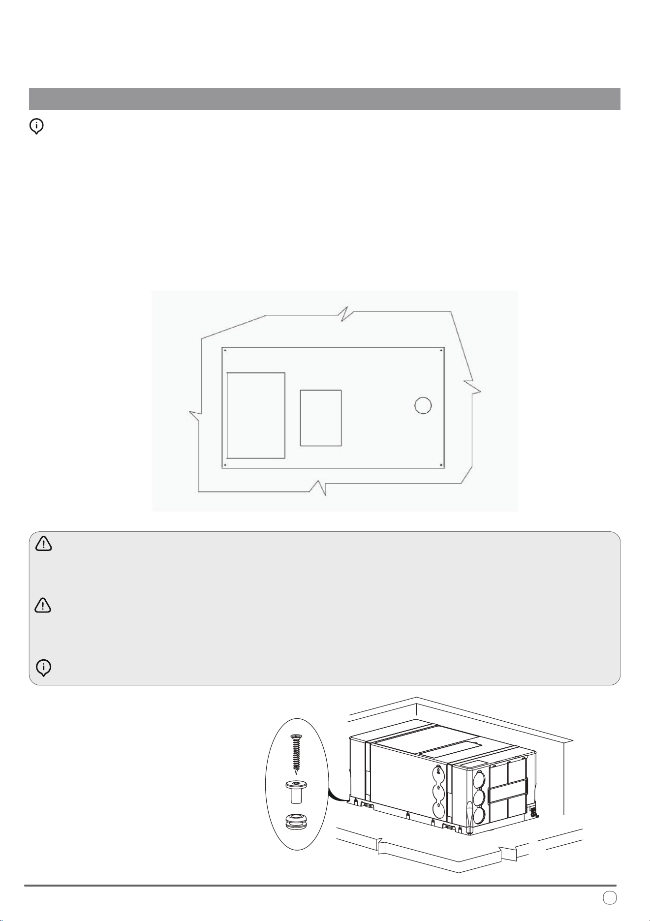
Preparation of Floor Openings and Unit Fastening
INSTALLATION INSTRUCTIONS
Clearances and Procedure for Securing the System:
Installation of the machine involves creating openings in the oor. ese openings
must not be covered or obstructed by parts of the chassis frame or similar xtures.
It is also important to block the openings from splashes coming from the wheels,
using a splash guard or something similar if necessary.
Take special care to ensure a gap of at least 1 inch is left between the machine and
its adjacent walls. Use the provided kit to secure the machine to the interior oor.
e machine must be installed completely level. ere is a maximum angle of
10° to prevent condensation leakage.
Prior to cutting the holes, verify that there are no cables, gas pipes, or parts of
the chassis frame or similar xtures underneath or hidden below.
Seal the machined surfaces of the oor openings with water-repellant solutions.
Bottom View
e provided kit is used
to secure the machine to
the interior oor.
*All measurements
in inches
16
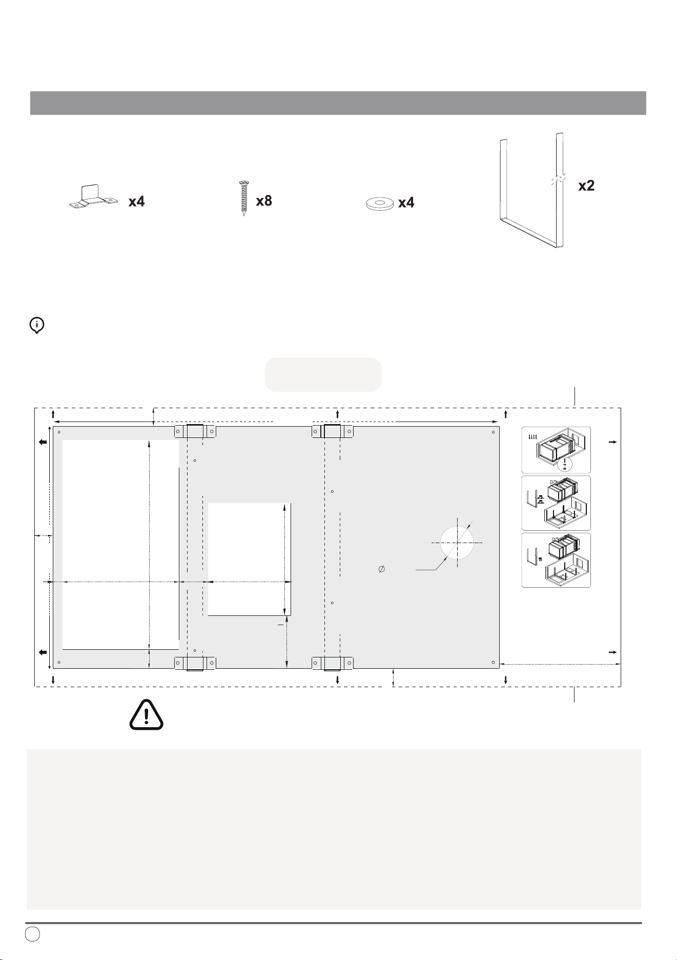
Securing the System to the Floor
INSTALLATION INSTRUCTIONS
e following pieces of hardware (included)
will be used to x the system to the oor:
ere are three dierent methods of xing the system to the oor using dierent
combinations of the above hardware, depending on preference, explained later.
1. Use the included template as depicted above to mark the locations of the openings.
2. Carefully cut out the openings at the bottom using a reciprocating saw or other cutting tool.
3. Drill out the necessary 2”-1/4 diameter condensate drainage hole using a hole saw.
4. Mark the locations of the fastening screws and the brackets using the above template
after selecting the desired method of xing the system to the oor.
Preparing the Bottom Openings (Top View):
Fastener Bracket
Screws
Washer
Belt
1”-7/8
3” -1/16
2” - 1/4
DRAIN HOLE
FIXING HOLE
(Method 1)
FIXING HOLE
(Method 1)
FIXING HOLE
(Method 1)
FIXING HOLE
(Method 1)
FRONT
FIXING HOLE
(Method 2)
FIXING HOLE
(Method 2)
FIXING HOLE
(Method 2)
FIXING HOLE
(Method 2)
FIXINGHOLE
(Method 3)
FIXINGHOLE
(Method 3)
FIXING HOLE
(Method 3)
FIXING HOLE
(Method 3)
INLET
13” - 1/8
7” -1/4
5” - 3/8
7” - 1/4
OUTLET
28” - 7/8
15” - 7/8
KEEP AT LEAST 1 INCH BETWEEN THE
UNIT AND THE SURROUNDING WALLS
1” -1/4
7” - 7/8
TOP VIEW
Left Side (A) of
Surrounding Wall
Right Side (B) of
Surrounding Wall
*All measurements in inches
5/8”
1” - 3/4
1” -1/4
1” -1/4
FLOOR CUTS MAP
(system 1)
(system 2)
(system 3)
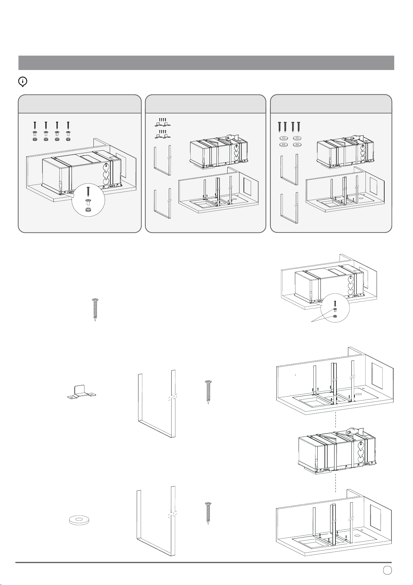
Fastening the System Into Place
INSTALLATION INSTRUCTIONS
ree Methods Are Available for Fastening:
Use the given screws to x the system directly
onto the pre-assembled spacers on the base
• Use the given screws to x the system
directly onto the pre-assembled spacers
on the base.
Use the given screws and brackets to x the
belts into place, which are used to strap the system
Use the given screws and washers to x the
belts into place, which are used to strap the system
Pre-assembled
on the base
x4
•
Use the given screws and brackets to x the
belts into place, which are used to strap the
system.
x8
x4
x2
x4
•
Use the given screws and washers to x the
belts into place, which are used to strap the
system.
Select the method that works best for the installation and proceed.
x4
x2
OR
OR
Strap in system
Strap in system
17
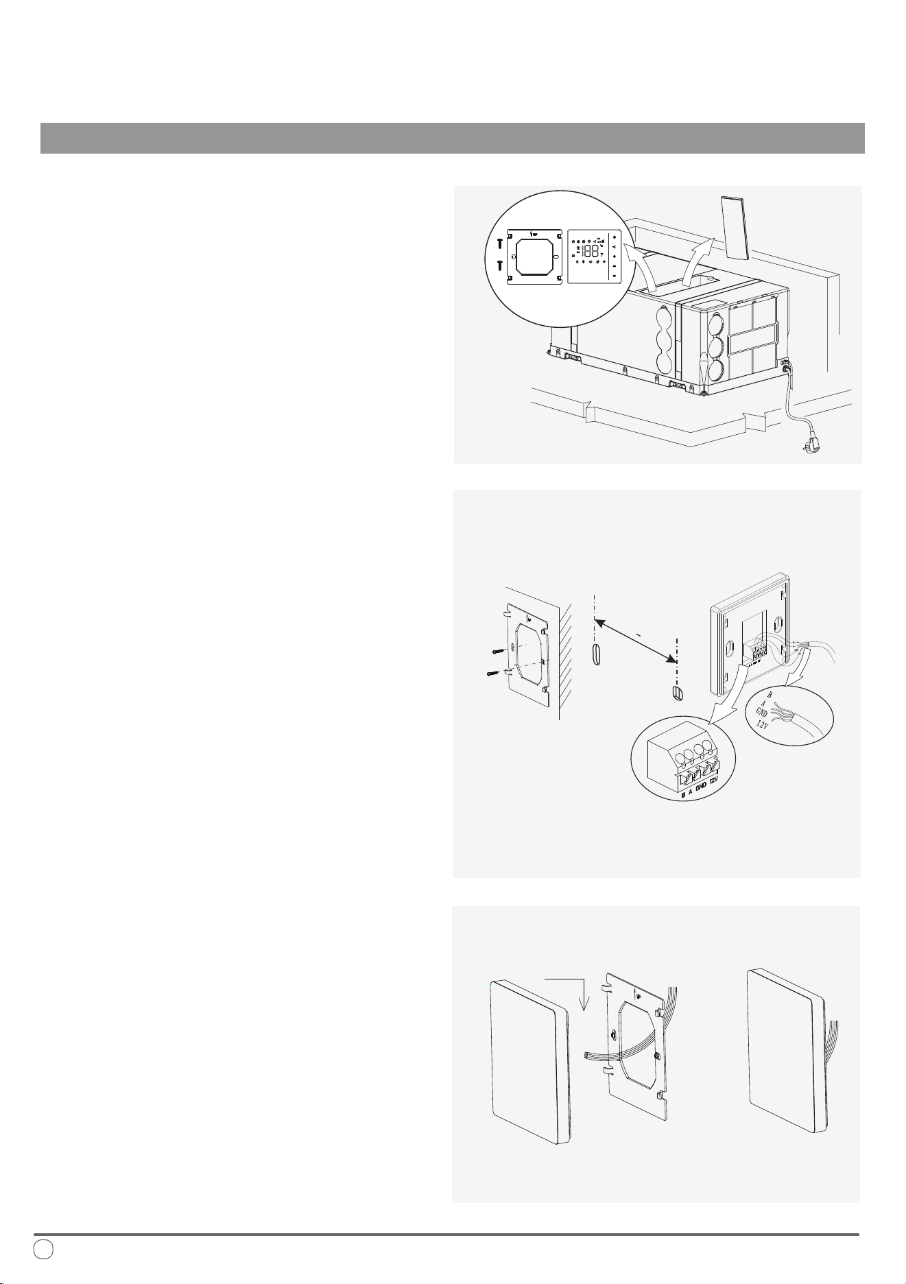
Locate the wall thermostat, handheld
remote controller, batteries, thermostat
support bracket, and extension cable.
ese items are typically found within
the hidden compartment on top of the
system itself during rst installation.
Secure the steel plate to the wall using
self-tapping screws. e distance
between the two holes should be 2”-3/8
inches, and the hole diameter should be
less than 2 inches. Use M4 x 1.5 cm pan
head, cross-point, self-tapping screws.
Once the wiring is properly connected,
position the thermostat against the steel
plate and slide the buckle down to
secure it in place.
e installation is now complete.
INSTALLATION INSTRUCTIONS
Placement of the Wall ermostat
Cable
Outlet Slot
2-3/
8 +1/16
"
"
18
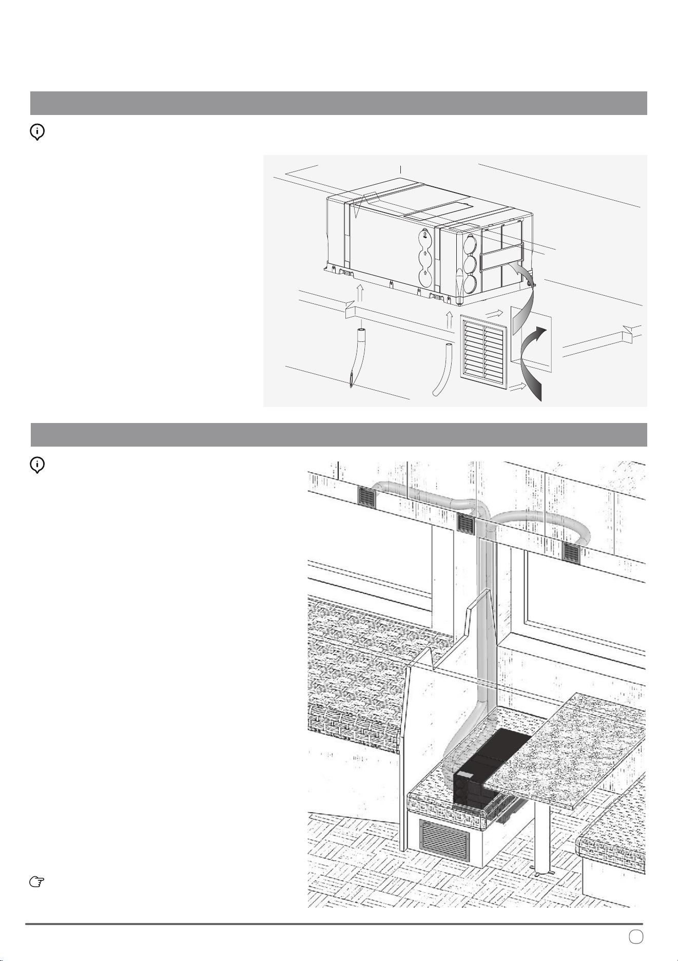
Recirculation Air Compartment Opening
INSTALLATION INSTRUCTIONS
Final Cutout Opening for Recirculation Air:
Ductwork Best Practices:
Air Ducting
Create an additional hole in the compartment
where the system is installed, in order to permit
recirculation of the internal air.
It would be best to locate the cutout near to the
front of the machine. If the opening cannot be
made near the machine, ensure that the air ow is
not obstructed by anything and create an air duct
between the opening and the machine, if necessary.
e cutout should be roughly 50 in
2
in size, and
the hole will be closed with a grille supplied.
Only allow this recirculation air to enter the
compartment from within the passenger section.
If the air entering this opening is from the outside,
the performance of the machine would diminish.
Finally, install the condensation drain tubes
provided with the system onto the bottom ports.
Craft the ducting used to distribute the air using trade
parts which are not included with this system supply.
It is advised to use cardboard pipe for air conditioning,
with an aluminum core and external PVC covering.
e nominal Inner Diameter should be sized up to 2”-3/8,
and the Outer Diameter up to 2”-1/2.
e tapered hole on the air outlet allows the ventilation
ducts to be joined by pressing them together.
Use either the outlet on the coil side, or the side outlet (by
removing the guard and closing the front holes) to connect
the ducts.
e ventilation pipes are connected by pressing them into
the tapered hole on the air outlet. e pipes can be attached
either to the outlet on the coil side or, by removing the
guard and closing the front holes, to the side outlet.
A compatible PIONEER air distribution kit is conveniently sold online under
reference item number IKT-UB3AO-10DHK.
For optimal eciency, it is advised to:
• Route the air ducts as short and at as possible.
• Do not exceed 16 ft in duct length.
• Avoid laying the air ducts near any sources of heat.
Avoid condensation on the ducting by insulating the
pipes with insulation material (sold separately).
19
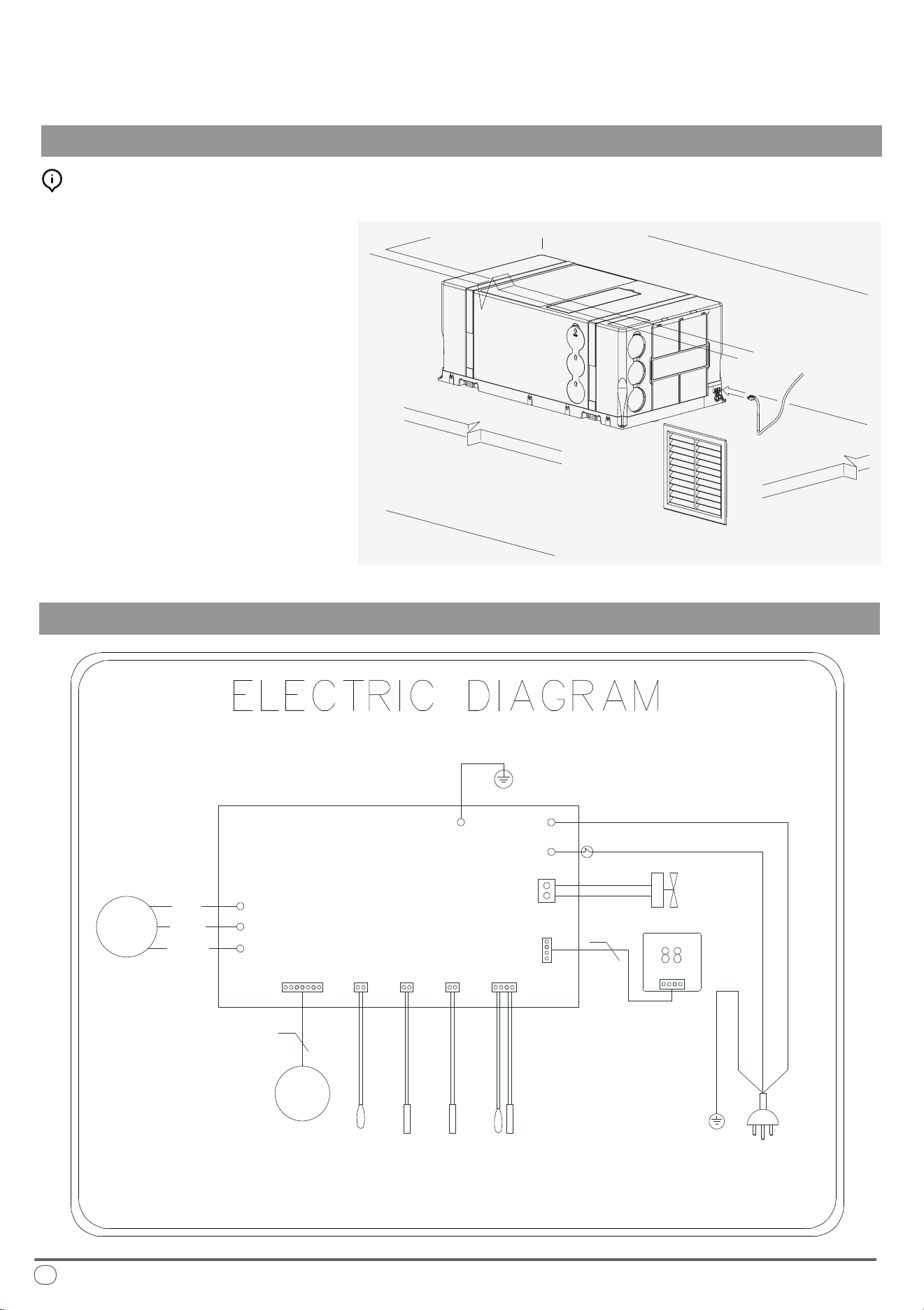
Electrical Hookup
INSTALLATION INSTRUCTIONS
Simplied Wiring Diagram of PYR009AZUDCIPD
Connection and Powering Up of System:
Connect the receiver extension socket to the
system, and power up the machine by inserting
the included power plug into a 115V/60Hz outlet.
Before switching on, ensure that the electrical
supply and the extension used are capable of
withstanding the power input required by the
system (see technical data and/or nameplate).
e installation process is now complete.
For any troubleshooting steps, please see Page 23.
W
V
U
MOTOR
MAIN PCB
POWER PLUG
CN107
BLUE(WHITE)
GR/YE(GR)
BROWN(BLACK)
GR/YE
CN301
AC-L
E1
AC-N
CN351
WIRE CONTROL
4WAY
VALVE
COMP
U
W
V
RED
BLUE
4
WHITE
5
OUTDOOR COIL TEMPERATURE SENSOR
EXHAUST TEMPERATURE SENSOR
OUTDOOR TEMPERATURE SENSOR
ROOM TEMPERATURE SENSOR
CN106
INDOOR COIL TEMPERATURE SENSOR
CN16
CN109 CN105
+12 A B GND
20
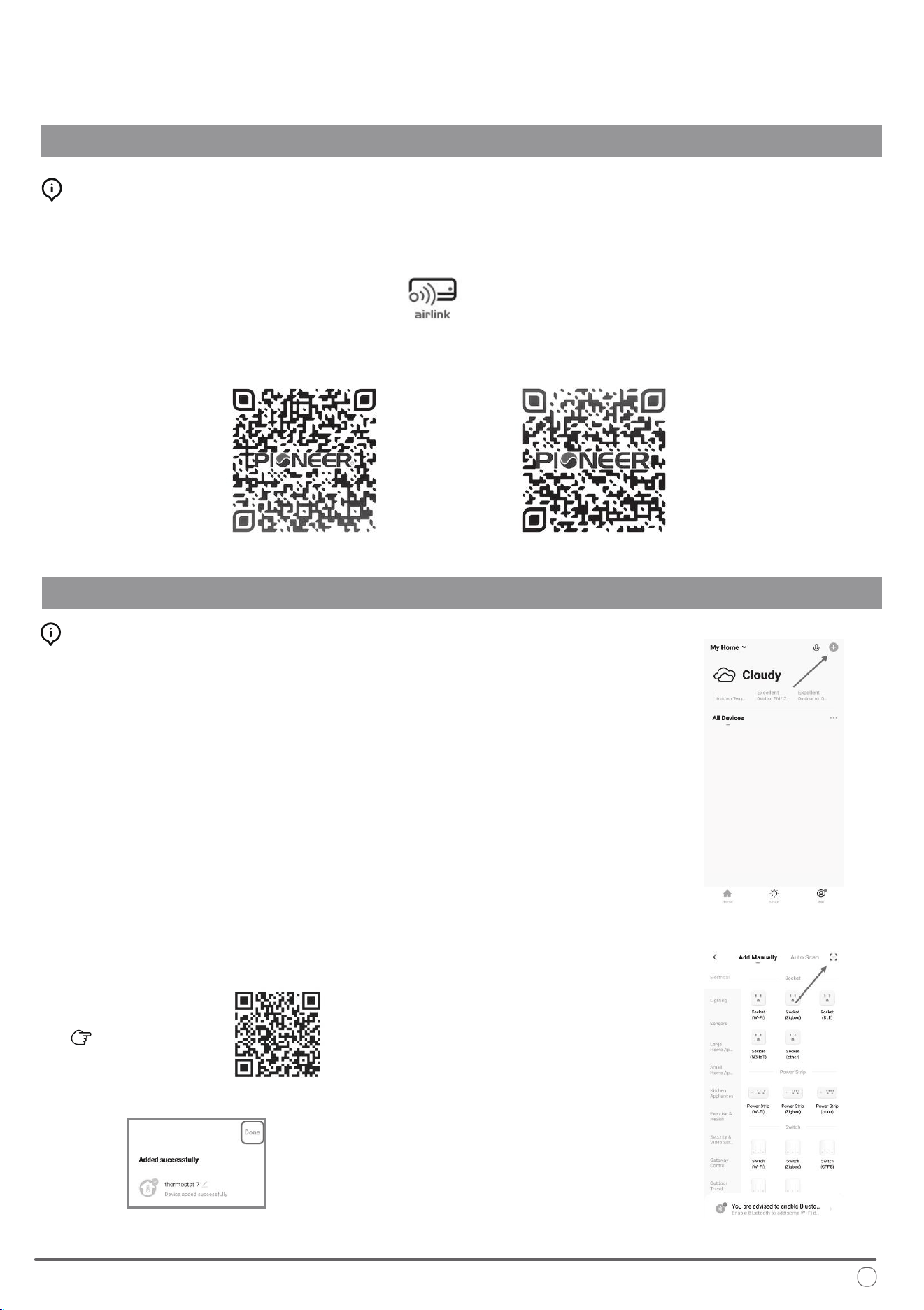
Wireless Internet Connection - Application Download
INSTALLATION INSTRUCTIONS
Wireless Internet Connection - Setup Process
Scan this QR code
Fig.1
Fig.2
Fig.3
Installation of “Pioneer Airlink” smartphone application
Search for “Pioneer Airlink” in the Google Play Store (for Android users) or the App Store (for iOS users).
Note that a 2.4GHz Wi-Fi connection is needed to use the Wi-Fi control feature.
Or, scan the below QR code to download the app from the respective app store.
Download iOS App
Download Android App
i.
ii.
iii. Enter the verication code and select a password. You will then either land on the homepage of
the App, or back to the login interface to log into the app, by using the account you just created.
2. Adding a New Device:
Wireless Control App Setup Process
1. Registration and Log-In:
If you do not already have a “Pioneer Airlink” account, please create and account and log-in
by following the below steps:
Approve the “User Agreement” and “Privacy Policy” when they appear by tapping “I Agree”.
Tap the “Sign Up” button, choose your country, and enter your mobile number/e-mail to register,
tick “I Agree” on “User Agreement and Privacy Policy”, then tap the “Get Verication Code” button.
e phone or e-mail that you’re registering will receive a registration verication code.
i. Conrm that your phone is connected to Wi-Fi (2.4GHz networks only, 5Ghz will not work).
Tap the “+” at the top-right corner of the homepage, to enter the device selection page.
ii. Once you’ve entered this page, locate the [-] button on the top right and scan the below QR code.
e app will conrm that you wish to add the RV system thermostat, select “add”.
78°F
21
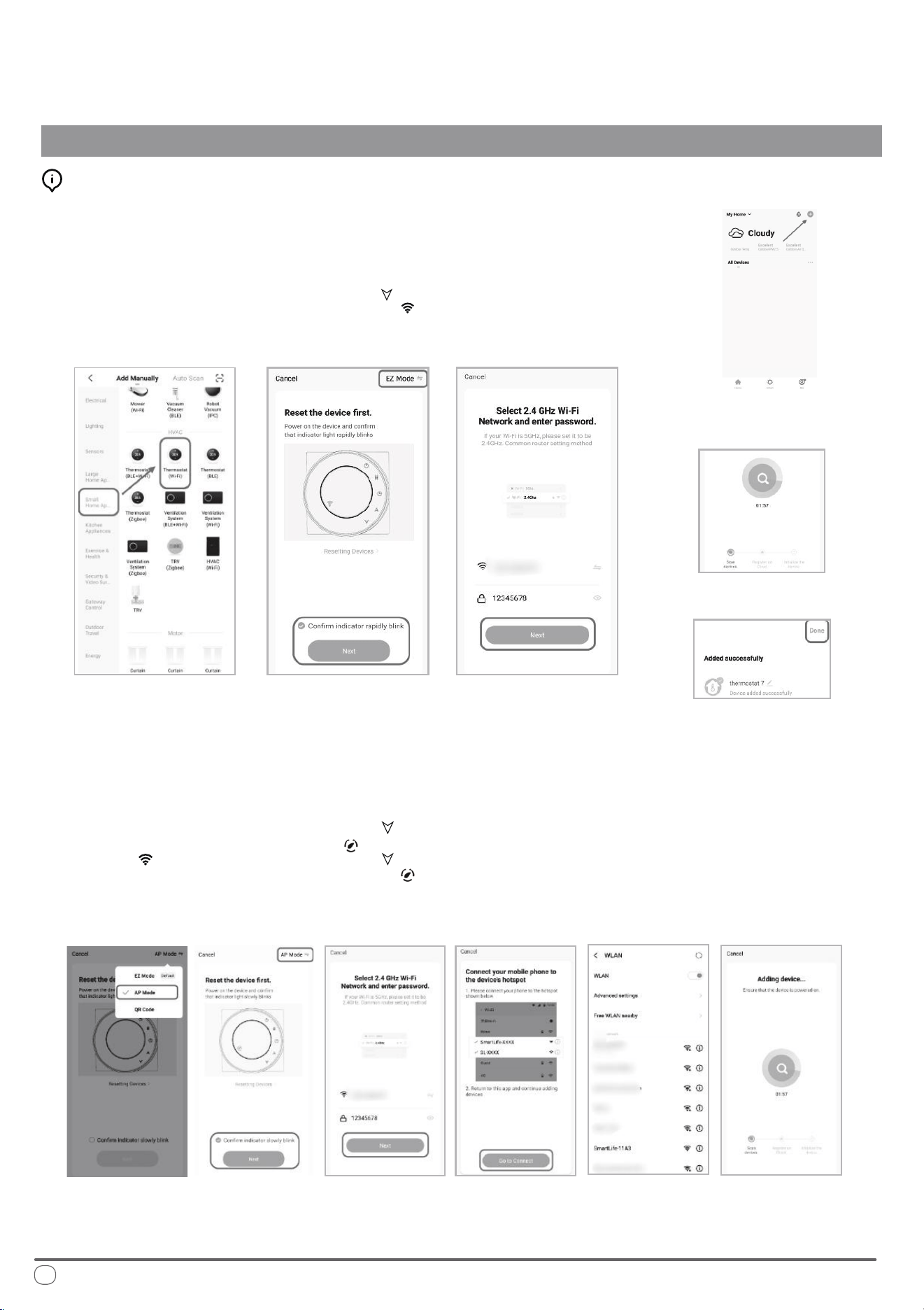
Wireless Internet Connection - Setup Process (Manual Mode)
INSTALLATION INSTRUCTIONS
Conrm that your phone is connected to Wi-Fi (2.4GHz networks only, 5Ghz will not work).
Tap the “+” at the top-right corner of the homepage, to enter the device selection page. (Fig. 1)
i.
ii.
Fig.1
Fig.4
Fig.5 Fig.6
Fig.7
Fig.8
Fig.9 Fig.10 Fig.11 Fig.12 Fig.13 Fig.14
78°F
Network Distribution Mode:
1. EZ Mode
When the thermostat is o, press and hold the “ ” until the
thermostat screen ashes quickly and displays the “ ” icon,
and then operate according to the following gures (Fig. 4-Fig. 8)
Conrm that your phone is connected to Wi-Fi (2.4GHz networks only, 5Ghz will not work).
Tap the “+” at the top-right corner of the homepage, to enter the device selection page. (Fig. 1)
i.
ii.
2. AP Mode
When the thermostat is o, press and hold the “ ” until the
thermostat screen ashes slowly and the “ ” icon is displayed
(if the “ ” icon appears, continue to press the “ ” until the
thermostat screen Flashes slowly and displays the “ ” icon), and
then operate according to the following gure (Fig.9-Fig.14 + Fig. 8)
22
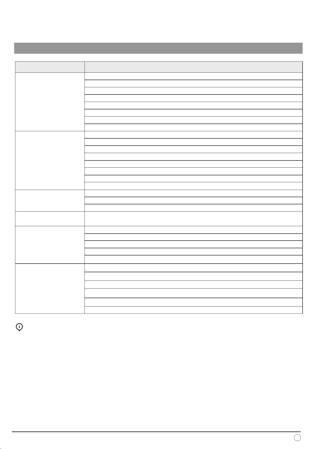
Troubleshooting and Diagnosis
TROUBLESHOOTING, MAINTENANCE, RECYCLING
MALFUNCTION
If the machine
does not start...
If there is water seeping
into the vehicle...
If the appliance
is not cooling...
If the appliance
is not heating...
If the machine
stops working...
POSSIBLE CAUSES
e current temperature is lower than 64°F
e set point temperature has been satised
Defective thermistor or thermal protection
Low refrigerant
e compressor is damaged
e heat exchanger coils are dirty
e MODE button is not in the right position
e external fan is defective
e set point temperature has been satised
e current temperature is higher than 86°F
Defective thermistor or thermal protection
Damaged/Stuck 4-Way Valve
e MODE button is not in the right position
e compressor is damaged
Low refrigerant
e heat exchanger coils are dirty
e internal/interior fan is malfunctioning
e heat exchanger coils are dirty
e air lter is dirty/obstructed
e condensate drain hose is cracked, clogged,
or is not secured onto the exhaust port
e voltage is too low (less than 100V)
ere is insucient power going into the unit
Defective thermal protection
Damaged Compressor
Defective thermistor or thermal protection
e electric condenser is damaged/malfunctioning
e heat exchanger coils are dirty
e air lter is dirty/obstructed
e external fan is defective
e voltage is too low (less than 100V)
e electric condenser is damaged/malfunctioning
Special Supplemental Maintenance:
For optimal eciency, it is recommended to have
your dealer/contractor perform designated cleaning
prior to using, on the heat exchange coils and the
condensation drain holes.
If the airow is insucient,
or no longer circulates
inside the vehicle...
23

Querying the System for Errors
When in startup mode, press and hold the "UP" button for 3 seconds. e system
will beep three times, indicating that the real-time operating frequency of the
compressor is being checked.
To exit the frequency query function and return to the normal display, press and
hold the "UP" button again for 3 seconds. e system will beep twice
simultaneously to conrm the action.
Troubleshooting and Diagnosis
TROUBLESHOOTING, MAINTENANCE, RECYCLING
Fault Code Information
A1 Indoor side EE malfunction
A2 Evaporator fan motor malfunction
A4 Evaporator sensor malfunction
A5 Indoor ambient temperature sensor malfunction
Er Communication failure between main board and thermostat
E5
E6
Four-way valve reversing failure
Low refrigerant fault
A8 Outdoor EE malfunction
B4 The compressor starts abnormally (Lack of phase/reversal)
B5 Compressor out-of-step failure
B6 IPM Module failure
B8 Discharge air temperature sensor malfunction
C2 Condensor temperature sensor malfunction
C3 Outdoor ambient temperature sensor malfunction
C4 Outdoor DC fan motor failure
FL Full water pan protection shutdown
D1 The outdoor unit has shut down for AC current protection
D2 Compressor phase current protection shutdown
D3 Outdoor side AC voltage high/low protection
D4 DC bus voltage high/low protection
D5 IPM high temperature protection shutdown
D6 Discharge air temperature too high cause shutdown protection
D7 Cooling evaporator anti-freezing protection shutdown
D8 Condenser coil overheat shutdown protection in cooling mode
E1 Heating mode evaporator overheat protection shutdown
E2 Protection shutdown against low outdoor ambient temperature at cooling mode
E3 Protection shutdown against high outdoor ambient temperature at heating mode
C5 Drive bus overvoltage protection
C6 Drive bus for undervoltage protection
C7 Drive phase current overcurrent fault
C8 Abnormal phase current sampling
24
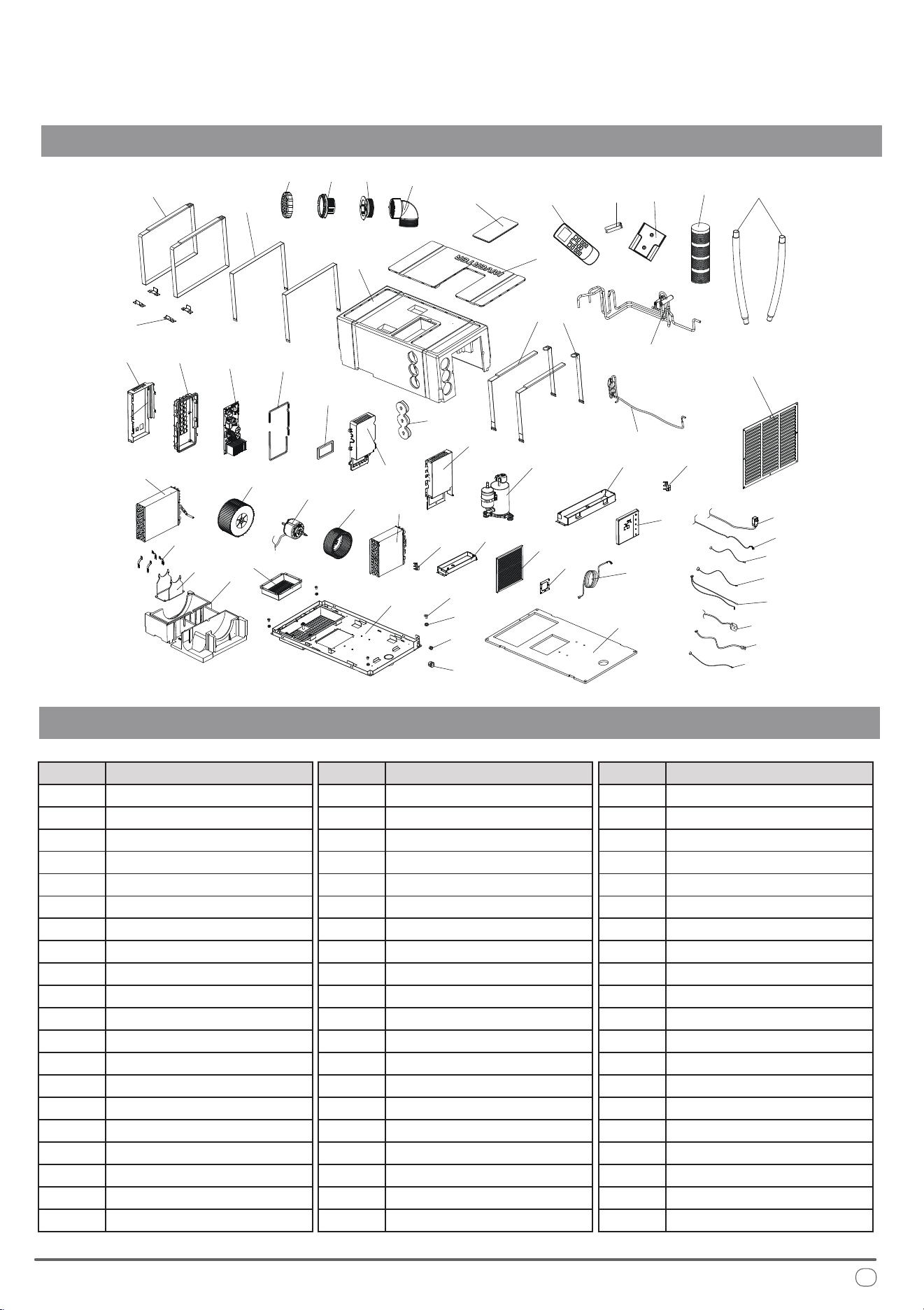
Exploded Parts Diagram of PYR009AZUDCIPD
TROUBLESHOOTING, MAINTENANCE, RECYCLING
Spare Parts Reference List of PYR009AZUDCIPD
1 2
3 4
15
6
9
8
7
6
11
12
13
14
16
17
18
19
20
21
10
22
23
24
25
26
27
28
29
30
31
41
53
54
55
56
57
58
59
60
32
33
34
35
36
37
38
39
40
42
43
44
45
51
50
46
47
48
49
52
Description
1
Ref. No.
GRILLE
2 GRILLE SUPPORT
3 BUSHING
4 90° ELOW
5 REMOTE CONTROL
6 DRAIN PIPE
7 AIR PIPE
8
9
REMOTE SUPPORT
BATTERIES (AAA)
10 RETURN AIR GRILLE
11 BUCKLE
12
13
FASTENING BELT C
14
EPP FASTENING PLATE
15
ACCESSORY BOX EPP
HOUSING COVER EPP
16 HOUSING EPP
17
18
AIR OUTLET PLUG EPP
19
FIXING BELT A
20
FIXING BELT C
CAPILLARY ASSEMBLIES
DescriptionRef. No.
21
22
4-WAY VALVE ASSEMBLIES
23
ELECTRIC BOX BASE PLATE
PCB MOUNTING BOX BASE
24 PCB MAIN BOARD
25 SILICONE SEAL
26 HEATSINK COVER
27 PCB MOUNTING COVER
28
29 COMPRESSOR
30
ELECTRICAL BOX PLATE
DRAIN PAN FOR COND.
31 SENSOR BRACKET
32 CONDENSER
33
34
CONDENSER FAN BLOWER
MOTOR
35
36
EVAPORATOR FAN BLOWER
37
EVAPORATOR
SENSOR BRACKET
38
39
DRAIN PAN FOR EVAP
40
FILTER
WALL CONTROL BRACKET
DescriptionRef. No.
41
42
WALL PAD CONTROLLER
43
WALL PAD WIRE HARNESS
MOTOR RETAINING CLIP
44 MOTOR BRACKET
45 BASE EPP
46 PLASTIC BRACKET
47 RUBBER BRACKET
48
49
FASTENER (PAD HARNESS)
FASTENER (POWER CORD)
50 CHASSIS
51
52
AIR OUTLET FIXING PLATE
CHASSIS FOAM
53 POWER CORD
54 PAD CONNECTION CORD
55 OUTDOOR TEMP. SENSOR
56 OUTDOOR COIL SENSOR
57 INDOOR TEMP SENSORS
58
59 MOTOR WIRING HARNESS
60
4-WAY VALVE COIL
DISCHARGE TEMP. SENSOR
25
European Disposal Guidelines
TROUBLESHOOTING, MAINTENANCE, RECYCLING
is appliance contains refrigerant and other potentially hazardous materials. When disposing of this
appliance, the law requires special collection and treatment. Do not dispose of this product as household
waste or unsorted municipal waste.
When disposing of this appliance, you have the following options:
• Dispose of the appliance at a designated municipal electronic waste collection facility.
• When buying a new appliance, the retailer takes back the old appliance free of charge.
• e manufacturer takes back the old appliance free of charge.
• Sell the appliance to certied scrap metal dealers.
Special Notice
Disposing of this appliance improperly, or in other natural surroundings, endangers your health
and is bad for the environment. Hazardous substances may leak into the ground water and enter
the food chain. Please follow proper disposal protocol.
26

is page intentionally left blank

is page intentionally left blank

is page intentionally left blank

e design and specications of this product are subject to change without prior notice
as development continues. Consult with the sales agency or manufacturer for details.
Refer to the equipment nameplate for all other applicable specications.
is a registered trademark of Parker Davis HVAC International
Parker Davis HVAC International
7290 NW 77th Court, Miami, FL 33166 - USA
Tel : (305) 513-4488
Fax : (305) 513-4499
E-mail : [email protected]
Website : www.pd-hvac.com
Pioneer product line, parts, and supplies are
available online for convenient ordering at:
www.highseer.com
www.pioneerminisplit.com
Scan the below code to visit our support page
where you can nd more installation materials:
Copyright 2025, Parker Davis HVAC International - All rights reserved.