Before using or installing your TURBRO
Split Air Conditioner, please read this manual
carefully and retain it for future reference.
SPLIT AIR
CONDITIONER
Model:
FM9K115 FM9K230
FM12K115 FM12K230
FM18K230 FM24K230
[email protected] www.turbro.com
01
Tips for First-Time Use
1. Allow the unit to sit upright for at least 3-4 hours before powering on. Shipping
carriers may set the unit on its side, which causes the refrigerant to pool in
certain areas. Standing the unit upright for 3-4 hours allows the refrigerant to
move freely within the coils.
2. Some parts with sharp edges may cause injury, so gloves are highly
recommended for unpacking and installing.
3. If you have any diiculties during installation, please contact our Customer
Support Team via support@turbro.com for help.
4. If you have any problems with your product, please send us an email before
submiing a return request, as there might be a simple solution for your issue.
Please read this user manual carefully before installing and operating the
unit.
Caution: Risk of fire
Before using the appliance, read the owner’s manual first.
Before installing the appliance, read the installation manual first.
Before repairing the appliance, read the service manual first.
The images in this manual are for reference and may dier slightly from the
actual items received, please refer to the received items for reference.
Caution, risk of fire
[email protected] www.turbro.com
02
WARNING
1. This air conditioner uses R32 flammable refrigerant. If mishandled this
refrigerant, like other refrigerants, may cause serious bodily harm or property
damage.
2. Do not use means to accelerate the defrosting process or to clean the unit
other than those recommended in this user manual. Should repair be
necessary, contact the TURBRO Customer Service Team.
3. Any repairs carried out by unqualified personnel may be dangerous.
4. Do not pierce or burn refrigerant lines or any other components.
5. Read the user manual in its entirety before beginning installation or
operation.
[email protected] www.turbro.com
SAFETY INFORMATION
PARTS DESCRIPTION
INSTALLATION
Indoor Unit Installation
Outdoor Unit Installation
Inspection before Use
OPERATION
Operating from the App
Operating from the Remote Control
CLEANING
Warning
Cleaning the Outer Case
Cleaning the Filter
Maintenance Checklists
MALFUNCTION CODES
TROUBLESHOOTING
WARRANTY & CUSTOMER SUPPORT
Warranty Information
Customer Support
······························································04
································································06
············································································09
································································10
······························································17
··································································27
·················································································28
································································28
··············································32
···················································································43
······················································································43
······························································43
·······································································44
·······························································45
······························································45
··································································46
·······································49
··································································49
······································································50
CONTENTS
03
Please read all instructions before use and save this user manual for future
reference. A digital version can be obtained from Customer Support.
Your safety and the safety of others are very important to us. We have provided
many important safety messages throughout this manual and on the appliance.
Always read and follow all posted safety messages.
Please follow some basic safety precautions to reduce the risk of fire, electric
shock, injury, or death to persons using or near this appliance. These precautions
include, but are not limited to, the following:
Installation and Setup
● This appliance is not intended for use by any persons (including children) with
reduced or restricted physical, mental, or sensory capabilities, or lack of
experience and knowledge, unless under the direct supervision of a person
responsible for their safety.
● Please keep plastic bags and sheets out of the reach of children as they might
be mistakenly used for play. Packaging materials can become airtight chambers
and may pose a risk of suocation if not disposed of properly.
● Before use, check whether the product is visibly damaged, malfunctioning,
disassembled, or has missing or broken parts. If any of those are true, consult
a professional or TURBRO customer service team to ensure the unit can
operate normally. Use only authorized TURBRO factory OEM parts.
● Keep the product away from fire. Do not store or use flammable gases or
materials near the appliance.
● In the event of a gas leak (propane gas, LP gas, etc.) do not operate this or any
other appliance. Open a window or door to ventilate the area immediately.
Electrical Safety Warning
● Protect the indoor unit with a fuse of suitable capacity for the maximum input
current or with another overload protection device.
● This product should be connected to a properly rated, protected, and sized
power supply to avoid electrical overload.
[email protected] www.turbro.com
SAFETY INFORMATION
04
● Your air conditioner must be used in a properly grounded wall receptacle. If
the wall receptacle you intend to use is not adequately grounded or not
protected by a time-delay fuse or circuit breaker, have a qualified electrician
install the proper wall power receptacle before using this appliance.
● During the installation or moving of the appliance, be careful not to pinch,
crush, or damage the wires. Always disconnect the unit from the power
supply before cleaning or maintenance operations.
● The baeries in the remote controller must be recycled or disposed of properly.
For disposal of scrap baeries, please discard the baeries as sorted municipal
waste at the accessible collection point.
● Do not obstruct the air inlet or outlet of the indoor or outdoor unit. Obstructions
may cause a reduction in the overall eiciency of the air conditioner with
possible consequent failures or damages.
● Do not climb onto or place any objects on the outdoor unit.
FCC Caution
This device complies with part 15 of the FCC Rules. Operation is subject to the
following two conditions:
(1) This device may not cause harmful interference, and (2) this device must
accept any interference received, including interference that may cause
undesired operation.
Any Changes or modifications not expressly approved by the party responsible
for compliance could void the user’s authority to operate the equipment.
Note: This equipment has been tested and found to comply with the limits for a
Class B digital device, pursuant to part 15 of the FCC Rules. These limits are
designed to provide reasonable protection against harmful interference in a
residential installation. This equipment generates uses and can radiate radio
frequency energy and, if not installed and used in accordance with the
instructions, may cause harmful interference to radio communications. However,
there is no guarantee that interference will not occur in a particular installation.
If this equipment does cause harmful interference to radio or television reception,
which can be determined by turning the equipment o and on, the user is
encouraged to try to correct the interference by one or more of the following
measures:
● Reorient or relocate the receiving antenna.
[email protected] www.turbro.com
05
● Increase the separation between the equipment and receiver.
● Connect the equipment to an outlet on a circuit dierent from that to which
the receiver is connected.
● Consult the dealer or an experienced radio/TV technician for help.
● The distance between the user and the device should be no less than 20cm.
NOTE: If the remote control is not working, press the Manual Buon to operate
the air conditioner.
[email protected] www.turbro.com
06
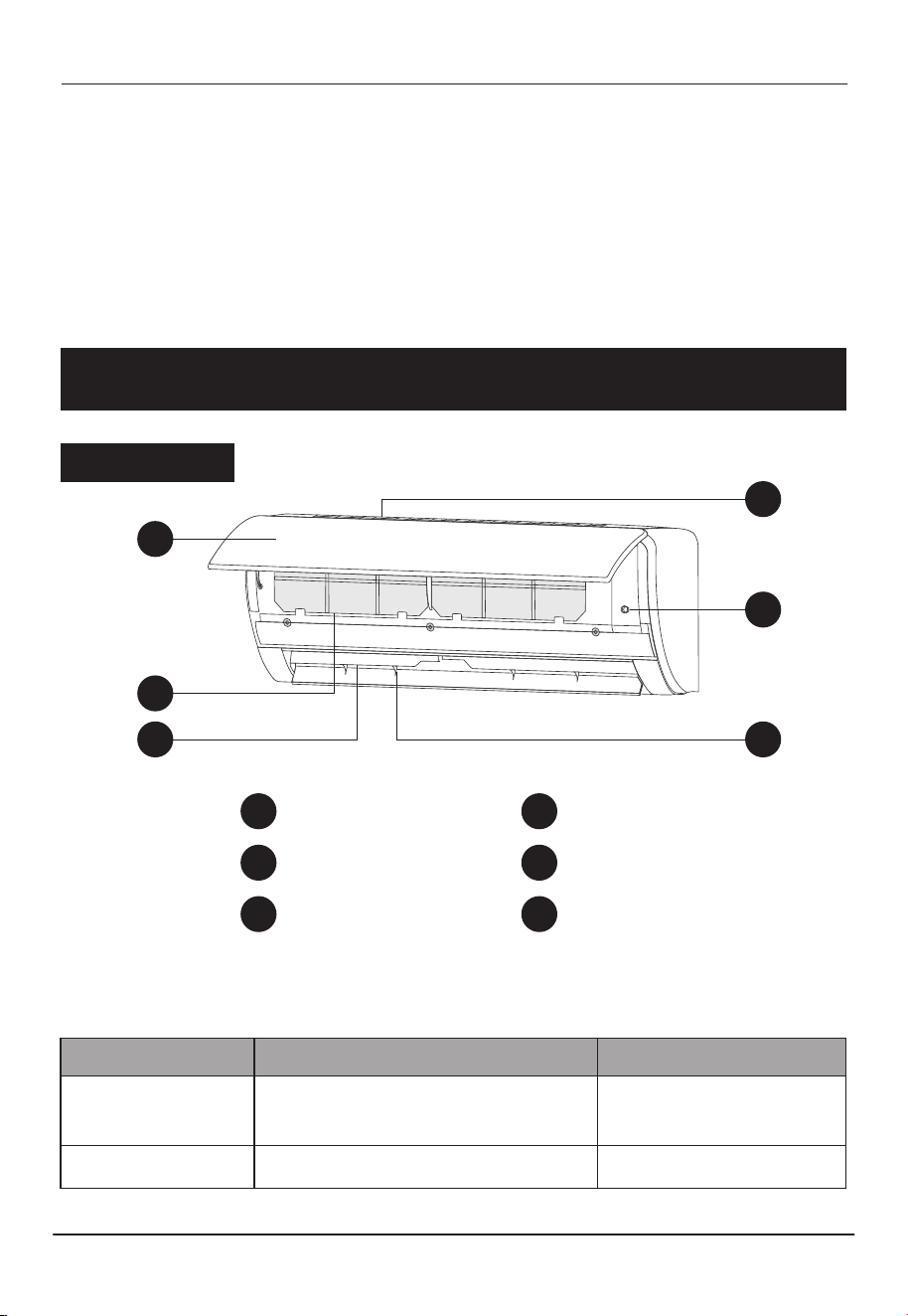
PARTS DESCRIPTION
Indoor Unit
2
1
3
5
1
Front Panel
2
Filter
3
Air Outlet
4
Air Inlet
5
Manual Buon
6
Deflector
6
4
Current status Operation Respond
The unit is OFF.
The unit is ON.
Press the manual buon once
Press the manual buon once
It will turn on and
enters Auto mode.
It will stop running.
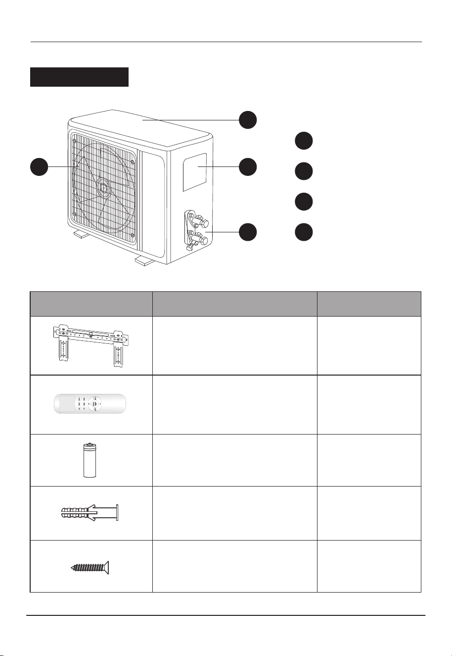
1
Air Inlet
2
Air Outlet
3
Wiring Box
4
Pipe Connections
[email protected] www.turbro.com
07
Outdoor Unit
1
32
4
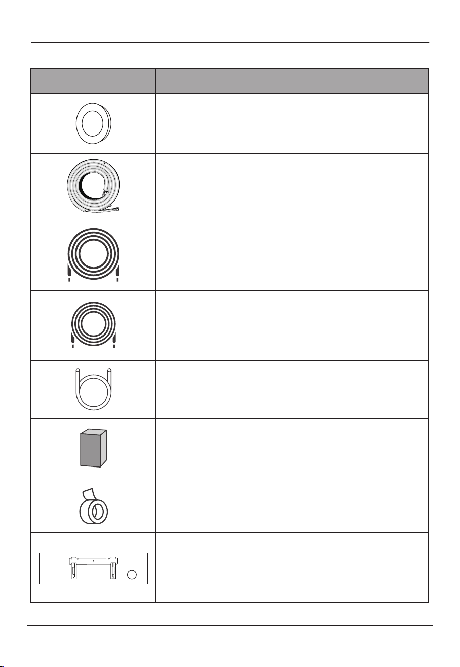
Parts Parts Name Quantity
Mounting plate 1
Remote control 1
AAA baery 2
Wall anchors 1 set
Screws 1 set
[email protected] www.turbro.com
08
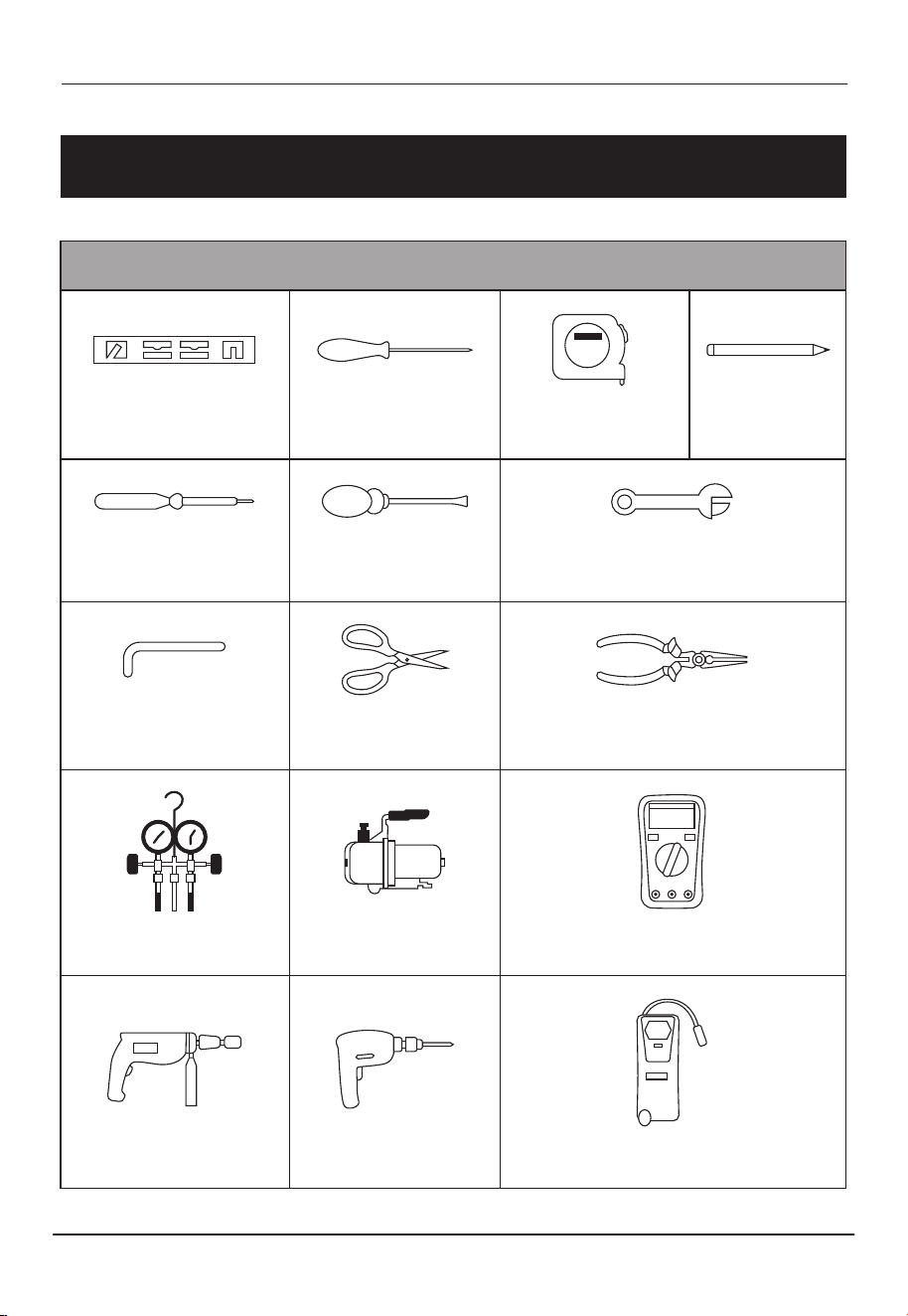
Parts Parts Name Quantity
Wall sleeve 1
Refrigerant pipe (13.1ft/4m) 2
Signal cable (14.8ft/4.5m) 1
Power cable (8.2ft/2.5m) 1
Drain hose (6.6ft/2m) 1
Sealing gum 1
Insulating tape 1
Guide plate 1
[email protected] www.turbro.com
09
Additional Tools Required for Installation (Not included)
Bubble Level
Drill with Hole Saw
Scissors
Torque Wrench
Manifold Gauge
Electronic Leakage Detector
Vacuum Pump
Needle Nose Pliers
Open-end Wrench
Hex Key Set
Voltage Tester
Universal Multimeter
Electric Drill
Pencil Measuring tape Screwdriver
INSTALLATION
Before installing the indoor unit, you need to check the label on the product
box and make sure that the model number of the indoor unit matches the model
number of the outdoor unit. If the model numbers do not match, please contact
customer support.
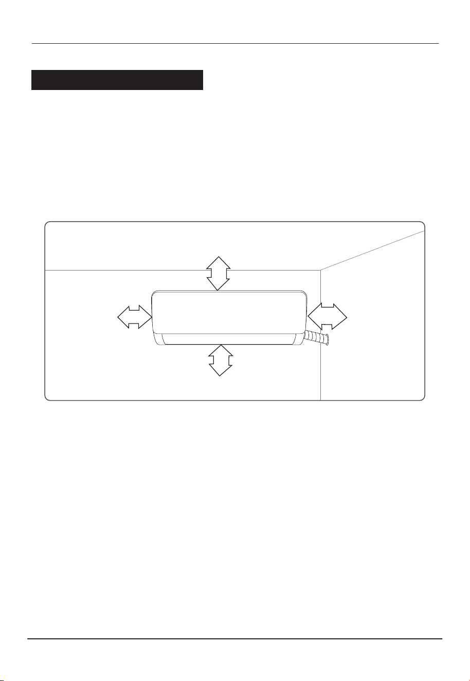
Step 1: Select the Installation Location
Make sure the installation complies with the following diagram.
Check the location meets the following requirements:
● Air inlet and outlet must be clear of obstructions, ensuring proper airflow
throughout the room, and shall keep away from heat sources, and flammable
or explosive conditions.
● Condensation can be easily and safely drained.
● All connections can be easily made to the outdoor unit.
● The mounting wall is strong enough to withstand four times the full weight
and vibration of the unit.
● The filter can be easily accessed for cleaning.
● Leave enough free space to allow access for routine maintenance.
● Do not install it in a laundry room or by a swimming pool due to the corrosive
environment.
[email protected] www.turbro.com
10
Indoor Unit Installation
Cleaning Clearance
Floor Clearance
Wall Clearance
At lease
8 inches/20 cm
At lease
8 inches/20 cm
At lease 6 inches/15 cm
At lease 90 inches/230 cm
Wall Clearance
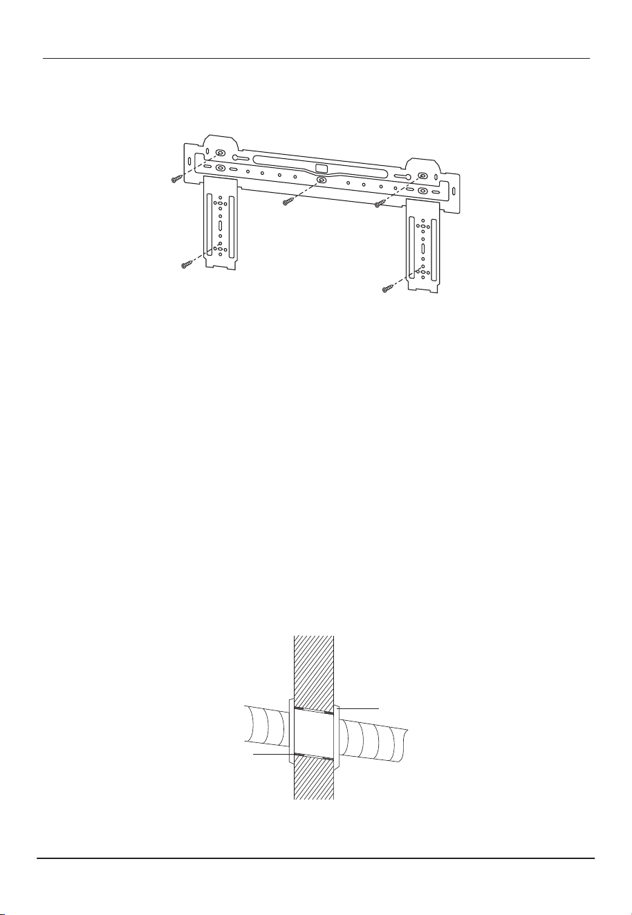
Step 2: Install Mounting Plate
● Remove the mounting plate from the back of the indoor unit.
● Ensure you can meet the minimum installation dimension requirements as
shown in step 1. According to the size of the mounting plate, determine the
position and stick the mounting plate close to the wall.
● Adjust the mounting plate to a horizontal state with a bubble level, then mark
out the screw hole positions on the wall.
● Set the mounting plate down and drill holes in the marked positions.
● If the marked positions do not go into a wall stud, you will need to use wall
anchors. Insert the included wall anchors into the holes, then hang the
mounting plate and fix it with included screws.
Note: Make sure the mounting plate is secured and flat against the wall after
installation.
Step 3: Drill Wall Hole
[email protected] www.turbro.com
11
Wall sleeve
Sealing gum
[email protected] www.turbro.com
12
● Determine the location of the wall hole based on the position of the mounting
plate.
● The hole should have a 60mm~80mm diameter and slant outward by 5°-10°
to facilitate drainage to the outdoors.
● Place the wall sleeve in the hole to protect the connection parts.
Caution: When drilling the wall hole, make sure to avoid wires, plumbing, and
other sensitive components already in your home.
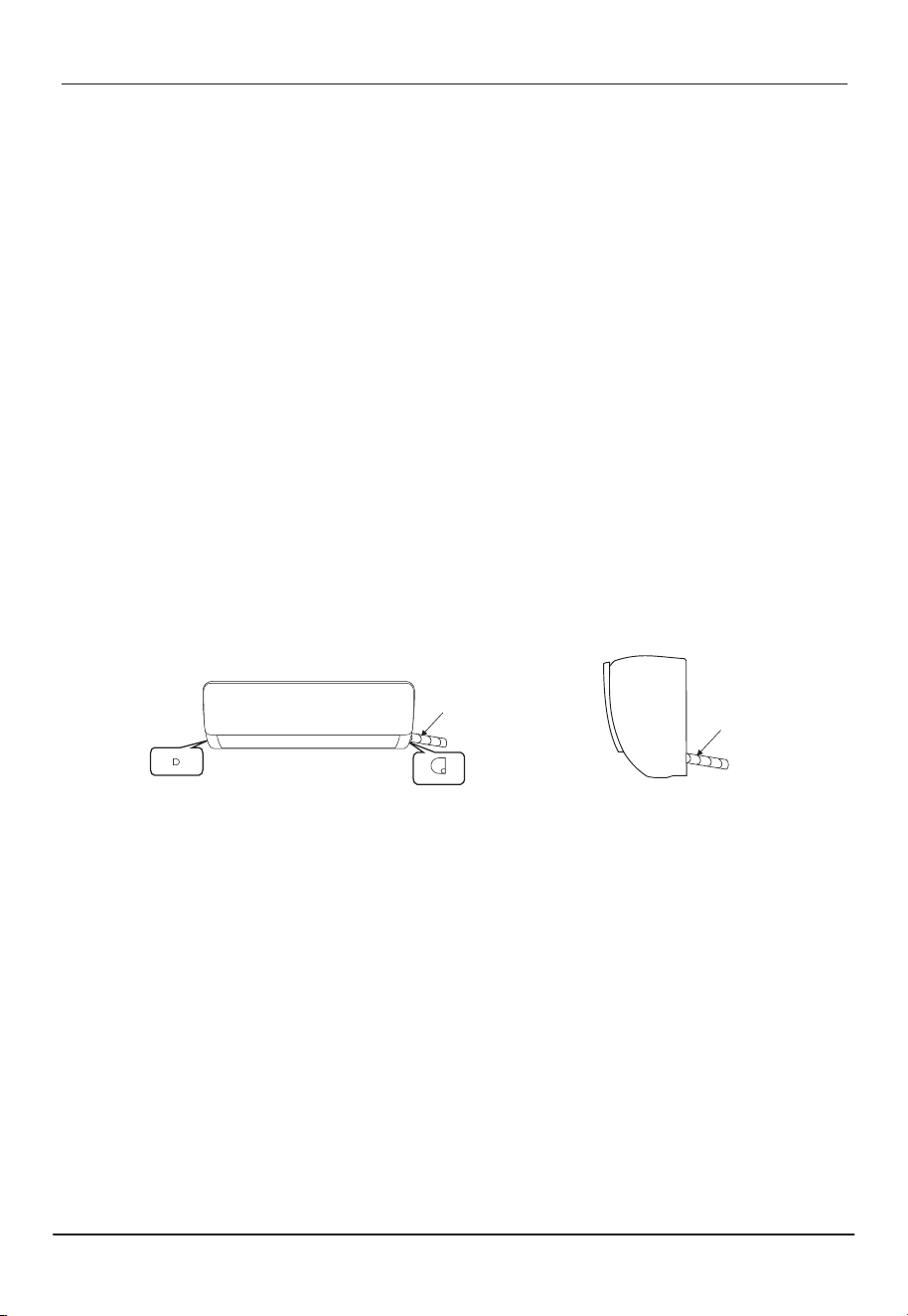
Step 4: Connecting Refrigerant Pipe
● According to the wall hole position, select the appropriate piping mode. The
piping may be routed side from the left or the right side of the indoor
unit (Fig 1), or out from the back of the indoor unit (Fig 2) as shown in the
figures below:
● In Fig 1 piping mode, a notch should be made by using scissors to cut the
plastic sheet covering the piping outlet on the corresponding side of the
indoor unit.
Note: When cuing the plastic sheet for the outlet, the cut should be trimmed
to smooth.
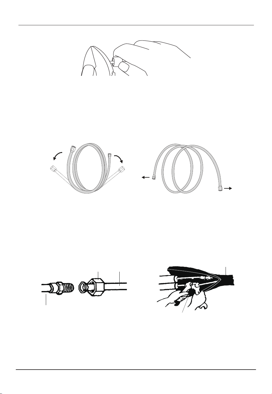
● There should be a small amount of gas in the pipe used for testing before it
leaves the factory. Press the tip of the pipe and you will hear the sound of air
leaking to indicate the pipe sustained no leakage during transportation. If
there is no sound, the pipe may be broken. Please check for leaks or contact
the customer support team.
Fig 1
Connecting Pipe
Drain Hose
and Cables
Connecting Pipe
Drain Hose
and Cables
Hole material
preparation
Outlet material
preparation
Fig 2
[email protected] www.turbro.com
13
● Remove the plastic cover of the refrigerant pipes using two wrenches or pliers.
● Remove the protective cover from the end of the piping connectors.
● Check whether there is any debris on the port of the refrigerant pipe and
ensure the port is clean.
● Bend the refrigerant pipes with the port facing up as shown in the figure below.
● After aligning the refrigerant pipes, rotate the nut of the refrigerant pipe and
tighten it as tightly as possible by hand. Please pay aention that over
-tightening may damage connections and cause leaks.
● Use a proper torque wrench to tighten it according to the Torque Table below.
● Wrap the joint with the insulation pipe.
NOYES
Insulation pipe
Refrigerant pipe
Torque wrench
Refrigerant pipe
Nut
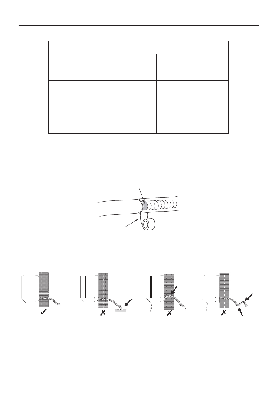
Step 5: Connect Drainage Hose
● Connect the drainage hose to the water outlet and ensure the joint is fully
sealed. Wrap the joint firmly with insulation tape to avoid any leaks.
Note: Make sure there are no twists or dents in the pipe. The pipes should be
oriented downward to avoid blockage.
[email protected] www.turbro.com
14
Newton meter
15-25
35-40
45-60
73-78
75-80
Inch (mm)
1/4 (6.35)
3/8 (9.52)
1/2 (12.70)
5/8 (15.88)
3/4(19.05)
Pound-force foot
11.1-18.4
25.8-29.5
33.2-44.2
53.9-57.5
55.4-59.0
Tighten Torque to: Pipe Size
Tape
Joint
Pitch downwards
Do not put drain hose
end into the water
Do not rise
Do not make a trap
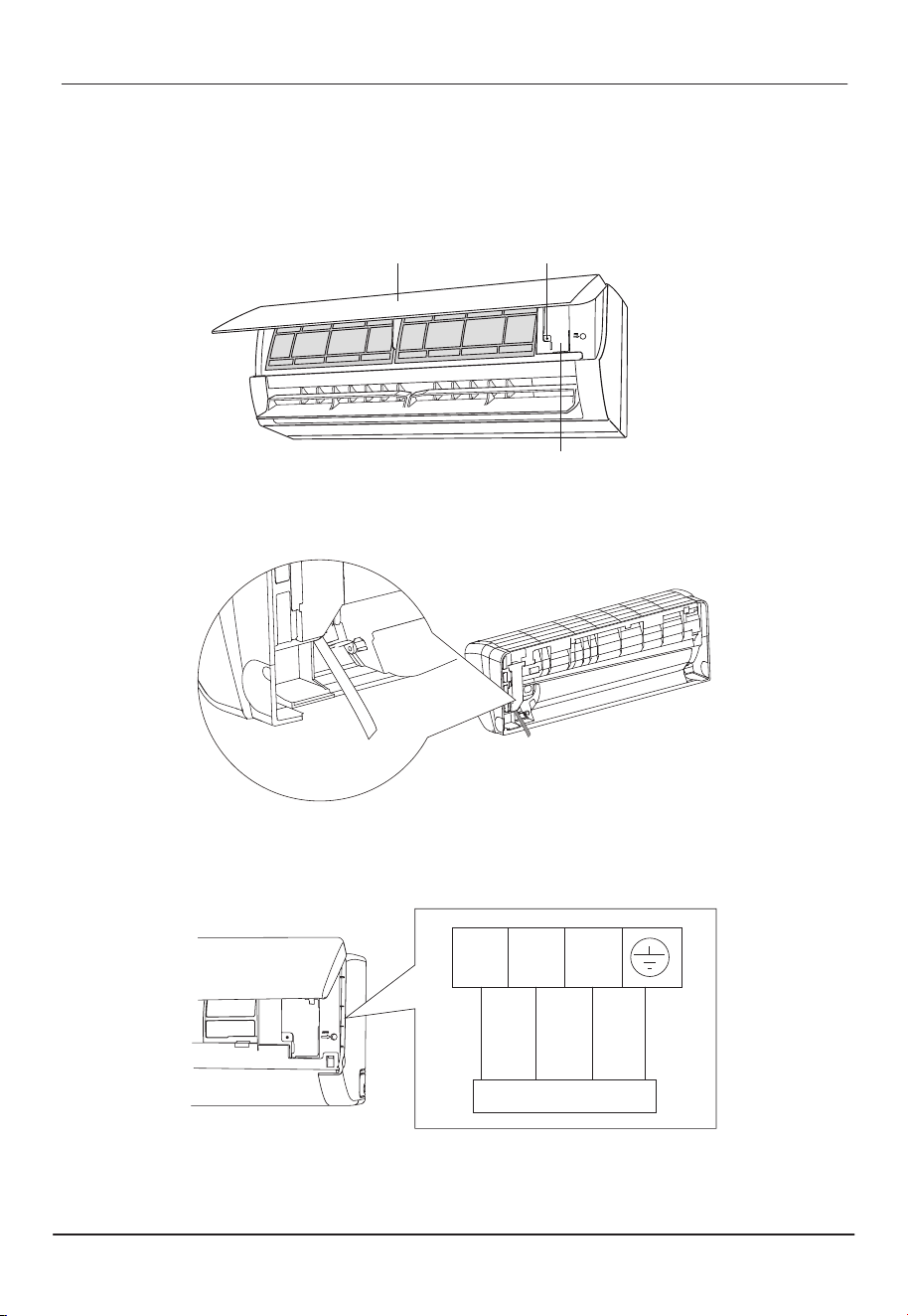
Step 6: Connect Signal Cable
● Open the front panel of the indoor unit. Use a screwdriver to open the electric
control box cover and reveal the terminal block.
● Insert the signal cable into the cable-cross hole at the back of the indoor unit
and then pull it out from the front side.
● Connect the cables to the corresponding terminals according to the wiring
diagram on the inside of the front panel or the picture below. Make sure that
they are connected securely.
● Screw the cable clamp to fasten the cables and reinstall the electric control
box cover and front panel.
[email protected] www.turbro.com
15
Screw
Electric control box
Panel
L1
BK
To Outdoor Unit
WH RD Y/G
L2 S
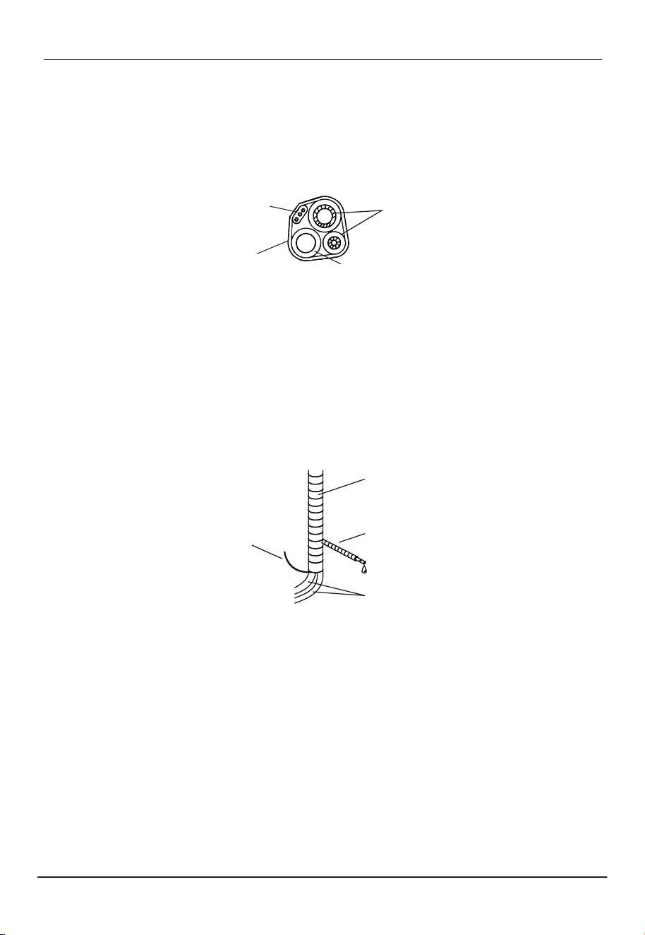
Step 7: Wrap Piping and Cable
● Arrange the pipes, cables, and drainage hose as shown in the figure below.
● Use insulation tape to wrap them tightly together as a bundle.
Step 8: Mount Indoor Unit
● Slowly pass the wrapped bundle through the wall hole.
● Hang the indoor unit on the mounting plate, and move the unit from left to
right to ensure that the hooks are properly positioned in the mounting plate.
Push toward the lower left side and the upper right side of the unit toward the
mounting plate, until the hook is embedded in the slot and makes a "click"
sound.
Note:
● Make sure the drainage hose is at the boom and avoid crossing and bending
of parts.
● Reserve a few inches of the drainage hose. When wrapping to a certain
length, separate the drainage hose. Continue wrapping together and leave a
few inches of the signal cable and refrigerant pipes to wrap separately for
outdoor unit connection. See the figure below.
[email protected] www.turbro.com
16
Signal Cable
Insulat ion tape
Drainage hose
Refrigerant piping
Insulat ion tape
Drainage hose
Refrigerant piping
Signal Cable
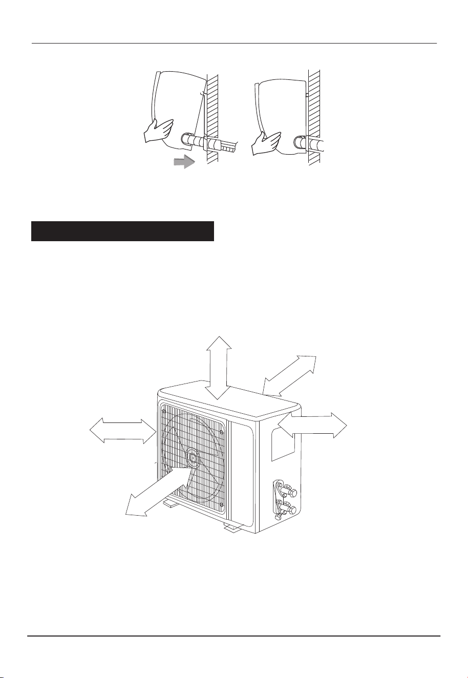
Step 1: Select Installation Location
Select a site that allows for the following as shown in the image below:
Outdoor Unit Installation
Note: The drain hose should slant downwards for drainage. Do not bend or twist.
[email protected] www.turbro.com
17
Air Intake Clearance
Side Clearance
Pipe Connection
Clearance
Air Exhaust Clearance
Interior Clearance
At least 12 inches/30 cm
At least 79 inches/200 cm
At least 20 inches/50 cm
At least 4 inches/10 cm
At least 20 inches/50 cm
● Allow enough space for air to circulate as shown in the figure above. Install the
outdoor unit in a safe and solid place.
● Do not install the outdoor unit near sources of heat, steam, or flammable gas.
● Do not install the unit in windy or dusty places.
● Do not install the unit where people often pass. Select a place where the air
discharge and operating sound will not disturb yourself or neighbors.
● Do not install the unit where it will be exposed to direct sunlight. If that is not
an option, you must use protection for the outdoor unit that will not interfere
with the airflow.
● If the outdoor unit is subject to vibration, place rubber feet onto the feet of
the unit.
● Ensure the secure installation regardless of what type of wall on which it is
installed, to prevent potential dropping that could hurt people.
Step 2: Fix Outdoor Unit
● Mark the installation position for expansion bolts. Drill holes and for the M8
bolts.
● Place the outdoor unit base on the pre-drilled holes.
● Use a wrench to fix the outdoor unit firmly with bolts.
Note: The outdoor unit can also be fixed on a wall-mounted bracket. Install the
bracket according to the included instructions and then fasten the
outdoor unit on it. The wall-mounting bracket must be able to support at
least 4 times the weight of the outdoor unit for safety.
[email protected] www.turbro.com
18
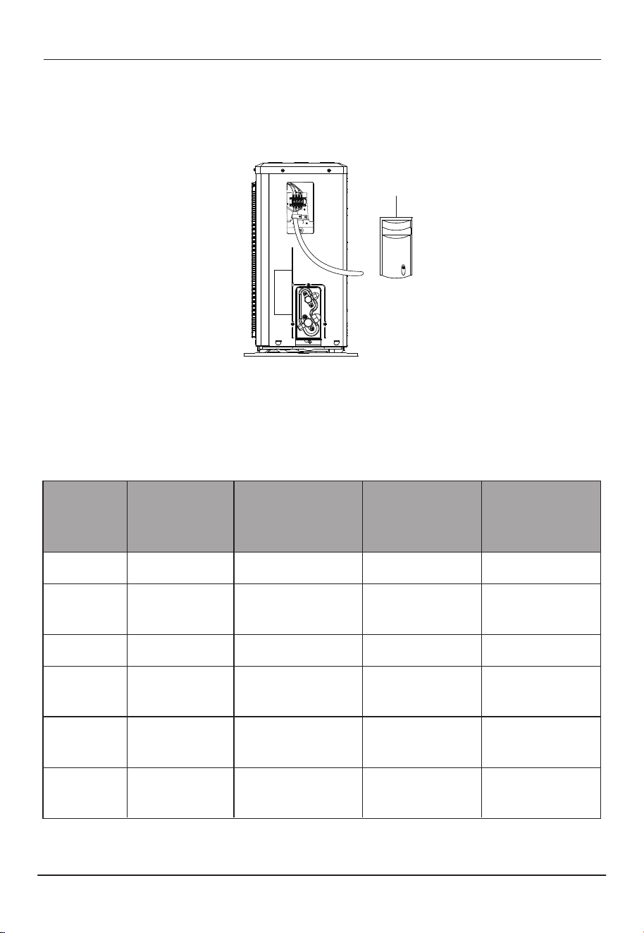
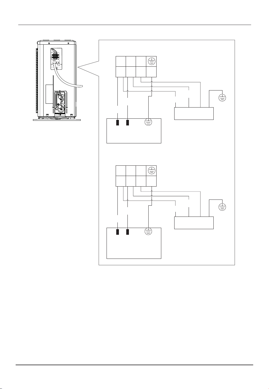
Step 3: Connect Cables
● Loosen the screws and remove the electric wiring cover from the unit.
● Remove the protective cover on the cable. According to the wiring diagram
pasted inside the wiring cover or the picture below, connect the signal and
power cables to the corresponding terminals. Ensure all connections are firm
and secure.
[email protected] www.turbro.com
19
Cover
AWG 16+
AWG 18+
AWG 16+
AWG 18+
AWG 18+
AWG 14+
1.5
1.0
1.5
1.0
1.0
1.5
14
8
14
8
10
15
FM9K115
FM9K230
FM12K115
FM12K230
FM18K230
FM24K230
115V 30-Amp
230V 20-Amp
Double Pole
115V 30-Amp
230V 20-Amp
Double Pole
230V 20-Amp
Double Pole
230V 30-Amp
Double Pole
Min. Circuit
Ampacity (A)
Recommended
Wire Gauge
Recommended
Breaker Size
Model
Minimum Wire
Cross-sectional
Area (mm )
2
● Reinstall the cable clamp and wiring cover.
Note: Make sure that the wires are well-connected. If you have any problems,
consult a professional or TURBRO customer service team.
Make sure both ends of black wires connect to L1, white wires connect to
L2, and red wires connect to S.
[email protected] www.turbro.com
20
L1 L2
WHITE
YELLOW/
GREEN
YELLOW/
GREEN
BLACK
BLACK
WHITE
RED(Singal)
S
LIVE NEUTRAL
Indoor Unit
POWER SUPPLY
(115V Only)
L1 L2
WHITE
YELLOW/
GREEN
YELLOW/
GREEN
BLACK
BLACK
WHITE
RED(Singal)
S
LIVE1 LIVE2
Indoor Unit
Double pole breaker
230V
POWER SUPPLY
9K115V, 12K115V
9K230V, 12K230V, 18K230V, 24K230V
Newton meter
15-25
35-40
45-60
73-78
75-80
Inch (mm)
1/4 (6.35)
3/8 (9.52)
1/2 (12.70)
5/8 (15.88)
3/4(19.05)
Pound-force foot
11.1-18.4
25.8-29.5
33.2-44.2
53.9-57.5
55.4-59.0
Tighten Torque to: Pipe Size
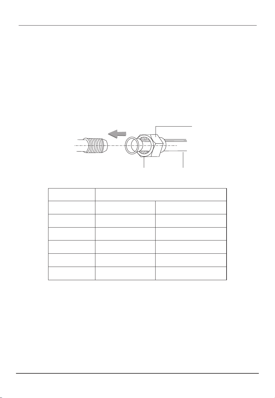
Step 4: Connect the Refrigerant Pipe
● Unscrew the valve cover. Remove the protective caps from the end of the
valves.
● After aligning the refrigerant pipes, rotate the flare nut of the refrigerant pipe
and tighten the nut as tightly as possible by hand.
● Use a spanner to hold the body of the valve and use a torque wrench to tighten
the flare nut according to the torque table below. Please check the flare nut
for the refrigerant pipe size.
Note On Pipe Length
The length of the refrigerant pipe will aect the performance and energy
eiciency of the unit. The refrigerant pipe included is 13.12ft (4 meters) long.
If necessary, you can change the length of the refrigerant pipe. remember to
add or reduce the amount of refrigerant depending on the change in pipe length.
Consult a professional or contact customer support for assistance.
[email protected] www.turbro.com
21
Pipe size
(eg. Φ6.35)
Flare nut
Refrigerant pipe
0.17
0.17
0.26
0.26
9K115, 9K230
12K115, 12K230
18K230
24K230
0.21
0.21
0.43
0.43
Refrigerant Additional
Charge(oz/ft)
Refrigerant Decreasing
Charge(oz/ft)
Model
[email protected] www.turbro.com
22
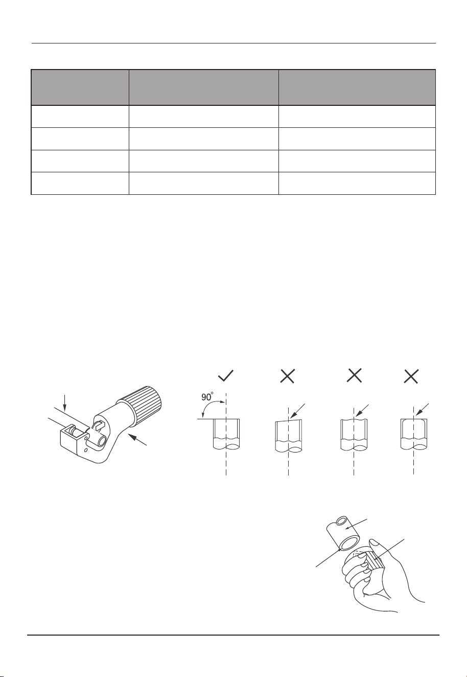
Refrigerant Piping Connection Instructions
Improper pipe shortening or expansion might cause refrigerant leakage. Please
take extra care to cut and flare them properly to ensure the eicient operation
and minimize the need for future maintenance.
▷ Cut pipes
● Measure the distance between the indoor and outdoor units.
● Using a pipe cuer, cut the pipe a lile longer than the measured distance.
● Make sure that the pipe is cut at a perfect 90° angle.
▷ Remove burrs
Burrs can aect the air-tight seal of the refrigerant
piping connection. They must be completely removed.
● Hold the pipe at a downward angle to prevent burrs
from falling into the pipe.
● Using a reamer or deburring tool, remove
all burrs from the cut section of the pipe.
Pipe cuer
Refrigerant pipe
Leaning
Uneven
Burr
Shaper
Downwards
Pipe
[email protected] www.turbro.com
23
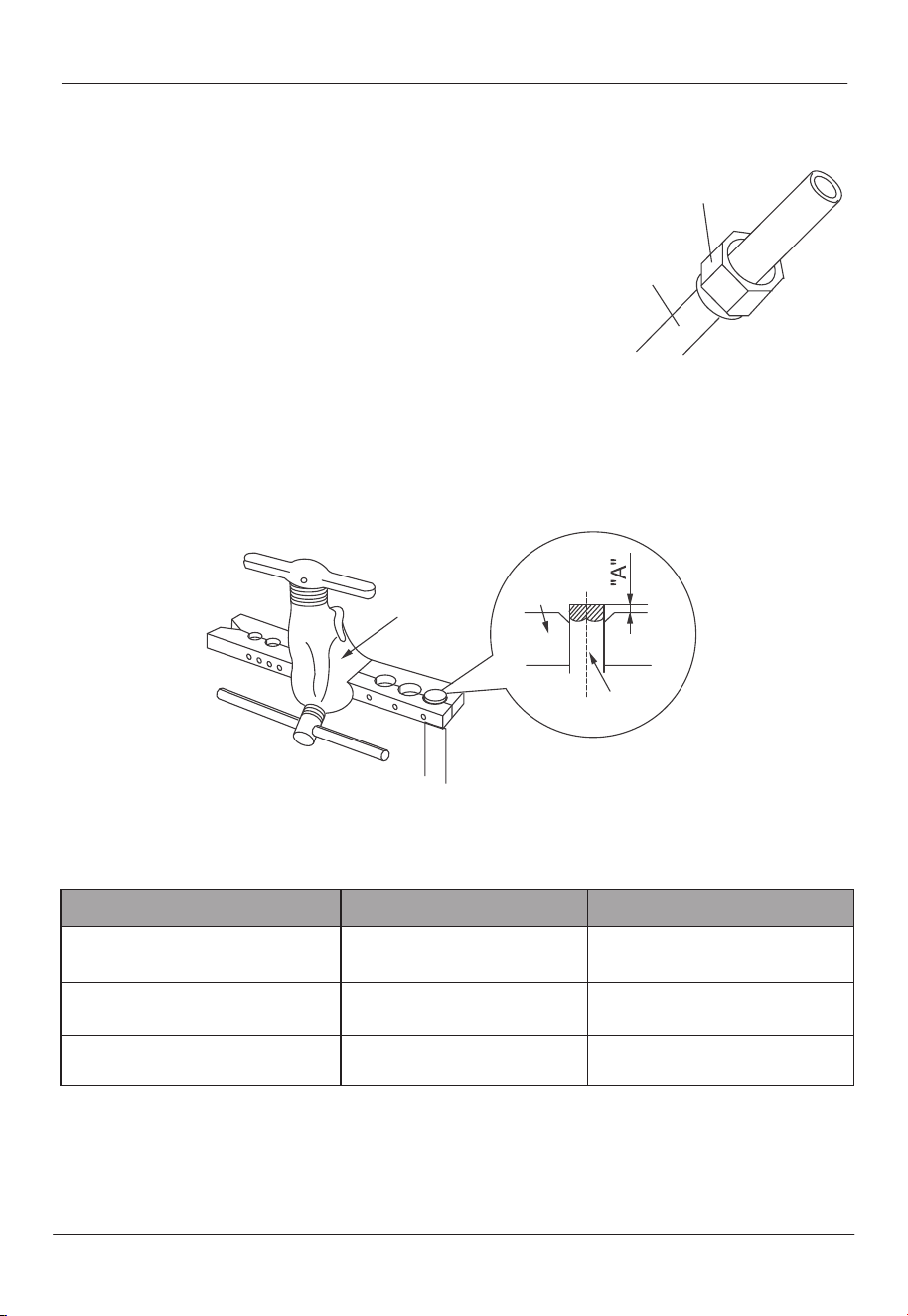
▷ Flare pipe ends
● After removing burrs from the cut pipe, seal the ends
with tape to prevent foreign materials from entering
the pipe.
● Sheath the pipe with insulating material.
● Place flare nuts on both ends of the pipe. Make
sure they are facing in the right direction, because
you can’t put them on or change their direction after flaring.
● Remove the tape from the ends of the pipe when ready to perform flaring
work.
● Clamp flare form on the end of the pipe. Place the flaring tool onto the form.
Turn the handle of the flaring tool clockwise until the pipe is fully flared.
NOTE: The end of the pipe(“A”) must extend beyond the edge of the flare form
in accordance with the dimensions shown in the table below.
Fare nuts
Pipe
Expander
pipe
Refrigerant
Hard
mold
Φ6 - 6.35(1/4")
Φ9 - 9.52(3/8")
Φ12-12.7(1/2")
0.7
1.0
1.0
1.3
1.6
1.8
Maximum A (mm)Outer diameter(mm) Minimum A (mm)
115V unit
230V unit
Between terminal S and L2 is within
0-24V.
Between terminal L1 and G/L2 is
within 100-140V.
Between terminal L2 and G is 0V.
Between terminal S and L2 is
within 0-24V.
Between terminal L1 and L2 is
within 100-140V.
Between terminal S and L2
(connected to the indoor unit) is
within 0-24V.
Between terminal L1/L2 and G is
within 100-140V.
Between terminal L1 and L2 is
200-250V.
Between terminal S and L2 is
within 0-24V.
Between terminal L1 and L2 is
within 200-250V.
Outdoor Unit and Electrical BoxModel Indoor Unit
[email protected] www.turbro.com
24
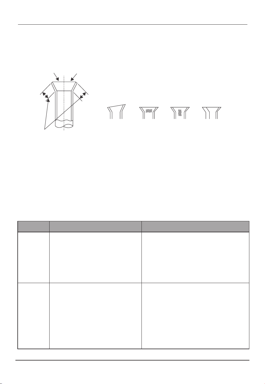
● Remove the flaring tool and flare form, then inspect the end of the pipe for
cracks and even flaring. If there is any blemish, do it again according to the
steps above.
Smooth surface
Improper expanding
The length is equal
Uneven
thickness
Leaning Damaged Crack
surface
▷ Connect pipes
When connecting refrigerant pipes, be careful not to use excessive torque or
to deform the piping in any way. You should first connect the low-pressure pipe,
then the high-pressure pipe.
Step 5: Electrical safety inspection
Check the voltage of wires in the electric box, as well as the indoor and outdoor
unit wiring box.
[email protected] www.turbro.com
25
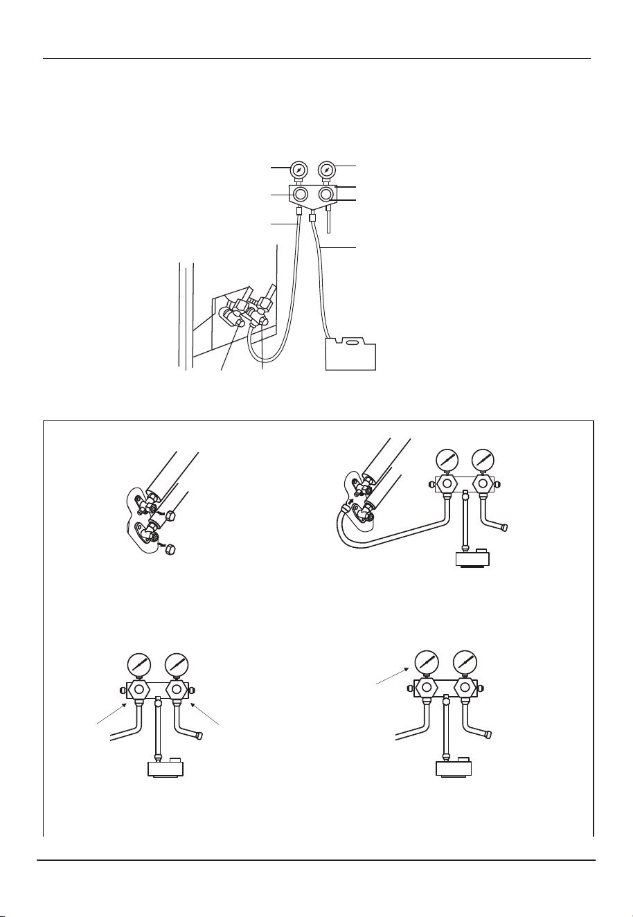
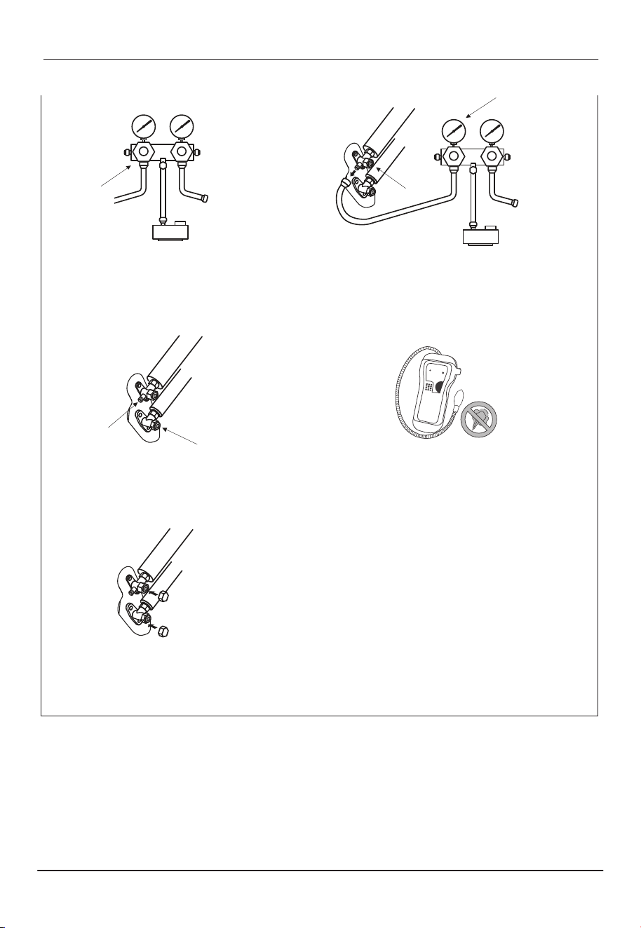
Step 6: Vacuum Pumping
Exclusive R32 refrigerant pumps must be used for R32 refrigerant vacuum.
Compound meter
-76cmHg
Pressure gauge
Manifold valve
Handle Hi
Handle Lo
Charge hose
Charge hose
Vacuum pump
Stop valve
(gas valve)
Stop valve
(liquid valve)
A
Remove the protective caps from
the service port, low-pressure valve,
and high-pressure valve.
C
Open the low-pressure valve, then
close the high-pressure valve.
B
Connect the pressure hose to the service port
and connect the manifold gauge to the vacuum
pump.
D
Turn on the vacuum pump for at least 15 minutes.
Make sure it indicates -0.1 MPa.
[email protected] www.turbro.com
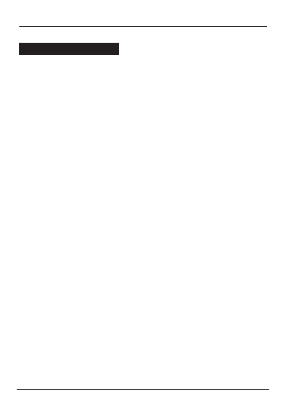
26
E
Close the low-pressure valve then
turn o the vacuum pump. Wait 5
minutes, ensuring that the pressure
change does not exceed 0.005 MPa.
G
Open the high-pressure valve ¼ turn
counterclockwise. Press the service
port for 3 seconds.
I
Fully open the low-pressure valve and
high-pressure valves. Reinstall all
protective caps and valve covers.
F
Open the low-pressure valve for about 10
seconds, then close. Remove the pressure hose
when the pressure indicates above 0.
H
Check if there is any leakage. Refer to the
“refrigerant leakage detection” section on the
next page for more details.
[email protected] www.turbro.com
27
Electrical safety inspection
● Check whether the power supply voltage complies with that on the rating
label.
● Check whether there are any wrong or missing connections between the
power cables, signal cables, and earth cables.
● Check whether the earth resistance and insulation resistance comply with
requirements.
Installation safety inspection
● Confirm the direction of the drainage pipe.
● Confirm that the joint of the refrigerant pipe is installed completely.
● Confirm the safety of the outdoor unit, mounting plate, and indoor unit
installation.
● Confirm that all the valves are fully open.
● Confirm that there are no objects or tools left inside the unit.
● Complete installation of the indoor unit filter and panel.
Refrigerant leakage detection
Check the piping joint, the connector of the two valves of the outdoor unit, the
service port of the gas valve, the welding port, etc., where leakage may occur.
Soapy water detection
Apply soapy water or foam evenly on the parts where leakage may have occurred
and observe whether bubbles appear or not. If not, there is no leakage.
Leak detector method
Use a professional leak detector and read the instructions of operation, detect
the position where leakage may occur. The duration of leak detection for each
position should last for 3 minutes or more.
If the test result shows that there is leakage, the flare nut should be tightened
and tested again until there is no leakage.
After the leak detection is completed, reinstall the valve cover of the outdoor unit.
Inspection Before Use
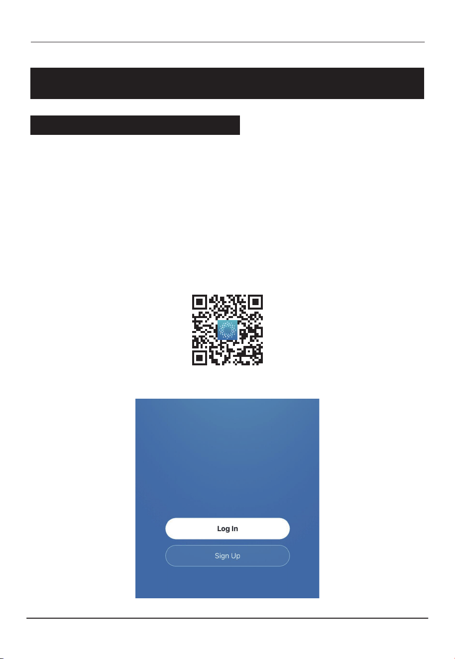
This model is equipped with a Wi-Fi function. Using the APP you can control the
air conditioner via an iPhone or Android smartphone from anywhere, even
outside of your home.
● Supported wireless routers must work with a 2.4G Hz operating frequency.
5.0 GHz frequency is not supported at this time.
● Standard: IEEE 802.11b/g/n20/n40
● Supported smartphone systems: Android 6.0 -13.0, iOS 11.0 - 17.0
a. Scan this QR code and download it.
b.
Launch the app and log in to your account (or sign up for your first use).
[email protected] www.turbro.com
OPERATION
28
Operating from the AIR.ai App
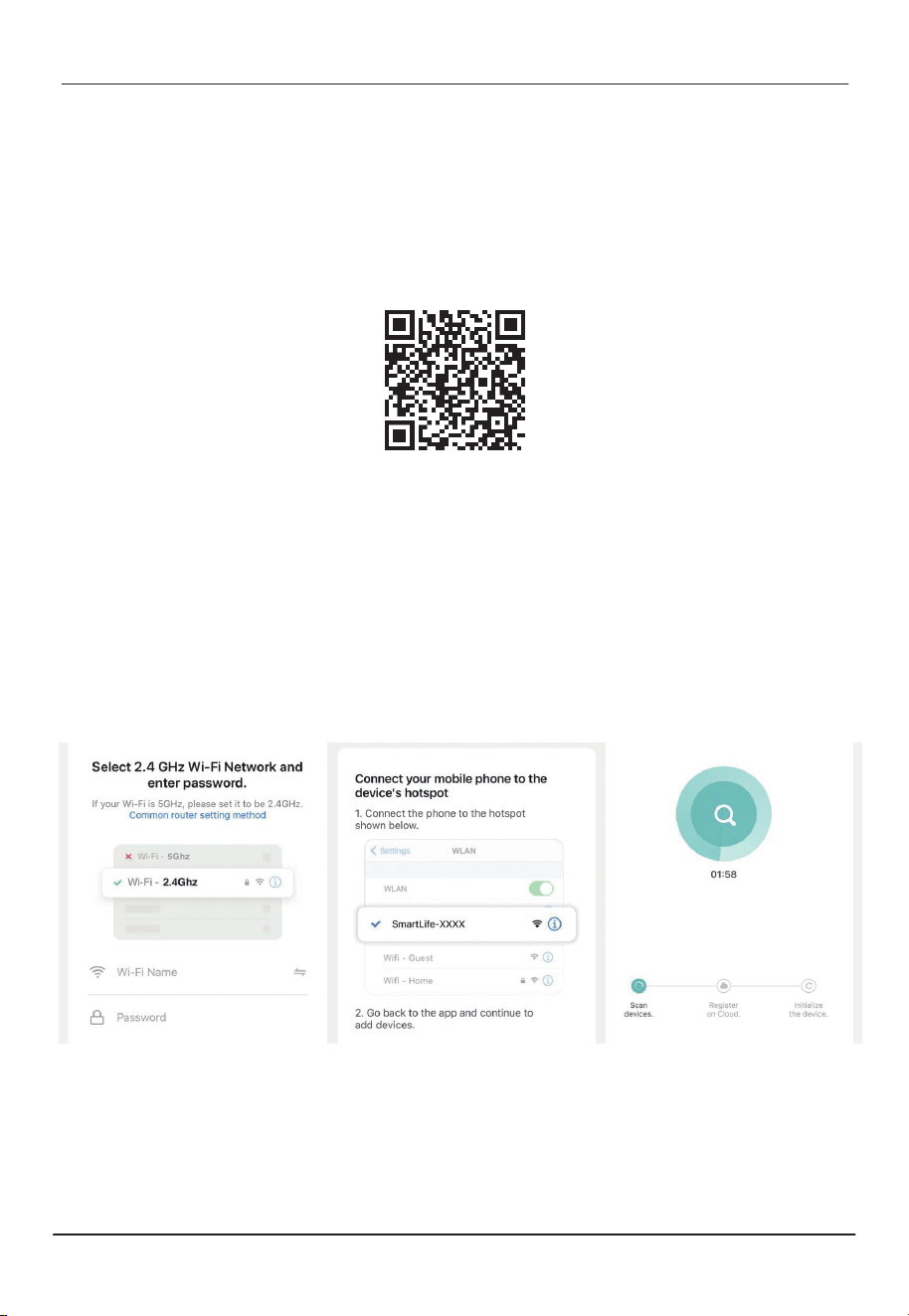
● When the app instruction asks to reset the device, power on the unit, and
long press the “COOL” and “+” buons together on the controller for 5 seconds.
The indoor unit will beep 8 times, then beep twice in 2-second intervals,
which means the WiFi has reset.
● Select the Device named “SmartLife-XXX” in your phone’s wireless seings,
then go back to the app and continue. The app will start to search for your
device. You can see the percent rate of the connecting process.
c. Make sure the unit is powered on, long press the “COOL” and “+” buons
together on the remote control for 5 seconds to switch on the WiFi function.
The unit will beep 8 times, then beep twice in 2-second intervals. Scan the
code below or pasted on the side of the indoor unit to add your device.
Enter the Wi-Fi password and press “Next”.
● If you fail to add the device, please check if your Wi-Fi is 2.4 GHz. If yes, please
try to connect again later, or try another Wi-Fi. 5.0 GHz networks are currently
not supported.
[email protected] www.turbro.com
29
Connect to the unit
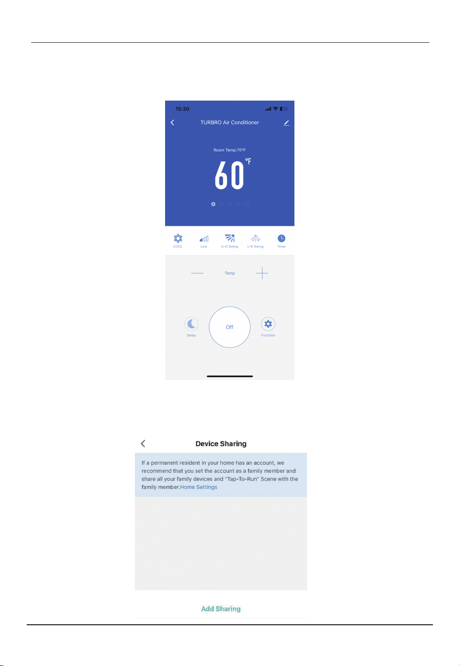
d. Once you have set up the connection, you can name your device and get
started.
Feel free to explore the smart control dashboard. To invite other phones to
control this device, press the buon on upright and go to “Share Device”
- “Add Sharing”.
[email protected] www.turbro.com
30
If you have diiculty connecting to the app, you can reset the Wi-Fi signal as
mentioned above. If you have any questions, please email our support team at
support@turbro.com.
Note:
● The APP is only compatible with smartphones and is not available for laptops
or tablets.
● APP may not support the latest version of Android or iOS systems because of
the test of stability, and may not be compatible with tampered Android or
iOS systems.
● Due to dierent network situations, request time-out could happen, and it is
necessary to do network configuration again.
● Due to dierent network situations, the control process may return time-out
(30S-60S).
● All the illustrations in the manual are for explanation purposes only. The latest
APP may be slightly dierent.
● The APP will continue to be updated with design and content improvements.
Check for updates at the Google Play Store or the APP Store.
Voice Control
You can control the split AC via Alexa or Google Assistant. Follow the instructions
on the App to connect.
[email protected] www.turbro.com
31
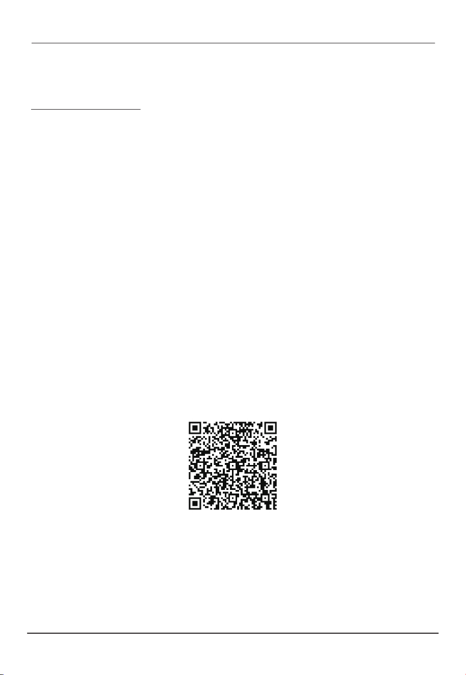
Scan the QR code to find the voice commands.
[email protected] www.turbro.com
33
Turn the air conditioner on/o.ON/OFF
Increase the set temperature; lengthen the time in the
TIMER seing.
+
Decrease the set temperature; reduce the time in the
TIMER seing.
-
FUNCTIONBUTTONS
Select the operation mode.MODE
Switch to the COOL mode.COOL
Adjust the fan speed.SPEED
Switch to the HEAT mode.HEAT
Switch the TIMER function on/o.TIMER
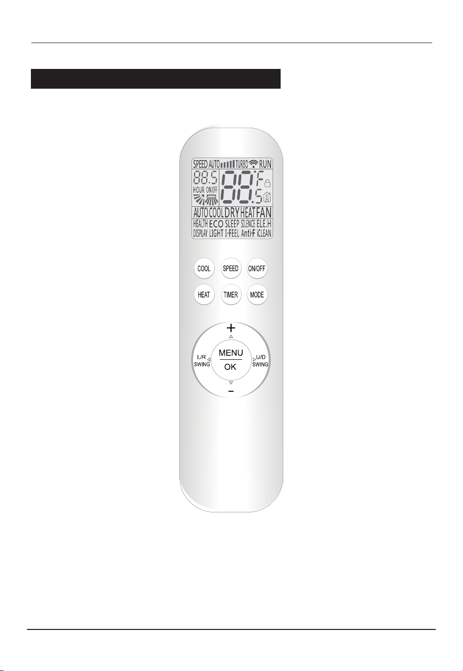
Select the SLEEP / ECO / SILENCE / I-FEEL / Anti-F / iCLEAN /
DISPLAY / LIGHT functions.
MENU/OK
Long press to switch the unit of temperature.COOL + HEAT
Stop/start vertical deflector movement or set the desired
left/right airflow direction.
L/R SWING
Stop/start horizontal deflector movement or set the desired
up/down airflow direction.
U/D SWING
Long press to turn on/o the child lock function.HEAT + MODE
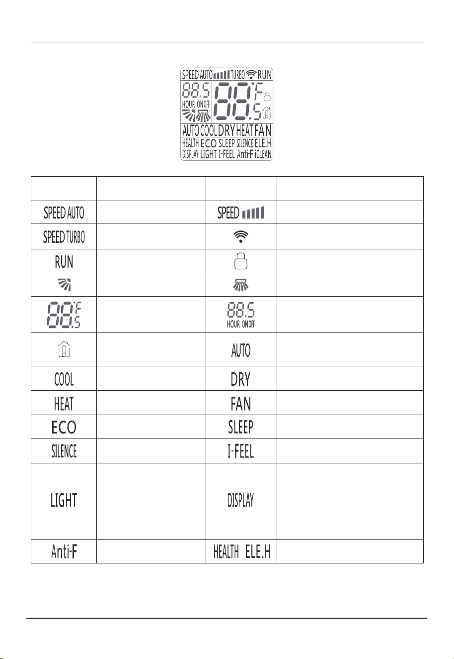
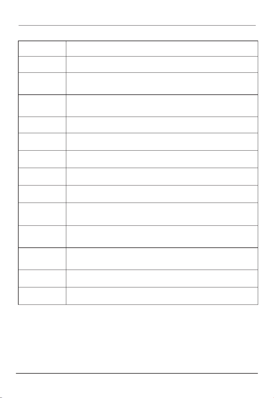
The functions are explained in the “Function Description” section of the user
manual below.
[email protected] www.turbro.com
34
Auto fan speed
Turbo fan speed
The unit is running
Up/down swing
Temperature
COOL mode
HEAT mode
ECO function
SILENCE function
According to the
surrounding light,
automatically turn
o the indoor unit
display
Anti-F function
Indoor ambient
temperature
Left/Right swing
Timer on/o
DRY mode
FAN mode
SLEEP function
I-FEEL function
Turn on/o the indoor
unit display
Not available for this model
AUTO mode
MEANINGSYMBOLS
Fan speed level
Signal
Child lock
MEANINGSYMBOLS
[email protected] www.turbro.com
35
Function Description
ON/OFF Buon
Press this buon to turn on the unit. Press this buon again to turn o the unit.
MODE Buon
Pressing the “Mode” buon will cycle through the following modes, as shown
below:
▷ AUTO MODE
The unit will automatically switch between Cool/Heat or Fan Mode depending
on the ambient room temperature.
● Press the “MODE” buon until the symbol “AUTO” appears on the remote
screen.
● Pressing the “SPEED” buon will adjust the fan speed.
▷ COOL MODE
Ideal for hot muggy weather when you need to cool and dehumidify the room.
● Press the “MODE” buon until the symbol “COOL” appears on the remote
screen.
● Press the “+” or “-” buon to select your desired temperature 60°F-90°F
(16°C-32°C).
● Pressing the “SPEED” buon will adjust the fan speed.
▷ DRY MODE
Ideal to reduce room humidity (spring and autumn, rainy periods, damp rooms,
etc).
● Press the “MODE” buon until the symbol “DRY” appears on the remote
screen.
● In this mode, the fan speed cannot be adjusted. Silence function is not
available.
AUTO COOL DRY
FAN HEAT
[email protected] www.turbro.com
36
▷ HEAT MODE
Ideal for cold weather when you need to heat the room.
● Press the “MODE” buon until the symbol “HEAT” appears on the remote
screen.
● Press the “+” or “-” buon to select your desired temperature 60°F-90°F
(16°C-32°C).
● Press the “SPEED” buon can adjust the fan speed.
Note:
● The fan of the indoor unit will not work immediately when the heating is started
to avoid blowing out cool air.
● In heating mode, the appliance will automatically activate a defrost cycle
when needed. This procedure usually lasts for 5-12 minutes. During defrosting,
the indoor unit fan stops running. Vapor may come out from the outdoor unit
during defrosting. This is not a malfunction. After defrosting, it will resume
heat mode automatically.
▷ FAN MODE
The unit only blows air, with no heating or cooling.
● Press the “MODE” buon until the symbol “FAN” appears on the remote
screen.
● Pressing the “SPEED” buon will adjust the fan speed from LOW-MID-HIGH.
COOL Buon
Press this buon to enter cool mode.
HEAT Buon
Press this buon to enter heat mode.
SPEED Buon
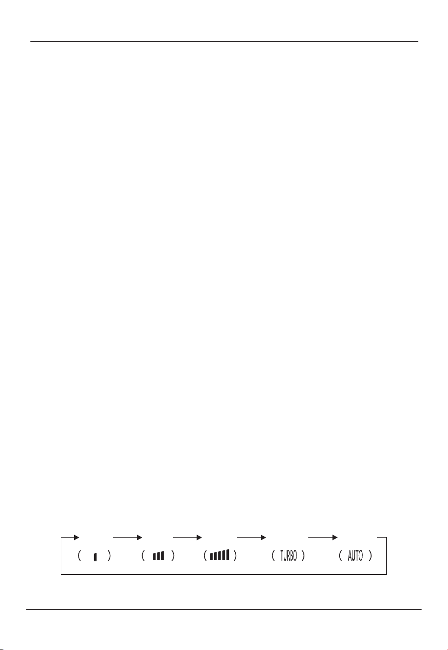
Press this buon, and you can select the fan speed as follows:
Low Mid High
Turbo Auto
[email protected] www.turbro.com
37
Note: The fan speed can only be changed under AUTO / COOL / FAN / HEAT
modes. Auto and Turbo air speed are not available in FAN mode. Turbo
air speed is available under COOL / HEAT mode.
TIMER Buon
This timer can be used to delay the unit start-up or shutdown. This avoids
wasting electricity by optimizing operating periods.
▷ Programming start-up
● When the unit is o, press the “Timer” buon, and the “ON” on the screen will
flash. Press the “+” or “-” buon to set the desired delayed start-up time. The
timer seing increases/decreases by half an hour between 0.5 and 24 hours.
Press the “TIMER” buon again to confirm.
● When the timer is active, “ON” will appear on the remote control.
● After the timer seing, you can continue to set your desired mode and
temperature.
● If you press the timer buon again the timer will be canceled and the display
will disappear.
▷ Programming shut down
● When the unit is on, press the “Timer” buon, and the “OFF” on the screen will
flash. Press the “+” or “-” buon to set the desired delayed shut-down time.
The timer seing increases/decreases by half an hour between 0.5 and 24
hours. Press the “TIMER” buon again to confirm.
● When the timer is active, “OFF” will appear on the remote control.
● If you press the timer buon again the timer will be canceled and the display
will disappear.
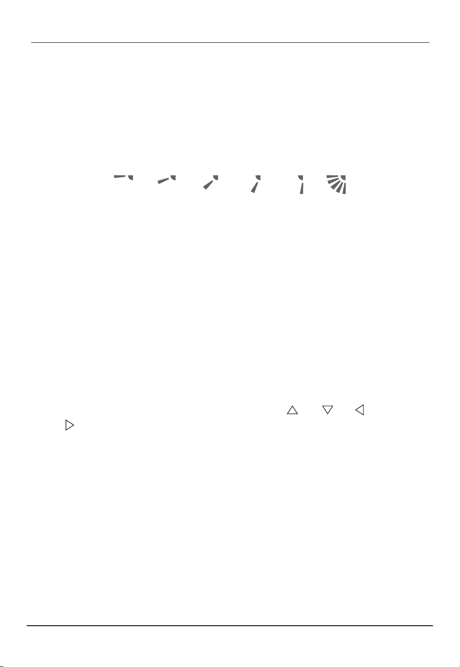
L/R SWING Buon
This function is useful for adjusting the left/right swing of air circulation.
● Press the buon to activate the deflector to swing from left to right. Press the
buon again to stop the swing movement at the current angle.
U/D SWING Buon
This function is useful for adjusting the up/down swing of air circulation.
[email protected] www.turbro.com
38
● Press the buon to activate the deflectors to swing from up to down. Press
the buon again to stop the swing movement at the current angle.
▷ Rated Swinging
● When the unit is on, long press the “U/D SWING” buon for 3 seconds, the
buon will shift to “Rated swinging”, and then you can press the “U/D SWING”
buon to select the deflector position.
● Long press the buon again for 3 seconds to cancel Rated swinging.
Note:
● Never put fingers, sticks, or other objects into the air inlet or outlet vents as
this may cause damage or injury.
● In heating mode, pressing the “U/D SWING” buon will activate the deflector
to swing up/down after a few minutes to make sure blowing warm wind to you.
MENU Buon
▷ SLEEP Function
This function is useful at night as it maintains the room at optimum temperature
silently without excessive fluctuations in either temperature or humidity.
● Press the “MENU” buon to enter the function selection.
● Then choose the “SLEEP” mode by pressing the (+), (-), (L/R SWING),
and (U/D SWING).
● When the “SLEEP” character blinks, press the “OK” buon to switch on this
function. The “SLEEP” icon will be indicated on the remote screen.
● Choose “SLEEP” again and press “OK” to cancel this function.
Note:
● When in COOL/DRY mode, the temperature will increase by 2°F for the first
two hours under the sleep function, then the temperature remains at this
temp. At the 7th and 10th hour, the unit will automatically decrease by 2°F and
quit sleep mode.
● Sleep function is available only on COOL / HEAT / DRY modes. In this mode, the
fan speed is always low.
[email protected] www.turbro.com
39
● The display of the indoor unit will be o when the sleep function is activated.
● If you change the mode, you need to set the sleep function again.
▷ ECO Function
In this function, the unit will enter the ECO mode which consumes the least
electricity, and exit it automatically 8 hours later. This function is only available
in COOL mode.
● Switch to COOL mode, press the “MENU” buon to enter the function
selection.
● Then choose the “ECO” mode by pressing the (+), (-), (L/R SWING),
and (U/D SWING).
● When the “ECO” character blinks, press the “OK” buon to switch on this
function. The “ECO” icon will be indicated on the remote screen.
● Choose “ECO” again and press “OK” to cancel this function. Changing the mode
or turning o the unit will automatically quit the ECO function.
▷ SILENCE Function
● Press the “MENU” buon to enter the function selection.
● Then choose the “SILENCE” mode by pressing the (+), (-), (L/R SWING),
and (U/D SWING).
● When the “SILENCE” character blinks, press the “OK” buon to switch on this
function. The “SILENCE” icon will be indicated on the remote screen.
● Choose “SILENCE” again and press “OK” to cancel this function.
● This function is not available in DRY mode.
▷ I-FEEL Function
This function enables the remote control to measure the temperature at its
current location and send this signal to the air conditioner to optimize the
temperature around you to ensure comfort.
● Press the “MENU” buon to enter the function selection.
● Then choose the “I-FEEL” mode by pressing the (+), (-), (L/R SWING),
and (U/D SWING).
● When the “I-FEEL” character blinks, press the “OK” buon to switch on this
function. The “I-FEEL” and “ ” icons will be indicated on the remote screen.
[email protected] www.turbro.com
40
● The temperature on the screen with “ ” is the ambient temperature. You
can press “+”/ “-” to set the desired temperature which will flash and then the
screen will show the ambient temperature again.
● Choose “I-FEEL” again and press “OK” to cancel this function.
▷ Anti-F Function
Use this funciton to remove the moisture within the evaporator to prevent it
from giving o a bad smell from mold.
● Turn o the unit, press the “MENU” buon to enter the function selection.
● Then choose the “Anti-F” mode by pressing the (+), (-), (L/R SWING),
and (U/D SWING).
● When the “Anti-F” character blinks, press the “OK” buon to switch on this
function. The “Anti-F” icon will be indicated on the remote screen and it will
beep 5 times.
● When the unit is turned o under COOL / DRY / AUTO (cooling) mode, it will
continue to operate for 3 minutes.
● Power o the unit. Choose “Anti-F” again and press “OK” to cancel this
function and the buzzer will beep 5 times.
Note: With Anti-F activated, it is not advised to turn on the unit again before it
is fully OFF.
Once set the function is also available for the next powering o until you
cancel it.
▷ iCLEAN Function
This mode will clean the dust o the evaporator and dry it to increase the cooling
and heating eiciency.
● Turn o the unit, press the “MENU” buon to enter the function selection.
● Then choose the “iCLEAN” mode by pressing the (+), (-), (L/R SWING),
and (U/D SWING).
● When the “iCLEAN” character blinks, press the “OK” buon to switch on this
function. The “iCLEAN” icon will indicate on the remote screen and the indoor
unit will display "CL".
● The iCLEAN function will immediately run within an hour. If the unit is turned on
within an hour, the iCLEAN function will be deactivated.
[email protected] www.turbro.com
41
● Power o the unit. Choose “iCLEAN” again and press “OK” to cancel this
function.
Note:
● If the unit is turned on within an hour, the iCLEAN function will be deactivated.
● The iCLEAN function works immediately when seing. You need to set it again
for the next use.
▷ DISPLAY Function
Switch the LED display ON/OFF on the indoor unit panel.
● Press the “MENU” buon to enter the function selection.
● Then choose the “DISPLAY” mode by pressing the (+), (-), (L/R SWING),
and (U/D SWING).
● When the “DISPLAY” character blinks, press the “OK” buon to switch o the
LED display on the panel. Choose “DISPLAY” again and press “OK” to switch on
the LED display.
▷ LIGHT Function
● The unit will automatically activate or deactivate the display on the indoor
unit according to the indoor ambient brightness.
● Press the “MENU” buon to enter the function selection.
● Then choose the “LIGHT” mode by pressing the (+), (-), (L/R SWING),
and (U/D SWING).
● When the “LIGHT” character blinks, press the “OK” buon to switch on this
function. The “LIGHT” icon will be indicated on the remote screen.
● Choose “LIGHT” again and press “OK” to cancel this function.
°C/°F
Long press the “COOL” and “HEAT” buons for 3 seconds to switch the
temperature between Fahrenheit and Celsius.
Child Lock
● Long press the “HEAT” and “MODE” buons for 3 seconds to switch on/o the
child-lock function.
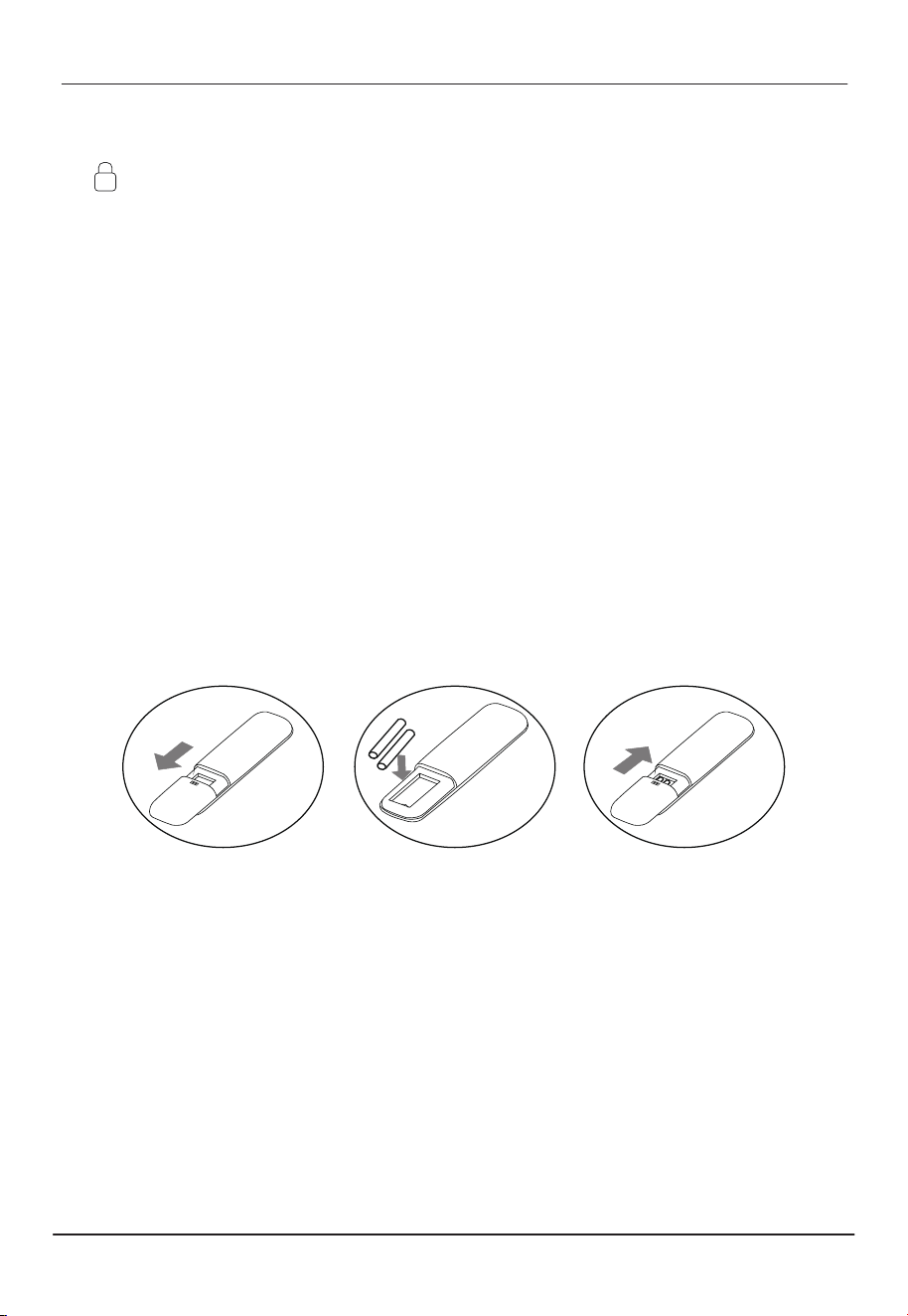
● Remove the cover on the rear of the remote control.
● Insert two "AAA" 1.5V baeries in the correct position (see instructions inside
the baery compartment).
Note:
● If the remote control does not work normally, remove the baeries for 30
seconds before reinstalling them. If that doesn’t work, replace the baeries.
● If the remote control unit is replaced or disposed of, the baeries must be
removed and discarded in accordance with current legislation as they are
harmful to the environment.
[email protected] www.turbro.com
42
● When the child-lock function is activated, the remote screen will indicate
“ ” and will not send any signal to the air conditioner.
Filter Clean Reminder
● When the unit is on, press the U/D SWING Buon 6 times in 3 seconds to
switch on this function. The unit will beep 6 times.
● The indoor unit display will flash 5 times after turning o the unit to remind
you to check and clean the filter.
Using the Remote
● The max range of the remote is 26 ft/8 m away from the unit.
● Check that there are no objects between the remote control and the signal
receptor in the indoor unit.
● Never leave the remote control exposed to the sun.
● Keep the remote control at a distance of at least 1m from the television or other
electrical appliances.
Inserting or Replacing the Baeries
[email protected] www.turbro.com
43
● Do not mix old and new baeries. Do not mix alkaline, standard (carbon-zinc)
or rechargeable (nickel-cadmium) baeries.
● Do not dispose of baeries in fire. Baeries may explode or leak.
● Remove the baeries if the remote control won’t be used for a long time.
● When cleaning, you must shut down the machine and cut o the power supply
for more than 5 minutes.
● Under no circumstances should the air conditioner be flushed with water.
● Volatile liquid (e.g. thinner or gasoline) will damage the air conditioner, so only
use a soft dry cloth or wet cloth dipped with neutral detergent to clean the air
conditioner.
● Pay aention to cleaning the filter regularly to avoid dust accumulation
which will aect the filter eect. It’s recommended to clean the filter every
3-6 months. When the operating environment is dusty, the cleaning frequency
should be increased appropriately.
● After removing the filter, do not touch the fins of the indoor unit to avoid injury
or damage.
CLEANING
Warning
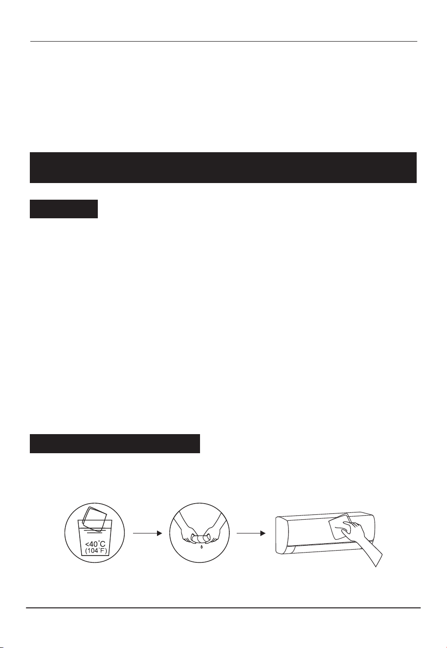
If there’s dust on the surface of the outer case, gently wipe it with a soft cloth.
Do not remove the panel during cleaning.
Cleaning the Outer Case
[email protected] www.turbro.com
44
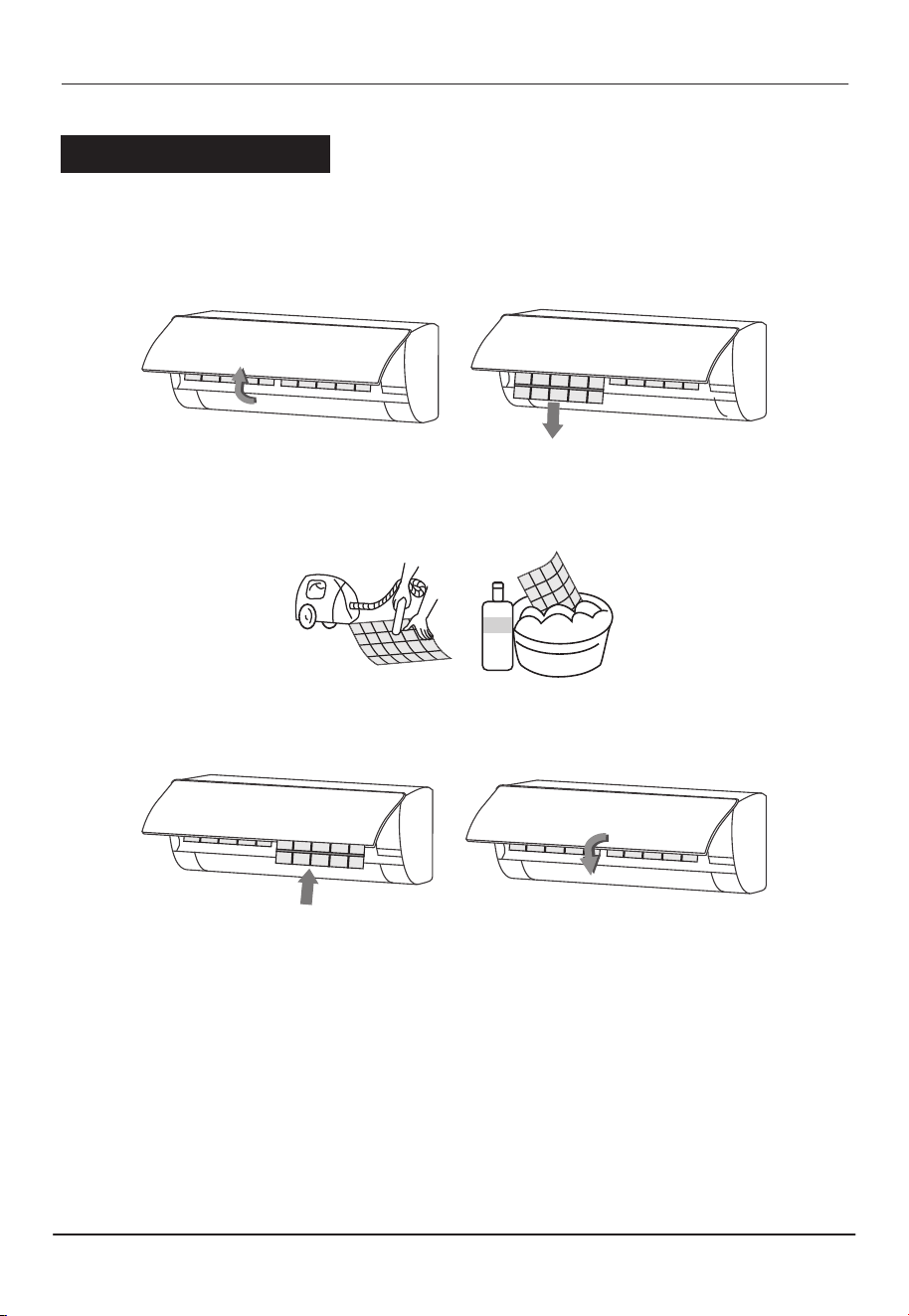
● Use both hands to open the panel at an angle from both ends of the panel
following the direction of the arrow.
● Release the air filter from the slot and remove it.
● Clean the filter with soapy water and air dry it. If the filter is very dirty, clean it
with warm water (below 113°F/45°C) with mild detergent, and put the filter in
the shade to dry in the air.
Cleaning the Filter
● Reinstall the dried filter in reverse order of removal, then cover and lock the
panel.
Note:
● Please clean the filter in time to ensure clean, healthy, and eicient operation
inside the air conditioner.
● Do not touch the metal fins in the air conditioner after removing the filter, as
they may cause personal injury.
● Do not aempt to dry the filter with a hair dryer or other heating elements as
this may deform or ignite the filter.
● Do not operate the air conditioner if the air filter is missing.
[email protected] www.turbro.com
45
Maintenance Checklists
Pre-Season Maintenance Checklist
● Check whether there are obstacles at the air inlet and outlet of indoor and
outdoor units.
● Clean the filter.
● Install the baeries of the remote control and check whether the power is on.
● Check whether the drain pipe is unobstructed.
Post-Season Maintenance Checklist
● Clean the filter.
● Take out the baeries of the remote control.
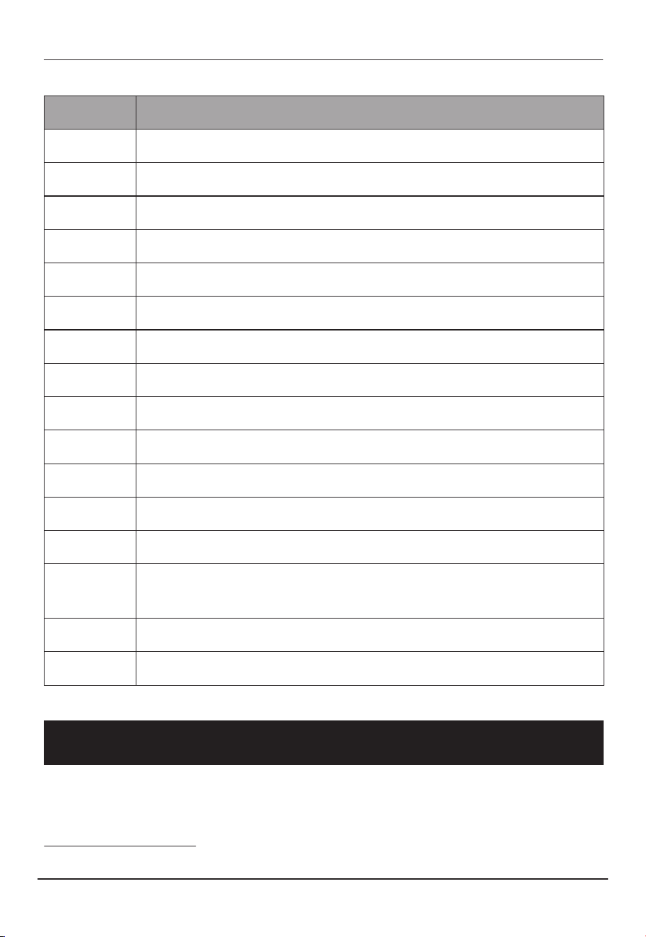
IDU overcurrent protection
IDU room sensor error
ODU condenser sensor error
IDU evaporator sensor error
AC or DC motor error
ODU and IDU communication error
Communication fault between display board and PCB board
IDU PCB EE error
E0
E1
E2
E3
E4
E5
E8
Eb
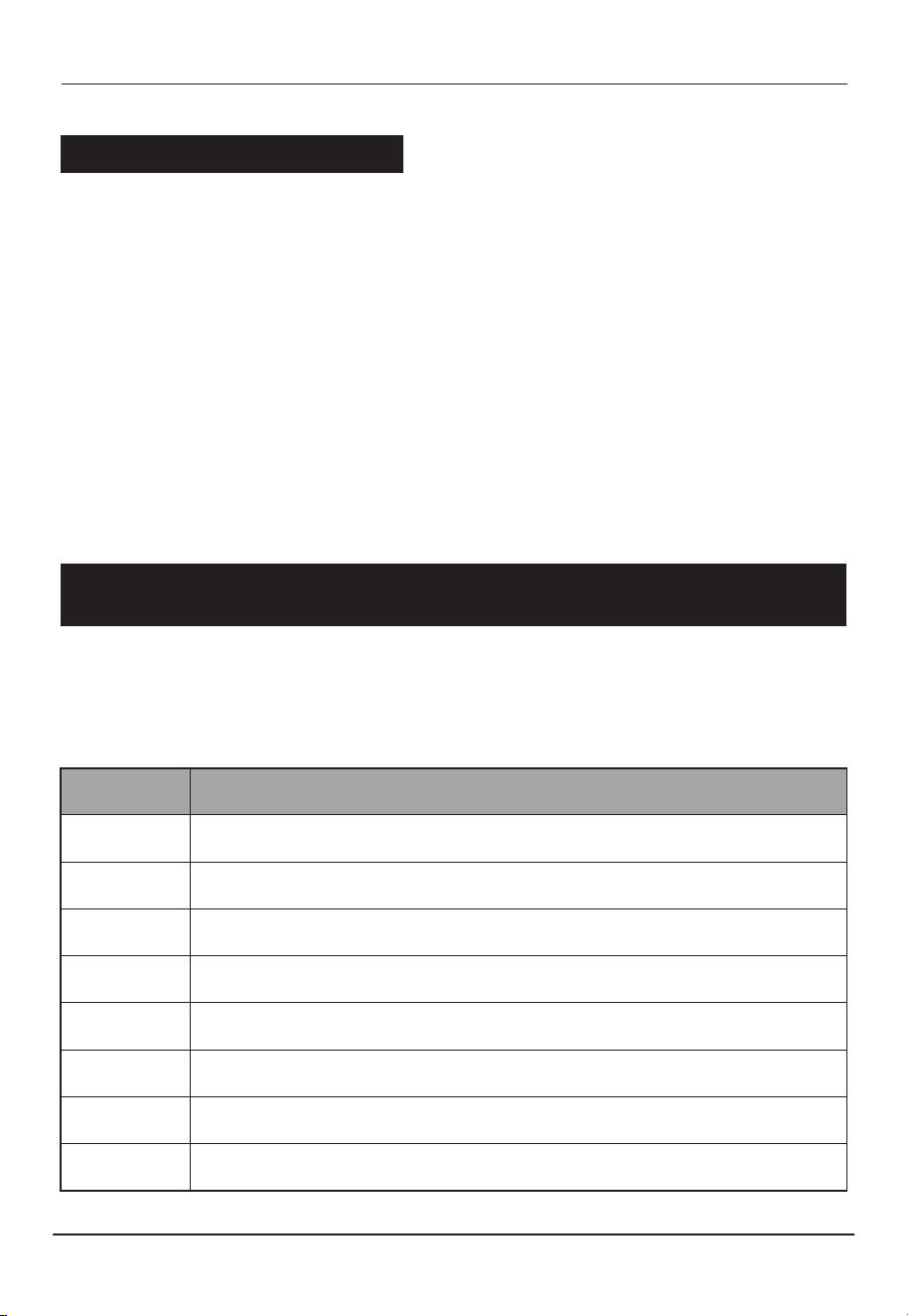
MALFUNCTION NAMEDISPLAY
The unit has a self-diagnosis system to identify malfunctions. Malfunction codes
will be displayed on the indoor unit display. If this is displayed, contact TURBRO
service team.
MALFUNCTION CODES
[email protected] www.turbro.com
46
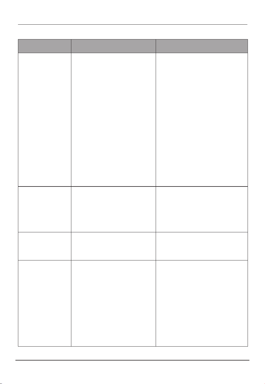
MALFUNCTION NAMEDISPLAY
High-pressure switch protection
Lack of refrigerant protection
Condenser overload protection (Cooling mode)
Discharge temperature protection
Evaporator overload protection (Heating mode)
IDU anti-freezing protection (Cooling mode)
ODU overcurrent protection
ODU fan motor error
ODU module protection error
P2
P3
P4
P5
P6
P7
P8
F0
F1
ODU PFC Protection error
Compressor start failure or out-of-step error
ODU discharge sensor error
ODU room sensor error
ODU communication error between main PCB board and
module board
ODU PCB EE error
F2
F3
F4
F6
F8
F9
Suction senser errorFA
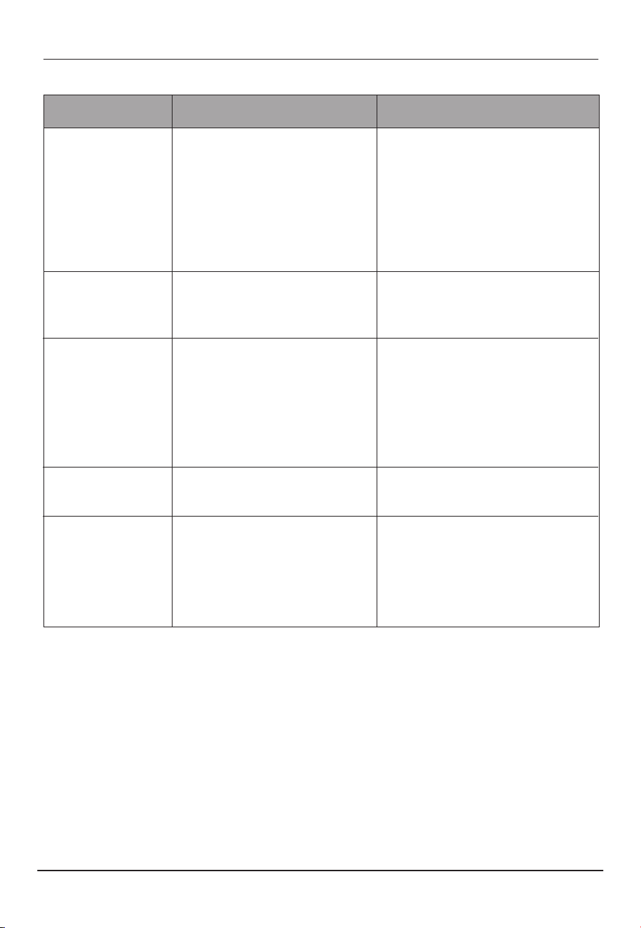
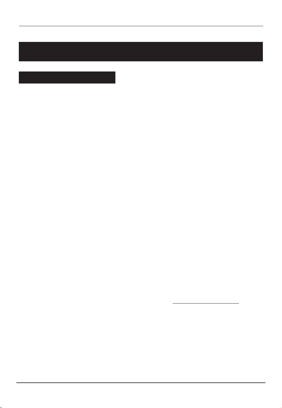
Troubleshoot your problem by using the chart below. If the air conditioner still
does not work properly, please contact TURBRO customer team via
support@turbro.com.
TROUBLESHOOTING
[email protected] www.turbro.com
47
The appliance
does not operate
A. Incorrect connections of
cable or electric wires.
B. Have set a delayed start-up
time.
C. It sometimes stops
operating to protect the
appliance.
D. Voltage is higher or lower
than the rated voltage
range.
E. Control Board/Fan motor
Damaged.
F. The air conditioner can’t run
after the immediate start
-up after it is shut down.
A. Check and reconnect the
wires correctly.
B. Cancel the TIMER function.
C. Wait for 30 minutes and try
again. If the problem persists,
contact the TURBRO customer
service team.
D. Check and make sure the
supply voltage is stable and
consistent with the rated
range.
E. Contact the TURBRO
customer service team.
F. The protective delay switch
will delay the operation for
3-5 minutes.
POSSIBLE CAUSE POSSIBLE REMEDYISSUE
The air
conditioner stops
running after it
starts up for a
while.
A. The unit reached the
seing temperature.
B. It’s defrosting.
C. Have set a shutdown timer.
A. It is normal.
B. It will automatically restore
and run again after defrosting.
C. Turn on the unit again to use.
No air is blowing
from the air
conditioner
Air outlet/Inlet is blocked.
Check and remove the
obstacles blocking the air
outlet/inlet.
Insuicient airflow,
either hot or cold
A. Air filter is blocked by dust.
B. Unsuitable temperature
seing.
C. Other sources of heat in
the room.
D. The windows, doors, and/or
curtains are not closed.
E. No refrigerant.
A. Clean the air filter.
B. Adjust the temperature
seing and mode.
C. Remove the heat sources if
possible.
D. Make sure all the doors,
windows, and curtains are
closed.
E. Contact qualified professionals
to refill the refrigerant.
[email protected] www.turbro.com
48
Strange noise
A. Has the unit just been
turned on/o or adjusted
temperature?
B. Too much dust
accumulation on the air
filter of the indoor.
A. This sound is made by the
expansion or contraction of
the front panel due to
temperature variations and
does not indicate a problem.
B. Clean the air filter.
Produces a
gurgling sound
Has the unit just been turned
on?
Backflow of liquid in the
refrigerant circulation
There are water
drops over the
surface of the
indoor unit.
A. Long cooling run in open
space produces water
drops.
B. Too small opening angle of
the louver blades.
A. Close the doors and windows.
B. Set a larger angle for the
louver blades.
POSSIBLE CAUSE POSSIBLE REMEDYISSUE
The appliance
does not respond
to commands
A. Remote control is not close
enough to the indoor unit.
B. The baeries of the remote
control need to be replaced.
C. Obstacles between the
remote control and signal
receiver of the indoor unit.
A. Stand closer in front of the
indoor unit.
B. Replace with two new
AAA(1.5V) baeries.
C. Remove the obstacles.
Strange odor
Check whether there’s an
odor source such as new
furniture
Remove the odor source and
clean the filter
If you notice or experience any of the following conditions, please turn o the
air conditioner, disconnect from power, discontinue use, and contact support
immediately.
● Strange noises during operation.
● Faulty electronic control board.
● Faulty fuses or switches.
● Spraying water or objects inside the appliance.
● Very strong smells coming from the appliance.
TURBRO provides a 5-year limited warranty for TURBRO products from the date
of purchase, subject to the following conditions and limitations outlined below.
What is covered?
● This warranty is limited to the replacement of part(s) proved to be defective
in material or workmanship, after said defect is confirmed by the manufacturer’s
inspection.
● The manufacturer may, at its discretion, fully discharge all obligations with
respect to this warranty by refunding the wholesale price of the defective
part(s).
What is not covered?
● Damage caused by the owner when aempting to fix or alter the product
themselves.
● Damage caused by misuse, abuse, neglect, alterations, or unauthorized repair.
● Natural depreciation.
● Any alteration misuse of the product will nullify this warranty.
● This warranty is non-transferable, which is eective for the original buyer from
the authorized seller only.
How to request warranty services?
● To obtain the benefit of this warranty, please leave a message online
(www.turbro.com/contact), or send an email to [email protected]om.
What will TURBRO do?
● Replace the item if not repairable.
● Refund the item under certain circumstances.
[email protected] www.turbro.com
WARRANTY & CUSTOMER SUPPORT
49
Warranty Information
[email protected] www.turbro.com
50
Customer Support
We are here to help anytime!
Any problems, write to us via support@turbro.com. We will get back to you
within 1 business day.
www.turbro.com