R32
OUTDOOR UNIT
ENGINEERING MANUAL
MULTI
F
MAX
MULTI
F
Multi-Zone Heat Pump Outdoor Units
1.5 to 4 Tons
Dual-, Tri-, and
Quad-Zone Multi F
Five, Six, and Eight-Zone
Multi F MAX
WITH

For continual product development, LG Electronics U.S.A., Inc., reserves the right to change specifications without notice.
© LG Electronics U.S.A., Inc.
This document, as well as all reports, illustrations, data, information, and other materials are the property of LG Electronics U.S.A., Inc.
PROPRIETARY DATA NOTICE
This document, as well as all reports, illustrations, data, information,
and other materials are the property of LG Electronics U.S.A., Inc., and are
disclosed by LG Electronics U.S.A., Inc. only in confidence.
This document is for design purposes only.
A summary list of safety precautions is on page 4.
For more technical materials such as submittals, catalogs, installation,
owner’s, and service manuals, visit www.lghvac.com.
Proper sizing and installation of equipment is critical to achieve optimal performance. Split system air conditioners and heat pumps
(excluding ductless systems) must be matched with appropriate coil components to meet ENERGY STAR
®
criteria. Ask your contractor for
details or visit www.energystar.gov.
(ENERGY STAR and the ENERGY STAR mark are registered trademarks owned by the U.S. Environmental Protection Agency.)

'XHWRRXUSROLF\RIFRQWLQXRXVSURGXFWLQQRYDWLRQVRPHVSHFL¿FDWLRQVPD\FKDQJHZLWKRXWQRWL¿FDWLRQ
©
/*(OHFWURQLFV86$,QF(QJOHZRRG&OLIIV1-$OOULJKWVUHVHUYHG³/*´LVDUHJLVWHUHGWUDGHPDUNRI/*&RUS
3
R32 Multi F and Multi F MAX with LGRED° Outdoor Unit Engineering Manual
MULTI
F
MAX
MULTI
F
WITH
TABLE OF CONTENTS
Unit Nomenclature .......................................................................................................................................................................................................... 5
LG Air Conditioner Technical Solution (LATS) ......................................................................................................................................................... 6-7
Manual Equipment Selection Procedure ................................................................................................................................................................ 8-14
Multi F with LGRED Outdoor Unit Product Data ................................................................................................................................................... 15-29
0HFKDQLFDO6SHFL¿FDWLRQV .............................................................................................................................................................................................. 16
*HQHUDO'DWD ............................................................................................................................................................................................................. 17-19
(OHFWULFDO'DWD ................................................................................................................................................................................................................ 20
)XQFWLRQV&RQWUROV2SWLRQVDQG$FFHVVRULHV .............................................................................................................................................................. 21
'LPHQVLRQV ..................................................................................................................................................................................................................... 22
&HQWHURI*UDYLW\&RUQHU:HLJKWV ................................................................................................................................................................................ 23
:LULQJ'LDJUDP ............................................................................................................................................................................................................... 24
5HIULJHUDQW)ORZ'LDJUDPV ........................................................................................................................................................................................ 25-27
$FRXVWLF'DWD ............................................................................................................................................................................................................ 28-29
Multi F MAX with LGRED Outdoor Unit Product Data .......................................................................................................................................... 30-42
0HFKDQLFDO6SHFL¿FDWLRQV .............................................................................................................................................................................................. 31
*HQHUDO'DWD ............................................................................................................................................................................................................. 32-33
(OHFWULFDO'DWD ................................................................................................................................................................................................................ 35
)XQFWLRQV&RQWUROV2SWLRQVDQG$FFHVVRULHV .............................................................................................................................................................. 36
'LPHQVLRQV ..................................................................................................................................................................................................................... 37
&HQWHURI*UDYLW\&RUQHU:HLJKW .................................................................................................................................................................................. 38
:LULQJ'LDJUDPV ............................................................................................................................................................................................................. 39
5HIULJHUDQW)ORZ'LDJUDPV ............................................................................................................................................................................................. 40
$FRXVWLF'DWD ............................................................................................................................................................................................................ 41-42
Multi F MAX BD Unit Product Data ........................................................................................................................................................................ 43-50
0HFKDQLFDO6SHFL¿FDWLRQV .............................................................................................................................................................................................. 44
*HQHUDO'DWD .................................................................................................................................................................................................................. 45
'LPHQVLRQV ..................................................................................................................................................................................................................... 46
:LULQJ'LDJUDP ............................................................................................................................................................................................................... 47
5HIULJHUDQW)ORZ'LDJUDP ............................................................................................................................................................................................... 48
<%UDQFK$FFHVVRU\ ........................................................................................................................................................................................................ 49
%UDQFK'LVWULEXWLRQ8QLW2ULHQWDWLRQ ............................................................................................................................................................................... 50
Electrical Connections ............................................................................................................................................................................................ 51-58
*HQHUDO,QIRUPDWLRQ ........................................................................................................................................................................................................ 52
:LULQJ6SHFL¿FDWLRQV ................................................................................................................................................................................................. 53-54
6\VWHPVIRU0XOWL) ......................................................................................................................................................................................................... 55
6\VWHPVIRU0XOWL)0$; ................................................................................................................................................................................................ 56
,QGRRU8QLWV&RQWUROOHUV ........................................................................................................................................................................................... 57-58
Piping Limitation and Placement Considerations ................................................................................................................................................ 59-72
3LSLQJ/LPLWDWLRQV ...................................................................................................................................................................................................... 60-61
6HOHFWLQJWKH%HVW/RFDWLRQIRUWKH2XWGRRU8QLW ...................................................................................................................................................... 62-64
2XWGRRU8QLW&OHDUDQFH5HTXLUHPHQWV ..................................................................................................................................................................... 65-67
,QVWDOOLQJ2XWGRRU8QLWV,QGRRUV ................................................................................................................................................................................ 68-70
6HOHFWLQJWKH%HVW/RFDWLRQIRUWKH,QGRRU8QLWV ............................................................................................................................................................ 71
6HOHFWLQJWKH%HVW/RFDWLRQIRU%UDQFK'LVWULEXWLRQ8QLWV ......................................................................................................................................... 71-72
Limited Warranty .......................................................................................................................................................................................................... 73
'XHWRRXUSROLF\RIFRQWLQXRXVSURGXFWLQQRYDWLRQVRPHVSHFL¿FDWLRQVPD\FKDQJHZLWKRXWQRWL¿FDWLRQ
©
/*(OHFWURQLFV86$,QF(QJOHZRRG&OLIIV1-$OOULJKWVUHVHUYHG³/*´LVDUHJLVWHUHGWUDGHPDUNRI/*&RUS
4
R32 Multi F and Multi F MAX with LGRED° Outdoor Unit Engineering Manual
MULTI
F
MAX
MULTI
F
WITH
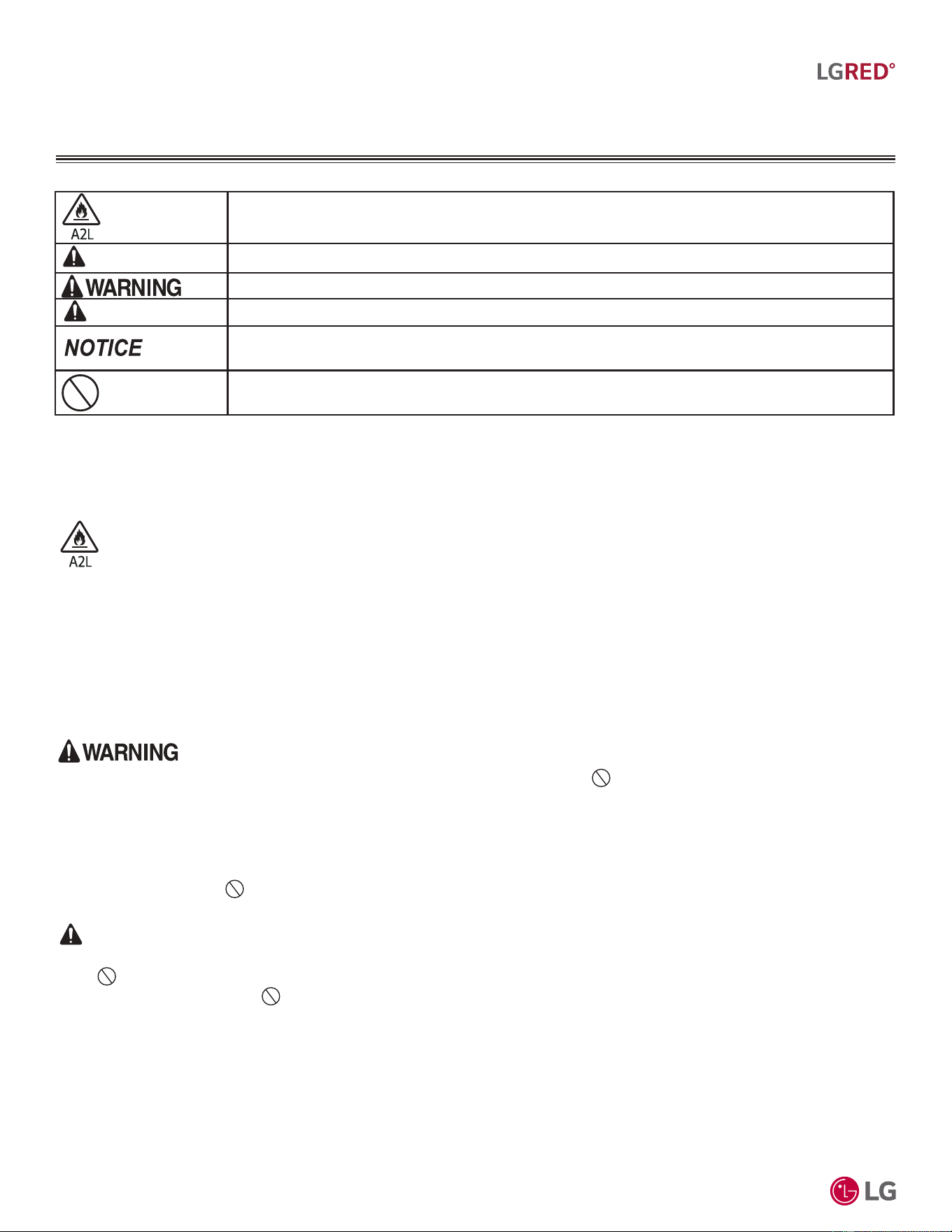
TABLE OF SYMBOLS
,QGLFDWHVWKDWWKLVDSSOLDQFHXVHVDÀDPPDEOHUHIULJHUDQW,IWKHUHIULJHUDQWOHDNVDQGLVH[SRVHGWRDQH[WHUQDO
LJQLWLRQVRXUFHWKHUHLVDULVNRI¿UH
,QGLFDWHVDKD]DUGRXVVLWXDWLRQWKDWLIQRWDYRLGHG:,//5(68/7,1'($7+256(5,286,1-85<
1
,QGLFDWHVDKD]DUGRXVVLWXDWLRQWKDWLIQRWDYRLGHG&28/'5(68/7,1'($7+256(5,286,1-85<
1
,QGLFDWHVDKD]DUGRXVVLWXDWLRQWKDWLIQRWDYRLGHG&28/'5(68/7,10,1252502'(5$7(,1-85<
1
,QGLFDWHVLQIRUPDWLRQFRQVLGHUHGLPSRUWDQWEXWQRWKD]DUGUHODWHGLQGLFDWHVVLWXDWLRQVWKDWPD\UHVXOWLQHTXLSPHQW
RUSURSHUW\GDPDJHDFFLGHQWV
1
7KLVV\PEROLQGLFDWHVDQDFWLRQWKDWVKRXOGQRWEHSHUIRUPHG
DANGER
CAUTION
1
6LJQDOZRUGVV\PEROVDQGGH¿QLWLRQVWDNHQIURP$PHULFDQ1DWLRQDO6WDQGDUGV,QVWLWXWH$16,=6HHKWWSVZZZDQVLRUJIRUPRUH
LQIRUPDWLRQ
/*(OHFWURQLFVSOLWV\VWHPKHDWLQJDQGDLUFRQGLWLRQLQJ+9$&SURGXFWVQRZFRQWDLQ5UHIULJHUDQW:KLOH5UHIULJHUDQWLVVOLJKWO\ÀDPPDEOHLW
KDVDKLJKHUHI¿FLHQF\DORZHU*OREDO:DUPLQJ3RWHQWLDO*:3YDOXHDQGLVPRUHHQYLURQPHQWDOO\IULHQGO\WKDQ5$
52]RQH'HSOHWLRQ3RWHQWLDO2'39DOXH
5*OREDO:DUPLQJ3RWHQWLDO*:39DOXH
7KHDPRXQWRIUHIULJHUDQWGHSHQGVRQRXWGRRUXQLWWRLQGRRUXQLWFRQ¿JXUDWLRQ$OOUHIULJHUDQWSLSLQJV\VWHPFRPSRQHQWVFRSSHUSLSLQJMRLQWVDQG
RWKHU¿WWLQJVPXVWEHVHOHFWHGDQGLQVWDOOHGWRFRQIRUPZLWK5HIULJHUDWLRQ6DIHW\5HJXODWLRQVWDQGDUGV8VH/*$LU&RQGLWLRQHU7HFKQLFDO6ROXWLRQ
/$766RIWZDUHWRYHULI\WKHUHIULJHUDQWDPRXQWQHHGHGIRUHDFKLQVWDOODWLRQ
• 7KLV+9$&V\VWHPFRQWDLQVIOXRULQDWHGJUHHQKRXVHJDVHVLQWKHIRUPRI5UHIULJHUDQW 'RQRWOHDNUHIULJHUDQWJDVLQWRWKHDWPR-
VSKHUH
• 2QO\XVH5DVWKHUHIULJHUDQWLQWKHVH+9$&V\VWHPV,IRWKHUVXEVWDQFHVDUHDGGHGLWPD\FDXVHDQH[SORVLRQ
• 5UHIULJHUDQWLVVOLJKWO\IODPPDEOH:KHQKDQGOHGSURSHUO\LWGRHVQRWOHDN,IWKHUHIULJHUDQWOHDNVLQWKHLQVWDOODWLRQDUHDDQGFRPHVLQ
FRQWDFWZLWKDIODPHLWPD\JHQHUDWHDILUHDQGRUKDUPIXOJDV
• ,IDOHDNRFFXUVLPPHGLDWHO\WXUQRIIDQ\FRPEXVWLRQGHYLFHVYHQWLODWHWKHLQVWDOODWLRQDUHDDQGFRQWDFWWKHGHDOHUFRQWUDFWRUZKHUHWKH
+9$&XQLWZDVSXUFKDVHG 'RQRWRSHUDWHWKHXQLWXQWLOWKHUHIULJHUDQWOHDNHGLVUHSDLUHG
CAUTION
• 3LSLQJZDOOWKLFNQHVVPXVWFRPSO\ZLWKDOODSSOLFDEOHORFDOVWDWHDQGIHGHUDOUHJXODWLRQVIRUWKHGHVLJQSUHVVXUHVOLVWHGE\WKHPDQXIDF-
WXUHU 8QDSSURYHGSLSLQJPXVWQRWEHXVHG
• 7RSUHYHQWSLSLQJIURPVRIWHQLQJ GRQRWKHDWWKHSLSLQJPRUHWKDQQHFHVVDU\
R32 Refrigerant
'XHWRRXUSROLF\RIFRQWLQXRXVSURGXFWLQQRYDWLRQVRPHVSHFL¿FDWLRQVPD\FKDQJHZLWKRXWQRWL¿FDWLRQ
©
/*(OHFWURQLFV86$,QF(QJOHZRRG&OLIIV1-$OOULJKWVUHVHUYHG³/*´LVDUHJLVWHUHGWUDGHPDUNRI/*&RUS
5
R32 Multi F and Multi F MAX with LGRED° Outdoor Unit Engineering Manual
MULTI
F
MAX
MULTI
F
WITH
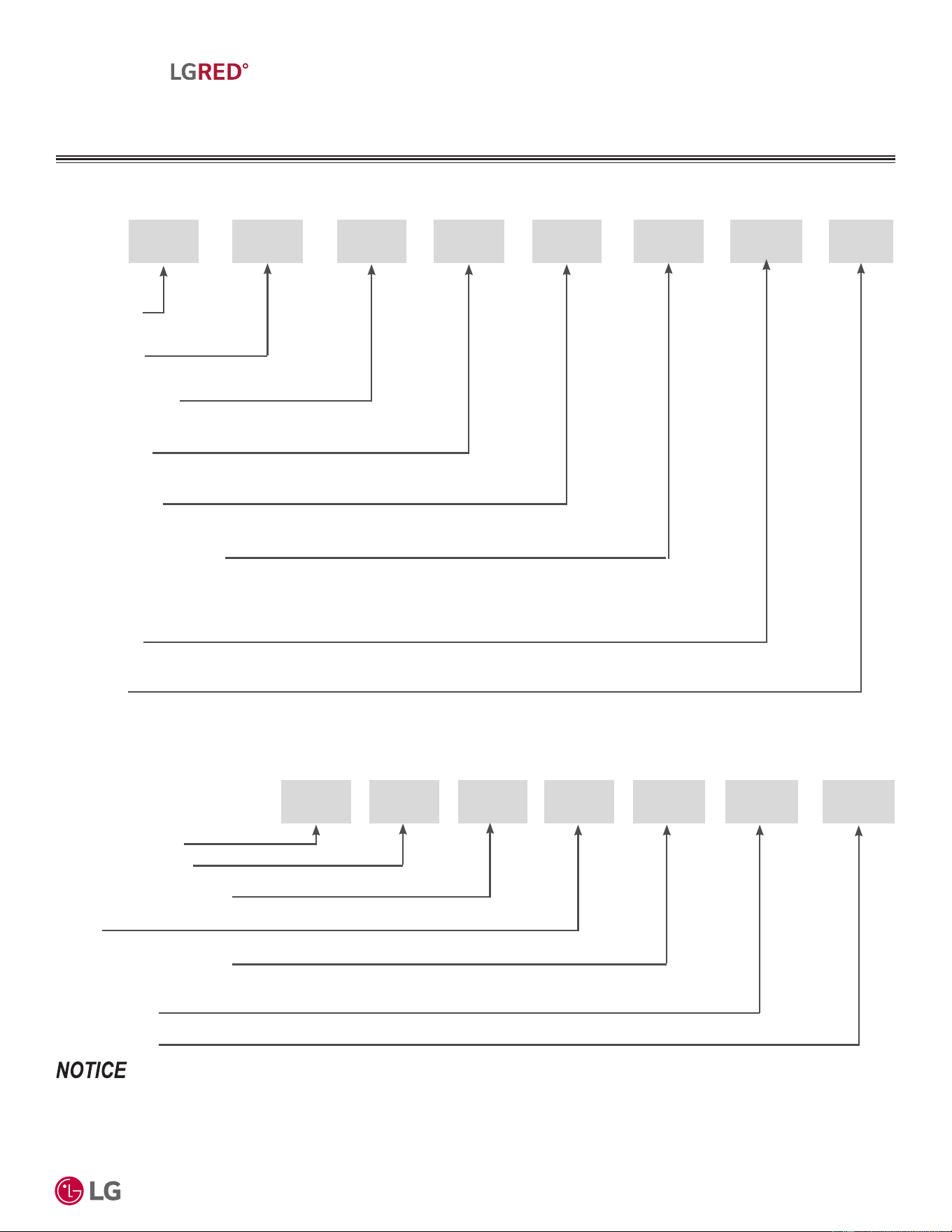
UNIT NOMENCLATURE
X A 30 1 A
1. Refrigerant
K = R32
7. Generation
1 to 9
18 = 18,000 Btu/h
24 = 24,000 Btu/h
30 = 30,000 Btu/h
36 = 36,000 Btu/h
42 = 42,000 Btu/h
48 = 48,000 Btu/h
U MK
2. Component
U = Outdoor Unit
3. Product Category
M = Multi
4. Product Type
X = Null
8. Function
A = 208~230V
6. Nominal Capacity (Btu/h)
Multi-Zone Systems — Outdoor Units
5. Product Grade
A = LGRED°
Branch Distribution Units
• 9ROWDJHIRUDOOHTXLSPHQWLV9+]SKDVH
• $OOLQGRRUXQLWVDUHFRPSDWLEOHZLWKZLUHGFRQWUROOHUV
• $OORXWGRRUXQLWVDUH/*$3FRQWUROQHWZRUNFRPSDWLEOH
• &RPSDWLEOH,'8QRPHQFODWXUHLVOLVWHGLQWKH0XOWL)0XOWL)0$;,QGRRU8QLW(QJLQHHULQJ0DQXDOV
M
BD 36
BD: Branch Distribution Unit
P = Part (Accessory)
P
Type: M = Multi-Zone
Family
Number of Port Connections
(Maximum Number of Connectable Indoor Units): 2, 3, 4
Generation: 0, 1
02 ZR
Refrigerant: R32
'XHWRRXUSROLF\RIFRQWLQXRXVSURGXFWLQQRYDWLRQVRPHVSHFL¿FDWLRQVPD\FKDQJHZLWKRXWQRWL¿FDWLRQ
©
/*(OHFWURQLFV86$,QF(QJOHZRRG&OLIIV1-$OOULJKWVUHVHUYHG³/*´LVDUHJLVWHUHGWUDGHPDUNRI/*&RUS
6
R32 Multi F and Multi F MAX with LGRED° Outdoor Unit Engineering Manual
MULTI
F
MAX
MULTI
F
WITH
LG AIR CONDITIONER
TECHNICAL SOLUTION (LATS)
LG Air Conditioner Technical Solution (LATS) Software
A properly designed and installed refrigerant piping system is critical
to the optimal performance of LG air-conditioning systems. To assist
engineers, LG offers, free of charge, LG Air Conditioner Technical
Solution (LATS) software—a total design solution for LG air condi-
tioning systems. Contact your LG Rep for the best software program
for your application.
7RUHGXFHWKHULVNRIGHVLJQLQJDQLPSURSHUDSSOLHGV\VWHPRURQHWKDW
ZLOOQRWRSHUDWHFRUUHFWO\/*UHTXLUHVWKDW/$76VRIWZDUHEHXVHGRQDOO
SURMHFWV
Formats
LATS is available to LG customers in two user interfaces: LATS HVAC and LATS Revit. Both LATS formats are available through
www.myLGHVAC.com, or contact an LG Sales Representative.
LATS HVAC is a Windows
®
-based application that aids engineers in designing LG Variable Refrigerant Flow (VRF), Multi F / Multi F MAX,
Single-Zone, DOAS, and Energy Recovery Ventilator (ERV) systems.
:LQGRZV
®
LVDUHJLVWHUHGPDUNRI0LFURVRIW
®
&RUSRUDWLRQ
LATS Revit integrates the LG LATS program with Revit
®
software**. It permits engineers to layout and validate LG VRF, Multi F / Multi F
MAX, Single-Zone, and DOAS directly into Revit drawings.
5HYLW
®
LVDUHJLVWHUHGPDUNRI$XWRGHVN,QF
Features
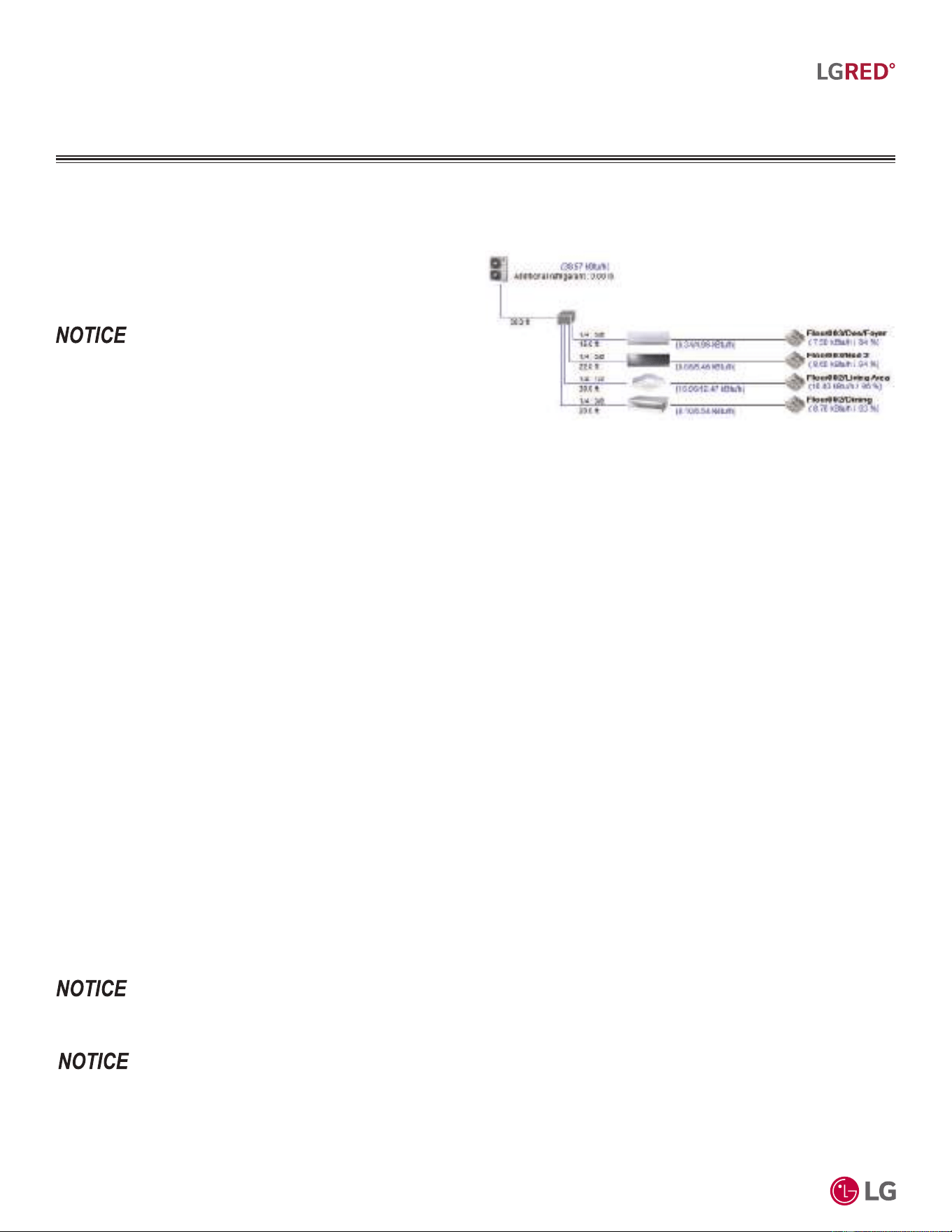
All LG product design criteria have been loaded into the program, making LATS simple to use: double click or drag and drop the component
choices. Build systems in Tree Mode where the refrigerant system can be viewed. Switch to a Schematic diagram to see the electrical and
communications wiring.
LATS software permits the user to input region data, indoor and outdoor design temperatures, modify humidity default values, zoning, specify
type and size of outdoor units and indoor units, and input air flow and external static pressure (ESP) for ducted indoor units.
The program can also:
• Import building loads from a separate Excel file.
• Present options for outdoor unit auto selection.
• Automatically calculate component capacity based on design
conditions for the chosen region.
• Verify if the height differences between the various system
components are within system limits.
• Provide the correct size of each refrigerant piping segment and LG
Y-Branches and Headers.
• Adjust overall piping system length when elbows are added.
• Check for component piping limitations and flag if any parameters
are broken.
• Factor operation and capacity for defrost operation.
• Calculate refrigerant charge, noting any additional trim charge.
• Suggest accessories for indoor units and outdoor units.
• Run system simulation.
)HDWXUHVGHSHQGRQZKLFK/$76SURJUDPLVEHLQJXVHGDQGWKHW\SHRIV\VWHPEHLQJGHVLJQHG&RQWDFW\RXU/*UHSUHVHQWDWLYHIRUWKHEHVWVRIW-
ZDUHSURJUDPIRU\RXUDSSOLFDWLRQ
$Q\¿HOGFKDQJHVVXFKDVUHURXWLQJVKRUWHQLQJRUOHQJWKHQLQJDSLSHVHJPHQWDGGLQJRUHOLPLQDWLQJHOERZVDQGRU¿WWLQJV
UHVL]LQJDGGLQJRUHOLPLQDWLQJLQGRRUXQLWVFKDQJLQJWKHPRXQWLQJKHLJKWRUPRYLQJWKHORFDWLRQRIDGHYLFHRU¿WWLQJGXU-
ing installation must be done with caution and ALWAYS VERIFIED in LATS SOFTWARE BEFORE supplies are purchased or
LQVWDOOHG'RLQJVRZLOOOHDGWRDPRUHSUR¿WDEOHLQVWDOODWLRQUHGXFHWKHSRWHQWLDOIRUUHZRUNDQGZLOOUHGXFHWKHSRWHQWLDOIRU
multiple visits to the job site to complete the system set up.
Figure 1: LATS Example (Tree Diagram; Illustrative Purposes Only.
System will Vary Depending On Modell).
'XHWRRXUSROLF\RIFRQWLQXRXVSURGXFWLQQRYDWLRQVRPHVSHFL¿FDWLRQVPD\FKDQJHZLWKRXWQRWL¿FDWLRQ
©
/*(OHFWURQLFV86$,QF(QJOHZRRG&OLIIV1-$OOULJKWVUHVHUYHG³/*´LVDUHJLVWHUHGWUDGHPDUNRI/*&RUS
7
R32 Multi F and Multi F MAX with LGRED° Outdoor Unit Engineering Manual
MULTI
F
MAX
MULTI
F
WITH
LG AIR CONDITIONER
TECHNICAL SOLUTION (LATS)
LATS Generates a Complete Project Report
LATS software also generates a report containing project design parameters, cooling and heating design data, system component perfor-
mance, and capacity data. The report includes system combination ratio and refrigerant charge calculations; and provides detailed bill of
material, including outdoor units, indoor units, control devices, accessories, refrigerant pipe sizes segregated by building, by system, by pipe
size, and by pipe segments. LATS can generate an Excel GERP report that can be imported into the LG SOPS pricing and ordering system.
Proper Design to Install Procedure
LG encourages a two report design-to-install-procedure. After the design engineer determines building / zone loads and other details, the
engineer opens the LATS program and inputs the project’s information. When the design is complete, the “Auto Piping” and “System Check”
functions must be used to verify piping sizes, limitations, and if any design errors are present. If errors are found, engineers must adjust the
design, and run Auto Piping and System Check again. When the design passes the checks, then the engineer prints out a project “Shop
Drawing” (LATS Tree Diagram) and provides it to the installing contractor. The contractor must follow the LATS Tree Diagram when building
the piping system, but oftentimes the design changes on the building site:
• Architect has changed location and/or purpose of room(s).
• Outdoor unit cannot be placed where originally intended.
• Structural elements prevent routing the piping as planned.
• Air conditioning system conflicts with other building systems (plumbing, gas lines, etc.).
The contractor must mark any deviation from the design on the Shop Drawing, including as-built straight lines and elbows. This “Mark Up”
drawing must be returned to the design engineer or Rep, who must input contractor changes into the LATS file. (Copy the original LATS soft-
ware file, save and rename as a separate file, and modify all piping lengths by double-clicking on each length and editing information.) Like
the shop drawing, the Auto Piping and System Check must also be run on this new “As Built” drawing. The design engineer or Rep must then
provide the final As Built file to the contractor. The Mark Up version must be compared to the As Built version for:
• Differences in pipe diameter(s). If incorrect diameters have been installed, the piping must be changed out. If pipe diameters have changed,
check if Y-Branches will also need to be changed.
• Changes to outdoor unit and indoor unit capacities. Capacities changes will impact line length changes.
• Additional refrigerant charge quantity (“Trim Charge”). Trim charge will change if piping lengths and diameters change. The As Built version
must reflect installed piping lengths to ensure correct trim charge.
All documents submitted by the contractor, as well as the Shop Drawing and the As Built Drawing files must be provided for commissioning
purposes. Model and serial numbers for all system components must also be submitted. If the steps previously detailed are not followed, and
all documents are not provided to the commissioning agent, the project runs the risk of not being commissioned and voiding any limited war-
ranty LG offers on the equipment.
$Q\¿HOGFKDQJHVVXFKDVUHURXWLQJVKRUWHQLQJRUOHQJWKHQLQJDSLSHVHJPHQWDGGLQJRUHOLPLQDWLQJHOERZVDQGRU¿WWLQJV
UHVL]LQJDGGLQJRUHOLPLQDWLQJLQGRRUXQLWVFKDQJLQJWKHPRXQWLQJKHLJKWRUPRYLQJWKHORFDWLRQRIDGHYLFHRU¿WWLQJGXU-
ing installation must be done with caution and ALWAYS VERIFIED in LATS SOFTWARE BEFORE supplies are purchased or
LQVWDOOHG'RLQJVRZLOOOHDGWRDPRUHSUR¿WDEOHLQVWDOODWLRQUHGXFHWKHSRWHQWLDOIRUUHZRUNDQGZLOOUHGXFHWKHSRWHQWLDOIRU
multiple visits to the job site to complete the system commissioning.

'XHWRRXUSROLF\RIFRQWLQXRXVSURGXFWLQQRYDWLRQVRPHVSHFL¿FDWLRQVPD\FKDQJHZLWKRXWQRWL¿FDWLRQ
©
/*(OHFWURQLFV86$,QF(QJOHZRRG&OLIIV1-$OOULJKWVUHVHUYHG³/*´LVDUHJLVWHUHGWUDGHPDUNRI/*&RUS
8
R32 Multi F and Multi F MAX with LGRED° Outdoor Unit Engineering Manual
MULTI
F
MAX
MULTI
F
WITH
To use the manual equipment selection procedure in choosing the multi-zone system that is the most appropriate for the space, as with
traditional air-conditioning systems, follow similar protocols outlined in Manual J from the Air Conditioning Contractors of America (ACCA; see
www.acca.org).
1. Obtain the design conditions, and calculate the maximum cool and heat loads for the structure.
2. Select the equipment (choosing the appropriate indoor units and outdoor unit):
• Determine number of zones.
• Determine total number of indoor units (refer to zone load calculations when choosing indoor units).
• Determine number of indoor units allocated to each outdoor unit, considering allowable indoor unit connections, both indoor unit and
outdoor unit capacities, and system piping capabilities.
3. Determine the corrected capacity for the indoor units and outdoor unit using LATS Multi F software (preferred method) or:
• System Combination Tables.
• Capacity Tables (it may be necessary to interpolate).
• Capacity Coefficient Factors (such as refrigerant line length derates, design condition derates, defrost operation derate [heating mode],
altitude derate [if applicable]).
4. Compare corrected capacities to load calculations.
5. Reselect equipment if necessary.
2EWDLQ'HVLJQ&RQGLWLRQV&DOFXODWH0D[LPXP&RRO+HDW/RDGV
Obtain the winter outdoor / indoor temperature and summer and winter outdoor / indoor temperature design parameters for the location in
which the system is installed. Determine if summer or winter design gains, relative humidity, and building features like skylights, orientation,
number of occupants, etc., would change the total heat loss / gain and sensible / latent heat gain, and then calculate the maximum cool and
heat loads for the space (using Manual J or energy modeling programs).
Select the Equipment
Determine the Number of Zones
Multi F heat pump systems can cool or heat, but not simultaneously. When designing larger-capacity Multi F with LGRED heat pump systems
or a Multi F MAX LGRED system, the designer may be able to combine spaces with similar load profiles located near or adjacent to each
other into “thermal zones.” After combining like spaces into zones that will be served by a single (or grouped) indoor unit(s), calculate the
peak cooling and heating loads for each zone.
Choosing the Appropriate Indoor Units
Determine the appropriate indoor unit capacity that satisfies the given zone load calculations, and choose how many (and which styles of)
indoor units will be required. See Table 1 on page 9 for allowable indoor unit to outdoor unit connections, and the maximum number of con-
nectable indoor units on each Multi F and Multi F MAX outdoor unit. When choosing indoor units, also consider the cooling and heating CFM,
featured airflow specifications, and static pressure (if applicable) for each indoor unit.
Avoid oversizing indoor units in an attempt to increase the air exchange rate in the space. Multi F and Multi F MAX systems are designed for
minimum airflow over the coil to maximize latent capacity while cooling, maintain a comfortable, consistent discharge air temperature while
heating, and minimize fan motor power consumption. In extreme cases, oversizing the indoor units may affect outdoor unit size selection and
compromise the outdoor unit’s ability to effectively match the space load(s).
For proper system operation:
1. At least two indoor units must be connected to the outdoor unit.
2. Total connected indoor unit nominal capacity must be at least the minimum connection capacity index specified for the outdoor unit (see
Table 2 on page 10), and not exceed the maximum connection capacity index specified for the outdoor unit (see Table 2 on page 10).
3. To calculate the connected total indoor unit nominal capacity, simply sum up the nominal capacities of all indoor units.
• For mid static duct, high static duct, and vertical-horizontal air handling indoor units, a 1.3 multiplier must first be applied before adding
to the sum of other indoor units (when connected to an outdoor unit other than the KUMXA361A, KUMXA421A, and KUMXA481A).
• When mid static duct, high static duct, and / or vertical-horizontal air handling indoor units are the only connected indoor units, the
multiplier is 1.2.
MANUAL EQUIPMENT
SELECTION PROCEDURE
9DULRXVWRROVDUHDYDLODEOHWRDVVLVWLQSURSHUO\GHVLJQLQJ/*5VSOLWV\VWHPV5HIHUWRWKH³5$SSOLFDWLRQ*XLGH´WKH³6LPSOH&DOFXODWRUIRU&D-
SDFLW\5HIULJHUDQW&KDUJHDQG(63´WKH³/*$LU&RQGLWLRQHU7HFKQLFDO6ROXWLRQV´/$76VRIWZDUHSURJUDPDQGWKHORFDO/*6DOHV5HSUHVHQWDWLYH
'XHWRRXUSROLF\RIFRQWLQXRXVSURGXFWLQQRYDWLRQVRPHVSHFL¿FDWLRQVPD\FKDQJHZLWKRXWQRWL¿FDWLRQ
©
/*(OHFWURQLFV86$,QF(QJOHZRRG&OLIIV1-$OOULJKWVUHVHUYHG³/*´LVDUHJLVWHUHGWUDGHPDUNRI/*&RUS
9
R32 Multi F and Multi F MAX with LGRED° Outdoor Unit Engineering Manual
MULTI
F
MAX
MULTI
F
WITH
)RUDOORFDWHGFDSDFLW\LQIRUPDWLRQVHHWKHFRPELQDWLRQWDEOHVLQWKH0XOWL)0XOWL)0$;ZLWK/*5('&RPELQDWLRQ'DWD0DQXDORQZZZOJKYDF
FRP)RUSHUIRUPDQFHGDWDVHH0XOWL)0XOWL)0$;ZLWK/*5('3HUIRUPDQFH'DWD0DQXDORQZZZOJKYDFFRP
9DULRXVWRROVDUHDYDLODEOHWRDVVLVWLQSURSHUO\GHVLJQLQJ/*5VSOLWV\VWHPV5HIHUWRWKH³5$SSOLFDWLRQ*XLGH´WKH³6LPSOH&DOFXODWRUIRU&D-
SDFLW\5HIULJHUDQW&KDUJHDQG(63´WKH³/*$LU&RQGLWLRQHU7HFKQLFDO6ROXWLRQV´/$76VRIWZDUHSURJUDPDQGWKHORFDO/*6DOHV5HSUHVHQWDWLYH
Choosing the Appropriate Indoor Units, Continued.
Indoor Units Outdoor Units
Model Type
IDU Nominal
Capacity (Btu/h)
KUMXA181A KUMXA241A KUMXA301A KUMXA361A KUMXA421A KUMXA481A
Maximum No. of Connectable Indoor Units
234568
ART COOL Mirror
9,000 OOOOOO
12,000 OOOOOO
18,000 - OOOOO
Standard Wall Mounted
7,000 OOOOOO
9,000 OOOOOO
12,000 OOOOOO
15,000 OOOOOO
18,000 - OOOOO
24,000 - OOOOO
Ceiling Concealed Duct-
Low Static
9,000 OOOOOO
12,000 OOOOOO
18,000 - OOOOO
Convertible
Mid Static Duct
9,000 OOOOOO
12,000 OOOOOO
18,000 - OOOOO
24,000 - - O O O O
Ceiling Concealed
Mid Static Duct
30,000 - - - O O O
36,000 - - - O O O
Four-Way Ceiling Cassette
7,000 OOOOOO
9,000 OOOOOO
12,000 OOOOOO
18,000 - OOOOO
Low-Wall Console
9,000 OOOOOO
12,000 OOOOOO
15,000 OOOOOO
Vertical-Horizontal Air Handler
12,000 OOOOOO
18,000 - OOOOO
24,000 - - O O O O
30,000 - - - O O O
36,000 - - - O O O
Table 1: Allowable Indoor Unit to Outdoor Unit Connections.
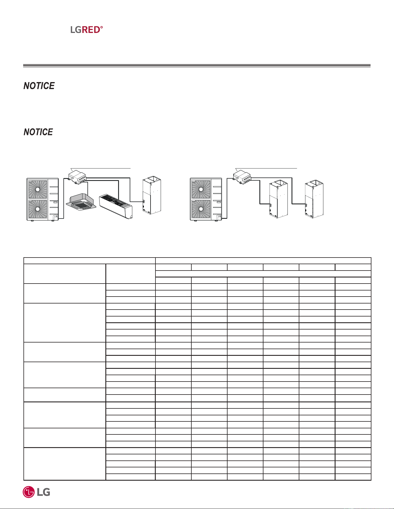
Examples
Branch Distribution Unit (PMBD3620ZR)
+
18 18 + Total Capacity Index = = 36 < 56
Branch Distribution Unit (PMBD3620ZR)
First Indoor Unit:
KNUDB121A
+ + Outdoor Unit: KUMXA421A
12 9 18 + + Total Capacity Index = = 39 < 56
Acceptable
Combination
Second Indoor Unit:
KNUAB091A
Third Indoor Unit:
KNMLB181A
Outdoor Unit: KUMXA421A
First Indoor Unit:
KNMLB181A
Second Indoor Unit:
KNMLB181A
Acceptable
Combination
Example 1
Example 2
MANUAL EQUIPMENT
SELECTION PROCEDURE
'XHWRRXUSROLF\RIFRQWLQXRXVSURGXFWLQQRYDWLRQVRPHVSHFL¿FDWLRQVPD\FKDQJHZLWKRXWQRWL¿FDWLRQ
©
/*(OHFWURQLFV86$,QF(QJOHZRRG&OLIIV1-$OOULJKWVUHVHUYHG³/*´LVDUHJLVWHUHGWUDGHPDUNRI/*&RUS
10
R32 Multi F and Multi F MAX with LGRED° Outdoor Unit Engineering Manual
MULTI
F
MAX
MULTI
F
WITH
Choosing the Appropriate Outdoor Unit
After all indoor units are properly sized to offset the applicable loads in each zone, select the outdoor unit by choosing a size that meets
both the load-cooling requirement, and offsets the sum of the heating load. Then, the system’s combination ratio should be evaluated and
confirmed it is within the allowable range (the combination ratio compares the nominal capacity of all connected indoor units to the nominal
capacity of the outdoor unit serving them). The total nominal capacity of all indoor units should be smaller than the total nominal capacity of
the outdoor unit. If the combination ratio is more than 100%, the designer is undersizing the outdoor unit relative to the combined nominal
capacity of the connected indoor units. In some designs, oversized indoor units may be unavoidable in the case where the smallest size
indoor unit available from LG is larger than what is necessary to satisfy the zone load. This scenario may also occur when an indoor unit
selection one size down from the selected unit is slightly short of fulfilling the design load requirements, and the designer must choose the
next largest size unit. Sometimes it is recommended to choose a larger capacity outdoor unit if the installation space is big enough. Also,
it may be prudent to oversize the outdoor unit to address those times when the weather conditions may exceed the design conditions, to
minimize the possibility of ventilation systems that causes the space temperature to drift outside design parameters, or when the indoor unit’s
entering air temperature falls outside the approved design temperature range.
9DULRXVWRROVDUHDYDLODEOHWRDVVLVWLQSURSHUO\GHVLJQLQJ/*5VSOLWV\VWHPV5HIHUWRWKH³5$SSOLFDWLRQ*XLGH´WKH³6LPSOH&DOFXODWRUIRU&D-
SDFLW\5HIULJHUDQW&KDUJHDQG(63´WKH³/*$LU&RQGLWLRQHU7HFKQLFDO6ROXWLRQV´/$76VRIWZDUHSURJUDPDQGWKHORFDO/*6DOHV5HSUHVHQWDWLYH
Choosing the Appropriate Indoor Units, Continued.
MANUAL EQUIPMENT
SELECTION PROCEDURE
Determine the Corrected Capacity
The corrected cooling / heating capacity is different from the rated cooling / heating capacity. The corrected capacity includes changes in
unit performance after considering design temperatures, available capacity that can be allocated from the outdoor unit, pressure drop due
to refrigerant line length, defrost operation in heating mode, and (if applicable) altitude. Depending on the location of the building, additional
capacity correction factors may need to be applied.
Using the Outdoor Unit Cooling and Heating Capacity Tables
Rated cooling capacity ratings are obtained with air entering the indoor unit at 80ºF dry bulb (DB) and 67ºF wet bulb (WB), and outdoor ambi-
ent conditions of 95ºF dry bulb (DB) and 75ºF wet bulb (WB). Rated heating capacity ratings are obtained with air entering the indoor unit at
70ºF dry bulb (DB) and 60ºF wet bulb (WB) and outdoor ambient conditions of 47ºF dry bulb (DB) and 43ºF wet bulb (WB).
To evaluate the total outdoor unit capacity at design conditions, using LATS software (preferred method) or reference the Performance Data
Capacity Tables in the Multi F / Multi F MAX with LGRED Performance Data Manual on www.lghvac.com. All design temperatures are not
explicitly shown in the charts, therefore, interpolation may be necessary to calculate the capacity for specific design conditions. Based on the
premise that capacity follows a linear curve, the following formula can be applied:
(y - y1) / (y2 - y1) = (x - x1) / (x2 - x1)
Where
y = Missing Capacity (Capacity at the Design Temperature).
1
y1 = Capacity at Lower Temperature (Smaller value of the two nearest published TC datapoints).
y2 = Capacity at Higher Temperature (Higher value of the two nearest published TC datapoints).
x = Design Temperature (Temperature not shown in published capacity tables).
2
x1 = (Smaller value of the two nearest published temperature datapoints).
x2 = (Larger value of the two nearest published temperature datapoints).
1
0HGLDQEHWZHHQWZRSXEOLVKHG7RWDO&DSDFLW\>7&@%WXKGDWDSRLQWVLQWKHFDSDFLW\WDEOH
2
0HGLDQEHWZHHQWZRQHDUHVWSXEOLVKHGWHPSHUDWXUHGDWDSRLQWV
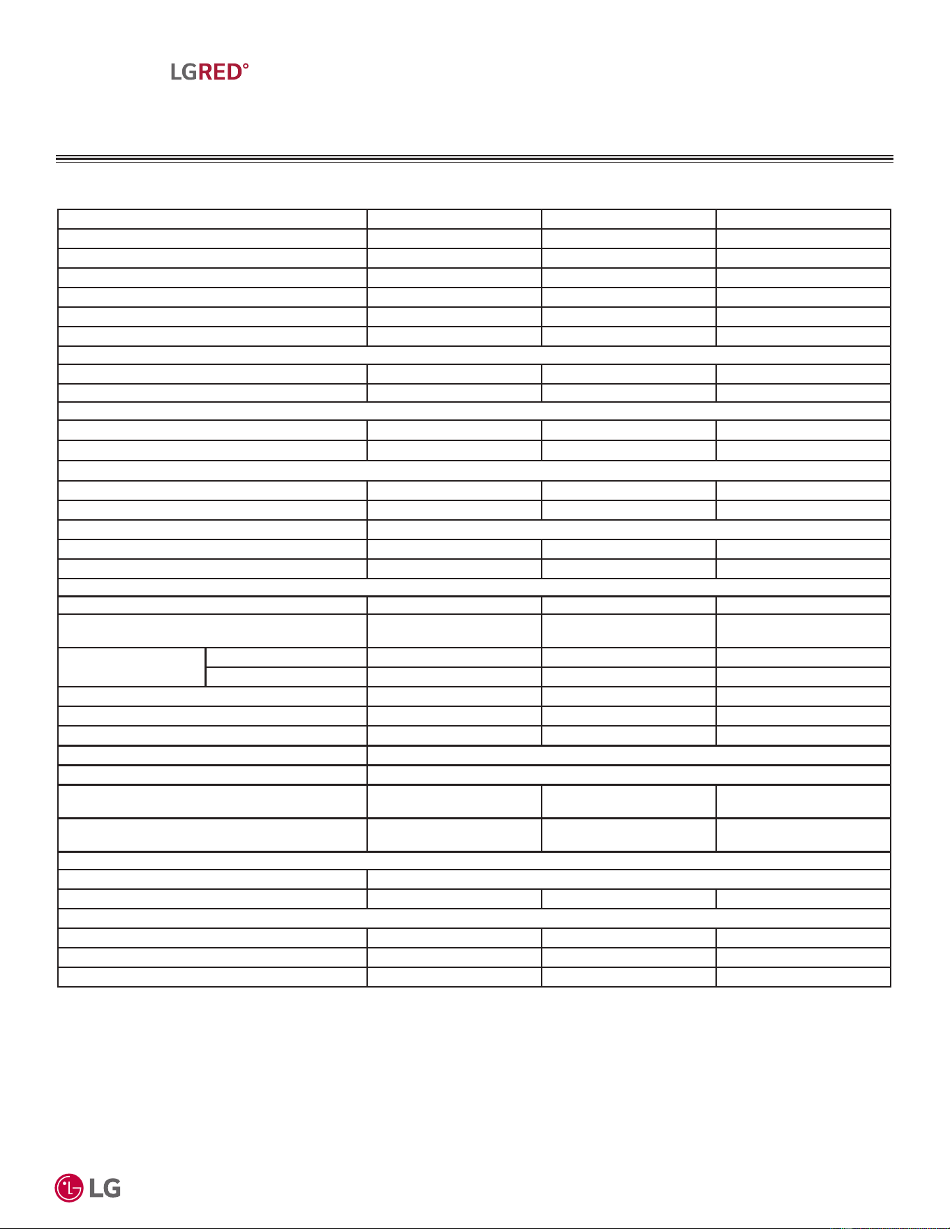
Outdoor Units
KUMXA181A KUMXA241A KUMXA301A KUMXA361A KUMXA421A KUMXA481A
Rated Capacity (Btu/h)*
Cooling 18,000 24,000 28,400 36,000 42,000 48,000
Heating 22,000 26,000 30,000 45,000 48,000 52,500
Connectable Indoor
Units
Min. No. of IDUs 222222
Max. No. of IDUs234568
Min. Capacity Index 14,000 14,000 14,000 18,000 18,000 18,000
Max. Capacity Index 24,000 33,000 40,000 48,000 56,000 65,000
Table 2: Rated Outdoor Unit Capacity.
5DWHGFDSDFLW\VKRZQLVEDVHGRQDQRQGXFWHGLQGRRUXQLWFRPELQDWLRQ5HIHUWRFRPELQDWLRQWDEOHVIRUUDWHGFDSDFLW\RIRWKHUFRPELQDWLRQV
'XHWRRXUSROLF\RIFRQWLQXRXVSURGXFWLQQRYDWLRQVRPHVSHFL¿FDWLRQVPD\FKDQJHZLWKRXWQRWL¿FDWLRQ
©
/*(OHFWURQLFV86$,QF(QJOHZRRG&OLIIV1-$OOULJKWVUHVHUYHG³/*´LVDUHJLVWHUHGWUDGHPDUNRI/*&RUS
11
R32 Multi F and Multi F MAX with LGRED° Outdoor Unit Engineering Manual
MULTI
F
MAX
MULTI
F
WITH
Using the Indoor Unit Cooling and Heating Capacity Tables
The datapoints shown in the indoor unit cooling and heating capacity charts are based on (and convey) an indoor unit operating with maxi-
mum possible refrigerant flow from the outdoor unit and before any derates are applied. In other words, the capacities displayed reflect what
the indoor unit would produce if it was the only indoor unit that required capacity, and the outdoor unit did not have to allocate any capacity to
another indoor unit.
System operation with a combination of indoor units is not conveyed in these charts, however, the information can be used to calculate
indoor unit allocated capacity (without using the system combination tables). Simply calculate by using the formula:
Where
Qidu(combi) = Qodu(rated) x Qidu(rated)
ȉ4LGXUDWHG
• 7KHIRUPXODFDQEHXVHGWRILQGLQGLYLGXDOLQGRRUXQLWFDSDFLW\IRU0XOWL)0$;ZLWK/*5('V\VWHPV
• $PRUHDFFXUDWHPHWKRGWRGHWHUPLQHH[SHFWHGFDSDFLW\ZRXOGEHWRDSSO\WKHRXWGRRUXQLW¶VFRUUHFWHGFDSDFLW\LQVWHDGRIUDWHGFDSDFLW\
Qidu(combi) = Individual Indoor Unit Combination Capacity.
Qodu(rated) = Outdoor Unit Rated Capacity.
Qidu(rated) = Individual Indoor Unit Rated Capacity.
Ȉ4LGXUDWHG 7RWDO&RQQHFWHG,QGRRU8QLW5DWHG&DSDFLW\
MANUAL EQUIPMENT
SELECTION PROCEDURE
9DULRXVWRROVDUHDYDLODEOHWRDVVLVWLQSURSHUO\GHVLJQLQJ/*5VSOLWV\VWHPV5HIHUWRWKH³5$SSOLFDWLRQ*XLGH´WKH³6LPSOH&DOFXODWRUIRU&D-
SDFLW\5HIULJHUDQW&KDUJHDQG(63´WKH³/*$LU&RQGLWLRQHU7HFKQLFDO6ROXWLRQV´/$76VRIWZDUHSURJUDPDQGWKHORFDO/*6DOHV5HSUHVHQWDWLYH
Qidu(combi) = Qodu(rated) x Qidu(rated)
ȉ4LGXUDWHG
Using the System Combination Tables
0XOWL)V\VWHPFRPELQDWLRQWDEOHVLOOXVWUDWHKRZHDFKLQGRRUXQLWUHFHLYHVDSHUFHQWDJHRIWRWDORXWGRRUXQLWUDWHGFDSDFLW\$OORFDWLRQLVEDVHGRQ
• Combinations of Non-Ducted Indoor Units
• Combinations of Ducted Indoor Units
• Combinations of Mixed Non-Ducted and Ducted Indoor Units
0XOWL)0$;ZLWK/*5('V\VWHPFRPELQDWLRQWDEOHVRQO\VKRZWKHWRWDOFRQQHFWHGLQGRRUXQLWFDSDFLW\EXWLQGLYLGXDOLQGRRUXQLWFDSDFLW\FDQEH
FDOFXODWHGXVLQJWKHIRUPXOD
• $PRUHDFFXUDWHPHWKRGWRGHWHUPLQHH[SHFWHGFDSDFLW\ZRXOGEHWRDSSO\WKHRXWGRRUXQLW¶VFRUUHFWHGFDSDFLW\LQVWHDGRIUDWHGFDSDFLW\
• )RUDOORFDWHGFDSDFLW\LQIRUPDWLRQVHHWKHFRPELQDWLRQWDEOHVLQWKH³0XOWL)0XOWL)0$;/*5('&RPELQDWLRQ'DWD0DQXDO´
RQZZZOJKYDFFRP)RUSHUIRUPDQFHGDWDVHH³0XOWL)0XOWL)0$;ZLWK/*5('3HUIRUPDQFH'DWD0DQXDO´RQZZZOJKYDFFRP
'XHWRRXUSROLF\RIFRQWLQXRXVSURGXFWLQQRYDWLRQVRPHVSHFL¿FDWLRQVPD\FKDQJHZLWKRXWQRWL¿FDWLRQ
©
/*(OHFWURQLFV86$,QF(QJOHZRRG&OLIIV1-$OOULJKWVUHVHUYHG³/*´LVDUHJLVWHUHGWUDGHPDUNRI/*&RUS
12
R32 Multi F and Multi F MAX with LGRED° Outdoor Unit Engineering Manual
MULTI
F
MAX
MULTI
F
WITH
MANUAL EQUIPMENT
SELECTION PROCEDURE
9DULRXVWRROVDUHDYDLODEOHWRDVVLVWLQSURSHUO\GHVLJQLQJ/*5VSOLWV\VWHPV5HIHUWRWKH³5$SSOLFDWLRQ*XLGH´WKH³6LPSOH&DOFXODWRUIRU&D-
SDFLW\5HIULJHUDQW&KDUJHDQG(63´WKH³/*$LU&RQGLWLRQHU7HFKQLFDO6ROXWLRQV´/$76VRIWZDUHSURJUDPDQGWKHORFDO/*6DOHV5HSUHVHQWDWLYH
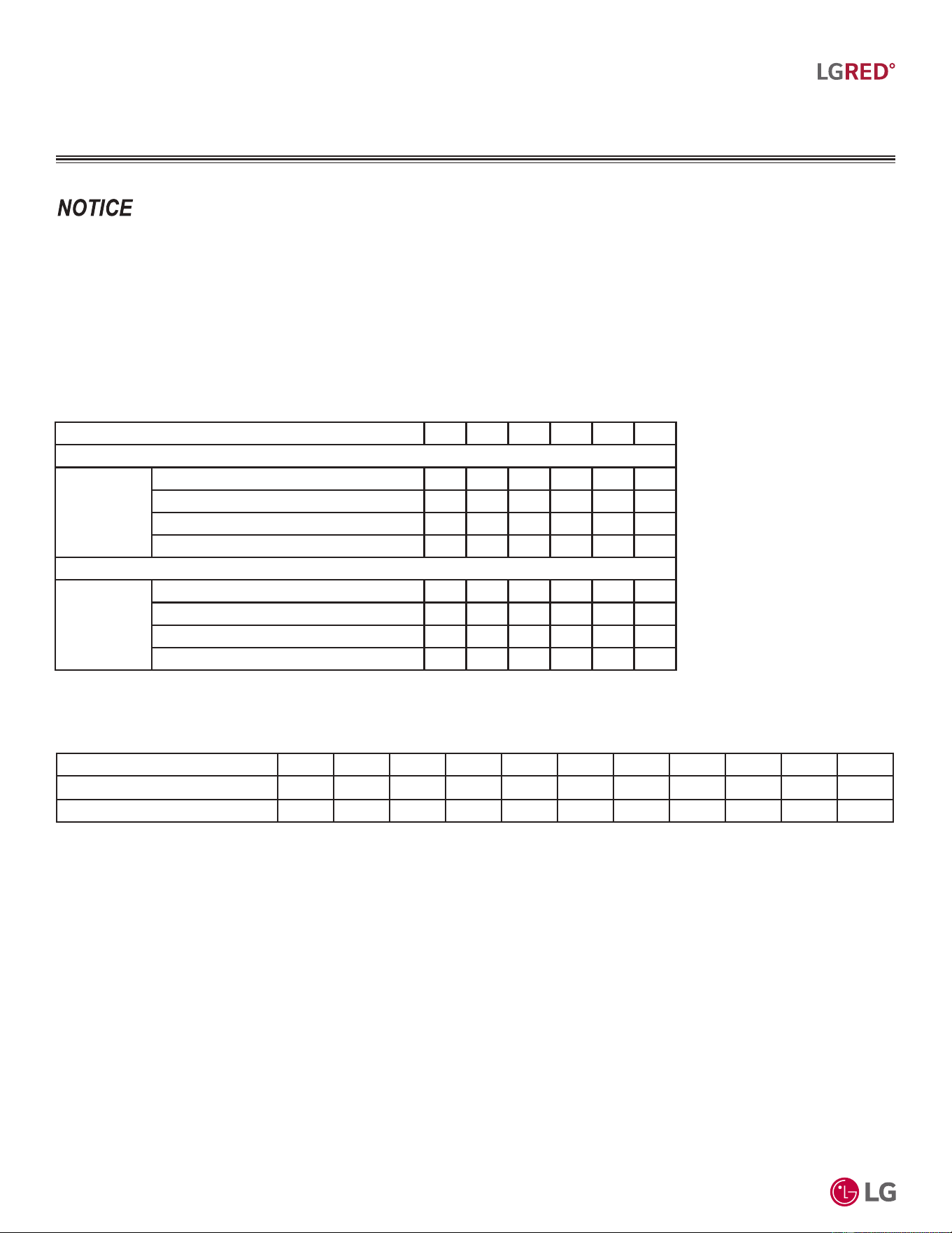
Table 3: Multi F with LGRED Outdoor Unit (Multiple Piping) to Indoor Unit Refrigerant Line Length Derate.
Capacity Coefficient Factors
Refrigerant Line Length Derates
For air-cooled systems, a capacity correction factor may have to be applied to account for the length of the system’s refrigerant pipe. Rate of
change in capacity due to increased piping lengths is shown in the table below, and in the tables on the next page.
Piping Length (ft.) 16.4 24.6 32.8 49.2 65.6 82.0
&RROLQJ&DSDFLW\&RHIILFLHQW)DFWRU
Rate of
Capacity
Change (%)
KUMXB181A (18,000 Btu/h) 100 100 98.2 95.4 92.4 89.6
KUMXB241A (24,000 Btu/h) 100 100 98.2 95.4 92.4 89.6
KUMXB301A (30,000 Btu/h) 100 100 98.2 95.4 92.4 89.6
KUMXB361A (36,000 Btu/h) 100 100 98.2 95.4 92.4 89.6
+HDWLQJ&DSDFLW\&RHIILFLHQW)DFWRU
Rate of
Capacity
Change (%)
KUMXB181A (18,000 Btu/h) 100 100 99.2 98.0 96.6 95.4
KUMXB241A (24,000 Btu/h) 100 100 99.2 98.0 96.6 95.4
KUMXB301A (30,000 Btu/h) 100 100 99.2 98.0 96.6 95.4
KUMXB361A (36,000 Btu/h) 100 100 99.2 98.0 96.6 95.4
Table 4: Multi F MAX with LGRED Outdoor Unit to Branch Distribution Unit Refrigerant Line Length Derates.
Main Piping Length (feet) 16.4 32.8 49.2 65.6 82.0 98.4 114.8 131.2 147.6 164.0 180.4
Cooling Capacity (%) 100.0 98.8 97.3 95.8 94.3 92.8 91.3 89.8 88.3 86.8 85.3
Heating Capacity (%) 100.0 99.6 99.2 98.7 98.3 97.8 97.4 96.9 96.5 96.0 95.6
'XHWRRXUSROLF\RIFRQWLQXRXVSURGXFWLQQRYDWLRQVRPHVSHFL¿FDWLRQVPD\FKDQJHZLWKRXWQRWL¿FDWLRQ
©
/*(OHFWURQLFV86$,QF(QJOHZRRG&OLIIV1-$OOULJKWVUHVHUYHG³/*´LVDUHJLVWHUHGWUDGHPDUNRI/*&RUS
13
R32 Multi F and Multi F MAX with LGRED° Outdoor Unit Engineering Manual
MULTI
F
MAX
MULTI
F
WITH
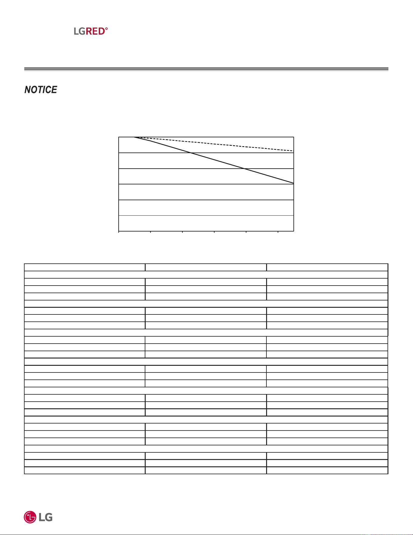
0 32.8 65.6 98.4 131.2 164.0 180.4
Main piping length (ft.)
70.0
75.0
80.0
85.0
90.0
95.0
100.0
Capacity (%)
Heating
capacity
Cooling
capacity
Figure 2: Multi F MAX with LGRED Outdoor Unit to Branch Distribution Unit Refrigerant Line Length Derate Chart.
MANUAL EQUIPMENT
SELECTION PROCEDURE
9DULRXVWRROVDUHDYDLODEOHWRDVVLVWLQSURSHUO\GHVLJQLQJ/*5VSOLWV\VWHPV5HIHUWRWKH³5$SSOLFDWLRQ*XLGH´WKH³6LPSOH&DOFXODWRUIRU&D-
SDFLW\5HIULJHUDQW&KDUJHDQG(63´WKH³/*$LU&RQGLWLRQHU7HFKQLFDO6ROXWLRQV´/$76VRIWZDUHSURJUDPDQGWKHORFDO/*6DOHV5HSUHVHQWDWLYH
Refrigerant Line Length Derates, Continued.
Piping Length (feet) Cooling Capacity (%) Heating Capacity (%)
%WXK,QGRRU8QLW0RGHOV
16.4 100.0 100.0
32.8 98.0 99.5
49.2 96.0 98.9
%WXK,QGRRU8QLW0RGHOV
16.4 100.0 100.0
32.8 97.5 98.8
49.2 95.0 97.5
%WXK,QGRRU8QLW0RGHOV
16.4 100.0 100.0
32.8 97.0 98.3
49.2 94.0 96.5
%WXK,QGRRU8QLW0RGHOV
16.4 100.0 100.0
32.8 97.2 98.2
49.2 93.0 95.4
%WXK,QGRRU8QLW0RGHOV
16.4 100.0 100.0
32.8 98.3 99.5
49.2 96.5 99.0
%WXK,QGRRU8QLW0RGHOV
16.4 100.0 100.0
32.8 97.8 99.2
49.2 95.5 98.4
%WXK,QGRRU8QLW0RGHOV
16.4 100.0 100.0
32.8 97.9 98.8
49.2 95.7 97.6
Table 5: Multi F MAX with LGRED Branch Distribution Unit to Indoor Unit Refrigerant Line Length Derates.
Altitude Correction Factor
The impact of air density must be considered on systems installed at a significant altitude above sea level, therefore, locally accepted
altitude correction factors must be applied.
'XHWRRXUSROLF\RIFRQWLQXRXVSURGXFWLQQRYDWLRQVRPHVSHFL¿FDWLRQVPD\FKDQJHZLWKRXWQRWL¿FDWLRQ
©
/*(OHFWURQLFV86$,QF(QJOHZRRG&OLIIV1-$OOULJKWVUHVHUYHG³/*´LVDUHJLVWHUHGWUDGHPDUNRI/*&RUS
14
R32 Multi F and Multi F MAX with LGRED° Outdoor Unit Engineering Manual
MULTI
F
MAX
MULTI
F
WITH
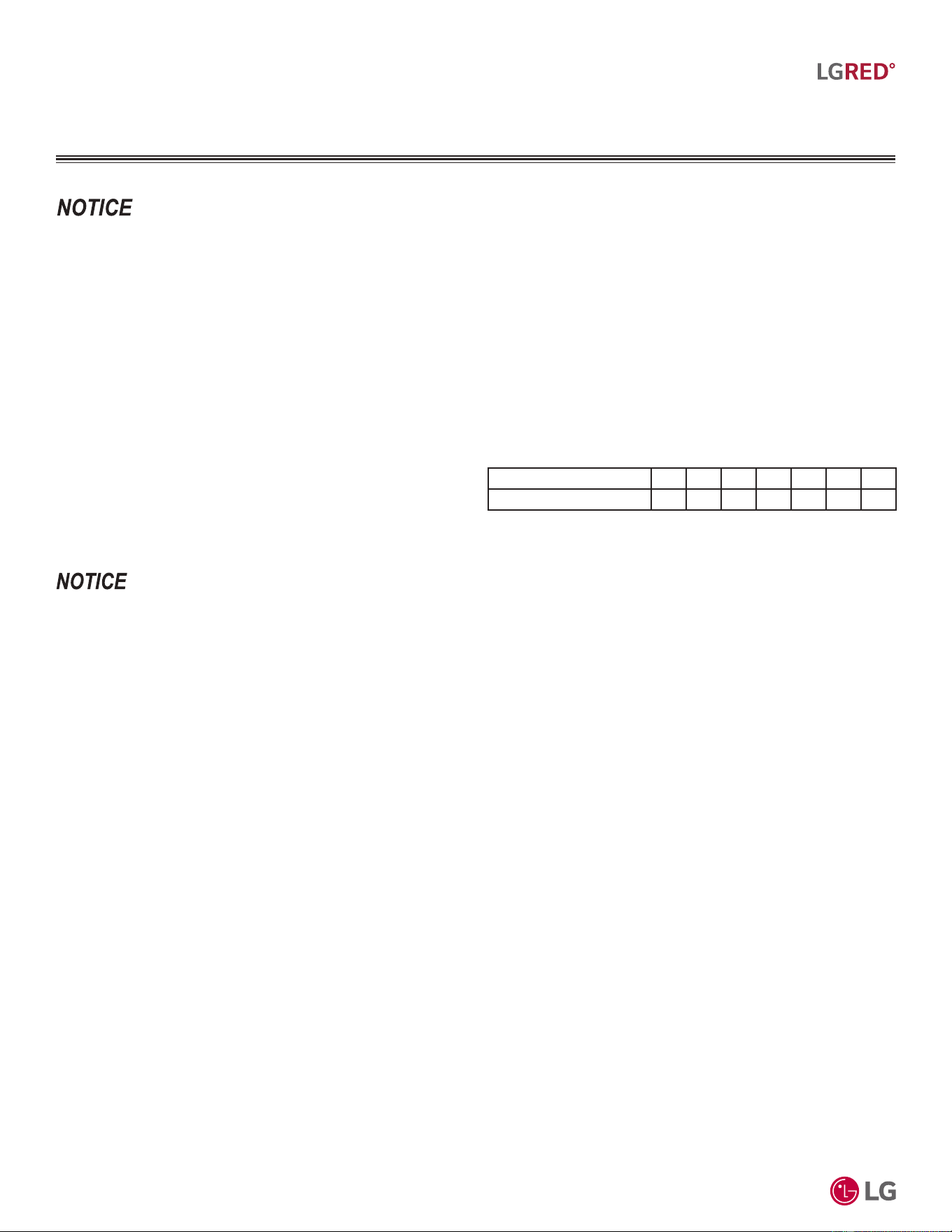
Table 6: Outdoor Unit Frost Accumulation Factor (Heating).
1
7KHUHZLOOEHDWHPSRUDU\UHGXFWLRQLQFDSDFLW\ZKHQIURVWLFHDFFXPXODWHVRQWKHRXWVLGHVXUIDFHRIWKHRXWGRRUXQLWKHDWH[FKDQJHU7KHOHYHORI
FDSDFLW\UHGXFWLRQGHSHQGVRQDQXPEHURIIDFWRUVIRUH[DPSOHRXWGRRUWHPSHUDWXUH)'%UHODWLYHKXPLGLW\5+DQGWKHDPRXQWRIIURVWSUHVHQW
Entering DB (ºF) 19.4 23.0 26.6 32.0 37.4 41.0 44.6
Derate factor 0.98 0.95 0.93 0.86 0.93 0.96 1.0
1
At 85% outdoor air relative humidity.
The frost accumulation factor does not account for effects of snow accumulation restricting airflow
through the outdoor unit coil.
Defrost Correction Factor for Heating Operation
The outdoor unit heating capacity may need to be adjusted for frost accumulation on air-cooled systems. If design day conditions are below
the dewpoint of the surrounding air, frost may not be a problem and no correction factor is needed. In certain weather conditions, however,
frost may form and accumulate on the air-cooled outdoor unit coil and impact the coils ability to transfer heat. If significant frost accumulates
on the outdoor unit coil, a defrost algorithm will start automatically. The timing between defrost periods is determined by the system’s ability
to achieve a target head pressure value.
Capacity and AHRI ratings tables do not factor in capacity reduction when frost has accumulated on the condenser coil, nor during defrost
operation.
Integrated heating capacity values can be obtained using the formula:
A = B x C
Where:
A = Integrated Heating Capacity.
B = Value found in the Capacity Table.
C = Correction Factor for Frost Accumulation Factor (see right).
&KHFNWKH,QGRRUDQG2XWGRRU8QLW6HOHFWLRQV
Compare the corrected cooling and heating capacities to the load calculations. Is each capacity sufficient for the zone it serves?
For each indoor unit, the corrected capacity must be at least equal to the total of the cooling design load (plus ventilation load, if applicable)
for the space(s) served by the indoor unit. For each indoor unit, the corrected capacity also must be at least equal to the total of the heating
design load (plus ventilation load, if applicable) for the space(s) and / or thermal zones served by the indoor unit.
The outdoor unit selected must be within the minimum and maximum indoor unit connection capacity index, and be large enough to offset
the total cooling load for all spaces it serves (account for ventilation air cooling load if the ventilation air has not been pretreated to room
neutral conditions). The outdoor unit must also be large enough to offset the total heating load for all spaces it serves.
If the corrected heating capacity ratio exceeds 100%, reselect the equipment, or change the system design by moving some of the load to
another system.
• Understand the design safety factors.
• Reference load calculations for actual cooling and heating capaci-
ties (applies in 99% of applications – consider total load when
latent load is greater than 30%).
• Verify that the sensible load of the zone is satisfied.
• Use caution when sizing to meet listed capacity specifications for
the scheduled manufacturer’s equipment.
• If further system design assistance is needed, or you have a
unique application you would like to discuss, contact your LG sales
rep.
1. Outdoor Unit Rated Capacity.
Q
odu(rated)
(From capacity tables).
2. Outdoor Unit Capacity at Ti, To Temperature.
Q
odu(Ti, To)
(From capacity tables).
3. Outdoor Unit Capacity Coefficient Factor.
F
(Ti, To)
= Q
odu(Ti, To)
/ Q
odu(rated)
4. Piping Correction Factor (From Capacity Coefficient
Factor Tables).
F
(length)
for each piping length
5. Individual Indoor Unit Combination Capacity.
Q
idu (combi)
= Q
odu(rated)
x Q
idu(rated)
/ Q
idu(rated-total)
6. Individual Indoor Unit Actual Capacity.
Q
idu (actual)
= Q
odu(combi)
x F
(Ti, To)
x F
(length, altitude)
6\VWHP6L]LQJ&KHFN)RUPXODV
Conclusions and Recommendations
MANUAL EQUIPMENT
SELECTION PROCEDURE
9DULRXVWRROVDUHDYDLODEOHWRDVVLVWLQSURSHUO\GHVLJQLQJ/*5VSOLWV\VWHPV5HIHUWRWKH³5$SSOLFDWLRQ*XLGH´WKH³6LPSOH&DOFXODWRUIRU&D-
SDFLW\5HIULJHUDQW&KDUJHDQG(63´WKH³/*$LU&RQGLWLRQHU7HFKQLFDO6ROXWLRQV´/$76VRIWZDUHSURJUDPDQGWKHORFDO/*6DOHV5HSUHVHQWDWLYH

MULTI F WITH LGRED°
OUTDOOR UNIT
PRODUCT DATA
Mechanical Specifications on page 16
General Data on page 17
Electrical Data on page 20
Functions, Controls, Options, and Accessories on page 21
Dimensions on page 22
&HQWHURI*UDYLW\&RUQHU:HLJKWVRQSDJH
Wiring Diagram on page 24
Refrigerant Flow Diagrams on page 25
Acoustic Data on page 28
'XHWRRXUSROLF\RIFRQWLQXRXVSURGXFWLQQRYDWLRQVRPHVSHFL¿FDWLRQVPD\FKDQJHZLWKRXWQRWL¿FDWLRQ
©
/*(OHFWURQLFV86$,QF(QJOHZRRG&OLIIV1-$OOULJKWVUHVHUYHG³/*´LVDUHJLVWHUHGWUDGHPDUNRI/*&RUS
16
R32 Multi F and Multi F MAX with LGRED° Outdoor Unit Engineering Manual
MULTI
F
MAX
MULTI
F
WITH
0HFKDQLFDO6SHFL¿FDWLRQV
MULTI F WITH LGRED° OUTDOOR UNIT
Multi F with LGRED Heat Pump Units
General
A Multi F with LGRED multi-zone system is comprised of one heat
pump outdoor unit connected to two, three, or four indoor units us-
ing a shared refrigerant piping circuit between the outdoor unit and
each indoor unit, and includes integrated controls supplied by LG.
The outdoor unit is internally assembled, wired, and piped from the
factory; all LG components are manufactured in a facility registered
to ISO 9001 and ISO 14001, set by the International Organization for
Standardization (ISO). The LG Multi F with LGRED multi zone heat
pump system components comply with Underwriters Laboratories
(UL) 1995 Heating and Cooling Equipment Standard for Safety. The
units are certified to AHRI 210 / 240.
Temperature Ranges
The heat pump outdoor units are capable of operating in cooling
mode from 14°F to +118°F ambient dry bulb (installing an optional
Low Ambient Wind Baffle Kit will allow operation down to -4°F in
cooling mode). The heat pump outdoor units are capable of operat-
ing in heating mode from -13°F to +64°F ambient wet bulb without
additional low ambient controls.
Frame
The Multi F with LGRED condensing unit case is constructed from
pre-coated metal that has been tested in accordance with ASTM
B-117 salt spray procedure for a minimum of 1,000 hours. Case has
a removable front panel to allow access to major components and
control devices, and legs to secure the unit during installation.
Refrigerant System
Multi F with LGRED systems have a shared refrigerant circuit field
piped to multiple (ducted, non-ducted or mixed) indoor units to ef-
fectively and efficiently control the heating or cooling operation of the
multi zone system. All refrigerant lines from the outdoor unit to the
indoor units are field-installed and must be insulated separately.
All Multi F with LGRED systems use R32 refrigerant. The outdoor
units are equipped with a refrigerant strainer, check valves, oil
separator, accumulator, four-way reversing valve, electronic expan-
sion valve(s) (EEV), high side and low side refrigerant charging
ports, and a service port. Each outdoor unit also includes sensors
for suction temperature, discharge temperature, high-pressure,
low-pressure, heat exchanger temperature, and outdoor temperature
conditions.
Refrigeration Oil Control
The outdoor units have an oil separator to separate oil mixed with
the refrigerant gas during compression and return oil to the com-
pressor. The outdoor units also have an oil injection mechanism to
ensure a consistent film of oil on all moving compressor parts at low
speed.
Compressor
Multi F with LGRED condens-
ing units are equipped with one
hermetically sealed, digitally
controlled, inverter driven twin-
rotary compressor that includes
Teflon™ coated bearings. The
inverter motor is capable of
providing a modulation range
of 10Hz to 70Hz in cooling, and
10Hz to 95Hz in heating with
control in 1Hz increments. The
compressor is protected with
phase-reversal protection, uses
a factory-charge of Polyvinyl
Ether (PVE) oil, and is mounted
to avoid the transmission of vibration.
Fan and Motors
Each outdoor unit includes one direct drive variable speed propeller
fan with Brushless Digitally Controlled (BLDC) motor with a horizon-
tal air discharge. Fan blades are statically and dynamically balanced
propeller fans made of durable Acrylonitrile Butadiene Styrene (ABS)
plastic, and include a raised fan guard to limit contact with moving
parts. The motors have inherent overload protection, permanently
lubricated bearings and a maximum speed up to 800 rpm (for
KUMXA181A, KUMXA241A, and KUMXA301A models. All Multi F
LGRED outdoor units have a horizontal discharge airflow.
Outdoor Unit Coil
The outdoor unit coils are factory-built of aluminum fins mechanically
bonded on copper tubing. Coils have three rows, 14 fins per inch,
and have been factory pressure-tested. Coil fins also have a factory
applied corrosion-resistant GoldFin™ material with hydrophilic coat-
ing that has been tested in accordance with ASTM B-117 salt spray
test procedure for a minimum of 1,000 hours.
Electrical
All Multi F with LGRED outdoor units shall have 208/230V, 1 phase,
60Hz electrical power capable of operating within ±10% of the rated
voltage.
Controls
Factory installed microprocessor controls in the outdoor unit and
indoor units perform functions to efficiently operate the multi-zone
system. Outdoor units are equipped with a central control connec-
tion. Power wiring must be installed in a tree configuration from the
outdoor unit to the indoor units through a three (3) wire power cable.
Communication wiring can be installed in a tree configuration, daisy
chain, or combination of both from the outdoor unit to the indoor
units through a two (2) wire communication cable. The system is
capable of performing continuous operation, even when power is
turned off to an individual indoor unit.
Figure 3: Multi F with LGRED
KUMXA181A, KUMXA241A , and
KUMXA301A Outdoor Units.
'XHWRRXUSROLF\RIFRQWLQXRXVSURGXFWLQQRYDWLRQVRPHVSHFL¿FDWLRQVPD\FKDQJHZLWKRXWQRWL¿FDWLRQ
©
/*(OHFWURQLFV86$,QF(QJOHZRRG&OLIIV1-$OOULJKWVUHVHUYHG³/*´LVDUHJLVWHUHGWUDGHPDUNRI/*&RUS
17
R32 Multi F with LGRED° Outdoor Unit Product Data
MULTI
F
MAX
MULTI
F
WITH
MULTI F WITH LGRED° OUTDOOR UNIT
*HQHUDO'DWD
Model Number KUMXA181A KUMXA241A KUMXA301A
Cooling (Btu/h) (Min.~Rated~ Max.)
1
8,400~18,000~19,980 8,400~24,000~30,000 8,400~28,400~34,080
Cooling Power Input (kW) (Min.~Rated~ Max.) 0.875~1.330~1.862 0.936~1.780~2.638 0.945~2.270~3.372
Cooling Running Current (A) (Min.~Rated~ Max.) 4.0~6.0~8.4 4.2~8.1~11.9 4.3~10.3~15.3
Heating (Btu/h)
(Min.~Rated~ Max.)
1
10,248~22,000~24,000 10,248~26,000~31,200 10,248~30,000~36,000
Heating Power Input (kW) (Min.~Rated~ Max.) 1.001~1.790~2.506 1.233~2.080~3.090 1.299~2.350~3.487
Heating Running Current (A) (Min.~Rated~ Max.) 4.5~8.1~11.3 5.6~9.4~14.0 5.9~10.6~15.8
&RQWLQXRXV2SHUDWLQJ5DQJH
Cooling (°F DB)
2
14 to 118 14 to 118 14 to 118
Heating (°F WB) -13 to +64 -13 to +64 -13 to +64
&RPSUHVVRU
Type x Quantity Scroll x 1 Scroll x 1 Scroll x 1
Oil/Type PVE PVE PVE
)DQ6LGH'LVFKDUJH
Type Axial Axial Axial
Motor Output (W) x Qty. 124.2 x 1 124.2 x 1 124.2 x 1
Motor / Drive Brushless Digitally Controlled / Direct
Maximum Air Volume (CFM) 2,119 2,119 2,119
Maximum External Static Pressure (in. w.g.) 0.04 0.04 0.04
8QLW'DWD
Min. ~ Max. Number Indoor Units/System
3
2 ~ 2 2 ~ 3 2 ~ 4
Min. ~ Max. Allowable Total Indoor Unit
Connected Capacity (Btu/h)
14,000 ~ 24,000 14,000 ~ 33,000 14,000 ~ 40,000
Sound Pressure dB(A)
4
Cooling 50 52 52
Heating 54 55 55
Net Dimensions (W x H x D [inch]) 37-13/32 x 32-27/32 x 13 37-13/32 x 32-27/32 x 13 37-13/32 x 32-27/32 x 13
Shipping Dimensions (W x H x D [inch]) 41-29/32 x 36-5/16 x 18-5/32 41-29/32 x 36-5/16 x 18-5/32 41-29/32 x 36-5/16 x 18-5/32
Net / Shipping Unit Weight (lbs.) 147.7 / 165.3 149.9 / 167.6 152.1 / 169.8
Exterior Color Codes Munsell 2.5Y 7.5/1 (RAL 7044)
Power Supply (To Outdoor Unit; V / Hz / Ø) 208 - 230, 1 , 60
Power Supply Wiring (Outdoor Unit)
(No. x AWG)
5
3 x 12 3 x 12 3 x 12
Power Wiring / Comm. Wiring (ODU to IDU)
(No. x AWG)
5
3 × 14 / 2 × 18 3 × 14 / 2 × 18 3 × 14 / 2 × 18
+HDW([FKDQJHU
Material and Fin Coating Copper Tube/Aluminum Fin and GoldFin™/Hydrophilic
Rows / Columns/Fins per inch x Qty. (3 × 38 × 14) x 1 (3 × 38 × 14) x 1 (3 × 38 × 14) x 1
5HIULJHUDQW
Type
6
/ Control R32 / EEV, ODU R32 / EEV, ODU R32 / EEV, ODU
Factory Charge oz. of R32 77.6 84.7 84.7
Additional Charge (oz./ft.) 0.22 0.22 0.22
Table 7: 0XOWL)ZLWK/*5('2XWGRRU8QLW6SHFL¿FDWLRQV
Rated cooling capacity obtained with air entering the indoor unit at 80ºF dry bulb (DB) and 67ºF wet
bulb (WB) and outdoor ambient conditions of 95ºF dry bulb (DB) and 75ºF wet bulb (WB).
Rated heating capacity obtained with air entering the indoor unit at 70ºF dry bulb (DB) and 60ºF wet
bulb (WB) and outdoor ambient conditions of 47ºF dry bulb (DB) and 43ºF wet bulb (WB).
All capacities are net with a combination ratio between 95 – 105%.
1
Capacity is rated with non-ducted indoor units, 0 ft. above sea level, with a 0 ft. level difference
between outdoor and indoor units, and the following refrigerant pipe lengths:
KUMXA181A: 16.4 ft. x 2 = 32.8 ft.
KUMXA241A: 16.4 ft. x 3 = 49.2 ft.
KUMXA301A: 16.4 ft. x 4 = 65.6 ft.
2
Cooling operation range with Low Ambient Wind Baffle Kit (sold separately) is -4°F to +118°F.
3
At least two indoor units must be connected. For allocated capacity information, see the combination
tables in the "Multi F / Multi F MAX Combination Data Manual" on www.lghvac.com. For performance
data, see "Multi F / Multi F MAX Performance Data Manual" on www.lghvac.com.
4
Sound pressure levels are tested in an anechoic chamber under ISO Standard 3745.
5
Power wiring to the outdoor unit is field supplied, solid or stranded, and must comply with the ap-
plicable local and national codes. The power wiring and the communication wiring from the outdoor unit
to the indoor unit is field supplied and must be stranded, shielded or unshielded (if shielded, it must
be grounded to the chassis of the outdoor unit only). All wiring must comply with applicable local and
national codes. For detailed information, please refer to electrical characteristics on page 20.
6
Take appropriate actions at the end of HVAC equipment life to recover, recycle, reclaim or destroy R32
refrigerant according to applicable regulations (40 CFR Part 82, Subpart F) under section 608 of CAA.
'XHWRRXUSROLF\RIFRQWLQXRXVSURGXFWLQQRYDWLRQVRPHVSHFL¿FDWLRQVPD\FKDQJHZLWKRXWQRWL¿FDWLRQ
©
/*(OHFWURQLFV86$,QF(QJOHZRRG&OLIIV1-$OOULJKWVUHVHUYHG³/*´LVDUHJLVWHUHGWUDGHPDUNRI/*&RUS
18
R32 Multi F and Multi F MAX with LGRED° Outdoor Unit Engineering Manual
MULTI
F
MAX
MULTI
F
WITH
*HQHUDO'DWD
Table 8: 0XOWL)ZLWK/*5('2XWGRRU8QLW6SHFL¿FDWLRQVFRQWLQXHG
Model Number KUMXA181A KUMXA241A KUMXA301A
3LSLQJ
1
Liquid Line Connection (in., OD) x Qty. 1/4 Flare x 2 1/4 Flare x 3 1/4 Flare x 4
Vapor Line Connection (in., OD) x Qty. 3/8 Flare x 2 3/8 Flare x 3 3/8 Flare x 4
Condensation Line (O.D., I.D., in.) 1-1/4, / 1 1-1/4, / 1 1-1/4, / 1
3LSLQJ/HQJWKV
1
Maximum Total Piping (ft.) 164 246.1 246.1
Piping Length (No Additional Refrigerant [ft.]) 82.0 123.0 123.0
Min. / Max. ODU to IDU Piping (ft.) 9.8 / 82.0 9.8 / 82.0 9.8 / 82.0
Max. Elevation between ODU and IDU (ft.) 49.2 49.2 49.2
Max. Elevation between IDU and IDU (ft.) 24.6 24.6 24.6
MULTI F WITH LGRED° OUTDOOR UNIT
Capacity is rated with non-ducted IDUs, 0 ft. above sea level, with a 0 ft. level difference between ODU
and IDUs, and the following refrigerant pipe lengths:
KUMXA181A: 16.4 ft. x 2 = 32.8 ft.
KUMXA241A: 16.4 ft. x 3 = 49.2 ft.
KUMXA301A: 16.4 ft. x 4 = 65.6 ft.
All capacities are net with a combination ratio between 95 – 105%.
1
Piping lengths are equivalent.
'XHWRRXUSROLF\RIFRQWLQXRXVSURGXFWLQQRYDWLRQVRPHVSHFL¿FDWLRQVPD\FKDQJHZLWKRXWQRWL¿FDWLRQ
©
/*(OHFWURQLFV86$,QF(QJOHZRRG&OLIIV1-$OOULJKWVUHVHUYHG³/*´LVDUHJLVWHUHGWUDGHPDUNRI/*&RUS
19
R32 Multi F with LGRED° Outdoor Unit Product Data
MULTI
F
MAX
MULTI
F
WITH
MULTI F WITH LGRED° OUTDOOR UNIT
*HQHUDO'DWD
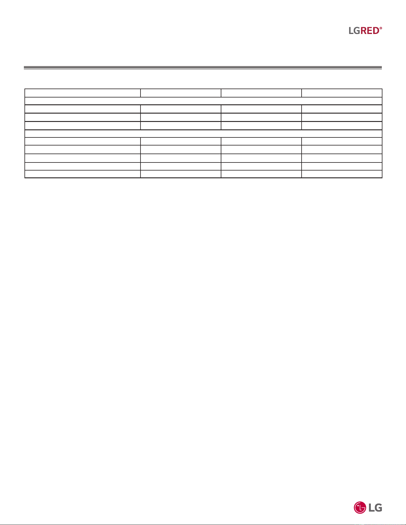
Table 9: .80;$$(I¿FLHQF\5DWLQJV
1,2
Table 10: .80;$$(I¿FLHQF\5DWLQJV
1,2
System Combined With
Rated Cooling
Capacity (Btu/h)
EER2
(95°F)
SEER2
Rated Heating
Capacity (Btu/h)
COP
(47°F)
HSPF2
Low Heating
Capacity
(Btu/h)
COP
(17°F)
ENERGY
STAR
6.1
ENERGY
STAR
Cold
Climate
KUMXA181A
Non-Ducted
Indoor Units
18,000 13.5 20.0 22,000 3.60 9.8 13,900 2.59 Yes Yes
Ducted Indoor Units 17,200 12.0 17.0 22,000 3.36 9.0 13,500 2.50 Yes Yes
Mixed Non-Ducted
and
Ducted Indoor Units
17,600 12.8 18.5 22,000 3.48 9.4 13,700 2.55 Yes Yes
Table 11: .80;$$(I¿FLHQF\5DWLQJV
1,2
System Combined With
Rated Cooling
Capacity (Btu/h)
EER2
(95°F)
SEER2
Rated Heating
Capacity (Btu/h)
COP
(47°F)
HSPF2
Low Heating
Capacity
(Btu/h)
COP
(17°F)
ENERGY
STAR
6.1
ENERGY
STAR
Cold
Climate
KUMXA241A
Non-Ducted
Indoor Units
24,000 13.5 21.0 26,000 3.66 9.8 17,800 2.80 Yes Yes
Ducted Indoor Units 22,000 12.5 18.5 24,000 3.63 9.5 15,000 2.80 Yes Yes
Mixed Non-Ducted
and
Ducted Indoor Units
23,000 13.0 19.8 25,000 3.65 9.7 16,400 2.80 Yes Yes
System Combined With
Rated Cooling
Capacity (Btu/h)
EER2
(95°F)
SEER2
Rated Heating
Capacity (Btu/h)
COP
(47°F)
HSPF2
Low Heating
Capacity
(Btu/h)
COP
(17°F)
ENERGY
STAR
6.1
ENERGY
STAR
Cold
Climate
KUMXA301A
Non-Ducted
Indoor Units
28,400 12.5 20.0 30,000 3.74 9.8 19.900 2.90 Yes Yes
Ducted Indoor Units 24,600 11.7 18.5 30,000 3.74 9.5 19.900 2.90 Yes Yes
Mixed Non-Ducted
and
Ducted Indoor Units
26,500 12.1 19.3 30,000 3.74 9.7 19.900 2.90 Yes Yes
1
&DSDFLW\LVUDWHGIWDERYHVHDOHYHOZLWKDIWOHYHOGLIIHUHQFHEHWZHHQ2'8DQG,'8VDQGWKHIROORZLQJUHIULJHUDQWSLSHOHQJWKV
.80;$$IW[ IW
.80;$$IW[ IW
.80;$$IW[ IW
$OOFDSDFLWLHVDUHQHWZLWKDFRPELQDWLRQUDWLREHWZHHQ±
5DWHGFRROLQJFDSDFLW\UDWLQJREWDLQHGZLWKDLUHQWHULQJWKHLQGRRUXQLWDW)GU\EXOE'%DQG)ZHWEXOE:%DQGRXWGRRUDPELHQWFRQGLWLRQV
RI)GU\EXOE'%DQG)ZHWEXOE:%
5DWHGKHDWLQJFDSDFLW\UDWLQJREWDLQHGZLWKDLUHQWHULQJWKHLQGRRUXQLWDW)GU\EXOE'%DQG)ZHWEXOE:%DQGRXWGRRUDPELHQWFRQGLWLRQV
RI)GU\EXOE'%DQG)ZHWEXOE:%
2
5DWHGFDSDFLW\LVFHUWL¿HGXQGHU$+5,6WDQGDUG((56((5&23DQG+63)DUHVXEMHFWWRFKDQJH6HHZZZDKULQHWRUJIRUWKH
ODWHVWYDOXHV
$WOHDVWWZRLQGRRUXQLWVPXVWEHFRQQHFWHG)RUDOORFDWHGFDSDFLW\LQIRUPDWLRQVHHWKHFRPELQDWLRQWDEOHVLQWKH0XOWL)0XOWL)0$;ZLWK
/*5('&RPELQDWLRQ'DWD0DQXDORQZZZOJKYDFFRP)RUSHUIRUPDQFHGDWDVHH0XOWL)0XOWL)0$;ZLWK/*5('3HUIRUPDQFH'DWD0DQXDO
RQZZZOJKYDFFRP
'XHWRRXUSROLF\RIFRQWLQXRXVSURGXFWLQQRYDWLRQVRPHVSHFL¿FDWLRQVPD\FKDQJHZLWKRXWQRWL¿FDWLRQ
©
/*(OHFWURQLFV86$,QF(QJOHZRRG&OLIIV1-$OOULJKWVUHVHUYHG³/*´LVDUHJLVWHUHGWUDGHPDUNRI/*&RUS
20
R32 Multi F and Multi F MAX with LGRED° Outdoor Unit Engineering Manual
MULTI
F
MAX
MULTI
F
WITH
MULTI F WITH LGRED° OUTDOOR UNIT
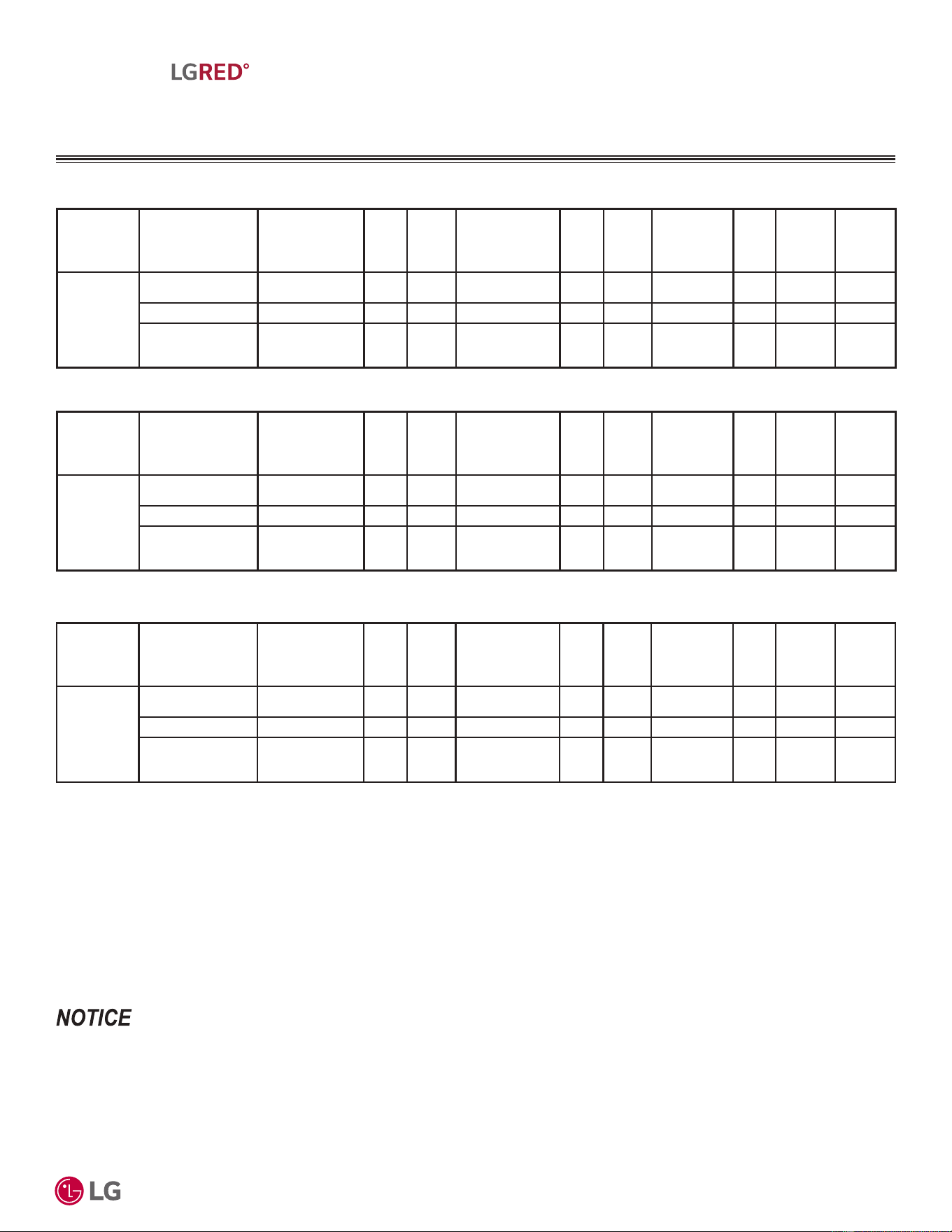
(OHFWULFDO'DWD
Nominal
Tons
Unit Model
No.
Hertz Voltage
Voltage
Range
(Min. to Max.)
MCA MOP LRA
Compressor
Quantity
Compressor
Motor RLA
Outdoor Fan Motor
Indoor Fan
Motor
kW FLA FLA
1.5 KUMXA181A
60 208 - 230 187 - 253
22.7 30 23 1 17.0 0.124 0.65 0.80
2.0 KUMXA241A 23.1 30 23 1 17.0 0.124 0.65 1.20
2.5 KUMXA301A 23.5 30 23 1 17.0 0.124 0.65 1.60
Voltage tolerance is ±10%.
Maximum allowable voltage unbalance is 2%.
MCA = Minimum Circuit Ampacity.
Maximum Overcurrent Protection (MOP) is calculated as follows: (Largest motor FLA x 2.25) + (Sum of
other motor FLA) rounded down to the nearest standard fuse size.
LRA = (Locked Rotor Amps)
RLA = Rated Load Amps.
FLA = Full Load Amps.
Table 12: Electrical Data.
Indoor Fan Motor (FLA) is based on the max. combination of IDUs.
The maximum combination for each outdoor unit is:
- 18,000 ODU (KUMXA181A): 12,000 IDU x 2
- 24,000 ODU (KUMXA241A): 12,000 IDU x 2 + 9,000 IDU x 1
- 30,000 ODU (KUMXA301A): 12,000 IDU x 3
'XHWRRXUSROLF\RIFRQWLQXRXVSURGXFWLQQRYDWLRQVRPHVSHFL¿FDWLRQVPD\FKDQJHZLWKRXWQRWL¿FDWLRQ
©
/*(OHFWURQLFV86$,QF(QJOHZRRG&OLIIV1-$OOULJKWVUHVHUYHG³/*´LVDUHJLVWHUHGWUDGHPDUNRI/*&RUS
21
R32 Multi F with LGRED° Outdoor Unit Product Data
MULTI
F
MAX
MULTI
F
WITH
MULTI F WITH LGRED° OUTDOOR UNIT
Table 13: Functions, Controls, Options, and Accessories.
Functions KUMXA181A KUMXA241A KUMXA301A
Reliability
Defrost / Deicing ¥¥¥
High Pressure Switch ¥¥¥
Restart Delay (Three [3] Minutes) ¥¥¥
Self Diagnosis ¥¥¥
Soft Start ¥¥¥
Test Function ¥¥¥
Convenience
Night Silent Operation ¥¥¥
Wiring Error Check ¥¥¥
Peak Control ¥¥¥
Mode Lock ¥¥¥
Forced Cooling Operation (Outdoor Unit) ¥¥¥
Central
Controllers
PI-485 Built-In Bulit-In Built-In
Integration
Solution
MultiSITE Communications Manager ż3%$&1%75$ ż3%$&1%75$ ż3%$&1%75$
ACP 5 BACnet® Gateway ż3$&3$ ż3$&3$ ż3$&3$
LonWorks® Gateway ż=+:/21:. ż=+:/21:. ż=+:/21:.
Central
Controllers
AC Smart 5 ż3$&6$ ż3$&6$ ż3$&6$
ACP 5 ż3$&3$ ż3$&3$ ż3$&3$
Installation
Y-Branch X X X
Header Branch X X X
Air Guide X X X
Other
Power Distribution Indication (PDI) Premium ż3418'6 ż3418'6 ż3418'6
Low Ambient Wind Baffle Kit
ż=/$%*3$
(Logical Operation)
ż=/$%*3$
(Logical Operation)
ż=/$%*3$
(Logical Operation)
Drain Pan Heater Built-In Bulit-In Built-In
LG Monitoring View (LGMV) for Computers ż35&7,/ ż35&7,/ ż35&7,/
Mobile LGMV for Android® Smartphones /
Tablets or for iOS® Tablets
ż3/*09: ż3/*09: ż3/*09:
)XQFWLRQV&RQWUROV2SWLRQVDQG$FFHVVRULHV
¥6WDQGDUG)HDWXUH
O: Option. Optional accessories must be purchased separately.
X: Not Available
(BACnet is a registered trademark of ASHRAE. LonWorks is a registered trademark of Echelon Corp.
Android is a registered trademark of Google LLC. iOS is a registered trademark of Cisco Systems, Inc.
'XHWRRXUSROLF\RIFRQWLQXRXVSURGXFWLQQRYDWLRQVRPHVSHFL¿FDWLRQVPD\FKDQJHZLWKRXWQRWL¿FDWLRQ
©
/*(OHFWURQLFV86$,QF(QJOHZRRG&OLIIV1-$OOULJKWVUHVHUYHG³/*´LVDUHJLVWHUHGWUDGHPDUNRI/*&RUS
22
R32 Multi F and Multi F MAX with LGRED° Outdoor Unit Engineering Manual
MULTI
F
MAX
MULTI
F
WITH
MULTI F WITH LGRED° OUTDOOR UNIT
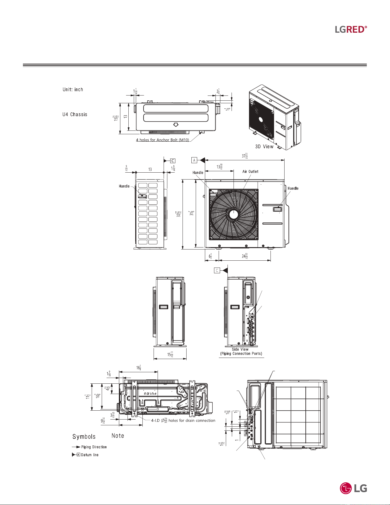
'LPHQVLRQV
Figure 4: KUMXA181A, KUMXA241A, KUMXA301A Dimensions.
Liquid-
Piping
Service
Valve
Vapor
Piping
Service
Valve
Liquid Piping
Connection
(Flare)
Vapor Piping
Connection
(Flare)
ODU-IDU Connection
Communication
Wiring Access
Hole
ODU-IDU Connection
Power Wiring Access Hole
Model: KUMXA181A,
KUMXA241A, and
KUMXA301A
1. Unit must be installed in compliance with the installation manual.
2. Unit must be grounded in accordance with the local or state
regulations and applicable national codes.
All field-supplied electrical components and materials must
comply with the local, state, and national codes.
4. Electrical characteristics must be considered for electrical work and
design. The capacity of power cable and circuit breaker for the
outdoor unit must follow local, state, national, and manufacturer
requirements.
3.
'XHWRRXUSROLF\RIFRQWLQXRXVSURGXFWLQQRYDWLRQVRPHVSHFL¿FDWLRQVPD\FKDQJHZLWKRXWQRWL¿FDWLRQ
©
/*(OHFWURQLFV86$,QF(QJOHZRRG&OLIIV1-$OOULJKWVUHVHUYHG³/*´LVDUHJLVWHUHGWUDGHPDUNRI/*&RUS
23
R32 Multi F with LGRED° Outdoor Unit Product Data
MULTI
F
MAX
MULTI
F
WITH
MULTI F WITH LGRED° OUTDOOR UNIT
&HQWHURI*UDYLW\&RUQHU:HLJKWV
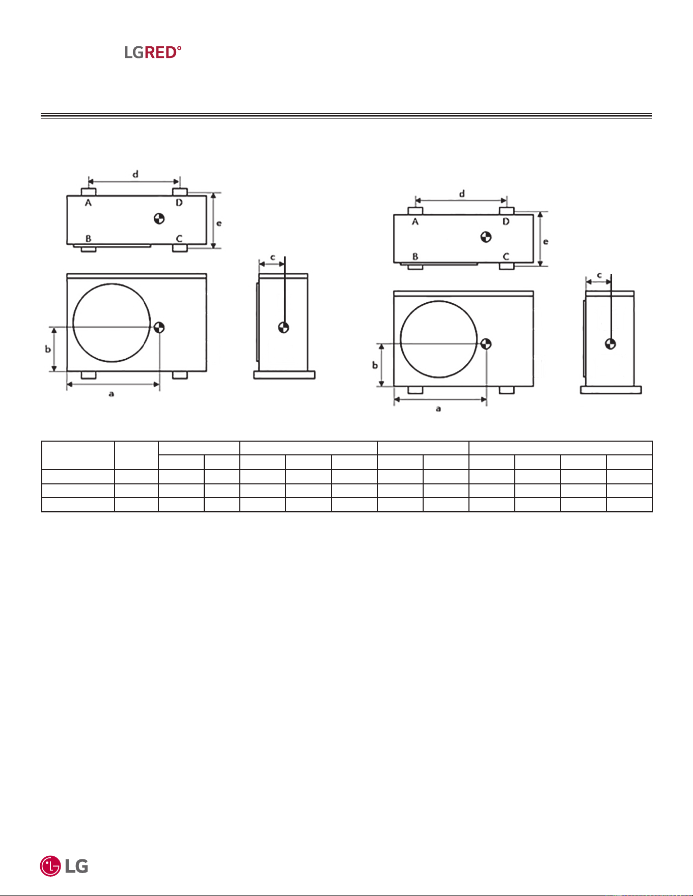
Figure 5: KUMXA181A, KUMXA241A, and KUMXA301A Center of Gravity and Corner Weight Diagram (Appearance may differ than what is depicted
below).
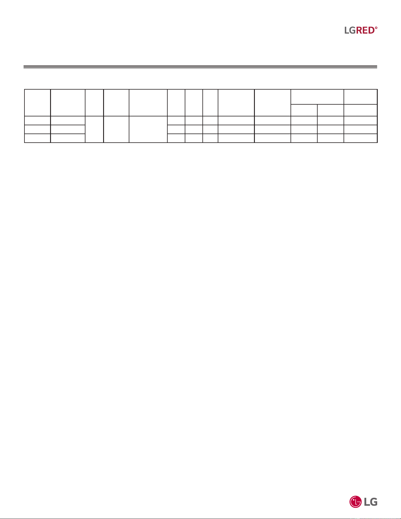
Table 14: KUMXA181A, KUMXA241A, KUMXA301A Center of Gravity and Corner Weights.
Model No. Frame
Weight (lb.) Center of Gravity (in.) Leg (in.) Corner Weight (lb.)
Shipping Net a b c d e A B C D
KUMXA181A U36A 156.5 140.0 23-7/32 12-19/32 5-29/32 24-13/32 14-3/16 18.5 29.1 56.6 35.9
KUMXA241A U36A 156.5 140.0 23-7/32 12-19/32 5-29/32 24-13/32 14-3/16 18.5 29.1 56.6 35.9
KUMXA301A U36A 156.5 140.0 23-7/32 12-19/32 5-29/32 24-13/32 14-3/16 18.5 29.1 56.6 35.9
'XHWRRXUSROLF\RIFRQWLQXRXVSURGXFWLQQRYDWLRQVRPHVSHFL¿FDWLRQVPD\FKDQJHZLWKRXWQRWL¿FDWLRQ
©
/*(OHFWURQLFV86$,QF(QJOHZRRG&OLIIV1-$OOULJKWVUHVHUYHG³/*´LVDUHJLVWHUHGWUDGHPDUNRI/*&RUS
24
R32 Multi F and Multi F MAX with LGRED° Outdoor Unit Engineering Manual
MULTI
F
MAX
MULTI
F
WITH
MULTI F WITH LGRED° OUTDOOR UNIT
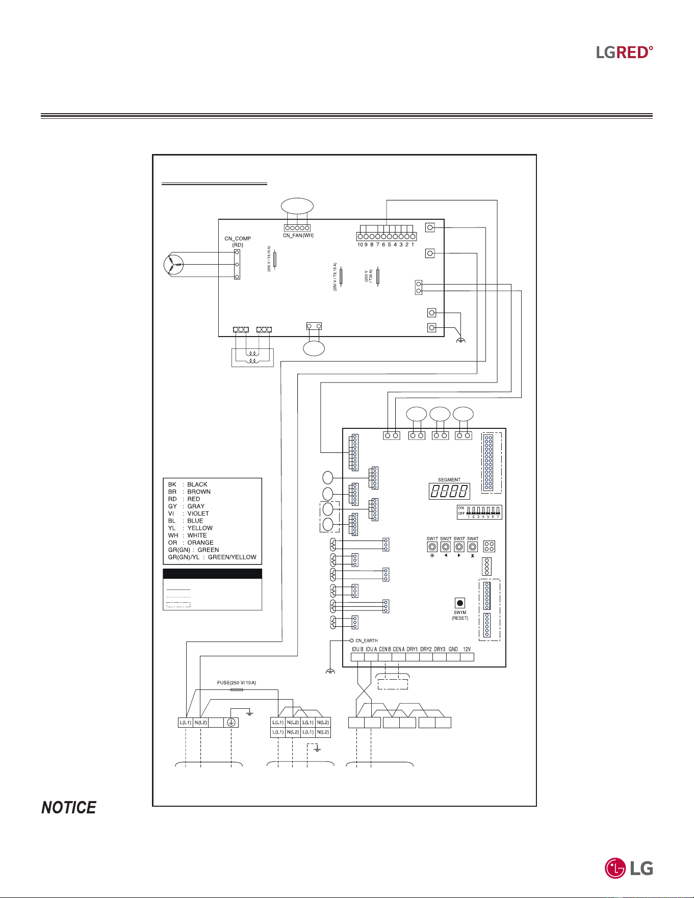
Figure 6: KUMXA181A, KUMXA241A, and KUMXA301A Wiring Diagram.
.80;$$FDQVXSSRUWQRPRUHWKDQWZRLQGRRUXQLWV.80;$$FDQVXSSRUWWZRRUWKUHHLQGRRUXQLWV.80;$$FDQVXSSRUWWZRWKUHHRU
IRXULQGRRUXQLWV(QVXUHWKHFRPPXQLFDWLRQZLULQJDQGSRZHUZLULQJIURPWKHRXWGRRUXQLWWRWKHLQGRRUXQLWVLVLQVWDOOHGFRUUHFWO\IRUWKHV\VWHPDQG
WKHFKRVHQDSSOLFDWLRQ
:LULQJ'LDJUDP
Wiring Diagram
Compressor
Fan
Motor
YL
CN_MAIN
(WH)
BK
BK
CN_PRESS_SW_WH
CN_INPUT
_BROWN
CN_INPUT
_BLUE
CN_EARTH1
CN_EARTH2
CN_REACTOR
_OUT(RD)
CN_REACTOR
_IN(BL)
U
V
W
RD
BL
U
V
W
RD BLWH BK
Pressure
Switch
INVERTER
PCB
USE COPPER SUPPLY WIRES.
MEZ68866138_Rev.01 081624
MEZ68866138
Optional or Factory installed*
Field Wiring
Factory Wiring
•
INFORMATION
BR
BL
FUSE
FUSE
FUSE
CN_SUB1_OR
BK
CN_
LGMV_V
SW5T (DIP SW)
CN_IO_WH
CN_LGMV
CN6_BK
Central
Power Supply
CN_AC
_POWER
_WH
CN1_YL CN2_BK CN3_BL
MAIN
PCB
Cond.
Mid
Suction
Discharge
CN9_RD CN8_YL CN7_VI
CN4_BR
CN5_GN
Cond.
Out
Air
Pressure
BL
OR
BL
BR
BR
BL
GN/YL
CN_EEV4_RD CN_EEV2_BL
EEV B
CN_EEV3_YL CN_EEV1_WH
*
*
CN_MB_WHCN_AI_WH
*
Basepan
Heater
BL
OR
CN_INV
EEV A
EEV CEEV D
Hot Gas
Valve
4 Way
Valve
3(A) 4(B)
3(A) 4(B)
3(A) 4(B)
OR
BL
F1X F2X
F2S
F1G
To Indoor Unit
Power Supply
To Indoor Unit
Communication
Dedicated circuit is field supplied.
* This function can be optional or factory installed
depending on the model.
*Optional parts are sold separately.
Connect the power wiring and communication wiring
according to the number of indoor units installed.
10 / 24
'XHWRRXUSROLF\RIFRQWLQXRXVSURGXFWLQQRYDWLRQVRPHVSHFL¿FDWLRQVPD\FKDQJHZLWKRXWQRWL¿FDWLRQ
©
/*(OHFWURQLFV86$,QF(QJOHZRRG&OLIIV1-$OOULJKWVUHVHUYHG³/*´LVDUHJLVWHUHGWUDGHPDUNRI/*&RUS
25
R32 Multi F with LGRED° Outdoor Unit Product Data
MULTI
F
MAX
MULTI
F
WITH
MULTI F WITH LGRED° OUTDOOR UNIT
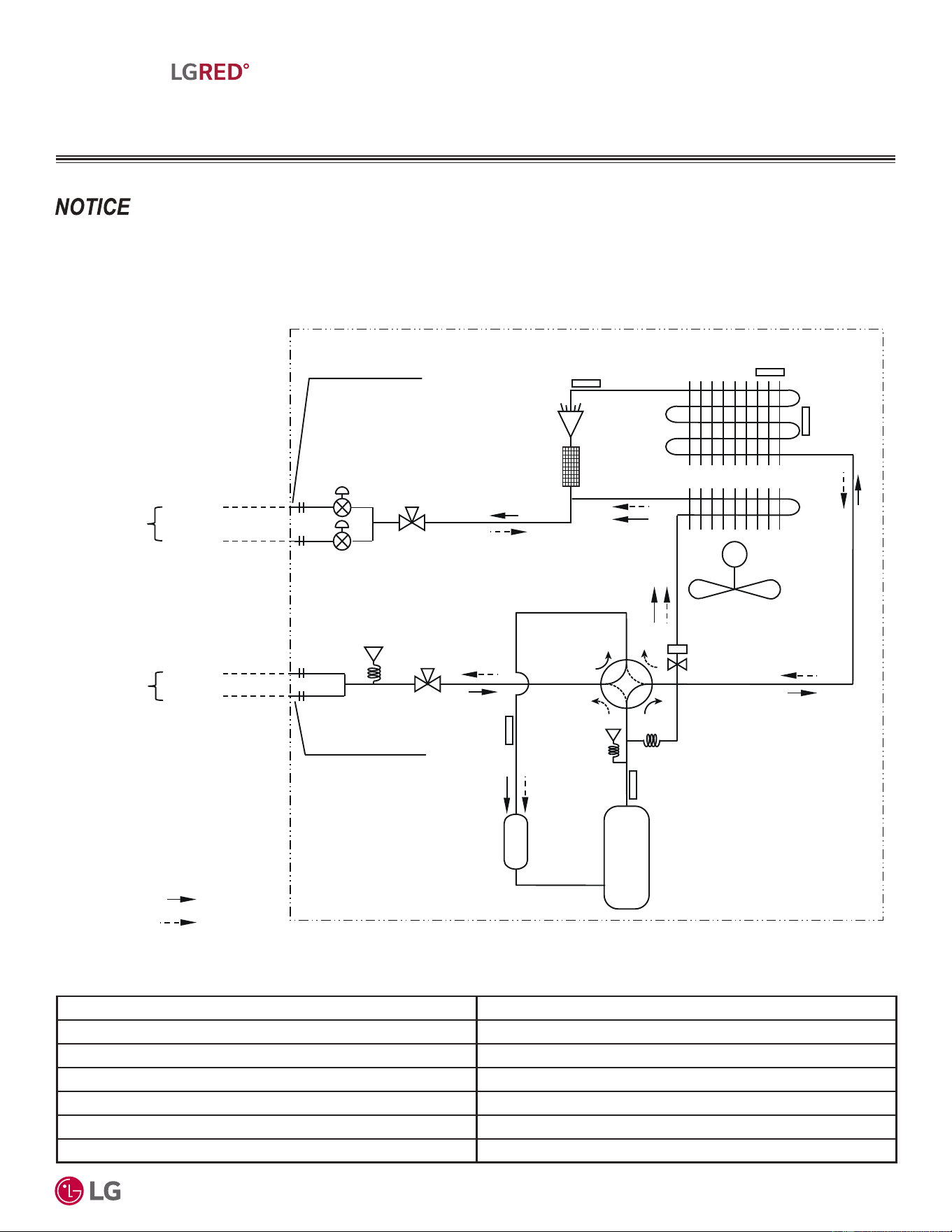
Figure 7: KUMXA181A Refrigerant Flow Diagram.
9DULRXVWRROVDUHDYDLODEOHWRDVVLVWLQSURSHUO\GHVLJQLQJ/*5VSOLWV\VWHPV5HIHUWRWKH³5$SSOLFDWLRQ*XLGH´WKH³6LPSOH&DOFXODWRUIRU&D-
SDFLW\5HIULJHUDQW&KDUJHDQG(63´WKH³/*$LU&RQGLWLRQHU7HFKQLFDO6ROXWLRQV´/$76VRIWZDUHSURJUDPDQGWKHORFDO/*6DOHV5HSUHVHQWDWLYH
5HIULJHUDQW)ORZ'LDJUDP
Table 15: KUMXA181A Thermistor Details.
M
Discharge
Temperature
Thermistor
Suction
Temperature
Thermistor
Inverter
Accumulator
Compressor
Electronic
Expansion
Valve
Condenser Out
Temperature
Thermistor
Inlet Air
Temperature
Thermistor
Outdoor Unit
Ø1/4 (6.35)
Flare Connection
Ø3/8 (9.52)
Flare Connection
Condensing
Temperature
Thermistor
: Cooling
: Heating
Main SVC V/V
Main SVC V/V
Pressure
Sensor
Pressure
Switch
ROOM A
ROOM B
Field Piping
Vapor
Ø3/8 (9.52)
or Ø1/2 (12.7)
ROOM A
Field Piping
Liquid
Ø1/4 (6.35)
ROOM B
Hotgas Valve
Unit: Inch (mm)
Description PCB Connector
Condenser Outlet Temperature Thermistor CN_C_PIPE
Condensing Temperature Thermistor CN_MID
Inlet Air Temperature Thermistor CN_AIR
Discharge Temperature Thermistor CN_DISCHARGE
Suction Temperature Thermistor CN_SUCTION
Pressure Sensor CN_H_PRESS
'XHWRRXUSROLF\RIFRQWLQXRXVSURGXFWLQQRYDWLRQVRPHVSHFL¿FDWLRQVPD\FKDQJHZLWKRXWQRWL¿FDWLRQ
©
/*(OHFWURQLFV86$,QF(QJOHZRRG&OLIIV1-$OOULJKWVUHVHUYHG³/*´LVDUHJLVWHUHGWUDGHPDUNRI/*&RUS
26
R32 Multi F and Multi F MAX with LGRED° Outdoor Unit Engineering Manual
MULTI
F
MAX
MULTI
F
WITH
MULTI F WITH LGRED° OUTDOOR UNIT
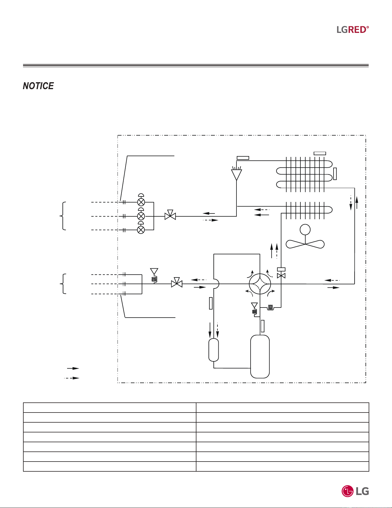
Figure 8: KUMXA241A Refrigerant Flow Diagram.
9DULRXVWRROVDUHDYDLODEOHWRDVVLVWLQSURSHUO\GHVLJQLQJ/*5VSOLWV\VWHPV5HIHUWRWKH³5$SSOLFDWLRQ*XLGH´WKH³6LPSOH&DOFXODWRUIRU&D-
SDFLW\5HIULJHUDQW&KDUJHDQG(63´WKH³/*$LU&RQGLWLRQHU7HFKQLFDO6ROXWLRQV´/$76VRIWZDUHSURJUDPDQGWKHORFDO/*6DOHV5HSUHVHQWDWLYH
5HIULJHUDQW)ORZ'LDJUDP
Table 16: KUMXA241A Thermistor Details.
M
Discharge
Temperature
Thermistor
Suction
Temperature
Thermistor
Inverter
Accumulator
Compressor
Electronic
Expansion
Valve
Condenser Out
Temperature
Thermistor
Inlet Air
Temperature
Thermistor
Outdoor Unit
Ø1/4 (6.35)
Flare Connection
Ø3/8 (9.52)
Flare Connection
Condensing
Temperature
Thermistor
: Cooling
: Heating
Main SVC V/V
Main SVC V/V
Pressure
Sensor
Pressure
Switch
ROOM A
Field Piping
Liquid
Ø1/4 (6.35)
ROOM B
ROOM C
ROOM A
ROOM B
Field Piping
Vapor
Ø3/8 (9.52)
or Ø1/2 (12.7)
ROOM C
Hotgas Valve
Unit: Inch (mm)
Description PCB Connector
Condenser Outlet Temperature Thermistor CN_C_PIPE
Condensing Temperature Thermistor CN_MID
Inlet Air Temperature Thermistor CN_AIR
Discharge Temperature Thermistor CN_DISCHARGE
Suction Temperature Thermistor CN_SUCTION
Pressure Sensor CN_H_PRESS
'XHWRRXUSROLF\RIFRQWLQXRXVSURGXFWLQQRYDWLRQVRPHVSHFL¿FDWLRQVPD\FKDQJHZLWKRXWQRWL¿FDWLRQ
©
/*(OHFWURQLFV86$,QF(QJOHZRRG&OLIIV1-$OOULJKWVUHVHUYHG³/*´LVDUHJLVWHUHGWUDGHPDUNRI/*&RUS
27
R32 Multi F with LGRED° Outdoor Unit Product Data
MULTI
F
MAX
MULTI
F
WITH
MULTI F WITH LGRED° OUTDOOR UNIT
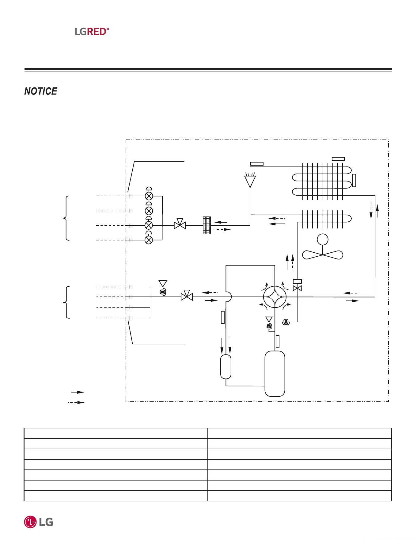
Figure 9: KUMXA301A Refrigerant Flow Diagram.
9DULRXVWRROVDUHDYDLODEOHWRDVVLVWLQSURSHUO\GHVLJQLQJ/*5VSOLWV\VWHPV5HIHUWRWKH³5$SSOLFDWLRQ*XLGH´WKH³6LPSOH&DOFXODWRUIRU&D-
SDFLW\5HIULJHUDQW&KDUJHDQG(63´WKH³/*$LU&RQGLWLRQHU7HFKQLFDO6ROXWLRQV´/$76VRIWZDUHSURJUDPDQGWKHORFDO/*6DOHV5HSUHVHQWDWLYH
5HIULJHUDQW)ORZ'LDJUDP
Table 17: KUMXA301A Thermistor Details.
M
Discharge
Temperature
Thermistor
Suction
Temperature
Thermistor
Inverter
Accumulator
Compressor
Electronic
Expansion
Valve
Condenser Out
Temperature
Thermistor
Inlet Air
Temperature
Thermistor
Outdoor Unit
Ø1/4 (6.35)
Flare Connection
Ø3/8 (9.52)
Flare Connection
Condensing
Temperature
Thermistor
ROOM A
ROOM A
ROOM B
Field Piping
Liquid
Ø
1/4 (6.35)
Field Piping
Vapor
Ø3/8 (9.52)
or Ø1/2 (12.7)
: Cooling
: Heating
ROOM B
ROOM C
ROOM D
Main SVC V/V
ROOM C
ROOM D
Main SVC V/V
Pressure
Sensor
Hotgas Valve
Pressure
Switch
Unit: Inch (mm)
Description PCB Connector
Condenser Outlet Temperature Thermistor CN_C_PIPE
Condensing Temperature Thermistor CN_MID
Inlet Air Temperature Thermistor CN_AIR
Discharge Temperature Thermistor CN_DISCHARGE
Suction Temperature Thermistor CN_SUCTION
Pressure Sensor CN_H_PRESS
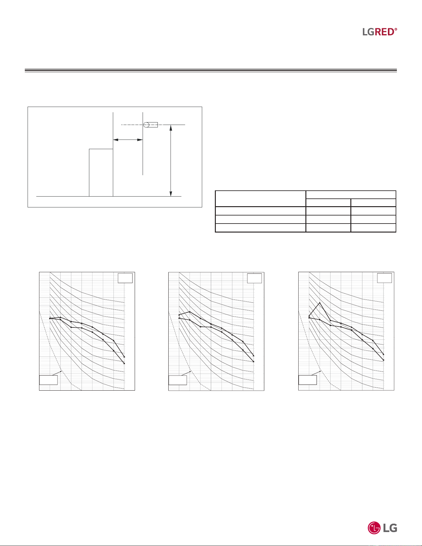
'XHWRRXUSROLF\RIFRQWLQXRXVSURGXFWLQQRYDWLRQVRPHVSHFL¿FDWLRQVPD\FKDQJHZLWKRXWQRWL¿FDWLRQ
©
/*(OHFWURQLFV86$,QF(QJOHZRRG&OLIIV1-$OOULJKWVUHVHUYHG³/*´LVDUHJLVWHUHGWUDGHPDUNRI/*&RUS
28
R32 Multi F and Multi F MAX with LGRED° Outdoor Unit Engineering Manual
MULTI
F
MAX
MULTI
F
WITH
MULTI F WITH LGRED° OUTDOOR UNIT
Sound Pressure Levels
Figure 10: Acoustic Measurement Location.
• 0HDVXUHPHQWWDNHQƍDERYHILQLVKHGIORRUDQGDWDGLVWDQFHRI
ƍIURPIDFHRIXQLW
• Measurements taken with no attenuation and units operating at full
load normal operating condition.
• Sound level will vary depending on a range of factors such as
construction (acoustic absorption coefficient) of particular area in
which the equipment is installed.
• Sound level may be increased in static pressure mode or if air
guide is used.
• Sound pressure levels are measured in dB(A)±1.
• Tested in anechoic chamber per ISO Standard 3745.
Model No.
Sound Pressure Levels (dB[A])
Cooling Heating
KUMXA181A 50 54
KUMXA241A 52 55
KUMXA301A 52 55
Table 18: Sound Pressure Levels (dB[A]).
Figure 11: Sound Pressure Level Diagrams.
4.9 feet
3.3 feet
Microphone
45
50
55
60
65
70
75
80
n
d Pressure Level (dB = 20ȝPa )
NC-45
NC-50
NC-55
NC-60
NC-65
Ŷ Cooling
Ÿ Heating
10
15
20
25
30
35
40
63 125 250 500 1000 2000 4000 8000
Octave Band Sou
n
Octave Band Center Frequency (Hz)
NC-15
NC-20
NC-25
NC-30
NC-35
NC-40
Approximate
Hearing
KUMXA181A
45
50
55
60
65
70
75
80
n
d Pressure Level (dB = 20ȝPa )
NC-45
NC-50
NC-55
NC-60
NC-65
Ŷ Cooling
Ÿ Heating
10
15
20
25
30
35
40
63 125 250 500 1000 2000 4000 8000
Octave Band Sou
n
Octave Band Center Frequency (Hz)
NC-15
NC-20
NC-25
NC-30
NC-35
NC-40
Approximate
Hearing
KUMXA241A
45
50
55
60
65
70
75
80
n
d Pressure Level (dB = 20ȝPa )
NC-45
NC-50
NC-55
NC-60
NC-65
Ŷ Cooling
Ÿ Heating
10
15
20
25
30
35
40
63 125 250 500 1000 2000 4000 8000
Octave Band Sou
n
Octave Band Center Frequency (Hz)
NC-15
NC-20
NC-25
NC-30
NC-35
NC-40
Approximate
Hearing
KUMXA301A
$FRXVWLF'DWD
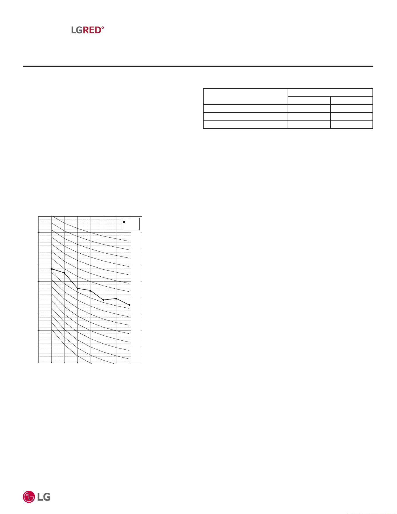
'XHWRRXUSROLF\RIFRQWLQXRXVSURGXFWLQQRYDWLRQVRPHVSHFL¿FDWLRQVPD\FKDQJHZLWKRXWQRWL¿FDWLRQ
©
/*(OHFWURQLFV86$,QF(QJOHZRRG&OLIIV1-$OOULJKWVUHVHUYHG³/*´LVDUHJLVWHUHGWUDGHPDUNRI/*&RUS
29
R32 Multi F with LGRED° Outdoor Unit Product Data
MULTI
F
MAX
MULTI
F
WITH
MULTI F WITH LGRED° OUTDOOR UNIT
$FRXVWLF'DWD
Sound Power Levels
• Data is valid under diffuse field conditions.
• Data is valid under nominal operating conditions.
• Sound power level is measured using rated conditions, and tested
in a reverberation room per ISO 3741 standards.
• Sound level will vary depending on a range of factors such as
construction (acoustic absorption coefficient) of particular area in
which the equipment is installed.
• 5HIHUHQFHDFRXVWLFLQWHQVLW\G% (ȝ:P
2
Table 19: Sound Power Levels (dB[A]).
Model No.
Sound Power Levels (dB[A])
Cooling Heating
KUMXA181A 64 66
KUMXA241A 64 66
KUMXA301A 64 66
Figure 12: Cooling Sound Power Level Diagram.
KUMXA181A,
KUMXA241A,
KUMXA301A
10
20
30
40
50
60
70
80
90
100
125 250 500 1000 2000 4000 8000
Sound Power Level (0dB = 10E-6ȝW/m
2
)
NR-70
NR-65
NR-60
NR-55
Octave Band Center Frequency (Hz)
NR-50
NR-45
NR-40
NR-35
NR-30
NR-75
NR-25
NR-20
NR-80
NR-85
NR-90
Cooling

MULTI F MAX WITH
LGRED° OUTDOOR
UNIT PRODUCT DATA
Mechanical Specifications on page 31
General Data on page 32
Electrical Data on page 35
Functions, Controls, Options, and Accessories on page 36
Dimensions on page 37
&HQWHURI*UDYLW\&RUQHU:HLJKWVRQSDJH
Wiring Diagram on page 39
Refrigerant Flow Diagrams on page 40
Acoustic Data on page 41
'XHWRRXUSROLF\RIFRQWLQXRXVSURGXFWLQQRYDWLRQVRPHVSHFL¿FDWLRQVPD\FKDQJHZLWKRXWQRWL¿FDWLRQ
©
/*(OHFWURQLFV86$,QF(QJOHZRRG&OLIIV1-$OOULJKWVUHVHUYHG³/*´LVDUHJLVWHUHGWUDGHPDUNRI/*&RUS
31
R32 Multi F MAX with LGRED° Outdoor Unit Product Data
MULTI
F
MAX
MULTI
F
WITH
MULTI F MAX WITH LGRED°
OUTDOOR UNIT
0HFKDQLFDO6SHFL¿FDWLRQV
Multi F MAX with LGRED Heat Pump
Units
General
A Multi F MAX with LGRED multi-zone system is comprised of one
heat pump outdoor unit connected up to eight indoor units through a
branch distribution (BD) unit using a single refrigerant piping circuit,
and includes integrated controls supplied by LG. Factory-designed
and supplied Y-branches may be used as well.
The outdoor unit is internally assembled, wired, and piped from the
factory; all LG components are manufactured in a facility registered
to ISO 9001 and ISO 14001, set by the International Organization for
Standardization (ISO). The LG Multi F MAX with LGRED multi-zone
heat pump system components comply with Underwriters Laborato-
ries (UL) 1995 Heating and Cooling Equipment Standard for Safety.
The units are certified to AHRI 210 / 240.
Temperature Ranges
The heat pump outdoor units are capable of operating in cooling
mode from 14°F to 118°F ambient dry bulb (installing an optional
Low Ambient Wind Baffle Kit will allow operation down to -4°F in
cooling mode for Multi F MAX with LGRED systems). The heat pump
outdoor units are capable of operating in heating mode from -13°F to
+64°F ambient wet bulb without additional low ambient controls.
Frame
Multi F MAX with LGRED condensing unit case is constructed from
pre-coated metal that has been tested in accordance with ASTM
B-117 salt spray procedure for a minimum of 1,000 hours. Case has
a removable front panel to allow access to major components and
control devices, and legs to secure the unit during installation.
Refrigerant System
Multi F MAX with LGRED systems have a single refrigerant circuit
field piped with a manufacturer-supplied branch distribution unit(s)
and Y-branches (if applicable) to multiple (ducted, non-ducted or
mixed) indoor units to effectively and efficiently control the heating
or cooling operation of the multi zone system. All refrigerant lines
from the outdoor unit to the branch distribution unit(s) and from the
branch distribution unit(s) to indoor units are field-installed and must
be insulated separately.
Multi F MAX with LGRED systems use R32 refrigerant. The out-
door units are equipped with a sub-cooled heat exchanger, vapor
injection, vapor bypass circuit, refrigerant strainer, check valves, oil
separator, accumulator, four-way reversing valve, electronic expan-
sion valve(s) (EEV), high side and low side refrigerant charging
ports, and a service port. The outdoor unit also includes sensors
for suction temperature, discharge temperature, high-pressure,
low-pressure, heat exchanger temperature, and outdoor temperature
conditions.
Refrigeration Oil Control
The outdoor unit has an oil separator to separate oil mixed with the
refrigerant gas during compression and return oil to the compressor.
The outdoor unit also has an oil injection mechanism to ensure a
consistent film of oil on all moving compressor parts at low speed.
Figure 13: Multi F MAX with LGRED
KUMXA361A, KUMXA421A,
KUMXA481A Outdoor Units.
Compressor
Multi F MAX with LGRED con-
densing units are equipped with
one hermetically sealed, digitally
controlled, inverter driven scroll
compressor that includes
Teflon™ coated bearings. The
inverter motor is capable of
providing a modulation range
of 10Hz to 120Hz (cooling) and
10Hz to 135Hz (heating) with
control in 1Hz increments. The
compressor is uses a factory-
charge of Polyvinyl Ether (PVE)
oil, and is mounted to avoid the
transmission of vibration.
Fan and Motors
The Multi F MAX with LGRED
outdoor unit includes two direct
drive variable speed propeller fans with Brushless Digitally Con-
trolled (BLDC) motor with a horizontal air discharge.
Fan blades are statically and dynamically balanced propeller fans
made of durable Acrylonitrile Butadiene Styrene (ABS) plastic, and
include a raised fan guard to limit contact with moving parts. The
motors have inherent overload protection, permanently lubricated
bearings, and a maximum speed up to 700 rpm in cooling, and up to
750 rpm in heating. Multi F MAX with LGRED outdoor units have a
horizontal discharge airflow.
Outdoor Unit Coil
The outdoor unit coils are factory-built of aluminum fins mechanically
bonded on copper tubing. Coils have a minimum of three rows, a
minimum of 14 fins per inch and have been factory pressure-tested.
Coil fins also have a factory applied corrosion-resistant GoldFin™
material with hydrophilic coating that has been tested in accordance
with ASTM B-117 salt spray test procedure for a minimum of 1,000
hours.
Electrical
Multi F MAX with LGRED outdoor unit have 208/230V, 1 phase,
60Hz electrical power capable of operating within ±10% of the rated
voltage.
Controls
Factory installed microprocessor controls in the outdoor unit, BD
unit(s), and indoor units perform functions to efficiently operate the
multi-zone system. Outdoor units are equipped with a central control
connection. Power wiring must be installed in a tree configuration
from the outdoor unit to the BD units, and from the BDU units to the
indoor units through a three (3) wire power cable. Communication
wiring can be installed in a tree configuration, daisy chain, or combi-
nation of both from the outdoor unit to the BD units and from the BD
units to the indoor units through a two (2) wire communication cable.
The system is capable of performing continuous operation, even
when power is turned off to an individual indoor unit.
'XHWRRXUSROLF\RIFRQWLQXRXVSURGXFWLQQRYDWLRQVRPHVSHFL¿FDWLRQVPD\FKDQJHZLWKRXWQRWL¿FDWLRQ
©
/*(OHFWURQLFV86$,QF(QJOHZRRG&OLIIV1-$OOULJKWVUHVHUYHG³/*´LVDUHJLVWHUHGWUDGHPDUNRI/*&RUS
32
R32 Multi F and Multi F MAX with LGRED° Outdoor Unit Engineering Manual
MULTI
F
MAX
MULTI
F
WITH
MULTI F MAX WITH LGRED°
OUTDOOR UNIT
*HQHUDO'DWD
Table 20: 0XOWL)0$;ZLWK/*5('2XWGRRU8QLW6SHFL¿FDWLRQV
Model Number KUMXA361A KUMXA421A KUMXA481A
Cooling Capacity (Btu/h) (Minimum ~ Rated ~ Maximum)
1
10,800~36,000~47,000 10,800~42,000~53,000 10,800~48,000~58,000
Cooling Power Input (kW) (Min.~Rated~ Max.) 0.64~2.48~4.07 0.64~3.04~4.71 0.64~3.66~5.17
Cooling Running Current (A) (Min.~Rated~ Max.) 2.9~11.2~18.5 2.9~13.8~21.3 2.9~16.6~23.4
Heating Capacity (Btu/h)
(Minimum ~ Rated ~ Maximum)
1
12,420~45,000~50,000 12,420~48,000~54,500 12,420~52,500~59,000
Heating Power Input (kW) (Min.~Rated~ Max.) 0.71~3.30~4.31 0.71~3.70~4.70 0.71~4.25~5.09
Heating Running Current (A) (Min.~Rated~ Max.) 3.2~14.9~19.5 3.2~16.8~21.3 3.2~20.0~23.0
&RQWLQXRXV2SHUDWLQJ5DQJH
2
Cooling (°F DB) 14 to 118 14 to 118 14 to 118
Heating (°F WB) -13 to +64 -13 to +64 -13 to +64
&RPSUHVVRU
Type x Quantity Scroll x 1 Scroll x 1 Scroll x 1
Oil/Type PVE PVE PVE
)DQ6LGH'LVFKDUJH
Type Propeller Propeller Propeller
Motor Output (W) x Qty. 124.2 x 2 124.2 x 2 124.2 x 2
Motor / Drive Brushless Digitally Controlled / Direct
Maximum Air Volume (CFM) 2,119 x 2 2,119 x 2 2,119 x 2
Maximum External Static Pressure (in. w.g.) 0.1 0.1 0.1
8QLW'DWD
Min. ~ Max. Number Indoor Units/System
3
2 ~ 5 2 ~ 6 2 ~ 8
Max. Number of Branch Distribution Units 2 2 2
Min. ~ Max. Allowable Total Indoor Unit Connected Capacity (Btu/h) 18,000 ~ 48,000 18,000 ~ 56,000 18,000 ~ 65,000
Sound Pressure ±3 dB(A)
4
Cooling 53 54 54
Heating 55 56 56
Net Dimensions (W x H x D [inch]) 37-13/32 x 54-11/32 x 13
Shipping Dimensions (W x H x D [inch]) 44-3/4 x 57-19/32 x 18-5/32
Net / Shipping Unit Weight (lbs.) 218.3 / 239.2 218.3 / 239.2 218.3 / 239.2
Exterior Color Codes Munsell 2.5Y 7.5/1 (RAL 7044)
Power Supply (To Outdoor Unit; V / Hz / Ø) 208 / 230V, 60, 1
Power Supply Wiring (To Outdoor Unit) (No. x AWG)
5
3 x 8 3 x 8 3 x 8
Power Wiring / Communication Wiring (ODU to BDU) (No. x AWG)
5
3 x 14 / 2 x 18 3 x 14 / 2 x 18 3 x 14 / 2 x 18
Power Wiring / Communication Wiring (BDU to IDU) (No. X AWG)
5
3 x 14 / 2 x 18 3 x 14 / 2 x 18 3 x 14 / 2 x 18
+HDW([FKDQJHU
Material and Fin Coating Copper Tube / Aluminum Fin and GoldFin™ / Hydrophilic
Rows / Columns / Fins per inch x Qty.
(2 x 32 x 14) x 2;
(1 x 32 x 14) x 2
(2 x 32 x 14) x 2;
(1 x 32 x 14) x 2
(2 x 32 x 14) x 2;
(1 x 32 x 14) x 2
5HIULJHUDQW
Type
6
/ Control R32, Electronic Expansion Valve / Outdoor Unit
Factory Charge oz. of R32 148.2 148.2 148.2
Additional Charge (oz./ft.)
Main Pipe 0.54 0.54 0.54
Branch Pipe 0.22 0.22 0.22
1
Capacity is rated with non-ducted IDUs, 0 ft. above sea level, with a 0 ft. level difference between ODU
and IDUs, and the following refrigerant pipe lengths:
KUMXA361A: 16.4 ft. Main + (16.4 ft. Branch x 5) = 98.4 ft.
KUMXA421A: 16.4 ft. Main + (16.4 ft. Branch x 6) = 114.8 ft.
KUMXA481A: 16.4 ft. Main + (16.4 ft. Branch x 8) = 147.6 ft.
All capacities are net with a combination ratio between 95 – 105%.
Rated cooling capacity obtained with air entering the indoor unit at 80ºF dry bulb (DB) and 67ºF wet
bulb (WB) and outdoor ambient conditions of 95ºF dry bulb (DB) and 75ºF wet bulb (WB).
Rated heating capacity obtained with air entering the indoor unit at 70ºF dry bulb (DB) and 60ºF wet
bulb (WB) and outdoor ambient conditions of 47ºF dry bulb (DB) and 43ºF wet bulb (WB).
2
Cooling operation range with Low Ambient Wind Baffle Kit (sold separately) is -4°F to +118°F.
3
At least one Branch Distribution Unit is required for system operation; a maximum of two can be
installed per outdoor unit with use of Y-branch accessory (ARBLN03321). At least two indoor units must
be connected. For allocated capacity information, see the combination tables in the “Multi F / Multi F
MAX with LGRED Combination Data Manual” on www.lghvac.com. For performance data, see “Multi F /
Multi F MAX with LGRED Performance Data Manual” on www.lghvac.com.
4
Sound pressure levels are tested in an anechoic chamber under ISO Standard 3745.
5
Power wiring to the outdoor unit is field supplied, solid or stranded, and must comply with the ap-
plicable local and national codes. The power / communication wiring from the outdoor unit to the branch
distribution unit, and the power wiring and communication wiring from the branch distribution unit to
the indoor unit, is field supplied and must be stranded, shielded or unshielded (if shielded, it must be
grounded to the chassis of the outdoor unit only). All wiring must comply with applicable local and
national codes. For detailed information, please refer to electrical characteristics on page 35.
6
Take appropriate actions at the end of HVAC equipment life to recover, recycle, reclaim or destroy R32
refrigerant according to applicable regulations (40 CFR Part 82, Subpart F) under section 608 of CAA.
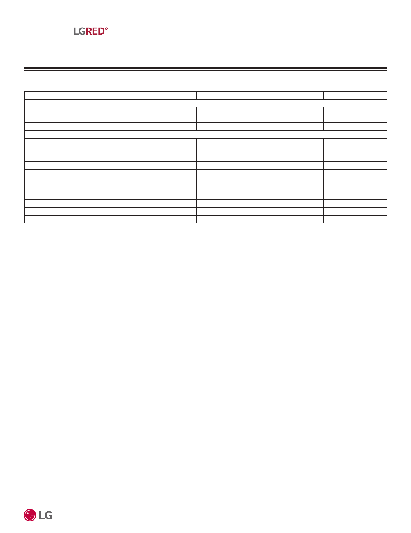
'XHWRRXUSROLF\RIFRQWLQXRXVSURGXFWLQQRYDWLRQVRPHVSHFL¿FDWLRQVPD\FKDQJHZLWKRXWQRWL¿FDWLRQ
©
/*(OHFWURQLFV86$,QF(QJOHZRRG&OLIIV1-$OOULJKWVUHVHUYHG³/*´LVDUHJLVWHUHGWUDGHPDUNRI/*&RUS
33
R32 Multi F MAX with LGRED° Outdoor Unit Product Data
MULTI
F
MAX
MULTI
F
WITH
MULTI F MAX WITH LGRED°
OUTDOOR UNIT
Model Number KUMXA361A KUMXA421A KUMXA481A
3LSLQJ
Liquid Line Connection (in., OD) x Qty. Ø3/8 Flare x 1 Ø3/8 Flare x 1 Ø3/8 Flare x 1
Vapor Line Connection (in., OD) x Qty. Ø3/4 Flare x 1 Ø3/4 Flare x 1 Ø3/4 Flare x 1
Condensation Line (O.D., I.D., in.) 1-1/4 / 1 1-1/4 / 1 1-1/4 / 1
3LSLQJ/HQJWKV
1
Maximum Total System Piping (ft.) 475.7 475.7 475.7
Piping Length (No Additional Refrigerant [ft.] Main+Branch) 49.2 + 131.2 49.2 + 131.2 49.2 + 131.2
Maximum Main Pipe Length (ODU to BDU [ft.]) 180.4 180.4 180.4
Total Branch Piping (BDU to all IDUs [ft.]) 295.3 295.3 295.3
Maximum Branch Pipe Length (Length between each
BDU and IDU [ft.])
49.2 49.2 49.2
Maximum Outdoor Unit to Indoor Unit Pipe Length (ft.) 229.6 229.6 229.6
Maximum Elevation between ODU and IDU (ft.) 98.4 98.4 98.4
Maximum Elevation between IDU and IDU (ft.) 49.2 49.2 49.2
Maximum Elevation between BDU and IDU (ft.) 32.8 32.8 32.8
Maximum Elevation between BDU and BDU (ft.) 49.2 49.2 49.2
Table 21: 0XOWL)0$;ZLWK/*5('2XWGRRU8QLW6SHFL¿FDWLRQVFRQWLQXHG
Capacity is rated with non-ducted IDUs, 0 ft. above sea level, with a 0 ft. level difference between ODU
and IDUs, and the following refrigerant pipe lengths:
KUMXA361A: 16.4 ft. Main + (16.4 ft. Branch x 5) = 98.4 ft.
KUMXA421A: 16.4 ft. Main + (16.4 ft. Branch x 6) = 114.8 ft.
KUMXA481A: 16.4 ft. Main + (16.4 ft. Branch x 8) = 147.6 ft.
All capacities are net with a combination ratio between 95 – 105%.
1
Piping lengths are equivalent.
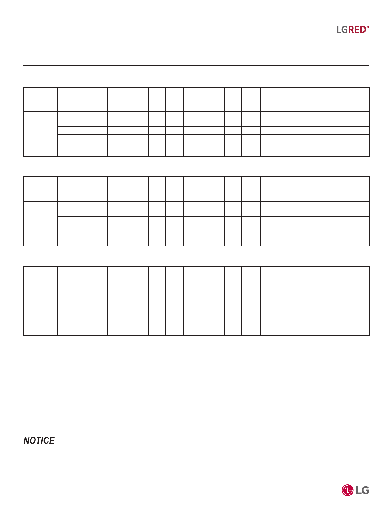
'XHWRRXUSROLF\RIFRQWLQXRXVSURGXFWLQQRYDWLRQVRPHVSHFL¿FDWLRQVPD\FKDQJHZLWKRXWQRWL¿FDWLRQ
©
/*(OHFWURQLFV86$,QF(QJOHZRRG&OLIIV1-$OOULJKWVUHVHUYHG³/*´LVDUHJLVWHUHGWUDGHPDUNRI/*&RUS
34
R32 Multi F and Multi F MAX with LGRED° Outdoor Unit Engineering Manual
MULTI
F
MAX
MULTI
F
WITH
MULTI F MAX WITH LGRED°
OUTDOOR UNIT
*HQHUDO'DWD
System Combined With
Rated Cooling
Capacity (Btu/h)
EER2
(95°F)
SEER2
Rated Heating
Capacity (Btu/h)
COP
(47°F)
HSPF2
Low Heating
Capacity (Btu/h)
COP
(17°F)
ENERGY
STAR
6.1
ENERGY
STAR
Cold
Climate
KUMXA361A
Non-Ducted
Indoor Units
36,000 14.5 22.0 45,000 4.00 11.0 29,600 2.38 Yes Yes
Ducted Indoor Units 36,000 13.5 19.0 45,000 3.57 10.0 29,600 2.76 Yes Yes
Mixed Non-Ducted
and
Ducted Indoor Units
36,000 14.0 20.5 45,000 3.77 10.5 29,600 2.75 Yes Yes
Table 22: .80;$$(I¿FLHQF\5DWLQJV
1,2
Table 23: .80;$$(I¿FLHQF\5DWLQJV
1,2
1
&DSDFLW\LVUDWHGIWDERYHVHDOHYHOZLWKDIWOHYHOGLIIHUHQFHEHWZHHQ2'8DQG,'8VDQGWKHIROORZLQJUHIULJHUDQWSLSHOHQJWKV
.80;$$IW0DLQIW%UDQFK[ IW
.80;$$IW0DLQIW%UDQFK[ IW
.80;$$IW0DLQIW%UDQFK[ IW
$OOFDSDFLWLHVDUHQHWZLWKDFRPELQDWLRQUDWLREHWZHHQ±
5DWHGFRROLQJFDSDFLW\UDWLQJREWDLQHGZLWKDLUHQWHULQJWKHLQGRRUXQLWDW)GU\EXOE'%DQG)ZHWEXOE:%DQGRXWGRRUDPELHQWFRQGLWLRQV
RI)GU\EXOE'%DQG)ZHWEXOE:%
5DWHGKHDWLQJFDSDFLW\UDWLQJREWDLQHGZLWKDLUHQWHULQJWKHLQGRRUXQLWDW)GU\EXOE'%DQG)ZHWEXOE:%DQGRXWGRRUDPELHQWFRQGLWLRQV
RI)GU\EXOE'%DQG)ZHWEXOE:%
2
5DWHGFDSDFLW\LVFHUWL¿HGXQGHU$+5,6WDQGDUG((56((5&23DQG+63)DUHVXEMHFWWRFKDQJH6HHZZZDKULQHWRUJIRUWKH
ODWHVWYDOXHV
$WOHDVWWZRLQGRRUXQLWVPXVWEHFRQQHFWHG)RUDOORFDWHGFDSDFLW\LQIRUPDWLRQVHHWKHFRPELQDWLRQWDEOHVLQWKH0XOWL)0XOWL)0$;ZLWK
/*5('&RPELQDWLRQ'DWD0DQXDORQZZZOJKYDFFRP)RUSHUIRUPDQFHGDWDVHH0XOWL)0XOWL)0$;ZLWK/*5('3HUIRUPDQFH'DWD0DQXDO
RQZZZOJKYDFFRP
Table 24: .80;$$(I¿FLHQF\5DWLQJV
1,2
System Combined With
Rated Cooling
Capacity (Btu/h)
EER2
(95°F)
SEER2
Rated Heating
Capacity (Btu/h)
COP
(47°F)
HSPF2
Low Heating
Capacity (Btu/h)
COP
(17°F)
ENERGY
STAR
6.1
ENERGY
STAR
Cold
Climate
KUMXA421A
Non-Ducted
Indoor Units
42,000 13.8 21.5 48,000 3.80 11.0 31,600 2.54 Yes Yes
Ducted Indoor Units 42,000 13.1 19.0 48,000 3.52 10.0 31,600 2.60 Yes Yes
Mixed Non-Ducted
and
Ducted Indoor Units
42,000 13.5 20.3 48,000 3.65 10.5 31,600 2.57 Yes Yes
System Combined With
Rated Cooling
Capacity (Btu/h)
EER2
(95°F)
SEER2
Rated Heating
Capacity (Btu/h)
COP
(47°F)
HSPF2
Low Heating
Capacity (Btu/h)
COP
(17°F)
ENERGY
STAR
6.1
ENERGY
STAR
Cold
Climate
KUMXA481A
Non-Ducted
Indoor Units
48,000 13.1 20.5 52,500 3.62 10.5 35,000 2.47 Yes Yes
Ducted Indoor Units 48,000 12.6 18.5 52,500 3.45 10.0 34,000 2.66 Yes Yes
Mixed Non-Ducted
and
Ducted Indoor Units
48,000 12.9 19.5 52,500 3.53 10.3 34,500 2.56 Yes Yes
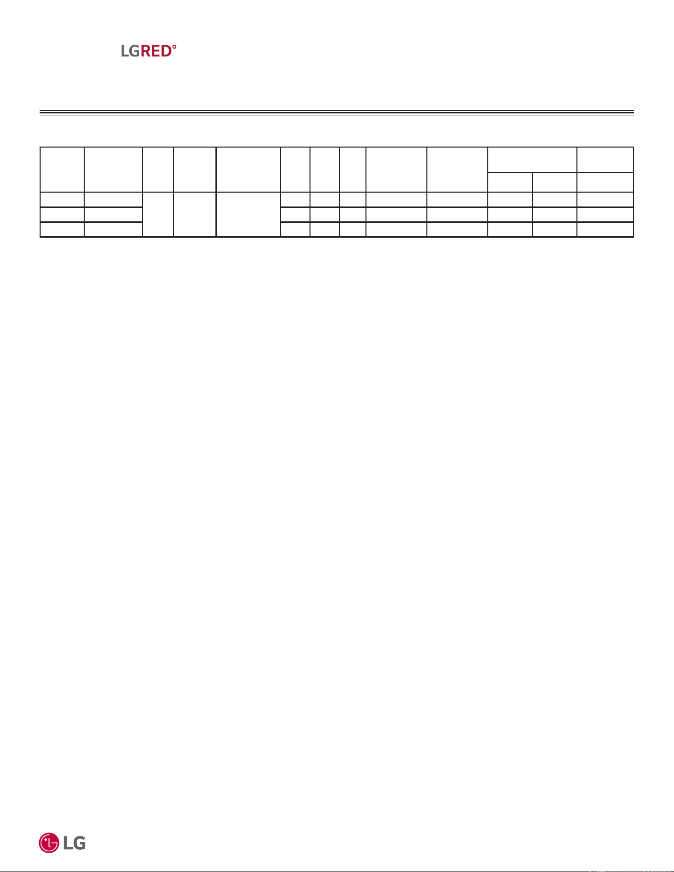
'XHWRRXUSROLF\RIFRQWLQXRXVSURGXFWLQQRYDWLRQVRPHVSHFL¿FDWLRQVPD\FKDQJHZLWKRXWQRWL¿FDWLRQ
©
/*(OHFWURQLFV86$,QF(QJOHZRRG&OLIIV1-$OOULJKWVUHVHUYHG³/*´LVDUHJLVWHUHGWUDGHPDUNRI/*&RUS
35
R32 Multi F MAX with LGRED° Outdoor Unit Product Data
MULTI
F
MAX
MULTI
F
WITH
MULTI F MAX WITH LGRED°
OUTDOOR UNIT
(OHFWULFDO'DWD
Nominal
Tons
Unit Model
No.
Hertz Voltage
Voltage
Range
(Min. to Max.)
MCA MOP LRA
Compressor
Quantity
Compressor
Motor RLA
Outdoor Fan Motor
Indoor Fan
Motor
kW FLA FLA
3.0 KUMXA361A
60 208 - 230 187 - 253
32.1 40 22 1 23.0 0.124 x 2 1.30 2.00
3.5 KUMXA421A 32.5 40 22 1 23.0 0.124 x 2 1.30 2.40
4.0 KUMXA481A 33.3 40 22 1 23.0 0.124 x 2 1.30 3.20
Table 25: Electrical Data.
Voltage tolerance is ±10%.
Maximum allowable voltage unbalance is 2%.
MCA = Minimum Circuit Ampacity.
Maximum Overcurrent Protection (MOP) is calculated as follows:
(Largest motor FLA x 2.25) + (Sum of other motor FLA) rounded
down to the nearest standard fuse size.
LRA = (Locked Rotor Amps)
RLA = Rated Load Amps.
FLA = Full Load Amps.
Indoor Fan Motor (FLA) is based on the max. combination of IDUs.
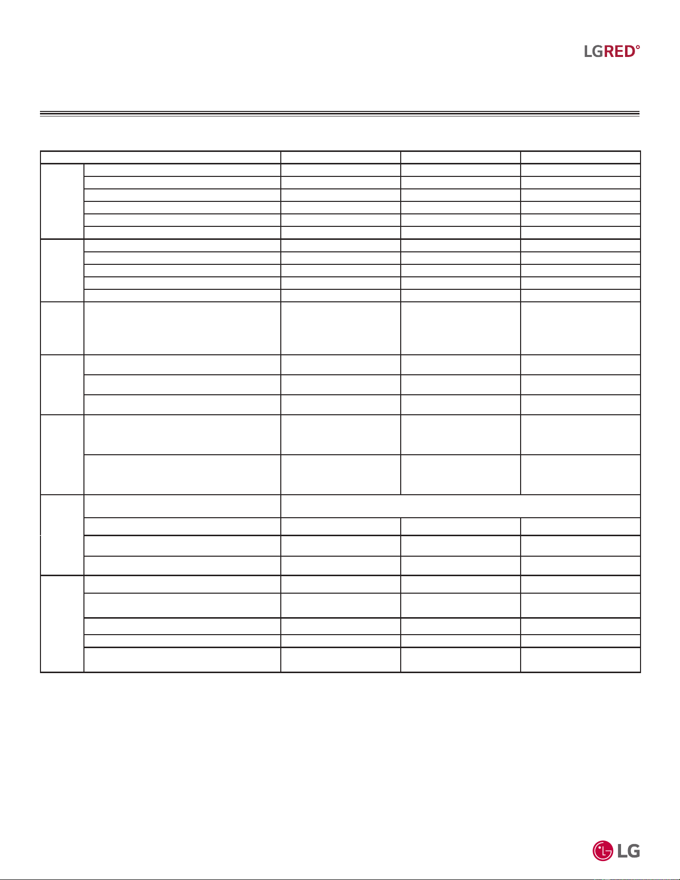
'XHWRRXUSROLF\RIFRQWLQXRXVSURGXFWLQQRYDWLRQVRPHVSHFL¿FDWLRQVPD\FKDQJHZLWKRXWQRWL¿FDWLRQ
©
/*(OHFWURQLFV86$,QF(QJOHZRRG&OLIIV1-$OOULJKWVUHVHUYHG³/*´LVDUHJLVWHUHGWUDGHPDUNRI/*&RUS
36
R32 Multi F and Multi F MAX with LGRED° Outdoor Unit Engineering Manual
MULTI
F
MAX
MULTI
F
WITH
MULTI F MAX WITH LGRED°
OUTDOOR UNIT
)XQFWLRQV&RQWUROV2SWLRQVDQG$FFHVVRULHV
Table 26: Functions, Controls, Options, and Accessories.
Functions KUMXA361A KUMXA421A KUMXA481A
Reliability
Defrost / Deicing ¥¥¥
High Pressure Switch ¥¥¥
Restart Delay (Three [3] Minutes) ¥¥¥
Self Diagnosis ¥¥¥
Soft Start ¥¥¥
Test Function ¥¥¥
Convenience
Night Silent Operation ¥¥¥
Wiring Error Check ¥¥¥
Peak Control ¥¥¥
Mode Lock ¥¥¥
Forced Cooling Operation (Outdoor Unit) ¥¥¥
Central
Controllers
Central Control Connectivity Built-In Built-In Built-In
Integration
Solution
MultiSITE Communications Manager ż3%$&1%75$ ż3%$&1%75$ ż3%$&1%75$
ACP 5 BACnet® Gateway ż3$&3$ ż3$&3$ ż3$&3$
LonWorks® Gateway ż=+:/21:. ż=+:/21:. ż=+:/21:.
Central
Controllers
AC Smart 5 ż3$&6$ ż3$&6$ ż3$&6$
ACP 5 ż3$&3$ ż3$&3$ ż3$&3$
Installation
Branch Distribution Units ż30%'=530%'=530%'=530%'=5
Y-Branch ż$5%/1 ż$5%/1 ż$5%/1
Header Branch X X X
Air Guide X X X
Other
Power Distribution Indication (PDI) Premium ż3418'6 ż3418'6 ż3418'6
Low Ambient Wind Baffle Kit
ż=/$%*3$[
(Logical Operation)
ż=/$%*3$[
(Logical Operation)
ż=/$%*3$[
(Logical Operation)
Drain Pan Heater Built-In Built-In Built-In
LG Monitoring View (LGMV) for Computers ż35&7,/ ż35&7,/ ż35&7,/
Mobile LGMV for Android® Smartphones /
Tablets or for iOS® Tablets
ż3/*09: ż3/*09: ż3/*09:
¥6WDQGDUG)HDWXUH
O: Option. Optional accessories must be purchased separately.
X: Not Available
(BACnet is a registered trademark of ASHRAE. LonWorks is a registered trademark of Echelon Corp.
Android is a registered trademark of Google LLC. iOS is a registered trademark of Cisco Systems, Inc.
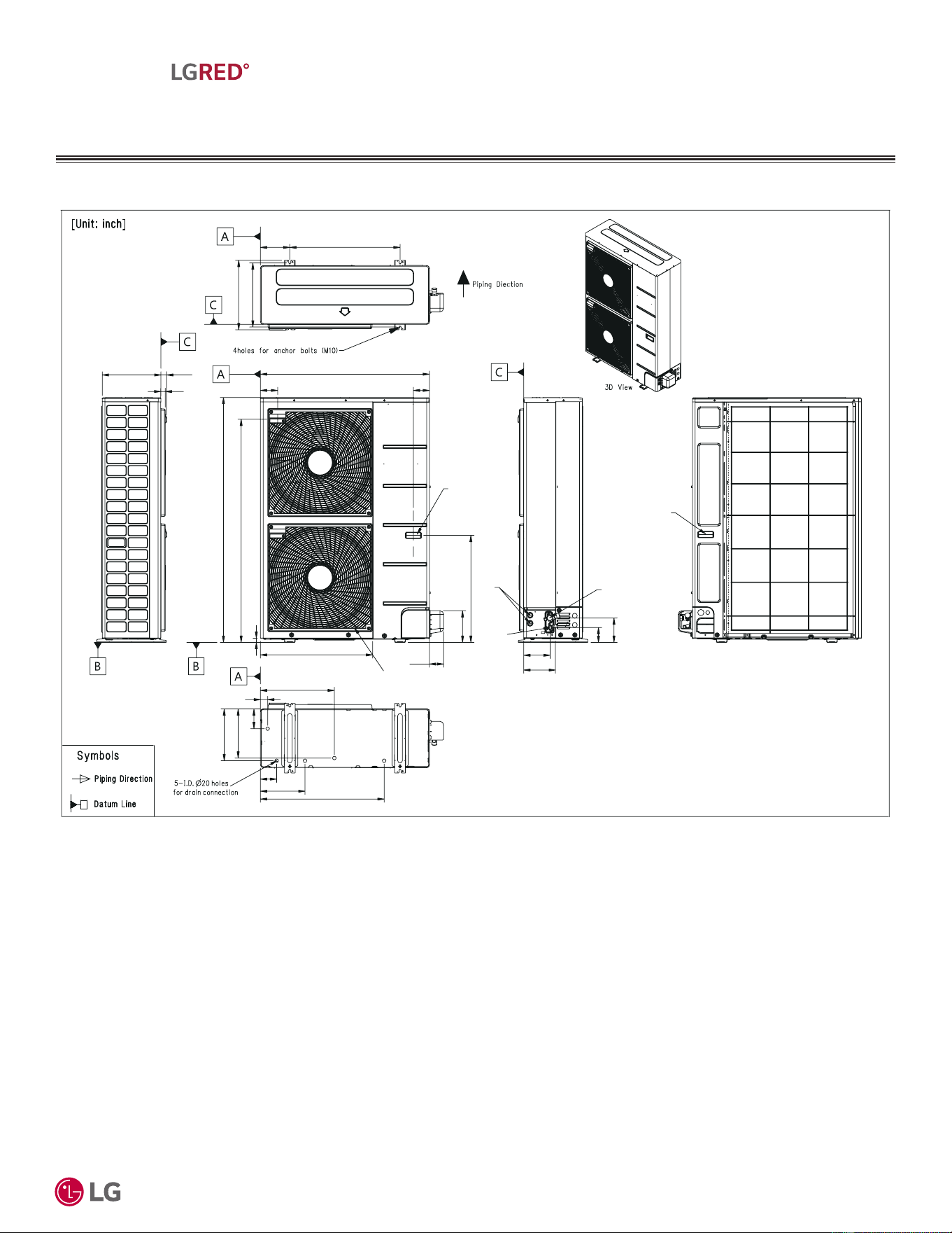
'XHWRRXUSROLF\RIFRQWLQXRXVSURGXFWLQQRYDWLRQVRPHVSHFL¿FDWLRQVPD\FKDQJHZLWKRXWQRWL¿FDWLRQ
©
/*(OHFWURQLFV86$,QF(QJOHZRRG&OLIIV1-$OOULJKWVUHVHUYHG³/*´LVDUHJLVWHUHGWUDGHPDUNRI/*&RUS
37
R32 Multi F MAX with LGRED° Outdoor Unit Product Data
MULTI
F
MAX
MULTI
F
WITH
MULTI F MAX WITH LGRED°
OUTDOOR UNIT
'LPHQVLRQV
Figure 14: KUMXA361A, KUMXA421A, and KUMXA481A Dimensions.
Chassis code : U60A-B
54ïï»
49ñ»
13
ñï»
(1»๛)
ï»๛
3ïñ»๛
37ïñ»
3ïເ»
24ïñ»๛
(3»)
(6ñï»)
23ðເ»
15ïï»
14ñ»๛
6ï» 24ïñ»
11ï»
10ເ»
4ñ»
1»๛
16ñ»
3ï»
9ðເ»
27ïñ»
5ïñ»๛
7
5ñï»
3»
1. Unit must be installed in compliance with the installation manual.
2. Unit must be grounded in accordance with the local or state
regulations and applicable national codes.
3. All field-supplied electrical components and materials must comply
with local, state, and national codes.
4. Electrical characteristics must be considered for electrical
work and design. The capacity of power cable and circuit
breaker for the outdoor unit must follow local, state, national,
and manufacturer requirements.
Notes:
Handle
Liquid Pipe
Connection
(Flare)
Handle
Vapor Pipe
Connection
(Flare)
Power Wiring /
Communication
Cable Access
Holes
Air Outlet
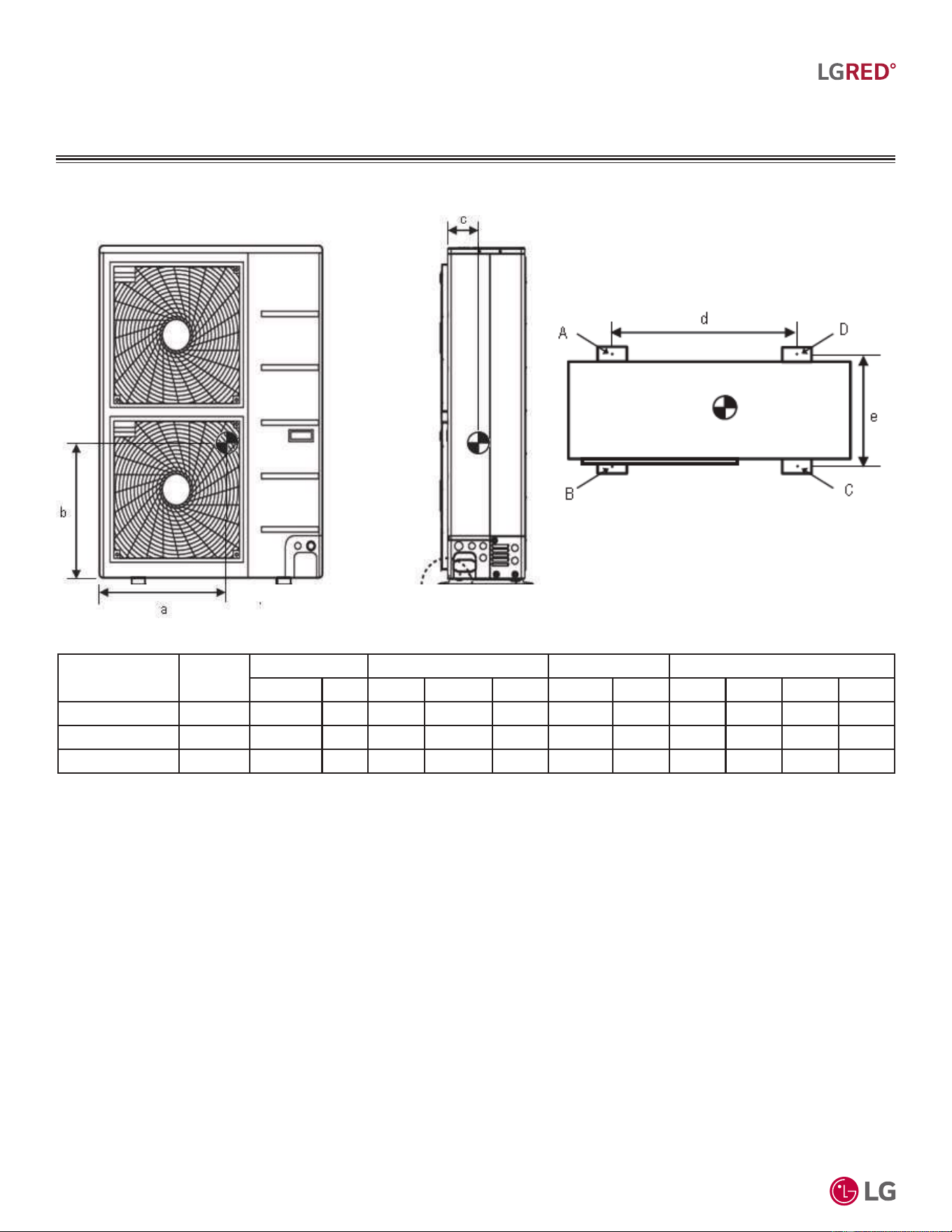
'XHWRRXUSROLF\RIFRQWLQXRXVSURGXFWLQQRYDWLRQVRPHVSHFL¿FDWLRQVPD\FKDQJHZLWKRXWQRWL¿FDWLRQ
©
/*(OHFWURQLFV86$,QF(QJOHZRRG&OLIIV1-$OOULJKWVUHVHUYHG³/*´LVDUHJLVWHUHGWUDGHPDUNRI/*&RUS
38
R32 Multi F and Multi F MAX with LGRED° Outdoor Unit Engineering Manual
MULTI
F
MAX
MULTI
F
WITH
&HQWHURI*UDYLW\&RUQHU:HLJKWV
MULTI F MAX WITH LGRED°
OUTDOOR UNIT
Figure 15: KUMXA361A, KUMXA421A, and KUMXA481A Center of Gravity and Corner Weight Diagram (Appearance may differ than what is depicted
below).
Table 27: KUMXA361A, KUMXA421A, and KUMXA481A Center of Gravity and Corner Weight Dimensions.
Model No. Frame
Weight (lb.) Center of Gravity (in.) Leg (in.) Corner Weight (lb.)
Shipping Net a b c d e A B C D
KUMXA361A U60A-B 239.2 218.3 27-7/32 21-15/32 6-5/8 24-13/32 14-3/16 17.9 20.4 96.0 84.0
KUMXA421A U60A-B 239.2 218.3 27-7/32 21-15/32 6-5/8 24-13/32 14-3/16 17.9 20.4 96.0 84.0
KUMXA481A U60A-B 239.2 218.3 27-7/32 21-15/32 6-5/8 24-13/32 14-3/16 17.9 20.4 96.0 84.0
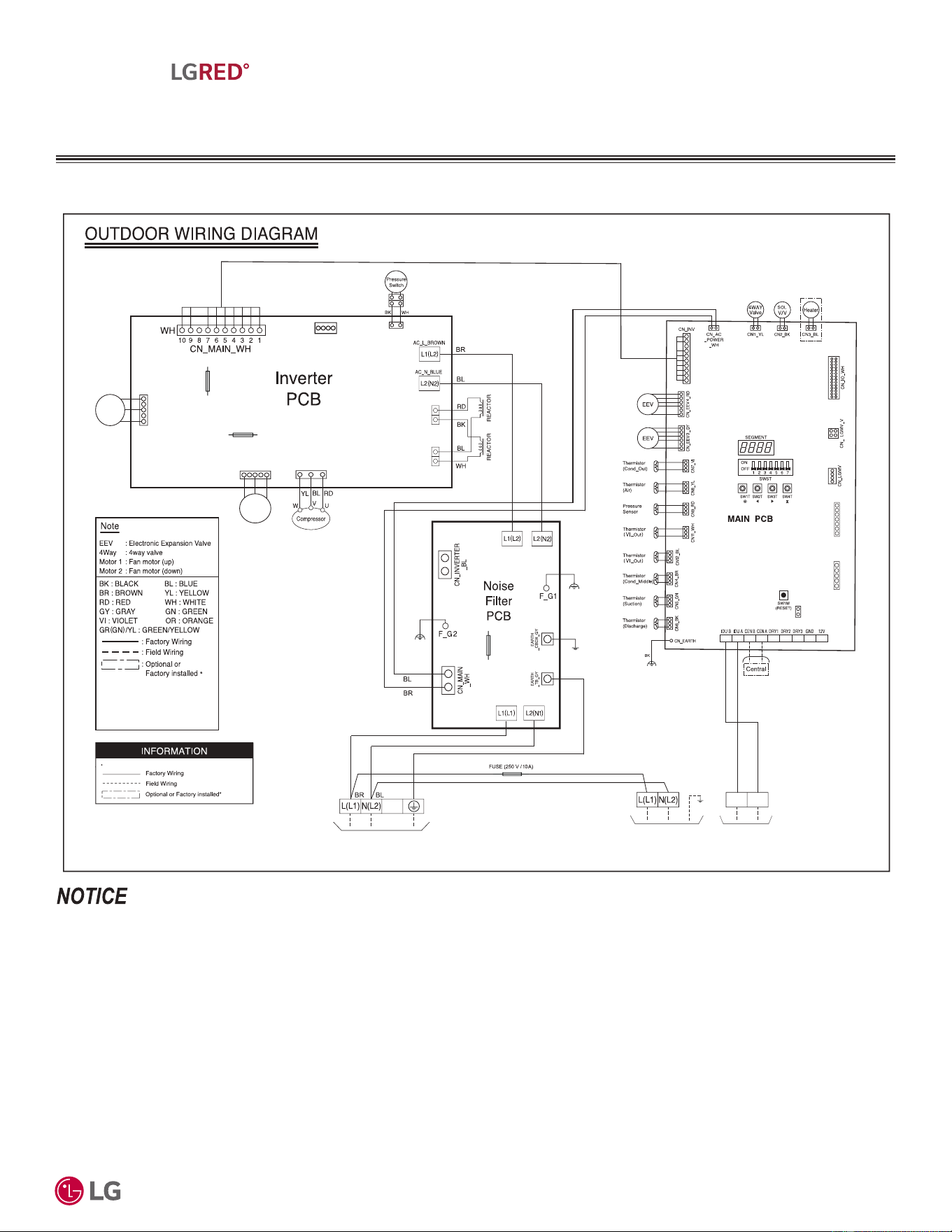
'XHWRRXUSROLF\RIFRQWLQXRXVSURGXFWLQQRYDWLRQVRPHVSHFL¿FDWLRQVPD\FKDQJHZLWKRXWQRWL¿FDWLRQ
©
/*(OHFWURQLFV86$,QF(QJOHZRRG&OLIIV1-$OOULJKWVUHVHUYHG³/*´LVDUHJLVWHUHGWUDGHPDUNRI/*&RUS
39
R32 Multi F MAX with LGRED° Outdoor Unit Product Data
MULTI
F
MAX
MULTI
F
WITH
MULTI F MAX WITH LGRED°
OUTDOOR UNIT
:LULQJ'LDJUDP
Figure 16: KUMXA361A, KUMXA421A, and KUMXA481A Wiring Diagram.
MEZ68866140
MEZ68866140 Rev.01_091924
USE COPPER SUPPLY WIRES.
250V T 3.15A
FUSE_FAN1
Fan
Motor
(up)
250V T 3.15A
FUSE_FAN2
Fan
Motor
(down)
CN_FAN2_BL
CN_FAN1_WH
FUSE
250 V,
45 A
L2_BR N2_BL
CN_PRESS_WH
BL
OR
GN/YL
CN_COMP
REACTOR_RED
REACTOR_BLUE
L1_BR N1_BL
CN_F
CN_AI_WH CN_MB_WH
CN_JIG_PC(WH)
3(A) 4(B)
To Indoor Unit
Communication
To Indoor Unit
Power Supply
Power Supply
* This function can be optional or factory installed
depending on the model.
*Optional parts are sold separately.
Dedicated circuit is field supplied.
10 / 24
.80;$$FDQVXSSRUWXSWRWZREUDQFKGLVWULEXWLRQXQLWVDQGXSWR¿YHLQGRRUXQLWV.80;$$FDQVXSSRUWXSWRWZREUDQFKGLVWULEXWLRQXQLWV
DQGXSWRVL[LQGRRUXQLWV.80;$$FDQVXSSRUWXSWRWZREUDQFKGLVWULEXWLRQXQLWVDQGXSWRHLJKWLQGRRUXQLWV(QVXUHWKHFRPPXQLFDWLRQZLU-
LQJDQGSRZHUZLULQJIURPWKHRXWGRRUXQLWWRWKHLQGRRUXQLWVLVLQVWDOOHGFRUUHFWO\IRUWKHV\VWHPDQGWKHFKRVHQDSSOLFDWLRQ
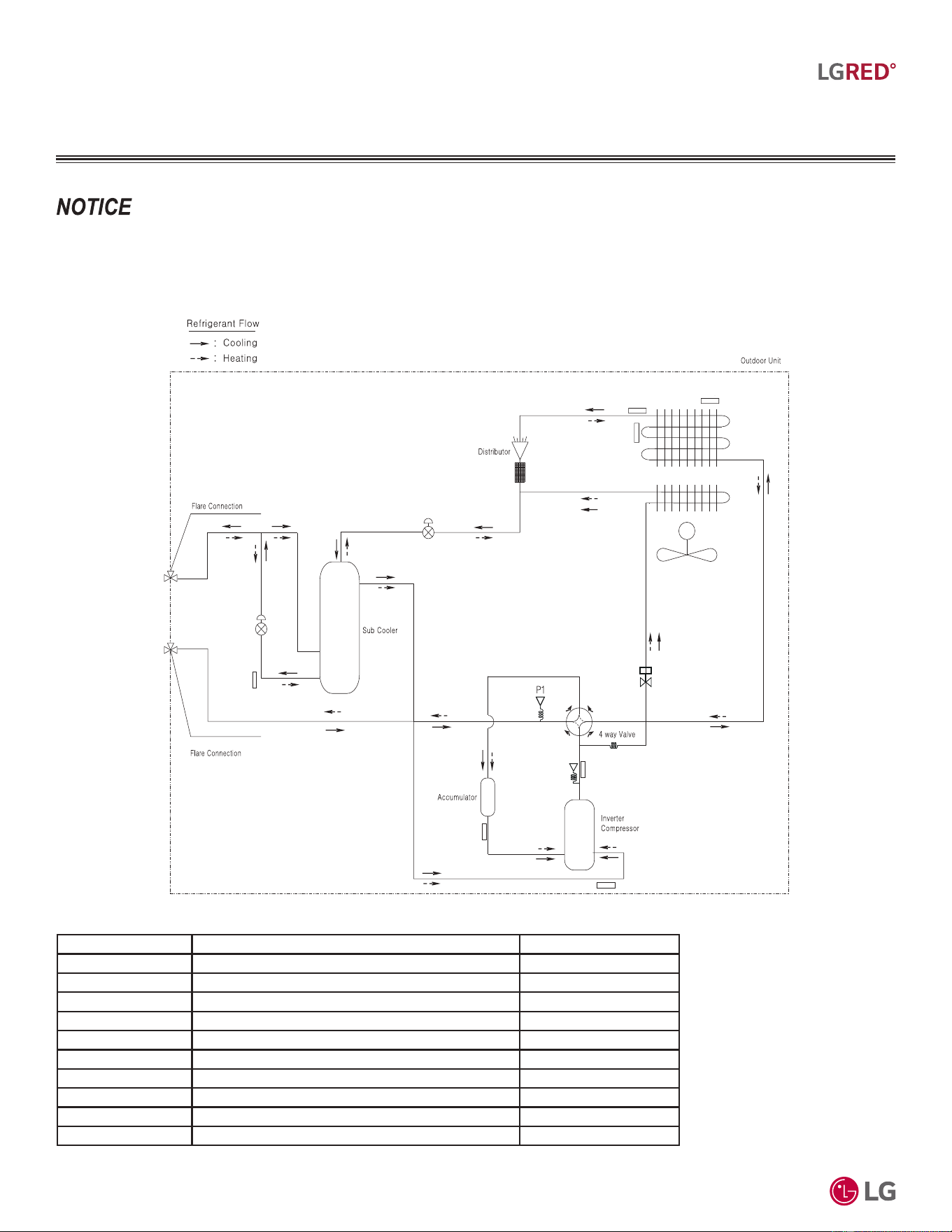
'XHWRRXUSROLF\RIFRQWLQXRXVSURGXFWLQQRYDWLRQVRPHVSHFL¿FDWLRQVPD\FKDQJHZLWKRXWQRWL¿FDWLRQ
©
/*(OHFWURQLFV86$,QF(QJOHZRRG&OLIIV1-$OOULJKWVUHVHUYHG³/*´LVDUHJLVWHUHGWUDGHPDUNRI/*&RUS
40
R32 Multi F and Multi F MAX with LGRED° Outdoor Unit Engineering Manual
MULTI
F
MAX
MULTI
F
WITH
MULTI F MAX WITH LGRED°
OUTDOOR UNIT
5HIULJHUDQW)ORZ'LDJUDP
Figure 17: KUMXA361A, KUMXA421A, and KUMXA481A Refrigerant Flow Diagram.
9DULRXVWRROVDUHDYDLODEOHWRDVVLVWLQSURSHUO\GHVLJQLQJ/*5VSOLWV\VWHPV5HIHUWRWKH³5$SSOLFDWLRQ*XLGH´WKH³6LPSOH&DOFXODWRUIRU&D-
SDFLW\5HIULJHUDQW&KDUJHDQG(63´WKH³/*$LU&RQGLWLRQHU7HFKQLFDO6ROXWLRQV´/$76VRIWZDUHSURJUDPDQGWKHORFDO/*6DOHV5HSUHVHQWDWLYH
M
Th1
Th2
Th3
Th5
Th4
EEV
VI EEV
Th7
Th6
Pressure
Switch
Hotgas Valve
Unit: Inch (mm)
Ø3/8 (9.52)
Ø3/4 (19.05)
Table 28: KUMXA361A, KUMXA421A, and KUMXA481A PCB Connection Details.
Location Description PCB Connector
VI EEV Vapor Injection Electronic Expansion Valve CN_EEV7_GY
EEV Main Electronic Expansion Valve CN_EEV_MAIN_VI
Th1 Suction Pipe Temperature Thermistor CN_SUCTION_GN
Th2 Vapor Injection Out Temperature Thermistor CN_VI_OUT_BL
Th3 Discharge Pipe Temperature Thermistor CN_DISCHA_BK
Th4 Condenser Out Pipe Temperature Thermistor CN_C_PIPE_VI
Th5 Air Temperature Thermistor CN_AIR_YL
Th6 Condenser Middle Pipe Temperature Thermistor CN_MID_BR
Th7 Vapor Injection In Temperature Thermistor CN_VI_IN_WH
P1 Pressure Sensor CN_H_PRESS_RD
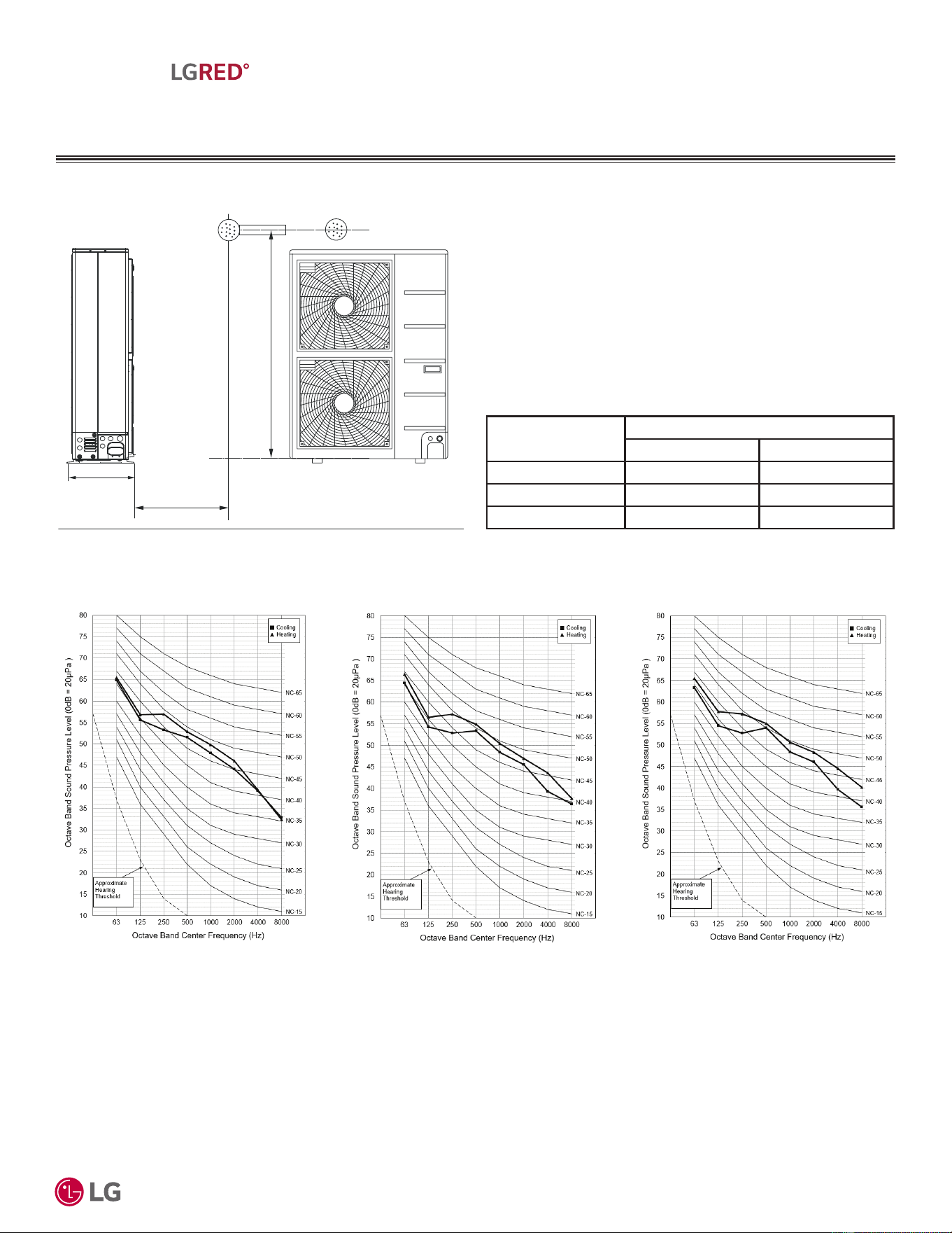
'XHWRRXUSROLF\RIFRQWLQXRXVSURGXFWLQQRYDWLRQVRPHVSHFL¿FDWLRQVPD\FKDQJHZLWKRXWQRWL¿FDWLRQ
©
/*(OHFWURQLFV86$,QF(QJOHZRRG&OLIIV1-$OOULJKWVUHVHUYHG³/*´LVDUHJLVWHUHGWUDGHPDUNRI/*&RUS
41
R32 Multi F MAX with LGRED° Outdoor Unit Product Data
MULTI
F
MAX
MULTI
F
WITH
MULTI F MAX WITH LGRED°
OUTDOOR UNIT
$FRXVWLF'DWD
Figure 18: Acoustic Measurement Location.
Sound Pressure Levels
• 0HDVXUHPHQWWDNHQƍDERYHILQLVKHGIORRUDQGDWDGLVWDQFHRI
ƍIURPIDFHRIIDQGLVFKDUJH
• Measurements taken with no attenuation and units operating at full
load normal operating condition.
• Sound level will vary depending on a range of factors such as
construction (acoustic absorption coefficient) of particular area in
which the equipment is installed.
• Sound pressure levels are measured in dB(A) ±3.
• Tested in anechoic chamber per ISO Standard 3745.
Model No.
Sound Pressure Levels (dB[A])
Cooling (High) Heating (High)
KUMXA361A 53 55
KUMXA421A 54 56
KUMXA481A 54 56
Table 29: Sound Pressure Levels (dB[A]).
Figure 19: Sound Pressure Level Diagrams.
KUMXA361A KUMXA421A KUMXA481A
3.3'
4.92'
Side View
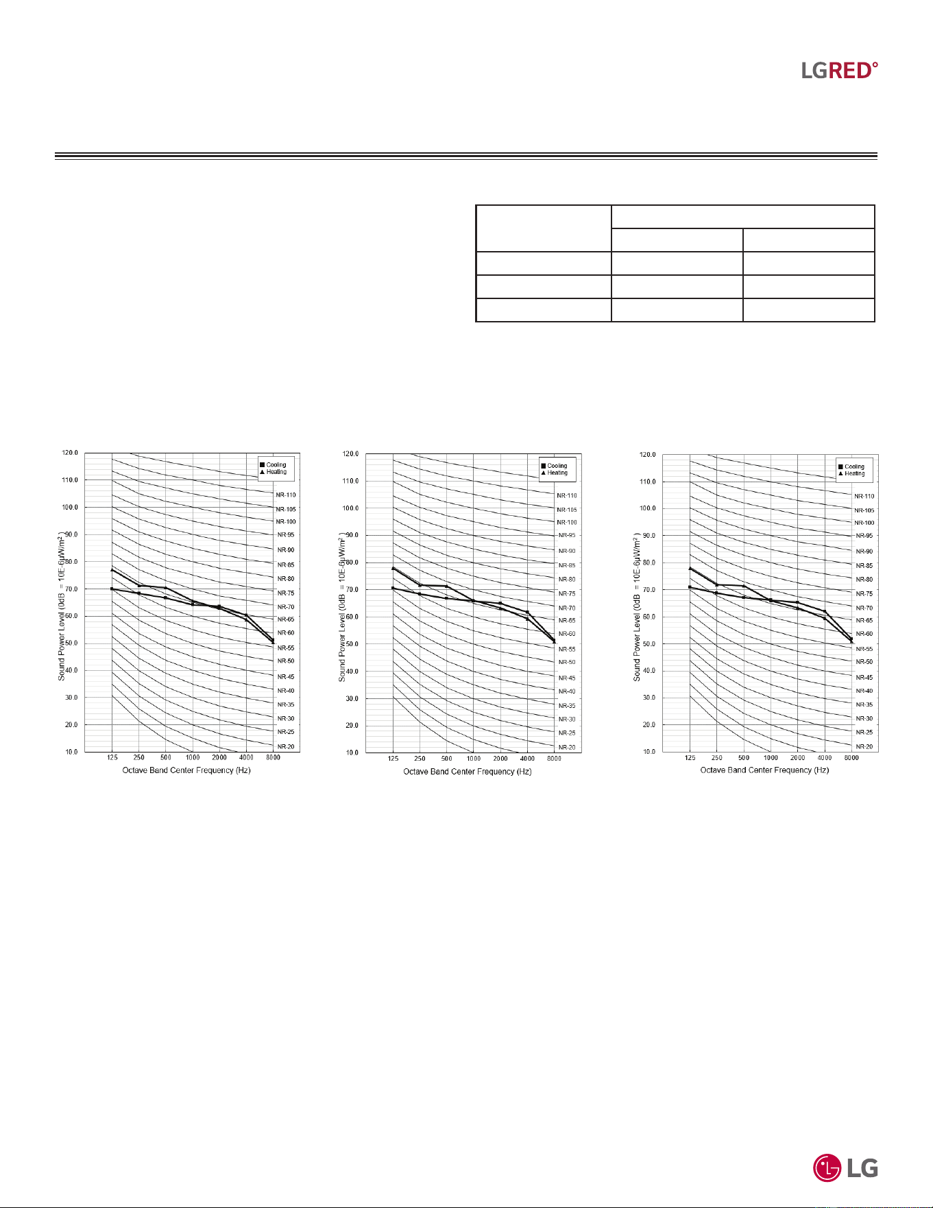
'XHWRRXUSROLF\RIFRQWLQXRXVSURGXFWLQQRYDWLRQVRPHVSHFL¿FDWLRQVPD\FKDQJHZLWKRXWQRWL¿FDWLRQ
©
/*(OHFWURQLFV86$,QF(QJOHZRRG&OLIIV1-$OOULJKWVUHVHUYHG³/*´LVDUHJLVWHUHGWUDGHPDUNRI/*&RUS
42
R32 Multi F and Multi F MAX with LGRED° Outdoor Unit Engineering Manual
MULTI
F
MAX
MULTI
F
WITH
MULTI F MAX WITH LGRED°
OUTDOOR UNIT
$FRXVWLF'DWD
Sound Power Levels
• Data is valid under diffuse field conditions.
• Data is valid under nominal operating conditions.
• Sound power level is measured using rated conditions, and tested
in a reverberation room per ISO 3741 standards.
• Sound level will vary depending on a range of factors such as
construction (acoustic absorption coefficient) of particular area in
which the equipment is installed.
• 5HIHUHQFHDFRXVWLFLQWHQVLW\G% (ȝ:P
2
Model No.
Sound Power Levels (dB[A])
Cooling (High) Heating (High)
KUMXA361A 71 72
KUMXA421A 72 73
KUMXA481A 72 73
Table 30: Sound Power Levels (dB[A]).
Figure 20: Sound Power Level Diagrams.
KUMXA361A KUMXA421A KUMXA481A

MULTI F MAX BRANCH
DISTRIBUTION UNIT
PRODUCT DATA
Mechanical Specifications on page 44
General Data on page 45
Dimensions on page 46
Wiring Diagram on page 47
Refrigerant Flow Diagram on page 48
Y-Branch Accessory on page 49
Branch Distribution Unit Orientation on page 50
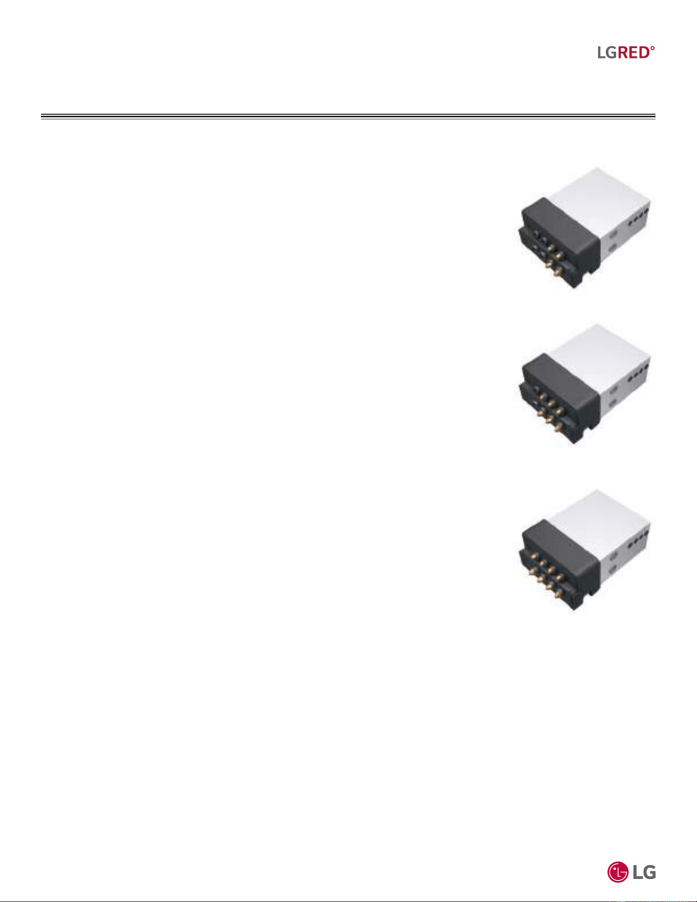
'XHWRRXUSROLF\RIFRQWLQXRXVSURGXFWLQQRYDWLRQVRPHVSHFL¿FDWLRQVPD\FKDQJHZLWKRXWQRWL¿FDWLRQ
©
/*(OHFWURQLFV86$,QF(QJOHZRRG&OLIIV1-$OOULJKWVUHVHUYHG³/*´LVDUHJLVWHUHGWUDGHPDUNRI/*&RUS
44
R32 Multi F and Multi F MAX with LGRED° Outdoor Unit Engineering Manual
MULTI
F
MAX
MULTI
F
WITH
MULTI F MAX BRANCH
DISTRIBUTION UNIT
0HFKDQLFDO6SHFL¿FDWLRQV
Branch Distribution Unit
General
Branch distribution units are designed for use with LG Multi F MAX or LG Multi F MAX with LGRED out-
door units, and are internally piped, wired, assembled and run-tested at the factory. The branch distribu-
tion unit is used as an intermediate refrigerant control device between the outdoor unit and the indoor
units to effectively and efficiently control the heating or cooling operation of the system through the use
of electronic expansion valves.
Refrigerant System
System is designed for use with R32 refrigerant. All refrigerant lines from the outdoor unit to the branch
distribution unit, and from the branch distribution unit to the indoor units, must be field insulated. The
units may be connected to optional field-supplied and field-installed isolation valves for servicing without
evacuating the entire system.
Piping Capabilities
Maximum piping length from the branch distribution unit to the indoor unit is 49.2 equivalent feet. Maxi-
mum elevation difference between branch distribution unit and indoor unit is 32.8 feet. Maximum eleva-
tion difference between two parallel branch distribution units is 49.2 feet.
Electrical
Each branch distribution unit is designed to operate using 208–230/60/1 power with voltage variances of
±10%.
Casing
The casing is designed to mount fully concealed above a finished ceiling, is manufactured of galvanized
steel plate, and is internally
insulated. Branch distribution units do not require a condensate drain.
Port Assembly
Branch distribution units have a two-pipe system consisting of one vapor pipe and one liquid pipe. Units
are available in a choice of two (PMBD3620ZR), three (PMBD3630ZR) or four ports (PMBD3640ZR and
PMBD3641ZR); branch distribution units include two, two-positioned solenoid valves per port. Each port for PMBD3620ZR, PMBD3630ZR,
and PMBD3640ZR units connects to one indoor unit for a maximum nominal capacity of 24,000 Btu/h. For PMBD3641ZR units, ports A, B, C
each connect to one indoor unit for a maximum nominal capacity of 24,000 Btu/h; port D connects to one indoor unit for a nominal capacity
of 24,000 Btu/h to 36,000 Btu/h. Maximum nominal capacity per branch distribution unit is 73,000 Btu/h. Two branch distribution units can be
piped in parallel using accessory Y-branch kit ARBLN03321.
Controls
The unit is provided with factory-installed control boards and an integral microprocessor to communicate with the main control board in the
outdoor unit. Power wiring from the outdoor unit to the branch distribution unit is to be minimum 14 AWG, three-conductor; communication
wiring is to be minimum 18 AWG, two-conductor. All wiring is to be stranded, shielded or unshielded (if shielded, it must be grounded to the
chassis of the outdoor unit only), and must comply with applicable local and national codes.
Figure 21: PMBD3620ZR Two-Port
Branch Distribution Unit.
Figure 22: PMBD3630ZR Three-
Port Branch Distribution Unit.
Figure 23: PMBD3640ZR and
PMBD3641ZR Four-Port Branch
Distribution Unit.
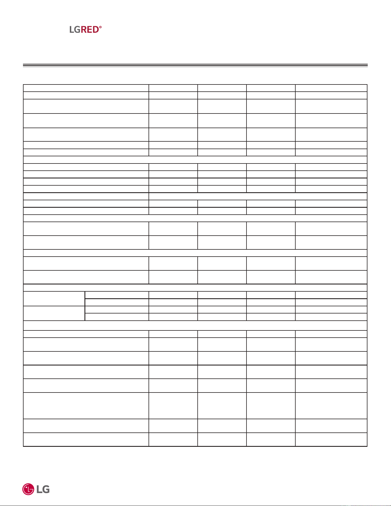
'XHWRRXUSROLF\RIFRQWLQXRXVSURGXFWLQQRYDWLRQVRPHVSHFL¿FDWLRQVPD\FKDQJHZLWKRXWQRWL¿FDWLRQ
©
/*(OHFWURQLFV86$,QF(QJOHZRRG&OLIIV1-$OOULJKWVUHVHUYHG³/*´LVDUHJLVWHUHGWUDGHPDUNRI/*&RUS
45
R32 Multi F MAX Branch Distribution Unit Product Data
MULTI
F
MAX
MULTI
F
WITH
*HQHUDO'DWD
Table 31: Multi F MAX Branch Distribution Unit General Data.
MULTI F MAX BRANCH
DISTRIBUTION UNIT
1
At least one Branch Distribution Unit is required for system operation; a maximum of two can be installed per outdoor unit with use of Y-branch accessory (ARBLN03321) To connect only one (1) indoor unit to a
branch distribution unit, the system must include another branch distribution unit with at least one (1) connected indoor unit.
2Branch Distribution Unit can accommodate from one (1) indoor unit up to four (4) indoor units depending on the ports available.
3
All power wiring / communication wiring is to be stranded, shielded or unshielded (if shielded, it must be grounded to the chassis of the outdoor unit only), and must comply with applicable local and national codes.
4
Piping lengths are equivalent.
Model Number PMBD3620ZR PMBD3630ZR PMBD3640ZR PMBD3641ZR
No. of Connectable Indoor Units
1
1-2 1-3 1-4 1-4
Max. Nominal Capacity / Port (Btu/h)
2
24,000 24,000 24,000
Ports A,B,C : 24,000
Ports D : 36,000
Connected Indoor Unit Capacity (Btu/h) 24,000 24,000 24,000
Ports A,B,C : 24,000
Ports D : 30,000 ~ 36,000
Max. Nominal Capacity / Branch Distribution Unit
(Btu/h)
48,000 72,000 73,000 73,000
Operation Temperature Range (°F DB) 0 ~ 150 0 ~ 150 0 ~ 150 0 ~ 150
Maximum Humidity 80% 80% 80% 80%
8QLW'DWD
Refrigerant Type R32 R32 R32 R32
Power Supply V, Ø, Hz 208-230, 1, 60 208-230, 1, 60 208-230, 1, 60 208-230, 1, 60
Power Input (W) 82 87 97 97
Rated Amps (A) 0.34 0.36 0.4 0.4
Dimensions W x H x D (in.) 17-1/4 x 6-7/16 x 12-1/8
Net Unit Weight (lbs.) 17.4 18.3 19.4 19.6
Shipping Weight (lbs.) 20.9 21.8 22.9 23.4
3RZHU:LULQJ
3
From Outdoor Unit to Branch Distribution Unit
(Qty. x AWG)
3
3C x 14 3C x 14 3C x 14 3C x 14
From Branch Distribution Unit to Indoor Unit
(Qty. x AWG)
3
3C x 14 3C x 14 3C x 14 3C x 14
&RPPXQLFDWLRQV:LULQJ
3
From Outdoor Unit to Branch Distribution Unit
(Qty. x AWG)
3
2C x 18 2C x 18 2C x 18 2C x 18
From Branch Distribution Unit to Indoor Unit
(Qty. x AWG)
3
2C x 18 2C x 18 2C x 18 2C x 18
3LSLQJ&RQQHFWLRQV
Outdoor Unit to Branch
Distribution Unit
Liquid (in., OD) Ø3/8 Braze Ø3/8 Braze Ø3/8 Braze Ø3/8 Braze
Vapor (in., OD) Ø3/4 Braze Ø3/4 Braze Ø3/4 Braze Ø3/4 Braze
Branch Distribution Unit
to Indoor Units
Liquid (in., OD) x Qty. Ø1/4 x 2 Flare Ø1/4 x 3 Flare Ø1/4 x 4 Flare Ø1/4 x 4 Flare
Vapor (in., OD) x Qty. Ø3/8 x 2 Flare Ø3/8 x 3 Flare Ø3/8 x 4 Flare Ø3/8 x 3 Flare; Ø1/2 x 1 Flare
3LSLQJ/HQJWKV
Maximum Total System Piping (ft.)
4
475.7 475.7 475.7 475.7
Maximum Main Pipe Length (Outdoor Unit
to Branch Distribution Units [ft.])
180.4 180.4 180.4 180.4
Total Branch Piping (Branch Distribution Units
to Indoor Units [ft.])
295.3 295.3 295.3 295.3
Maximum Branch Pipe Length Between
Branch Distribution Unit and Each Indoor Unit [ft.])
49.2 49.2 49.2 49.2
Maximum Outdoor Unit to Indoor Unit
Pipe Length (ft.)
229.6 229.6 229.6 229.6
Piping Length (No Additional Refrigerant [ft.];
approx. 16.4 ft. or 49.2 ft. of Main Piping
(depending on ODU model) + 131.2 ft. of Branch
Piping)
147.6 or 180.4
(Depending on
ODU Model)
147.6 or 180.4
(Depending on
ODU Model)
147.6 or 180.4
(Depending on
ODU Model)
147.6 or 180.4
(Depending on
ODU Model)
Maximum Elevation between Branch Distribution
Unit and Indoor Unit (ft.)
32.8 32.8 32.8 32.8
Maximum Elevation between Branch Distribution
Unit and Branch Distribution Unit (ft.)
49.2 49.2 49.2 49.2
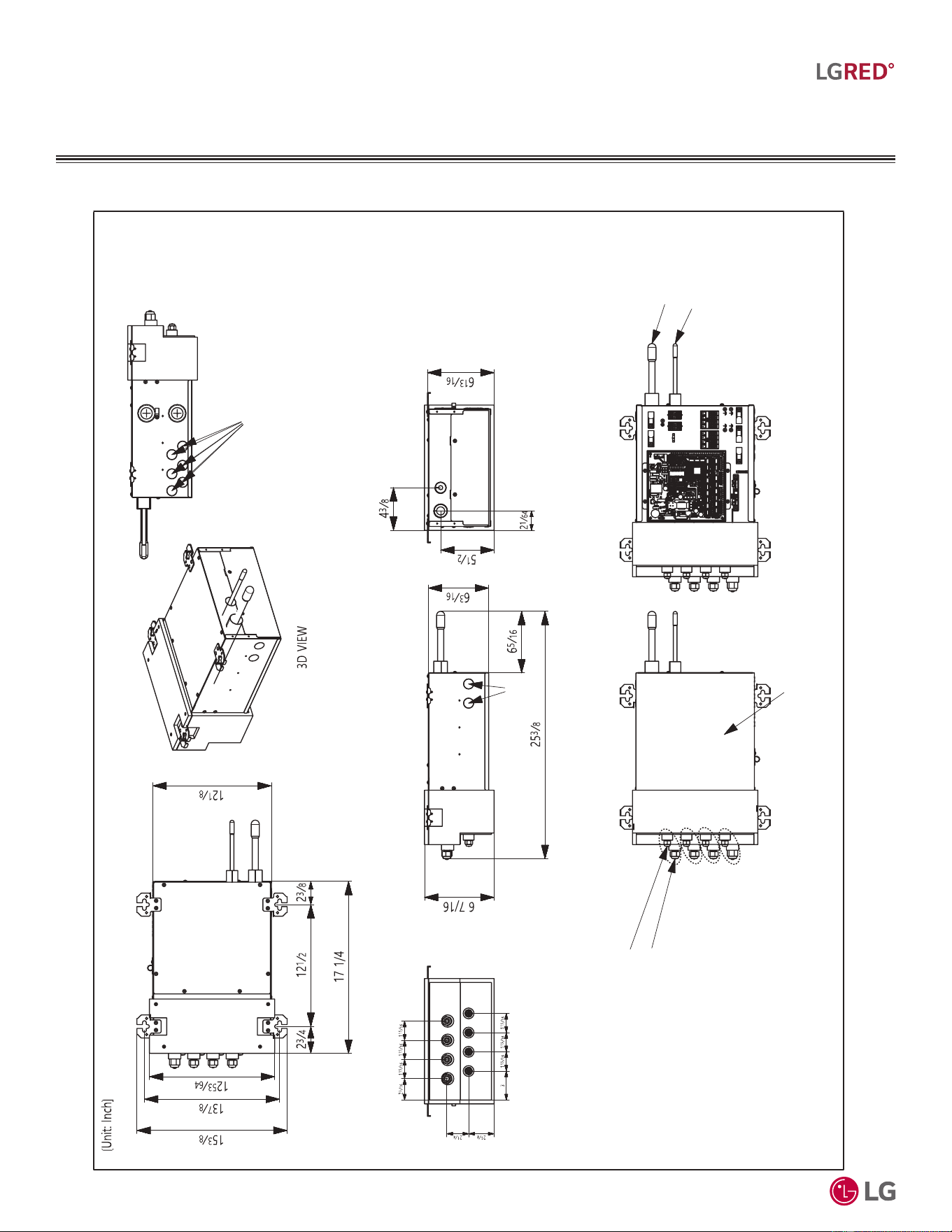
'XHWRRXUSROLF\RIFRQWLQXRXVSURGXFWLQQRYDWLRQVRPHVSHFL¿FDWLRQVPD\FKDQJHZLWKRXWQRWL¿FDWLRQ
©
/*(OHFWURQLFV86$,QF(QJOHZRRG&OLIIV1-$OOULJKWVUHVHUYHG³/*´LVDUHJLVWHUHGWUDGHPDUNRI/*&RUS
46
R32 Multi F and Multi F MAX with LGRED° Outdoor Unit Engineering Manual
MULTI
F
MAX
MULTI
F
WITH
Figure 24: PMBD3620ZR, PMBD3630ZR, PMBD3640ZR, and PMBD3641ZR Dimensions.
'LPHQVLRQV
MULTI F MAX BRANCH
DISTRIBUTION UNIT
Notes:
1. For PMBD3620ZR Unit, Ports A and B are Available.
2. For PMBD3630ZR Unit, Ports A, B, and C are Available.
3. For PMBD3640ZR and PMBD3641ZR Units, Ports A, B, C, and D are Available.
A-C
Connections:
Liquid Pipe Ø1/4
Vapor Pipe Ø3/8
PMBD3640ZR1
and PMBD3641ZR1 D
Connections:
Liquid Pipe Ø1/4
Vapor Pipe Ø1/2
Indoor Unit Liquid Piping
Connection (Flare)
Indoor Unit Vapor Piping
Connection (Flare)
Control Cover
Outdoor Unit
Vapor Piping
Connection (Braze)
Outdoor Unit
Liquid Piping
Connection (Braze)
Power Wiring and Communication
Wiring Routing Holes
Power Wiring and Communication
Wiring Routing Holes
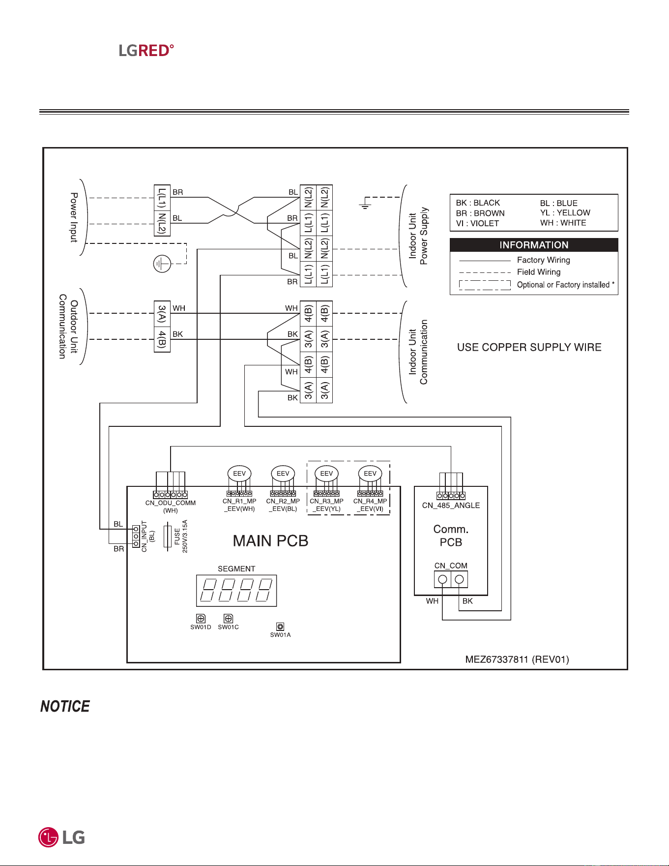
'XHWRRXUSROLF\RIFRQWLQXRXVSURGXFWLQQRYDWLRQVRPHVSHFL¿FDWLRQVPD\FKDQJHZLWKRXWQRWL¿FDWLRQ
©
/*(OHFWURQLFV86$,QF(QJOHZRRG&OLIIV1-$OOULJKWVUHVHUYHG³/*´LVDUHJLVWHUHGWUDGHPDUNRI/*&RUS
47
R32 Multi F MAX Branch Distribution Unit Product Data
MULTI
F
MAX
MULTI
F
WITH
:LULQJ'LDJUDP
Figure 25: PMBD3620ZR, PMBD3630ZR, PMBD3640ZR, and PMBD3641ZR Wiring Diagram.
MULTI F MAX BRANCH
DISTRIBUTION UNIT
• 30%'=5%UDQFK'LVWULEXWLRQ8QLWVXSSOLHGZLWK$%RUWZRLQGRRUXQLWSRZHUVXSSO\WHUPLQDOVDQGFRPPXQLFDWLRQWHUPLQDOVHDFK
• 30%'=5%UDQFK'LVWULEXWLRQ8QLWVXSSOLHGZLWK$%&RUWKUHHLQGRRUXQLWSRZHUVXSSO\WHUPLQDOVDQGFRPPXQLFDWLRQWHUPLQDOV
each.
• 30%'=5DQG30%'=5%UDQFK'LVWULEXWLRQ8QLWVVXSSOLHGZLWK$%&'RUIRXULQGRRUXQLWSRZHUVXSSO\WHUPLQDOVDQGFRP-
PXQLFDWLRQWHUPLQDOVHDFK
Connect the indoor unit power supply wiring and communications
wiring depending on the number installed.
10 / 24
*Function is optional or factory
installed depending on the model.
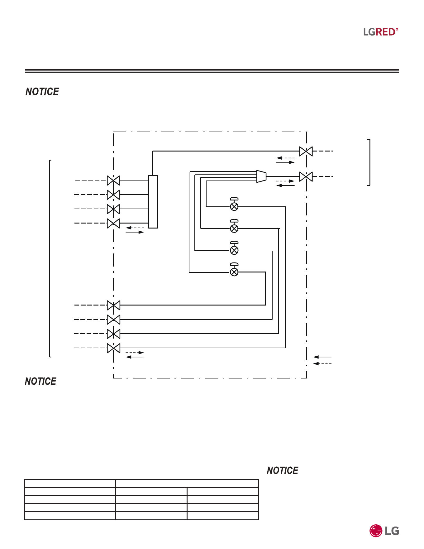
'XHWRRXUSROLF\RIFRQWLQXRXVSURGXFWLQQRYDWLRQVRPHVSHFL¿FDWLRQVPD\FKDQJHZLWKRXWQRWL¿FDWLRQ
©
/*(OHFWURQLFV86$,QF(QJOHZRRG&OLIIV1-$OOULJKWVUHVHUYHG³/*´LVDUHJLVWHUHGWUDGHPDUNRI/*&RUS
48
R32 Multi F and Multi F MAX with LGRED° Outdoor Unit Engineering Manual
MULTI
F
MAX
MULTI
F
WITH
5HIULJHUDQW)ORZ'LDJUDP
Figure 26: PMBD3620ZR, PMBD3630ZR, PMBD3640ZR, and PMBD3641ZR Refrigerant Flow Diagram.
1. %UD]HGFRQQHFWLRQVIRURXWGRRUXQLWWREUDQFKGLVWULEXWLRQXQLWIRU¿HOGSLSLQJLQVWDOODWLRQ
2. )ODUHGFRQQHFWLRQVIRUEUDQFKGLVWULEXWLRQXQLWWRLQGRRUXQLWIRU¿HOGSLSLQJLQVWDOODWLRQ
3. 0DWFKWKHEUDQFKGLVWULEXWLRQSRUWVWRWKHLQGRRUXQLWDQGRXWGRRUXQLWSLSLQJVL]HV8VHDQDGDSWHULIWKHSLSLQJVL]HGRHVQRWPDWFKWKHSLSLQJ
VL]HRIWKHFRQQHFWLQJLQGRRUXQLW
4. ((9(OHFWURQLF([SDQVLRQ9DOYH
5. 30%'=5%UDQFK'LVWULEXWLRQ8QLWVXSSOLHGZLWK³$%´RUWZRLQGRRUXQLWSRZHUVXSSO\WHUPLQDOVDQGFRPPXQLFDWLRQWHUPLQDOVHDFK
30%'=5%UDQFK'LVWULEXWLRQ8QLWVXSSOLHGZLWK³$%&´RUWKUHHLQGRRUXQLWSRZHUVXSSO\WHUPLQDOVDQGFRPPXQLFDWLRQWHUPLQDOVHDFK
30%'=5DQG30%'=5%UDQFK'LVWULEXWLRQ8QLWVVXSSOLHGZLWK³$%&'´RUIRXULQGRRUXQLWSRZHUVXSSO\WHUPLQDOVDQG
FRPPXQLFDWLRQWHUPLQDOVHDFK
9DULRXVWRROVDUHDYDLODEOHWRDVVLVWLQSURSHUO\GHVLJQLQJ/*5VSOLWV\VWHPV5HIHUWRWKH³5$SSOLFDWLRQ*XLGH´WKH³6LPSOH&DOFXODWRUIRU&D-
SDFLW\5HIULJHUDQW&KDUJHDQG(63´WKH³/*$LU&RQGLWLRQHU7HFKQLFDO6ROXWLRQV´/$76VRIWZDUHSURJUDPDQGWKHORFDO/*6DOHV5HSUHVHQWDWLYH
MULTI F MAX BRANCH
DISTRIBUTION UNIT
Main Liquid
Piping
Main Vapor
Piping
(3/4
"
[19.05mm])
(3/8
"
[9.52mm])
* PMBD3641ZR
Unit: Inch (mm)
Refrigerant flow
Cooling
Heating
EEV-A
EEV-B
EEV-C
EEV-D
To
Outdoor
Unit
To
1/2" (12.7mm)
D Vapor
(3/8" [9.52mm])
C Vapor
(3/8" [9.52mm])
B Vapor
(3/8" [9.52mm])
A Vapor
(3/8" [9.52mm])
D Liquid
(1/4" [6.35mm])
C Liquid
(1/4" [6.35mm])
B Liquid
(1/4" [6.35mm])
A Liquid
(1/4" [6.35mm])
Indoor
Unit
D Vapor
Indoor Unit Capacity (kBtu/h) Refrigerant Connections Pipe Size (Unit: Inch [mm])
7, 9 Ø1/4 (6.35) Ø3/8 (9.52)
12, 15 Ø1/4 (6.35) Ø3/8 (9.52)
18, 24 Ø1/4 (6.35) Ø1/2 (12.7)
30, 36 Ø3/8 (9.52) Ø5/8 (15.88)
30%'=5%UDQFK'LVWULEXWLRQLQFOXGHVDGDSWHU
DFFHVVRU\
ĺ[(D
ĺ[(D
Table 32: Indoor Unit Connection Pipe Sizes.
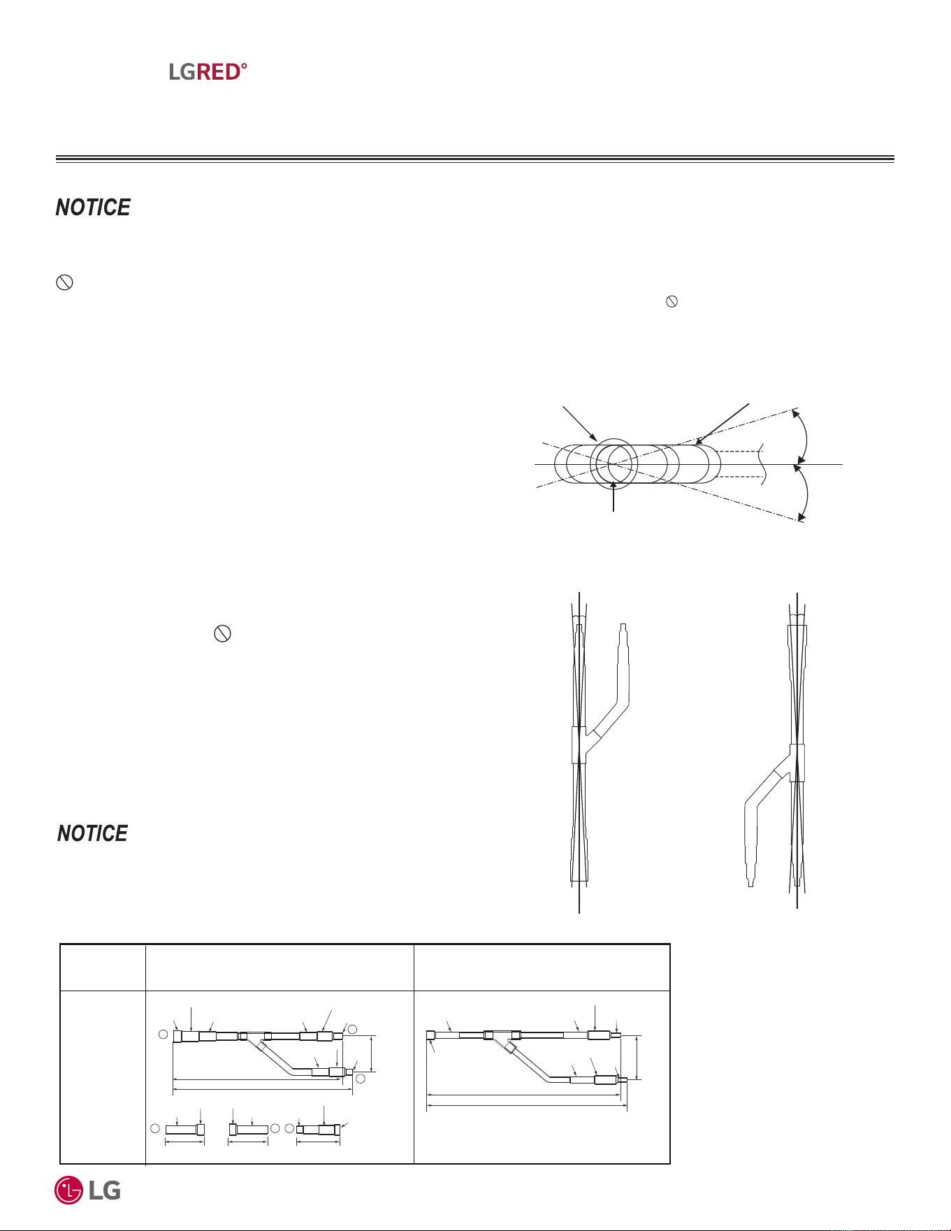
'XHWRRXUSROLF\RIFRQWLQXRXVSURGXFWLQQRYDWLRQVRPHVSHFL¿FDWLRQVPD\FKDQJHZLWKRXWQRWL¿FDWLRQ
©
/*(OHFWURQLFV86$,QF(QJOHZRRG&OLIIV1-$OOULJKWVUHVHUYHG³/*´LVDUHJLVWHUHGWUDGHPDUNRI/*&RUS
49
R32 Multi F MAX Branch Distribution Unit Product Data
MULTI
F
MAX
MULTI
F
WITH
<%UDQFK.LW
0XOWL)0$;0XOWL)0$;ZLWK
LGRED Y-Branch Kits
LG-suppled Y-branch kit ARBLN03321 MUST be used when install-
ing two (2) branch distribution units in parallel on one (1) Multi F
MAX / Multi F MAX with LGRED system. Each Y-branch kit includes
two (2) Y-branches (one for the liquid line and one for the vapor line)
and insulation covers.
Y-branches may be installed in horizontal or vertical configurations.
When installed horizontally, the straight-through leg must be within
±5° rotation. When installed vertically, the straight-through leg must
be within ±3° of plumb.
Y-branches must be properly installed following instructions in the
applicable LG manual. Y-branches must always be installed with the
single port facing the outdoor unit and the two-port end facing the
branch distribution units. Do not install Y-branches backwards
as refrigerant flow cannot make U-turns. The Y-branch kit must
be located at least three (3) feet from the outdoor unit. Provide a
minimum of 20 inches between a Y-branch and the branch distribu-
tion unit.
It is recommended that when a Y-branch is located in a pipe chase
or other concealed space, access doors must be provided for
inspection access.
7KHHTXLYDOHQWSLSHOHQJWKRIHDFK<EUDQFKƍPXVWEHDGGHGWR
the main pipe segment entered into LATS piping design software.
No Substitutions on Piping Components
Only LG supplied Y-branch can be used to join one pipe segment to two or more segments.
7KLUGSDUW\RU¿HOGIDEULFDWHG
FRPSRQHQWVVXFKDVWHHV<¿WWLQJVFRXSOLQJVRURWKHUEUDQFK¿WWLQJVDUHQRWSHUPLWWHG7KHRQO\¿HOGSURYLGHG¿WWLQJVDO-
ORZHGLQD0XOWL)0$;0XOWL)0$;ZLWK/*5('SLSLQJV\VWHPDUHDQGORQJUDGLXVHOERZVDQGIXOOSRUWEDOOYDOYHVLI
applicable).
9HUWLFDO83&RQ¿JXUDWLRQ
ELEVATION VIEW
9HUWLFDO'2:1&RQ¿JXUDWLRQ
Figure 27: <%UDQFK+RUL]RQWDO&RQ¿JXUDWLRQ
+5°
Horizontal
Plane
-5°
Branch Leg
Straight-through Leg
ELEVATION VIEW
Y-branch Inlet
-3° of Plumb +3° of Plumb
-3° of Plumb +3° of Plumb
Figure 28: <%UDQFK9HUWLFDO&RQ¿JXUDWLRQV
Kit Model
No.
Vapor Pipe Dimensions
Unit: Inch
ARBLN03321
16-1/4 (413)
15-3/8 (390)
I.D. 3/4 (19.05)
I.D. 3/4 (19.05)
I.D. 3/4 (19.05)
I.D. 1/2 (12.7)
I.D. 1/2
(12.7)
2-3/4 (70)
I.D. 5/8 (15.88)
I.D. 5/8 (15.88)
I.D. 1 (25.4)
I.D. 1 (25.4)
O.D. 1 (25.4)
3-1/8 (80)
4-5/16 (110)
3-1/4
(83)
1
2
3
3
O.D. 3/4 (19.05)
O.D. 3/4 (19.05)
1 2
I.D. 7/8 (22.2)
I.D. 7/8 (22.2)
I.D. 7/8 (22.2)
I.D. 28.58 (1-1/8)
I.D. 1/2 (12.7)
I.D. 1/2 (12.7)
I.D. 1/2 (12.7)
(74)
2-15/16
13-1/16 (332)
12-5/8 (321)
I.D. 1/4 (6.35)
I.D. 1/4 (6.35)
I.D. 3/8 (9.52)
I.D. 3/8 (9.52)
I.D. 3/8 (9.52)
Liquid Pipe Dimensions
AJR54072930
AJR54072928
Figure 29: Indoor Unit Y-Branch Dimensions.
• 'HVLJQSUHVVXUHLVSVLJ
• $OOGLPHQVLRQVLQLQFKHV7ROHUDQFHLQFK
• ,PDJHVDUHQRWWRVFDOH
9DULRXVWRROVDUHDYDLODEOHWRDVVLVWLQSURSHUO\GHVLJQLQJ/*5VSOLWV\VWHPV5HIHUWRWKH³5$SSOLFDWLRQ*XLGH´WKH³6LPSOH&DOFXODWRUIRU&D-
SDFLW\5HIULJHUDQW&KDUJHDQG(63´WKH³/*$LU&RQGLWLRQHU7HFKQLFDO6ROXWLRQV´/$76VRIWZDUHSURJUDPDQGWKHORFDO/*6DOHV5HSUHVHQWDWLYH
MULTI F MAX BRANCH
DISTRIBUTION UNIT
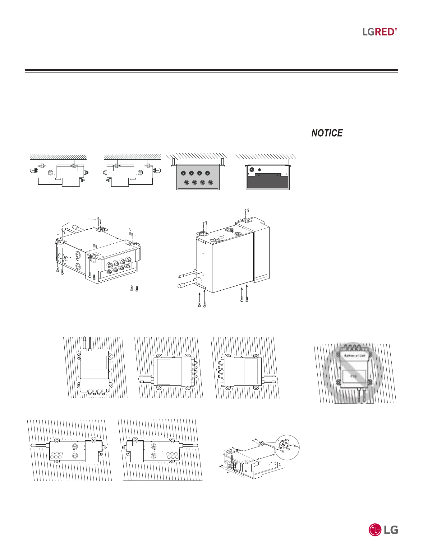
'XHWRRXUSROLF\RIFRQWLQXRXVSURGXFWLQQRYDWLRQVRPHVSHFL¿FDWLRQVPD\FKDQJHZLWKRXWQRWL¿FDWLRQ
©
/*(OHFWURQLFV86$,QF(QJOHZRRG&OLIIV1-$OOULJKWVUHVHUYHG³/*´LVDUHJLVWHUHGWUDGHPDUNRI/*&RUS
50
R32 Multi F and Multi F MAX with LGRED° Outdoor Unit Engineering Manual
MULTI
F
MAX
MULTI
F
WITH
%UDQFK'LVWULEXWLRQ8QLW2ULHQWDWLRQ
Multi F MAX branch distribution (BD) units can be installed in a multitude of options to fit various building configurations and job or applica-
tion requirements. Multi F MAX branch distribution units include electronic expansion valves that properly seat only if the branch distribution
unit is installed in an acceptable orientation. Installations with improper branch distribution unit orientation risk incomplete valve seating and
system performance degradation from potential refrigerant leakage through the electronic expansion valve.
7KLVPDWHULDOLVIRULQIRUPDWLRQDO
RUHGXFDWLRQDOSXUSRVHVRQO\,WLV
QRWLQWHQGHGWREHDVXEVWLWXWHIRU
SURIHVVLRQDODGYLFH&RQVXOWZLWK
\RXUHQJLQHHURUGHVLJQSURIHV-
VLRQDOVIRUVSHFL¿FDSSOLFDWLRQVWR
\RXUV\VWHP
Figure 30: Acceptable Branch Distribution Unit Ceiling Mount Orientations.
Figure 31: Acceptable Branch Distribution Unit Wall Mount Orientations.
Figure 32: Unacceptable Branch
Distribution Unit Orientation.
Branch Distribution Unit Orientation
Left Side View,
Port End Facing Left
Ceiling Mounting Options
Port End View
Right Side View,
Port End Facing Right
Ceiling Ceiling
Ceiling
Top of Unit
Refrigerant Piping End View
Ceiling
Top of Unit
Top of Unit
Top of Unit
Top of Unit
Into the Unit
Into the Unit
Into the Ceiling
Isometric View
Into the Unit
Into the Ceiling
Into the Ceiling
Into the Unit
Into the Unit
Through the Hangar
Into the Ceiling
Through the Hangar
Into the Ceiling
Side View
Side of Unit
MULTI F MAX BRANCH
DISTRIBUTION UNIT
Wall
Bottom View, Port End Facing Up
Bottom of Unit
PCB
Wall
Bottom View, Port End Down
Wall Wall
Bottom View, Port End Facing Right Bottom View, Port End Facing Left
Wall
Left Side View, Port End Facing Left
Wall
Right Side View, Port End Facing Right
Bottom of Unit
Bottom of Unit
Bottom of Unit
PCB
PCB
PCB
Top of Unit Top of UnitTop of Unit Top of Unit
Screws (M5)
(Field supplied)
Into the
Wall
Into the Unit
Into the Unit
Into the Wall
Bottom of Unit
Isometric View

ELECTRICAL
CONNECTIONS
General Guidelines on page 52
Wiring Specifications on page 53
Systems for Multi F with LGRED on page 55
Systems for Multi F MAX with LGRED on page 56
,QGRRU8QLWV&RQWUROOHUVRQSDJH
'XHWRRXUSROLF\RIFRQWLQXRXVSURGXFWLQQRYDWLRQVRPHVSHFL¿FDWLRQVPD\FKDQJHZLWKRXWQRWL¿FDWLRQ
©
/*(OHFWURQLFV86$,QF(QJOHZRRG&OLIIV1-$OOULJKWVUHVHUYHG³/*´LVDUHJLVWHUHGWUDGHPDUNRI/*&RUS
52
R32 Multi F and Multi F MAX with LGRED° Outdoor Unit Engineering Manual
MULTI
F
MAX
MULTI
F
WITH
ELECTRICAL CONNECTIONS
*HQHUDO*XLGHOLQHV
• $OOSRZHUOLQHYROWDJHZLULQJDQGFRPPXQLFDWLRQFDEOHLQVWDOODWLRQPXVWEHSHUIRUPHGE\WUDLQHGVHUYLFHSURYLGHUVZRUNLQJLQDFFRUGDQFH
ZLWKORFDOVWDWHDQG1DWLRQDO(OHFWULFDO&RGH1(&8/IHGHUDOUHJXODWLRQVUHODWHGWRHOHFWULFDOHTXLSPHQWDQGZLULQJDQGIROORZLQJWKH
PDQXIDFWXUHUSURGXFWGLDJUDPVUHTXLUHPHQWVDQGLQVWUXFWLRQVLQWKLVPDQXDO(OHFWULFVKRFNFDQFDXVHSK\VLFDOLQMXU\RUGHDWK
• %HVXUHWKDWPDLQSRZHUWRWKHXQLWLVFRPSOHWHO\RIIEHIRUHLQVWDOOLQJ)ROORZDOOVDIHW\DQGZDUQLQJLQIRUPDWLRQ)DLOXUHWRGRVRZLOOFDXVH
HOHFWULFVKRFNUHVXOWLQJLQERGLO\LQMXU\RUGHDWK
• ,QVWDOODPDLQVKXWRIIVZLWFKRUFLUFXLWEUHDNHUWKDWLQWHUUXSWVDOOSRZHUVRXUFHVVLPXOWDQHRXVO\FLUFXLWEUHDNHUPXVWEHUHVLVWDQWWRHOHF-
WURPDJQHWLFFXUUHQWV%HVXUHWKDWWKHFLUFXLWEUHDNHURUVRPHRWKHUHPHUJHQF\SRZHUFXWRIIGHYLFHLVLQSODFHEHIRUHDQ\SRZHUZLULQJLV
GRQHWRWKHV\VWHP)DLOXUHWRGRVRZLOOFDXVHERGLO\LQMXU\RUGHDWK
• 1HYHUWRXFKDQ\SRZHUOLQHVRUOLYHFDEOHVEHIRUHDOOSRZHULVFXWRIIWRWKHV\VWHP7RGRVRZLOOFDXVHERGLO\LQMXU\RUGHDWK
• 3RZHUZLULQJDQGFRPPXQLFDWLRQFDEOHVL]HVPXVWFRPSO\ZLWKDOODSSOLFDEOHIHGHUDOVWDWHDQGORFDOFRGHV8QGHUVL]HGZLULQJZLOOOHDGWR
XQDFFHSWDEOHYROWDJHDWWKHXQLWDQGZLOOFDXVHDILUHZKLFKZLOOFDXVHERGLO\LQMXU\RUGHDWK
• 3URSHUO\JURXQGWKHRXWGRRUXQLWLQGRRUXQLWVDQGEUDQFKGLVWULEXWLRQXQLWV*URXQGZLULQJPXVWDOZD\VEHLQVWDOOHGE\DWUDLQHGWHFKQLFLDQ
*URXQGZLULQJLVUHTXLUHGWRSUHYHQWDFFLGHQWDOHOHFWULFDOVKRFNGXULQJFXUUHQWOHDNDJHZKLFKZLOOFDXVHERGLO\LQMXU\RUGHDWK
• 9HULI\WKDWWKHEUDQFKVZLWFKDQGFLUFXLWEUHDNHUDUHVHWWR2))EHIRUHLQVWDOOLQJWKHZLULQJV\VWHP(OHFWULFVKRFNFDQFDXVHSK\VLFDOLQMXU\
RUGHDWK
• ,QVWDOODSSURSULDWHO\VL]HGEUHDNHUVIXVHVRYHUFXUUHQWSURWHFWLRQVZLWFKHVDQGZLULQJLQDFFRUGDQFHZLWKORFDOVWDWHDQG1(&UHJXODWLRQV
UHODWHGWRHOHFWULFDOHTXLSPHQWDQGZLULQJDQGIROORZLQJWKHLQVWUXFWLRQVLQWKLVPDQXDO*HQHUDWHGRYHUFXUUHQWZLOOLQFOXGHVRPHDPRXQWRI
GLUHFWFXUUHQW8VLQJDQRYHUVL]HGEUHDNHURUIXVHZLOOUHVXOWLQHOHFWULFVKRFNFDXVLQJSK\VLFDOLQMXU\RUGHDWK
•
'RQRWFRQQHFWJURXQGZLUHWRUHIULJHUDQWJDVVHZDJHRUZDWHUSLSLQJWROLJKWQLQJURGVWRWHOHSKRQHJURXQGZLULQJRUWRWKHEXLOGLQJ
SOXPELQJV\VWHP)DLOXUHWRSURSHUO\SURYLGHDQ1(&DSSURYHGHDUWKJURXQGFDQUHVXOWLQHOHFWULFVKRFNILUHUHVXOWLQJLQSK\VLFDOLQMXU\RU
GHDWK
• &RQVLGHUDPELHQWFRQGLWLRQVWHPSHUDWXUHGLUHFWVXQOLJKWLQFOHPHQWZHDWKHUHWFZKHQVHOHFWLQJLQVWDOOLQJDQGFRQQHFWLQJWKHSRZHU
ZLULQJ
• 3URSHUO\JURXQGWKHRXWGRRUXQLWLQGRRUXQLWVDQGEUDQFKGLVWULEXWLRQXQLWV*URXQGZLULQJPXVWDOZD\VEHLQVWDOOHGE\DWUDLQHGWHFKQLFLDQ
,PSURSHUO\JURXQGHGZLUHFDQFDXVHFRPPXQLFDWLRQSUREOHPVIURPHOHFWULFDOQRLVHDQGPRWRUFXUUHQWOHDNDJH
• ,QVWDOODSSURSULDWHO\VL]HGEUHDNHUVIXVHVRYHUFXUUHQWSURWHFWLRQVZLWFKHVDQGZLULQJLQDFFRUGDQFHZLWKORFDOVWDWHDQG1(&UHJXODWLRQV
UHODWHGWRHOHFWULFDOHTXLSPHQWDQGZLULQJDQGIROORZLQJWKHLQVWUXFWLRQVLQWKLVPDQXDO*HQHUDWHGRYHUFXUUHQWZLOOLQFOXGHVRPHDPRXQWRI
GLUHFWFXUUHQW8VLQJDQRYHUVL]HGEUHDNHURUIXVHZLOOUHVXOWLQHTXLSPHQWPDOIXQFWLRQDQGSURSHUW\GDPDJH
• 'RQRWFRQQHFWJURXQGZLUHWRUHIULJHUDQWJDVRUZDWHUSLSLQJWROLJKWQLQJURGVWRWHOHSKRQHJURXQGZLULQJRUWRWKHEXLOGLQJSOXPELQJ
V\VWHP)DLOXUHWRSURSHUO\SURYLGHD1(&DSSURYHGHDUWKJURXQGFDQUHVXOWLQSURSHUW\GDPDJHDQGHTXLSPHQWPDOIXQFWLRQ
• 'RQRWRSHUDWHWKHDLUFRQGLWLRQLQJV\VWHPXQWLOWKHUHIULJHUDQWSLSLQJLQVWDOODWLRQLVFRPSOHWH2SHUDWLQJWKHV\VWHPEHIRUHUHIULJHUDQW
SLSLQJLVILQDOL]HGZLOOGDPDJHWKHFRPSUHVVRU
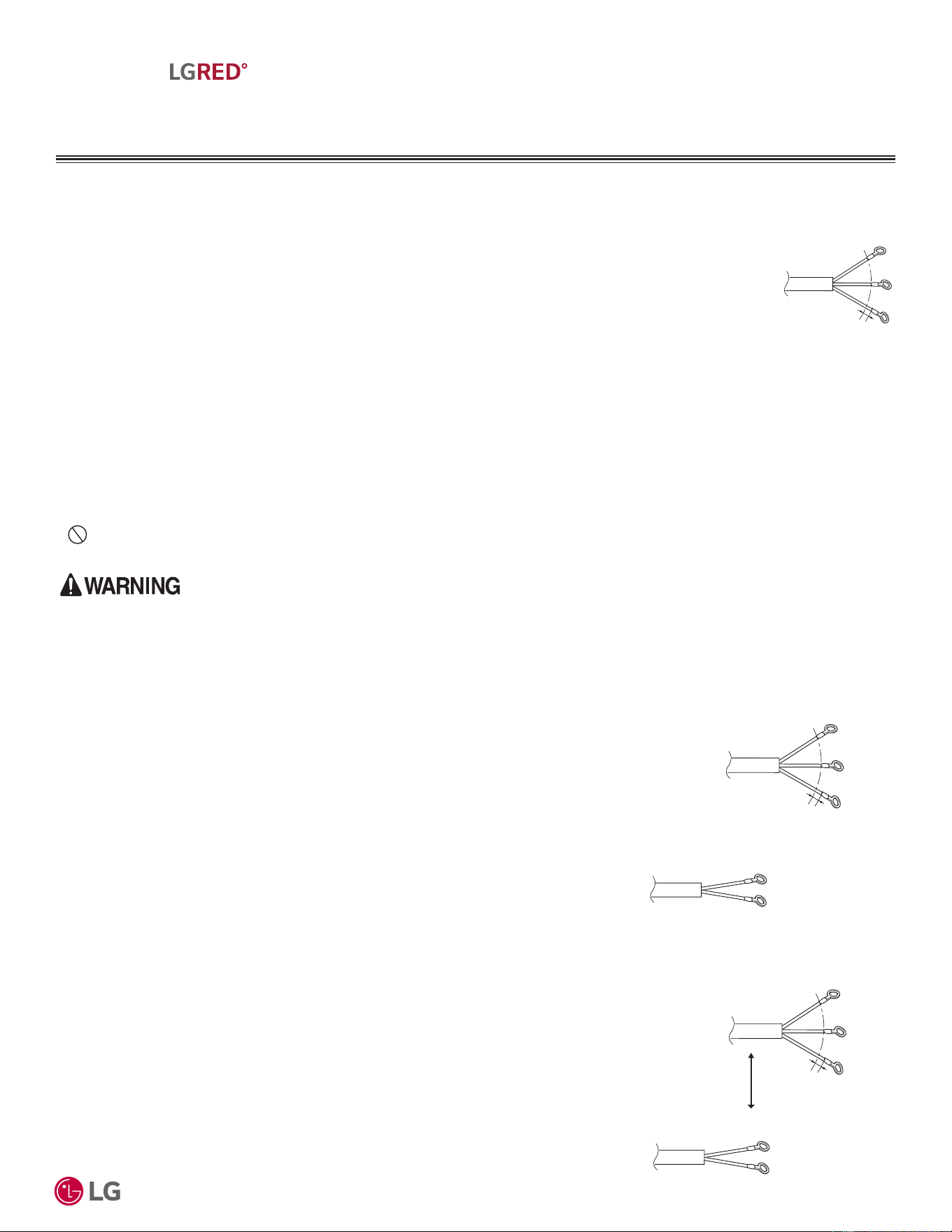
'XHWRRXUSROLF\RIFRQWLQXRXVSURGXFWLQQRYDWLRQVRPHVSHFL¿FDWLRQVPD\FKDQJHZLWKRXWQRWL¿FDWLRQ
©
/*(OHFWURQLFV86$,QF(QJOHZRRG&OLIIV1-$OOULJKWVUHVHUYHG³/*´LVDUHJLVWHUHGWUDGHPDUNRI/*&RUS
53
Electrical Connections
MULTI
F
MAX
MULTI
F
WITH
ELECTRICAL CONNECTIONS
$OZD\VKDYHDWUDLQHGVHUYLFHSURYLGHUSURSHUO\JURXQGWKHRXWGRRUXQLW,IWKHRXWGRRUXQLWLVQRWSURSHUO\JURXQGHGWKHUHLVDULVNRIHOHFWULFVKRFN
SK\VLFDOLQMXU\RUGHDWK
• Multi F and Multi F MAX LGRED systems operate at 1Ø, 208-230V, 60Hz, and power is wired to the
outdoor unit only.
• Power wiring to the outdoor unit(s) must be a minimum of:
- 12 AWG, three (3) conductor for 18,000, 24,000, and 30,000 Btu/h Multi F with LGRED capacities.
- 8 AWG, three (3) conductor for 36,000, 42,000 and 48,000 Btu/h Multi F MAX with LGRED capacities.
• Power wiring must be solid or stranded; and comply with all applicable National Electrical Code (NEC),
UL, and local electrical codes.
• Wiring is allowed for lengths up to the published maximum piping length, plus recommended slack at
both ends (typical slack: 6-12 inches).
• Power supply to the outdoor unit must be selected based on NEC, UL, and local codes. Maximum allowable voltage fluctuation ±10% or
nameplate rated value.
• Properly ground the outdoor unit and indoor unit per NEC and local codes; ground wire must be longer than the common power / communi-
cation wires.
• Firmly connect the wiring so it cannot be easily pulled out.
• Refer to the inside of the chassis cover or control cover for circuit and terminal block diagrams; always match color codes of each wire and
follow wiring diagram.
•
Do not install power wiring to the outdoor unit and the power wiring / communication wiring to the indoor unit / branch distribution Unit
(Multi F MAX outdoor units only) in the same conduit. Use separate conduits.
3RZHU6XSSO\3RZHU:LULQJ6SHFLILFDWLRQVWRWKH
Outdoor Unit
3RZHU:LULQJ&RPPXQLFDWLRQV:LULQJIURPWKH
2'8WRWKH,'8V%'8V
Figure 33: Multi F / Multi F MAX
with LGRED Outdoor Unit Power
Wiring.
Line voltage
(208/230 V)
GN/YL
20 mm
(25/32 inch)
Wiring rewoP
:LULQJ6SHFL¿FDWLRQV
Figure 34: Power Wiring and Communication Wiring
from ODU to IDU / BDU (Multi F MAX with LGRED
Only), and from the BDU to the IDU (Multi F MAX
with LGRED Only).
Figure 35: Power Wiring and Communication Wiring
from ODU to IDU / BDU (Multi F MAX with LGRED
Only), and from the BDU to the IDU (Multi F MAX
with LGRED Only) GREATER THAN 130 feet.
Line voltage
(208/230 V)
GN/YL
20 mm
(25/32 inch)
noitacinummoC
Wiring rewoP
Wiring
L1
L2
Line Voltage
(208/230 V)
GN/YL
20 mm
(25/32 inch)
noitacinummoC
Wiring rewoP
Wiring
L1
L2
18 AWG
Separate At
Least Two (2)
Inches
• The outdoor unit supplies power to the indoor units / branch distribution units (Multi F
MAX with LGRED systems only).
• The outdoor unit also supplies communication to the indoor units / branch distribution
units (Multi F MAX with LGRED systems only).
• Wiring from the outdoor units to the indoor units / branch distribution units (Multi
F MAX with LGRED systems only) must be stranded, shielded or unshielded (if
shielded, it must be grounded to the chassis of the outdoor unit only), and must com-
ply with all applicable National Electrical Code (NEC), UL, and local electrical codes.
• Insulation material as required by local code.
• Rated for continuous exposure of temperatures up to 140°F.
• Firmly attach the wiring; provide slack at both ends but secure in a way to prevent
external forces from being imparted on the terminal block.
• Wiring is allowed for lengths up to the published maximum piping length, plus recom-
mended slack at both ends (typical slack: 6-12 inches).
• Wiring must be completed without splices.
• When the power wire and communication wire length between the outdoor unit and
branch distribution unit, and between the branch distribution unit and the indoor units
GREATER THAN 130 feet:
• Use minimum 14 AWG communication wiring
OR
• Separate the power wiring AT LEAST two (2) inches away from the communication
wiring.
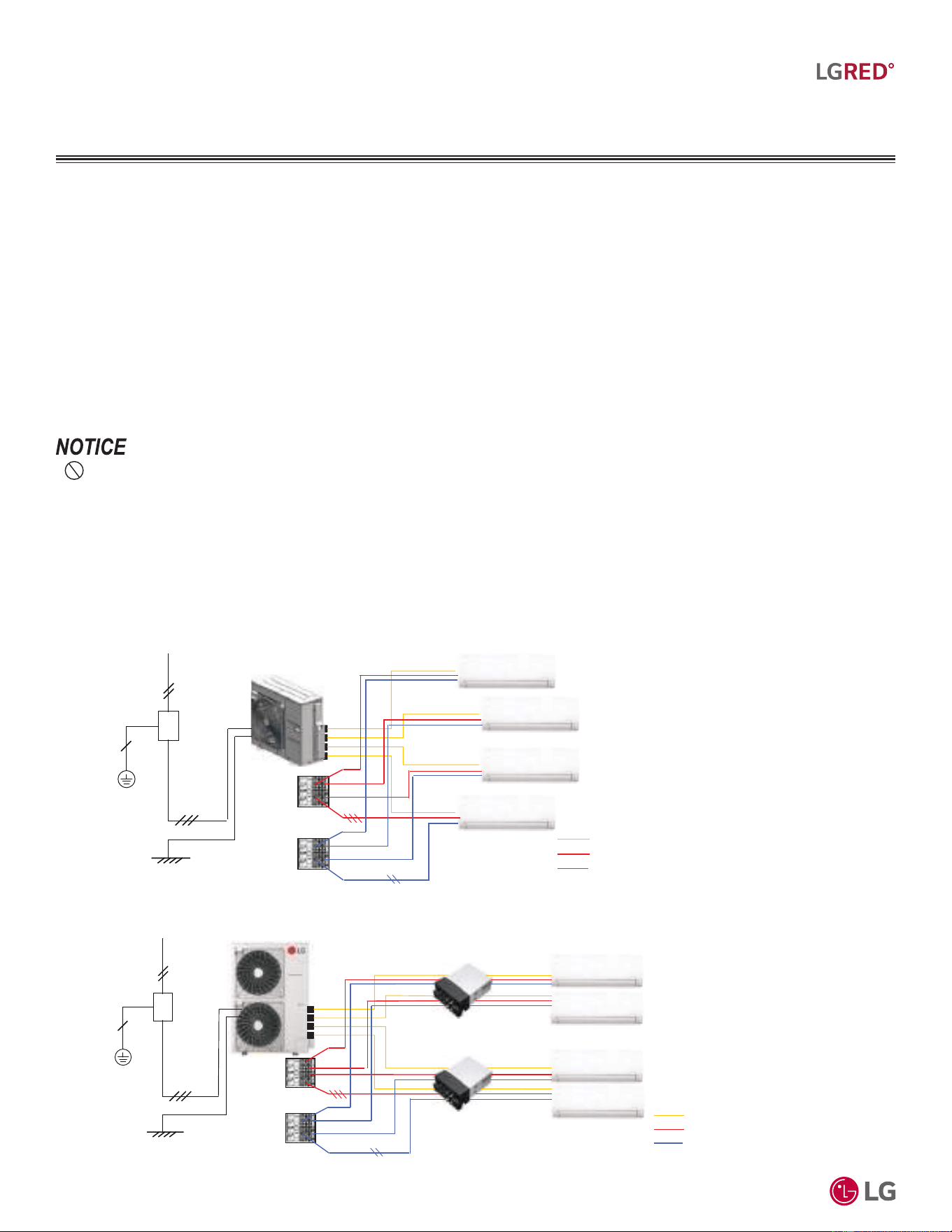
'XHWRRXUSROLF\RIFRQWLQXRXVSURGXFWLQQRYDWLRQVRPHVSHFL¿FDWLRQVPD\FKDQJHZLWKRXWQRWL¿FDWLRQ
©
/*(OHFWURQLFV86$,QF(QJOHZRRG&OLIIV1-$OOULJKWVUHVHUYHG³/*´LVDUHJLVWHUHGWUDGHPDUNRI/*&RUS
54
R32 Multi F and Multi F MAX with LGRED° Outdoor Unit Engineering Manual
MULTI
F
MAX
MULTI
F
WITH
ELECTRICAL CONNECTIONS
• 1HYHUJURXQGWKHVKLHOGRIWKHFRPPXQLFDWLRQVZLULQJWRWKHLQGRRUXQLWEUDQFKGLVWULEXWLRQXQLWIUDPHRURWKHUJURXQGHGHQWLWLHVRI
WKHEXLOGLQJ*URXQGWKHFRPPXQLFDWLRQVZLULQJVKLHOGRQO\DWWKHRXWGRRUXQLW,PSURSHUO\JURXQGLQJWKLVFDEOHFDQFDXVHFRPPXQLFDWLRQV
HUURUV
• 8VHDFRQGXLWIRUWKHSRZHUFDEOHDQGWKHFRPPXQLFDWLRQVFDEOHIURPWKHRXWGRRUXQLWWRWKHLQGRRUXQLWVEUDQFKGLVWULEXWLRQXQLWV(OHFWUL-
FDOLQWHUIHUHQFHP\FDXVHSURGXFWPDOIXQFWLRQ
• 7KHFRPPXQLFDWLRQVZLULQJIURPWKHRXWGRRUXQLWWRWKHLQGRRUXQLWVEUDQFKGLVWULEXWLRQXQLWVPXVWEHVHSDUDWHGDQGLVRODWHGIURPSRZHU
ZLULQJWRWKHRXWGRRUXQLWFRPSXWHUVUDGLRDQGWHOHYLVLRQEURDGFDVWLQJIDFLOLWLHVDVZHOODVPHGLFDOLPDJLQJHTXLSPHQW(OHFWULFDOLQWHUIHU-
HQFHP\FDXVHSURGXFWPDOIXQFWLRQ
Power Wiring / Communications Wiring, Continued.
:LULQJ6SHFL¿FDWLRQV
Multi F with LGRED Systems (Outdoor Unit to Indoor Units):
• Power wiring must be a minimum of 14 AWG, three (3) conductor for 18,000, 24,000, 30,000 and 36,000 Btu/h Multi F capacities.
• Communications wiring must be a minimum of 18 AWG, two (2) conductor for 18,000, 24,000, 30,000 and 36,000 Btu/h Multi F capacities.
Multi F MAX with LGRED Systems (Outdoor Unit to Branch Distribution Units):
• Power wiring must be a minimum of 14 AWG, three (3) conductor for 48,000, 54,000, and 60,000 Btu/h Multi F MAX capacities.
• Communications wiring must be a minimum of 18 AWG, two (2) conductor for 48,000, 54,000, and 60,000 Btu/h Multi F MAX capacities.
Multi F MAX with LGRED Systems (Branch Distribution Units to Indoor Units):
• Power wiring must be a minimum of 14 AWG, three (3) conductor for 48,000, 54,000, and 60,000 Btu/h Multi F MAX capacities.
• Communications wiring must be a minimum of 18 AWG, two (2) conductor for 48,000, 54,000, and 60,000 Btu/h Multi F MAX capacities.
Figure 36: Example of a Multi F with LGRED System General Power / Communications System Schematic.
Figure 37: Example of a Multi F MAX with LGRED System General Power / Communications System Schematic.
IDU
Power
Comm.
ODU
Power Supply
Circuit Breaker
Ground Wiring
Piping
Power Wiring
Communication
Wiring
IDU
Power
Comm.
ODU
Power Supply
Circuit Breaker
Ground Wiring
BDU
Piping
Power Wiring
Communication
Wiring
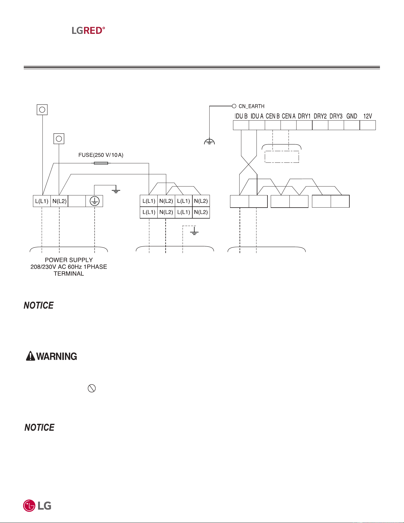
'XHWRRXUSROLF\RIFRQWLQXRXVSURGXFWLQQRYDWLRQVRPHVSHFL¿FDWLRQVPD\FKDQJHZLWKRXWQRWL¿FDWLRQ
©
/*(OHFWURQLFV86$,QF(QJOHZRRG&OLIIV1-$OOULJKWVUHVHUYHG³/*´LVDUHJLVWHUHGWUDGHPDUNRI/*&RUS
55
Electrical Connections
MULTI
F
MAX
MULTI
F
WITH
ELECTRICAL CONNECTIONS
0XOWL)ZLWK/*5('6\VWHPV
• $OOILHOGVXSSOLHGZLULQJFRPSRQHQWVDQGPDWHULDOVPXVWFRPSO\ZLWKDOODSSOLFDEOHQDWLRQDOVWDWHDQGORFDOFRGHVDQGUHTXLUHPHQWV
,PSURSHUZLULQJZLOOUHVXOWLQILUHHOHFWULFVKRFNFDXVLQJSK\VLFDOLQMXU\RUGHDWK
• *URXQGZLULQJLVUHTXLUHGWRSUHYHQWDFFLGHQWDOHOHFWULFDOVKRFNGXULQJFXUUHQWOHDNDJHFRPPXQLFDWLRQSUREOHPVIURPHOHFWULFDOQRLVHDQG
PRWRUFXUUHQWOHDNDJH 'RQRWFRQQHFWWKHJURXQGOLQHWRWKHSLSHV7KHUHLVDULVNRIILUHHOHFWULFVKRFNH[SORVLRQUHVXOWLQJLQSK\VL-
FDOLQMXU\RUGHDWK
• ,QVWDOODPDLQVKXWRIIVZLWFKRUFLUFXLWEUHDNHUWKDWLQWHUUXSWVDOOSRZHUVRXUFHVVLPXOWDQHRXVO\7KHUHLVDULVNRIILUHHOHFWULFVKRFNH[SOR-
VLRQUHVXOWLQJLQSK\VLFDOLQMXU\RUGHDWK
• 7HUPLQDOEORFNODEHOVDSSHDUDQFHVDQGORFDWLRQZLOOYDU\GHSHQGLQJRQRXWGRRUXQLWPRGHO
• 0DLQWDLQSRODULW\WKURXJKRXWWKHFRPPXQLFDWLRQQHWZRUN7KHV\VWHPZLOOPDOIXQFWLRQLIQRWSURSHUO\ZLUHG
• $OOILHOGVXSSOLHGZLULQJFRPSRQHQWVVL]HVDQGPDWHULDOVPXVWFRPSO\ZLWKDOODSSOLFDEOHQDWLRQDOVWDWHDQGORFDOFRGHVDQGUHTXLUH-
PHQWV)DLOXUHWRLQVWDOOSURSHUHOHFWULFDOFRPSRQHQWVFDQUHVXOWLQSURSHUW\GDPDJHDQGHTXLSPHQWPDOIXQFWLRQ
• *URXQGZLULQJLVUHTXLUHGWRSUHYHQWFRPPXQLFDWLRQSUREOHPVIURPHOHFWULFDOQRLVHDQGPRWRUFXUUHQWOHDNDJH)DLOXUHWRSURYLGHSURSHU
JURXQGZLULQJFDQUHVXOWLQSURSHUW\GDPDJHDQGHTXLSPHQWPDOIXQFWLRQ
• ,QVWDOODPDLQVKXWRIIVZLWFKRUFLUFXLWEUHDNHUWKDWLQWHUUXSWVDOOSRZHUVRXUFHVVLPXOWDQHRXVO\)DLOXUHWRLQVWDOOSURSHUHOHFWULFFRPSRQHQWV
ZLOOUHVXOWLQSURSHUW\GDPDJHDQGHTXLSPHQWPDOIXQFWLRQ
.80;$$FDQVXSSRUWQRPRUHWKDQWZRLQGRRUXQLWV.80;$$FDQVXSSRUWWZRRUWKUHHLQGRRUXQLWV.80;$$FDQVXSSRUWWZRWKUHHRU
IRXULQGRRUXQLWV(QVXUHWKHFRPPXQLFDWLRQZLULQJDQGSRZHUZLULQJIURPWKHRXWGRRUXQLWWRWKHLQGRRUXQLWVLVLQVWDOOHGFRUUHFWO\IRUWKHV\VWHPDQG
WKHFKRVHQDSSOLFDWLRQ
Figure 38: Multi F with LGRED KUMXA181A, KUMXA241A, and KUMXA301A System Power Wiring and Communications Cable.
BK
Central
BL
OR
BL
BR
BR
BL
GN/YL
BL
OR
3(A) 4(B)
3(A) 4(B)
3(A) 4(B)
OR
BL
To Indoor Unit
Power Supply
To Indoor Unit
Communication
CN_INPUT
_BROWN
CN_INPUT
_BLUE
Connect the power wiring and communication wiring
according to the number of indoor units installed.
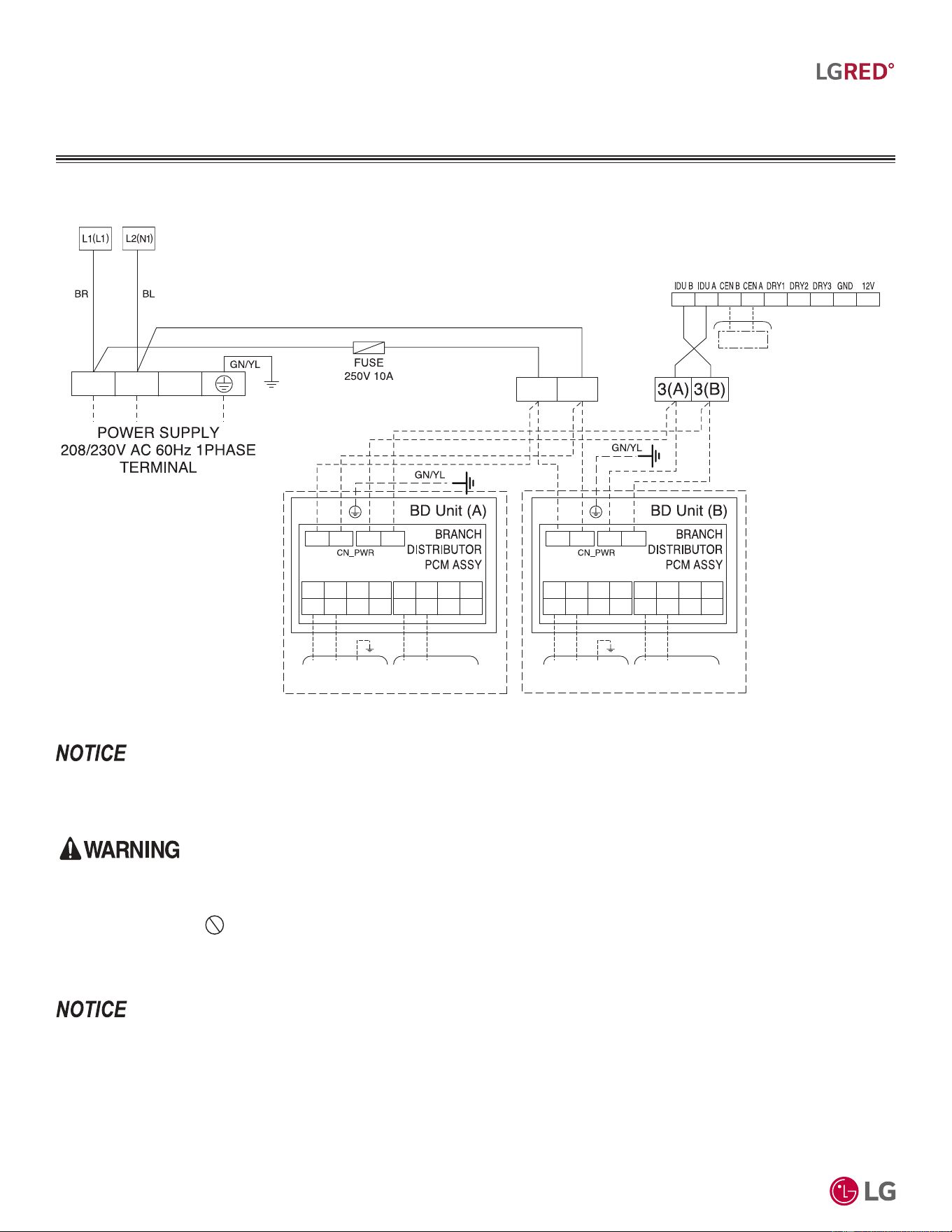
'XHWRRXUSROLF\RIFRQWLQXRXVSURGXFWLQQRYDWLRQVRPHVSHFL¿FDWLRQVPD\FKDQJHZLWKRXWQRWL¿FDWLRQ
©
/*(OHFWURQLFV86$,QF(QJOHZRRG&OLIIV1-$OOULJKWVUHVHUYHG³/*´LVDUHJLVWHUHGWUDGHPDUNRI/*&RUS
56
R32 Multi F and Multi F MAX with LGRED° Outdoor Unit Engineering Manual
MULTI
F
MAX
MULTI
F
WITH
• $OOILHOGVXSSOLHGZLULQJFRPSRQHQWVDQGPDWHULDOVPXVWFRPSO\ZLWKDOODSSOLFDEOHQDWLRQDOVWDWHDQGORFDOFRGHVDQGUHTXLUHPHQWV
,PSURSHUZLULQJZLOOUHVXOWLQILUHHOHFWULFVKRFNFDXVLQJSK\VLFDOLQMXU\RUGHDWK
• *URXQGZLULQJLVUHTXLUHGWRSUHYHQWDFFLGHQWDOHOHFWULFDOVKRFNGXULQJFXUUHQWOHDNDJHFRPPXQLFDWLRQSUREOHPVIURPHOHFWULFDOQRLVHDQG
PRWRUFXUUHQWOHDNDJH 'RQRWFRQQHFWWKHJURXQGOLQHWRWKHSLSHV7KHUHLVDULVNRIILUHHOHFWULFVKRFNH[SORVLRQUHVXOWLQJLQSK\VL-
FDOLQMXU\RUGHDWK
• ,QVWDOODPDLQVKXWRIIVZLWFKRUFLUFXLWEUHDNHUWKDWLQWHUUXSWVDOOSRZHUVRXUFHVVLPXOWDQHRXVO\7KHUHLVDULVNRIILUHHOHFWULFVKRFNH[SOR-
VLRQUHVXOWLQJLQSK\VLFDOLQMXU\RUGHDWK
• 7HUPLQDOEORFNODEHOVDSSHDUDQFHVDQGORFDWLRQZLOOYDU\GHSHQGLQJRQRXWGRRUXQLWPRGHO
• 0DLQWDLQSRODULW\WKURXJKRXWWKHFRPPXQLFDWLRQQHWZRUN7KHV\VWHPZLOOPDOIXQFWLRQLIQRWSURSHUO\ZLUHG
• $OOILHOGVXSSOLHGZLULQJFRPSRQHQWVVL]HVDQGPDWHULDOVPXVWFRPSO\ZLWKDOODSSOLFDEOHQDWLRQDOVWDWHDQGORFDOFRGHVDQGUHTXLUH-
PHQWV)DLOXUHWRLQVWDOOSURSHUHOHFWULFDOFRPSRQHQWVFDQUHVXOWLQSURSHUW\GDPDJHDQGHTXLSPHQWPDOIXQFWLRQ
• *URXQGZLULQJLVUHTXLUHGWRSUHYHQWFRPPXQLFDWLRQSUREOHPVIURPHOHFWULFDOQRLVHDQGPRWRUFXUUHQWOHDNDJH)DLOXUHWRSURYLGHSURSHU
JURXQGZLULQJFDQUHVXOWLQSURSHUW\GDPDJHDQGHTXLSPHQWPDOIXQFWLRQ
• ,QVWDOODPDLQVKXWRIIVZLWFKRUFLUFXLWEUHDNHUWKDWLQWHUUXSWVDOOSRZHUVRXUFHVVLPXOWDQHRXVO\)DLOXUHWRLQVWDOOSURSHUHOHFWULFFRPSRQHQWV
ZLOOUHVXOWLQSURSHUW\GDPDJHDQGHTXLSPHQWPDOIXQFWLRQ
.80;$$FDQVXSSRUWXSWRWZREUDQFKGLVWULEXWLRQXQLWVDQGXSWR¿YHLQGRRUXQLWV.80;$$FDQVXSSRUWXSWRWZREUDQFKGLVWULEXWLRQXQLWV
DQGXSWRVL[LQGRRUXQLWV.80;$$FDQVXSSRUWXSWRWZREUDQFKGLVWULEXWLRQXQLWVDQGXSWRHLJKWLQGRRUXQLWV(QVXUHWKHFRPPXQLFDWLRQZLU-
LQJDQGSRZHUZLULQJIURPWKHRXWGRRUXQLWWRWKHLQGRRUXQLWVLVLQVWDOOHGFRUUHFWO\IRUWKHV\VWHPDQGWKHFKRVHQDSSOLFDWLRQ
Figure 39: Multi F MAX with LGRED KUMXA181A, KUMXA241A, and KUMXA301A System Power Wiring and Communications Cable.
ELECTRICAL CONNECTIONS
0XOWL)0$;ZLWK/*5('6\VWHPV
Central
BL
OR
L(L1) N(L2) 3(A) 4(B) L(L1) N(L2) 3(A) 4(B)
L(L1) N(L2) L(L1) N(L2)
L(L1) N(L2) L(L1)
Indoor Unit
Power Supply
Indoor Unit
Communication
N(L2)
3(A) 4(B) 3(A) 4(B)
3(A) 4(B) 3(A) 4(B)
L(L1) N(L2) L(L1) N(L2)
L(L1) N(L2) L(L1)
Indoor Unit
Power Supply
Indoor Unit
Communication
N(L2)
3(A) 4(B) 3(A) 4(B)
3(A) 4(B) 3(A) 4(B)
Connect power wiring and communications
wiring according to the number of indoor units
installed.
L(L1) N(L2)
L(L1) N(L2)
L1_BR N1_BL
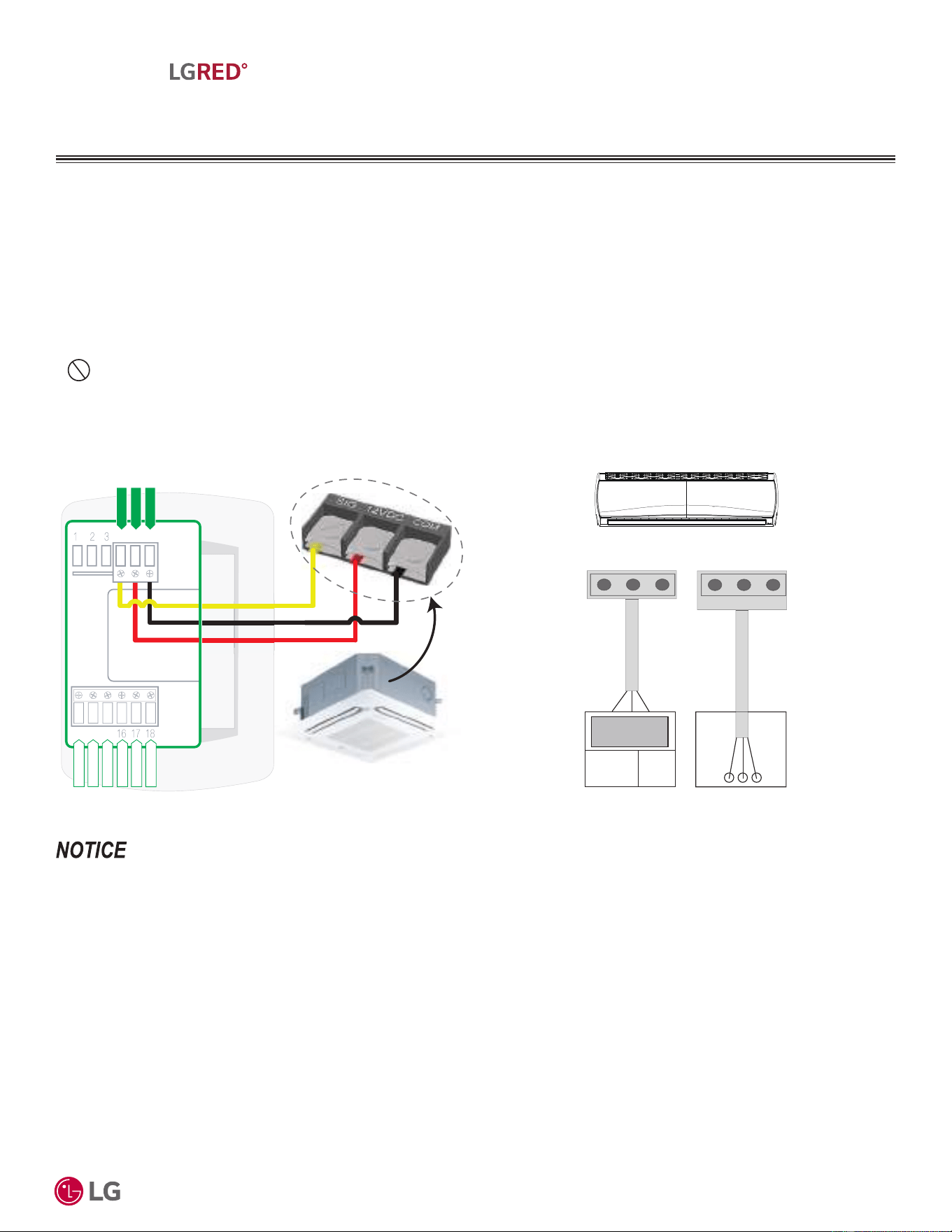
'XHWRRXUSROLF\RIFRQWLQXRXVSURGXFWLQQRYDWLRQVRPHVSHFL¿FDWLRQVPD\FKDQJHZLWKRXWQRWL¿FDWLRQ
©
/*(OHFWURQLFV86$,QF(QJOHZRRG&OLIIV1-$OOULJKWVUHVHUYHG³/*´LVDUHJLVWHUHGWUDGHPDUNRI/*&RUS
57
Electrical Connections
MULTI
F
MAX
MULTI
F
WITH
ELECTRICAL CONNECTIONS
,QGRRU8QLWV&RQWUROOHUV
From Indoor Units to Remote Controllers
• Communication cable from indoor unit to remote controller(s) is to be 22 AWG, 3-conductor, twisted, stranded, unshielded. Wiring must
comply with all applicable local and national codes.
• If using the LG Controller / Extension cable and the length needs to be extended, the LG Extension Kit (sold separately) must be used. A
maximum of four (4) kits (up to 165 feet) can be used.
• Remote controllers have hardwired connections: SIG - 12V - GND (Comm.) terminals.
• Indoor unit controller connections depend on type of indoor unit being installed. Some indoor units use terminal block connections; other
indoor units use Mollex connections. See diagrams below for the two options. Refer to the wiring diagram schematic found in the indoor unit
itself, or to the indoor unit wiring diagrams in the Engineering Manuals for more information.
• NEVER splice, cut, or extend cable length with field provided cable. Always include enough cable to cover distance between the indoor
unit and the remote controller.
• Set the indoor unit operating parameters using DIP switches, or by setting up the remote controller. Refer to the indoor unit installation
manuals for more details.
&DEOHFRQQHFWHGWR=RQH&RQWUROOHULVWKHIDFWRU\GHIDXOWFRQQHFWLRQ
Figure 40: One Example of Indoor Unit to Zone Controller Connection. Figure 41: Another Example of Indoor Unit to Zone Controller
Connection.
CN-REMO
Indoor Unit
RD
BK
YL
Front
CN-REMO
RDBKYL
Back
BACnet+
BACnet-
BACnet Common
Not used
Not used
Not used
Common
456
13 14 15
Typical Indoor Unit
Signal
12VDC
YL
RD
BK
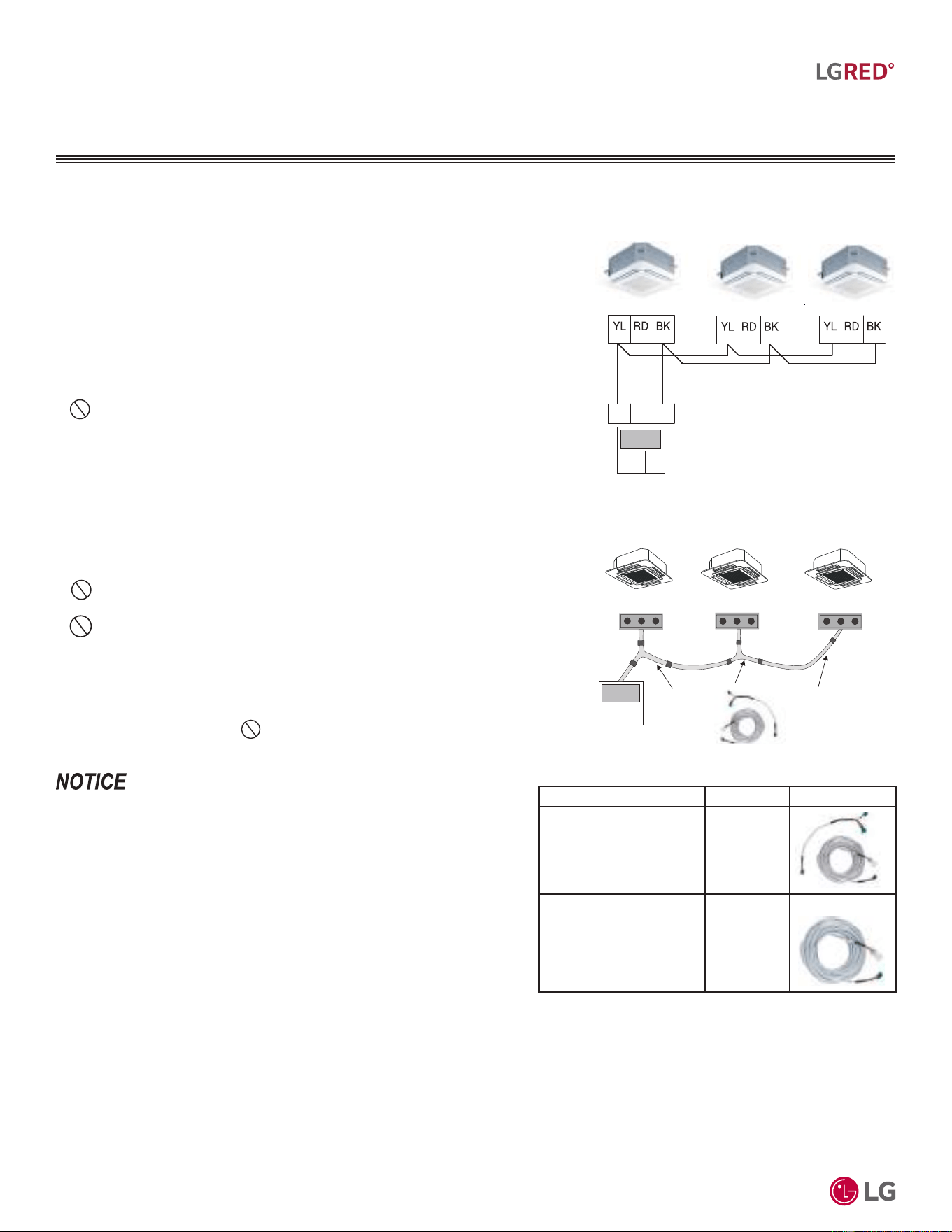
'XHWRRXUSROLF\RIFRQWLQXRXVSURGXFWLQQRYDWLRQVRPHVSHFL¿FDWLRQVPD\FKDQJHZLWKRXWQRWL¿FDWLRQ
©
/*(OHFWURQLFV86$,QF(QJOHZRRG&OLIIV1-$OOULJKWVUHVHUYHG³/*´LVDUHJLVWHUHGWUDGHPDUNRI/*&RUS
58
R32 Multi F and Multi F MAX with LGRED° Outdoor Unit Engineering Manual
MULTI
F
MAX
MULTI
F
WITH
Accessory Model No. Image
Wired Remote Group
Control Cable Assembly -
Required for connecting
multiple indoor units to a
control group
PZCWRCG3
Wired Remote / Wired
Remote Extension Cable -
Required for extending the
distance between indoor
units or remote controllers
in a control group
PZCWRC1
Table 33: Accessories for Some Group Control Applications.
Between Multiple Indoor Units Operating as a
Group (Group Control)
If any indoor units were specified to operate in unison:
• Before running cable, decide which indoor unit will be the “Main.” The other indoor
units in that group will be designated as “Sub(s).” The zone controller will be connected
to the “Main.”
• Set the pertinent DIP switch at each indoor unit to identify the Main and Sub(s). On
wall mounted indoor unit models, set the assignment using the handheld remote
controller.
• Use a daisy chain configuration and connect all of the group’s indoor units together
starting at the “Main” unit.
•
NEVER splice, cut, or extend cable length with field provided cable. Always
include enough cable to cover distance between all components.
For indoor units with hardwired connections SIG - 12V - GND (Comm.)
terminals:
• From the controller to the main indoor unit, use 22 AWG, 3-conductor, twisted, strand-
ed, unshielded. All wiring must comply with all applicable local / national codes.
• From the main indoor unit to the sub indoor unit(s), daisy chain using 22 AWG, 3-con-
ductor, twisted, stranded, unshielded. All wiring must comply with all applicable local /
national codes.
•( Do not attach wire to 12VDC terminal to the sub indoor units). All wiring must
comply with all applicable local and national codes.
• NEVER splice, cut, or extend cable length; always include enough cable to cover
distance between all components.
For indoor units with CN-REMO connections:
Use one (or multiple) Group Control Kit(s) (sold separately) containing extension and
Y-splitter cables. Use one (1) group control cable kit for each indoor unit in the group
except for the last indoor unit. NEVER splice, cut, or extend cable length with field
provided cable.
• &DEOHFRQQHFWHGWR]RQHFRQWUROOHULVWKHIDFWRU\GHIDXOWFRQQHFWLRQ
• ,QGRRUXQLWFRQQHFWLRQVGHSHQGRQLQGRRUXQLWW\SH
Figure 42: Example of Indoor Unit Group to Zone
Controller Connections (Sig-12V-GND [Comm.]
Terminal).
Figure 43: Example of Indoor Unit Group to Zone
Controller Connections (CN-REMO).
Main Indoor Unit
Indoor Unit
Indoor Unit
Signal
12VDC Comm.
Signal
12VDC Comm.
45
6
Signal
12VDC Comm.
Signal
12VDC Comm.
CN-REMO
On All Indoor Unit Styles
CN-REMO
On All Indoor Unit Styles
CN-REMO
On All Indoor Unit Styles
LG
Supplied
LG Supplied Group Control Kit (PZCWRCG3)
ELECTRICAL CONNECTIONS
,QGRRU8QLWV&RQWUROOHUV
General Specifications
• Wired remote controllers can be connected to all indoor unit types.
• Wireless controllers can be used in conjunction with wired remote
controllers.
• A dry contact unit can be connected with a central controller simultaneously.
- The main indoor unit is recognized by the dry contact unit and the central
controller.
- The central controller can control indoor units after setting the address of
the main indoor unit only.
- Sub indoor unit cannot be individually controlled by central controller.
- Sub indoor unit will operate like main indoor unit.
• If an error occurs with the indoor unit, the error will be displayed on the wired remote controller.
• The following functions are available with group control:
• Selection of operation options (operation/mode/set temperature)
• Control of air flow rate (High / Medium / Low)

PIPING
LIMITATIONS AND
PLACEMENT
CONSIDERATIONS
Piping Limitations on page 60
Selecting the Best Location for the Outdoor Unit on page 62
Outdoor Unit Clearance Requirements on page 65
Installing Outdoor Units Indoors on page 68
6HOHFWLQJWKH%HVW/RFDWLRQIRUWKH,QGRRU8QLWV
Branch Distribution Units on page 71
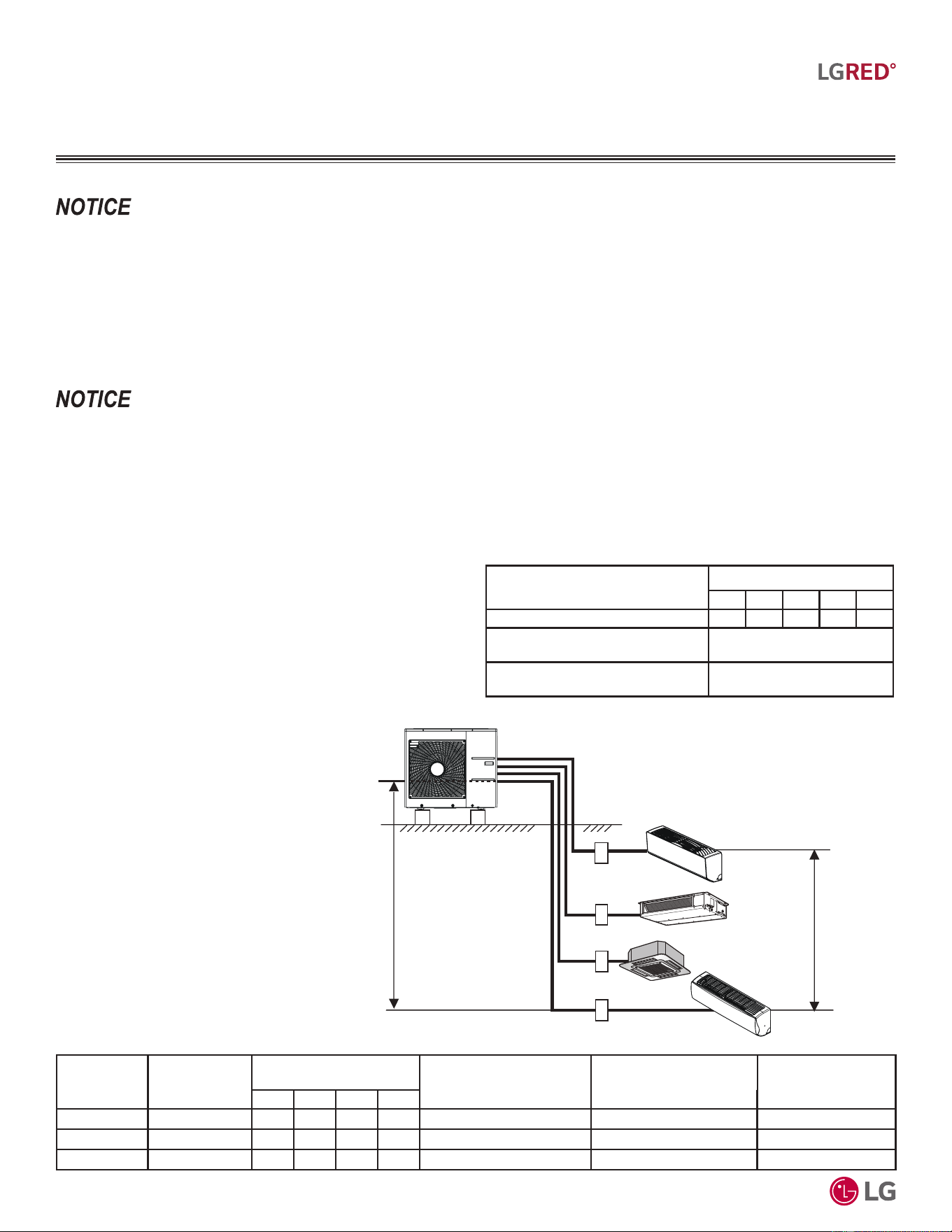
'XHWRRXUSROLF\RIFRQWLQXRXVSURGXFWLQQRYDWLRQVRPHVSHFL¿FDWLRQVPD\FKDQJHZLWKRXWQRWL¿FDWLRQ
©
/*(OHFWURQLFV86$,QF(QJOHZRRG&OLIIV1-$OOULJKWVUHVHUYHG³/*´LVDUHJLVWHUHGWUDGHPDUNRI/*&RUS
60
R32 Multi F and Multi F MAX with LGRED° Outdoor Unit Engineering Manual
MULTI
F
MAX
MULTI
F
WITH
PIPING LIMITATIONS
)ROORZLQJSDJHVSUHVHQW0XOWL)0$;SLSLQJOLPLWDWLRQVDQGDUHIRULOOXVWUDWLYHSXUSRVHVRQO\'HVLJQHUVDUHKLJKO\HQFRXUDJHGWRXVH/$76ZKHQ
GHVLJQLQJ0XOWL)0$;V\VWHPV
9DULRXVWRROVDUHDYDLODEOHWRDVVLVWLQSURSHUO\GHVLJQLQJ/*5VSOLWV\VWHPV5HIHUWRWKH³5$SSOLFDWLRQ*XLGH´WKH³6LPSOH&DOFXODWRUIRU&D-
SDFLW\5HIULJHUDQW&KDUJHDQG(63´WKH³/*$LU&RQGLWLRQHU7HFKQLFDO6ROXWLRQV´/$76VRIWZDUHSURJUDPDQGWKHORFDO/*6DOHV5HSUHVHQWDWLYH
Max. 49.2 feet
Max. 24.6 feet
A
B
C
D
Example of a Multi F with
LGRED System
Example: KUMXA301A outdoor unit with four (4)
indoor units connected.
ODU: Outdoor Unit.
IDU: Indoor Unit.
A, B, C, D: Pipes from Outdoor Unit to Indoor Unit.
Outdoor Unit
Minimum
Length for
Each Pipe (ft.)
Maximum Piping Length
to Each Indoor Unit (ft.)
Maximum Height
Difference (Max. [ft.])
Outdoor Unit ~ Indoor Unit
Maximum Height
Difference (Max. [ft.])
Indoor Unit ~ Indoor Unit
Maximum Total
Piping Length for
Each System (ft.)
ABCD
KUMXA181A
9.8 82.0 82.0 - - 49.2 24.6 164
KUMXA241A
9.8 82.0 82.0 82.0 - 49.2 24.6 246.1
KUMXA301A
9.8 82.0 82.0 82.0 82.0 49.2 24.6 246.1
Table 34: Multi F with LGRED Outdoor Unit Refrigerant Piping System Limitations.
Device Connection Limitations
• The minimum number of connected and operating indoor units to Multi F / Multi F MAX with LGRED systems is two, taking into consider-
ation the minimum combination ratio.
• The maximum number of indoor units for each Multi F / Multi F MAX with LGRED heat pump system is:
KUMXA181A = 2 KUMXA241A = 3 KUMXA301A = 4 KUMXA361A= 5 KUMXA421A = 6 KUMXA481A = 8
One of the most critical elements of multi-zone systems is the refrigerant piping. The following pages list pipe length limits that must be
followed in the design of Multi F and Multi F MAX with LGRED refrigerant pipe systems:
Table 35: Equivalent Piping Length for Elbows, Y-branches, and Branch
Distribution Units.
1
Kit contains two Y-branches: one for liquid and one for vapor.
Component
Size (Inches)
1/4 3/8 1/2 5/8 3/4
Elbow (ft.) 0.5 0.6 0.7 0.8 1.2
Y-Branch Kit (ft., Multi F MAX with
LGRED systems only)
1
1.6
Branch Distribution Unit (ft., Multi F
MAX with LGRED systems only)
8.2
Using Refrigerant Components
Field-supplied elbows are allowed as long as they are designed for
use with R32 refrigerant. The designer, however, must be cautious
with the quantity and size of fittings used, and must account for the
additional pressure losses in equivalent pipe length calculation for
each branch. The equivalent pipe length of each elbow must be
added to each pipe segment.
)RUDOORFDWHGFDSDFLW\LQIRUPDWLRQVHHWKHFRPELQDWLRQWDEOHVLQWKH³0XOWL)0XOWL)0$;ZLWK/*5('&RPELQDWLRQ'DWD0DQXDO´RQ
ZZZOJKYDFFRP)RUSHUIRUPDQFHGDWDVHH³0XOWL)0XOWL)0$;ZLWK/*5('3HUIRUPDQFH'DWD0DQXDO´RQZZZOJKYDFFRP
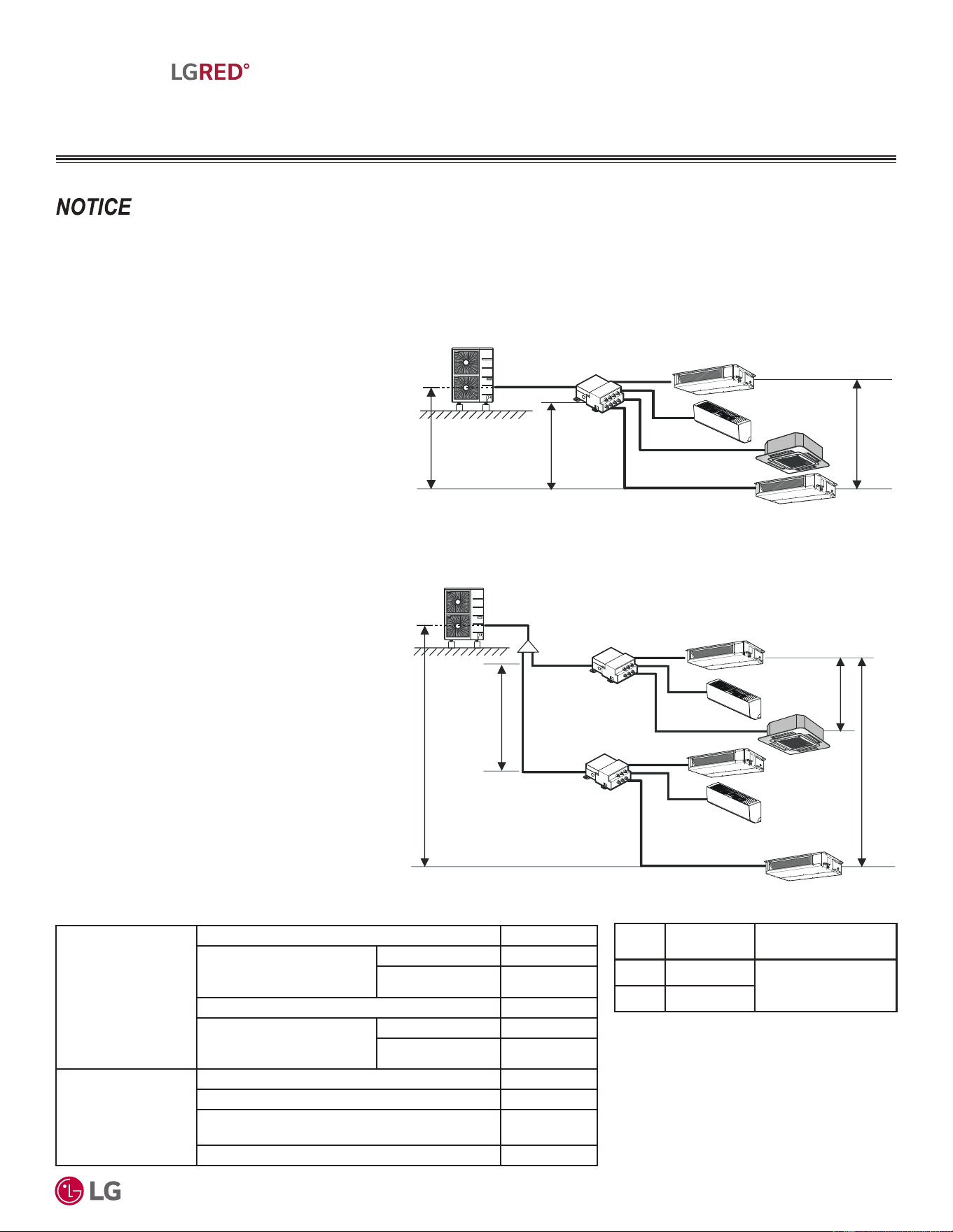
'XHWRRXUSROLF\RIFRQWLQXRXVSURGXFWLQQRYDWLRQVRPHVSHFL¿FDWLRQVPD\FKDQJHZLWKRXWQRWL¿FDWLRQ
©
/*(OHFWURQLFV86$,QF(QJOHZRRG&OLIIV1-$OOULJKWVUHVHUYHG³/*´LVDUHJLVWHUHGWUDGHPDUNRI/*&RUS
61
Piping Limitations and Placement Considerations
MULTI
F
MAX
MULTI
F
WITH
PIPING LIMITATIONS
)ROORZLQJSDJHVSUHVHQW0XOWL)0$;SLSLQJOLPLWDWLRQVDQGDUHIRULOOXVWUDWLYHSXUSRVHVRQO\'HVLJQHUVDUHKLJKO\HQFRXUDJHGWRXVH/$76ZKHQ
GHVLJQLQJ0XOWL)0$;V\VWHPV
9DULRXVWRROVDUHDYDLODEOHWRDVVLVWLQSURSHUO\GHVLJQLQJ/*5VSOLWV\VWHPV5HIHUWRWKH³5$SSOLFDWLRQ*XLGH´WKH³6LPSOH&DOFXODWRUIRU&D-
SDFLW\5HIULJHUDQW&KDUJHDQG(63´WKH³/*$LU&RQGLWLRQHU7HFKQLFDO6ROXWLRQV´/$76VRIWZDUHSURJUDPDQGWKHORFDO/*6DOHV5HSUHVHQWDWLYH
Example: KUMXA361A outdoor unit with four (4)
indoor units and one (1) branch distribution unit
connected.
ODU: Outdoor Unit.
IDU: Indoor Unit.
BDU: Branch Distribution Unit.
A: Main Pipe.
B: Branch Pipe (Branch Distribution Unit to Indoor
Unit[s]).
Example of a Multi F MAX with LGRED System with One Branch Distribution
Unit
A
h2 IHHW
h3 IHHW
h1 IHHW
BDU
ODU
IDU
IDU
IDU
IDU
B
B
B
B
B
A
h2 IHHW
A
h3 IHHW
KIHHW
h1 IHHW
BDU Y-Branch
BDU
IDU
A
ODU
IDU
IDU
IDU
IDU
IDU
B
B
B
B
B
Example of a Multi F MAX with LGRED System with Two Branch Distribution
Units
Example: KUMXA421A outdoor unit with six
(6) indoor units and two (2) branch distribution
units connected.
ODU: Outdoor Unit.
IDU: Indoor Unit.
BDU: Branch Distribution Unit(s).
A: Main Pipe.
B: Branch Pipe (Branch Distribution Unit[s] to Indoor
Unit[s]).
Table 36: Multi F MAX with LGRED Outdoor Unit Refrigerant Piping System Limitations.
Pipe Length
(ELF = Equivalent
Length of pipe in
Feet)
7RWDOSLSLQJOHQJWKȉ$ȉ% IHHW
Main pipe (Outdoor Unit to
Branch Distribution Units:
A)
0LQLPXPIȉ$ 16.4 feet
0D[LPXPȉ$ IHHW
7RWDOEUDQFKSLSLQJOHQJWKȉ% IHHW
Branch pipe (Branch
Distribution Units to Indoor
Units: B)
Minimum 16.4 feet
Maximum IHHW
Elevation Differential
(All Elevation
Limitations are
Measured in Actual
Feet)
If outdoor unit is above or below indoor unit (h1) IHHW
Between the farthest two indoor units (h2) IHHW
Between branch distribution unit and farthest
connected indoor unit(s) (h3)
IHHW
Between branch distribution units (h4) IHHW
Table 37: Multi F MAX with LGRED Piping Sizes.
Piping
Main Pipe A
(inch)
Branch Pipe B
Liquid Ø3/8
Depends on the size
of the indoor unit piping
Vapor Ø3/4
'XHWRRXUSROLF\RIFRQWLQXRXVSURGXFWLQQRYDWLRQVRPHVSHFL¿FDWLRQVPD\FKDQJHZLWKRXWQRWL¿FDWLRQ
©
/*(OHFWURQLFV86$,QF(QJOHZRRG&OLIIV1-$OOULJKWVUHVHUYHG³/*´LVDUHJLVWHUHGWUDGHPDUNRI/*&RUS
62
R32 Multi F and Multi F MAX with LGRED° Outdoor Unit Engineering Manual
MULTI
F
MAX
MULTI
F
WITH
PLACEMENT CONSIDERATIONS
DANGER
Selecting the Best Location for the Outdoor Unit(s)
• 'RQRWLQVWDOOWKHXQLWLQDQDUHDZKHUHFRPEXVWLEOHJDVZLOOJHQHUDWHIORZVWDJQDWHRUOHDN7KHVHFRQGLWLRQVFDQFDXVHDILUHUHVXOW-
LQJLQERGLO\LQMXU\RUGHDWK
• 'RQRWLQVWDOOWKHXQLWLQDORFDWLRQZKHUHDFLGLFVROXWLRQDQGVSUD\VXOIXUDUHRIWHQXVHGDVLWFDQFDXVHERGLO\LQMXU\RUGHDWK
• 'RQRWXVHWKHXQLWLQHQYLURQPHQWVZKHUHRLOVWHDPRUVXOIXULFJDVDUHSUHVHQWDVLWFDQFDXVHERGLO\LQMXU\RUGHDWK
Select a location for installing the outdoor unit that will meet the following conditions:
Dos
• :KHUHWKHUHLVHQRXJKVWUHQJWKWREHDUWKHZHLJKWRIWKHRXWGRRUXQLW
• $ORFDWLRQWKDWDOORZVIRURSWLPXPDLUIORZDQGLVHDVLO\DFFHVVLEOHIRULQVSHFWLRQPDLQWHQDQFHDQGVHUYLFH
• :KHUHSLSLQJEHWZHHQWKHRXWGRRUXQLWDQGLQGRRUXQLWDQGEUDQFKGLVWULEXWLRQXQLW>V@LI0XOWL)0$;LVZLWKLQDOORZDEOHOLPLWV
• ,QFOXGHVSDFHIRUGUDLQDJHWRHQVXUHFRQGHQVDWHIORZVSURSHUO\RXWRIWKHXQLWZKHQLWLVLQKHDWLQJPRGH $YRLGSODFLQJWKHRXWGRRUXQLW
LQDORZO\LQJDUHDZKHUHZDWHUFRXOGDFFXPXODWH
• ,IWKHRXWGRRUXQLWLVLQVWDOOHGLQDKLJKO\KXPLGHQYLURQPHQWQHDUDQRFHDQODNHHWFHQVXUHWKDWWKHVLWHLVZHOOYHQWLODWHGDQGKDVDORW
RIQDWXUDOOLJKW([DPSOH,QVWDOORQDURRIWRS
Do Nots
• :KHUHLWZLOOEHVXEMHFWHGWRGLUHFWWKHUPDOUDGLDWLRQIURPRWKHUKHDWVRXUFHVRUDQDUHDWKDWZRXOGH[SRVHWKHRXWGRRUXQLWWRKHDWRU
VWHDPOLNHGLVFKDUJHIURPERLOHUVWDFNVFKLPQH\VVWHDPUHOLHISRUWVRWKHUDLUFRQGLWLRQLQJXQLWVNLWFKHQYHQWVSOXPELQJYHQWVDQGRWKHU
VRXUFHVRIH[WUHPHWHPSHUDWXUHV
• :KHUHKLJKIUHTXHQF\HOHFWULFDOQRLVHHOHFWURPDJQHWLFZDYHVZLOOQRWDIIHFWRSHUDWLRQ
• :KHUHRSHUDWLQJVRXQGIURPWKHXQLWZLOOGLVWXUELQKDELWDQWVRIVXUURXQGLQJEXLOGLQJV
• :KHUHWKHXQLWZLOOEHH[SRVHGWRGLUHFWVWURQJZLQGV
• :KHUHWKHGLVFKDUJHRIRQHRXWGRRUXQLWZLOOEORZLQWRWKHLQOHWVLGHRIDQDGMDFHQWXQLWZKHQLQVWDOOLQJPXOWLSOHRXWGRRUXQLWV
:KHQGHFLGLQJRQDORFDWLRQWRSODFHWKHRXWGRRUXQLWEHVXUHWRFKRRVHDQDUHDZKHUHUXQRIIIURPGHIURVWZLOOQRWDFFXPXODWHDQGIUHH]HRQ
VLGHZDONVRUGULYHZD\VZKLFKZLOOFUHDWHXQVDIHFRQGLWLRQV3URSHUO\LQVWDOODQGLQVXODWHDQ\GUDLQKRVHVWRSUHYHQWWKHKRVHIURPIUHH]LQJFUDFNLQJ
OHDNLQJDQGFDXVLQJXQVDIHFRQGLWLRQVIURPIUR]HQFRQGHQVDWH
,QVWDOODIHQFHWRSUHYHQWSHVWVIURPFUDZOLQJLQWRWKHXQLWRUXQDXWKRUL]HGLQGLYLGXDOVIURPDFFHVVLQJLW3HVWVDQGXQDXWKRUL]HGLQGLYLGXDOVFDQ
GDPDJHLQWHUQDOFRPSRQHQWVZKLFKFDQFDXVHD¿UHHOHFWULFVKRFNSK\VLFDOLQMXU\RUGHDWK)ROORZWKHSODFHPHQWJXLGHOLQHVVHWIRUWKLQ³&OHDUDQFH
5HTXLUHPHQWV´
7KHLQGRRUXQLWVPD\WDNHORQJHUWRSURYLGHKHDWRUKHDWLQJSHUIRUPDQFHZLOOEHUHGXFHGLQZLQWHULIWKHRXWGRRUXQLWLVLQVWDOOHG
1. ,QDQDUURZVKDG\ORFDWLRQ
2. 1HDUDORFDWLRQWKDWKDVDORWRIJURXQGPRLVWXUH
3. ,QDKLJKO\KXPLGHQYLURQPHQW
4. ,QDQDUHDLQZKLFKFRQGHQVDWHGRHVQRWGUDLQSURSHUO\
Outdoor Unit Condensate Drain Piping
Outdoor unit requires condensate drain piping. Condensate drain pipe is constructed with materials approved by local code. See pages 63 to
67 for information in reference to outdoor unit placement.
6HOHFWLQJWKH%HVW/RFDWLRQIRUWKH2XWGRRU8QLWV
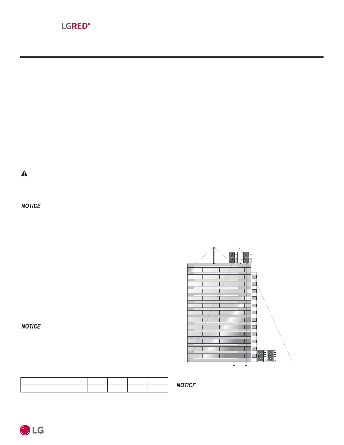
'XHWRRXUSROLF\RIFRQWLQXRXVSURGXFWLQQRYDWLRQVRPHVSHFL¿FDWLRQVPD\FKDQJHZLWKRXWQRWL¿FDWLRQ
©
/*(OHFWURQLFV86$,QF(QJOHZRRG&OLIIV1-$OOULJKWVUHVHUYHG³/*´LVDUHJLVWHUHGWUDGHPDUNRI/*&RUS
63
Piping Limitations and Placement Considerations
MULTI
F
MAX
MULTI
F
WITH
PLACEMENT CONSIDERATIONS
Planning for Snow and Ice
To ensure the outdoor unit operates properly, certain measures are required in locations where there is a possibility of heavy snowfall or
severe windchill or cold:
1. Prepare for severe winter wind chills and heavy snowfall, even in areas of the country where these are unusual phenomena.
2. Position the outdoor unit so that its airflow fans are not buried by direct, heavy snowfall. If snow piles up and blocks the airflow, the
system will malfunction.
3. Remove any snow that has accumulated four (4) inches or more on the top of the outdoor unit.
4. In climates that will experience significant snow buildup, mount the outdoor unit on a raised, field-provided platform or stand. The raised
support platform must be high enough to allow the unit to remain above possible snow drifts, and must be higher than the maximum antici-
pated snowfall for the location.
5. Design the mounting base to prevent snow accumulation on the platform in front or back of the unit frame.
6. Provide a field fabricated snow protection hood to keep snow and ice and/or drifting snow from accumulating on the coil surfaces.
7. To prevent snow and heavy rain from entering the outdoor unit, install the condenser air inlets and outlets facing away from direct winds.
8. Consider tie-down requirements in case of high winds or where required by local codes.
CAUTION
:KHQGHFLGLQJRQDORFDWLRQWRSODFHWKHRXWGRRUXQLWEHVXUHWRFKRRVHDQDUHDZKHUHUXQRIIIURPGHIURVWZLOOQRWDFFXPXODWHDQGIUHH]HRQ
VLGHZDONVRUGULYHZD\VZKLFKZLOOFUHDWHXQVDIHFRQGLWLRQV3URSHUO\LQVWDOODQGLQVXODWHDQ\GUDLQKRVHVWRSUHYHQWWKHKRVHIURPIUHH]LQJFUDFNLQJ
OHDNLQJDQGFDXVLQJXQVDIHFRQGLWLRQVIURPIUR]HQFRQGHQVDWH
&KRRVHDQDUHDZKHUHUXQRIIIURPGHIURVWPRGHZLOOQRWDFFXPXODWHDQGIUHH]HRQVLGHZDONVRUGULYHZD\V3URSHUO\LQVWDOODQGLQVXODWHDQ\GUDLQ
KRVHVWRSUHYHQWWKHKRVHIURPIUHH]LQJFUDFNLQJOHDNLQJDQGGDPDJLQJWKHRXWGRRUXQLW
Tie-Downs, Lightning Protection, and
Wind Protection
Tie-Downs
• The strength of the roof must be checked before installing the
outdoor units.
• The strength of the outdoor unit frames is adequate to be used with
field-provided wind restraint tie-downs.
• If the installation site is prone to high winds or earthquakes, when
installing on the wall or roof, securely anchor the mounting base
using a field-provided tie-down configuration approved by a local
professional engineer.
• The overall tie-down configuration must be approved by a local
professional engineer.
$OZD\VUHIHUWRORFDOFRGHZKHQXVLQJDZLQGUHVWUDLQWV\VWHP
Lightning Protection
• To protect the outdoor unit from lightning, it must be placed within
the specified lightning safety zone.
• Power cable and communication cable must be installed five (5)
feet away from lightning rod.
• A high-resistance ground system must be included to protect
against induced lightning or indirect strike.
Building Height (feet) 66 98 148 197
3URWHFWLRQ$QJOHÜ 55 45 35 25
,IWKHEXLOGLQJGRHVQRWLQFOXGHOLJKWQLQJSURWHFWLRQWKHRXWGRRUXQLWZLOO
EHGDPDJHGIURPDOLJKWQLQJVWULNH,QIRUPWKHFXVWRPHURIWKLVSRVVLELO-
LW\LQDGYDQFH
Ground
Safe zone
Lightning rod
3URWHFWLRQ$QJOHÛaÛ
1.5m
5 feet
Lightning rod
Table 38: 6DIHW\=RQH6SHFL¿FDWLRQV
Figure 44: Lightning Protection Diagram (Outdoor Unit Appearances Dif-
fer According to Model).
6HOHFWLQJWKH%HVW/RFDWLRQIRUWKH2XWGRRU8QLWV
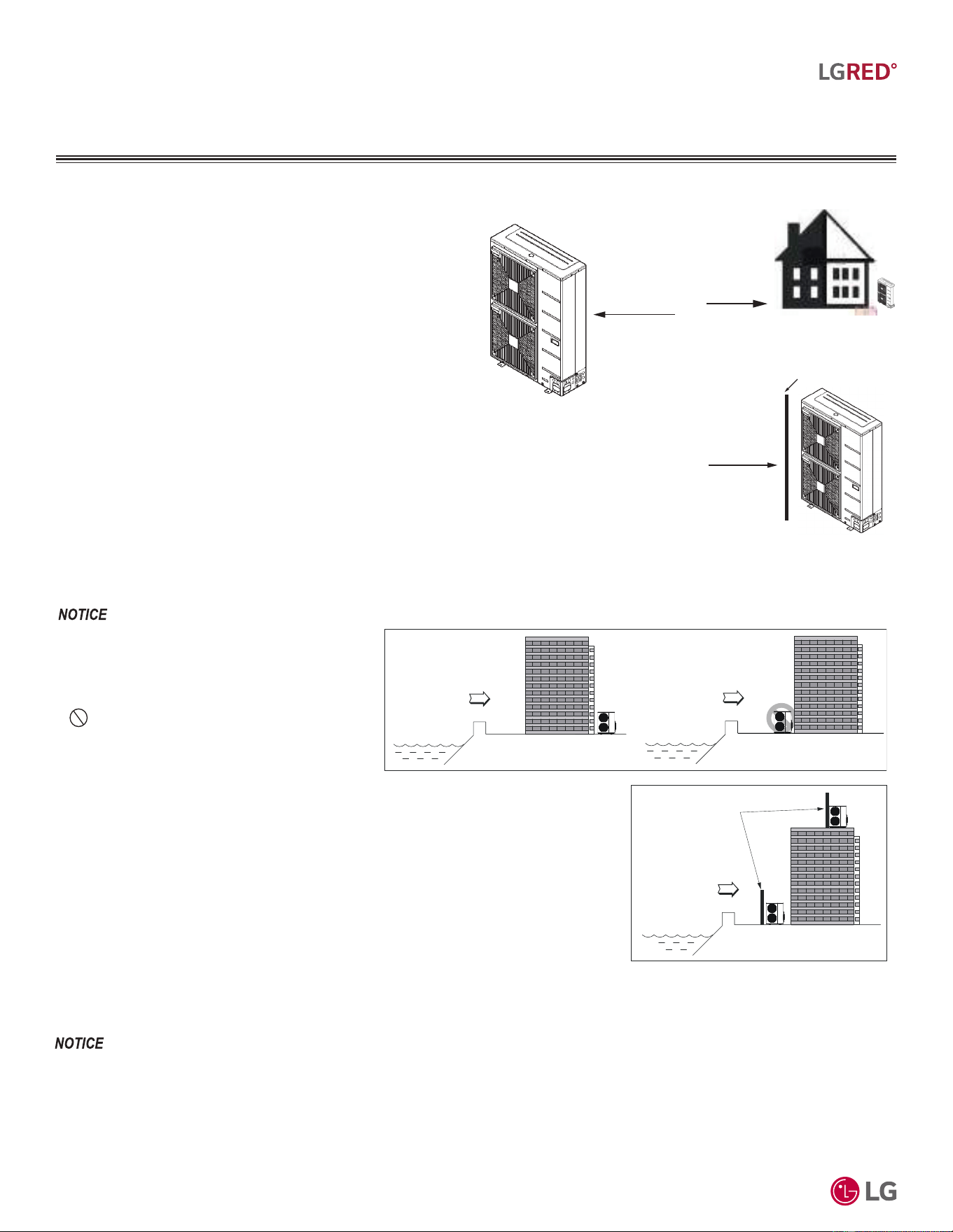
'XHWRRXUSROLF\RIFRQWLQXRXVSURGXFWLQQRYDWLRQVRPHVSHFL¿FDWLRQVPD\FKDQJHZLWKRXWQRWL¿FDWLRQ
©
/*(OHFWURQLFV86$,QF(QJOHZRRG&OLIIV1-$OOULJKWVUHVHUYHG³/*´LVDUHJLVWHUHGWUDGHPDUNRI/*&RUS
64
R32 Multi F and Multi F MAX with LGRED° Outdoor Unit Engineering Manual
MULTI
F
MAX
MULTI
F
WITH
Oceanside Applications
Wind Protection
If the outdoor unit is placed on a roof, position it with the compressor
end (no coil surface) in the direction of the prevailing wind as shown
in the figure at right. In cooler climates, it can be beneficial to posi-
tion the unit in direct sunlight to assist with defrost operations.
If the outdoor unit is not placed on a roof, place it on the leeward
side of the building or in a location where the unit will not be ex-
posed to constant wind.
If placement exposes the unit to constant wind activity, construct a
wind break in front of the unit. Follow the placement guidelines set
forth in “Clearance Requirements”.
$GGLWLRQDODQWLFRUURVLRQWUHDWPHQWZLOOQHHGWREHDSSOLHGWRWKHRXWGRRUXQLWDWRFHDQVLGHORFDWLRQV
2FHDQZLQGVZLOOFDXVHFRUURVLRQSDUWLFXODUO\RQWKH
FRQGHQVHUDQGHYDSRUDWRU¿QVZKLFKLQWXUQFRXOG
FDXVHSURGXFWPDOIXQFWLRQRULQHI¿FLHQWSHUIRUPDQFH
Figure 45: Prevailing Wind Direc-
tion.
Prevailing Winds
Prevailing
Winds
Figure 46: Leeward Side of the
Building.
Prevailing Winds
Wall or Other Wind Break
Figure 47: Wind Break.
Oceanside Application Precautions
Figure 48: Oceanside Placement Using a Building as Shield, and Placement Using a Wind-
break.
• Avoid installing the outdoor unit where it
would be directly exposed to ocean winds.
• Install the outdoor unit on the side of the building
opposite from direct ocean winds.
• Select a location with good drainage.
• Periodically clean dust or salt particles off of the
heat exchanger with water.
If the outdoor unit must be placed in a location
where it would be subjected to direct ocean winds,
install a concrete windbreak strong enough to
block any winds. Windbreaker height and width
must be more than 150% of the outdoor unit, and
be installed at least 14 to 28 inches away from the
outdoor unit to allow for airflow (depending on the
location and outdoor unit size).
Ocean winds
Ocean winds
Ocean winds
Windbreaker
PLACEMENT CONSIDERATIONS
6HOHFWLQJWKH%HVW/RFDWLRQIRUWKH2XWGRRU8QLWV
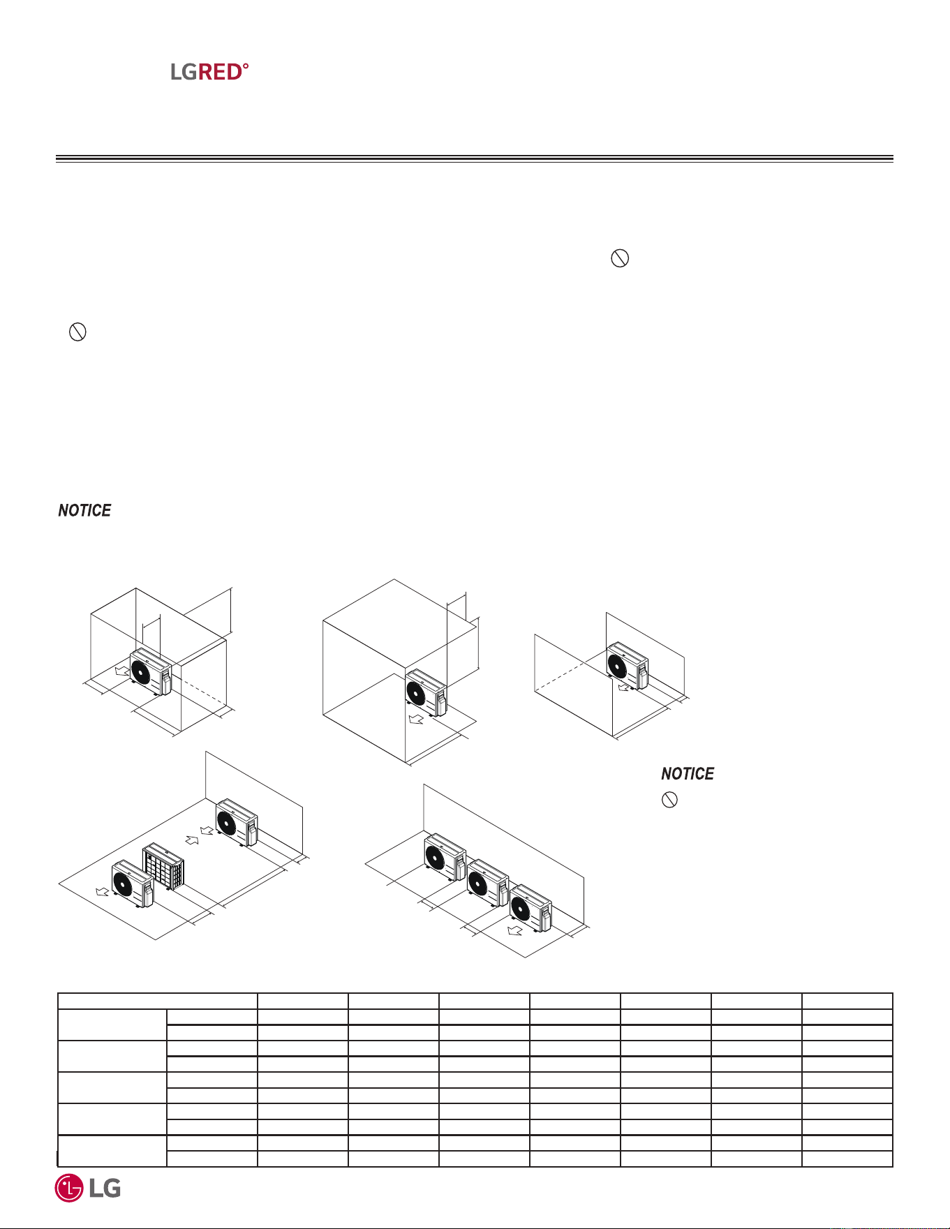
'XHWRRXUSROLF\RIFRQWLQXRXVSURGXFWLQQRYDWLRQVRPHVSHFL¿FDWLRQVPD\FKDQJHZLWKRXWQRWL¿FDWLRQ
©
/*(OHFWURQLFV86$,QF(QJOHZRRG&OLIIV1-$OOULJKWVUHVHUYHG³/*´LVDUHJLVWHUHGWUDGHPDUNRI/*&RUS
65
Piping Limitations and Placement Considerations
MULTI
F
MAX
MULTI
F
WITH
PLACEMENT CONSIDERATIONS
2XWGRRU8QLW&OHDUDQFH5HTXLUHPHQWV
Minimum Allowable Clearance and Service Access Requirements
Proper clearance for the outdoor unit coil is critical for proper unit operation. When installing the outdoor unit, consider service, inlet and
outlet and minimum allowable space requirements as illustrated in the diagrams below and on the following pages.
• Include enough space for airflow and for service access. If installing multiple outdoor units, avoid placing the units where the discharge
of one unit will blow into the inlet side of an adjacent unit.
• If an awning is built over the unit to prevent direct sunlight or rain exposure, make sure that the discharge air of the outdoor unit isn’t
restricted.
• No obstacles to air circulation around the unit; keep proper distances from ceilings, fences, floor, walls, etc. (Install a fence to prevent
pests from damaging the unit or unauthorized individuals from accessing it.)
Minimum Clearance Requirements for Multi F Single Fan Outdoor Units
Specific clearance requirements in the diagram below are for single fan outdoor units. The figure below shows the overall minimum clear-
ances that must be observed for safe operation and adequate airflow around the outdoor unit.
When placing the outdoor unit under an overhang, awning, sunroof or other “roof-like structure”, observe the clearance requirements (as
shown in Cases 1 and 2 for height in relation to the unit.. To have successful service access to the outdoor unit, see the figure below for
minimum spacing. When installing multiple outdoor units, see Cases 4 and 5 for correct spacing requirements.
Figure 49: Single Fan Outdoor Unit Service Access and Allowable Clearances Diagram.
Unit: Inch A B C D E F G
Case 1
Standard 12 24 - 12 - - -
Minimum 4 10 - 4 - - 40
Case 2
Standard - - 20 - - - -
Minimum - - 14 - - - 40
Case 3
Standard - - 20 12 - - -
Minimum - - 14 4 - - -
Case 4
Standard - - - 12 24 - -
Minimum - - - 4 8 79 -
Case 5
Standard - 24 - 12 - - -
Minimum - 10 - 4 - - -
Table 39: Single Fan Outdoor Unit Service Access and Allowable Clearances Diagram Legend.
'RQRWSODFHWKHXQLWZKHUHDQLPDOV
DQGRUSODQWVZLOOEHLQWKHSDWKRIWKH
ZDUPDLURUZKHUHWKHZDUPDLUDQGRU
QRLVHZLOOGLVWXUEQHLJKERUV
,IWKHRXWGRRUXQLWLVLQVWDOOHGEHWZHHQVWDQGDUGDQGPLQLPXPFOHDUDQFHVFDSDFLW\GHFUHDVHVDSSUR[LPDWHO\
A
B
D
G
C
G
C
D
E
D
D
B
B
F
1/16 inch
20 inches or less
Case 1
Case 4
Case 2 Case 3
Case 5
20 inches or less
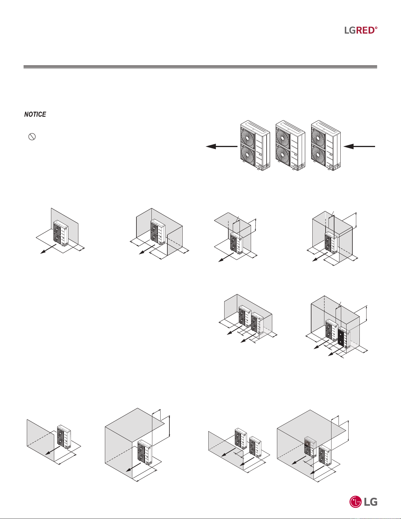
'XHWRRXUSROLF\RIFRQWLQXRXVSURGXFWLQQRYDWLRQVRPHVSHFL¿FDWLRQVPD\FKDQJHZLWKRXWQRWL¿FDWLRQ
©
/*(OHFWURQLFV86$,QF(QJOHZRRG&OLIIV1-$OOULJKWVUHVHUYHG³/*´LVDUHJLVWHUHGWUDGHPDUNRI/*&RUS
66
R32 Multi F and Multi F MAX with LGRED° Outdoor Unit Engineering Manual
MULTI
F
MAX
MULTI
F
WITH
2XWGRRU8QLWV
3/$&(0(17&/($5$1&(
CONSIDERATIONS
Min. 12"
Min. 12"
Min. 24"
Min. 12"
Single Unit—High Rear Wall with
High Side Walls
Single Unit—High Rear Wall
Air
o
w
Air
ow
Figure 50: Improper Outdoor Unit Placement.
Minimum Clearance Requirements for Dual Fan Outdoor Units
Figures below and on the next page illustrate clearance requirements for various installation scenarios for dual fan outdoor units. Use the hot
isle / cold isle approach when placing multiple units in close proximity to each other. Outdoor unit fans draw air from the back of the unit and
discharges out the front. Place units back to back and face to face.
• ,QVWDOODWLRQFOHDUDQFHVPXVWFRPSO\ZLWKORFDOEXLOGLQJFRGHV
• $OOILJXUHVQRWWRVFDOH
•
1HYHUSODFHPXOWLSOHXQLWVIDFLQJEDFNWRIURQWRUIURQWWREDFN
DVVKRZQLPPHGLDWHO\EHORZKHUHRUKLJKDQGORZV\VWHPSUHVVXUH
SUREOHPVZLOORFFXU
Figure 51: Proper Outdoor Unit Placement and Clearances When There Are Obstacles on the Suction Side.
Figure 52: Proper Outdoor Unit Placement and Clearances When There Are Obstacles on the Discharge Side.
Airflow
Airflow
Min. 20"
Max. 20"
Min. 40"
Min. 20"
S
ingle Unit—High Front Wall with
N
o Side Walls
Single Unit—High Front Wall with Building
Overhang and No Side Walls
Air
ow
A
i
r
ow
Min. 40"
Min. 12"
Max. 20"
Max. 20"
Min. 40"
Min. 12"
Min. 24"
Min. 12"
Min. 24"
Min. 24"
Min. 40"
Min. 12"
Max. 20"
Min. 40"
Min. 24"
Min. 24"
Min. 40"
Min. 12"
Single Unit—High Rear Wall with
Building Overhang
Air
ow
Single Unit—High Rear and Side
Walls with Building Overhang
A
ir
o
w
Side by Side—High Rear and
Side Walls
Side by Side—High Rear and Side
Walls with Building Overhang
Air
o
w
A
ir
ow
A
ir
o
w
A
i
r
ow
Min. 40"
Min. 24
"
Max. 20"
Min. 40"
Min. 40"
Min. 24"
Side by Side—High Front Wall with Building
Overhang and No Side or Rear Walls
Side by Side—High Front Wall with
No Side Walls
Air
ow
Air
ow
Ai
r
o
w
A
i
r
o
w
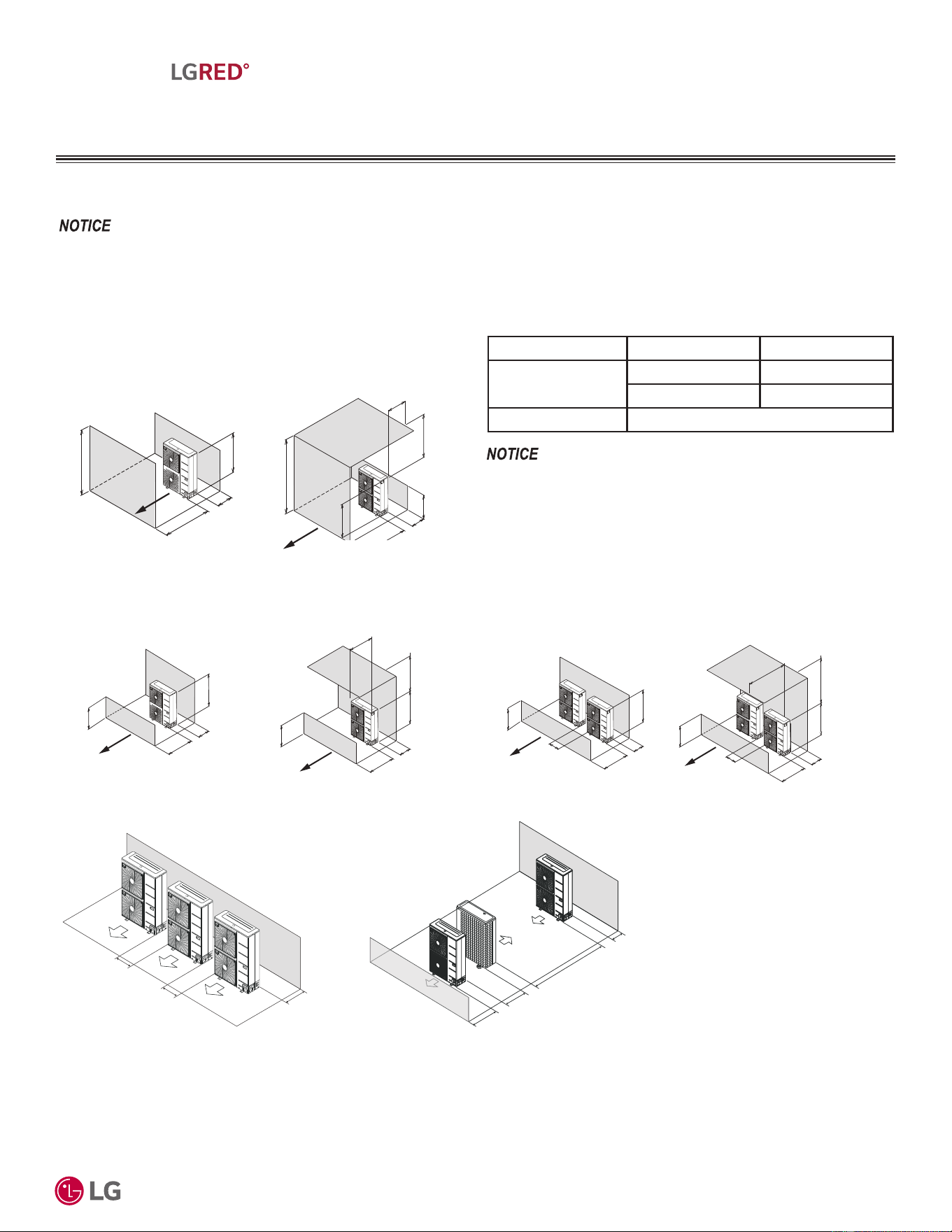
'XHWRRXUSROLF\RIFRQWLQXRXVSURGXFWLQQRYDWLRQVRPHVSHFL¿FDWLRQVPD\FKDQJHZLWKRXWQRWL¿FDWLRQ
©
/*(OHFWURQLFV86$,QF(QJOHZRRG&OLIIV1-$OOULJKWVUHVHUYHG³/*´LVDUHJLVWHUHGWUDGHPDUNRI/*&RUS
67
Piping Limitations and Placement Considerations
MULTI
F
MAX
MULTI
F
WITH
2XWGRRU8QLWV
3/$&(0(17&/($5$1&(
CONSIDERATIONS
H
L
Min. 12"
Max. 20"
Max. 20"
H
L
Min. 40
"
Min. 12
"
Min. 40"
L
L
H
H
Single Unit—High Rear Wall and
Low Front Wall with No Side Walls
A
i
r
ow
Air
ow
Single Unit—High Rear Wall and Low Front Wall
with Building Overhang and No Side Walls
Ls A (Inches)
/+
/V+ 30
1/2 H < Ls 40
H < L 6HW6WDQGDV/+
Figure 53: Proper Outdoor Unit Placement and Clearances When There Are Obstacles on the Suction and the Discharge Sides.
Minimum Clearance Requirements for Dual Fan Outdoor Units, Continued.
When Obstacle Height of the Discharge Side is Higher than the Outdoor Unit.
H
L
Min. 12"
Min. 20"
Min. 40"
Max. 20"
Ls
H
Min. 12"
L
H>LH>L
Single Unit—High Rear and Front Walls
with Building Overhang
Single Unit—High Rear and Front
Walls with No Side Walls
Airow
Air
ow
Obstacle Height of Discharge Side Is Lower than the Outdoor Unit.
H
L
Min. 24"
Min. 12"
Max. 20"
Min. 40"
H
L
Min. 59"
Min. 24
"
2/H<L2/H<L
A
i
r
ow
Air
ow
Min. 59
"
Min. 12"
Side by Side—High Rear Wall and Low Front Wall
with Building Overhang and No Side Walls
Side by Side—High Rear Wall and
Low Front Wall with No Side Walls
Table 40: H, A, and L Ratio.
• ,QVWDOODWLRQFOHDUDQFHVPXVWFRPSO\ZLWKORFDOEXLOGLQJFRGHV
• $OOILJXUHVQRWWRVFDOH
³/´PXVWEHORZHUWKDQ³+´,IDVWDQGLVQHFHVVDU\LWPXVWEHPDGH
RIVROLGPDWHULDOQRWDQRSHQIUDPHWRSUHYHQWWKHGLVFKDUJHDLUIURP
VKRUWF\FOLQJ
Minimum 12
"
Minimum 79"
Minimum 24"
Minimum 40"
Series installation
Series Installation
Minimum 12"
Minimum 24"
Minimum 24"
Side-by-side series installation.

'XHWRRXUSROLF\RIFRQWLQXRXVSURGXFWLQQRYDWLRQVRPHVSHFL¿FDWLRQVPD\FKDQJHZLWKRXWQRWL¿FDWLRQ
©
/*(OHFWURQLFV86$,QF(QJOHZRRG&OLIIV1-$OOULJKWVUHVHUYHG³/*´LVDUHJLVWHUHGWUDGHPDUNRI/*&RUS
68
R32 Multi F and Multi F MAX with LGRED° Outdoor Unit Engineering Manual
MULTI
F
MAX
MULTI
F
WITH
PLACEMENT CONSIDERATIONS
Installing Outdoor Units Indoors
LG Multi F / Multi F MAX outdoor units are engineered to be mounted outdoors and include technology designed to minimize the negative
effects of winter weather’s freezing rain, sleet, and snow. Some building projects, however, necessitate placing the HVAC outdoor units
indoors:
• Lack of ground space.
• Lack of an appropriate outdoor location that meets system design requirements.
• When mounting on the roof is not an option due to a lack of roof space.
• Roof warranty will be voided if mechanical equipment is placed on the membrane.
• On retrofit projects, a former chiller / boiler / air handler equipment room, mechanical area, or penthouse already exists.
• To curtail the potential need for redundant zone heating devices such as wall-fin radiators or duct heaters.
• In extremely cold environments where there is a significant amount of run-time at temperatures well below freezing outside the outdoor unit
ambient air temperature range published in this engineering manual.
Benefits of Installing Outdoor Units Indoors
• Shelters the outdoor unit from direct exposure to prevailing winds that decrease the heating capability of the outdoor unit.
• Protects equipment from freezing precipitation and / or potential ice build-up that could hinder unit operation.
• Maintains coil heat transfer efficiency by reducing the number of and shortening the cycle time for defrost operation.
• Easier maintenance and servicing during inclement weather.
• When mounted in a fully enclosed space, limiting the ambient air temperature could allow the Multi F / Multi F MAX system designer to
eliminate oversizing.
• The outdoor unit to compensate for loss of capacity at low ambient temperatures.
• Can also curtail the need to provide inefficient redundant zone heating devices such as wall-fin radiators and second-stage ancillary heating
devices.
Design Considerations Include:
• Enclosure types and elements such as louvers, rain hoods, dampers and controls, heating methods and sizing of heating devices
• Heating strategies
• Duct design
• Condensate handling
General Guidelines
• Follow ASHRAE 62.1 design guidelines.
• Depending on the project / application, a roof over the outdoor units in combination with a wind break could be all that is necessary.
• Consider the potential for snow accumulation near louvers / roof openings. Outside air intakes and discharge ducts/louvers must be engi-
neered to clear anticipated snow accumulation levels by at least one (1) foot.
• In situations where operation is anticipated at temperatures lower than the product’s minimum operating temperature, ancillary heat must
be provided to heat the outdoor unit coils to ensure continuous compressor operation and heating.
It will be necessary to use an air guide accessory to prevent discharge air from short-cycling back to the coil inlet.
• Consider the direction of prevailing winds and opening placement. If possible, locate inlet openings upwind of discharge openings and other
exhaust outlets.
• When inlet and outlet openings are placed on the same wall, minimum distance between the two openings must be approximately three (3)
feet (minimum distance varies significantly with variations in outlet opening face velocity).
• If roof-mounted ventilation openings are used, strategically locate the inlet ventilation opening(s) upwind of the outlet opening(s).
• Discharge and supply ductwork must be designed to avoid weather related long periods of water entrainment.
,QVWDOOLQJ2XWGRRU8QLWV,QGRRUV
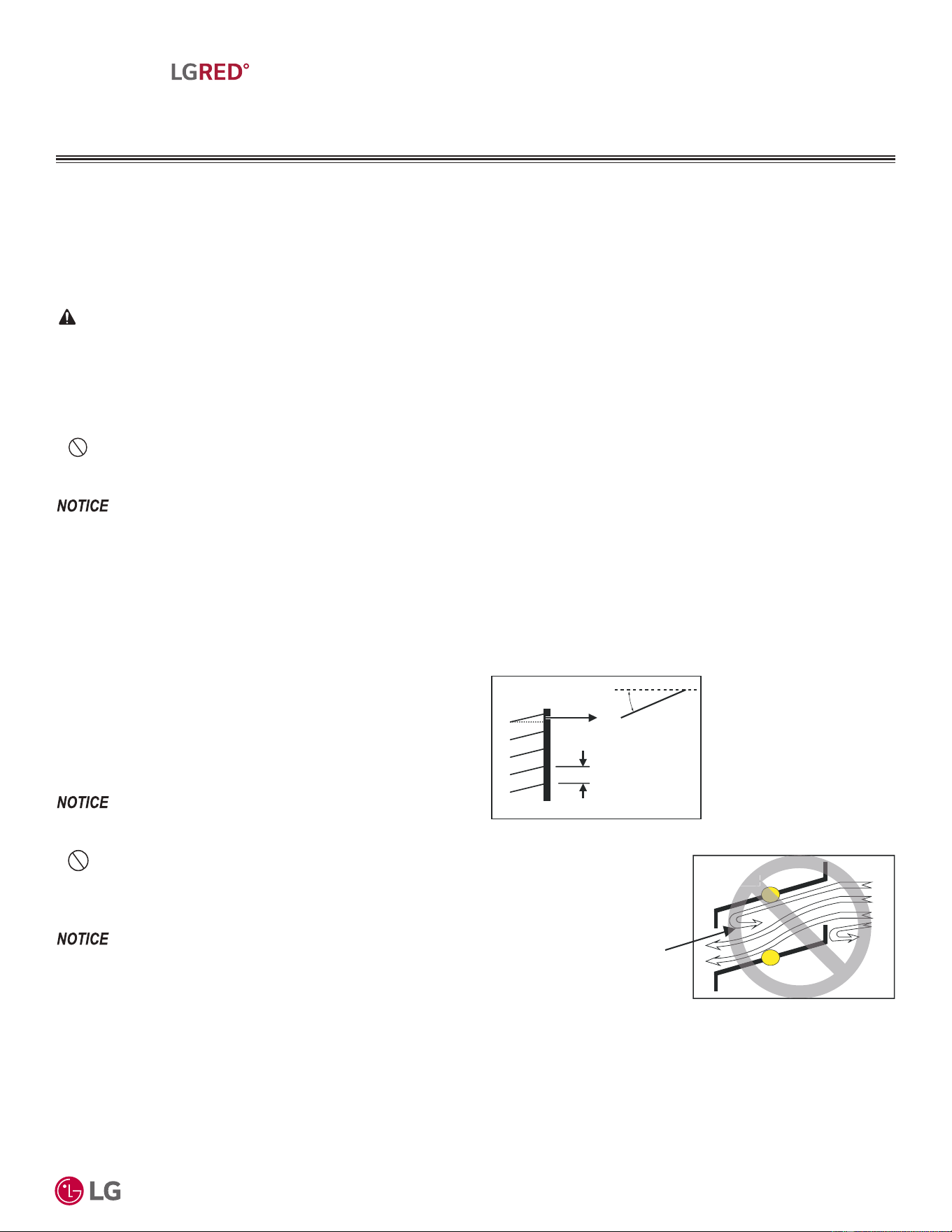
'XHWRRXUSROLF\RIFRQWLQXRXVSURGXFWLQQRYDWLRQVRPHVSHFL¿FDWLRQVPD\FKDQJHZLWKRXWQRWL¿FDWLRQ
©
/*(OHFWURQLFV86$,QF(QJOHZRRG&OLIIV1-$OOULJKWVUHVHUYHG³/*´LVDUHJLVWHUHGWUDGHPDUNRI/*&RUS
69
Piping Limitations and Placement Considerations
MULTI
F
MAX
MULTI
F
WITH
PLACEMENT CONSIDERATIONS
,QVWDOOLQJ2XWGRRU8QLWV,QGRRUV
Provide a means to drain the condensate generated during heating mode and defrost cycle in addition to rainwater that infiltrates the inlet
louver enclosed area.
• Install a field-provided drain pan under the outdoor units and provide a path to a nearby floor drain.
• If the ambient air temperature is expected to drop below 32°F in the enclosure, heat the bottom surface of the pan, drain line, and floor
drain so that the condensate does not freeze before reaching the drain.
Allow for ventilation intake and exhaust air based on maximum outdoor unit fan capacity.
• Select the size, type and orientation of architectural louvers with adequate “net free area” face velocity to ensure the total external static
pressure from the outdoor unit fan does not exceed design limitations (see specification data tables).
•
No obstructions must be placed in front of the louver that could hamper the free flow (throw) of air.
• Roof top openings and / or discharge and supply louvers must be equipped with screens to prevent bird and insect infiltration.
)RUORXYHUUHFRPPHQGDWLRQVVHHEHORZDQGRQWKHQH[WSDJH
As always, the best solution for each project balances acceptable heating performance (considering local weather conditions), capital costs,
life cycle energy consumption, and limitations set forth by local building codes.
:KHQGHFLGLQJRQDORFDWLRQWRSODFHWKHRXWGRRUXQLWEHVXUHWRFKRRVHDQDUHDZKHUHUXQRIIIURPGHIURVWZLOOQRWDFFXPXODWHDQGIUHH]HRQZDON-
ZD\VZKLFKZLOOFUHDWHXQVDIHFRQGLWLRQV
CAUTION
1. Outdoor Unit Enclosure: Manual Door Open Type.
2. Louver Angle: No More Than 15° Horizontally.
3. Space Between Louvers: More than 4 inches (Recommend).
4. Louver Shape: Wing or Plane Type.
Inside
Outside
Air flow passing through
the louver blade backwards
can generate noise.
In
side
Maximum 15°
(Recommended)
More than 4 in.
(Recommended)
Louver
• 2SHQ5DWHDQG,QOHWPXVWEHWDNHQLQWRFRQVLGHUDWLRQZKHQ
GHVLJQLQJWKHORXYHUHGRXWGRRUXQLWHQFORVXUH
• 'RQRWXVH³6´W\SHORXYHUV
If the Louver Open Rate is Too Small
1. 1RLVHFDQRFFXUEHFDXVHRIWKHLQFUHDVHGDLUYHORFLW\SDVVLQJWKURXJK
WKHHORXYHUEODGH
2. 1RLVHFDQRFFXUIURPORXYHUEODGHYLEUDWLRQV
3. $GURSLQRXWGRRUXQLWIDQSHUIRUPDQFHH[FHVVVWDWLFSUHVVXUHFDQ
FDXVHDGURSLQRXWGRRUXQLWSHUIRUPDQFHDQGKHDWH[FKDQJHUHI¿-
FLHQF\
4. ,IWKHORXYHURSHQUDWHLVWRRVPDOORUWKHUHLVLQVXI¿FLHQWDLUÀRZ
H[FKDQJHWKHDLUFRQGLWLRQHUPLJKWVWRSRSHUDWLQJ
Figure 54: Louver Recommendations.
Figure 55: Using “S” Type Louvers.
Louver Recommendations for Outdoor Unit Enclosure
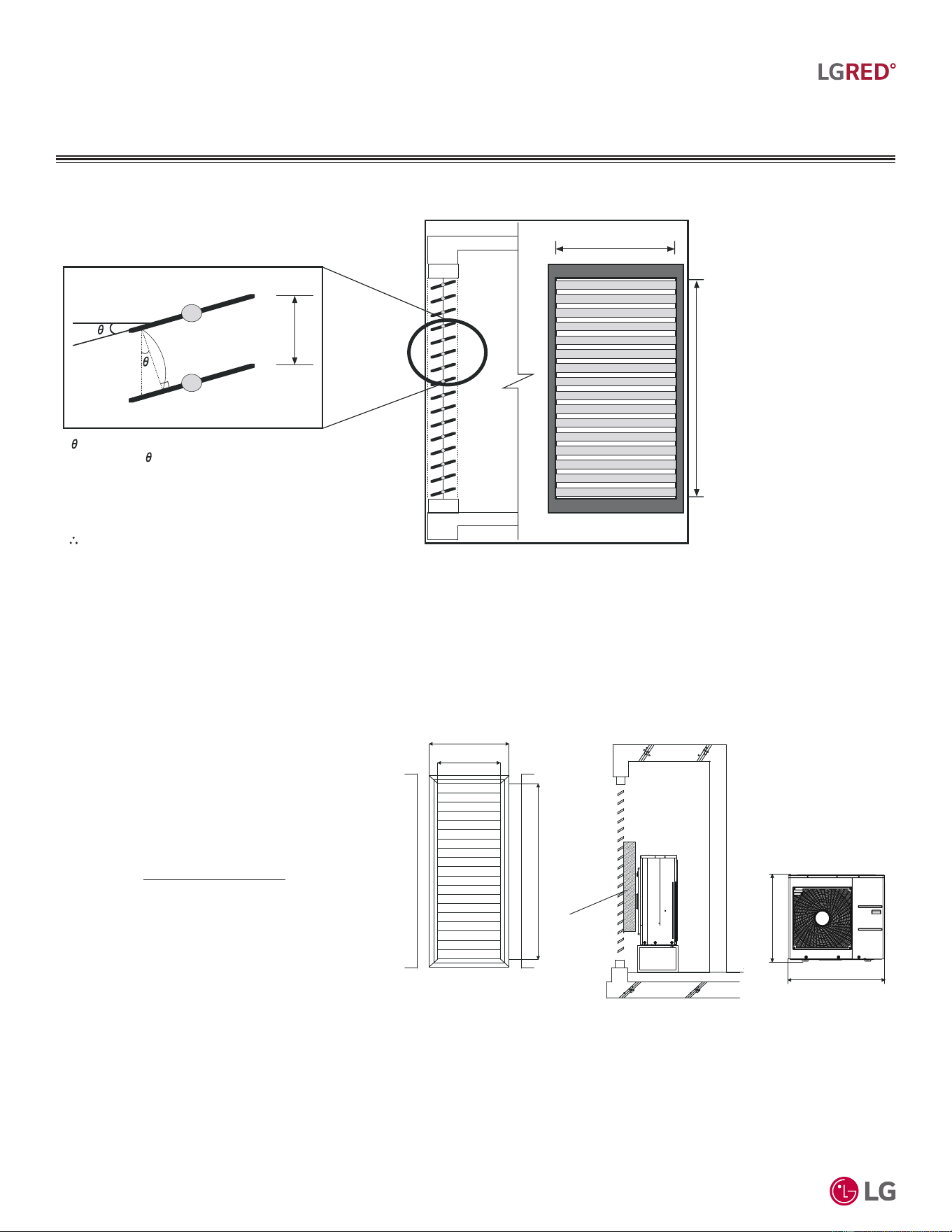
'XHWRRXUSROLF\RIFRQWLQXRXVSURGXFWLQQRYDWLRQVRPHVSHFL¿FDWLRQVPD\FKDQJHZLWKRXWQRWL¿FDWLRQ
©
/*(OHFWURQLFV86$,QF(QJOHZRRG&OLIIV1-$OOULJKWVUHVHUYHG³/*´LVDUHJLVWHUHGWUDGHPDUNRI/*&RUS
70
R32 Multi F and Multi F MAX with LGRED° Outdoor Unit Engineering Manual
MULTI
F
MAX
MULTI
F
WITH
Side View
ho = h * COS
Total Area (A) = H * W
Number of Open Spaces (N) = (Number of Louvers - 1)
Effective Area (Af) = ho * W * N
Louver Open Rate (n) = Af / A
Af = A * n
Effective Cross Section Area
ho
h
W
Front View
H
Open Rate by Louver Radian
Figure 56: Open Rate by Louver Radian Formula.
PLACEMENT CONSIDERATIONS
,QVWDOOLQJ2XWGRRU8QLWV,QGRRUV
55-1/8
47-1/4
37-3/8
74-13/16
32-13/16
Unit: Inch
Air Guide Duct
Louver Dimensions Air Guide Duct on
Outdoor Unit
Outdoor Unit
Dimensions
Formula
• Total Louver Dimension (Excluding Frame) (A) = 3.9 feet x 6.2 feet = 24.2 ft.
2
• Louver Shield Dimension by Product (B) = 3.12 feet x 2.74 feet = 8.55 ft.
2
• Inlet Louver Dimension (A - B) = 15.7 ft.
2
• Equivalent Inlet Dimension (Open Rate 80%) = 15.7 ft
2
x 0.8 = 12.56 ft.
2
• Equivalent Inlet Air Volume = 12.56 ft.
2
x 6.5 ft./s x 60 sec./min. = 4,898 ft.
3
/min.
• Required Air Volume / Equivalent Volume = 4,898 ft.3/min. / 2,295 ft.3/min. = 213% (Within Allowable Limits)
Confirming Air Flow Rate / Total Opening Rate
• Example: KUMXB361A
• Airflow Rate: 2,295 ft.
3
/min.
• Velocity of Outlet Air: 12.9 ft./s
• Velocity of Inlet Air: 6.5 ft./s
• Open Rate = 80% or More
• Discharge Air Guide must be installed.
Figure 57: Example of Installing Outdoor Unit Indoors.
Open Rate = Effective Face Area (Af)
Total Face Area (A)
'XHWRRXUSROLF\RIFRQWLQXRXVSURGXFWLQQRYDWLRQVRPHVSHFL¿FDWLRQVPD\FKDQJHZLWKRXWQRWL¿FDWLRQ
©
/*(OHFWURQLFV86$,QF(QJOHZRRG&OLIIV1-$OOULJKWVUHVHUYHG³/*´LVDUHJLVWHUHGWUDGHPDUNRI/*&RUS
71
Piping Limitations and Placement Considerations
MULTI
F
MAX
MULTI
F
WITH
Selecting the Best Location for the Indoor Units
Dos
6HOHFWDORFDWLRQIRULQVWDOOLQJWKHLQGRRUXQLWVWKDWZLOOPHHWWKHIROORZLQJFRQGLWLRQV
• :LWKLQDOORZDEOHSDUDPHWHUVIRUSURSHUFRQQHFWLRQWRWKHRXWGRRUXQLWRU%UDQFK'LVWULEXWLRQXQLWLID0XOWL)0$;V\VWHP
• 6RWKDWFRQGHQVDWLRQGUDLQDJHFDQEHFRQYHQLHQWO\URXWHGDZD\
• ,QFOXGHHQRXJKVSDFHDURXQGWKHLQGRRUXQLWVRWKDWLWLVDFFHVVLEOHIRUPDLQWHQDQFHDQGVHUYLFHSXUSRVHV
• :KHUHHOHFWULFDOQRLVHHOHFWURPDJQHWLFZDYHVZLOOQRWDIIHFWLQGRRUXQLWRSHUDWLRQ0DLQWDLQSURSHUGLVWDQFHVEHWZHHQWKHLQGRRUXQLWVDQG
HOHFWULFZLUHVDXGLRDQGYLVXDODSSOLDQFHVEUHDNHUFLUFXLWSDQHOVHWF,IWKHIUHTXHQF\VLJQDORIWKHDSSOLDQFHLVXQVWDEOHWKHQLQVWDOOWKH
LQGRRUXQLWDPLQLPXPRIWHQIHHWDZD\DQGUXQWKHSRZHUDQGWUDQVPLVVLRQFDEOHVWKURXJKDFRQGXLW
• $QDUHDWKDWLVOHYHODQGZLWKHQRXJKVWUHQJWKWREHDUWKHZHLJKWRIWKHLQGRRUXQLWV
Do Not’s
• :KHUHWKHUHDUHQRREVWDFOHVWRDLUFLUFXODWLRQDURXQGWKHXQLWNHHSSURSHUGLVWDQFHVIURPFHLOLQJVGRRUZD\VIORRUZDOOVHWF
• $QDUHDZKHUHRSHUDWLRQVRXQGZRQ¶WGLVWXUERFFXSDQWV
• $QDUHDWKDWGRHVQRWH[SRVHWKHLQGRRUXQLWVWRKHDWZDWHUVWHDPRLOVSODWWHULQJRUVSUD\
Selecting the Best Location for the Branch Distribution (BD) Unit
Dos
%UDQFK'LVWULEXWLRQ%'XQLWVDUHXVHGRQO\ZLWK0XOWL)0$;V\VWHPVWRGLVWULEXWHWKHUHIULJHUDQWIURPWKHRXWGRRUXQLWWRXSWRHLJKWLQGRRU
XQLWV6HOHFWORFDWLRQLQGRRUVWKDWZLOOPHHWWKHIROORZLQJFRQGLWLRQV
• :LWKLQDOORZDEOHSDUDPHWHUVIRUSURSHUFRQQHFWLRQWRWKH0XOWL)0$;RXWGRRUXQLWDQGLQGRRUXQLWVUHIULJHUDQWSLSLQJDQGZLUHOHQJWKV
PXVWQRWH[FHHGDPRXQWVVSHFLILHGE\/*(OHFWURQLFV86$,QF
• &RQGHQVDWHGUDLQSLSLQJLVQRWUHTXLUHG
• (QVXUHWKHUHLVHQRXJKVSDFHLQWKHLQVWDOODWLRQDUHDIRUVHUYLFHSXUSRVHVPLQLPXPLQFKHVLQVWDOOWKHUHIULJHUDQWSLSLQJDQGHOHFWULFDO
ZLULQJV\VWHPLQDQHDVLO\DFFHVVLEOHORFDWLRQ
• /HYHOZKHUHWKHUHLVHQRXJKVWUHQJWKWREHDUWKHZHLJKWRIWKHEUDQFKGLVWULEXWLRQXQLW
Do Not’s
• ,QVWDOOWKHEUDQFKGLVWULEXWLRQXQLWLQDORFDWLRQZKHUHLWZRXOGEHVXEMHFWHGWRVWURQJUDGLDWLRQKHDWIURPKHDWVRXUFHV
• ,QVWDOOLQDQLQVWDOODWLRQHQYLURQPHQWZKHUHWKHEUDQFKGLVWULEXWLRQXQLWZRXOGEHH[SRVHGWRKHDWZDWHUVWHDPRLOVSODWWHULQJRUVSUD\
• ,QVWDOOWKHXQLWLQDORFDWLRQZKHUHDQ\VRXQGLWJHQHUDWHVZLOOGLVWXUERFFXSDQWVLQWKHVXUURXQGLQJURRPV
• 1RREVWDFOHVWRDLUFLUFXODWLRQDURXQGWKHXQLWNHHSSURSHUGLVWDQFHVIURPFHLOLQJVGRRUZD\VIORRUZDOOVHWF
• ,QVWDOOLQDQDUHDZKHUHKLJKIUHTXHQF\HOHFWULFDOQRLVHHOHFWURPDJQHWLFZDYHVZLOODIIHFWRSHUDWLRQ0DLQWDLQSURSHUGLVWDQFHVEHWZHHQWKH
EUDQFKGLVWULEXWLRQXQLWVDQGHOHFWULFZLUHVDXGLRDQGYLVXDODSSOLDQFHVEUHDNHUFLUFXLWSDQHOVHWF
6HOHFWLQJWKH%HVW/RFDWLRQIRUWKH,QGRRU8QLWV
%UDQFK'LVWULEXWLRQ8QLWV
,QGRRUXQLWV,'8VPXVWQRWEHSODFHGLQDQHQYLURQPHQWZKHUHWKHLQGRRUXQLWVZLOOEHH[SRVHGWRKDUPIXOYRODWLOHRUJDQLFFRPSRXQGV92&V
RULQHQYLURQPHQWVZKHUHWKHUHLVLPSURSHUDLUPDNHXSRUVXSSO\RULQDGHTXDWHYHQWLODWLRQ,IWKHUHDUHFRQFHUQVDERXW92&VLQWKHHQYLURQPHQW
ZKHUHWKH,'8VDUHLQVWDOOHGSURSHUDLUPDNHXSRUVXSSO\DQGRUDGHTXDWHYHQWLODWLRQPXVWEHSURYLGHG$GGLWLRQDOO\LQEXLOGLQJVZKHUH,'8VZLOO
EHH[SRVHGWR92&VFRQVLGHUDIDFWRU\DSSOLHGHSR[\FRDWLQJWRWKHIDQFRLOVIRUHDFKLQGRRUXQLW
)RUGHWDLOHGSODFHPHQWFRQVLGHUDWLRQVDQGLQVWDOODWLRQUHTXLUHPHQWVIRULQGRRUXQLWVUHIHUWRLWV,QGRRU8QLW(QJLQHHULQJDQG
or Installation Manuals.
PLACEMENT CONSIDERATIONS
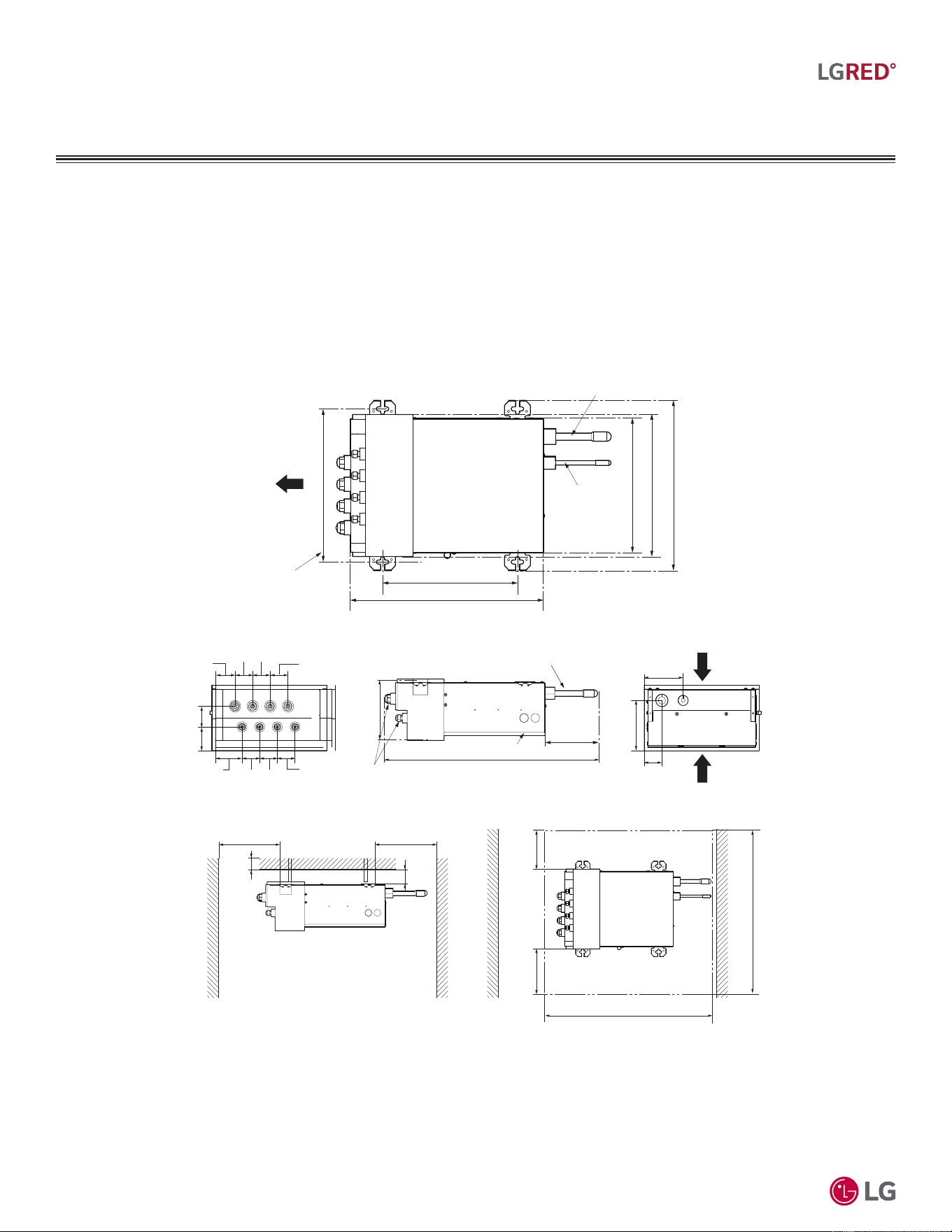
'XHWRRXUSROLF\RIFRQWLQXRXVSURGXFWLQQRYDWLRQVRPHVSHFL¿FDWLRQVPD\FKDQJHZLWKRXWQRWL¿FDWLRQ
©
/*(OHFWURQLFV86$,QF(QJOHZRRG&OLIIV1-$OOULJKWVUHVHUYHG³/*´LVDUHJLVWHUHGWUDGHPDUNRI/*&RUS
72
R32 Multi F and Multi F MAX with LGRED° Outdoor Unit Engineering Manual
MULTI
F
MAX
MULTI
F
WITH
6HOHFWLQJWKH%HVW/RFDWLRQIRUWKH,QGRRU8QLWV
%UDQFK'LVWULEXWLRQ8QLWV
PLACEMENT CONSIDERATIONS
Branch Distribution Unit Orientation
Multi F MAX branch distribution units can be installed in a multitude of options to fit various building configurations and job or application
requirements. The installation location of the PCB within the branch distribution unit can be changed for easier service access, depending
on the branch distribution unit installation itself. Multi F MAX branch distribution units include electronic expansion valves that properly seat
only if the branch distribution unit is installed in an acceptable orientation. Installations with improper branch distribution unit orientation risk
incomplete valve seating and system performance degradation from potential refrigerant leakage through the electronic expansion valve. See
the Branch Distribution Product Section for acceptable installation options.
Figure 58: Branch Distribution Unit Components and Clearances.
Branch Distribution Unit Installation
• Branch distribution units may be installed suspended from the ceiling, mounted on the wall, horizontally, or vertically. See below and the
Branch Distribution Unit Product Section for details.
• Direction A indicates piping for the indoor units.
• Leave a two (2) foot square opening for clearance and service as shown below for both suspended from the ceiling and mounted on the
wall installation. See Sides B and C for service sides.
• Side B (indicates top of the unit facing up) must be within ±5° forward, backward, or to the sides.
• This unit “does not require drain treatment” as it includes an internal foam for the low-pressure piping insulation.
Min. 15-3/4 (400)
Min. 1-3/16
(30)
Min.
3-15/16
(100)
Min. 15-3/4 (400)
Branch Pipe
25-3/8 (644)
6-7/16 (162.7)
Control Cover
Main Pipe
(Service Space)
Clearance Space
Min. 11-13/16
(300)
35-7/16 (900)
Min. 35-7/16 (900)
13-55/64 (352)
Ø3/4 (19.05)
Ø3/8 (9.52)
Suspension Bolt Pitch
6-5/16 (160)
12-1/2 (317)
17-1/4 (438.8)
15-7/16 (392)
12-1/8 (308.5)
12-53/64 (326)
A
B
C
5-1/2 (140)
2-1/64 (51)
4-3/8 (111)
2-3/16 (55)
1-15/16 (50)
2-63/64 (76)
2-1/4 (57)
2-5/8 (66)
Unit: Inch (mm)
1-15/16 (50)
1-15/16 (50)
1-15/16 (50) 1-15/16 (50)
1-15/16 (50)
Min. 11-13/16
(300)
Piping to
Indoor
Units
Service Direction
Service Direction

'XHWRRXUSROLF\RIFRQWLQXRXVSURGXFWLQQRYDWLRQVRPHVSHFL¿FDWLRQVPD\FKDQJHZLWKRXWQRWL¿FDWLRQ
©
/*(OHFWURQLFV86$,QF(QJOHZRRG&OLIIV1-$OOULJKWVUHVHUYHG³/*´LVDUHJLVWHUHGWUDGHPDUNRI/*&RUS
73
Piping Limitations and Placement Considerations
MULTI
F
MAX
MULTI
F
WITH
LIMITED WARRANTY (USA)
The product’s full Limited Warranty terms and conditions and arbitration
UHTXLUHPHQWVDUHDYDLODEOHDWKWWSVZZZOJKYDFFRP
LG Electronics, U.S.A., Inc.
Air Conditioning Technologies
4300 North Point Parkway
Alpharetta, Georgia 30022
www.lghvac.com
New Issue: EM_Multi_F-MAX_LGRED_ODU_R32_12_24
