
INSTALLATION MANUAL
Standard Inverter
AIR
CONDITIONER
Please read this installation manual completely before installing the product.
Installation work must be performed in accordance with the national wiring
standards by authorized personnel only.
Please retain this installation manual for future reference after reading it
thoroughly.
www.lghvac.com
www.lg.com
Copyright © 2024-2025 LG Electronics Inc. All Rights Reserved.
MFL63260140
Rev.04_062425
ENGLISH
FRANÇAIS
ESPAÑOL

• Do not cool excessively indoors. This may be harmful for your health and may consume
more electricity.
• Block sunlight with blinds or curtains while you are operating the air conditioner.
• Keep doors or windows closed tightly while you are operating the air conditioner.
• Adjust the direction of the air flow vertically or horizontally to circulate indoor air.
• Speed up the fan to cool or warm indoor air quickly, in a short period of time.
• Open windows regularly for ventilation as the indoor air quality may deteriorate if the air
conditioner is used for many hours.
• Clean the air filter once every 2 weeks. Dust and impurities collected in the air filter may
block the air flow or weaken the cooling / dehumidifying functions.
For your records
Staple your receipt to this page in case you need it to prove the date of purchase or for
warranty purposes.
Write the model number and the serial number here:
Model number :
Serial number :
You can find them on a label on the side of each unit.
Dealer’s name :
Date of purchase :
Here are some tips that will help you minimize the power consumption when you use the air
conditioner.
You can use your air conditioner more efficiently by referring to the instructions below:
TIPS FOR SAVING ENERGY
ENGLISH
2
TIPS FOR SAVING ENERGY
WARNING
• Installation or repairs made by unqualified persons can result in hazards to you and others.
• Installation of all field wiring and components MUST conform with local building codes or, in the
absence of local codes, with the National Electrical Code 70 and the National Building Construction
and Safety Code or Canadian Electrical code and National Building Code of Canada.
• The information contained in the manual is intended for use by a qualified service technician familiar
with safety procedures and equipped with the proper tools and test instruments.
• Failure to carefully read and follow all instructions in this manual can result in equipment malfunction,
property damage, personal injury and/or death.
Installation
• Always perform grounding.
- Otherwise, it may cause electrical shock.
• Don’t use a power cord, a plug or a loose socket which is damaged.
- Otherwise, it may cause a fire or electrical shock.
• For installation of the product, always contact the service center or a professional installation agency.
- Otherwise, it may cause a fire, electrical shock, explosion or injury.
• Securely attach the electrical part cover to the indoor unit and the service panel to the outdoor unit.
- If the electrical part cover of the indoor unit and the service panel of the outdoor unit are not
attached securely, it could result in a fire or electric shock due to dust, water, etc.
• Always install an air leakage breaker and a dedicated switching board.
- No installation may cause a fire and electrical shock.
!
ENGLISH
SAFETY INSTRUCTIONS
3
The following safety guidelines are intended to prevent unforeseen risks or damage from unsafe or
incorrect operation of the appliance. The guidelines are separated into ‘WARNING’ and ‘CAUTION’ as
described below.
SAFETY INSTRUCTIONS
WARNING
This indicates that the failure to follow the instructions can cause serious injury or death.
CAUTION
This indicates that the failure to follow the instructions can cause the minor injury or damage to the
product.
This symbol is displayed to indicate matters and operations that can cause risk.
Read the part with this symbol carefully and follow the instructions in order to avoid risk.
!
!
!
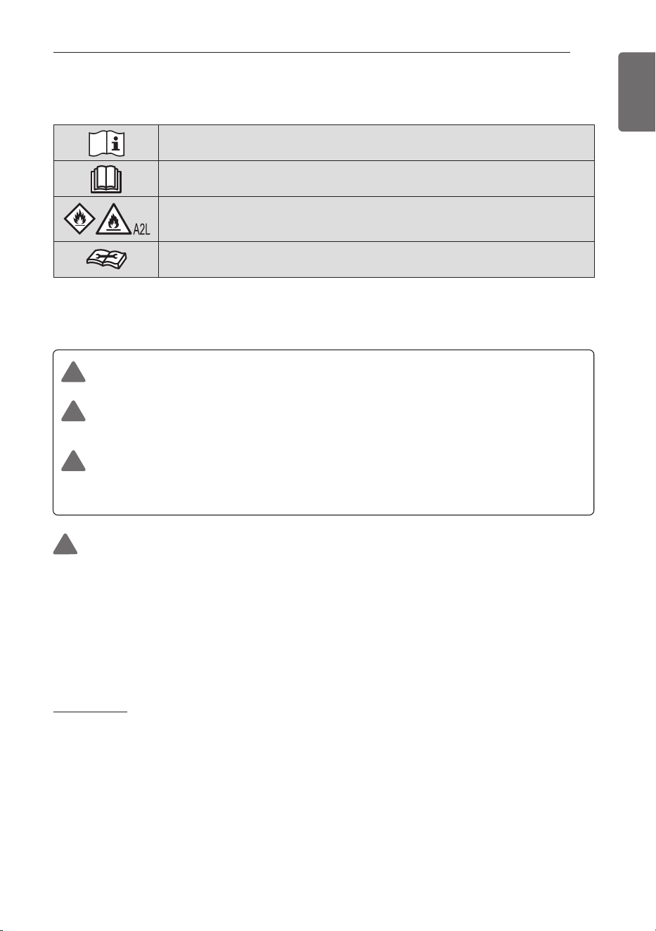
Read the precautions in this manual carefully before operating the unit.
This symbol indicates that the Operation Manual should be read carefully.
This appliance is filled with flammable refrigerant.
This symbol indicates that a service personnel should be handling this
equipment with reference to the Installation Manual.

• Do not keep or use flammable gases or combustibles near the air conditioner.
- Otherwise, it may cause a fire or the failure of product.
• Ensure that an installation frame of the outdoor unit is not damaged due to use for a long time.
- It may cause injury or an accident.
• Do not disassemble or repair the product randomly.
- It will cause a fire or electrical shock.
• Do not install the product at a place that there is concern of falling down.
- Otherwise, it may result in personal injury.
• Use caution when unpacking and installing.
- Sharp edges may cause injury.
• Use a vacuum pump or Inert (nitrogen) gas when doing leakage test or air purge. Do not compress
air or Oxygen and Do not use Flammable gases. Otherwise, it may cause fire or explosion. There is
the risk of death, injury, fire or explosion.
• Do not store or use flammable gas or combustibles near the unit.
- There is risk of fire, explosion, and physical injury or death.
For add on heat pumps with flammable refrigerants
1. Instruction for installation of the critical-to-safety wiring connection of the leak detection sensor or
leak detection system to the furnace assembly.
- The wiring shall be not less than 18 AWG with a minimum insulation thickness of 1.58 mm or
protected from damage. Critical-to-safety wiring is any field installed wiring necessary to fulfill the
requirements of flammable refrigerant in the event of detection of a leak.
2. Shall not be installed on furnaces with an inductive electrical greater than Le
- Le = 5 when breaking alll phases of a three phase load
- Le = 2.5 all others
3. Detection of a leak shall turn on the indoor fan at the highest available speed or turn it on to not less
minimum air flow rate (Consult furnace manufacturer.)
• Do not use means to accelerate the defrosting process or to clean, other than those recommended
by the manufacturer.
• The appliance shall be stored in a room without continuously operating ignition sources (for example:
open flames, an operating gas appliance or an operating electric heater.)
• Do not pierce or burn.
• Be aware that refrigerants may not contain an odour.
• The manufacturer may provide other suitable examples or may provide additional information about
the refrigerant odour.
• Pipe-work including piping material, pipe routing, and installation shall include protection from
physical damage in operation and service, and be in compliance with national and local codes and
standards, such as ASHRAE 15, ASHRAE 15.2, IAPMO Uniform Mechanical Code, ICC International
Mechanical Code, or CSA B52. All field joints shall be accessible for inspection prior to being covered
or enclosed.
• An unventilated area where the appliance using flammable refrigerants is installed shall be so
constructed that should any refrigerant leak, it will not stagnate so as to create a fire or explosion
hazard.
• Field-made refrigerant joints indoors shall be tightness tested. The test method shall have a
sensitivity of 5 grams per year of refrigerant or better under a pressure of at least 0,25 times the
maximum allowable pressure. No leak shall be detected;
• If appliances connected via an air duct system to one or more rooms with A2L REFRIGERANTS are
installed in a room with an area less than Amin as determined in standard, that room shall be without
continuously operating open flames (e.g. an operating gas appliance) or other POTENTIAL IGNITION
SOURCES (for e.g., an operating electric heater, hot surfaces). A flame-producing device may be
installed in the same space if the device is provided with an effective flame arrest.
ENGLISH
4
SAFETY INSTRUCTIONS

ENGLISH
• After completion of field piping for split systems, the field pipework shall be pressure tested with an
inert gas and then vacuum tested prior to refrigerant charging, according to the following
requirements:
- The minimum test pressure for the low side of the system shall be the low side design pressure and
the minimum test pressure for the high side of the system shall be the high side design pressure,
unless the high side of the system, cannot be isolated from the low side of the system in which case
the entire system shall be pressure tested to the low side design pressure.
- The test pressure after removal of pressure source shall be maintained for at least 1 h with no
decrease of pressure indicated by the test gauge, with test gauge resolution not exceeding 5% of the
test pressure.
- During the evacuation test, after achieving a vacuum level specified in the manual or less, the
refrigeration system shall be isolated from the vacuum pump and the pressure shall not rise above
1500 microns within 10 min. The vacuum pressure level shall be specified in the manual, and shall be
the lessor of 500 microns or the value required for compliance with national and local codes and
standards, which may vary between residential, commercial, and industrial buildings.
• Refrigerant tubing shall be protected or enclosed to avoid damage.
• Flexible refrigerant connectors (such as connecting lines between the indoor and outdoor unit) that
may be displaced during normal operations shall be protected against mechanical damage.
• A brazed, welded, or mechanical connection shall be made before opening the valves to permit
refrigerant to flow between the refrigerating system parts.
• Keep any required ventilation openings clear of obstruction.
• Mechanical connections (mechanical connectors or flared joints) shall be accessible for maintenance
purposes
• Flexible pipe elements shall be protected against mechanical damage, excessive stress by torsion, or
other forces. They should be checked for mechanical damage annually.
• Protection devices, piping and fittings shall be protected as far as possible against adverse
environmental effects, for example, the danger of water collecting and freezing in relief pipes or the
accumulation of dirt and debris.
• Precautions shall be taken to avoid excessive vibration or pulsation to refrigerating piping.
• Piping in refrigerating systems shall be so designed and installed to minimize the likelihood hydraulic
shock damaging the system.
• Provision shall be made for expansion and contraction of long runs of piping.
• Steel pipes and components shall be protected against corrosion with a rustproof coating before
applying any insulation.
• Auxiliary devices which can be potential ignition source shall not be installed in connecting ductwork.
Examples of potential ignition sources are UV lights, electric heaters with a temperature exceeding
700 °C, pilot flames, brushed motors and similar devices.
SAFETY INSTRUCTIONS
5
Qualification of workers
The manual shall contain specific information about the required qualification of the working personnel for
maintenance, service and repair operations.
Every working procedure that affects safety means shall only be carried out by qualified person by
manufacturer.
Examples for such working procedures are:
- Breaking into the refrigerating circuit;
- Opening of sealed components;
- Opening of ventilated enclosures.

ENGLISH
6
SAFETY INSTRUCTIONS
Operation
• Do not share the outlet with other appliances.
- It will cause an electric shock or a fire due to heat generation.
• Do not use the damaged power cord.
- Otherwise, it may cause a fire or electrical shock.
• Do not modify or extend the power cord randomly.
- Otherwise, it may cause a fire or electrical shock.
• Take care so that the power cord may not be pulled during operation.
- Otherwise, it may cause a fire or electrical shock.
• Unplug the unit if strange sounds, smell, or smoke comes from it.
- Otherwise, it may cause electrical shock or a fire.
• Keep the flames away.
- Otherwise, it may cause a fire.
• Take the power plug out if necessary, holding the head of the plug and do not touch it with wet hands.
- Otherwise, it may cause a fire or electrical shock.
• Do not use the power cord near the heating tools.
- Otherwise, it may cause a fire and electrical shock.
• Do not open the suction inlet of the indoor/outdoor unit during operation.
- Otherwise, it may electrical shock and failure.
• Do not allow water to run into electrical parts.
- Otherwise, it may cause the failure of machine or electrical shock.
• Hold the plug by the head when taking it out.
- It may cause electric shock and damage.
• Never touch the metal parts of the unit when removing the filter.
- They are sharp and may cause injury.
• Do not step on the indoor/outdoor unit and do not put anything on it.
- It may cause an injury through dropping of the unit or falling down.
• Do not place a heavy object on the power cord.
- Otherwise, it may cause a fire or electrical shock.
• When the product is submerged into water, always contact the service center.
- Otherwise, it may cause a fire or electrical shock.
• Take care so that children may not step on the outdoor unit.
- Otherwise, children may be seriously injured due to falling down.
• The appliance shall be stored so as to prevent mechanical damage from occurring.
• This appliance is not intended for use by persons (including children) with reduced physical, sensory
or mental capabilities or lack of experience and knowledge, unless they have been given supervision
or instruction concerning use of the appliance by a person responsible for their safety. Children
should be supervised to ensure that they do not play with the appliance.
• LEAK DETECTION SYSTEM installed. Unit must be powered except for service. This unit is
equipped with a refrigerant leak detector for safety. To be effective, the unit must be electrically
powered at all times after installation, other than when servicing.
• The appliance shall be installed in accordance with national wiring regulations.
• Means for disconnection must be incorporated in the fixed wiring in accordance with the wiring rules.
• If the supply cord is damaged, it must be replaced by the manufacturer, its service agent or similarly
qualified persons in order to avoid a hazard.

ENGLISH
SAFETY INSTRUCTIONS
7
Service & Installation
Checks to the area
Prior to beginning work on systems containing flammable refrigerants, safety checks are necessary to
ensure that the risk of ignition is minimised. For repair to the refrigerating system, the following
precautions shall be complied with prior to conducting work on the system.
Work procedure
Work shall be undertaken under a controlled procedure so as to minimise the risk of a flammable gas
or vapour being present while the work is being performed.
General work area
All maintenance staff and others working in the local area shall be instructed on the nature of work
being carried out. Work in confined spaces shall be avoided.
Checking for presence of refrigerant
The area shall be checked with an appropriate refrigerant detector prior to and during work, to ensure
the technician is aware of potentially flammable atmospheres. Ensure that the leak detection
equipment being used is suitable for use with flammable refrigerants, i.e. non-sparking, adequately
sealed or intrinsically safe.
Presence of fire extinguisher
If any hot work is to be conducted on the refrigerating equipment or any associated parts, appropriate
fire extinguishing equipment shall be available to hand. Have a dry powder or CO2 fire extinguisher
adjacent to the charging area.
No ignition sources
No person carrying out work in relation to a refrigerating system which involves exposing any pipe work
shall use any sources of ignition in such a manner that it may lead to the risk of fire or explosion.
All possible ignition sources, including cigarette smoking, should be kept sufficiently far away from the
site of installation, repairing, removing and disposal, during which refrigerant can possibly be released
to the surrounding space. Prior to work taking place, the area around the equipment is to be surveyed
to make sure that there are no flammable hazards or ignition risks. “No Smoking” signs shall be
displayed.
Ventilated area
Ensure that the area is in the open or that it is adequately ventilated before breaking into the system or
conducting any hot work. A degree of ventilation shall continue during the period that the work is
carried out.
The ventilation should safely disperse any released refrigerant and preferably expel it externally into
the atmosphere.
Checks to the refrigerating equipment
Where electrical components are being changed, they shall be fit for the purpose and to the correct
specification.
At all times the manufacturer’s maintenance and service guidelines shall be followed. If in doubt
consult the manufacturer’s technical department for assistance.
The following checks shall be applied to installations using flammable refrigerants:
- The actual refrigerant charge is in accordance with the room size within which the refrigerant
containing parts are installed
- The ventilation machinery and outlets are operating adequately and are not obstructed

ENGLISH
8
SAFETY INSTRUCTIONS
- If an indirect refrigerating circuit is being used, the secondary circuit shall be checked for the
presence of refrigerant
- Marking to the equipment continues to be visible and legible. Markings and signs that are illegible
shall be corrected
- Refrigerating pipe or components are installed in a position where they are unlikely to be exposed to
any substance which may corrode refrigerant containing components, unless the components are
constructed of materials which are inherently resistant to being corroded or are suitably protected
against being so corroded.
Checks to electrical devices
Repair and maintenance to electrical components shall include initial safety checks and component
inspection procedures. If a fault exists that could compromise safety, then no electrical supply shall be
connected to the circuit until it is satisfactorily dealt with. If the fault cannot be corrected immediately
but it is necessary to continue operation, an adequate temporary solution shall be used. This shall be
reported to the owner of the equipment so all parties are advised.
Initial safety checks shall include:
- Capacitors are discharged: this shall be done in a safe manner to avoid possibility of sparking.
- No live electrical components and wiring are exposed while charging, recovering or purging the
system.
- Continuity of earth bonding
Repairs to sealed components
Sealed electrical components shall be replaced.
Repair to intrinsically safe components
Intrinsically safe components must be replaced.
Cabling
Check that cabling will not be subject to wear, corrosion, excessive pressure, vibration, sharp edges or
any other adverse environmental effects. The check shall also take into account the effects of aging or
continual vibration from sources such as compressors or fans.
Detection of flammable refrigerants
Under no circumstances shall potential sources of ignition be used in the searching for or detection of
refrigerant leaks. A halide torch (or any other detector using a naked flame) shall not be used.
Leak detection methods
The following leak detection methods are deemed acceptable for all refrigerant systems.
Electronic leak detectors may be used to detect refrigerant leaks but, in the case of FLAMMABLE
REFRIGERANTS, the sensitivity may not be adequate, or may need re-calibration. (Detection
equipment shall be calibrated in a refrigerant-free area.) Ensure that the detector is not a potential
source of ignition and is suitable for the refrigerant used. Leak detection equipment shall be set at a
percentage of the LFL of the refrigerant and shall be calibrated to the refrigerant employed, and the
appropriate percentage of gas (25 % maximum) is confirmed.
Leak detection fluids are also suitable for use with most refrigerants but the use of detergents
containing chlorine shall be avoided as the chlorine may react with the refrigerant and corrode the
copper pipe-work.
If a leak is suspected, all naked flames shall be removed / extinguished.
If a leakage of refrigerant is found which requires brazing, all of the refrigerant shall be recovered from
the system, or isolated (by means of shut off valves) in a part of the system remote from the leak.
Removal of refrigerant shall be according to removal and evacuation procedure.

ENGLISH
SAFETY INSTRUCTIONS
9
Removal and evacuation
When breaking into the refrigerant circuit to make repairs – or for any other purpose – conventional
procedures shall be used. However, for flammable refrigerants it is important that best practice be
followed, since flammability is a consideration.
The following procedure shall be adhered to:
– Safely remove refrigerant following local and national regulations;
– Evacuate;
– Purge the circuit with inert gas (optional for A2L);
– Evacuate (optional for A2L);
– Continuously flush or purge with inert gas when using flame to open circuit; and
– Open the circuit.
The refrigerant charge shall be recovered into the correct recovery cylinders if venting is not allowed by
local and national codes. For appliances containing flammable refrigerants, the system shall be purged
with oxygen-free nitrogen to render the appliance safe for flammable refrigerants. This process might
need to be repeated several times.
Compressed air or oxygen shall not be used for purging refrigerant systems.
For appliances containing flammable refrigerants, refrigerants purging shall be achieved by breaking
the vacuum in the system with oxygen-free nitrogen and continuing to fill until the working pressure is
achieved, then venting to atmosphere, and finally pulling down to a vacuum (optional for A2L). This
process shall be repeated until no refrigerant is within the system (optional for A2L). When the final
oxygen-free nitrogen charge is used, the system shall be vented down to atmospheric pressure to
enable work to take place. The outlet for the vacuum pump shall not be close to any potential ignition
sources, and ventilation shall be available.
Charging procedures
In addition to conventional charging procedures, the following requirements shall be followed.
- Ensure that contamination of different refrigerants does not occur when using charging equipment.
Hoses or lines shall be as short as possible to minimise the amount of refrigerant contained in them.
- Cylinders shall be kept in an appropriate position according to the instruction.
- Ensure that the refrigerating system is earthed prior to charging the system with refrigerant.
- Label the system when charging is complete (if not already).
- Extreme care shall be taken not to overfill the refrigerating system.
Prior to recharging the system, it shall be pressure tested with the appropriate purging gas.
The system shall be leak-tested on completion of charging but prior to commissioning. A follow up leak
test shall be carried out prior to leaving the site.
Decommissioning
Before carrying out this procedure, it is essential that the technician is completely familiar with the
equipment and all its detail.
It is recommended good practice that all refrigerants are recovered safely.
Prior to the task being carried out, an oil and refrigerant sample shall be taken in case analysis is
required prior to re-use of recovered refrigerant.
It is essential that electrical power is available before the task is commenced.
a) Become familiar with the equipment and its operation.
b) Isolate system electrically.
c) Before attempting the procedure ensure that:
- Mechanical handling equipment is available, if required, for handling refrigerant cylinders
- All personal protective equipment is available and being used correctly
- The recovery process is supervised at all times by a competent person
- Recovery equipment and cylinders conform to the appropriate standards.

ENGLISH
10
SAFETY INSTRUCTIONS
d) Pump down refrigerant system, if possible.
e) If a vacuum is not possible, make a manifold so that refrigerant can be removed from various parts
of the system.
f) Make sure that cylinder is situated on the scales before recovery takes place.
g) Start the recovery machine and operate in accordance with instructions.
h) Do not overfill cylinders. (No more than 80 % volume liquid charge).
i) Do not exceed the maximum working pressure of the cylinder, even temporarily.
j) When the cylinders have been filled correctly and the process completed, make sure that the
cylinders and the equipment are removed from site promptly and all isolation valves on the
equipment are closed off.
k) Recovered refrigerant shall not be charged into another refrigerating system unless it has been
cleaned and checked.
Labelling
Equipment shall be labelled stating that it has been de-commissioned and emptied of refrigerant.
The label shall be dated and signed.
Ensure that there are labels on the equipment stating the equipment contains flammable refrigerant.
Recovery
When removing refrigerant from a system, either for servicing or decommissioning, it is recommended
good practice that all refrigerants are removed safely.
When transferring refrigerant into cylinders, ensure that only appropriate refrigerant recovery cylinders
are employed.
Ensure that the correct number of cylinders for holding the total system charge is available.
All cylinders to be used are designated for the recovered refrigerant and labelled for that refrigerant
(i.e. special cylinders for the recovery of refrigerant).
Cylinders shall be complete with pressure-relief valve and associated shut-off valves in good working
order.
Empty recovery cylinders are evacuated and, if possible, cooled before recovery occurs.
The recovery equipment shall be in good working order with a set of instructions concerning the
equipment that is at hand and shall be suitable for the recovery of the flammable refrigerant.
If in doubt, the manufacturer should be consulted. In addition, a set of calibrated weighing scales shall
be available and in good working order.
Hoses shall be complete with leak-free disconnect couplings and in good condition.
The recovered refrigerant shall be processed according to local legislation in the correct recovery
cylinder, and the relevant waste transfer note arranged.
Do not mix refrigerants in recovery units and especially not in cylinders .
If compressor or compressor oils are to be removed, ensure that they have been evacuated to an
acceptable level to make certain that flammable refrigerant does not remain within the lubricant.
The compressor body shall not be heated by an open flame or other ignition sources to accelerate this
process.
When oil is drained from a system, it shall be carried out safely.
NOTE
Examples of leak detection fluids are
- Bubble method
- Fluorescent method agents

ENGLISH
SAFETY INSTRUCTIONS
11
CAUTION
Installation
• Install the drain hose to ensure that drain can be securely done.
- Otherwise, it may cause water leakage.
• Install the product so that the noise or hot wind from the outdoor unit may not cause any damage to
the neighbors.
- Otherwise, it may cause dispute with the neighbors.
• Always inspect gas leakage after the installation and repair of product.
- Otherwise, it may cause the failure of product.
• Keep level parallel in installing the product.
- Otherwise, it may cause vibration or water leakage.
• Do not install the unit in potentially explosive atmospheres.
• The installation of pipe-work shall be kept to a minimum
• Any person who is involved with working on or breaking into a refrigerant circuit should hold a current
valid certificate from an industry-accredited assessment authority, which authorises their competence
to handle refrigerants safely in accordance with an industry recognised assessment specification.
• When mechanical connectors are reused indoors, sealing parts shall be renewed.
• When flared joints are reused indoors, the flare part shall be re- fabricated.
Operation
• Avoid excessive cooling and perform ventilation sometimes.
- Otherwise, it may do harm to your health.
• Use a soft cloth to clean. Do not use wax, thinner, or a strong detergent.
- The appearance of the air conditioner may deteriorate, change color, or develop surface flaws.
• Do not use an appliance for special purposes such as preserving animals vegetables, precision
machine, or art articles.
- Otherwise, it may damage your properties.
• Do not place obstacles around the flow inlet or outlet.
- Otherwise, it may cause the failure of appliance or an accident.
• This appliance is not intended for the purposes of cooling INFORMATION TECHNOLOGY
EQUIPMENT
• Servicing shall only be performed as recommended by the equipment manufacturer. Maintenance
and repair requiring the assistance of other skilled personnel shall be carried out under the
supervision of the person competent in the use of flammable refrigerants.
Service & Installation
• Servicing shall be performed only as recommended by the manufacturer.
!
ENGLISH
12
TABLE OF CONTENTS
2 TIPS FOR SAVING ENERGY
3 SAFETY INSTRUCTIONS
13 INSTALLATION OF OUTDOOR UNIT
13 Installation Places
13 Piping length and the elevation
14 WIRING CONNECTION
14 Electrical Wiring
14 Connecting Cables between Indoor Unit and Outdoor Unit
17 Connecting the cable to Outdoor Unit
19 CONNECTING COPPER PIPES
19 Preparation of Piping
20 Plumbing materials and storage methods
21 Connecting the pipes to the Outdoor unit
22 CHARGING
23 Forming the piping
24 LEAKAGE TEST AND EVACUATION
24 Preparation
24 Leakage test
25 Evacuation
26 TEST RUNNING
27 SELF-DIAGNOSIS FUNCTION
29 DIP S/W Setting
31 INSTALLATION GUIDE AT THE SEASIDE
32 SEASONAL WIND AND CAUTIONS IN WINTER
TABLE OF CONTENTS
ENGLISH
INSTALLATION OF OUTDOOR UNIT
13
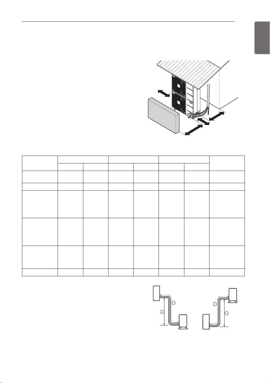
Piping length and the elevation
More than
300(11.8)
Fence or
obstacles
More than 700(27.6)
Awning
More than 600(23.6)
More than
More than
300(11.8)
300(11.8)
More than
300(11.8)
- If an awning is built over the unit to prevent direct
sunlight or rain exposure, make sure that heat
radiation from the condenser is not restricted.
- Ensure that the spaces indicated by arrows
around front, back and side of the unit.
- Do not place animals and plants in the path of
the warm air.
- Take the air conditioner weight into account and
select a place where noise and vibration are
minimum.
- Select a place so that the warm air and noise
from the air conditioner do not disturb neighbors.
INSTALLATION OF OUTDOOR UNIT
Installation Places
Unit : mm(inch)
Model
Pipe Size mm(inch) Length A Unit : m(ft) Elevation B Unit : m(ft)
Additional refrigerant
Unit : g/m(oz/ft)
Gas Liquid Standard Max. Standard Max.
KUSXB091A
KUSXB121A
Ø 9.52 (3/8) Ø 6.35 (1/4) 7.5 (24.6) 20 (66) 5 (16) 30 (98) 20 (0.22)
KUSXA121A
Ø
9.52 (3/8)
Ø
6.35 (1/4) 7.5 (24.6) 50 (164) 5 (16) 30 (98) 35 (0.38)
KUSXB181A
KUSXB241A
KUSXB301A
KUSXA181A
KUSXA241A
Ø15.88 (5/8)* Ø 9.52 (3/8) 7.5 (24.6) 50 (164) 5 (16) 30 (98) 35 (0.38)
KUSXB361A
KUSXB421A
KUSXB481A
KUSXA301A
KUSXA361A
Ø15.88 (5/8)* Ø 9.52 (3/8) 7.5 (24.6) 75 (246) 5 (16) 30 (98) 40 (0.43)
KUSXA421A
KUSXA422A
KUSXA481A
KUSXA482A
Ø15.88 (5/8)* Ø 9.52 (3/8) 7.5 (24.6) 75 (246) 5 (16) 30 (98) 40 (0.43)
KUSXB601A
Ø19.05 (3/4)**
Ø
9.52 (3/8) 7.5 (24.6) 75 (246) 5 (16) 30 (98) 40 (0.43)
If installed tube is shorter than 7.5 m(24.6 ft), additional
refrigerant charging is not necessary.
Additional Refrigerant = [A -7.5 m(2.46 ft)] x Additional
refrigerant [g(oz)]
In case of A-Coil combination (18~60kBtu/h),
* Installation Gas Pipe Size = Ø19.05mm (3/4inch)
** Installation Gas Pipe Size = Ø19.05mm (3/4inch) ~
Ø22.22mm (7/8inch)
In case of A-Coil combination (30~60kBtu/h, Exception KUSXB301A), charge additional refrigerant.
Additional refrigerant = 400g (14.1oz)
Ex) If installed tube is shorter than 7.5 m(24.6 ft), Charge additional refrigerant for A-Coil Combination [g(oz)]
Ex) If installed tube is more than 7.5 m(24.6 ft),
Total Additional Refrigerant
= { [A -7.5 m(2.46 ft)] x Additional refrigerant [g(oz)] } + additional refrigerant for A-Coil Combination [g(oz)]
Outdoor unit
Indoor unit
A
B
Outdoor unit
Indoor unit
A
B
ENGLISH
14
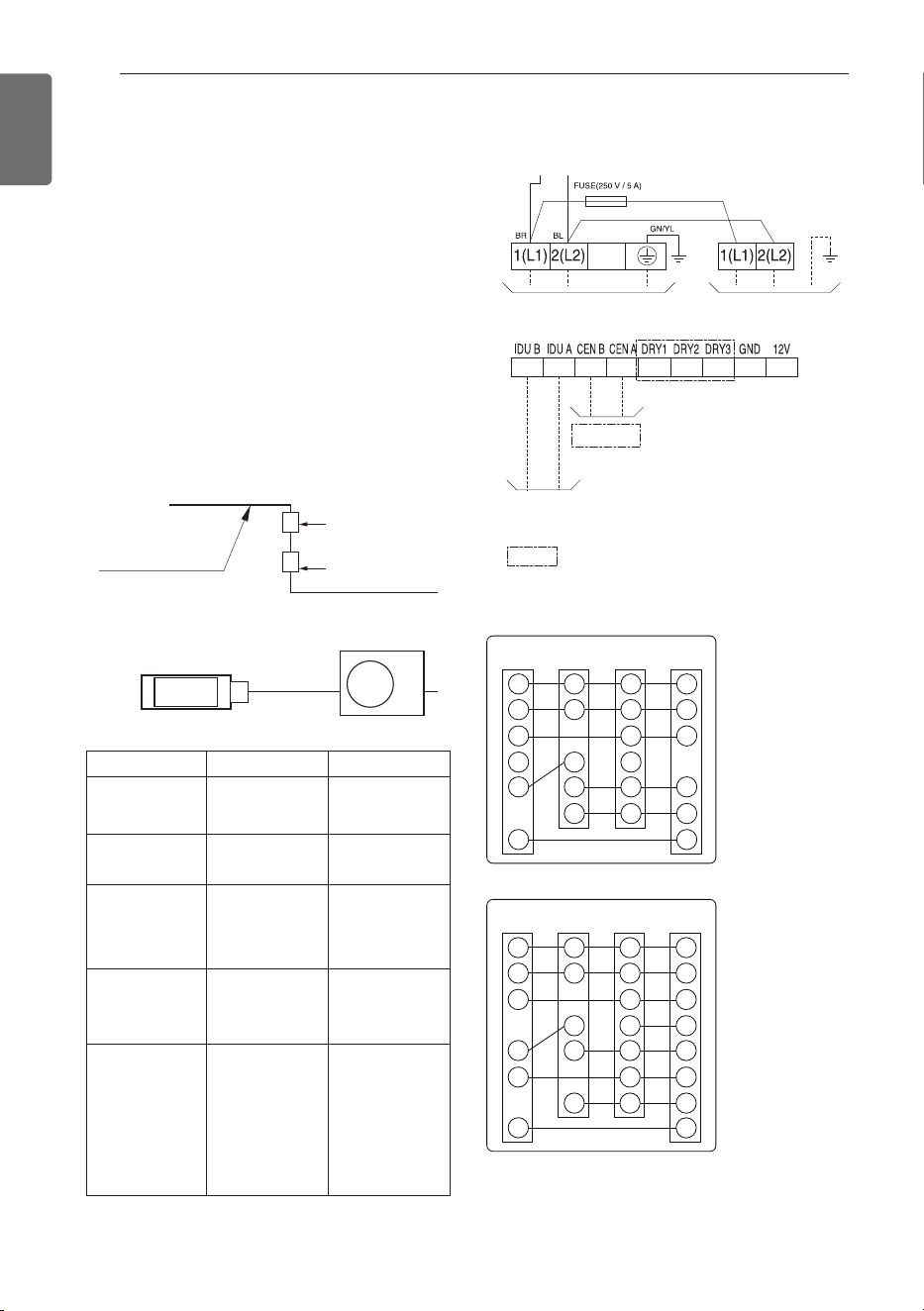
WIRING CONNECTION
Connecting Cables between
Indoor Unit and Outdoor Unit
Outdoor
Indoor
Main
power source
Switch box
ELCB
Central
Indoor Unit
Communication
Power Supply
1Ø, 208/230 V, 60 Hz
Indoor Unit
Power Supply
: The feature may be changed
according to the type of model.
Outdoor
unit
REF
Sensor
Furnace
Thermostat
R
C
Y1
Y-CC
W
Y2/Y
O/B
*
R
C
Y-Tstat
G
R
C
Y1
W
Y2/Y
G
R
C
W
Y
G
O/B
O/B
*
Outdoor
unit
REF
Sensor
Furnace
Thermostat
R
C
W2
W1
Y1
Y2/Y
O/B
G
R
C
W
Y1
Y2/Y
R
C
Y-Tstat
G
R
C
W2
Y-CC
W1
Y1
Y2/Y
G
< installing Coil & Furnace (Thermostat)>
- 1 Stage
- 2 Stage
Electrical Wiring
- All wiring must comply with local
requirements.
- Select a power source that is capable of
supplying the current required by the air
conditioner.
- Use a recognized ELCB(Electric Leakage
Circuit Breaker) between the power source
and the unit. A disconnection device to
adequately disconnect all supply lines must
be fitted.
- Model of circuit breaker recommended by
authorized personnel only.
WIRING CONNECTION
Model Power Source ELCB (A)
KUSXB091A
KUSXB121A
1Ø, 208/230 V 15
KUSXB181A
KUSXB241A
1Ø, 208/230 V 25
KUSXA121A
KUSXA181A
KUSXA241A
KUSXB301A
1Ø, 208/230 V 30
KUSXA301A
KUSXB361A
KUSXA361A
1Ø, 208/230 V 35
KUSXB421A
KUSXA421A
KUSXA422A
KUSXB481A
KUSXA481A
KUSXA482A
KUSXB601A
1Ø, 208/230 V 40
* Outdoor unit default “O” type.
(Heat Pump setting)
- It can change to “B” type by setting up the
DIP switch.
ENGLISH
WIRING CONNECTION
15
RECOMMENDATION
The power cord connected to the outdoor unit should comply with the following
specifications: NRTL Recognized(for example, UL or ETL recognized and CSA certified).
As always, final wire selection is governed by local codes and should be installed by a
licensed professional contractor.
Line voltage
(208/230 V)
GN/YL
20 mm
(25/32 inch)
Outdoor Unit Capacity (kBtu/h class) The minimum recommened wire size
9, 12(KUSXB121A)
AWG 14-3
12(KUSXA121A), 18, 24, 30(KUSXB301A)
AWG 12-3
30(KUSXA301A), 36, 42, 48, 60
AWG 10-3
[Power supply cable]
[Connecting cable]
Line voltage
(208/230 V)
GN/YL
20 mm
(25/32 inch)
elbac noitacinummoCelbac ylppus rewoP
Ⓐ Liquid pipe
Ⓑ Gas pipe
ⓒ Power lines
ⓓ
Insulating material
ⓔ
Communication lines
Communication
lines
Separation
Power
lines
E
D
D
B
A
C
Please refer to the instructions below for proper installation.
• Power wiring/power wiring gauge to the outdoor unit(s) must be solid or stranded and must
comply with all National Electrical Code (NEC), UL, and local electrical codes.
• Power wiring cable from the outdoor unit to the indoor unit must be a minimum of 14 AWG,
3-conductor, solid core or stranded, rated for 600 V.
• Communication wiring cable from the outdoor unit to the indoor unit must be minimum 18 AWG,
2-conductor, twisted, stranded, and shielded (shield must be grounded to the outdoor unit
chassis only).
ENGLISH
16
WIRING CONNECTION
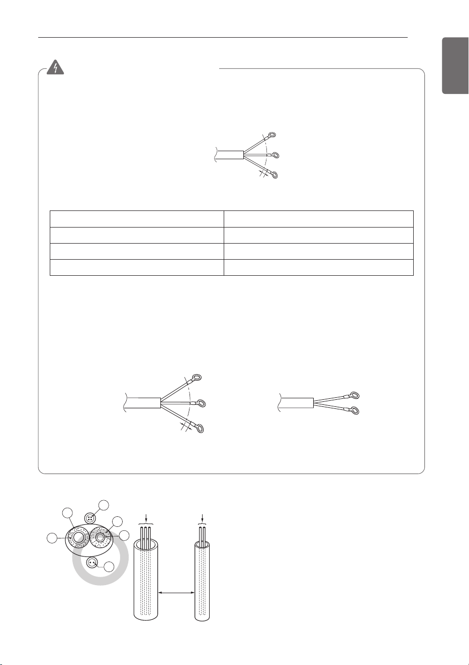
Precautions when laying power and ground wiring
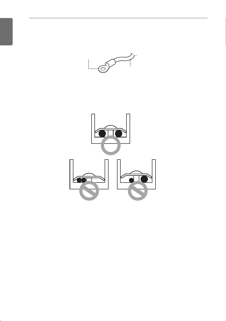
Use round pressure terminals for connections to the power terminal block.
When laying ground wiring, you must use round pressure terminals.
When none are available, follow the instructions below.
- Do not connect wiring of different thicknesses to the power terminal block. (Slack in the power wiring
may cause abnormal heat.)
- When connecting wiring which is the same thickness, do as shown in the figure below.
Power wire
(Ground wire)
Round pressure terminal
- For wiring, use the designated power wire and connect firmly, then secure to prevent outside
pressure being exerted on the terminal block.
- Use an appropriate screwdriver for tightening the terminal screws. A screwdriver with a small
head will strip the head and make proper tightening impossible.
- Over-tightening the terminal screws may break them.
ENGLISH
WIRING CONNECTION
17
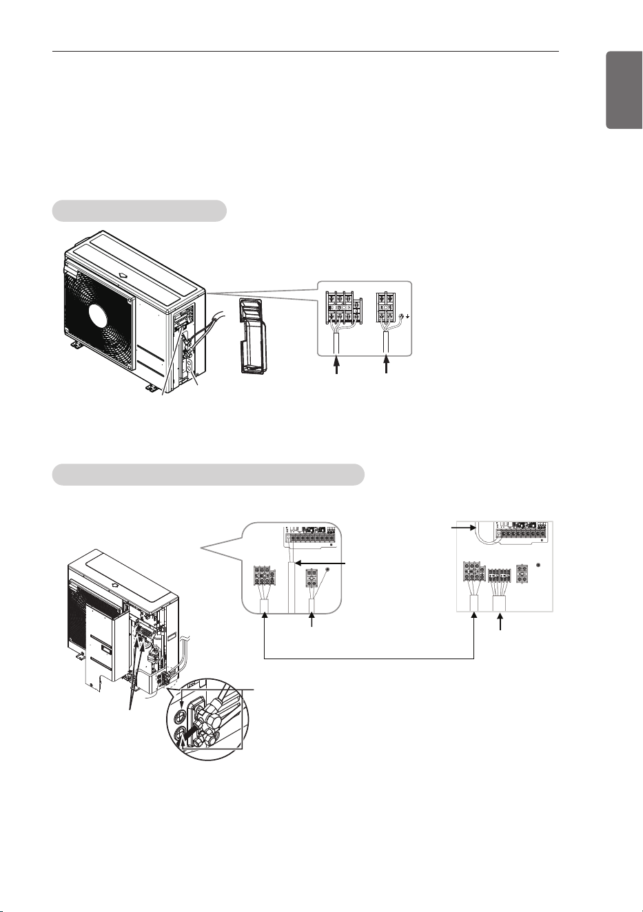
Connecting the cable to Outdoor Unit
- Remove the side panel for wiring connection.
- Use the cord clamp to fix the cord.
- Earthing work
Connect the cable of diameter more to the earthing terminal provided in the control box and do
earthing.
Cord clamp
conduit
Communication
cable terminal
Power cable
terminal
Cord clamp
* Make sure the rubber bushes are Properly used in
knock-out holes after connecting main Power cable
<Installing LG IDUs>
<Installing A-Coil & Furnace>
Connecting
cable terminal
Power cable
terminal
G/F Comm.
line
Furnace
(Thermostat)
cable terminal
Communication
cable terminal
9, 12 (KUSXB121A) kBtu/h
12 (KUSXA121A), 18, 24, 30 (KUSXB301A) kBtu/h
ENGLISH
18
WIRING CONNECTION
CAUTION
!
• The Power cord connected to the unit should be selected according to the following
specifications.
CAUTION
!
• The circuit diagram is not subject to change without notice.
• Be sure to connect wires according to the wiring diagram.
• Connect the wires firmly, so that not to be pulled out easily.
• Connect the wires according to color codes by referring the wiring diagram.
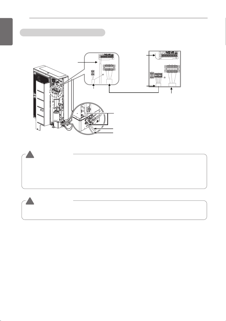
* Make sure the rubber bushes are
properly used in knock-out holes
after connecting main power.
Power cable terminal
Connecting cable terminal
<Installing LG IDUs>
<Installing A-Coil & Furnace>
Connecting
cable terminal
Power cable terminal
G/F Comm.
line
Furnace
(Thermostat)
cable terminal
Communication
cable terminal
30(KUSXA301A), 36, 42, 48, 60 kBtu/h
ENGLISH
CONNECTING COPPER PIPES
19
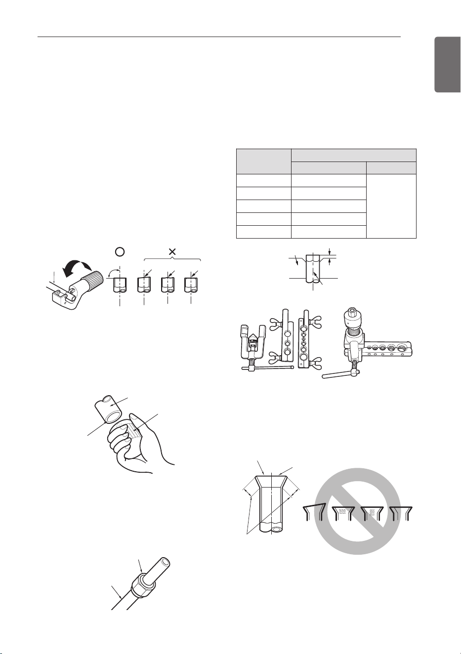
Preparation of Piping
Main cause of gas leakage is defect in flaring
work. Carry out correct flaring work in the
following procedure.
Cut the pipes and the cable.
- Use the accessory piping kit or the pipes
purchased locally.
- Measure the distance between the indoor
and the outdoor unit.
- Cut the pipes a little longer than measured
distance.
- Cut the cable 1.5 m(4.9 ft) longer than the
pipe length.
Burrs removal
- Completely remove all burrs from the cut
cross section of pipe.
- Put the end of the copper tubing to
downward direction as you remove chips in
order to avoid to let chips drop in the pipe.
Putting nut on
- Remove flare nuts attached to indoor and
outdoor units, than put them on pipe/tube
having completed burr removal.
(Not possible to put them on after flaring
work)
Flaring work
- Firmly hold copper tube in a bar(or die) as
indicated dimension in the table above.
- Carry out flaring work using dedicated flaring
tool for R-410A as shown below.
Check
- Compare the flared work with figure below.
- If flare is noted to be defective, cut off the
flared section and do flaring work again.
Copper
tubing
90 °
Slanted Uneven Rough
Pipe
Reamer
Point down
Flare nut
Copper tubing
Pipe diameter
Inch (mm)
A inch (mm)
Wing nut type Clutch type
Ø 1/4 (Ø 6.35) 0.04~0.05 (1.1~1.3)
0~0.02
(0~0.5)
Ø 3/8 (Ø 9.52) 0.06~0.07 (1.5~1.7)
Ø 1/2 (Ø 12.7) 0.06~0.07 (1.6~1.8)
Ø 5/8 (Ø 15.88)
0.06~0.07 (1.6~1.8)
Ø 3/4 (Ø 19.05)
0.07~0.08 (1.9~2.1)
<Wing nut type>
<Clutch type>
Bar
Copper pipe
"A"
Inclined
Inside is shining without scratches
Smooth all round
Even length
all round
Surface
damaged
Cracked Uneven
thickness
= Improper flaring =
CONNECTING COPPER PIPES
ENGLISH
20
CONNECTING COPPER PIPES
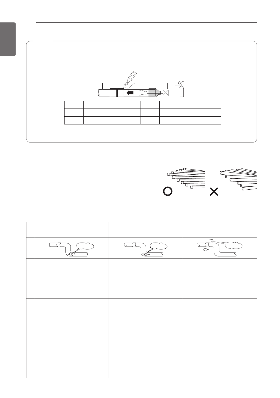
NOTE
Always blow nitrogen into pipe which is brazed. Always use a non-oxidizing brazing material
for brazing the parts and do not use flux. If not, oxidized film can cause clogging or damage
to the compressor unit and flux can harm the copper piping or refrigerant oil.
• The torch tip should be positioned at the opposite angle to shop the correct way to apply
heat on the pipe coupling.
1 Refrigerant piping 4 Taping
2 Pipe to be brazed 5 Valve
3 Nitrogen 6 Pressure-reducing valve
Plumbing materials and storage methods
Pipe must be able to obtain the specified thickness and
should be used with low impurities. Also when handling
storage, pipe must be careful to prevent a fracture,
deformity and wound.
Should not be mixed with contaminations such as dust,
moisture.
Refrigerant piping on three principles
Drying Cleanliness Airtight
Should be no moisture inside No dust inside. There is no refrigerant leakage
Items
Moisture
Dust
Leakage
Cause failure
- Significant hydrolysis of refrigerant
oil
- Degradation of refrigerant oil
- Poor insulation of the compressor
- Do not cold and warm
- Clogging of EEV, Capillary
- Degradation of refrigerant oil
- Poor insulation of the compressor
- Do not cold and warm
- Clogging of EEV, Capillary
- Gas shortages
- Degradation of refrigerant oil
- Poor insulation of the compressor
- Do not cold and warm
Countermeasure
- No moisture in the pipe
- Until the connection is completed,
the plumbing pipe entrance should
be strictly controlled.
- Stop plumbing at rainy day.
- Pipe entrance should be taken
side or bottom.
- When removal burr after cutting
pipe, pipe entrance should be
taken down.
- Pipe entrance should be fitted cap
when pass through the walls.
- No dust in the pipe.
- Until the connection is completed,
the plumbing pipe entrance should
be strictly controlled.
- Pipe entrance should be taken
side or bottom.
- When removal burr after cutting
pipe, pipe entrance should be
taken down.
- Pipe entrance should be fitted cap
when pass through the walls.
- Airtightness test should be.
- Brazing operations to comply with
standards.
- Flare to comply with standards.
- Flange connections to comply with
standards.
3
2
1
45
6
ENGLISH
CONNECTING COPPER PIPES
21
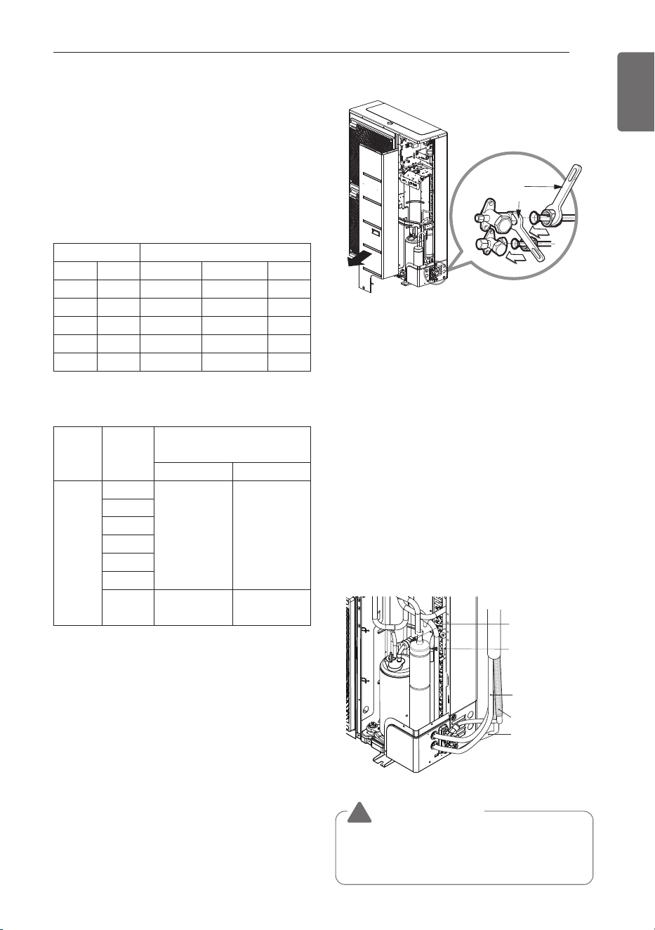
Connecting the pipes to the
Outdoor unit
- Align the center of the piping and sufficiently
tighten the flare nut by hand.
- Finally, tighten the flare nut with torque
wrench until the wrench clicks.
When tightening the flare nut with torque
wrench, ensure the direction for tightening
follows the arrow on the wrench.
h When connecting the A-Coil to the Outdoor
unit, connect the installed pipe by brazing.
Use the accessory Connector for A-Coil
connection pipe (Brazing)
- When installing the A-Coil, use the connector
provided as an accessory.
- Connect the nut of the connector to the
outdoor unit, then braze the appropriate pipe
diameter on the other side.
Preventing foreign objects from entering
(Figure1)
- Plug the pipe through-holes with putty or
insulation material(procured locally)to stop
up all gaps, as shown in the figure 1.
CAUTION
!
• Insects or small animals entering the
outdoor unit may cause a short circuit in
the electrical box.
* When tighten the pipe, hold the hexagonal
body.
<Figure 1>
Drain hose
Communication
cable
Liquid side piping
Gas side piping
Refrigerant pipe
ContinuousContinuousContinuous
Torque
wrench
Piping Size Torque
mm inch kgf·cm N·m lbf·ft
Ø 6.35 Ø 1/4 180 ~ 250 17.6 ~ 24.5 13 ~ 18
Ø 9.52 Ø 3/8 340 ~ 420 33.3 ~ 41.2 25 ~ 30
Ø 15.88 Ø 5/8 630 ~ 820 61.7 ~ 80.4 45 ~ 59
Ø 12.7 Ø 1/2 550 ~ 660 53.9 ~ 64.7 40 ~ 48
Ø 19.05 Ø 3/4 990 ~ 1 210 97.0 ~ 118.7 71 ~ 87
IDU
Capacity
(kBtu/h)
Installed pipe size
(inch (mm))
Liquid Gas
A-Coil
18
3/8 (Ø 9.52) 3/4 (Ø19.05)
24
30
36
42
48
60 3/8 (Ø 9.52)
3/4 (Ø19.05)
~7/8 (Ø22.22)
ENGLISH
22
CHARGING
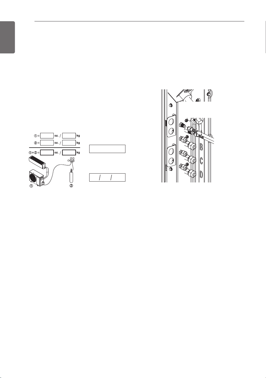
Checking the safe handling
Note down all of the following information on the
label, especially the resulting total
REFRIGERANT CHARGE for each
REFRIGERATING SYSTEM
- ① Refrigerant charge of the precharged part of
the appliance
- ② Refrigerant charge added during installation
- Total REFRIGERANT CHARGE
- Refrigerant type
- Date of first charge
Refrigerant type
Type de réfrigérant
Date of first charge
Date de la première charge
mm / dd/ yyyy
Mark refrigerant pipes with red Pantone®
Matching System (PMS) #185 or RAL 3020
after flare fittings or brazing. This marking
must extend a minimum of 1 inch (25mm) in
both directions and shall be replaced if
removed.
Return all labels, especially red marking, to
their original condition to ensure the next
consumer or servicer is aware of the presence
of a flammable refrigerant.
Ensure that the red marking for flammable
refrigerant identification in the process tube
area is visible following servicing.
h The feature may be changed according to
the type of model.
Red marking on the
Refrigerant Pipe.
(Field Supplied)
CHARGING
ENGLISH
CHARGING
23
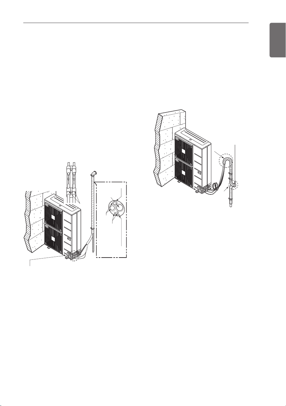
Forming the piping
Form the piping by wrapping the
connecting portion of the indoor unit with
insulation material and secure it with two
kinds of vinyl tape.
- If you want to connect an additional drain
hose, the end of the drain outlet should be
routed above the ground. Secure the drain
hose appropriately.
In cases where the outdoor unit is installed
below the indoor unit perform the
following.
1 Tape the piping, drain hose and connecting
cable from down to up.
2 Secure the tapped piping along the exterior
wall using saddle or equivalent.
In cases where the outdoor unit is installed
above the indoor unit perform the
following.
1 Tape the piping and connecting cable from
down to up.
2 Secure the taped piping along the exterior
wall. Form a trap to prevent water entering
the room.
3 Fix the piping onto the wall by saddle or
equivalent.
• Trap is required to prevent water from entering
into electrical parts.
Taping
Drain hose
Pipings
Connecting
cable
Power supply
cord
Plastic
Plastic
band
band
Plastic
band
Seal a small
opening around the
pipings with gum
type sealant.
Trap
Trap
Trap
Trap
Seal a small opening
Seal a small opening
around the pipings
around the pipings
with gum type sealer.
with gum type sealer.
Seal a small opening
around the pipings
with gum type sealant.
ENGLISH
24
LEAKAGE TEST AND EVACUATION
Air and moisture remaining in the refrigerant
system have undesirable effects as indicated
below.
1 Pressure in the system rises.
2 Operating current rises.
3 Cooling(or heating) efficiency drops.
4 Moisture in the refrigerant circuit may
freeze and block capillary tubing.
5 Water may lead to corrosion of parts in the
refrigeration system.
Therefore, the indoor/outdoor unit and
connecting tube must be checked for leak
tight, and vacuumed to remove incondensable
gas and moisture in the system.
Preparation
Check that each tube(both liquid and gas side
tubes) between the indoor and outdoor units
have been properly connected and all wiring
for the test run has been completed. Remove
the service valve caps from both the gas and
the liquid side on the outdoor unit. Check that
both the liquid and the gas side service valves
on the outdoor unit are kept closed at this
stage.
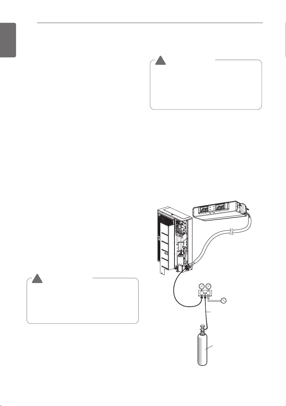
Leakage test
Connect the manifold valve(with pressure
gauges) and dry nitrogen gas cylinder to this
service port with charge hoses.
Pressurize the system to no more than 3.0
MPa (427 P.S.I.G) with dry nitrogen gas and
close the cylinder valve when the gauge
reading reached 3.0 MPa (427 P.S.I.G) Next,
test for leaks with liquid soap.
1 Do a leakage test of all joints of the
tubing(both Indoor unit and outdoor unit)
and both gas and liquid side service
valves.
Bubbles indicate a leak. Be sure to wipe off
the soap with a clean cloth.
2 After the system is found to be free of
leaks, relieve the nitrogen pressure by
loosening the charge hose connector at the
nitrogen cylinder. When the system
pressure is reduced to normal, disconnect
the hose from the cylinder.
Charge hose
Indoor unit
Outdoor unit
Manifold valve
Lo Hi
Pressure
gauge
Nitrogen gas
cylinder(in vertical
standing position)
LEAKAGE TEST AND EVACUATION
CAUTION
!
• To avoid nitrogen entering the refrigerant
system in a liquid state, the top of the
cylinder must be higher than its bottom
when you pressurize the system. Usually,
the cylinder is used in a vertical standing
position.
CAUTION
!
• Be sure to use a manifold valve for
leakage test.
If it is not available, use a stop valve for
this purpose. The "Hi" knob of the
manifold valve must always be kept close.
ENGLISH
LEAKAGE TEST AND EVACUATION
25
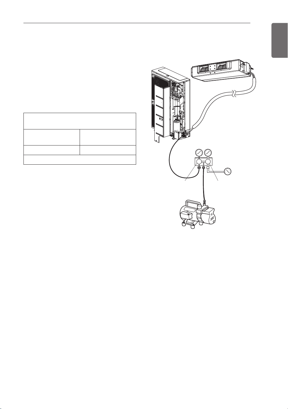
Evacuation
1 Connect the charge hose end described in
the preceding steps to the vacuum pump to
evacuate the tubing and indoor unit.
Confirm the "Lo and Hi" knob of the
manifold valve is open. Then, run the
vacuum pump.
The operation time for evacuation varies
with tubing length and capacity of the
pump. The following table shows the time
required for evacuation.
2 When the desired vacuum is reached,
close the "Lo and Hi" knob of the manifold
valve and stop the vacuum pump.
Finishing the job
1 With a service valve wrench, turn the valve
stem of liquid side valve counter-clockwise
to fully open the valve.
2 Turn the valve stem of gas side valve
counter-clockwise to fully open the valve.
3 Loosen the charge hose connected to the
gas side service port slightly to release the
pressure, then remove the hose.
4 Replace the flare nut and its bonnet on the
gas side service port and fasten the flare
nut securely with an adjustable wrench.
This process is very important to prevent
leakage from the system.
5 Replace the valve caps at both gas and
liquid side service valves and fasten them
tight.
This completes air purging with a vacuum
pump.
The air conditioner is now ready to test run.
Required time for evacuation when 30
gal/h(114 l/h) vacuum pump is used
If tubing length is less
than 10 m(33 ft)
If tubing length is
longer than 10 m(33 ft)
30 minutes or more 60 minutes or more
0.07 kPa (0.01 psi)(0.53 torr) or less
Outdoor unit
Manifold valve
Vacuum pump
Open Open
Pressure
gauge
Lo Hi
Indoor unit
ENGLISH
26
TEST RUNNING
TEST RUNNING
Precautions in test running
- The initial power supply must provide at least
90 % of the rated voltage.
Otherwise, the air conditioner should not be
operated.
Check the following items when
installation is complete
- After completing work, be sure to measure
and record trial run properties, and store
measured data, etc.
- Measuring items are room temperature,
outside temperature, suction temperature,
blow out temperature, wind velocity, wind
volume, voltage, current, presence of
abnormal vibration and noise, operating
pressure, piping temperature, compressive
pressure.
- As to the structure and appearance, check
following items.
* Is the circulation of air adequate?
* Is the draining smooth?
* Is the heat insulation complete
(refrigerant and drain piping)?
* Is there any leakage of refrigerant?
* Is the remote controller switch operated?
* Is there any faulty wiring?
* Are not terminal screws loosened?
M4......118 N·cm (10.4 lbs·inch)
M5......196 N·cm (17.3 lbs·inch)
M6......245 N·cm (21.7 lbs·inch)
M8......588 N·cm (52 lbs·inch)
Connection of power supply
- Connect the power supply cord to the
independent power supply.
Circuit breaker is required.
- Operate the unit for fifteen minutes or more.
Evaluation of the performance
- Measure the temperature of the intake and
discharge air.
- Ensure the difference between the intake
temperature and the discharge one is more
than 8 °C (Cooling) or reversely (Heating).
HAND OVER
Teach the customer the operation and
maintenance procedures, using the operation
manual.
(air filter cleaning, temperature control, etc.)
Thermometer
NOTE
• For test run, carry out the cooling
operation firstly even during heating
season. If heating operation is carried
out firstly, it leads to the trouble of
compressor. Then attention must be
paid.
• Carry out the test run more than 5
minutes without fail.
(Test run will be cancelled 18 minutes
later automatically)
- The test run is started by pressing the
room temperature checking button and
down timer button for 3 seconds at the
same time.
- To cancel the test run, press any
button.
ENGLISH
SELF-DIAGNOSIS FUNCTION
27
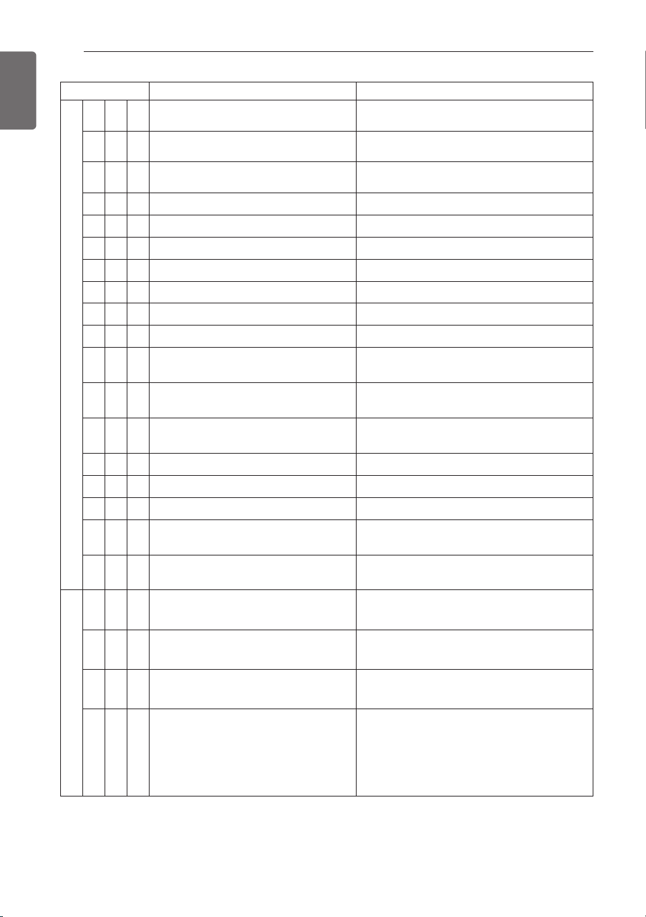
SELF-DIAGNOSIS FUNCTION
* Indoor unit related errors are not displayed in the 7-segment of main PCB.
Error Indicator
- This function indicates types of failure in self-diagnosis and occurrence of
failure for air condition.
- Error mark is displayed on display window of indoor units and wired
remote controller, and 7-segment LED of outdoor unit control board as
shown in the table.
- If more than two troubles occur simultaneously, lower number of error
code is first displayed.
- After error occurrence, if error is released, error LED is also released
simultaneously.
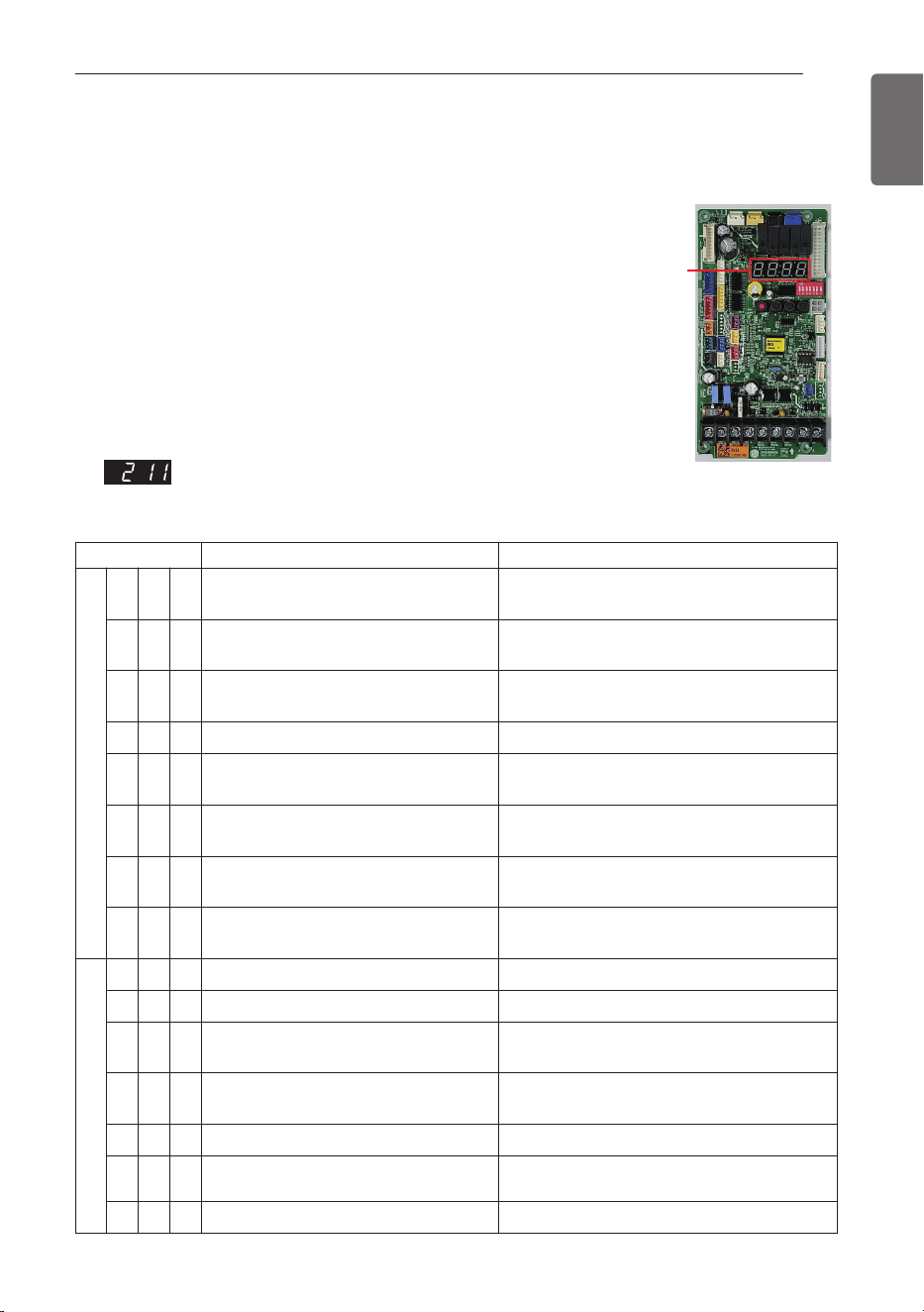
Error Display
2nd, 3rd, 4th LED of 7-segment of main pcb indicates error number.
Ex)
Display Title Cause of Error
Indoor unit related error
0 1 - Air temperature sensor of indoor unit
Air temperature sensor of indoor unit is open
or short
0 2 -
Inlet pipe temperature sensor of indoor
unit
Inlet pipe temperature sensor of indoor unit is
open or short
0 3 -
Communication error : wired remote
controller ↔ indoor unit
Failing to receive wired remote controller
signal in indoor unit PCB
0 4 - Drain pump Malfunction of drain pump
0 5 -
Communication error : outdoor unit ↔
indoor unit
Failing to receive outdoor unit signal in indoor
unit PCB
0 6 -
Outlet pipe temperature sensor of
indoor unit
Outlet pipe temperature sensor of indoor unit
is open or short
0 9 - Indoor EEPROM Error
In case when the serial number marked on
EEPROM of Indoor unit is 0 or FFFFFF
1 0 - Poor fan motor operation
Disconnecting the fan motor connector/Failure
of indoor fan motor lock
Outdoor unit related error
2 1 1 Inv. PCB IPM Fault occur Inv. PCB Drive IPM Fault
2 2 1 AC Input Current Over Error AC Input Current excess (RMS)
2 3 1
Inverter Compressor DC link Low
Voltage
DC charging is not performed at Outdoor Unit
after starting relay turn on
2 4 1
Excessive rise of discharge pressure in
outdoor compressor
Compressor off due to the high pressure
switch in outdoor unit
2 5 1 Input Voltage High/ Low Voltage Input voltage is over or less limited value
2 6 1 Inverter Compressor Start Failure
Starting failure because of compressor
abnormality
2 7 1 PSC / PFC Fault Error Over-current on AC ↔ DC converter circuit
7-Segment
Main PCB
ENGLISH
28
SELF-DIAGNOSIS FUNCTION
Display Title Cause of Error
Outdoor unit related error
2 9 1 Inverter Compressor Over Current
Inverter compressor input current is over limited
value
3 2 1
Over-increase discharge temp. of inverter
compressor
Compressor is off because of over-increase
discharge temp. of inverter compressor
3 5 1
Excessive drop of discharge pressure of
compressor
excessive drop of low pressure by the low
pressure sensor
4 0 1 Inverter Compressor CT Sensor Fault Inverter Compressor CT Sensor open or short
4 1 1 Discharge pipe temp. sensor error Discharge pipe temp. sensor open or short
4 3 1 Sensor error of high pressure Pressure sensor open or short
4 4 1 Air Temp. sensor error Air Temp. sensor open or short
4 5 1 Condenser mid-pipe Temp. sensor error Condenser mid-pipe Temp. sensor open or short
4 6 1 Suction pipe temp. sensor error Suction pipe temp. sensor open or short
4 8 1 Condenser out-pipe Temp. sensor error Condenser out-pipe Temp. sensor open or short
5 2 1
Communication error : inverter PCB ↔
Main PCB
Failing to receive inverter signal at main PCB of
Outdoor Unit
5 3 1
Communication error : indoor unit ↔ Main
PCB of Outdoor Unit
Failing to receive indoor unit signal at main PCB
of Outdoor Unit
5 7 1
Communication error : Main PCB ↔
inverter PCB
Failing to receive signal main PCB at inverter
PCB of Outdoor Unit
6 1 1 Condenser overheating error High temperature in outdoor condenser mid-pipe
6 2 1 Inverter Heatsink High Temperature Heatsink Temperature is over limited value
6 7 1 Fan lock error Outdoor Fan is not operation
7 3 1
AC input instant over current error (Matter
of software)
Inverter PCB input power current is over limited
value
8 6 1 Main PCB EEPROM Error
Communication Fail Between Outdoor Unit Main
MICOM and EEPROM or omitting EEPROM
Refrigerant leakage sensor related error
2 2 8
Refrigerant leak detector malfunction
error
Refrigerant leak detector has failed
2 2 9 Refrigerant leak detector lifetime error
The lifetime of the refrigerant leak detector has
reached the end
2 3 0 Refrigerant leak detection error
Refrigerant leak detected by refrigerant leak
detector
2 3 6 Refrigerant leak detector lifetime pre-alarm
An error occurs once a month when the lifespan
of the leak detector has elapsed 9 years and 6
months. An error occurs once a day when the
lifespan of the leak detector has elapsed 9 years
and 11 months.
ENGLISH
SELF-DIAGNOSIS FUNCTION
29
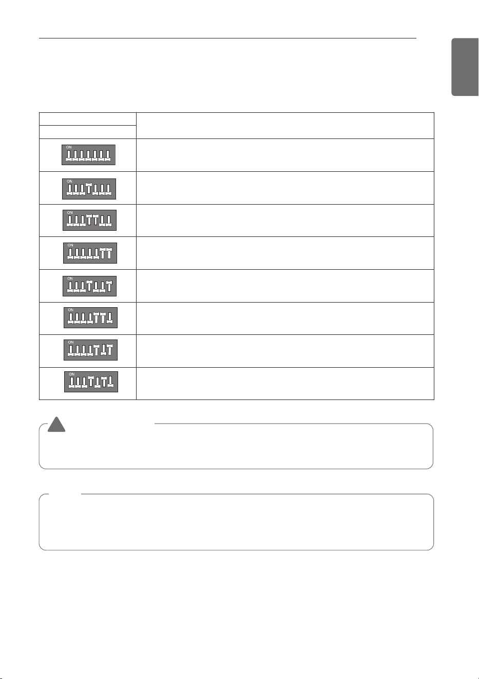
DIP S/W Setting
If you set the DIP Switch when power is on, the change in setting is not applicable.
The changing setting is enabled only when Power is reset.
NOTE
• Unless the applicable DIP switch is set properly, the product may not work.
• If you want to set a specific function, request that the installer sets the DIP switch
appropriately during installation.
WARNING
!
• When you set the DIP switch, you should turn off the circuit breaker or shut the power source of
the product down.
DIP Switch
Function
1 2 3 4 5 6 7
1 234 5 6 7
Normal Operation (No Function)
1 234 5 6 7
Pump Down
Mode Lock (Cooling)
Mode Lock (Heating)
Night Quiet Mode (Step 1)
Night Quiet Mode (Step 2)
Mode Lock (Cooling) + Night Quiet Mode (Step 1)
Mode Lock (Cooling) + Night Quiet Mode (Step 2)
1 234 5 6 7
1 234 5 6 7
1 234 5 6 7
1 234 5 6 7
1 234 5 6 7
1 234 5 6 7
ENGLISH
30
SELF-DIAGNOSIS FUNCTION
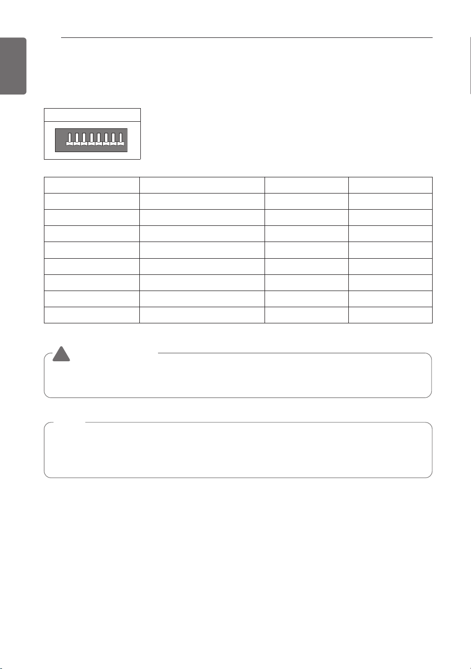
Unitary Comm. Kit DIP S/W Setting
If you set the DIP Switch when power is on, the change in setting is not applicable.
The changing setting is enabled only when Power is reset.
DIP Switch
1
ON
OFF
234567 8
DIP Switch (SW01) Function ON OFF
1 ODU Communication X O
2 Remote Controller O X
3 Thermostat H/P Setting B Type O Type
4 Stage Setting 1 Stage 2 Stage
5 Reserved - -
6 Reserved - -
7 Reserved - -
8 Reserved - -
NOTE
• Unless the applicable DIP switch is set properly, the product may not work.
• If you want to set a specific function, request that the installer sets the DIP switch
appropriately during installation.
WARNING
!
• When you set the DIP switch, you should turn off the circuit breaker or shut the power source of
the product down.
ENGLISH
INSTALLATION GUIDE AT THE SEASIDE
31
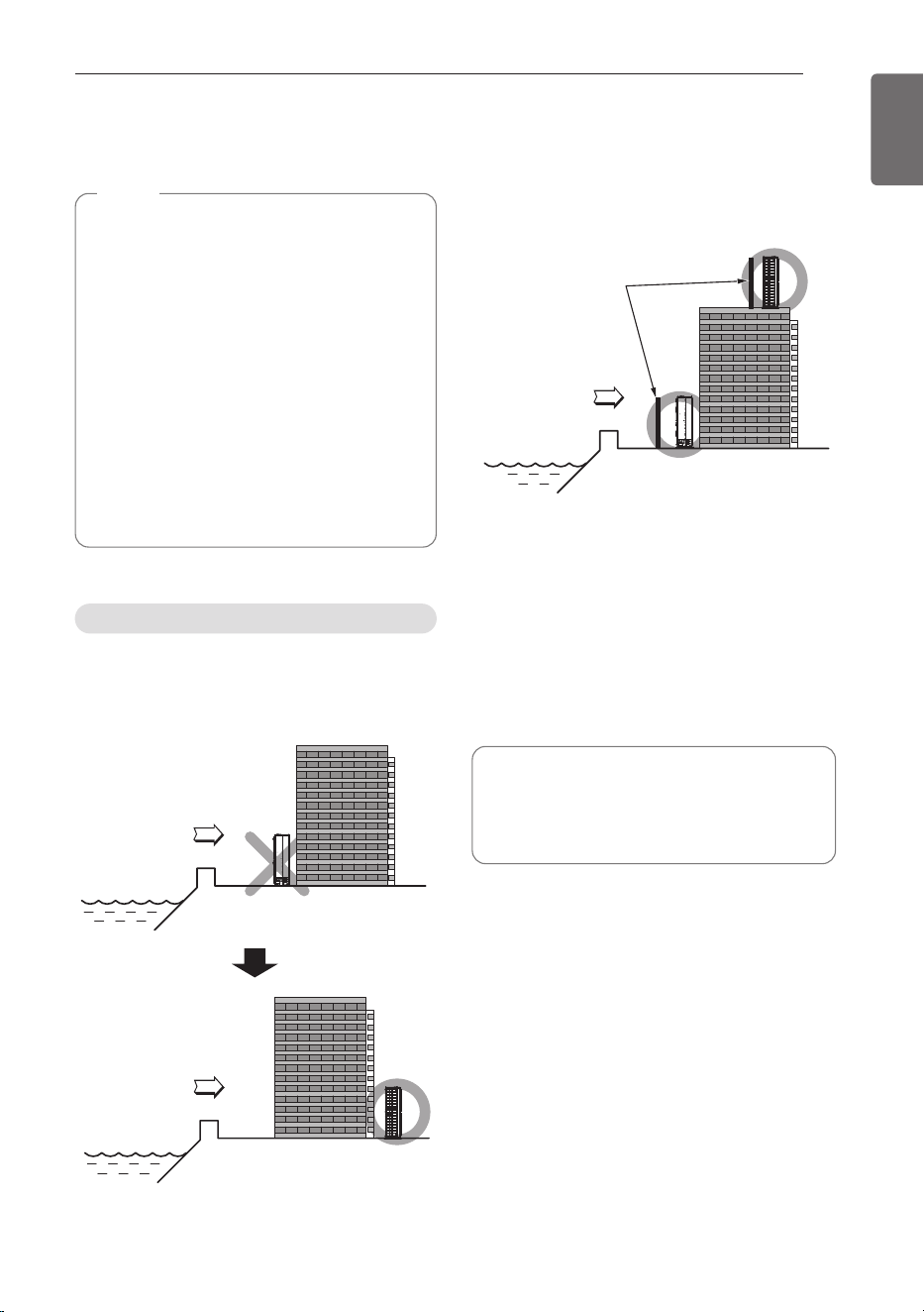
If the outdoor unit is to be installed close to the
seaside, direct exposure to the sea wind
should be avoided. Install the outdoor unit on
the opposite side of the sea wind direction.
In case, to install the outdoor unit on the
seaside, set up a windbreak not to be exposed
to the sea wind.
- It should be strong enough like concrete to
prevent the sea wind from the sea.
- The height and width should be more than
150 % of the outdoor unit.
- It should be keep more than 70 cm of space
between outdoor unit and the windbreak for
easy air flow.
Select a well-drained place.
Selecting the location(Outdoor unit)
Sea wind
Sea wind
Sea wind
Windbreak
• Periodic ( more than once/year )
cleaning of the dust or salt particles
stuck on the heat exchanger by using
water
INSTALLATION GUIDE AT THE SEASIDE
NOTE
• Air conditioners should not be installed in
areas where corrosive gases, such as
acid or alkaline gas, are produced.
• Do not install the product where it could
be exposed to sea wind (salty wind)
directly. It can result corrosion on the
product. Corrosion, particularly on the
condenser and evaporator fins, could
cause product malfunction or inefficient
performance.
• If outdoor unit is installed close to the
seaside, it should avoid direct exposure
to the sea wind. Otherwise it needs
additional anticorrosion treatment on the
heat exchanger.
ENGLISH
32
SEASONAL WIND AND CAUTIONS IN WINTER
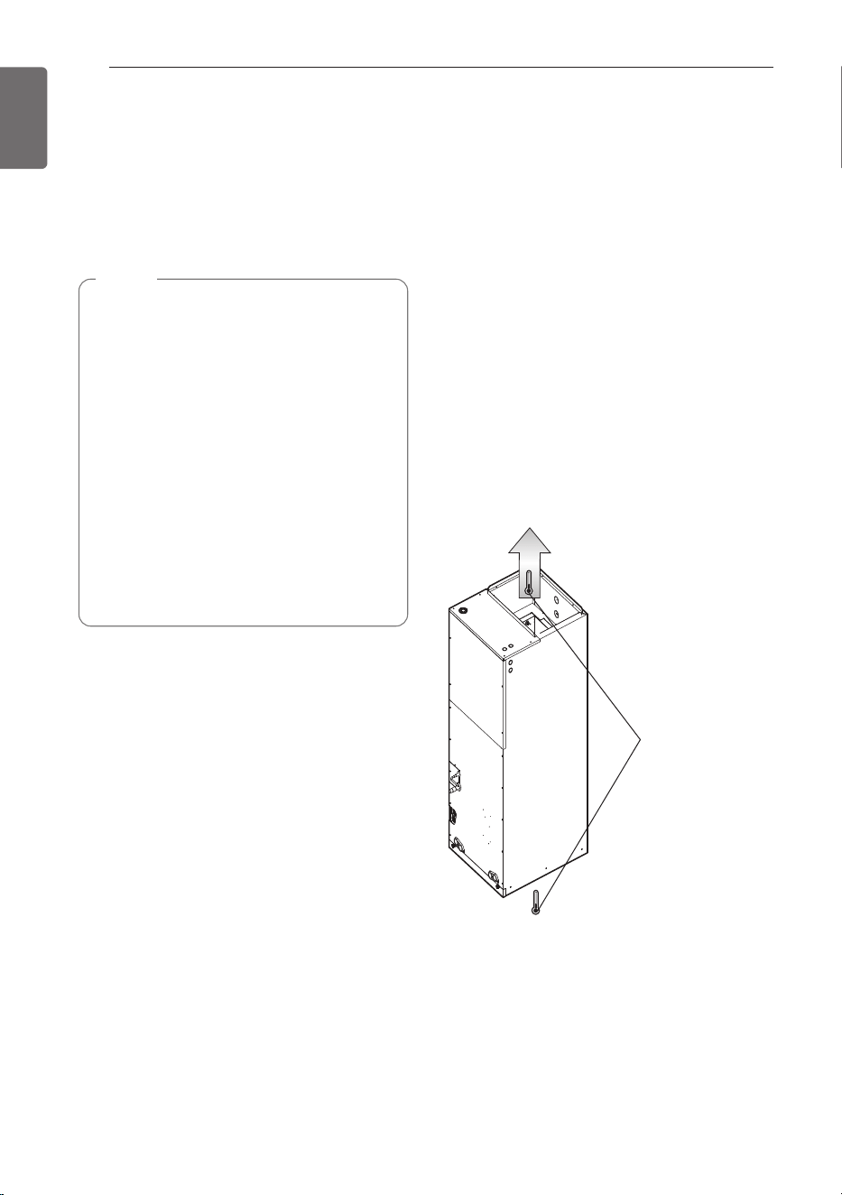
SEASONAL WIND AND CAUTIONS IN WINTER
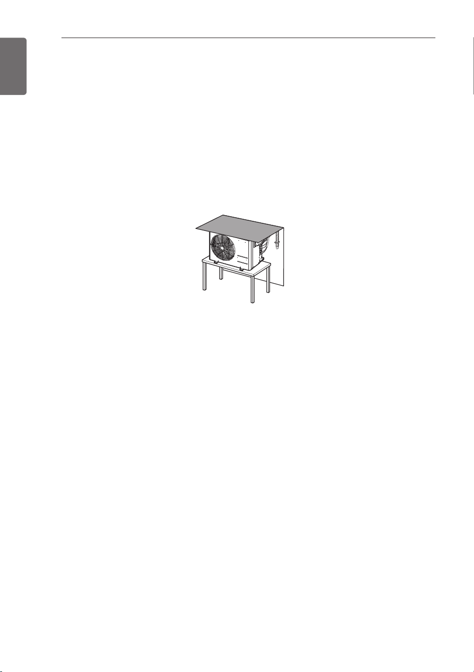
- Sufficient measures are required in a snow area or severe cold area in winter so that product
can be operated well.
- Get ready for seasonal wind or snow in winter even in other areas.
- Install a suction and discharge duct not to let in snow or rain.
- Install the outdoor unit not to come in contact with snow directly. If snow piles up and freezes on
the air suction hole, the system may malfunction. If it is installed at snowy area, attach the hood
to the system.
- Install the outdoor unit at the higher installation console by 50 cm than the average snowfall
(annual average snowfall) if it is installed at the area with much snowfall.
- Where snow accumulated on the upper part of the Outdoor Unit by more than 10 cm, always
remove snow for operation.
1. The height of H frame must be more than 2 times the snowfall and its width shall not exceed
the width of the product. (If width of the frame is wider than that of the product, snow may
accumulate)
2. Don't install the suction hole and discharge hole of the Outdoor Unit facing the seasonal wind.