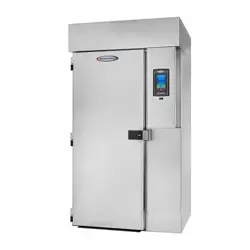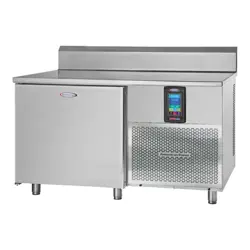
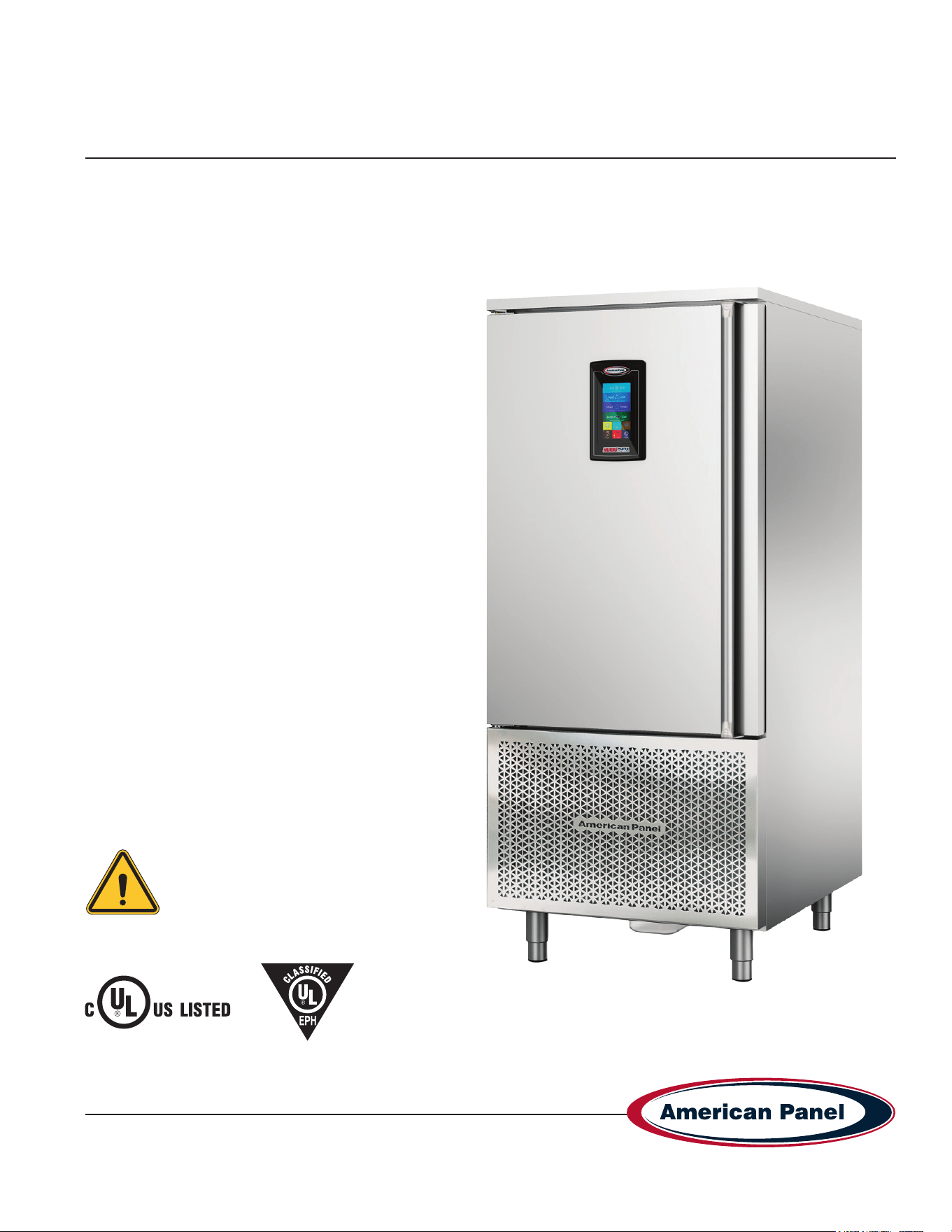
Installation & Operators Manual
HURRiCHiLL™ touchscreen R290 blast chillers & shock freezers
Please read this manual
before installing or
operation of this equipment.
This manual is updated as new information and models are released. Visit our website for the latest manual.
990260_APC_HC-TS_OEM
08/25
5800 SE 78th St. Ocala, FL 34472 • 352.245.7055 • [email protected]
Versatile, Dependable Walk-Ins & Blast Chillers
MODELS COVERED:
AP7BCF70-2-P
AP7BCF70-2-C-P
AP10BCF100-2-P
AP12BCF150-2-P
AP20BCF200-3-P
Part #: 990260
5800 SE 78th St. Ocala, FL 34472
2
P: (800) 327-3015
Touchscreen HURRiCHiLL Installation & Operations Manual
Warranty .................................................................................................................................................................3-4
Basic Safety Information............................................................................................................................................5
Equipment Tag ...........................................................................................................................................................6
Pre-installation Checks ..............................................................................................................................................6
Installation ............................................................................................................................................................7-10
Installation Checklist ..................................................................................................................................................7
Proper Clearances & Location Check .......................................................................................................................8
Specications & Performance ................................................................................................................................. 11
Cycles & Modes Explained ................................................................................................................................. 12-14
Factory Presets .......................................................................................................................................................15
Unit Operation ....................................................................................................................................................16-23
- Home Screen ............................................................................................................................................16
- Automatic Mode Screen ............................................................................................................................ 17
- Start a Cycle in Automatic Mode ............................................................................................................... 18
- Manual Mode Screen ................................................................................................................................ 19
- Start a Cycle in Manual Mode ................................................................................................................... 20
- A La Carte Mode Screen ........................................................................................................................... 21
- Start a Cycle in A La Carte Mode .............................................................................................................. 22
- Start a Cycle in Quick Start Mode ............................................................................................................. 23
- Customize the Quick Start Button ............................................................................................................. 23
PC Connection Package .........................................................................................................................................24
Connect to Controller - Direct Connection ...............................................................................................................24
Connect to Controller - WiFi ...............................................................................................................................25-26
Connect to Controller - WiFi Notication Setup ....................................................................................................... 27
HACCP Download via USB .....................................................................................................................................27
HACCP Download via Peer to Peer ........................................................................................................................28
HACCP Download via WiFi .....................................................................................................................................28
Customizing the Cycles ......................................................................................................................................29-30
Temperature Probe Adjustments .............................................................................................................................30
General Operating Instructions................................................................................................................................31
Maintenance Instructions....................................................................................................................................31-33
Evaporator Coil Cleaning.........................................................................................................................................34
Replace Optional Ozone Generator Lamp .............................................................................................................35
Contacts and Information
Customer service - +1(800) 327-3015 or +1(352) 245-7055
Service department. - [email protected]
Parts department. - [email protected]
Website - www.americanpanel.com
For all blast chiller information requests, please have the Model and Serial Number available as stated on the
equipment tag (pg 5) on the exterior of the cabinet.
3
5800 SE 78th St. Ocala, FL 34472
Touchscreen HURRiCHiLL Installation & Operations Manual
P: (800) 327-3015
American Panel HURRiCHiLL Blast Chiller/Shock Freezer Warranty
American Panel Corporation products are warranted to the original user installed within the United States, Canada and Puerto Rico
to be free from from defects in material or workmanship under normal and proper use, as outlined in the HURRiCHiLL owner’s
manual and maintenance service specications provided by American Panel.
The warranty period begins on the date of installation or 30 days from the date of product shipment from American Panel
Corporation, whichever comes rst. For this warranty to be in effect, the installation checklist/registration must be accurately
completed and emailed to [email protected] within 72 hours from the installation or start-up date.
NOTE: This Warranty does not apply to altered or misused parts.
Self-Contained Units
WARRANTY COVERS PARTS LABOR
Cabinet Assembly 3 Year from date of shipment 3 Year from date of shipment
Refrigeration Components 3 Year from date of shipment 3 Year from date of shipment
Refrigeration Compressor 5 Years from date of shipment 3 Year from date of shipment
Food Temperature Probes & Lights None None
Remote Refrigeration Units
Cabinet Assembly 3 Year from date of shipment 3 Year from date of shipment
Refrigeration Components 3 Year from date of shipment None
Refrigeration Compressor 5 Years from date of shipment None
Food Temperature Probes & Lights None None
Note: Refrigeration compressor warranty is valid for one time replacement.
This warranty is not assignable and applies only valid to the original purchaser/user to whom delivered. Any such assignment
or transfer shall void the warranties herein made and shall void all warranties, express or implied, including any warranty of
merchantability or tness for a particular purpose. There aren’t any other warranties expressed, implied or statutory, except the
warranties as described above.
American Panel Corporation agrees to repair or replace at its option, FOB Factory, any part which proves to be defective due to
defects in material or workmanship during the warranty period, providing the equipment has been properly installed, maintained
and operated in accordance with the HurriChill™ User’s Manual. Refer to the above chart for details and exceptions for various
equipment items. Labor covered by this warranty must be authorized by American Panel Corporation and performed by a factory
authorized service agency or factory preferred service company. Contact American Panel Corporation for a list of agents in your
area.
This warranty does not apply to remote or pre-assembled remote refrigeration systems requiring electrical inter-wiring or refrigerant
piping provided by others. American Panel Corporation reserves the right to withdraw this warranty if it is determined that
equipment is not being operated or maintained properly per the HURRiCHiLL operations manual .

5800 SE 78th St. Ocala, FL 34472
4
P: (800) 327-3015
Touchscreen HURRiCHiLL Installation & Operations Manual
WHAT IS NOT COVERED BY THIS WARRANTY
This warranty does not apply to:
• Any aesthetic components
• Door Gaskets
• Bulbs, Condenser Filters, Food Probes, Damaged or Misused Probes
• Unit(s) moved from original installation site or location or during any shipping.
• Software update/parameter modication
American Panel will not assume:
• Responsibility for economic loss; prot loss or special indirect or consequential damages, including but not limited to, losses
or damages arising from food or product spoilage claims, delayed installations or shipping, parts shortages, labor shortages or
strikes.
• Liability for parts or labor coverage for component failure or other damages resulting from improper usage or installation or
failure to clean and/or maintain product per the HURRiCHiLL operations manual.
• Responsibility for the repair or replacement of any parts that American Panel determines have been subjected after the date of
manufacture to alteration, neglect, abuse, misuse, accident, damage during transit or installation.
• Responsibility for the repair or replacement of failed or damaged components resulting from improper voltage feeds, electrical
power failure, electrical storm or grid power surges, the use of extension cords, low voltage, or voltage drops or spikes to the
unit.
• Responsibility for any damages caused during or at any storage facility including but not limited to, dealer and on/off site
storage.
TRANSPORTATION DAMAGE AND CLAIMS
All American Panel equipment is sold FOB shipping point, and when accepted by the carrier, such shipments become the property
of the consignee. Should damage occur in shipment, it is a matter between the carrier and consignee. In such cases, the carrier is
assumed to be responsible for the safe delivery of merchandise, unless negligence can be established on the part of the shipper.
• Make an immediate inspection while equipment is still in the truck or immediately after it is moved to the receiving area.
• Do not sign a delivery receipt or freight bill until you have made a proper count and inspection of all merchandise received.
• Note all damage to packages directly on the carrier’s delivery receipt.
• Make certain the driver signs this receipt. If he refuses to sign, make a notation of this refusal on the receipt.
• If the driver refuses to allow inspection, write the following on the delivery receipt, “Driver refuses to allow inspection of
containers for visible damage”.
• Save any packages and packing material for further inspection by the carrier.
• Promptly le a written claim with the carrier and attach copies of all supporting paperwork.
American Panel requires that the consignee unpack and fully inspect their unit(s) for any concealed freight damage. Any claims for
concealed freight damaged must be reported to American Panel within 72 hours of receipt of shipment via email to
traf[email protected].
During the warranty period, all requests for service MUST be made before any work is begun. Such requests must be directed to
American Panel Corporation Service Department, which will issue written authorization when applicable. Without this authorization,
the Warranty may be voided. The service department can be contacted by mail at American Panel Corp., 5800 S.E. 78th Street,
Ocala, Florida 34472-3412; by telephone at 1-800-327-3015; by fax at (352) 245-0726; or via email at service@americanpanel.
com.
Service department hours - Monday - Friday 8am-5pm EST.
American Panel will continue its policy of assisting our customers in collecting claims which have been properly led and actively
pursued. American Panel will not assume the responsibility of any claims nor accept deductions in payment for such claims.
** Proper installation is the responsibility of the dealer, the owner-user, or the installing contractor. It is not covered by
this warranty.
5
5800 SE 78th St. Ocala, FL 34472
Touchscreen HURRiCHiLL Installation & Operations Manual
P: (800) 327-3015
Basic Safety Information
WARNING
• Flammable Refrigerant (R290): This equipment contains
R290, a ammable refrigerant. Extreme caution is required
during transportation, installation, and servicing to avoid any
risk of re, explosion, or personal injury.
• Do not damage the refrigerant circuit. Avoid piercing,
burning, or using tools that could compromise the sealed
system.
• Avoid excessive vibration and jarring during movement to
reduce the risk of refrigerant leaks.
• Install only in a well-ventilated area to allow for safe
dissipation of any leaked refrigerant gas.
• Refrigerants may not have an odor. Always assume caution
when working near the system.
• Use only procedures recommended by the manufacturer.
Inappropriate methods may damage the refrigerant circuit
and create re or explosion hazards.
• Servicing and Repairs: Only trained service personnel
should perform maintenance or repairs. Use only OEM parts
as specied by the manufacturer.
• Servicing must only be performed by trained personnel
familiar with R290 systems and ammable refrigerant
safety.
• Use only OEM replacement parts to maintain the
equipment’s safety and certication.
• Do not remove or bypass safety devices or protective
covers during routine maintenance or service operations.
• Installation Requirements:
• Read the entire installation procedure before beginning.
Failure to follow instructions may void the warranty.
• Ensure the appliance is installed in a well-ventilated area.
• Keep ventilation openings in the unit and surrounding
structure clear of obstruction.
• A xed disconnection device must be incorporated in
accordance with local electrical codes.
IMPORTANT
• Safe Handling & Installation: Due to the size and weight
of the equipment, at least two people are required for safe
installation.
• Follow all OSHA safety regulations while on site.
• User Safety:
• Do not touch or operate the unit with wet hands or feet.
• Do not insert tools or objects into any openings or near
moving parts.
• The core probe is designed only to measure the internal
temperature of food during chilling/freezing. Do not misuse.
• Protective Equipment:
• Use heat-resistant gloves when handling hot trays or
trolleys.
• Use appropriate gloves for handling cold items.
• During condenser cleaning, wear safety gloves, eye
protection, and a respiratory mask.
NOTE
• Always disconnect the unit from power before performing
cleaning or maintenance.
• If the power supply cable is damaged, it must be replaced by
a qualied service technician.
• This unit must be stored in a location free from continuous
ignition sources.
WARNING: Keep ventilation openings, in the appliance
enclosure or in the built-in structure, clear of obstruction.
WARNING: Do not use mechanical devices or other means
to accelerate the defrosting process, other than those
recommended by the manufacturer.
WARNING: Do not damage the refrigerant circuit.
Do not store explosive substances such as aerosol cans with a
ammable propellant in this appliance
WARNING: Do not use electrical appliances inside the storage
compartments of the appliance, unless they are of the type
recommended by the manufacturer
Notice that servicing shall be performed only as recommended
by the manufacturer
WARNING
Do not use means to accelerate the defrosting process or to
clean, other than those recommended by the manufacturer.
The appliance shall be stored in a room without continuously
operation ignition sources (for example: open ames, an
operating gas appliance or and open electric heater.)
Do no pierce or burn.
Be aware that refrigerants may not contain an odour.
5800 SE 78th St. Ocala, FL 34472
6
P: (800) 327-3015
Touchscreen HURRiCHiLL Installation & Operations Manual
Pre-installation Checks
• Check components against the packing list. The packing list is located inside the accessory box.
• Check the integrity of the components once unpacked.
• Check for proper location
• Ambient temperature no greater than 90˚F
• Do not install near heat source
• Do not install near vapor source
• Do not install near grease source
• Do not install in direct sun light
• Do not install in closed areas with insufcient air change
• Check for proper clearances
• See Page 7 for clearances.
• Check for unobstructed air ow at the condensing unit
Equipment Tag
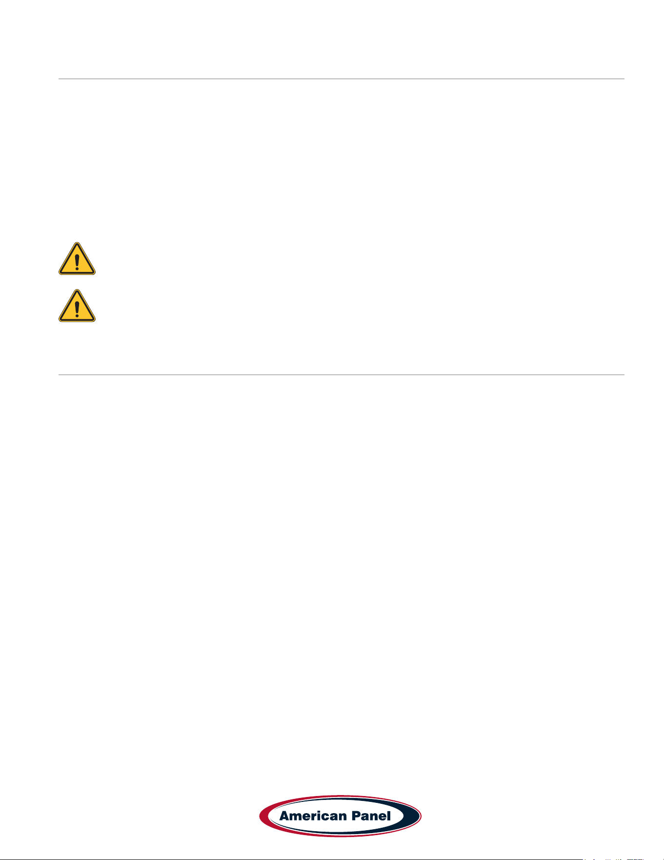
The equipment tag is located on the exterior of the unit
and displays the following information that is unique to
the unit:
• Model Number
• Serial Number
• Refrigerant Charge
• Refrigerant Pressure (Low & High)
• Electrical Volts, Phase, Hertz and Amps
• Minimum Circuit Amps
• Maximum Fuse Size (Amps)
Please have this information on hand when contacting
service or parts.
• This manual is an integral part of the product, it
supplies all of the indications necessary for correct
installation, correct use and maintenance of the
machine.
• It is mandatory for the user to read this manual
carefully and always make reference to it. It must be
kept in a place that is known and accessible to the
authorized operators (installer, user, maintenance
technician)
• The blast chiller is intended for professional use and
therefore only qualied staff can use it
• The blast chiller is destined only for the use for which it
has been designed.
• The manufacturer declines all responsibility for any
damage caused by incorrect or unreasonable use, as
for example:
• improper use by untrained staff.
• modication or interventions that are not specic for
the model.
• use of non-original spare parts or that are not
specic for the model.
• failure to comply, even partial, with the instructions
in this manual.
• The manufacturer disclaims all responsibility for
problems related to an incorrect installation of the blast
chiller.
• The blast chiller must be installed by an authorized
service/install provider.
7
5800 SE 78th St. Ocala, FL 34472
Touchscreen HURRiCHiLL Installation & Operations Manual
P: (800) 327-3015
Installation
American Panel Corporation equipment has been shipped in a package designed to sufciently protect from damage
under normal shipping circumstances. Upon receiving the shipment, carefully inspect the package for visible damage
and check the number of packages against the Bill of Lading. Notify the carrier immediately of any shortage or
damage to your shipment. Claims must be led promptly with the carrier.
After receipt of shipment, carefully and safely remove the unit from the package. Check the contents of the package
against the packing list. Under no circumstances may a damaged piece of equipment be returned to American Panel
Corporation without rst obtaining written permission.
To assure proper installation carefully read and comply with the following instructions.
WARNING - Please read the entire installation procedure before attempting to install the unit. Failure
to follow the procedures listed in this manual may result in voiding the warranty.
IMPORTANT - Due to the size and weight of this equipment, a minimum of two people are required to
install this equipment safely. All OSHA regulations must be followed while on the job site.
Installation Checklist
Check the integrity of the unit once it is unpacked.
On remote refrigeration units only, the cabinet and the condensing unit is shipped with a nitrogen charge,
Make sure the charge is still present.
Check for proper location.
• Ambient temperature no greater than 90oF (to ensure rated performance)
• Do not install near heat source
• Do not install near vapor source
• Do not install in direct sun light
• Do not install in closed areas with insufcient air change
5800 SE 78th St. Ocala, FL 34472
8
P: (800) 327-3015
Touchscreen HURRiCHiLL Installation & Operations Manual
Check for proper clearances
Reach-In Models:
• 3” clearance on the sides of the unit
• 5” clearance on the back of the unit
• Provide enough space in front to allow door opening
• Check for unobstructed air ow at the condensing unit
Roll-In Models:
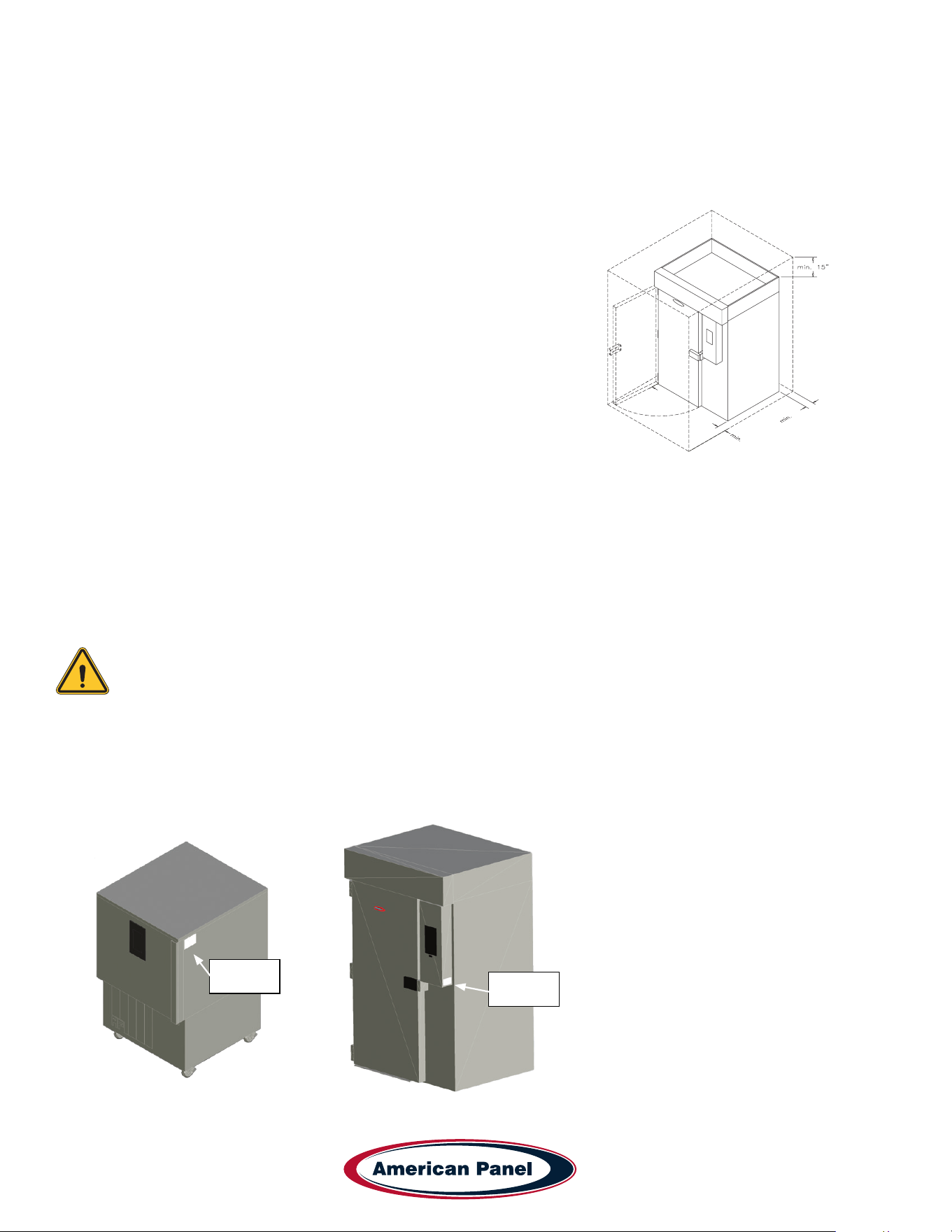
• 3” clearance on both sides of the unit (for service and door clearance)
• 15” clearance on top of the unit (for service)
• 8” clearance on the back of the unit (for service and drain hook-up)
• Provide enough space in front to allow door opening
• Check for unobstructed air ow at the condensing unit
Prepare the location.
• Check that the oor is level
• Place a layer of water resistant caulk around the perimeter of the entire footprint of the unit (roll-in units only)
• Place the unit in the chosen location and level it.
Note: Keep the unit in the upright position at all times. If you must tilt the unit for clearing door
ways, do so for a very short period of time. Once in place, keep the unit in upright position for a
period of minimum 24 hours prior to powering the unit.
Failure to comply with the above note may cause severe damage to the unit and will void the
warranty.
Verify the electrical service to be in accordance with the manufacturer label located on the right side of the
unit.
Reach-In Data
Nameplate
Location
Roll-In Data
Nameplate
Location
8”
3”
9
5800 SE 78th St. Ocala, FL 34472
Touchscreen HURRiCHiLL Installation & Operations Manual
P: (800) 327-3015
Connect the unit to the mains.
Reach-In Models:
• Plug the unit into the wall receptacle
Roll-In Models:
• Quick disconnect must be provided by the installer in close proximity to the unit
• The electrical connection must be carried out by a licensed electrician
• The electrical J-Box (6 1/4” x 3 1/8”) is located on the top of the unit towards the front.
• On remote refrigeration models the cabinet and the condensing unit require separate electrical power supplies.
Condensate Drainage
Reach-In Models:
• Install drain pan or drain line. Install the drain pan by sliding the pan on the guides located on the bottom of the
unit.
• When installing the drain line the drainage connection must be carried out in conformity with the local regulation.
As a standard conguration, all reach-in Hurrichill units are provided with ¾” ID exible tubing drain line.
Roll-In Models:
• The drainage connection must be carried out in conformity with the local regulations.
• As a standard conguration, all roll-in / self-contained Hurrichill units are provided with 1” FPT union at the back
of the unit.
Install wire shelves (if so equipped).
Operate the unit in Hard Chill / Manual mode for approximately 20 minutes to verify temperature pull down, see
chapter Unit Operation – Manual Mode any Cycle.
Verify proper airow direction.
• Evaporator – front to back
• Condenser – front to back
Note: American Panel Corporation blast chillers are equipped with a short cycle protection. If the
unit is stopped or the door is opened and closed during a chilling cycle more than once, the
compressor will not start for a period of 3 to 5 minutes.
Inspect liquid-line sight glass to ensure is clear and dry.
When possible, inspect the oil level within the compressor, minimum ½ full on level indicator window.
Engage, operate and verify effectiveness of manually engaged defrost cycle, see chapter Unit Operation –
Defrost Cycle.
Note: The blast chiller is programmed, from the factory, to automatically engage the defrost cycle at
12:00 AM every morning. The defrost cycle will not engage unless is needed and the unit is in
stand-by mode (no other cycle engaged). To change the time or to disable the automatically engaged
defrost cycle see chapter Customizing the Cycles.
5800 SE 78th St. Ocala, FL 34472
10
P: (800) 327-3015
Touchscreen HURRiCHiLL Installation & Operations Manual
Setup and verify the PC connection (if so equipped), see chapter PC Package. IT personnel may be needed.
Inform the factory if any functional and performance issues were found following the completion of the above
tests.
Verify that the operator has all necessary operation manuals, menus and instructions. Contact factory with any
questions, Monday-Friday 8:00 a.m. to 5:00 p.m. ET at 800-327-3015 or consult the website at
www.americanpanel.com
Specications and Performance
Blast chilling - Capable of lowering the core temperature of product from 160˚F to 38˚F within 90 minutes.
Shock freeze - Capable of lowering the core temperature of product from 160˚F to 0˚F within 240 minutes.
Model Type
Pan Capacity
Sheet/Steam
Chilling Capacity
(90 min)
Freezing Capacity
(240 min)
AP7BCF70-2-P Blast Chiller/Shock Freezer 7/14 70 70
AP7BCF70-2-C-P Blast Chiller/Shock Freezer 7/7 70 70
AP10BCF100-2-P Blast Chiller/Shock Freezer 0/10 100 60
AP12BCF150-2-P Blast Chiller/Shock Freezer 12/24 150 150
AP20BCF200-3-P Blast Chiller/Shock Freezer 10/20 200 120
* Standard conguration sized for 202 Rational rolling rack. other combi congurations are available; consult factory for details.
Note: Each unit was designed for a specic product capacity as shown above. Overloading the unit
could signicantly reduce its service life.
11
5800 SE 78th St. Ocala, FL 34472
Touchscreen HURRiCHiLL Installation & Operations Manual
P: (800) 327-3015
Modes Explained
Each unit is capable of running in either an ‘Automatic’, ‘Manual’ or ‘A la Carte’ mode:
• In ‘Automatic’ mode the unit will read the food temperature via the food probe and adjust the air temperature
accordingly.
NOTE: When using ‘Automatic’ mode it is very important to insert the food probe in the product.
The food probe must read the core temperature of the product in order for the unit to work as
intended.
• In ‘Manual’ mode the air within the cabinet will be held at a preset temperature for a preset amount of time based
on the selected operating cycle (see below).
• In ‘A la Carte’ mode the air within the cabinet will be held at a preset temperature until all of the timers expire.
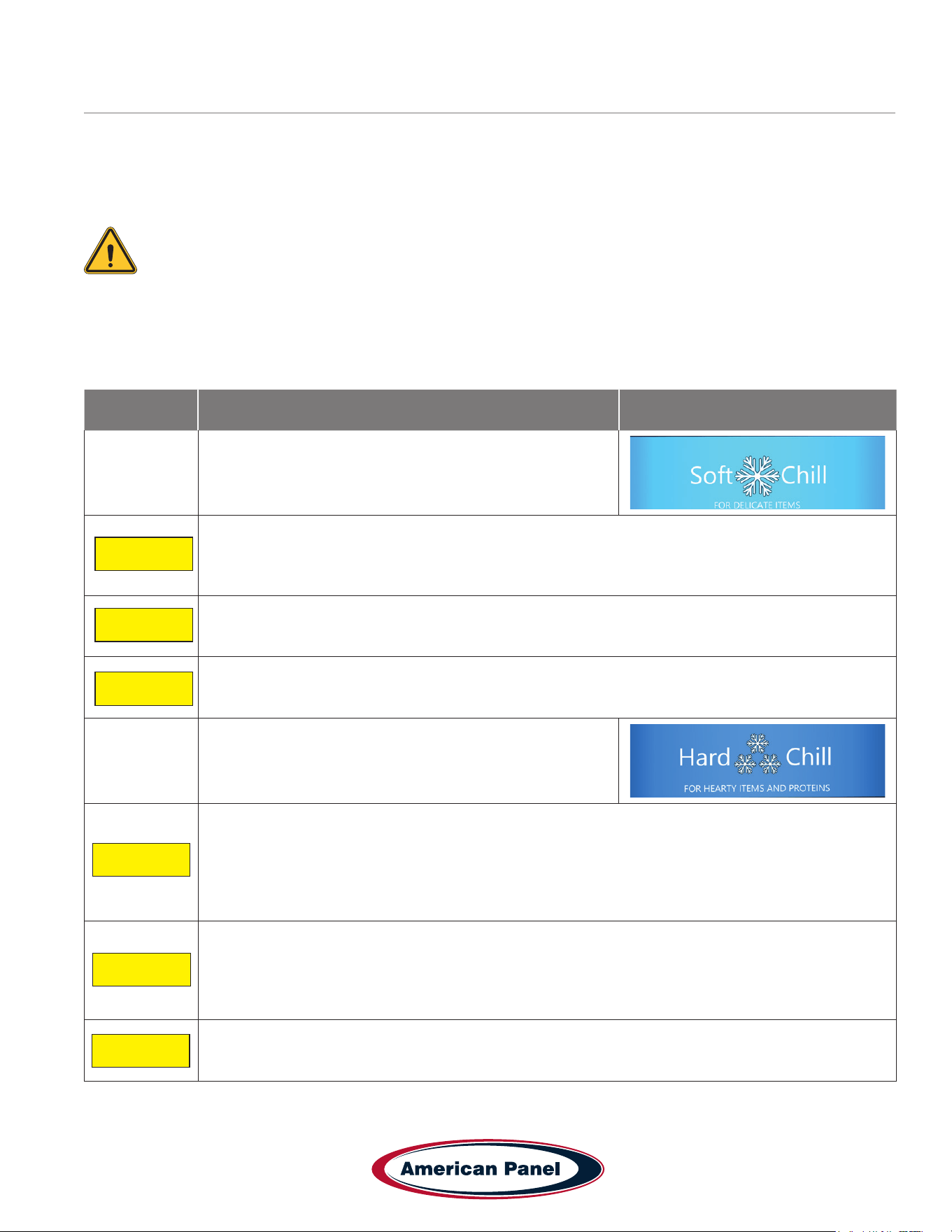
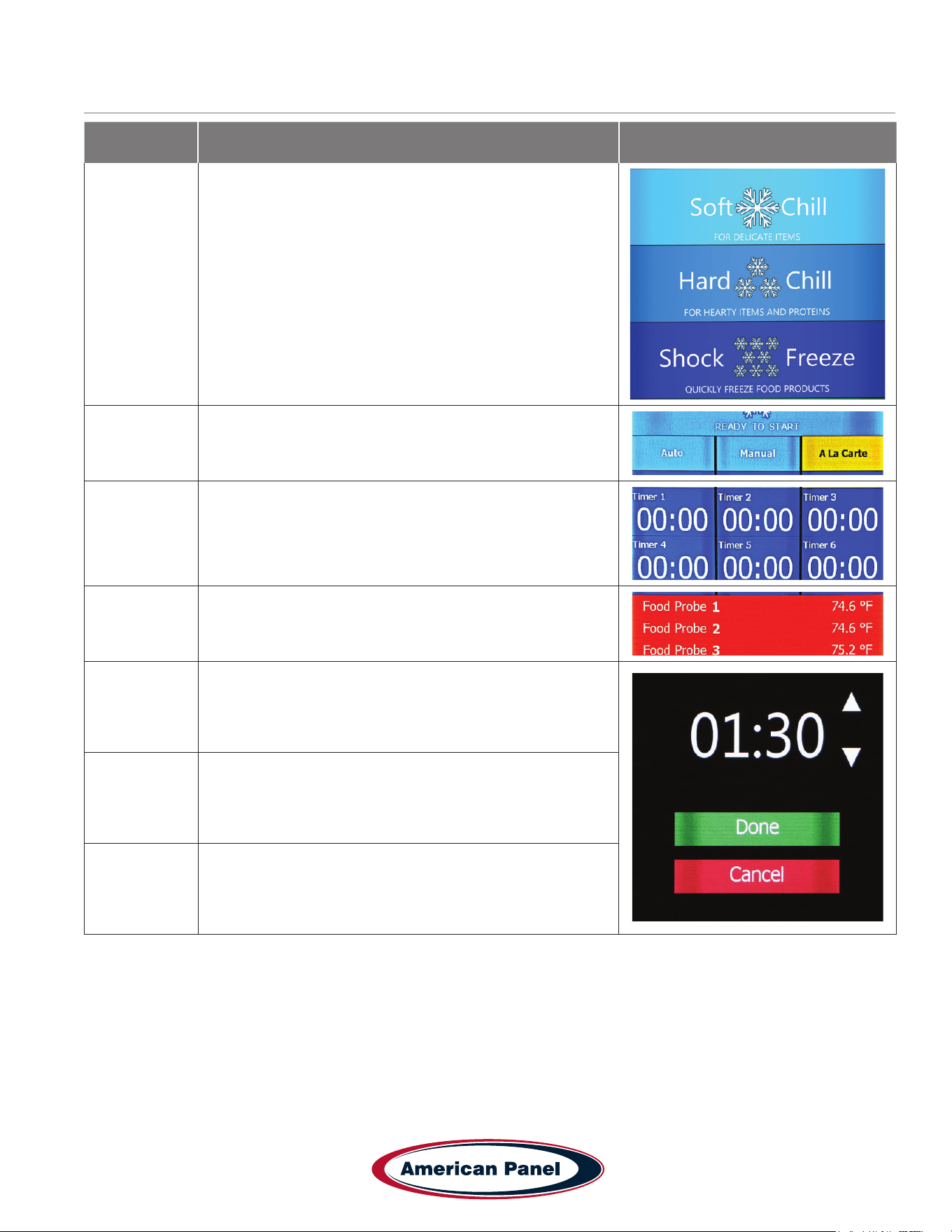
Cycle Description Button (icon)
Soft Chill
Used for delicate items and salad items. Items with low fat
or moisture content such as bakery goods should also use
this mode.
Automatic Mode: The air temperature will cycle between 28°F and 35°F until the food core
temperature will reach 40°F, at this point the blast chiller will switch into holding mode where the
air temperature will cycle between 35°F and 42°F until the food is removed from the cabinet and/or
cycle is stopped by the operator.
Manual Mode: The air temperature will cycle between 28°F and 35°F for 1.5 hours. After 1.5 hours
the unit will switch into holding mode where the air temperature will cycle between 35°F and 42°F
until the food is removed from the cabinet and/or cycle is stopped by the operator.
A La Carte: The air temperature will cycle between 28°F and 35°F until all the timers expire, after
that the unit will switch into holding mode where the air temperature will cycle between 35°F and
42°F until the cycle is manually stopped by the operator.
Hard Chill
Used for all foods. Some freezing on the food surface
may occur, especially with thicker products; if this is not
acceptable use the ‘Soft’ cycle as described above.
Automatic Mode: The air temperature will cycle between 0°F and 10°F until the food core
temperature will reach 60°F (rst part of the cycle). After the food core temperature reaches 60°F
the air temperature inside the unit will cycle between 28°F and 35°F (second part of the cycle) until
the food core temperature will reach 40°F. At this point the blast chiller will switch into holding mode
where the air temperature will cycle between 35°F and 42°F until the food is removed from the
cabinet and/or cycle is stopped by the operator.
Manual Mode: The air temperature will cycle between 0°F and 10°F for one hour (rst part of
the cycle). After one hour the air temperature inside the unit will cycle between 28°F and 35°F for
another hour (second part of the cycle). At this point the blast chiller will switch into holding mode
where the air temperature will cycle between 35°F and 42°F until the food is removed from the
cabinet and/or cycle is stopped by the operator.
A La Carte: The air temperature will cycle between 0°F and 10°F until all the timers expire, after
that the unit will switch into holding mode where the air temperature will cycle between 35°F and
42°F until the cycle is manually stopped by the operator.
Auto
Manual
A La Carte
Auto
Manual
A La Carte
5800 SE 78th St. Ocala, FL 34472
12
P: (800) 327-3015
Touchscreen HURRiCHiLL Installation & Operations Manual
Cycle Description Button (icon)
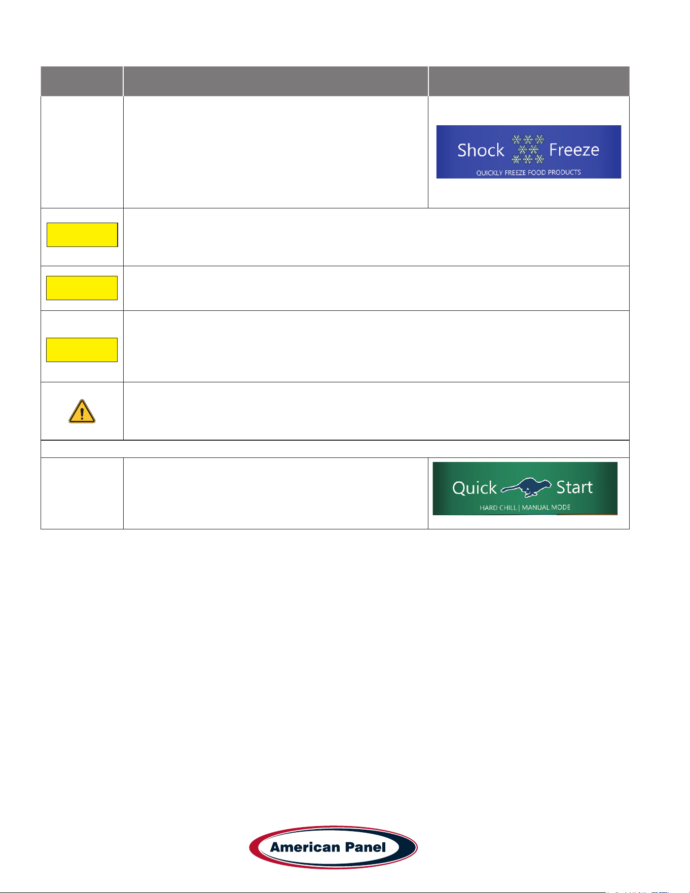
Shock Freeze
Use for all freezing needs. When using the Shock Freezing
Cycle the ice crystals that form within the product are
very small. The quality and the texture of the product is
preserved. For that reason, the Shock Freeze Cycle is
suitable even for delicate products such as sushi meat and
prime meat cuts. Shock Freeze Cycle will give excellent
results when used in the process of Ice Cream and Gelato
hardening, it will give a smooth texture to the product.
Automatic Mode: The air temperature will cycle between -25°F and -15°F until the food core
temperature will reach 0°F, at this point the blast chiller will switch into holding mode where the air
temperature will cycle between -4°F and 3°F until the food is removed from the cabinet and/or cycle
is stopped by the operator.
Manual Mode: The air temperature will cycle between -25°F and -15°F for 4 hours. After 4 hours
the unit will switch into holding mode where the air temperature will cycle between -4°F and 3°F
until the food is removed from the cabinet and/or cycle is stopped by the operator.
A La Carte: The air temperature will cycle between -25°F and -15°F until all the timers expire, after
that the unit will switch into holding mode where the air temperature will cycle between -4°F and 3°F
until the cycle is manually stopped by the operator.
NOTE: At the end of any cycle the unit will switch into holding mode to maintain the food
at a specic temperature. However, the unit is not designed to be a refrigerator or holding
cabinet. Do not allow the blast chiller to function in holding mode for extended periods of
time.
Occasional overnight holding is allowed.
Quick Start
The Quick Start mode allows for one button operation of
the most common cycle as dened by the user. Quick
Start is set from the factory as a Soft Chill - Manual
mode but can be customized in the settings for any cycle
operation.
Auto
Manual
A La Carte
13
5800 SE 78th St. Ocala, FL 34472
Touchscreen HURRiCHiLL Installation & Operations Manual
P: (800) 327-3015
Cycle Description Button (icon)
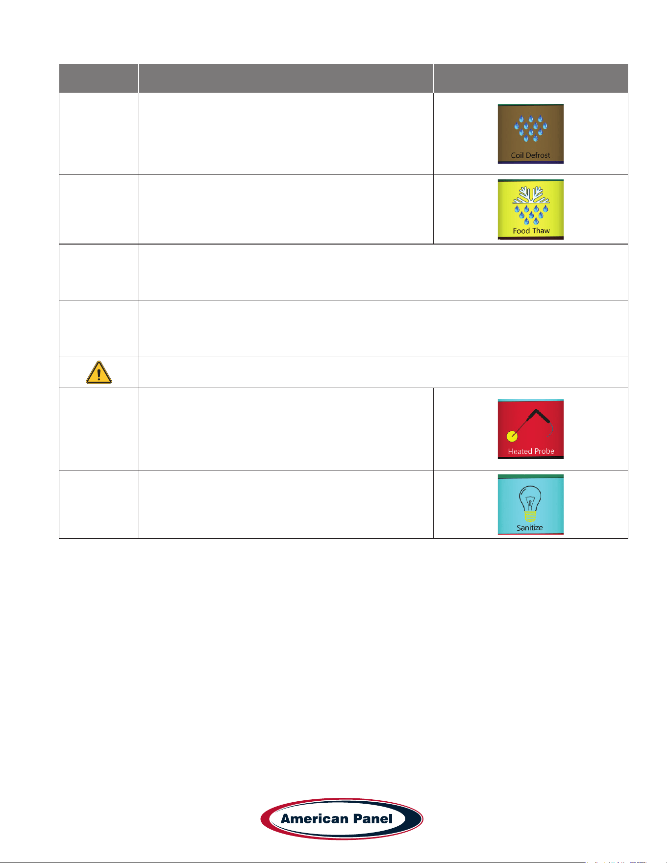
Defrost
Use this mode to defrost the evaporator coil. The defrost
cycle must be manually engaged (see controller operation
below). Defrost the unit once a day or as needed. Ice
build-up can be observed by looking thru the fan grill at the
evaporator coil. The factory preset for the Defrost Cycle is
30 minutes.
Thaw Cycle
(if equipped)
Use to thaw frozen products. Units equipped with the
Thaw feature will be delivered with a special thaw probe, a
cordless drill and a sanitary drill bit. Use the cordless drill
and sanitary drill bit to provide a hole to probe the frozen
product.
Automatic Mode: The air temperature will cycle between 42°F and 50°F until the food temperature,
as recorded by the thaw probe, will reach 32°F; at this point the blast chiller will switch into holding
mode where the air temperature will cycle between 35°F and 42°F until the food is removed from
the cabinet and/or cycle is stopped by the operator.
Manual Mode: The air temperature will cycle between 42°F and 50°F for a preset amount of time,
set by the operator at the time of starting the cycle. After the cycle time expires, the unit will switch
into holding mode where the air temperature will cycle between 35°F and 42°F until the food is
removed from the cabinet and/or cycle is stopped by the operator.
NOTE: When probing for thaw cycle, use the drill bit to provide a hole in the frozen product.
Heated Probe
(if equipped)
Use the Heated Probe feature prior to extracting the
temperature probe from the frozen product. Gentle heat
will be applied to the food probe for 5 seconds to facilitate
the extraction of the probe. The Heated Probe will run only
if the temperature at the food probe is below 30°F. Repeat
the heated probe cycle if needed.
Sanitize
(if equipped)
5800 SE 78th St. Ocala, FL 34472
14
P: (800) 327-3015
Touchscreen HURRiCHiLL Installation & Operations Manual
Factory Presets Automatic Mode - Quick Reference Chart
Cycle
Setting
Low Air
Part 1
High Air
Part 1
Breaking
Temp.
Low Air
Part 2
High Air
Part 2
End Food
Temp.
Low Air
Holding
High Air
Holding
Soft 28˚F 35˚F NA NA NA 40˚F 35˚F 42˚F
Hard (Chillers Only) 10˚F 20˚F 60˚F 28˚F 35˚F 40˚F 35˚F 42˚F
Hard (Chillers &
Freezers)
0˚F 10˚F 60˚F 28˚F 35˚F 40˚F 35˚F 42˚F
Shock Freeze -25˚F 15˚F NA NA NA 0˚F -4˚F 3˚F
Thaw 42˚F 50˚F NA NA NA 32˚F 35˚F 42˚F
Factory Presets Manual Mode - Quick Reference Chart
Cycle
Setting
Low Air
Part 1
High Air
Part 1
Time
Part 1
Low Air
Part 2
High Air
Part 2
Time
Part 2
Low Air
Holding
High Air
Holding
Soft 28˚F 35˚F NA NA NA 90 Min 35˚F 42˚F
Hard (Chillers Only) 10˚F 20˚F 60 Min 28˚F 35˚F 60 Min 35˚F 42˚F
Hard (Chillers &
Freezers)
0˚F 10˚F 60 Min 28˚F 35˚F 60 Min 35˚F 42˚F
Shock Freeze -25˚F 15˚F NA NA NA 240 Min -4˚F 3˚F
Thaw 42˚F 50˚F NA NA NA Set at Start 35˚F 42˚F
15
5800 SE 78th St. Ocala, FL 34472
Touchscreen HURRiCHiLL Installation & Operations Manual
P: (800) 327-3015
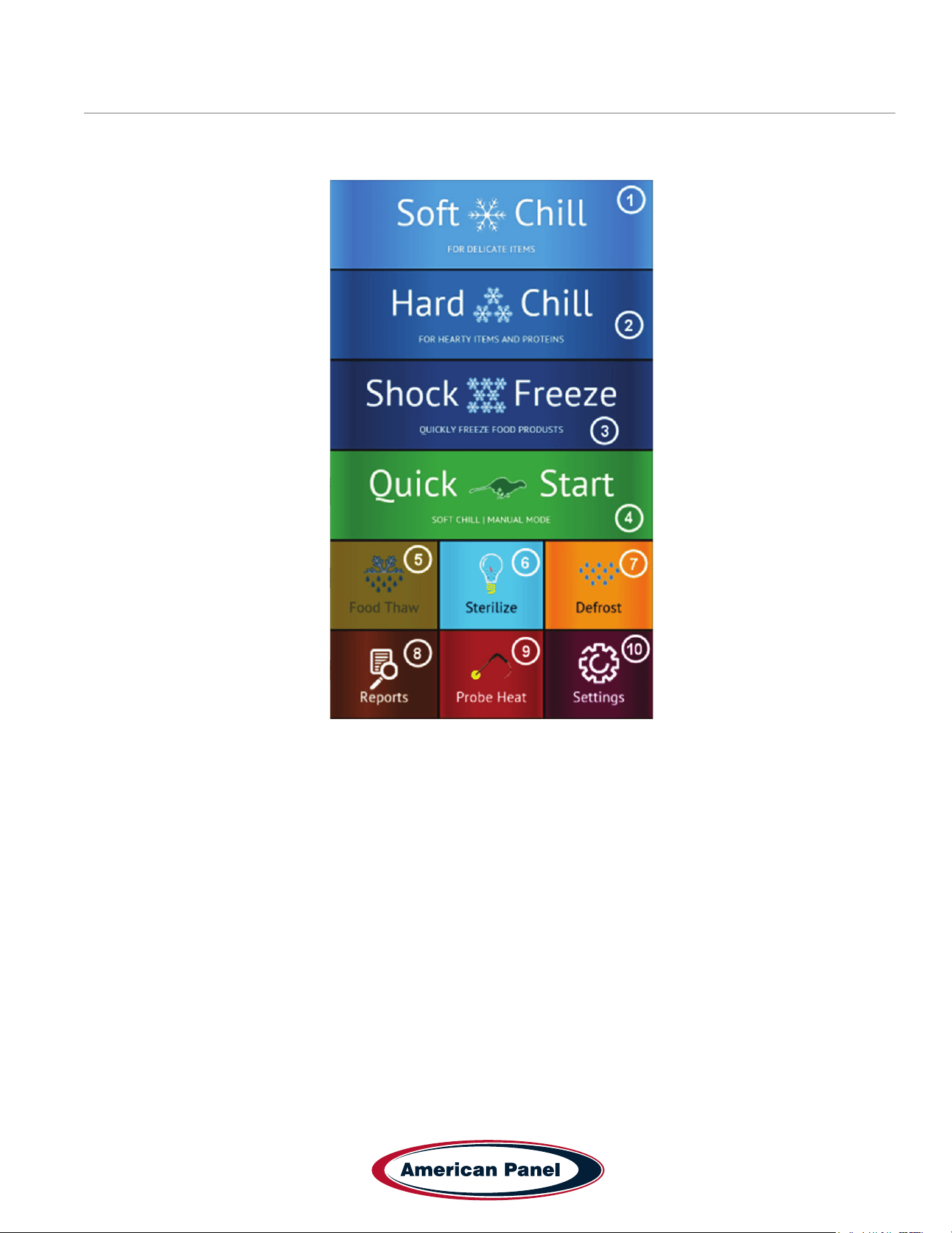
Home Screen
The home screen can be accessed by taping on the blank display, if the display is off, or by pressing the home button,
if the controller is in one of the cycle screens.
1) Soft Chill Button – Press to access Soft Chill Cycle Menu
2) Hard Chill Button – Press to access Hard Chill Cycle Menu
3) Shock Freeze Button – Press to access Shock Freeze Cycle Menu
4) Quick Start Button – Press to engage the preset cycle, the Quick Start Button is set from the factory to engage
the Soft Chill cycle in Manual Mode. The operator can set the Quick Start Button to engage the desired cycle, see
Settings -> Quick Start.
5) Food Thaw Button – Press to access Food Thaw Cycle Menu. Food Thaw Cycle is an optional cycle and is
available on selected models only.
6) Sanitize Button – Press to access the Sanitize Cycle Menu. Sanitize Cycle is optional and is available on
selected models only. Sanitize Cycle will sanitize the interior of the cabinet. Sanitize Cycle can be set to engage
automatically at preset times of the day when unit not in use, see Settings -> Sanitize.
7) Defrost Cycle Button – Press to access the Defrost Cycle Menu. Defrost Cycle can be set to engage
automatically at preset times of the day when unit not in use, see Settings -> Defrost.
8) Reports Button – Press to access the HACCP reports preview menu.
9) Probe Heat Button – Press to choose which food probe to heat for easier extraction from the frozen product.
10) Settings Button – Press to access the settings menu.
5800 SE 78th St. Ocala, FL 34472
16
P: (800) 327-3015
Touchscreen HURRiCHiLL Installation & Operations Manual
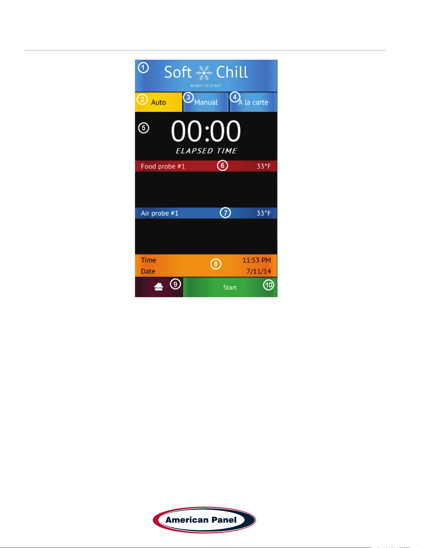
Automatic Mode Screen
1) Status Label – Displays the selected cycle and the status of the cycle.
Status:
READY TO START – unit in standby mode waiting for the user to make a selection such as Start
CYCLE IN PROGRESS – the chilling cycle is in progress
COMPLETED – the chilling cycle has been completed and the unit is maintaining the product at safe holding
temperatures
2) Auto Mode Button – Press to select the automatic blast chilling mode.
3) Manual Mode Button – Press to switch to the manual blast chilling mode.
4) A la carte Mode Button – Press to switch to the A la carte blast chilling mode.
5) ELAPSED TIME Label – Displays the elapsed time form the start of the cycle.
6) Food probe #... Label/Button – Press to assign to the current probe the food ID that it monitors. The assigned
food ID will show on the HACCP reports. The label of Food probe #... will display the temperature of the probe.
One food probe is the standard conguration for all American Panel Corporation blast chillers, the controller
supports up to 4 food probes.
7) Air probe #... Label – Displays the air temperature inside the cabinet. Double and triple depth cabinet models will
have two and three air probes respectively, one for each cabinet.
8) Time and Date Label – Displays the current date and time.
9) Home Button – Press to stop the current cycle and switch to the home screen.
10) Start/Stop Button – Press to start or stop the cycle. If the stop button will be pressed during the cycle a
conrmation screen will prompt the user to conrm the choice.
17
5800 SE 78th St. Ocala, FL 34472
Touchscreen HURRiCHiLL Installation & Operations Manual
P: (800) 327-3015
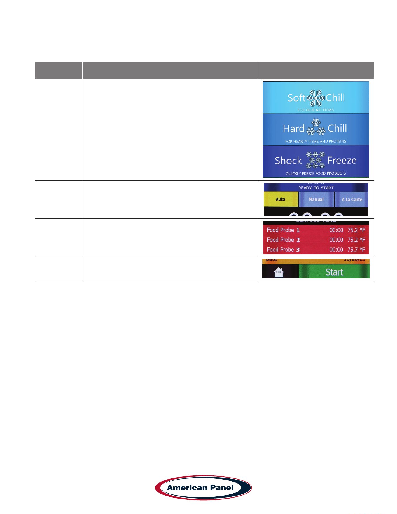
How to Start a Cycle in Automatic Mode
Step Description Action
1
Choose Soft Chill, Hard Chill or Shock Freeze from the
Home screen
2
Make sure Auto tab is selected
(For the Auto mode to work as intended the food probe
must be inserted into the product)
3
Optional: press Food Probe # to assign a Food ID to the
Probe. Choose from a set list of Food IDs or enter your
own name.
4 Press start to start the cycle
5800 SE 78th St. Ocala, FL 34472
18
P: (800) 327-3015
Touchscreen HURRiCHiLL Installation & Operations Manual
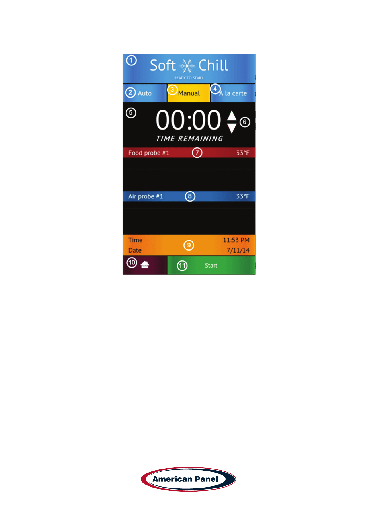
Manual Mode Screen
1) Status Label – Displays the selected cycle and the status of the cycle
Status:
READY TO START – unit in standby mode waiting for the user to make a selection such as Start
CYCLE IN PROGRESS – the chilling cycle is in progress
COMPLETED – the chilling cycle has been completed and the unit is maintaining the product at safe holding
temperatures
2) Auto Mode Button – Press to select the automatic blast chilling mode.
3) Manual Mode Button – Press to switch to the manual blast chilling mode.
4) A la carte Mode Button – Press to switch to the A la carte blast chilling mode.
5) TIME REMAINING Label – Indicates the remaining time to the end of the cycle.
6) UP/DOWN BUTTONS – Press to adjust the cycle time as needed.
7) Food probe #... Label/Button – Press to assign to the current probe the food ID that it monitors. The assigned
food ID will show on the HACCP reports. The label of Food probe #... will display the temperature of the probe.
One food probe is the standard conguration for all American Panel Corporation blast chillers, the controller
supports up to 4 food probes.
8) Air probe #... Label – Displays the air temperature inside the cabinet. Double or triple depth cabinet models will
have two or three air probes respectively, one for each cabinet.
9) Time and Date Label – Displays the current date and time.
10) Home Button – Press to stop the current cycle and switch to the home screen.
11) Start/Stop Button – Press to start or stop the cycle. If the stop button will be pressed during the cycle a
conrmation screen will prompt the user to conrm the choice.
19
5800 SE 78th St. Ocala, FL 34472
Touchscreen HURRiCHiLL Installation & Operations Manual
P: (800) 327-3015
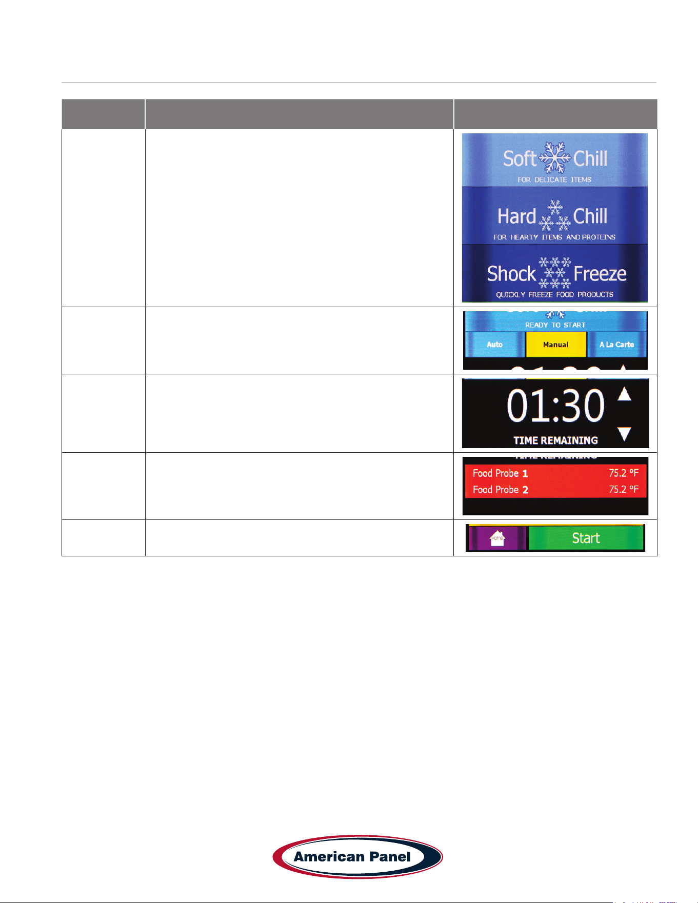
How to Start a Cycle in Manual Mode
Step Description Action
1
Choose Soft Chill, Hard Chill or Shock Freeze from the
Home screen
2 Make sure Manual tab is selected
3
Optional: Press up or down on the time arrows to adjust
the cycle time
4
Optional: press Food Probe # to assign a Food ID to the
Probe. Choose from a set list of Food IDs or enter your
own name.
5 Press start to start the cycle
5800 SE 78th St. Ocala, FL 34472
20
P: (800) 327-3015
Touchscreen HURRiCHiLL Installation & Operations Manual
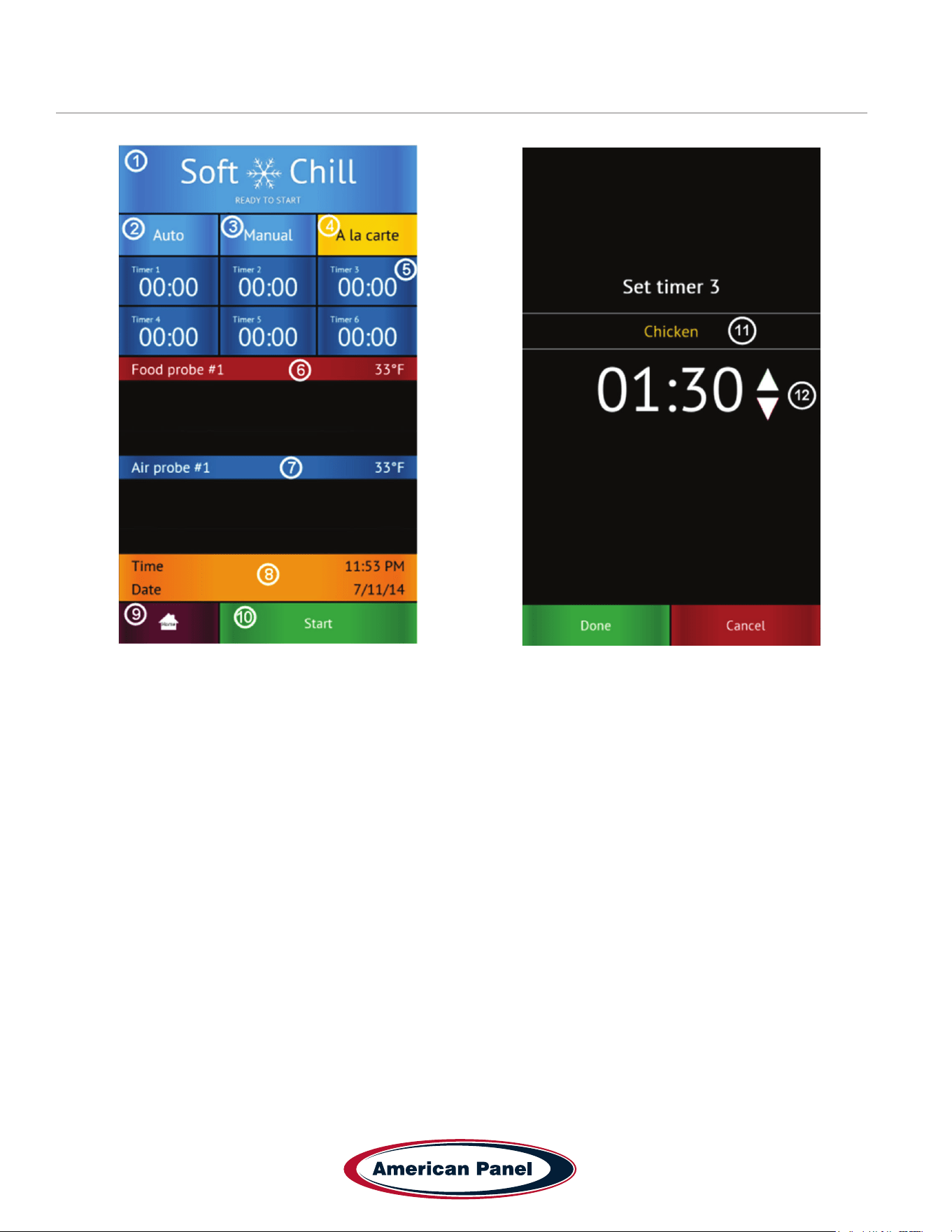
A La Cart Mode Screen & Timer Screen
1) Status Label – Displays the selected cycle and the status of the cycle
Status:
READY TO START – unit in standby mode waiting for the user to make a selection such as Start
CYCLE IN PROGRESS – the chilling cycle is in progress
COMPLETED – the chilling cycle has been completed and the unit is maintaining the product at safe holding
temperatures
2) Auto Mode Button – Press to select the automatic blast chilling mode.
3) Manual Mode Button – Press to switch to the manual blast chilling mode.
4) A la carte Mode Button – Press to switch to the A la carte blast chilling mode.
5) Timer Buttons/Labels – Press to access the timer setting screen. The timer label will indicate the remaining time
and the product name of the food it monitors.
6) Food probe #... Label - The label of Food probe #... will display the temperature of the probe. One food probe is
the standard conguration for all American Panel blast chillers, the controller supports up to 4 food probes.
7) Air probe #... Label – Displays the air temperature inside the cabinet. Double or triple depth cabinet models will
have two or three air probes respectively, one for each cabinet.
8) Time and Date Label – Displays the current date and time.
9) Home Button – Press to stop the current cycle and switch to the home screen.
10) Start/Stop Button – Press to start or stop the cycle. If the stop button will be pressed during the cycle a
conrmation screen will prompt the user to conrm the choice.
11) Set Timer Id Button – Press to assign a food id. to the current timer.
12) Up/Down Buttons – Press to adjust the timer.
21
5800 SE 78th St. Ocala, FL 34472
Touchscreen HURRiCHiLL Installation & Operations Manual
P: (800) 327-3015
How to Start a Cycle in A La Cart Mode
Step Description Action
1
Choose Soft Chill, Hard Chill or Shock Freeze from the
Home screen
2 Make sure A la carte tab is selected
3
Select any available timer. Available timers are the ones
set at 00:00 and have not yet been activated.
4
Optional: Press Food ID to assign a Food ID to the timer.
Choose from a preset list of IDs or enter your own.
5
Press up or down on the time arrows to adjust the cycle
time
6 Press Done to start the cycle
Up to 6 timers can be added in the A la carte mode.
5800 SE 78th St. Ocala, FL 34472
22
P: (800) 327-3015
Touchscreen HURRiCHiLL Installation & Operations Manual
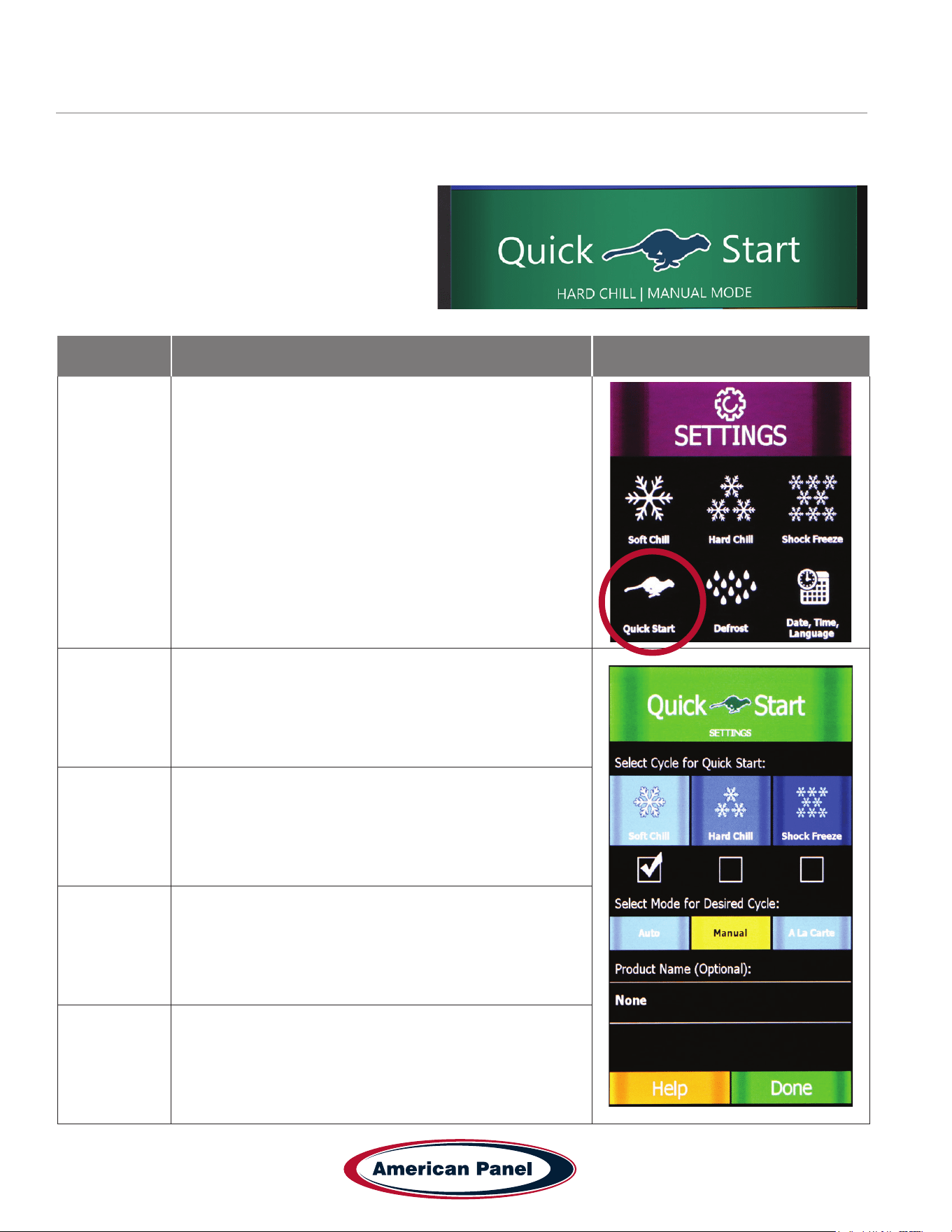
How to Start a Cycle in Quick Start Mode & Customizing Quick Start
The Quick Start mode allows for one button operation of the most common cycle as dened by the user. Quick Start
is set from the factory as a Soft Chill - Manual mode but can be customized in the settings for any cycle operation.
Press the Quick Start button to engage the preset
cycle
To customize the Quick Start button, follow the steps
below.
Step Description Action
1
To customize the cycle and mode that the Quick Start
button engages, select Settings from the home screen and
then Quick Start.
2 Select the Cycle (Soft Chill, Hard Chill or Shock Freeze)
3 Select the Mode (A la cart, manual or automatic)
4
Enter a product name (Optional) from a list of items, or
enter your own on the screen.
5 Select Done to save your settings.
23
5800 SE 78th St. Ocala, FL 34472
Touchscreen HURRiCHiLL Installation & Operations Manual
P: (800) 327-3015
PC Connection Package
Connect to Controller - Direct Connection
The optional wireless pc communication package features:
• HACCP data download via local Wi-Fi network or peer-to-peer connection
• Remote blast chiller monitoring via Wi-Fi network
• E-mail notications
The optional wireless pc communication package is required to connect to the controller.
The controller is set from the factory as a Wi-Fi access point. In this conguration the controller broadcasts an SSID
such as blast-chiller-xxxxxxxxxxx-wha.
Step Description Action
1
Open the Wi-Fi connections on the device you want to use
to access the controller
2
Connect to the SSID of the unit -
blast-chiller-xxxxxxxx-wha is the SSID that is set from the
factory. If this has been previously customized, use the
current SSID in the system.
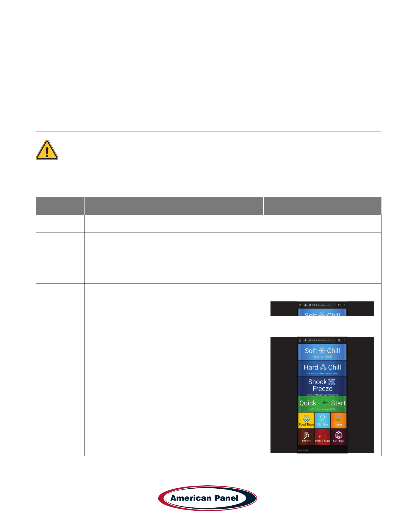
3
Open a web browser on the device and enter 192.168.1.1
into the address bar.
4
The home screen of the controller should show up in the
browser window. You are now able to download HACCP
data, monitor the blast chiller modes and set up any
notication settings.
5800 SE 78th St. Ocala, FL 34472
24
P: (800) 327-3015
Touchscreen HURRiCHiLL Installation & Operations Manual
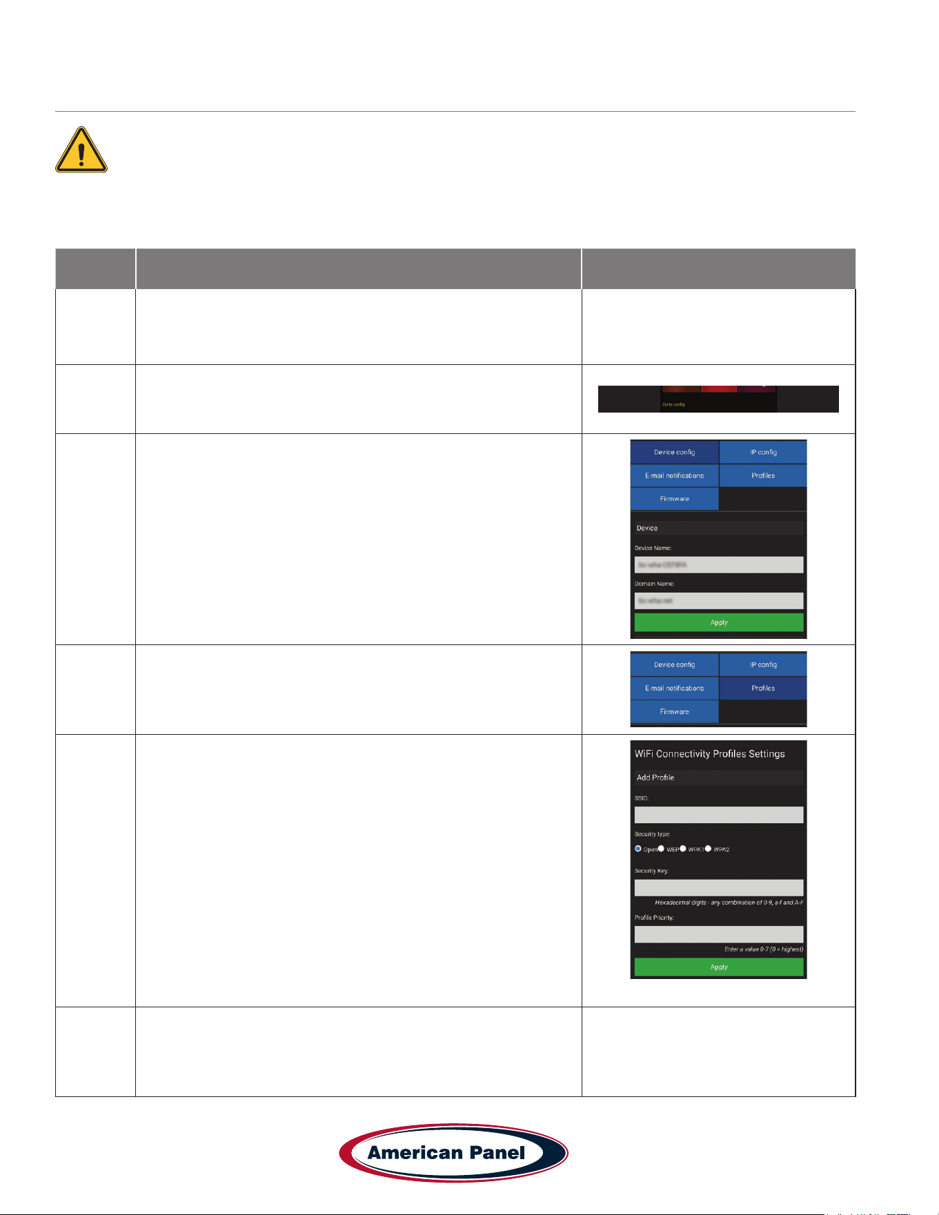
Connect to Controller - Wi-Fi
The optional wireless pc communication package is required to connect to the controller.
The controller is set from the factory as a Wi-Fi access point. In this conguration the controller broadcasts an SSID
such as blast-chiller-xxxxxxxxxxx-wha.
Step Description Action
1
Connect to the controller through the Direct Connection steps
outlined on pg 28. Once connected on a browser, complete the
steps below
2 Press the “Go to cong” button at the bottom of the screen.
3
Make sure the “Device cong” tab is selected
Enter the desired name for your HURRiCHiLL device.
4 Select the “Proles” tab
5
Enter the SSID for your wi- network
Choose the correct security type for your network
Enter your network security key (password)
Enter 0 in Prole Priority
Click the “Apply” button to save all the changes
Click the “Go to application” button to go back to the main
screen.
6
Reset power to the unit and allow few minutes for the controller
to connect to the Wi-Fi network.
25
5800 SE 78th St. Ocala, FL 34472
Touchscreen HURRiCHiLL Installation & Operations Manual
P: (800) 327-3015
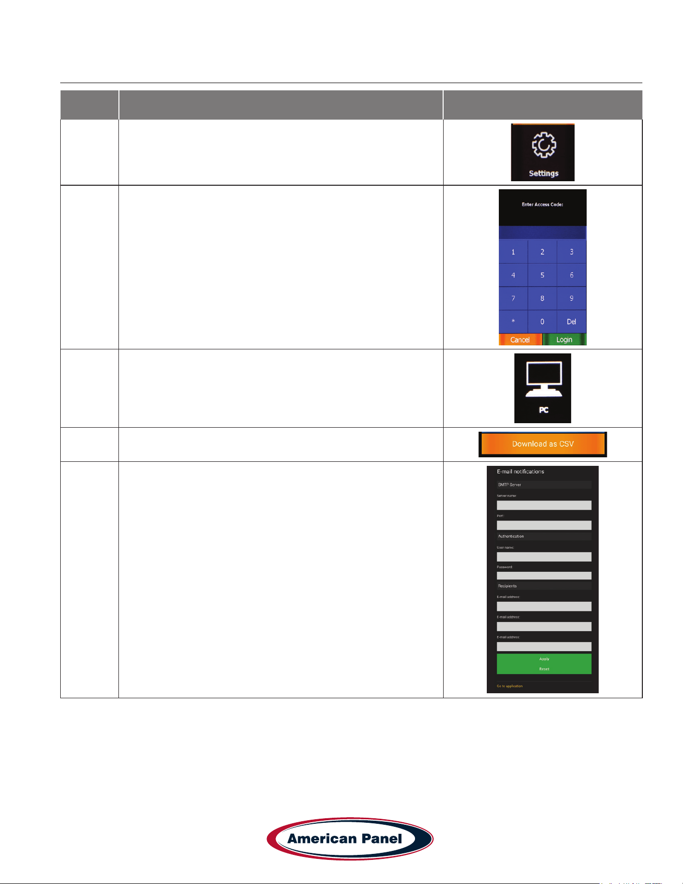
Step Description Action
7
Once the unit has restarted, Check the wi- settings by
selecting the Settings button on the home screen of the unit.
8 Enter the controller password and hit done
9 Press the PC button to access the wi- settings
10 Press the Wi-Fi Conguration button
11
A list of settings will be shown including Name, SSID it is
connected to and IP Address.
Your unit is now set up for wireless access.
Connect to Controller - Wi-Fi continued
5800 SE 78th St. Ocala, FL 34472
26
P: (800) 327-3015
Touchscreen HURRiCHiLL Installation & Operations Manual
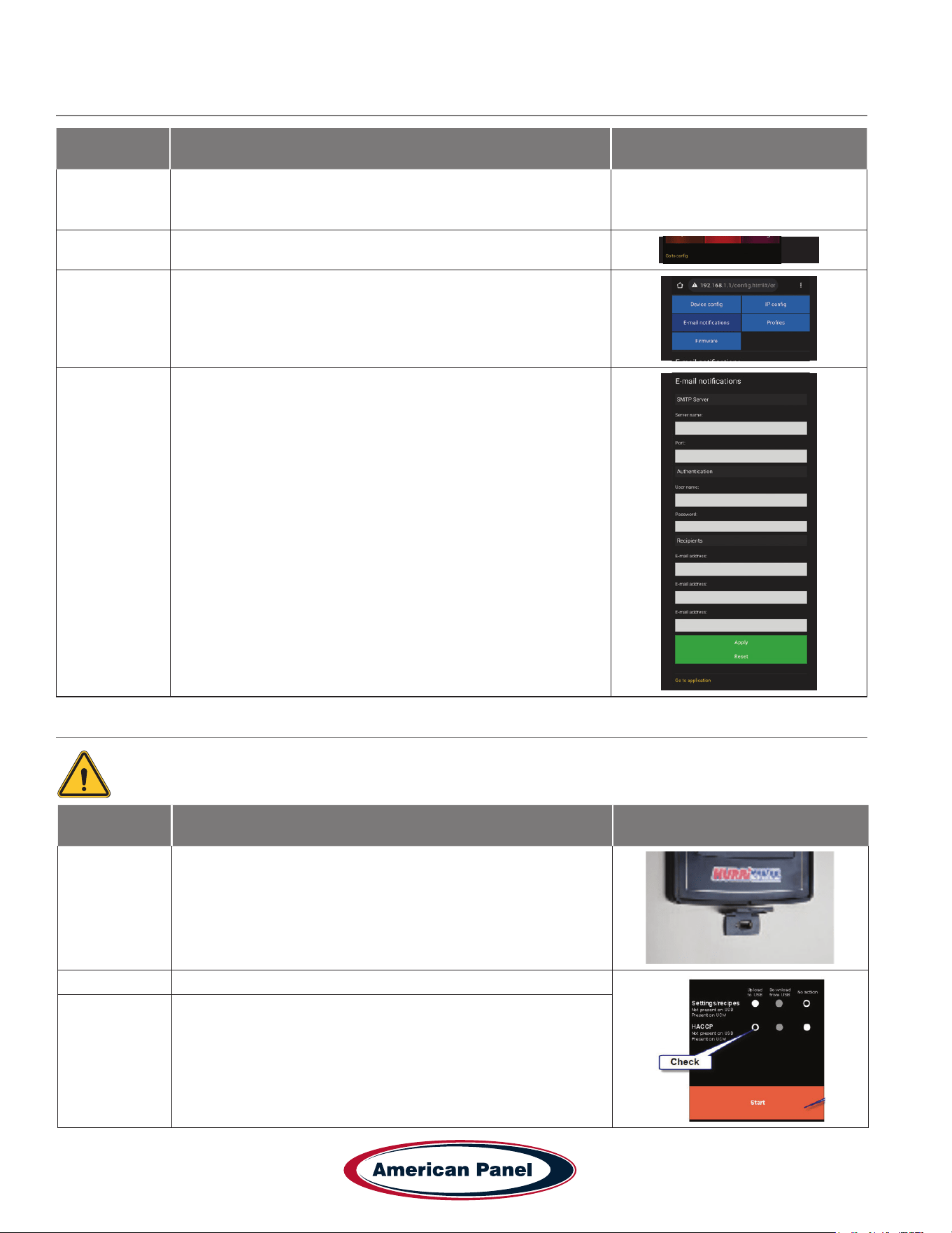
Connect to Controller - Wi-Fi notications setup
Step Description Action
1
Connect to the controller through the Direct Connection steps
outlined on pg 28. Once connected on a browser, complete
the steps below
2 Press the “Go to cong” button at the bottom of the screen.
3 Make sure the “Email Notications” tab is selected
4
Enter the info for the elds below:
• STP server name
• Port type
• Email address notications will come FROM
• Email account password
• Email recipient - you can add up to 3 emails to send TO
• Clink “Apply” when done
• Click “Go to Application” to exit
HACCP Data Download via USB
The optional USB pc communication package is required to connect to the controller.
Step Description Action
1
Note: The HURRiCHiLL touchscreen controllers support only USB
2.0 ash drives formatted with the FAT32 le system. Other USB
versions or le system formats are not recognized or supported.
Insert a usb drive into the controller port shown.
2 Check the settings on screen for the data needed.
3 Press “Start” to download the le.
27
5800 SE 78th St. Ocala, FL 34472
Touchscreen HURRiCHiLL Installation & Operations Manual
P: (800) 327-3015
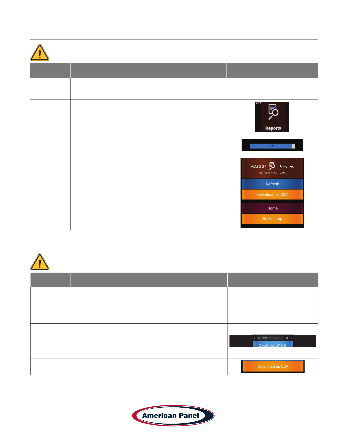
HACCP Data Download via Peer to Peer
HACCP Data Download via Wi-Fi
The optional wireless pc communication package is required to connect to the controller.
The optional wireless pc communication package is required to connect to the controller.
Step Description Action
1
Connect to the controller through the Direct Connection steps
outlined on pg 28. Once connected on a browser, complete
the steps below
2
Press the “Reports” button on the home screen in your
browser.
3
Click Refresh to load the most current data. Wait until the
refresh is complete - the bar will hit 100% and you will see the
updated data on screen.
4
Click the Download button to download the HACCP data as a
CSV le to your device.
Step Description Action
1
Make sure the blast chiller is connected to a local wi-
network as outlined on section “ Connect to Controller - Wi-Fi”
Make note of the IP address of the machine.
Connect the device to the same wi- network as the blast
chiller.
2
Enter the blast chiller IP address from step 1 into a browser
on your device. This will connect to the unit over wi- and
show the blast chiller home screen.
3
Follow the steps in “HACCP Data Download via Peer to Peer”
to download the data to your device.
5800 SE 78th St. Ocala, FL 34472
28
P: (800) 327-3015
Touchscreen HURRiCHiLL Installation & Operations Manual
Customizing the Cycles and Technical Settings
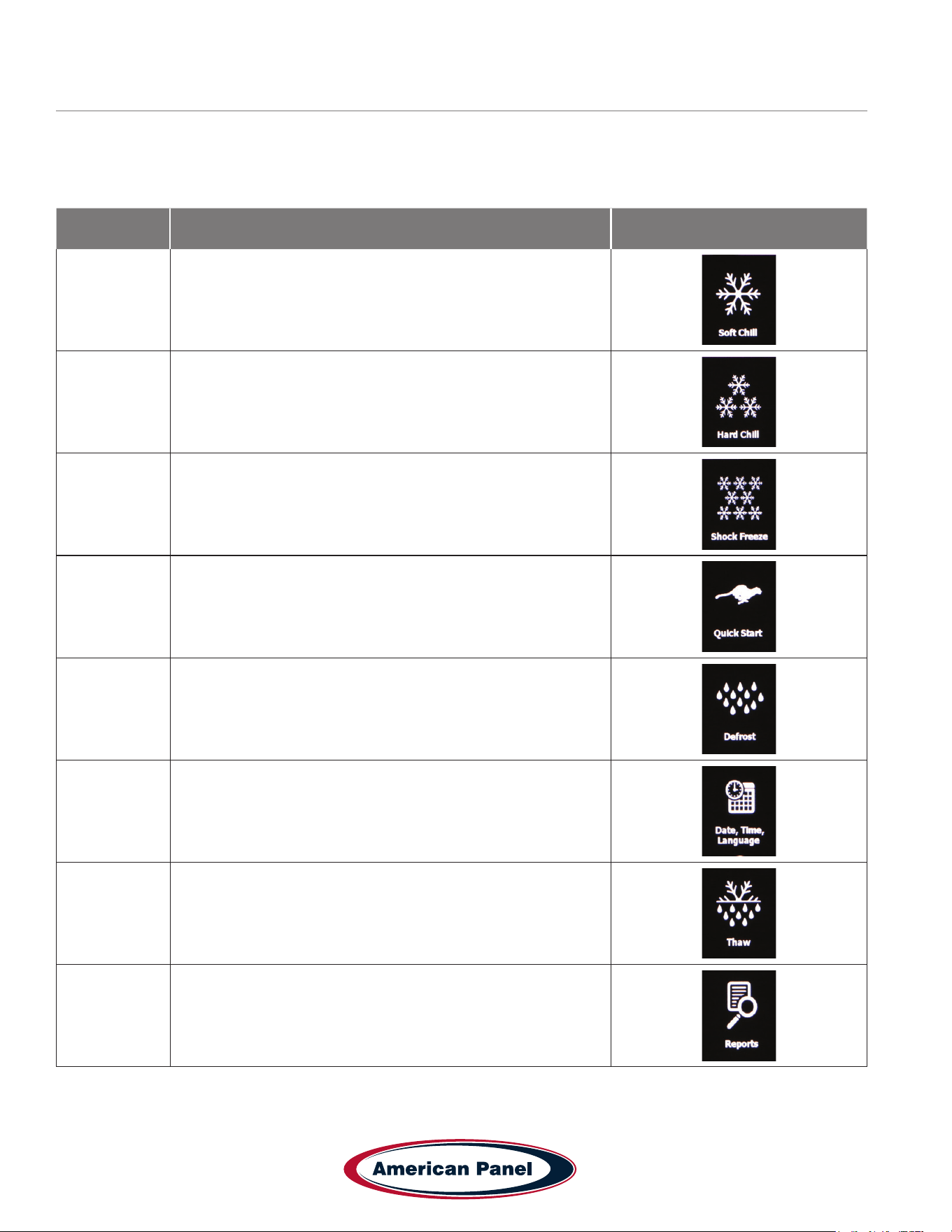
Setting Description Icon
Soft Chill
Temperature and timers settings for the Soft Chill cycle for
each mode: Auto, Manual & A La Carte
Hard Chill
Temperature and timers settings for the Hard Chill cycle for
each mode: Auto, Manual & A La Carte
Shock Freeze
Temperature and timers settings for the Shock Freeze cycle
for each mode: Auto, Manual & A La Carte
Quick Start
Customize the cycle, mode and product name used in the
Quick Start button
Defrost
Settings for: Length of Defrost, Auto Defrost, Auto Defrost
Time, Cabinet Max Temp, Length of Auto Defrost
Date, Time,
Language
Sets the time, date and language (English, French or
Spanish) of the unit.
Thaw
Setts the Air Temp, Food Temp, Fan Settings and Duration for
the Auto and Manual Food Thaw cycles.
Reports
HACCP reports settings: Date Interval, Notication Threshold,
Capacity Disply, Capacity Alert, Clear Reports.
Blast chilling and shock freezing cycles have been designed to deliver optimum chilling/freezing performance for most
food products. If needed, all the cycles and settings can be customized via the settings menu and the screens below.
Settings should only be changed by knowledgeable personnel or at the direction from a service technician.
29
5800 SE 78th St. Ocala, FL 34472
Touchscreen HURRiCHiLL Installation & Operations Manual
P: (800) 327-3015
Customizing the Cycles and Technical Settings - Continued
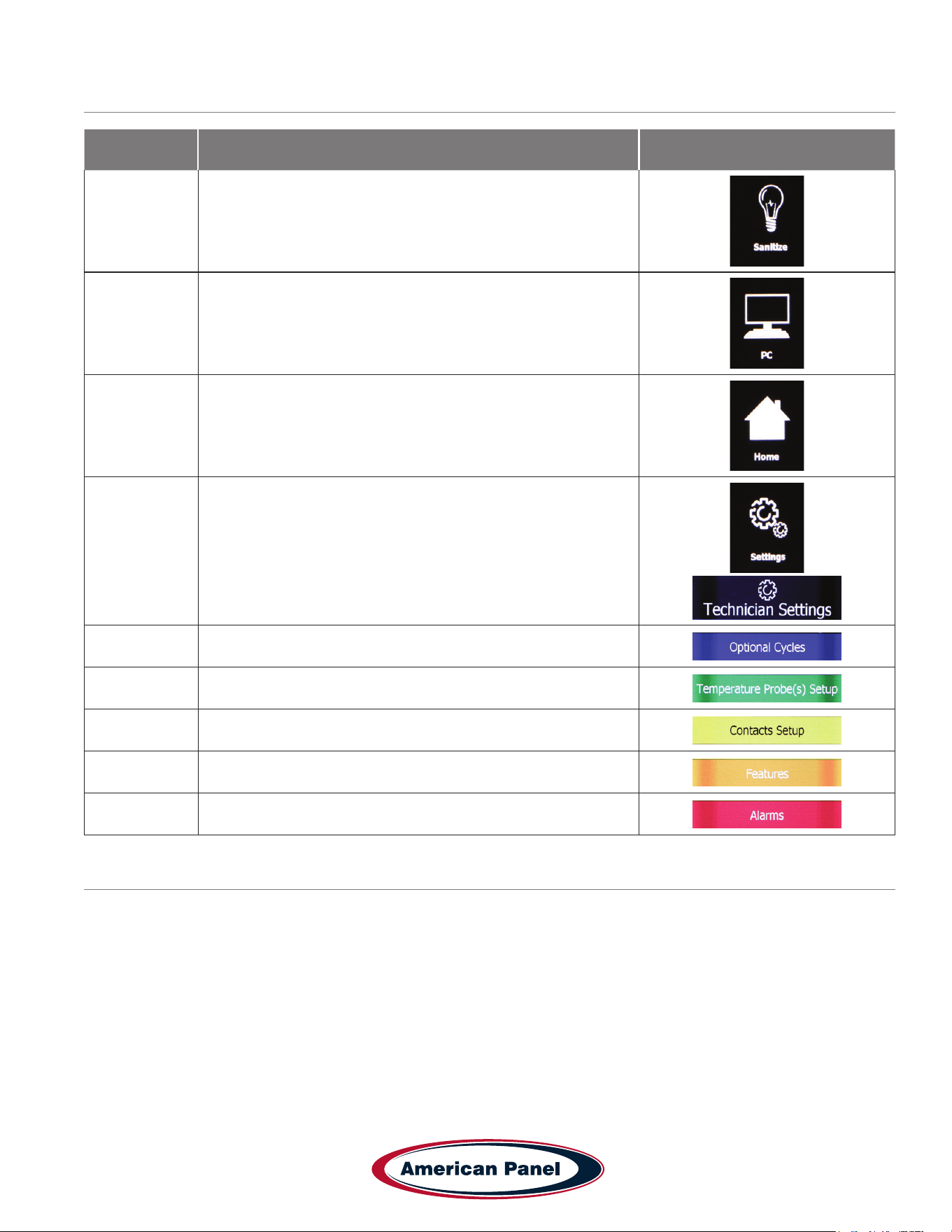
Setting Description Icon
Sanitize
Settings for: Length of Cycle, Auto Sanitation and Auto
Sanitation Time.
PC
Select the type of PC connection you use and see detailed
info on the network settings.
Home Takes you back to the home screen
Settings
Takes you to Technical Settings Screen - Optional Cycles,
Temperature Probe(s) Setup, Contacts Setup, Features,
Alarms, Brightness and Sound settings
Optional Cycles - Choose additional non standard cycles
Probe Settings - Adjust probe temperatures and offsets
Contacts Settings - Settings for contact sensors in the unit.
Features - Technical features to be used by technician
Alarm Settings - Settings for all alarms
Temperature Probes Calibration
1. Determine the temperature offset for the probe you are calibrating. To do so, insert the food probe in an 80% ice
20% water bath and stir for a minute. Record the temperature of the probe as displayed on the touchscreen. The
difference between 32 and the temperature reading is the temperature offset.
For example, temperature probe reading is 38˚F. The temperature offset is -6 (32-38 = -6)
2. Calibrate the probe. To do so go to Settings (7055 Login) > Settings > Temperature Probes Setup. Set the offset
calculated above for the desired temperature probe. Press Done button to go to the home screen.

5800 SE 78th St. Ocala, FL 34472
30
P: (800) 327-3015
Touchscreen HURRiCHiLL Installation & Operations Manual
General Operating Instructions
Panning and Loading
Follow the methods below for faster cooling, freezing and thawing:
• Place the food in shallow pans.
• Do not use food pans deeper than 2 ½” and do not ll the pan with more than 2” of product.
• Separate the food in smaller or thinner portions.
• Do not cover the containers unless danger of overhead contamination.
• Loosely cover the containers if necessary. Allow the cover material (aluminum foil) to touch the surface of the food.
• Arrange the pans for optimum air circulation within the cabinet.
• Know the capacity of the unit. Do not overload the unit.
Probing (for chilling and freezing cycles)
Follow the methods below to ensure correct probing of the product:
• Insert the food probe into the thickest part of the product.
• The tip of the food probe will have to be located at the core of the food.
• Always place the available food probe in the hardest to cool product.
• It is a good practice to restart the cycle every time food is added.
• Clean and sanitize the food probe after each use.
Probing (for optional Thaw cycle)
• Use the provided drill and drill bit to drill a hole into the frozen product.
Maintenance & Cleaning
Daily Maintenance
• Defrost the unit daily or as needed (pg 21).
• Wipe clean the interior and the exterior of the unit using a solution of mild soap and water.
• Wipe clean the door gasket.
• Engage the sanitation cycle (if equipped).
Quarterly Maintenance
The quarterly maintenance should be done by a service technician or by trained maintenance personnel.
• Inspect door hinge for proper operation.
• Inspect door gasket for proper seal.
• Inspect the drain line for proper ow.
• Use vacuum and brush to clean the condenser coil.
• Clean the evaporator coil.
Evaporator Coil Cleaning - see pg. 33
31
5800 SE 78th St. Ocala, FL 34472
Touchscreen HURRiCHiLL Installation & Operations Manual
P: (800) 327-3015
Maintenance & Cleaning - continued
Annual Maintenance Checklist The quarterly maintenance should be done by a service technician or by trained
maintenance personnel.
• Verify unit is properly installed
• Unit is to be rmly situated and level.
• Verify minimum clearances, see chart below.
• Front to back air ow, at the condenser, is to be unobstructed.
• Unit must not be situated near grease, heat, or vapor source.
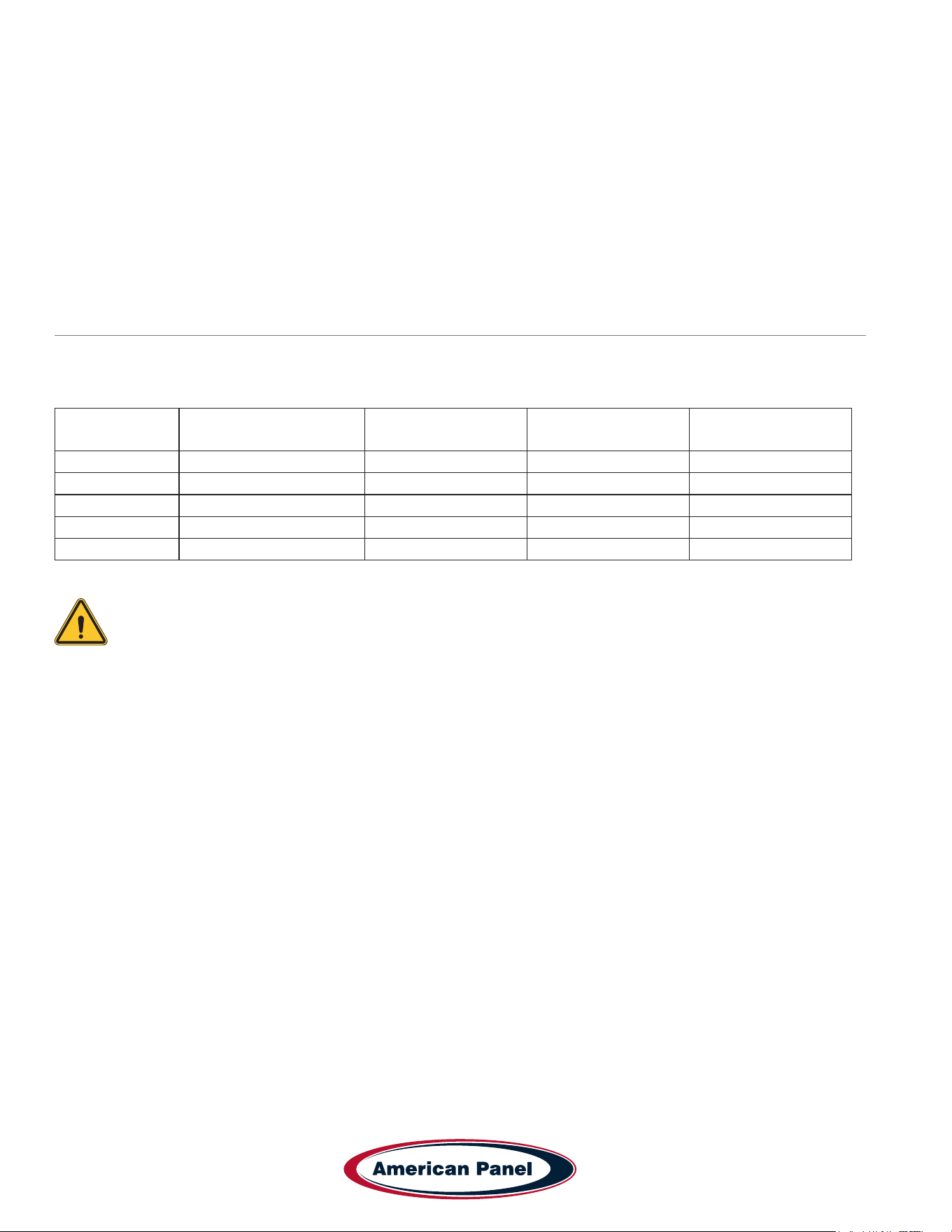
Blast Chiller Model Min. Sides Clearance Min. Rear Clearance Min. Top Clearance
AP7BCF70-2-P 3” 5” 15”
AP7BCF70-2-C-P 3” 5” 15”
AP10BCF100-2-P 3” 5” 15”
AP12BCF150-2-P 3” 5” 15”
AP20BCF200-3-P 3” 8” 15”
• Verify the electrical service to be in accordance with the manufacturer label located on the exterior of the unit.
• Verify proper drain pan installation (clean if necessary) or hard plumbed. Inspect drain lines for integrity and
proper ow.
• Check door hinges and gasket for proper operation and seal. Use mild soapy warm water to clean the door
gasket. Adjust sweep gasket if needed.
• Inspect integrity of the unit, exterior and interior
• Verify evaporator fans are rmly mounted, balanced, free-turning and properly aligned.
• Disconnect unit from the main power and clean the evaporator coil, see the evaporator coil cleaning procedure at
the end of this checklist.
• Wipe down cabinet interior with soapy water and rinse. Do not use any abrasive or corrosive materials!
• Inspect and clean the condenser coil
• Disconnect the unit from power and remove the front and back air inlet/outlet panels. With great care given to
electrical connections and moving parts, inspect the integrity of the condensing unit.
• Lightly brush clean/vacuum any lint and/or dust in cavity with special attention given to the condenser. Do not
use any abrasive or corrosive materials.
• Re-install the front and back air inlet/outlet panels.
• Connect the unit to power supply.
5800 SE 78th St. Ocala, FL 34472
32
P: (800) 327-3015
Touchscreen HURRiCHiLL Installation & Operations Manual
• Use an 80/20 ice/water bath to check the accuracy of the probe. To do so, close the door of the unit with the probe
hanging on the outside of the cabinet and start a manual hard cycle. Use the probe to continually stir the ice-water
bath and observe the readings for approximately 3 minutes. The temperature of the ice-water mixture should be
33 to 34˚F. Adjust as necessary, see Temperature Probe Calibration pg. 29.
• Verify the accuracy of the air probe against a calibrated thermocouple or against an accurate food probe. Adjust
as necessary, see Temperature Probe Calibration pg. 29..
Note: American Panel Corporation blast chillers are equipped with a short cycle protection. If the
unit is stopped during a chilling cycle more than once, the compressor will not start for the following
3 minutes.
• Operate the unit in the hard chill / manual mode, for approximately 20 minutes, to verify temperature pull down.
• Verify the functionality of the evaporator fans. The direction of the air ow for the evaporator should be from the
front of the unit towards the back of the unit.
• Verify the functionality of the condenser fans. Air direction should be from the front of the unit towards the back.
• Inspect sight glass to ensure it is clear and dry
• Check oil level in compressor base to a minimum if 1/2 full on indicator.
• Engage, operate, and verify effectiveness of manual defrost cycle.
• Verify ozone generator (if so equipped) is functional. 10 minutes after engaging the sanitation cycle there will
be a strong ozone smell inside the cabinet indicating that the ozone generator if functional. the UV lamp inside
the ozone generator must be replaced annually. See section “ Replace Ozone Generator Lamp” for replacement
instructions. Contact the American Panel parts department to order replacement lamps.
• Verify Wi-Fi connection (if equipped) is functional.
• Turn unit off, wipe down the exterior with mild soap and water.
• Inform the customer and the factory of any functional and performance issues found following the completion of
the above checks.
• Complete inspection paperwork and verify consumer has all necessary operation manuals, menus, and
instructions. Contact factory with any questions. Monday-Friday 8am to 5pm EST. 1-800-327-3015 or through the
website at www.americanpanel.com.
The above maintenance procedure should be done twice a year and is not a substitute for an
efcient local maintenance schedule such as daily and quarterly maintenance schedule.
Maintenance & Cleaning - continued
33
5800 SE 78th St. Ocala, FL 34472
Touchscreen HURRiCHiLL Installation & Operations Manual
P: (800) 327-3015
Evaporator Coil Cleaning
The following cleaning procedure is recommended as part of routine maintenance activity for all American Panel
Corporation blast chillers.
IMPORTANT: Do not use any sharp or abrasive tools to clean the evaporator coil!
Before cleaning the evaporator coil run the defrost cycle to make sure the coil is completely free of ice.
When cleaning the evaporator coil particular attention must be paid to the kind of cleansing agent used. The following
products MUST NEVER BE USED:
• Ammonia or detergents which contain ammonia (ammoniac solutions)
• Bleach or products containing bleach (chlorinated liquids)
• Acid detergents such as anti-lime scale, various anti-incrustations, muriatic acid, sulfuric, hydrochloric and acetic
acid liquids, etc. (highly acidic liquids)
• Acetone, trichloro-ethylene (organic solvents)
• Caustic soda and other highly alkaline substances (high basicity liquids)
All the above substances can damage the protective coating and/or corrode the metal components and seriously
damage the coil.
WARNING: Disconnect and lock the main power switch prior to cleaning the unit.
Monthly
• Open the evaporator door by removing the screws that secure the door to the vertical frame and swing
the door open.
• Use a vacuum cleaner or a soft non-metallic bristle to remove the surface loaded bers and dirt. Apply the tool in
the direction of the ns.
• Rinse the coil nned area and the return bends with plenty of clean warm water. To avoid damaging the ns and
the coating, it is important that the water temperature is below 130oF and the water pressure is below 100 PSI.
• Close and secure the evaporator door.
Quarterly
• Open the evaporator door by removing the screws that secure the door to the vertical frame and swing
the door open.
• Use a vacuum cleaner or a soft non-metallic bristle brush to remove the surface loaded bers and dirt. Apply the
tool in the direction of the ns.
• Spray the coil nned area and the return bends with a generous amount of the recommended coil cleaner (see
below) using a pump-up sprayer or conventional spray bottle. Refer to the manufacturer’s directions on the
container for proper mixing ratio.
• After cleaning the coil use the approved chloride remover (see below) to remove soluble salts and revitalize the
unit. Use a pump-up sprayer or a conventional spray bottle to soak the nned area and the return bends. Refer
to the manufacturer’s directions on the container.
• Rinse the coil nned area and the return bends with plenty of clean warm water. To avoid damaging the ns and
the coating, it is important that the water temperature is below 130oF and the water pressure is below 100 PSI.
• Close and secure the evaporator door.
Recommended Coil Cleaner
Enviro-Coil Concentrate
Hydro-Balance Corporation
Tel. (972) 394-9422
Recommended Chloride Remover
CHLOR*RID DTS
CHLOR*RID International, Inc.
Tel. (800) 422-3217
5800 SE 78th St. Ocala, FL 34472
34
P: (800) 327-3015
Touchscreen HURRiCHiLL Installation & Operations Manual
Replace Optional Sanitizing Ozone Generator Lamp
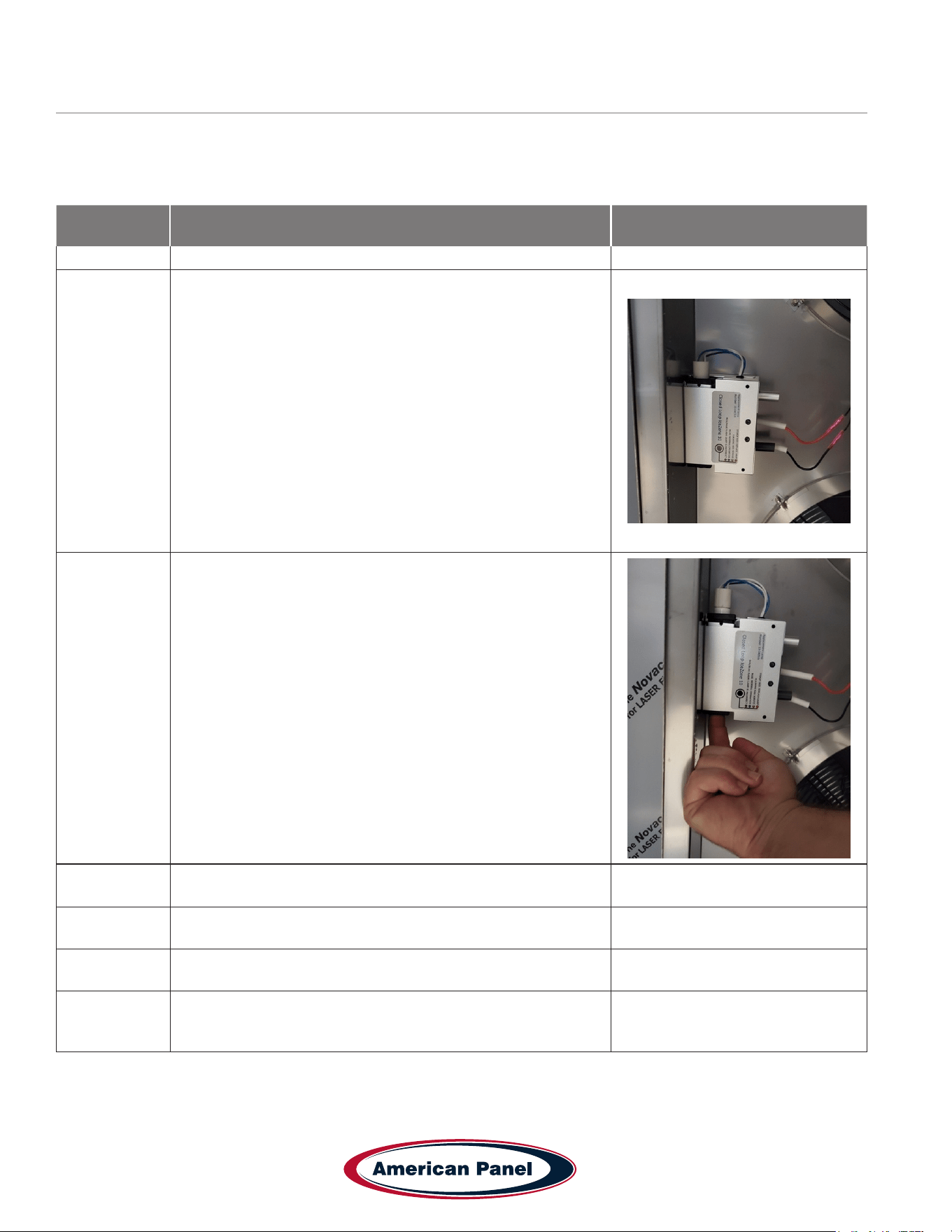
The UV lamp inside the ozone generator has a service life of one year. Contact the parts department at American
Panel Corporation to order replacement lamps. To replace the lamp follow the steps below.
Step Description Action
1 Disconnect the unit from the main electrical power
2
Open the evaporator door. The evaporator door is the sheet
metal that houses the evaporator fans. To open it remove the
screws located on the right-hand side of the evaporator door,
opposite to the hinges. The ozone generator is mounted on
the inside of the evaporator door
3
Remove the old lamp by gently pushing the lamp from the
bottom side until enough of it is to grab.
4
Extract the lamp from the top, pull to disconnect the wire
harness, and replace the lamp
5 Close and secure the evaporator door.
6 Reconnect the main electrical power to the unit.
7
Test the Sanitation cycle. To do so engage the sanitation cycle
and let it run for 5 to 10 minutes. There will be a strong ozone
smell inside the cabinet

35
5800 SE 78th St. Ocala, FL 34472
Touchscreen HURRiCHiLL Installation & Operations Manual
P: (800) 327-3015
This manual is updated as new information and models are released. Visit our website for the latest manual.
990260_APC_HC-TS_OEM
08/25
5800 SE 78th St. Ocala, FL 34472 • 352.245.7055 • [email protected] • www.americanpanel.com
Versatile, Dependable Walk-Ins & Blast Chillers
American panel is your trusted manufacturer for all your cold
storage, blast chilling and shock freezing needs. Building on a
60-year family owned and operated heritage, American panel
provides versatile, dependable custom crafted walk-in coolers,
freezers, combination cold rooms and blast chillers.
American Panel is proud to offer the largest line of blast chillers and shock freezers on the
market. 37 different freestanding models and an innite number of integral congurations.
HURRiCHiLL offers the easiest to use controls in the industry, blast chilling is complex
but controlling it doesn’t have to be. American Panel is the go-to source for all your blast
chilling/shock freezing needs.
Find out more at www.americanpanel.com