Instruction manual
GB
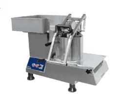
Vegetable
preparation
machine
10/2007
US
TR260
N°29458 D
1.
1
F
B
2.
1
TR260 01-01/2001
T
R260
02- 04/2006
TR260 04-
H
I
J
3.
1
R260
03-04/2006
10
03/2007
TR260 FR 03 07
TR260 FR 05 2003
3.
6
3.6b 3.6c
TR250 24-6/95
3.
7
TR250 25-6/95
TR250 26-6/95
TR250 27-6/95
3.
7a
3.
7b
4.
2a
4.2
4.3
TR250 29-6/95
4.
2b
4.
2c
TR250 28-6/95
TR250 30-6/95
TR250 20-6/95
A
B
A
A
3
.
5c
3
.
5d
3
.
5e
TR260-07-01/2001
TR260 05-01/2001
3
.
5c
TR260 FR 05 2003
F
E
6.3
TR260 FR 03 07
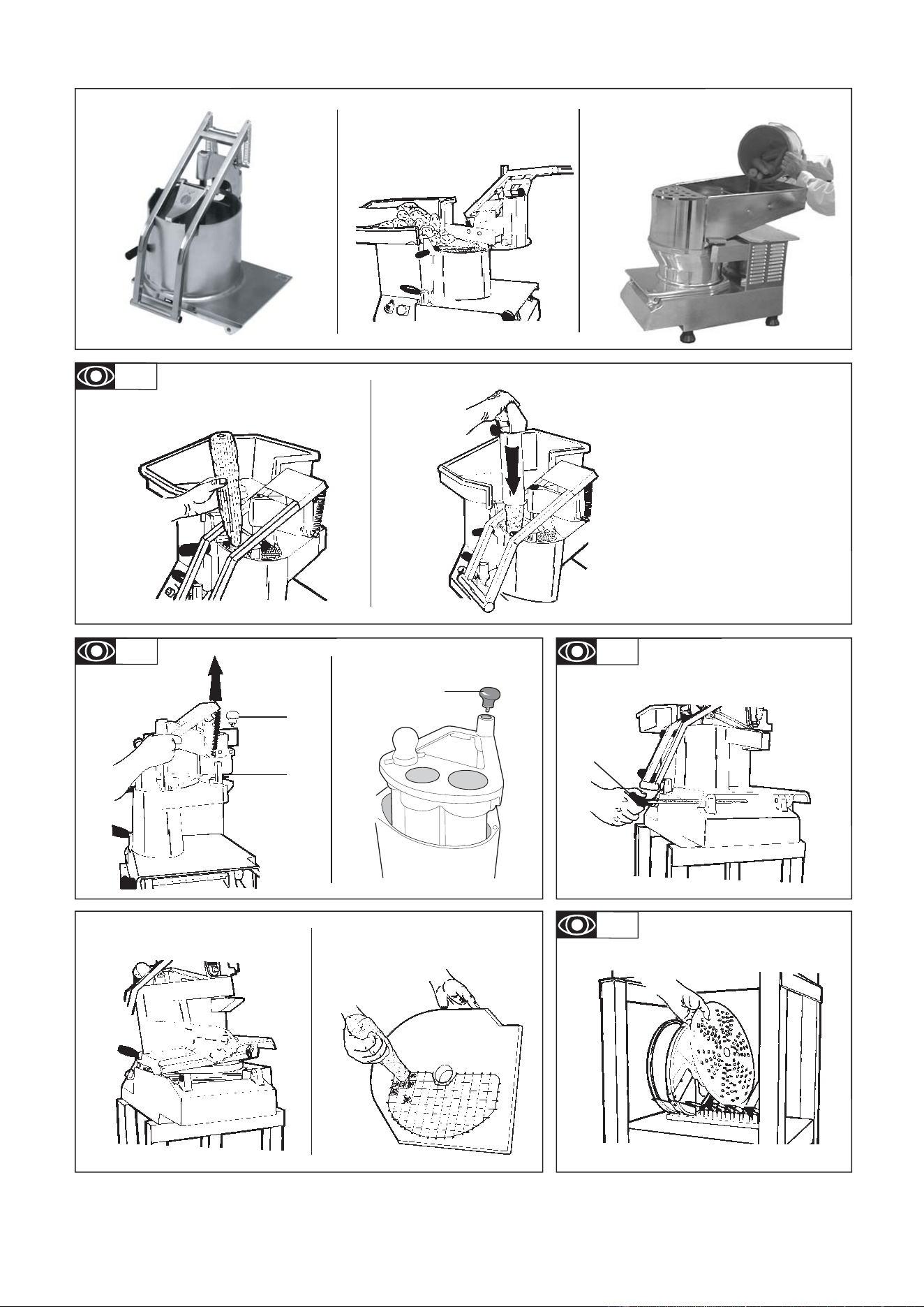
Refer to the numbered drawings
which correspond to the paragraph numbers in the instructions
Introduction 1
Installation 1
Use and safety 3
Cleaning, hygiene and storage 6
Fault fi nding 6
Maintenance 7
Conformity with regulations 8
GB
1
TR260 GB 10 07
1.1
2.1
Contents
Introduction
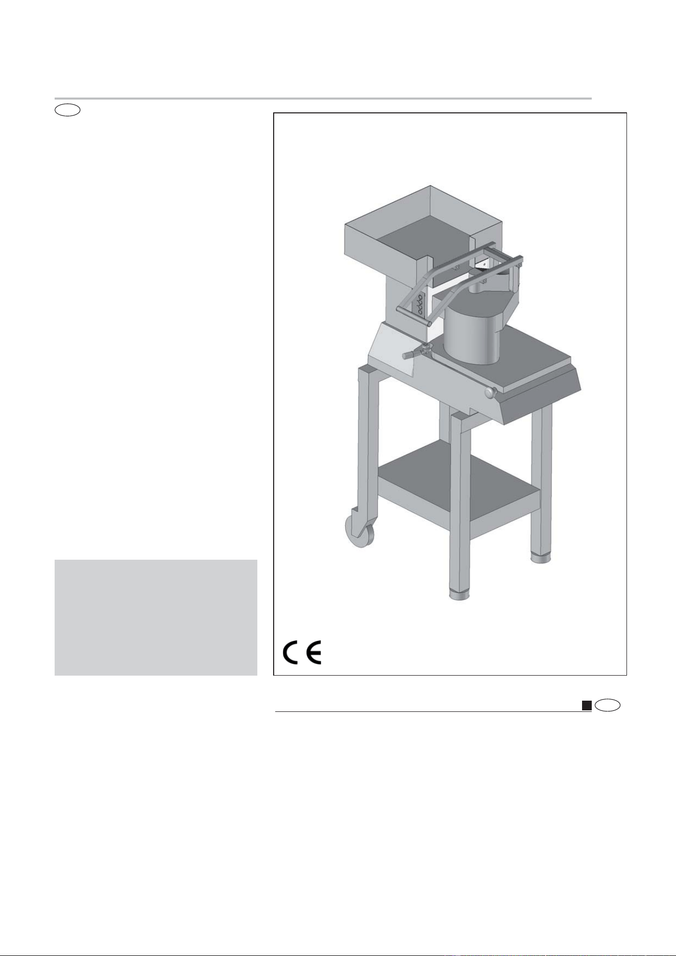
1.1 DESCRIPTION
•
This multi-purpose vegetable cutter can be used to slice, slice
thinly, shred, grate and cut into cubes various food products
(preparation of crudités, vegetables, fruits, cheese, etc.)
With its varied cutting equipment which provides a high hourly
throughput, it is the professional vegetable cutter for community
kitchens and small industrial kitchens.
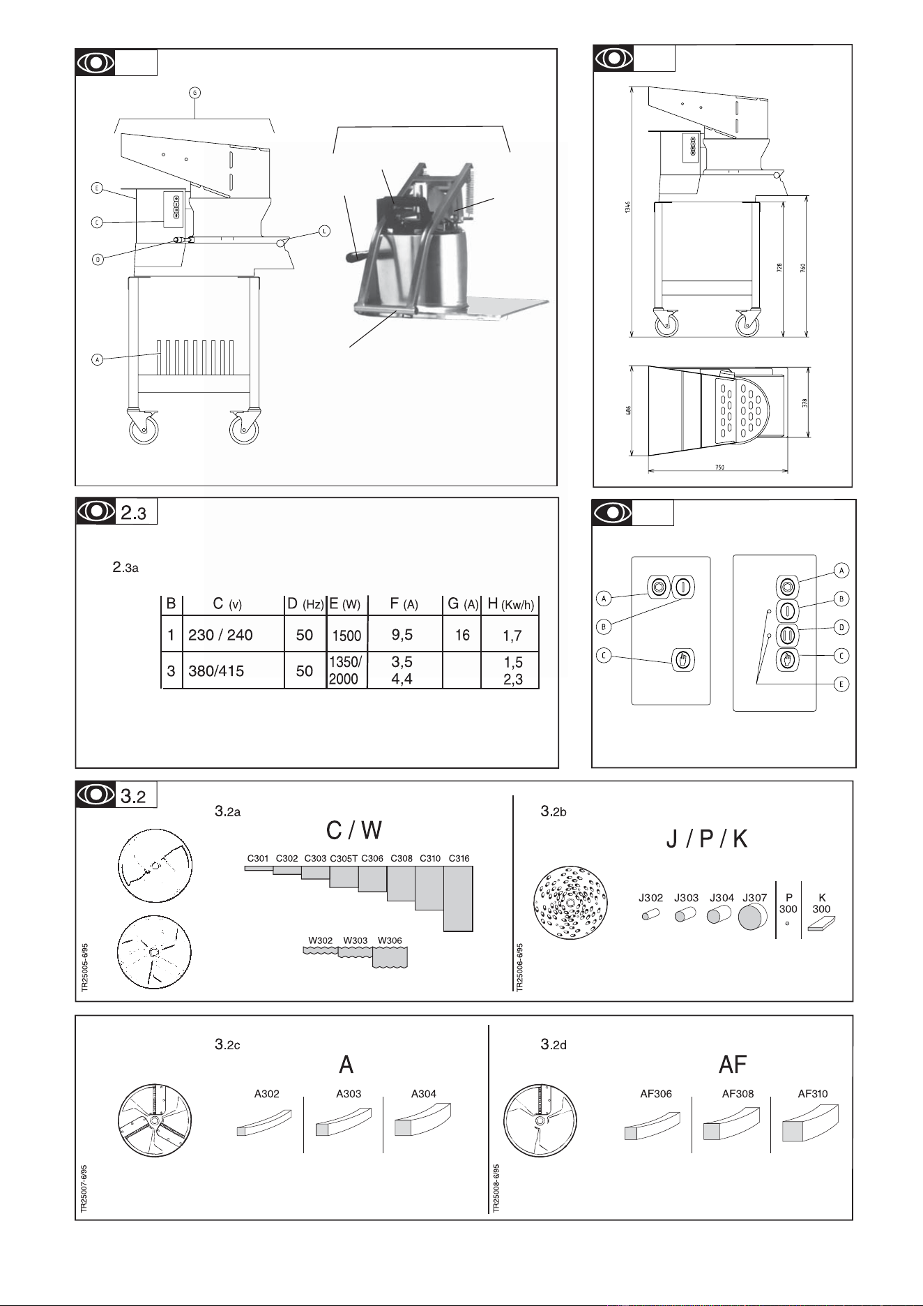
D Lid locking
E Motor protection casing
F Hopper raising handle
G Automatic hopper
H Feed stick
I Small hopper
J Lever-operated hopper
L Lid hinge pin
A Storage rack
B Press lever
C Electric controls
Installation
2.1 OVERALL DIMENSIONS - WEIGHT (for information only)
•
Dimensions of the machine with auto. hopper
- without table: 750 x 490 x 680
- with table: 750 x 490 x 1345
•
Dimensions of the machine with standard hopper
- without table: 860 x 535 x 615
- with table: 860 x 535 x 1280
•
Handling - Transport
- When packed the machine is meant to be lifted using a forklift
truck or a pallet transporter.
- Where the machine is manually handled on its own, two persons
will be required.
•
Packaged dimensions L x w x h (mm):
- TR260 motor unit: 800 x 520 x 580
- Net weight: 49 kg - Packaged weight: 58 kg
- Auto. hopper: 800 x 520 x 580
- Net weight: 15 kg - packaged weight: 23 kg
- Standard hopper + container: 560 x 490 x 610
- Net weight: 18 kg - Packaged weight: 22 kg
- Cabbage hopper: 560 x 490 x 610
- Net weight: 15 kg - Packaged weight: 19 kg
•
Table packaged dimensions: 750 x 500 x 200
10/2007
Introduction
The User Manual contains useful information for the user on
how to work correctly and in complete safety, and is designed
to make it easier to use the machine (called «machine» or
«appliance» below).
What follows is in no case intended to be a long list of warnings
and constraints, but rather a series of instructions meant to
improve the service provided by the machine in every respect,
and particularly to avoid a series of injuries or damage to equi-
pment that might result from inappropriate procedures for use
and management.
It is essential that all the people responsible for transporting,
installing, commissioning, using, maintaining, repairing or dismant-
ling the machine should consult this manual and read it carefully
before proceeding with the various operations, in order to avoid
any incorrect or inappropriate handling that might be result in
damage to the machine or put people’s safety at risk.
It is just as important that the Manual should always be available
to the operator and it should be kept carefully where the machine
is used ready for easy and immediate consultation in case of any
doubt, or in any case, whenever the need arises.
If after reading the Manual, there are still any doubts concerning
how to use the machine, please do not hesitate to contact the
Manufacturer or approved After Sales Service provider, who
is constantly available to ensure quick and careful service for
improved machine operation and optimum effi ciency.
Note that the safety, hygiene and environmental protection stan-
dards currently applicable in the country where the machine is
installed must always be applied during all phases of machine
operation. Consequently it is the user’s responsibility to ensure
that the machine is operated and used solely under the optimum
safety conditions laid down for people, animals and property.
2.2 LOCATION AND ORGANISATION
! Always place the machine on a strong, fl at, stable
support
2.2
•
It is recommended that the vegetable cutter is fi xed onto the
moveable table (available as an option) which is more practical
and which accepts the standard, large dimension reception
containers; otherwise stand it on a table of a height of between
600 and a maximum of 750 mm.
•
To chock and level the table:
- Unscrew the fi xing screw on the 2 pads (10 mm tube spanner),
- adjust the pad, then lock in position,
- check the machine is stable.
•
If the moveable table requires setting in place:
- Counter drill the holes for the 2 pads (ø 5 x 40 screw and plugs
not supplied).
2.3 ELECTRICAL CONNECTION
Connection to the electrical power supply must be done according to proper professional practice by a qualifi ed and authorised
person (see current standards and legislation in the country of installation).
If an adapter is used on the socket, a check must be made that the electrical characteristics of this adapter are not lower than
those of the machine.
Do not use multiple plugs
The AC power supply to the machine must comply with the following conditions;
- Maximum voltage variation: ±5%
- Maximum frequency variation: ±1% on a continuous basis, ± 2% over short periods
ATTENTION: the electrical installation must comply (for design, creation and maintenance) with the legal and standard
requirements in the country where used.
- Before connecting the machine to the electrical power supply, check that the voltage of the electrical system is the same as
that marked on the rating plate and the label on the power cable.
- The machine’s electrical power supply must be protected against voltage surges (short-circuits and excess voltages) by
using fuses or thermal relays of the appropriate gauge relative to the place of installation and machine specifi cations - see the
specifi cations shown in column G of fi gure 2.3a
ATTENTION: Concerning protection against indirect contact (depending on the type of power supply provided and
connection of the exposed conductive parts to the equipotential protection circuit), refer to point 6.3.3 of EN 60204-1 (IEC
60204-1) with the use of protection devices for automatic shut-off of power in the event of an insulation fault with a TN or
TT system, or, for the IT system, with the use of a permanent insulation or differentials controller for automatic shut-off.
The requirements of IEC 60364-4-41, 413.1 must apply for this protection.
For example: in a TT system, a differential circuit breaker must be installed upline of the power supply, with a suitable
power cut-off (e.g.: 30 mA) on the earthing installation for the place where it is planned to install the machine.
ATTENTION: Failure to comply with these instructions means the customer runs the risk of machine failure and/or acci-
dents due to direct or indirect contacts.
ATTENTION !!
2.3a
•
Check that the mains electrical supply voltage is the same as
the value shown on the specifi cations plate and the label on the
power cable.
•
The installation should be protected by an RCD and a fuse of
the rating shown in column G of the specifi cations.
•
Motor specifi cations:
B Number of phases (1 single phase or 3 three phase)
C Nominal voltage in volts (value, range or commutation)
D Frequency (Hertz)
E Nominal rating (Watt)
F Nominal intensity (Amperes)
G Rating of the electric line protective fuse (Amperes)
H Indicative electrical consumption (K Watt/hour)
•
The Vegetable-cutter power supply is either single-phase or
three-phase depending on the model. The three-phase model
has two speeds: 325 and 650 rpm.
The single phase model has only one speed: 325 rpm.
•
For vegetable-cutters with a single phase power supply, an
easily accessible, standardised sealed 2 pole + Earth wall-moun-
ted socket rated at 10-16A will be required and a corresponding
watertight plug to be fi tted on the power supply cable
•
For vegetable cutters with a 3-phase power supply, provide
an easily accessible, standard watertight 10A wall socket with 3
poles + earth, and a corresponding watertight plug to be fi tted
on the power supply cable.
- Check the direction in which the ejector is turning by means
of the chute. The ejector should be turning anti-clockwise
.
• If it is turning in the opposite direction, change over the two
phase wires in the plug.
To PAT test the Electrolux Range of Food Preparation Equipment,
the PCB board needs to be disconnected before any test is done.
This is due to the fact that the boards are fi tted with a grounding
diode that can give incorrect result during such a test. Also on
a standard appliance a fl ash test of 25 amps and up to 3000v is
used but, as you would expect, to use this on equipment, which
has a printed circuit, board would be quite destructive to that
board. We would recommend the use of a PAT tester approved
for computer systems which use a lower rate of amps.
The appliance is perfectly safe and is CE certifi cated. There are
two ways to get overcome this problem.
· Disconnect the board as instructed and test using test for
PC’s,
· Or install the mixer on a fused spur (no plug) as this takes it
away from being a portable appliance and the PAT test is then
not needed.
TR260 GB 10 07 2
Machine storage: -25°C to +50°C
Ambient temperature during operation: +4°C to +40°C
Clean the machine properly prior to its fi rst use
This machine is for professional use and must be used by staff trained to use, clean and maintain it, in terms or reliability and
safety.
Use the machine in adequately lit premises (See applicable technical standard for the country of use. In Europe, refer to standard
EN 12464-1)
When handling the machine, always check that the parts taken hold of are not mobile elements: risk of dropping and injury to
the lower limbs.
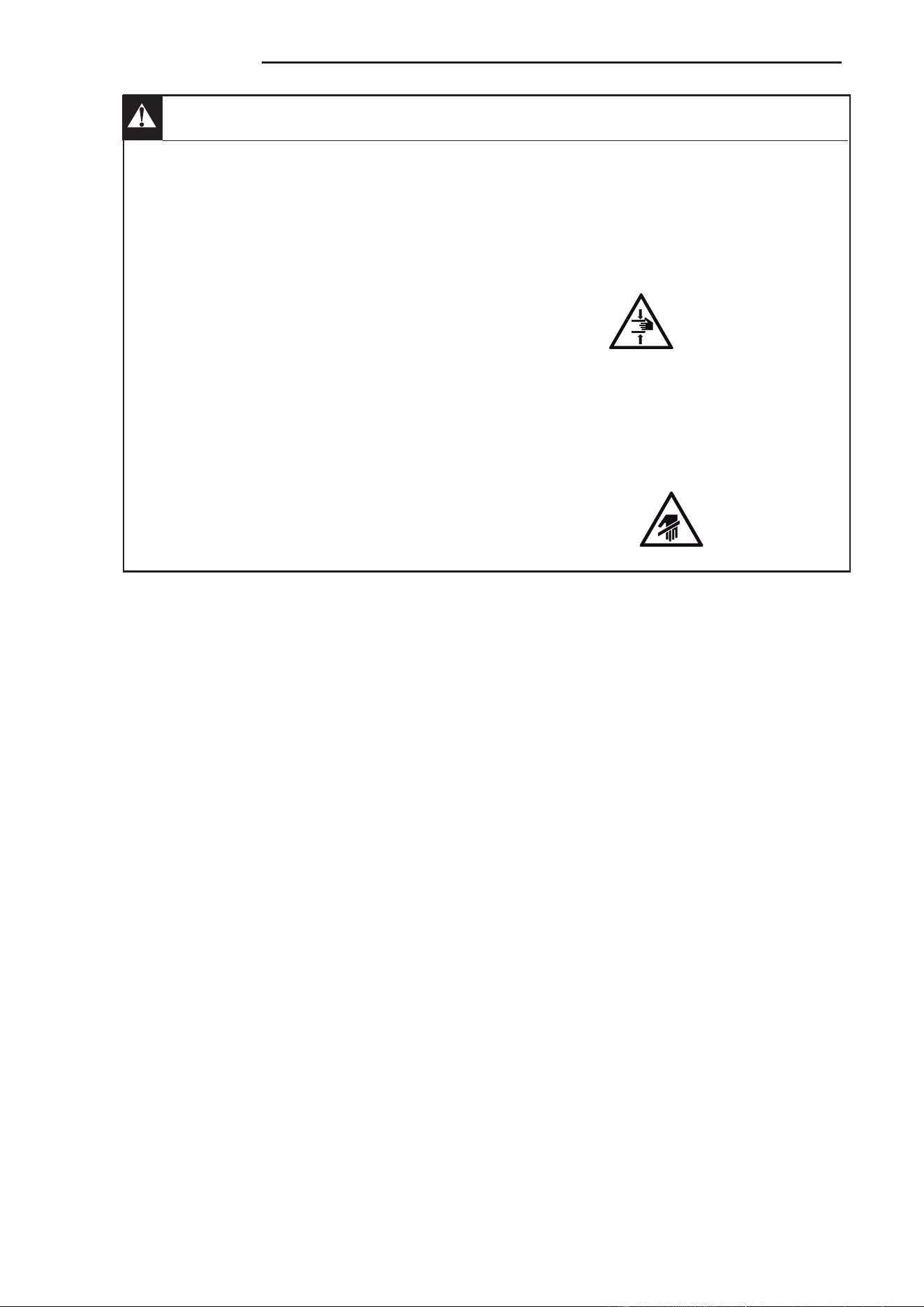
Uncontrolled closure of the lid or ram press involves a risk of crushing the fi ngers.
Never put a hand in the ejection area while the machine is in operation; risk of injury. It is strictly forbidden to put the safety
systems out of action or modify them: Risk of permanent injury!!!!
Check that the safety devices operate correctly each time before using (see paragraph on «safety system adjustments»).
Never put a hand, a hard or frozen object in the appliance
For health and safety reasons, always use a washable or disposable strong head covering that covers the hair completely.
ATTENTION: All operations, whether using, cleaning or maintenance, present risks of cuts; never force and always keep
hands a reasonable distance from cutting edges.
Always use appropriate protective equipment when carrying out these operations.
The machine is not designed for use in explosive atmospheres.
ATTENTION !!
Use and safety
3.1 THE USER’S SAFETY IS ENSURED BY:
•
With the automatic hopper:
The braked stoppage of the motor on opening the hopper and
the impossibility of starting when it is not in place
By the geometric design and the bars on the stainless steel loader
which prevents inadvertent access to the cutting unit.
•
With the lever-operated hopper:
- The braked stoppage of the motor on opening the lever
- The impossibility of starting the motor when the lever-press or the
long-vegetable hopper is not in place or on opening the lid when
it is fi tted with the lever-press or the long-vegetable hopper.
- The dimensions of the small long-vegetable hopper and the
large hopper.
- The absence of risk from accessing the evacuation spout
linked to the design of the ejector and the discs.
- Familiarity with and observance by the user of these instructions
for using, cleaning and maintaining the appliance.
A Stop button
B Speed 1 start button
C Pulse operation button
D Speed 2 start button
E Speed indication lamps
The slicer can be started if the hopper is lowered.
a) Continuous operation:
- start by pressing on B: speed 1
- start by pressing on D: speed 2, indicated by indicator lamp
E for the 2 speed model.
b) Pulse operation:
- start by pressing on C:
c) Stop:
- always use button A at the end of an operation.
RESIDUAL RISKS
The machine presents the following residual risks;
• The upper cover of the machine may result in the fi ngers being
crushed if it is closed without being controlled properly.
• If a hand is placed in the area where the products are dis-
charged, it may be crushed or trapped by the rotating parts of
the machine.
3 TR260 GB 10 07
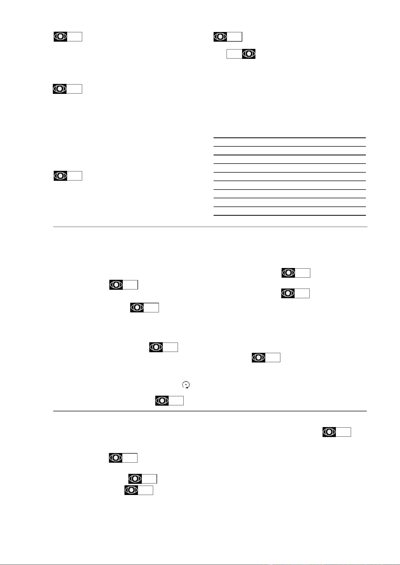
3.2 CHOICE OF CUTTERS:
•
slicing discs C: for straight cuts from 1 to 16 mm.
•
slicing discs W: crinkle cut from 2 to 6 mm for:
- Vegetables: potatoes, carrots, aubergines, beetroot, celery,
mushrooms, courgettes, chicory, fennel, leeks, sweet peppers,
radishes, etc.
- Fruits: bananas, lemons, oranges, apples, rhubarb, etc.
•
grating discs J-P-K:
J302: fi ne J303: medium
J304: large J307: extra large
- Vegetables: carrots, «straw» potatoes, grated celery, red
cabbages, beetroots, horseradishes, rösti.
- Cheeses: gruyère, mozzarella.
- Other: walnuts, almonds, bread crumbs, chocolate, etc.
•
P : for Parmesan, bread crumbs, almonds, horseradishes,
chocolate.
•
K: special grating of raw potatoes (Knödeln)
•
A shredding discs: for cutting into chips of 2 to 4 mm
A302:thin 2 x 2 mm
A303:medium 3 x 3 mm
lA304:arge 4 x 4 mm for matchstick potatoes
3.2a
3.2b
3.2c
3.2d
3.2e
}
straw potatoes, celery, carrots
• shredding discs AF: for cutting of larger chips of 6 to 10
mm.
-dicing grids AM: for square section cuts of 8 to 25 mm when
used with a C disc.
- Cubes: macedoines of vegetables or fruits, jardinières, mines-
trones, sautéed or braised potatoes, stews.
•
Indicative outputs (kg/h):
- These outputs depend upon the layout of the work station
(speed of changeover, etc.) and the type of products that are
being processed.
Crisps C301 300/350
Potato scallops C303 500/550
Grated carrots C303 150/200
Cabbages, chopped onions C302/C303 350/450
Cucumbers C303 150/200
Grated carrots J303 300/350
Grated cheese J302 300/330
Straw potatoes A303 400/500
Chips AF308 550/600
Sautéed potatoes C310/AM310 600/650
3.3 USE OF THE CUTTERS
•
The vegetable cutter is supplied with the feed tray loose and
the ejector fi tted to the drive hub.
Note: Before using the cutters, always check the cleanliness of
the cutting chamber, the drive shaft, the ejector, the cutting disc
or grid and the feed tray.
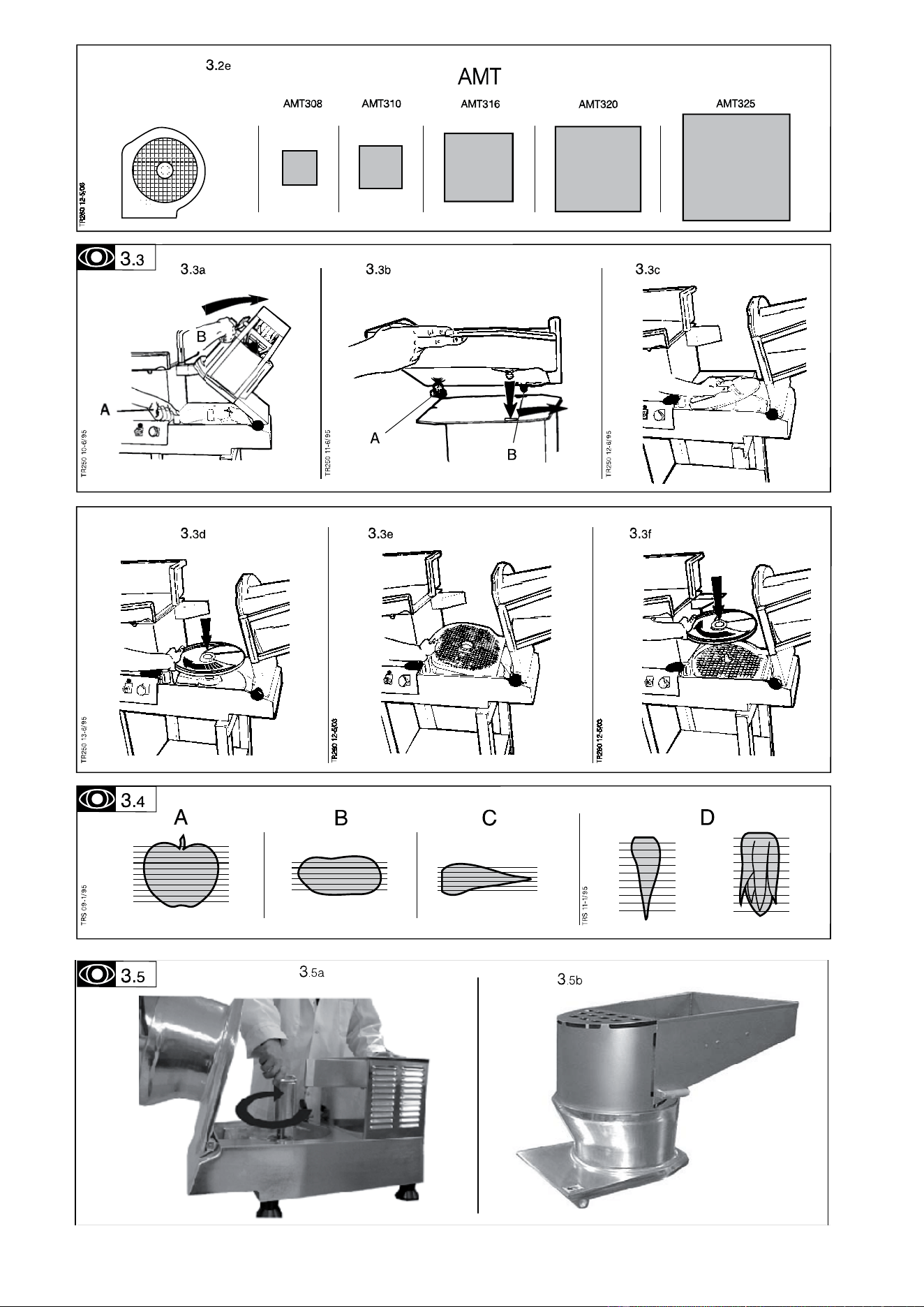
•
Proceed as follows:
- turn the handle A in order to release the cover lock, then lift it
as far as possible using the handle B.
- Put the feed tray in position , fully unscrew
the screw A, introduce the two pins B, in the holes of the disc,
push the tray in as far as possible then retighten the screw
A.
- Remove the ejector
1) For slicing, shredding and grating
•
Fit the ejector onto the hub so that the three pins of the hub slot
into the holes of the ejector. Check that the ejector is correctly
seated (see § 4 - cleaning).
•
Fit the chosen disc ( for slicing C/W, for shredding A/AF, for
grating J/P/K) by turning it in a clockwise direction to line
it up with the bayonet fi tting, so that the disc drops into place.
Continue to turn until the stop is reached.
Note: If the disc is fi tted correctly, it will touch the end of the shaft
and will not be able to be lifted.
Close and lock the cover.
2) For cutting into cubes
•
Fit the ejector (see § 3.3.1).
•
Fit the grid into its housing and check that it is seated cor-
rectly
(seating area is clean, see § 4.1).
Note: The upper face of the grid must be 4 mm below the top
of the machine body.
•
Fit the slicing disc C/W, then close and lock the cover
(see § 3.3.1).
•
If the cover will not lock, check each item of equipment one
by one in order to fi nd out which one is incorrectly fi tted.
3.3a
3.3b
3.3c
3.3a
3.3d
3.3e
3.3f
3.4
3.4
3.5e
3.5d
3.4 CHOICE AND FUNCTIONS OF THE FEED HOPPERS
1) Automatic hopper
- This hopper is used in particular for regularly shaped vege-
tables such as potatoes, carrots, celery, (pre-sliced where
appropriate), tomatoes, etc. Loading is in bulk by loads of
approximately 5 kg.
The work caried out with this hopper is thin slicing, grating,
shredding, dicing and chips.
2) Lever-operated hopper
- Passage for large products (volume of 2.5 L, corresponding
to 1/2 a cabbage).
- Loading is carried out manually by sliding the products from
the feed tray to the hopper.
- Direction for introducing the products for:
A/B Slicing
C/B Shredding – Grating
D Long vegetable
3) Small hopper with removable feed stick
- Passage for long (carrots, cucumbers, courgettes, leeks,
bananas, etc.) and fragile products (tomatoes, kiwis, etc.).
Opening 70 x 60 mm MAXIMUM.
- Manual loading is carried out by inserting the products vertically
into the small hopper one at a time or in handfuls.
TR260 GB 10 07 4
3.5a
3.5 USING THE AUTOMATIC HOPPER
The automatic hopper is always used with the impeller screwed
onto the tool holder shaft.
The vegetable slicer output is increased when there is a
continuous feed. The maximum section of the vegetables or
vegetable quarters which can be accepted by the automatic
hopper is 100 mm.
4) Long vegetable feed hopper (available in option)
- Passage for long, thin vegetables (carrots, cucumbers, cour-
gettes, leeks, bananas, etc.) and fragile products (tomatoes,
kiwis, etc.).
- The hopper has three inlet diameters, 50, 60 and 70 mm, which
means that the products can be supported correctly according
to their size.
- The direction and method of loading is the same as that of the
small hopper (see § 3.4.2).
5) Cabbage hopper
- The special hopper for cabbage can be used for thin slicing
by using the plate fi tted with a stem-removal device.
3.5c
Never insert a hard object in the feed hopper when the machine
is in operation.
3.5d
3.6. USING THE LEVER-OPERATED HOPPER
•
This vegetable cutter will only operate if the cover is closed.
- Leave the feed stick inside the small feed hopper to prevent
the products from coming back out.
- Place the products on the feed tray.
- Maximum capacity is a 10 L bucket.
- Press the start button B.
- Lift up the feed arm with one hand and move clear towards
the right.
- As soon as the feed arm is clear of the feed hopper, the motor
stops immediately (the green light remains lit), thus allowing
the products to be changed in complete safety.
- With your left hand, push the products in the feed tray towards
the inside of the feed hopper, taking care not to exceed the
upper level.
- Bring the feed arm back into its original position.
- When the feed arm is above the feed hopper, the TR 260 will
start up again automatically.
- Using the feed arm, push the products into the hopper until it
reaches its lower stop.
- Raise the feed arm and repeat this sequence of operations.
- When the work has been completed, press STOP button A.
Tips: Adjust the force applied to the feed arm to suit:
- the product being processed (soft product: less force)
- the cutter chosen (a grating disc requires more force than a
slicing disc).
Do not leave the power supply to the machine switched on if
stopped for a long time with the feed arm out of the hopper.
Never insert a hard object in the feed hopper when the machine
is in operation.
3.6c
3.6b
3.7 USE OF THE SMALL FEED HOPPER AND THE FEED STICK
- Leave the feed arm in its lower position and the cover locked.
- Pull the knob A to remove the feed stick.
- Place the products in the feed tray within reach.
- Press the start button B.
- With your left hand, place the products in the hopper one
by one or in handfuls, fi lling the hopper opening as much as
possible.
- Push the products using the feed stick.
Tips:
- Always introduce long products lengthways.
- To avoid angled and irregular cuts, place thin products in
«head fi rst».
- Cut off the ends of the vegetables to avoid blockages.
Never place your hand inside of the small hopper, always use
the feed stick.
3.7a
3.7b
Never insert a hard object in the feed hopper when the machine
is in operation.
3.8 USE OF THE HIGH OUTPUT LONG VEGETABLE FEED HOPPER (AVAILABLE IN OPTION).
•
To fi t the long vegetable feed hopper, proceed as follows:
- Press the STOP button A.
- Place the feed arm in the raised position.
- Unscrew the locking knob A
- Raise the feed arm in order to remove it from the hinge pin
B.
- Fit the long vegetable feed hopper onto the hinge pin B and
lower it down to the bottom of the feed hopper.
- Tighten the knob A to lock the assembly in place.
Note: With the long vegetable feed hopper in position, the machine
can then be started.
- Press the start button B.
- Introduce the products one after the other in the tubes which
match their size.
- Push them in with the feed stick or the following vegetable.
Tips: (see § 3.6)
•
If the products remain blocked in the tubes:
- press the STOP button A.
- unlock and raise the cover (see § 3.3).
- push the products from the inside towards the outside of the
tube.
5 TR260 GB 10 07
Cleaning, hygiene and storage
4.1 IN BETWEEN USE
- Open the cover and remove the cutting equipment (disc, grid,
ejector, see § 3.3) so that it may be washed in hot water.
- Wash the cutting chamber using a clean, damp sponge, paying
special attention to the grid supports, the outlet chute and the
inside of the hoppers.
ATTENTION !!
Before dismantling any part, disconnect the appliance from the power supply.
Before using any cleaning product, be sure to read the instruction and safety instructions accompanying the product and use
appropriate protective equipment.
Do not clean the machine with a pressure cleaner
4.3
4.2C
4.2 AFTER USE
1) for the lever-operated hopper, remove the feed tray (see § 3.3)
and release the press lever from its swivel pin (see § 3.7).
2) for the automatic hopper, remove the press lever and withdraw
the cutting equipment.
3) In all cases, release the lid from the body by pulling pin A and
unlock the lid and raise it.
Tip: Before cleaning grids, push any cubes that are stuck with
a carrot. Do not use metallic objects.
- Clean the removable elements in a dish of water or in a dis-
hwasher using hot water and detergent/degreaser/disinfectant
compatible with the equipment.
- Rinse with clean water and leave to dry.
- Wash the cutting chamber using a damp sponge and a de-
tergent - disinfectant then rinse.
- If necessary, clean the outside of the machine and its table
using a damp sponge and a mild detergent, then rinse using
a damp sponge.
Tips: Do not use abrasive detergents which scratch the surfaces,
or chlorine based products which dull the aluminium.
- Do not clean the plastic parts in a dishwasher
4.3 STORAGE
•
After cleaning, carefully store each item of the cutting equip-
ment in the storage rack, which can hold 6 discs or grids. This
may be fi xed:
- On the shelf of the mobile table.
- On the wall using two brackets (access height of 1.80 m
max.).
Fault fi nding
5.1 THE MACHINE WILL NOT START, CHECK THAT:
•
The machine is plugged in.
•
The electrical power supply to the socket is correct.
•
The cover is closed.
•
The feed arm is in the feed hopper.
•
If the machine stops whilst in the middle of an operation:
- the thermal relay has been tripped. It will reset itself automa-
tically.
- wait for a few minutes before restarting.
- press the START button B and if necessary, reduce the force
applied to the feed arm.
5.2 ABNORMAL NOISES
•
Stop the machine immediately.
•
Check that the disc, grid and ejector are fi tted correctly (the
grid may be rubbing against the grid).
•
Dismantle, clean if necessary and check there are no foreign
bodies and refi t correctly.
•
If the noise continues and the machine lacks power, check
that:
- the triple phase motor is not operating on double phase
- the belt is not worn or needs to be tensioned (see §6.1)
5.3 BLOCKAGE OF A DISC
- Unplug the machine.
- Place one hand fl at on the ejector and prevent it from tur-
ning.
- With your other hand, hold the outside of the disc in the fi ngers
holes and turn sharply anti-clockwise .
- Lift it whilst turning backwards and forwards.
TR260 GB 10 07 6
5.
4 WORK QUALITY
•
Before carrying out any work, stop the machine.
•
If the products have not been cleared properly, check that:
- the ejector is fi tted correctly,
- the products in the receiving bowl are not blocking the outlet,
- there is not an accumulation of products in the cutting cham-
ber,
- there are no foreign bodies or broken cutting elements inside
of the cutting chamber.
•
If the quality of the cut is not satisfactory, check:
- the direction of rotation (anti-clockwise viewed from
above),
- that the correct cutting equipment has been chosen (see
§3.2),
- the condition of the cutting equipment (see § 6.2),
- the choice of the feed hopper (see § 3.4),
- the way that the products are placed in the feed hopper (see §
3.4).
If the problem persists, contact the service department of
your local dealer.
Maintenance
ATTENTION!!
Unplug the machine before carrying out any operation.
Maintenance may only be carried out by a qualifi ed, trained and authorised person.
6.1 MECHANICAL PARTS
•
The vegetable cutter requires a minimum amount of mainte-
nance (the motor and the mechanical part bearings are greased
for life).
•
It is recommended to check the tension and wear of the belt
at least once a year.
In order to check it, proceed as follows:
- Unplug the machine,
- remove the TR 260 from its table (4 screws - 19 mm spanner)
or unscrew the four feet (TR 260 without table) and lie it on its
side,
- remove the central screw and remove the bottom plate.
•
To change or tension the belt:
- Unscrew (by 2 turns max.) the 4 retaining screws of the motor
mounting (13 mm spanner).
- Lightly unscrew the tensioning screw on the left hand side and
the locknut (10 mm fl at spanner) until the belt is loose on the
pulleys.
- Push the driven pulley hard with your right hand in order to
give the belt its initial tension.
- At the same time, tighten the tensioning screw with your left
hand (no tool required).
- Measure the distance between centres of the two pulleys.
- Tighten the tensioning screw by 4 turns using a spanner, which
corresponds to an increase of around 3 mm of the distance
between centres.
- Tighten the tensioning screw lock nut and the four motor
mounting retaining screws.
- Remove any belt dust from the inside of the housing.
- Check the condition of the electrical connections.
- Refi t the bottom plate, the central screw, the four feet or the
four table attachment screws.
•
Periodically:
- Grease the cutting equipment drive shaft with liquid paraffi n.
6.2 MAINTENANCE OF THE CUTTING EQUIPMENT
•
C slicing discs: sharpening of the blades
- Remove the attachment screws.
- Sharpen with a grindstone, keeping the blade at the same
angle.
•
AF slicing discs:
- The blades are sharpened in the same way as those of the C
slicing discs (see above).
- The blade blocks are interchangeable.
•
AM grids:
The blades may not be changed as they are moulded.
- If necessary, sharpen using a small fi le to repair any damage
caused to the blades by a shock or impact.
•
J/P/K graters:
The graters cannot be re-sharpened.
- In the case of major wear of the grater teeth, change the
cutter.
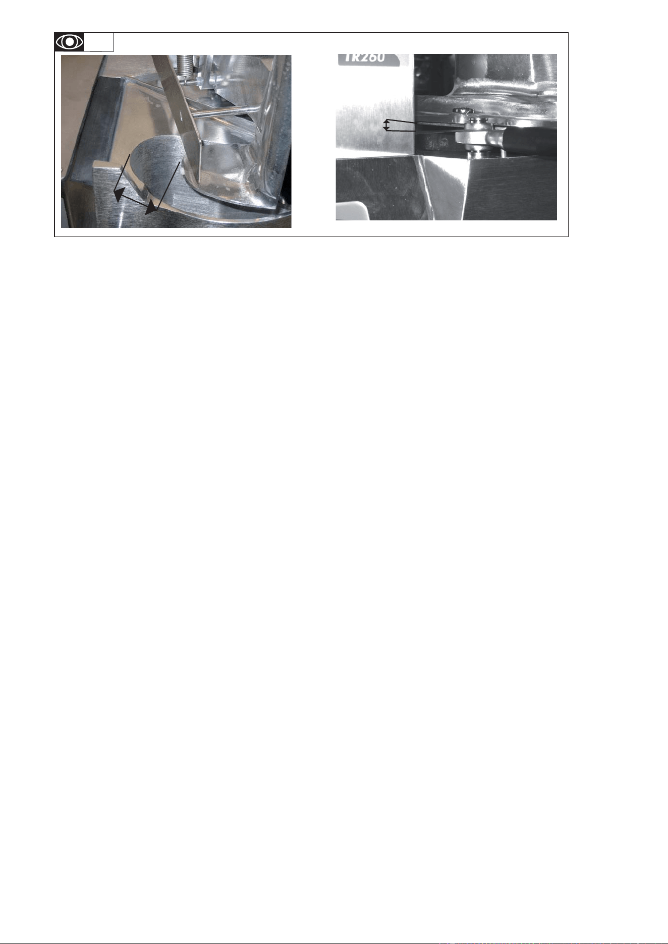
6.3 ADJUSTMENT OF THE SAFETY DEVICES
•
Check that the safety devices are operating correctly prior to
each use. The motor should stop within less than 2 seconds.
- When the lid is opened, dimension E at 18 mm max,
- when the feed arm is opened, if the gap F is at maximum 60
mm from the edge of the feed hopper.
• If any one of the three safety devices does not work:
- do not use the machine
- have it adjusted by the service department of your local dealer.
7 TR260 GB 10 07
6.4
Residual Voltage at the capacitor terminals.
6.4 ELECTRICAL COMPONENTS
see electrical diagrams
•
Access to electrical components.
- Unplug the machine.
•
The capacitors may retain an electrical charge. To avoid taking
any risks when carrying out work, we recommend discharging
them by connecting their terminals with an insulated conductor
(e.g. a screwdriver).
•
Identifi cation of the colours of the wires:
- Power circuit : black (F)
- Control circuit: red (A)
- Phases : L1 / L2 / L3
- Neutral : N
- Earth : green/yellow B/C
•
Identifi cation of the components
CC : Control card
Cpu : Power supply card
S : Sensor
S1 : Lid safety device
S2 : Hopper safety device
CD : Starter condenser
CP : Permanent capacitor
K1 : Relay
Cb : Braking capacitor
M : Motor
Dealer’s stamp
Date of purchase: ...............................................
6.5 ADDRESS FOR MAINTENANCE
We recommend that you contact your machine supplier fi rst
of all.
The manufacturer reserves the right to modify or improve its
products without notice.
For any requests for information or orders for spare parts,
please state the type of machine, the serial number and
the electrical specifi cations
Conformity with regulations
The machine has been designed and manufactured in
conformity with :
- The machine directive 2006/42 EEC.
- The CEM directive 2004/108 EEC.
- 2006/95/EEC: Low Voltage Directive
- 2002/95/EC: Equipment recycling directive
2002/96/CEE « WEEE »
The symbol « » on the product indicates that this product
may not be treated as household waste. Instead it shall be
handed over to the applicable collection point for the recycling
of electrical and electronic equipment. By ensuring this product
is disposed of correctly, you will help prevent potential negative
consequences for the environment and human health, which
could otherwise be caused by inappropriate waste handling
of this product. For more detailed information about recycling
of this product, please contact the sales agent or dealer for
your product, your after-sales service, or the appropriate waste
disposal service.
2006/12/CEE “Waste”
The machine is designed so that it does not contribute, or as
little as possible, to increasing the quantity or harmfulness of the
waste and the risks of pollution.
Make sure to observe the recycling conditions.
94/62/CE “Packaging and packaging waste”
The packaging for the machine is designed so that it does not
contribute, or as little as possible to increasing the quantity or
harmfulness of the waste and the risks of pollution.
Make sure to eliminate the various parts of the packaging in
appropriate recycling centres.
- To the European standards :
EN 60 204-2006 electrical equipment of machines,
EN 1678-1998 vegetable cutters, integrated safety devices.
This conformity is certifi ed by :
- The CE conformity mark, attached to the machine.
- The corresponding CE declaration of conformity, associated
with the warranty.
- This instruction manual, which must be given to the opera-
tor.
Acoustic characteristics :
- The acoustic pressure level measured in accordance with the
test code EN ISO 3743.1-EN ISO 3744 = 74 dBA
Protection indices as per the EN 60529-2000 standard :
- IP55 electrical controls.
- IP23 overall machine.
Integrated safety :
- The machine has been designed and manufactured in com-
pliance with the relevant standards and regulations, mentioned
above.
- Before using the machine, the operator must be trained to
use the machine and informed of any possible residual risks
(personnel work station training obligation).
Food hygiene :
The machine is made from materials that conform to the following
regulations and standards:
- Directive 1935/2005/CEE: Materials and objects in contact with
foodstuffs.
- Standard EN 601-2004: cast aluminium alloy objects in contact
with foodstuffs.
- Directive EN 1672-2 : Prescriptions relating to hygiene
The surfaces of the food area are smooth and easy to clean. Use
detergents that are approved for food hygiene and respect the
instructions for their use.
The machine has been CNERPAC approved for food hygiene as
well as conforming NSF standard 8.
TR260 GB 10 07 8

