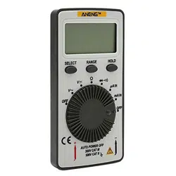
Pocket Digital Multimeter
User’s Manual
AN101
CAT II CAT III
600 V
300 V

Pocket Digital Multimeter
Pocket Digital Multimeter
CONTENTS
1. Safety information
1.
Safety information
1
Warning
1.
1
Preliminary
1
To ensure safe operation, and in order to exploit to
1.
2
During use
2
1.3 Symbols
3
the full functionality of the meter, please follow
1.
4
Maintenance
3
the directions in this section carefully.
2.
Description
4
This multimeter has been designed according to IEC-
2.
1
Names of components
4
1010 concerning electronic measuring instruments
2.
2
Function and range selector
5
with an overvoltage CAT II 600V and pollution 2.
3.
Specifications
5
Follow all safety and operating instructions to ensure
3.
1
General specifications
5
that the meter is used safely and is kept in good
3.
2
Electrical specifications
6
operating condition.
4.
Operating instruction
10
1.1 Preliminary
4.
1
Data hold
10
4.
2
Manual range
10
1.1.1 When using the meter, the user must observe all
4.
3
Switch function
10
normal safety rules concerning:
4.
4
Auto power off
10
• Protection against the dangers of electrical current
4.
5
Preparation for measurement
11
• Protection of the meter against misuse
4.
6
Measuring ac voltage
11
1.1.2 When the meter is delivered, check if it has been
4.
7
Measuring dc voltage
11
damaged in transit.
4.
8
Measuring resistance
12
1.1.3 When poor condition under harsh preservation or
4.
9
Measuring capacitance
12
shipping conditions caused, inspect and confirm
4.
10Measuring frequency
13
this meter without delay.
4.
11Testing diode
13
1.1.4 Test leads must be in good condition. Before using
4.
12Continuity test
13
verify that the insulation on test leads is not
4.
13 Induced voltage test
14
damaged and/or the leads wire is not exposed.
5.
Maintenance
14
1.1.5 Full compliance with safety standards can be
5.
1
Battery replacement
14
guaranteed only if used with test leads supplied.
5.
2
Test leads replacement
16
If necessary, they must be replaced with the same
5.
3
Store of test leads
16
model or same electric ratings.
6.
Accessories
16
01
Pocket Digital Multimeter
Pocket Digital Multimeter
CONTENTS
1. Safety information
1.
Safety information
1
Warning
1.
1
Preliminary
1
To ensure safe operation, and in order to exploit to
1.
2
During use
2
1.3 Symbols
3
the full functionality of the meter, please follow
1.
4
Maintenance
3
the directions in this section carefully.
2.
Description
4
This multimeter has been designed according to IEC-
2.
1
Names of components
4
1010 concerning electronic measuring instruments
2.
2
Function and range selector
5
with an overvoltage CAT II 600V and pollution 2.
3.
Specifications
5
Follow all safety and operating instructions to ensure
3.
1
General specifications
5
that the meter is used safely and is kept in good
3.
2
Electrical specifications
6
operating condition.
4.
Operating instruction
10
1.1 Preliminary
4.
1
Data hold
10
4.
2
Manual range
10
1.1.1 When using the meter, the user must observe all
4.
3
Switch function
10
normal safety rules concerning:
4.
4
Auto power off
10
• Protection against the dangers of electrical current
4.
5
Preparation for measurement
11
• Protection of the meter against misuse
4.
6
Measuring ac voltage
11
1.1.2 When the meter is delivered, check if it has been
4.
7
Measuring dc voltage
11
damaged in transit.
4.
8
Measuring resistance
12
1.1.3 When poor condition under harsh preservation or
4.
9
Measuring capacitance
12
shipping conditions caused, inspect and confirm
4.
10Measuring frequency
13
this meter without delay.
4.
11Testing diode
13
1.1.4 Test leads must be in good condition. Before using
4.
12Continuity test
13
verify that the insulation on test leads is not
4.
13 Induced voltage test
14
damaged and/or the leads wire is not exposed.
5.
Maintenance
14
1.1.5 Full compliance with safety standards can be
5.
1
Battery replacement
14
guaranteed only if used with test leads supplied.
5.
2
Test leads replacement
16
If necessary, they must be replaced with the same
5.
3
Store of test leads
16
model or same electric ratings.
6.
Accessories
16
01

Pocket Digital Multimeter
1.2 During use
1.2.1 Never exceed the protection limit values indicated in
specifications for each range of measurement.
1.2.2 When the meter is linked to a measurement circuit, do
not touch unused terminals.
1.2.3 Do not measure voltage if the voltage on the
terminals exceeds 600V above earth ground.
1.2.4 Always be careful when working with voltages above
60V DC or 30V AC rms, keep fingers behind the probe
barriers while measuring.
1.2.5 Never connect the meter leads across a voltage
source while the function switch is in the current,
resistance, diode or continuity mode. Doing so can
damage the meter.
1.2.6 Before stir the transform switch to change functions,
disconnect test leads from the circuit under test.
1.2.7 When carrying out measurements on TV or
switching power circuits always remember that there
may be high amplitude voltages pulses at test points,
which can damage the meter.
1.2.8 Never perform resistance measurements on live
circuits.
1.2.9 If any faults or abnormalities are observed, the
meter can not be used any more and it has to be
checked out.
1.2.10 Never use the meter unless the rear case is in
place and fastened fully.
1.2.11 Please do not store or use meter in areas
exposed to direct sunlight, high temperature,
humidity or condensation.
02
Pocket Digital Multimeter
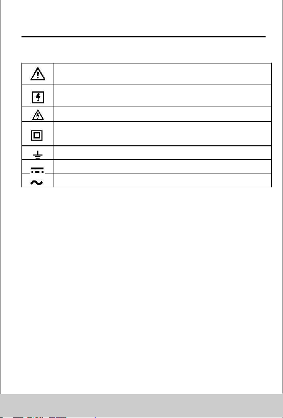
1.3 Symbols
Note-Important safety information, refer to the
instruction manual.
Application around and removal from UNINSULATED
HAZARDOUS LIVE conductors is permitted.
Caution, possibility of electric shock
Equipment protected throughout by double
insulation or reinforced insulation.
Earth (ground) TERMINAL
Direct current
Alternating current
CAT III: MEASUREMENT CATEGORY III is applicable to
test and measuring circuits connected to the distribution
part of the building's low-voltage MAINS installation.
CAT II: MEASUREMENT CATEGORY II is applicable to
test and measuring circuits connected directly to utilization
points (socket outlets and similar points) of the low-voltage
MAINS installation.
1.4 Maintenance
1.4.1 Please do not attempt to adjust or repair the meter by
removing the rear case while voltage is being applied. A
technician who fully understands danger involved should
only carry out such actions.
1.4.2 Before opening the case of the meter, always
disconnect test leads from all sources of electric current.
1.4.3 Do not use abrasives or solvents on the meter, use
a damp cloth and mild detergent only.
1.4.4 ALWAYS set the power switch to the OFF position
03
Pocket Digital Multimeter
1.2 During use
1.2.1 Never exceed the protection limit values indicated in
specifications for each range of measurement.
1.2.2 When the meter is linked to a measurement circuit, do
not touch unused terminals.
1.2.3 Do not measure voltage if the voltage on the
terminals exceeds 600V above earth ground.
1.2.4 Always be careful when working with voltages above
60V DC or 30V AC rms, keep fingers behind the probe
barriers while measuring.
1.2.5 Never connect the meter leads across a voltage
source while the function switch is in the current,
resistance, diode or continuity mode. Doing so can
damage the meter.
1.2.6 Before stir the transform switch to change functions,
disconnect test leads from the circuit under test.
1.2.7 When carrying out measurements on TV or
switching power circuits always remember that there
may be high amplitude voltages pulses at test points,
which can damage the meter.
1.2.8 Never perform resistance measurements on live
circuits.
1.2.9 If any faults or abnormalities are observed, the
meter can not be used any more and it has to be
checked out.
1.2.10 Never use the meter unless the rear case is in
place and fastened fully.
1.2.11 Please do not store or use meter in areas
exposed to direct sunlight, high temperature,
humidity or condensation.
02
Pocket Digital Multimeter
1.3 Symbols
Note-Important safety information, refer to the
instruction manual.
Application around and removal from UNINSULATED
HAZARDOUS LIVE conductors is permitted.
Caution, possibility of electric shock
Equipment protected throughout by double
insulation or reinforced insulation.
Earth (ground) TERMINAL
Direct current
Alternating current
CAT III: MEASUREMENT CATEGORY III is applicable to
test and measuring circuits connected to the distribution
part of the building's low-voltage MAINS installation.
CAT II: MEASUREMENT CATEGORY II is applicable to
test and measuring circuits connected directly to utilization
points (socket outlets and similar points) of the low-voltage
MAINS installation.
1.4 Maintenance
1.4.1 Please do not attempt to adjust or repair the meter by
removing the rear case while voltage is being applied. A
technician who fully understands danger involved should
only carry out such actions.
1.4.2 Before opening the case of the meter, always
disconnect test leads from all sources of electric current.
1.4.3 Do not use abrasives or solvents on the meter, use
a damp cloth and mild detergent only.
1.4.4 ALWAYS set the power switch to the OFF position
03
Pocket Digital Multimeter
when the meter is not in use.
1.4.5 If the meter is to be stored for a long period of time,
the batteries should be removed to prevent damage to
the unit.
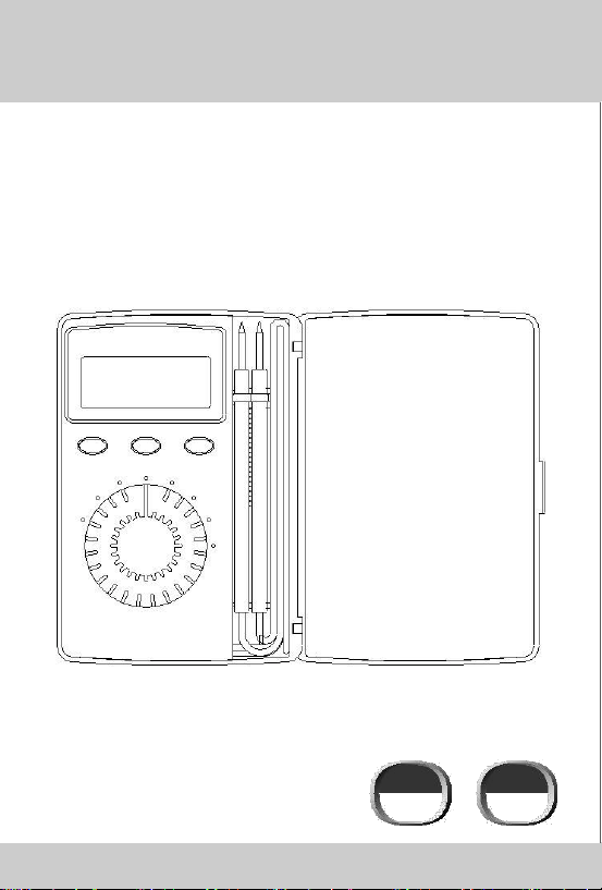
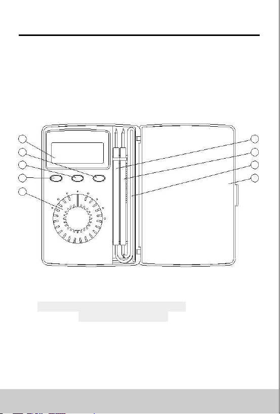
2.Description
2.1 Names of components
1
6
2
7
3
8
4
9
5
LCD Display
(HOLD)Data HOLD Button
(RANGE)Manual range switch button
(SELECT)Function switch button
Transform Switch
Red Test Lead
Black Test Lead
Test Lead Store Space
Cover
04
Pocket Digital Multimeter
2.2 Function and range selector
-This meter is a portable professional measuring
instrument with perfect LCD.
-This meter has function of auto range and data hold.
-When using, it can show ranges engineering unit
enunciators measuring results.
-This meter has function of auto power off.
5. Specifications
Accuracy is specified for a period of year after calibration and
at 18°C to 28°C(64°F to 82°F) with relative humidity to 75%.
3.1 General specifications
3.1.1 It includes 7 function with 29 ranges.
3.1.2 Auto ranges.
3.1.3 Overrange protection for all ranges.
3.1.4 Max. Voltage Between Terminals And Earth
Ground: 600V DC or rms AC
3.1.5 Operating Altitude: 2000 meters (7000 ft.)
maximum
3.1.6 Display: LCD
3.1.7 Max. Show Value:
(9210:1999;9216:4000) counts max
3.1.8 Polarity Indication: ‘-’indicates negative polarity.
3.1.9 Overrange Indication: Display ‘0L’ or ‘-0L’
3.1.10 Sampling Time: approx. 0.4 second
3.1.11 Unit showing: showing of function and
electrical capacity.
3.1.12 Auto power off time: 15 min.
3.1.13 Power Supply: 3V (CR2032 battery) ×1
3.1.14 Low Battery Indication: “ ”displayed
3.1.15 Temperature Factor: < 0.1×Accuracy /°C
3.1.16 Operating Temperature: 0°C to 40°C
(32°F to 104°F)
05

Pocket Digital Multimeter
when the meter is not in use.
1.4.5 If the meter is to be stored for a long period of time,
the batteries should be removed to prevent damage to
the unit.
2.Description
2.1 Names of components
1
6
2
7
3
8
4
9
5
LCD Display
(HOLD)Data HOLD Button
(RANGE)Manual range switch button
(SELECT)Function switch button
Transform Switch
Red Test Lead
Black Test Lead
Test Lead Store Space
Cover
04
Pocket Digital Multimeter
2.2 Function and range selector
-This meter is a portable professional measuring
instrument with perfect LCD.
-This meter has function of auto range and data hold.
-When using, it can show ranges engineering unit
enunciators measuring results.
-This meter has function of auto power off.
5. Specifications
Accuracy is specified for a period of year after calibration and
at 18°C to 28°C(64°F to 82°F) with relative humidity to 75%.
3.1 General specifications
3.1.1 It includes 7 function with 29 ranges.
3.1.2 Auto ranges.
3.1.3 Overrange protection for all ranges.
3.1.4 Max. Voltage Between Terminals And Earth
Ground: 600V DC or rms AC
3.1.5 Operating Altitude: 2000 meters (7000 ft.)
maximum
3.1.6 Display: LCD
3.1.7 Max. Show Value:
(9210:1999;9216:4000) counts max
3.1.8 Polarity Indication: ‘-’indicates negative polarity.
3.1.9 Overrange Indication: Display ‘0L’ or ‘-0L’
3.1.10 Sampling Time: approx. 0.4 second
3.1.11 Unit showing: showing of function and
electrical capacity.
3.1.12 Auto power off time: 15 min.
3.1.13 Power Supply: 3V (CR2032 battery) ×1
3.1.14 Low Battery Indication: “ ”displayed
3.1.15 Temperature Factor: < 0.1×Accuracy /°C
3.1.16 Operating Temperature: 0°C to 40°C
(32°F to 104°F)
05
Pocket Digital Multimeter
3.1.17 Storage Temperature: -10°C to 50°C
(10°F to 122°F)
3.1.18 Dimension: 126×80×19mm
3.1.19 Weight: approximate 100g (including battery)
3.2 Electrical Specifications
Circumstance Temperature: 23±5°C
Relative Humidity: < 70%
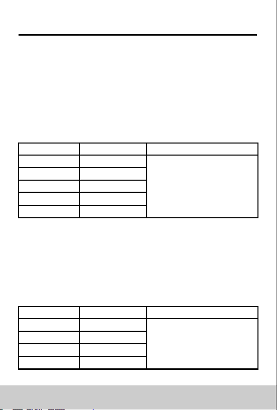
3.2.1 Dc voltage
Range
Resolution
Accuracy
400mV
0.1mV
4V
1mV
±(0.7% of rdg + 2digits)
40V
10mV
400V
100mV
600V
1V
-Input Impedance: 10M
Max. Input Voltage: 600V DC or rms AC
NOTE:
At the little voltage range, the meter will show unsteady
reading when test leads haven't reach the circuit, it's normal
because the meter is very sensitivity. When test leads
touch the circuit, you can get the true reading.
3.2.2 Ac voltage
Range
Resolution
Accuracy
4V
1mV
40V
10mV
±(0.7% of rdg + 2digits)
400V
100mV
600V
1V
-Input Impedance: 10M
06
Pocket Digital Multimeter
Max. Input Voltage: 600V DC or rms AC
Frequency Range: 40 to 1kHz
Response: Average, calibrated in rms of sine wave
NOTE:
At the little voltage range, the meter will show unsteady
reading when test leads haven't reach the circuit, it's normal
because the meter is very sensitivity. When test leads
touch the circuit, you can get the true reading.
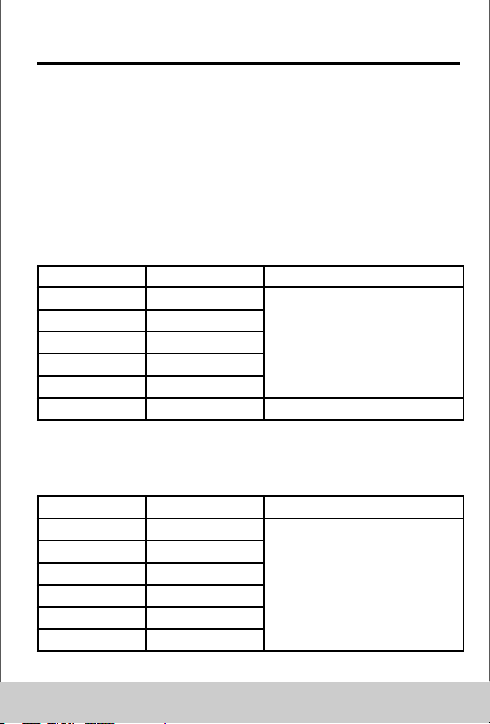
3.2.3 Resistance
Range
Resolution
Accuracy
400Ω
0.1Ω
4kΩ
1Ω
±(1.2% of rdg + 2digits)
40kΩ
10Ω
400kΩ
100Ω
4MΩ
1kΩ
40MΩ
10kΩ
±(2.0% of rdg + 5digits)
-Open Circuit Voltage: 0.25V
- Overload Protection: 250V DC or rms AC
3.2.4 Capacitance(for 9216)
Range
Resolution
Accuracy
4nF
1pF
40nF
10pF
400nF
0.1nF
±(3.0% of rdg + 3digits)
4μF
1nF
40μF
10nF
400μF
100nF
Overload Protection: 250V DC or rms AC
07
Pocket Digital Multimeter
3.1.17 Storage Temperature: -10°C to 50°C
(10°F to 122°F)
3.1.18 Dimension: 126×80×19mm
3.1.19 Weight: approximate 100g (including battery)
3.2 Electrical Specifications
Circumstance Temperature: 23±5°C
Relative Humidity: < 70%
3.2.1 Dc voltage
Range
Resolution
Accuracy
400mV
0.1mV
4V
1mV
±(0.7% of rdg + 2digits)
40V
10mV
400V
100mV
600V
1V
-Input Impedance: 10M
Max. Input Voltage: 600V DC or rms AC
NOTE:
At the little voltage range, the meter will show unsteady
reading when test leads haven't reach the circuit, it's normal
because the meter is very sensitivity. When test leads
touch the circuit, you can get the true reading.
3.2.2 Ac voltage
Range
Resolution
Accuracy
4V
1mV
40V
10mV
±(0.7% of rdg + 2digits)
400V
100mV
600V
1V
-Input Impedance: 10M
06
Pocket Digital Multimeter
Max. Input Voltage: 600V DC or rms AC
Frequency Range: 40 to 1kHz
Response: Average, calibrated in rms of sine wave
NOTE:
At the little voltage range, the meter will show unsteady
reading when test leads haven't reach the circuit, it's normal
because the meter is very sensitivity. When test leads
touch the circuit, you can get the true reading.
3.2.3 Resistance
Range
Resolution
Accuracy
400Ω
0.1Ω
4kΩ
1Ω
±(1.2% of rdg + 2digits)
40kΩ
10Ω
400kΩ
100Ω
4MΩ
1kΩ
40MΩ
10kΩ
±(2.0% of rdg + 5digits)
-Open Circuit Voltage: 0.25V
- Overload Protection: 250V DC or rms AC
3.2.4 Capacitance(for 9216)
Range
Resolution
Accuracy
4nF
1pF
40nF
10pF
400nF
0.1nF
±(3.0% of rdg + 3digits)
4μF
1nF
40μF
10nF
400μF
100nF
Overload Protection: 250V DC or rms AC
07
Pocket Digital Multimeter
3.2.5 Frequency(for 9216)
Range
Resolution
Accuracy
40Hz
0.01Hz
±(1.5% of rdg + 5digits)
400Hz
0.1Hz
±(1.5% of rdg + 5digits)
4kHz
1Hz
±(1.5% of rdg + 5digits)
40kHz
10Hz
±(2.0% of rdg + 5digits)
400kHz
100Hz
±(2.0% of rdg + 5digits)
4MHz
1kHz
±(5.0% of rdg + 5digits)
- By Hz range:
Input Voltage range: 0.5V – 10V rms AC (Input voltage
must be enlarged with increasing frequency under
measurement)
Overload protection: 250V DC or rms AC -
By V range:
Input Voltage range: 0.5V – 600V rms AC (Input voltage
must be enlarged with increasing frequency under
measurement)
Input Impedance: 10M
Max. Input Voltage: 600V DC or rms AC
NOTE:
When measuring frequency, the range by Hz range is
larger than by Hz of Voltage range, but the value
measured beyond the range is just for reference.
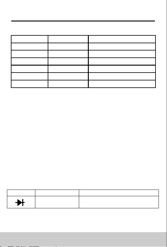
3.2.6 Diode
Range
Resolution
Accuracy
1mV
Display: read approximate
forward voltage of diode
08
Pocket Digital Multimeter
Forward DC Current approximate 1mA Reversed DC
Voltage approximates 1.5V
Overload Protection: 250V DC or rms AC
3.2.7 Continuity
Range Function
Built-in buzzer will sound, if resistance is
lower than 50Ω.
- Open circuit voltage approximate: 0.5V
- Overload Protection: 250V DC or rms AC
3.2.8 DC Current
Range
Resolution
Accuracy
200uA(9210)
0.1uA
±(1% of rdg + 5digits)
2000uA(9210)
1uA
±(1% of rdg + 5digits)
40mA
10uA
±(1% of rdg + 5digits)
200mA
100uA
±(1.5% of rdg + 5digits)
Overload protection: 0.2A/250V fuse
3.2.9 AC Current
Range
Resolution
Accuracy
200uA(9210)
0.1uA
±(1.2% of rdg + 5digits)
2000uA(9210)
1uA
±(1.2% of rdg + 5digits)
40mA
10uA
±(1.2% of rdg + 5digits)
200mA
100uA
±(2% of rdg + 5digits)
Overload protection: 0.2A/250V fuse
Frequency range: 40Hz to 400Hz
Display: average response (effective value of sine
wave)
09
Pocket Digital Multimeter
3.2.5 Frequency(for 9216)
Range
Resolution
Accuracy
40Hz
0.01Hz
±(1.5% of rdg + 5digits)
400Hz
0.1Hz
±(1.5% of rdg + 5digits)
4kHz
1Hz
±(1.5% of rdg + 5digits)
40kHz
10Hz
±(2.0% of rdg + 5digits)
400kHz
100Hz
±(2.0% of rdg + 5digits)
4MHz
1kHz
±(5.0% of rdg + 5digits)
- By Hz range:
Input Voltage range: 0.5V – 10V rms AC (Input voltage
must be enlarged with increasing frequency under
measurement)
Overload protection: 250V DC or rms AC -
By V range:
Input Voltage range: 0.5V – 600V rms AC (Input voltage
must be enlarged with increasing frequency under
measurement)
Input Impedance: 10M
Max. Input Voltage: 600V DC or rms AC
NOTE:
When measuring frequency, the range by Hz range is
larger than by Hz of Voltage range, but the value
measured beyond the range is just for reference.
3.2.6 Diode
Range
Resolution
Accuracy
1mV
Display: read approximate
forward voltage of diode
08
Pocket Digital Multimeter
Forward DC Current approximate 1mA Reversed DC
Voltage approximates 1.5V
Overload Protection: 250V DC or rms AC
3.2.7 Continuity
Range Function
Built-in buzzer will sound, if resistance is
lower than 50Ω.
- Open circuit voltage approximate: 0.5V
- Overload Protection: 250V DC or rms AC
3.2.8 DC Current
Range
Resolution
Accuracy
200uA(9210)
0.1uA
±(1% of rdg + 5digits)
2000uA(9210)
1uA
±(1% of rdg + 5digits)
40mA
10uA
±(1% of rdg + 5digits)
200mA
100uA
±(1.5% of rdg + 5digits)
Overload protection: 0.2A/250V fuse
3.2.9 AC Current
Range
Resolution
Accuracy
200uA(9210)
0.1uA
±(1.2% of rdg + 5digits)
2000uA(9210)
1uA
±(1.2% of rdg + 5digits)
40mA
10uA
±(1.2% of rdg + 5digits)
200mA
100uA
±(2% of rdg + 5digits)
Overload protection: 0.2A/250V fuse
Frequency range: 40Hz to 400Hz
Display: average response (effective value of sine
wave)
09

Pocket Digital Multimeter
Operating instruction
4.1 Data hold(HOLD)
If you need data hold when measuring, you can put on
“HOLD”; it will hold the reading; if you put the button again,
data hold is not continue.
4.2 Manual range(RANGE)
Press this key to switch the range to manual state.
Long press this key to restore the automatic range
state
4.3 Switch function(SELECT)
Press this key to achieve ac and dc current switching and
resistance - diode - short circuit/break function switching
4.4 Auto power off
If no operation within fifteen minutes after power is on,
meter will auto power off with five short sounds and one
long.
After auto power off, if stir the transform switch or
putdown any button of "HOLD”, “RANGE”, “SELECT”,
meter will recover the working condition.
10
Pocket Digital Multimeter
4.5 Preparation for measurement
4.
5.1 Stir the transform switch. If the battery voltage is less
than 2.4V, display will show “ ”, the battery should be
changed at this time.
4.5.2 The “ ” besides the input lead shows that the input
voltage or current should be less than specification on the
sticker of the meter to protect the inner circuit from
damaging.
4.5.3 Select a transform switch accordingly for the item to
be measured.
4.6 Measuring ac voltage
4.6.1 Set the transform switch at the AC V range position.
4.6.2 Connect test leads across the source or load under
measurement.
4.6.3 You can get reading from LCD.
NOTE:
“ ” means you can’t input the voltage which more
than 600V DC or 600V rms AC, it’s possible to show
higher voltage, but it’s may destroy the inner circuit.
Pay attention not to get an electric shock when
measuring high voltage.
4.7 Measuring dc voltage
4. 7.1 Set the transform switch at the DC V range position.
4.7.2 Connect test leads across the source or load under
measurement.
4.7.3 You can get reading from LCD. The polarity of the red
lead connection will be indicated along with the
voltage value.
11

Pocket Digital Multimeter
Operating instruction
4.1 Data hold(HOLD)
If you need data hold when measuring, you can put on
“HOLD”; it will hold the reading; if you put the button again,
data hold is not continue.
4.2 Manual range(RANGE)
Press this key to switch the range to manual state.
Long press this key to restore the automatic range
state
4.3 Switch function(SELECT)
Press this key to achieve ac and dc current switching and
resistance - diode - short circuit/break function switching
4.4 Auto power off
If no operation within fifteen minutes after power is on,
meter will auto power off with five short sounds and one
long.
After auto power off, if stir the transform switch or
putdown any button of "HOLD”, “RANGE”, “SELECT”,
meter will recover the working condition.
10
Pocket Digital Multimeter
4.5 Preparation for measurement
4.
5.1 Stir the transform switch. If the battery voltage is less
than 2.4V, display will show “ ”, the battery should be
changed at this time.
4.5.2 The “ ” besides the input lead shows that the input
voltage or current should be less than specification on the
sticker of the meter to protect the inner circuit from
damaging.
4.5.3 Select a transform switch accordingly for the item to
be measured.
4.6 Measuring ac voltage
4.6.1 Set the transform switch at the AC V range position.
4.6.2 Connect test leads across the source or load under
measurement.
4.6.3 You can get reading from LCD.
NOTE:
“ ” means you can’t input the voltage which more
than 600V DC or 600V rms AC, it’s possible to show
higher voltage, but it’s may destroy the inner circuit.
Pay attention not to get an electric shock when
measuring high voltage.
4.7 Measuring dc voltage
4. 7.1 Set the transform switch at the DC V range position.
4.7.2 Connect test leads across the source or load under
measurement.
4.7.3 You can get reading from LCD. The polarity of the red
lead connection will be indicated along with the
voltage value.
11
Pocket Digital Multimeter
NOTE:
“ ” means you can’t input the voltage which more
than 600V DC or 600V rms AC, it’s possible to show
higher voltage, but it’s may destroy the inner circuit.
Pay attention not to get an electric shock when
measuring high voltage.
4.8 Measuring resistance
4.8.1 Set the transform switch at the desired range.
4.8.2 Connect test leads across the resistance under
measurement.
4.8.3 You can get reading from LCD.
NOTE:
For measuring resistance above 1M, the meter may
take a few seconds to get stable reading.
When the input is not connected, i.e. at open circuit, the
figure ‘OL’ will be displayed for the overrange condition.
When checking in-circuit resistance, be sure the
circuit under test has all power removed and that all
capacitors have been discharged fully.
4.9 Measuring capacitance(for 9216)
4.9.1 Set the transform switch at the range position.
4.9.2 Connect test leads across the capacitance under
measurement.
4.9.3 You can get reading from LCD.
Warning
To avoid electric shock, be sure the capacitors have been
discharged fully before measuring the capacitance of a
capacitor.
12
Pocket Digital Multimeter
NOTE:
It takes certain time (200μF range 30 seconds) to
steady the reading when measuring high capacity.
4.10 Measuring frequency
4.10.1 Set the transform switch at the Hz range position
4.10.2 Connect test leads across the source or load
under measurement.
4.10.3 You can get reading from LCD.
4.11 Testing diode
4.11.1 Set the transform switch at the range position.
4.11.2 Connect the red lead to the anode, the black lead to
the cathode of the diode under testing.
4.11.3 You can get reading from LCD.
NOTE:
1.The meter will show the approximate forward voltage
drop of the diode.
2.If the lead connection is reversed, only figure‘0L’will be
displayed.
4.12 Continuity test
4.12.1 Set the transform switch at the range position.
4.12.2 Connect test leads across two points of the
circuit under testing.
4.12.3 If continuity exists(i.e., resistance less than
about 50Ω), built-in buzzer will sound.
4.12.4 You can get reading from LCD.
NOTE:
If the input open circuit(or the circuit resistance measured
is higher than 400Ω), then the figure‘0L’ will be displayed.
13

Pocket Digital Multimeter
NOTE:
“ ” means you can’t input the voltage which more
than 600V DC or 600V rms AC, it’s possible to show
higher voltage, but it’s may destroy the inner circuit.
Pay attention not to get an electric shock when
measuring high voltage.
4.8 Measuring resistance
4.8.1 Set the transform switch at the desired range.
4.8.2 Connect test leads across the resistance under
measurement.
4.8.3 You can get reading from LCD.
NOTE:
For measuring resistance above 1M, the meter may
take a few seconds to get stable reading.
When the input is not connected, i.e. at open circuit, the
figure ‘OL’ will be displayed for the overrange condition.
When checking in-circuit resistance, be sure the
circuit under test has all power removed and that all
capacitors have been discharged fully.
4.9 Measuring capacitance(for 9216)
4.9.1 Set the transform switch at the range position.
4.9.2 Connect test leads across the capacitance under
measurement.
4.9.3 You can get reading from LCD.
Warning
To avoid electric shock, be sure the capacitors have been
discharged fully before measuring the capacitance of a
capacitor.
12
Pocket Digital Multimeter
NOTE:
It takes certain time (200μF range 30 seconds) to
steady the reading when measuring high capacity.
4.10 Measuring frequency
4.10.1 Set the transform switch at the Hz range position
4.10.2 Connect test leads across the source or load
under measurement.
4.10.3 You can get reading from LCD.
4.11 Testing diode
4.11.1 Set the transform switch at the range position.
4.11.2 Connect the red lead to the anode, the black lead to
the cathode of the diode under testing.
4.11.3 You can get reading from LCD.
NOTE:
1.The meter will show the approximate forward voltage
drop of the diode.
2.If the lead connection is reversed, only figure‘0L’will be
displayed.
4.12 Continuity test
4.12.1 Set the transform switch at the range position.
4.12.2 Connect test leads across two points of the
circuit under testing.
4.12.3 If continuity exists(i.e., resistance less than
about 50Ω), built-in buzzer will sound.
4.12.4 You can get reading from LCD.
NOTE:
If the input open circuit(or the circuit resistance measured
is higher than 400Ω), then the figure‘0L’ will be displayed.
13
Pocket Digital Multimeter
4.13 Induced voltage test(for 9216)
4.13.1. Switch to "NCV" function
4.13.2.The top of the instrument is close to the ac charged
body.
4.13.3.When the sensor at the top of the meter senses the
presence of an alternating current electric field,The internal
buzzer makes a sound and the screen displays the
corresponding induced voltage intensity.
5. Maintenance
5.1 Replacing The Batteries
WARNING
To avoid electric shock, make sure that the test
leads have been clearly move away from the
circuit under measurement before opening the
battery cover of the meter.
WARNING
Do not mix old and new batteries. Do not mix
a
lkaline,
s
tandard (
c
arbon-
z
inc),
o
r
r
echargeable (
n
i-
cad, ni-mh, etc) batteries.
5.1.1 If the sign “ ” appears, it means that the
batteries should be replaced.
5.1.2 Loosen the fixing screw of the battery cover and
remove it.
5.1.3 Replace the exhausted batteries with new ones.
5.1.4 Put the battery cover back and fix it again to its origin
form.
14
Pocket Digital Multimeter
Note:
Do not reverse the polarity of the batteries.
5.2 Replacing Test Leads
Replace test leads if leads become damaged or worn.
WARNING
Use meet EN 61010-031 standard, rated CAT III 600V,
or better test leads.
5.3 Store of test leads
When placing the teat leads in the storing space, first roll
its wire 3 times, then put it into the store space as
illustrated.
6. Accessories
Battery: 3V 2032 1Pcs
Operating Manual 1Pcs
15
Pocket Digital Multimeter
4.13 Induced voltage test(for 9216)
4.13.1. Switch to "NCV" function
4.13.2.The top of the instrument is close to the ac charged
body.
4.13.3.When the sensor at the top of the meter senses the
presence of an alternating current electric field,The internal
buzzer makes a sound and the screen displays the
corresponding induced voltage intensity.
5. Maintenance
5.1 Replacing The Batteries
WARNING
To avoid electric shock, make sure that the test
leads have been clearly move away from the
circuit under measurement before opening the
battery cover of the meter.
WARNING
Do not mix old and new batteries. Do not mix
a
lkaline,
s
tandard (
c
arbon-
z
inc),
o
r
r
echargeable (
n
i-
cad, ni-mh, etc) batteries.
5.1.1 If the sign “ ” appears, it means that the
batteries should be replaced.
5.1.2 Loosen the fixing screw of the battery cover and
remove it.
5.1.3 Replace the exhausted batteries with new ones.
5.1.4 Put the battery cover back and fix it again to its origin
form.
14
Pocket Digital Multimeter
Note:
Do not reverse the polarity of the batteries.
5.2 Replacing Test Leads
Replace test leads if leads become damaged or worn.
WARNING
Use meet EN 61010-031 standard, rated CAT III 600V,
or better test leads.
5.3 Store of test leads
When placing the teat leads in the storing space, first roll
its wire 3 times, then put it into the store space as
illustrated.
6. Accessories
Battery: 3V 2032 1Pcs
Operating Manual 1Pcs
15

00-05-0918