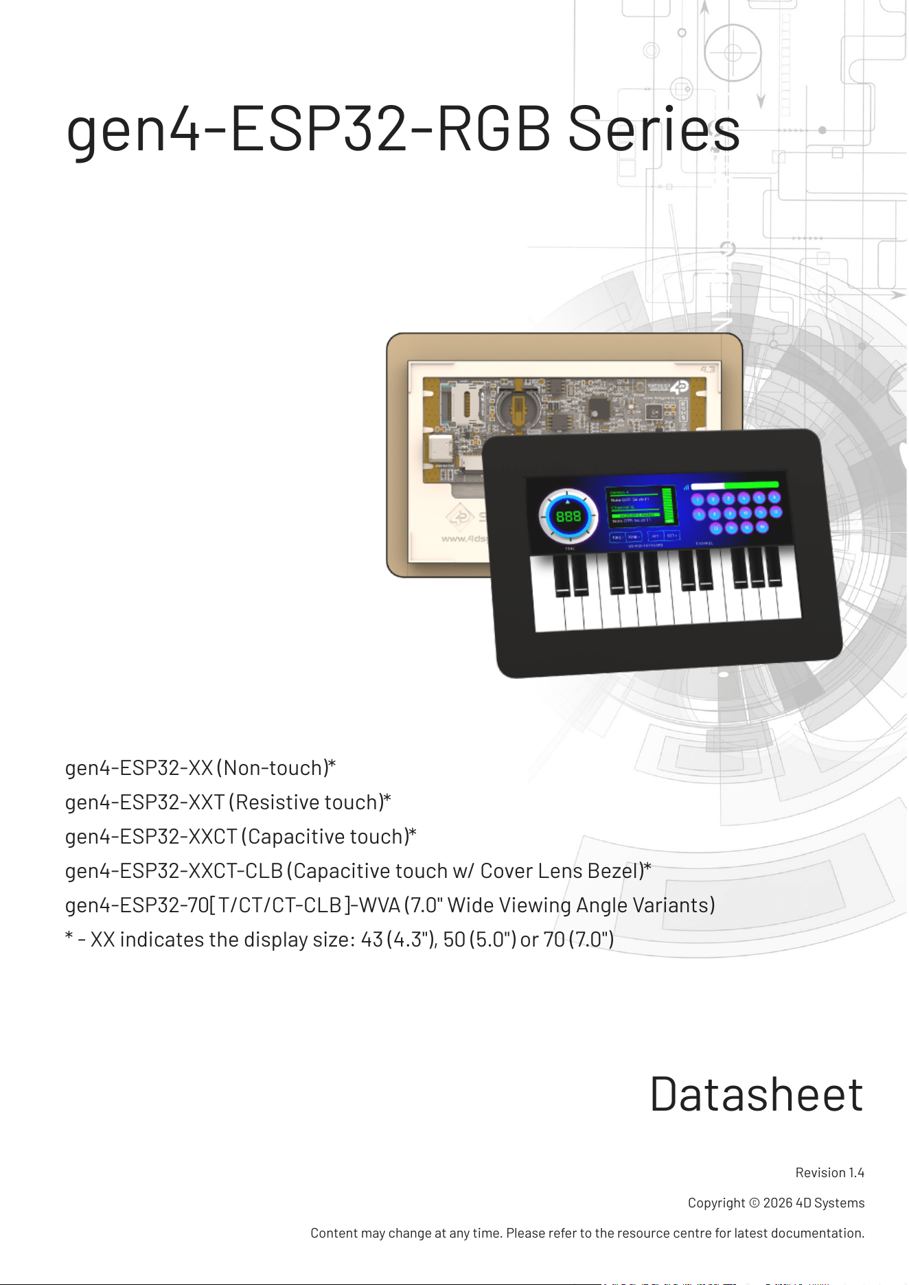
gen4-ESP32-RGB Series
gen4-ESP32-XX (Non-touch)*
gen4-ESP32-XXT (Resistive touch)*
gen4-ESP32-XXCT (Capacitive touch)*
gen4-ESP32-XXCT-CLB (Capacitive touch w/ Cover Lens Bezel)*
gen4-ESP32-70[T/CT/CT-CLB]-WVA (7.0" Wide Viewing Angle Variants)
* - XX indicates the display size: 43 (4.3"), 50 (5.0") or 70 (7.0")
Datasheet
Revision 1.4
Copyright © 2026 4D Systems
Content may change at any time. Please refer to the resource centre for latest documentation.
Contents
41. Description
62. Features
83. Hardware Overview
104. Hardware Interface - Pins
104.1. Serial Ports - 3.3V TTL
104.2. I2C Port - 3.3V TTL
104.3. SPI Port - 3.3V TTL
114.4. General Purpose I/O
154.5. System Pins
164.6. Accessing Other GPIO Pins - Hardware Mods Required
185. Module Features
185.1. ESP32-S3R8 Processor
185.2. Chipsets used
195.3. SD/SDHC Memory Cards
205.4. microSD Socket Usage
215.5. FAT16 vs FAT32
215.6. Wide Viewing Angle (WVA)
226. Display/Module Precautions
237. Hardware Tools
237.1. 4D-UPA
257.2. USB-C Cable
268. Software Tools
268.1. Workshop4 IDE
278.2. Workshop5 IDE
288.3. Workshop Built-in Tools
289. Programming Language
2910. ESP-IDF Development
3011. Display Module Part Numbers
4D Systems
DATASHEET
Page 2 of 46
3112. Cover Lens Bezel - Tape Spec
3113. FFC Cable
3314. Starter Kit
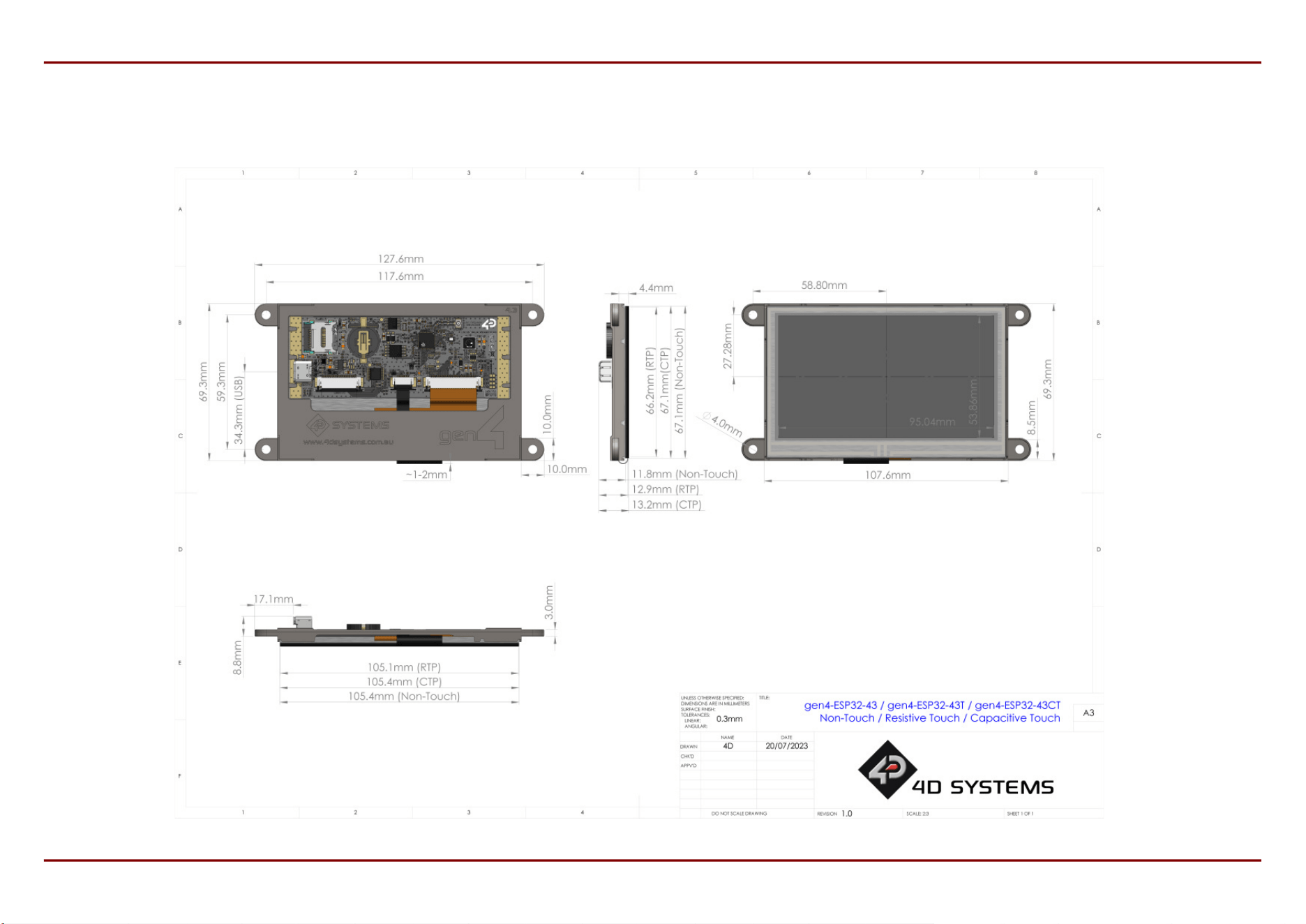
3415. 4.3" Mechanical Details
3415.1. Non-Touch, Resistive and Capacitive
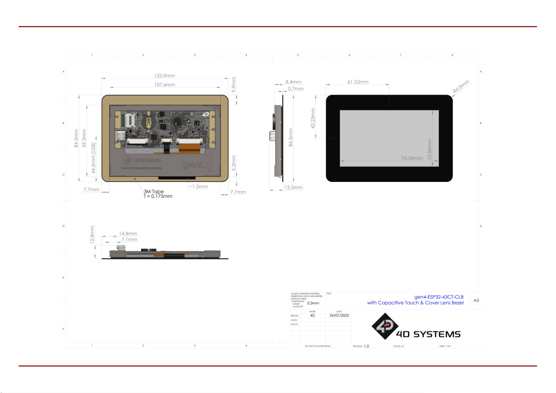
3515.2. Capacitive w/ CLB
3616. 5.0" Mechanical Details
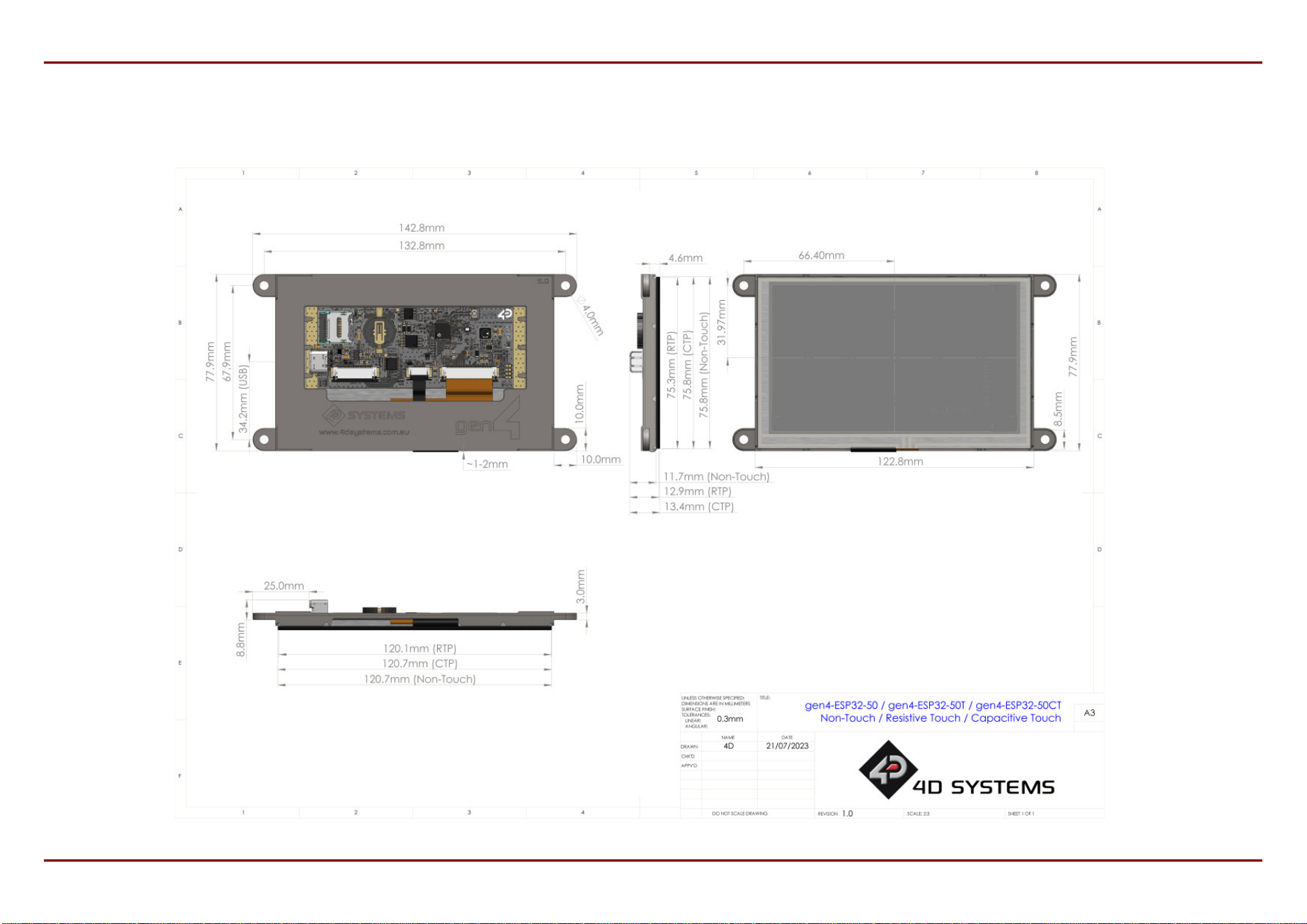
3616.1. Non-Touch, Resistive and Capacitive
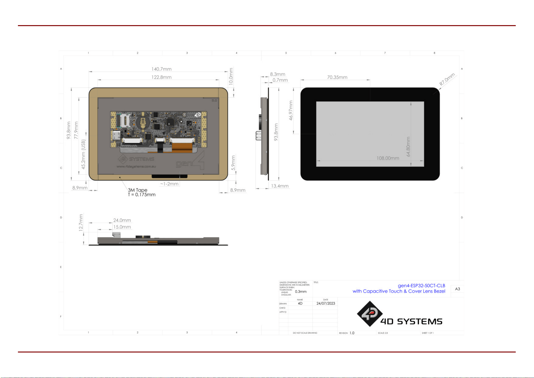
3716.2. Capacitive w/ CLB
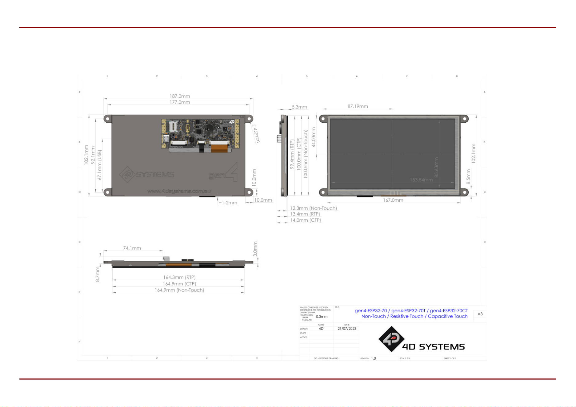
3817. 7.0" Mechanical Details
3817.1. Non-Touch, Resistive and Capacitive
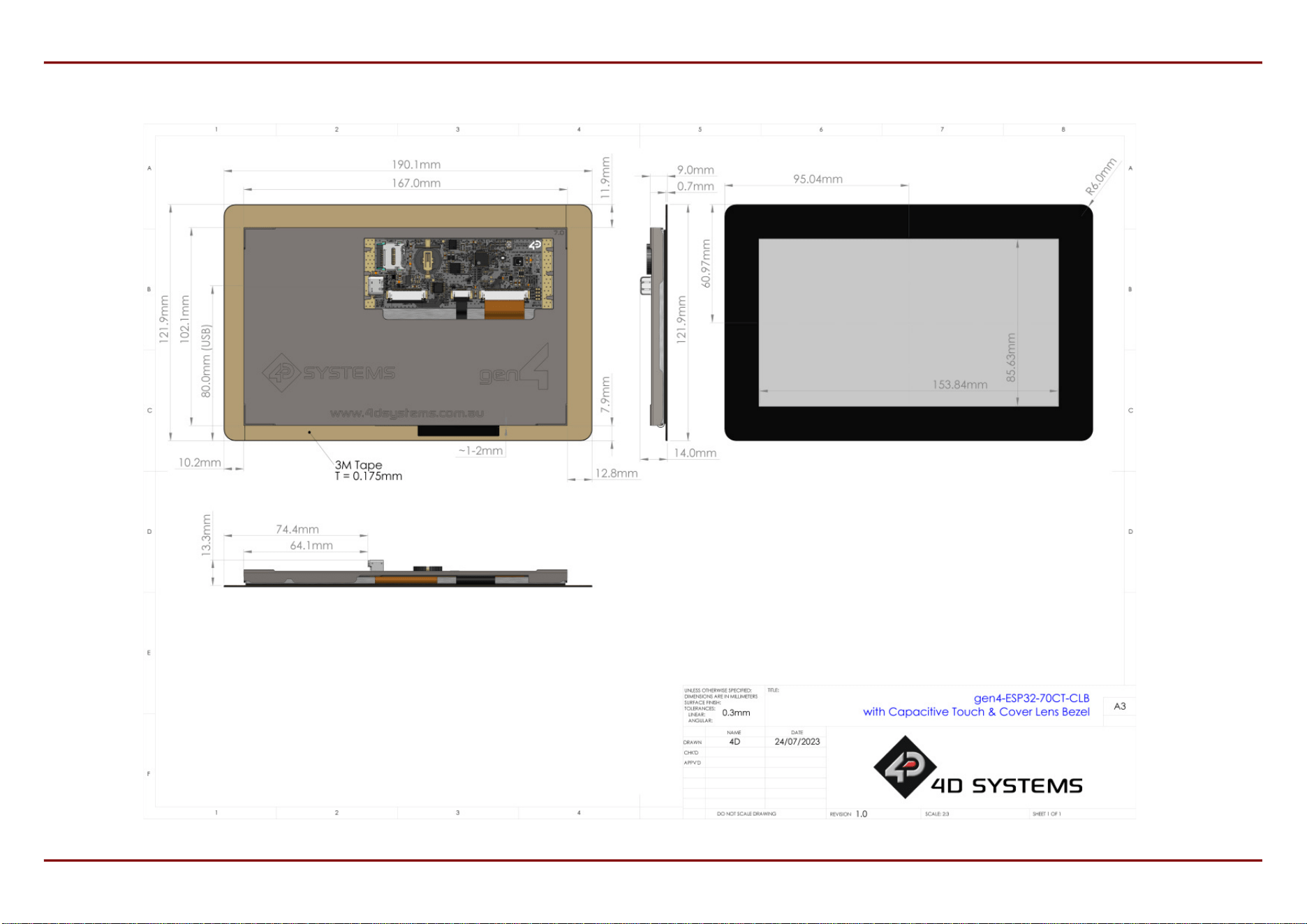
3917.2. Capacitive w/ CLB
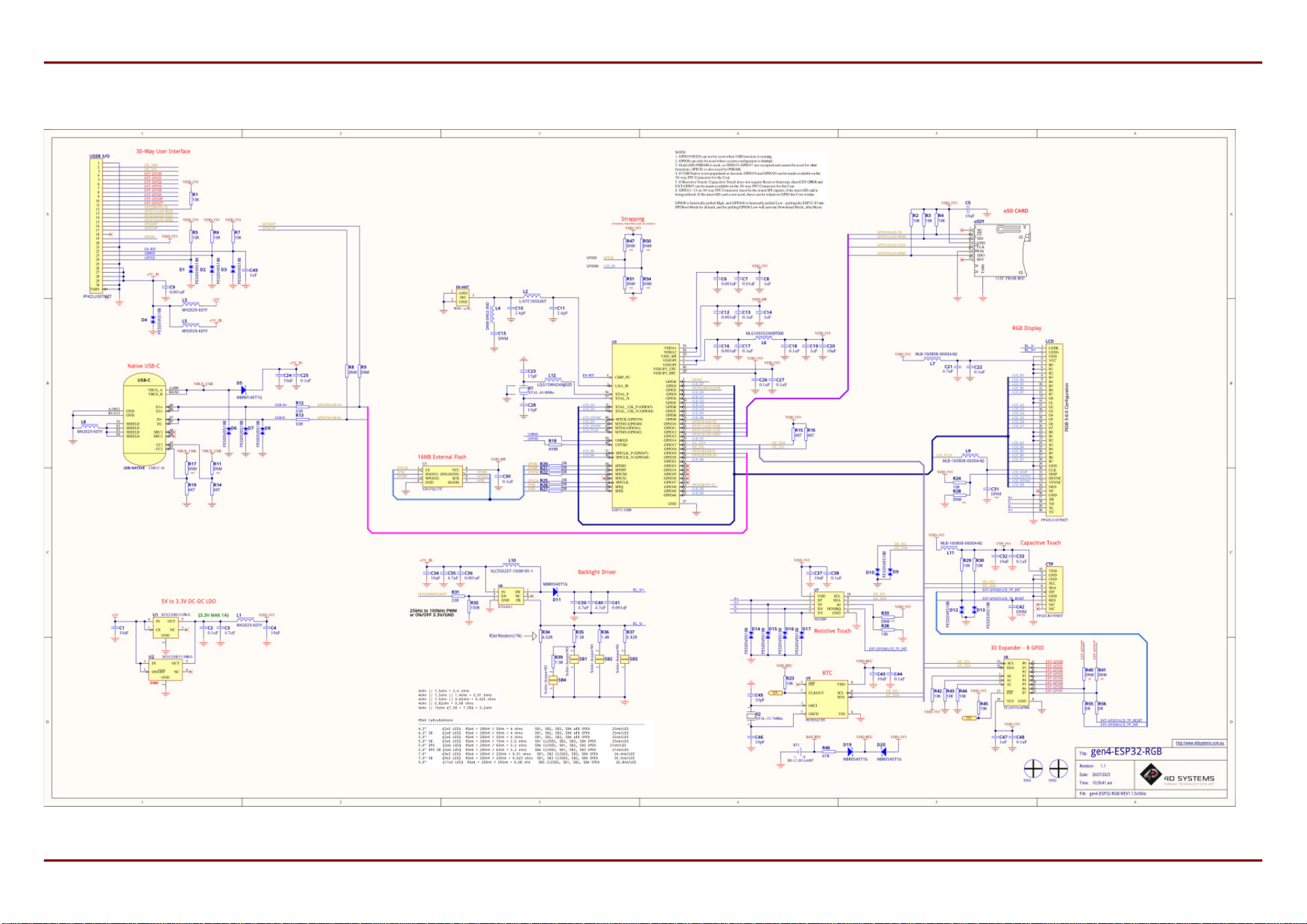
4018. Schematic Circuit Details
4119. Specications
4520. Revision History
4621. Legal Notice
4621.1. Proprietary Information
4621.2. Disclaimer of Warranties & Limitations of Liabilities
4D Systems
DATASHEET
Page 3 of 46

1. Description
The gen4-ESP32 Series of Intelligent Display Modules, is designed and manufactured by 4D Systems.
These display modules are available in 4.3", 5.0" and 7.0", offering an RGB Interface between the ESP32-S3R8
Processor, and the 800x480 resolution TFT LCD Displays. The 4.3" and 5.0" displays are an IPS TFT LCD's, and the
7.0" is a TN TFT LCD. The 7.0" is also available in WVA (Wide Viewing Angle), which brings IPS like performance to a
TN display.
Available in Non-Touch, Resistive Touch, Capacitive Touch, and Capacitive Touch with Cover Lens Bezel (CLB).
The ESP32-S3R8 Processor makes available multiple GPIO which include UART, SPI, I2C, PWM and Analog
functionality, while also serving interfaces for the LCD Touch screen, Real Time Clock, Quad SPI Flash, microSD
Card, 8bit IO Expander and Native USB-C.
The user interface to the gen4-ESP32 series is a 30-pin FPC/ZIF socket, designed for a 30-way 0.5mm pitch FFC
cable, for easy and simple connection to an application or motherboard, or for connecting to accessory boards for
a range of functionality advancements.
This series of boards is compatible with the 4D Systems Workshop4 IDE, utilising the Espressif compiler and 4D
Systems purpose built libraries, allowing a feature rich design and programming experience.
Any code designed and written to run on other 4D Systems display modules, such as modules featuring
GOLDELOX, PICASO, PIXXI or DIABLO-16 Graphics Processors, are unfortunately not compatible with the gen4-
ESP32 range due to being a totally different processor family. However, please contact 4D Systems Support Team
for assistance if you are planning on migrating from a different 4D Systems display model, as there are some
similarities between them - such as the graphics, however a majority of the coding will have to be adapted.
From a mechanical perspective, these gen4-ESP32 modules are physically the same mounting size as other gen4
products by 4D Systems. The only difference is the circuitry used. Overall thickness of these gen4-ESP32 modules
are greater than other gen4 products, due to the USB-C connector and coin cell battery holder for the RTC.
Typically, where ever a different gen4 module had been mounted, a gen4-ESP32 module could t in the same
location.
gen4-ESP32-RGB Series Description
4D Systems
DATASHEET
Page 4 of 46
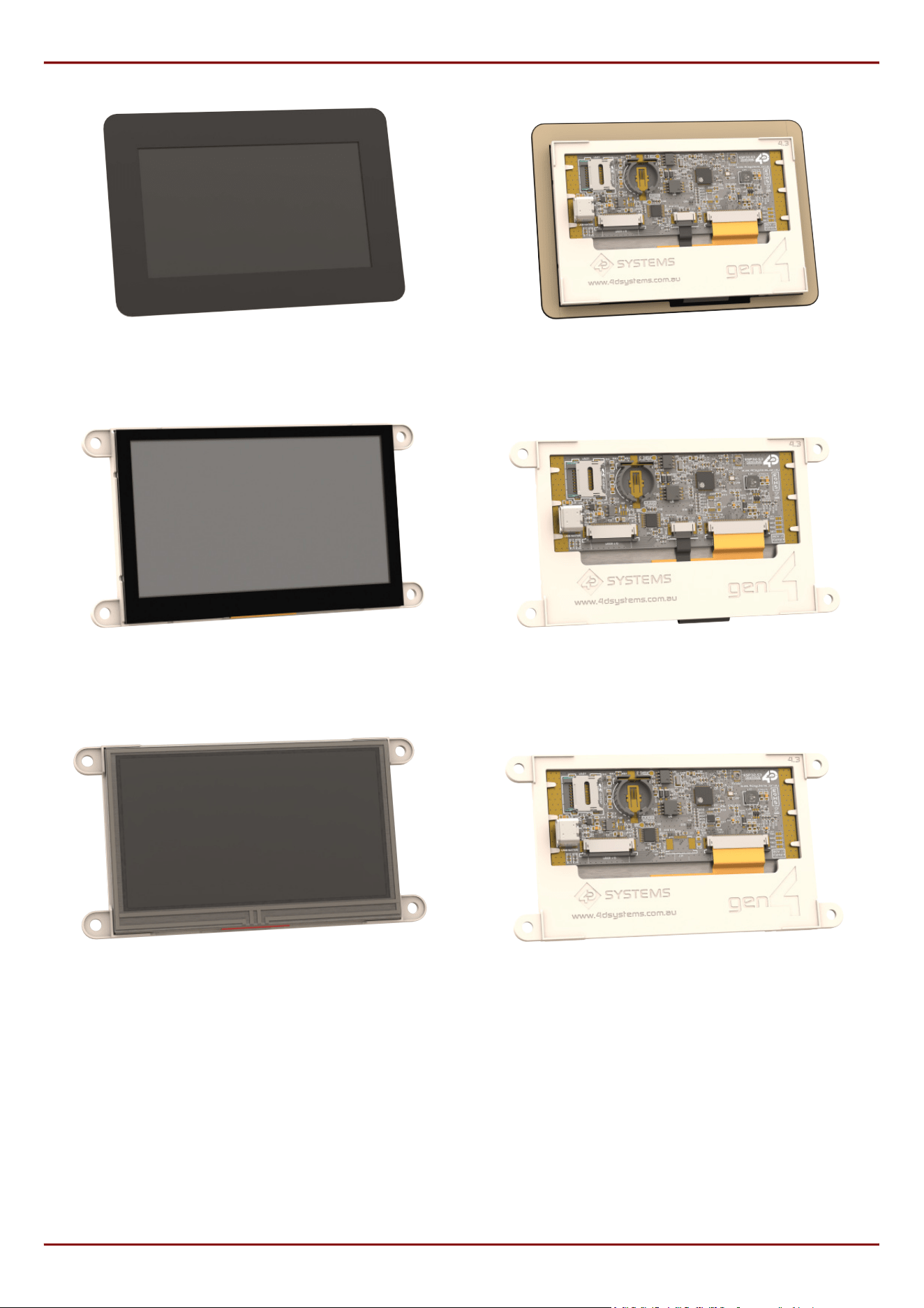
gen4-ESP32-43CT-CLB Front gen4-ESP32-43CT-CLB Rear
gen4-ESP32-43CT Front gen4-ESP32-43CT Rear
gen4-ESP32-43T Front gen4-ESP32-43T Rear
gen4-ESP32-RGB Series Description
4D Systems
DATASHEET
Page 5 of 46

2. Features
Powerful ESP32 Graphics Processor by Espressif.
800x480 resolution displays utilising RGB-565 colours.
IPS TFT LCD display for 4.3" and 5.0" and TN TFT LCD display for 7.0" (WVA available for 7.0").
Available in Non-Touch, Resistive Touch, Capacitive Touch, and Capacitive Touch with Cover Lens Bezel (CLB).
16MB of External Quad SPI Flash.
8MB of Internal Octal SPI PSRAM.
2 native GPIO dedicated to I2C only (As they are used internally on the board) (GPIO17/18).
Up to 17 GPIO of which
Up to 8 GPIO via IO Expander capable of Digital Input/Output (EXT-GPIO0 - EXT-GPIO7).
2 of which are unavailable unless Touch Reset/Interrupt is hardware disabled (EXT-GPIO6/7).
4 native GPIO dedicated to SPI (Shared with microSD card) - CS pin (GPIO38) can be GPIO if SPI not used,
and all 4 SPI pins can be GPIO if microSD card not utilised (GPIO38, GPIO11/12/13).
2 native GPIO dedicated to Native USB-C functionality (GPIO19/20) unless that is hardware disabled, it is
then available as GPIO.
1 native GPIO available after boot (GPIO0), strapping pin.
2 native GPIO available if the UART is not required (GPIO43/44)
Serial UART (GPIO43/44), and up to 3 more UART's available by utilising available GPIO.
On-board Real Time Clock with battery backup (CR1220) - battery not included
30pin FPC connection, for all signals, power, communications, GPIO and UART programming.
Latch-type micro-SD memory card connector for multimedia storage and data logging purposes.
Display full colour images, animations, icons and video clips.
4.0V to 6.0V range operation (single supply).
4x mounting tabs with 4.0mm holes for mechanical mounting using M4 screws (non CLB models only).
3M Adhesive around perimeter of Cover Lens Bezel for mounting the CTP-CLB model.
RoHS and REACH compliant.
CE/EMC and UKCA compliance pending.
PCB is UL 94V-0 Flammability Rated.
•
•
•
•
•
•
•
•
•
•
•
•
•
•
•
•
•
•
•
•
•
•
•
•
•
gen4-ESP32-RGB Series Features
4D Systems
DATASHEET
Page 6 of 46
Module dimensions:
(4.3" non-Touch): 127.6 x 69.3 x 11.8mm
(4.3" Resistive Touch): 127.6 x 69.3 x 12.9mm
(4.3" Capacitive Touch): 127.6 x 69.3 x 13.2mm
(4.3" Capacitive Touch w/ CLB): 123.0 x 84.5 x
13.5mm
(5.0" non-Touch): 142.8 x 77.9 x 11.7mm
(5.0" Resistive Touch): 142.8 x 77.9 x 12.9mm
(5.0" Capacitive Touch): 142.8 x 77.9 x 13.4mm
(5.0" Capacitive Touch w/ CLB): 140.7 x 93.8 x
13.4mm
(7.0" non-Touch): 187.0 x 102.1 x 12.3mm
(7.0" Resistive Touch): 187.0 x 102.1 x 13.4mm
(7.0" Capacitive Touch): 187.0 x 102.1 x 14.0mm
(7.0" Capacitive Touch w/ CLB): 190.1 x 121.9 x
14.0mm
Weighing (approximately):
(4.3" non-Touch): ~ 72g
(4.3" Resistive Touch): ~ 85g
(4.3" Capacitive Touch): ~ 89g
(4.3" Capacitive Touch w/ CLB): ~ 93g
(5.0" non-Touch): ~ 84g
(5.0" Resistive Touch): ~ 102g
(5.0" Capacitive Touch): ~ 107g
(5.0" Capacitive Touch w/ CLB): ~ 112g
(7.0" non-Touch): ~ 176g
(7.0" Resistive Touch): ~ 211g
(7.0" Capacitive Touch): ~ 215g
(7.0" Capacitive Touch w/ CLB): ~ 228g
•
•
•
•
•
•
•
•
•
•
•
•
•
•
•
•
•
•
•
•
•
•
•
•
•
•
The weights and dimensions provided for 7.0" models applies for both WVA and non-WVA variants.
Note
gen4-ESP32-RGB Series Features
4D Systems
DATASHEET
Page 7 of 46
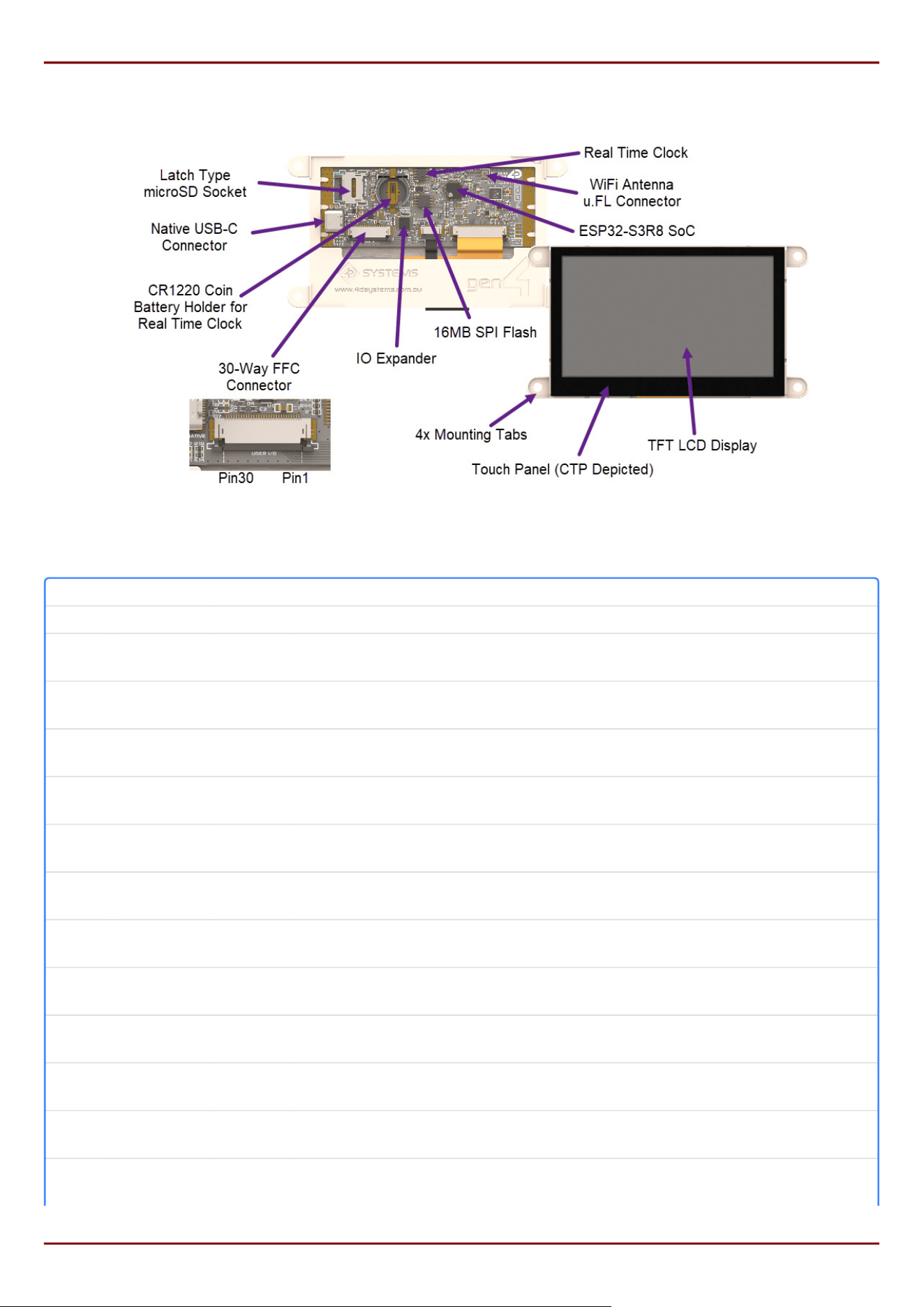
3. Hardware Overview
Hardware Layout (4.3" CTP Module depicted)
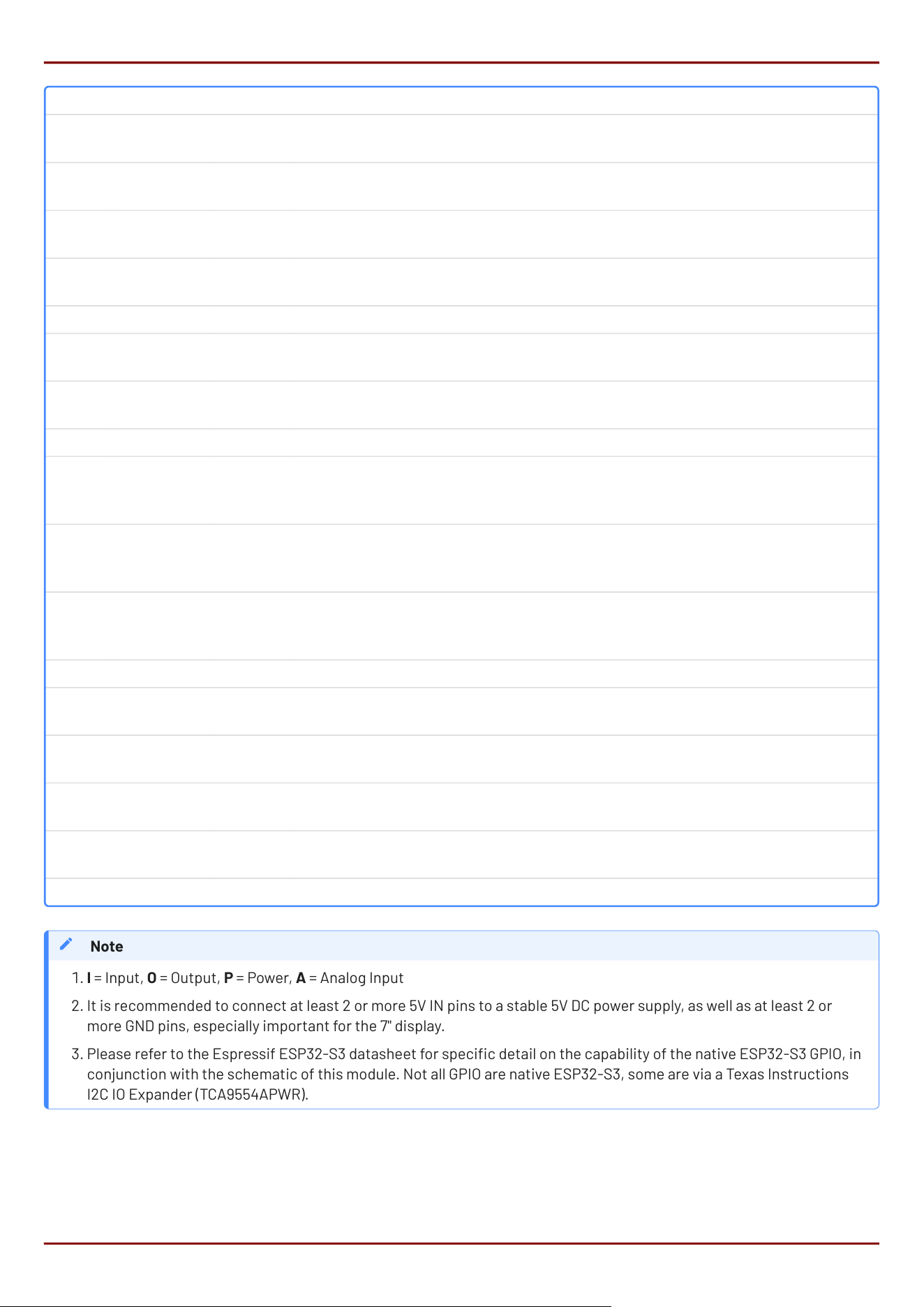
Pin Symbol I/O Description
1 GND P Supply Ground
2
I2C‑SDA
I/O
Dedicated I2C pin as its also used internally, SDA - 3.3V logic. This module is Master
(GPIO17)
3
I2C‑SCL
I/O
Dedicated I2C pin as its also used internally, SCL - 3.3V logic. This module is Master
(GPIO18)
4
EXT‑GPIO0
I/O
General Purpose I/O pin via IO Expender (Digital Input/Output only). This pin has 3.3V
logic and is 5V tolerant for Input
5
EXT‑GPIO1
I/O
General Purpose I/O pin via IO Expender (Digital Input/Output only). This pin has 3.3V
logic and is 5V tolerant for Input
6
EXT‑GPIO2
I/O
General Purpose I/O pin via IO Expender (Digital Input/Output only). This pin has 3.3V
logic and is 5V tolerant for Input
7
EXT‑GPIO3
I/O
General Purpose I/O pin via IO Expender (Digital Input/Output only). This pin has 3.3V
logic and is 5V tolerant for Input
8
EXT‑GPIO4
I/O
General Purpose I/O pin via IO Expender (Digital Input/Output only). This pin has 3.3V
logic and is 5V tolerant for Input
9
EXT‑GPIO5
I/O
General Purpose I/O pin via IO Expender (Digital Input/Output only). This pin has 3.3V
logic and is 5V tolerant for Input
10
EXT‑GPIO6*
I/O
N/C unless hardware mod, then General Purpose I/O pin via IO Expender (Digital
Input/Output only). This pin has 3.3V logic and is 5V tolerant for Input
11
EXT‑GPIO7*
I/O
N/C unless hardware mod, then General Purpose I/O pin via IO Expender (Digital
Input/Output only). This pin has 3.3V logic and is 5V tolerant for Input
12
GPIO38/
SPI‑CS
I/O General Purpose Input/Output, SPI CS capable if using SPI Bus. 3.3V Logic.
13
GPIO11/
SPI‑MOSI
I/O/A
SPI‑MOSI (shared with uSD card) however if uSD not required this can be a General
Purpose Input/Output capable of Analog, 3.3V logic
gen4-ESP32-RGB Series Hardware Overview
4D Systems
DATASHEET
Page 8 of 46
Pin Symbol I/O Description
14
GPIO12/
SPI‑SCLK
I/O/A
SPI‑SCLK (shared with uSD card) however if uSD not required this can be a General
Purpose Input/Output capable of Analog, 3.3V logic
15
GPIO13/
SPI‑MISO
I/O/A
SPI‑MISO (shared with uSD card) however if uSD not required this can be a General
Purpose Input/Output capable of Analog, 3.3V logic
16 GPIO20* I/O/A
N/C unless hardware mod, then General Purpose Input/Output pin capable of Analog,
3.3V logic
17 GPIO19* I/O/A
N/C unless hardware mod, then General Purpose Input/Output pin capable of Analog,
3.3V logic
18 NC - Not Connected
19 GPIO0 I/O
Available after boot, GPIO0 is used for Programming and Boot Strapping. General
Purpose Input/Output, 3.3V logic
20 3.3V P
3.3V Output for User, connected to system 3.3V bus. Excessive draw will affect
system stability. 100mA-200mA draw is OK
21 GND P Supply Ground
22 EN-RST I
Master Reset/Enable signal. Internally pulled up to 3.3V via a 10K resistor. Low will
disable the chip, High will activate the chip. Used by a UART programmer for
programming sequence.
23 U0RXD I
Asynchronous Serial Receive pin, 3.3V TTL level. Connect this pin to the Transmit (Tx)
signal of other serial devices. Used in conjunction with the U0TXD pin for UART
programming or communications. This pin is 3.3V Logic only. (GPIO44)
24 U0TX0 O
Asynchronous Serial Transmit pin, 3.3V TTL level. Connect this pin to the Receive (Rx)
signal of other serial devices. Used in conjunction with the U0RXD pin for UART
programming or communications. This pin is 3.3V Logic only. (GPIO43)
25 GND P Supply Ground
26 5V IN P
Main Voltage Supply +ve input pin. Reverse polarity protected. The range is 4.0V to
6.0V, nominal 5.0V.
27 5V IN P
Main Voltage Supply +ve input pin. Reverse polarity protected. The range is 4.0V to
6.0V, nominal 5.0V.
28 5V IN P
Main Voltage Supply +ve input pin. Reverse polarity protected. The range is 4.0V to
6.0V, nominal 5.0V.
29 5V IN P
Main Voltage Supply +ve input pin. Reverse polarity protected. The range is 4.0V to
6.0V, nominal 5.0V.
30 GND P Supply Ground
I = Input, O = Output, P = Power, A = Analog Input
It is recommended to connect at least 2 or more 5V IN pins to a stable 5V DC power supply, as well as at least 2 or
more GND pins, especially important for the 7" display.
Please refer to the Espressif ESP32-S3 datasheet for specic detail on the capability of the native ESP32-S3 GPIO, in
conjunction with the schematic of this module. Not all GPIO are native ESP32-S3, some are via a Texas Instructions
I2C IO Expander (TCA9554APWR).
Note
1.
2.
3.
gen4-ESP32-RGB Series Hardware Overview
4D Systems
DATASHEET
Page 9 of 46

4. Hardware Interface - Pins
This section describes in detail the hardware interface pins of the module.
4.1. Serial Ports - 3.3V TTL
The gen4-ESP32 Series has a single serial UART, which is broken out to the 30-way FFC connector on this module
(Pins 23 and 24, GPIO43/44). The module is capable of turning the available native GPIO into more serial UART's
also, based on the functionality of the ESP32-S3 processor. Please refer to the Espressif ESP32-S3 Datasheet for
more details.
Depending on which on-board peripherals are used, such as the microSD socket, or the native USB-C, up to 3
additional serial UART's could potentially be congured using GPIO38, GPIO11, GPIO12, GPIO13, GPIO20 and GPIO19.
The module can be programmed over UART (rather than native USB-C) utilising the U0RXD/U0TXD pins, in
conjunction with EN-RST and GPIO0. Please refer to the 4D-UPA Programmer, in the Hardware Tools section.
4.2. I2C Port - 3.3V TTL
The gen4-ESP32 Series has 2 dedicated I2C pins (Pins 2 and 3) available on the 30-way FFC connector, due to I2C
being utilised internally for the Touch, Real Time Clock, and IO Expander. These pins can be utilised by the User for
general purpose I2C devices also. The gen4-ESP32 module is Master in terms of the I2C bus, so only Slave I2C
devices can be added. High trac I2C devices may cause issues with on board devices.
4.3. SPI Port - 3.3V TTL
The gen4-ESP32 Series has an SPI Port available to the user, which is shared with the micro-SD connector,
however has a dedicated CS pin for the User to connect a single SPI device. Further SPI devices could be added,
utilising other spare GPIO to serve as additional CS pins.
gen4-ESP32-RGB Series Hardware Interface - Pins
4D Systems
DATASHEET
Page 10 of 46
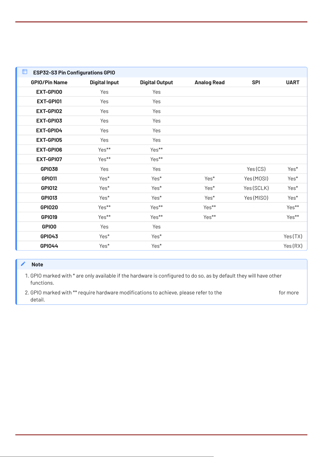
4.4. General Purpose I/O
There are up to 17 general-purpose Input/Output (GPIO) pins available to the user. Some of these GPIO are native to
the ESP32-S3 processor, and some are via an I2C IO Expander.
Please refer to the Espressif ESP32-S3 datasheet for information on how to congure the native GPIO for various
functions, such as Digital-Input/Digital-Output, Analog Input and SPI.
ESP32-S3 Pin Congurations GPIO
GPIO/Pin Name Digital Input Digital Output Analog Read SPI UART
EXT-GPIO0 Yes Yes
EXT-GPIO1 Yes Yes
EXT-GPIO2 Yes Yes
EXT-GPIO3 Yes Yes
EXT-GPIO4 Yes Yes
EXT-GPIO5 Yes Yes
EXT-GPIO6 Yes** Yes**
EXT-GPIO7 Yes** Yes**
GPIO38 Yes Yes Yes (CS) Yes*
GPIO11 Yes* Yes* Yes* Yes (MOSI) Yes*
GPIO12 Yes* Yes* Yes* Yes (SCLK) Yes*
GPIO13 Yes* Yes* Yes* Yes (MISO) Yes*
GPIO20 Yes** Yes** Yes** Yes**
GPIO19 Yes** Yes** Yes** Yes**
GPIO0 Yes Yes
GPIO43 Yes* Yes* Yes (TX)
GPIO44 Yes* Yes* Yes (RX)
GPIO marked with * are only available if the hardware is congured to do so, as by default they will have other
functions.
GPIO marked with ** require hardware modications to achieve, please refer to the Hardware Mods section for more
detail.
Note
1.
2.
gen4-ESP32-RGB Series General Purpose I/O
4D Systems
DATASHEET
Page 11 of 46

EXT-GPIO0
General purpose I/O pin, connected to the ESP32-S3 via an I2C IO Expander. Capable of Digital Input and Output
only. 5V tolerant for input, 3.3V logic level output.
EXT-GPIO1
General purpose I/O pin, connected to the ESP32-S3 via an I2C IO Expander. Capable of Digital Input and Output
only. 5V tolerant for input, 3.3V logic level output.
EXT-GPIO2
General purpose I/O pin, connected to the ESP32-S3 via an I2C IO Expander. Capable of Digital Input and Output
only. 5V tolerant for input, 3.3V logic level output.
EXT-GPIO3
General purpose I/O pin, connected to the ESP32-S3 via an I2C IO Expander. Capable of Digital Input and Output
only. 5V tolerant for input, 3.3V logic level output.
EXT-GPIO4
General purpose I/O pin, connected to the ESP32-S3 via an I2C IO Expander. Capable of Digital Input and Output
only. 5V tolerant for input, 3.3V logic level output.
EXT-GPIO5
General purpose I/O pin, connected to the ESP32-S3 via an I2C IO Expander. Capable of Digital Input and Output
only. 5V tolerant for input, 3.3V logic level output.
EXT-GPIO6
By default, this pin is not available to the User, and is not hardware connected to the 30-way FFC connector. By
default, this pin is used internally to serve the Capacitive Touch INT signal. This can however be congured to
be connected to the 30-way FFC connector if this feature is not required. When modied in hardware (refer to
the Hardware Mods section), this pin is a General purpose I/O pin, connected to the ESP32-S3 via an I2C IO
Expander. Capable of Digital Input and Output only. 5V tolerant for input, 3.3V logic level output.
EXT-GPIO7
By default, this pin is not available to the User, and is not hardware connected to the 30-way FFC connector. By
default, this pin is used internally to serve the Capacitive Touch RESET signal. This can however be congured
to be connected to the 30-way FFC connector if this feature is not required. When modied in hardware (refer
to the Hardware Mods section), this pin is a General purpose I/O pin, connected to the ESP32-S3 via an I2C IO
Expander. Capable of Digital Input and Output only. 5V tolerant for input, 3.3V logic level output.
gen4-ESP32-RGB Series General Purpose I/O
4D Systems
DATASHEET
Page 12 of 46

GPIO38/SPI-CS
This pin is typically used as a CS select pin for the SPI Bus, however can be used as a GPIO pin. It is a native
ESP32-S3 GPIO pin, capable of Digital Input and Output only. It is 3.3V tolerant only and 3.3V logic level.
GPIO11/SPI-MOSI
This pin is shared with the micro-SD connector, and therefore typically must remain as a MOSI SPI pin. Used in
conjunction with the GPIO38/SPI-CS pin, this can be fully utilised by the User as an SPI bus for external devices.
If the micro-SD card is not required and not utilised, this pin can be utilised as a GPIO pin. It is native to the
ESP32-S3 and can be utilised for Digital Input and Output, as well as Analog Input, amongst other native
functionality. This pin is 3.3V tolerant only and 3.3V logic level.
GPIO12/SPI-SCLK
This pin is shared with the micro-SD connector, and therefore typically must remain as a SCLK SPI pin. Used in
conjunction with the GPIO38/SPI-CS pin, this can be fully utilised by the User as an SPI bus for external devices.
If the micro-SD card is not required and not utilised, this pin can be utilised as a GPIO pin. It is native to the
ESP32-S3 and can be utilised for Digital Input and Output, as well as Analog Input, amongst other native
functionality. This pin is 3.3V tolerant only and 3.3V logic level.
GPIO13/SPI-MISO
This pin is shared with the micro-SD connector, and therefore typically must remain as a MISO SPI pin. Used in
conjunction with the GPIO38/SPI-CS pin, this can be fully utilised by the User as an SPI bus for external devices.
If the micro-SD card is not required and not utilised, this pin can be utilised as a GPIO pin. It is native to the
ESP32-S3 and can be utilised for Digital Input and Output, as well as Analog Input, amongst other native
functionality. This pin is 3.3V tolerant only and 3.3V logic level.
GPIO20
By default, this pin is not available to the User, and is not hardware connected to the 30-way FFC connector. By
default, this pin is used by the native USB-C port (USB D+). This can however be congured to be connected to
the 30-way FFC connector if the USB-C port is not required. When modied in hardware (refer to the Hardware
Mods section), this pin is a General Purpose I/O pin native to the ESP32-S3. It is native to the ESP32-S3 and can
be utilised for Digital Input and Output, as well as Analog Input, amongst other native functionality. This pin is
3.3V tolerant only and 3.3V logic level.
gen4-ESP32-RGB Series General Purpose I/O
4D Systems
DATASHEET
Page 13 of 46

GPIO19
By default, this pin is not available to the User, and is not hardware connected to the 30-way FFC connector. By
default, this pin is used by the native USB-C port (USB D-). This can however be congured to be connected to
the 30-way FFC connector if the USB-C port is not required. When modied in hardware (refer to the Hardware
Mods section), this pin is a General Purpose I/O pin native to the ESP32-S3. It is native to the ESP32-S3 and can
be utilised for Digital Input and Output, as well as Analog Input, amongst other native functionality. This pin is
3.3V tolerant only and 3.3V logic level.
GPIO0
Available after boot, GPIO0 is used for Programming via UART and for Boot Strapping. It is a native ESP32-S3
GPIO pin, capable of Digital Input and Output only. It is 3.3V tolerant only and 3.3V logic level.
GPIO43
GPIO43 is used typically as the primary UART, TX pin. If a UART is not required on this pin, then it can be used for
GPIO instead. It is a native ESP32-S3 GPIO pin, capable of Digital Input and Output only. It is 3.3V tolerant only
and 3.3V logic level.
GPIO44
GPIO44 is used typically as the primary UART, RX pin. If a UART is not required on this pin, then it can be used for
GPIO instead. It is a native ESP32-S3 GPIO pin, capable of Digital Input and Output only. It is 3.3V tolerant only
and 3.3V logic level.
gen4-ESP32-RGB Series General Purpose I/O
4D Systems
DATASHEET
Page 14 of 46

4.5. System Pins
5V IN (Module Voltage Input):
Module supply voltage input pins. At least two (however ideally four) of these pins should be connected to a
stable supply voltage in the range of 4.0 Volts to 5.5 Volts DC. Nominal operating voltage is 5.0 Volts. Utilising 4
pins shares the current over the FFC cable, which is important for the larger size displays.
GND (Module Ground):
Device ground pins. At least two (ideally four) pins should be connected to the ground.
EN-RST (Module Enable/Disable/Reset):
This pin is connected to a 10K pull-up resistor, which is pulling the module to the enabled state by default.
Pulling this pin to 0V will disable the module, and put it into a reset state. Pulling the pin High or oating (due to
build in pull-up resistor) will enable the module. This pin is utilised when utilising the UART Programming
method.
gen4-ESP32-RGB Series System Pins
4D Systems
DATASHEET
Page 15 of 46

4.6. Accessing Other GPIO Pins - Hardware Mods Required
GPIO19
GPIO19 by default is USB-D-, part of the USB+/USB- combination for the Native USB-C port.
If there is no desire to utilise the onboard USB-C connector, or an external extension is going to be made
utilising the 30-way FFC connector, or the pins are desired to be GPIO, it is possible to achieve with a small
hardware modication. In order to access this pin on the 30-way FFC, a resistor needs to be removed (R13) and
another needs to be added (R8) or a simple solder blob will suce in this position.
If this is going to be a required modication for your end-product, and it will be used in a production application,
it is possible to request 4D Systems to move this by default when you order the product. Please contact our
Sales team with your requirements.
GPIO20
GPIO20 by default is USB-D+, part of the USB+/USB- combination for the Native USB-C port.
If there is no desire to utilise the onboard USB-C connector, or an external extension is going to be made
utilising the 30-way FFC connector, or the pins are desired to be GPIO, it is possible to achieve with a small
hardware modication. In order to access this pin on the 30-way FFC, a resistor needs to be removed (R12) and
another needs to be added (R9) or a simple solder blob will suce in this position.
If this is going to be a required modication for your end-product, and it will be used in a production application,
it is possible to request 4D Systems to move this by default when you order the product. Please contact our
Sales team with your requirements.
EXT-GPIO6
EXT-GPIO6 is one of the GPIO from the IO Expander, and by default is connected to the Touch Panels INT pin.
If there is no requirement for touch (ie you have a non-Touch module), or this pin is required, and you plan on
modifying the code/library to not utilise this pin, it can be redirected to the 30-way FFC by removing resistor
R55, and adding it back into the position of R40 (or simply placing a solder blob).
If this is going to be a required modication for your end-product, and it will be used in a production application,
it is possible to request 4D Systems to move this by default when you order the product. Please contact our
Sales team with your requirements.
gen4-ESP32-RGB Series Accessing Other GPIO Pins - Hardware Mods Required
4D Systems
DATASHEET
Page 16 of 46

EXT-GPIO7
EXT-GPIO7 is one of the GPIO from the IO Expander, and by default is connected to the Touch Panels RESET pin.
If there is no requirement for touch (ie you have a non-Touch module), or this pin is required, and you plan on
modifying the code/library to not utilise this pin, it can be redirected to the 30-way FFC by removing resistor
R56, and adding it back into the position of R41 (or simply placing a solder blob).
If this is going to be a required modication for your end-product, and it will be used in a production application,
it is possible to request 4D Systems to move this by default when you order the product. Please contact our
Sales team with your requirements.
gen4-ESP32-RGB Series Accessing Other GPIO Pins - Hardware Mods Required
4D Systems
DATASHEET
Page 17 of 46

5. Module Features
The gen4-ESP32 Series is designed to accommodate a wide variety of applications. Some of the main features of
the module are listed below.
5.1. ESP32-S3R8 Processor
The module is designed around the ESP32-S3R8 Processor from Espressif. This model of ESP32-S3 has 8MB of
build in Octal SPI PSRAM, and utilises External Quad SPI Flash for application storage. Media is typically stored on
a micro-SD card, however some types of media can be stored in SPI Flash, but it is very limited for capacity.
A majority of the ESP32-S3's GPIO pins are utilised for driving the RGB display, so this module features a Texas
Instruments I2C IO Expander to provide 8 additional GPIO, 2 of which are used internally and the rest are available
for the User.
5.2. Chipsets used
The gen4-ESP32 Series of modules utilises a few chipsets from various manufacturers, in order for these modules
to operate. Please refer to the Schematic for connection details.
The main processor is an Espressif ESP32-S3R8, as mentioned in the previous section.
The backlight is controlled using an ETA Solutions ETA1611S2G backlight driver, which takes On/Off/PWM input
from the ESP32-S3 using GPIO2.
For Capacitive Touch models, the chipset for the capacitive touch is I2C driven, and the chipset is found on the
Display ex itself. These utilise Focaltech FT5446 controllers for 4.3", 5.0" and 7.0" models.
For Resistive Touch models, the chipset used is the NSIWAY NS2009 Resistive Touch driver, which is a 4-wire
controller, and is I2C driven.
The Real Time Clock utilises the NXP PCF8563T/5 real time clock, which is also I2C driven. This is battery
backed up with a CR1220 coin cell battery. Battery is not included.
The IO Expander which provides 8 additional GPIO to the module, is the Texas Instruments TCA9554APWR
controller, which is I2C driven.
The Quad SPI Flash memory used on these modules, is the Giga-Devices GD25Q127C, which is 16MB in capacity,
and interfaces to the ESP32-S3 on the same Octal/Quad SPI bus as the PSRAM which is built into the ESP32-
S3R8 chipset itself.
The micro-SD card interface, while not a chipset, is still worthy of note. It utilises a dedicated 1-bit SPI bus from
the ESP32-S3, which can be shared with the User if required. The micro-SD cards used must be SPI compatible
due to the interface type - more detail below.
•
•
•
•
•
•
•
•
gen4-ESP32-RGB Series Module Features
4D Systems
DATASHEET
Page 18 of 46
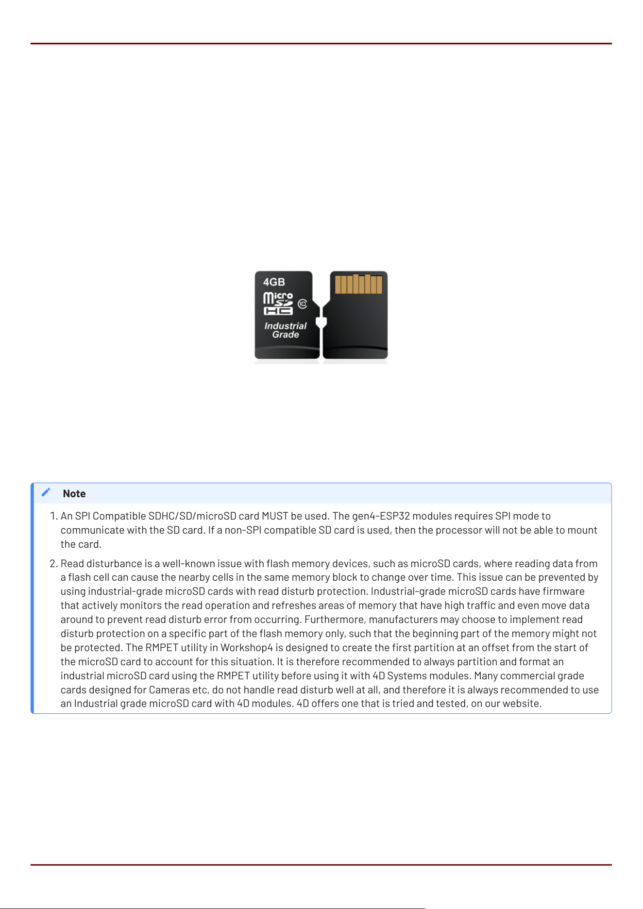
5.3. SD/SDHC Memory Cards
The gen4-ESP32 modules use off-the-shelf standard SDHC/SD/microSD memory cards with up to 4GB capacity
usable with FAT16 formatting, and much higher with FAT32 formatting. For any FAT le-related operations, before
the memory card can be used it must rst be formatted. The formatting of the card can be done on any PC system
with a card reader.
Cards with a FAT16 formatting (4GB or under partition) are capable of operating faster on this display module,
compared to the same card (16GB for example) with a single FAT32 partition, due to the nature of FAT16 vs FAT32
le transfers. If your application media can t inside a 4GB partition, it is recommended to use FAT16 to gain the
maximal speed possible.
RMPET, a 4D Systems Tool found in the Workshop4 IDE, is capable of repartitioning and formatting microSD cards
for FAT16, to be the appropriate type and format. This tool should be used for all cards as it also employs an offset
which is critical when using Industrial microSD cards which feature Read Disturb Prevention rmware, which is a
special rmware inside the microSD card designed to prevent Read Disturb occurring on NAND based Flash
media. Further discussed in the note.
An SPI Compatible SDHC/SD/microSD card MUST be used. The gen4-ESP32 modules requires SPI mode to
communicate with the SD card. If a non-SPI compatible SD card is used, then the processor will not be able to mount
the card.
Read disturbance is a well-known issue with ash memory devices, such as microSD cards, where reading data from
a ash cell can cause the nearby cells in the same memory block to change over time. This issue can be prevented by
using industrial-grade microSD cards with read disturb protection. Industrial-grade microSD cards have rmware
that actively monitors the read operation and refreshes areas of memory that have high trac and even move data
around to prevent read disturb error from occurring. Furthermore, manufacturers may choose to implement read
disturb protection on a specic part of the ash memory only, such that the beginning part of the memory might not
be protected. The RMPET utility in Workshop4 is designed to create the rst partition at an offset from the start of
the microSD card to account for this situation. It is therefore recommended to always partition and format an
industrial microSD card using the RMPET utility before using it with 4D Systems modules. Many commercial grade
cards designed for Cameras etc, do not handle read disturb well at all, and therefore it is always recommended to use
an Industrial grade microSD card with 4D modules. 4D offers one that is tried and tested, on our website.
Note
1.
2.
gen4-ESP32-RGB Series SD/SDHC Memory Cards
4D Systems
DATASHEET
Page 19 of 46
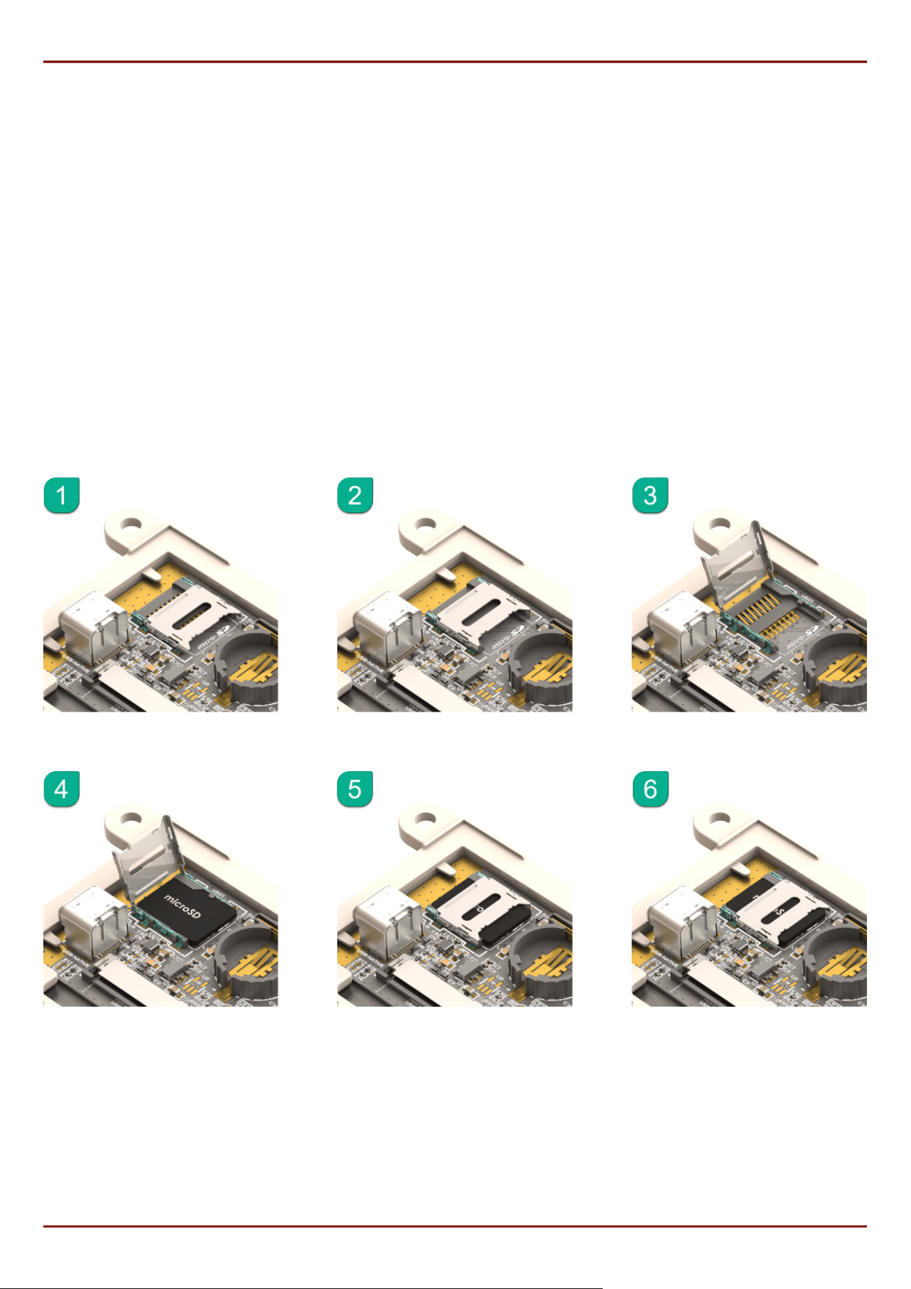
5.4. microSD Socket Usage
On the gen4-ESP32 modules is a Latch-Type microSD socket. To use this socket is simple if you follow these easy
steps.
Unlock the empty socket by sliding/unlocking the socket towards the edge of the PCB (away from the battery
holder).
Lifting the lid of the socket, and hinging it up off the PCB, towards the edge of the module.
Placing a microSD card into the socket.
Lowering the lid of the socket back down, by hinging it down towards the PCB again.
Locking the socket back in place by sliding/locking the socket towards the battery holder.
Please refer to the following diagram for guidance:
•
•
•
•
•
gen4-ESP32-RGB Series microSD Socket Usage
4D Systems
DATASHEET
Page 20 of 46

5.5. FAT16 vs FAT32
FAT16 is capable of having a partition with up to 4GB capacity usable. While this might seem like a limitation, it still
offers the best performance for small processor systems such as the ESP32-S3. Larger partitions are possible
with FAT32 formatting, however smaller cluster size results, giving slightly worse performance.
For any FAT le-related operations, before the memory card can be used it must rst be formatted correctly. Built
into Workshop4 is a tool created by 4D, called RMPET (please refer to the Tools menu, in any Environment, inside
the Workshop4 IDE). RMPET allows the User to easily partition and format microSD cards, to make their le system
ready to be used with 4D Systems modules. The formatting of the card can be done on any Windows PC system
with a card reader.
5.6. Wide Viewing Angle (WVA)
The 7.0" model in this gen4 series has the option to use a WVA-type display, rather than the standard TN display.
While WVA is physically still a TN display, it features much wider viewing angles and prevents image inversion
when viewing at steep viewing angles. The outcome is a similar effect and visual improvement to an IPS display,
while still using a cost-effective TN display technology. Many applications can benet from wider viewing angles.
gen4-ESP32-RGB Series FAT16 vs FAT32
4D Systems
DATASHEET
Page 21 of 46

6. Display/Module Precautions
Avoid having to display the same image/object on the screen for lengthy periods. This can cause a burn-in
which is a common problem with all types of display technologies. Blank the screen after a while or dim it very
low by adjusting the contrast. Better still; implement a screen saver feature.
Moisture and water can damage the display. Moisture on the surface of a powered display should not cause any
problems, however, if water is to enter the display either from the front or from the rear, or come in contact
with the PCB, it will damage. Wipe off any moisture gently or let the display dry before usage. If using this
display module in an environment where it can get wet, ensure an appropriate enclosure is used.
Dirt from ngerprint oil and fat can easily stain the surface of the display. Gently wipe off any stains with a soft
lint-free cloth.
The performance of the display will degrade under high temperatures and humidity. Avoid such conditions
when storing.
Do not tamper with the display ex cable that is connected to the control board. This may affect the connection
between the display and the driving circuitry and cause failure.
Displays are susceptible to mechanical shock and any force exerted on the module may result in deformed
zebra stripes, a cracked display cell and a broken backlight.
Always use the mounting holes on the module's to mount the display where possible, or mount using the CLB for
CLB based modules.
Display modules have a nite life, which is typically dictated by the display itself, more specically the
backlight. The backlight contains LEDs, which fade over time. In the Specications section is a gure for the
typical life of the display, and the criteria are listed.
The resistive Touch model features a touch-sensitive lm over the display which is sensitive to pressure. When
mounting the display module in an enclosure, you should not apply pressure to the surface of the display by the
enclosure. It could result in false touches or the touch will simply not function at all.
•
•
•
•
•
•
•
•
•
gen4-ESP32-RGB Series Display/Module Precautions
4D Systems
DATASHEET
Page 22 of 46
7. Hardware Tools
The following hardware tools are required for full control of the gen4-ESP32 Display Modules.
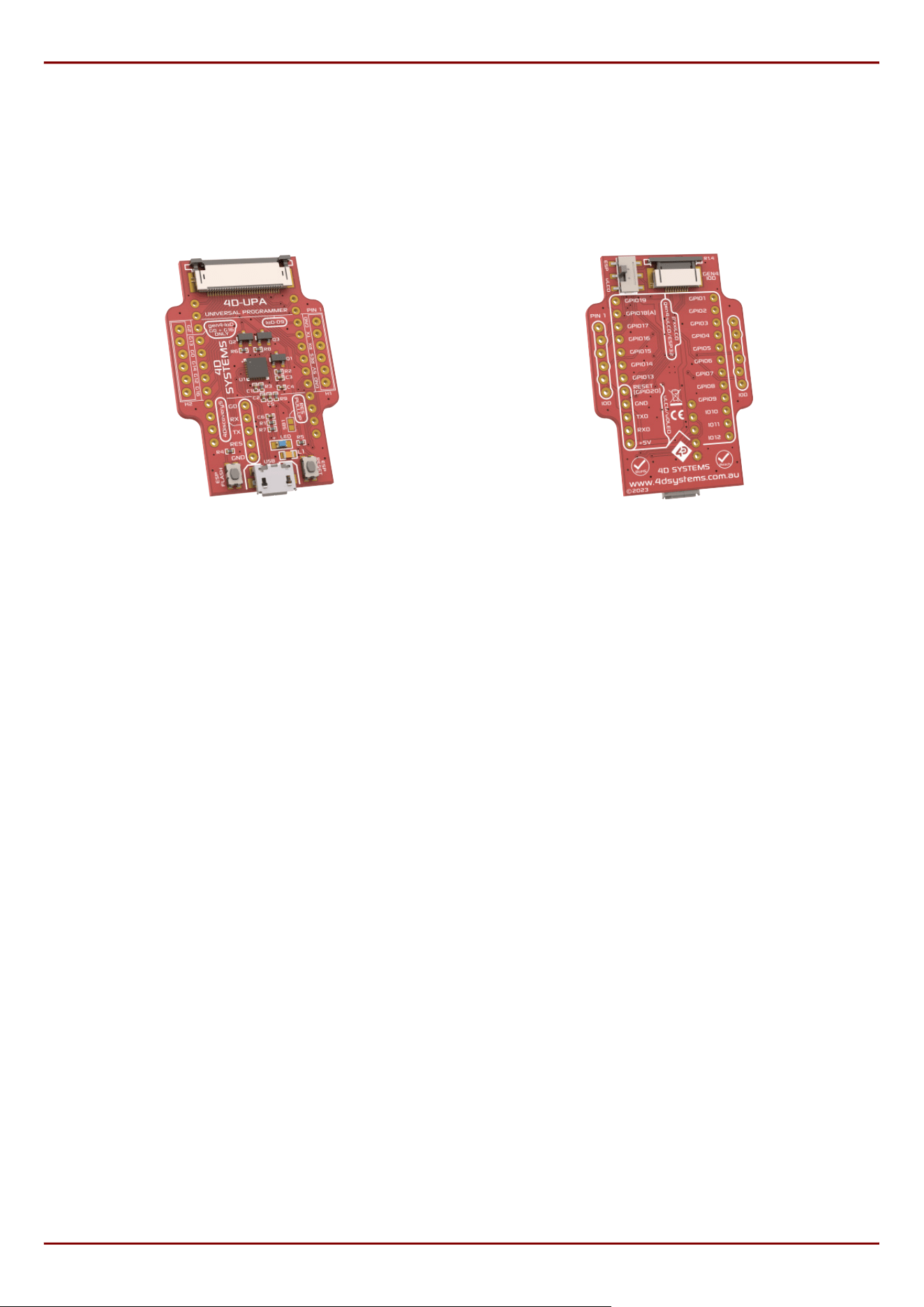
7.1. 4D-UPA
4D-UPA Front 4D-UPA Back
The 4D-UPA minimizes the connections and modules required for programming the gen4-ESP32 series via its
UART - creating a single module with a micro USB interface, and DIP style pads for GPIO breakout of all the signals
used on the gen4 Display interface, which is useful for development or nal product use.
The GPIO naming convention on the 4D-UPA does not reect the GPIO naming of the actual display module, due to
the 4D-UPA being universal and able to be used with many 4D Products. Please review the 4D-UPA datasheet for
information on mapping the GPIO naming from this module, with the GPIO naming on the 4D-UPA, to ensure you
connect to the correct pins you desire.
Typically, a 4D-UPA should not be required for programming the gen4-ESP32 series of modules, as they have USB-
C on board, however if problems occur or situations arise that the USB-C is non-functional, then the 4D-UPA
would be required, so it is a good tool to have on hand.
gen4-ESP32-RGB Series Hardware Tools
4D Systems
DATASHEET
Page 23 of 46
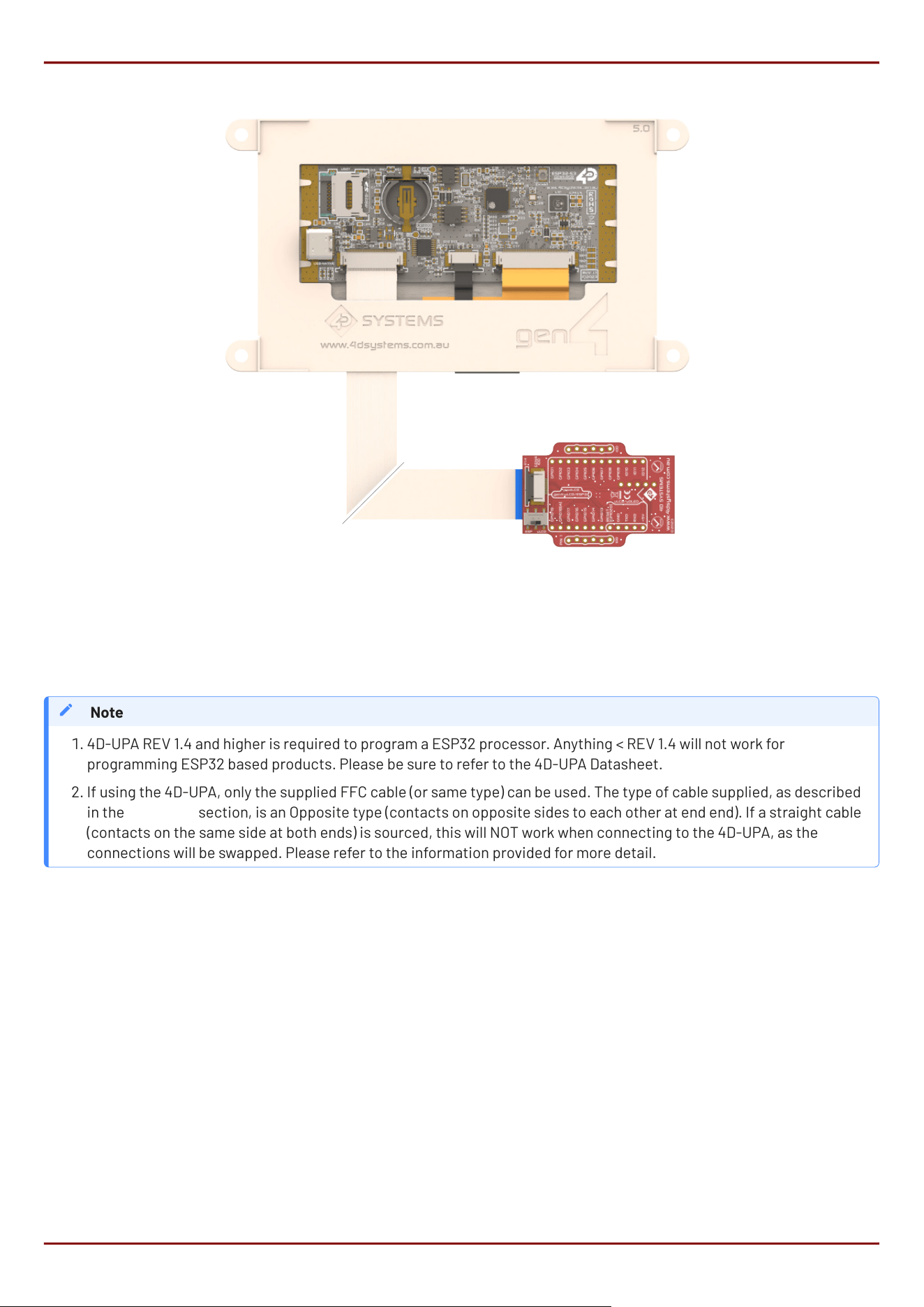
The 4D-UPA is connected to the ESP32 module using the supplied 30-way FFC Cable. The connectors on both the
ESP32 module, and the 4D-UPA, are Top-Contact, meaning the FFC cable pins should be facing upwards, and the
blue stiffener, should be facing down towards the PCB.
4D-UPA REV 1.4 and higher is required to program a ESP32 processor. Anything < REV 1.4 will not work for
programming ESP32 based products. Please be sure to refer to the 4D-UPA Datasheet.
If using the 4D-UPA, only the supplied FFC cable (or same type) can be used. The type of cable supplied, as described
in the FFC Cable section, is an Opposite type (contacts on opposite sides to each other at end end). If a straight cable
(contacts on the same side at both ends) is sourced, this will NOT work when connecting to the 4D-UPA, as the
connections will be swapped. Please refer to the information provided for more detail.
Note
1.
2.
gen4-ESP32-RGB Series 4D-UPA
4D Systems
DATASHEET
Page 24 of 46
7.2. USB-C Cable
A USB-C Cable is the primary way to program a gen4-ESP32 module from 4D Systems, aside from using a 4D-UPA,
as described previously.
A USB-C cable is not supplied with the modules, as they can be sourced from any computer or hardware store, and
come with most Cell Phones these days too.
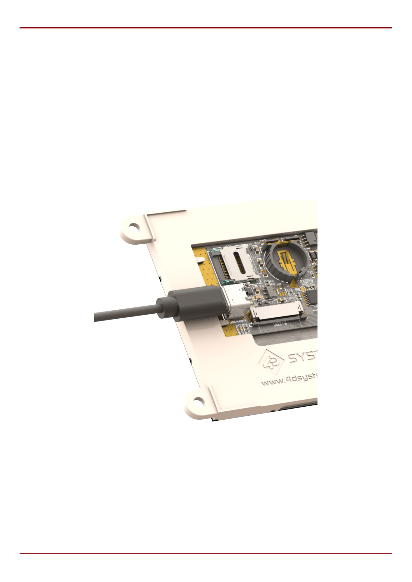
Connection of the USB-C cable to the module is simple, and simply plugs into the USB-C connector on the board,
clearing the gen4 plastics on the side.
The USB-C provides power as well as USB Data communications, for while developing software on the module and
programming it. The USB-C cable can be used in the end product use if desired, or the use of the FFC-Cable
directly to the projects main Application PCB as an alternative.
USB-C Connection
gen4-ESP32-RGB Series USB-C Cable
4D Systems
DATASHEET
Page 25 of 46
8. Software Tools
8.1. Workshop4 IDE
Workshop4 is a comprehensive software IDE that provides an integrated software development platform for all
the 4D family of processors and modules, as well as some 3rd party processors such as the Espressif ESP32.
The IDE provides an Editor and WYSIWYG design area for gen4-ESP32 based modules, to develop complete
application code with various widgets and media references as required. All user application code is developed
within the Workshop4 IDE, and is easily coupled with graphics and media, so is a one-stop shop for development
with these modules.
The Workshop4 IDE utilises the Arduino IDE 2.x CLI to handle the compiling, linking and downloading of ESP32
based projects, using the ESP32 Arduino Core and associated libraries, without having to interface with the
Arduino IDE at all.
When using Workshop4, the library GFX4dESP32 is used. This library maintains compatibility with gen4-IoD
(ESP8266) series, through the library GFX4d. This means that older gen4-IoD projects can be easily converted to
this product line, with minimal to no modications, as long as the hardware supports all functionality.
Arduino IDE 2.x and Arduino CLI are not included when installing Workshop4 and must be installed separately.
For complete development setup instructions, please refer to the Workshop4 ESP32 Development Manual.
Note
gen4-ESP32-RGB Series Software Tools
4D Systems
DATASHEET
Page 26 of 46
8.2. Workshop5 IDE
Workshop5 is the new IDE from 4D Systems, which will eventually take over Workshop4 when it is fully developed.
It is still in development, however can be actively used for new applications for many of the 4D Systems modules,
including the ESP32-S3 modules. It is a comprehensive software IDE that provides an integrated software
development platform for all the 4D family of processors and modules, as well as some 3rd party processors such
as the Espressif ESP32, and the Raspberry Pi RP2350 modules.
The IDE provides an Editor and WYSIWYG design area for ESP32-S3 based modules, to develop complete
application code with various widgets and media references as required. All user application code is developed
within the Workshop5 IDE, and is easily coupled with graphics and media, so is a one stop shop for development
with these modules.
The Workshop5 IDE utilises the Arduino IDE 2.x CLI to handle the compiling, linking and downloading of ESP32
based projects, using the Arduino-ESP32 Core and associated libraries, without having to interface with the
Arduino IDE at all.
When using Workshop5, the library Graphics4D is used. This library maintains compatibility with other Workshop5
compatible products that are programed in C++, such as the 4D Systems' RP2350B products. This means that C++
graphics code used in Workshop5 project can be easily used to this product line, with minimal to no modications.
Arduino IDE 2.x and Arduino CLI are included when installing Workshop5, so there is no need to installed these separately.
For complete development setup instructions, please refer to the Workshop5 ESP32 Development Manual.
Note
gen4-ESP32-RGB Series Workshop5 IDE
4D Systems
DATASHEET
Page 27 of 46

8.3. Workshop Built-in Tools
Built into Workshop4 and Workshop5 are a number of tools which are available to aid the programming of the
ESP32-S3 series of displays.
Terminal, as the name implies, is a terminal application that can be used to communicate with the display module
and is primarily used for basic debugging. It displays incoming Serial messages from the display module in ASCII
and HEX format. It is capable of sending character or hex strings as well as keystrokes to the display.
RMPET is a partitioning and formatting tool, used to correctly set up a micro-SD card for use with 4D Systems
products. This is further discussed in the SD/SDHC Memory Cards section
9. Programming Language
The programming language used in the Workshop4 and Workshop5 IDEs to program the gen4-ESP32 series of
modules, is C++, which is the same as native Arduino IDE written code.
The Arduino programming language is a user-friendly coding system tailored for Arduino microcontrollers. It
simplies microcontroller coding, bridging the gap between users and hardware. Its approachability and
community support make it ideal for various projects.
gen4-ESP32-RGB Series Workshop Built-in Tools
4D Systems
DATASHEET
Page 28 of 46
10. ESP-IDF Development
While it's recommended to use Workshop4 or Workshop5 IDEs to create applications for these displays, having
ESP32-S3 at its core allows any user to develop applications directly through the ocial development framework
from Espressif.
When using ESP-IDF, users can utilise search and utilize various IDF components by searching through the ESP
Component Registry. These serves as libraries simplifying development similar to Arduino. However, these are
mostly written in C rather than C++.
To aid with setting up our ESP32-S3 RGB displays for ESP-IDF development, here are some recommended
components for this product line:
Peripheral Component
LCD
No external component required.
Refer to RGB Interfaced LCD in Espressif Docs
Capacitive Touch espressif/esp_lcd_touch_ft5x06
Resistive Touch No available component for NS2009 at time of writing
RTC esp-idf-lib/pcf8563
I/O Expander espressif/esp_io_expander_tca9554
For LCD timings, please refer to the 4DLCD datasheets:
4DLCD-43800480 - Please contact 4D Systems support team
4DLCD-50800480
4DLCD-70800480
4DLCD-90800480
Note
•
•
•
•
gen4-ESP32-RGB Series ESP-IDF Development
4D Systems
DATASHEET
Page 29 of 46
11. Display Module Part Numbers
The following is a breakdown of the part numbers and what they mean.
Examples:
gen4-ESP32-43T
gen4-ESP32-50CT
gen4-ESP32-70CT-CLB-WVA
Example Starter Kits
SK-gen4-ESP32-43T
SK-gen4-ESP32-50CT
SK-gen4-ESP32-70CT-CLB-WVA
where:
•
•
•
•
•
•
SK - Starter Kit (kitting of multiple parts)
gen4 - gen4 Display Range
ESP32 - ESP32 Display Family
43 - Display size (4.3")
50 - Display size (5.0")
70 - Display size (7.0")
T - Resistive Touch
CT - Capacitive Touch
CLB - Cover Lens Bezel
WVA - Wide Viewing Angle display (7.0" only)
The SK at the start denotes it’s a Starter Kit, and the rest of the part number describes the display module in the
Starter Kit.
A product without a T or CT in the part number is a non-touch variant.
Cover Lens Bezels (CLB) are glass fronts for the display module with overhanging edges, which allow the display
module to be mounted directly into a panel using special adhesive on the overhanging glass. This is available for
capacitive touch only.
Resistive Touch models are not available in CLB, as a CLB is made of glass and resistive touch relies on the
mechanical exing of a membrane to trigger touch.
WVA stands for Wide Viewing Angle and is a special and optional addition to the 7" range of modules, which boosts
viewing angles of the display and prevents image inversion when viewing at steep viewing angles. The outcome is a
similar effect and visual improvement to an IPS display, however, it uses a TN display. This is only an option for the 7".
WVA models are the same physical dimensions as a regular 7".
Note
•
•
•
•
•
gen4-ESP32-RGB Series Display Module Part Numbers
4D Systems
DATASHEET
Page 30 of 46
12. Cover Lens Bezel - Tape Spec
The perimeter of the CLB display modules features double-sided adhesive tape, designed to stick directly onto a
panel, enclosure, box etc. without the need for any mounting screws or hardware.
The tape used is 3M 9495LE tape, which uses well-known and strong 3M 300LSE adhesives. The double-sided
adhesive has a thickness of 0.175mm once the backing has been removed.
More information on this adhesive can be found on the 3M website.
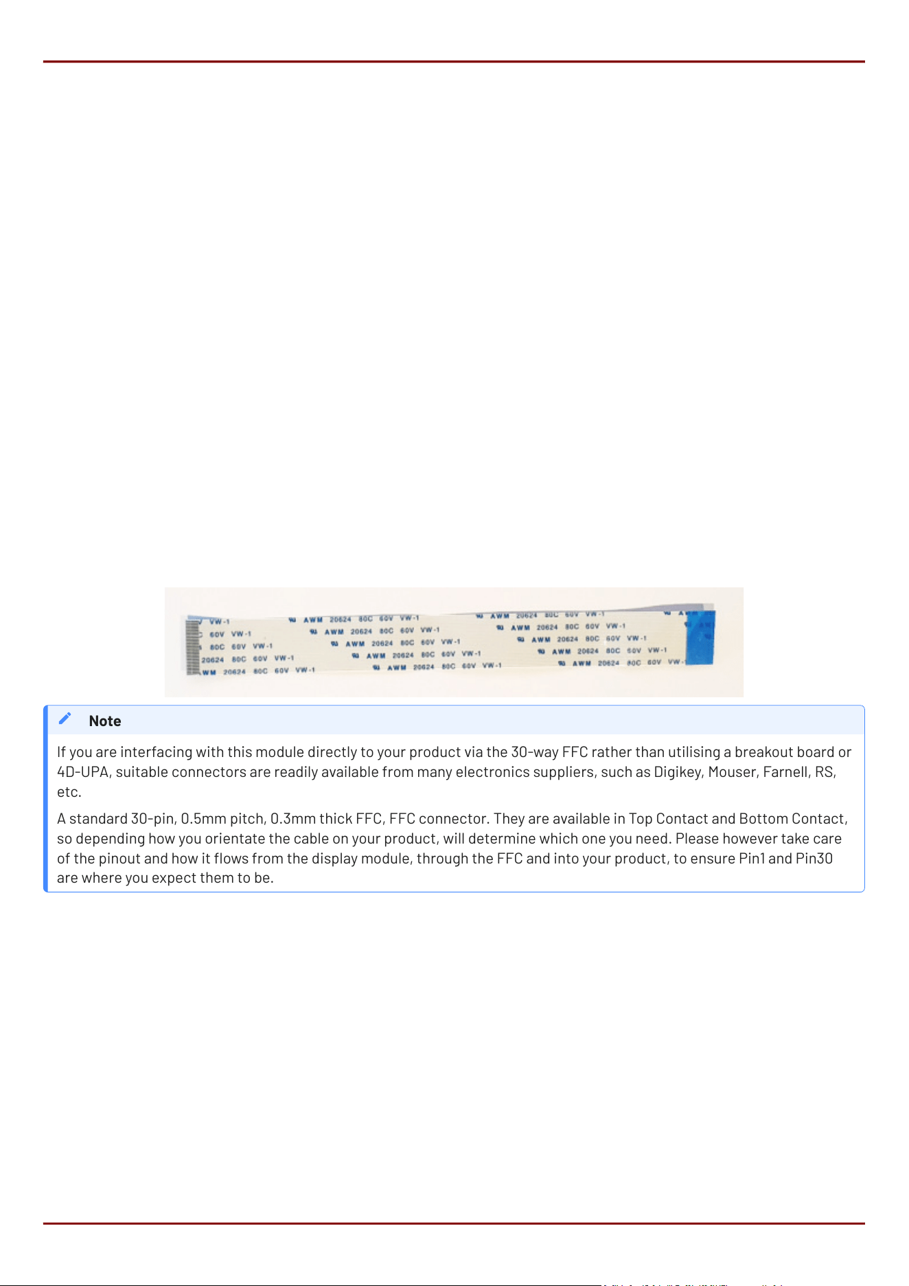
13. FFC Cable
The FFC cables supplied by 4D Systems (included with products) have the following specications:
30 Pin Flexible Flat Cable, 150mm Long, 0.5mm (0.02") pitch
Cable Type: AWM 20624 80C 60V VW-1
Heat Resistance 80 Degrees Celsius
Connections on the opposite side at each end (Type B)
You can get different cable lengths from the 4D Systems website.
•
•
•
•
If you are interfacing with this module directly to your product via the 30-way FFC rather than utilising a breakout board or
4D-UPA, suitable connectors are readily available from many electronics suppliers, such as Digikey, Mouser, Farnell, RS,
etc.
A standard 30-pin, 0.5mm pitch, 0.3mm thick FFC, FFC connector. They are available in Top Contact and Bottom Contact,
so depending how you orientate the cable on your product, will determine which one you need. Please however take care
of the pinout and how it ows from the display module, through the FFC and into your product, to ensure Pin1 and Pin30
are where you expect them to be.
Note
gen4-ESP32-RGB Series Cover Lens Bezel - Tape Spec
4D Systems
DATASHEET
Page 31 of 46
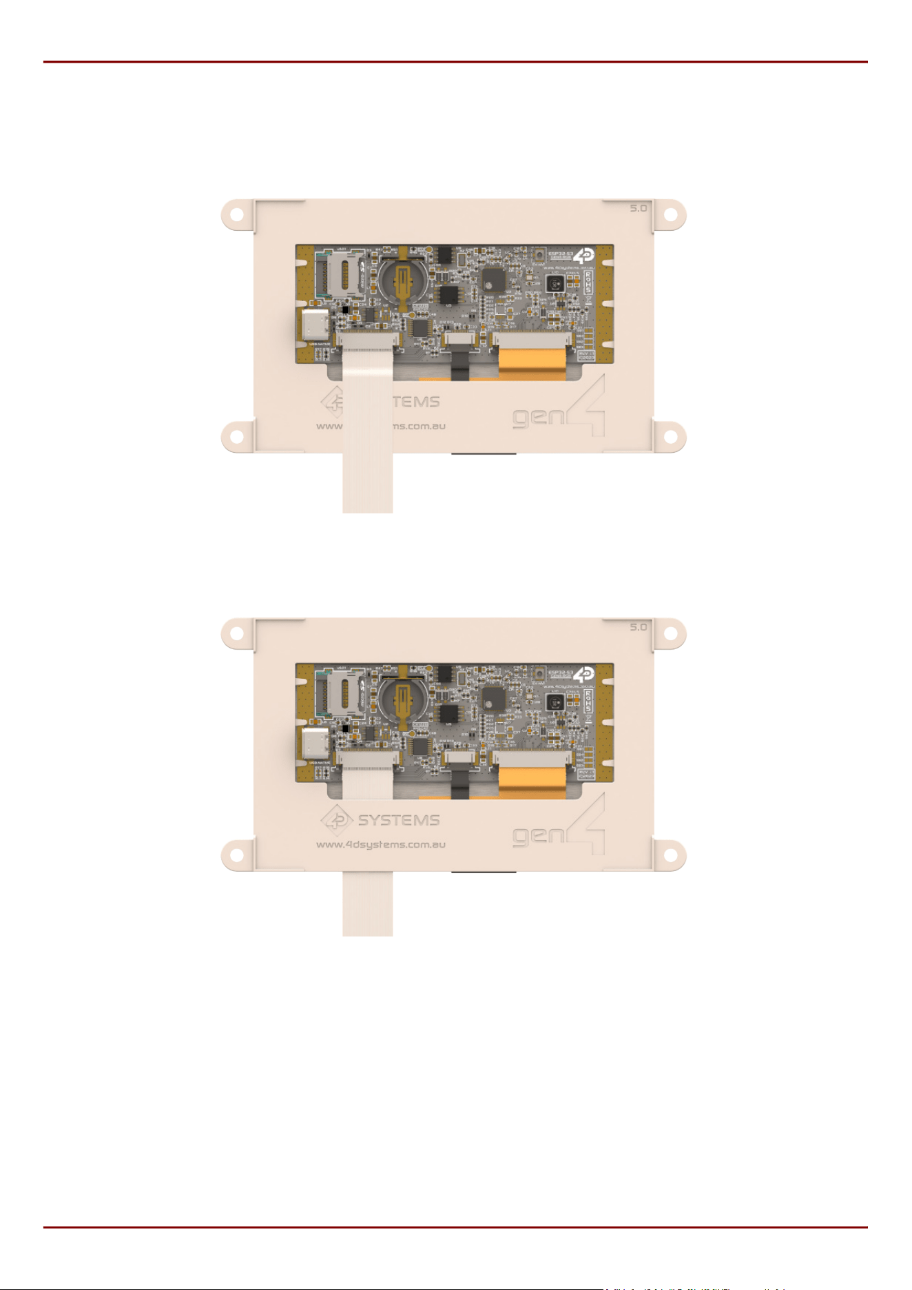
The ESP32 modules are designed with gen4 plastics and the FFC cable can either be connected and sit above the
plastics, or can thread underneath and out the bottom.
FFC Cable - Over Plastics
FFC Cable - Under Plastics
gen4-ESP32-RGB Series FFC Cable
4D Systems
DATASHEET
Page 32 of 46

14. Starter Kit
4D Systems highly recommends all rst-time buyers of 4D Systems’ displays, to purchase the Starter Kit when
purchasing their rst 4D Systems display solution.
The Starter Kit provides all the hardware that is required to get the User up and running.
Starter Kits typically include:
gen4 ESP32 Display Module
gen4 Breakout Board (gen4-Breakout)
4D Universal Programming Adaptor (4D-UPA REV1.4 or higher)
4GB micro-SD Card
150mm 30-way FFC cable for connecting display to gen4-Breakout, 4D-UPA, or Users System
Wi-Fi Antenna (u.FL to SMA, and screw on SMA antenna)
Please refer to the 4D Systems website for the current components included in the Starter Kit.
Simply select the Starter Kit option when purchasing the chosen display module on the 4D Systems shopping cart,
or from your local distributor.
•
•
•
•
•
•
gen4-ESP32-RGB Series Starter Kit
4D Systems
DATASHEET
Page 33 of 46

19. Specifications
Absolute Maximum Ratings
Operating ambient temperature -20°C to +65°C (see note 1 and 2)
Storage temperature -30°C to +80°C
Voltage on any digital input pin (ESP32) with respect to GND -0.3V to 3.6V
Voltage on any digital input pin (IO Expander) with respect to GND -0.3V to 6.0V
Voltage on VCC with respect to GND -0.3V to 6.5V
Quote Espressif
"Ambient temperature species the recommended temperature range of the environment immediately outside an
Espressif chip. For ESP32-S3R8 if the PSRAM ECC function is enabled, the maximum ambient temperature can be
improved to 85°C, while the usable size of PSRAM will be reduced by 1/16".
Temperature range for Ambient and Storage, are determined by a combination of components used on these
modules. While some components may be capable of exceeding these temperatures, some are not, so the
minimums/maximums are determined by the weakest device on the modules. Based on the 65°C/85°C note above, if
the ESP32-S3R8 is increased to 85°C capability, the next 'weakest' component on the module is the TFT LCD, which is
capable of -20°C to 70°C Operating Temp.
Stresses above those listed here may cause permanent damage to the device. This is for stress rating only and
functional operation of the device at those or any other conditions above those indicated in the recommended
operation listings of this specication is not implied. Exposure to maximum rating conditions for extended periods
may affect device reliability.
Note
1.
2.
3.
Recommended Operating Conditions
Parameter Conditions Min Typ Max Units
Supply Voltage (VCC) Stable external supply required 4.0 5.0 6.0 V
Processor voltage (VP) 3.3 V
Input Low Voltage (VIL) all pins 0 0.25VP V
Input High Voltage (VIH) non 5V tolerant pins 0.75VP VP+0.3 V
Input High Voltage (VIH) 5V tolerant pins 0.8VP 5.5 V
gen4-ESP32-RGB Series Specications
4D Systems
DATASHEET
Page 41 of 46
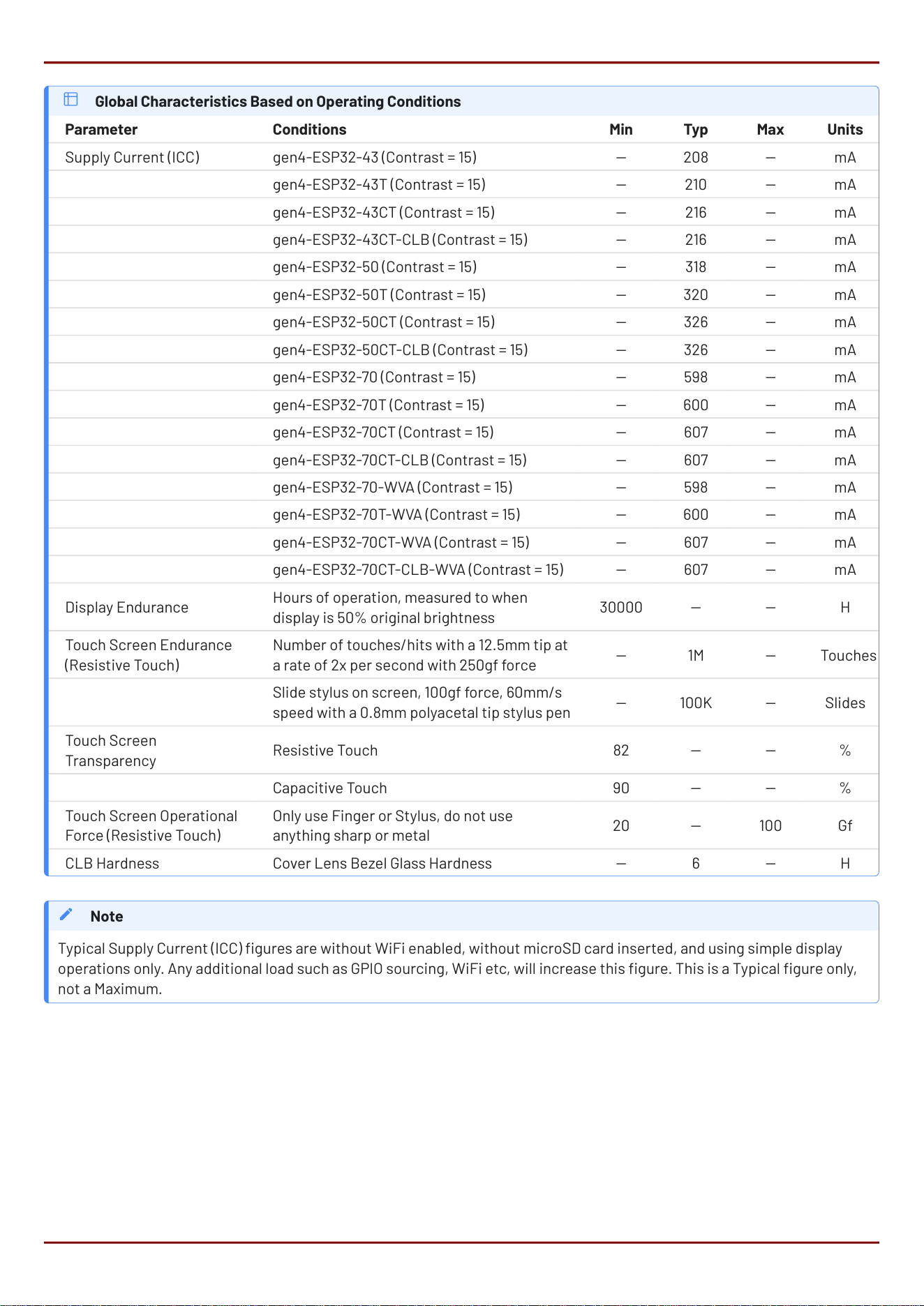
Global Characteristics Based on Operating Conditions
Parameter Conditions Min Typ Max Units
Supply Current (ICC) *** gen4-ESP32-43 (Contrast = 15) 208 mA
gen4-ESP32-43T (Contrast = 15) 210 mA
gen4-ESP32-43CT (Contrast = 15) 216 mA
gen4-ESP32-43CT-CLB (Contrast = 15) 216 mA
gen4-ESP32-50 (Contrast = 15) 318 mA
gen4-ESP32-50T (Contrast = 15) 320 mA
gen4-ESP32-50CT (Contrast = 15) 326 mA
gen4-ESP32-50CT-CLB (Contrast = 15) 326 mA
gen4-ESP32-70 (Contrast = 15) 598 mA
gen4-ESP32-70T (Contrast = 15) 600 mA
gen4-ESP32-70CT (Contrast = 15) 607 mA
gen4-ESP32-70CT-CLB (Contrast = 15) 607 mA
gen4-ESP32-70-WVA (Contrast = 15) 598 mA
gen4-ESP32-70T-WVA (Contrast = 15) 600 mA
gen4-ESP32-70CT-WVA (Contrast = 15) 607 mA
gen4-ESP32-70CT-CLB-WVA (Contrast = 15) 607 mA
Display Endurance
Hours of operation, measured to when
display is 50% original brightness
30000 H
Touch Screen Endurance
(Resistive Touch)
Number of touches/hits with a 12.5mm tip at
a rate of 2x per second with 250gf force
1M Touches
Slide stylus on screen, 100gf force, 60mm/s
speed with a 0.8mm polyacetal tip stylus pen
100K Slides
Touch Screen
Transparency
Resistive Touch 82 %
Capacitive Touch 90 %
Touch Screen Operational
Force (Resistive Touch)
Only use Finger or Stylus, do not use
anything sharp or metal
20 100 Gf
CLB Hardness Cover Lens Bezel Glass Hardness 6 H
Typical Supply Current (ICC) gures are without WiFi enabled, without microSD card inserted, and using simple display
operations only. Any additional load such as GPIO sourcing, WiFi etc, will increase this gure. This is a Typical gure only,
not a Maximum.
Note
gen4-ESP32-RGB Series Specications
4D Systems
DATASHEET
Page 42 of 46
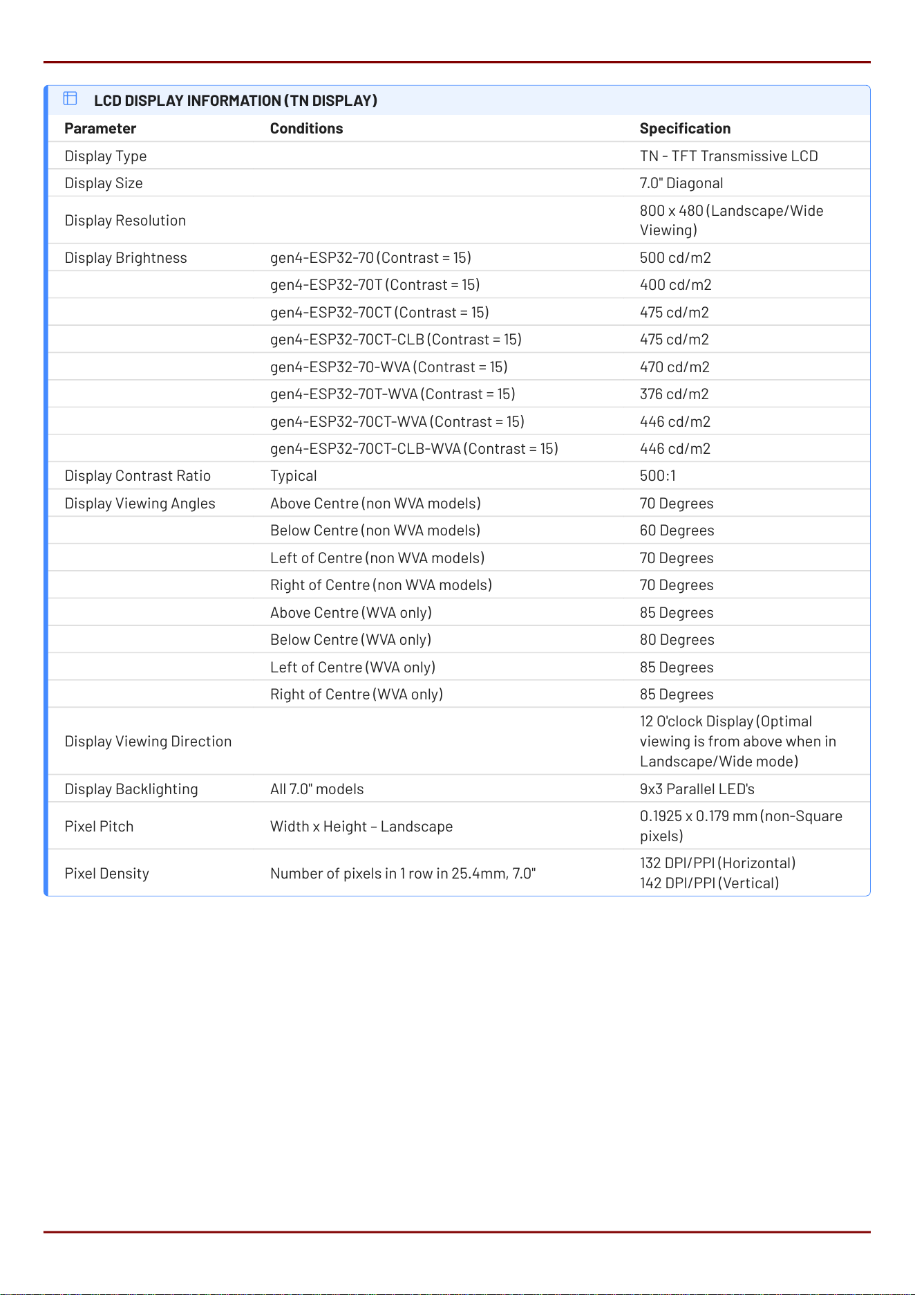
LCD DISPLAY INFORMATION (TN DISPLAY)
Parameter Conditions Specication
Display Type TN - TFT Transmissive LCD
Display Size 7.0" Diagonal
Display Resolution
800 x 480 (Landscape/Wide
Viewing)
Display Brightness gen4-ESP32-70 (Contrast = 15) 500 cd/m2
gen4-ESP32-70T (Contrast = 15) 400 cd/m2
gen4-ESP32-70CT (Contrast = 15) 475 cd/m2
gen4-ESP32-70CT-CLB (Contrast = 15) 475 cd/m2
gen4-ESP32-70-WVA (Contrast = 15) 470 cd/m2
gen4-ESP32-70T-WVA (Contrast = 15) 376 cd/m2
gen4-ESP32-70CT-WVA (Contrast = 15) 446 cd/m2
gen4-ESP32-70CT-CLB-WVA (Contrast = 15) 446 cd/m2
Display Contrast Ratio Typical 500:1
Display Viewing Angles Above Centre (non WVA models) 70 Degrees
Below Centre (non WVA models) 60 Degrees
Left of Centre (non WVA models) 70 Degrees
Right of Centre (non WVA models) 70 Degrees
Above Centre (WVA only) 85 Degrees
Below Centre (WVA only) 80 Degrees
Left of Centre (WVA only) 85 Degrees
Right of Centre (WVA only) 85 Degrees
Display Viewing Direction
12 O'clock Display (Optimal
viewing is from above when in
Landscape/Wide mode)
Display Backlighting All 7.0" models 9x3 Parallel LED's
Pixel Pitch Width x Height – Landscape
0.1925 x 0.179 mm (non-Square
pixels)
Pixel Density Number of pixels in 1 row in 25.4mm, 7.0"
132 DPI/PPI (Horizontal)
142 DPI/PPI (Vertical)
gen4-ESP32-RGB Series Specications
4D Systems
DATASHEET
Page 43 of 46
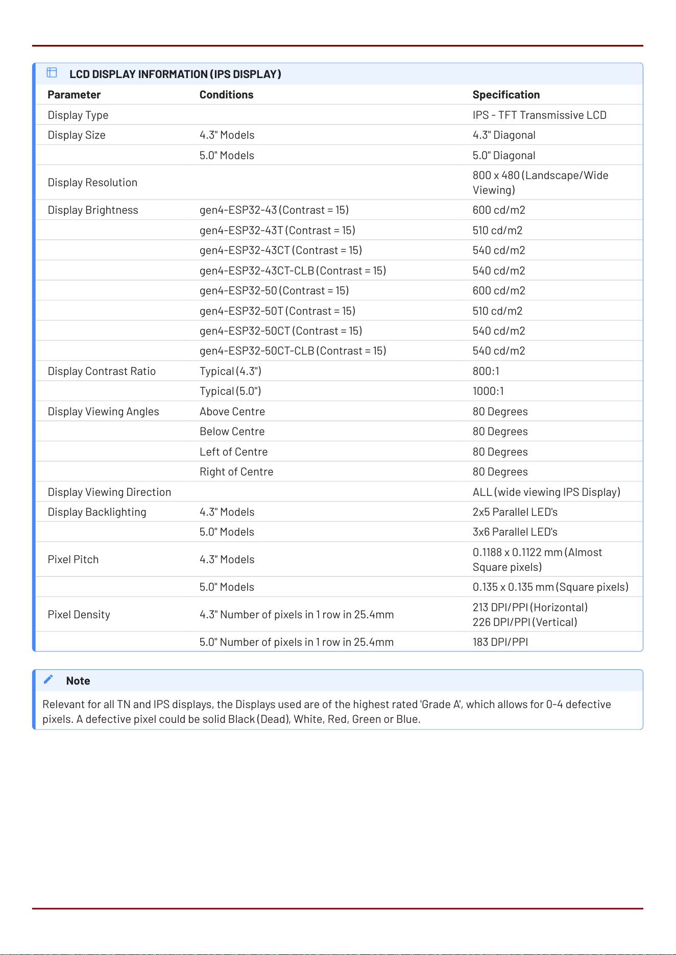
LCD DISPLAY INFORMATION (IPS DISPLAY)
Parameter Conditions Specication
Display Type IPS - TFT Transmissive LCD
Display Size 4.3" Models 4.3" Diagonal
5.0" Models 5.0" Diagonal
Display Resolution
800 x 480 (Landscape/Wide
Viewing)
Display Brightness gen4-ESP32-43 (Contrast = 15) 600 cd/m2
gen4-ESP32-43T (Contrast = 15) 510 cd/m2
gen4-ESP32-43CT (Contrast = 15) 540 cd/m2
gen4-ESP32-43CT-CLB (Contrast = 15) 540 cd/m2
gen4-ESP32-50 (Contrast = 15) 600 cd/m2
gen4-ESP32-50T (Contrast = 15) 510 cd/m2
gen4-ESP32-50CT (Contrast = 15) 540 cd/m2
gen4-ESP32-50CT-CLB (Contrast = 15) 540 cd/m2
Display Contrast Ratio Typical (4.3") 800:1
Typical (5.0") 1000:1
Display Viewing Angles Above Centre 80 Degrees
Below Centre 80 Degrees
Left of Centre 80 Degrees
Right of Centre 80 Degrees
Display Viewing Direction ALL (wide viewing IPS Display)
Display Backlighting 4.3" Models 2x5 Parallel LED's
5.0" Models 3x6 Parallel LED's
Pixel Pitch 4.3" Models
0.1188 x 0.1122 mm (Almost
Square pixels)
5.0" Models 0.135 x 0.135 mm (Square pixels)
Pixel Density 4.3" Number of pixels in 1 row in 25.4mm
213 DPI/PPI (Horizontal)
226 DPI/PPI (Vertical)
5.0" Number of pixels in 1 row in 25.4mm 183 DPI/PPI
Relevant for all TN and IPS displays, the Displays used are of the highest rated 'Grade A', which allows for 0-4 defective
pixels. A defective pixel could be solid Black (Dead), White, Red, Green or Blue.
Note
gen4-ESP32-RGB Series Specications
4D Systems
DATASHEET
Page 44 of 46
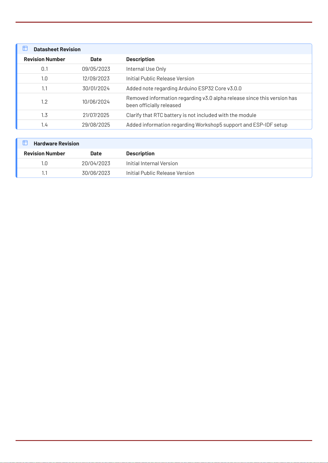
20. Revision History
Datasheet Revision
Revision Number Date Description
0.1 09/05/2023 Internal Use Only
1.0 12/09/2023 Initial Public Release Version
1.1 30/01/2024 Added note regarding Arduino ESP32 Core v3.0.0
1.2 10/06/2024
Removed information regarding v3.0 alpha release since this version has
been ocially released
1.3 21/07/2025 Clarify that RTC battery is not included with the module
1.4 29/08/2025 Added information regarding Workshop5 support and ESP-IDF setup
Hardware Revision
Revision Number Date Description
1.0 20/04/2023 Initial Internal Version
1.1 30/06/2023 Initial Public Release Version
gen4-ESP32-RGB Series Revision History
4D Systems
DATASHEET
Page 45 of 46

21. Legal Notice
21.1. Proprietary Information
The information contained in this document is the property of 4D Systems Pty. Ltd. and may be the subject of patents
pending or granted, and must not be copied or disclosed without prior written permission. 4D Systems endeavours to ensure
that the information in this document is correct and fairly stated but does not accept liability for any error or omission. The
development of 4D Systems products and services is continuous and published information may not be up to date. It is
important to check the current position with 4D Systems. 4D Systems reserves the right to modify, update or makes changes
to Specications or written material without prior notice at any time.
All trademarks belong to their respective owners and are recognised and acknowledged.
21.2. Disclaimer of Warranties & Limitations of Liabilities
4D Systems makes no warranty, either expressed or implied with respect to any product, and specically disclaims all other
warranties, including, without limitation, warranties for merchantability, non-infringement and tness for any particular
purpose.
Information contained in this publication regarding device applications and the like is provided only for your convenience and
may be superseded by updates. It is your responsibility to ensure that your application meets with your specications.
Images and graphics used throughout this document are for illustrative purposes only. All images and graphics used are
possible to be displayed on the 4D Systems range of products, however the quality may vary.
In no event shall 4D Systems be liable to the buyer or to any third party for any indirect, incidental, special, consequential,
punitive or exemplary damages (including without limitation lost prots, lost savings, or loss of business opportunity) arising
out of or relating to any product or service provided or to be provided by 4D Systems, or the use or inability to use the same,
even if 4D Systems has been advised of the possibility of such damages.
4D Systems products are not fault tolerant nor designed, manufactured or intended for use or resale as on line control
equipment in hazardous environments requiring fail - safe performance, such as in the operation of nuclear facilities, aircraft
navigation or communication systems, air trac control, direct life support machines or weapons systems in which the
failure of the product could lead directly to death, personal injury or severe physical or environmental damage ('High Risk
Activities'). 4D Systems and its suppliers specically disclaim any expressed or implied warranty of tness for High Risk
Activities.
Use of 4D Systems' products and devices in 'High Risk Activities' and in any other application is entirely at the buyer's risk, and
the buyer agrees to defend, indemnify and hold harmless 4D Systems from any and all damages, claims, suits, or expenses
resulting from such use. No licenses are conveyed, implicitly or otherwise, under any 4D Systems intellectual property rights.
gen4-ESP32-RGB Series Legal Notice
4D Systems
DATASHEET
Page 46 of 46

FCC Warnning:
This equipment has been tested and found to comply with the limits for a Class B digital device,
pursuant to part 15 of the FCC Rules. These limits are designed to provide
reasonable
protection against harmful interference in a residential installation. This equipment generates,
uses and can radiate radio
frequency
energy
and,
if
not
installed
and
used
in
accordance
with
the
instructions,
may cause
harmful
interference
to
radio
communications.
However,
there is
no
guarantee
that interference
will
not
occur
in
a
particular
installation.
If
this equipment
does
cause
harmful interference to radio or television reception, which can be determined by
turning the equipment off
and
on,
the
user
is
encouraged
to
try
to
correct
the interference
by
one
or
more
of
the following measures:
• Reorient or relocate the receiving antenna.
• Increase the separation between the equipment and receiver.
•
Connect the equipment into an outlet on a circuit different from that to which the receiver is
connected.
• Consult the dealer or an experienced radio/TV technician for help.
Caution:
Any
changes
or
modifications
to
this
device
not
explicitly
approved
by
manufacturer
could void your authority to operate this equipment.
This
device
complies
with
part
15
of
the
FCC
Rules.
Operation
is
subject
to
the
following
two
conditions:
(1)This
device
may
not
cause
harmful
interference,
and
(2)
this
device
must
accept
any
interference received, including interference that may cause undesired operation.
This
equipment
complies
with
FCC
radiation
exposure
limits
set
forth
for
an
uncontrolled
environment.
This
equipment
should
be
installed
and
operated
with
minimum
distance
20cm
between the radiator and your body.