1
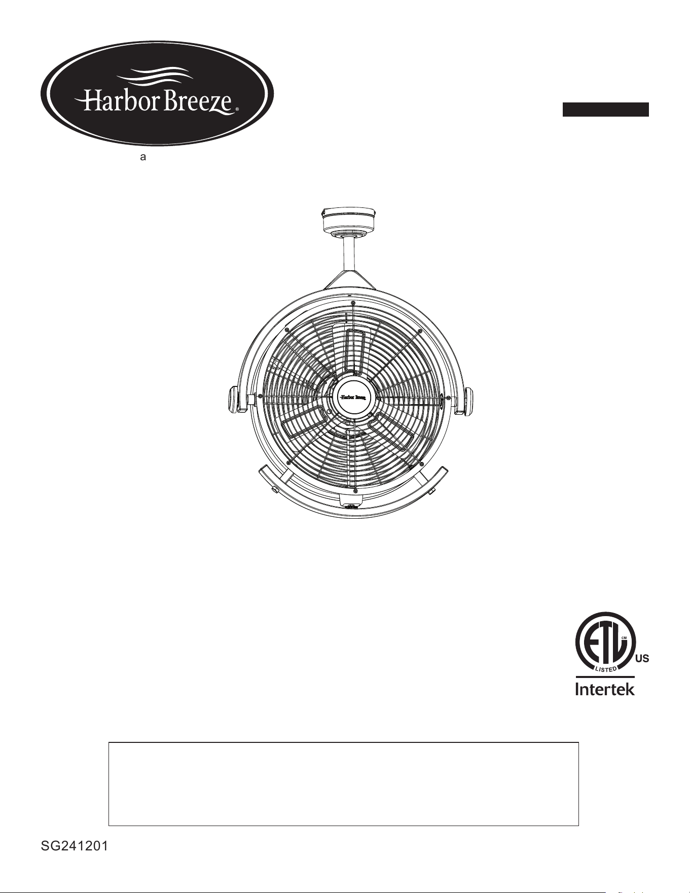
ITEM #5303206
MODEL #42955
GARAGE FAN
ATTACH YOUR RECEIPT HERE
SG241201
Español p. 12
HARBOR BREEZE and logo design are trademarks or
registered trademarks of LF, LLC. All rights reserved.
Purchase Date _________________________
Thank you for purchasing this HARBOR BREEZE product.
Questions, problems, or missing parts?
Before returning, contact us at:
888-251-1003, 8 a.m. - 8 p.m., EST, Monday - Sunday or at [email protected].

2
TABLE OF CONTENTS
Package Contents .................................................................3
Hardware Contents ................................................................4
Safety Information .................................................................4
Preparation ......................................................................4
Assembly Instructions ..............................................................5
Replace Downrod .................................................................9
Operating Instructions .............................................................10
Care and Maintenance ............................................................11
Troubleshooting ..................................................................11
Limited Lifetime Warranty ..........................................................11
Replacement Parts ...............................................................12
33
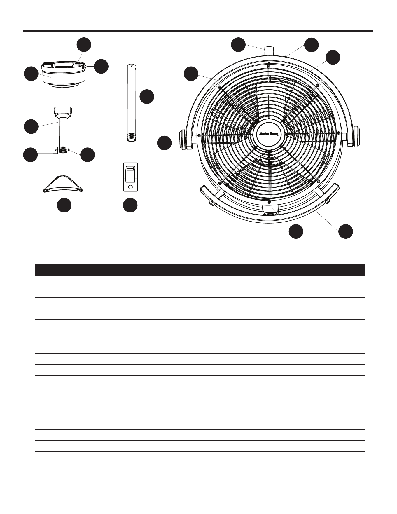
PACKAGE CONTENTS
PART DESCRIPTION QUANTITY
A Mounting Bracket (preassembled to Canopy [B]) 1
B Canopy 1
C Mounting Bracket Screw (preassembled to Mounting Bracket [A]) 4
D Downrod 1
E Downrod Clip (preassembled to Downrod [D]) 1
F Downrod Pin (preassembled to Downrod [D]) 1
G Yoke Cover 1
H 12-Inch Downrod (optional) 1
I Cord Clip 6
J Yoke (preassembled to Fan Assembly [K]) 1
K Fan Assembly 1
L Tilt Knob (preassembled to Fan Assembly [K]) 2
M Speed Control (preassembled to Fan Assembly [K]) 1
N Adjustment Handle (preassembled to Fan Assembly [K]) 1
O Cord Bracket (preassembled to Fan Assembly [K]) 2
P Yoke Cover Screw (preassembled to Fan Assembly [K]) 2
A
B
C
D
E F
M
L
K
N
O
P
G
H
I
J
4
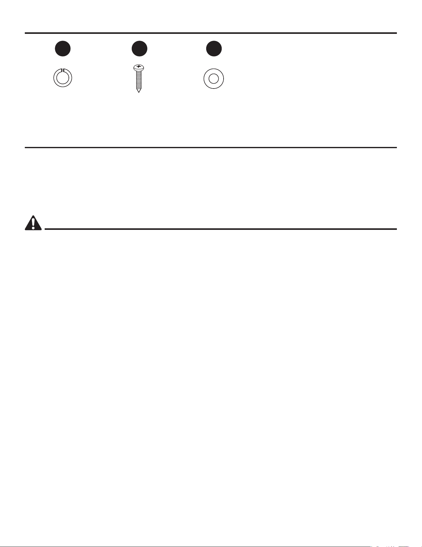
HARDWARE CONTENTS
Lock Washer
Qty. 2
Wood Screw
Qty. 2
Washer
Qty. 2
PREPARATION
Before beginning the assembly of this product, ensure that all parts are present. Compare all parts
with the package contents list and hardware contents list. If any part is missing or damaged, do not
attempt to assemble the product.
Estimated Assembly Time: 30 minutes
Tools Required for Assembly (not included): Step Ladder and Phillips Screwdriver.
HH RR UU
SAFETY INFORMATION
CAUTION:
• Read and follow all instructions before operating fan.
• Do not use fan if any part is damaged or missing.
• This garage fan is rated for indoor and damp locations.
• Connect to properly grounded outlets only.
• Do not insert ngers or any other objects through the grill guard when fan is in operation.
• Disconnect the fan when moving from one location to another.
• When the fan is not in use or before cleaning, unplug the fan from the outlet.
• Do not use fan near windows. Rain and water may create an electrical hazard.
• Do not alter the fan’s assembly.
WARNING:
• To reduce the risk of re or electrical shock, do not use this fan with any solid state speed control
device.This appliance has a 3-prong plug. To reduce the risk of electrical shock, this plug is intended
to t in an outlet only one way. If this does not t the outlet, contact a qualied electrician. Do not
attempt to bypass this procedure.
• Failure to secure set screws on sides of the mounting bracket may result in fan falling causing
serious injury or death.
• To protect against the risk of electrical shock, do not immerse the unit, cord or plug in water or other
liquid.
• Do not plug/unplug the fan into/from the electrical outlet with wet hand.
5
ASSEMBLY INSTRUCTIONS
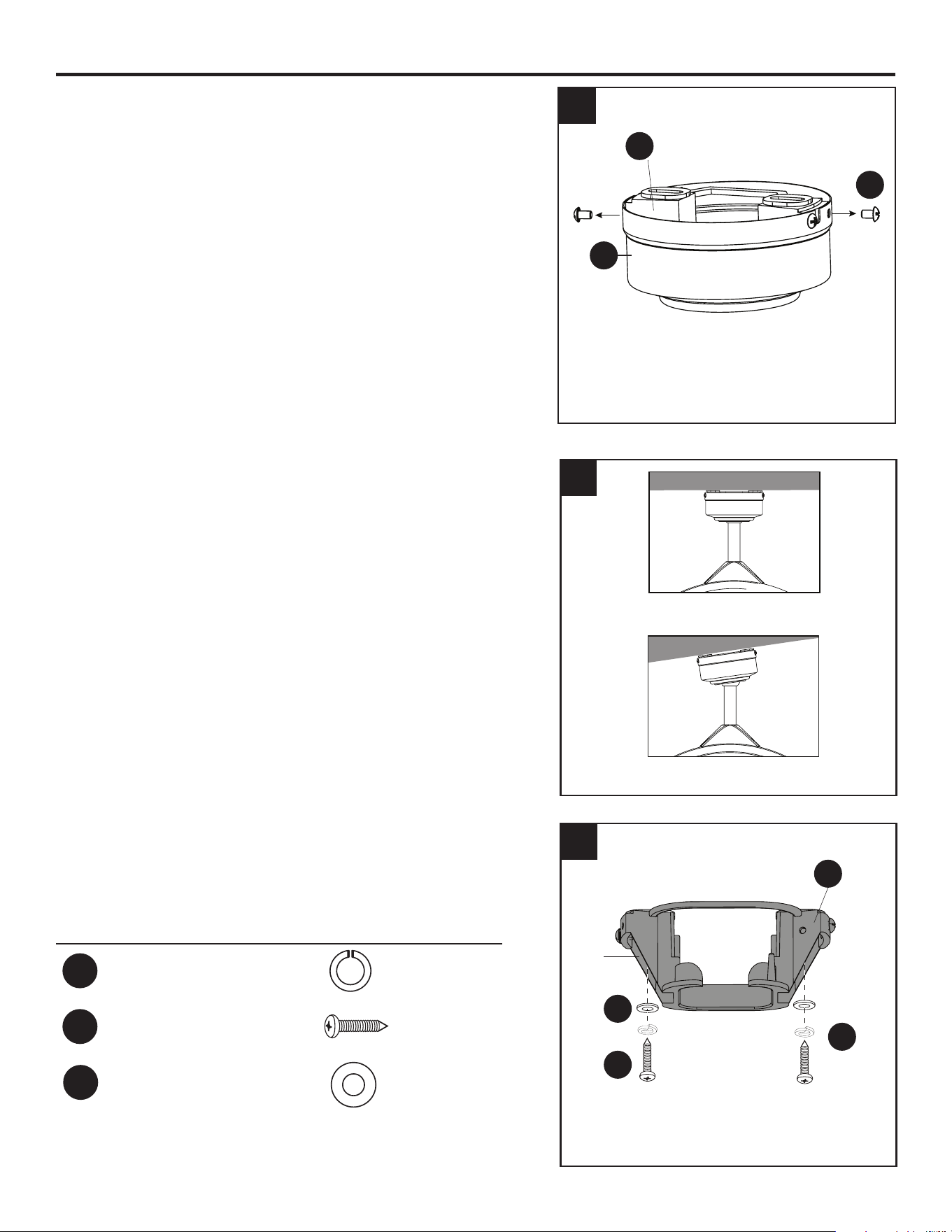
1. Loosen all four mounting bracket screws (C) and
completely remove the two screws from the round holes
in the canopy (B). Save the screws for later. Remove
the canopy (B) from the mounting bracket (A).
2. Determine the mounting method to use.
Standard Mounting is best suited for ceilings 8 ft. or
higher. For taller ceilings you may want to use a longer
downrod (not included).
Angle Mounting is best suited for angled or vaulted
ceilings. Important: If using the angle mount, check to
ensure the ceiling angle is not steeper than 12°.
3. Use 2 wood screws (RR) along with washer (UU) and
lock washer (HH) to secure the mounting bracket (A) to
ceiling joists. Then, loosen but do not remove two set
screws on each side of the mounting bracket (A).
Hardware Used
HH
Lock Washer x 2
RR
Wood Screw x 2
Washer x 2
1
A
UU
HH
RR
C
B
A
3
Set
Screw
UU
2
Standard Mounting
Angle Mounting
6
ASSEMBLY INSTRUCTIONS
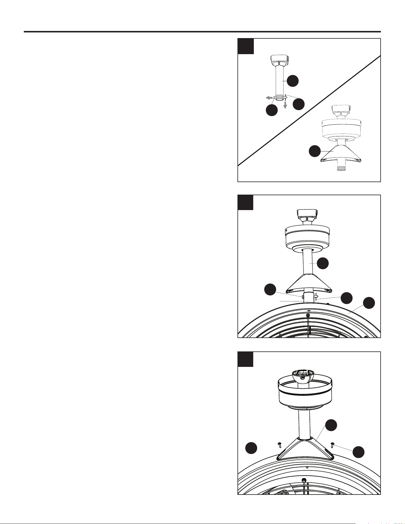
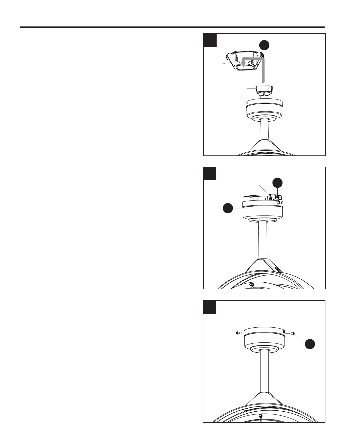
4. The fan includes an optional 12-inch downrod (H).
The 6-inch downrod is preassembled to the square
bracket. If longer downrod is needed, see REPLACE
DOWNROD, page 9. Then, remove the downrod clip
(E) and downrod pin (F) from the downrod (D). Insert
the downrod (D or H) through the canopy (B) and yoke
cover (G).
5. Slide the downrod (D or H) into the yoke at the top of
the fan assembly (K) and turn clockwise to tighten.
Align the holes, then reinstall the downrod pin (F) and
downrod clip (E) to secure.
6. Remove the two yoke cover screws (P) preassembled
to the top of the fan assembly (K). Use the two yoke
cover screws (P) to secure the yoke cover (G) to the
top of the fan assembly (K). Then, lower the yoke cover
(G) to rest on top of fan assembly (K).
5
6
5
K
K
E
F
D
Yoke
P
G
4
D
E
G
F
7
ASSEMBLY INSTRUCTIONS
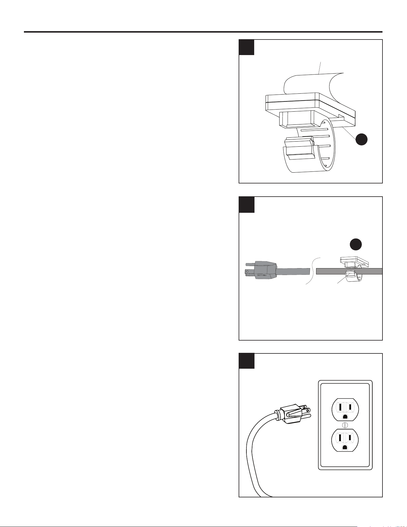
7. Install the square bracket into the opening of the
mounting bracket (A). Tabs on square bracket should
face the sides of the mounting bracket (A) to engage
the slots inside the mounting bracket (A). Retighten the
two set screws to secure.
8. Raise the canopy (B), ensure the two mounting bracket
screws (C) are aligned with the J-shaped slots in the
canopy (B). Then turn the canopy (B) in a clockwise
direction until the mounting bracket screws (C) are
completely engaged in the J-shaped slots.
9. Install the two previously removed mounting bracket
screws (C) in the round holes. Securely tighten all
mounting bracket screws (C).
9
8
J-Shaped Slot
5
7
Tab
Set
Screw
Square Bracket
A
B
C
C
8
ASSEMBLY INSTRUCTIONS
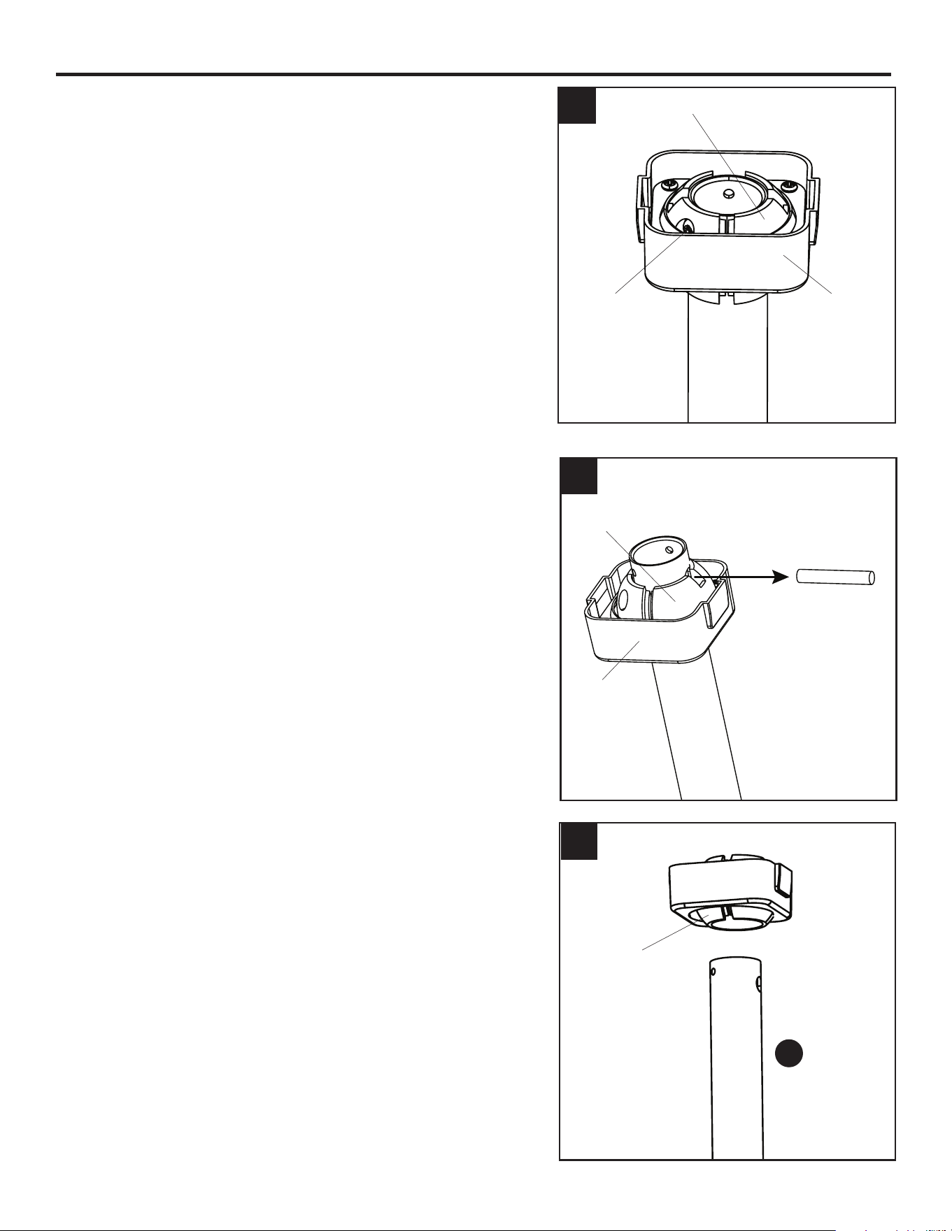
10. Use cord clips (I) to secure the fan’s power cord to
ceiling in a path toward the power outlet.
Peel the backing o of the double-sided tape
preassembled to back side of each cord clip (I). Note:
Cord clips have a round hole to accommodate a wood
screw (sold separately) as an option to the taping
method.
11. Secure each cord clip (I) to the ceiling. Then insert the
cord into each clip and press the clip closed to secure
the cord. Note: Leave adequate slack near the fan to
allow fan to swivel and/or tilt.
12. Plug power cord into a grounded 120v outlet.
12
11
Clip
I
10
Backing
I
9
REPLACE DOWNROD (OPTIONAL)
1. Tilt the downrod ball in the square bracket to access
and remove the set screw with Phillips screwdriver.
2. Lower the downrod ball and square bracket to access
and remove the pin.
3. Remove the downrod (D) and exchange with the
12-inch downrod (H). Slide extra downrod into downrod
ball. Replace the pin and set screw as shown in
previous steps.
3
1
H
2
Set Screw Square
Bracket
Square
Bracket
Pin
Downrod
Ball
Downrod
Ball
Downrod
Ball
10
OPERATING INSTRUCTIONS
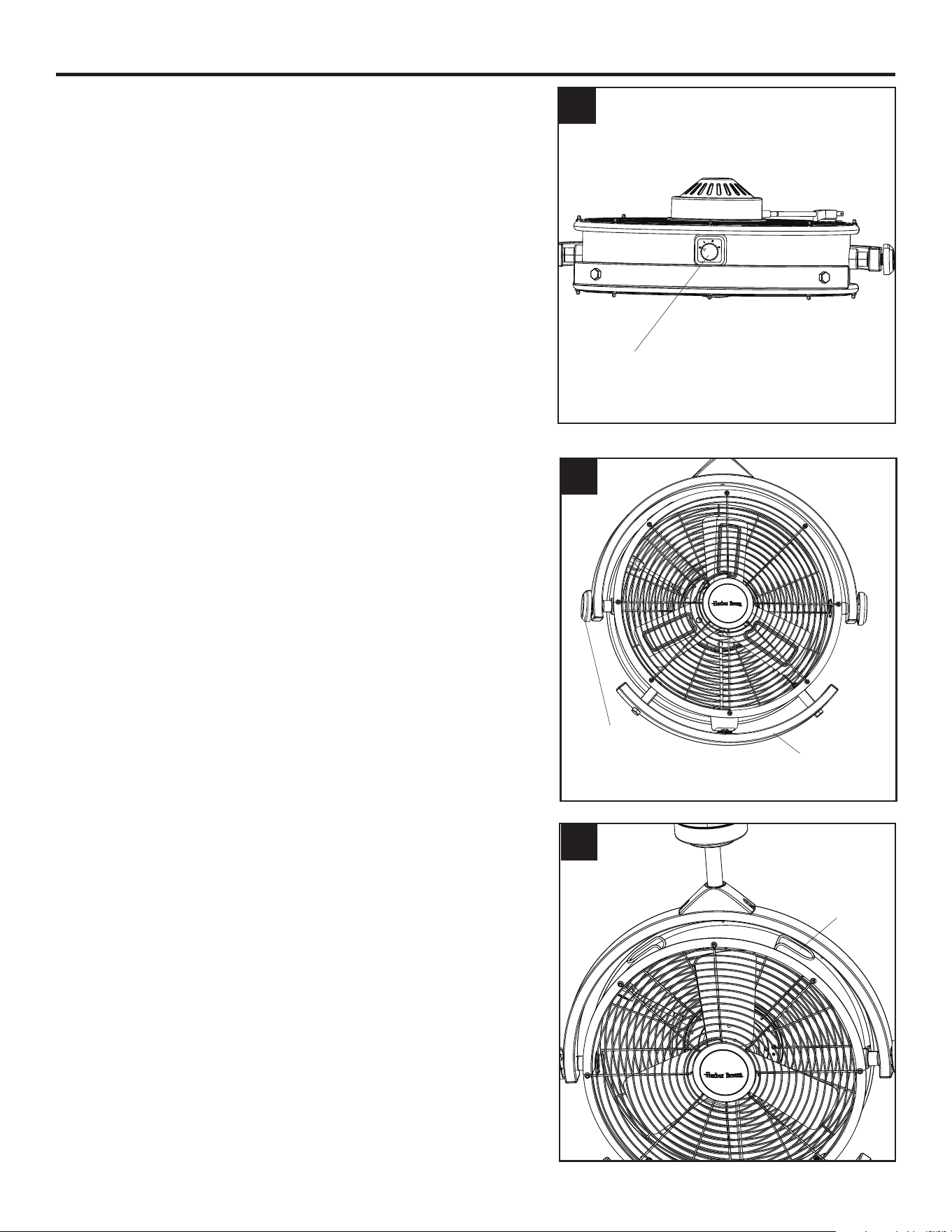
1. Fan Control is located on the bottom side of the fan.
The fan has four settings:
0 - O
1 - Low Speed
2 - Medium Speed
3 - High Speed
2. Use tilt knobs on sides of fan to adjust airow up or
down. Loosen tilt knobs by turning counterclockwise,
adjust fan, and retighten tilt knobs.
Use adjustment handle located on bottom of fan to
change the direction of airow from left to right.
3. Cord brackets are located on top of fan assembly (K).
When not in use, wrap power cord around the two cord
brackets.
3
1
2
Speed
Control
Tilt Knob Adjustment
Handle
Cord
Bracket
11
CARE AND MAINTENANCE
At least twice each year, tighten all screws on the fan. Clean the fan assembly with only a soft brush
or lint-free cloth to avoid scratching the nish.
Important: Unplug the fan from outlet before you begin any maintenance tasks. Do not use water or
a damp cloth to clean the ceiling fan.
TROUBLESHOOTING
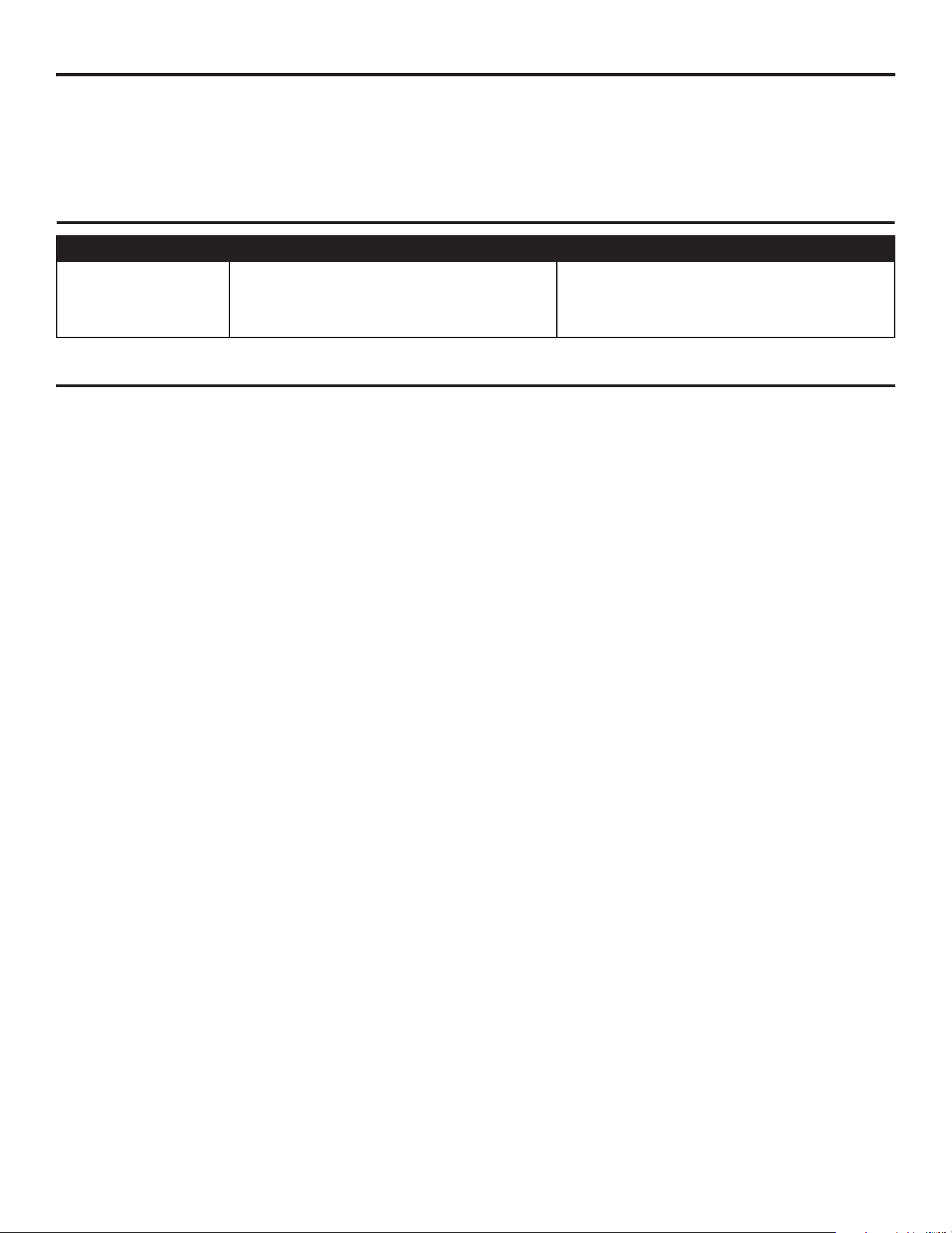
PROBLEM POSSIBLE CAUSE CORRECTIVE ACTION
The fan does not
move.
The power is o, fuse is blown, or
breaker is tripped.
Turn the power on or check the fuse
or breaker.
LIMITED LIFETIME WARRANTY
Set forth below, the manufacturer warrants the fan motor for this ceiling fan to be free from defects
in workmanship and material for the life of the product. Also, subject to the limitations below, the
manufacturer warrants all ceiling fan parts (“ceiling fan parts” excludes the motor and parts made in
whole or in part with glass) to be free from defects in workmanship and material for a period of one
year after the date of purchase by the original purchaser at retail.
All claims must be made by the original purchaser from an authorized dealer, whether such purchaser
purchased the product through a store or contractor. Ceiling fan part defects must be reported within
the rst year from the date of purchase. Parts made in whole or in part with glass and the nishes of
metal and other surfaces are not warranted.
Purchasers are responsible for all costs of removing and reinstalling the product. Any damage to any
part caused by ordinary wear and tear, accident, misuse, or improper installation, is not covered by
this warranty. The manufacturer assumes no responsibility whatsoever for fan installation. Any service
performed by a non-licensed electrician will render the warranty invalid.
The manufacturer’s sole responsibility shall be to repair or replace the motor, parts, or product within
the terms stated above. The manufacturer shall not be liable for any loss or damage of any kind,
including any incidental or consequential damages resulting directly or indirectly, from any breach
of warranty, express or implied, or any other failure of this product. Some states do not allow the
exclusion or limitation of incidental or consequential damages so this limitation may not apply to you.
If the original purchaser ceases to own the fan, this warranty is voided.
Should the purchaser encounter a problem with your fan related to defects in workmanship or
materials within the warranty period associated with the defective part, the manufacturer agrees to
replace the defective part without charge, or at its option, to replace the ceiling fan with a comparable
or superior model.
The manufacturer’s warranties are limited to the written warranties set out in this ceiling fan limited
lifetime warranty. All other express and implied warranties, including, without limitation, the implied
warranty of tness for a particular purpose and the implied warranty of merchantability is disclaimed.
Some states do not allow the disclaimer of implied warranties, so this disclaimer may not apply to
you.
12
9881 PB · 101624 Printed in China
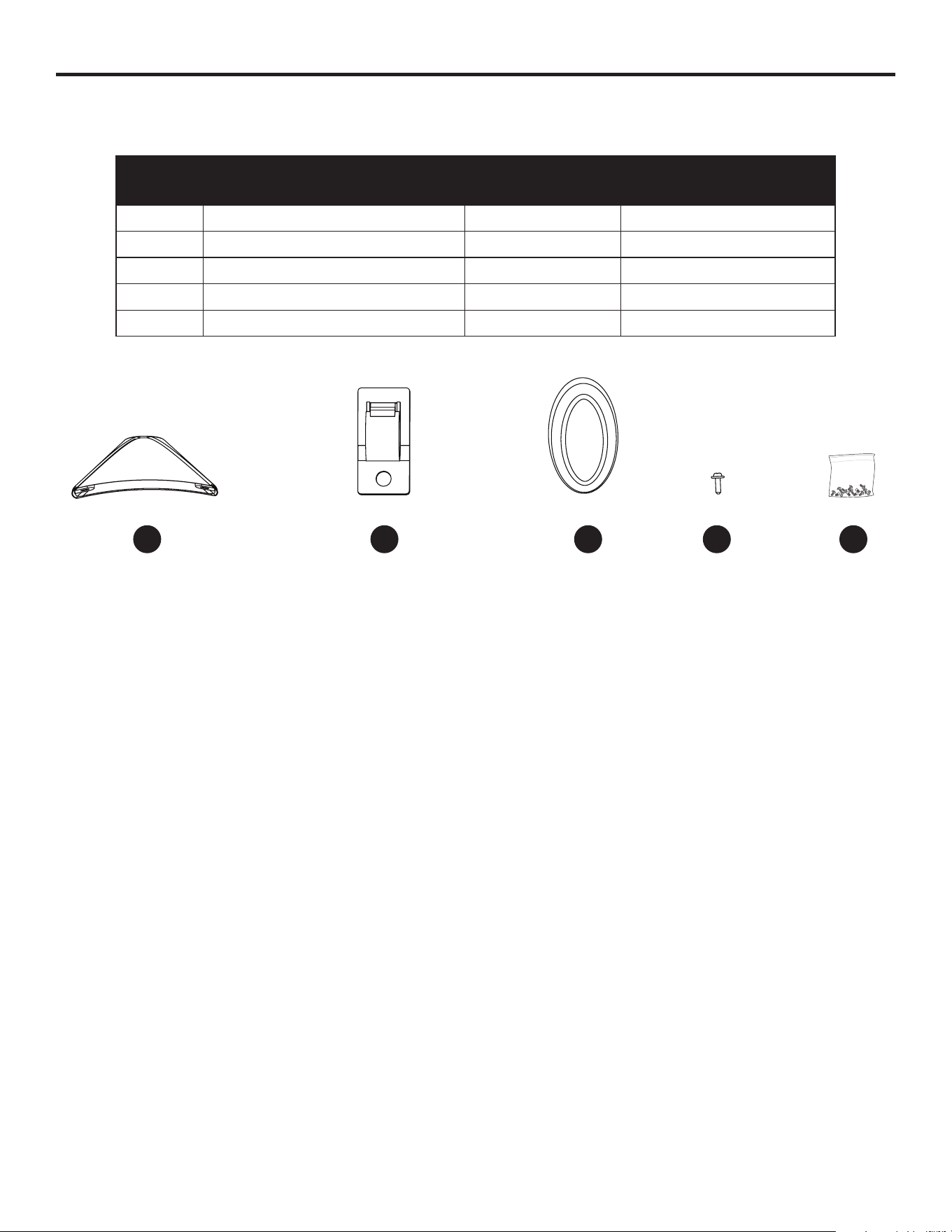
REPLACEMENT PARTS LIST
For replacement parts, call the customer service department at 888-251-1003, 8 a.m. - 8 p.m., EST,
Monday - Sunday. You could also contact us at [email protected].
PART DESCRIPTION PART# COVERED UNDER
WARRANTY
G Yoke Cover 4A000024960 YES - 1 year
I Cord Clip 4A000025310 YES - 1 year
L Tilt Knob 4A000025320 YES - 1 year
P Yoke Cover Screw (x2)
4A000025330 YES - 1 year
HW Hardware Bag 4A000025340 NO
G I L P HW