Electric Heater
Model
WTM-X
series
INSTALLATION
INSTRUCTIONS
Date: 08/25/2020
GENERAL
This
electric
heater
series
is
engineered,
designed,
and
approved
to
be
installed
in
the
Pioneer
DR
series
air
handlers.
Before
proceeding,
check
the
heater
label
for
the
correct
voltage
and
KW
requirements.
details.
Verify
that
all
elements are
properly
secure
in
their
ceramic
holders.
Installation
and
servicing
of
this
equipment
should
only
be
performed
by
trained
and
qualfied
personnel
and
NOT
accesible
to
the general public.
Before
proceeding
with
the
heater
installation,
inspect
thoroughly
for
shipping
damage.
Notifiy
the
shipper
immediately
if
any
damage
is
found.
Check
all
porcelain
insulaors
for
breakage
and
inspect
heater
element
wire
to
see
that
none
have
been
deformed.
Clean
al
dirt,
dust
and
moisture
from
equipment.
Check
for
proper
clearances
of
live
parts,
between
phases,
and
to
ground.
Make
sure
that
all
required
barriers
are
in
place.
Check
conductors
run
in
multiple
to
insure
that
they
are
properly
wired.
Refer
to
base
installation
instructions
for
complete
unit
installation
SAFETY
WARNING
HEATER
INSTALLATION
This
appliance
is
not
intended
for
use
by
persons
(including
children)
with
reduced
physical,
sensory,
or
mental
capabilities,
or
lack
of
experience
and
knowledge,
unless
they
have
been
given
supervision
or
instruction
concerning
use
of
the
appliance
by
a
person
responsible
for
their
safety.
Children
should
be
supervised
to
ensure
that
they
do
not
play
with
the
appliance.
Note:
appliance
not
for
use
exceeding
2000
m.
1.
Refer
to
the
base
unit
installation
instructions
as
required.
Affix
Warren
Heater
installer
label
to
the
equipment
access
panel.
2.
Remove
blower
access
panel
of
the
air
handler
unit.
3.
Remove
cover
plate
from
back
panel
of
air
handler
control
and
wiring
compartment.
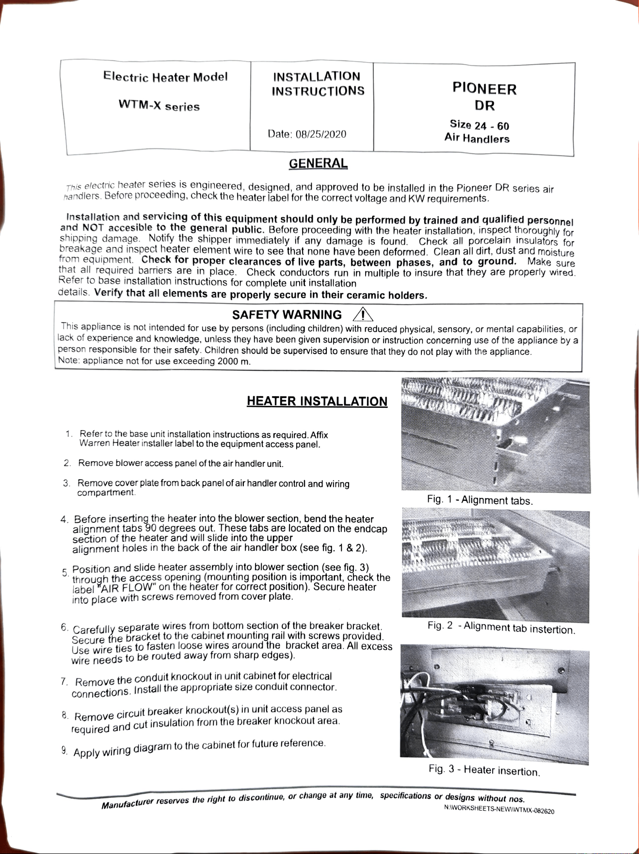
4.
Before
inserting
the
heater
into
the
blower
section,
bend
the
heater
alignment
tabs
90
degrees
out.
These
tabs
are
located
on
the
endcap
section
of
the
heater
and
will
slide
into
the
upper
alignment
holes
in
the
back
of
the
air
handler
box
(see
fig.
1 &
2).
E
Position
and
slide
heater
assembly
into
blower
section
(see
fig.
3)
through
the
access
opening
(mounting
position
is
important,
chek
the
label
YAIRFLOW"
on
the
heater
for
correct
position).
Secure
heater
into
place
with
Screws
removed
from
cover
plate.
6.
Carefullv
separate
wires
from
bottom
section
of
the
breaker
bracket
Secure
the
bracket
to
the
cabinet
mounting
rail
with
screws
provided
Use
wire
ties
to
fasten
loose
Wires
arOund
the
bracket
area.
All
excess
wire
needs
to
be
routed
away
trom
sharp
edges).
PIONEER
DR
7.
Remove
the
conduit
knockout
in
unit
cabinet
for
electrical
connections.
Install
the
appropriate
size
Conduit
connector.
Size
24
-
60
Air
Handlers
8.
Remove
circuit
breaker
knockout(s)
in
unit
access
panel
as
reguired
and
cut
insulation
from
the
breaker
knockout
area
3.
Apply
wiring
diagram
to
the
cabinet
for
future
reference.
Fig.
1
-Alignment
tabs.
Fig.
2
-
Alignment
tab
instertion.
Fig.
3-
Heater
insertion.
teturer
reserves
the
right
to
discontinue,
or
change a
any
ume,
specitications
or
designs
without
noe
N:WORKSHEETS-NEWIWTMX-082620
WARNING
Before
performing
service
or
maintenance
operations
on
svstem,
turn
off
all
main
power
switches.
There
may
be
more
than
one
disconnect.
Tun
off
accessory
heater
power
switch
if
applicable.
Electrical
shock
can
cause
personal
injury
TAG
DISCONNECT
SWiTCH(ES)
WITH
A
SUITABLE
WARNING
LABEL.
When
installed
in
a
garage,
heater
elements
should
have
a
clearance
of
18"
from
the
floor,
insure
that
the
area
is
ventilated.
1.
All
electrical connections,
wire
sizes and
type
and conduit sizes
shall meet the
National
Electric Code, State and
Local
Codes.
Main
power
supply,
mininmum
wire
sizes,
circuits,
fusing,
etc.
ELECTRICAL
CONNECTIONS
is
shown
on
schematic
wiring
diagrams.
Use
copper
wire
only.
2.
Power
may
be
brought
into
the
unit
through
the
top
when
unit
is
vertical
position
or
through
the
left
or
right
side
panel.
3.
Refer
to
base
unit
instructions
for
recommended
wiring
procedures.
4.
For
electric
heat
installations
connect
the
supply
power
to
the
circuit
breaker supplied
with
the
heater
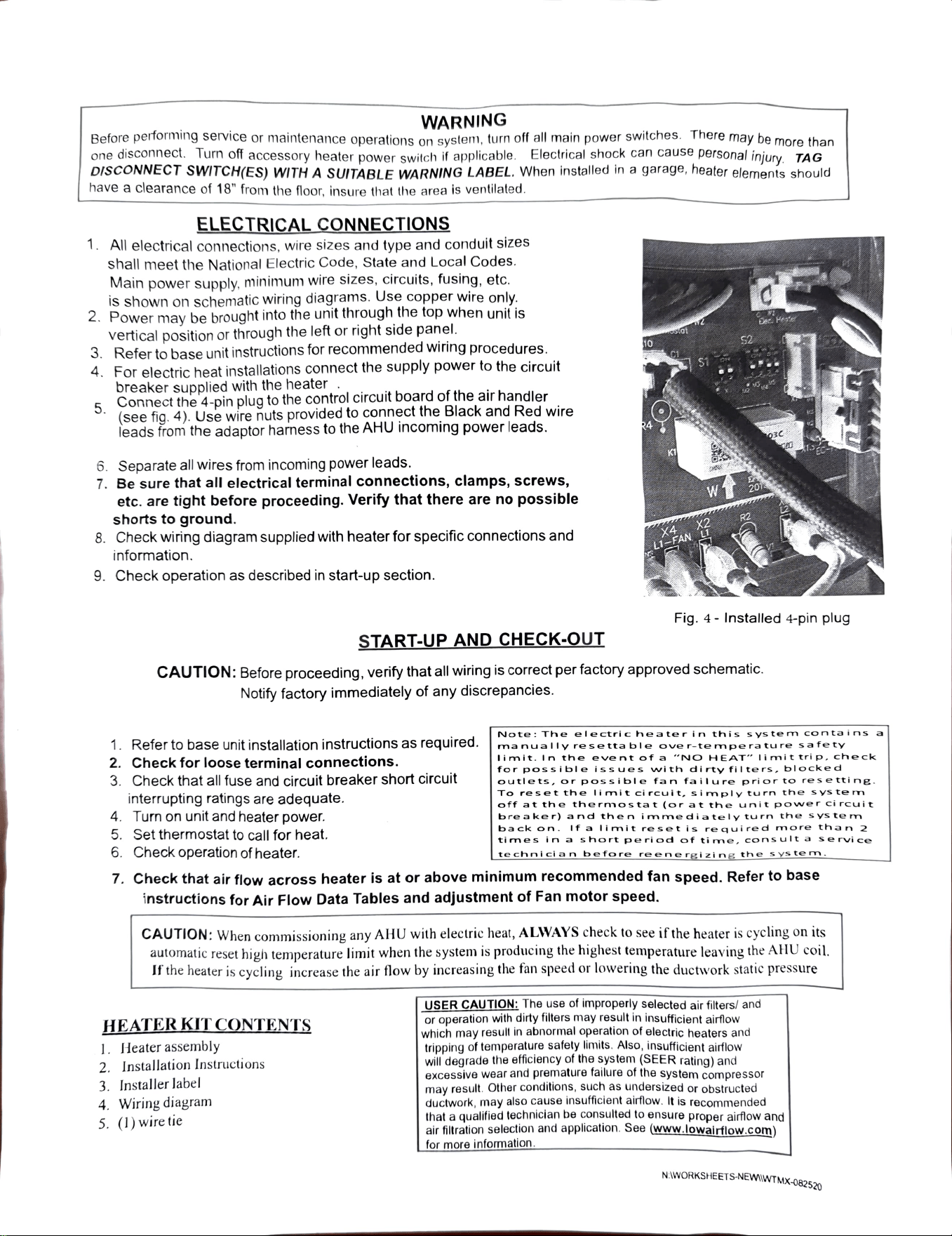
Connect
the
4-pin
plug
to
the
control
circuit
board
of
the
air
handler
(see
fiq.
4).
Use
wire
nuts
provided
to
connect the
Black
and
Red
wire
leads
from
the
adaptor
harness
to
the
AHU
incoming
power
leads.
6.
Separate
all
wires
from
incoming
power
leads.
7.
Be
sure
that
all
electrical
terminal
connections,
clamps,
screws,
etc.
are
tight
before
proceeding.
Verify
that
there
are
no
possible
shorts to ground.
8.
Check
wiring
diagram
supplied
with
heater
for
specific
connections
and
information.
9.
Check operation as
described
in
start-up section.
CAUTION:
Before
proceeding,
verify
that
all
wiring
is
correct
per
factory
approved
schematic.
Notify
factory
immediately
of
any
discrepancies.
1.
Refer
to
base
unit
installation
instructions
as
required.
2..
Check
for
loose
terminal
connections.
3.
Check
that
all
fuse
and
circuit
breaker
short
circuit
interrupting
ratings
are
adequate.
4.
Turn
on
unit
and
heater
power.
5.
Set
thermostat
to
call for heat.
6.
Check
operation
of
heater.
HEATERKIT
CONTENTS
START-UP
AND
CHECK-OUT
7.
Check
that
air
flow
across
heater
is
at
or
above
minimum
recommended
fan
speed.
Refer
to
base
instructions
for
Air
Flow
Data
Tables
and
adjustment
of
Fan
motor
speed.
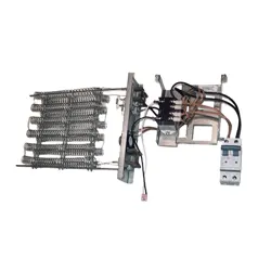
1.
Heater
assembly
CAUTION:
When
commissioning
any
AHU
with
electric
heat,
ALWAYS
check
to
see
if
the
heater
is
cycling
on
its
automatic
reset
high
temperature
limit
when
the
system
is
producing
the
highest
temperature
leaving
the
AlHU
coil.
If
the
heater
is
cycling
increase
the
air
flow
by
increasing
the
fan
speed
or
lowering
the
ductwork
static
pressure
2.
Installation Instructions
3.
Installer
label
Fig.
4-
Installed
4-pin
plug
4.
Wiring
diagram
5.
(1)
wire
tie
Note:
The
ele
ctric
heater
in
this
sys
tem
contai
ns
a
manually
rese
tta
ble
ove
r-te
mpe
rature
safety
Iimit.
In
the
eve
nt
of
a
"NO
HEAT"
imit
trip,
check
for
possible
issues
with
di
rty
fil
te
rs,
blocked
outlets,
or
possible
fan
failure
prior
to
resetti
ng.
To
reset
the
limit
circuit,
simply
turn
the
sys
te
m
off
at
the
thermostat
(orat
the
unit
po
wer
ci
rcuit
bre
aker)
and
then
imme
diately
turn
the
s
ys
tem
back
on.
If
a
limit
reset
is
requi
red
more
than
2
times
in
a s
hort
period
of
time.
Cons
ult
a
service
USER
CAUTION:
The
use
of
improperly
selected
air
filters/
and
or
operation
with
dirty
filters
may
result
in
insufficient
airflow
which
may
result
in
abnormal
operation
of
electric
heaters
and
tripping
of
temperature
safety
limits.
Also,
insufficient
airflow
will
degrade
the
efficiency
of
the
system
(SEER
rating)
and
excessive
wear
and
premature
failure
of
the
system compressor
may
result.
Other
conditions,
such
as
undersized
or
obstructed
ductwork,
may
also cause insufficient
airtlow.
It
is
recommended
that
a
qualified
technician
be
consulted
to
ensure
proper
airflow
and
air
filtration
selection
and
application.
See
(www.lowairflow.com)
for
more
information.
NIWORKSHEETS-NEWIWTMX-082520
te
chnici
an
before
reenergizing
the
sys
te
m.