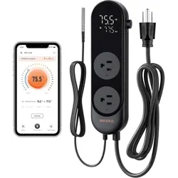
ITC-608T
Manual

Part 1 Quick Guide to Use
The Manual
Is Divided Into
6 Parts.
Part 2 Temperature Controller Manual
Part
3 Programmable Temperature
Controller Manual
Part
5 Humidity Controller Manual
Part
6 Humidity&Temperature
Controller Manual
1
4
12
36
Part
4 Dual Temperature Probes
Controller Manual
26
43
PAGE
12
PAGE
26
1.CAUTION:
KEEP CHILDREN AWAY
TO REDUCE THE RISK OF ELECTRIC SHOCK, USE ONLY
INDOORS
RISK OF ELECTRIC SHOCK. DO NOT PLUG INTO ANOTHER
RELOCATABLE POWER TAPS OR AN EXTENSION CORD.
USE ONLY IN DRY LOCATION
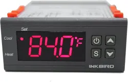
TEMPERATURE
Controller Manual
Equivalent to ITC-308
Temperature Controller Manual
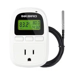
PROGRAMMABLE
TEMPERATURE
Controller Manual
Equivalent to ITC-310T-B
Temperature Controller Manual
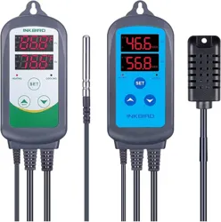
ITC-608T
ITC-608T
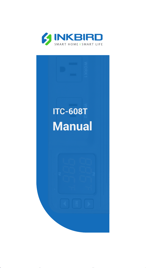
Temperature
Control Mode
ITC-608T + Temperature Probe
2.Quick Guide
1
PAGE
4
Part 1
Part 2 Part 3
Quick Guide to Use
The instruction manual will skip to the corresponding page
according to the probe you select.
Dual Temperature Probes
Control Mode
ITC-608T + Dual Temperature
Probes
DUAL TEMPERATURE
PROBES
Controller Manual
ITC-608T
Part 4
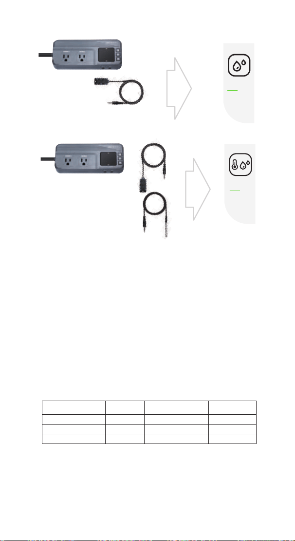
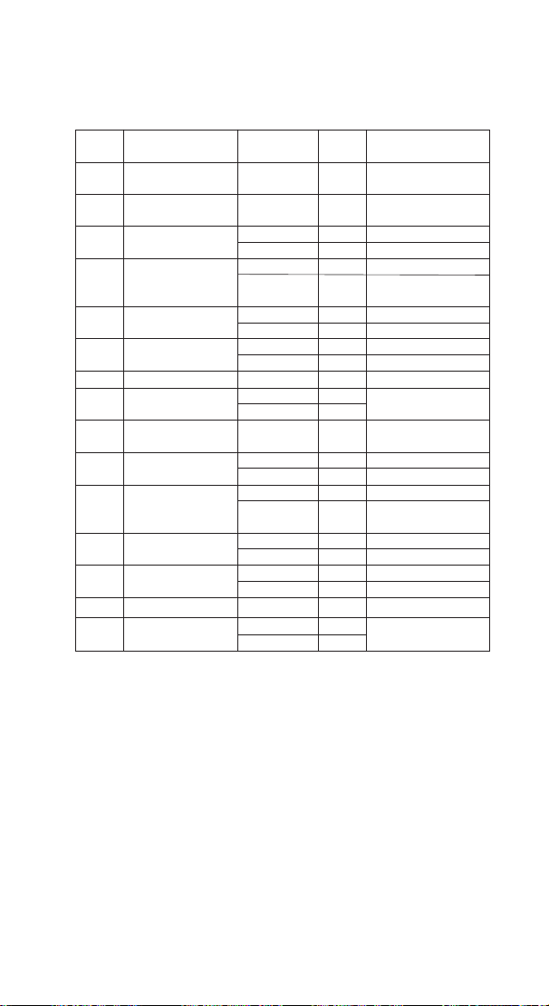
3. Specification
Power
Voltage: 120Vac 60Hz
Current: 15A
Wattage: 1800W
Temperature Probe (optional)
Type of temperature probe:R25°C=100KΩ±1%,
R0°C=26.74~27.83KΩ , B25/85°C=3435K±1%
Temperature measurement range:-40°C~100°C/-40°F~212°F
Temperature display accuracy:0.1°C/°F(<100°C/°F),
1°C/°F(>=100°C/°F)
Temperature measurement accuracy:
Range of Temperature
Celsius
Celsius Error
Range of Temperature
Fahrenheit
Fahrenheit Error
-40℃≤T<10 ℃ ±2 ℃ -40℉≤T<50 ℉ ±3 ℉
10℃≤T<80 ℃ ±1 ℃ 50℉≤T<176 ℉ ±2℉
80℃≤T≤100 ℃ ±2 ℃ 176℉≤T≤212 ℉ ±3 ℉
Humidity Probe(optional)
Type of humidity probe:HTG3515CH
Relative humidity measurement range:5~99%RH
Humidity display accuracy:0.1%RH
HUMIDITY
Controller Manual
Equivalent to IHC-200
Humidity Controller Manual
ITC-608T
TEMPERATURE
HUMIDITY
Controller Manual
Equivalent to IHC-230
Temperature & Humidity
Controller Manual
ITC-608T
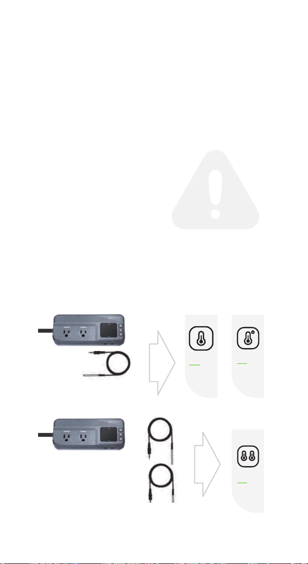
Humidity
Control Mode
ITC-608T + Humidity Probe
Temperature and Humidity
Control Mode
ITC-608T + Temperature Probe
+Humidity Probe
2
Part 5
36
PAGE
43
Part 6
PAGE

4. Technical Assistance and Warranty
4.1 Technical Assistance
If you have any problems installing or using this controller,
please carefully and thoroughly review the instruction
manual. If you require assistance, please write us
to [email protected]. We will reply your emails
in 24 hours from Monday through Saturday.
You can also visit our web site www.ink-bird.com to find the
answers of the common technical questions.
4.2 Warranty
INKBIRD TECH. C.L. warrants this controller for two years
(temperature and humidity probe for one year) from the date
of purchase when operated under normal condition by the
original purchaser (not transferable), against defects caused
by INKBIRD’s workmanship or materials. This warranty is
limited to the repair or replacement, at INKBIRD’s discretion
of all or part of the controller. The original receipt is required
for warranty purposes.
3
Relative humidity measurement accuracy(10%~95%RH):
Typical value±3%RH, Maximum value±5%RH
Display unit:temperature:Celsius °C or Fahrenheit °F;
humidity:%RH
Ambient
Ambient temperature:-20°C~60°C/-4°F~140°F
Storage environment:temperature:0°C~60°C/32°F~140°F;
humidity:20~80%RH(Unfrozen or condensation state )
Warranty
Controller: Two years warranty
Temperature and Humidity Probe: One year warranty
4
TEMPERATURE
Controller Manual
Equivalent to ITC-308
Temperature Controller Manual
ITC-608T
Part 2
5
86.8
f
96.0
f
WORK1 WORK2
A
B C D
E
F
P1 P2
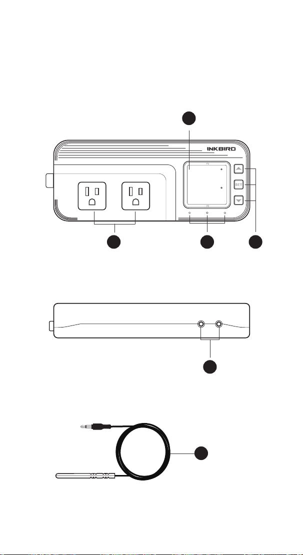
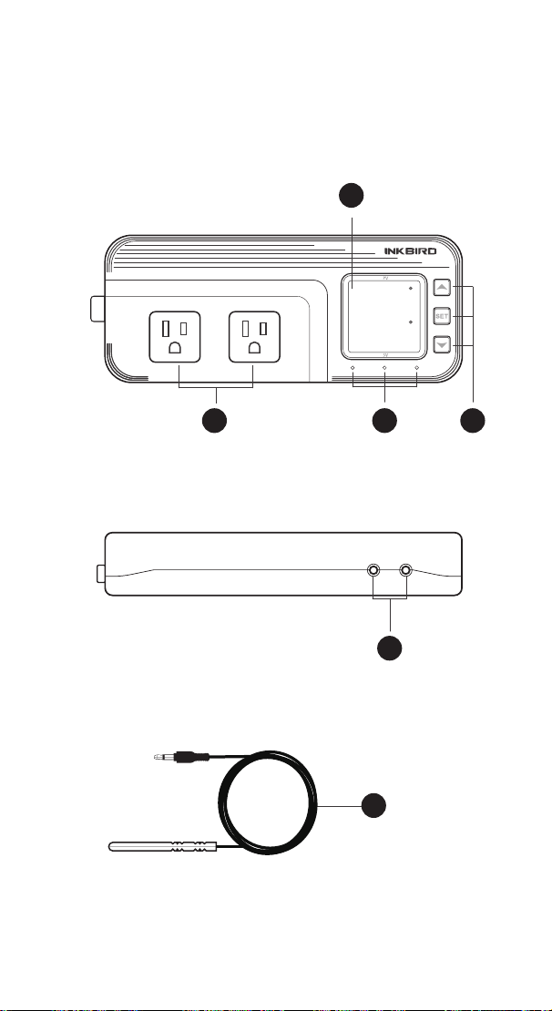
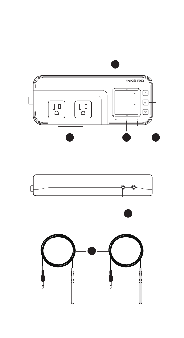
1 Get to Know the Controller

6
Functions on screen
PV:
In normal mode, the measured temperature is displayed.
In settings mode, it will display menu code.
SV:In normal mode, the temperature setting value is
displayed. In setting mode, it will display the setting value.
Output(WORK1/WORK2) Instruction
WORK1:
The heating output
WORK2: The cooling output
Indicator LED:
●Red LED is on WORK1 output is on.
●Green LED is on WORK2 output is on.
●Green LED is blinking WORK2 output is performing the
function of compressor delay.
●Yellow LED is on The controller is in the setting mode.
Button Instruction
Please read the detail on 2.Button Operation Instructions below.
Probe interface
Temperature probe can be insert into P1 or P2 interface.
Temperature probe
If the controller display Er, you may get a false temperature
probe, please try harder to insert the probe and rotate it to
make good contact. If the problem is still persists, it is likely the
internal probe wire has been damaged by the moisture or heat
temperature.
The probe and cable cannot be touched by the flame.
Do not exceed the probe temperature range to avoid
damaging.
A
B
D
E
F
C

7
2 Button Operation Instructions
2.1 Restore Default Settings
Press the “ " button to power on, the buzzer will make a
short call, indicating that all parameters of the user's
temperature probe function return to the default setting value.
2.2 “ ” and “ ”Button Function in Normal Operation
Mode
Press “ ", PV shows HD, SV shows heating difference value;
press “ ", PV shows CD, SV shows cooling difference value,
and It will be back to the normal display if there is no
operation for 3 seconds or pressing the "SET" button.
2.3 “SET” Button Function in Normal Operation Mode
Short press the “SET” button to enter the quick setting
temperature value mode. SV shows the temperature setting
value and flashes, and short press “ ” or “ ” button to
increase or decrease the setting value, long press “ ” or
“ ”button to quickly increase or decrease the setting value,
finally press the “
SET" button again to confirm and exit. If
there is no operation, it will automatically exit after 10
seconds and save the setting value.
2.4 Button Function in Setting Mode
When the controller is working normally, press the “SET”
button for 2 seconds to enter the setting mode, the PV screen
shows the first menu code “
TS” and the SV shows the
corresponding setting value. Press “
SET” button to scroll
down the menu item and save the parameters of the previous
menu item. Press “ ” or “ ”button to change the current
setting value. If in the setting state, there is no button
operation within 30 seconds or long press “
SET" button for 2
seconds, exit and save the setting state, return to normal
operation mode.
8
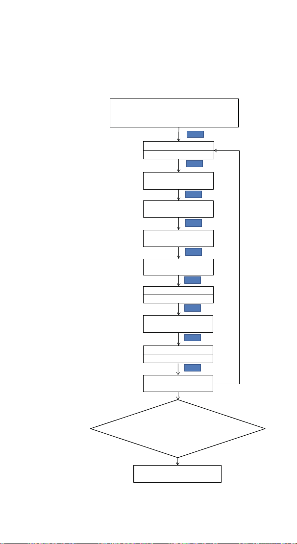
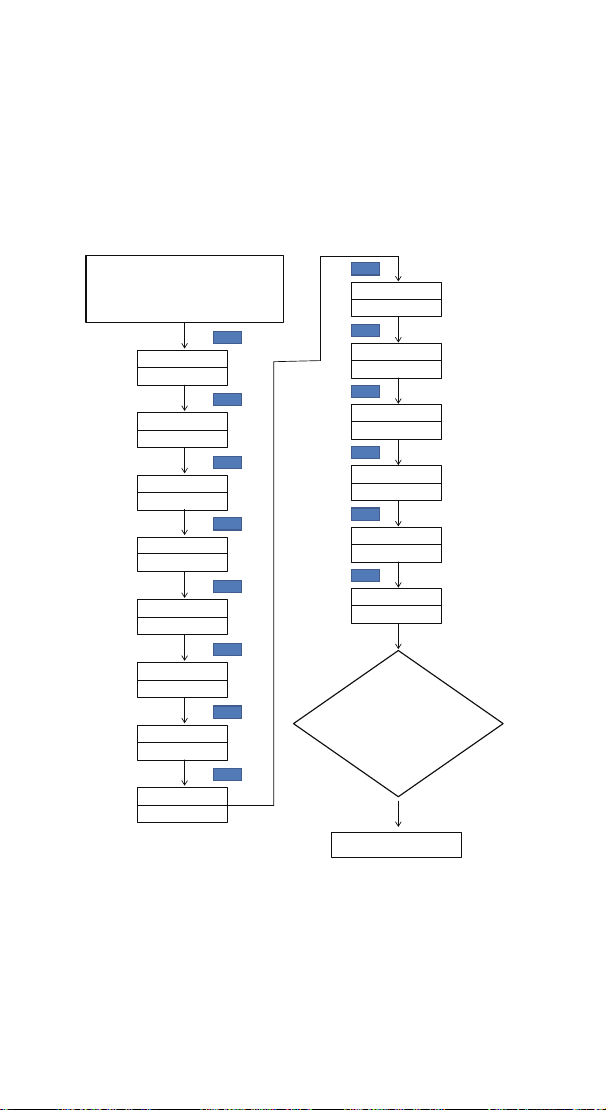
3 Menu Instruction
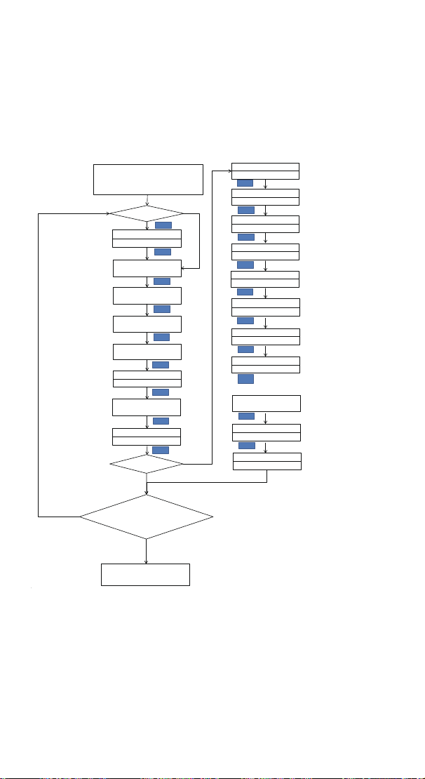
3.1 Setting mode Flow Chart
Temperature Setting Value
Heating difference value
Cooling difference value
SET
Alarm High Temperature Limit
Alarm Low Temperature Limit
Compressor Delay Time
Temperature Calibration
Temperature Unit
Press "SET" Key for over 2
seconds to enter parameters
setting mode
TS
77.0℉
HD
CD
AH
AL
PT
0Minute
CF
F
CA
No Key for 30 seconds or
Presss "SET" key for over 2
second ?
Working normally
SET
SET
SET
SET
SET
SET
SET
SET
SET
TR=0

9
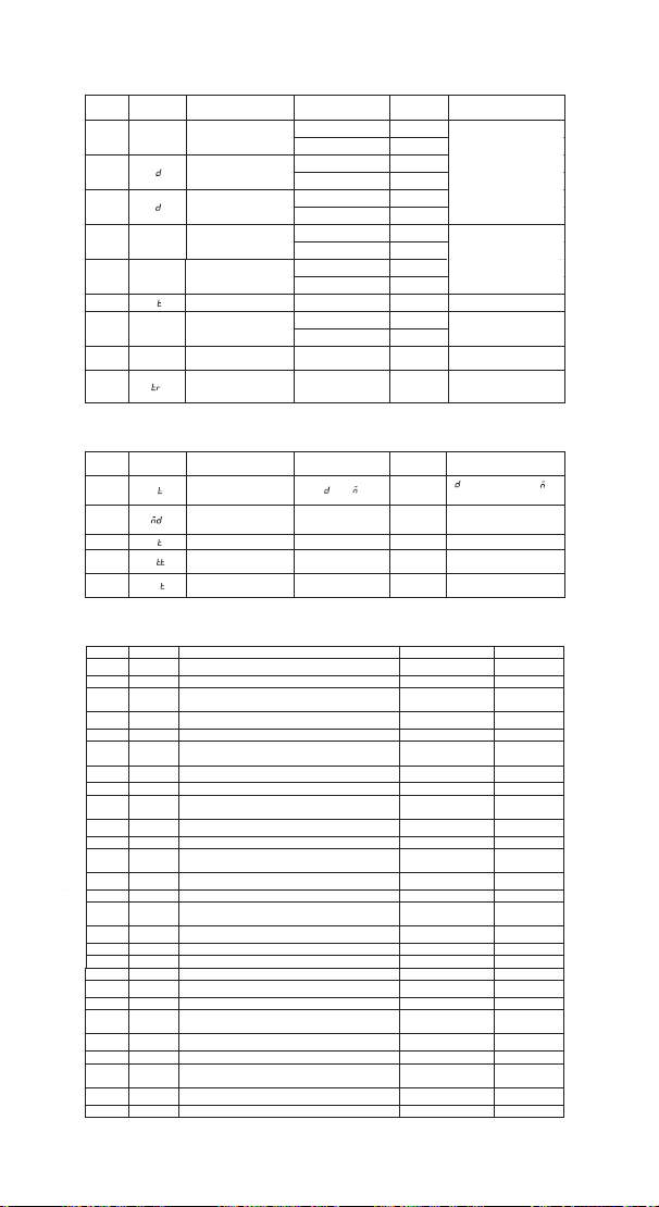
3.2 Setting Menu Instruction
Code Symbol Function Setting Range
Default
Settings
Annotation
TS tS
Temperature Setting
Value
-40.0℃~100℃
25.0
℃
-40.0℉~212℉ 77.0 ℉
℉
HD
Heating Difference
Value
0.3℃~15.0℃ 2.0 ℃
1.0℉~30.0℉ 3.0 ℉
℉
CD
Cooling Difference
Value
0.3℃~15.0℃ 2.0 ℃
1.0
℉
~30.0
℉
3.0
℉
AH AH
Alarm High
Temperature Value
-40.0
℃~
100
℃
100
℃
-40.0℉~212℉
212
℉
℉
AL AL
Alarm Low
Temperature Value
-40.0℃~100℃ - 40.0 ℃
-40.0℉~212℉ - 40.0 ℉
PT
C
ompressor Delay
0 ~10 minutes
0 minute More details on 4.3
More details on
4
.
More details on 4.1
CA CA
Temperature
Calibration
-9.9 ℃~ 9.9 ℃ 0.0 ℃
More details on 4.4
-
15.0
℉
~15.0
℉
0.0
℉
CF CF
Fahrenheit or
Celsius
Setting
C or F F More details on 4.5
TR Timer Setting
0 、1 or 2
0 More details on 4.6
4 Control Function Instruction
When the controller works normally, the PV shows the
measured temperature, meantime the SV screen shows the
temperature setting value, and automatically recognizes and
converts for the heating or cooling working mode , in which
WORK1 is the heating output, furthermore the red led is the
WORK1 heating output status indicator;WORK2 is cooling
output, furthermore the green led is WORK2 cooling output
status indicator.
4.1 Instructions for Setting Temperature Control (TS,HD,CD)
4.1.1 Normal Temperature Control:
When the measured temperature PV ≤ TS(Temperature Setting
Value) – HD(Heating difference value),the controller will enter
the heating state, the red led is on, WORK1 output works.
When the measured temperature PV ≥ TS(Temperature Setting
Value), the red led is off and the WORK1 output turns off.
When the measured temperature PV ≥ TS(Temperature Setting
Value) + CD(Cooling difference value), the controller will enter
the cooling state, the green led is on, WORK2 output works;
the green led flashes, indicating that the cooling device is in
the state of the Compressor delay protection. When
PV(measured temperature) ≤ TS(temperature setting value),
H
C
P
.2

10
the green led is off and the WORK2 output turns off.
For example, setting TS=25.0°C, CD=2.0°C, HD=3.0°C, when
the measured temperature value ≤ 22°C (TS-HD), the
controller will enter the heating state; when the measured
temperature value ≥ 25°C, the heating will stop; when the
measured temperature value ≥27.0°C(TS+CD),the controller
enter the cooling state; when measured temperature value ≤
25.0°C, cooling will stop.
4.1.2 Special Temperature Control
There is no need to judge the difference value in heating or
cooling when power on or exiting the setting state, it directly
compare with TS(temperature setting value).
For example: When power on or exiting the setting state,
TS=25.0°C, CD=2.0°C, HD=3.0°C. If PV( measured temperature
value) >25.0°C, it enters the cooling state. When PV(measured
temperature value) ≤25.0°C, the cooling stops. Then return to
normal temperature control. When PV(measured temperature
value) <25.0 °C, it enter the heating state, when PV(measured
temperature value) ≥ 25.0 °C, heating stops, and then return to
normal temperature control.
4.2 Alarm High / Low Temperature Limit Settings(AH,AL)
When measured temperature ≥ AH, high temperature limit
alarm, then will turn off heating and cooling output, PV shows
alternate AH with current temperature, buzzer will “bi-bi-Biii”
alarm, until the temperature <AH, buzzer off and return to
normal display and control. Or press any button to turn the
buzzer alarm off only.
When measured temperature ≤ AL, low temperature limit
alarm, then will turn off heating and cooling output, PV shows
alternate AL with current temperature, buzzer will “bi-bi-Biii”
alarm, until the temperature >AL, buzzer off and return to
normal display and control. Or press any button to turn the
buzzer alarm off only.

11
4.3 Compressor Delay Time(PT)
In the cooling mode, when the power is turned on for the first
time, PV(measured temperature value) ≥ TS(Temperature
setting value) + CD(Cooling difference value), it will not start
cooling immediately, but waiting for a delay time(PT).
When two adjacent of cooling starting intervals are greater
than the delay time, it will immediately start cooling; When two
adjacent of cooling starting intervals are less than the delay
time, it needs to operate the remaining delay time to start the
cooling.
Delay time will start counting from the cooling output off.
4.4 Temperature Calibration(CA)
When the measured temperature deviates from the standard
temperature, the temperature calibration function can be used
to make the measured value of the instrument consistent with
the standard value. The calibrated temperature=the measured
temperature + the calibration value.
4.5 Fahrenheit or Celsius Settings (CF)
The users can set the display unit to Fahrenheit or Celsius
according to their habits. The default temperature is
Fahrenheit. If you need to display the unit in Celsius, then set
the CF to C. Please note that when the CF changes state, all
setting values are restored to the default setting and the
buzzer gives a short beeping prompt.
4.6 Timer Setting (TR)
TR
is the parameter for whether the timer function is enabled.
0 is off and 1 or 2 is on. If user set TR=1 or 2,please see
Part 3
12
PROGRAMMABLE
TEMPERATURE
Controller Manual
Equivalent to ITC-310T-B
Temperature Controller Manual
ITC-608T
Part 3
13
86.8
f
96.0
f
WORK1 WORK2
A
B C D
E
F
P1 P2
1 Get to Know the Controller

14
Functions on screen
PV:
In normal mode, the measured temperature is
displayed. In settings mode, it will display menu code.
SV:In normal mode, the temperature setting value is
displayed. In setting mode, it will display the setting value.
Output(WORK1/WORK2) Instruction
WORK1:
The heating output
WORK2: The cooling output
Indicator LED
●Red LED is on WORK1 output is on.
●Green LED is on WORK2 output is on.
●Green LED is blinking WORK2 output is performing the
function of compressor delay.
●Yellow LED is on The controller is in the setting mode.
Button Instruction
Please read the detail on 2.Button Operation Instructions
below.
Probe interface
Temperature probe can be insert into P1 or P2 interface.
Temperature probe
If the controller display Er, you may get a false temperature
probe, please try harder to insert the probe and rotate it to
make good contact. If the problem is still persists, it is likely
the internal probe wire has been damaged by the moisture or
heat temperature.
The probe and cable cannot be touched by the flame.
Do not exceed the probe temperature range to avoid
damaging.
.
A
B
D
E
F
C

15
2 Button Operation Instructions
2.1 Restore Default Settings
Press the " " button to power on, the buzzer will make a
short call, indicating that all parameters of the user's
temperature probe function return to the default setting
value.
2.2 Start Controlling Temperature from the First Stage
Forcibly
When TR=1 or 2, press the increase button “ ”to power on,
the buzzer will make a short call, indicating the user that
will start controlling temperature from the first stage
forcibly.
2.3 “ ”and“ ”Button Function in Normal Operation
Mode
2.3.1 When TR=0
Press “ ”, PV shows HD, SV shows heating difference
value. Press “ ”,PV shows CD,SV shows cooling
difference value.
2.3.2 When TR=1 or 2
Press “ ”PV shows current time unit, SV shows the
current remaining working time; And It will be back to the
normal display if there is no operation for 3 seconds or
pressing the "SET" button. Press “ ”,PV shows the
current stage,SV shows the setting value of current stage.
And It will be back to the normal display if there is no
operation for 3 seconds or pressing the "SET" button.
2.3.3 When TR=1 or 2
press “ ”and“ ” simultaneously for one second, it will
start operating from the SST setting forcibly,at the same
time, the buzzer will give a short beeping prompt.
2.4 “SET” Button Function in Normal Operation Mode
Short press the “SET” button to enter the quick setting
temperature value mode. When TR=0, SV displays the
temperature setting value and flashes. Short Press “ ” or
“ ” button to increase or decrease the temperature
setting value. Long Press“ ”or“ ”button to quickly

16
increase or decrease the temperature setting value, then press
"
SET" button to confirm and exit. When TR=1 or 2,SV shows
the temperature setting value and flashes, then short press
“ ” or “ ” button to increase or decrease the temperature
setting value. Long press the“ ” or “ ”button to increase or
decrease the temperature setting value quickly. Press the
"
SET" button to switch to the current stage control duration
value. Short press the “ ”or “ ” button to change the
current stage control duration value. Press the “
SET" button to
switch to whether to alarm after the completion of the current
stage, then press “ ” or “ ” to modify the setting value .
Press “
SET” button again to confirm and exit. If there is no
operation for 3 seconds ,It will automatically exit after 10
seconds and save the setting value.
2.5 Button Function in Setting Mode
When the controller is working normally, press the “SET”
button for 2 seconds to enter the setting mode. The PV shows
the first menu code “
TS”, if TR=1 or 2, the PV shows the
second menu code“
HD”, SV shows the corresponding setting
value. Press “
SET” button to scroll down the menu item and
save the parameters of the previous menu item. Press “ ” or
“ ” button to change the current setting value. If in the
setting state, there is no operation within 30 seconds or long
press "SET" button for 2 seconds, it will exit and save the
setting state and return to normal operation mode.
17
……
3 Menu Instruction
3.1 Menu Setting Flow Chart
Time Unit: D(Day),
H(Hour)or M(Minute)
Cycle Mode 1~999,
MD=0 Infinite Cycle
N
Y
After the power off,
re - running
mode: 0-> manual,
1-> automatic
Temperature Setting Value
Stage Value 1~12
Heating difference value
Start Stage Value
Cooling difference value
Stage1:Temperature
Setting Value
SET
Alarm High
Temperature Limit
Stage1:Duration Length
Alarm Low
Temperature Limit
Stage1:User Defined Alert
at the end of stage1
The Qty of stages depend
on the STT Value
Compressor Delay Time
Stage12:Temperature Set Value
Temperature Calibration
Stage12:Duration Length
Temperature Unit
Stage12:User Defined
Alert
at the end of stage12
Y
U1~U12:
N
n:No Alert
A:Alert
C:Confirm
S:Stop Program
TR=0:Simple Mode
TR=1:Continious Timer Mode
TR=2:Target Timer Mode
Press "SET" Key for over 2
seconds to enter parameters
setting mode
TR = 0 ?
TS
77.0℉
HD
CD
AH
AL
PT
0Minute
CF
F
CA
TR = 1or TR=2
?
UT
M
MD
1
AT
0
STT
1
SST
1
S01
77.0℉
H01
10
U01
n
S12
H12
10
U12
n
No Key for 30 seconds or
Presss "SET" key for over 2
second ?
SET
SET
SET
SET
SET
SET
SET
SET
SET
SET
SET
SET
SET
SET
SET
SET
SET
SET
SET
Working normally
18
3.2 Setting Menu Instruction
Code Symbol Function Setting Range
Default
Settings
Annotation
TS tS
Temperature Setting
Value
-40.0℃~100℃
25.0℃
-40.0
℉
~212
℉
77.0
℉
℉
HD H
Heating Difference
Value
0.3℃~15.0℃ 2.0℃
1.0℉~30.0℉ 3.0℉
℉
CD C
Cooling Difference
Value
0.3℃~15.0℃ 2.0℃
1.0℉~30.0℉
3.0℉
AH AH
Alarm High
Temperature Value
-40.0
℃~
100
℃
100
℃
-40.0
℉
~212
℉
212
℉
℉
3.2.1 When TR=1 or 2, menu code setting is as below.
Code Symbol Function Setting Range
Default
Settings
Annotation
UT U
Time Unit Setting
Value
D
:Day, :Hour, :
Minute
MD Cycle Setting Value 0-999 1
When is 00
,
infinite
loop
AT
A
Auto or Manual Mode
0 or 1
0
0:Manually, 1:Automatic
STT S
Time Stage Setting
Value
1-12 1 More details on 4.6.4
SST SS
Start Stage Settings
Value
1~12 1 More details on 4.6.5
3
.
2.2
When STA is set to 12, menu code setting is as below.
Code
Symbol
Function
Default Settings
Annotation
S01 S01 Stage 1 Temperature Setting Value 25.0℃ or 77.0℉ *
H01
H01
Stage 1 Control Duration Value
10
**
U01 U01
Whether to Alarm after the Completion of
Stage1
n ***
S02 S02 Stage 2 Temperature Setting Value
25.0℃ or 77.0℉
*
H02
H02
Stage 2 Control Duration Value
10
**
U02 U02
Whether to Alarm after the Completion of Stage
2
n ***
S03
S03
Stage 3 Temperature Setting Value
25.0℃ or 77.0℉
*
H03
H03
Stage 3 Control Duration Value
10
**
U03 U03
Whether to Alarm after the Completion of Stage
3
n ***
S04
S04
Stage 4 Temperature Setting Value
25.0℃ or 77.0℉
*
H04
H04
Stage 4 Control Duration Value
10
**
U04 U04
Whether to Alarm after the Completion of Stage
4
n ***
S05
S05
Stage 5 Temperature Setting Value
25.0
℃or
77.0
℉
*
H05
H05
Stage 5 Control Duration Value
10
**
U05 U05
Whether to Alarm after the Completion of Stage
5
n ***
S06 S06 Stage 6 Temperature Setting Value
25.0℃ or 77.0℉
*
H06
H06
Stage 6 Control Duration Value
10
**
U06
U06
Whether to Alarm after the Completion of Stage
n
***
AL AL
Alarm Low
Temperature Value
-40.0℃~100℃ -40.0℃
-40.0℉~212℉ -40.0℉
PT P Compressor Delay
0~10 minutes
0 minute More details on 4.3
CA CA
Temperature
Calibration
-9.9℃~9.9℃ 0.0℃
More details on 4.4
More details on 4.1
More details on 4.2
-15.0
℉
~15.0
℉
0.0
℉
CF CF
Fahrenheit or Celsius
Setting
C or F F More details on 4.5
TR Timer Setting
0、1 or 2
0 More details on 4.6.2
6
S07
S07
Stage 7 Temperature Setting Value
25.0℃ or 77.0℉
*
H07
H07
Stage7 Control Duration Value
10
**
U07 U07
Whether to Alarm after the Completion of Stage
7
n ***
S08
S08
Stage 8 Temperature Setting Value
25.0℃ or 77.0℉
*
H08
H08
Stage 8 Control Duration Value
10
**
U08 U08
Whether to Alarm after the Completion of Stage
8
n ***
S09
S09
Stage 9 Temperature Setting Value
25.0
℃
or 77.0
℉
*
H09
H09
Stage 9 Control Duration Value
10
**
H
H

19
U09 U09
Whether to Alarm after the Completion of Stage
9
n ***
S10
S10
Stage 10 Temperature Setting Value
25.0
℃
or 77.0
℉
*
H10
H10
Stage 10 Control Duration Value
10
**
U10 U10
Whether to Alarm after the Completion of Stage
10
n ***
S11
S11
Stage 11 Temperature Setting Value
25.0
℃
or 77.0
℉
*
H11
H11
Stage 11 Control Duration Value
10
**
U11 U11
Whether to Alarm after the Completion of Stage
11
n ***
S12
S12
Stage 12 Temperature Setting Value
25.0
℃
or 77.0
℉
*
H12
H12
Stage 12 Control Duration Value
10
**
U12 U12
Whether to Alarm after the Completion of Stage
12
n ***
* The setting value range is the same as TS
** More details on 4.6.7
*** More details on 4.6.8
4. Control Function Instruction
When the controller works normally, the PV shows the
measured temperature, meantime the SV screen shows the
temperature setting value, and automatically recognizes and
converts for the heating or cooling working mode , in which
WORK1 is the heating output, furthermore the red led is the
WORK1 heating output status indicator;WORK2 is cooling
output, furthermore the green led is WORK2 cooling output
status indicator.
4.1 Instructions for Setting Temperature Control
(TS,HD,CD,S01~S12)
4.1.1 TR=0, Temperature Control Mode
4.1.1.1 Normal Temperature Control
When the measured temperature PV ≤ TS(Temperature Setting
Value) – HD(Heating difference value),the controller will enter
the heating state, the red led is on, WORK1 output works.
When the measured temperature PV ≥ TS(Temperature Setting
Value), the red led is off and the WORK1 output turns off.
When the measured temperature PV ≥ TS(Temperature Setting
Value) + CD(Cooling difference value), the controller will enter
the cooling state, the green led is on, WORK2 output works;
the green led flashes, indicating that the cooling device is in
the state of the compressor delay protection. When
PV(measured temperature) ≤ TS(temperature setting value),
the green led is off and the WORK2 output turns off.

20
For example, setting TS=25.0°C, CD=2.0°C, HD=3.0°C, when
the measured temperature value ≤ 22°C (TS-HD), the
controller will enter the heating state; when the measured
temperature value ≥ 25°C, the heating will stop; when the
measured temperature value ≥27.0°C(TS+CD),the controller
enter the cooling state; when measured temperature value ≤
25.0°C, cooling will stop;
4.1.1.2 Special Temperature Control
When TR=0, there is no need to judge the difference value in
heating or cooling when power on or exiting the setting state,
it directly compare with TS(temperature setting value).
For example: When power on or exiting the setting state,
TS=25.0°C, CD=2.0°C, HD=3.0°C. If PV( measured temperature
value) >25.0°C, it enters the cooling state. When PV(measured
temperature value) ≤25.0°C, the cooling stops. Then return to
normal temperature control. When PV(measured temperature
value) <25.0 °C, it enter the heating state, when PV(measured
temperature value) ≥ 25.0 °C, heating stops, and then return to
normal temperature control.
4.1.2 When TR=1 or 2, Timer Mode
The TS(temperature setting value) will be invalid. The
controller will execute commands according to the setting
values of S01~S12, the setting value of H01~H12, and the
setting value of U01~U12.
About how to set the time and control temperature, please
refer to 6.6
4.2 Alarm High / Low Temperature Limit Settings (AH,AL)
When measured temperature ≥ AH, high temperature limit
alarm, PV shows alternate AH with current temperature,
buzzer will “bi-bi-Biii” alarm, until the temperature <AH, buzzer
off and return to normal display and control. Or press any
button to turn the buzzer alarm off only.
When measured temperature ≤ AL, low temperature limit
alarm, PV shows alternate AL with current temperature, buzzer
will “bi-bi-Biii” alarm, until the temperature >AL, buzzer off and

21
return to normal display and control. Or press any button to
turn the buzzer alarm off only.
4.3 Compressor Delay Time(PT)
In the cooling mode, when the power is turned on for the first
time, PV(measured temperature value) ≥ TS(Temperature
setting value) + CD(Cooling difference value), it will not start
cooling immediately, but waiting for a delay time(PT).
When two adjacent of cooling starting intervals are greater
than the delay time, it will immediately start cooling; When two
adjacent of cooling starting intervals are less than the delay
time, it needs to operate the remaining delay time to start the
cooling.
Delay time will start counting from the cooling output off.
4.4 Temperature Calibration(CA)
When the measured temperature deviates from the standard
temperature, the temperature calibration function can be used
to make the measured value of the instrument consistent with
the standard value. The calibrated temperature=the measured
temperature + the calibration value.
4.5 Fahrenheit or Celsius Settings (CF)
The users can set the display unit to Fahrenheit or Celsius
according to their habits. The default temperature is
Fahrenheit. If you need to display the unit in Celsius, then set
the CF to C. Please note that when the CF changes state, all
setting values are restored to the default setting and the
buzzer gives a short beeping prompt.
4.6 Time-Temperature Setting Values Execution Cycle
Times MD and Time-Temperature Parameter Settings
(TR,UT,STT,SST,S01~S12,H01~H12,U01~U12)
4.6.1 MD
is the execution times of the time-temperature
setting value. From the SST setting value to the last stage
setting value of STT, it is a cycle. If MD=0 represents an
infinite loop, MD=1~999 represents the specific times of cycle
execution. The default value of MD is 1. Under the condition of
MD=1~999, after the corresponding execution cycles is
22
completed, the detailed status is described in 6.4.6.8.
4.6.2 TR is the parameter for whether the timer function is
enabled. 0 is off and 1 or 2 is on.
4.6.2.1 TR=0,Temperature Control Mode The timer function
will not start, all the setting parameters after the parameter TR
will not shows in the menu, and there is no need to set.
4.6.2.2 TR=1 Continuous Timer Mode & TR=2 Target Timer
Mode
The user is required to set the time and corresponding
temperature control parameters, at this time, TS(temperature
setting value) will be invalid, the system will control according
to the temperature of the time period.
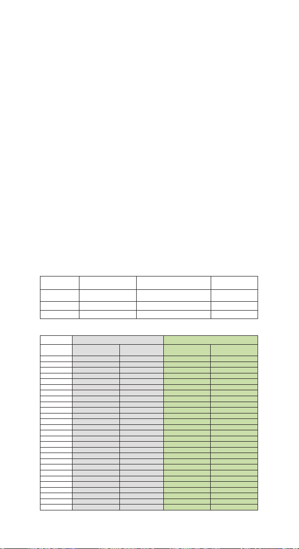
Regarding the difference between TR=1(Continuous Timer
Mode) and TR=2(Target Timer Mode), the following table
illustrates their differences in details.
Stage
X(N=1~12)
STX(X=1~12)( ℃)
HTX(X=1~12)(Minutes)
UAX(X=1~12)
Stage1
20.0
10
n
Stage2
30.0
7
n
Stage3
35.0
12
n
Different reaction times are obtained, as shown in the following table
:
TR = 1 Continuous Timer mode TR = 2 Target Timer mode
Time
[minutes]
Temp[°C] Stage Temp[°C] Stage
0
10
1
10
1
12
1
12
2
14
1
14
3
16
1
16
4
18
1
18
5
20
1
20
1
6
20
1
20
1
7
20
1
20
1
8
20
1
20
1
9
20
1
20
1
10
20
1
20
1
11
22
2
20
1
12
24
2
20
1
13
26
2
20
1
14
28
2
20
1
15
30
2
22
16
30
2
24
17
30
2
26
18
32
3
28
19
34
3
30
2
20
35
3
30
2
21
35
3
30
2
22
35
3
30
2
23
35
3
30
2
24
35
3
30
2
25
35
3
30
2
26
35
3
32

23
27
35
3
34
28
35
3
35
3
29
35
3
35
3
30
35
3
31
35
3
32
35
3
33
35
3
34
35
3
35
35
3
36
35
3
37
35
3
38
35
3
39
35
3
The above table is the difference between the continuous timer mode and the
target timer mode of the thermostat, which is represented by the curve image
as follows:
0
5
10
15
20
25
30
35
40
0 1 2 3 4 5 6 7 8 9 101112131415161718192021222324252627 2829303132333435363738394041
erutarepmeT
Time [min]
Timer mode CS
Continuous vs. Target mode
CS = C
CS = T
From the graph, we can see that when TR=1, the continuous
timer mode (the blue line),the stage control time H01~H03 is
continuous time, 0...10,11...17,18...29, total is 29 minutes;
When TR=2, the target timer mode (the red line),the stage
control time H01~H03 is only started when the current
temperature reaches the setting temperature of the current
stage, such as 5...14, 19...25, 32...35, and total is 39 minutes.
4.6.3 UT is a time unit setting parameter, and the user can set
the time unit to days, hours or minutes as required;
4.6.4 STT is the setting stages of the time – temperature
period. Users can set different time periods to control different
temperature according to their needs. At most 12 time periods
can be set to control 12 different temperature.
4.6.5 SST is the beginning stage of time - temperature
period. Users can select which stage to start control
according to their own requirements.
4.6.6 S01~S12 are temperature setting parameters. When
TR=1 or 2, the setting value of ST1~ST12 will replace the TS
value as the condition parameter of temperature control;
4.6.7 H01~H12 are duration parameters, and the current
Output(WORK1/WORK2) Instruction
WORK1: The P1 heating/cooling output
WORK2: The P2 heating/cooling output
Indicator LED:
●Red LED is on WORK1 output is on.
●Red LED is blinking WORK1 output is performing the
function of compressor delay.
●Green LED is on WORK2 output is on.
●Green LED is blinking WORK2 output is performing the
function of compressor delay.
●Yellow LED is on The controller is in the setting mode.
Button Instruction
Please read the detail on 2.Button Operation Instructions below
Probe interface
Two temperature probes can be insert into P1 and P2 interface.
Temperature probe
●If the controller display Er, you may get a false temperature
probe, please try harder to insert the probe and rotate it to make
good contact. If the problem is still persists, it is likely the
internal probe wire has been damaged by the moisture or heat
temperature.
●The probe and cable cannot be touched by the flame.
●Do not exceed the probe temperature range to avoid
damaging.
2 Button Operation Instructions
2.1 Restore Default Settings
Press and hold the “ " button to power on, the buzzer will
make a short call, indicating that all parameters of the user's
temperature and humidity probe function return to the default
setting value.
2.2 “ ” and “ ”Button Function in Normal Operation
Mode
Press the “ ", PV shows the current temperature setting
value , SV shows current humidification value; press “ ", PV
shows current temperature value, SV the current humidification
setting value , and It will be back to the normal display if there is
no operation for 3 seconds orpressing the "
SET" button.
2.3 “SET” Button Function in Normal Operation Mode
Short press the “
SET” button to enter the quick setting
temperature and humidity value mode. PV shows the current
temperature setting value and flashes, and short press “ ” or
“ ” button to increase or decrease the setting value, long
press “ ” or “ ”button to quickly increase or decrease the
setting value, Short press the “
SET” button again,SV shows
the current humidity setting value and flashes, and short press
“ ” or “ ” button to increase or decrease the setting value,
long press “ ” or “ ”button to quickly increase or decrease
the setting value and lastly press the "
SET" button again to
confirm and exit. If there is no operation, it will automatically
exit after 10 seconds and save the setting value.
2.4 Button Function in Setting Mode
When the controller is working normally, press the “SET” button
for 2 seconds to enter the setting mode,the PV shows the first
menu code“
”, SV shows the corresponding setting value.
Press “
SET” button to scroll down the menu item and save the
parameters of the previous menu item. Press“ ” or
“ ”button to change the current setting value. Selected T to
enter the temperature parameter modification mode; selected H
to enter the humidity parameter modification mode. If in the
setting state, there is no operation within 30 seconds or long
press "
SET" button for 2 seconds, it will exit and save the
setting state and return to normal operation mode.

24
stage will not enter the next time-temperature control until the
current stage is completed.
4.6.8 U01~U12 are the parameters for the user to determine
whether to alarm or not, setting to n=No Alarm; A= Alarm; C=
Confirm; S=Stop Program.
4.6.8.1 UX=n: If the current stage is set to n, the next cycle
control is entered; if the execution of the cycle index MD is
completed, all output controls are turned off, PV shows the
current temperature, and SV shows End.
4.6.8.2 UX=A:If the current stage is set to A, when the
duration is completed, enter the next stage of control, PV
shows the previous stage UX (X = 01~12), SV shows A, and PV
shows the current temperature, SV shows the current stage of
setting temperature with 1Hz frequency alternate, buzzer
beeps every two seconds; if the cycle index MD is completed,
all output control is turned off, PV shows previous stage UX
(X=01~12), SV shows A and PV shows current temperature,
SV shows End with 1Hz frequency alternately . Press any
button at this time to cancel the buzzer alarm and return to
normal display. If the cycle index MD is completed, PV will
show the current temperature and SV will show End.
4.6.8.3 UX=C:If the current stage is set to C, when the
duration is completed, it still control according to the current
stage of the set temperature, PV shows the current stage UX
(X = 01 ~ 12), SV shows C, and PV shows the current
temperature, SV shows the current stage temperature setting
value with 1Hz frequency alternately . The buzzer beeps every
two seconds. Only when the user presses any button will turn
the alarm off and the control will be entered in the next stage.
If the execution of the cycle index MD is completed, PV shows
the current temperature and SV shows End.
4.6.8.4 UX=S:If the current stage is set to S, when the
duration is completed, all output controls are turned off, PV
shows the current stage UX (X=01~12), S shows down, and
PV shows the current temperature, SV shows the current
stage temperature setting value with 1Hz frequency
alternately, the buzzer beeps every two seconds. Only when
the user presses any button will turn the alarm off and the
Output(WORK1/WORK2) Instruction
WORK1: The P1 heating/cooling output
WORK2: The P2 heating/cooling output
Indicator LED:
●Red LED is on WORK1 output is on.
●Red LED is blinking WORK1 output is performing the
function of compressor delay.
●Green LED is on WORK2 output is on.
●Green LED is blinking WORK2 output is performing the
function of compressor delay.
●Yellow LED is on The controller is in the setting mode.
Button Instruction
Please read the detail on 2.Button Operation Instructions below
Probe interface
Two temperature probes can be insert into P1 and P2 interface.
Temperature probe
●If the controller display Er, you may get a false temperature
probe, please try harder to insert the probe and rotate it to make
good contact. If the problem is still persists, it is likely the
internal probe wire has been damaged by the moisture or heat
temperature.
●The probe and cable cannot be touched by the flame.
●Do not exceed the probe temperature range to avoid
damaging.
2 Button Operation Instructions
2.1 Restore Default Settings
Press and hold the “ " button to power on, the buzzer will
make a short call, indicating that all parameters of the user's
temperature and humidity probe function return to the default
setting value.
2.2 “ ” and “ ”Button Function in Normal Operation
Mode
Press the “ ", PV shows the current temperature setting
value , SV shows current humidification value; press “ ", PV
shows current temperature value, SV the current humidification
setting value , and It will be back to the normal display if there is
no operation for 3 seconds orpressing the "
SET" button.
2.3 “SET” Button Function in Normal Operation Mode
Short press the “
SET” button to enter the quick setting
temperature and humidity value mode. PV shows the current
temperature setting value and flashes, and short press “ ” or
“ ” button to increase or decrease the setting value, long
press “ ” or “ ”button to quickly increase or decrease the
setting value, Short press the “
SET” button again,SV shows
the current humidity setting value and flashes, and short press
“ ” or “ ” button to increase or decrease the setting value,
long press “ ” or “ ”button to quickly increase or decrease
the setting value and lastly press the "
SET" button again to
confirm and exit. If there is no operation, it will automatically
exit after 10 seconds and save the setting value.
2.4 Button Function in Setting Mode
When the controller is working normally, press the “SET” button
for 2 seconds to enter the setting mode,the PV shows the first
menu code“
”, SV shows the corresponding setting value.
Press “
SET” button to scroll down the menu item and save the
parameters of the previous menu item. Press“ ” or
“ ”button to change the current setting value. Selected T to
enter the temperature parameter modification mode; selected H
to enter the humidity parameter modification mode. If in the
setting state, there is no operation within 30 seconds or long
press "
SET" button for 2 seconds, it will exit and save the
setting state and return to normal operation mode.

25
control will be entered in the next stage. If the execution of the
cycle index MD is completed, PV shows the current tempera-
ture and SV shows End.
4.7 Manual or Automatic Mode ( AT )
AT
is the power on operation mode after power off.
AT=0:Manual Mode, after power off to re-power, the
temperature controller will stop working, PV display flicker,
buzzer will beep every one second, prompting the user to reset
the parameters, after saving and exiting, the temperature
controller restart the work.
AT=1:Automatic Mode,after the power is turned off, the
time still counts. After the power is turned on again, when
TR=1 and UX (X=01~12) is n or A, the temperature controller
will automatically calculate the time from the power off to the
power on and operate to the corresponding stage, according
to the operating time of H01~H12 and the operating state of
the U01~U12. For example TR=1, Stage1 S01=25.0°C,
H01=4H, U01=n, Stage2 S02=30.0°C, H02=6H, U02=A; when
the temperature controller executes stage1 for 2 hours, and
power off for 3 hours, at this point, the temperature controller
will execute 2+3=5 hours by default, and the temperature
controller will execute stage2 with only 5 hour remaining.
Output(WORK1/WORK2) Instruction
WORK1: The P1 heating/cooling output
WORK2: The P2 heating/cooling output
Indicator LED:
●Red LED is on WORK1 output is on.
●Red LED is blinking WORK1 output is performing the
function of compressor delay.
●Green LED is on WORK2 output is on.
●Green LED is blinking WORK2 output is performing the
function of compressor delay.
●Yellow LED is on The controller is in the setting mode.
Button Instruction
Please read the detail on 2.Button Operation Instructions below
Probe interface
Two temperature probes can be insert into P1 and P2 interface.
Temperature probe
●If the controller display Er, you may get a false temperature
probe, please try harder to insert the probe and rotate it to make
good contact. If the problem is still persists, it is likely the
internal probe wire has been damaged by the moisture or heat
temperature.
●The probe and cable cannot be touched by the flame.
●Do not exceed the probe temperature range to avoid
damaging.
2 Button Operation Instructions
2.1 Restore Default Settings
Press and hold the “ " button to power on, the buzzer will
make a short call, indicating that all parameters of the user's
temperature and humidity probe function return to the default
setting value.
2.2 “ ” and “ ”Button Function in Normal Operation
Mode
Press the “ ", PV shows the current temperature setting
value , SV shows current humidification value; press “ ", PV
shows current temperature value, SV the current humidification
setting value , and It will be back to the normal display if there is
no operation for 3 seconds orpressing the "
SET" button.
2.3 “SET” Button Function in Normal Operation Mode
Short press the “
SET” button to enter the quick setting
temperature and humidity value mode. PV shows the current
temperature setting value and flashes, and short press “ ” or
“ ” button to increase or decrease the setting value, long
press “ ” or “ ”button to quickly increase or decrease the
setting value, Short press the “
SET” button again,SV shows
the current humidity setting value and flashes, and short press
“ ” or “ ” button to increase or decrease the setting value,
long press “ ” or “ ”button to quickly increase or decrease
the setting value and lastly press the "
SET" button again to
confirm and exit. If there is no operation, it will automatically
exit after 10 seconds and save the setting value.
2.4 Button Function in Setting Mode
When the controller is working normally, press the “SET” button
for 2 seconds to enter the setting mode,the PV shows the first
menu code“
”, SV shows the corresponding setting value.
Press “
SET” button to scroll down the menu item and save the
parameters of the previous menu item. Press“ ” or
“ ”button to change the current setting value. Selected T to
enter the temperature parameter modification mode; selected H
to enter the humidity parameter modification mode. If in the
setting state, there is no operation within 30 seconds or long
press "
SET" button for 2 seconds, it will exit and save the
setting state and return to normal operation mode.
26
DUAL TEMPERATURE
PROBES
Controller Manual
ITC-608T
Output(WORK1/WORK2) Instruction
WORK1: The P1 heating/cooling output
WORK2: The P2 heating/cooling output
Indicator LED:
●Red LED is on WORK1 output is on.
●Red LED is blinking WORK1 output is performing the
function of compressor delay.
●Green LED is on WORK2 output is on.
●Green LED is blinking WORK2 output is performing the
function of compressor delay.
●Yellow LED is on The controller is in the setting mode.
Button Instruction
Please read the detail on 2.Button Operation Instructions below
Probe interface
Two temperature probes can be insert into P1 and P2 interface.
Temperature probe
●If the controller display Er, you may get a false temperature
probe, please try harder to insert the probe and rotate it to make
good contact. If the problem is still persists, it is likely the
internal probe wire has been damaged by the moisture or heat
temperature.
●The probe and cable cannot be touched by the flame.
●Do not exceed the probe temperature range to avoid
damaging.
2 Button Operation Instructions
2.1 Restore Default Settings
Press and hold the “ " button to power on, the buzzer will
make a short call, indicating that all parameters of the user's
temperature and humidity probe function return to the default
setting value.
2.2 “ ” and “ ”Button Function in Normal Operation
Mode
Press the “ ", PV shows the current temperature setting
value , SV shows current humidification value; press “ ", PV
shows current temperature value, SV the current humidification
setting value , and It will be back to the normal display if there is
no operation for 3 seconds orpressing the "
SET" button.
2.3 “SET” Button Function in Normal Operation Mode
Short press the “
SET” button to enter the quick setting
temperature and humidity value mode. PV shows the current
temperature setting value and flashes, and short press “ ” or
“ ” button to increase or decrease the setting value, long
press “ ” or “ ”button to quickly increase or decrease the
setting value, Short press the “
SET” button again,SV shows
the current humidity setting value and flashes, and short press
“ ” or “ ” button to increase or decrease the setting value,
long press “ ” or “ ”button to quickly increase or decrease
the setting value and lastly press the "
SET" button again to
confirm and exit. If there is no operation, it will automatically
exit after 10 seconds and save the setting value.
2.4 Button Function in Setting Mode
When the controller is working normally, press the “SET” button
for 2 seconds to enter the setting mode,the PV shows the first
menu code“
”, SV shows the corresponding setting value.
Press “
SET” button to scroll down the menu item and save the
parameters of the previous menu item. Press“ ” or
“ ”button to change the current setting value. Selected T to
enter the temperature parameter modification mode; selected H
to enter the humidity parameter modification mode. If in the
setting state, there is no operation within 30 seconds or long
press "
SET" button for 2 seconds, it will exit and save the
setting state and return to normal operation mode.
Part 4
27
Output(WORK1/WORK2) Instruction
WORK1: The P1 heating/cooling output
WORK2: The P2 heating/cooling output
Indicator LED:
●Red LED is on WORK1 output is on.
●Red LED is blinking WORK1 output is performing the
function of compressor delay.
●Green LED is on WORK2 output is on.
●Green LED is blinking WORK2 output is performing the
function of compressor delay.
●Yellow LED is on The controller is in the setting mode.
Button Instruction
Please read the detail on 2.Button Operation Instructions below
Probe interface
Two temperature probes can be insert into P1 and P2 interface.
Temperature probe
●If the controller display Er, you may get a false temperature
probe, please try harder to insert the probe and rotate it to make
good contact. If the problem is still persists, it is likely the
internal probe wire has been damaged by the moisture or heat
temperature.
●The probe and cable cannot be touched by the flame.
●Do not exceed the probe temperature range to avoid
damaging.
2 Button Operation Instructions
2.1 Restore Default Settings
Press and hold the “ " button to power on, the buzzer will
make a short call, indicating that all parameters of the user's
temperature and humidity probe function return to the default
setting value.
2.2 “ ” and “ ”Button Function in Normal Operation
Mode
Press the “ ", PV shows the current temperature setting
value , SV shows current humidification value; press “ ", PV
shows current temperature value, SV the current humidification
setting value , and It will be back to the normal display if there is
no operation for 3 seconds orpressing the "
SET" button.
2.3 “SET” Button Function in Normal Operation Mode
Short press the “
SET” button to enter the quick setting
temperature and humidity value mode. PV shows the current
temperature setting value and flashes, and short press “ ” or
“ ” button to increase or decrease the setting value, long
press “ ” or “ ”button to quickly increase or decrease the
setting value, Short press the “
SET” button again,SV shows
the current humidity setting value and flashes, and short press
“ ” or “ ” button to increase or decrease the setting value,
long press “ ” or “ ”button to quickly increase or decrease
the setting value and lastly press the "
SET" button again to
confirm and exit. If there is no operation, it will automatically
exit after 10 seconds and save the setting value.
2.4 Button Function in Setting Mode
When the controller is working normally, press the “SET” button
for 2 seconds to enter the setting mode,the PV shows the first
menu code“
”, SV shows the corresponding setting value.
Press “
SET” button to scroll down the menu item and save the
parameters of the previous menu item. Press“ ” or
“ ”button to change the current setting value. Selected T to
enter the temperature parameter modification mode; selected H
to enter the humidity parameter modification mode. If in the
setting state, there is no operation within 30 seconds or long
press "
SET" button for 2 seconds, it will exit and save the
setting state and return to normal operation mode.
WORK1 WORK2
A
B C D
E
F
P1 P2
1 Get to Know the Controller
88.6
f
98.6
f

28
Output(WORK1/WORK2) Instruction
WORK1: The P1 heating/cooling output
WORK2: The P2 heating/cooling output
Indicator LED:
●Red LED is on WORK1 output is on.
●Red LED is blinking WORK1 output is performing the
function of compressor delay.
●Green LED is on WORK2 output is on.
●Green LED is blinking WORK2 output is performing the
function of compressor delay.
●Yellow LED is on The controller is in the setting mode.
Button Instruction
Please read the detail on 2.Button Operation Instructions below
Probe interface
Two temperature probes can be insert into P1 and P2 interface.
Temperature probe
●If the controller display Er, you may get a false temperature
probe, please try harder to insert the probe and rotate it to make
good contact. If the problem is still persists, it is likely the
internal probe wire has been damaged by the moisture or heat
temperature.
●The probe and cable cannot be touched by the flame.
●Do not exceed the probe temperature range to avoid
damaging.
Functions on screen
PV:In normal mode, the P1 measured temperature is displayed.
In settings mode, it will display menu code.
P1 Heating indicator LED: If P1 Temperature Control Function
selected heating mode, the indicator LED is on, otherwise off.
P1 Cooling indicator LED: If P1 Temperature Control Function
selected cooling mode, the indicator LED is on, otherwise off.
SV:In normal mode, the P2 measured temperature is displayed.
In setting mode, it will display the setting value.
P2 Heating indicator LED: If P2 Temperature Control
Function selected heating mode, the indicator LED is on,
otherwise off.
P2 Cooling indicator LED: If P2 Temperature Control
Function selected cooling mode, the indicator LED is on,
otherwise off.
2 Button Operation Instructions
2.1 Restore Default Settings
Press and hold the “ " button to power on, the buzzer will
make a short call, indicating that all parameters of the user's
temperature and humidity probe function return to the default
setting value.
2.2 “ ” and “ ”Button Function in Normal Operation
Mode
Press the “ ", PV shows the current temperature setting
value , SV shows current humidification value; press “ ", PV
shows current temperature value, SV the current humidification
setting value , and It will be back to the normal display if there is
no operation for 3 seconds orpressing the "
SET" button.
2.3 “SET” Button Function in Normal Operation Mode
Short press the “
SET” button to enter the quick setting
temperature and humidity value mode. PV shows the current
temperature setting value and flashes, and short press “ ” or
“ ” button to increase or decrease the setting value, long
press “ ” or “ ”button to quickly increase or decrease the
setting value, Short press the “
SET” button again,SV shows
the current humidity setting value and flashes, and short press
“ ” or “ ” button to increase or decrease the setting value,
long press “ ” or “ ”button to quickly increase or decrease
the setting value and lastly press the "
SET" button again to
confirm and exit. If there is no operation, it will automatically
exit after 10 seconds and save the setting value.
2.4 Button Function in Setting Mode
When the controller is working normally, press the “SET” button
for 2 seconds to enter the setting mode,the PV shows the first
menu code“
”, SV shows the corresponding setting value.
Press “
SET” button to scroll down the menu item and save the
parameters of the previous menu item. Press“ ” or
“ ”button to change the current setting value. Selected T to
enter the temperature parameter modification mode; selected H
to enter the humidity parameter modification mode. If in the
setting state, there is no operation within 30 seconds or long
press "
SET" button for 2 seconds, it will exit and save the
setting state and return to normal operation mode.
86.8
f
f
P1 Heating
indicator LED
P1 Cooling
indicator LED
88.6
f
f
P2 Heating
indicator LED
P2 Cooling
indicator LED
A
96.8
96.8

29
Output(WORK1/WORK2) Instruction
WORK1: The P1 heating/cooling output
WORK2: The P2 heating/cooling output
Indicator LED:
●Red LED is on WORK1 output is on.
●Red LED is blinking WORK1 output is performing the
function of compressor delay.
●Green LED is on WORK2 output is on.
●Green LED is blinking WORK2 output is performing the
function of compressor delay.
●Yellow LED is on The controller is in the setting mode.
Button Instruction
Please read the detail on 2.Button Operation Instructions below
Probe interface
Two temperature probes can be insert into P1 and P2 interface.
Temperature probe
●If the controller display Er, you may get a false temperature
probe, please try harder to insert the probe and rotate it to make
good contact. If the problem is still persists, it is likely the
internal probe wire has been damaged by the moisture or heat
temperature.
●The probe and cable cannot be touched by the flame.
●Do not exceed the probe temperature range to avoid
damaging.
2 Button Operation Instructions
2.1 Restore Default Settings
Press and hold the “ " button to power on, the buzzer will
make a short call, indicating that all parameters of the user's
temperature and humidity probe function return to the default
setting value.
2.2 “ ” and “ ”Button Function in Normal Operation
Mode
Press the “ ", PV shows the current temperature setting
value , SV shows current humidification value; press “ ", PV
shows current temperature value, SV the current humidification
setting value , and It will be back to the normal display if there is
no operation for 3 seconds orpressing the "
SET" button.
2.3 “SET” Button Function in Normal Operation Mode
Short press the “
SET” button to enter the quick setting
temperature and humidity value mode. PV shows the current
temperature setting value and flashes, and short press “ ” or
“ ” button to increase or decrease the setting value, long
press “ ” or “ ”button to quickly increase or decrease the
setting value, Short press the “
SET” button again,SV shows
the current humidity setting value and flashes, and short press
“ ” or “ ” button to increase or decrease the setting value,
long press “ ” or “ ”button to quickly increase or decrease
the setting value and lastly press the "
SET" button again to
confirm and exit. If there is no operation, it will automatically
exit after 10 seconds and save the setting value.
2.4 Button Function in Setting Mode
When the controller is working normally, press the “SET” button
for 2 seconds to enter the setting mode,the PV shows the first
menu code“
”, SV shows the corresponding setting value.
Press “
SET” button to scroll down the menu item and save the
parameters of the previous menu item. Press“ ” or
“ ”button to change the current setting value. Selected T to
enter the temperature parameter modification mode; selected H
to enter the humidity parameter modification mode. If in the
setting state, there is no operation within 30 seconds or long
press "
SET" button for 2 seconds, it will exit and save the
setting state and return to normal operation mode.
B
C
D
E
F

30
2 Button Operation Instructions
2.1 Restore Default Data
Press the “ " button to power on, the buzzer will make a
short call, indicating that all parameters of both temperature
probes function return to the default setting value.
2.2 Button Function in Normal Operation Mode
Press “ ", PV shows temperature setting value of probe 1, it
will be back to the normal display if there is no operation for 3
seconds or pressing the "
SET" button. Press “ ", SV shows
temperature setting value of probe 2, and it will be back to the
normal display if there is no operation for 3 seconds or
pressing the "
SET" button.
2.3Tap “SET” button to enter the mode for setting tempera-
ture value. SV shows the temperature setting value of probe 1
and flashes, at this time quickly press “ ” or “ ” button to
increase or decrease the setting value, long press “ ” or
“ ”button to quickly increase or decrease the setting value;
and then press “
SET” again, SV shows the temperature
setting value of probe 2 and flashes, at this time quickly press
“ ” or “ ” button to increase or decrease the setting value,
long press “ ” or “ ”button to quickly increase or decrease
the setting value, finally press the “
SET" button again to
confirm and exit. If there is no operation, it will automatically
exit after 10 seconds and save the setting value.
2.4 Dual Temperature Probes Function Setting
When the controller is working normally, press and hold
the“SET”button for 2 seconds to enter the setting mode. PV
shows the code“CF”of the first menu item, and SV shows the
corresponding setting value. Press the“SET”button to scroll
down the menu item and save the parameters of the previous
menu item. Press the“UP”or“DOWN”button to change the
current setting value. If there is no button operation within 30
seconds or long press "SET" button for 2 seconds in the
setting state, it will save the parameters and exit the setting
state, then return to the normal working mode.
31
Functions on screen
PV:
In normal mode, the measured humidity is displayed. In
settings mode, it will display menu code.
SV:In normal mode, the humidity setting value is displayed.
In setting mode, it will display the setting value.
Output(WORK1/WORK2) Instruction
WORK1:
The humidif ication output
WORK2: The dehumidif ication output
Indicator LED:
●Red LED is on WORK1 output is on.
●Green LED is on WORK2 output is on.
●Green LED is blinking WORK2 output is performing the
function of compressor delay.
●Yellow LED is on The controller is in the setting mode.
Button Instruction
Please read the detail on 2.Button Operation Instructions
below
Probe interface
Humidity probe can be insert into P1 or P2 interface.
humidity probe
If the controller display Er, you may get a false humidity
probe, please try harder to insert the probe and rotate it to
make good contact. If the problem is still persists, it is likely
the internal probe wire has been damaged by the moisture or
heat temperature.
The probe and cable cannot be touched by the flame.
Do not exceed the probe humidity or temperature range to
avoid damaging
2 Button Operation Instructions
2.1 Restore Default Settings
Press " " button to power on, the buzzer will make a short
call, indicating that all parameters of the user's humidity probe
function return to the default setting value.
2.2 “ ” and “ ”Button Function in Normal Operation
Mode
Press " ", PV shows HD, SV shows humidif ication difference
value; press " ", PV shows DD, SV shows dehumidification
difference value, and it will be back to the normal display if
there is no operation for 3 seconds or pressing the "
SET"
button.
2.3 “SET” Button Function in normal operation mode
Short press the “
SET” button to enter the quick setting
humidity setting value mode. SV shows the humidity value
and flashes, and short press “ ” or “ ” button to increase or
decrease the setting value, long press “ ” or “ ”button to
quickly increase or decrease the setting value, and press the
"
SET" button again to confirm and exit. If there is no operation,
it will automatically exit after 10 seconds and save the setting
value.
2.4 Button Function in Setting Mode
When the controller is working normally, press the “SET”
button for 2 seconds to enter the setting mode, the PV screen
shows the first menu code “
HS” and the SV shows the
corresponding setting value. Press “
SET” button to scroll
down the menu item and save the parameters of the previous
menu item. Press “ ” or “ ”button to change the current
setting value. If in the setting state, there is no button
operation within 30 seconds or long press "
SET" button for 2
seconds, exit and save the setting state, return to normal
operation mode.
Output(WORK1/WORK2) Instruction
WORK1: The P1 heating/cooling output
WORK2: The P2 heating/cooling output
Indicator LED:
●Red LED is on WORK1 output is on.
●Red LED is blinking WORK1 output is performing the
function of compressor delay.
●Green LED is on WORK2 output is on.
●Green LED is blinking WORK2 output is performing the
function of compressor delay.
●Yellow LED is on The controller is in the setting mode.
Button Instruction
Please read the detail on 2.Button Operation Instructions below
Probe interface
Two temperature probes can be insert into P1 and P2 interface.
Temperature probe
●If the controller display Er, you may get a false temperature
probe, please try harder to insert the probe and rotate it to make
good contact. If the problem is still persists, it is likely the
internal probe wire has been damaged by the moisture or heat
temperature.
●The probe and cable cannot be touched by the flame.
●Do not exceed the probe temperature range to avoid
damaging.
2 Button Operation Instructions
2.1 Restore Default Settings
Press and hold the “ " button to power on, the buzzer will
make a short call, indicating that all parameters of the user's
temperature and humidity probe function return to the default
setting value.
2.2 “ ” and “ ”Button Function in Normal Operation
Mode
Press the “ ", PV shows the current temperature setting
value , SV shows current humidification value; press “ ", PV
shows current temperature value, SV the current humidification
setting value , and It will be back to the normal display if there is
no operation for 3 seconds orpressing the "
SET" button.
2.3 “SET” Button Function in Normal Operation Mode
Short press the “
SET” button to enter the quick setting
temperature and humidity value mode. PV shows the current
temperature setting value and flashes, and short press “ ” or
“ ” button to increase or decrease the setting value, long
press “ ” or “ ”button to quickly increase or decrease the
setting value, Short press the “
SET” button again,SV shows
the current humidity setting value and flashes, and short press
“ ” or “ ” button to increase or decrease the setting value,
long press “ ” or “ ”button to quickly increase or decrease
the setting value and lastly press the "
SET" button again to
confirm and exit. If there is no operation, it will automatically
exit after 10 seconds and save the setting value.
2.4 Button Function in Setting Mode
When the controller is working normally, press the “SET” button
for 2 seconds to enter the setting mode,the PV shows the first
menu code“
”, SV shows the corresponding setting value.
Press “
SET” button to scroll down the menu item and save the
parameters of the previous menu item. Press“ ” or
“ ”button to change the current setting value. Selected T to
enter the temperature parameter modification mode; selected H
to enter the humidity parameter modification mode. If in the
setting state, there is no operation within 30 seconds or long
press "
SET" button for 2 seconds, it will exit and save the
setting state and return to normal operation mode.
3 Menu Instruction
3.1 Menu Setting Flow Chart
Temperature
Unit
Press "SET" Key for over 2
seconds to enter parameters
setting mode
No Key for 30 seconds
or Presss "SET" key for
over 2 second ?
STE
Y
CF
F
Heating or
Cooling Mode
STE
HC1
H
Temperature
Setting Value
STE
TS1
77.0℉
DS1
3.0℉
AH1
212℉
AH1
212℉
Heating or Cooling
difference value
STE
Alarm High
Temperature Limit
STE
Alarm Low
Temperature Limit
STE
PT1
0Minute
Working normally
Compressor
Delay Time
STE
CA1
0.0℉
Temperature
Calibration
STE
TS2
77.0℉
Temperature
Setting Value
STE
DS2
3.0℉
Heating or
Cooling difference value
STE
AH2
212℉
Alarm High
Temperature Limit
STE
AL2
-40.0℉
Alarm Low
Temperature Limit
STE
PT2
0Minute
Compressor
Delay Time
STE
CA2
0.0℉
Temperature
Calibration
STE
32
Functions on screen
PV:
In normal mode, the measured humidity is displayed. In
settings mode, it will display menu code.
SV:In normal mode, the humidity setting value is displayed.
In setting mode, it will display the setting value.
Output(WORK1/WORK2) Instruction
WORK1:
The humidif ication output
WORK2: The dehumidif ication output
Indicator LED:
●Red LED is on WORK1 output is on.
●Green LED is on WORK2 output is on.
●Green LED is blinking WORK2 output is performing the
function of compressor delay.
●Yellow LED is on The controller is in the setting mode.
Button Instruction
Please read the detail on 2.Button Operation Instructions
below
Probe interface
Humidity probe can be insert into P1 or P2 interface.
humidity probe
If the controller display Er, you may get a false humidity
probe, please try harder to insert the probe and rotate it to
make good contact. If the problem is still persists, it is likely
the internal probe wire has been damaged by the moisture or
heat temperature.
The probe and cable cannot be touched by the flame.
Do not exceed the probe humidity or temperature range to
avoid damaging
2 Button Operation Instructions
2.1 Restore Default Settings
Press " " button to power on, the buzzer will make a short
call, indicating that all parameters of the user's humidity probe
function return to the default setting value.
2.2 “ ” and “ ”Button Function in Normal Operation
Mode
Press " ", PV shows HD, SV shows humidif ication difference
value; press " ", PV shows DD, SV shows dehumidification
difference value, and it will be back to the normal display if
there is no operation for 3 seconds or pressing the "
SET"
button.
2.3 “SET” Button Function in normal operation mode
Short press the “
SET” button to enter the quick setting
humidity setting value mode. SV shows the humidity value
and flashes, and short press “ ” or “ ” button to increase or
decrease the setting value, long press “ ” or “ ”button to
quickly increase or decrease the setting value, and press the
"
SET" button again to confirm and exit. If there is no operation,
it will automatically exit after 10 seconds and save the setting
value.
2.4 Button Function in Setting Mode
When the controller is working normally, press the “SET”
button for 2 seconds to enter the setting mode, the PV screen
shows the first menu code “
HS” and the SV shows the
corresponding setting value. Press “
SET” button to scroll
down the menu item and save the parameters of the previous
menu item. Press “ ” or “ ”button to change the current
setting value. If in the setting state, there is no button
operation within 30 seconds or long press "
SET" button for 2
seconds, exit and save the setting state, return to normal
operation mode.
Output(WORK1/WORK2) Instruction
WORK1: The P1 heating/cooling output
WORK2: The P2 heating/cooling output
Indicator LED:
●Red LED is on WORK1 output is on.
●Red LED is blinking WORK1 output is performing the
function of compressor delay.
●Green LED is on WORK2 output is on.
●Green LED is blinking WORK2 output is performing the
function of compressor delay.
●Yellow LED is on The controller is in the setting mode.
Button Instruction
Please read the detail on 2.Button Operation Instructions below
Probe interface
Two temperature probes can be insert into P1 and P2 interface.
Temperature probe
●If the controller display Er, you may get a false temperature
probe, please try harder to insert the probe and rotate it to make
good contact. If the problem is still persists, it is likely the
internal probe wire has been damaged by the moisture or heat
temperature.
●The probe and cable cannot be touched by the flame.
●Do not exceed the probe temperature range to avoid
damaging.
2 Button Operation Instructions
2.1 Restore Default Settings
Press and hold the “ " button to power on, the buzzer will
make a short call, indicating that all parameters of the user's
temperature and humidity probe function return to the default
setting value.
2.2 “ ” and “ ”Button Function in Normal Operation
Mode
Press the “ ", PV shows the current temperature setting
value , SV shows current humidification value; press “ ", PV
shows current temperature value, SV the current humidification
setting value , and It will be back to the normal display if there is
no operation for 3 seconds orpressing the "
SET" button.
2.3 “SET” Button Function in Normal Operation Mode
Short press the “
SET” button to enter the quick setting
temperature and humidity value mode. PV shows the current
temperature setting value and flashes, and short press “ ” or
“ ” button to increase or decrease the setting value, long
press “ ” or “ ”button to quickly increase or decrease the
setting value, Short press the “
SET” button again,SV shows
the current humidity setting value and flashes, and short press
“ ” or “ ” button to increase or decrease the setting value,
long press “ ” or “ ”button to quickly increase or decrease
the setting value and lastly press the "
SET" button again to
confirm and exit. If there is no operation, it will automatically
exit after 10 seconds and save the setting value.
2.4 Button Function in Setting Mode
When the controller is working normally, press the “SET” button
for 2 seconds to enter the setting mode,the PV shows the first
menu code“
”, SV shows the corresponding setting value.
Press “
SET” button to scroll down the menu item and save the
parameters of the previous menu item. Press“ ” or
“ ”button to change the current setting value. Selected T to
enter the temperature parameter modification mode; selected H
to enter the humidity parameter modification mode. If in the
setting state, there is no operation within 30 seconds or long
press "
SET" button for 2 seconds, it will exit and save the
setting state and return to normal operation mode.
Code Menu Function Setting Range Default Setting
The minimum unit is 1°F
The minimum unit is 1°F
The minimum unit is 1°F
The minimum unit is 1°F
The minimum unit is 1°F
The minimum unit is 1°F
Default
Setting
Fahrenheit or Celsius
Setting
Heating or Cooling
Setting
Temperature Setting
Setting Value for
Heating or Cooling
Difference
High Temperature
Alarm
Low Temperature
Alarm
Compressor Delay Time
Temperature
Calibration
Heating or Cooling
Setting
Temperature Setting
Setting Value for
Heating or Cooling
Difference
High Temperature
Alarm
Low Temperature
Alarm
Compressor Delay Time
Temperature Calibration
0.5℉~30.0℉ 3.0℉
0 minute
0.0℃
0.0℉
H or C H
C or F
H or C
0.5℉~30.0℉
-40.0℃~120℃
-40.0℉~248℉
0.3℃~15.0℃
-40.0℃~100℃
-40.0℉~212℉
-40.0℃~100℃
-40.0℉~212℉
0~10 minute
-9.9℃~9.9℃
-15.0℉~15.0℉
100℃
212℉
-40.0℃
-40.0℉
0 minute
0.0℃
0.0℉
25.0℃
77.0℉
2.0℃
100℃
212℉
-40.0℃
-40.0℉
-40.0℃~100℃
-40.0℉~212℉
0.3℃~15.0℃
-40.0℃~100℃
-40.0℉~212℉
-40.0℃~100℃
-40.0℉~212℉
0~10minute
-9.9℃~9.9℃
-15.0℉~15.0℉
25.0℃
77.0℉
2.0℃
F
H
3.0℉
CF
HC1
TS1
DS1
AH1
AL1
PT1
CA1
HC2
TS2
DS2
AH2
AL2
PT2
CA2
3.2 Dual Temperature Probes Setup Menu Description
4. Dual Temperature Probes Control Func-
tion Description
When the controller is working normally, PV shows the current
temperature of probe 1, P1 Heating indicator LED and P1
Cooling indicator LED will prompt the user whether the
heating or cooling function is selected; SV shows the current
temperature of probe 2, P2 Heating indicator LED and P2
Cooling indicator LED will prompt the user whether the
heating or cooling function is selected, wherein WORK1 is the
output control of the probe 1, the red indicator light is the
WORK1 probe 1 output state indicator, and the WORK2 is the
output control of the probe 2, the green indicator light is the

33
Functions on screen
PV:
In normal mode, the measured humidity is displayed. In
settings mode, it will display menu code.
SV:In normal mode, the humidity setting value is displayed.
In setting mode, it will display the setting value.
Output(WORK1/WORK2) Instruction
WORK1:
The humidif ication output
WORK2: The dehumidif ication output
Indicator LED:
●Red LED is on WORK1 output is on.
●Green LED is on WORK2 output is on.
●Green LED is blinking WORK2 output is performing the
function of compressor delay.
●Yellow LED is on The controller is in the setting mode.
Button Instruction
Please read the detail on 2.Button Operation Instructions
below
Probe interface
Humidity probe can be insert into P1 or P2 interface.
humidity probe
If the controller display Er, you may get a false humidity
probe, please try harder to insert the probe and rotate it to
make good contact. If the problem is still persists, it is likely
the internal probe wire has been damaged by the moisture or
heat temperature.
The probe and cable cannot be touched by the flame.
Do not exceed the probe humidity or temperature range to
avoid damaging
2 Button Operation Instructions
2.1 Restore Default Settings
Press " " button to power on, the buzzer will make a short
call, indicating that all parameters of the user's humidity probe
function return to the default setting value.
2.2 “ ” and “ ”Button Function in Normal Operation
Mode
Press " ", PV shows HD, SV shows humidif ication difference
value; press " ", PV shows DD, SV shows dehumidification
difference value, and it will be back to the normal display if
there is no operation for 3 seconds or pressing the "
SET"
button.
2.3 “SET” Button Function in normal operation mode
Short press the “
SET” button to enter the quick setting
humidity setting value mode. SV shows the humidity value
and flashes, and short press “ ” or “ ” button to increase or
decrease the setting value, long press “ ” or “ ”button to
quickly increase or decrease the setting value, and press the
"
SET" button again to confirm and exit. If there is no operation,
it will automatically exit after 10 seconds and save the setting
value.
2.4 Button Function in Setting Mode
When the controller is working normally, press the “SET”
button for 2 seconds to enter the setting mode, the PV screen
shows the first menu code “
HS” and the SV shows the
corresponding setting value. Press “
SET” button to scroll
down the menu item and save the parameters of the previous
menu item. Press “ ” or “ ”button to change the current
setting value. If in the setting state, there is no button
operation within 30 seconds or long press "
SET" button for 2
seconds, exit and save the setting state, return to normal
operation mode.
Output(WORK1/WORK2) Instruction
WORK1: The P1 heating/cooling output
WORK2: The P2 heating/cooling output
Indicator LED:
●Red LED is on WORK1 output is on.
●Red LED is blinking WORK1 output is performing the
function of compressor delay.
●Green LED is on WORK2 output is on.
●Green LED is blinking WORK2 output is performing the
function of compressor delay.
●Yellow LED is on The controller is in the setting mode.
Button Instruction
Please read the detail on 2.Button Operation Instructions below
Probe interface
Two temperature probes can be insert into P1 and P2 interface.
Temperature probe
●If the controller display Er, you may get a false temperature
probe, please try harder to insert the probe and rotate it to make
good contact. If the problem is still persists, it is likely the
internal probe wire has been damaged by the moisture or heat
temperature.
●The probe and cable cannot be touched by the flame.
●Do not exceed the probe temperature range to avoid
damaging.
2 Button Operation Instructions
2.1 Restore Default Settings
Press and hold the “ " button to power on, the buzzer will
make a short call, indicating that all parameters of the user's
temperature and humidity probe function return to the default
setting value.
2.2 “ ” and “ ”Button Function in Normal Operation
Mode
Press the “ ", PV shows the current temperature setting
value , SV shows current humidification value; press “ ", PV
shows current temperature value, SV the current humidification
setting value , and It will be back to the normal display if there is
no operation for 3 seconds orpressing the "
SET" button.
2.3 “SET” Button Function in Normal Operation Mode
Short press the “
SET” button to enter the quick setting
temperature and humidity value mode. PV shows the current
temperature setting value and flashes, and short press “ ” or
“ ” button to increase or decrease the setting value, long
press “ ” or “ ”button to quickly increase or decrease the
setting value, Short press the “
SET” button again,SV shows
the current humidity setting value and flashes, and short press
“ ” or “ ” button to increase or decrease the setting value,
long press “ ” or “ ”button to quickly increase or decrease
the setting value and lastly press the "
SET" button again to
confirm and exit. If there is no operation, it will automatically
exit after 10 seconds and save the setting value.
2.4 Button Function in Setting Mode
When the controller is working normally, press the “SET” button
for 2 seconds to enter the setting mode,the PV shows the first
menu code“
”, SV shows the corresponding setting value.
Press “
SET” button to scroll down the menu item and save the
parameters of the previous menu item. Press“ ” or
“ ”button to change the current setting value. Selected T to
enter the temperature parameter modification mode; selected H
to enter the humidity parameter modification mode. If in the
setting state, there is no operation within 30 seconds or long
press "
SET" button for 2 seconds, it will exit and save the
setting state and return to normal operation mode.
WORK2 probe 2 output state indicator.
4.1 Control Function of Probe 1
When HC1=H, the temperature mode is heating mode, PV LED 1
is on, and when the measured temperature ≤ temperature
setting value TS1 - difference value DS1, it enters the heating
state, the WORK1 indicator is on, and the WORK1 relay works.
When the measured temperature ≥ temperature setting value
TS1, the WORK1 indicator is off and the WORK1 relay is off.
When HC1=C, the temperature mode is cooling mode, PV LED 2
is on, and when the measured temperature ≥ temperature
setting value TS1 + difference value DS1, it enters the cooling
state, the WORK1 indicator is on, and the WORK1 relay works;
the WORK1 indicator flashes,it means that the cooling device is
in the delayed protection state. When the measured tempera-
ture ≤ temperature setting value TS1, the WORK1 indicator is
off and the WORK1 relay is off.
4.2 Control Function of Probe 2
When HC2=H, the temperature mode is heating mode, SV LED1
is on, and when the measured temperature ≤ temperature
setting value TS2 - difference value DS2, it enters the heating
state, the WORK2 indicator is on, and the WORK2 relay works.
When the measured temperature ≥ temperature setting value
TS2, the WORK2 indicator is off and the WORK2 relay is off.
When HC2=C, the temperature mode is cooling mode, SV LED 2
is on, and when the measured temperature ≥ temperature
setting value TS2 + difference value DS2, it enters the cooling
state, the WORK2 indicator is on, and the WORK2 relay works;
the WORK2 indicator flashes, it means that the cooling device
is in the delayed protection state. When the measured
temperature ≤ temperature setting value TS2, the WORK2
indicator is off and the WORK2 relay is off.
4.3 High/Low Temperature Alarm Settings
(AH1,AL1,AH2,AL2)
4.3.1 High/Low Temperature Alarm Settings of Probe 1
When measured temperature ≥ high temperature setting value
AH1, it will alarm, PV shows alternate AH1 with current
temperature, buzzer will “bi-bi-Biii” alarm, until the temperature

34
Functions on screen
PV:
In normal mode, the measured humidity is displayed. In
settings mode, it will display menu code.
SV:In normal mode, the humidity setting value is displayed.
In setting mode, it will display the setting value.
Output(WORK1/WORK2) Instruction
WORK1:
The humidif ication output
WORK2: The dehumidif ication output
Indicator LED:
●Red LED is on WORK1 output is on.
●Green LED is on WORK2 output is on.
●Green LED is blinking WORK2 output is performing the
function of compressor delay.
●Yellow LED is on The controller is in the setting mode.
Button Instruction
Please read the detail on 2.Button Operation Instructions
below
Probe interface
Humidity probe can be insert into P1 or P2 interface.
humidity probe
If the controller display Er, you may get a false humidity
probe, please try harder to insert the probe and rotate it to
make good contact. If the problem is still persists, it is likely
the internal probe wire has been damaged by the moisture or
heat temperature.
The probe and cable cannot be touched by the flame.
Do not exceed the probe humidity or temperature range to
avoid damaging
2 Button Operation Instructions
2.1 Restore Default Settings
Press " " button to power on, the buzzer will make a short
call, indicating that all parameters of the user's humidity probe
function return to the default setting value.
2.2 “ ” and “ ”Button Function in Normal Operation
Mode
Press " ", PV shows HD, SV shows humidif ication difference
value; press " ", PV shows DD, SV shows dehumidification
difference value, and it will be back to the normal display if
there is no operation for 3 seconds or pressing the "
SET"
button.
2.3 “SET” Button Function in normal operation mode
Short press the “
SET” button to enter the quick setting
humidity setting value mode. SV shows the humidity value
and flashes, and short press “ ” or “ ” button to increase or
decrease the setting value, long press “ ” or “ ”button to
quickly increase or decrease the setting value, and press the
"
SET" button again to confirm and exit. If there is no operation,
it will automatically exit after 10 seconds and save the setting
value.
2.4 Button Function in Setting Mode
When the controller is working normally, press the “SET”
button for 2 seconds to enter the setting mode, the PV screen
shows the first menu code “
HS” and the SV shows the
corresponding setting value. Press “
SET” button to scroll
down the menu item and save the parameters of the previous
menu item. Press “ ” or “ ”button to change the current
setting value. If in the setting state, there is no button
operation within 30 seconds or long press "
SET" button for 2
seconds, exit and save the setting state, return to normal
operation mode.
Output(WORK1/WORK2) Instruction
WORK1: The P1 heating/cooling output
WORK2: The P2 heating/cooling output
Indicator LED:
●Red LED is on WORK1 output is on.
●Red LED is blinking WORK1 output is performing the
function of compressor delay.
●Green LED is on WORK2 output is on.
●Green LED is blinking WORK2 output is performing the
function of compressor delay.
●Yellow LED is on The controller is in the setting mode.
Button Instruction
Please read the detail on 2.Button Operation Instructions below
Probe interface
Two temperature probes can be insert into P1 and P2 interface.
Temperature probe
●If the controller display Er, you may get a false temperature
probe, please try harder to insert the probe and rotate it to make
good contact. If the problem is still persists, it is likely the
internal probe wire has been damaged by the moisture or heat
temperature.
●The probe and cable cannot be touched by the flame.
●Do not exceed the probe temperature range to avoid
damaging.
2 Button Operation Instructions
2.1 Restore Default Settings
Press and hold the “ " button to power on, the buzzer will
make a short call, indicating that all parameters of the user's
temperature and humidity probe function return to the default
setting value.
2.2 “ ” and “ ”Button Function in Normal Operation
Mode
Press the “ ", PV shows the current temperature setting
value , SV shows current humidification value; press “ ", PV
shows current temperature value, SV the current humidification
setting value , and It will be back to the normal display if there is
no operation for 3 seconds orpressing the "
SET" button.
2.3 “SET” Button Function in Normal Operation Mode
Short press the “
SET” button to enter the quick setting
temperature and humidity value mode. PV shows the current
temperature setting value and flashes, and short press “ ” or
“ ” button to increase or decrease the setting value, long
press “ ” or “ ”button to quickly increase or decrease the
setting value, Short press the “
SET” button again,SV shows
the current humidity setting value and flashes, and short press
“ ” or “ ” button to increase or decrease the setting value,
long press “ ” or “ ”button to quickly increase or decrease
the setting value and lastly press the "
SET" button again to
confirm and exit. If there is no operation, it will automatically
exit after 10 seconds and save the setting value.
2.4 Button Function in Setting Mode
When the controller is working normally, press the “SET” button
for 2 seconds to enter the setting mode,the PV shows the first
menu code“
”, SV shows the corresponding setting value.
Press “
SET” button to scroll down the menu item and save the
parameters of the previous menu item. Press“ ” or
“ ”button to change the current setting value. Selected T to
enter the temperature parameter modification mode; selected H
to enter the humidity parameter modification mode. If in the
setting state, there is no operation within 30 seconds or long
press "
SET" button for 2 seconds, it will exit and save the
setting state and return to normal operation mode.
<high temperature setting value AH1, buzzer off and return to
normal display and control. Or press any button to turn the
buzzer alarm off only.
When measured temperature ≤ low temperature setting value
AL1, it will alarm, PV shows alternate AL1 with current
temperature, buzzer will “bi-bi-Biii” alarm, until the tempera-
ture >AL1, buzzer off and return to normal display and control.
Or press any button to turn the buzzer alarm off only.
4.3.2 High/Low Temperature Alarm Settings of Probe 2
When measured temperature ≥ high temperature setting value
AH2, it will alarm, SV shows alternate AH2 with current
temperature, buzzer will “bi-bi-Biii” alarm, until the tempera-
ture <high temperature setting value AH2, buzzer off and
return to normal display and control. Or press any button to
turn the buzzer alarm off only.
When measured temperature ≤ low temperature setting value
AL2, it will alarm, PV shows alternate AL2 with current
temperature, buzzer will “bi-bi-Biii” alarm, until the tempera-
ture >AL2, buzzer off and return to normal display and control.
Or press any button to turn the buzzer alarm off only.
5.1 Compressor Delay Time(PT1,PT2)
In the cooling mode, when the power is turned on for the first
time, if measured temperature value ≥ Temperature setting
value + difference value, it will not start cooling immediately
until the delay time is running out.
When two adjacent of cooling starting intervals are greater
than the delay time, it will immediately start cooling; When two
adjacent of cooling starting intervals are less than the delay
time, it needs to operate the remaining delay time to start the
cooling.
Delay time will start counting from the cooling output off.
5.2 Temperature Calibration(CA1,CA2)
When the measured temperature deviates from the standard
temperature, the temperature calibration function can be used
to make the measured value of the instrument consistent with
the standard value. The temperature value after calibrat-
ing=the measured temperature + the calibration value.

Functions on screen
PV:
In normal mode, the measured humidity is displayed. In
settings mode, it will display menu code.
SV:In normal mode, the humidity setting value is displayed.
In setting mode, it will display the setting value.
Output(WORK1/WORK2) Instruction
WORK1:
The humidif ication output
WORK2: The dehumidif ication output
Indicator LED:
●Red LED is on WORK1 output is on.
●Green LED is on WORK2 output is on.
●Green LED is blinking WORK2 output is performing the
function of compressor delay.
●Yellow LED is on The controller is in the setting mode.
Button Instruction
Please read the detail on 2.Button Operation Instructions
below
Probe interface
Humidity probe can be insert into P1 or P2 interface.
humidity probe
If the controller display Er, you may get a false humidity
probe, please try harder to insert the probe and rotate it to
make good contact. If the problem is still persists, it is likely
the internal probe wire has been damaged by the moisture or
heat temperature.
The probe and cable cannot be touched by the flame.
Do not exceed the probe humidity or temperature range to
avoid damaging
2 Button Operation Instructions
2.1 Restore Default Settings
Press " " button to power on, the buzzer will make a short
call, indicating that all parameters of the user's humidity probe
function return to the default setting value.
2.2 “ ” and “ ”Button Function in Normal Operation
Mode
Press " ", PV shows HD, SV shows humidif ication difference
value; press " ", PV shows DD, SV shows dehumidification
difference value, and it will be back to the normal display if
there is no operation for 3 seconds or pressing the "
SET"
button.
2.3 “SET” Button Function in normal operation mode
Short press the “
SET” button to enter the quick setting
humidity setting value mode. SV shows the humidity value
and flashes, and short press “ ” or “ ” button to increase or
decrease the setting value, long press “ ” or “ ”button to
quickly increase or decrease the setting value, and press the
"
SET" button again to confirm and exit. If there is no operation,
it will automatically exit after 10 seconds and save the setting
value.
2.4 Button Function in Setting Mode
When the controller is working normally, press the “SET”
button for 2 seconds to enter the setting mode, the PV screen
shows the first menu code “
HS” and the SV shows the
corresponding setting value. Press “
SET” button to scroll
down the menu item and save the parameters of the previous
menu item. Press “ ” or “ ”button to change the current
setting value. If in the setting state, there is no button
operation within 30 seconds or long press "
SET" button for 2
seconds, exit and save the setting state, return to normal
operation mode.
Output(WORK1/WORK2) Instruction
WORK1: The P1 heating/cooling output
WORK2: The P2 heating/cooling output
Indicator LED:
●Red LED is on WORK1 output is on.
●Red LED is blinking WORK1 output is performing the
function of compressor delay.
●Green LED is on WORK2 output is on.
●Green LED is blinking WORK2 output is performing the
function of compressor delay.
●Yellow LED is on The controller is in the setting mode.
Button Instruction
Please read the detail on 2.Button Operation Instructions below
Probe interface
Two temperature probes can be insert into P1 and P2 interface.
Temperature probe
●If the controller display Er, you may get a false temperature
probe, please try harder to insert the probe and rotate it to make
good contact. If the problem is still persists, it is likely the
internal probe wire has been damaged by the moisture or heat
temperature.
●The probe and cable cannot be touched by the flame.
●Do not exceed the probe temperature range to avoid
damaging.
2 Button Operation Instructions
2.1 Restore Default Settings
Press and hold the “ " button to power on, the buzzer will
make a short call, indicating that all parameters of the user's
temperature and humidity probe function return to the default
setting value.
2.2 “ ” and “ ”Button Function in Normal Operation
Mode
Press the “ ", PV shows the current temperature setting
value , SV shows current humidification value; press “ ", PV
shows current temperature value, SV the current humidification
setting value , and It will be back to the normal display if there is
no operation for 3 seconds orpressing the "
SET" button.
2.3 “SET” Button Function in Normal Operation Mode
Short press the “
SET” button to enter the quick setting
temperature and humidity value mode. PV shows the current
temperature setting value and flashes, and short press “ ” or
“ ” button to increase or decrease the setting value, long
press “ ” or “ ”button to quickly increase or decrease the
setting value, Short press the “
SET” button again,SV shows
the current humidity setting value and flashes, and short press
“ ” or “ ” button to increase or decrease the setting value,
long press “ ” or “ ”button to quickly increase or decrease
the setting value and lastly press the "
SET" button again to
confirm and exit. If there is no operation, it will automatically
exit after 10 seconds and save the setting value.
2.4 Button Function in Setting Mode
When the controller is working normally, press the “SET” button
for 2 seconds to enter the setting mode,the PV shows the first
menu code“
”, SV shows the corresponding setting value.
Press “
SET” button to scroll down the menu item and save the
parameters of the previous menu item. Press“ ” or
“ ”button to change the current setting value. Selected T to
enter the temperature parameter modification mode; selected H
to enter the humidity parameter modification mode. If in the
setting state, there is no operation within 30 seconds or long
press "
SET" button for 2 seconds, it will exit and save the
setting state and return to normal operation mode.
35
5.3 Fahrenheit or Celsius Settings (CF)
The users can set the display unit to Fahrenheit or Celsius
according to their habits. The default temperature is
Fahrenheit. If you need to display the unit in Celsius, then set
the CF to C. Please note that when the CF changes state, all
setting values are restored to the default setting and the
buzzer gives a short beeping prompt.
36
Functions on screen
PV:
In normal mode, the measured humidity is displayed. In
settings mode, it will display menu code.
SV:In normal mode, the humidity setting value is displayed.
In setting mode, it will display the setting value.
Output(WORK1/WORK2) Instruction
WORK1:
The humidif ication output
WORK2: The dehumidif ication output
Indicator LED:
●Red LED is on WORK1 output is on.
●Green LED is on WORK2 output is on.
●Green LED is blinking WORK2 output is performing the
function of compressor delay.
●Yellow LED is on The controller is in the setting mode.
Button Instruction
Please read the detail on 2.Button Operation Instructions
below
Probe interface
Humidity probe can be insert into P1 or P2 interface.
humidity probe
If the controller display Er, you may get a false humidity
probe, please try harder to insert the probe and rotate it to
make good contact. If the problem is still persists, it is likely
the internal probe wire has been damaged by the moisture or
heat temperature.
The probe and cable cannot be touched by the flame.
Do not exceed the probe humidity or temperature range to
avoid damaging
2 Button Operation Instructions
2.1 Restore Default Settings
Press " " button to power on, the buzzer will make a short
call, indicating that all parameters of the user's humidity probe
function return to the default setting value.
2.2 “ ” and “ ”Button Function in Normal Operation
Mode
Press " ", PV shows HD, SV shows humidif ication difference
value; press " ", PV shows DD, SV shows dehumidification
difference value, and it will be back to the normal display if
there is no operation for 3 seconds or pressing the "
SET"
button.
2.3 “SET” Button Function in normal operation mode
Short press the “
SET” button to enter the quick setting
humidity setting value mode. SV shows the humidity value
and flashes, and short press “ ” or “ ” button to increase or
decrease the setting value, long press “ ” or “ ”button to
quickly increase or decrease the setting value, and press the
"
SET" button again to confirm and exit. If there is no operation,
it will automatically exit after 10 seconds and save the setting
value.
2.4 Button Function in Setting Mode
When the controller is working normally, press the “SET”
button for 2 seconds to enter the setting mode, the PV screen
shows the first menu code “
HS” and the SV shows the
corresponding setting value. Press “
SET” button to scroll
down the menu item and save the parameters of the previous
menu item. Press “ ” or “ ”button to change the current
setting value. If in the setting state, there is no button
operation within 30 seconds or long press "
SET" button for 2
seconds, exit and save the setting state, return to normal
operation mode.
Output(WORK1/WORK2) Instruction
WORK1: The P1 heating/cooling output
WORK2: The P2 heating/cooling output
Indicator LED:
●Red LED is on WORK1 output is on.
●Red LED is blinking WORK1 output is performing the
function of compressor delay.
●Green LED is on WORK2 output is on.
●Green LED is blinking WORK2 output is performing the
function of compressor delay.
●Yellow LED is on The controller is in the setting mode.
Button Instruction
Please read the detail on 2.Button Operation Instructions below
Probe interface
Two temperature probes can be insert into P1 and P2 interface.
Temperature probe
●If the controller display Er, you may get a false temperature
probe, please try harder to insert the probe and rotate it to make
good contact. If the problem is still persists, it is likely the
internal probe wire has been damaged by the moisture or heat
temperature.
●The probe and cable cannot be touched by the flame.
●Do not exceed the probe temperature range to avoid
damaging.
2 Button Operation Instructions
2.1 Restore Default Settings
Press and hold the “ " button to power on, the buzzer will
make a short call, indicating that all parameters of the user's
temperature and humidity probe function return to the default
setting value.
2.2 “ ” and “ ”Button Function in Normal Operation
Mode
Press the “ ", PV shows the current temperature setting
value , SV shows current humidification value; press “ ", PV
shows current temperature value, SV the current humidification
setting value , and It will be back to the normal display if there is
no operation for 3 seconds orpressing the "
SET" button.
2.3 “SET” Button Function in Normal Operation Mode
Short press the “
SET” button to enter the quick setting
temperature and humidity value mode. PV shows the current
temperature setting value and flashes, and short press “ ” or
“ ” button to increase or decrease the setting value, long
press “ ” or “ ”button to quickly increase or decrease the
setting value, Short press the “
SET” button again,SV shows
the current humidity setting value and flashes, and short press
“ ” or “ ” button to increase or decrease the setting value,
long press “ ” or “ ”button to quickly increase or decrease
the setting value and lastly press the "
SET" button again to
confirm and exit. If there is no operation, it will automatically
exit after 10 seconds and save the setting value.
2.4 Button Function in Setting Mode
When the controller is working normally, press the “SET” button
for 2 seconds to enter the setting mode,the PV shows the first
menu code“
”, SV shows the corresponding setting value.
Press “
SET” button to scroll down the menu item and save the
parameters of the previous menu item. Press“ ” or
“ ”button to change the current setting value. Selected T to
enter the temperature parameter modification mode; selected H
to enter the humidity parameter modification mode. If in the
setting state, there is no operation within 30 seconds or long
press "
SET" button for 2 seconds, it will exit and save the
setting state and return to normal operation mode.
HUMIDITY
Controller Manual
Equivalent to IHC-200
Humidity Controller Manual
ITC-608T
Part 5
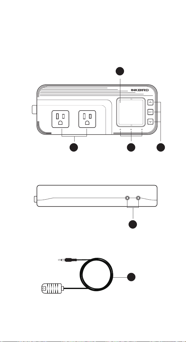
37
Functions on screen
PV:
In normal mode, the measured humidity is displayed. In
settings mode, it will display menu code.
SV:In normal mode, the humidity setting value is displayed.
In setting mode, it will display the setting value.
Output(WORK1/WORK2) Instruction
WORK1:
The humidif ication output
WORK2: The dehumidif ication output
Indicator LED:
●Red LED is on WORK1 output is on.
●Green LED is on WORK2 output is on.
●Green LED is blinking WORK2 output is performing the
function of compressor delay.
●Yellow LED is on The controller is in the setting mode.
Button Instruction
Please read the detail on 2.Button Operation Instructions
below
Probe interface
Humidity probe can be insert into P1 or P2 interface.
humidity probe
If the controller display Er, you may get a false humidity
probe, please try harder to insert the probe and rotate it to
make good contact. If the problem is still persists, it is likely
the internal probe wire has been damaged by the moisture or
heat temperature.
The probe and cable cannot be touched by the flame.
Do not exceed the probe humidity or temperature range to
avoid damaging
2 Button Operation Instructions
2.1 Restore Default Settings
Press " " button to power on, the buzzer will make a short
call, indicating that all parameters of the user's humidity probe
function return to the default setting value.
2.2 “ ” and “ ”Button Function in Normal Operation
Mode
Press " ", PV shows HD, SV shows humidif ication difference
value; press " ", PV shows DD, SV shows dehumidification
difference value, and it will be back to the normal display if
there is no operation for 3 seconds or pressing the "
SET"
button.
2.3 “SET” Button Function in normal operation mode
Short press the “
SET” button to enter the quick setting
humidity setting value mode. SV shows the humidity value
and flashes, and short press “ ” or “ ” button to increase or
decrease the setting value, long press “ ” or “ ”button to
quickly increase or decrease the setting value, and press the
"
SET" button again to confirm and exit. If there is no operation,
it will automatically exit after 10 seconds and save the setting
value.
2.4 Button Function in Setting Mode
When the controller is working normally, press the “SET”
button for 2 seconds to enter the setting mode, the PV screen
shows the first menu code “
HS” and the SV shows the
corresponding setting value. Press “
SET” button to scroll
down the menu item and save the parameters of the previous
menu item. Press “ ” or “ ”button to change the current
setting value. If in the setting state, there is no button
operation within 30 seconds or long press "
SET" button for 2
seconds, exit and save the setting state, return to normal
operation mode.
56.8
66.0
WORK1 WORK2
A
B C D
E
F
P1 P2
1 Get to Know the Controller
Output(WORK1/WORK2) Instruction
WORK1: The P1 heating/cooling output
WORK2: The P2 heating/cooling output
Indicator LED:
●Red LED is on WORK1 output is on.
●Red LED is blinking WORK1 output is performing the
function of compressor delay.
●Green LED is on WORK2 output is on.
●Green LED is blinking WORK2 output is performing the
function of compressor delay.
●Yellow LED is on The controller is in the setting mode.
Button Instruction
Please read the detail on 2.Button Operation Instructions below
Probe interface
Two temperature probes can be insert into P1 and P2 interface.
Temperature probe
●If the controller display Er, you may get a false temperature
probe, please try harder to insert the probe and rotate it to make
good contact. If the problem is still persists, it is likely the
internal probe wire has been damaged by the moisture or heat
temperature.
●The probe and cable cannot be touched by the flame.
●Do not exceed the probe temperature range to avoid
damaging.
2 Button Operation Instructions
2.1 Restore Default Settings
Press and hold the “ " button to power on, the buzzer will
make a short call, indicating that all parameters of the user's
temperature and humidity probe function return to the default
setting value.
2.2 “ ” and “ ”Button Function in Normal Operation
Mode
Press the “ ", PV shows the current temperature setting
value , SV shows current humidification value; press “ ", PV
shows current temperature value, SV the current humidification
setting value , and It will be back to the normal display if there is
no operation for 3 seconds orpressing the "
SET" button.
2.3 “SET” Button Function in Normal Operation Mode
Short press the “
SET” button to enter the quick setting
temperature and humidity value mode. PV shows the current
temperature setting value and flashes, and short press “ ” or
“ ” button to increase or decrease the setting value, long
press “ ” or “ ”button to quickly increase or decrease the
setting value, Short press the “
SET” button again,SV shows
the current humidity setting value and flashes, and short press
“ ” or “ ” button to increase or decrease the setting value,
long press “ ” or “ ”button to quickly increase or decrease
the setting value and lastly press the "
SET" button again to
confirm and exit. If there is no operation, it will automatically
exit after 10 seconds and save the setting value.
2.4 Button Function in Setting Mode
When the controller is working normally, press the “SET” button
for 2 seconds to enter the setting mode,the PV shows the first
menu code“
”, SV shows the corresponding setting value.
Press “
SET” button to scroll down the menu item and save the
parameters of the previous menu item. Press“ ” or
“ ”button to change the current setting value. Selected T to
enter the temperature parameter modification mode; selected H
to enter the humidity parameter modification mode. If in the
setting state, there is no operation within 30 seconds or long
press "
SET" button for 2 seconds, it will exit and save the
setting state and return to normal operation mode.

38
Functions on screen
PV:
In normal mode, the measured humidity is displayed. In
settings mode, it will display menu code.
SV:In normal mode, the humidity setting value is displayed.
In setting mode, it will display the setting value.
Output(WORK1/WORK2) Instruction
WORK1:
The humidif ication output
WORK2: The dehumidif ication output
Indicator LED:
●Red LED is on WORK1 output is on.
●Green LED is on WORK2 output is on.
●Green LED is blinking WORK2 output is performing the
function of compressor delay.
●Yellow LED is on The controller is in the setting mode.
Button Instruction
Please read the detail on 2.Button Operation Instructions
below
Probe interface
Humidity probe can be insert into P1 or P2 interface.
humidity probe
If the controller display Er, you may get a false humidity
probe, please try harder to insert the probe and rotate it to
make good contact. If the problem is still persists, it is likely
the internal probe wire has been damaged by the moisture or
heat temperature.
The probe and cable cannot be touched by the flame.
Do not exceed the probe humidity or temperature range to
avoid damaging
2 Button Operation Instructions
2.1 Restore Default Settings
Press " " button to power on, the buzzer will make a short
call, indicating that all parameters of the user's humidity probe
function return to the default setting value.
2.2 “ ” and “ ”Button Function in Normal Operation
Mode
Press " ", PV shows HD, SV shows humidif ication difference
value; press " ", PV shows DD, SV shows dehumidification
difference value, and it will be back to the normal display if
there is no operation for 3 seconds or pressing the "
SET"
button.
2.3 “SET” Button Function in normal operation mode
Short press the “
SET” button to enter the quick setting
humidity setting value mode. SV shows the humidity value
and flashes, and short press “ ” or “ ” button to increase or
decrease the setting value, long press “ ” or “ ”button to
quickly increase or decrease the setting value, and press the
"
SET" button again to confirm and exit. If there is no operation,
it will automatically exit after 10 seconds and save the setting
value.
2.4 Button Function in Setting Mode
When the controller is working normally, press the “SET”
button for 2 seconds to enter the setting mode, the PV screen
shows the first menu code “
HS” and the SV shows the
corresponding setting value. Press “
SET” button to scroll
down the menu item and save the parameters of the previous
menu item. Press “ ” or “ ”button to change the current
setting value. If in the setting state, there is no button
operation within 30 seconds or long press "
SET" button for 2
seconds, exit and save the setting state, return to normal
operation mode.
A
B
C
D
E
F

39
Functions on screen
PV:
In normal mode, the measured humidity is displayed. In
settings mode, it will display menu code.
SV:In normal mode, the humidity setting value is displayed.
In setting mode, it will display the setting value.
Output(WORK1/WORK2) Instruction
WORK1:
The humidif ication output
WORK2: The dehumidif ication output
Indicator LED:
●Red LED is on WORK1 output is on.
●Green LED is on WORK2 output is on.
●Green LED is blinking WORK2 output is performing the
function of compressor delay.
●Yellow LED is on The controller is in the setting mode.
Button Instruction
Please read the detail on 2.Button Operation Instructions
below
Probe interface
Humidity probe can be insert into P1 or P2 interface.
humidity probe
If the controller display Er, you may get a false humidity
probe, please try harder to insert the probe and rotate it to
make good contact. If the problem is still persists, it is likely
the internal probe wire has been damaged by the moisture or
heat temperature.
The probe and cable cannot be touched by the flame.
Do not exceed the probe humidity or temperature range to
avoid damaging
2 Button Operation Instructions
2.1 Restore Default Settings
Press " " button to power on, the buzzer will make a short
call, indicating that all parameters of the user's humidity probe
function return to the default setting value.
2.2 “ ” and “ ”Button Function in Normal Operation
Mode
Press " ", PV shows HD, SV shows humidif ication difference
value; press " ", PV shows DD, SV shows dehumidification
difference value, and it will be back to the normal display if
there is no operation for 3 seconds or pressing the "
SET"
button.
2.3 “SET” Button Function in normal operation mode
Short press the “
SET” button to enter the quick setting
humidity setting value mode. SV shows the humidity value
and flashes, and short press “ ” or “ ” button to increase or
decrease the setting value, long press “ ” or “ ”button to
quickly increase or decrease the setting value, and press the
"
SET" button again to confirm and exit. If there is no operation,
it will automatically exit after 10 seconds and save the setting
value.
2.4 Button Function in Setting Mode
When the controller is working normally, press the “SET”
button for 2 seconds to enter the setting mode, the PV screen
shows the first menu code “
HS” and the SV shows the
corresponding setting value. Press “
SET” button to scroll
down the menu item and save the parameters of the previous
menu item. Press “ ” or “ ”button to change the current
setting value. If in the setting state, there is no button
operation within 30 seconds or long press "
SET" button for 2
seconds, exit and save the setting state, return to normal
operation mode.
Output(WORK1/WORK2) Instruction
WORK1: The P1 heating/cooling output
WORK2: The P2 heating/cooling output
Indicator LED:
●Red LED is on WORK1 output is on.
●Red LED is blinking WORK1 output is performing the
function of compressor delay.
●Green LED is on WORK2 output is on.
●Green LED is blinking WORK2 output is performing the
function of compressor delay.
●Yellow LED is on The controller is in the setting mode.
Button Instruction
Please read the detail on 2.Button Operation Instructions below
Probe interface
Two temperature probes can be insert into P1 and P2 interface.
Temperature probe
●If the controller display Er, you may get a false temperature
probe, please try harder to insert the probe and rotate it to make
good contact. If the problem is still persists, it is likely the
internal probe wire has been damaged by the moisture or heat
temperature.
●The probe and cable cannot be touched by the flame.
●Do not exceed the probe temperature range to avoid
damaging.
2 Button Operation Instructions
2.1 Restore Default Settings
Press and hold the “ " button to power on, the buzzer will
make a short call, indicating that all parameters of the user's
temperature and humidity probe function return to the default
setting value.
2.2 “ ” and “ ”Button Function in Normal Operation
Mode
Press the “ ", PV shows the current temperature setting
value , SV shows current humidification value; press “ ", PV
shows current temperature value, SV the current humidification
setting value , and It will be back to the normal display if there is
no operation for 3 seconds orpressing the "
SET" button.
2.3 “SET” Button Function in Normal Operation Mode
Short press the “
SET” button to enter the quick setting
temperature and humidity value mode. PV shows the current
temperature setting value and flashes, and short press “ ” or
“ ” button to increase or decrease the setting value, long
press “ ” or “ ”button to quickly increase or decrease the
setting value, Short press the “
SET” button again,SV shows
the current humidity setting value and flashes, and short press
“ ” or “ ” button to increase or decrease the setting value,
long press “ ” or “ ”button to quickly increase or decrease
the setting value and lastly press the "
SET" button again to
confirm and exit. If there is no operation, it will automatically
exit after 10 seconds and save the setting value.
2.4 Button Function in Setting Mode
When the controller is working normally, press the “SET” button
for 2 seconds to enter the setting mode,the PV shows the first
menu code“
”, SV shows the corresponding setting value.
Press “
SET” button to scroll down the menu item and save the
parameters of the previous menu item. Press“ ” or
“ ”button to change the current setting value. Selected T to
enter the temperature parameter modification mode; selected H
to enter the humidity parameter modification mode. If in the
setting state, there is no operation within 30 seconds or long
press "
SET" button for 2 seconds, it will exit and save the
setting state and return to normal operation mode.
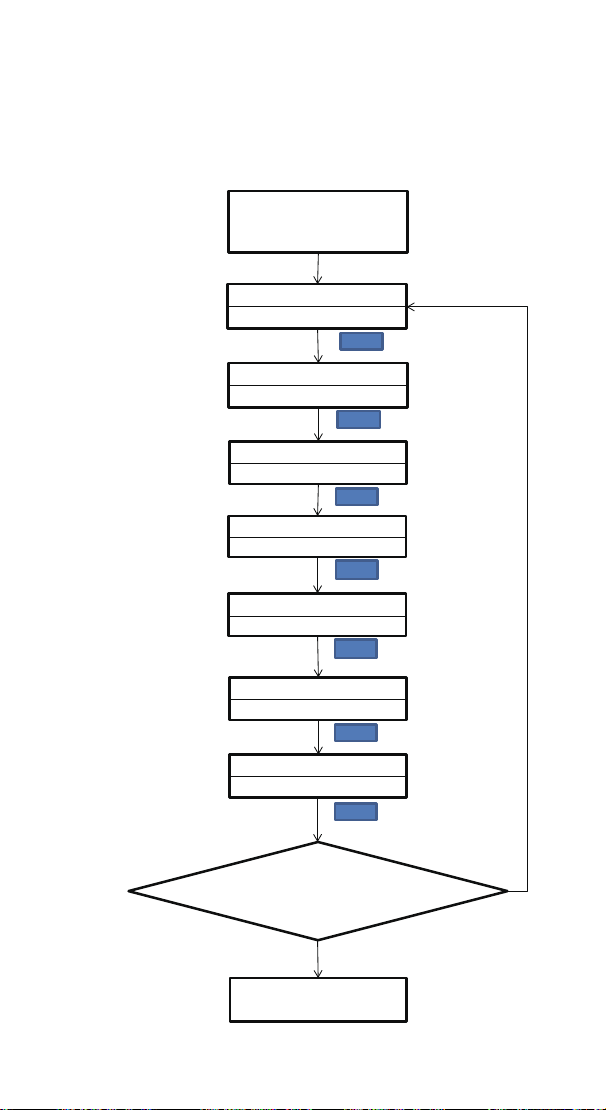
40
Functions on screen
PV:
In normal mode, the measured humidity is displayed. In
settings mode, it will display menu code.
SV:In normal mode, the humidity setting value is displayed.
In setting mode, it will display the setting value.
Output(WORK1/WORK2) Instruction
WORK1:
The humidif ication output
WORK2: The dehumidif ication output
Indicator LED:
●Red LED is on WORK1 output is on.
●Green LED is on WORK2 output is on.
●Green LED is blinking WORK2 output is performing the
function of compressor delay.
●Yellow LED is on The controller is in the setting mode.
Button Instruction
Please read the detail on 2.Button Operation Instructions
below
Probe interface
Humidity probe can be insert into P1 or P2 interface.
humidity probe
If the controller display Er, you may get a false humidity
probe, please try harder to insert the probe and rotate it to
make good contact. If the problem is still persists, it is likely
the internal probe wire has been damaged by the moisture or
heat temperature.
The probe and cable cannot be touched by the flame.
Do not exceed the probe humidity or temperature range to
avoid damaging
2 Button Operation Instructions
2.1 Restore Default Settings
Press " " button to power on, the buzzer will make a short
call, indicating that all parameters of the user's humidity probe
function return to the default setting value.
2.2 “ ” and “ ”Button Function in Normal Operation
Mode
Press " ", PV shows HD, SV shows humidif ication difference
value; press " ", PV shows DD, SV shows dehumidification
difference value, and it will be back to the normal display if
there is no operation for 3 seconds or pressing the "
SET"
button.
2.3 “SET” Button Function in normal operation mode
Short press the “
SET” button to enter the quick setting
humidity setting value mode. SV shows the humidity value
and flashes, and short press “ ” or “ ” button to increase or
decrease the setting value, long press “ ” or “ ”button to
quickly increase or decrease the setting value, and press the
"
SET" button again to confirm and exit. If there is no operation,
it will automatically exit after 10 seconds and save the setting
value.
2.4 Button Function in Setting Mode
When the controller is working normally, press the “SET”
button for 2 seconds to enter the setting mode, the PV screen
shows the first menu code “
HS” and the SV shows the
corresponding setting value. Press “
SET” button to scroll
down the menu item and save the parameters of the previous
menu item. Press “ ” or “ ”button to change the current
setting value. If in the setting state, there is no button
operation within 30 seconds or long press "
SET" button for 2
seconds, exit and save the setting state, return to normal
operation mode.
3. Menu Instruction
3.1 Setting mode Flow Chart
Output(WORK1/WORK2) Instruction
WORK1: The P1 heating/cooling output
WORK2: The P2 heating/cooling output
Indicator LED:
●Red LED is on WORK1 output is on.
●Red LED is blinking WORK1 output is performing the
function of compressor delay.
●Green LED is on WORK2 output is on.
●Green LED is blinking WORK2 output is performing the
function of compressor delay.
●Yellow LED is on The controller is in the setting mode.
Button Instruction
Please read the detail on 2.Button Operation Instructions below
Probe interface
Two temperature probes can be insert into P1 and P2 interface.
Temperature probe
●If the controller display Er, you may get a false temperature
probe, please try harder to insert the probe and rotate it to make
good contact. If the problem is still persists, it is likely the
internal probe wire has been damaged by the moisture or heat
temperature.
●The probe and cable cannot be touched by the flame.
●Do not exceed the probe temperature range to avoid
damaging.
2 Button Operation Instructions
2.1 Restore Default Settings
Press and hold the “ " button to power on, the buzzer will
make a short call, indicating that all parameters of the user's
temperature and humidity probe function return to the default
setting value.
2.2 “ ” and “ ”Button Function in Normal Operation
Mode
Press the “ ", PV shows the current temperature setting
value , SV shows current humidification value; press “ ", PV
shows current temperature value, SV the current humidification
setting value , and It will be back to the normal display if there is
no operation for 3 seconds orpressing the "
SET" button.
2.3 “SET” Button Function in Normal Operation Mode
Short press the “
SET” button to enter the quick setting
temperature and humidity value mode. PV shows the current
temperature setting value and flashes, and short press “ ” or
“ ” button to increase or decrease the setting value, long
press “ ” or “ ”button to quickly increase or decrease the
setting value, Short press the “
SET” button again,SV shows
the current humidity setting value and flashes, and short press
“ ” or “ ” button to increase or decrease the setting value,
long press “ ” or “ ”button to quickly increase or decrease
the setting value and lastly press the "
SET" button again to
confirm and exit. If there is no operation, it will automatically
exit after 10 seconds and save the setting value.
2.4 Button Function in Setting Mode
When the controller is working normally, press the “SET” button
for 2 seconds to enter the setting mode,the PV shows the first
menu code“
”, SV shows the corresponding setting value.
Press “
SET” button to scroll down the menu item and save the
parameters of the previous menu item. Press“ ” or
“ ”button to change the current setting value. Selected T to
enter the temperature parameter modification mode; selected H
to enter the humidity parameter modification mode. If in the
setting state, there is no operation within 30 seconds or long
press "
SET" button for 2 seconds, it will exit and save the
setting state and return to normal operation mode.
Humidity Set Value
Humidification difference value
Dehumidification difference value
Alarm High humidity Limit
SET
Alarm Low humidity Limit
Compressor Delay Time
Humidity Calibration
Press "SET" Key for over 2
seconds to enter parameters
setting mode
HD
5.0%RH
DD
5.0%RH
AH
99.0%RH
AL
5.0%RH
PT
0Minute
CA
0.0%RH
SET
SET
SET
SET
SET
SET
SET
HS
50.0%RH
No Key for 30 seconds or Presss
"SET" key for over 2 second ?
Working normally

41
Code Symbol Function Setting Range
Default
Setting
HS HS
Humidity Setting
Value
5.0%RH ~99.0%RH 50.0%RH
HD
Humidification
Difference Value
1.0%RH ~20.0%RH 5.0%RH
DD
Dehumidification
Difference Value
1.0%RH ~20.0%RH 5.0%RH
AH AH
Alarm High Humidity
Limit
5.0%RH ~99.0%RH 99.0%RH
AL
Alarm Low Humidity
Limit
5.0%RH ~99.0%RH 5.0%RH
PT
Compressor Delay
Time
0~10 minutes 0 minute
CA CA Humidity Calibration -20.0%RH ~20.0%RH 0.0%RH
3.2 Setting Menu Instruction
4.Control Function Instruction
4.1 Setting Humidity Control Function ( HS ,HD, DD )
When the controller works normally, PV shows the measured
humidity, meantime SV shows the humidity setting value, and
automatically recognizes and converts for the humidification
and dehumidification working mode .WORK1 is the humidifica-
tion output, furthermore the red led is the WORK1 humidifica-
tion output status indicator; WORK2 is dehumidification
output, furthermore the green led is WORK2 dehumidification
output status indicator.
When PV(measured humidity) ≤ HS(humidity setting value) –
HD(humidification difference value), the controller will enter
into the humidification state, the red led is on, WORK1 output
works. When PV(measured humidity) ≥ HS(humidity setting
value), the red led is off and the WORK1 output turns off.
When PV(measured humidity) ≥ HS(humidity setting value) +
DD(dehumidification difference value), the controller will enter
into the dehumidification state, the green led is on, WORK2
output works; green led flashes, indicating that the dehumidi-
fication device is in delay protection state. When PV(measured
humidity) ≤HS( humidity setting value), the green led is off and
the WORK2 output turns off.
For example, when setting HS=50.0%RH,DD=5.0%RH,
HD=8.0%RH, measured humidity value ≥55.0%RH(HS+DD),the
controller will enter the dehumidification state, when
measured humidity value ≤50.0%RH, dehumidification will
Functions on screen
PV:
In normal mode, the measured humidity is displayed. In
settings mode, it will display menu code.
SV:In normal mode, the humidity setting value is displayed.
In setting mode, it will display the setting value.
Output(WORK1/WORK2) Instruction
WORK1:
The humidif ication output
WORK2: The dehumidif ication output
Indicator LED:
●Red LED is on WORK1 output is on.
●Green LED is on WORK2 output is on.
●Green LED is blinking WORK2 output is performing the
function of compressor delay.
●Yellow LED is on The controller is in the setting mode.
Button Instruction
Please read the detail on 2.Button Operation Instructions
below
Probe interface
Humidity probe can be insert into P1 or P2 interface.
humidity probe
If the controller display Er, you may get a false humidity
probe, please try harder to insert the probe and rotate it to
make good contact. If the problem is still persists, it is likely
the internal probe wire has been damaged by the moisture or
heat temperature.
The probe and cable cannot be touched by the flame.
Do not exceed the probe humidity or temperature range to
avoid damaging
2 Button Operation Instructions
2.1 Restore Default Settings
Press " " button to power on, the buzzer will make a short
call, indicating that all parameters of the user's humidity probe
function return to the default setting value.
2.2 “ ” and “ ”Button Function in Normal Operation
Mode
Press " ", PV shows HD, SV shows humidif ication difference
value; press " ", PV shows DD, SV shows dehumidification
difference value, and it will be back to the normal display if
there is no operation for 3 seconds or pressing the "
SET"
button.
2.3 “SET” Button Function in normal operation mode
Short press the “
SET” button to enter the quick setting
humidity setting value mode. SV shows the humidity value
and flashes, and short press “ ” or “ ” button to increase or
decrease the setting value, long press “ ” or “ ”button to
quickly increase or decrease the setting value, and press the
"
SET" button again to confirm and exit. If there is no operation,
it will automatically exit after 10 seconds and save the setting
value.
2.4 Button Function in Setting Mode
When the controller is working normally, press the “SET”
button for 2 seconds to enter the setting mode, the PV screen
shows the first menu code “
HS” and the SV shows the
corresponding setting value. Press “
SET” button to scroll
down the menu item and save the parameters of the previous
menu item. Press “ ” or “ ”button to change the current
setting value. If in the setting state, there is no button
operation within 30 seconds or long press "
SET" button for 2
seconds, exit and save the setting state, return to normal
operation mode.
Output(WORK1/WORK2) Instruction
WORK1: The P1 heating/cooling output
WORK2: The P2 heating/cooling output
Indicator LED:
●Red LED is on WORK1 output is on.
●Red LED is blinking WORK1 output is performing the
function of compressor delay.
●Green LED is on WORK2 output is on.
●Green LED is blinking WORK2 output is performing the
function of compressor delay.
●Yellow LED is on The controller is in the setting mode.
Button Instruction
Please read the detail on 2.Button Operation Instructions below
Probe interface
Two temperature probes can be insert into P1 and P2 interface.
Temperature probe
●If the controller display Er, you may get a false temperature
probe, please try harder to insert the probe and rotate it to make
good contact. If the problem is still persists, it is likely the
internal probe wire has been damaged by the moisture or heat
temperature.
●The probe and cable cannot be touched by the flame.
●Do not exceed the probe temperature range to avoid
damaging.
2 Button Operation Instructions
2.1 Restore Default Settings
Press and hold the “ " button to power on, the buzzer will
make a short call, indicating that all parameters of the user's
temperature and humidity probe function return to the default
setting value.
2.2 “ ” and “ ”Button Function in Normal Operation
Mode
Press the “ ", PV shows the current temperature setting
value , SV shows current humidification value; press “ ", PV
shows current temperature value, SV the current humidification
setting value , and It will be back to the normal display if there is
no operation for 3 seconds orpressing the "
SET" button.
2.3 “SET” Button Function in Normal Operation Mode
Short press the “
SET” button to enter the quick setting
temperature and humidity value mode. PV shows the current
temperature setting value and flashes, and short press “ ” or
“ ” button to increase or decrease the setting value, long
press “ ” or “ ”button to quickly increase or decrease the
setting value, Short press the “
SET” button again,SV shows
the current humidity setting value and flashes, and short press
“ ” or “ ” button to increase or decrease the setting value,
long press “ ” or “ ”button to quickly increase or decrease
the setting value and lastly press the "
SET" button again to
confirm and exit. If there is no operation, it will automatically
exit after 10 seconds and save the setting value.
2.4 Button Function in Setting Mode
When the controller is working normally, press the “SET” button
for 2 seconds to enter the setting mode,the PV shows the first
menu code“
”, SV shows the corresponding setting value.
Press “
SET” button to scroll down the menu item and save the
parameters of the previous menu item. Press“ ” or
“ ”button to change the current setting value. Selected T to
enter the temperature parameter modification mode; selected H
to enter the humidity parameter modification mode. If in the
setting state, there is no operation within 30 seconds or long
press "
SET" button for 2 seconds, it will exit and save the
setting state and return to normal operation mode.

42
stop; When the measured humidity value is ≤ 42%RH (HS-HD),
the controller will enter the humidification state , and when the
measured humidity value is ≥ 50%RH, the humidification will
stop.
4.2 Alarm High / Low Humidity Limit Settings (AH,AL)
When measured humidity ≥ AH(alarm high humidity limit), PV
shows alternate AH with measured humidity, buzzer will
“bi-bi-Biii” alarm, until the humidity <AH, buzzer off and return
to normal display and control. Or press the button to turn the
buzzer alarm off only.
When measured humidity ≤ AL( alarm low humidity limit),PV
shows alternate AL with measured humidity, buzzer will
“bi-bi-Biii” alarm, until the humidity <AL, buzzer off and return
to normal display and control. Or press the button to turn the
buzzer alarm off only.
4.3 Dehumidifying Delay Protection Time(PT)
In the dehumidifying mode, when the power is turned on for
the first time, it will not start dehumidification immediately
when PV(measured humidity value) ≥ HS(humidity setting
value)+ DD(dehumidification difference setting value),but
waiting for a delay time(PT).
When two adjacent of dehumidification starting intervals are
greater than the delay time, it will immediately start
dehumidification ; When two adjacent of dehumidification
starting intervals are less than the delay time, it needs to
operate the remaining delay time to start the dehumidification
Delay time will start counting from the dehumidification
output off.
4.4 Humidity Calibration(CA)
When the measured humidity deviates from the standard
humidity, the humidity calibration function can be used to
make the measured value of the instrument consistent with
the standard value. The calibrated humidity = the measured
humidity value + the calibration value.
Functions on screen
PV:
In normal mode, the measured humidity is displayed. In
settings mode, it will display menu code.
SV:In normal mode, the humidity setting value is displayed.
In setting mode, it will display the setting value.
Output(WORK1/WORK2) Instruction
WORK1:
The humidif ication output
WORK2: The dehumidif ication output
Indicator LED:
●Red LED is on WORK1 output is on.
●Green LED is on WORK2 output is on.
●Green LED is blinking WORK2 output is performing the
function of compressor delay.
●Yellow LED is on The controller is in the setting mode.
Button Instruction
Please read the detail on 2.Button Operation Instructions
below
Probe interface
Humidity probe can be insert into P1 or P2 interface.
humidity probe
If the controller display Er, you may get a false humidity
probe, please try harder to insert the probe and rotate it to
make good contact. If the problem is still persists, it is likely
the internal probe wire has been damaged by the moisture or
heat temperature.
The probe and cable cannot be touched by the flame.
Do not exceed the probe humidity or temperature range to
avoid damaging
2 Button Operation Instructions
2.1 Restore Default Settings
Press " " button to power on, the buzzer will make a short
call, indicating that all parameters of the user's humidity probe
function return to the default setting value.
2.2 “ ” and “ ”Button Function in Normal Operation
Mode
Press " ", PV shows HD, SV shows humidif ication difference
value; press " ", PV shows DD, SV shows dehumidification
difference value, and it will be back to the normal display if
there is no operation for 3 seconds or pressing the "
SET"
button.
2.3 “SET” Button Function in normal operation mode
Short press the “
SET” button to enter the quick setting
humidity setting value mode. SV shows the humidity value
and flashes, and short press “ ” or “ ” button to increase or
decrease the setting value, long press “ ” or “ ”button to
quickly increase or decrease the setting value, and press the
"
SET" button again to confirm and exit. If there is no operation,
it will automatically exit after 10 seconds and save the setting
value.
2.4 Button Function in Setting Mode
When the controller is working normally, press the “SET”
button for 2 seconds to enter the setting mode, the PV screen
shows the first menu code “
HS” and the SV shows the
corresponding setting value. Press “
SET” button to scroll
down the menu item and save the parameters of the previous
menu item. Press “ ” or “ ”button to change the current
setting value. If in the setting state, there is no button
operation within 30 seconds or long press "
SET" button for 2
seconds, exit and save the setting state, return to normal
operation mode.
Output(WORK1/WORK2) Instruction
WORK1: The P1 heating/cooling output
WORK2: The P2 heating/cooling output
Indicator LED:
●Red LED is on WORK1 output is on.
●Red LED is blinking WORK1 output is performing the
function of compressor delay.
●Green LED is on WORK2 output is on.
●Green LED is blinking WORK2 output is performing the
function of compressor delay.
●Yellow LED is on The controller is in the setting mode.
Button Instruction
Please read the detail on 2.Button Operation Instructions below
Probe interface
Two temperature probes can be insert into P1 and P2 interface.
Temperature probe
●If the controller display Er, you may get a false temperature
probe, please try harder to insert the probe and rotate it to make
good contact. If the problem is still persists, it is likely the
internal probe wire has been damaged by the moisture or heat
temperature.
●The probe and cable cannot be touched by the flame.
●Do not exceed the probe temperature range to avoid
damaging.
2 Button Operation Instructions
2.1 Restore Default Settings
Press and hold the “ " button to power on, the buzzer will
make a short call, indicating that all parameters of the user's
temperature and humidity probe function return to the default
setting value.
2.2 “ ” and “ ”Button Function in Normal Operation
Mode
Press the “ ", PV shows the current temperature setting
value , SV shows current humidification value; press “ ", PV
shows current temperature value, SV the current humidification
setting value , and It will be back to the normal display if there is
no operation for 3 seconds orpressing the "
SET" button.
2.3 “SET” Button Function in Normal Operation Mode
Short press the “
SET” button to enter the quick setting
temperature and humidity value mode. PV shows the current
temperature setting value and flashes, and short press “ ” or
“ ” button to increase or decrease the setting value, long
press “ ” or “ ”button to quickly increase or decrease the
setting value, Short press the “
SET” button again,SV shows
the current humidity setting value and flashes, and short press
“ ” or “ ” button to increase or decrease the setting value,
long press “ ” or “ ”button to quickly increase or decrease
the setting value and lastly press the "
SET" button again to
confirm and exit. If there is no operation, it will automatically
exit after 10 seconds and save the setting value.
2.4 Button Function in Setting Mode
When the controller is working normally, press the “SET” button
for 2 seconds to enter the setting mode,the PV shows the first
menu code“
”, SV shows the corresponding setting value.
Press “
SET” button to scroll down the menu item and save the
parameters of the previous menu item. Press“ ” or
“ ”button to change the current setting value. Selected T to
enter the temperature parameter modification mode; selected H
to enter the humidity parameter modification mode. If in the
setting state, there is no operation within 30 seconds or long
press "
SET" button for 2 seconds, it will exit and save the
setting state and return to normal operation mode.
TEMPERATURE&
HUMIDITY
Controller Manual
Equivalent to IHC-230
Temperature & Humidity
Controller Manual
ITC-608T
43
Part 6
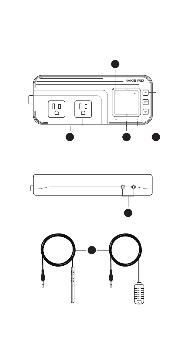
Functions on screen
PV:
In normal mode, the measured humidity is displayed. In
settings mode, it will display menu code.
SV:In normal mode, the humidity setting value is displayed.
In setting mode, it will display the setting value.
Output(WORK1/WORK2) Instruction
WORK1:
The humidif ication output
WORK2: The dehumidif ication output
Indicator LED:
●Red LED is on WORK1 output is on.
●Green LED is on WORK2 output is on.
●Green LED is blinking WORK2 output is performing the
function of compressor delay.
●Yellow LED is on The controller is in the setting mode.
Button Instruction
Please read the detail on 2.Button Operation Instructions
below
Probe interface
Humidity probe can be insert into P1 or P2 interface.
humidity probe
If the controller display Er, you may get a false humidity
probe, please try harder to insert the probe and rotate it to
make good contact. If the problem is still persists, it is likely
the internal probe wire has been damaged by the moisture or
heat temperature.
The probe and cable cannot be touched by the flame.
Do not exceed the probe humidity or temperature range to
avoid damaging
2 Button Operation Instructions
2.1 Restore Default Settings
Press " " button to power on, the buzzer will make a short
call, indicating that all parameters of the user's humidity probe
function return to the default setting value.
2.2 “ ” and “ ”Button Function in Normal Operation
Mode
Press " ", PV shows HD, SV shows humidif ication difference
value; press " ", PV shows DD, SV shows dehumidification
difference value, and it will be back to the normal display if
there is no operation for 3 seconds or pressing the "
SET"
button.
2.3 “SET” Button Function in normal operation mode
Short press the “
SET” button to enter the quick setting
humidity setting value mode. SV shows the humidity value
and flashes, and short press “ ” or “ ” button to increase or
decrease the setting value, long press “ ” or “ ”button to
quickly increase or decrease the setting value, and press the
"
SET" button again to confirm and exit. If there is no operation,
it will automatically exit after 10 seconds and save the setting
value.
2.4 Button Function in Setting Mode
When the controller is working normally, press the “SET”
button for 2 seconds to enter the setting mode, the PV screen
shows the first menu code “
HS” and the SV shows the
corresponding setting value. Press “
SET” button to scroll
down the menu item and save the parameters of the previous
menu item. Press “ ” or “ ”button to change the current
setting value. If in the setting state, there is no button
operation within 30 seconds or long press "
SET" button for 2
seconds, exit and save the setting state, return to normal
operation mode.
Output(WORK1/WORK2) Instruction
WORK1: The P1 heating/cooling output
WORK2: The P2 heating/cooling output
Indicator LED:
●Red LED is on WORK1 output is on.
●Red LED is blinking WORK1 output is performing the
function of compressor delay.
●Green LED is on WORK2 output is on.
●Green LED is blinking WORK2 output is performing the
function of compressor delay.
●Yellow LED is on The controller is in the setting mode.
Button Instruction
Please read the detail on 2.Button Operation Instructions below
Probe interface
Two temperature probes can be insert into P1 and P2 interface.
Temperature probe
●If the controller display Er, you may get a false temperature
probe, please try harder to insert the probe and rotate it to make
good contact. If the problem is still persists, it is likely the
internal probe wire has been damaged by the moisture or heat
temperature.
●The probe and cable cannot be touched by the flame.
●Do not exceed the probe temperature range to avoid
damaging.
2 Button Operation Instructions
2.1 Restore Default Settings
Press and hold the “ " button to power on, the buzzer will
make a short call, indicating that all parameters of the user's
temperature and humidity probe function return to the default
setting value.
2.2 “ ” and “ ”Button Function in Normal Operation
Mode
Press the “ ", PV shows the current temperature setting
value , SV shows current humidification value; press “ ", PV
shows current temperature value, SV the current humidification
setting value , and It will be back to the normal display if there is
no operation for 3 seconds orpressing the "
SET" button.
2.3 “SET” Button Function in Normal Operation Mode
Short press the “
SET” button to enter the quick setting
temperature and humidity value mode. PV shows the current
temperature setting value and flashes, and short press “ ” or
“ ” button to increase or decrease the setting value, long
press “ ” or “ ”button to quickly increase or decrease the
setting value, Short press the “
SET” button again,SV shows
the current humidity setting value and flashes, and short press
“ ” or “ ” button to increase or decrease the setting value,
long press “ ” or “ ”button to quickly increase or decrease
the setting value and lastly press the "
SET" button again to
confirm and exit. If there is no operation, it will automatically
exit after 10 seconds and save the setting value.
2.4 Button Function in Setting Mode
When the controller is working normally, press the “SET” button
for 2 seconds to enter the setting mode,the PV shows the first
menu code“
”, SV shows the corresponding setting value.
Press “
SET” button to scroll down the menu item and save the
parameters of the previous menu item. Press“ ” or
“ ”button to change the current setting value. Selected T to
enter the temperature parameter modification mode; selected H
to enter the humidity parameter modification mode. If in the
setting state, there is no operation within 30 seconds or long
press "
SET" button for 2 seconds, it will exit and save the
setting state and return to normal operation mode.
44
WORK1 WORK2
A
B C D
E
F
P1 P2
1 Get to Know the Controller
88.6
f
56.8
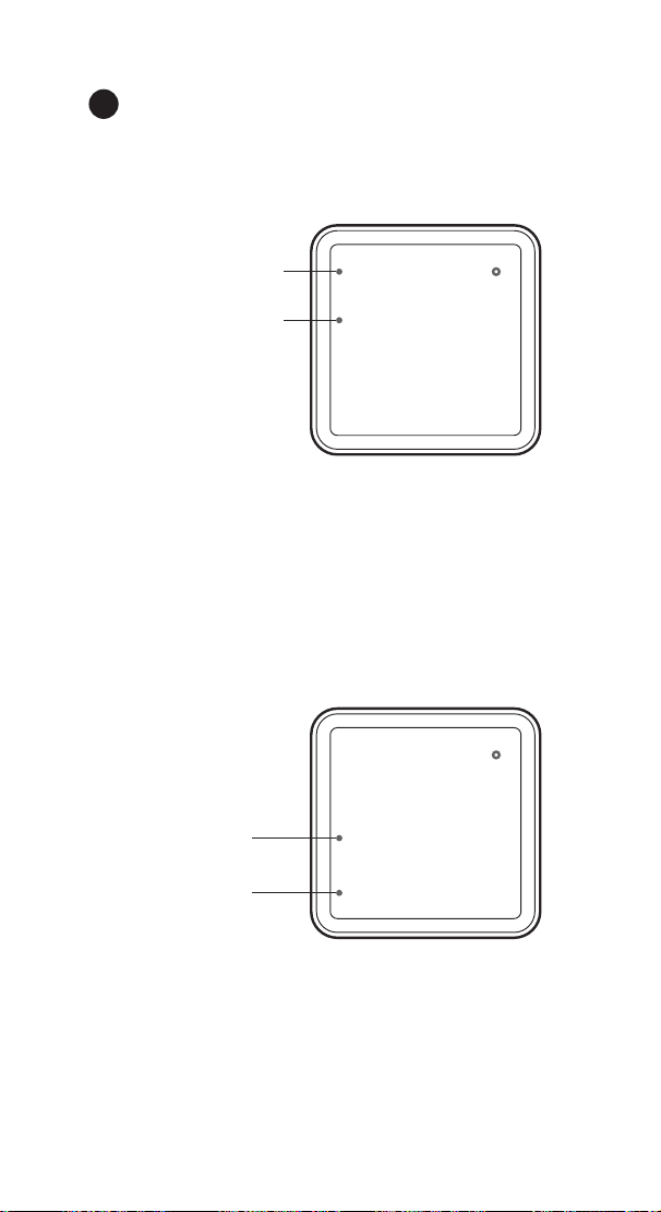
Functions on screen
PV:
In normal mode, the measured humidity is displayed. In
settings mode, it will display menu code.
SV:In normal mode, the humidity setting value is displayed.
In setting mode, it will display the setting value.
Output(WORK1/WORK2) Instruction
WORK1:
The humidif ication output
WORK2: The dehumidif ication output
Indicator LED:
●Red LED is on WORK1 output is on.
●Green LED is on WORK2 output is on.
●Green LED is blinking WORK2 output is performing the
function of compressor delay.
●Yellow LED is on The controller is in the setting mode.
Button Instruction
Please read the detail on 2.Button Operation Instructions
below
Probe interface
Humidity probe can be insert into P1 or P2 interface.
humidity probe
If the controller display Er, you may get a false humidity
probe, please try harder to insert the probe and rotate it to
make good contact. If the problem is still persists, it is likely
the internal probe wire has been damaged by the moisture or
heat temperature.
The probe and cable cannot be touched by the flame.
Do not exceed the probe humidity or temperature range to
avoid damaging
2 Button Operation Instructions
2.1 Restore Default Settings
Press " " button to power on, the buzzer will make a short
call, indicating that all parameters of the user's humidity probe
function return to the default setting value.
2.2 “ ” and “ ”Button Function in Normal Operation
Mode
Press " ", PV shows HD, SV shows humidif ication difference
value; press " ", PV shows DD, SV shows dehumidification
difference value, and it will be back to the normal display if
there is no operation for 3 seconds or pressing the "
SET"
button.
2.3 “SET” Button Function in normal operation mode
Short press the “
SET” button to enter the quick setting
humidity setting value mode. SV shows the humidity value
and flashes, and short press “ ” or “ ” button to increase or
decrease the setting value, long press “ ” or “ ”button to
quickly increase or decrease the setting value, and press the
"
SET" button again to confirm and exit. If there is no operation,
it will automatically exit after 10 seconds and save the setting
value.
2.4 Button Function in Setting Mode
When the controller is working normally, press the “SET”
button for 2 seconds to enter the setting mode, the PV screen
shows the first menu code “
HS” and the SV shows the
corresponding setting value. Press “
SET” button to scroll
down the menu item and save the parameters of the previous
menu item. Press “ ” or “ ”button to change the current
setting value. If in the setting state, there is no button
operation within 30 seconds or long press "
SET" button for 2
seconds, exit and save the setting state, return to normal
operation mode.
Output(WORK1/WORK2) Instruction
WORK1: The P1 heating/cooling output
WORK2: The P2 heating/cooling output
Indicator LED:
●Red LED is on WORK1 output is on.
●Red LED is blinking WORK1 output is performing the
function of compressor delay.
●Green LED is on WORK2 output is on.
●Green LED is blinking WORK2 output is performing the
function of compressor delay.
●Yellow LED is on The controller is in the setting mode.
Button Instruction
Please read the detail on 2.Button Operation Instructions below
Probe interface
Two temperature probes can be insert into P1 and P2 interface.
Temperature probe
●If the controller display Er, you may get a false temperature
probe, please try harder to insert the probe and rotate it to make
good contact. If the problem is still persists, it is likely the
internal probe wire has been damaged by the moisture or heat
temperature.
●The probe and cable cannot be touched by the flame.
●Do not exceed the probe temperature range to avoid
damaging.
2 Button Operation Instructions
2.1 Restore Default Settings
Press and hold the “ " button to power on, the buzzer will
make a short call, indicating that all parameters of the user's
temperature and humidity probe function return to the default
setting value.
2.2 “ ” and “ ”Button Function in Normal Operation
Mode
Press the “ ", PV shows the current temperature setting
value , SV shows current humidification value; press “ ", PV
shows current temperature value, SV the current humidification
setting value , and It will be back to the normal display if there is
no operation for 3 seconds orpressing the "
SET" button.
2.3 “SET” Button Function in Normal Operation Mode
Short press the “
SET” button to enter the quick setting
temperature and humidity value mode. PV shows the current
temperature setting value and flashes, and short press “ ” or
“ ” button to increase or decrease the setting value, long
press “ ” or “ ”button to quickly increase or decrease the
setting value, Short press the “
SET” button again,SV shows
the current humidity setting value and flashes, and short press
“ ” or “ ” button to increase or decrease the setting value,
long press “ ” or “ ”button to quickly increase or decrease
the setting value and lastly press the "
SET" button again to
confirm and exit. If there is no operation, it will automatically
exit after 10 seconds and save the setting value.
2.4 Button Function in Setting Mode
When the controller is working normally, press the “SET” button
for 2 seconds to enter the setting mode,the PV shows the first
menu code“
”, SV shows the corresponding setting value.
Press “
SET” button to scroll down the menu item and save the
parameters of the previous menu item. Press“ ” or
“ ”button to change the current setting value. Selected T to
enter the temperature parameter modification mode; selected H
to enter the humidity parameter modification mode. If in the
setting state, there is no operation within 30 seconds or long
press "
SET" button for 2 seconds, it will exit and save the
setting state and return to normal operation mode.
45
Functions on screen
PV:In normal mode, the measured temperature is displayed.
In settings mode, it will display menu code.
Heating indicator LED: If Temperature Control Function
selected heating mode, the indicator LED is on, otherwise off.
Cooling indicator LED: If Temperature Control Function
selected cooling mode, the indicator LED is on, otherwise off.
SV:In normal mode, the measured humidity is displayed. In
setting mode, it will display the setting value.
Humidification indicator LED: If humidity Control Function
selected humidification mode, the indicator LED is on,
otherwise off.
Dehumidification indicator LED: If humidity Control
Function selected dehumidification mode, the indicator LED is
on, otherwise off.
86.8
f
Heating indicator LED
Cooling indicator LED
88.6
f
Humidification
indicator LED
Dehumidification
indicator LED
A
56.8
56.8

Functions on screen
PV:
In normal mode, the measured humidity is displayed. In
settings mode, it will display menu code.
SV:In normal mode, the humidity setting value is displayed.
In setting mode, it will display the setting value.
Output(WORK1/WORK2) Instruction
WORK1:
The humidif ication output
WORK2: The dehumidif ication output
Indicator LED:
●Red LED is on WORK1 output is on.
●Green LED is on WORK2 output is on.
●Green LED is blinking WORK2 output is performing the
function of compressor delay.
●Yellow LED is on The controller is in the setting mode.
Button Instruction
Please read the detail on 2.Button Operation Instructions
below
Probe interface
Humidity probe can be insert into P1 or P2 interface.
humidity probe
If the controller display Er, you may get a false humidity
probe, please try harder to insert the probe and rotate it to
make good contact. If the problem is still persists, it is likely
the internal probe wire has been damaged by the moisture or
heat temperature.
The probe and cable cannot be touched by the flame.
Do not exceed the probe humidity or temperature range to
avoid damaging
2 Button Operation Instructions
2.1 Restore Default Settings
Press " " button to power on, the buzzer will make a short
call, indicating that all parameters of the user's humidity probe
function return to the default setting value.
2.2 “ ” and “ ”Button Function in Normal Operation
Mode
Press " ", PV shows HD, SV shows humidif ication difference
value; press " ", PV shows DD, SV shows dehumidification
difference value, and it will be back to the normal display if
there is no operation for 3 seconds or pressing the "
SET"
button.
2.3 “SET” Button Function in normal operation mode
Short press the “
SET” button to enter the quick setting
humidity setting value mode. SV shows the humidity value
and flashes, and short press “ ” or “ ” button to increase or
decrease the setting value, long press “ ” or “ ”button to
quickly increase or decrease the setting value, and press the
"
SET" button again to confirm and exit. If there is no operation,
it will automatically exit after 10 seconds and save the setting
value.
2.4 Button Function in Setting Mode
When the controller is working normally, press the “SET”
button for 2 seconds to enter the setting mode, the PV screen
shows the first menu code “
HS” and the SV shows the
corresponding setting value. Press “
SET” button to scroll
down the menu item and save the parameters of the previous
menu item. Press “ ” or “ ”button to change the current
setting value. If in the setting state, there is no button
operation within 30 seconds or long press "
SET" button for 2
seconds, exit and save the setting state, return to normal
operation mode.
46
Output(WORK1/WORK2) Instruction
WORK1: The heating/cooling output
WORK2: The humidification/dehumidification output
Indicator LED:
●Red LED is on WORK1 output is on.
●Red LED is blinking WORK1 output is performing the
function of compressor delay.
●Green LED is on WORK2 output is on.
●Green LED is blinking WORK2 output is performing the
function of compressor delay.
●Yellow LED is on The controller is in the setting mode.
Button Instruction
Please read the detail on 2.Button Operation Instructions
below
Probe interface
Temperature or humidity probe can be insert into P1 or P2
Temperature&humidity probe
If the controller display Er, you may get a false temperature
or humidity probe, please try harder to insert the probe and
rotate it to make good contact. If the problem is still persists,
it is likely the internal probe wire has been damaged by the
moisture or heat temperature.
The probe and cable cannot be touched by the flame.
Do not exceed the probe temperature or humidity range to
avoid damaging.(-40
O
C~100
O
C(-40
O
F~212
O
F)/5~99%RH)
B
C
D
E
F
47
Output(WORK1/WORK2) Instruction
WORK1: The P1 heating/cooling output
WORK2: The P2 heating/cooling output
Indicator LED:
●Red LED is on WORK1 output is on.
●Red LED is blinking WORK1 output is performing the
function of compressor delay.
●Green LED is on WORK2 output is on.
●Green LED is blinking WORK2 output is performing the
function of compressor delay.
●Yellow LED is on The controller is in the setting mode.
Button Instruction
Please read the detail on 2.Button Operation Instructions below
Probe interface
Two temperature probes can be insert into P1 and P2 interface.
Temperature probe
●If the controller display Er, you may get a false temperature
probe, please try harder to insert the probe and rotate it to make
good contact. If the problem is still persists, it is likely the
internal probe wire has been damaged by the moisture or heat
temperature.
●The probe and cable cannot be touched by the flame.
●Do not exceed the probe temperature range to avoid
damaging.
2 Button Operation Instructions
2.1 Restore Default Settings
Press and hold the “ " button to power on, the buzzer will
make a short call, indicating that all parameters of the user's
temperature and humidity probe function return to the default
setting value.
2.2 “ ” and “ ”Button Function in Normal Operation
Mode
Press the “ ", PV shows the current temperature setting
value , SV shows current humidification value; press “ ", PV
shows current temperature value, SV the current humidification
setting value , and It will be back to the normal display if there is
no operation for 3 seconds orpressing the "
SET" button.
2.3 “SET” Button Function in Normal Operation Mode
Short press the “
SET” button to enter the quick setting
temperature and humidity value mode. PV shows the current
temperature setting value and flashes, and short press “ ” or
“ ” button to increase or decrease the setting value, long
press “ ” or “ ”button to quickly increase or decrease the
setting value, Short press the “
SET” button again,SV shows
the current humidity setting value and flashes, and short press
“ ” or “ ” button to increase or decrease the setting value,
long press “ ” or “ ”button to quickly increase or decrease
the setting value and lastly press the "
SET" button again to
confirm and exit. If there is no operation, it will automatically
exit after 10 seconds and save the setting value.
2.4 Button Function in Setting Mode
When the controller is working normally, press the “SET” button
for 2 seconds to enter the setting mode,the PV shows the first
menu code“
”, SV shows the corresponding setting value.
Press “
SET” button to scroll down the menu item and save the
parameters of the previous menu item. Press“ ” or
“ ”button to change the current setting value. Selected T to
enter the temperature parameter modification mode; selected H
to enter the humidity parameter modification mode. If in the
setting state, there is no operation within 30 seconds or long
press "
SET" button for 2 seconds, it will exit and save the
setting state and return to normal operation mode.
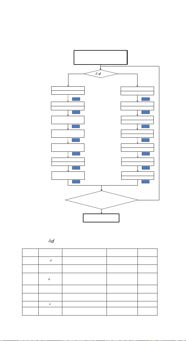
48
Output(WORK1/WORK2) Instruction
WORK1: The P1 heating/cooling output
WORK2: The P2 heating/cooling output
Indicator LED:
●Red LED is on WORK1 output is on.
●Red LED is blinking WORK1 output is performing the
function of compressor delay.
●Green LED is on WORK2 output is on.
●Green LED is blinking WORK2 output is performing the
function of compressor delay.
●Yellow LED is on The controller is in the setting mode.
Button Instruction
Please read the detail on 2.Button Operation Instructions below
Probe interface
Two temperature probes can be insert into P1 and P2 interface.
Temperature probe
●If the controller display Er, you may get a false temperature
probe, please try harder to insert the probe and rotate it to make
good contact. If the problem is still persists, it is likely the
internal probe wire has been damaged by the moisture or heat
temperature.
●The probe and cable cannot be touched by the flame.
●Do not exceed the probe temperature range to avoid
damaging.
2 Button Operation Instructions
2.1 Restore Default Settings
Press and hold the “ " button to power on, the buzzer will
make a short call, indicating that all parameters of the user's
temperature and humidity probe function return to the default
setting value.
2.2 “ ” and “ ”Button Function in Normal Operation
Mode
Press the “ ", PV shows the current temperature setting
value , SV shows current humidification value; press “ ", PV
shows current temperature value, SV the current humidification
setting value , and It will be back to the normal display if there is
no operation for 3 seconds orpressing the "
SET" button.
2.3 “SET” Button Function in Normal Operation Mode
Short press the “
SET” button to enter the quick setting
temperature and humidity value mode. PV shows the current
temperature setting value and flashes, and short press “ ” or
“ ” button to increase or decrease the setting value, long
press “ ” or “ ”button to quickly increase or decrease the
setting value, Short press the “
SET” button again,SV shows
the current humidity setting value and flashes, and short press
“ ” or “ ” button to increase or decrease the setting value,
long press “ ” or “ ”button to quickly increase or decrease
the setting value and lastly press the "
SET" button again to
confirm and exit. If there is no operation, it will automatically
exit after 10 seconds and save the setting value.
2.4 Button Function in Setting Mode
When the controller is working normally, press the “SET” button
for 2 seconds to enter the setting mode,the PV shows the first
menu code“
”, SV shows the corresponding setting value.
Press “
SET” button to scroll down the menu item and save the
parameters of the previous menu item. Press“ ” or
“ ”button to change the current setting value. Selected T to
enter the temperature parameter modification mode; selected H
to enter the humidity parameter modification mode. If in the
setting state, there is no operation within 30 seconds or long
press "
SET" button for 2 seconds, it will exit and save the
setting state and return to normal operation mode.
3.2 Setting Menu Instruction
Y N
Heating or Cooling Mode
Humidificationi or
Dehumidification Mode
Temperature Setting Value
Humidity Setting Value
Heating or Cooling
difference value
Humidificationi or
Dehumidification
difference value
Alarm High
Temperature Limit
Alarm High Humidity Limit
SET SET
Alarm Low
Temperature Limit
Alarm Low Humidity Limit
Compressor Delay Time
Compressor Delay Time
Temperature Calibration
Humidity Calibration
N
Y
Y
Press
"SET" Key for over 2
seconds to enter parameters
setting mode
TS
77.0℉
DS
AH
AL
PT
0Minute
CA
SET
SET
SET
SET
SET
SET
SET
HC
H
No Key for 30 seconds or Presss
"SET" key for over 2 second ?
Working normally
=T?
HS
50.0%RH
DS
5.0%RH
AH
99.0%RH
AL
5.0%RH
PT
0Minute
CA
0.0%RH
SET
SET
SET
SET
SET
SET
SET
HD
H
3 Menu Instruction
3.1 Setting mode Flow Chart
3 .2.1 When is H
Code Symbol Function Setting Range
Default
Setting
HD
Humidification or
Dehumidification Mode
H or D H
HS HS Humidity Setting Value
5.0%RH
~99.0%RH
50%RH
DS
s
Humidification or
Dehumidification Difference
Value
1.0%RH
~20.0%RH
5%RH
AH AH Alarm High Humidity Limit
5.0%RH
~99.0%RH
99.0%RH
AL AL Alarm Low Humidity Limit
5.0%RH
~99.0%RH
5.0%RH
PT Compressor Delay Time
0~10 minutes
0 minute
CA CA Humidity Calibration
-20.0%RH
~20.0%RH
0%RH
H
P

49
Output(WORK1/WORK2) Instruction
WORK1: The P1 heating/cooling output
WORK2: The P2 heating/cooling output
Indicator LED:
●Red LED is on WORK1 output is on.
●Red LED is blinking WORK1 output is performing the
function of compressor delay.
●Green LED is on WORK2 output is on.
●Green LED is blinking WORK2 output is performing the
function of compressor delay.
●Yellow LED is on The controller is in the setting mode.
Button Instruction
Please read the detail on 2.Button Operation Instructions below
Probe interface
Two temperature probes can be insert into P1 and P2 interface.
Temperature probe
●If the controller display Er, you may get a false temperature
probe, please try harder to insert the probe and rotate it to make
good contact. If the problem is still persists, it is likely the
internal probe wire has been damaged by the moisture or heat
temperature.
●The probe and cable cannot be touched by the flame.
●Do not exceed the probe temperature range to avoid
damaging.
2 Button Operation Instructions
2.1 Restore Default Settings
Press and hold the “ " button to power on, the buzzer will
make a short call, indicating that all parameters of the user's
temperature and humidity probe function return to the default
setting value.
2.2 “ ” and “ ”Button Function in Normal Operation
Mode
Press the “ ", PV shows the current temperature setting
value , SV shows current humidification value; press “ ", PV
shows current temperature value, SV the current humidification
setting value , and It will be back to the normal display if there is
no operation for 3 seconds orpressing the "
SET" button.
2.3 “SET” Button Function in Normal Operation Mode
Short press the “
SET” button to enter the quick setting
temperature and humidity value mode. PV shows the current
temperature setting value and flashes, and short press “ ” or
“ ” button to increase or decrease the setting value, long
press “ ” or “ ”button to quickly increase or decrease the
setting value, Short press the “
SET” button again,SV shows
the current humidity setting value and flashes, and short press
“ ” or “ ” button to increase or decrease the setting value,
long press “ ” or “ ”button to quickly increase or decrease
the setting value and lastly press the "
SET" button again to
confirm and exit. If there is no operation, it will automatically
exit after 10 seconds and save the setting value.
2.4 Button Function in Setting Mode
When the controller is working normally, press the “SET” button
for 2 seconds to enter the setting mode,the PV shows the first
menu code“
”, SV shows the corresponding setting value.
Press “
SET” button to scroll down the menu item and save the
parameters of the previous menu item. Press“ ” or
“ ”button to change the current setting value. Selected T to
enter the temperature parameter modification mode; selected H
to enter the humidity parameter modification mode. If in the
setting state, there is no operation within 30 seconds or long
press "
SET" button for 2 seconds, it will exit and save the
setting state and return to normal operation mode.
3.3.2When is T
Code Symbol Function Setting Range
Default
Setting
HC HC
Heating or Cooling
mode
H or C H
TS TS
Temperature Settin
g
Value
-40.0
℃~
100
℃
25.0
℃
-40.0℉~212℉ 77.0℉
DS
Heating or Cooling
Difference Value
0.3℃~15.0℃ 2.0℃
1.0℉~30.0℉ 3.0℉
AH AH
Alarm High
Temperature Limit
-40.0℃~100℃ 100℃
-40.0℉~212℉ 212℉
AL AL
Alarm Low
Temperature Limit
-40.0℃~100℃ -40.0℃
-40.0℉~212℉ -40.0℉
PT
Compressor Delay
Time
0~10 minutes 0 minute
CA CA
Temperature
Calibration
-9.9℃~9.9℃
0.0℃
-15.0℉~15.0℉
0.0℉
CF CF
Fahrenheit or Celsius
Settings
C or F F
4. Control Function Instruction
When the controller is working normally, the PV displays the
measured temperature .Use Heating indicator LED and
Cooling indicator LED to indicate whether the user has chosen
heating or cooling. The SV displays the measured humidity.
Use Humidification indicator LED and Dehumidification
indicator LED to indicate whether the user has chosen
humidification or dehumidification. The WORK1 is output
control of Temperature, furthermore the red led is the WORK1
output status indicator; the WORK2 is the output control of
humidity, furthermore the green led is the WORK2 output
status indicator.
4.1 Temperature Control Function ( HC,TS,DS )
When HC=H, it is heating mode, Heating indicator LED is on.
When PV(measured temperature) ≤ TS(temperature setting
value) – DS(heating or cooling difference setting value),
red led is on, WORK1 output works; when PV (measured
temperature) ≥ TS(temperature setting value),red led is off,
and the WORK1 output is off.
When HC=C, it is cooling mode, Cooling indicator LED is on.
When PV(measured temperature) ≥ TS(temperature setting
value) + DS(heating or cooling difference setting value),red led
is on, and the WORK1 output works; red led flashes, indicating
the cooling device is in the delay protection state; when
PV(measured temperature) ≤ TS(temperature setting value),
red led is off and the WORK1 output is off.
s
P

50
4.2 Humidity Control Function (HD,HS,DS )
When HD=H, it is humidification mode, Humidification
indicator LED is on . When PV(measured humidity) ≤
HS(humidity setting value) – DS(humidification or dehumidifi-
cation difference setting value),green led is on, WORK2 output
works; when PV(measured humidity) ≥ HS(humidity setting
value),green led is off, and the WORK2 output is off.
When HD=D, it is dehumidification mode, Dehumidification
indicator LED is on. When SV(measured humidity) ≥
HS(humidity setting value) + DS(humidification or dehumidifi-
cation difference setting value),green led is on, and the
WORK2 output works; green led is blinking , indicating the
dehumidification device is in the delay protection state; when
SV(measured humidity) ≤ HS(humidity setting value), green
led is off and the WORK2 output is off.
4.3 Alarm High / Low Temperature Limit Settings(AH,AL)
When measured temperature ≥ AH, high temperature limit
alarm, PV shows alternate AH with current temperature ,
buzzer will “bi-bi-Biii” alarm, until the temperature <AH, buzzer
off and return to normal display and control. Or press the
button to turn the buzzer alarm off only.
When measured temperature ≤ AL, low temperature limit
alarm, PV shows alternate AL with current temperature, buzzer
will “bi-bi-Biii” alarm, until the temperature >AL, buzzer off and
return to normal display and control. Or press the button to
turn the buzzer alarm off only.
4.4 Alarm High / Low Humidity Limit Settings (AH,AL)
When measured humidity ≥ AH, high humidity limit alarm, SV
shows alternate AH with current humidity, buzzer will
“bi-bi-Biii” alarm, until the humidity <AH, buzzer off and return
to normal display and control. Or press the button to turn the
buzzer alarm off only.
When measured humidity ≤ AL, low humidity limit alarm, PV
shows alternate AL with current humidity, buzzer will
“bi-bi-Biii” alarm, until the humidity <AL, buzzer off and return
to normal display and control. Or press the button to turn the
buzzer alarm off only.
4.5 Cooling /Dehumidification Delay Protection Time(PT)
In cooling mode,when the power is turned on for the first
time, it will not start the cooling immediately when PV(mea-
sured temperature value) ≥TS(temperature setting
value)+DS(heating or cooling difference value),but waiting for
Output(WORK1/WORK2) Instruction
WORK1: The P1 heating/cooling output
WORK2: The P2 heating/cooling output
Indicator LED:
●Red LED is on WORK1 output is on.
●Red LED is blinking WORK1 output is performing the
function of compressor delay.
●Green LED is on WORK2 output is on.
●Green LED is blinking WORK2 output is performing the
function of compressor delay.
●Yellow LED is on The controller is in the setting mode.
Button Instruction
Please read the detail on 2.Button Operation Instructions below
Probe interface
Two temperature probes can be insert into P1 and P2 interface.
Temperature probe
●If the controller display Er, you may get a false temperature
probe, please try harder to insert the probe and rotate it to make
good contact. If the problem is still persists, it is likely the
internal probe wire has been damaged by the moisture or heat
temperature.
●The probe and cable cannot be touched by the flame.
●Do not exceed the probe temperature range to avoid
damaging.
2 Button Operation Instructions
2.1 Restore Default Settings
Press and hold the “ " button to power on, the buzzer will
make a short call, indicating that all parameters of the user's
temperature and humidity probe function return to the default
setting value.
2.2 “ ” and “ ”Button Function in Normal Operation
Mode
Press the “ ", PV shows the current temperature setting
value , SV shows current humidification value; press “ ", PV
shows current temperature value, SV the current humidification
setting value , and It will be back to the normal display if there is
no operation for 3 seconds orpressing the "
SET" button.
2.3 “SET” Button Function in Normal Operation Mode
Short press the “
SET” button to enter the quick setting
temperature and humidity value mode. PV shows the current
temperature setting value and flashes, and short press “ ” or
“ ” button to increase or decrease the setting value, long
press “ ” or “ ”button to quickly increase or decrease the
setting value, Short press the “
SET” button again,SV shows
the current humidity setting value and flashes, and short press
“ ” or “ ” button to increase or decrease the setting value,
long press “ ” or “ ”button to quickly increase or decrease
the setting value and lastly press the "
SET" button again to
confirm and exit. If there is no operation, it will automatically
exit after 10 seconds and save the setting value.
2.4 Button Function in Setting Mode
When the controller is working normally, press the “SET” button
for 2 seconds to enter the setting mode,the PV shows the first
menu code“
”, SV shows the corresponding setting value.
Press “
SET” button to scroll down the menu item and save the
parameters of the previous menu item. Press“ ” or
“ ”button to change the current setting value. Selected T to
enter the temperature parameter modification mode; selected H
to enter the humidity parameter modification mode. If in the
setting state, there is no operation within 30 seconds or long
press "
SET" button for 2 seconds, it will exit and save the
setting state and return to normal operation mode.

51
a delay time(PT).
When two adjacent of cooling starting intervals are greater
than the delay time, it will immediately start cooling ; When two
adjacent of cooling starting intervals are less than the delay
time, it needs to operate the remaining delay time to start the
cooling.
Delay time will start counting from the WORK1 output off.
In dehumidification mode,when the power is turned on for
the first time, it will not start dehumidification immediately
when SV(measured humidity value) ≥HS(humidity setting
value)+DS(humidification or dehumidification difference
value),but waiting for a delay time(PT).
When two adjacent of dehumidification starting intervals are
greater than the delay time, it will immediately start dehumidi-
fication ; When two adjacent of dehumidification starting
intervals are less than the delay time, it needs to operate the
remaining delay time to start dehumidification .
Delay time will start counting from the WORK2 output off.
4.6 Temperature and Humidity Calibration (CA)
When the measured temperature or humidity deviates from the
standard temperature or humidity, the temperature or humidity
calibration function can be used to make the measured the
value of the instrument consistent with the standard value.
The calibrated temperature or humidity is equal to the
measured temperature or measured humidity value + the
calibration value.
4.7 Fahrenheit or Celsius Settings (CF)
The user can set the display unit to Fahrenheit or Celsius
according to their habits. P1 temperature mode display unit is
Fahrenheit or Celsius, the default is Fahrenheit. If you need to
display the unit in Celsius, then set the CF to C. Please note
that when the CF changes state, all setting values are restored
to the default setting and the buzzer gives a short beeping
prompt.
Output(WORK1/WORK2) Instruction
WORK1: The P1 heating/cooling output
WORK2: The P2 heating/cooling output
Indicator LED:
●Red LED is on WORK1 output is on.
●Red LED is blinking WORK1 output is performing the
function of compressor delay.
●Green LED is on WORK2 output is on.
●Green LED is blinking WORK2 output is performing the
function of compressor delay.
●Yellow LED is on The controller is in the setting mode.
Button Instruction
Please read the detail on 2.Button Operation Instructions below
Probe interface
Two temperature probes can be insert into P1 and P2 interface.
Temperature probe
●If the controller display Er, you may get a false temperature
probe, please try harder to insert the probe and rotate it to make
good contact. If the problem is still persists, it is likely the
internal probe wire has been damaged by the moisture or heat
temperature.
●The probe and cable cannot be touched by the flame.
●Do not exceed the probe temperature range to avoid
damaging.
2 Button Operation Instructions
2.1 Restore Default Settings
Press and hold the “ " button to power on, the buzzer will
make a short call, indicating that all parameters of the user's
temperature and humidity probe function return to the default
setting value.
2.2 “ ” and “ ”Button Function in Normal Operation
Mode
Press the “ ", PV shows the current temperature setting
value , SV shows current humidification value; press “ ", PV
shows current temperature value, SV the current humidification
setting value , and It will be back to the normal display if there is
no operation for 3 seconds orpressing the "
SET" button.
2.3 “SET” Button Function in Normal Operation Mode
Short press the “
SET” button to enter the quick setting
temperature and humidity value mode. PV shows the current
temperature setting value and flashes, and short press “ ” or
“ ” button to increase or decrease the setting value, long
press “ ” or “ ”button to quickly increase or decrease the
setting value, Short press the “
SET” button again,SV shows
the current humidity setting value and flashes, and short press
“ ” or “ ” button to increase or decrease the setting value,
long press “ ” or “ ”button to quickly increase or decrease
the setting value and lastly press the "
SET" button again to
confirm and exit. If there is no operation, it will automatically
exit after 10 seconds and save the setting value.
2.4 Button Function in Setting Mode
When the controller is working normally, press the “SET” button
for 2 seconds to enter the setting mode,the PV shows the first
menu code“
”, SV shows the corresponding setting value.
Press “
SET” button to scroll down the menu item and save the
parameters of the previous menu item. Press“ ” or
“ ”button to change the current setting value. Selected T to
enter the temperature parameter modification mode; selected H
to enter the humidity parameter modification mode. If in the
setting state, there is no operation within 30 seconds or long
press "
SET" button for 2 seconds, it will exit and save the
setting state and return to normal operation mode.
Inkbird Tech.C.L
www.ink-bird.com
+86-755-25738050
Shenzhen,GD,518000,China