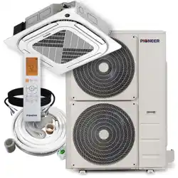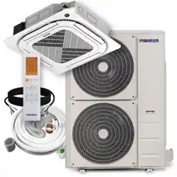
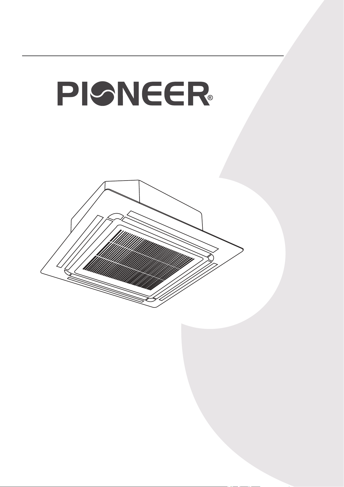
CYB-20 Inverter Series
For 36,000-48,000 BTU/hr Systems
Quantum Ultra (R-454B) - CB Indoor and YN Outdoor
Installation &
User Manual
IMPORTANT NOTICE:
Read this manual carefully before installing or
operating your new air conditioning system. Be
sure to save this manual for future reference.
DUCTLESS MINI SPLIT SYSTEM AIR CONDITIONER / HEAT PUMP
1
Table of Contents
Air Conditioner Installation & User Manual
Read this Manual
The manual provides helpful hints on using and maintaining the air conditioner properly. Performing preventive care can save time and
money over the lifespan of the air conditioner. These instructions may not cover every possible condition of use, so common sense and
attention to safety is required when installing, operating, and maintaining this product.
2
1 Safety Precautions........................... 3
2 Product Overview.............................
16
3 Unpacking & Packing.......................
24
65
4 Installation Overview........................ 25
5 Installation........................................ 28
6
Leak Checks & Test Run.................
7 Operating Instructions...................... 68
8 Maintenance..................................... 70
T Troubleshooting................................ 75
Air Conditioner Installation & User Manual
Safety Precautions
1
It is important to read this section before operating and installing the system. Incorrect installation due to
ignoring instructions can cause serious damage or injury. The seriousness of potential damage and injuries
is classified as either a warning or caution.
Explanation of Symbols
WARNING
This symbol indicates the possibility of personal injury or loss of life.
CAUTION
This symbol indicates the possibility of property damage or serious consequences.
WARNING
Children aged 8 and above, as well as individuals with lack of experience or reduced physical, sensory, or
mental capabilities can use the appliance if supervision or instruction is given. Do not allow children to play with
or near the appliance. Children or untrained personnel should be restricted from cleaning and performing
maintenance on the appliance, unless they're given supervision.
WARNINGS FOR PRODUCT USE
• Turn off the air conditioner and disconnect the power before cleaning, installing, or repairing the system.
Failure to do so can cause electric shock.
• If an abnormal situation arises (such as a burning smell), immediately turn off the unit and disconnect the
power. Call the dealer for instructions to avoid electrical shock, fire, or injury.
• Do not insert fingers, rods, or other objects into the air inlet or outlet. This could cause injury because the fan
rotates at high speeds.
• Do not use flammable sprays such as hair spray, lacquer, or paint near the unit. This could cause fire or
combustion.
• Do not operate the air conditioner in locations near or around combustible gases. Emitted gas may collect
around the unit and cause an explosion.
• Do not operate the air conditioner in a wet room such as a bathroom or laundry room. Too much exposure to
water can cause electrical components to short circuit.
• Do not expose your body directly to cool air for prolonged durations of time.
• If the air conditioner is used together with burners or other heating devices, thoroughly ventilate the room to
avoid oxygen deficiency.
• In certain functional environments (such as kitchens, server rooms, etc.), it is highly recommended to use
specifically designed air-conditioning units.
3
Air Conditioner Installation & User Manual
Safety Precautions
1
WARNINGS FOR PRODUCT INSTALLATION
• Turn off the air conditioner and disconnect its power supply before installing or repairing the system. Failure to
do so can cause electric shock.
• An authorized dealer or specialist must perform the installation. Incorrect installation can cause water leakage,
electrical shock, or fire.
• Perform the installation according to the instructions in this manual. Improper installation can cause water
leakage, electrical shock, or fire.
• Contact an authorized service technician to maintain and repair the unit.
• Install the appliance in accordance with national wiring regulations. Only use the included accessories, parts,
and specified parts for installation. Using non-standard parts can cause water leakage, electrical shock, fire, or
unit failure.
• Install the unit in a firm location that can support the unit's weight. If the chosen location cannot support the
unit's weight or the installation is done incorrectly, the unit may drop and cause serious injury or damage.
• For units with an auxiliary electric heater, do not install the unit within 3 feet (1 m) of any combustible materials.
• For units that have a wireless network function (USB device access replacement), professional staff must carry
out the maintenance operations.
• Do not install the unit in a location that may be exposed to combustible gas leaks. If combustible gas
accumulates around the unit, it could cause fire.
• Do not turn on the power until all work has been completed.
• When moving or relocating the air conditioner, consult experienced service technicians for the disconnection
and reinstallation of the unit.
ELECTRICAL WARNINGS
• Only use the specified wire. If the wire is damaged, it must be replaced by the manufacturer, service agent, or
a similarly qualified individual in order to avoid a hazard.
• Properly ground the product during installation to avoid electrical shock.
• Incorporate disconnections in the fixed wiring, according to the wiring rules.
• Do not share the electrical outlet with other appliances. Improper or insufficient power supply can cause fire or
electric shock.
4
Air Conditioner Installation & User Manual
Safety Precautions
1
• For all electrical work, follow the local and national wiring standards, regulations, and installation manual.
Connect the cables tightly, then clamp them securely to prevent external forces from damaging the terminal.
Improper electrical connections can result in electrical shock or fire. Complete the electrical connections
according to the Electrical Connection diagrams located on the panels of the indoor and outdoor units.
• Properly arrange all wiring to ensure the control board cover can close correctly. If the control board cover is
not closed properly, it can lead to corrosion and cause the connection points on the terminal to heat up and
catch fire. It can also cause electrical shock.
• If connecting power to fixed wiring, incorporate an all-pole disconnection device in the fixed wiring. Ensure the
device is in accordance with the wiring rules.
• Turn off the air conditioner and disconnect the power if the unit will not be used for a long duration of time.
• Turn off and unplug the unit during storms.
• Make sure that water condensation can drain unhindered from the unit.
• Do not operate the air conditioner with wet hands. This may cause electrical shock.
• Do not use the device for any other purpose than its intended use.
• Do not climb onto or place objects on top of the outdoor unit.
• Do not allow the air conditioner to operate for long periods of time with doors or windows open, or if the
humidity is considerably high.
Fuse Specifications
The air conditioner's circuit board (PCB) is designed with a fuse to provide overcurrent protection. The
specifications of the fuse are printed on the circuit board. For example: T3.15AL/250VAC, T5AL/250VAC,
T3.15A/250VAC, T5A/250VAC, T20A/250VAC, T30A/250VAC, etc.
Only use the blast-proof ceramic fuse.
CAUTION
CLEANING & MAINTENANCE WARNINGS
• Turn off the device and disconnect its
power supply
before cleaning. Failure to do so can cause an electrical
shock.
• Do not clean the air conditioner with excessive amounts of water.
• Do not clean the air conditioner with combustible cleaning agents. Combustible cleaning agents can cause
fire or deformation.
5
Air Conditioner Installation & User Manual
Safety Precautions
1
WARNING FOR USING FLAMMABLE REFRIGERANTS
• Do not use means to accelerate the defrosting and cleaning processes, other than those recommended by
the manufacturer.
• Store the appliance in a room without continuously operating ignition sources. For example: open flames, an
operating gas appliance, or an operating electric heater.
• Do not pierce or burn.
• Be aware that refrigerants may not contain an odor.
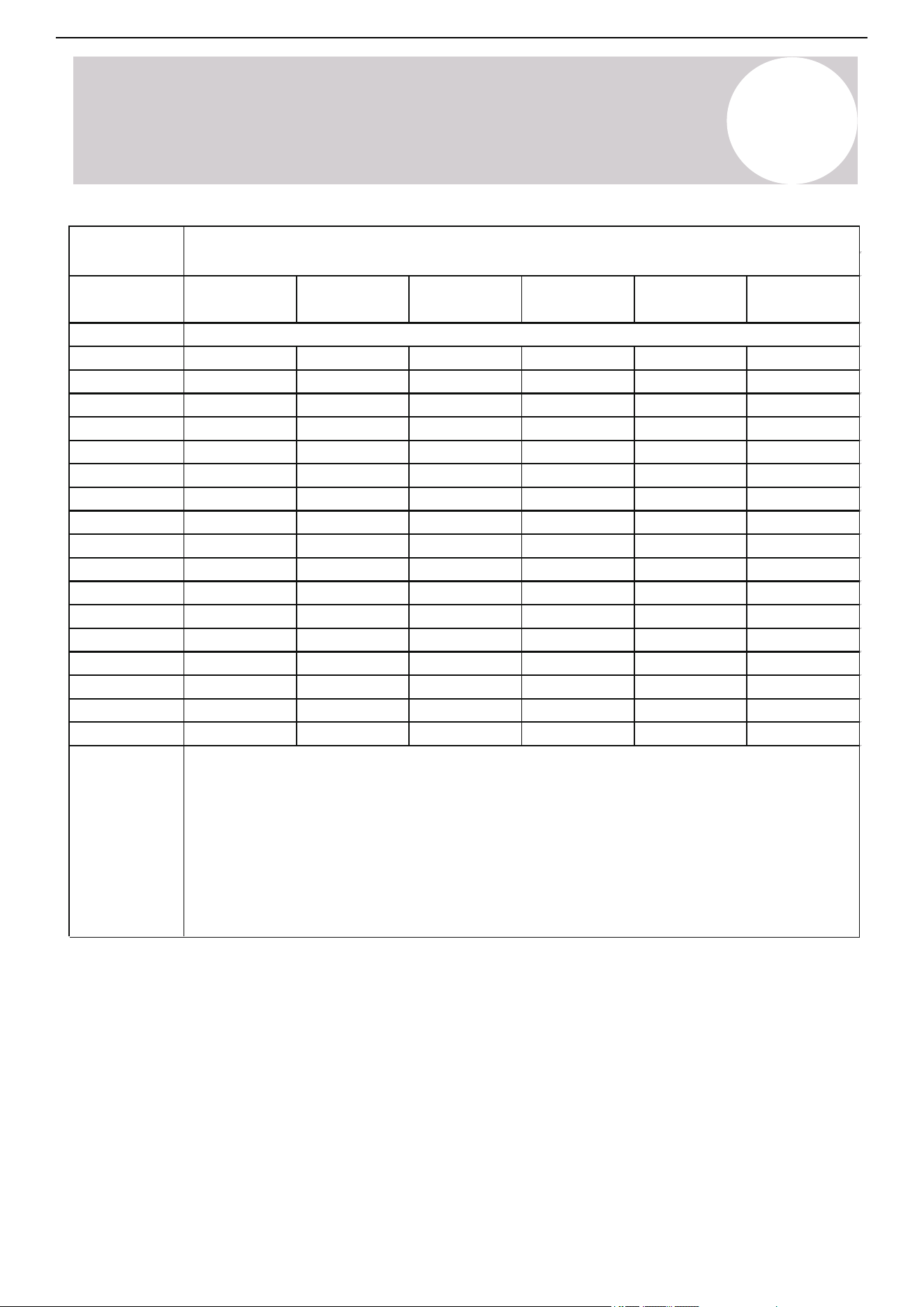
R-454B refrigerant charge amount and minimum room area:
The machine you purchased may be one of the types listed in the table below. The indoor and outdoor units are
designed to be used together. Check the machine that was purchased. Install the indoor unit at least 7-feet, 6-½-
inches (2.3 m) above the floor. The height of the room cannot be less than the indoor unit's installed height. The
minimum room area for operation or storage is as specified in the following table:
For the units with refrigerant sensors, when the unit detects a refrigerant leak, the minimum airflow of the indoor
unit is as follows:
Model
36K
48K
1,770m³/h
2,100m³/h
1,042CFM
1,236CFM
Indoor Nominal
Air Volume
6
m
c
or m
REL
[ozs/kg]
7.6/2.3 7.9/2.4 8.6/2.6 9.2/2.8
<=62.6/1.776
Area
formula
h
inst
[ft/m]
12/1.10
63.4/1.8
70.5/2.0
77.5/2.2
84.6/2.4
91.7/2.6
98.7/2.8
105.8/3.0
112.8/3.2
119.9/3.4
126.9/3.6
134/3.8
141.0/4.0
148.1/4.2
155.1/4.4
162.2/4.6
169.2/4.8
176.3/5.0
47/4.35
52/4.83
58/5.31
63/5.80
68/6.28
73/6.76
78/7.24
84/7.73
89/8.21
94/8.69
99/9.17
104/9.66
110/10.14
115/10.62
120/11.11
125/11.59
130/12.07
51/4.68
56/5.20
62/5.72
68/6.24
73/6.76
79/7.28
84/7.80
90/8.32
96/8.84
101/9.36
107/9.88
118/10.92
124/11.44
129/11.96
135/12.48
140/13.00
55/5.07
61/5.64
67/6.20
73/6.76
79/7.32
85/7.89
91/8.45
97/9.01
104/9.58
110/10.14
122/11.27
128/11.83
134/12.39
140/12.96
146/13.52
152/14.08
6.0~7.3/
1.8~2.2
60/5.53
67/6.15
73/6.76
80/7.38
86/7.99
93/8.60
100/9.22
106/9.83
113/10.45
120/11.06
126/11.68
133/12.29
139/12.90
146/13.52
153/14.13
159/14.75
166/15.36
57/5.29
64/5.88
70/6.47
83/7.64
89/8.23
95/8.82
102/9.41
108/9.99
114/10.58
121/11.17
127/11.76
133/12.34
140/12.93
146/13.52
152/14.11
159/14.69
76/7.06
9.9/3.0
44/4.06
49/4.51
54/4.96
59/5.41
64/5.86
68/6.31
73/6.76
78/7.21
83/7.66
88/8.11
93/8.56
97/9.01
102/9.46
107/9.91
112/10.37
117/10.82
122/11.27
112/10.40
116/10.70
Air Conditioner Installation & User Manual
Safety Precautions
1
A
min
[ft
2
/ m
2
]
• A
min
is the required minimum room area in ft
2
/m
2
.
• M
c
is the actual refrigerant charge in the system in oz/kg
• M
REL
is the refrigerant releasable charge in oz/kg (applicable to the units with refrigerant
sensors only)
• h
inst
is the height of the bottom of the appliance relative to the floor of the room after
installation.
WARNING: The minimum room area or minimum room of conditioner space is based on the
releasable charge and total system refrigerant charge.
7

Air Conditioner Installation & User Manual
Safety Precautions
1
1. Installation (Where refrigerant pipes are allowed)
• Any individual who is involved with working on or breaking into a refrigerant circuit must hold a valid certificate
from an industry-accredited assessment authority. The certificate authorizes the individual's competence for
handling refrigerants safely in accordance with the specifications of an industry recognized assessment.
• Maintenance and repairs requiring the assistance of other skilled personnel must be carried out under the
supervision of the individual competent in the use of flammable refrigerants.
• Keep the installation of the pipe-work to a minimum.
• Protect the pipe-work from physical damage.
• Ensure the refrigerant pipes comply with national gas regulations.
• Ensure the mechanical connections are accessible for maintenance purposes.
• Do not allow foreign matter (oil, water, etc.) from entering the piping. In addition, when storing the piping,
securely seal the opening by pinching, taping, etc.
• Competent individuals must carry out all working procedures that affect safety.
• Store the appliance in a well-ventilated area where the room size corresponds to the room area as specified
for operation.
• Test the joints using detection equipment with a capability of 5g/year of refrigerant or better. After installation,
ensure the equipment is at a standstill and maintained under operating pressure, or at least the minimum
standstill pressure.
• In cases that require mechanical ventilation, ensure the ventilation openings are kept clear of obstruction.
• Leak Detection System Installed: Power the unit except for service. For units with refrigerant sensors, if a leak
is detected, the indoor unit will display an error code and buzz, the outdoor compressor will stop immediately,
and the indoor fan will run. The refrigerant sensor's service life is 15 years. When the refrigerant sensor
malfunctions, the indoor unit will display the "FHCC" error code. The refrigerant sensor cannot be repaired
and can only be replaced by the manufacturer. Replace the sensor with one specified by the manufacturer.
This is only applicable for units with refrigerant sensors.
8

Air Conditioner Installation & User Manual
Safety Precautions
1
• Protect the piping material and pipe routing from physical damage during operation and service. Ensure the
piping material and pipe routing are in compliance with national and local codes and standards, such as
ASHRAE 15, IAPMO Uniform Mechanical Code, ICC International Mechanical Code, or CSA B52. All field
joints must be accessible for inspection prior to being covered or enclosed.
• Protect piping, fittings, and protection devices from adverse environmental effects. For example, water
collecting and freezing in relief pipes or the accumulation of dirt and debris.
• Ensure the piping in the refrigerant system is designed and installed to minimize the likelihood of hydraulic
shock damaging the system.
• Before applying any insulation, protect the steel pipes and components against corrosion with a rustproof
coating.
• Take precautions to avoid excessive vibration or pulsation.
• The minimum floor area of the room is mentioned in the form of a table or single figure without reference to a
formula.
• After completing the field piping for split systems, pressure test the field pipework with an inert gas. Then,
vacuum test the pipework before refrigerant charging. Ensure the testing is completed according to the
following requirements:
a. The minimum test pressure for both the high and low sides must match their respective design pressures,
unless the high side cannot be isolated from the low side. If the high side cannot be isolated from the low side
of the system, the entire system must be pressure tested to the low-side design pressure.
b. After removing the pressure source, maintain the test pressure for at least 1 hour, ensuring there is no
decrease of pressure, which is indicated by the test gauge. Ensure the test gauge resolution does not exceed
5% of the test pressure.
c. During the evacuation test, after achieving a vacuum level specified in the manual, isolate the refrigeration
system from the vacuum pump and ensure the pressure does not rise above 1,500 microns within 10 minutes.
The appropriate vacuum pressure level is specified in the manual, and must not be less than 500 microns or
the value required for compliance with national and local codes and standards. The codes and standards may
vary between residential, commercial, and industrial buildings.
• Field-made refrigerant indoor joints must be tightness tested according to the following requirements: The test
method must have a sensitivity of 5 grams per year of refrigerant or better under a pressure of at least 0.25
times the maximum allowable pressure. No leak should be detected.
2. When using a flammable refrigerant, the requirements for the installation space and ventilation are
determined by the following criteria:
o Mass charge amount (M) used in the appliance.
o Installation location.
o Ventilation type of the location or appliance.
9

Air Conditioner Installation & User Manual
Safety Precautions
1
3. Qualification of Workers
The working personnel must be qualified to perform any maintenance, service, and repair operations. Competent
individuals must carry out working procedures that affect safety means. The competent individual must complete
the training by national training organizations or manufacturers that are accredited to teach the relevant national
competency standards set in legislation. The individual's competence must be documented by a certificate. All
training must follow the ANNEX HH requirements of UL 60335-2-40 4th Edition.
Examples for such working procedures are:
o Breaking into the refrigerating circuit.
o Opening sealed components.
o Opening ventilated enclosures.
4. Cabling
Confirm the cabling will not be subject to wear, corrosion, excessive pressure, vibration, sharp edges, or any
other adverse environmental effects. The check should also take into account the effects of aging or continual
vibration from sources such as compressors or fans.
Servicing Information
1. Inspect the Area
Before working on systems containing flammable refrigerants, safety checks are required to ensure the risk of
ignition is minimized.
2. Work Procedure
To minimize the risk of flammable gas or vapor presence, conduct work using controlled procedures.
3. General Work Area
Inform all maintenance staff and individuals working in the local area about the nature of the work being
performed. Avoid working in confined spaces. Section off the area around the workspace. Ensure the area is
safe by controlling the flammable materials.
4. Check for Refrigerant
Check the area with an appropriate refrigerant detector before and during work to ensure the technician is aware
of potentially flammable atmospheres. Ensure the leak detection equipment is suitable for flammable
refrigerants, i.e. non-sparking, adequately sealed, or intrinsically safe.
5. Fire Extinguisher
If conducting hot work on the refrigeration equipment or any associated parts is needed, appropriate fire
extinguishing equipment must be available. Keep a dry powder or CO
2
fire extinguisher adjacent to the charging
area.
6. No Ignition Sources
Individuals carrying out work involving exposed pipework on a refrigerant system are prohibited from using any
sources of ignition that may lead to a risk of fire or explosion. All possible ignition sources, such as cigarette
smoking, must be performed at a sufficient distance from the installation or maintenance site. Before conducting
work on the equipment, the surrounding area must be surveyed to ensure there are no flammable hazards or
ignition risks. No Smoking signs must be displayed.
7. Well-Ventilated Area
Ensure the area is open and well-ventilated before accessing the system or performing any work that generates
heat. Ventilation must be maintained to a certain degree while work is being carried out. The ventilation should
safely disperse any released refrigerant and expel it externally into the atmosphere.
10

Air Conditioner Installation & User Manual
Safety Precautions
1
8. Inspect the Refrigeration Equipment
When changing electrical components, they must be fit-for-purpose and meet the correct specifications. Follow
the manufacturer's maintenance and service guidelines at all times. If in doubt, consult the manufacturer's
technical department for assistance.
For installations using flammable refrigerants, check the following:
o Ensure the charge size is appropriate for the room in which the refrigerant-containing parts are installed.
o Confirm the ventilation machinery and outlets are operating adequately and not obstructed.
o If an indirect refrigerating circuit is being used, check the secondary circuit for the presence of refrigerant.
o Confirm the equipment markings are visible and legible. Correct markings and signs that are illegible.
o Install the refrigeration pipe or components in a position that minimizes the risk of corrosion from harmful
substances, unless constructed of corrosion-resistant materials and suitably protected.
9. Inspect the Electrical Devices
Repairing and maintaining electrical components must include initial safety checks and component inspections.
If a fault exists that could compromise safety, do not connect the electrical supply to the circuit until the fault is
resolved. If the fault cannot be immediately corrected but it is necessary to continue operation, a temporary
solution must be implemented. If a temporary solution is implemented, it must be reported to the owner of the
equipment, ensuring both parties are informed.
Initial safety checks must include the following:
10. Replace Sealed Electrical Components If Damaged.
11. Replace Intrinsically Safe Components If Damaged.
12. Cabling
Confirm the cabling will not be subject to wear, corrosion, excessive pressure, vibration, sharp edges, or any
other adverse environmental effects. The check should also take into account the effects of aging or continual
vibration from sources such as compressors or fans.
o Confirm the capacitors are discharged. Ensure that this is done in a safe manner to avoid the possibility of
sparking.
o Ensure that no live electrical components and wiring are exposed while charging, recovering, or purging the
system.
o Confirm there is continuity of earth bonding.
11

Air Conditioner Installation & User Manual
Safety Precautions
1
13. Detection of Flammable Refrigerants
Do not use potential sources of ignition for searching or detecting refrigerant leaks. Do not use a halide torch or
detector using a naked flame. Ensure the detector is not a potential source of ignition and is suitable for the
refrigerant used. Leak detection equipment must be set at a percentage of the refrigerant LFL, and calibrated to
the refrigerant employed. Confirm the appropriate percentage of gas (25% maximum).
The following leak detection methods are deemed acceptable for refrigerant systems:
Electronic leak detectors: This detector can detect refrigerant leaks. However, in the case of flammable
refrigerants, the sensitivity may not be adequate and need recalibration. Calibrate the detection equipment in a
refrigerant-free area.
Leak detection fluids: The bubble method and fluorescent method agents are examples of leak detection fluids.
These are suitable to use with most refrigerants. Avoid using detergents containing chlorine as the chlorine may
react with the refrigerant and corrode the copper pipe-work.
If a leak is suspected, remove or extinguish all naked flames.
If a refrigerant leak is found and requires brazing, recover all the refrigerant from the system or use the shut off
valves to isolate the refrigerant in a part of the system remote from the leak.
14. Removal & Evacuation
Use conventional procedures when breaking into the refrigerant circuit. However, for flammable refrigerants, it is
important to follow this best practice since flammability is a consideration.
Follow this procedure:
o Safely remove refrigerant following local and national regulations.
o Evacuate.
o Purge the circuit with inert gas (optional for A2L).
o Evacuate (optional for A2L).
o Continuously flush or purge with inert gas when using a flame to open the circuit.
o Open the circuit.
Recover the refrigerant charge into the correct recovery cylinders if venting is not allowed by local and national
codes. For appliances containing flammable refrigerants, purge the system with oxygen-free nitrogen to render
the appliance safe from flammable refrigerants. If needed, repeat this process several times. Do not use
compressed air or oxygen to purge refrigerant systems.
For appliances containing flammable refrigerants, purge the refrigerant by breaking the vacuum in the system
with oxygen-free nitrogen and continuing to fill until the working pressure is achieved. Then, vent to atmosphere
and finally pull down to a vacuum (optional for A2L). Repeat this process until no refrigerant is within the system
(optional for A2L). When using oxygen-free nitrogen, vent the system down to atmospheric pressure to enable
work to take place. Ensure the outlet for the vacuum pump is not close to any potential ignition sources and
ventilation is available.
12

Air Conditioner Installation & User Manual
Safety Precautions
1
15. Charging Procedures
In addition to conventional charging procedures, follow these requirements:
o Use only appropriate tools when completing work. In case of uncertainty, consult the manufacturer of the
tools for use with flammable refrigerants.
o Ensure the contamination of different refrigerants does not occur when using charging equipment. Hoses or
lines must be as short as possible to minimize the amount of refrigerant contained in them.
o Keep the cylinders upright.
o Ensure the refrigerant system is earthed before charging the system with refrigerant.
o Label the system when charging is complete (if not already).
o Take extreme care to not overfill the refrigeration system.
o Prior to recharging the system, it must be pressure tested with oxygen-free nitrogen. Leak test the system
after completing the charging but prior to commissioning. Carry out a follow-up leak test before leaving the
site.
16. Decommissioning
Before carrying out this procedure, it is essential that the technician is completely familiar with the equipment
and all its details. It is recommended good practice that all refrigerants are recovered safely. Prior to carrying out
the task, take an oil and refrigerant sample in case an analysis is required prior to re-using the recovered
refrigerant. It is essential that electrical power is available before the task is commenced.
a) Become familiar with the equipment and its operations.
b) Isolate the system electrically.
c) Before attempting the procedure ensure that:
o Mechanical handling equipment is available for handling refrigerant cylinders.
o All personal protective equipment is available and being used correctly.
o A competent individual is supervising the recovery process at all times.
o Recovery equipment and cylinders conform to the appropriate standards.
13

Air Conditioner Installation & User Manual
Safety Precautions
1
17. Labeling
Label the equipment stating that it has been de-commissioned and emptied of refrigerant. Make sure to date and
sign the label. For appliances containing flammable refrigerants, ensure there are labels on the equipment
stating it contains flammable refrigerant.
18. Recovery
When removing refrigerant from a system, either for servicing or decommissioning, it is recommended good
practice to remove refrigerants safely. When transferring refrigerant into cylinders, ensure that only appropriate
refrigerant recovery cylinders are employed. Ensure the correct number of cylinders for holding the total system
charge are available. Designate all the cylinders intended to be used for the recovered refrigerant and label them
for that refrigerant (i.e., special cylinders for the recovery of refrigerant). Cylinders must be complete with
pressure-relief valves. The associated shut-off valves must be in working order. Evacuate empty recovery
cylinders and, if possible, allow them to cool before recovery occurs.
The recovery equipment must be in working condition with a set of instructions concerning the equipment that is
at hand. In addition, the recovery equipment must be suitable for the recovery of the flammable refrigerant. If in
doubt, consult the manufacturer. In addition, a set of calibrated weighing scales must be available and in
working order. Hoses must be complete with leak-free disconnect couplings and in good condition.
The recovered refrigerant must be processed according to local legislation in the correct recovery cylinder. In
addition, the relevant waste transfer note must be arranged. Do not mix refrigerants in the recovery unit and
especially not in the cylinders.
When removing compressors or oils, ensure they are evacuated to a level that prevents flammable refrigerant
from remaining in the lubricant. The compressor body must not be heated by an open flame or other ignition
sources to accelerate this process. When oil is drained from a system, it must be carried out safely.
d) Pump down the refrigerant system, if possible.
e) If a vacuum is not possible, make a manifold so that the refrigerant can be removed from various parts of the
system.
f) Make sure the cylinder is situated on the scales before recovery takes place.
g) Start the recovery machine and operate it in accordance with the instructions.
h) Do not overfill cylinders (no more than 80% volume liquid charge).
i) Do not exceed the maximum working pressure of the cylinder, even temporarily.
j) When the cylinders have been filled correctly and the process is completed, make sure the cylinders and
equipment are removed from the site promptly and all isolation valves on the equipment are closed off.
k) Do not charge recovered refrigerant into another refrigeration system, unless it has been cleaned and
checked.
14
Air Conditioner Installation & User Manual
Safety Precautions
1
CAUTION
WARNING
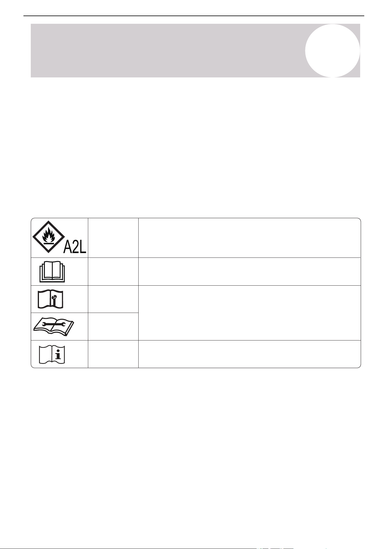
This symbol shows that this appliance uses a flammable
refrigerant. If the refrigerant is leaked and exposed to an
external ignition source, there is a risk of fire.
This symbol shows that the operation manual should be read
carefully.
This symbol shows that information is available such as
the operating manual or installation manual.
This symbol shows that a service personnel should be
handling this equipment with reference to this manual.
Explanation of symbols displayed on the indoor or outdoor units
CAUTION
CAUTION
CAUTION
19. Transportation, Marking, & Storage for Units
o Transport equipment containing flammable refrigerants (Compliance with the transport regulations).
o Mark the equipment using signs (Compliance with local regulations).
o Dispose of equipment using flammable refrigerants (Compliance with national regulations).
o Store the equipment/appliance (Compliance with the manufacturer's instructions).
o Store packed (unsold) equipment. Construct the storage package protection in a way that potential
mechanical damage to the equipment inside the package will not cause a leak of the refrigerant charge.
Local regulations determine the maximum amount of equipment permitted to be stored together.
15
Air Conditioner Installation & User Manual
Product Overview
2
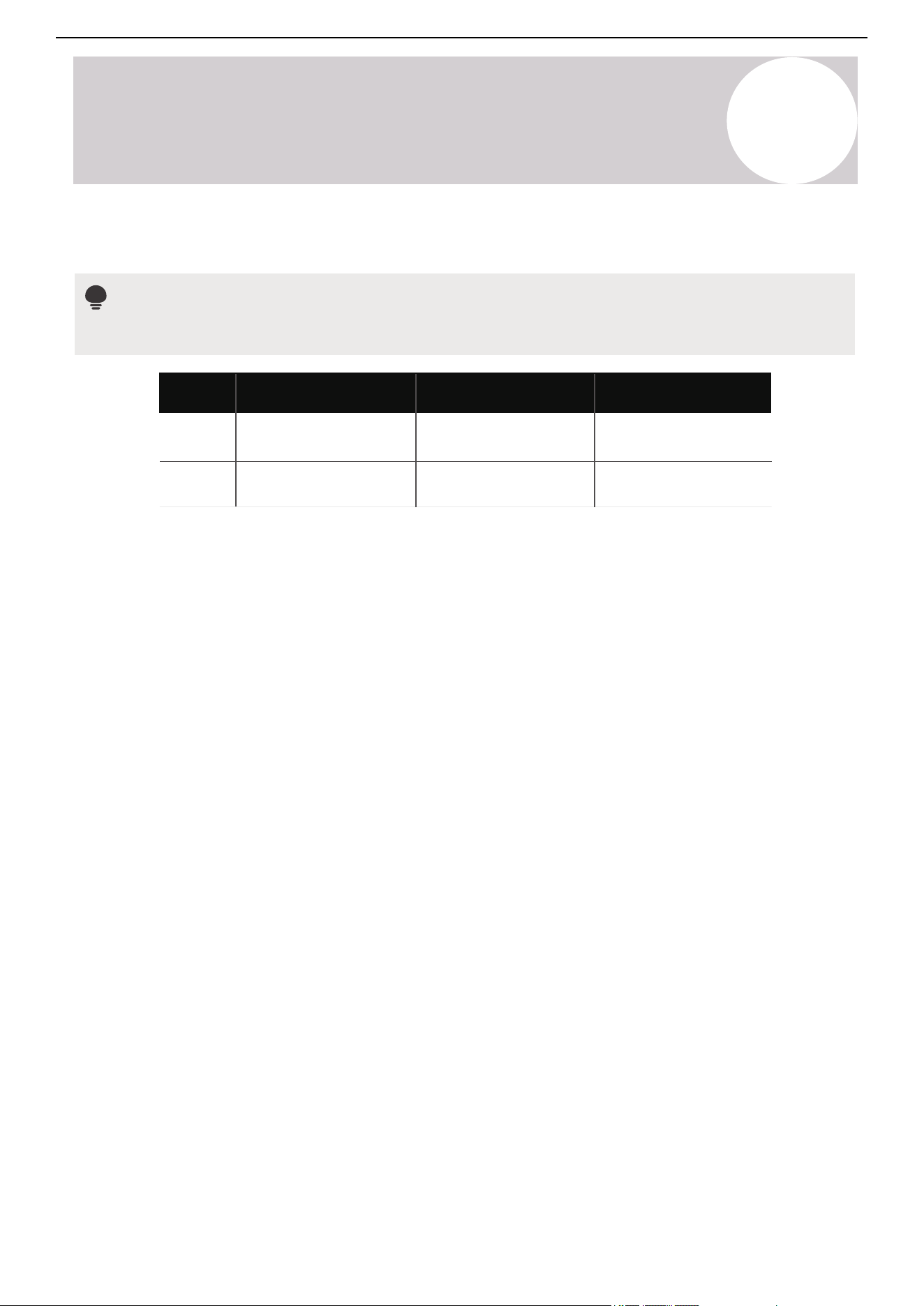
Model
Indoor Unit Outdoor Unit
36K CB036GMSILDFHG
48K CB048GMSILDFHG
YN036GMSI20RUG
YN048GMSI20RUG
Full System
CYB036GMSI20RL
CYB048GMSI20RL
Model Numbers
Note
Serial numbers are typically located behind the electronic control box cover cap of each unit.
16
Air Conditioner Installation & User Manual
Product Overview
2
2
3
6
7
8
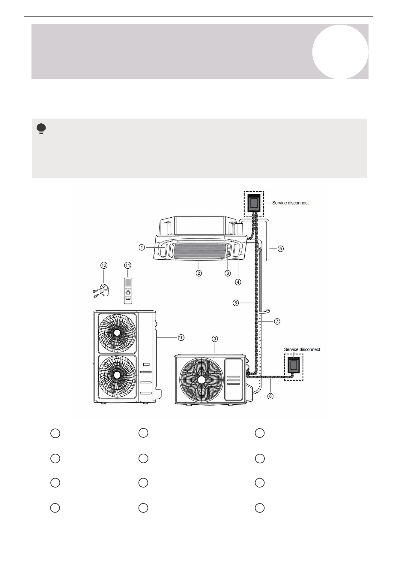
4 Display panel
Front grille
Air inlet
10
Communication cable
(purchase separately)
Refrigerant piping
(purchase separately)
Outdoor unit power cable
(purchase separately)
11
Outdoor unit (B)
Remote controller
Remote controller holder
(purchase separately)
12
1 5 9
Air outlet
Drain pipe
(purchase separately)
Outdoor unit (A)
Notes
• Illustrations in this manual are for explanatory purposes. The actual shape of the indoor unit may be
slightly different. The actual shape shall prevail.
• Select a service disconnect meeting the requirements of the local, regional, and national codes.
Part Names
17
Air Conditioner Installation & User Manual
Product Overview
2
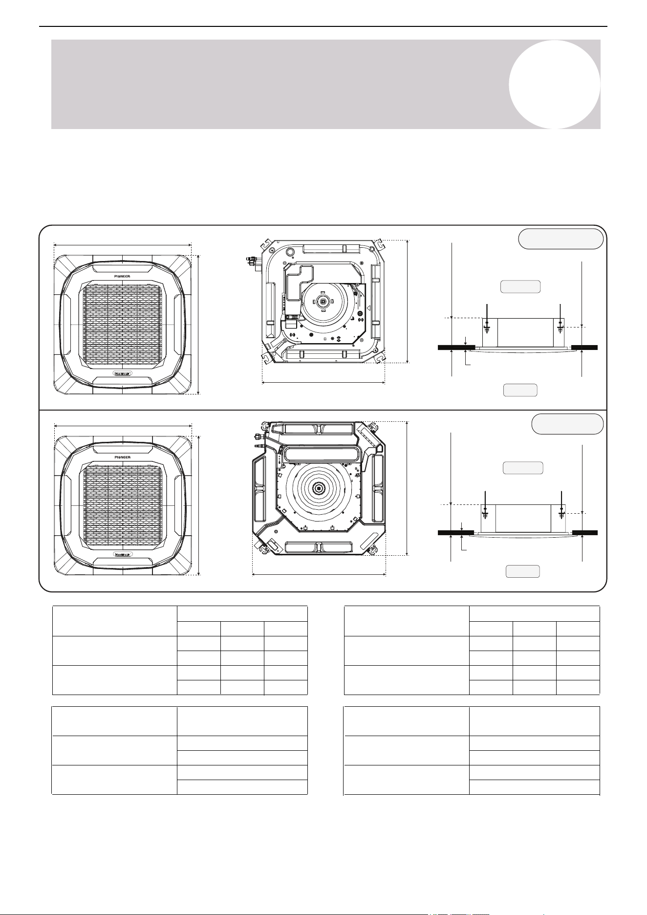
Ceiling
36K BTU
48K BTU
Ceiling
Floor
37-⅜ in (949 mm)
37-⅜ in (949 mm)
Panel thickness: 2-⅛ in (54 mm)
37-⅜ in (949 mm)
37-⅜ in (949 mm)
Panel thickness: 2-⅛ in (54 mm)
32-⅝ in (829 mm)
32-⅝ in (829 mm)
32-⅝ in (829 mm)
32-⅝ in (829 mm)
9-⅝ in (244 mm)
⅜ - 1 in (10-25 mm)
Floor
11-⅜ in (289 mm)
⅜ - 1 in (10-25 mm)
Dimensions & Weight
Indoor Unit:
W D H
Dimensions
Indoor Unit
CB036GMSILDFHG
CB048GMSILDFHG
32-5/8 in
32-5/8 in
9-5/8 in
32-5/8 in
32-5/8 in
11-3/8 in
829 mm
829 mm
244 mm
829 mm
289 mm
829 mm
W D H
Dimensions
Panel Grille
CB036GMSILDFHG
CB048GMSILDFHG
37-3/8 in
37-3/8 in 2-1/8 in
37-3/8 in
37-3/8 in 2-1/8 in
949 mm
949 mm 54 mm
949 mm 54 mm
949 mm
Net Unit Weight
Indoor Unit
CB036GMSILDFHG
CB048GMSILDFHG
59.3 lbs
64.5 lbs
26.9 kgs
29.3 kgs
Net Unit Weight
Panel Grille
CB036GMSILDFHG
CB048GMSILDFHG
13.2 lbs
6 kgs
6 kgs
13.2 lbs
18
Air Conditioner Installation & User Manual
Product Overview
2
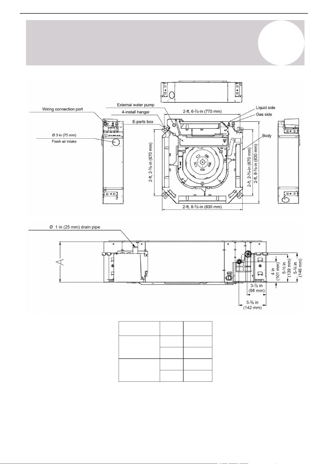
Model
(Btu/h)
Unit A
36K
mm
245
48K
inch
11-3/8
inch
9-5/8
mm
289
19
Front View
Top View
Air Conditioner Installation & User Manual
Product Overview
2
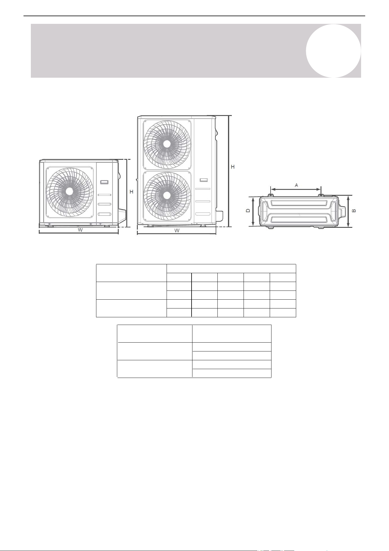
Outdoor Unit
W D H A B
Dimensions
Outdoor Unit
YN036GMSI20RUG
YN048GMSI20RUG
26-1/2 in
25 in
15-7/8 in
16 in
37-1/4 in
16-1/4 in 31-7/8 in
52-1/2 in
16-3/8 in
37-1/2 in
946 mm
952.5 mm
413 mm
416 mm
403 mm
406 mm
810 mm
1,333.5 mm
673 mm
635 mm
Net Unit Weight
Outdoor Unit
YN036GMSI20RUG
YN048GMSI20RUG
152.4 lbs
208.8 lbs
69.1 kgs
94.7 kgs
20
Air Conditioner Installation & User Manual
Product Overview
2
Testing and rating agencies develop standard rating conditions to obtain full system-rated capacity and
efficiency. Within certain limitations, variable speed compressors compensate the deviations from the rating
conditions, especially the atmospheric conditions.
Heat pump systems function by exchanging energy between the indoor air and outdoor ambient air
(atmospheric) in the form of heat. The system's net cooling or heating capacities and efficiencies change by
atmospheric conditions, as well as the indoor air conditions, such as temperatures and humidity levels.
Professional individuals use detailed calculations to determine the capacity of the system required for a
specific area or application, which are based on several internal and external factors.
To further optimize the performance of the unit, complete the following:
• Keep doors and windows closed.
• Use Timer On and Timer Off functions to limit energy usage.
• Do not block air inlets or outlets.
• Regularly inspect and clean air filters.
Operating Temperatures
The system is designed to run within a certain range of temperatures, which are listed below. The system has
built-in protections that may stop the appliance when the ambient temperatures goes outside of these ranges.
°F / °C
Operating
Temperatures
Temperature
Setting Range
62~86°F
Ambient Temperature
Range for Cooling
Ambient Temperature
Range for Heating
17~30°C
5~131°F
-15~55°C
-13~86°F
-25~30°C
21
Air Conditioner Installation & User Manual
Product Overview
2
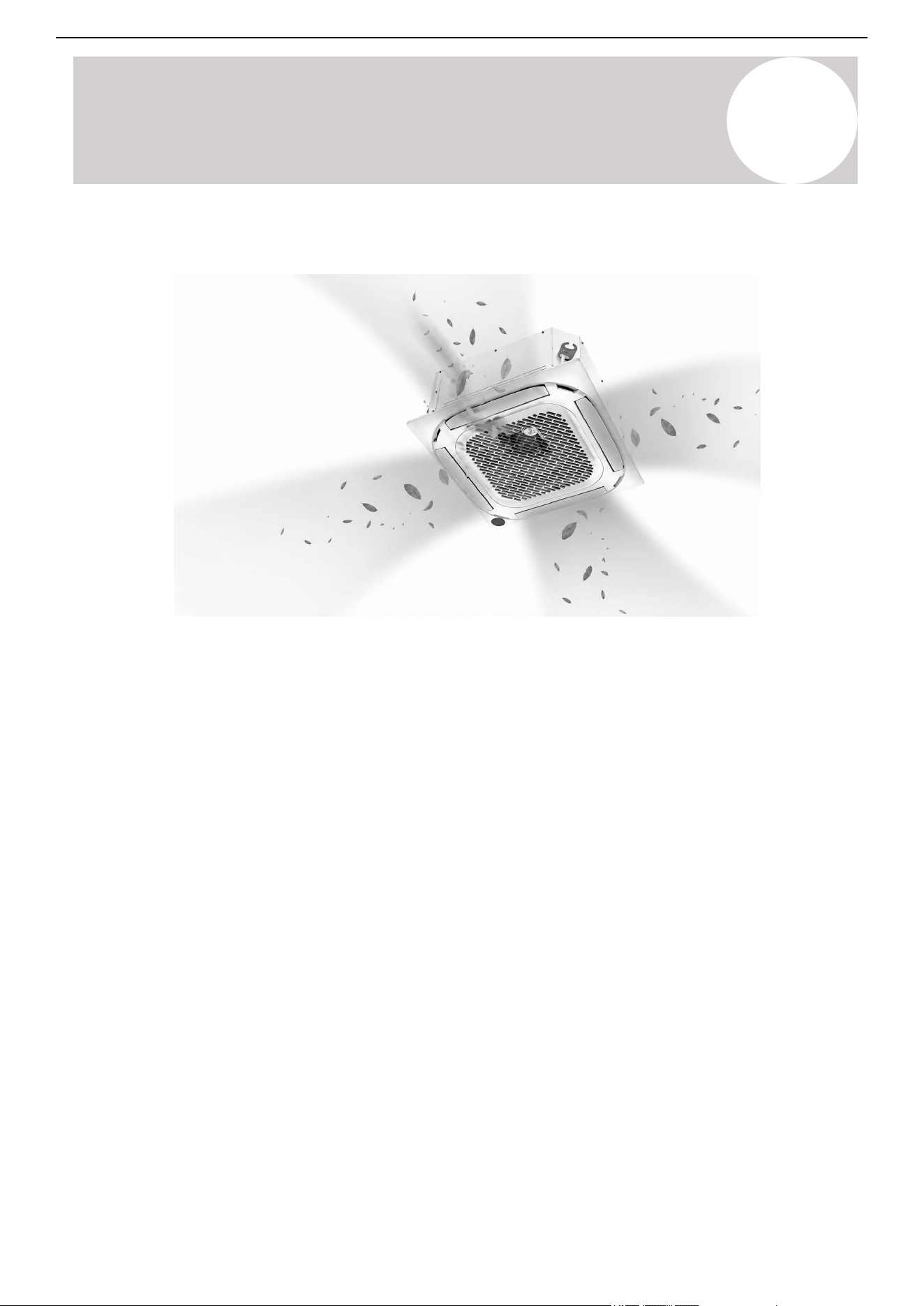
360-Degree Airflow
The 360-degree directional airflow delivers air evenly to every corner in any space, reducing hot and cold spots
in the room.
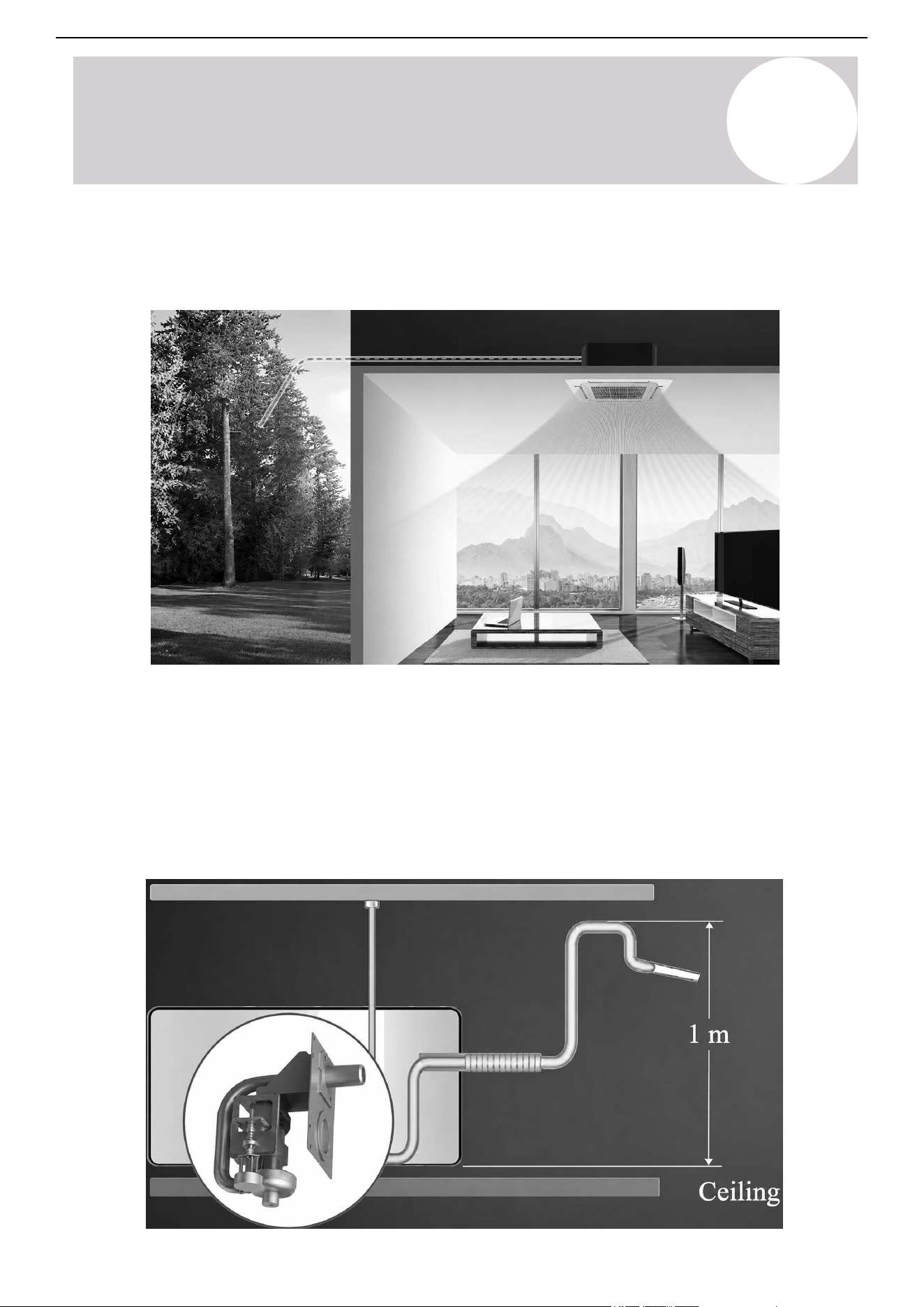
Easy Installation
The ceiling cassette is much slimmer due to the redesigned heat exchanger and overall structures. It now
requires less space for the installation.
Reserved Remote On-Off & Alarm Ports
Remote On-Off: A remote switch can be easily connected to the reserved ports, enabling the remote control
function.
Alarm: The built-in PCB can trigger an alarm signal to activate an external light or vibration gauge.
The ports are standard for inverter units, but not for fixed-speed units.
Features
22
Air Conditioner Installation & User Manual
Product Overview
2
Wired Controller (Optional)
Compared to infrared remote controllers, the wired controller can be mounted on the wall to prevent it from
being misplaced. It is primarily designed for commercial areas, making air conditioning control more convenient.
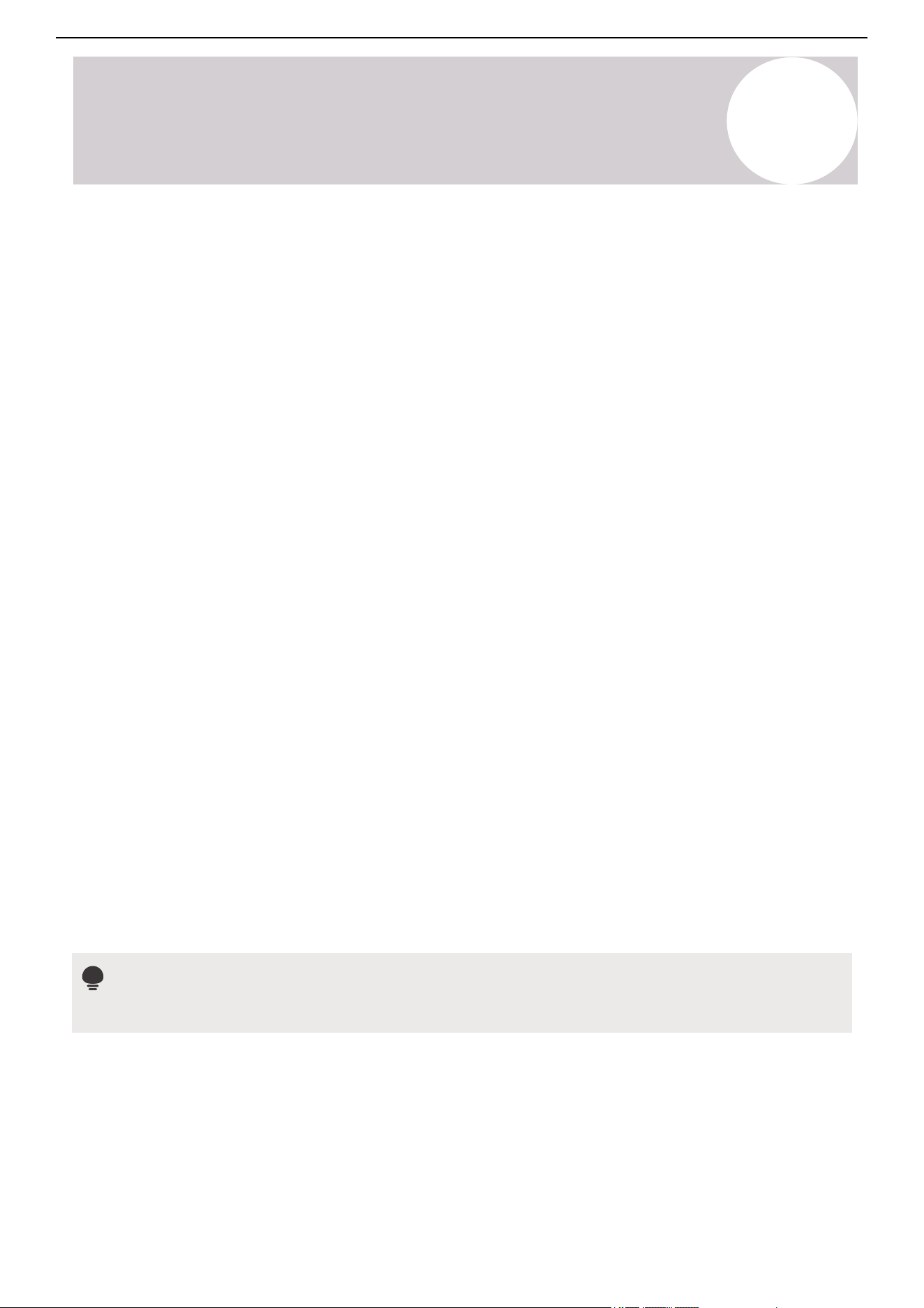
Built-in Drain Pump
The drain pump can lift the condensed water up to 3-feet, 3-⅜ inches (1 m). The condensate drain hose can be
installed on either the left or right side.
Fresh Air
The fresh air intake function provides a refreshing and comfortable experience.
23
Air Conditioner Installation & User Manual
Instructions for unpacking and packing the unit:
Unpacking:
Indoor Unit:
1. Cut the packing belt.
2. Unpack the package.
3. Take out the packing cushion and support.
4. Remove the packing film.
5. Take out the accessories.
6. Lift the machine out and lay it flat.
Outdoor Unit:
1. Cut the packing belt.
2. Take the unit out of the package.
3. Remove the foam from the unit.
4. Remove the packing film from the unit.
Packing:
Indoor Unit:
1. Put the indoor unit into the packing film.
2. Put the accessories in.
3. Place the packing cushion and support into the package.
4. Put the indoor unit into the package.
5. Close the package and seal it.
6. Use the packing belt if necessary.
Outdoor Unit:
Unpacking & Packing
3
1. Put the outdoor unit into the packing film.
2. Put the bottom foam into the box.
3. Put the outdoor unit into the package, then put the upper packaging foam on the unit.
4. Close the package and seal it.
5. Use the packing belt if necessary,
Note
Keep all the packaging items in case they're needed in the future.
24
Air Conditioner Installation & User Manual
Installation Overview
4
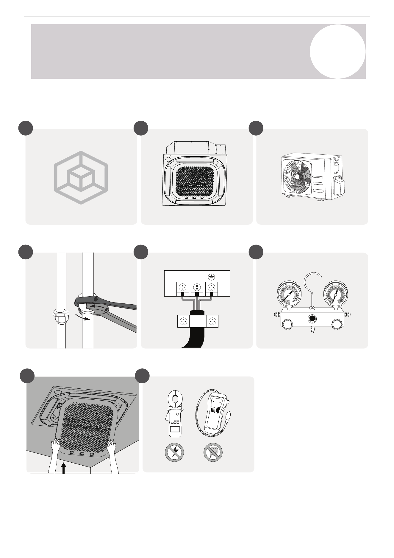
Installation Summary
Install the outdoor unit
Install the indoor unitSelect the installation locations
1 2 3
Evacuate the refrigeration system
Connect the wires
Connect the refrigerant pipes
4 5 6
Perform a test runInstall the panel
L1 L2
MC MC
7 8
25
Air Conditioner Installation & User Manual
3
6
6
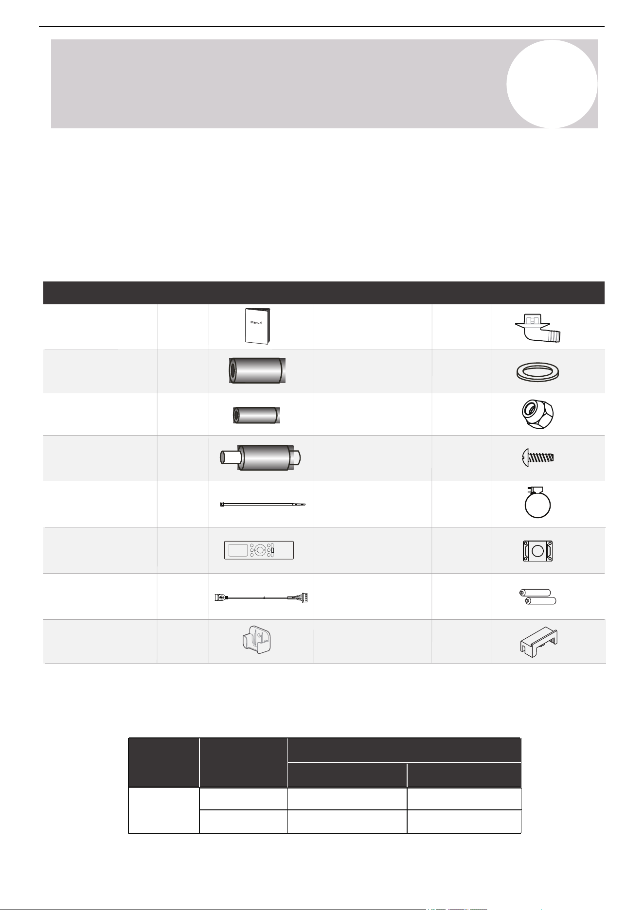
Manual
Soundproof/insulation
sheath (36K / 48K)
Outlet pipe sheath
(36K / 48K)
Drain joint
Throat bander
(36K/ 48K)
Belt
(36K / 48K)
Tapping screw
(36K/48K)
Conduit installation
plate
Remote controller
Battery
Wireless module cable
Rubber block
(36K/48K)
Remote controller holder
(purchase separately)
Name of Accessories
Name of Accessories
Qty Qty
Shape Shape
Soundproof/insulation
sheath (36K / 48K)
1
1
1
1
1
1
Copper nut
1
1
2
2
1
2
1
Installation Overview
4
Seal ring
Connecting Pipe Sizes
Pipes are not included in the accessories and need to be purchased separately from the local dealer.
Liquid Side Gas Side
Ø3/8 in (Ø9.52 mm)
36K
Ø3/4 in (Ø19 mm)
48K
Connecting
pipe
assembly
Name Model
Pipe Specification
Ø3/8 in (Ø9.52 mm) Ø3/4 in (Ø19 mm)
Accessories
The system comes with the following general accessories. Use all of the installation parts and accessories to
properly install the air conditioner. The included items may vary slightly depending on the model. Pioneer
reserves the right to modify the included components for product improvement without notice.
Improper installation may result in water leakage, electrical shock and fire, or equipment failure. The items that
are not included with the air conditioner must be purchased separately.
26

Air Conditioner Installation & User Manual
Installation Overview
4
Optional Accessories
There are two types of remote controls: Wired and wireless.
Select a remote controller based on customer preferences and requirements. Install the remote control in an
appropriate place. Refer to catalouges and technical literature for guidance on selecting a suitable remote
controller.
27
Air Conditioner Installation & User Manual
Installation
5
Select the Installation Locations
5.1.
Notes
• Before starting, refer to the label on the product box to make sure that the model number of the indoor
unit matches the model number of the outdoor unit.
• We recommend understanding the guidelines for selecting ideal locations for the indoor and outdoor units.
• Refrain from exerting force on other parts of the unit, especially the refrigerant piping, water discharge
piping, and plastic parts.
Before installing the indoor and outdoor units, choose the appropriate locations.
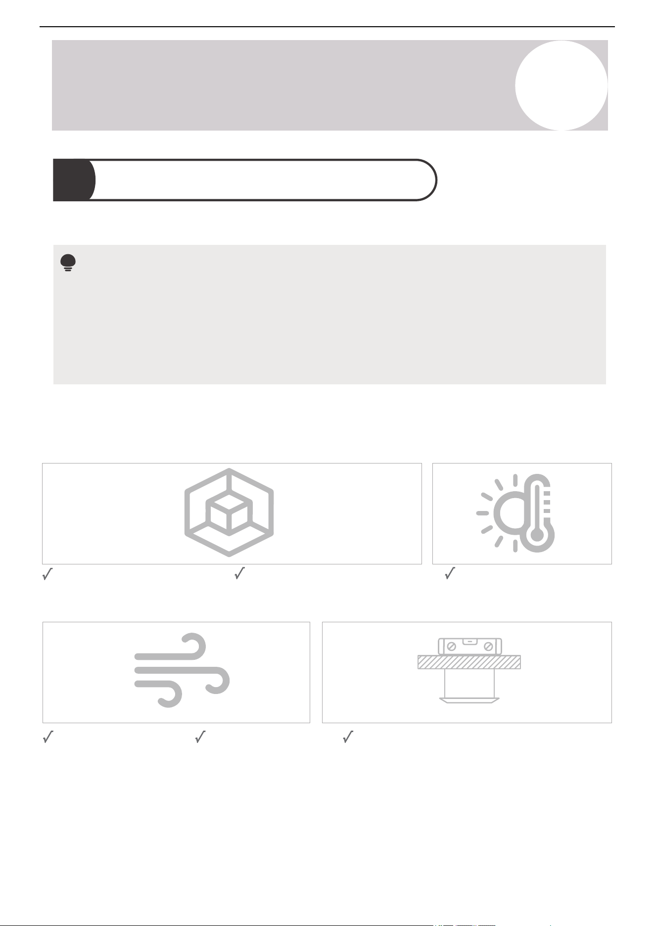
Sufficient space for installation
and maintenance.
Sufficient space to connect the
refrigerant pipes and condensate
drain hose.
The ceiling is horizontal and its structure can
sustain the weight of the indoor unit.
The air inlet and outlet
are not blocked.
The airflow can fill the
entire room.
No direct radiation from
heaters.
Indoor Unit
Select an indoor unit installation location that meets these standards:
28
Air Conditioner Installation & User Manual
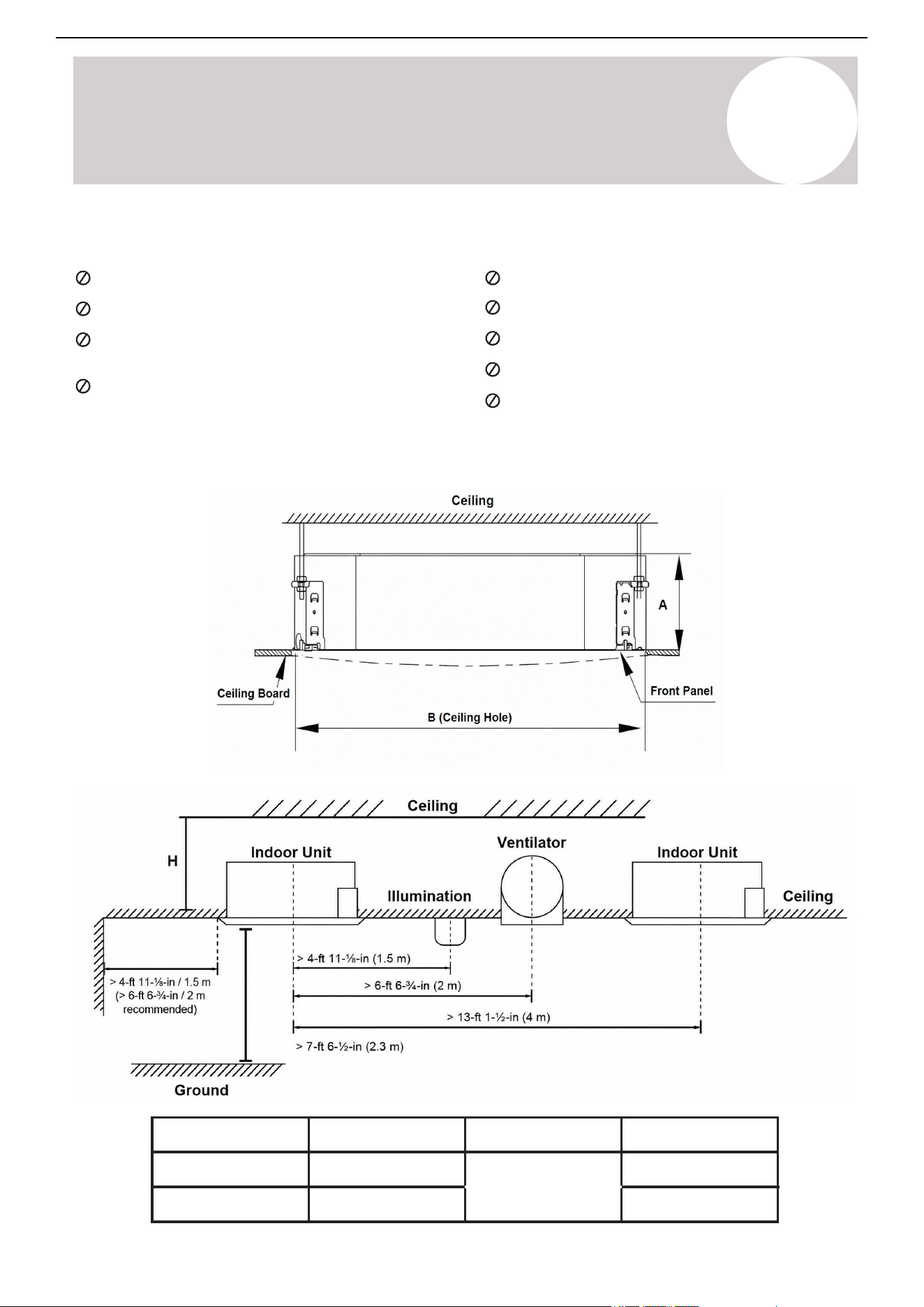
The distance between the indoor unit and internal ceiling must meet the following specifications:
Capacity (BTU/h)
A (inch/mm)
H (inch/mm)
B (inch/mm)
2-ft, 11-⅜-in (35-⅜)
/ 900
36K
9-⅝ / 245
> 10-¾ / 271
48K
11-¼ / 287
> 12-¼ / 313
Installation
5
Areas with oil drilling or fracking.
Coastal areas with high salt content in the air.
Areas with caustic gases in the air, such as hot
springs.
Areas that experience power fluctuations, such
as factories.
Enclosed spaces, such as cabinets.
Kitchens that use natural gas.
Areas with strong electromagnetic waves.
Areas that store flammable materials or gas.
Rooms with high humidity, such as bathrooms or
laundry rooms.
Do not install the indoor unit in the following locations:
29
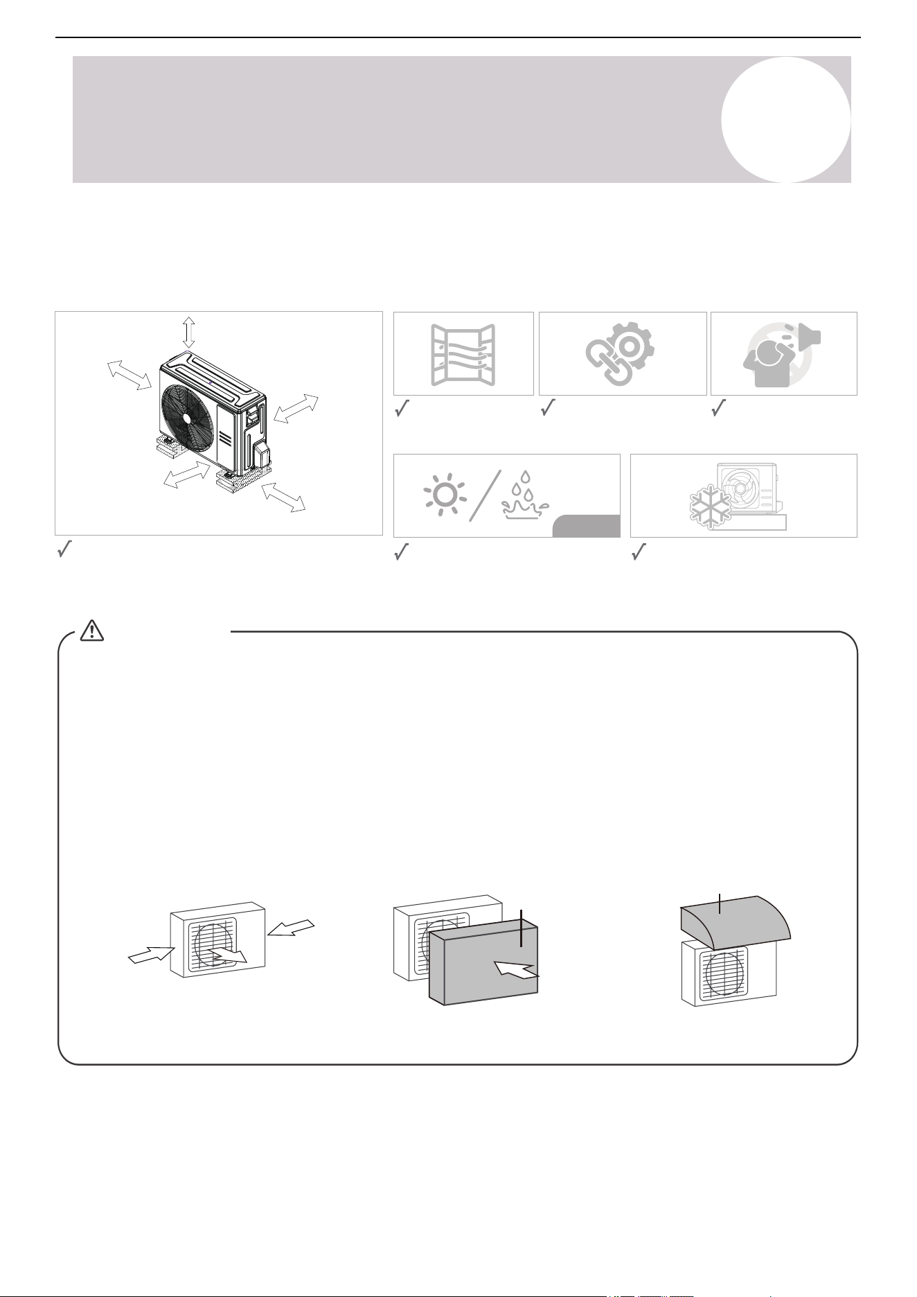
Air Conditioner Installation & User Manual
Firm and solid—the
location can support the
unit and will not vibrate.
Protected from prolonged periods of
direct sunlight or rain.
Where snowfall is anticipated, take
appropriate measures to prevent ice
buildup and coil damage.
Good air circulation
and ventilation.
Noise from the unit will
not disturb other
people.
Long-term
Meets all spatial requirements shown in the
installation clearance requirements above.
20 in (500mm) or more when front and
sides of the unit are clear
20 in (500 mm) or more
when any 2 sides of left,
right, and rear of the
unit are clear.
14 in (350 mm)
or more
4 in (100 mm)
or more
4 in (100 mm)
or more
Strong
wind
Strong
wind
Strong
wind
Wind Baffle
90-degree angle to the
direction of the wind
Build a wind baffle to
protect the unit
Build a shelter to protect
the unit
CAUTION:
Shelter
Special Considerations for Extreme Weather
If the unit is exposed to heavy wind:
Install the unit so that the air outlet fan is at a 90-degree angle to the wind direction. If necessary, build a barrier
in front of the unit to protect it from extremely strong winds.
If the unit is frequently exposed to heavy rain or snow:
Build a shelter above the unit to protect it from rain or snow, ensuring the airflow is not obstructed.
If the unit is frequently exposed to salty air (seaside):
Use an outdoor unit specifically designed for corrosion resistance.
Installation
5
Outdoor Unit
Select an outdoor unit installation location that meets these standards:
30
Air Conditioner Installation & User Manual
Do not the install the outdoor unit in the following locations:
Installation
5
Near an obstacle that will block
air inlets and outlets.
Near public streets, crowded
areas, or places where noise
from the unit will disturb others.
Near animals or plants
that will be harmed by
hot air discharge.
Near any source of
combustible gas.
A location that is exposed to
large amounts of dust.
A location exposed to an
excessive amount of salty air.
31
Air Conditioner Installation & User Manual
Installation
5
CAUTION
The unit's body should align perfectly with the
hole. Ensure the unit and hole are the same size
before proceeding.
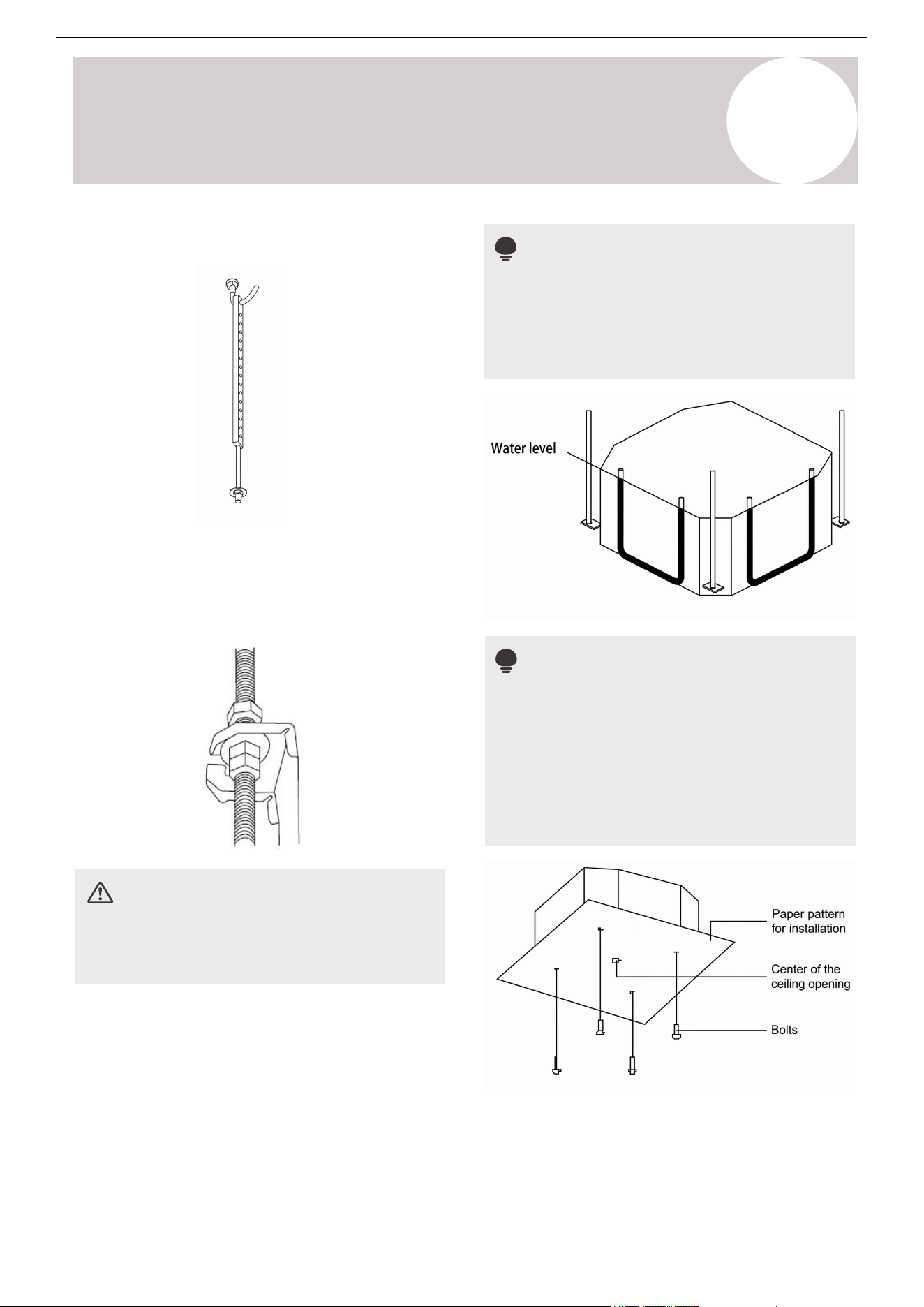
2. Drill four holes, between 4-¾ ~ 6-⅛ inches
(120~155 mm) deep, at the marked ceiling hook
positions in the internal ceiling. Be sure to hold the
drill at a 90-degree angle to the ceiling.
3. Use a hammer to insert the ceiling hooks into the
pre-drilled holes. Secure the bolt using the included
washers and nuts.
Indoor Unit Installation
5.2.
A. Hang the Indoor Unit
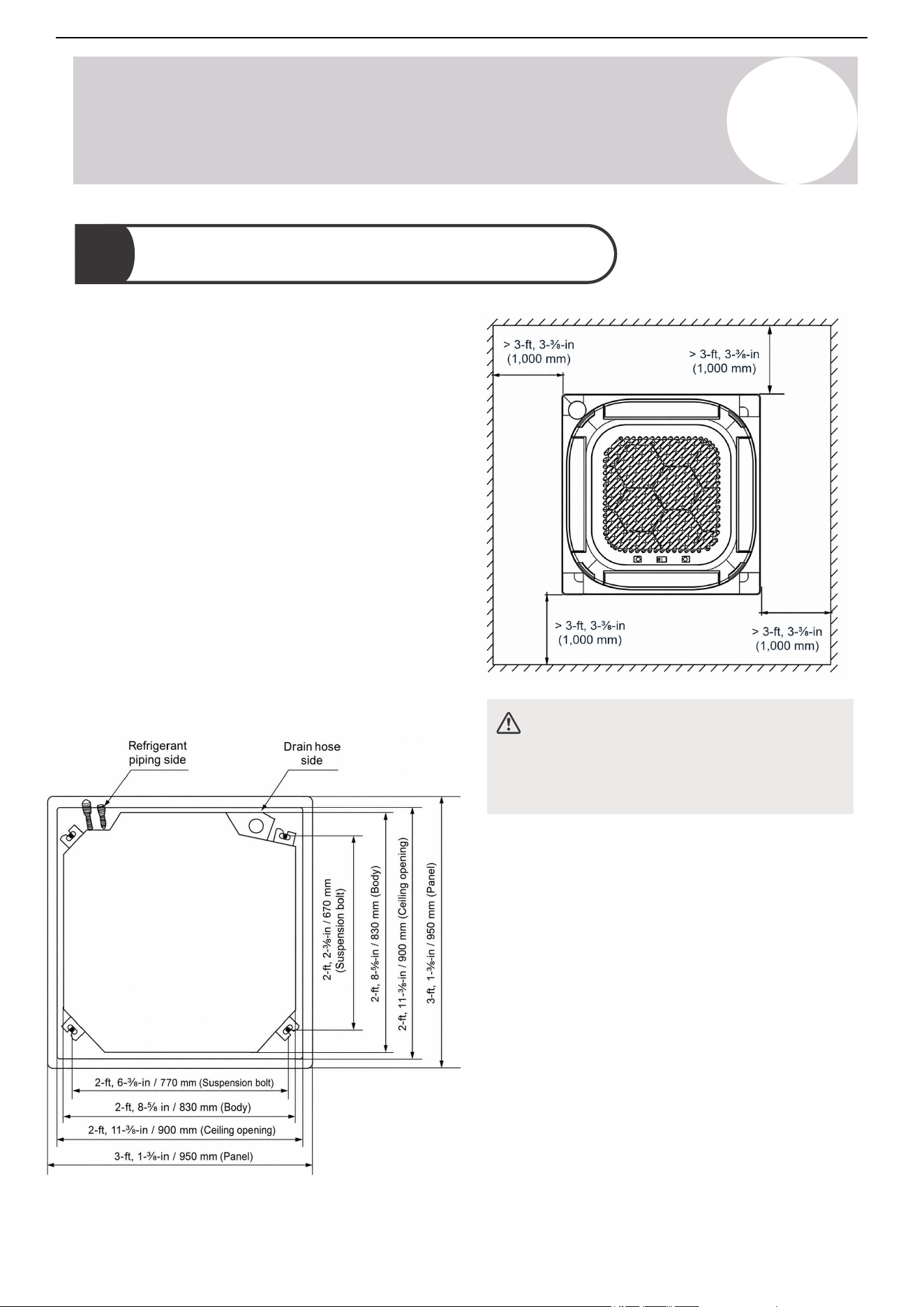
1. Use the included paper template to cut a
rectangular hole in the ceiling, leaving at least 3-feet,
3-⅜-inches (1 m) on all sides. The cut hole size
should be 16 inches (406 mm) larger than the body
size.
Be sure to mark the positions where the ceiling hook
holes will be drilled.
Refer to the illustrations below.
32
Air Conditioner Installation & User Manual
Installation
5
4. Install the four suspension bolts.
5. Mount the indoor unit. This process will require
two people to lift and secure the indoor unit. Insert
the suspension bolts into the unit's hanging holes.
Fasten them using the included washers and nuts.
Note
The unit is equipped with a built-in drain pump
and float switch. If the unit is tilted against the
direction of the condensate flow (the drain line
side is raised), the float switch may
malfunction and cause water leakage.
Note for New Home Installation
When installing the unit in a new home, the ceiling
hooks can be embedded in advance. Make sure
the hooks do not come loose due to concrete
shrinkage. After installing the unit, fasten the
installation paper template onto the unit with bolts
to determine the dimensions and position of the
ceiling opening. Follow the instructions above for
the remainder of the installation.
CAUTION
Ensure the unit is completely level. Improper
installation can cause the drainpipe to back up
into the unit or water leakage.
33
Air Conditioner Installation & User Manual
Installation
5
Note
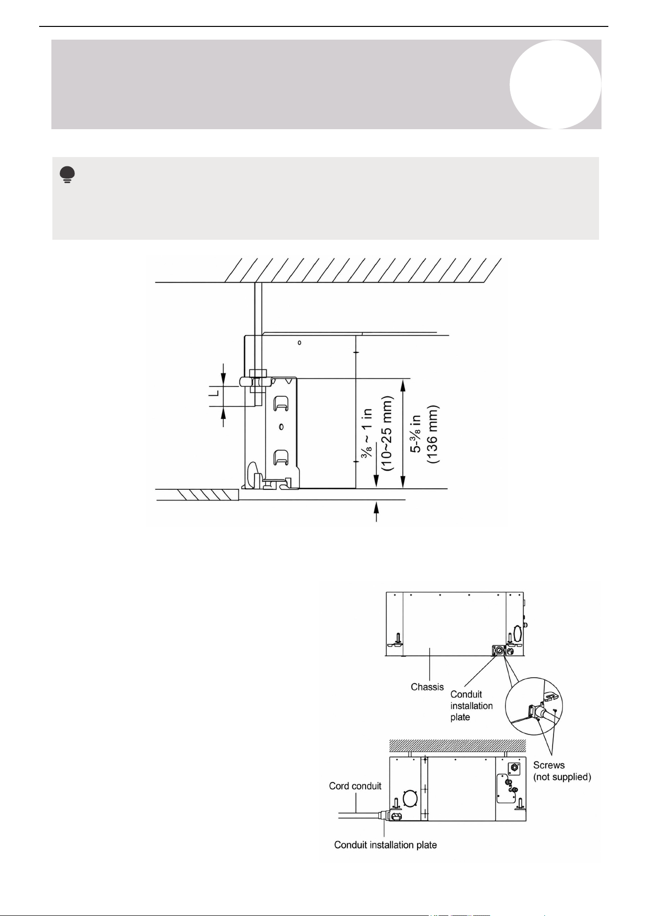
The bottom of the unit should be ⅜ of an inch to 1 inch (10-25 mm) higher than the ceiling board. Generally,
"L" (indicated in the following figure) should be half the length of the suspension bolt or long enough to
prevent the nuts from coming off.
B. Install the Conduit Installation Plate (If Supplied)
1. Attach the sheath connection (not supplied) to the
wire hole of the conduit installation plate.
2. Attach the conduit installation plate to the unit's
chassis.
34
Air Conditioner Installation & User Manual
Installation
5
1. Determine the wall hole's location based on the intended position of the outdoor unit.
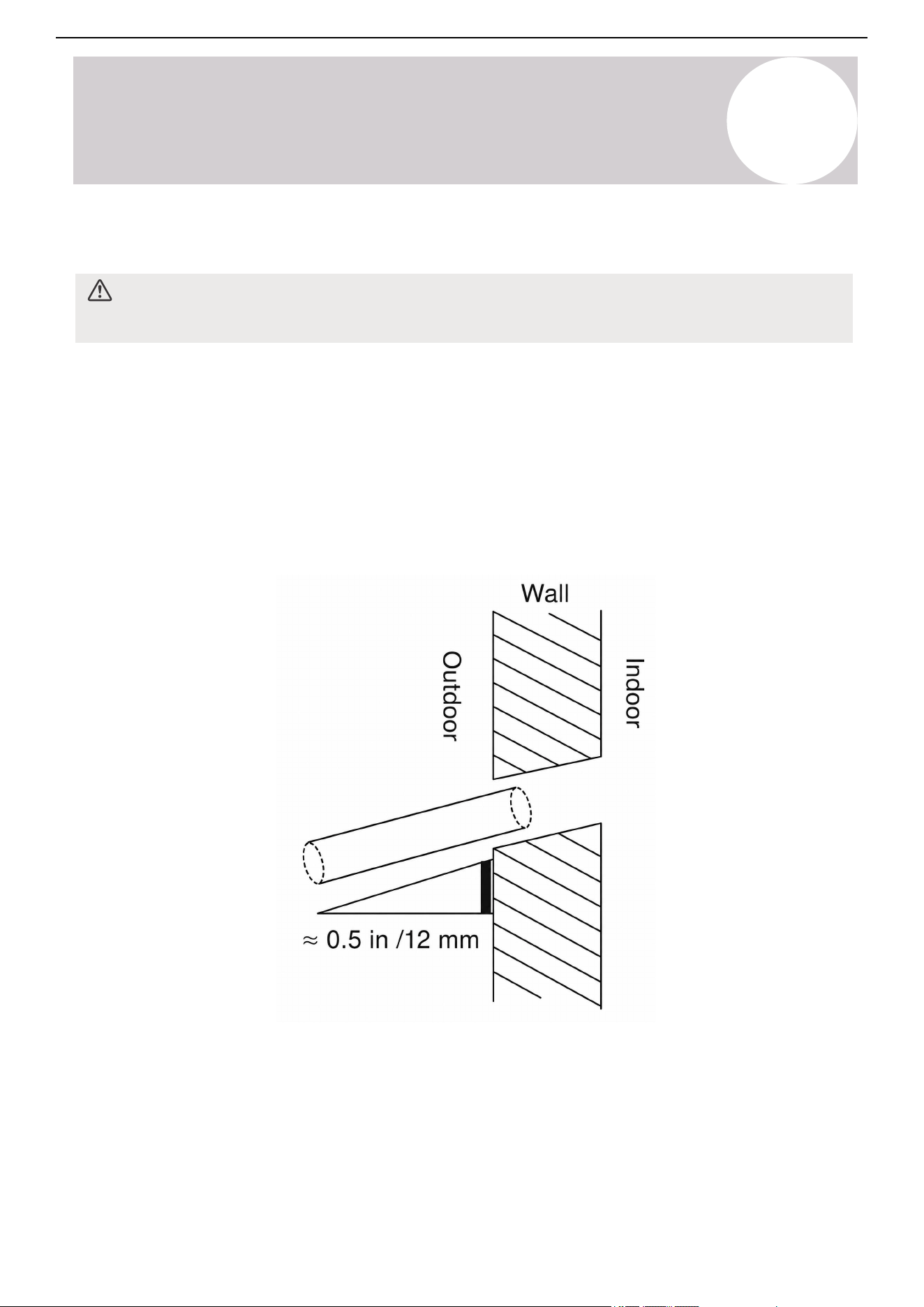
2. Drill a hole through the wall using a 3-½ inches (90 mm) core drill. Make sure the hole is angled slightly
downward so that the exterior opening is a ½ inch (12 mm) lower than the interior opening. This slope ensures
proper water drainage.
3. Insert the protective wall cuff into the hole. This protects the edges of the hole and helps create a seal during
the final installation steps.
C. Drill the Wall Hole for the Piping
When drilling the wall hole, make sure to avoid wires, plumbing, and other sensitive components.
CAUTION
The hole being drilled in the wall is intended for the drainage and refrigerant piping.
35
Air Conditioner Installation & User Manual
Installation
5
D. Install the Condensate Drain Hose
The condensate drain hose, also called a drain line, directs water away from the unit. Improper installation may
cause property damage.
Notes
• When using an extended drain line, tighten the indoor connection with an additional protection tube to
prevent accidental disconnection.
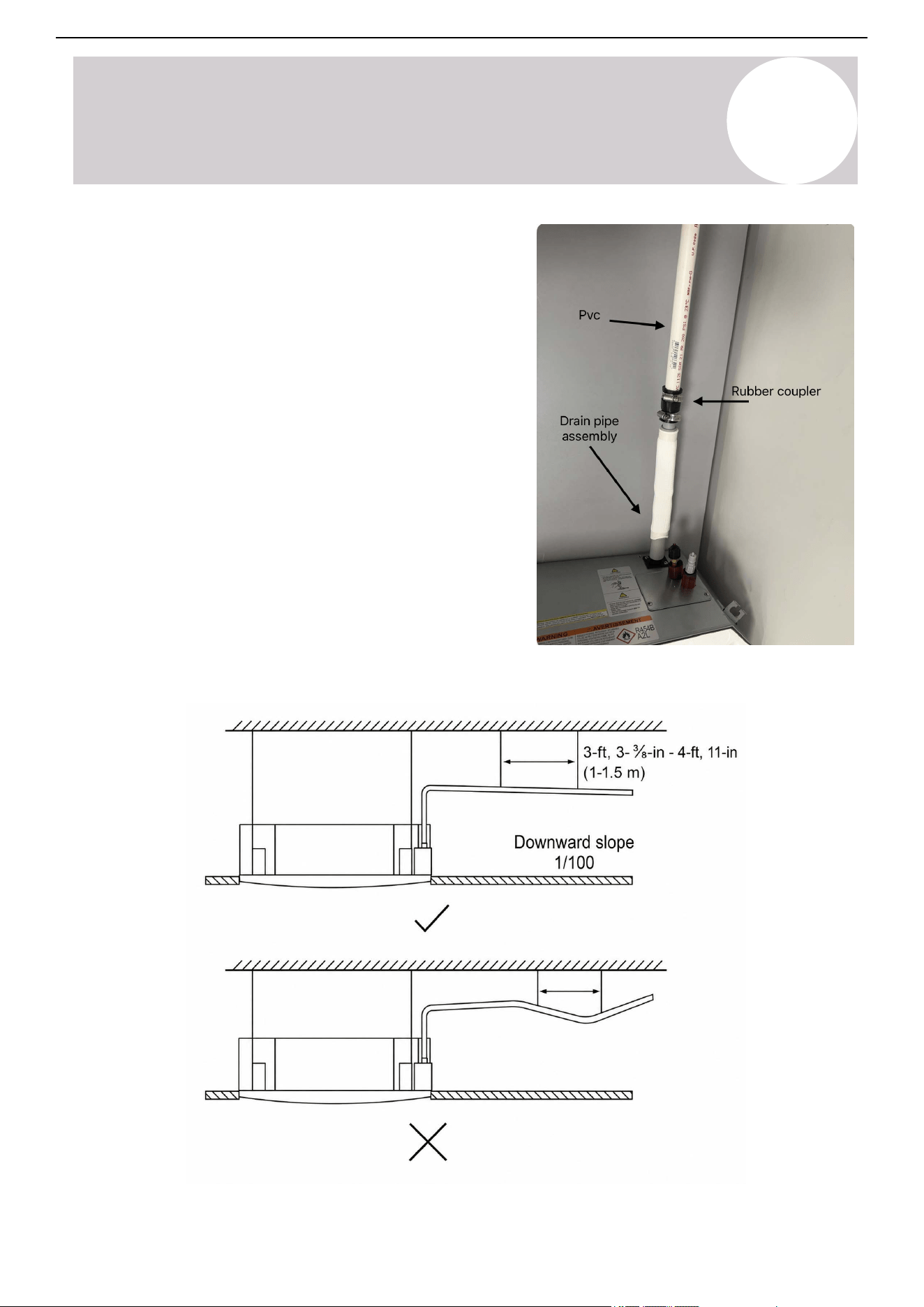
• The drain line should slope downward at a gradient of at least 1/100 to prevent water from flowing back
into the air conditioner.
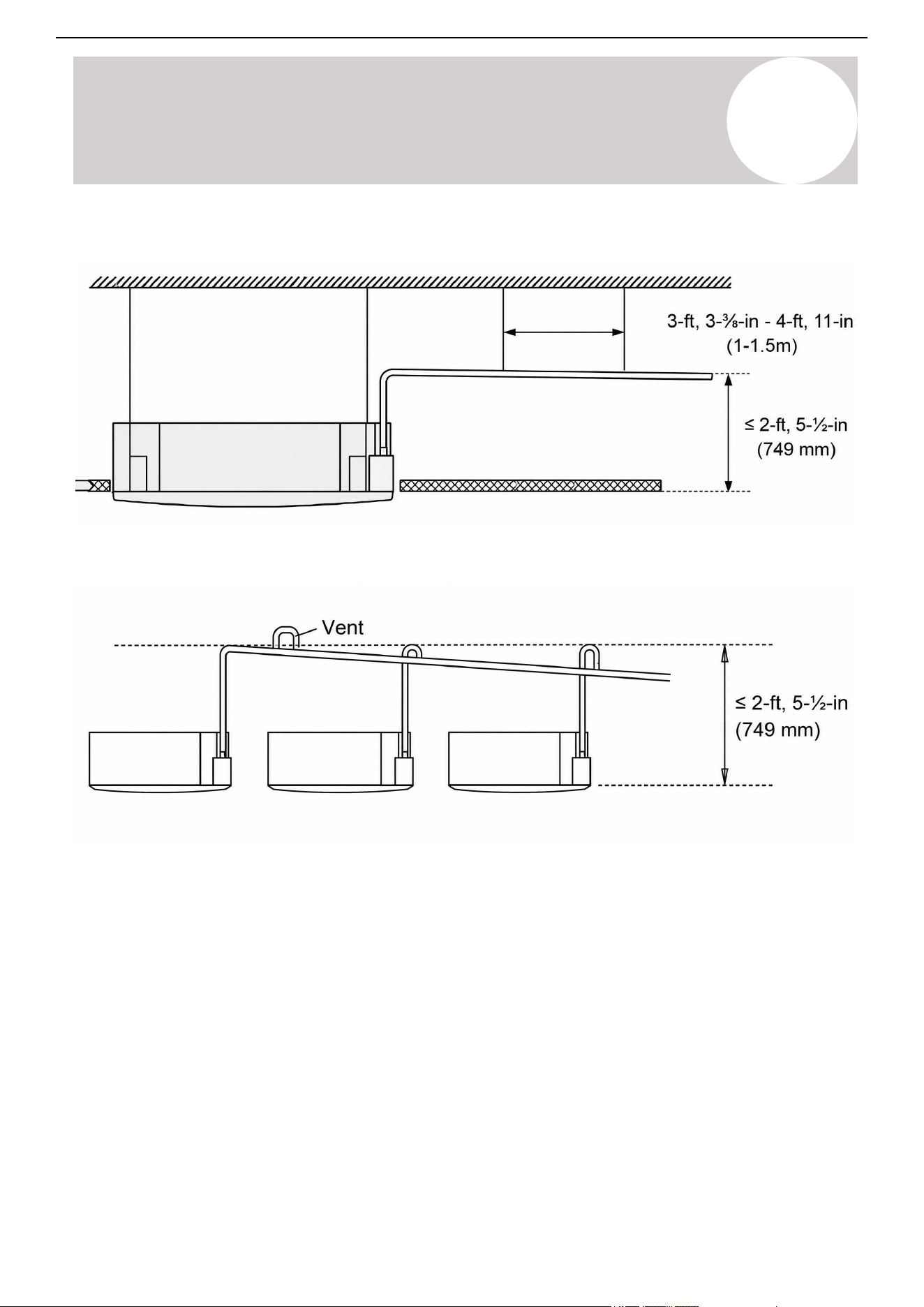
• If the drain line outlet is higher than the pump joint, install a lift pipe for the indoor unit's exhaust outlet. Do
not install the lift pipe higher than 2-feet, 5-½-inches (750 mm) from the ceiling board. The distance
between the unit and lift pipe must be less than 11-¾ inches (300 mm). Improper installation may result in
water backflow, potentially flooding the unit.
• To prevent air bubbles, keep the drain line level or slightly tilted up by 3 inches (less than 75 mm).
• Installation requires a polyethylene tube (exterior diameter = 1 in / 25 mm), which can be obtained at a
local hardware store or dealer.
CAUTION
• Ensure the drain line installation complies with all local and national codes and regulations.
• Verify that the drain line is insulated to prevent condensation and potential water damage. If it is not,
insulate it properly.
• If the drain line is bent or installed incorrectly, water may leak and cause a water-level switch malfunction.
• Do not pull the drain line forcefully. This could disconnect it.
36

Air Conditioner Installation & User Manual
Installation
5
1. Plan the Drain Line Layout
Before beginning the installation, plan the drain line layout and connection.
2. Cut the Drain Line (If Needed)
If necessary, cut the drain line to fit your layout and connection.
3. Insulate the Drain Line (If Needed)
Verify that the drain line is insulated to prevent condensation and potential water damage. If it is not, insulate it
properly. Insufficient insulation may allow dew to form due to low condensate temperatures, resulting in potential
water damage.
Insulate the drain line before beginning the connection, excluding the joint sections. These will be insulated at
the end of the procedure.
Ensure the insulation material is fitted tightly with no gaps. Do not over-tighten the insulation material. This may
compress the air out of the material, causing poor insulation and early aging.
The insulation material must be made of flame-retardant material. Select a material that complies with local
regulations.
The thickness of the insulation material must be more than ⅜ of an inch (10 mm).
Apply specialized adhesive to the insulation seams, then secure them with tape. Ensure the tape is at least 2
inches (51 mm) wide and applied firmly to prevent condensation.
4. Connect the Drain Hose
Attach the drain hose to the indoor unit's drain line connection.
Unlike wall-mounted systems, ceiling cassette units and other light commercial air conditioning systems require
a PVC drain line. The flexible drain hoses are not suitable for these applications.
Use a rubber coupler to connect the drain hose to the PVC drain line, ensuring a secure, water-tight seal. The
rubber coupler and PVC drain line are sold separately from the system.
37
Air Conditioner Installation & User Manual
Installation
5
Install the drain line assembly as illustrated:
This is how the drain line assembly should look when
attached to the PVC line with the rubber coupler:
38
Air Conditioner Installation & User Manual
Installation
5
When connecting multiple drain hoses, install them as illustrated:
39

Air Conditioner Installation & User Manual
Installation
5
5. Pass the Drain Line Through the Wall Hole
When passing the drain line through the wall hole, make sure the water drains to a safe location where it will
not cause water damage or a slipping hazard.
The drain line outlet should be at least 1-⅞ inches (50 mm) above the ground. If it touches the ground, the unit
may become blocked, potentially leading to a malfunction.
If the water is discharged directly into the sewer, ensure the drain has a U or S pipe to prevent odors from
coming back into the house.
6. Complete a Drainage Test
Ensure the condensate drains to a suitable location by completing the drainage test. New buildings should
perform this test before finishing the ceiling.
a. Remove the test cover.
b. Add 68 ounces (2,000 ml) of water to the tank through the attached tube.
c. Turn on the main power switch and run the appliance in Cooling mode.
d. Listen for any unusual noises coming from the drain pump.
e. Confirm the water is discharging to the proper location. It may take up to a minute for the unit to begin
draining, depending on the drain line.
f. Ensure there are no leaks in the drain line.
g. Stop the appliance. Turn off the main power switch and reinstall the test cover.
7. Insulate the Joint Sections
The pipe joint insulation should be 2~4 inches (51~102 mm) longer than the gap to ensure a proper seal.
Insert the pipe joint insulation into the gap of the existing insulation.
Ensure the pipe joint insulation is securely fastened to the suction and liquid pipes to prevent gaps. Use glue to
paste together the linking part. Do not over-tighten the insulation material. This may compress the air out of the
material, causing poor insulation and early aging.
40
Air Conditioner Installation & User Manual
Installation
5
5.3.
Outdoor Unit Installation
A. Install the Drain Joint (Optional)
The outdoor condensate drain hose is optional. It is only needed if the user does not want to use the default
bottom drainage port.
If a drain hose is required, install the drain joint in the base pan hole of the outdoor unit before mounting. When
mounting the outdoor unit on slabs, the installation of the drain joint and hose is not necessary.
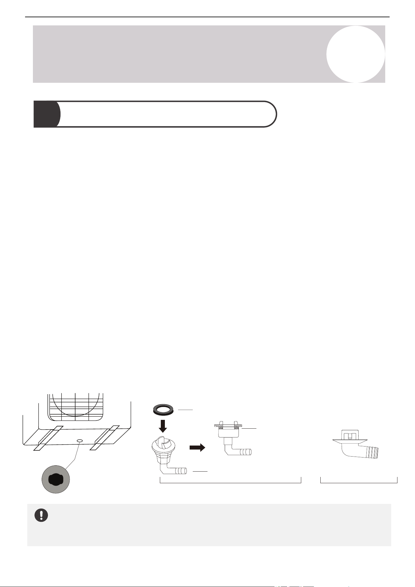
There are two types of drain joints for the outdoor unit: one with a rubber seal and one without.
If the drain joint comes with a rubber seal (Figure A), follow these steps:
In Cold Climates
In cold climates, make sure the drain line is as vertical as possible to ensure swift water drainage. If water drains
too slowly, it can freeze in the hose and flood into the unit.
Base pan hole of
the outdoor unit
Seal
Seal
Drain joint
(A) (B)
1. Fit the rubber seal on the end of the drain joint connecting to the outdoor unit.
2. Insert the drain joint into the hole of the unit's base pan.
3. Rotate the drain joint 90-degrees until it clicks into place facing the front of the unit.
4. Connect a drain hose extension (not included) to the drain joint in order to redirect water from the unit during
Heating mode.
If the drain joint does not come with a rubber seal (Figure B), follow these steps:
1. Insert the drain joint into the base pan hole, then press firmly to ensure it is properly installed and does not
become loose.
2. Connect a drain hose extension (not included) to the drain joint in order to redirect water from the unit during
Heating mode.
41
Air Conditioner Installation & User Manual
Installation
5
B. Mount the Outdoor Unit
WARNING
When drilling into concrete, eye protection is recommended at all time.
• Before connecting any pipes or cables, install the outdoor unit on a pad or solid wall using suitable
mounting brackets.
• Decide the best position on the wall or ground and leave enough space in order to carry out maintenance
easily.
• Follow all national regulations when installing the unit.
Mounting on Slabs
• The installation of the drain joint and tubing is not necessary when mounting the unit on slabs.
Wall Mounting
• Before mounting the unit on the wall, make sure the wall is made of solid brick, concrete, or a similarly
strong material. The wall must be able to support at least four times the weight of the unit.
• Fasten the supporting brackets to the wall using hardware that is particularly suited for the type of wall.
Use the appropriate amount of hardware for the application. Installing four rubber pads is optional.
• If allowed, install the wall-mounted unit with rubber gaskets to reduce vibration and noise.
Before mounting the outdoor unit, read these notes:
General Notes
Notes
Choose the best location on the wall or ground, leaving enough space for easy maintenance. The outdoor unit
can be mounted to the ground or on wall brackets. The following list shows different outdoor unit sizes and the
distance between their mounting feet. Prepare the installation base for each unit according to the dimensions
found on Page 20 in the Product Overview section.
42

Air Conditioner Installation & User Manual
Installation
5
1. Mark the positions for the four bolts based on the dimensions.
2. Pre-drill holes for the bolts.
3. Clean the concrete dust away from the holes.
4. Place a nut on the end of each bolt.
5. Hammer the bolts into each hole.
6. Remove the nuts from the bolts and place the outdoor unit onto the bolts.
7. Put washers onto each expansion bolt, then replace each of the nuts.
8. Use a wrench to tighten each nut until snug.
Ground/Concrete Mounting Platform
1. Mark the positions for the bracket holes based on the dimensions.
2. Pre-drill holes for the bolts.
3. Clean the concrete dust away from the holes.
4. Place a washer and nut on the end of each bolt.
5. Thread expansion bolts through the holes in the mounting bracket. Then, put the mounting bracket in position
and hammer the expansion bolts into the wall.
6. Confirm the mounting bracket is level.
7. If the feet of the outdoor unit have rubber pads already installed and are using a local dealer's wall-mounting
bracket, remove them before attempting to mount the condenser to the bracket. The mounting bracket has
rubber isolating pads on it that will take the place of these.
8. Carefully lift the unit and place its mounting feet on the brackets.
9. Bolt the unit firmly to the brackets.
Wall-Mounted Bracket
43
Air Conditioner Installation & User Manual
Installation
5
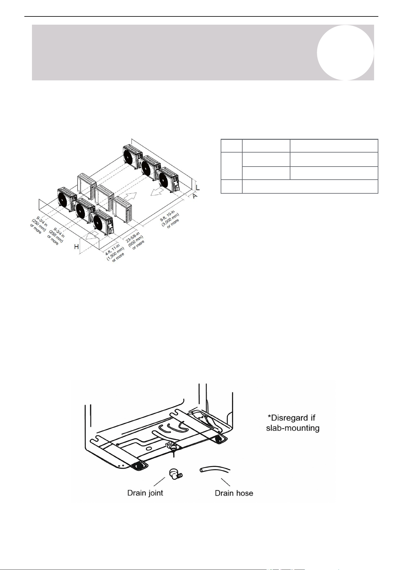
L ≤ H
L ≤ 1/2H
L A
9-¾ in (250 mm) or more
1/2H < L ≤ H
11-¾ in (300 mm) or more
L > H
Cannot be installed
H: Unit height
L: Height of the wall behind the unit
A: Distance between the unit and wall
Multiple Outdoor Units
If multiple outdoor units are being installed in a row, follow these guidelines:
C.
Install the Condensate Drain Hose (Optional)
The outdoor condensate drain hose is optional. It is only needed if the user does not want to use the default
bottom drainage port. Installing a drain hose is unnecessary if the unit is slab-mounted.
Instructions for planning the drain line layout, cutting the hose, and adding insulation are on Page 36 in the
Installation section. Revisit this page if necessary.
1. Connect the condensate drain hose to the drain joint at the bottom of the unit.
2. Ensure the water drains to a suitable location.
44
Air Conditioner Installation & User Manual
Installation
5
5.4.
Refrigerant Piping Connection
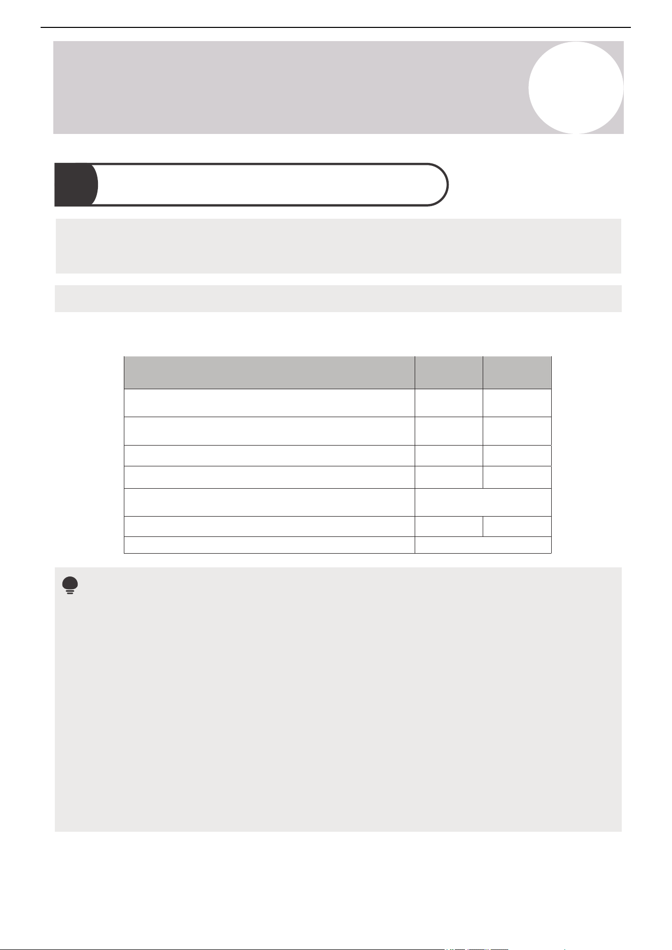
Prerequisite:
• Do not connect the refrigerant piping until both the indoor and outdoor units have been installed.
Liquid Pipe Diameter
Gas Pipe Diameter
Max. Length of Pipe with Standard Charge
Max. Length Between Indoor and Outdoor Unit
Adjustment Refrigerant Charge
(For each additional foot after 25 ft.)
Max.
Drop Height
Between Indoor and Outdoor Unit
CYB-20
Type of Refrigerant
36
K BTU 48
K BTU
Φ
3/
4
in
25 ft / 7.6 m 25 ft / 7.6 m
250 ft / 76 m
100 ft / 30.5
m 100
ft / 30.5 m
250 ft / 76 m
R-
454B
0.
32
oz/ft
Φ 3/8 in
Refer to this table for refrigerant piping specifications, such as maximum length and drop height.
Refrigerant Piping Specifications
Φ
3/
4
in
Φ 3/8 in
Notes
• Confirm the refrigerant piping is insulated. All refrigerant piping from Pioneer arrives pre-insulated. If you
purchase refrigerant piping from another dealer that is not insulated, ensure that you insulate them
correctly.
• Confirm the refrigerant piping is flared. All refrigerant piping from Pioneer arrives pre-flared. If you
purchase refrigerant piping from another dealer that is not pre-flared, ensure that you flare them correctly.
• The length of the refrigerant piping will affect the performance and energy efficiency of the unit.
• Nominal efficiency is tested on units with a pipe length of 16 feet (4.9 m).
• The factory precharge supports up to 25 feet (7.6 m) of connected lineset.
• The total piping length should not be less than 10 feet (3 m).
• If the factory precharge is modified, make a note of the charge modification amount.
45
Air Conditioner Installation & User Manual
Installation
5
CAUTION
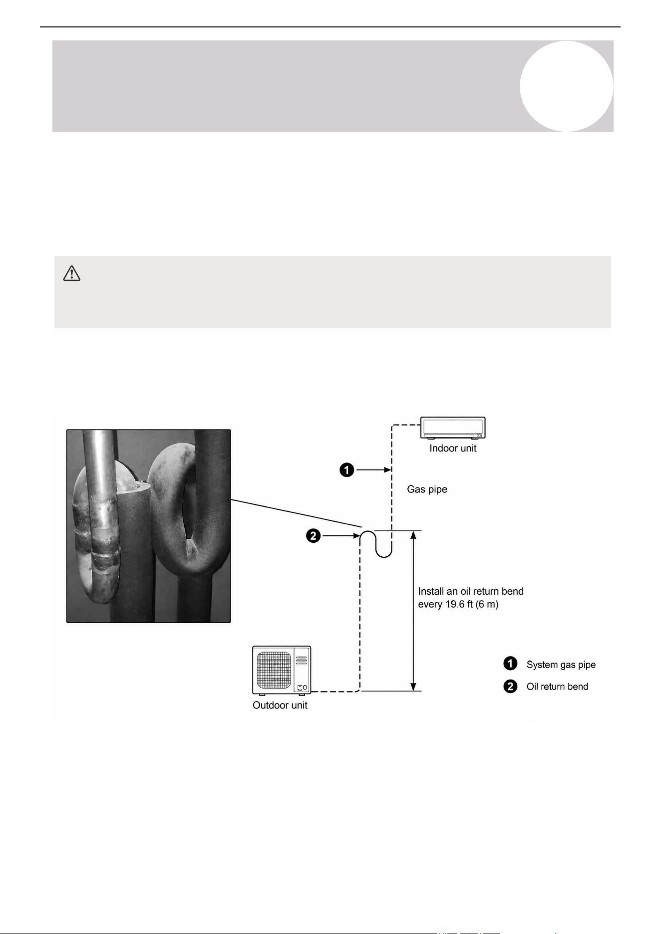
If oil flows back into the outdoor unit's compressor, this might cause liquid compression or deterioration of the
oil return. Oil traps in the rising gas piping can prevent this.
A. Plan the Piping Layout
Before beginning the installation, plan the refrigerant piping layout and connection.
Oil Traps
Outdoor Unit is Beneath the Indoor Unit
Install an oil return bend every 19-feet, 8-¼-inches (6 m). There is no need to add a non-return bend at the
lowest and highest positions of the vertical pipe.
46
Air Conditioner Installation & User Manual
Installation
5
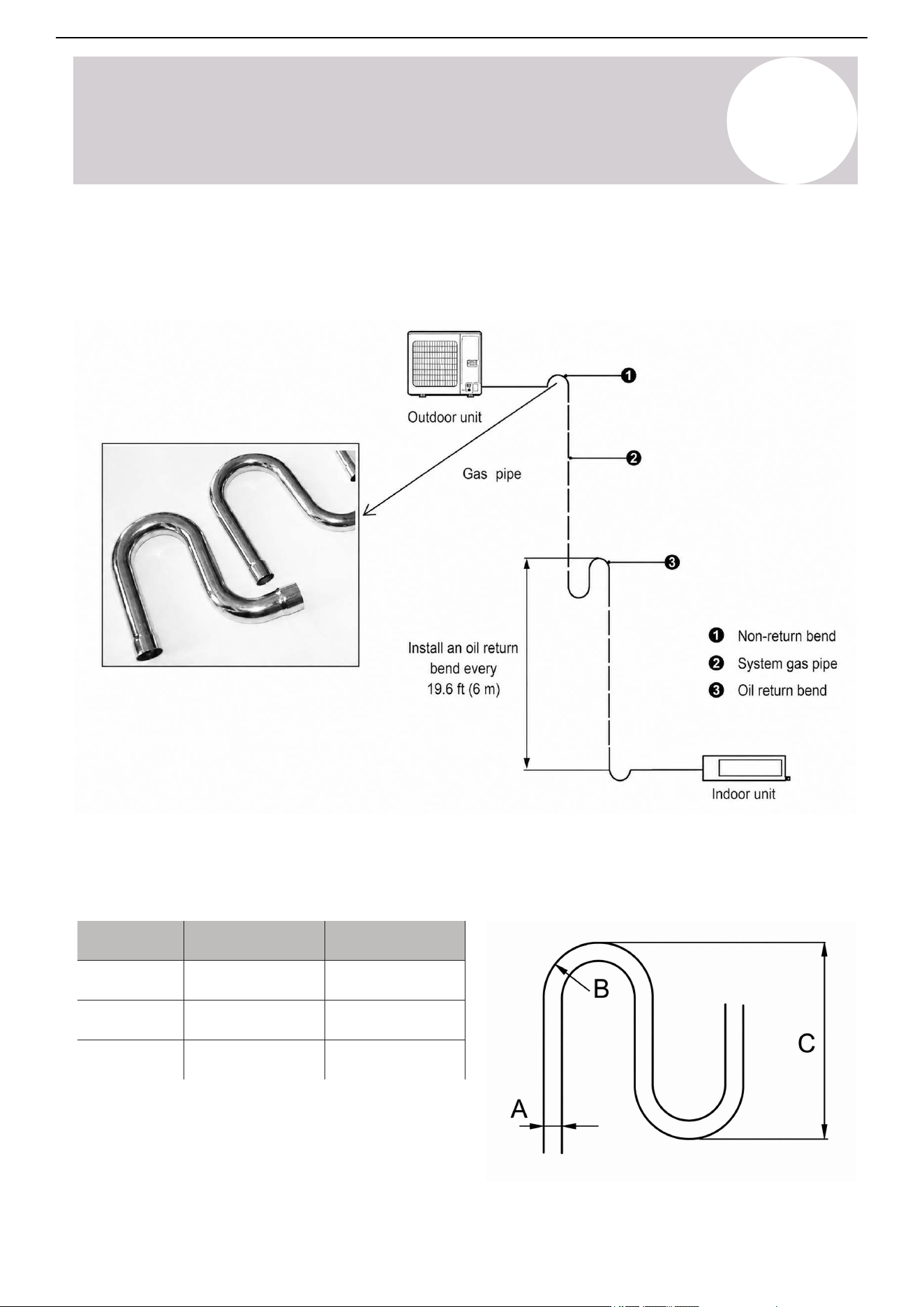
Outdoor Unit is Above the Indoor Unit
Install an oil return bend every 19-feet, 8-¼-inches (6 m). Add the oil return bend and non-return bend at the
lowest and highest positions of the vertical pipe.
A B C
Ø 3/8 in
Ø 1/2 in
Ø 5/8 in
≥ 3/4 in (20 mm)
≤ 5-7/8 in (150 mm)
≥ 1 in (26 mm)
≥ 1-1/4 in (33 mm)
≤ 5-7/8 in (150 mm)
≤ 5-7/8 in (150 mm)
Oil Trap Dimensions
The dimensions for creating the oil return bend are as follows:
47
Air Conditioner Installation & User Manual
Installation
5
B. Unwind the Piping
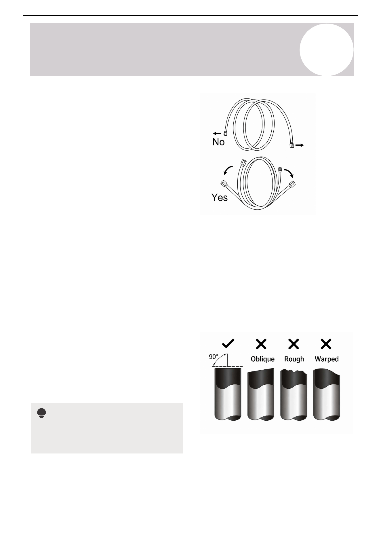
Gently unwind the refrigerant piping against a flat
surface instead of pulling the ends.
• Do not remove the seal caps from the pipe ends
until it is time to connect them, to prevent
contaminants from entering.
• Do not bend the pipe more than three times at
any single point. Be extremely careful not to kink
the piping.
• When bending refrigerant piping, the minimum
bending radius is 4 inches (102 mm).
C. Adjust the Piping Length (Optional)
If needed, precisely cut the refrigerant pipes to the appropriate length to meet the installation requirements.
This guarantees efficient operation and minimizes future maintenance.
Next, remove the burrs from the piping after cutting. This maintains an airtight seal on the refrigerant
connections.
Once the piping is cut and the burrs are removed, flare the pipe ends. Proper flaring is essential to achieve an
airtight seal. If pre-flared refrigerant piping arrives damaged, it can be re-flared.
Cut the Pipes
1. Measure the distance between the indoor and
outdoor units.
2. Use a pipe cutter to cut the pipe a little longer than
the measured distance.
3. Make sure the pipe is cut at a perfect 90-degree
angle.
Note
Be careful not to damage, dent, or deform the
pipe while cutting. This will drastically reduce the
heating efficiency.
48
Air Conditioner Installation & User Manual
Installation
5
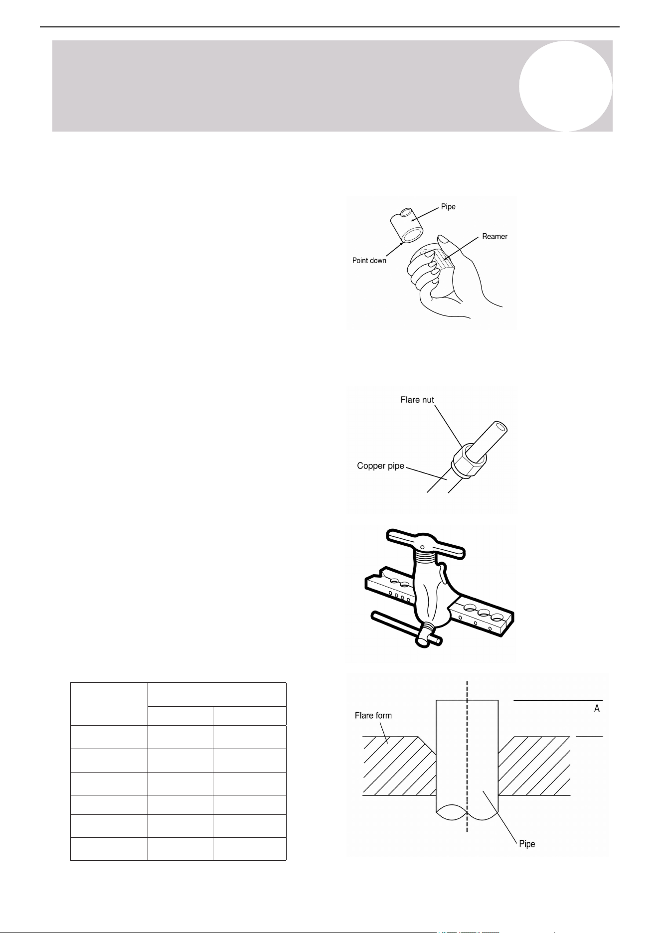
Remove Burrs
1. Hold the pipe at a downward angle to prevent
burrs from falling into the pipe.
2. Use a reamer or deburring tool to remove all the
burrs from the cut section of the pipe.
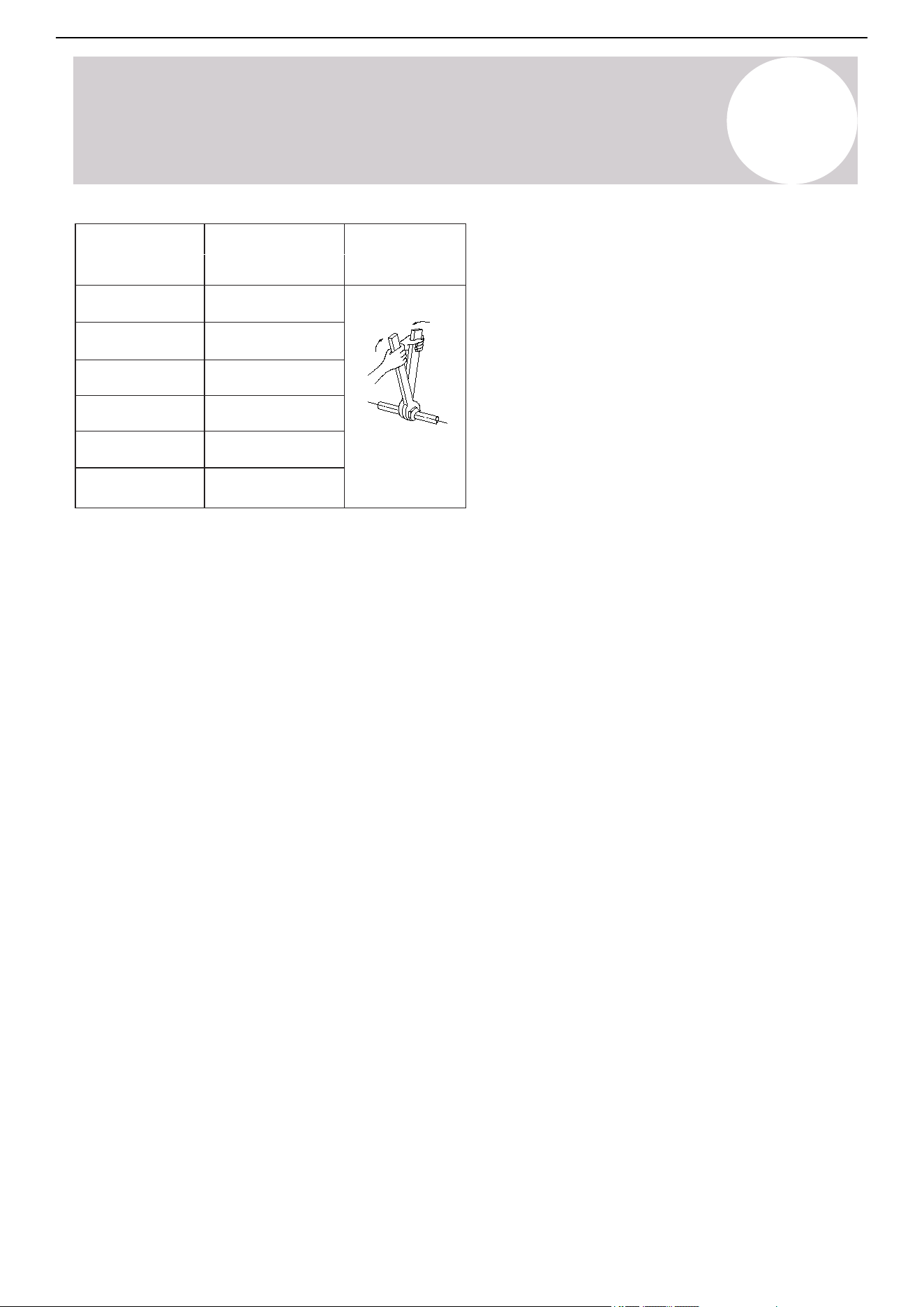
Flare Pipe Ends
1. Seal the pipe ends with PVC tape to prevent
foreign materials from entering.
2. Confirm the pipe was sheathed properly with
insulation material.
3. Place the flare nuts on both ends of the pipe.
Make sure they are facing the correct direction,
because it is not possible to change their direction
after flaring.
4. Remove the PVC tape from the ends of the pipe
when ready to perform the flaring work.
5. Clamp the flare form on the end of the pipe. The
end of the pipe must extend beyond the edge of
the flare form in accordance with the dimensions
shown in the tables:
Pipe Diameter
inch / mm
Flare Dimension A
inch / mm
Min Max
Ø1/4 / Ø6.4 0.33 / 8.4 0.34 / 8.7
Ø3/8 / Ø9.5
0.52 / 13.2
0.53 / 13.5
Ø1/2 / Ø12.7
0.64 / 16.2
0.65 / 16.5
Ø5/8 / Ø15.9
0.76 / 19.2
0.78 / 19.7
Ø3/4 / Ø19
0.91 / 23.2
0.93 / 23.7
Ø7/8 / Ø22.2
1.04 / 26.4
1.06 / 26.9
Piping Extension Beyond Flare Form
49
Air Conditioner Installation & User Manual
Installation
5
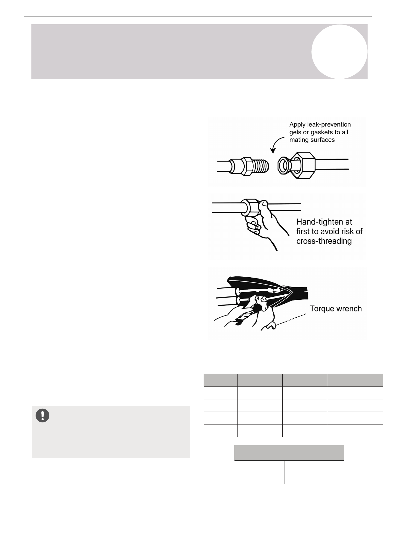
Pipe Diameter
inch / mm
Torque
N.m (lb.ft)
Sketch Map
Ø1/4 / Ø6.35
18~20
(13.3~14.8)
Ø3/8 / Ø9.52
32~39
(23.6~28.8)
Ø1/2 / Ø12.7
49~59
(36.1~43.5)
Ø5/8 / Ø15.9
57~71
(42~52.4)
Ø3/4 / Ø19
67~101
(49.4~74.5)
Ø7/8 / Ø22
85-110
(62.7-81.1)
6. Place the flaring tool onto the form.
7. Turn the flaring tool's handle clockwise until the
pipe is fully flared.
8. Remove the flaring tool and flare form, then
inspect the end of the pipe for cracks and flaring.
D.. Connect the Pipes
Connect the copper pipes to the indoor unit first, then connect it to the outdoor unit. Connect the low-pressure
pipe, then the high-pressure pipe. Use both a spanner and torque wrench when connecting or disconnecting
pipes to the unit.
Once the copper piping kit is unwound, refer to the instructions below:
50
Air Conditioner Installation & User Manual
Installation
5
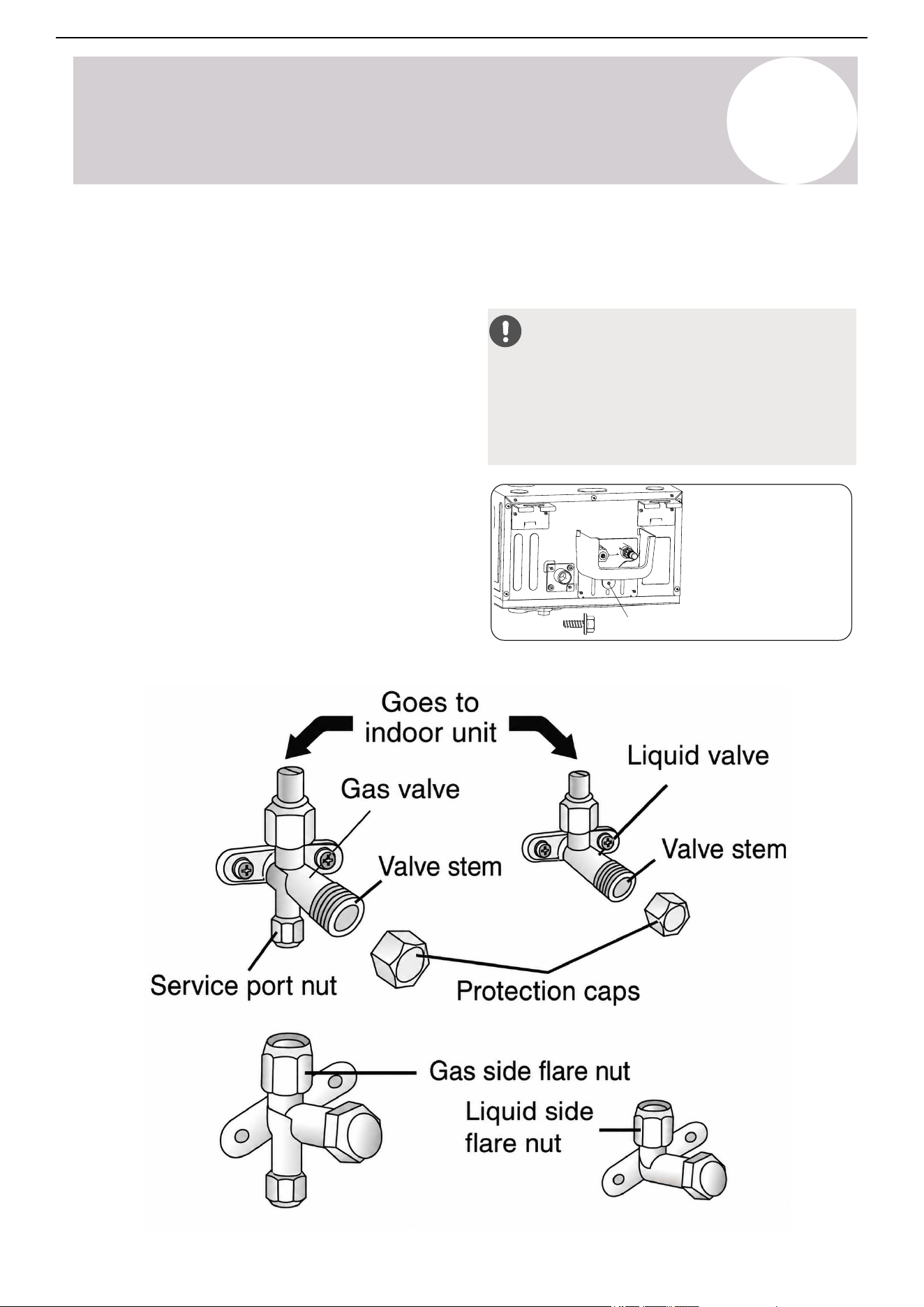
1. Bring the ends of both the copper line and the
indoor unit line together. Align the centers of the
pipes that will be connected.
2. Remove the indoor unit piping cap and check that
no debris is inside. Some gas may be heard
escaping, but it is dry nitrogen to keep the lines
clean.
3. Use any available leak guard or flare sealer on the
piping flares.
4. Attach the flare nut and tighten as much as
possible by hand. Torque correctly to the
specifications found in the table below using two
wrenches.
5. Repeat the process for the other copper line.
6. After connecting the copper pipes to the indoor
unit, wrap the communication cable, drain line, and
refrigerant piping together with binding tape. When
bundling these items, do not intertwine or cross the
communication cable with any other wiring. Keep the
drain line at the bottom so that the water can flow
freely. Ensure the bundle is exiting at a continuous
downward pitch.
7. Thread this pipeline through the wall and connect
it to the outdoor unit. The next page explains how to
connect the pipes to the outdoor unit.
8. Optional: Attach the water receiver (supplied in
the accessories box) to the indoor unit using a
screw.
Indoor Unit
Tightening Torque for
Protection Caps & Flange Connection
Service Port Nut
Protection Caps
[7 - 9] (5-7)
[25 - 30] (18-22)
Φ
Tightening Torque
[N x m] (ft-lbf)
Pipe
Diameter
Tightening Torque
[N x m]
Tightening Torque
[ft-lbf]
Corresponding Stress
(Using a 20 cm wrench)
Wrist Strength
Arm Strength
Arm Strength
Arm Strength
11 - 15
23 - 26
33 - 37
44 - 48
15 - 20
31 - 35
45 - 50
60 - 65
1/4"
(6.4 mm)
Φ
3/8"
(9.5 mm)
Φ1/2"
(12.7 mm)
Φ
5/8"
(15.9 mm)
Excessive force can break the flare nut or
damage the refrigerant piping. Do not exceed the
torque requirements shown in the table.
Do Not Use Excessive Torque
51
Air Conditioner Installation & User Manual
Installation
5
1. Unscrew the cover from the packed valve side of
the outdoor unit.
2. Remove the protective caps from the valve ends.
3. Align the flared pipe end with each valve and
tighten the flare nut as tightly as possible by hand.
4. Use a spanner to grab the body of the valve. Do
not grab the nut that seals the service valve.
5. While firmly gripping the body of the valve, use a
torque wrench to tighten the flare nut according to
the correct torque values.
6. Loosen the flaring nut slightly, then tighten again.
7. Repeat the process for the remaining pipe.
8. Open the stop valves of the outdoor unit to start
the flow of the refrigerant.
Outdoor Unit
CAUTION
After completing the refrigerant piping connection,
check for refrigerant leaks. If a leak is detected,
ventilate the area immediately and evacuate the
system. Refer to Page 59 in the Installation
section for more information.
Two ST4.8*12
screws are supplied,
one of which is spare.
ST4.8*12 screw
52
Some systems require additional charging depending on the pipe lengths. In North America, the standard pipe
length is 25 feet (7.5 m). Charge the refrigerant from the service port on the outdoor unit's low-pressure valve.
Calculate the additional refrigerant to be charged using the following formula:
Refrigerant
R-454B
ؼ in (Ø6.35 mm) Ø⅜ in (Ø9.52 mm) ؽ in (Ø12.7 mm)
(Pipe length - standard
length) x 0.16oz/ft
(Pipe length - standard
length) x 15g/m
(Pipe length - standard
length) x 0.32oz/ft
(Pipe length - standard
length) x 30g/m
(Pipe length - standard
length) x 0.69oz/ft
(Pipe length - standard
length) x 65g/m
Liquid Side Diameter
Air Conditioner Installation & User Manual
Installation
5
E. Charge Additional Refrigerant (If Needed)
CAUTION
Do not mix different types of refrigerant.
53
The joint insulation should be 2~4 inches (51~102 mm) longer than the gap to ensure a proper seal.
Insert the joint insulation into the gap of the existing insulation.
Ensure the joint insulation is securely fastened to the suction and liquid pipes to prevent gaps. Use glue to paste
together the linking part. Do not over-tighten the insulation material. This may compress the air out of the
material, causing poor insulation and early aging.
Notes
• Only insulate the refrigerant piping joints after the refrigerant circuit has been properly vacuumed. Refer
to Page 59 in the Installation section for more information.
• While Pioneer piping comes pre-insulated, installers must still insulate the joints after evacuating the
refrigerant circuit.
F. Insulate the Refrigerant Piping Joints
Air Conditioner Installation & User Manual
Installation
5
• All wiring must comply with local and national electrical codes and regulations. A licensed electrician must
install all the wiring.
• All electrical connections must be made according to the electrical connection diagrams located on the
panels of the indoor and outdoor units.
• If there is a serious safety issue with the power supply, stop work immediately. Explain the reasoning to
the client and refuse to continue the installation until the safety issue is properly resolved.
Power Warnings
• The power voltage must be within 90-110% of the rated voltage. Insufficient power supply can cause a
malfunction, electrical shock, or fire.
• Only connect the unit to an individual branch circuit. Do not connect other equipment to the same power
circuit.
Wiring Warnings
• Firmly connect every wire. Loose wiring can cause the terminal to overheat, resulting in product
malfunction and possible fire.
• Keep the wiring away from the copper tube, as the refrigerant circuit can become extremely hot.
• Do not let wires touch or rest against the refrigerant tubing, compressor, or any moving parts.
• Do not cross the electrical wiring with the signal wiring. This may cause distortion, interference, or possibly
damage the circuit boards.
• Do not house wires of different voltages within the same wire tube. Avoid using metal wire tubes in
environments prone to acid or alkali corrosion; use plastic wire tubes instead.
• Do not place wire connect joints inside the tubing. If a wire connect joint is necessary, use a connection
box at the point of the joint.
WARNINGS
Before performing any electrical work, read these warnings:
General Warnings
5.5. Communication Cable Connection
54
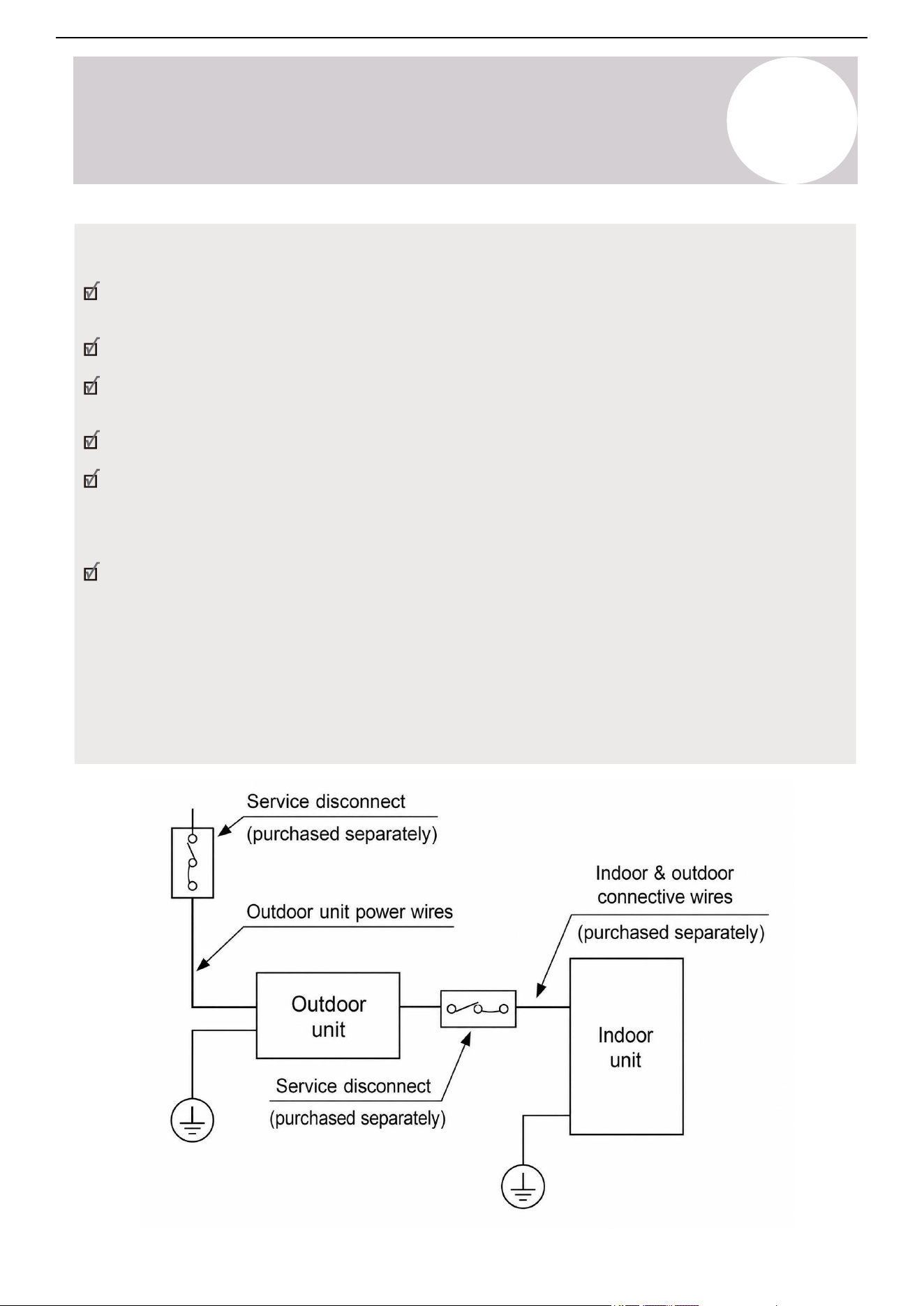
Air Conditioner Installation & User Manual
Installation
5
Prerequisites:
Turn off the main power to the system. After powering off the system, wait 10 minutes or more before
touching the electrical components in order to avoid electrical shock.
Properly ground the system.
If the unit has an auxiliary electric heater, install it at least 3-feet, 3-⅜-inches (1 m) away from any
combustible materials.
Install an external surge suppressor at the outdoor disconnect (recommended).
When connecting power to fixed wiring, incorporate a properly rated, HACR-type circuit breaker or current
leakage protection switch. It must disconnect all poles with a contact separation of at least 1/8 inch (3
mm). Use only an approved switch or circuit breaker with a capacity of 1.5 times the unit's maximum
current.
Service Disconnect: When the air conditioner's maximum current is more than 16A, use a service
disconnect or leakage protection switch with a protective device (purchase separately). When the air
conditioner's maximum current is under 16A, equip the power of the air conditioner with a plug (purchase
separately).
Select the service disconnect as required by local, regional, and national codes. In North America, wire
the appliance according to NEC and CEC requirements.
The cograph is for explanation purposes only. The machine may be slightly different. The actual shape
shall prevail.
55
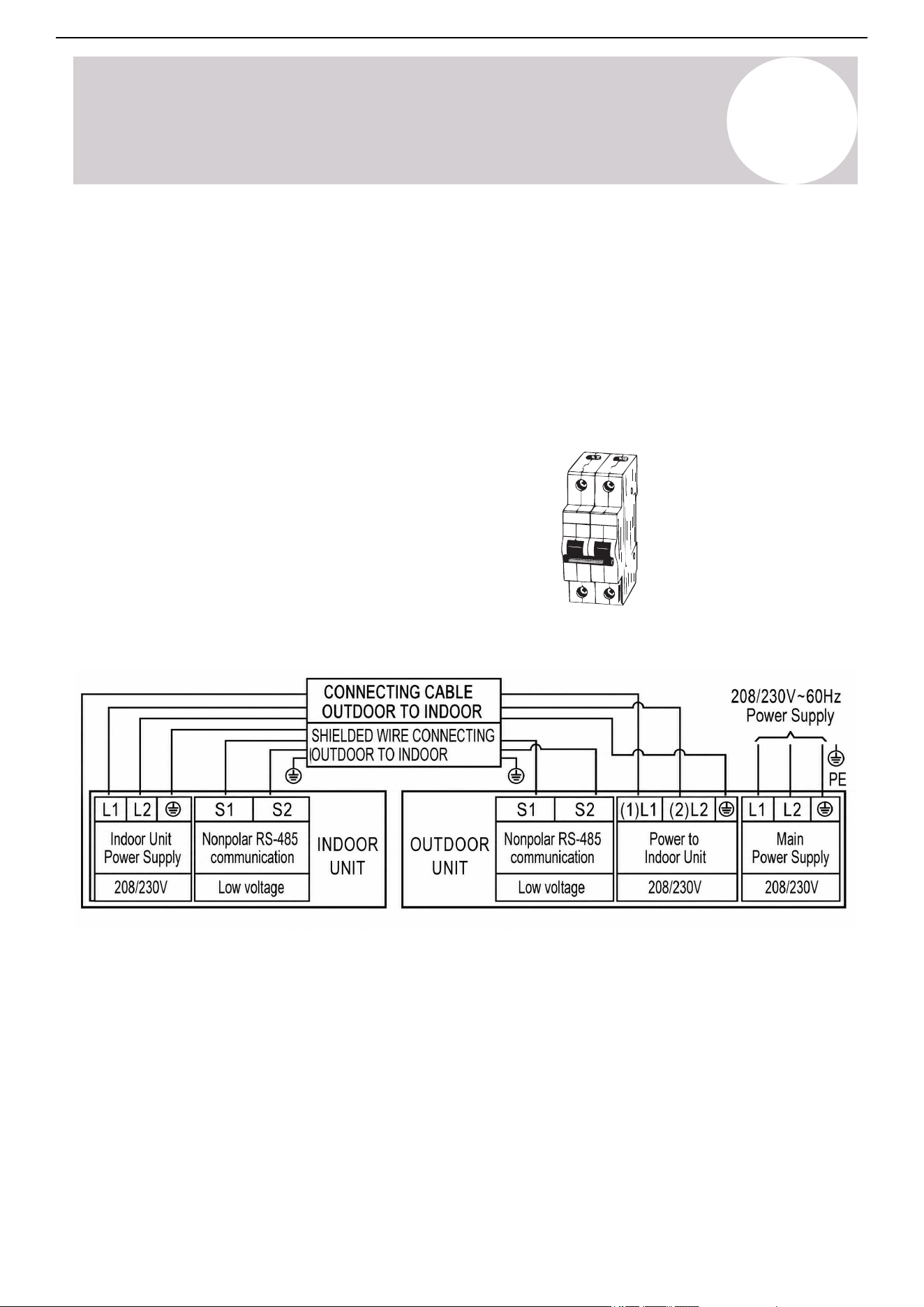
Air Conditioner Installation & User Manual
Installation
5
The 230V systems require a double-pole breaker. The tandem-type
will not work.
The 4-lead communication cable provides two power supply wires, one signal wire, and one ground wire. The
wires are individually insulated and bundled together inside the outer protective jacket. These wires are also pre-
fitted with U-lugs on their ends.
Communication Cable Specifications (All Models): AWG #16 x 4 Core TC-ER cable.
When connecting the communication cable consult the nameplate on the system for detailed electrical
specifications.
Communication Cable Specifications
Connection Diagram
Double-Pole
230V Breaker
56
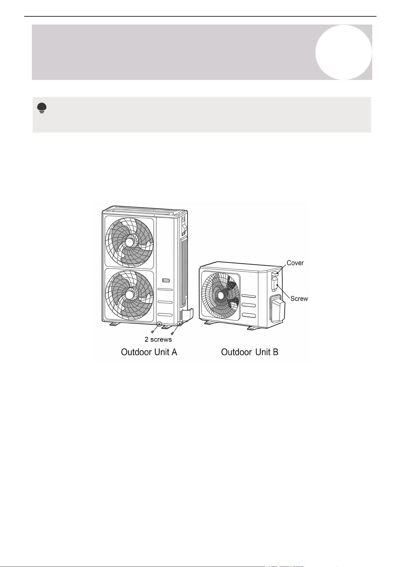
Air Conditioner Installation & User Manual
Installation
5
Note
Connect the outdoor unit wires before the indoor unit wires.
A. Outdoor Unit Wiring
1. Remove the two screws fixed on the front and side panels, then detach the panel to access the wire
connections. (See the Outdoor Unit A figure).
Unscrew the electrical wiring cover and remove it (See the Outdoor Unit B figure).
3. Secure the cable with the clamp. Ensure it is tight and does not pull on the U-lugs.
4. Reattach the panel or cover.
2. Connect the U-lugs to the terminals, matching the numbers with those on the terminal block. There are three
terminals (1, 2, 3) and ground (G). Firmly screw each U-lug to its corresponding terminal. Strictly follow the
wiring diagram inside the electrical box cover when connecting the wires.
Select different wire colors according to the relevant regulations. Ensure the wire colors for the outdoor unit and
terminals match those used for the indoor unit.
Do not connect the power wire to the signal wire terminal. If power and signal wires run parallel, place them in
separate conduits and maintain a distance of at least 11-¾ inches (300 mm).
57
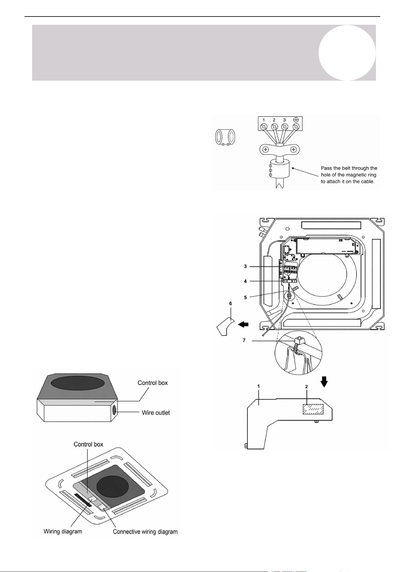
B. Indoor Unit Wiring
1. Open the indoor unit's front panel. Use a
screwdriver to remove the electrical control box
cover.
2. Thread the cable through the wire outlet.
3. Connect the U-lugs to the terminals, matching the
numbers with those on the terminal block. There are
three terminals (1, 2, 3) and ground (G). Firmly screw
each U-lug to its corresponding terminal. Strictly
follow the wiring diagram inside the electrical box
cover when connecting the wires.
Select different wire colors according to the relevant
regulations. Ensure the wire colors for the outdoor
unit and terminals match those used for the indoor
unit.
Do not connect the power wire to the signal wire
terminal. If power and signal wires run parallel, place
them in separate conduits and maintain a distance of
at least 11-¾ inches (300 mm).
4. Secure the cable with the clamp. Ensure it is tight
and does not pull on the U-lugs.
5. Reattach the cover and close the front panel.
Super-Slim Models
Magnetic ring (if supplied with the accessories)
Compact Models
1. Control box lid
2. Wiring diagram label
3. Power supply terminal block
4. Clamp for wiring
5. Wiring between units
6. Plastic cover
7. Clamp (field supply)
Air Conditioner Installation & User Manual
Installation
5
58
Air Conditioner Installation & User Manual
Installation
5
5.6.
Evacuate the Refrigerant Circuit
Prerequisites:
Confirm the pipes connecting the indoor and
outdoor units are properly attached.
Ensure all electrical wiring is connected
properly.
Note:
When opening valve stems, turn the supplied
Allen wrench until the valve stem comes into
contact with the stopper. Do not try to force the
valve to open further.
1. Discharge the oxygen-free nitrogen. Evacuate the system to 8,000 microns (8 Torr) using all service valves.
2. Break the vacuum by introducing nitrogen into the port connections (liquid and gas lines) until achieving
positive pressure.
3. Evacuate the system to a reading of 5,000 Microns (5 Torr).
4. Break the vacuum again by introducing nitrogen into the port connections (liquid and gas lines) until achieving
positive pressure.
5. Evacuate the system to a reading of 500 Microns (0.5 Torr).
6. Hold the vacuum without movement for a minimum of 4 hours to ensure a moisture-free system.
7. If the vacuum fails to hold, repeat the steps until it does.
Reminder: Insulate the Refrigerant Piping Joints
Once the refrigerant circuit is evacuated, remember to insulate the refrigerant piping joints.
For instructions, refer to Page 53 in the Installation section.
CAUTION
Qualified and well-trained personnel must complete the evacuation of the refrigerant circuit.
Air and foreign matter in the refrigerant circuit can lead to abnormal rises in pressure, which can damage the air
conditioner, reduce its efficiency, and cause injury.
Use a vacuum pump and manifold gauge to evacuate the refrigerant circuit, removing any non-condensable gas
and moisture from the system.
Perform the evacuation after the initial installation and when relocating the unit.
59
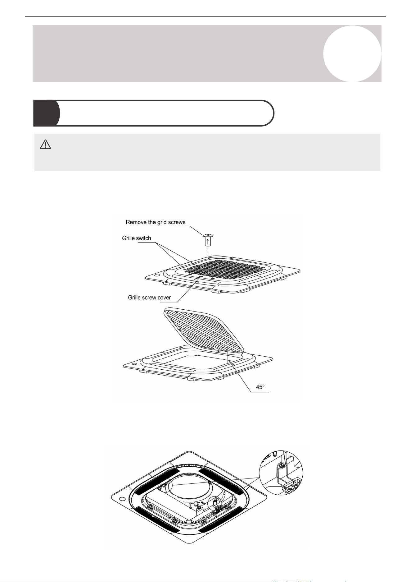
Air Conditioner Installation & User Manual
Installation
5
5.7. Panel Installation
1. To unlock the grill hook, push both of the tabs toward the middle simultaneously.
2. Hold the grille at a 45-degree angle, lift it up slightly, and detach it from the main body.
3. Attach the panel to the indoor unit's hook.
The panel hook is pre-hung to the indoor unit's flow guide ring, as shown:
CAUTION
Do not place the panel face down on the floor, against a wall, or on uneven surfaces.
60
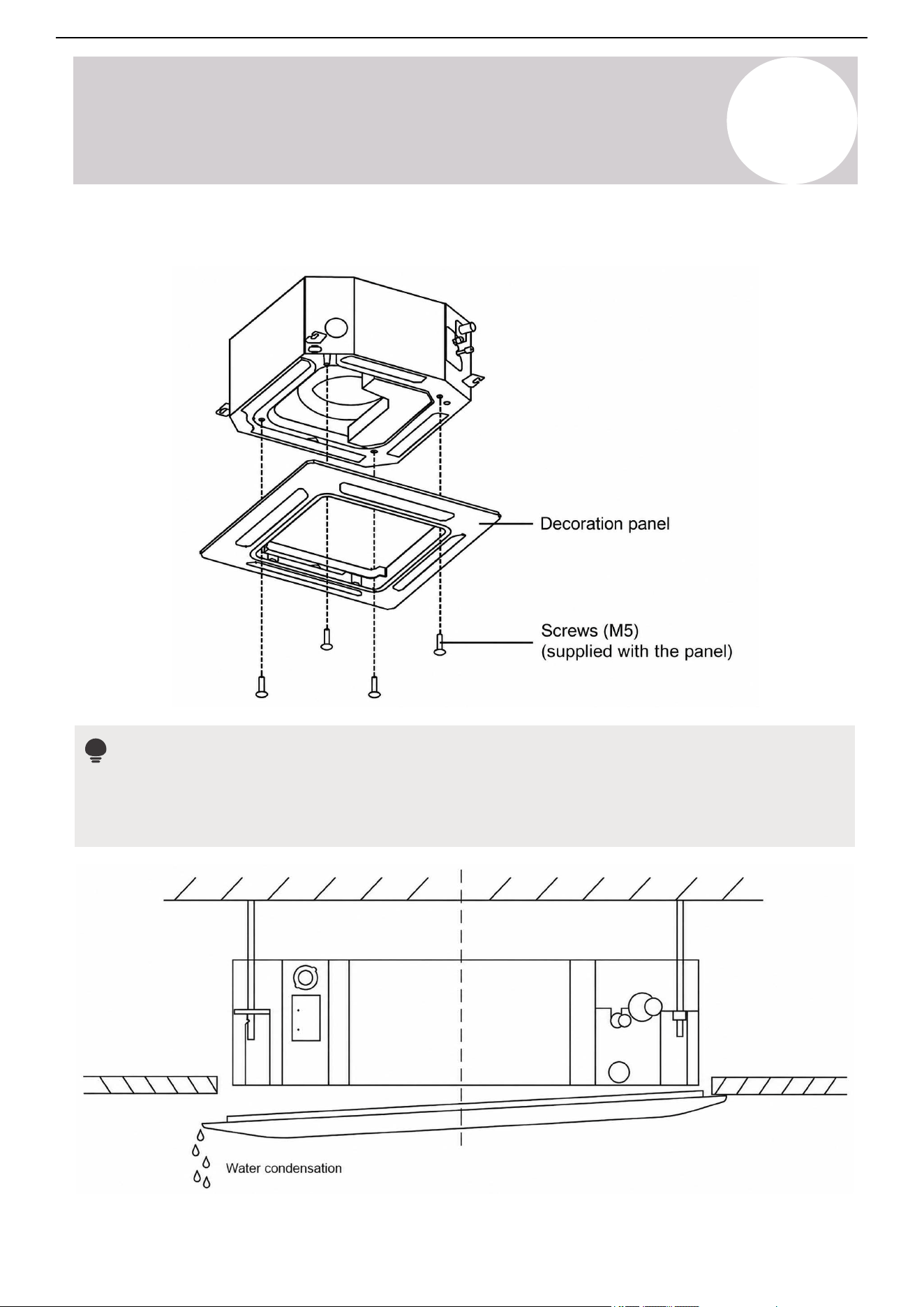
Air Conditioner Installation & User Manual
Installation
5
4. Secure the panel with four screws (M5), as shown:
Note
To adjust the indoor unit's height, use the openings at the four corners of the panel. Make sure the internal
wiring and drain line are not affected by this adjustment. Failure to tighten the screws can cause water
leakage.
61
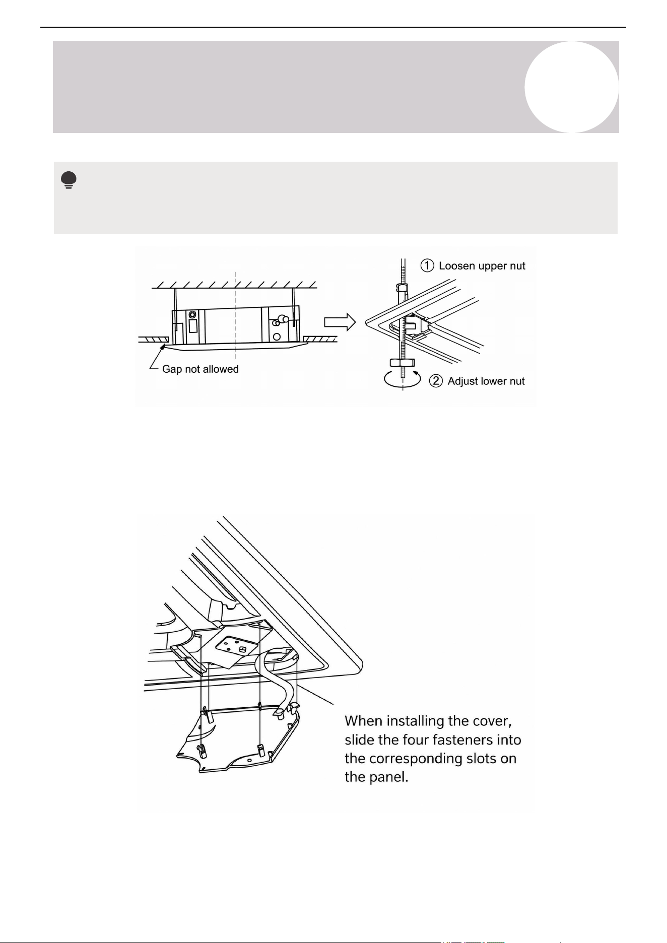
Air Conditioner Installation & User Manual
Installation
5
If the unit is not hung correctly and a gap exists, adjust the unit's height to ensure proper function. Modify the
unit's height by loosening the upper nut and adjusting the lower nut.
5. Hang the intake grille on the panel.
6. Connect the louver motor and control box lead connectors on the panel to the corresponding connectors on
the main body.
7. Reinstall the installation cover into the style grid.
Note
62
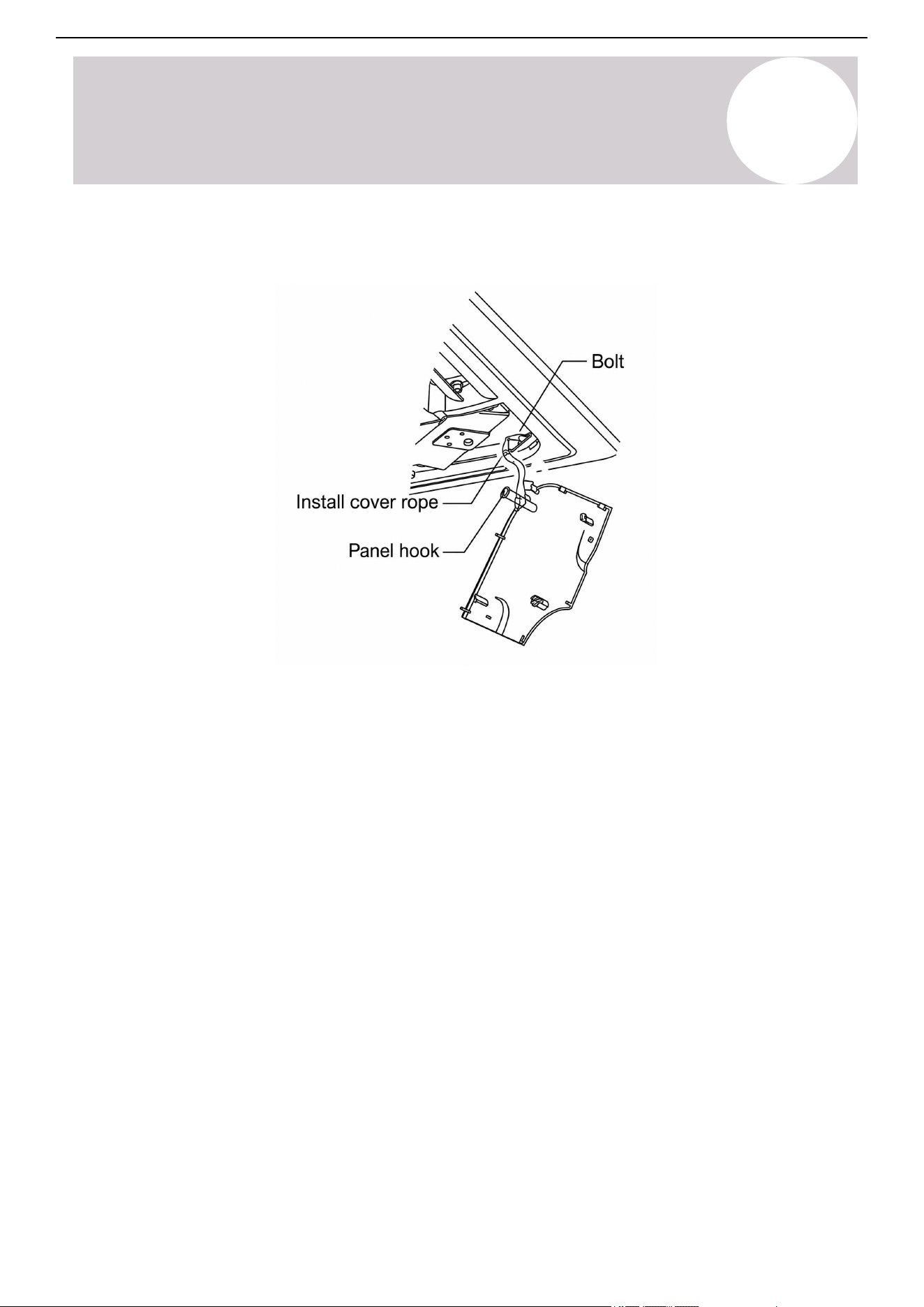
8. Attach the installation cover plate rope to the
installation cover plate's pillar, then gently press the cover plate
into the panel.
9. After installation, place the plugs of the display, swing, water pump, and other wire bodies into the electric
control box.
Air Conditioner Installation & User Manual
Installation
5
63
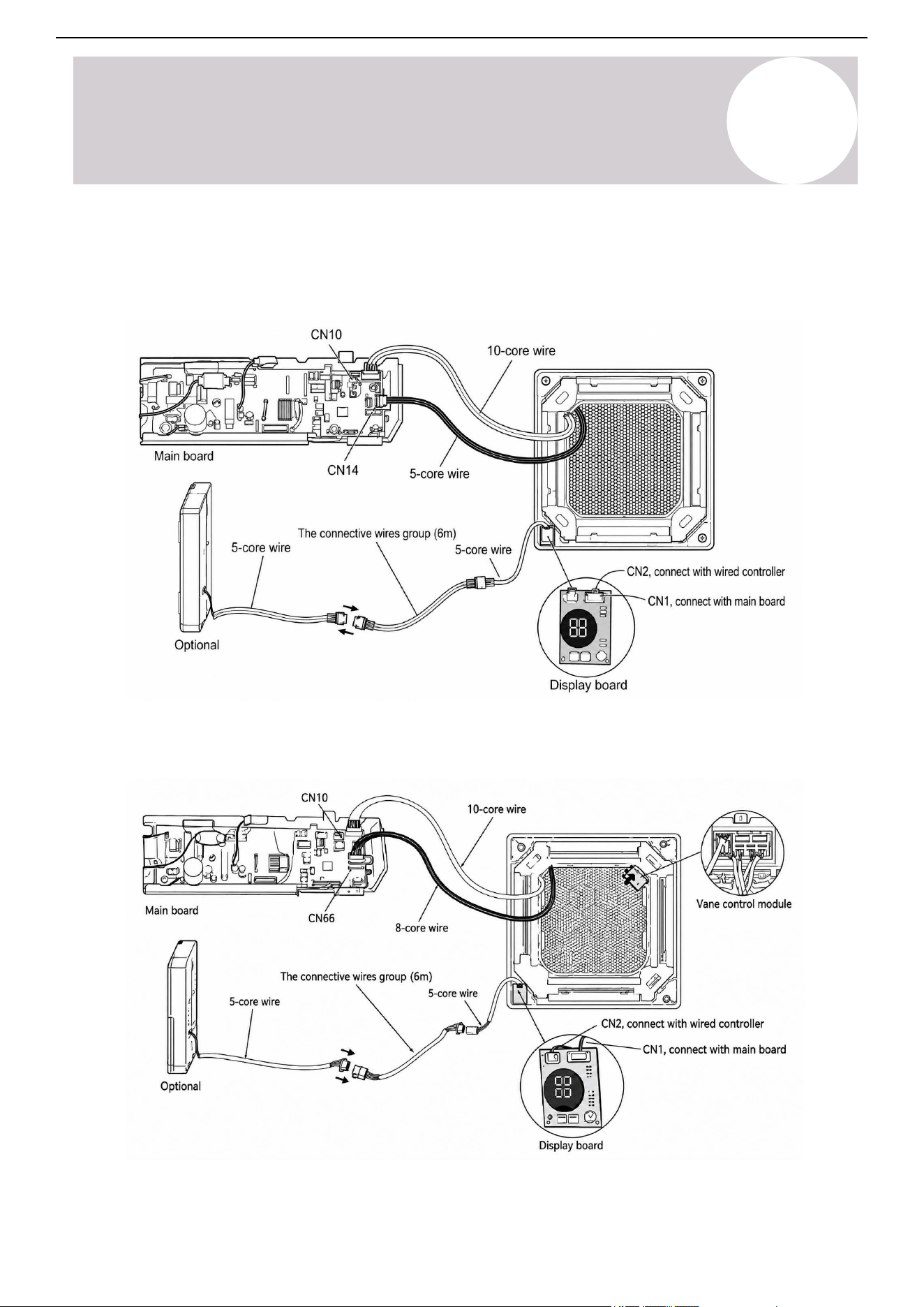
Air Conditioner Installation & User Manual
Installation
5
The display board CN2
attaches to a connecting cable.
For panels with a vane control module, the display board CN1 connects to the main control board CN10. The
vane control motor cable connects to the main control board CN66.
Connection Diagrams
For panels without a vane control module, the display board CN1 connects to the main control board CN10. The
motor cable connects to the main control board CN14.
64
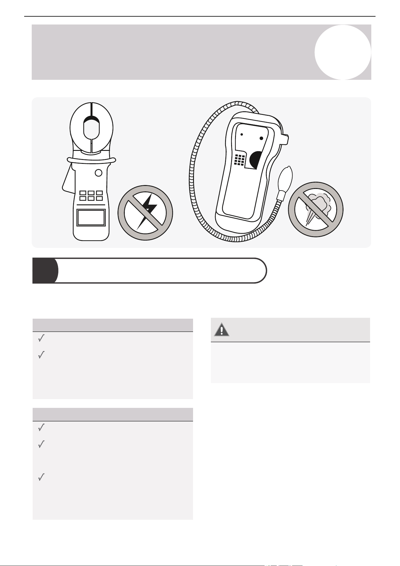
Air Conditioner Installation & User Manual
6
Leak Checks & Test Run
After installation, confirm that the unit's electrical system is safe and operating properly. Electrical leak checks
are required before and during the test run.
Warning –
Risk of Electric Check
All electrical wiring must comply with the
installation manual and local and national
regulations. All work must be performed by a
licensed electrician.
Before Test Run
Check grounding work.
Measure the grounding resistance with a
grounding resistance tester. Grounding
resistance must be less than 4Ω.
This may not be required in some locations.
During Test Run
Check for electrical leakage.
During the test run, use an electroprobe and
multimeter to perform a comprehensive
electrical leakage test.
If electrical leakage is detected, turn off the
unit immediately and call a licensed electrician
to find and resolve the cause of the leakage.
This may not be required in some locations.
Electrical Leak Checks
6.1.
65
Air Conditioner Installation & User Manual
Confirm the system is not leaking gas. Gas leak checks are required before and during the test run.
Before Test Run
Check all flare nut connections to ensure the
system is leak-free.
Confirm that both the gas and liquid valves
(high/low) are 100% fully opened.
During Test Run
During operation, the pressure of the
refrigerant circuit will increase. This may
reveal leaks that were not present during the
initial leak check. Take time to double-check
that all copper pipe connection points are leak
free.
Gas Leak Checks
There are two methods to check for gas leakage:
Soap & Water Method
Use a soft brush to apply soapy water or liquid
detergent to all pipe connection points on the
indoor and outdoor units. The presence of
bubbles indicates a leak.
Leak Detector Method
If using a leak detector, refer to the device's
operation manual for proper usage instructions.
After Test Run
After confirming that all the pipe connection
points do not leak, replace the valve cover on
the outdoor unit.
Gas Leak Checks
6.2.
6
Leak Checks & Test Run
66
Air Conditioner Installation & User Manual
Test Run
6.3.
Perform the test run only after the system is fully installed and the electrical and gas leak checks are complete.
Before Test Run
Electrical Safety Checks
Confirm the unit's electrical system is safe
and operating properly.
Gas Leak Checks
Check all flare nut connections and confirm
the system is not leaking.
Valve Checks
Confirm that both the gas and liquid valves
(high/low) are 100% fully opened.
Test Run Instructions
Perform the following test run for 30 minutes:
1. Connect power to the unit.
2. Press the On/Off button on the remote controller
to turn it on.
3. Press the Mode button to scroll through the
following functions, one at a time.
• Cooling - Select the lowest temperature.
• Heating - Select the highest temperature.
4. Let each function run for 5 minutes and perform
the following checks:
After Test Run Completion
After the 10 boxes above have been checked and marked as passed, perform the following operation:
1. Use the remote control to return the system to a normal desired operating temperature.
2. Use insulation tape to wrap the indoor unit's refrigerant pipe connections that were left uncovered during
the installation process.
If Ambient Temperatures Are Too High to Run a Heating Test:
If outside temperatures are too high to permit Heating mode on the remote controller, do the following:
1. Turn the unit on and put it in Heating mode using the emergency button.
2. Run the Heating mode test as normal and turn the unit back off using the button when complete.
o Water drains from the drain line properly
o All piping is properly insulated
o Indoor unit responds to the remote controller
o Indoor unit louvers work properly
o System works in both Heating & Cooling mode
o No electrical leaks or abnormal noises
o Unit is properly grounded
o All electrical terminals are properly covered
o Indoor and outdoor units are securely installed
o All pipe connections points do not leak
Pass/Fail?
6
Leak Checks & Test Run
67
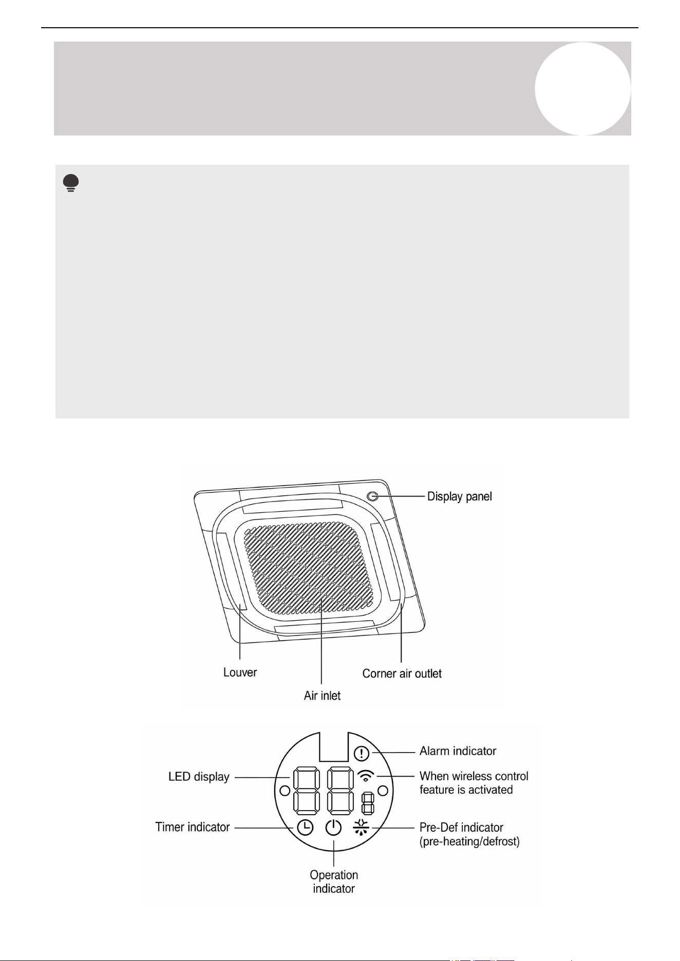
Air Conditioner Installation & User Manual
Indoor Unit Display
Notes
• Different models have different front panels and display windows. The indicators described below may not
be available for your air conditioner.
• Illustrations in this manual are for explanatory purposes. The actual shape of the indoor unit may differ
slightly. The actual shape shall prevail.
• The display panel on the indoor unit can be used to operate the unit in case the remote control has been
misplaced or is out of batteries.
• Each time the air conditioner is powered on, a buzzing sound will be heard to indicate that the product has
been powered on normally. If there is no sound, it is possible that the unit is operating abnormally. Power
on the unit again or check the circuit.
• The actual functions are subject to the product that was purchased. Check the indoor display and remote
control of the air conditioner. See the Remote Controller manual for information on more features.
68
Operating Instructions
7
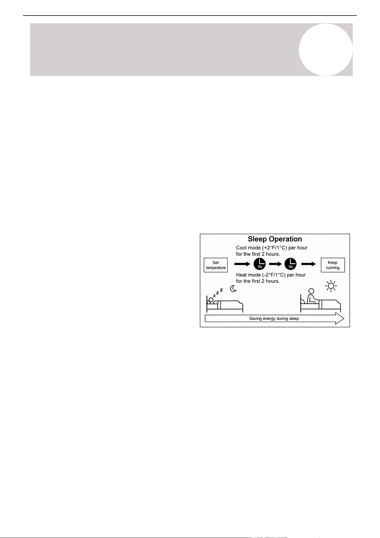
Air Conditioner Installation & User Manual
Sleep Operation
This function decreases energy use during sleeping
hours. The function doesn't need the same
temperature settings to stay comfortable. Use the
remote control to activate this function. The Sleep
function is not available in Fan or Dry mode.
Press the Sleep button to activate this function.
When in Cooling mode, the unit will increase the
temperature by 2°F (1°C) after 1 hour, then
increase by an additional 2°F (1°C) after another
hour. When in Heating mode, the unit will decrease
the temperature by 2°F (1°C) after 1 hour, then
decrease by an additional 2°F (1°C) after another
hour. The feature will stop after 8 hours and the
system will keep running with the final situation.
Refrigerant Leakage Detection
When the system detects a refrigerant malfunction,
the indoor unit will automatically display the following
error codes:
o EL0C: System lacks refrigerant.
o EHC1: Refrigerant sensor detects leakage.
o EHC2: Refrigerant sensor's operating condition
is out of range and leakage is detected.
o EHC3: Refrigerant sensor's operating condition
is out of range.
o ECC1: The other indoor unit refrigerant sensor
detects leakage (multi-zone systems).
EHC1, EHC2, EHC3, and ECC1 error codes are
only applicable for units with refrigerant sensors.
When EHC1 or EHC2 errors occur, the buzzer will
continue to beep for 5-6 minutes before stopping.
Pressing any button on the remote control will also
stop the buzzer.
Features
Off Mode
When the display panel is turned off, the unit turns
off and the remote control is re-enabled.
Default Setting
When the air conditioner restarts after a power
failure, it will default to the factory settings (Auto
mode, Auto fan, 76°F/24°C). A power failure may
cause inconsistencies on the remote control and
panel. Use the remote control to update the status.
Auto-Restart
If a power failure occurs, the system will immediately
stop. When power returns, the operation light on the
indoor unit will flash. Press the On/Off button on the
remote control to restart the unit. If the system has
an auto-restart function, the unit will restart using the
same settings.
3-Minute Protection Failure
A protection feature prevents the air conditioner from
activating for approximately 3 minutes when it
restarts immediately after operation.
Louver Angle Memory Function
This function is only available for units with the
louver angle memory function. When the unit restarts
after a power failure, the angle of the horizontal
louvers will automatically return to the previous
position. The angle of the horizontal louver must not
be set too small, as condensation may form and drip
into the machine. To reset the louver, press the
manual button, which will reset the horizontal louver
settings.
Heat Exchanger Dust Removal Function
This feature helps keep the outdoor coil cleaner and
may extend the duration between regular
maintenance intervals depending on the local
conditions. When the unit is turned off, a delay
occurs when the outdoor fan runs in reverse rotation
for 70 seconds to blow off loose accumulated dust
and debris.
Forced Cooling Mode
In this mode, the operation light flashes. The system
will turn to Auto mode after it has cooled with a high
wind speed for 30 minutes. The remote control will
be disabled during this operation.
69
Operating Instructions
7
Air Conditioner Installation & User Manual
8
Maintenance
CAUTION
• Always turn off the system and disconnect its power supply before cleaning or performing maintenance.
• An authorized dealer or licensed service provider must perform the removal and maintenance of the filter.
• When removing the filter, do not touch metal parts in the unit. The sharp metal edges can cut you.
• Do not expose the filter to direct sunlight when drying. This can shrink the filter.
• An authorized dealer or licensed service provider must perform any maintenance on the indoor and
outdoor unit.
• Do not wash the unit under running water, as this will create an electrical hazard.
• Only use a soft, dry cloth to wipe the unit clean. If the unit is especially dirty, use a cloth soaked in warm
water to wipe it clean.
• Do not use chemicals or chemically treated cloths to clean the unit.
• Do not use paint thinner, polishing powder, or other solvents to clean the unit. They can cause the plastic
surface to crack or deform.
• Do not use water to clean the inside of the indoor unit. This can destroy insulation and cause electrical
shock.
• Do not use water hotter than 104°F (40°C) to clean the front panel. This can cause the panel to deform or
become discolored.
• The cooling efficiency of the unit and your health could be damaged by the clogged AC. Make sure to
clean the filter every two weeks.
• In households with animals, periodically wipe down the grille to prevent animal hair from blocking the
airflow.
• Do not substitute a blown fuse with a higher or lower amperage rating fuse, as this may cause circuit
damage or an electrical fire.
70
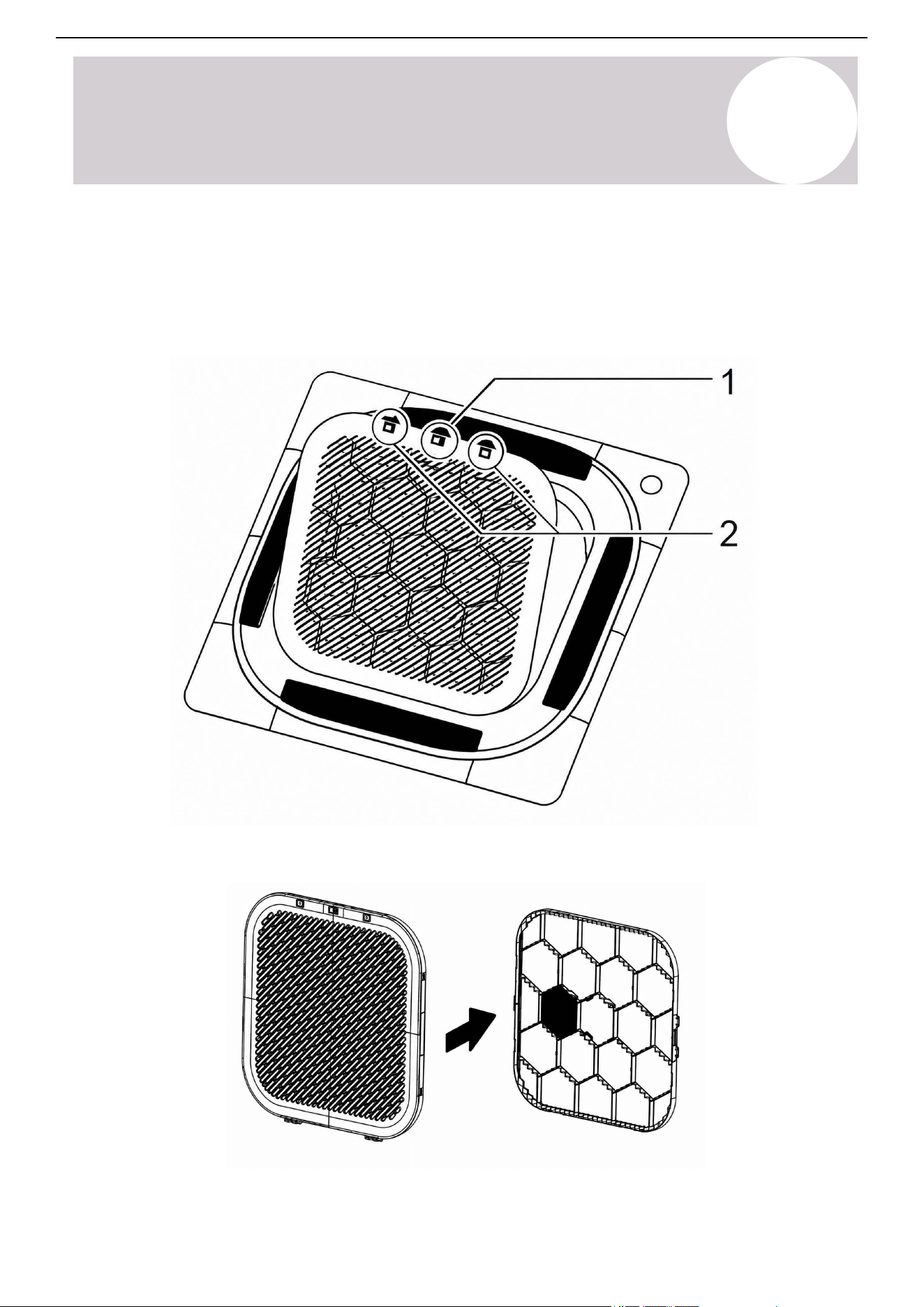
Air Conditioner Installation & User Manual
3.. Separate the frame from the filter assembly.
1. Open the screw cover and twist out the screw.
2. Press the buttons on both sides to pull out the air inlet frame.
Clean the Indoor Unit's Air Filter
8
Maintenance
71
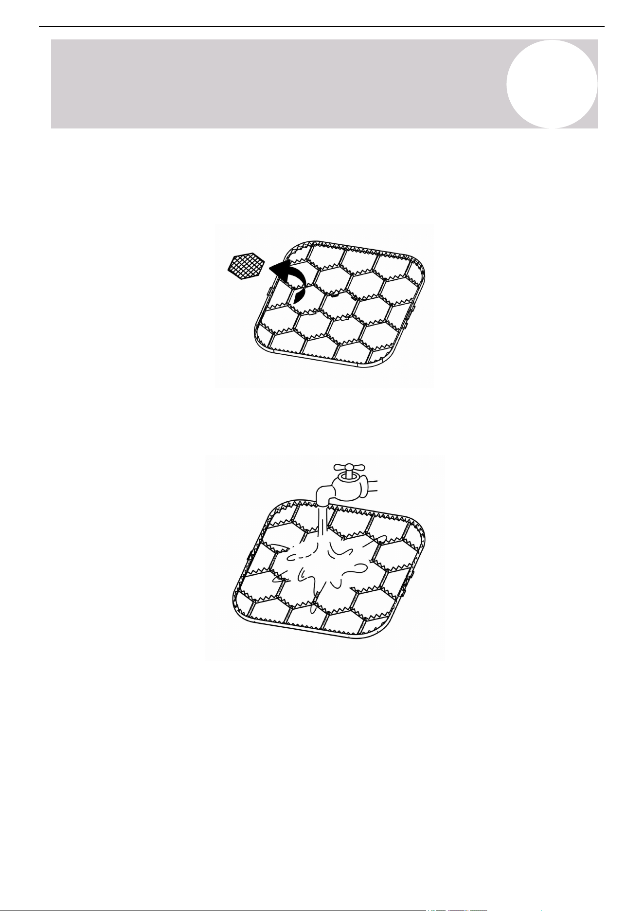
Air Conditioner Installation & User Manual
4. Clean the filter assembly.
5. Optional: Remove the fresh air filter. The fresh air filter cannot be cleaned with water. It is recommended to
replace it regularly.
6. Clean the air filter by vacuuming the surface or washing it in warm water with mild detergent.
If using water, the inlet side should face down and away from the water stream.
8
Maintenance
72
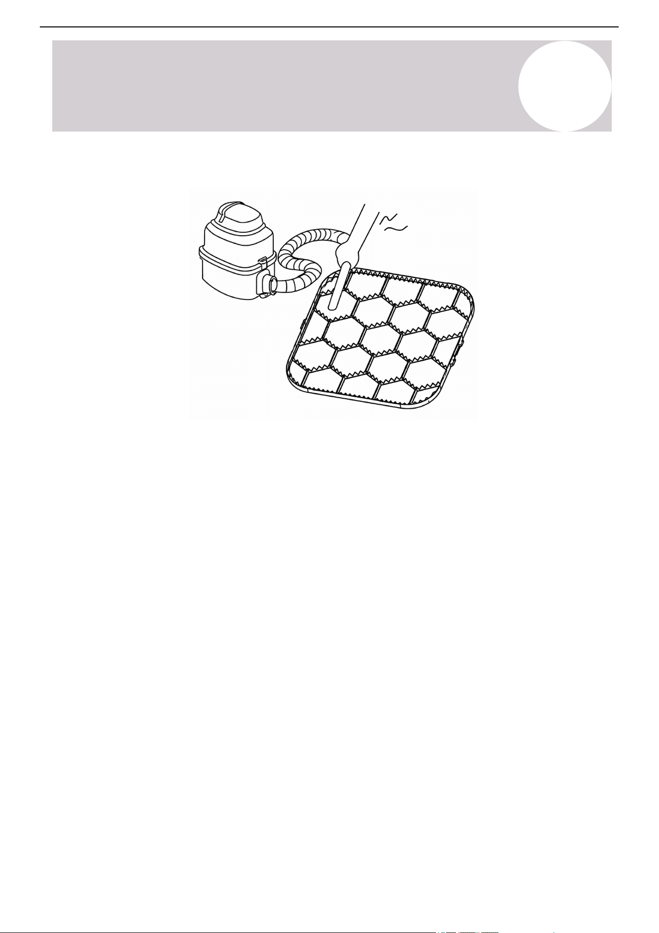
Air Conditioner Installation & User Manual
If using a vacuum cleaner, the inlet side should face the vacuum.
7. If the filter was cleaned with water, allow it to air-dry.
8. Reinstall the filter.
8
Maintenance
73
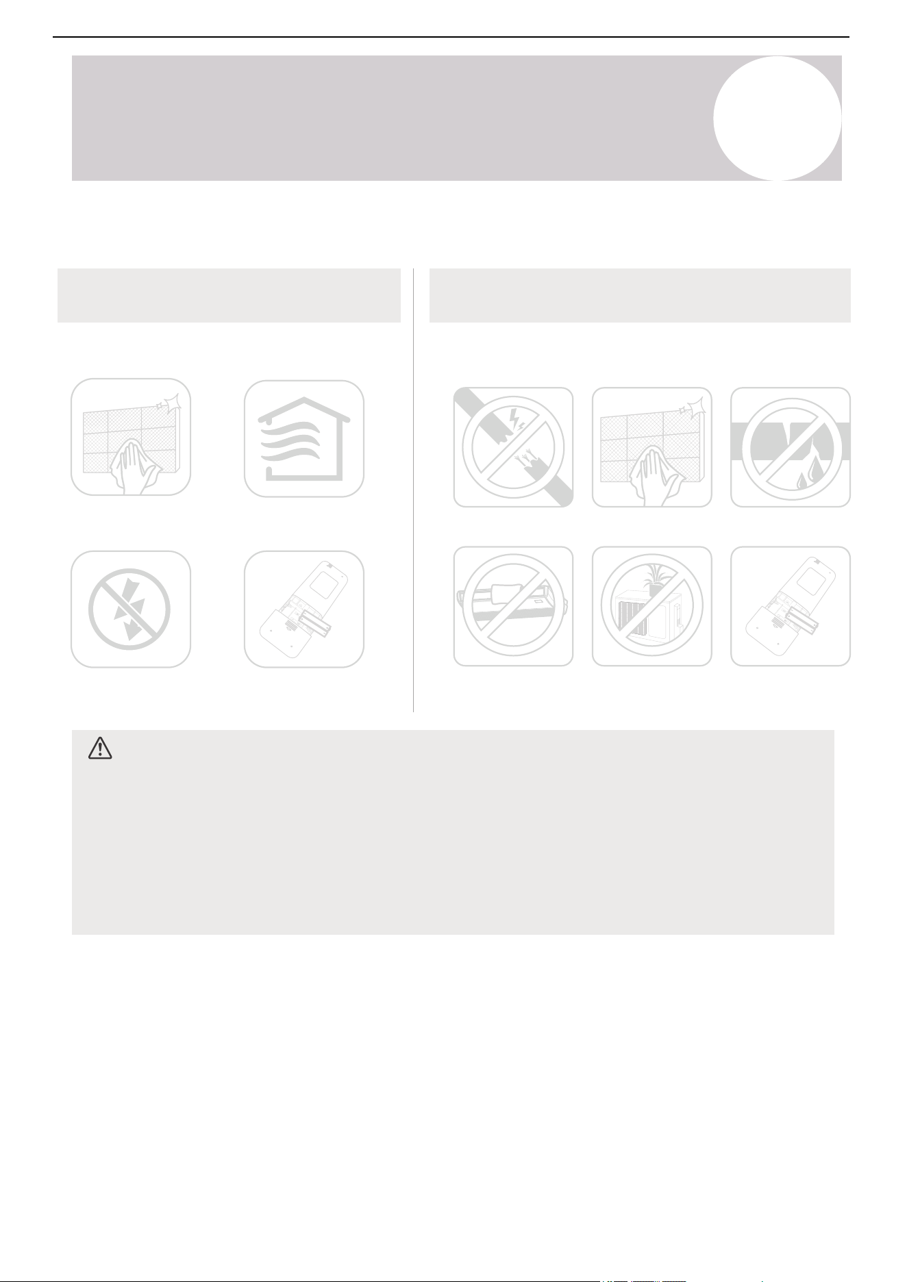
Air Conditioner Installation & User Manual
Maintain the AC
Maintenance -
Long Periods of Non-Use
Maintenance -
Pre-Season Inspection
After long periods of non-use or before periods of frequent
use, do the following:
Clean all filters
Turn on the Fan function until the
unit dries out completely
Turn off the unit and
disconnect the power
Remove the batteries from the
remote control
Check for damaged wires
Clean all filters
Check for leaks
Make sure nothing is blocking the air inlets
and outlets
Replace the
batteries
If the air conditioner won't be used for an
extended period of time.
CAUTION
If any of the following conditions occur, turn off the unit immediately:
o The power cord is damaged or abnormally warm.
o A burning odor is present.
o The unit is emitting loud or abnormal sounds.
o A power fuse blows or the circuit breaker frequently trips.
o Water or other objects fall into or out of the unit.
Do not attempt to fix these problems by yourself. Contact an authorized service provider immediately.
8
Maintenance
74
Air Conditioner Installation & User Manual
Unit does not turn on when
pressing the On/Off button
Unit changes from
Cooling/Heating mode
to Fan mode
Indoor unit emits white
mist
Indoor and outdoor units
emit white mist
Indoor unit makes noises
Indoor and outdoor units
make noises
The unit has a 3-minute protection feature that prevents the unit from overloading. The
unit cannot be restarted within 3 minutes of being turned off.
Cooling and Heating mode: If the operation light and PRE-DEF (pre-heating/defrost)
indicators are lit up, the outdoor temperature is too cold, activating the unit's anti-cold
wind feature in order to defrost the unit.
In Cooling-only mode: If the Fan-Only indicator is lit up, the outdoor temperature is
too cold, activating the unit's anti-freeze protection in order to defrost the unit.
The unit may change its settings to prevent frost from forming on the unit. Once the
temperature increases, the unit will start operating in the previously selected mode
again.
The set temperature has been reached, at which point the unit turns off the
compressor. The unit will continue operating when the temperature fluctuates again.
In humid regions, a large temperature difference between the room's air and the
conditioned air can cause white mist.
When the unit restarts in Heating mode after defrosting, white mist may be emitted
due to moisture generated from the defrosting process.
A rushing air sound may occur when the louver resets its position.
A squeaking sound is heard when the system is off or in Cooling mode. The noise is
also heard when the drain pump (optional) is in operation.
A squeaking sound may occur after running the unit in Heating mode,
due to expansion and contraction of the unit's plastic parts.
Low hissing sound during operation: This is normal and caused by refrigerant
gas flowing through both the indoor and outdoor units.
Low hissing sound when the system starts, stops running, or defrosting: This noise is
normal and caused by the refrigerant gas stopping or changing direction.
Squeaking sound: Normal expansion and contraction of plastic and metal parts
caused by temperature changes during operation can cause squeaking noises.
Issue
Possible Causes
The following issues are not malfunctions and will not require repairs in most situations:
Common Issues
T
Troubleshooting
CAUTION
o
If any of the following conditions occur, turn off the unit immediately:
o
The power cord is damaged or abnormally warm.
o
A burning odor is present.
o
The unit is emitting loud or abnormal sounds.
o
A power fuse blows or the circuit breaker frequently trips.
Water or other objects fall into or out of the unit.
Do not attempt to fix these problems by yourself. Contact an authorized service provider immediately.
75
Air Conditioner Installation & User Manual
Problem
Possible Causes
Solution
Poor Cooling
Performance
Temperature setting may be higher
than ambient room temperature.
Heat exchanger on the indoor or
outdoor unit is dirty.
Air filter is dirty.
Air inlet or outlet of either unit is
blocked.
Doors and windows are open.
Excessive heat is generated by sunlight.
Too many sources of heat in the room
(people, computers, electronics, etc.).
Low refrigerant due to leak or long-
term use.
Lower the temperature setting.
Clean the affected heat exchanger.
Remove the filter and clean it according
to the instructions in this manual.
Turn the unit off, remove the obstruction, and
turn it back on.
Make sure that all doors and windows are
closed while operating the unit.
Close windows and curtains during periods
of high heat or bright sunshine.
Reduce the amount of heat sources.
Check for leaks. Reseal if necessary and top
off the refrigerant.
When trouble occurs, check the following points before contacting a repair company:
Outdoor unit
makes noises
Dust is emitting from
either the indoor or
outdoor unit
Unit emitting bad odor
Outdoor unit's fan
does not operate
The outdoor unit will make different sounds based on its current operating mode.
The unit may accumulate dust during extended periods of non-use, which will be emitted
when the unit is turned on. This can be mitigated by covering the unit during long periods
of inactivity.
The unit may absorb odors from the environment, which will be emitted during
operations. Examples are furniture, cooking, cigarettes, etc.
The unit's filters have become moldy and need to be cleaned.
During operation, the fan speed is controlled to optimize product operation.
Issue
Possible Causes
T
Troubleshooting
If the problem persists, contact a local dealer or the nearest customer service center. Provide them with a
detailed description of the unit malfunction and model number.
Note
76
Air Conditioner Installation & User Manual
Poor heating
performance
Unit starts and stops
frequently
Unit is not operating
Outdoor temperature is
extremely low.
Cold air is entering through
doors and windows.
Low refrigerant due to leak
or long-term use.
Use an auxiliary heating device.
Make sure that all doors and windows are
closed during use.
Check for leaks. Reseal if necessary and top off
refrigerant.
There's too much or little
refrigerant in the system.
Incompressible gas or moisture
has entered the system.
System circuit is blocked.
Compressor is broken.
Voltage is too high or low.
Check for leaks and recharge the system
with refrigerant.
Evacuate and recharge the system with refrigerant.
Determine which circuit is blocked and replace
the malfunctioning piece of equipment.
Replace the compressor.
Install a manostat to regulate the voltage.
Power failure.
Power is turned off.
Fuse is burned out.
Remote control batteries
are dead.
The unit's 3-minute protection
has been activated.
The unit's timer is activated.
Wait for the power to be restored.
Turn on the power.
Replace the fuse.
Replace the batteries.
Wait 3 minutes after restarting the unit.
Turn the timer off.
Problem
Possible Causes
Solution
T
Troubleshooting
Indicator lamps
continue to flash
Error codes appear and
begin with the letters as
the following in the
window display of the
indoor unit:
• E (x), P (x), F (x)
• EH (xx), EL (xx),
EC (xx)
• PH (xx), PL (xx),
PC (xx)
The unit may stop operating or continue to run safely. If the indicator lamps
continue to flash or error codes appear, wait about 10 minutes. The problem may
resolve itself.
If not, disconnect the power. Then, connect the power again and turn the unit on.
If the problem continues after performing the checks and diagnostics above, turn off
the unit immediately and contact an authorized service center.
The design and specifications are subject to change without prior notice for product
improvements. Consult with the sales agency or manufacturer for details. Any
updates to the manual will be uploaded to the service website, check for the latest
version.
77

The design and specifications of this product are subject to change without prior notice
as development continues. Consult with the sales agency or manufacturer for details.
Refer to the equipment nameplate for all other applicable specifications.
Copyright © Parker Davis HVAC International, LLC. All rights reserved.
is a registered trademark of Parker Davis HVAC International, LLC.
Parker Davis HVAC International
7290 NW 77 Court, Miami, FL 33166 - USA
Tel
: (305) 513-4488
Fax
: (305) 513-4499
E-mail
Website: www.pdhvac.com
Pioneer product line, parts, and supplies are
available online for convenient ordering at:
www.highseer.com
www.pioneerminisplit.com
Scan the below code to visit our support page
where you can find more installation materials:
78