User manual Air Conditioner
System Components
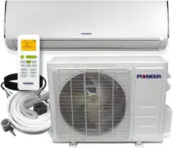
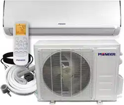
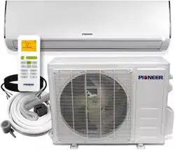
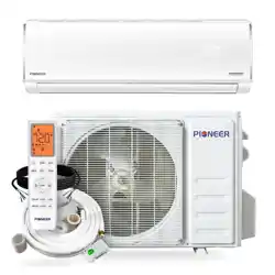
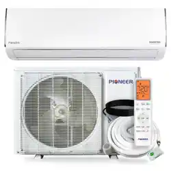
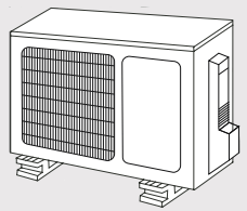
High Wall-Mounted Air Conditioner
The system is made up of two or more units connected together via insulated copper pipes and an electrical communication cable. The indoor unit is mounted onto one of the walls in the room that is to be conditioned. The outdoor unit is installed on the ground outside or on the wall of the dwelling using suitable mounting brackets.
| No. |
Description |
| 1 |
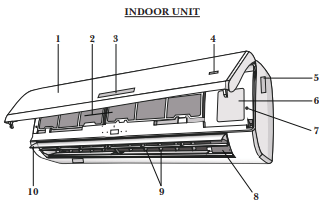
Front Panel |
| 2 |
Air Filters |
| 3 |
LED Display |
| 4 |
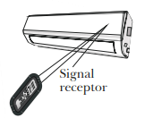
Signal Receiver |
| 5 |
Indoor Unit Rating Label |
| 6 |
Terminal Block Cover |
| 7 |
Emergency (Manual) Button |
| 8 |
Ionizer Generator (Optional) |
| 9 |
Deflectors |
| 10 |
Airflow Direction Louver |
| No. |
Description |
| 11 |
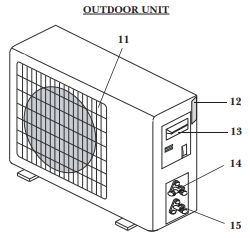
Air Outlet Grille |
| 12 |
Outdoor Unit Nameplate |
| 13 |
Terminal Block Cover |
| 14 |
Gas (Suction) Line Valve |
| 15 |
Liquid Line Valve |
Note: The illustrations above are only intended to be a simple diagram of the appliance, and may not fully correspond to the actual appearance of the system. Technical data is printed on the system’s labels.
Indoor Unit Overview
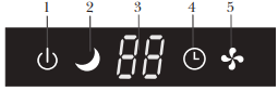
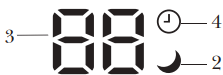
Front Panel Display
| No. |
LED Icon |
Symbol |
Description |
| 1 |
POWER |
 |
Indicates that the unit is currently powered on |
| 2 |
SLEEP |
 |
Indicates that the system is currently in SLEEP mode |
| 3 |
Temp. Display |
 |
Displays the current set temperature or any error codes |
| 4 |
TIMER |
 |
Indicates that the TIMER function has been set |
| 5 |
RUN |
 |
Indicates that the fan is currently on and running |
The shape and position of switches and indicators may vary according to the model, however the functions remain the same. There may be variances between the amount of digits that are shown on the remote (3) vs. the amount on the indoor unit (2).
Emergency Manual Button And Auto-Restart Function
The emergency button is located at the terminal block cover of the unit under the front panel.
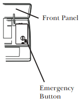
Emergency Manual Button
If the remote controller fails to operate the system, proceed as follows:
- Open and lift the front panel up at an angle to gain access to the emergency button.
- Press the manual button once to start the unit in COOL mode.
- Press the button again within 3 seconds to start the unit in HEAT mode.
- Press a 3rd time within 5 seconds to turn off the unit.
Auto-Restart Feature
- This appliance is programmed with an auto-restart function.
- In case of sudden power failure, the control module will remember the settings configured before power loss.
- When power is restored, the unit will restart automatically, and will be set to the previous settings, which were preserved with this memory function.
Operating Instructions
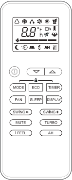
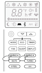
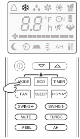
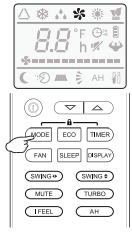
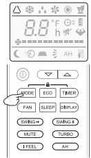
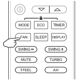
Remote Buttons Overview
| Button |
Description |
 |
Turns the air conditioner on or off |
 |
Decreases set temperature, set timing, or navigates the functional menu |
 |
Increases set temperature, set timing, or navigates the functional menu |
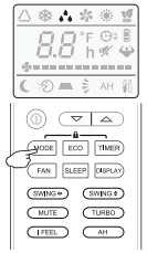
| MODE |
Selects the mode of operation (Auto, Cool, Dry, Fan, and Heat modes) |
| ECO |
Activates/deactivates the ECO feature |
| TURBO |
Activates/deactivates the TURBO feature, which allows the system to reach set temperatures quicker |
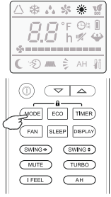
| FAN |
Configures the fan speed (Auto, Low, Mid, and High) |
| TIMER |
Configures the automatic on/off times |
| SLEEP |
Toggles the system’s Sleep Mode |
| DISPLAY |
Turns the LED display on or off |
| SWING |
Activates the swinging of the louver |
| MUTE |
Puts the system into silent mode |
| I FEEL |
Activates the system’s Follow Me mode |
| AH |
Controls the 46°F “Away from Home” freeze protection. |
The display and some features of the remote control may vary according to the model of the system.
The shape and positions of the buttons and indicators may vary according to the model of the system, but the features and functionality would remain the same.
The unit will confirm the successful reception of each button command with a beep
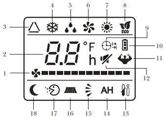
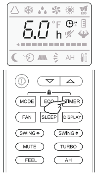
Remote Controller LED Screen and Icons
| No. |
Icon |
Description |
| 1 |
 |
Fan Speed |
| 2 |
 |
Temperature |
| 3 |
 |
Auto Mode |
| 4 |
 |
Cooling Mode |
| 5 |
 |
Dry Mode |
| 6 |
 |
Fan Only Mode |
| 7 |
 |
Heating Mode |
| 8 |
 |
ECO Mode |
| 9 |
 |
Timer |
| 10 |
 |
Battery |
| 11 |
 |
Turbo Mode |
| 12 |
 |
Mute Function |
| 13 |
 |
I Feel/Follow Me Mode |
| 14 |
 |
46°F Freeze Protection |
| 15 |
 |
Up-Down Auto Swing |
| 16 |
 |
Left-Right Auto Swing |
| 17 |
 |
Health Function |
| 18 |
 |
Health Function |
NOTE ON ILLUSTRATIONS
The illustrations in this manual are strictly for explanatory purposes. The actual display and some functions of the remote controller may vary according to the model purchased.
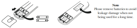
Replacement of Batteries
Remove the battery cover from the rear of the remote controller, by sliding it downward in the direction of the arrow as depicted below. Install batteries according to the depicted directions (+ and -) as shown on the remote controller. The cover then slides back into place.
Use 2x AAA batteries. Do not use re-chargeable batteries. Replace old batteries with new ones of the same type when the display is no longer legible. Do not dispose of batteries as unsorted municipal waste. Disposal of such waste separately for special treatment is necessary. If the system will not be used for a long time, remove batteries to prevent leakage.
Configuring Remote Controller Settings (some models)
Depending on the system, the control type (Cooling Only or Heat Pump) must be set after a battery swap is done. As soon as the batteries are inserted, the symbols and will begin flashing. Operate as below:
- When the symbol is displayed, push any button to set the control type to Cooling Only.
- When the symbol is displayed, push any button to set the control type to Heat Pump.
Note: If the remote control is used to set the control type to Cooling Only, the heating function cannot be activated in systems with a heat pump. To modify or reset this setting, first remove the batteries and then reinstall and repeat.
The temperature display can be set to show degrees in either °C or °F by doing the following:
1. Press and hold the TURBO button for 5+ seconds to activate the change prompt.
2. Repeat this process once more to switch between °C and °F options.
3. Release the button, and the setting will be active after 5 seconds have elapsed.
Operating the Remote Controller Successfully and Safely
- Ensure no objects come between the remote controller and signal receptor of indoor unit.
- Keep the remote at least 3 ft away from televisions and other electrical appliances.
- Always direct the remote controller toward the air conditioner.
- Don’t leave the remote exposed to sunrays.
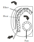
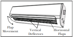
Regarding the Airflow of the Indoor Unit
The air that is pulled in by the fan (the “return air”) enters the grille and is passed through the filter. It is then cooled/dehumidified/heated through the heat exchanger.
The direction of the air output is manipulated up and down by the motorized louver, and left to right via manually controlled vertical deflectors. Some models may come with “dual-swing” capability, which offers both a horizontal and vertical motorized air flow swing.
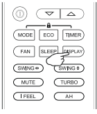
Controlling the System’s Airflow
1. Pressing the SWING buttons activate the louver.
- Press the
 button to trigger the horizontal flaps to swing up and down. Press this button again to stop swing movement at the current angle.
- Press the
 button to trigger the vertical flaps to swing left and right. Press this button again to stop swing movement at the current angle.
2. If the vertical deflectors (which are located underneath the flaps) are adjusted manually, they can be used to fix the airflow in a certain vertical position before turning the system on.
CAUTION
- Do not manipulate the louvers themselves manually, or serious damage may occur.
- Deflector adjustments should be made only when the system is switched off.
- Never poke fingers, sticks, or other objects into the air inlet/outlet vents.
COOLING Mode
Cooling mode allows the air conditioner to cool the room while also reducing the humidity of the air in the room.
To put the system into cooling mode, press the  button until the symbol appears on the remote’s display.
The and buttons can then be used to set a temperature lower than that of the room.
HEATING Mode
Heating mode allows the air conditioner to heat the room.
To put the system into heating mode, press the button until the symbol appears on the remote’s display.
The and buttons can then be used to set a temperature higher than that of the room.
NOTE
- In heating mode, the appliance will periodically enter a defrost cycle, which is essential in order to clean frosting off the condenser and recover heat exchange capability. This process is normal and lasts for 2-10 minutes.
- During defrosting, the indoor unit’s fan will cease operation. After the cycle is completed, the system will resume its normal heat mode operation automatically
DRY Mode
Dry mode is a limited function that can help reduce the humidity/moisture of the room.
To put the system into dry mode, press the button until the  symbol appears on the remote’s display.
An automatic preset of this mode is then activated.
FAN-ONLY Mode
Fan-only mode is used to set the system to use only air ventilation and no heating or cooling.
To put the system into fan-only mode, press the button until the symbol appears on the remote’s display.
AUTO Mode
- Auto mode will let the system determine the running configuration based on the set temperature and the current room temperature.
- To put the system into AUTO mode, press the button until the
 symbol appears on the remote’s display
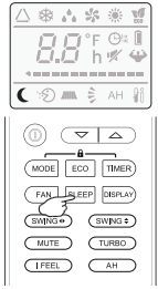
Turning the Display On or Off
The LED display on the front panel of the system can be turned on or off as desired.
To do so, press the  button in order to switch off the LED display on the front panel. This button can be pressed again to turn the LED display back on.
SLEEP Mode
Sleep mode is generally meant for periods of lower cooling requirements, such as during typical sleeping hours. This mode will result in decreased energy use, and can only be activated via remote control.
After 10 hours in sleep mode, the air conditioner will revert to the previously set mode.
To put the system into sleep mode, press the  button, and the
  symbol will appear on the display. Press this button again to exit from this mode.
Changing the Fan Speed
The fan speed can be changed between AUTO, LOW, MID, and HIGH speeds.
To do so, press the  button. The running fan speed can then be set.
Using the Timer - TIMER ON
The TIMER feature allows you to set a time delay for the system to turn itself on or off.
To set a time delay for the system to turn itself on in X number of hours:
1. Begin by pressing the  button while the system is powered off. The symbol will then display. You can then set the needed modes.
2. Set the desired mode (COOL, HEAT, AUTO, FAN, DRY) by pressing the button.
3. Set the desired fan speed with the button.
4. Use the and buttons to set the desired operation temperature.
5. Press the button again to set the switch-on time. Use the and buttons to set the needed time delay.
6. Press the button again to confirm. It can also be pressed once more to cancel the setting.
Using the Timer - TIMER OF
The TIMER OFF feature allows the appliance to turn itself off after X number of hours have passed. The symbol will appear. To set a time delay for the system to turn itself off in X number of hours:
1. Confirm that the appliance is on and running.
2. Press the button to enter the prompt for switching off the system. Use the and buttons to configure the time delay setting.
3. Press the button again to confirm. It can also be pressed once more to cancel the setting.

Maintenance of the Air Conditioner
Periodic Maintenance Is Essential for The System!
Maintaining the air conditioner will ensure that is stays efficient. Before carrying out any sort of maintenance, always ensure that the power supply to the system is turned off.
Indoor Unit
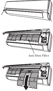
Anti-Dust Filters (Clean once every 2 weeks)
1. Open the front panel by pulling outward and upward at the indicated location.
2. Keep the front panel raised with one hand and take out the air filters with the other.
3. The filters are washable and should be cleaned with warm water (under 113°F).
4. Leave the filters to dry in a cool, dry place.
5. Keeping the front panel raised with one hand, insert the air filters with the other.
6. Close the front panel.
Any electrostatic or deodorizing filters, if installed, are not washable and should be replaced once every 6 months.
Interior of the Indoor Air Handler
In addition to the filters, the interior of the indoor unit itself as well as the inner coil should be inspected every season. The front panel can be disconnected and removed from the top hinge where the pegs connect. This will allow for easier inspection of the interior and behind the air filters. The interior should be cleaned with damp cloth and neutral soaps. Do not use any sort of aggressive solvents or detergents. Only a soft cloth that is lightly damp should be used.
Indoor Unit Installation Instructions
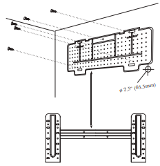
Installation of the Mounting Plate
1. Place the included mounting plate against the wall where the system will hang that fulfills the constraints on Page 22. Use a level to ensure that the plate is horizontally level.
2. Drill 1.3” deep holes for each screw to enter, the locations are flexible but should be spaced well.
3. Insert the plastic anchors into each of the holes.
4. Fix the mounting plate to the wall by using the included tapping screws. Check that it is secured.
Note: The actual appearance of the mounting plate may differ slightly but the process is similar.
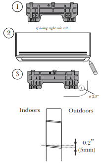
Drilling the Wall Hole for Piping
CHECK PAGES 43-44 FOR MOUNTING HOLE GUIDELINES ACCORDING TO THE BRACKET.
1. With the mounting plate firmly affixed to the wall, mount the indoor unit onto the mounting plate temporarily in order to determine the location of the wall hole in the next steps.
2. Using a pencil, lightly trace the bottom corner of the indoor unit, depending on which side exit the piping will go through (see Page 26).
3. Take the inside unit off of the plate, and make a mark of where the hole will be (PG. 43-44), to ensure ample clearance between the tracing and bracket.
4. Drill a 2.5” wall hole at a slight downward angle using a core drill, being careful to avoid wires, plumbing, and other sensitive materials. The bottom of the inside hole should be ~1/4” above the bottom of the outside hole.
Connecting the Refrigerant Piping to the Indoor Unit
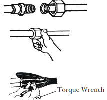
Once the copper piping kit coil is unwound, refer to the below instructions to proceed:
1. Bring the ends of both the copper line and the indoor unit line together. Align the centers of the pipes that will be connected.
2. Remove the indoor unit piping cap, and check that no debris is inside. Some gas may be heard escaping, it is just nitrogen.
3. Use any leak guard or leak sealant on the flares of the piping if available. Attach the flare nut and tighten as much as possible by hand. Torque correctly to the specifications found in the table below using two wrenches. Repeat the process for the other copper line.
TIGHTENING TORQUE FOR PROTECTION CAPS AND FLANGE CONNECTION
| PIPE |
TIGHTENING TORQUE [N x m] |
CORRESPONDING STRESS
(using a 20 cm wrench)
|
|
1/4” (Ø 6.35)
|
15 - 20 |
Wrist Strength |
| 3/8” (Ø 9.52 |
31 - 35 |
Arm Strength |
| 1/2” (Ø 12.7) |
35 - 45 |
Arm Strength |
| 5/8” (Ø 16) |
75 - 80 |
Arm Strength |
| TIGHTENING TORQUE [N x m] |
| Service Port Nu |
7 - 9 |
| Protection Caps |
25 - 30 |
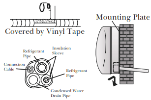
Wrapping the Lines and Mounting the Indoor Unit
For mounting the indoor unit, proceed as follows:
1. Arrange the pipes, cables, and drain hose well.
2. Lag the pipe joints with insulation material, and secure with vinyl tape as depicted in the figure.
3. Run the bound bundle through the wall hole, and mount the indoor unit securely onto the mounting plate. Press/push the lower part of the indoor unit so it clicks onto the mounting plate.
Outdoor Unit Installation Instructions
Outdoor Unit Installation Location Selection
Follow the below best practices for selecting an optimal space for installation the indoor unit:
- DO NOT install the unit near sources of heat, steam, or flammable gases.
- DO NOT install the system in areas prone to extreme winds or dust.
- DO NOT install the outdoor unit in an area that has many passersby.
- DO NOT select a location where the air discharge and operating sound level will disturb others.
- DO install the system in a shaded area or utilize a cover/sun protection that will not interfere with air flow. This will also protect the system from rain or snow.
- DO install the unit in a safe and sturdy location.
- DO install rubber vibration absorbers if the system will be subject to vibrations.
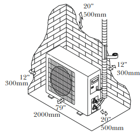
- DO obey the following tolerances depicted in the illustration below to ensure air flow:
Minimum Required Installation Space
SPECIAL CONSIDERATIONS FOR EXTREME WEATHER CONDITIONS
If the unit is exposed to heavy wind:
Install unit so that air outlet fan is at a 90° angle to the direction of the wind.
If needed, build a barrier in front of the unit to protect it from extremely heavy winds.
If the unit is frequently exposed to heavy rain or snow: Build a shelter above the unit to protect it from the rain or snow. Be careful not to obstruct air flow around the unit. If the unit is frequently exposed to salty air (seaside air): Use specifically approved anti-corrosion coating sprays onto the heat exchanger surface in order to resist corrosion.
Mounting the Outdoor Unit to the Selected Location
The outdoor unit should be installed either on a pad or on a solid wall and fastened securely. Follow the procedure below before connecting any pipes or cables:
- Decide what the best position on the wall or on the ground is, and leave enough space to be able to carry out maintenance easily. Anchoring dimensions are provided on Page 42.
- If wall mounting, fasten the support brackets to the wall using hardware that is particularly suited for the type of wall. Use the appropriate amount of hardware for the application.
- The unit must be installed following all national regulations.
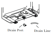
Outdoor Unit Condensate Water Drainage
The condensate water and the ice formed in the outdoor unit during heat mode can be directed away using the optional drain line included with the system.
1. Fasten the drain port in the 1-inch port located in the part of the unit depicted in the diagram.
2. Connect the drain port and the drain line.
3. Ensure the condensate will drain to a suitable place.
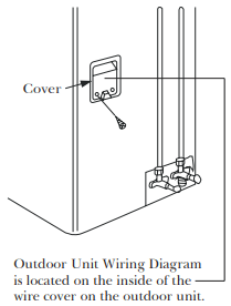
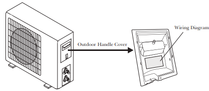
Power/Signal Electrical Wiring to the Outdoor Unit
On the outdoor unit, the wiring diagram is located in the inner side of the handle cover.
The outside unit’s terminal block is protected by an electrical wiring cover on the side of the unit. A comprehensive wiring diagram is printed on the inside of the wiring cover.
1. Unscrew and remove the handle on the right side plate of the outdoor unit.
2. Wire the system using the appropriate gauge wire found on page 28/32 and the wiring diagram found on the handle cover. See page 44 for more details.
3. Fasten the power connection wires into place using the supplied wire clamps.
4. Check the wiring against the diagram to ensure it is wired correctly. A proper ground must be established.
5. Re-screw and reinstall the cover handle.
Troubleshooting
| MALFUNCTION |
POSSIBLE CAUSES |
| If the appliance does not operate or respond... |
There is a power failure/plug pulled out
The indoor/outdoor unit fan motor was damaged
There is a faulty compressor or thermomagnetic circuit breaker
There is a faulty protective device or fuses
The electrical connections are loose
The system has entered a protection mode
The system has entered an overvoltage or undervoltage protection
The TIMER-ON function is active
The electronic control board was damaged
|
| If there are strange odors... |
The air filter is dirty |
| If there’s running water... |
If there’s running water... |
| If a fine mist is coming from the air outlet... |
This occurs when the air in the room becomes very cold, for example in “COOLING” or “DEHUMIDIFICATION/DRY” modes |
| If strange noises are being emitted... |
This noise is made by the expansion or contraction of the front panel due to variations in temperature, and if so, is normal |
| If the airflow is insufficient, and the air is not hot or cold enough... |
The temperature setting is unsuitable
The air conditioner intakes and outlets may be obstructed
The air filter may be dirty
The fan speed may be set at the minimum
There may be too many other heat sources in the room
The system may be getting low on refrigerant, pressures should be checked
|
| If the appliance does not respond to commands... |
The remote control may not be close enough to the indoor unit
The batteries of remote control may need to be replaced
There are obstacles between remote control and indoor unit signal receiver
The DISPLAY button has been pressed
|
| If the display is off... |
The DISPLAY button has been pressed
There has been a power failure
|
| Switch off the air conditioner immediately and cut off the power supply in the event of... |
Strange noises not due to expansion/contraction are heard during operation
The electronic control board is faulty or malfunctioning
Any fuses or switches are faulty or malfunctioning
The sound of spraying water or objects are heard inside the appliance
The cables or plugs have overheated
There are very strong odors being emitted from the appliance
|
ERROR SIGNALS ON THE DISPLAY
In case of error, the display on the indoor unit may show the following error codes:
| Display |
Description of the error |
 |
Indoor temperature sensor fault |
 |
Indoor pipe temperature sensor fault |
 |
Outdoor pipe temperature sensor fault |
 |
Refrigerant system leakage or fault |
 |
Malfunction of indoor fan motor |
 |
Outdoor air temperature sensor fault |
 |
Outdoor discharge temperature sensor fault |
 |
Outdoor IPM module fault |
 |
Outdoor current detection fault |
 |
Outdoor PCB EEPROM fault |
 |
Outdoor fan motor fault |
 |
Outdoor suction temperature sensor fault |