
1
Pipe Inspection Camera
Operation Manual
Read thisOperation Manual carefully before using this tool

2
Contents
INTRODUCTION ................................................................................................3
General Safety Rules......................................................................................................... 3
Application........................................................................................................................ 3
PRODUCT OVERVIEW...................................................................................3
Camera Head.................................................................................................................... 4
Cable & Reel ..................................................................................................................... 4
Toolbox Unit...................................................................................................................... 5
Function Buttons & Joystick.............................................................................................. 5
Main Button Operation.................................................................................................. 6-8
Package Contents............................................................................................................. 8
SPECIFICATIONS......................................................................................9-10
INSTALLATIONS..........................................................................................11
1. Install Cable&Reel (fg. 6) ............................................................................................11
2. Install Toolbox (fig. 7)...................................................................................................11
3. Instal l Camera Head (fg. 8) ..........................................................................................12
4. Keyboard Scanning........................................................................................................12
FUNCTION GUIDE & OPERATING INSTRUCTIONS........................................13
Touch Screen Icon Introduction .............................................................................13-14
DVR Operation ........................................................................................................15-16
1. Insert the card.........................................................................................................15
2. Turn On/Off..............................................................................................................15
3. Button Functions.....................................................................................................15
4. Parameter Settings..............................................................................................15-16
5. File Management.....................................................................................................16
6. APP Settings.............................................................................................................17
7. APP Monitoring Settings...........................................................................................18
TEXT WRITER OPERATION..........................................................................19
Text Input .....................................................................................................................19
METER COUNTER OPERATION....................................................................19
PUSH CABLE & CAMERA OPERATION..........................................................20
At the Job Site..........................................................................................................20-21
Retrieving the Push Cable...........................................................................................21
BATTERY SAFETY & USE GUIDE...................................................................22
Using Safety ...................................................................................................................22
Using Guide...................................................................................................................22
OTHERS.....................................................................................................23
Troubleshooting...........................................................................................................23
Camera heads options..............................................................................25

3
INTRODUCTION
The pipe inspection system is a powerful set of tools that helps you locate and diagnose
problems in a pipeline system.
The system is widely used in inspections of sewer, central air conditioning, chimney,
plumbing, building, cable pipe and pipe ventilation systems and other places.
GENERAL SAFETY RULES
Precautions
Read all safety warnings and instructions. Failure to follow warnings and instructions may
result in electric shock, fire and/or serious injury.
1. Save this operation manual for future reference.
2. Do not operate this device in explosive atmospheres, such as in the presence of flammable
liquids, gases, hazardous chemicals,
superheated liquid or heavy dust. It may create sparks which may
ignite the dust or fumes.
3. The camera head ,the push cableand toolboxare waterproof (when camera installed on rod
cable).
Do not expose them to water or rain when all connectors areexposedwithoutwaterproofslot.
This will increase the risk of electrical shock.
4. Avoid using the device in environments of extreme cold, heat or humidity as it may damage
the device.
5. Do not drop or press hard on the device.
6.Thisdevice supports videorecording viaU-disk or videostorage ona SDcard.Alwaysbackup your
databeforeinsertingyour SDmemory card tothissystem.The manufacturer isnot responsiblefor
any datalossordamage onyourSDmemorycard foranyreason.
7.Donot disconnect theunitwhile recordingorplayingback.Itmaydamage the unitand/ortheSD
memorycard.
8. Service or maintenance performed by unqualified person could result in injury.
9. Do not use this device in places where there is high voltage equipment. It doesn’t contain high
voltage protection and isolation.
Application
Ability to go through 90° bendsinpipe DN45mm(for 23mmcamera with7.0mm rod)and in pipe
DN52mm-200mm(for 23mmcamera with 7.5mmrod) ;andinpipe DN32mm(for14mmcamera
with4.8mmrod).
PRODUCT OVERVIEW
The pipe inspection system includes the following three main parts: Camera
H
ead, CableWheel
with Reel,Toolbox Unit (including all-in-one DVRmonitor, keyboard).
The camera head is equipped with built-in high-brightness LEDlights, a scratch-resistant sapphire
lens cover. 316L stainless steel housing allow the camera to withstand repeated hits in various
pipes.The HDR image sensor expands the camera’s dynamic range, allowing to view more
clear when in dark or bright pipes, e.g. stainless steel pipes.
Flexible stainless steel spring and associated components make the camera head possible to go
through bend pipes.13.3inch touch screen monitor can record video, take photos,flipand zoom,
wirelesstransmitvia APP.The rain-proof structure is easier toclean.
4
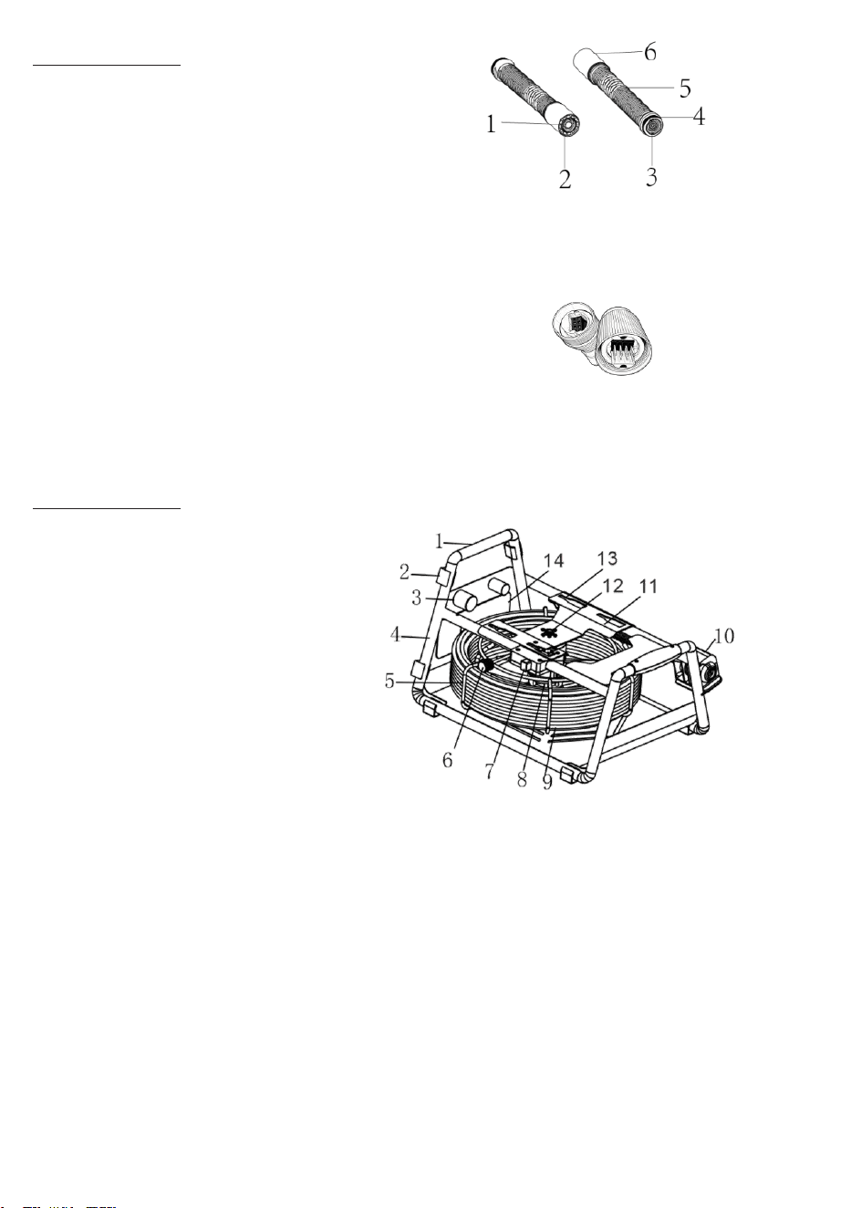
Camera Head
1.Sapphire Lens
2.LED
3.Gold Connecter/Newhalf-moonConnector
4.Camera O-ring
5.Stainless Steel Spring
6.316L Stainless Steel Case
Cable & Reel
1.SoftHandle
2.Foot Pad
3.Camera Skid Holder
4.Cable Frame
5.Coil Reel
6.Cable Brake
7.ReleaseToolbox button
8.MeterCounter
9. Push-rod Cable
10.Camera Holder
11.Toolbox Fixed Seat
12.Cable Connector to Camera
13.CableGuide
14.Label
New half-moon connector :
5
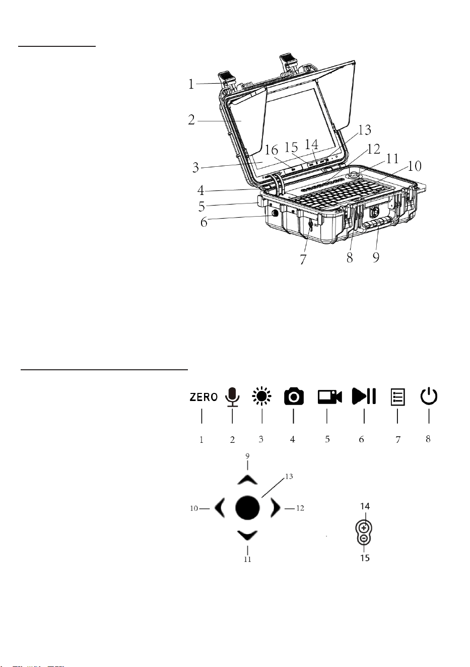
Toolbox Unit
1.Toolboxlock
2.Sunshade
3.13.3inch TouchScreenDisplay
4.DataCable
5.CableClip
6.AviationConnector
7.DC Input
8.KeyboardBuckle
9.Handle
10.Keyboard
11. Joystick
12. FunctionButtons
13.DC5VType-C
14.MicroSDcard
15.HDMIVideoout
16.USBDisk
Function Buttons & Joystick
1.Meter Counter Zero-set
2.Microphone On/Off
3.LED Brightness
4.PhotoShoot
5.Start/End Video
6.Playback/Pause Video
7.Main Menu/Return
8.ON/OFF
9.Upward(Nearfocus+)
10.Left
11.Downward (Far focus -)
12.Right
13.Confirm /Enterfocus adjustmode
14.Nearfocus/15.Farfocus
Figure 3.
Toolbox Unit
6
Main Button operation
7
Main Button operation
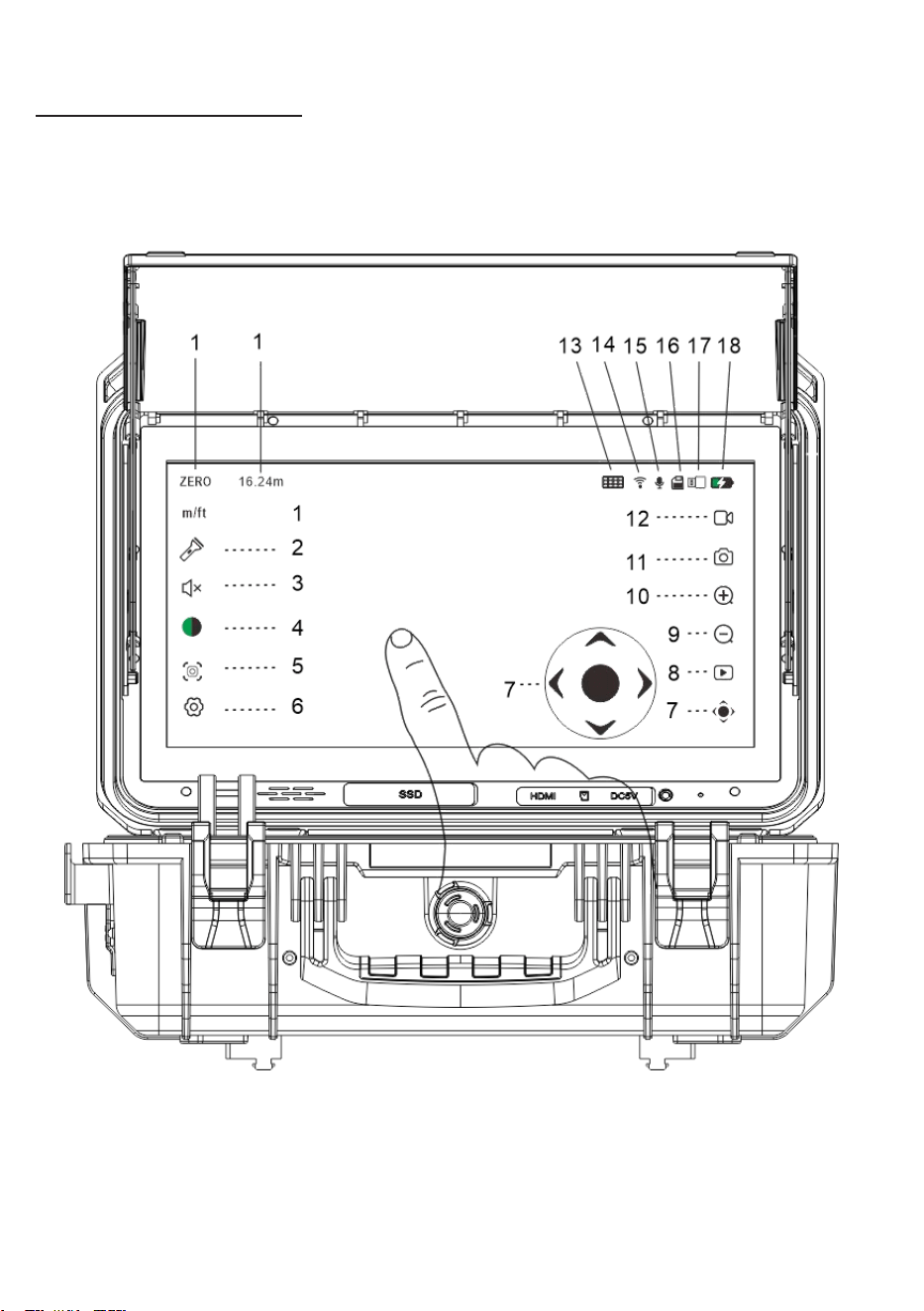
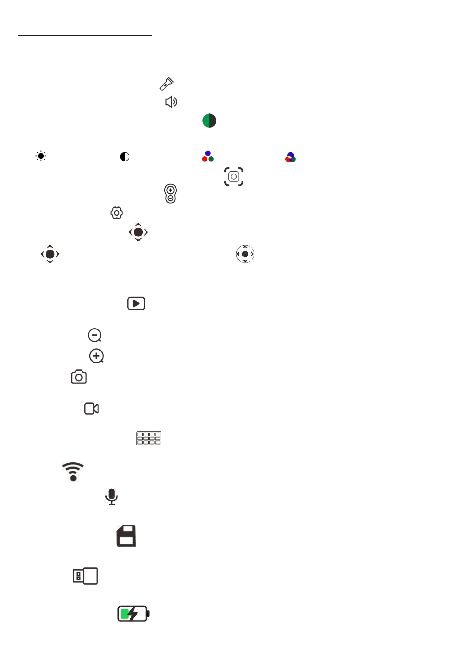
1. ZERO:
Clear the current distance and recalculate it.
m/ft:Switch between meter/feet.
2 .LED Brightness Control : Move the slider to control cam’s LED brightness.
3.Speaker Volume Control : Move the slider to control the speaker volume.
4. Display Parameter Adjustment
:Move the sliding block to adjust the
parameter.
:Brightness :Contrast :Colourity :Saturation
5. .Joystick manual focus adjustment
Touch this to enter into focus adjustment.
6. System Setup :
Touch this to enter into system setup.
7. Pan Tilt Control : Enter and exit gimbal control. This is only for PTZ camera.
Click ,pop up the pan tilt control interface ,touch the up, down, left, and right
icons to control it.
8. Playback/Return : Press it to enter review photos and videos. Press Up-Down-
Left-Right to select.
9. Zoom out : Touch this to zoom out the screen.
10. Zoom in
:Touch this to zoom in the screen.
11.Photo : Press briefly, flashes once and get a photo.
12. Record :
Press to record, and the icon turns blue.The video timer can time. Press
again to end.
13.Keyboard for Text : Click it, the keyboard pup up.
14. WiFi :WiFi is on; if crossed, WiFi is off.
15.Microphone : Microphone is on. If crossed, Microphone is off.
16. Micro SD card : Card is Okay. If crossed, abnormal or no card.
17.U-disk :U-disk is okay. if crossed, abnormal or no U-disk.
18.Battery power :Display battery power, the lighting shows it’s charging.
8
Package Contents
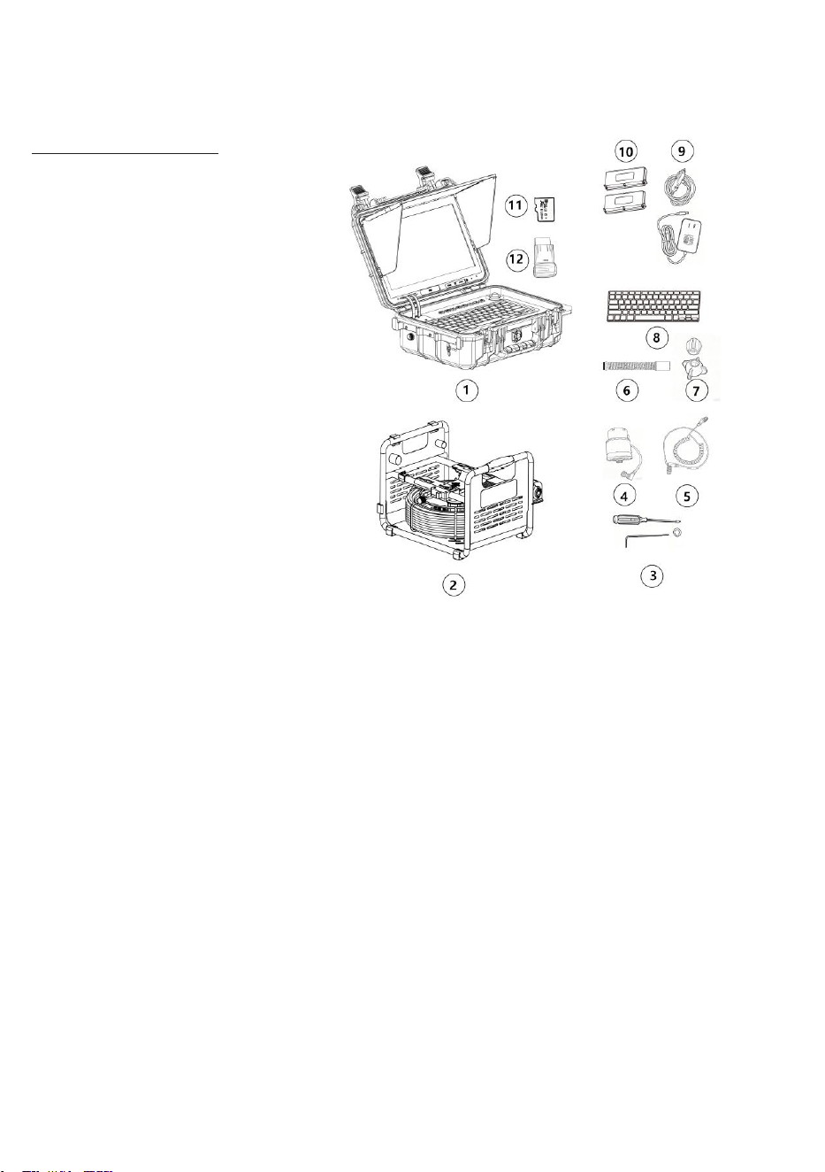
1.
Toolb ox
with DVR
2. FrameCableReelwithCable
3.Spanner/Screw +O-ring
4.Meter Counter
5. Connects Cables
6.23mmCamera
7. 1x43mm Skid,1*80mm Skid
8 Keyboard
9. Adapter/Car Charger
10.
B
attery Pack*2
11. Micro SD Card
12. U-disk
2592 x 1944

9
SPECIFICATIONS
Type
Item
3 in 1 Connetor Cameras Parameter
Camera
Diameter of
camera
Φ35mmPT camera
Φ23mm camera
Φ32mm camera
Resolution
AHD 2592*1944
AHD 2560*1920
AHD 2560*1920
View Angle
120°(diagonal)
120°(diagonal)
120°(diagonal)
Depth Of Field
5-100cm(adjust )
3-12cm(approx )
8-30cm(approx )
Camera Size
Φ35mm×82.5mm
(Main body )
Φ23mm×42mm
(Main body )
Φ32mmx51mm
(Main body )
Camera Length
216 mm
177mm
184mm
Front Lens/
Shell material
Sapphire
304#Stainless
Steel
Sapphire
316#Stainless
Steel
Sapphire
316#Stainless Steel
Lighting
Built-in 6×White
LED
Built-in
12×White LED
Built-in 6× White
LED
Sonde
Frequencies
512hz
512Hz
512Hz
Auto Upright
/
self - leveling
design
self - leveling
design
Water -Proof
30m water
(Camera fix on
Cable)
30m water
(Camera fix on
Cable)
30m water
(Camera fix on
Cable)
DVR
Screen
Resolution
1920*1080 LCD (13.3” )
Image
Support Image Flip
Video Resolution
AHD 4K/2K/1080P / 720P
Video Encoding
High Compression / H.264
Photograph
Resolution
32MP, 16MP, 8MP,4MP, 2MP
Audio Recording
Support Local Sound
External Memory
Micro SD Memory Card/USB Disk up to 1TB,default 128GB or
USB-disk with 128GB
LED Driver
Built-in Dimmer
Main Function
Focus Adjustment/Video/Photo/Playback/10*zoom /flip/
WiFi
Language
Simplified Chinese, English, Traditional Chinese, Korean,
Russian, German, French, Ukrainian etc.
Audio
input/output
1.0Vp-p (20Hz-20KHz)
WiFi
Transmission
WiFi Protocol 802.11 a/b,WiFi Channel 5.0Ghz,
WiFi power <16dBm

10
APP
Inspection SYS App for monitoring, photo/recording,
zoom,sharing;
Video Output
HDMI 1080P
Power
Supply&Currency
DC 12V 5A
Battery Capacity
6500mAh Li-on Battery*2
A Single Charge
Work Time
10 hours
Charge Time
About 5-6 hours
Keyboard
Typing Language
English
page
1 Page
Characters per
page
500
Hide Characters
Quick One Key hiding
Keyboard
Compatibility
Specific PC keyboard
Cable
Reel
Meter counter
Removable and waterproof
Cable coil
Easy to removable and exchange
Precision of Meter
±(10cm + 0.5%) max
Cable Diameter
Φ5.0mm
Φ7.0mm/Φ7.5mm
Cable Length(m/ft)
20/ 30/ 40 meter
(Optional)66/99/132ft
20/ 30/ 40 meter (Optional)66/99/132ft
Tool Box
Waterproof rate
IP68
Size
380×260×150mm(L×W×H)
Box color
Black
General
Storage/Operation
Temperature
-20~60°C/+4~+140°F
MEAS.
53×50×40cm (LxW xH)
Weight
21 Kg(Approx )
11
INSTALLATION
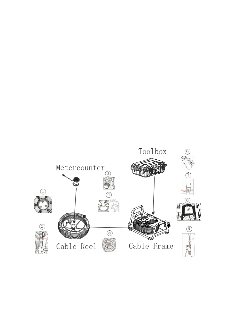
To reduce the risk of serious injury during use, follow these procedures for proper assembly.
①Putthe meter counter into the coil reel with three screws.
② Connectthe connectoron the coil reel.
③
Insertthe cablereel from the brake side (brake must be released) into theframe.
④Pull out some wirethrough the guide hole and mount the camera onto its holder.
⑤Push upward to align the cable reel withthe four screw holes aroundthe frame's connector,
then tighten the screws.
⑥
Connect the spring wire female connector on the frame.
⑦ Secure the connection wire into the connection wire slot.
⑧
Push the toolbox into its fixed seaton the frame until it locks automatically. Takeoff the
toolbox just needto press the release button.
⑨Connect the spring wire male connector on the toolbox.The adustthe length and fixed it on
the wire clip.
Figure 5.
Installation of the cable reel and toolbox
12
3.Install Camera Head
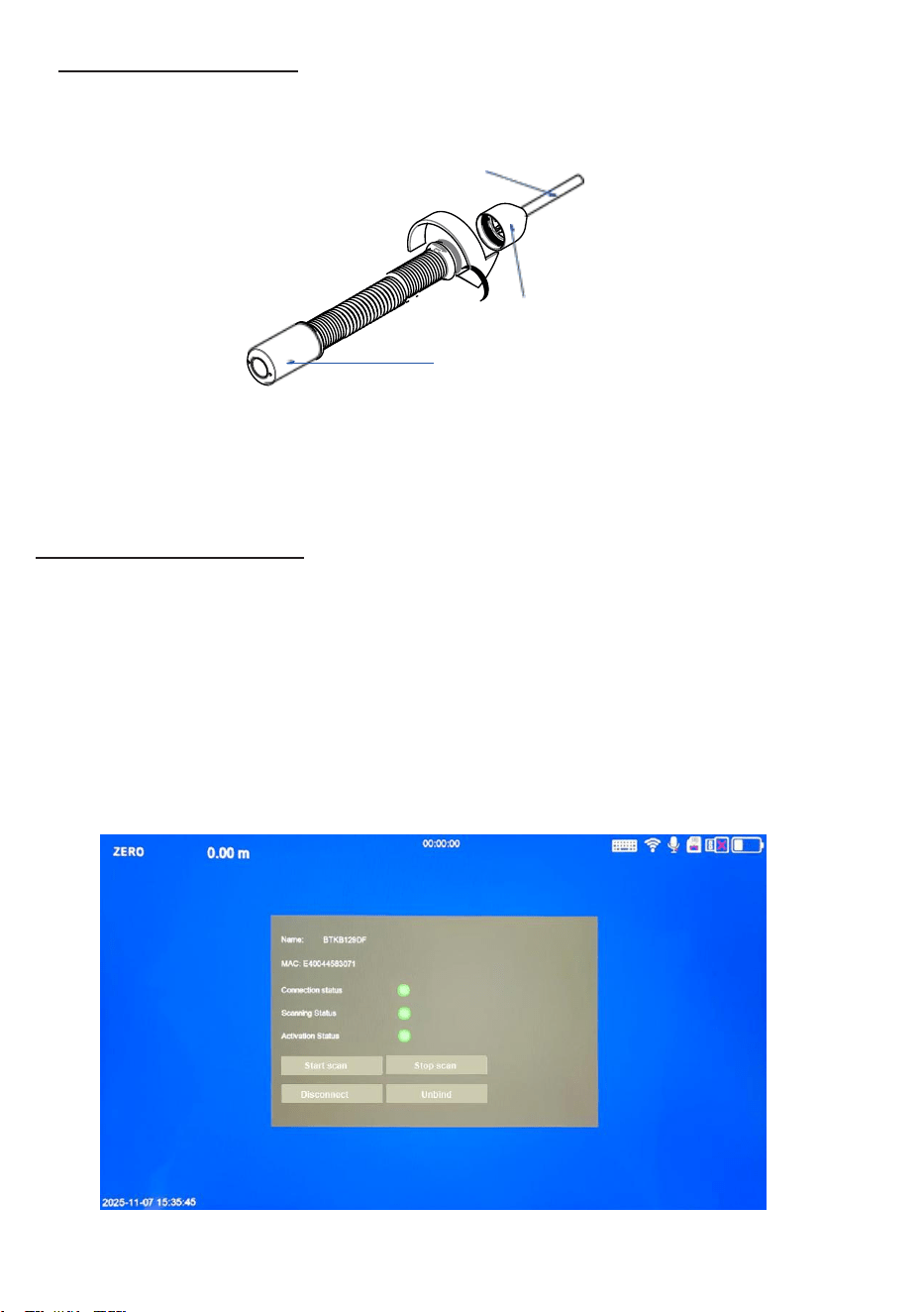
Hold the cable connector in one hand, then screw the camera and fix it on the cable tightly.
Cable
Camera Connector
Camera Head
Figure 6. Install Camera Head
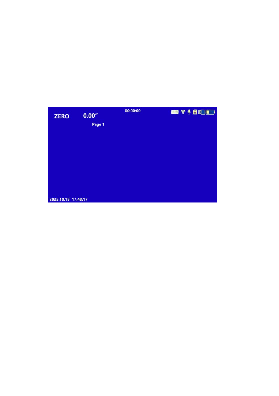
4. Keyboard Scanning
Turnon ON/OFFswitch onthe backof the keyboard.
Click the icon ofkeyboardonthescreen. Thenclickthe Start scanto match the KB.
Thenpress theFn+1 key 3 seconds toenter below interface.
Makesure the Connectionstatusisgreen.
The nameof the KBwillshow onthe right top.
Click the nameofthe KB, you willget the Nameand MAC.
Ifchange KB,youhaveto Unbind the KB firstand Disconnect it.
(Note: the KBrequires2 pcs 7#AAA batteries.)
13
TEXT WRITER OPERATION
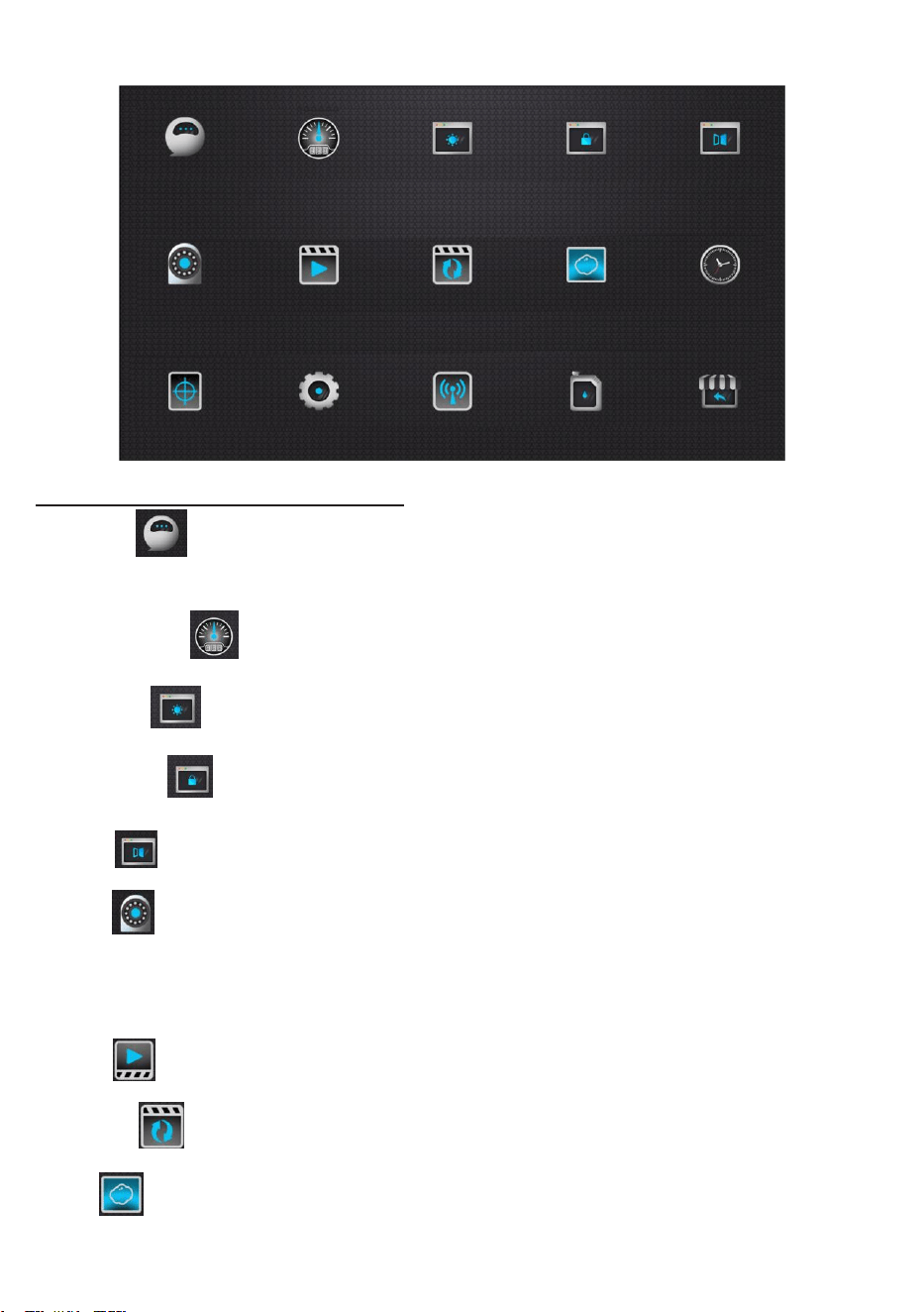
The keyboard text writer is used to type characters with the keyboard and display on
screen. The characters can be displayed in recorded video or captured photo.
Text Input
1. Clickthe Esc to start/Hide text input.
2. Typing characters with keyboard.
Back
space key to delete ,andEnter key to change a new
line. Click photo/video icon to save present page to DVR memory.
3. Ctrl+Del key to delete all characters in present page.
You can type and edit characters while recording, the typing and editing will be recorded in the
video files.
Figure 15.Text Input
14
FUNCTION GUIDE AND OPERATING INSTRUCTIONS
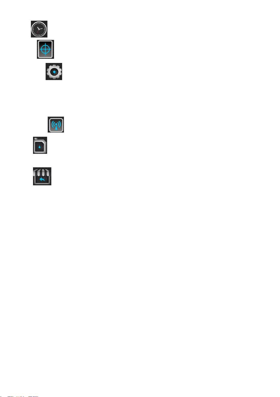
Touch Screen Icon Introduction:
Language :Show the available languages: English, Chinese, Traditional Chinese,
Japanese, Korean,German,Russian,Dutch,French
Meter Counter : show push rod cable distance
Brightness :Touch to set the screen brightness.
Screensaver :Touch to set the time of screen Saver
Mirror :Touch to set: normal display; flip horizontal; flip vertical; flip horizontal &vertical.
Camera : Touch to set camera input resolution. According to the resolution & frame rate
of the known AHD camera, you can choose: 2K, 1080P, 720P, CVBS. Monitor will reset after
switching the resolution.
Record :Touch to set resolution of recording.
Loop Time : Touch to set the time of recycle recording: 1s, 5s, 10s, 20s, 30s.
Photo : Touch to set the size of photo: 32 mega pixels, 16 mega pixels,8 mega pixels,
4 mega pixels,2 mega pixels.
15
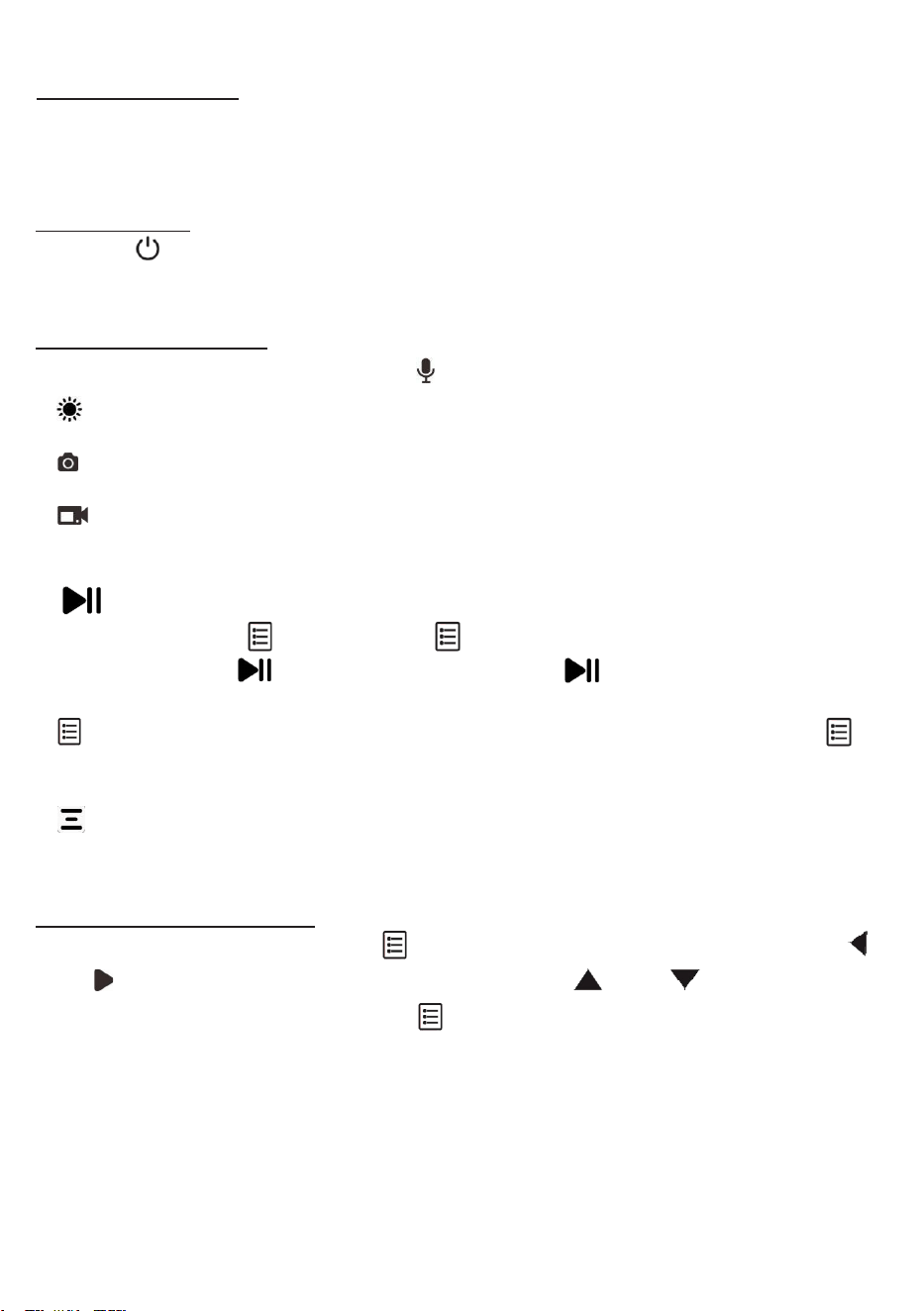
Clock :Touch to set the system date & time.
Reticle :Touch to set the types of baseline: off; cross; ruler; roundel.
Device Info :Touch to enter “Unit” and “Reset”. Touch “ Unit” to show device
information: WiFi name and password, memory size & remain storage of micro SD card,
firmware version. Touch “Reset” to delete all the settings in the current tablet monitor, and it
will be restored to its original factory state and restarted.
WiFi Switch : Touch to switch WiFi on or off.
Format :Touch and check format micro SD card. Format will delete all the data in micro
SD card. Be sure to do a good job of data backup.
Return : Touch it to return and exit system setting.
16
DVR Operation
1. Insert the card
Please insert the SD card before using the device. (Hint: In order to ensure the normal
operation of the device, please use a Class10 high-speed branded SD card. Please format the
SD card for the first time using it)
2.Turn On/Off
Press the [ ] key to turn on/off, and it will automatically enter the real-time image mode
when it is turned off.
3.Function Buttons
ZERO: Pressit toset metercounter tozero; Mic: Mic. is on. If crossed, Mic. is off.
LED control: Press it to select On-7 brightness cycle-OFF.
Photo : Press briefly, flashes once and get a photo.
Record: Press to record, and the icon turns blue.The video timer can time. Press again
to end.
Playback/Return: Press it to enter review photos and videos. Press Up-Down-Left-
Right to select. Press to confirm. Press Play again to exit;
When record, press to pause and stop timing; press again to restore.
Menu/Confirm: Press it briefly to enter. Press Up-Down-Left-Right to select. Press
to confirm.
Enter : Press to confirm and enter.
4. Parameters Settings
Under real-time image mode, press [ ] to enter the parameter setting; press joystick [ ]
and [ ] to select the menu you need to change, press [ ] and [ ] to select the sub-
menu that you need to change, and press [ ] to confirm the sub-menu you need to change;
4.1 Recording settings
Camera Head: To select the correct camera head type.
Loop recording: 1 min/ 5min /10min/ 20min/30min, the recorded files are divided
according to the set size, and the system will automatically prompt on screen when the
card is full.
Sound switch: you can turn on or off the recording sound.

17
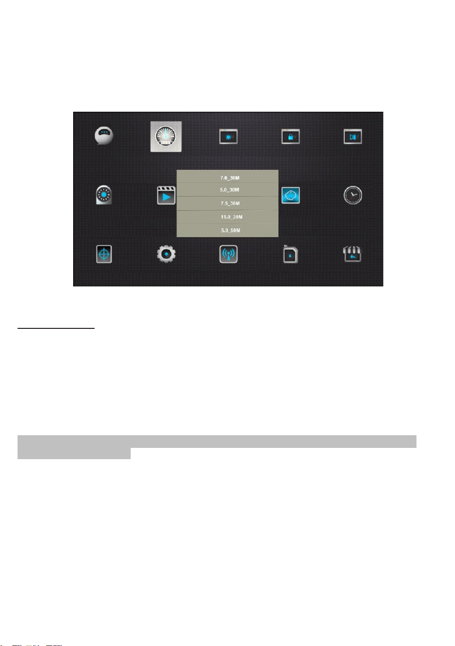
4.2 Display settings:
Screen brightness: You can set the display brightness of the screen.
Screensaver Touch to set the time of screen Saver.
4.3 System settings:
Language: Show the available languages: Chinese, Traditional Chinese, English, French, German,
Russian, Korean, Japanese.
Mirror: Touchto set: normal display; flip horizontal; flip vertical; flip horizontal & vertical.
Device Info: Reset and Password Switch / WiFi name and password/memory sizeofmicro SD
card, firmware version.
Reset:Itcan deleteall the settingsand restore to factory state and restart.
PasswordSwitch: Switch off, it directlyenters workingstate upon startup; switch on,itneeds to
enter a password to start working. The default password is 8888.
WiFi Switch: Touchto switchWiFion or off.
Format: Touch and check format micro SD card. Format will delete all thedatainmicro SD card.
Be sure to do a good job of data backup.
5.File Management
In the real-time image mode, press the [ ] key to enter the folder, and the user can
browse, play or delete recorded videos or photos.
During playing back a file, you can also delete or cancel the deletion of media files.
18
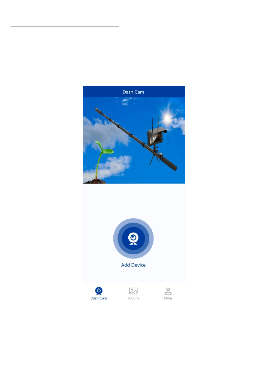
6.Inspection SYS APP Settings
Before runInspection SYS App, turnon WiFi of the monitor first. Findthe SSID name and password in
“ Unit”.
ThenaddtheWiFinetwork of themonitortotheWiFiconfigurationof the externaldevice.
Run APP, clickskip andchoose the agreement,thenAdd Device ( not activate).
19
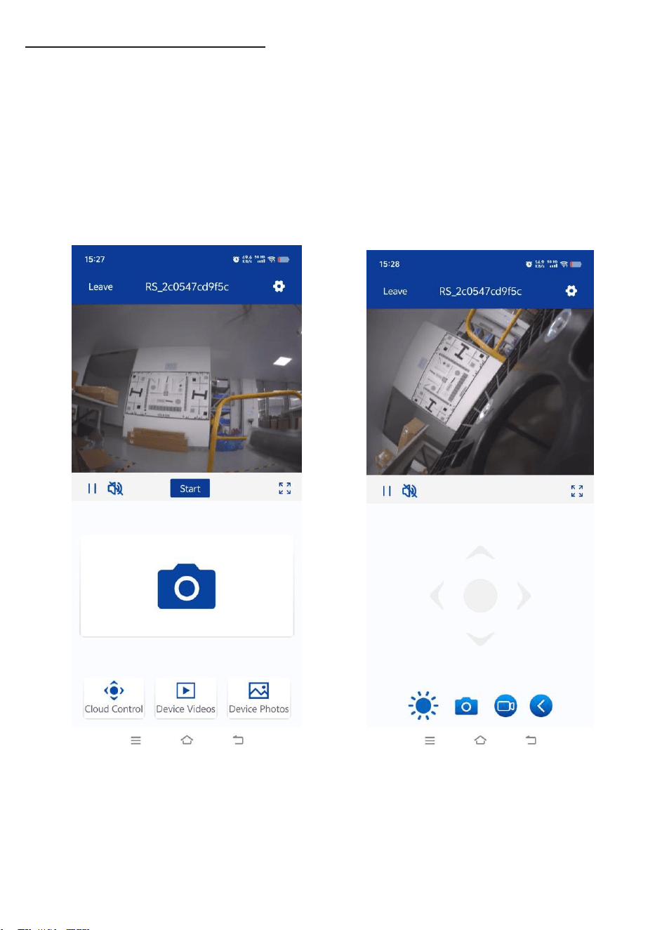
7.APP Monitoring Interface
Run Inspection SYS App, touch device to connect. After successful connection, it
automatically jumps to camera interface. You can take photo, recording, play and share.
Save the photo and recording files to monitor.
Enter into Video, play and load video locally.
Enter into Photo, play and load photo locally.
20
METER COUNTER OPERATION
1.Press the meter-zero button to set the meter to zero on screen display.
2. Touch to(meter/ft) to set the unit of length.
3.Choose the diameter and length of the cable on the meter counter.
Deviation inthe MC will be elevated if the cable is specified incorrectly.
PUSH CABLE AND CAMERA OPERATION
At thejob site
1. Always wear rubber gloves to operate the camera for health and safety reasons.
• When pushing, the end of your stroke should be as close to the entry as possible.
Standing too far back with an excess of cable between your hands and the entry may
cause the cable to fold on itself outside the entry and damage the cable.
• Try to keep the push cable away from sharp edge of a pipe entry because this may cause
damage. If the camera does not seem to go any farther, DO NOT FORCE TO PUSH THE
CAMERA! Try another entry if possible.
Warning
:
Handsshould be close to thelineopening. DONOTcatch the cable on the edge of an
entryand continue topush.
1.
Always try to run water down the pipe under going inspection. This will keep the system
much cleaner, and allow you to push noticeably farther with less friction. If the water is
preventing you from seeing an area of importance, temporarily turn it off.
2. When push the push cable through the pipeline by steady and slowly, a short distance
entry per time, keeps the hands at the entrance, so that can control the push cable and
prevent it stuck, bent or scratch.
3. Always try to run water down the pipe under going inspection. This will keep the system
much cleaner, and allow you to push noticeably farther with less friction. If the water is
preventing you from seeing an area of importance, temporarily turn it off.
4.
When push the push cable through the pipeline by steady and slowly, a short distance
entry per time, keeps the hands at the entrance, so that can control the push cable and
prevent it stuck, bent or scratch.
21
5. When inspecting a pipe, most of the time a slow steady push through the system works
the best. At changes in direction such as P-traps, Tee’s, Y’s, Elbows, etc. It is usually necessary to
give a little extra push in the bends.
6.
Make sure the sapphire window is clean prior to entry. Some users claim that a slight film of
detergent on the lens minimizes the possibility of grease sticking to the port. If necessary, take
advantage of any standing water in the pipe to wash the front of the camera by jiggling it in
the water.
7.
When you place the camera head into the pipe remember, as the materials of pipe vary, it
will be necessary to adjust the lighting settings to maximize picture quality.
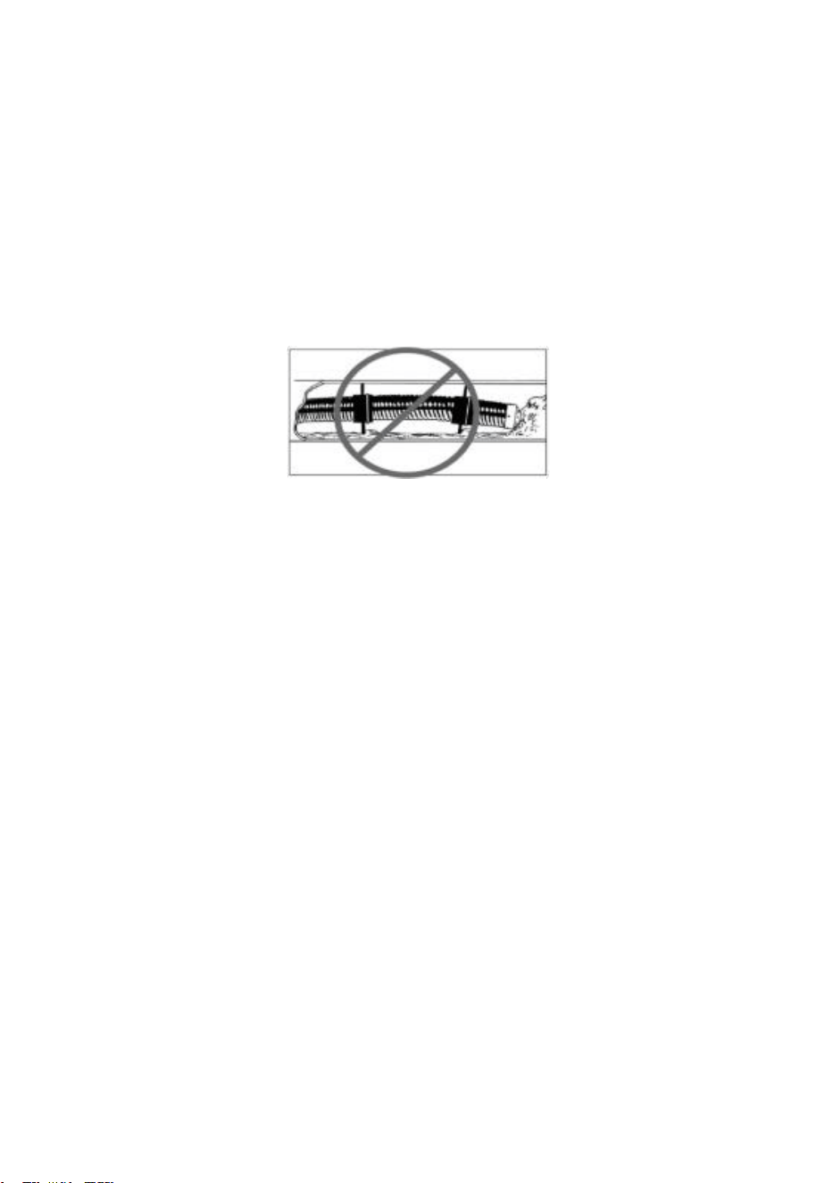
9. Thesystemcantravel through multiple 45and 90degreebends. Do not, however, try to force it
through a P-traporteeif there is a large amount ofresistance.
Figure 16. Improper operation

22
Warning: Donot tryto usethecamera headto clear obstructions.This System is a diagnostic tool,
not a draincleaner.
Usingthe camera head to clear obstructions could damagethecamera heador causeit to be
caught in the obstruction.
9. Do not attempt to remove or stores push cable on the reel solely by turning the reel itself.
You can manually push or pull cable from the reel and wind or unwind it.
10. If the camera sits in a pipe, or an enclosed environment, heat will build-up. This may lead
to the camera head overheating which will cause fuzzy lines to appear on the monitor. In the
event, this happens, turn off the system, remove the camera from the pipe (or enclosed
environment) and let the camera head cool for 10 to 15 minutes. Running water into the line
will also help cool the camera head. Always use the minimum illumination required to
maximize picture quality and to avoid excessive heat build-up.
Warning! Thecamera headcangetHOT!When finished withyour inspection, or if taking a
prolonged break in the middleof
the inspection, turnoff thesystem.
Retrieving the push cable
1. Once the inspection has been completed, pull the push cable back with slow, steady force.
Do not force the push cable or exert excessive force. This could damage the camera or push
cable. The push cable may get hung up while being retrieved, and may need to be
manipulated as did during insertion.
2. While take back the push cable, running water can be used to flush down the push cable.
After recycling, you can wipe the push cable with a towel.
Warning! NEVER USESOLVENTS to cleananypart ofthesystem. Substanceslike acetone and other
harsh chemicals
cancause cracking of the camera ring,which could affect waterproofing.
4.Storing the push cable into the cable reel. One hand holds the push cable, the other hand
close to the cable wheel. Slowly and gently push the push cable slide via the hook of the
handle, cable reel will rotate and store the push cable inside.
Warning! The hands should be close to the cable wheel when storingthe push cable. Push the push
cablea smallpiece
every try.Push a long distancecan cause the push cable bend or broken.

23
BATTERY SAFETY AND USING GUIDE
Using safety
Read the following battery precautions before charger, to reduce the risk of electrical shock.
1. Recharge batteries with accessory charging units.
2.Check the power units every time before using the equipment, be sure no problem, use of
unauthorized parts may result in electrical shock, fire and/or serious personal injury or damage
other instruments and system.
3. Never connects the car charger to any 24 volt cigarette lighter slot. It will harm the battery
and DVR.
4. Do not short circuit, it may cause fire, electrical shock.
5.Do not charge the battery under rain or wet conditions. Water entering the charger will
increase the risk of electrical shock.
6. If the charger and battery are damaged, do not use or stop to charge. It may cause
electrical shock.
7.Don’t disassemble the case, only qualified repair person can repair and maintenance.
8. Properly dispose of the battery. Exposure to high temperatures can cause the battery to
explode. So do not dispose of in a fire. Some countries have regulations concerning battery
disposal. Please follow all applicable regulations.
9. Do not touch anything which out from battery, which would burn or damage the skin, once
touches please flush with water. If in eyes, immediately get medical help fast.
Using Guide
Follow the steps as below to reduce the injury of the electric shock.
1.Power indicator LED will be red during charging, will be turned to green when charged fully.
If battery empty for a long term, it will pre-charge the battery automatically in 10 minutes, and
LED will be blinking in red.
2.It needs about 10 hours to charge the battery fully. The battery can charge online,
charging and supplying of work will not increase charging times.
3. User can use a power adaptor or car charger to charge the battery. If no use in a long term,
take a recharge per 6 month, to ensure the battery in normal working status.

24
OTHERS
Troubleshooting
Problem
Probable fault location
Solution
Confused image
show on screen
Wrong Camera Head option
Enter the setup menu and select the
correct camera
head type
The DVR do not
recognize SD memory
card.
SD Card is faulty.
Format the SD card using a PC.
Change an other SD memory card.
Gold fingers on the SD card are
dirty.
Clean the gold finger on the SD card.
SD card slot in the DVR may fault.
Check the SD card slot in the DVR .
No image
Cable connection faulty or loosely
Check cable connection, clean and
reconnect if necessary
Camera connector soiled
Clean the camera connector
Wrong SD memory card
Turn off power and replace SD card
Wrong setting
Enter the setup menu and select reset
DVR Can not boot
No power
Recharge
Transient short circuit in the
cable cause the battery short
circuit protection
Recharge the DVR more than 2 seconds
with adaptor or car-charger to activate
the battery
Can not input
Characters
The keyboard low battery
Chang battery
Keyboard fault
Check the Keyboard and the keyboard
on a PC
Thedeviationof MC
more than 0.5%
select the wrong total length
Press [ZERO] button within 3 seconds
after DVR monitor starts to select the
total length.
Pull out cable more than 3
meters before turning on the
system
Turn on the system before pulling out
the push cable from the cable reel
DVR charging
indicator lights up
green and cannot be
charged
The battery temperature
exceeds the range of -5~+48°C
Put the product under normal
temperature for 30 minutes to
automatically resume charging
When charging, the
yellow and green
charging indicator
lights are not on
Power adapter failure
Replace a power adapter
25
CAMERA OPTIONS
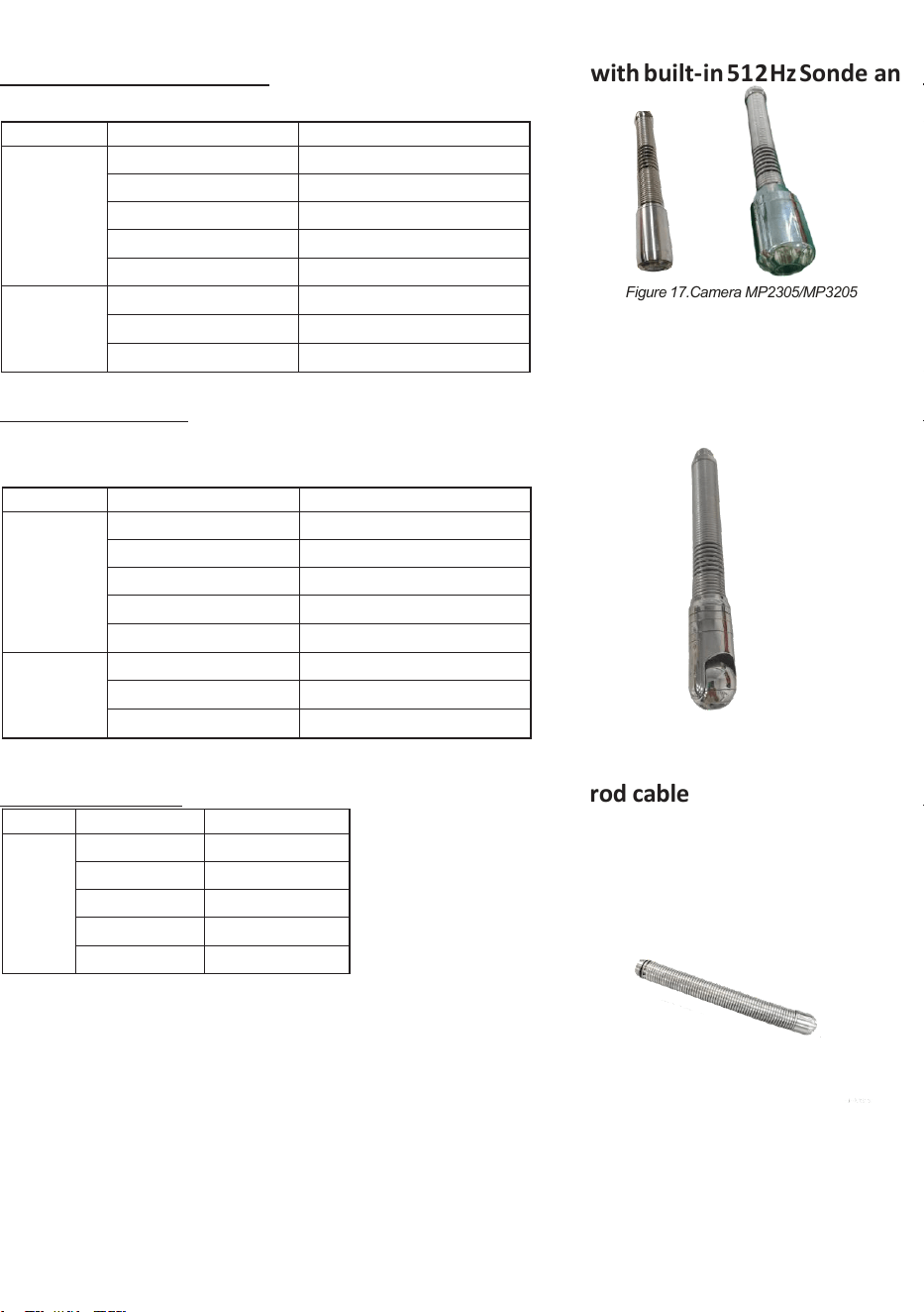
Camera MP2305/MP3205: 23mm&32mm camera headwith built-in 512Hz Sonde and
Self-leveling for 7.0mm or 7.5mm push rod cable
Type
Item
Parameter
Image
Sensor
1/3" CMOS
Resolution
AHD 2560×1440
View Angle
120°(diagonal)
Depth-of-Field
3-12cm(ø23)/8-30cm(ø32)
Front Lens
Sapphire
Transmitter
Frequency
512Hz
Transmit Mode
Constant
Transmission Distance
6 meters open area (max)
PT Camera MP35: 35mm camera with built-in 512Hz Sonde Focus Adjust 5-100cm
7.0mm or 7.5mm push rod cable
Type
Item
Parameter
Image
Sensor
1/3" CMOS
Resolution
AHD 2592×1944
View Angle
120°(diagonal)
Depth-of-Field
5-100cm(Focus adjustable)
Front Lens
Sapphire
Transmitter
Frequency
512Hz
Transmit Mode
Constant
Transmission Distance
6 meters open area (max)
Camera MP1410 :14mm camera head for 5.0mm push rod cable
Type
Item
Parameter
Image
Sensor
1/4" CMOS
Resolution
CVBS 100pixl
View Angle
100°(diagonal)
Depth-of-Field
2-8cm(approx)
Front Lens
Sapphire
Figure 17.Camera MP2305/MP3205
Figure 19.Camera MP35

This device complies with part 15 of the FCC Rules. Operation is subject to the
following two conditions: (1) This device may not cause harmful interference, and (2)
this device must accept any interference received, including interference that may cause
undesired operation.
Any Changes or modifications not expressly approved by the party responsible for
compliance could void the user's authority to operate the equipment.
Note: This equipment has been tested and found to comply with the limits for a Class B
digital device, pursuant to part 15 of the FCC Rules. These limits are designed to
provide reasonable protection against harmful interference in a residential installation.
This equipment generates uses and can radiate radio frequency energy and, if not
installed and used in accordance with the instructions, may cause harmful interference
to radio communications. However, there is no guarantee that interference will not
occur in a particular installation. If this equipment does cause harmful interference to
radio or television reception, which can be determined by turning the equipment off and
on, the user is encouraged to try to correct the interference by one or more of the
following measures:
-Reorient or relocate the receiving antenna.
-Increase the separation between the equipment and receiver.
-Connect the equipment into an outlet on a circuit different from that to which the
receiver is connected.
-Consult the dealer or an experienced radio/TV technician for help.
-This equipment complies with FCC radiation exposure limits set forth for an
uncontrolled environment. This equipment should be installed and operated with
minimum distance 20cm between the radiator & your body.

