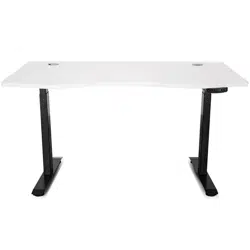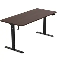
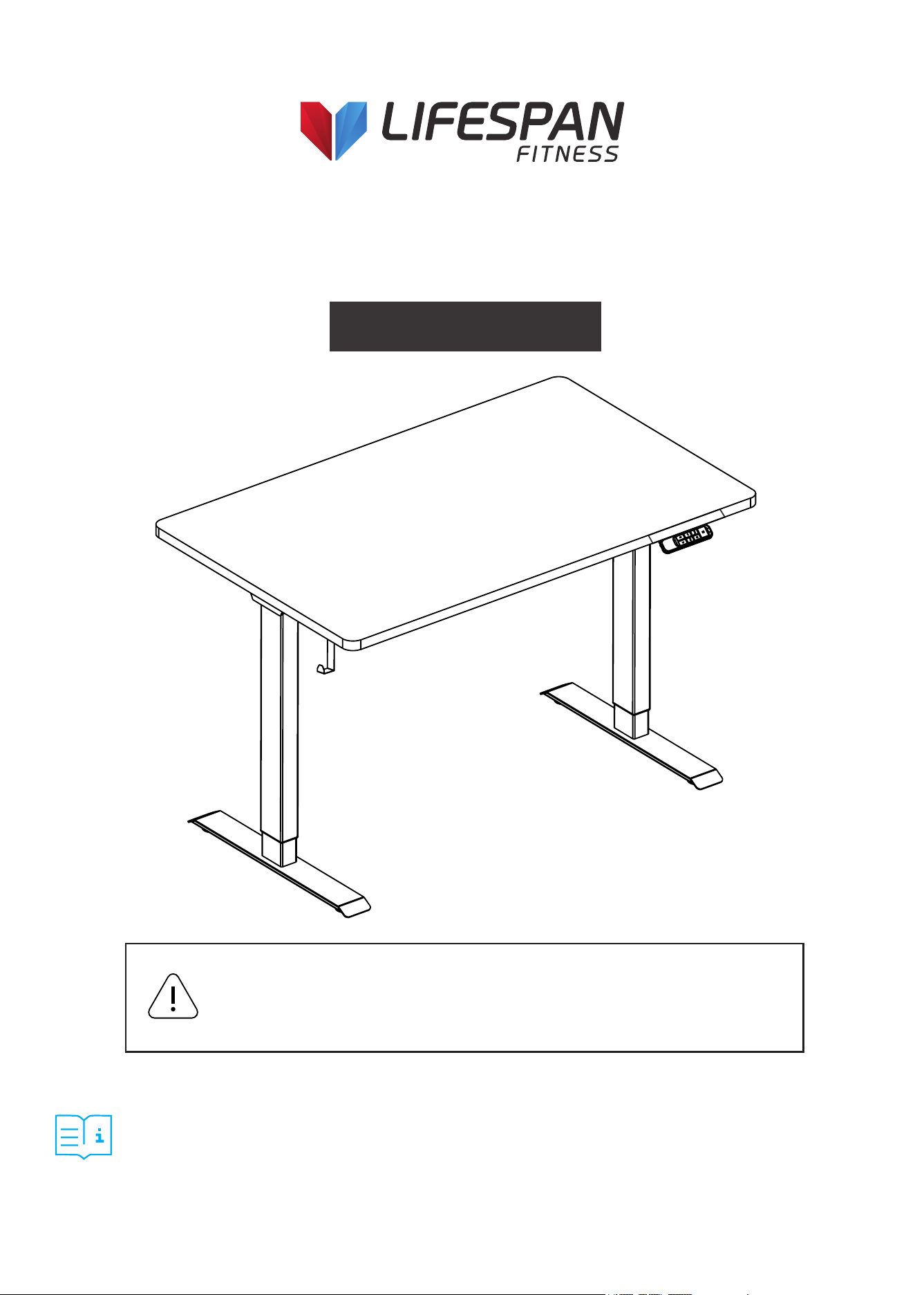
PRODUCT MAY VARY SLIGHTLY FROM THE ITEM PICTURED DUE TO MODEL UPGRADES.
READ ALL INSTRUCTIONS CAREFULLY BEFORE USING THIS PRODUCT.
RETAIN THIS OWNER’S MANUAL FOR FUTURE REFERENCE.
NOTE:
THIS MANUAL MAY BE SUBJECT TO UPDATES OR CHANGES. UP TO DATE MANUALS ARE AVAILABLE THROUGH OUR
WEBSITE AT WWW.LIFESPANFITNESS.COM.AU
ErgoDesk Electric Standing Desk
Top (160cm/180cm) and Frame
USER MANUAL
CAUTION: Make sure there are no obstacles in the desk’s path and that all cords
are of appropriate length for desk movement. Failure to comply with or follow all
assembly, safety, and operation instructions and warnings regarding the use of
this product may result in serious property damage or bodily injury.

2
TABLE OF
CONTENTS
I. Important Safety Instructions . . . . . . . . . . . . . . . . . . . . . . . . . . . . . . .
II. Setup and Installation . . . . . . . . . . . . . . . . . . . . . . . . . . . . . . . . . . . . . . .
III. Parts List . . . . . . . . . . . . . . . . . . . . . . . . . . . . . . . . . . . . . . . . . . . . . . . . . . . . .
IV. Assembly Instructions . . . . . . . . . . . . . . . . . . . . . . . . . . . . . . . . . . . . . . .
V. Operation Instructions . . . . . . . . . . . . . . . . . . . . . . . . . . . . . . . . . . . . . . . .
VI. Warranty . . . . . . . . . . . . . . . . . . . . . . . . . . . . . . . . . . . . . . . . . . . . . . . . . . . . .
03
05
06
07
12
17
| TABLE OF CONTENTS

3IMPORTANT SAFETY INSTRUCTIONS |
I. IMPORTANT SAFETY INSTRUCTIONS
WARNING: Read this manual carefully before operating this equipment.
NOTE: Follow all instructions to prevent accidents, injury, or equipment
damage.
GENERAL SAFETY
OPERATION SAFETY
• Improper use may cause property damage or bodily injury.
• Keep children and pets away from the desk during operation.
• These desks are designed only for the purposes described in this manual. Any other use is at the
user’s risk.
• Do not use in environments with high humidity or dampness.
• Do not sit, stand, or lie on the desk.
• Do not move around, crawl, or lie under the desk frame.
• Do not place objects over 100 kg on the desktop.
• Avoid adjusting the desk height more than 20 times in a short period. Allow a 10-minute rest before
reuse.
• Unplug the power cord during thunderstorms or if the desk will not be used for an extended period.
• Do not immerse in water. Keep the desk away from liquids and heat sources.
• Do not disassemble or repair the product yourself. Only certified personnel may perform repairs.
• Ensure there are no obstacles in the desk’s path and no objects within 20 inches (500 mm)
underneath the desk.
• Body parts or items can be crushed if trapped between the desk and an immovable object.
• Keep hands and body parts clear of moving components to prevent pinching.
• Although the desk includes anti-collision protection, always supervise movement.
• Note: The anti-collision function is disabled during the reset process.
• Keep an eye on the desk while lowering or raising it.
• Ensure all cables and device cords are long enough for full range of motion. Items that are pulled off
the desk may fall and cause damage or injury.
• Do not use the desk if it malfunctions.

4 | IMPORTANT SAFETY INSTRUCTIONS
ENVIRONMENT & MAINTENANCE
USAGE
• Operating temperature: 0°C – 40°C.
• Keep away from excessive humidity, extreme temperatures, corrosive gases, liquids, and dust.
• Turn off and unplug power before cleaning or inspection.
• Do not use water, alcohol, or strong cleaning chemicals. Use a dry or slightly damp cloth only.
• A manual reset is required after initial installation or power loss.
• The company accepts no liability or warranty for damage or injury caused by improper or abnormal
operation.
• The desk height is adjustable to promote ergonomic working posture.
• Designed for indoor use only as described in this manual.
• Children should only use the desk under adult supervision.
• Under no circumstances does the manufacturer accept warranty or liability claims for damages
caused by improper use or handling of the desk beyond what is described in this operation manual.

5IMPORTANT ELECTRICAL INFORMATION |
II. SETUP AND INSTALLATION
• Once the desk has been assembled, adjust the feet so that the desk is level and does not shift during
use.
• After leveling, connect the desk to a 110V or 240V outlet. The desk is now ready for use.
• Check that no cables can get jammed or pinched during movement.
• Choose a placement for the desk that is a safe distance from window frames, radiators, furniture, and
walls to avoid people getting stuck or trapped.
• Ensure the desktop does not touch the wall during movement.
• Do not place any objects taller than 50 cm (20") underneath the desk.
• After assembly, when moving the desk, DO NOT lift the desk by the desktop. This can stress the
fasteners connecting the desk base to the desktop.
• To move the desk, lower it completely and lift from the desk base, or remove the desktop first.
6 | PARTS LIST
III. PARTS LIST
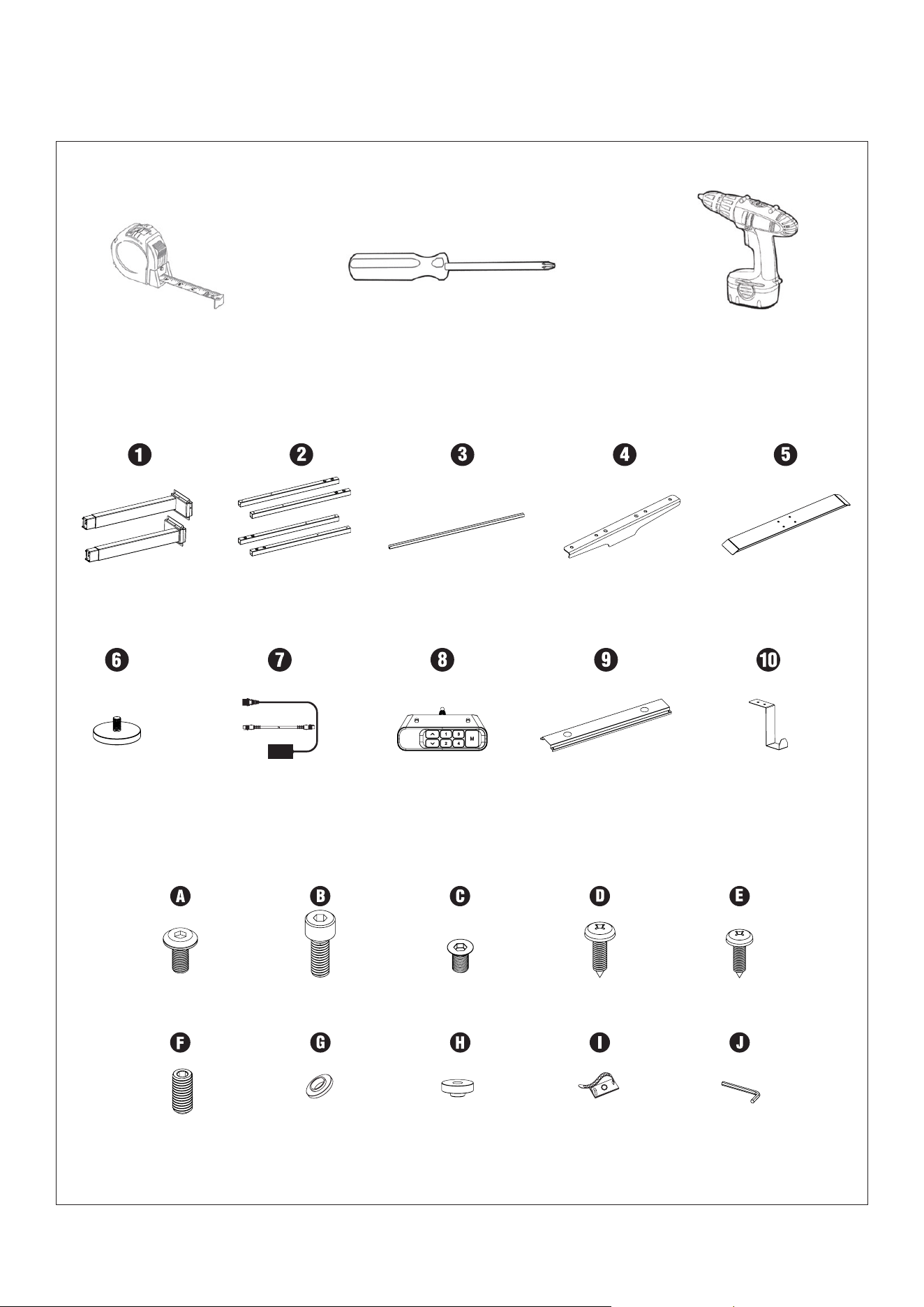
TOOLS REQUIRED
Tape Measure Philips Head Screwdriver Power Drill
COMPONENTS
HARDWARE
Lifting Column *2
Leveling Studs *4
M6x10 Screws
8pcs
M8x20 Screws
8pcs
Washers (Attached
to the Side Bracket)
8pcs
Cable Clips
5pcs
Allen Key 4mmWashers (Attached
to the Centre Rail)
2pcs
M6x16 Screws
8pcs
M6x8 Screws
4pcs
M5x18 Screws
12pcs
M4x16 Screws
2pcs
Wires *2 Handset *1 Magnetic Cable Tray *1 Desk Hook *1
Crossbar End *4 Crossbar Center Rails *2 Side Bracket *2 Foot *2
7ASSEMBLY INSTRUCTIONS |
IV. ASSEMBLY INSTRUCTIONS
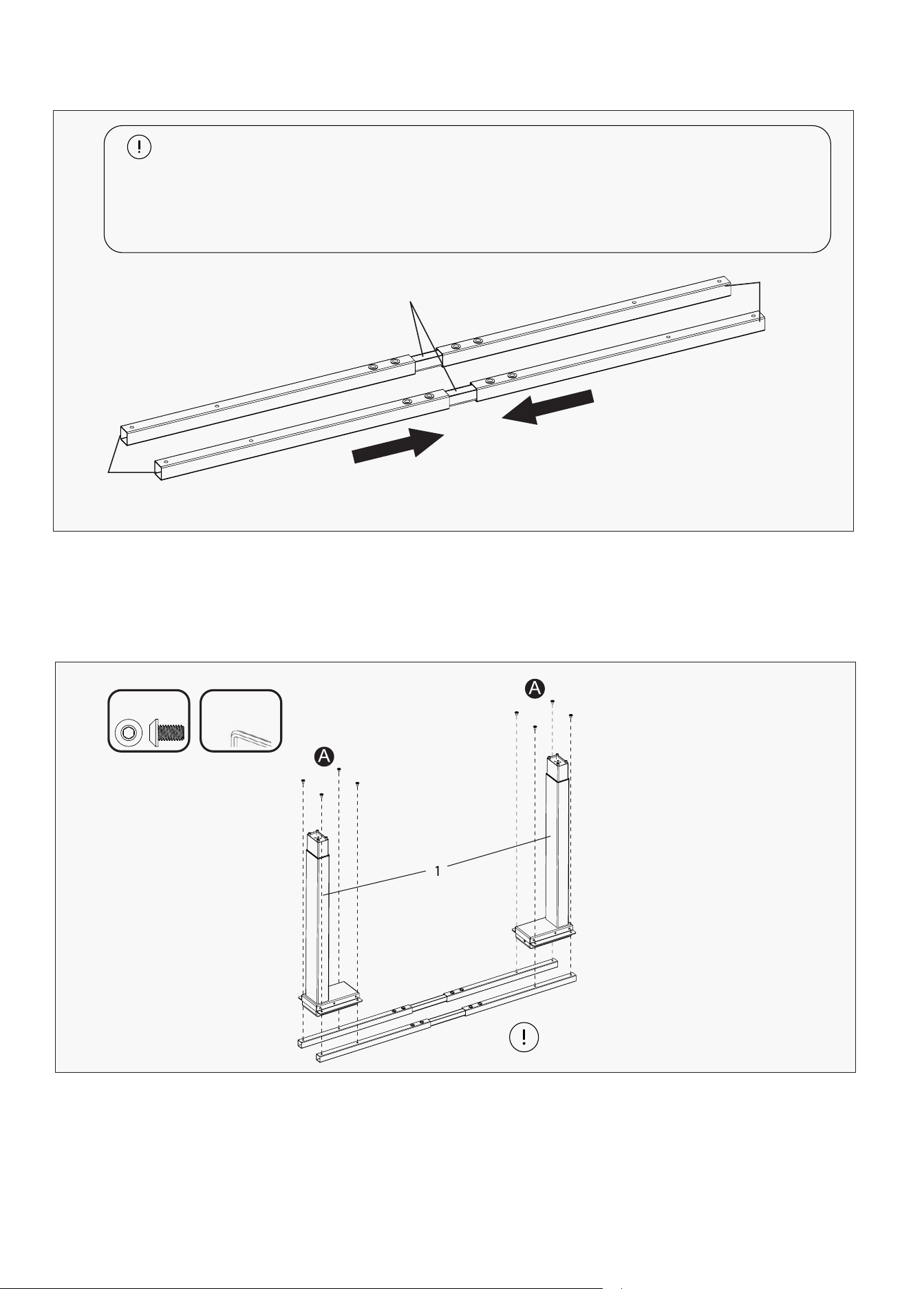
STEP 1: Pull Out the Frame
STEP 2: Attach Legs to Frame
a. Lay out all components and hardware to confirm that all parts are included.
b. Place the Crossbar End (2) into the two Crossbar Center Rails (3).
Take note of the the direction the bolt hole is facing.
a. Align the Crossbar End (2) with the Lifting Column (1). Insert the M6 x 10 mm Screws (A) and tighten using the 4
mm Allen key.
b. Repeat the same process for the other side.
Installation Tips
- Do not fully tighten the screws during initial assembly. Once all parts are properly aligned, go
back and tighten all screws securely.
- Lay down a soft mat or old blanket before assembly to protect both the floor and the furniture
from scratches or damage.
3
2
2
1
Avoid over-tightening the screws as this
may damage the product.
Allen key
4mm
A x 8
8 | ASSEMBLY INSTRUCTIONS
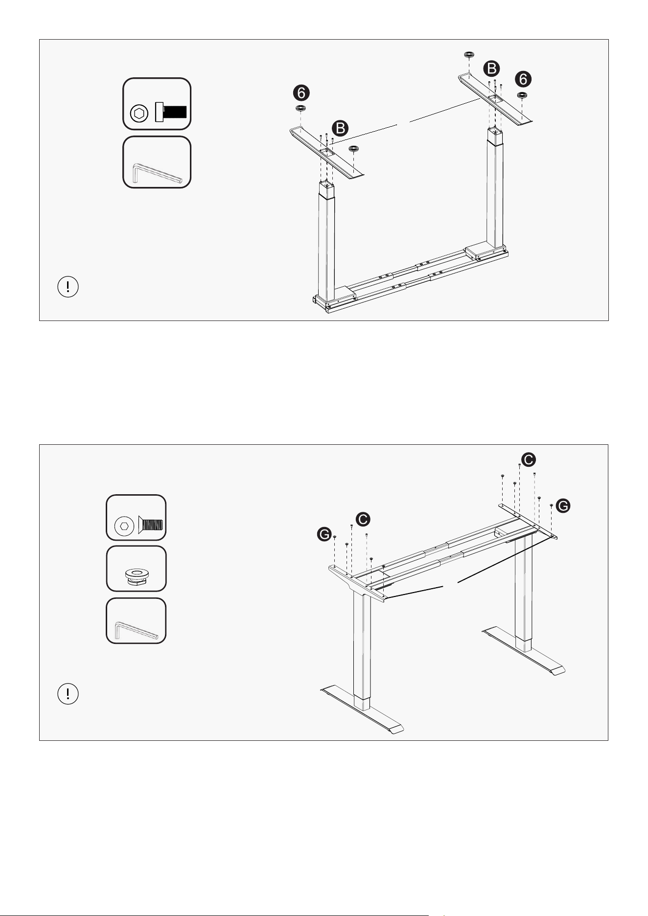
STEP 3: Attach Foot
STEP 4: Attach Side Bracket
a. Attach the Leveling Studs (6) to the Foot (5).
b. Align the Foot (5) with the Lifting Column (1), then insert four M6x16 mm Screws (B) into the holes on
the underside of the foot and tighten using the 4 mm Allen key.
c. Repeat the process for the other side.
a. Turn the table onto the feet and align the two holes on the Side Bracket (4) with the Crossbar End (2).
Insert two M6x8 mm Screws (C) and tighten using the 4 mm Allen key.
b. On the outer four holes of the side bracket insert Washers (G).
c. Repeat the process for the other side.
Avoid over-tightening the screws as this
may damage the product.
Avoid over-tightening the screws as this
may damage the product.
5
Allen key
4mm
B x 8
4
Allen key
4mm
C x 4
G x 8
9ASSEMBLY INSTRUCTIONS |
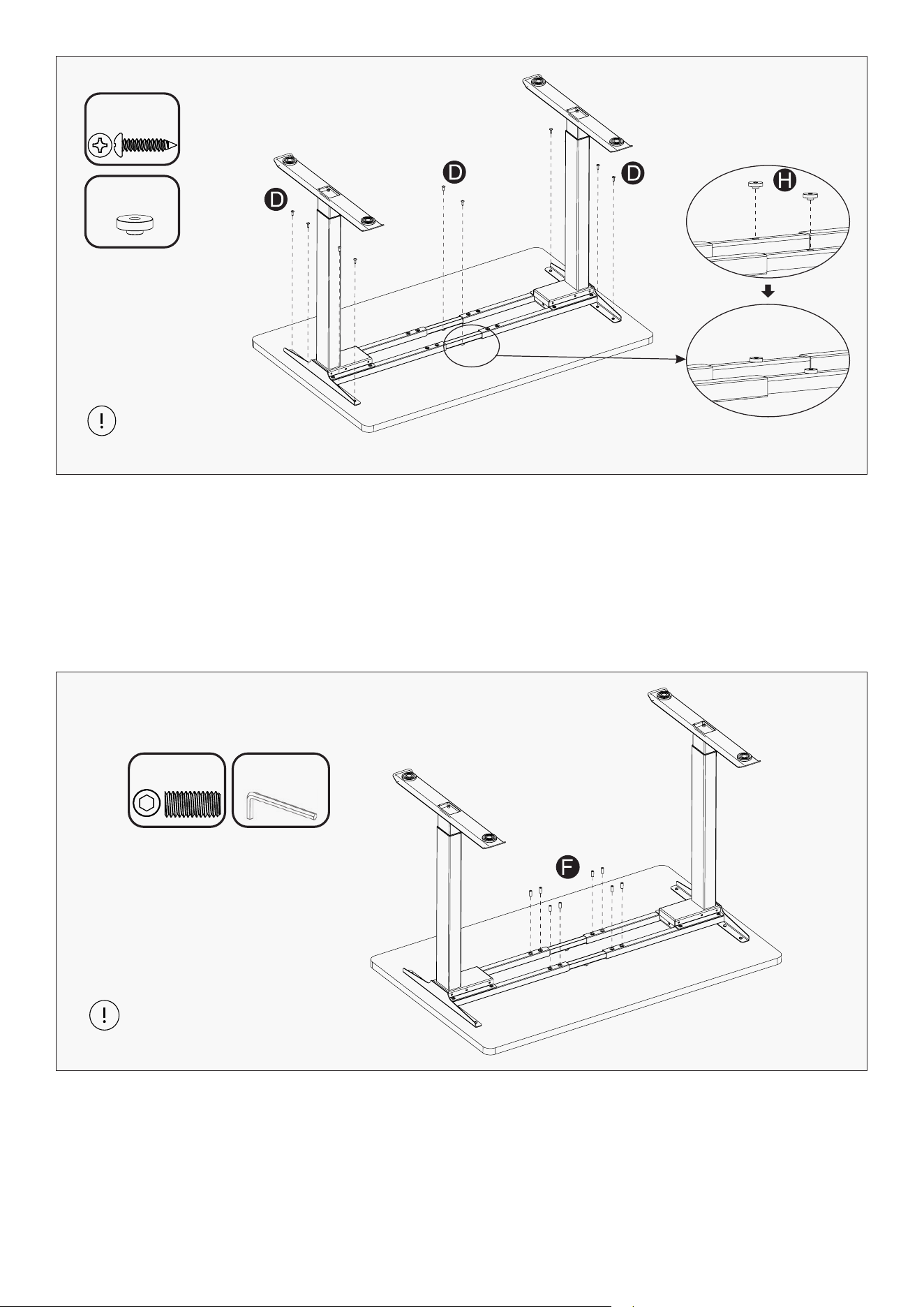
a. Attach the Washers (H) onto the Crossbar Center Rails (3).
b. With assistance, flip the frame onto the underside of the Table Top, lining up with the bolt holes. It is
recommended that the frame side boards on both ends are positioned 50 mm from the edge of the tabletop.
Secure the frame using M5x18 mm Screws (D) and tighten.
a. Use M8x20 mm Screws (F) to fasten the Crossbar Ends (2) and the Crossbar Center Rails (3), then
tighten using the 4 mm Allen Key.
STEP 5: Attach Frame Set to Tabletop
STEP 6: Locking Frame Screws
Avoid over-tightening the
screws as this may damage
the product.
D x 10
H x 2
F x 8
Allen key
4mm
Avoid over-tightening the screws as this
may damage the product.
10 | ASSEMBLY INSTRUCTIONS
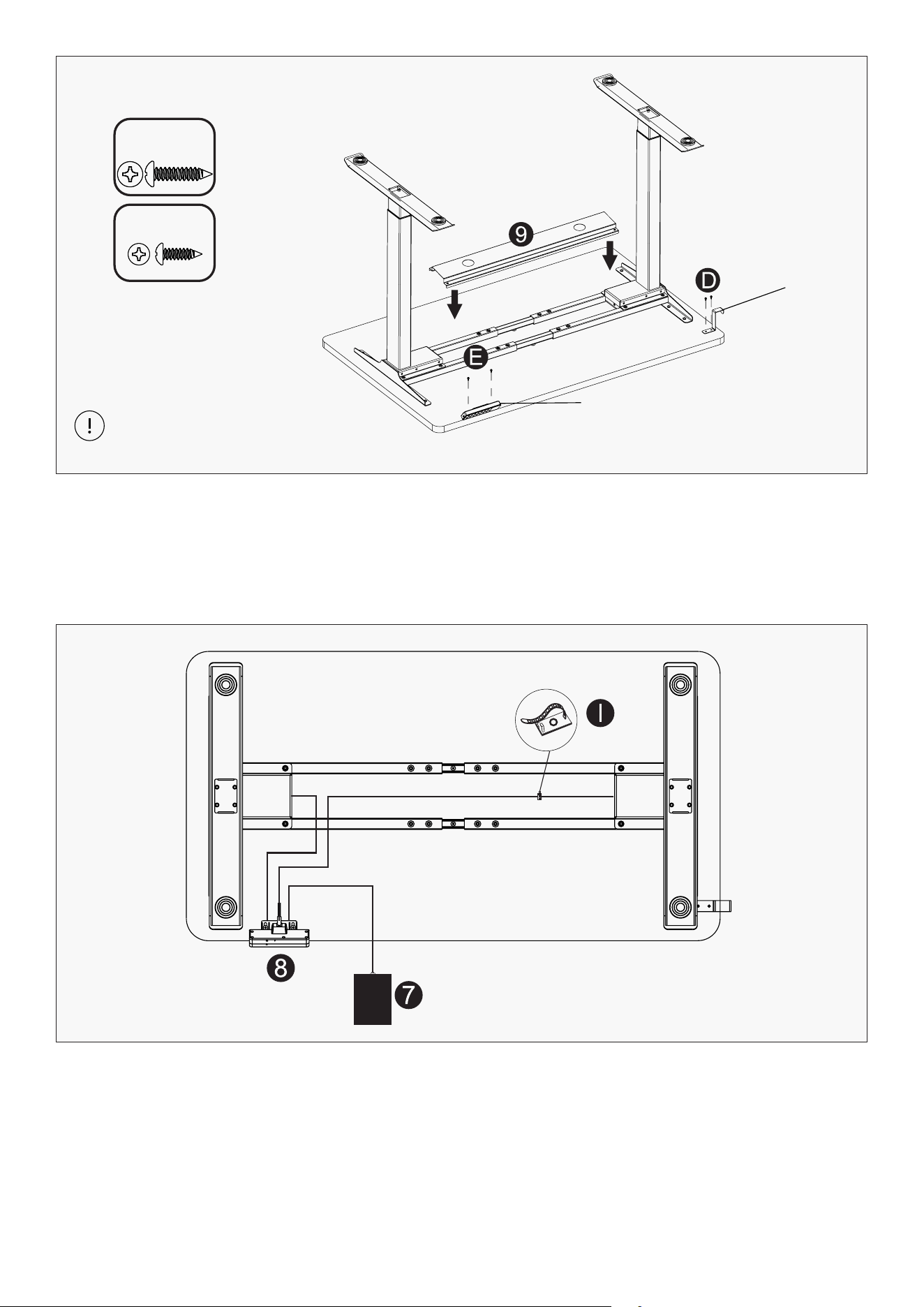
a. Secure the Handset (8) to the tabletop with 2xM4x16 mm Screws (E).
b. Secure the Desk Hook (10) with 2xM5x18 mm Screws (D). Handset and hook can be on either side.
c. After step 9, attach the magnetic cable management (9) to the frame.
a. Connect the cable from Lifting Column (1) to the Handset (8). Then connect the cable from the other
lifting column to the Handset (8).
b. Connect the Adapter Plug (7) to the Handset (8).
c. Use Cable Clips (I) to hold the cables under the desk.
STEP 7: Attach Handset & Hanger
STEP 8: Connect Cables
Avoid over-tightening the screws as this
may damage the product.
D x 2
E x 2
8
10
11USAGE INSTRUCTION |
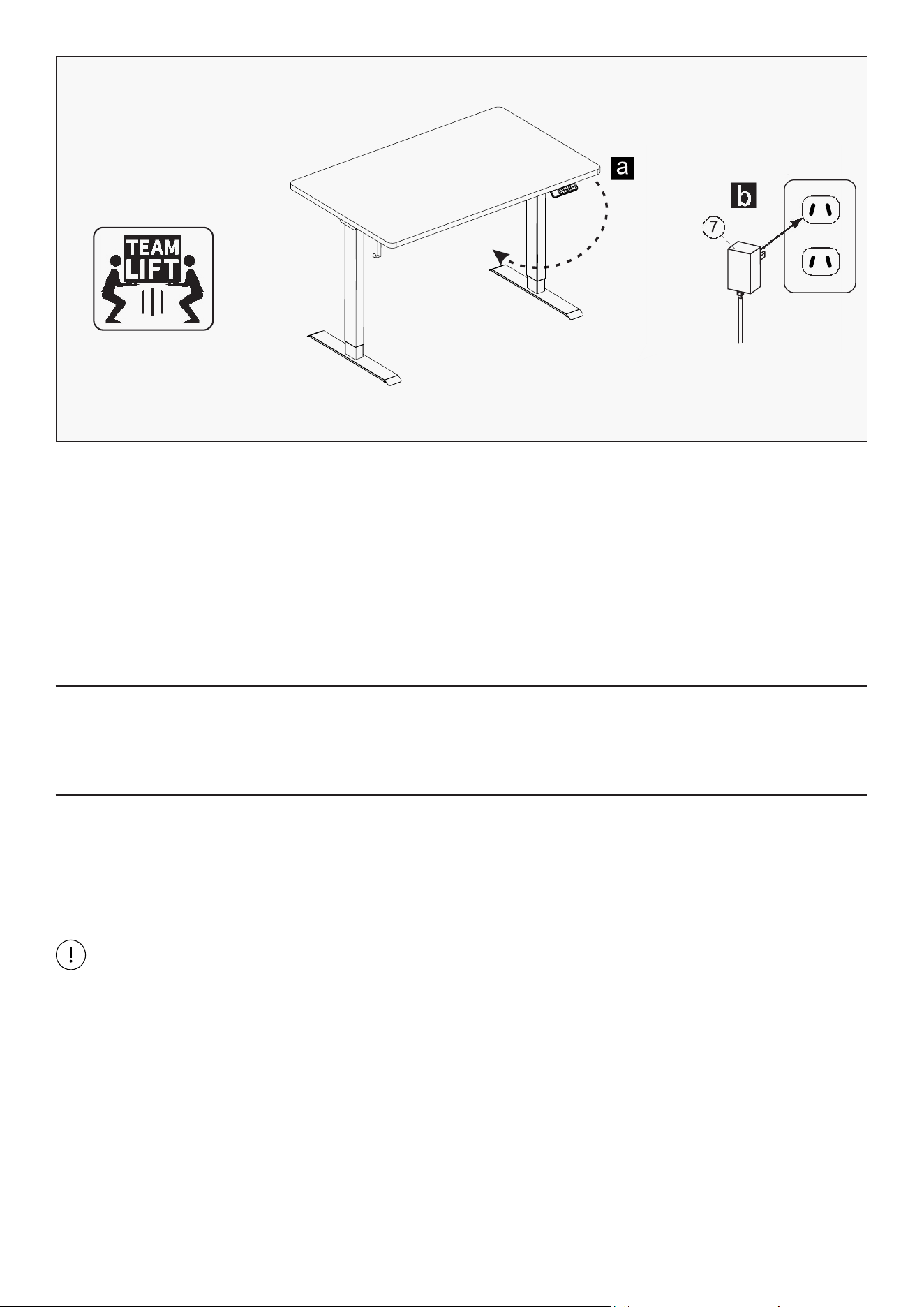
a. With the desk at its lowest height, carefully turn the assembled desk upright with the help of at least
two people.
b. Plug the Power Cord (7) into a 110–240V outlet.
IMPORTANT NOTE:
- Lift the desk frame, not the desktop, when turning the desk upright.
- Always use at least two people when lifting.
Caution: The desk is heavy.
If necessary, adjust the leveling studs to ensure the desk is stable and level. Unscrew to increase height
and screw in to decrease height.
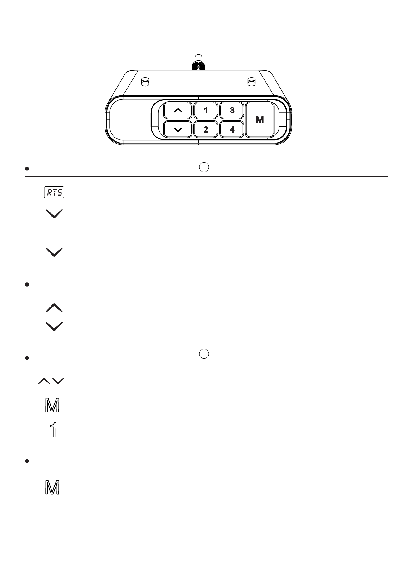
a. Press and hold the “▼” (down) button until the desk reaches its lowest position.
b. Continue holding the “▼” (down) button for 5 seconds until a beep is heard.
The desk will reset. Your desk is now ready to use.
IMPORTANT
You must complete this initialization step or the desk will NOT function properly.
Hold down the down arrow until the desk moves slightly upward after reaching the bottom—this
confirms reset.
STEP 9: Set Desk Upright and Connect Power
STEP 10: Adjust Leveling Studs
STEP 11: Initialize
12 | USAGE INSTRUCTION
V. OPERATION INSTRUCTIONS
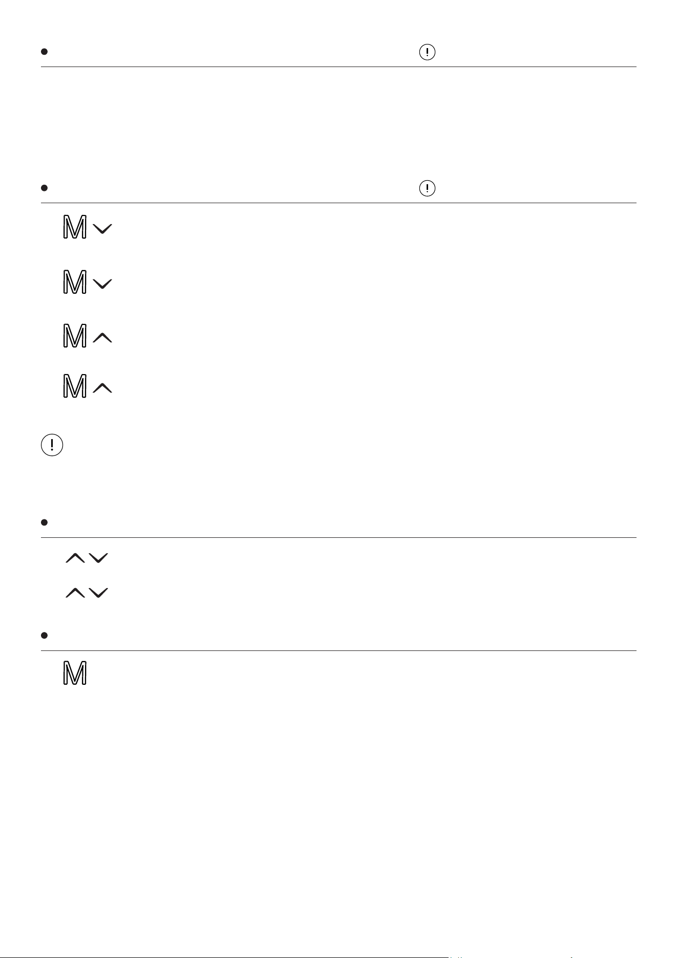
When the system is abnormal or the handset displays "RST", the desk must be reset.
Press the “▲” (up) button to adjust the desk height upward.
Press the “▼” (down) button to adjust the desk height downward.
Use the ▲ / ▼ buttons to move the desk to your desired height.
a. Press the M button.
b. Then use the ▲ and ▼ buttons to select the reminder interval (hours).
c. When a small dot appears on the screen, the reminder is set successfully.
Press and hold the M button until "S–" appears on the display.
* Press a number key (e.g. "1") to save the current height to Memory 1.
* Keys "2" to "4" can be set using the same steps.
* Press and hold the “▼” (down) button to lower the desk to its lowest height.
* Release the button, then press and hold “▼” again until "RST" appears on the display and a
beep is heard.
Release the “▼” button. The reset is now successful, and the desk can be used normally.
Reset
Up and Down
Memory Function
Time Reminder
Reset after the initial installation or power failure.
By memorizing a height position, you can return to it with one click.
(Note: Models with only two buttons do not support this function.)
1
1
1
1
2
2
2
3
3
13
USAGE INSTRUCTION |
NOTE:
Once limits are set, the desk will not move beyond the saved lowest or highest positions.
A beep sound confirms when a limit is set or cancelled.
* If the tabletop encounters an obstacle while raising or lowering, it will automatically stop and
move in the opposite direction.
* After reversing a short distance, the desk will stop and can be used normally once the obstacle
is removed.
Anti-Collision Protection
Minimum and Maximum Limit Setting
Child Lock
Entering Parameter Setup
Before using the desk, ensure the area around
and under the desk is clear of obstacles.
Do not set this function unless necessary.
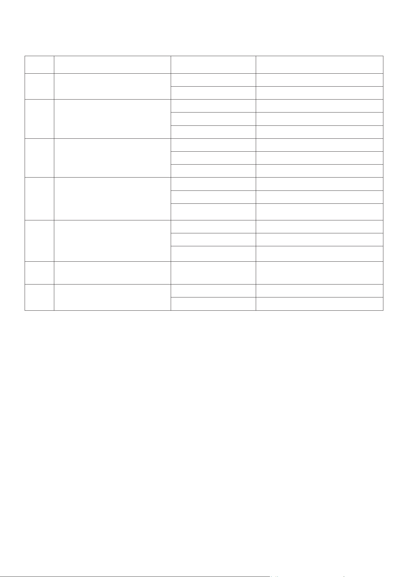
To set the lowest position limit, move the desk to the desired lowest height, then press
and hold M + ▼ for 5 seconds until a beep sounds. The lowest position is now stored.
Press and hold the M key for 10 seconds to enter the setup interface.
The display will show x-y flashing, where:
* x = parameter group
* y = parameter value
You can switch parameter groups by pressing SET, and adjust the parameter value by
pressing the ▲ (up) or ▼ (down) buttons.
Once the desired value is set, press and hold the M key again for 10 seconds to save and
return to the normal display.
To cancel the lowest position limit, move the desk to any height and press and hold M +
▼ for 5 seconds until a beep sounds. The lowest position limit is now cleared.
To set the highest position limit, move the desk to the desired highest height, then press
and hold M + ▲ for 5 seconds until a beep sounds. The highest position is now stored.
To cancel the highest position limit, move the desk to any height and press and hold M +
▲ for 5 seconds until a beep sounds. The highest position limit is now cleared.
1
1
2
3
4
To lock: hold “▲” + “▼” for 5 seconds until "LOC" appears.
To unlock: Hold again for 5 seconds until display returns normal.
1
2
14 | USAGE INSTRUCTION
Available Parameters
Code Function Value (y) Description
1–y Unit of measurement
0 Cm (Centimeters)
1 Inch
2–y
Anti-collision sensitivity
(gyro sensor)
0 Off
1 Most sensitive
8 Least sensitive
3–y
Anti-collision sensitivity
when moving up
0 Off (Not recommended)
1 Most sensitive
8 Least sensitive
4–y
Anti-collision sensitivity
when moving down
0 Off (Not recommended)
1 Most sensitive
8 Least sensitive
5–y
Anti-collision sensitivity
when tilted/slanted
0 Off (Not recommended)
1 Most sensitive
8 Least sensitive
yyy
Minimum frame height
(without tabletop)
yyy Lowest height value in cm/inch
(based on setting 1–y)
7–y Key control mode
0 Constant press required
1 One-touch control

15TROUBLESHOOTING |
Troubleshooting
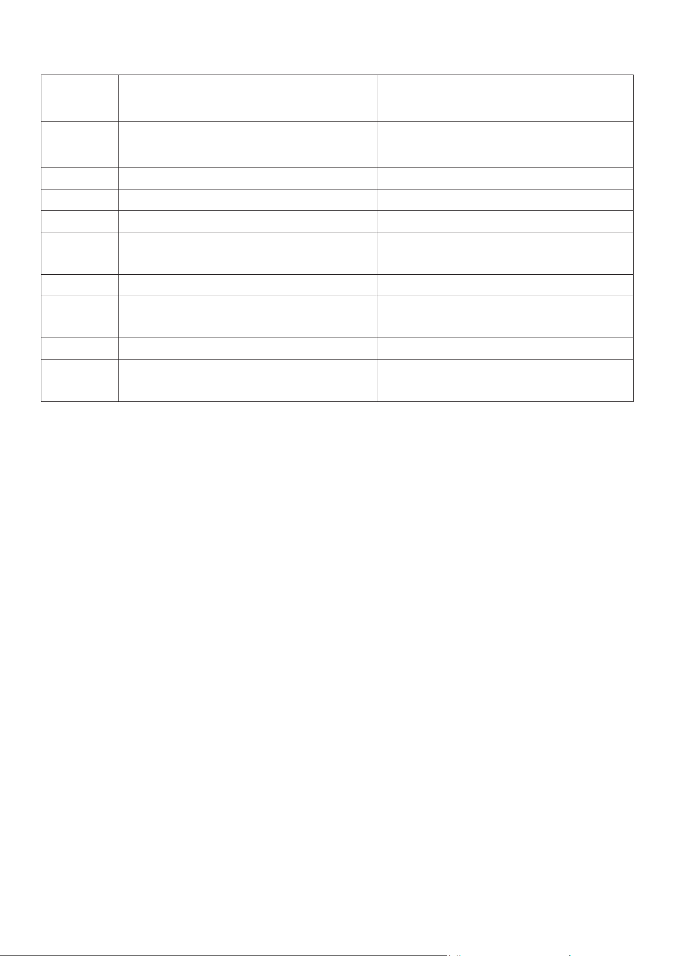
Error Code Possible Cause Solution
E01 Main power supply voltage is too high Check the main power supply
E02
Height deviation between screw rods
exceeds 1 cm
Reinitialize
E03 Controller is not connected Connect the controller
E04 Hand controller communication error Check the hand controller wiring
E05
Desk moves backward when
encountering obstacles
Place the control box flat or remove
obstacles
E06 Main power supply failed to start
Replace the power supply or check the
power supply connection cable
E07
Protection triggered during power
supply operation
Power on again
E08 Desktop tilts during operation Reinitialize
E09 / Hot Power supply temperature is too high
Allow temperature to decrease, turn off
power, or rest 18 minutes before use
E11 Motor 1 is not connected Check connecting wires
E12 Motor 1 current sampling channel error Replace control board
E13
Motor 1 missing phase / phase lines
disconnected
Check motor wiring connections
E14
Motor 1 Hall sensor error or Hall wire
disconnected
Check Hall signal or replace wire
E15 Motor 1 internal short circuit Replace faulty motor
E16 Motor 1 is stuck Reinitialize
E17 Motor 1 running in wrong direction Swap motor wire or Hall wire
E18
Motor 1 overloaded due to excessive
load
Reduce load
E21 Motor 2 is not connected Check wiring / connectors
E22
Motor 2 current sampling channel
error
Replace control board
16 | TROUBLESHOOTING
E23
Motor 2 missing phase / phase lines
disconnected
Check motor wiring connections
E24
Motor 2 Hall sensor error or Hall wire
disconnected
Check Hall signal or replace wire
E25 Motor 2 internal short circuit Replace faulty motor
E26 Motor 2 is stuck Reinitialize
E27 Motor 2 running in wrong direction Swap motor wire or Hall wire
E28
Motor 2 overloaded due to excessive
load
Reduce load
E40 Controller disconnection in series Check connecting wires
E41 Serial signal error
Check connecting wires or replace
controller
E42 Memory error Replace controller
E43
Obstruction detected and sensor
stopped
Replace controller
17
VI. WARRANTY
AUSTRALIAN CONSUMER LAW
Many of our products come with a guarantee or warranty from the manufacturer. In addition, they come
with guarantees that cannot be excluded under the Australian Consumer Law. You are entitled to a
replacement or refund for a major failure and compensation for any other reasonably foreseeable loss
or damage.
You are entitled to have the goods repaired or replaced if the goods fail to be of acceptable quality and
the failure does not amount to a major failure. Full details of your consumer rights may be found at
www.consumerlaw.gov.au.
Please visit our website to view our full warranty terms and conditions:
http://www.lifespanfitness.com.au/warranty-repairs
WARRANTY AND SUPPORT
Any claim against this warranty must be made through your original place of purchase.
Proof of purchase is required before a warranty claim may be processed.
If you have purchased this product from the Official Lifespan Fitness website, please visit
https://lifespanfitness.com.au/warranty-form
For support outside of warranty, if you wish to purchase replacement parts or request a repair or
service, please visit https://lifespanfitness.com.au/warranty-form and fill in our Repair/Service
Request Form or Parts Purchase Form.
Scan this QR code with your device to go to lifespanfitness.com.au/warranty-form
WARRANTY |



WWW.LIFESPANFITNESS.COM.AU