Operator’s Manual
RZ-HD, RZ-XD, RT, and SRT Series
Riding Mowers
For 2025 Models
3473-292B
Original Instructions (EN)
*3473-292*B

Table of Contents
Chapter 1: Introduction........................................................................................................................ 1–1
Intended Use ..................................................................................................................................... 1–1
Getting Help....................................................................................................................................... 1–1
Safety-Alert Symbol ......................................................................................................................... 1–2
Chapter 2: Safety.................................................................................................................................. 2–1
General Safety .................................................................................................................................. 2–1
Slope Indicator .................................................................................................................................. 2–2
Safety and Instructional Decals .................................................................................................... 2–3
Chapter 3: Product Overview ............................................................................................................ 3–1
Controls............................................................................................................................................... 3–2
Control Panel................................................................................................................................. 3–2
Key Switch ..................................................................................................................................... 3–2
Power-Takeoff (PTO) Switch ..................................................................................................... 3–3
Throttle Control ............................................................................................................................. 3–3
Choke Control ............................................................................................................................... 3–3
Hour meter ..................................................................................................................................... 3–3
Motion-Control Levers................................................................................................................. 3–4
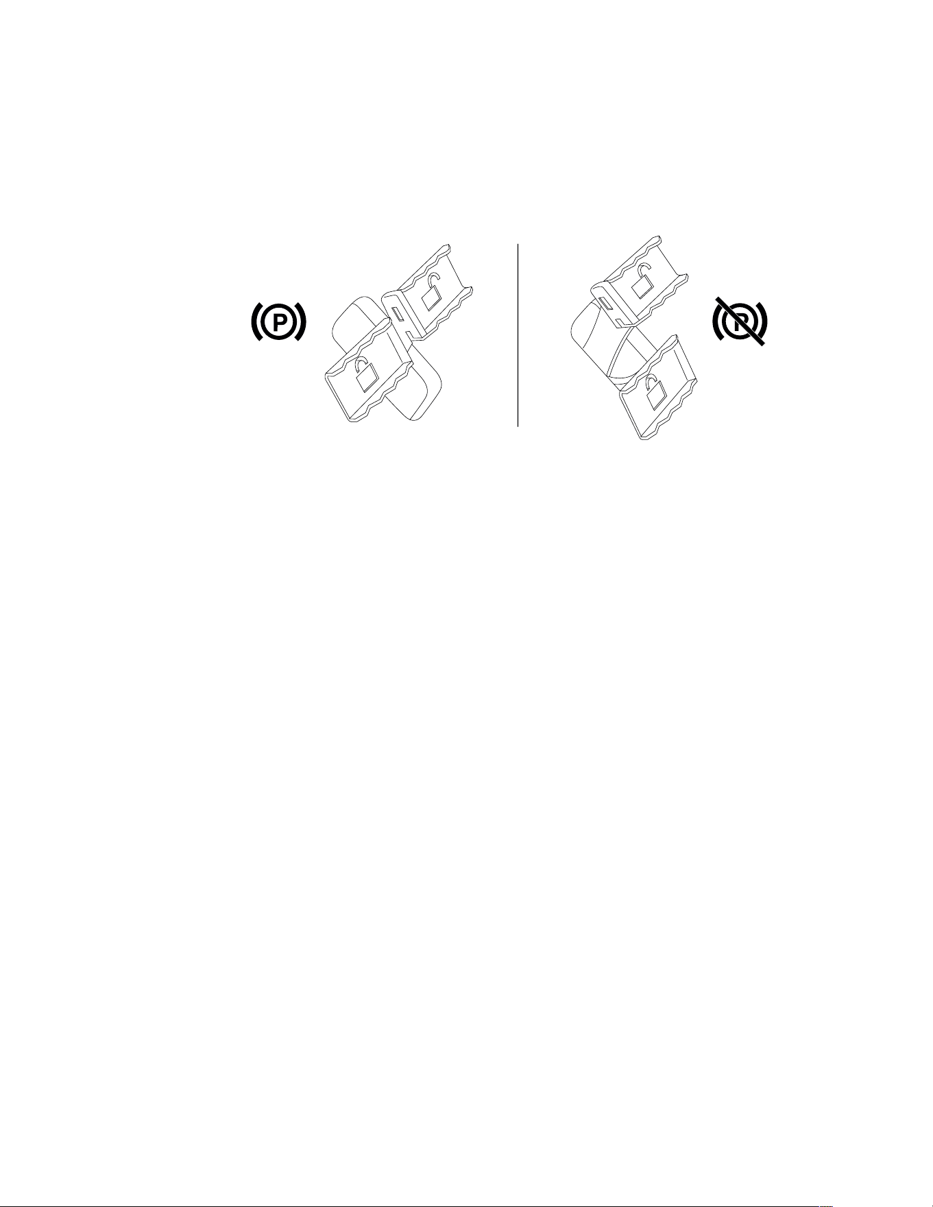
Parking Brake................................................................................................................................ 3–4
Chapter 4: Operation ........................................................................................................................... 4–1
Before Operation .............................................................................................................................. 4–1
Before Operation Safety ............................................................................................................. 4–1
Fuel .................................................................................................................................................. 4–3
Using the Rollover-Protection System (ROPS)..................................................................... 4–4
Safety-Interlock System.............................................................................................................. 4–5
Performing Daily Maintenance.................................................................................................. 4–7
Break-In Time ................................................................................................................................ 4–7
Positioning the Seat..................................................................................................................... 4–8
Adjusting the Motion-Control Lever Tilt ................................................................................... 4–8
During Operation .............................................................................................................................. 4–9
During Operation Safety ............................................................................................................. 4–9
Starting the Engine..................................................................................................................... 4–13
Shutting off the Engine.............................................................................................................. 4–13
Driving the Machine ................................................................................................................... 4–14
Operating the PTO Switch........................................................................................................ 4–16
Side Discharge............................................................................................................................ 4–16
Adjusting the Height of Cut....................................................................................................... 4–17
Using the Transport Lock.......................................................................................................... 4–17
Towing a Trailer........................................................................................................................... 4–17
Operating Tips............................................................................................................................. 4–18
After Operation................................................................................................................................ 4–19
After Operation Safety............................................................................................................... 4–19
Cleaning the Machine................................................................................................................ 4–20
Hauling the Machine .................................................................................................................. 4–20
Chapter 5: Maintenance ..................................................................................................................... 5–1
Maintenance Safety ......................................................................................................................... 5–1
Recommended Maintenance Schedule...................................................................................... 5–3
Pre-Maintenance Procedures ....................................................................................................... 5–4
Moving a Non-Functioning Machine ........................................................................................ 5–4
Lubrication.......................................................................................................................................... 5–5
Greasing the Machine ................................................................................................................. 5–5
Engine Maintenance........................................................................................................................ 5–6
© 2025—Spartan Mowers
1525 White Drive
Batesville, AR 72501
Contact us at joinspartannation.com
Printed in the USA
All rights reserved

Engine Safety ................................................................................................................................ 5–6
Servicing the Air Cleaner ............................................................................................................ 5–6
Engine Oil Service........................................................................................................................ 5–7
Servicing the Spark Plugs .......................................................................................................... 5–8
Fuel Maintenance............................................................................................................................. 5–8
Replacing the Fuel Filter............................................................................................................. 5–8
Electrical System Maintenance..................................................................................................... 5–9
Electrical System Safety............................................................................................................. 5–9
Battery Service.............................................................................................................................. 5–9
Replacing the Fuses .................................................................................................................. 5–14
Drive System Maintenance .......................................................................................................... 5–15
Checking the Seat Belt.............................................................................................................. 5–15
Checking the Tire Pressure...................................................................................................... 5–15
Belt Maintenance............................................................................................................................ 5–15
Inspecting the Belts.................................................................................................................... 5–15
Replacing the Mower-Deck Belt.............................................................................................. 5–15
Replacing the Pump-Drive Belt............................................................................................... 5–16
Hydraulic System Maintenance .................................................................................................. 5–17
Hydraulic System Safety........................................................................................................... 5–17
Hydraulic-Fluid Specifications ................................................................................................. 5–17
Checking the Hydraulic Fluid for RZ-HD, RZ-XD, RT-HD, and SRT XDe
Machines ...................................................................................................................................... 5–17
Checking the Hydraulic Fluid for RT-Pro and SRT XD Machines................................... 5–18
Changing the Hydraulic Fluid .................................................................................................. 5–19
Mower-Deck Maintenance ........................................................................................................... 5–19
Blade Safety ................................................................................................................................ 5–19
Blade Service .............................................................................................................................. 5–19
Leveling the Mower Deck ......................................................................................................... 5–23
Cleaning............................................................................................................................................ 5–26
Disposing of Waste .................................................................................................................... 5–26
Chapter 6: Storage............................................................................................................................... 6–1
Storage Safety .................................................................................................................................. 6–1
Preparing the Machine for Storage Over 30 Days.................................................................... 6–1
Chapter 7: Troubleshooting ............................................................................................................... 7–1
Evaporative Emission Control Warranty Statement
3473-292 B
Chapter 1
Introduction
Intended Use
This rotary-blade, riding lawn mower is intended to be used by professional, hired operators.
It is designed primarily for cutting grass on well-maintained lawns on residential or
commercial properties. Using this product for purposes other than its intended use could
prove dangerous to you and bystanders.
Read this information carefully to learn how to operate and maintain your product properly
and to avoid injury and product damage. You are responsible for operating the product
properly and safely.
Getting Help
G467018
Visit www.spartanmowers.com for product safety
and operation training materials, specifications,
accessory information, help finding a dealer, or to
register your product.
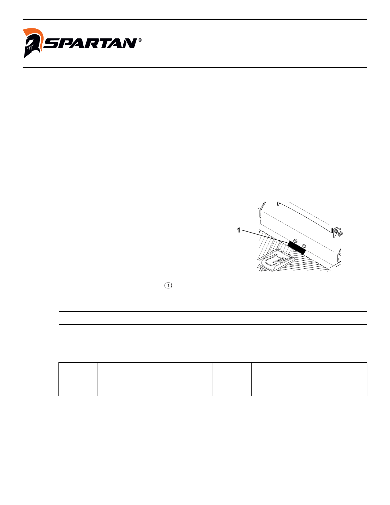
Whenever you need service, genuine Spartan
parts, or additional information, contact an
Authorized Service Dealer or Spartan Customer
Service and have the model and serial numbers of
your product ready. These numbers are located on
the serial plate on your product
. Write the
numbers in the space provided.
IMPORTANT
With your mobile device, you can scan the QR code on the serial number decal (if
equipped) to access warranty, parts, and other product information.
Model
Number:
Serial
Number:
Introduction Page 1–1 3473-292 B

Safety-Alert Symbol
The safety-alert symbol shown in this manual and on the machine identifies important safety
messages that you must follow to prevent accidents.
G405934
DANGER indicates an imminently hazardous situation which, if not avoided, will result in
death or serious injury.
WARNING indicates a potentially hazardous situation which, if not avoided, could result in
death or serious injury.
CAUTION indicates a potentially hazardous situation which, if not avoided, may result in
minor or moderate injury.
This manual uses 2 other words to highlight information. Important calls attention to special
mechanical information and Note emphasizes general information worthy of special
attention.
3473-292B Page 1–2 Introduction: Safety-Alert Symbol

Chapter 2
Safety
General Safety
This product is capable of amputating hands and feet and of throwing objects. Always follow
all safety instructions to avoid serious personal injury or death.
• Read, understand, and follow the instructions and warnings in this Operator’s Manual
and on the machine, engine, and attachments before starting the engine.
• Do not allow children or untrained people to operate or service the machine. Allow only
people who are responsible, trained, familiar with the instructions, and physically capable
to operate or service the machine.
• Keep bystanders, particularly children, away from the operating area.
• Do not operate the machine near drop-offs, ditches, embankments, water, or other
hazards, or on slopes greater than 15°.
• Do not put your hands or feet near moving parts.
• Do not operate the machine without all safety shields, guards, switches, and other
devices in place and working properly.
• Park the machine on a level surface, disengage the drives, engage the parking brake,
shut off the engine, remove the key, and wait for all moving parts to stop before leaving
the operator’s position.
• Wait for the machine to cool before servicing, adjusting, fueling, cleaning, or storing it.
Safety Page 2–1 3473-292 B
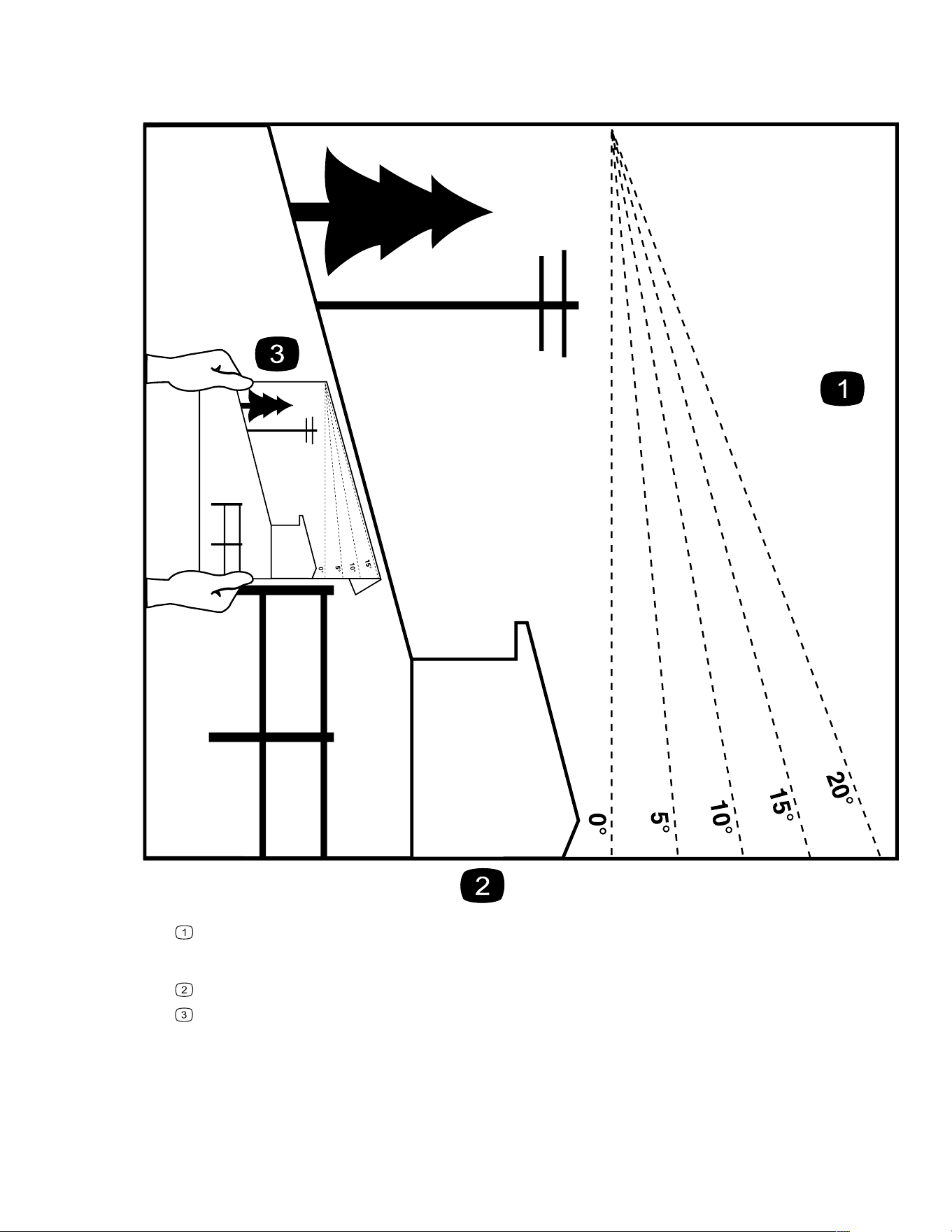
Slope Indicator
You may copy this page for personal use.
G011841s
The maximum slope you can operate the machine on is 15 degrees. Use the slope chart to determine the degree
of slope of hills before operating. Do not operate this machine on a slope greater than 15 degrees. Fold along
the appropriate line to match the recommended slope.
Align this edge with a vertical surface, a tree, building, fence pole, etc.
Example of how to compare slope with folded edge
3473-292B Page 2–2 Safety: Slope Indicator
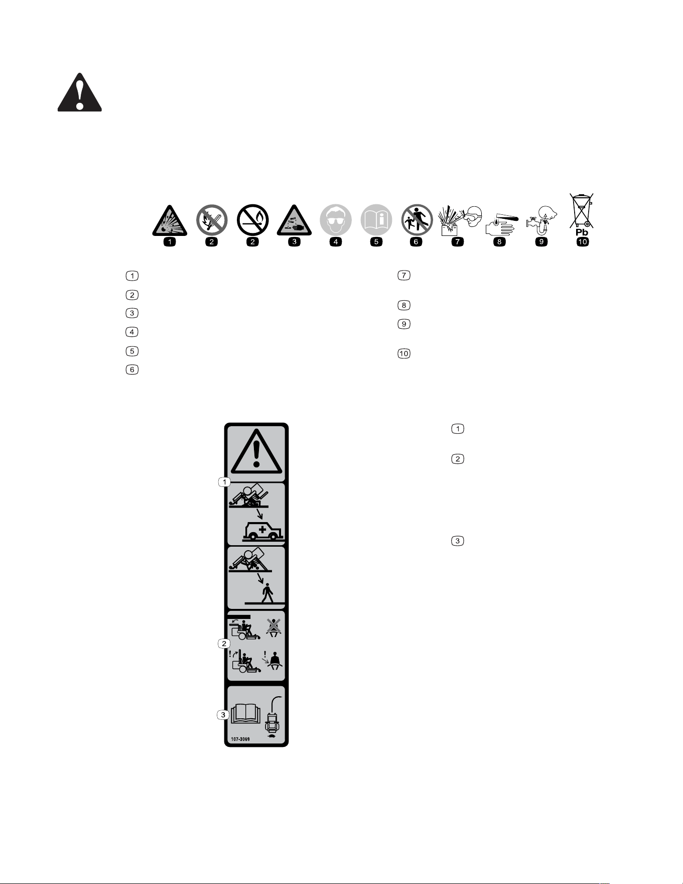
Safety and Instructional Decals
Safety decals and instructions are easily visible to the operator and are located near any area
of potential danger. Replace any decal that is damaged or missing.
Battery Symbols
Some or all of these symbols are on your battery.
s_batterysymbols2
Explosion hazard
No fire, open flame, or smoking
Caustic liquid/chemical burn hazard
Wear eye protection.
Read the Operator’s Manual.
Keep bystanders away from the battery.
Wear eye protection; explosive gases can cause
blindness and other injuries.
Battery acid can cause blindness or severe burns.
Flush eyes immediately with water and get
medical help fast.
Contains lead; do not discard
Decal Part: 107-3069
s_decal107-3069
Warning—there is no rollover
protection when the roll bar is down.
To avoid injury or death from a
rollover accident, keep the roll bar in the
fully raised and locked position and
wear the seat belt. Lower the roll bar
only when absolutely necessary; do not
wear the seat belt when the roll bar is
down.
Read the Operator's Manual; drive
slowly and carefully.
Safety: Safety and Instructional Decals Page 2–3 3473-292 B
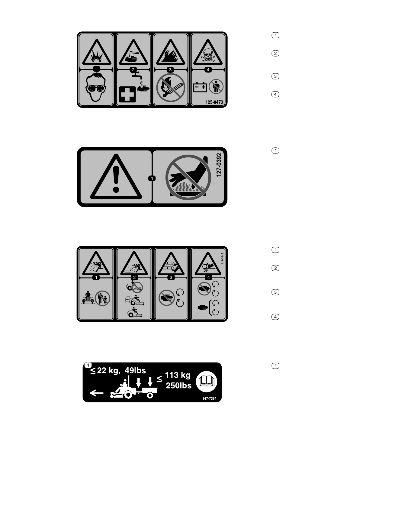
Decal Part: 125-8473
s_decal125-8473
Explosion hazard—wear eye
protection.
Caustic liquid/chemical burn
hazard—rinse affected area and seek
medical assistance.
Fire hazard—keep open flames
away.
Poison hazard—do not tamper with
the battery.
Decal Part: 127-0392
s_decal127-0392
Warning—stay away from hot
surfaces.
Decal Part: 132-0872
s_decal132-0872
Thrown object hazard—keep
bystanders away.
Thrown object hazard, mower—do
not operate the machine with an open
deck; use a bagger or a deflector.
Cutting/dismemberment hazard of
hands or feet, mower blade—stay away
from moving parts.
Entanglement hazard of hands,
belt—stay away from moving parts;
keep all guards and shields in place.
Decal Part: 147-7364
s_decal147-7364
Do not exceed a tongue weight of
22 kg (49 lb); do not exceed a gross
towing weight of 113 kg (250 lb); read
the Operator’s Manual.
3473-292B Page 2–4 Safety: Safety and Instructional Decals
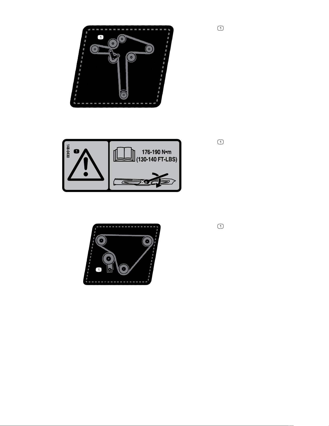
Decal Part: 148-0260
decal148-0260
Belt routing
Decal Part: 148-0430
s_decal148-0430
Warning—read the Operator's
Manual for instructions on torquing the
blade bolt/nut to 176 to 190 N∙m (130 to
140 ft-lb).
Decal Part: 148-0466
decal148-0466
Belt routing
Safety: Safety and Instructional Decals Page 2–5 3473-292 B
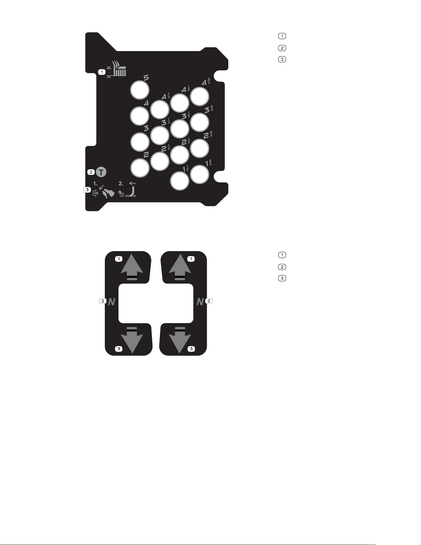
Decal Part: 148-1036
s_decal148-1036
Height of cut (inches)
Transport position
To unlock the deck from the
transport position—push the deck-lift
pedal fully forward, then push the
transport lock lever forward.
Decal Part: 148-1056
s_decal148-1056
Forward
Neutral
Reverse
3473-292B Page 2–6 Safety: Safety and Instructional Decals
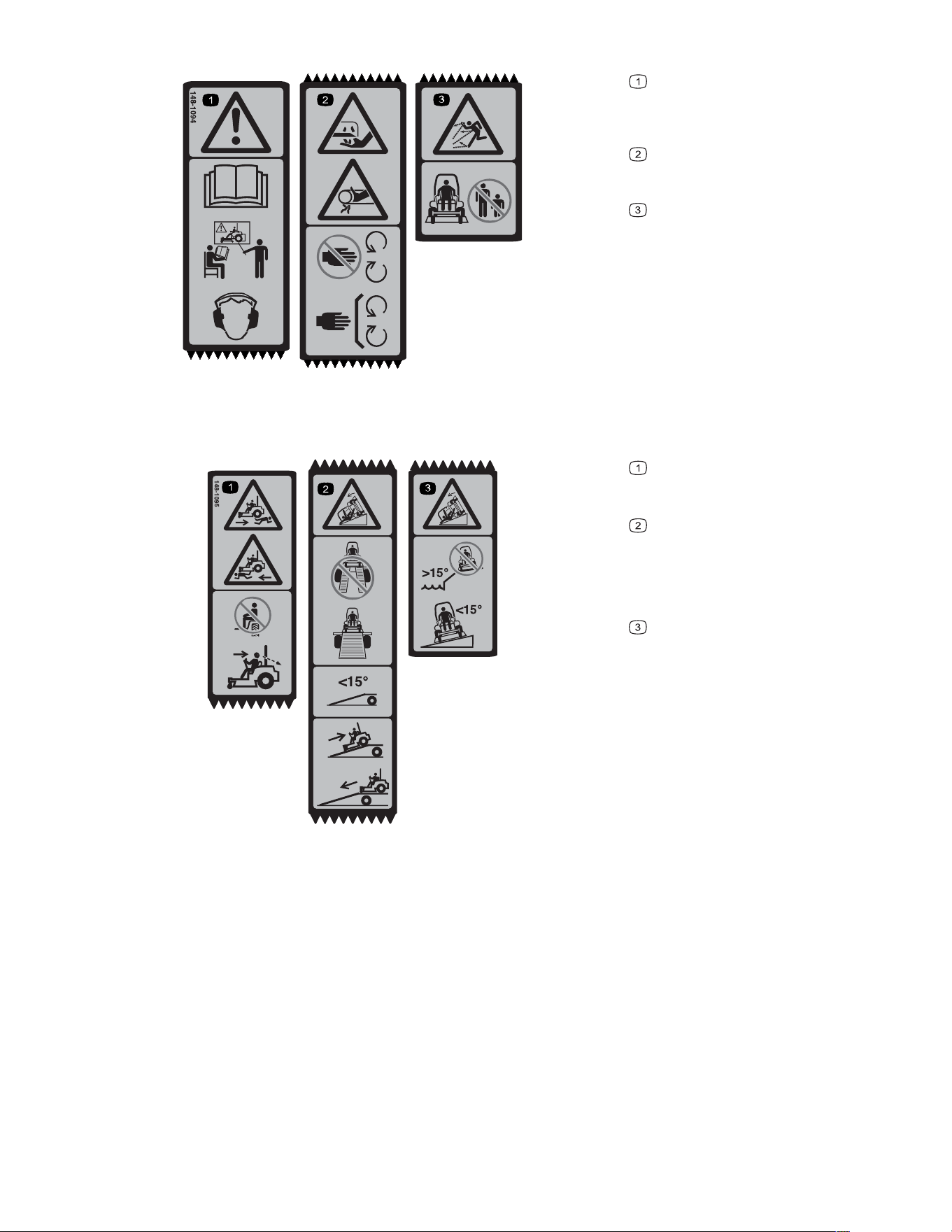
Decal Part: 148-1094
s_decal148-1094
Warning—read the Operator’s
Manual. Do not operate this machine
unless you are trained. Wear hearing
protection.
Cutting and pinching hazard—keep
hands and feet away from moving parts;
keep all guards and shields in place.
Thrown object hazard—keep
bystanders away.
Decal Part: 148-1095
s_decal148-1095
Bodily harm hazard—Do not carry
passengers. Look behind you and down
when mowing in reverse.
Ramp hazard—when loading onto
a trailer, do not use dual ramps; only
use a singular ramp wide enough for the
machine and that has an incline less
than 15 degrees; back up the ramp (in
reverse) and drive forward off the ramp.
Tipping hazard on slopes—Do not
use on slopes near open water; Do not
use on slopes greater than 15 degrees.
Safety: Safety and Instructional Decals Page 2–7 3473-292 B
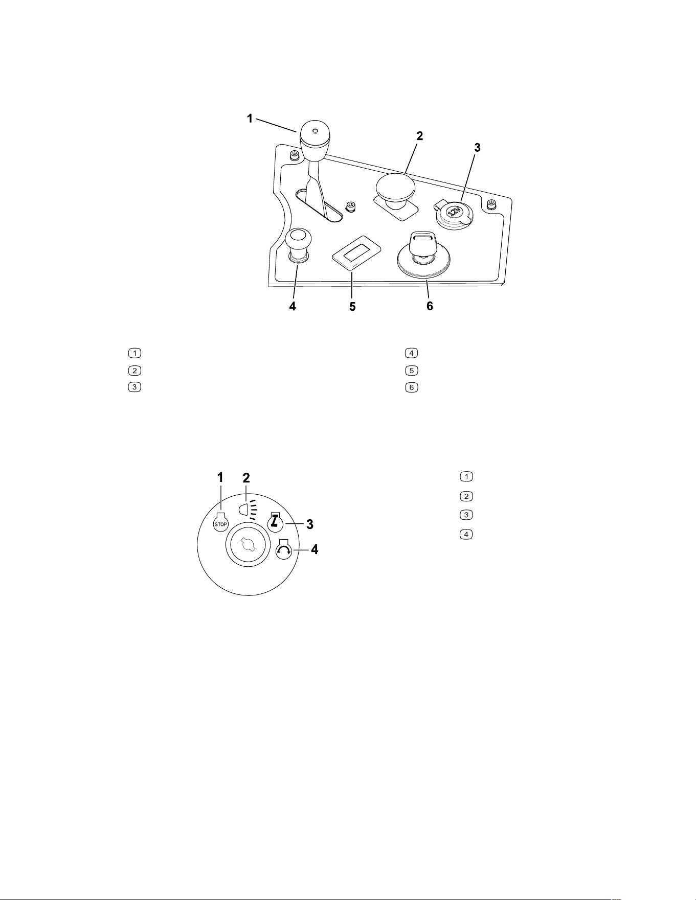
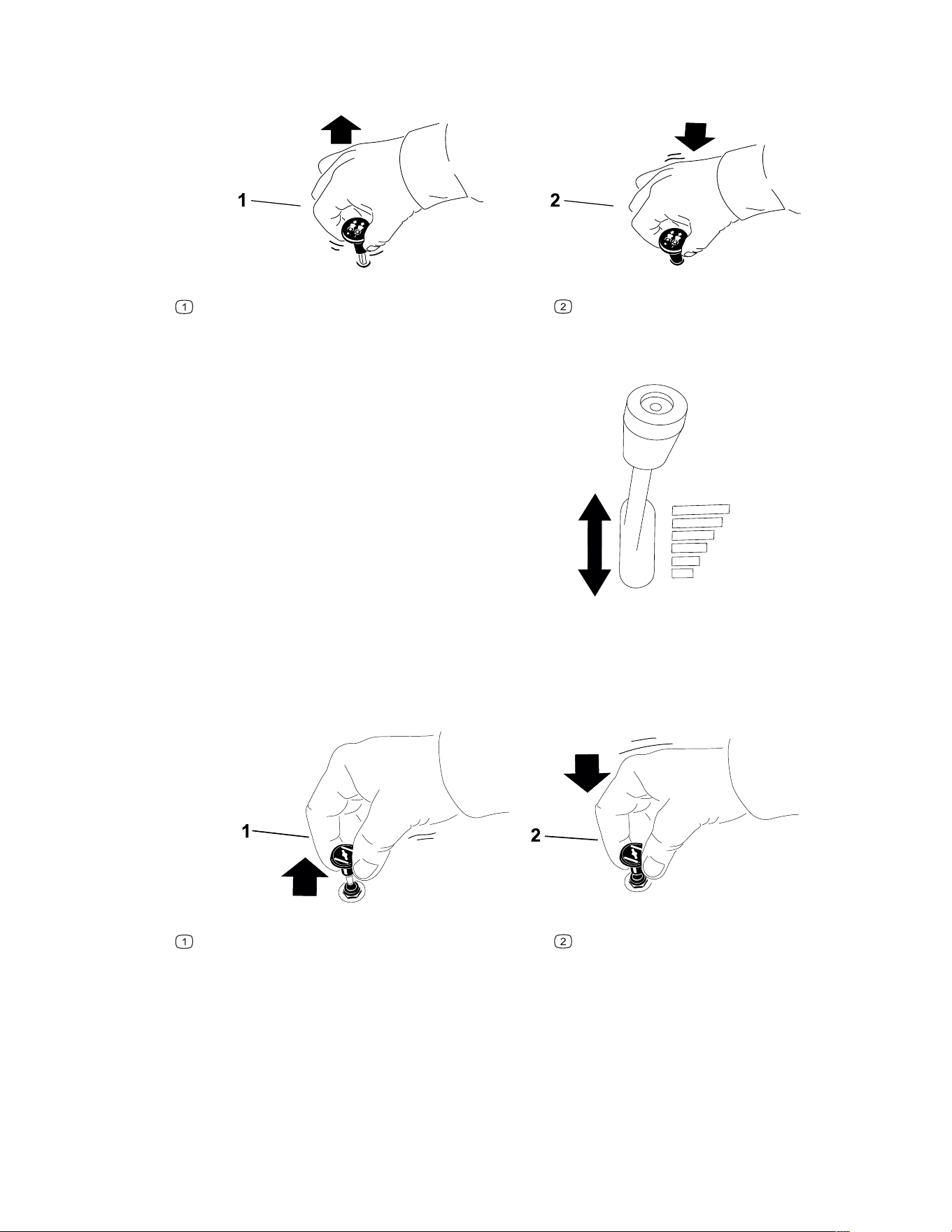
Power-Takeoff (PTO) Switch
The power-takeoff (PTO) switch engages and disengages power to the mower blades.
G442765
Engaged
Disengaged
Throttle Control
G446465
The throttle controls the engine speed, and it has a
continuous-variable setting from the S
LOW to FAST
position.
Choke Control
Use the choke control to aid in starting a cold engine.
G419508
Engaged
Disengaged
Hour meter
The hour meter records the number of hours the engine has been running. It displays the
hours while the engine is off. Use these times for scheduling regular maintenance.
When the engine is running, the hour meter displays the engine RPM.
Product Overview: Controls Page 3–3 3473-292 B

Chapter 4
Operation
Determine the left and right sides of the machine from the normal operating position.
Before Operation
Before Operation Safety
• Do not allow children or untrained people to operate or service the machine. Local
regulations may restrict the age of the operator. The owner is responsible for training all
operators and mechanics.
• Inspect the area where you will use the machine and remove all objects that could be
thrown or could interfere with the operation of the machine.
• Evaluate the terrain to determine the appropriate equipment and any attachments or
accessories required to operate the machine properly and safely.
• Do not carry passengers on the machine.
• Become familiar with the safe operation of the equipment, operator controls, and safety
signs.
• Check that operator-presence controls, safety switches, and guards are attached and
working properly. Do not operate the machine unless they are functioning properly.
• Wear appropriate clothing, including eye protection; long pants; substantial, slip-resistant
footwear; and hearing protection. Tie back long hair and do not wear loose clothing or
loose jewelry.
• Do not operate the machine unless all guards and safety devices, such as the deflectors
and the entire grass catcher, are in place and functioning properly. Replace worn or
deteriorated parts when necessary.
• Shut off the engine, remove the key, and wait for all moving parts to stop before leaving
the operator’s position. Wait for the machine to cool before servicing, adjusting, fueling,
cleaning, or storing it.
WARNING
Contacting the blade can result in serious personal injury.
When you shut off the engine, the blade(s) should stop. If not, stop using your
machine immediately and contact an Authorized Service Dealer.
• Before mowing, inspect the machine to ensure that the cutting assemblies are working
properly.
Operation Page 4–1 3473-292 B

Before Operation Safety (continued)
• Keep bystanders, particularly children, and pets away from the machine during
operation. Shut off the machine and attachment(s) if anyone enters the area.
Fuel Safety
• Fuel is extremely flammable and highly explosive. A fire or explosion from fuel can burn
you and others and can damage property.
– To prevent a static charge from igniting the fuel, place the container and/or machine
directly on the ground before filling, not in a vehicle or on an object.
– Fill the fuel tank outdoors on level ground, in an open area, and when the engine is
cold. Wipe up any fuel that spills.
– Do not handle fuel when smoking or around an open flame or sparks.
– Do not remove the fuel cap or add fuel to the tank while the engine is running or hot.
– If you spill fuel, do not attempt to start the engine. Avoid creating a source of ignition
until the fuel vapors have dissipated.
– Store fuel in an approved container and keep it out of the reach of children.
• Do not overfill the fuel tank. Replace the fuel cap and tighten it securely.
• In certain conditions during fueling, static electricity can be released, causing a spark that
can ignite fuel vapors.
• Do not fill containers inside a vehicle or on a truck or trailer bed with a plastic liner.
Always place containers on the ground and away from your vehicle before filling.
• Remove the equipment from the truck or trailer and refuel it while it is on the ground. If
this is not possible, then refuel from a portable container rather than from a fuel-
dispenser nozzle.
• Keep the fuel-dispenser nozzle in contact with the rim of the fuel tank or container
opening at all times until fueling is complete. Do not use a nozzle lock-open device.
• Fuel is harmful or fatal if swallowed. Long-term exposure to vapors can cause serious
injury and illness.
– Avoid prolonged breathing of vapors.
– Keep your hands and face away from the nozzle and the fuel-tank opening.
– Keep fuel away from your eyes and skin.
• Clean up any spilled fuel.
• Do not store the machine or fuel container where there is an open flame, spark, or pilot
light, such as on a water heater or on other appliances.
• Do not operate the machine without the entire exhaust system in place and in proper
working condition.
3473-292B Page 4–2 Operation: Before Operation

Fuel
Fuel Specifications
Capacity 43.2 L (9.5 US gallons)
Type Unleaded gasoline
Minimum octane rating 87 (US) or 91 (research octane; outside the US)
Ethanol No more than 10% by volume
Methanol None
MTBE (methyl tertiary butyl ether) Less than 15% by volume
Oil Do not add to the fuel
Use only clean, fresh (no more than 30 days old), fuel from a reputable source.
IMPORTANT
To reduce starting problems, add fuel stabilizer/conditioner to fresh fuel as directed
by the fuel-stabilizer/conditioner manufacturer.
Filling the Fuel Tank
1. Park the machine on a level surface, disengage the PTO switch, move the motion-
control levers to the N
EUTRAL-LOCK position, and engage the parking brake.
2. Shut off the engine, remove the key, and wait for all moving parts to stop before leaving
the operating position.
3. Clean around the fuel-tank cap.
4. Fill the fuel tank to the bottom of the filler neck. Do not fill the fuel tank completely full.
Operation: Before Operation Page 4–3 3473-292 B
Using the Rollover-Protection System (ROPS)
WARNING
To avoid injury or death from rollover: keep the roll bar in the fully raised, locked
position and use the seat belt.
Ensure that the seat is secured to the machine.
WARNING
There is no rollover protection when the roll bar is in the down position.
• Lower the roll bar only when absolutely necessary.
• Do not wear the seat belt when the roll bar is in the down position.
• Drive slowly and carefully.
• Raise the roll bar as soon as clearance permits.
• Check carefully for overhead clearances (i.e., branches, doorways, electrical
wires) before driving under any objects, and do not contact them.
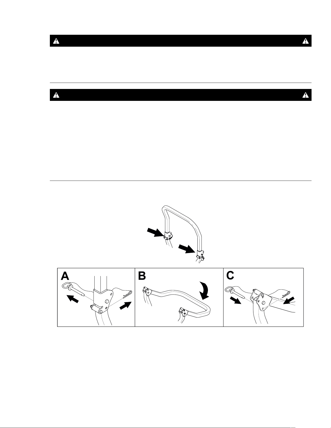
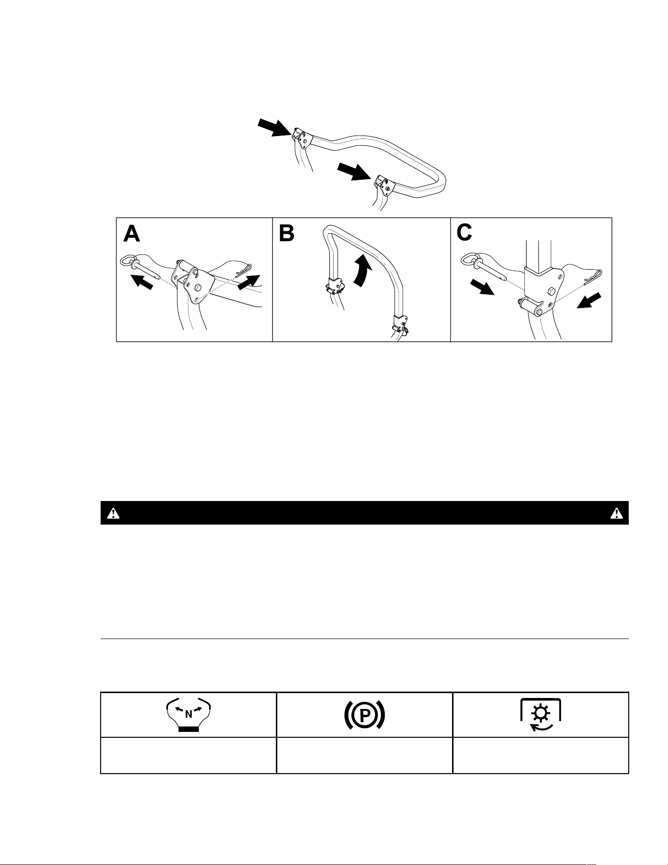
Lowering the Roll Bar
G515235
1. Remove the hairpin cotters and pin from both sides of the roll bar.
2. Lower the roll bar.
3. Install the 2 pins and secure them with the hairpin cotters.
3473-292B Page 4–4 Operation: Before Operation
Using the Rollover-Protection System (ROPS)
(continued)
Raising the Roll Bar
G515236
1. Remove the hairpin cotters and pin from both sides of the roll bar.
2. Raise the roll bar.
3. Install the 2 pins and secure them with the hairpin cotters.
Safety-Interlock System
DANGER
If safety-interlock switches are disconnected or damaged, the machine could operate
unexpectedly, which will result in serious injury or death.
• Do not tamper with the interlock switches.
• Check the operation of the interlock switches daily, and replace any damaged
switches before operating the machine.
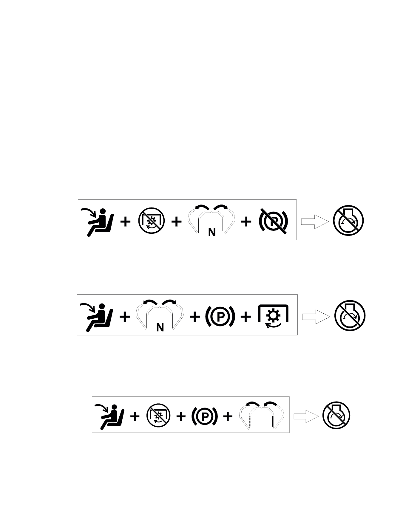
The safety-interlock system prevents the engine from starting unless the conditions in the
table occur:
The motion-control levers are
in the N
EUTRAL position.
The parking brake is engaged. The PTO is disengaged.
Operation: Before Operation Page 4–5 3473-292 B
Safety-Interlock System (continued)
The safety-interlock system also shuts off the engine when the following occurs:
• You rise from the seat when the PTO is engaged.
• You rise from the seat when the motion-control levers are not in the N
EUTRAL-LOCK position
or the parking brake is disengaged.
• You engage the parking brake when the motion-control levers are not in the N
EUTRAL-
L
OCK position.
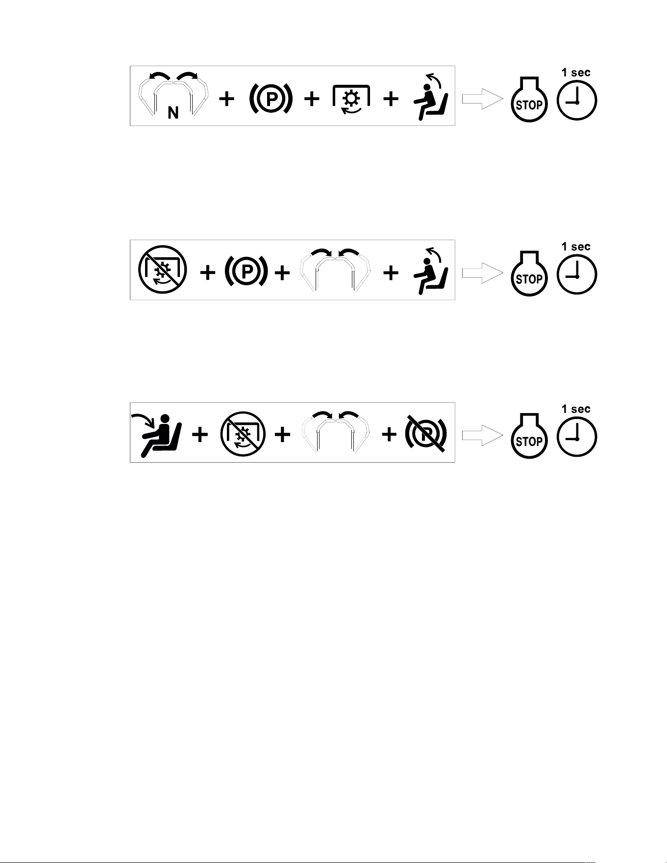
Testing the Safety-Interlock System
Test the safety-interlock system before you use the machine each time. If the safety system
does not operate as described below, have an Authorized Service Dealer repair the safety
system immediately.
1. Sit on the seat, move the blade-control switch to the O
FF position, move the motion-
control levers to the N
EUTRAL-LOCK position, and disengage the parking brake. Try
starting the engine; the engine should not crank.
G515243
2. Sit on the seat, move the motion-control levers to the NEUTRAL-LOCK position, engage the
parking brake, and move the blade-control switch to the O
N position. Try starting the
engine; the engine should not crank.
G466910s
3. Sit on the seat, move the blade-control switch to the OFF position, and engage the
parking brake. Move either motion-control lever to the center, unlocked position. Try
starting the engine; the engine should not crank. Repeat with the other motion-control
lever.
G515257
4. Sit on the seat, move the blade-control switch to the OFF position, move the motion-
control levers to the N
EUTRAL-LOCK position, and engage the parking brake. Start the
engine. While the engine is running, engage the blade-control switch and rise slightly
from the seat; the engine should shut off within 1 second.
3473-292B Page 4–6 Operation: Before Operation
Safety-Interlock System (continued)
G515256
5. Sit on the seat, move the blade-control switch to the OFF position, move the motion-
control levers to the N
EUTRAL-LOCK position, and engage the parking brake. Start the
engine. While the engine is running, move the motion-control levers to the center,
unlocked position and rise slightly from the seat; the engine should shut off within 1
second.
G515255
6. Sit on the seat, move the blade-control switch to the OFF position, move the motion-
control levers to the N
EUTRAL-LOCK position, and engage the parking brake. While the
engine is running, move the motion-control levers to the center, unlocked position and
engage the parking brake; the engine should shut off within 1 second.
G515242
Performing Daily Maintenance
Before starting the machine each day, perform the Each Use/Daily procedures listed in the
Maintenance Schedule.
Break-In Time
New engines take time to develop full power. Mower decks and drive systems have higher
friction when new, placing additional load on the engine. Allow 40 to 50 hours of break-in
time for new machines to develop full power and best performance.
Operation: Before Operation Page 4–7 3473-292 B
Positioning the Seat
G419351
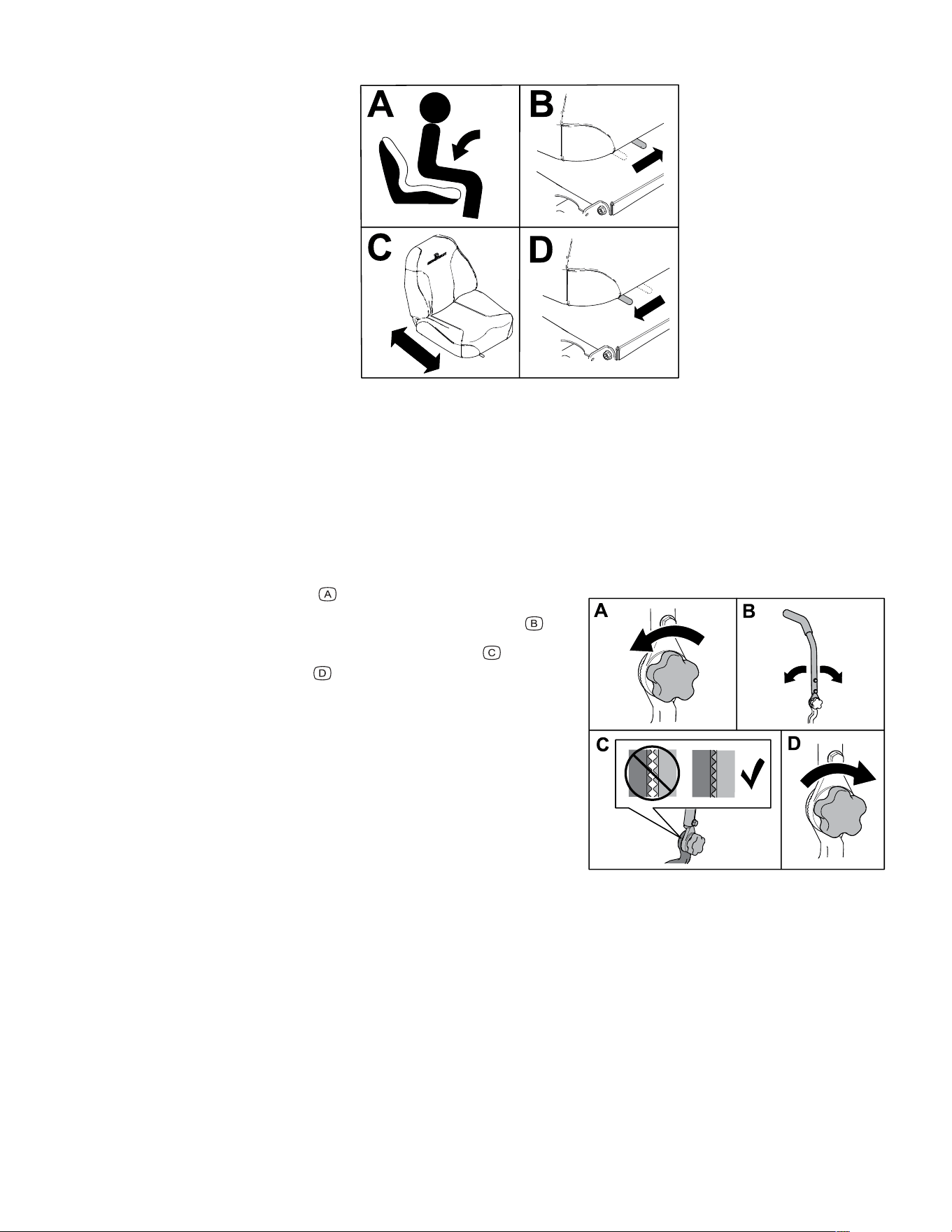
Adjusting the Motion-Control Lever Tilt
Machines with Soft-Knob Adjustable Arms Only
1. Park the machine on a level surface, disengage the PTO switch, move the motion-
control levers to the N
EUTRAL-LOCK position, and engage the parking brake.
2. Shut off the engine, remove the key, and wait for all moving parts to stop before making
adjustments.
G535100
3. Loosen the knob .
4. Pivot the control lever forward or rearward
.
5. Ensure that the teeth are fully seated
and
tighten the knob
.
6. Move the lever through the full range of motion
several times to ensure that the lever is
adjusted properly and is secure.
7. Repeat the adjustment for the other control
lever; ensure that the levers are even in the
neutral position.
3473-292B Page 4–8 Operation: Before Operation

During Operation
During Operation Safety
• The owner/operator can prevent and is responsible for accidents that may cause
personal injury or property damage.
• Use your full attention while operating the machine. Do not engage in any activity that
causes distractions; otherwise, injury or property damage may occur.
• Do not operate the machine while ill, tired, or under the influence of alcohol or drugs.
• Do not operate the machine unless all guards and safety devices, such as the deflectors
and the entire grass catcher, are in place and functioning properly. Replace worn or
deteriorated parts with genuine Spartan parts when necessary.
• Operating engine parts, especially the muffler, can become extremely hot. Severe burns
can occur on contact and debris, such as leaves, grass, brush, etc. can catch fire. Keep
the engine area free from debris and excessive oil and grease.
• Operate the engine only in well-ventilated areas. Exhaust gases contain carbon
monoxide, which is lethal if inhaled.
• Operate the machine only in good visibility and appropriate weather conditions. Do not
operate the machine when there is the risk of lightning.
• Start the engine with your feet well away from the blades.
• Keep your hands and feet away from moving parts. Keep clear of the discharge opening.
• Keep away from holes, ruts, bumps, rocks, and other hazards. Use care when
approaching blind corners, shrubs, trees, tall grass or other objects that may hide
obstacles or obscure your view.
• Do not mow with the discharge deflector raised, removed, or altered unless there is a
grass-collection system or mulch kit in place and working properly.
• Do not mow in reverse unless it is absolutely necessary. Always look down and behind
you before moving the machine in reverse.
• Stop the blades whenever you are not mowing. Slow down the machine, and use caution
when crossing surfaces other than grass or when transporting the machine to and from
the operating area.
• Be aware of the mower discharge path and direct the discharge away from others. Avoid
discharging material against a wall or obstruction because the material may ricochet
back toward you.
• If the machine strikes an object or starts to vibrate, immediately shut off the engine,
remove the key, and wait for all moving parts to stop before examining the machine for
damage. Make all necessary repairs before resuming operation.
• Slow down and use caution when making turns and crossing roads and sidewalks with
the machine. Always yield the right-of-way.
• Never leave a running machine unattended.
• Before you leave the operating position, do the following:
– Park the machine on a level surface.
– Disengage the power takeoff and lower the attachments.
Operation: During Operation Page 4–9 3473-292 B

During Operation Safety (continued)
– Engage the parking brake.
– Shut off the engine and remove the key.
– Wait for all moving parts to stop.
• Never carry children on the machine.
• Do not carry children on the machine, even when the blades are not moving. Children
could fall off and be seriously injured or prevent you from safely operating the machine.
Children who have been given rides in the past could appear in the operating area
without warning and be run over or backed over by the machine.
• Children are often attracted to the machine and the mowing activity. Never assume that
children will remain where you last saw them.
• Keep children out of the operating area and under the watchful care of a responsible
adult other than the operator.
• Be alert and shut off the machine if children enter the operating area.
• Before backing up or turning the machine, look down and all around for small children.
• Do not use the machine as a towing vehicle unless it has a hitch installed. Attach towed
equipment to the machine only at the hitch point.
• Use only accessories and attachments approved by Spartan Mowers.
Rollover Protection System (ROPS) Safety
• The ROPS is an integral safety device. Do not remove any of the ROPS components
from the machine.
• Ensure that the seat belt is attached and that you can release it quickly in an emergency.
• Keep the roll bar in the fully raised and locked position and always wear your seat belt
whenever the roll bar is up.
• Check carefully for overhead objects before you drive under them, and do not contact
them.
• Replace damaged ROPS components. Do not repair or alter them.
• There is no rollover protection when the roll bar is down.
• Wheels dropping over edges, over steep banks, or into water can cause a rollover, which
may result in serious injury or death.
• Do not wear the seat belt when the roll bar is down.
• Lower the roll bar only when absolutely necessary; raise it as soon as clearance permits.
• In the event of a rollover, take the machine to an Authorized Service Dealer to inspect the
ROPS.
• Use only accessories and attachments for the ROPS approved by Spartan Mowers.
Slope Safety
• Slopes are a major factor related to loss of control and rollover accidents, which can
result in severe injury or death. The operator is responsible for safe slope operation.
3473-292B Page 4–10 Operation: During Operation
During Operation Safety (continued)
Operating the machine on any slope requires extra caution. Before using the machine on
a slope, do the following:
– Review and understand the slope instructions in the manual and on the machine.
– Use an angle indicator to determine the approximate slope angle of the area.
– Never operate on slopes greater than 15°.
– Evaluate the site conditions of the day to determine if the slope is safe for machine
operation. Use common sense and good judgment when performing this evaluation.
Changes in the terrain, such as moisture, can quickly affect the operation of the
machine on a slope.
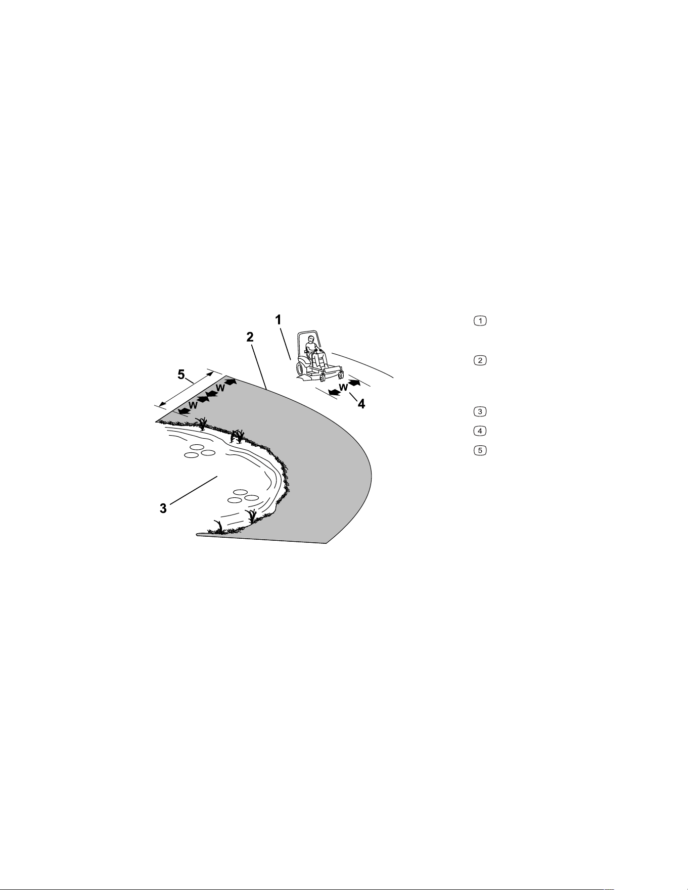
• Identify hazards at the base of the slope. Do not operate the machine near drop-offs,
ditches, embankments, water, or other hazards. The machine could suddenly roll over if
a wheel goes over the edge or the edge collapses. Keep a safe distance (twice the width
of the machine) between the machine and any hazard. Use a walk-behind machine or a
hand trimmer to mow the grass in these areas.
G221745s
Safe Zone—use the machine
here on slopes less than 15° or flat
areas.
Danger Zone—use a walk-
behind mower and/or a hand
trimmer on slopes greater than 15°
and near drop-offs or water.
Water
W = Width of the machine
Keep a safe distance (twice the
width of the machine) between the
machine and any hazard.
• Avoid starting, stopping, or turning the machine on slopes. Avoid making sudden
changes in speed or direction; turn slowly and gradually.
• Do not operate a machine under any conditions where traction, steering, or stability is in
question. Be aware that operating the machine on wet grass, across slopes, or downhill
may cause the machine to lose traction. Loss of traction to the drive wheels may result in
sliding and a loss of braking and steering. The machine can slide even if the drive wheels
are stopped.
• Remove or mark obstacles such as ditches, holes, ruts, bumps, rocks, or other hidden
hazards. Tall grass can hide obstacles. Uneven terrain could overturn the machine.
• Use extra care while operating with accessories or attachments, such as grass-collection
systems. These can change the stability of the machine and cause a loss of control.
Follow directions for counterweights.
• If possible, keep the deck lowered to the ground while operating on slopes. Raising the
deck while operating on slopes can cause the machine to become unstable.
Operation: During Operation Page 4–11 3473-292 B

During Operation Safety (continued)
Towing Safety
• Do not attach towed equipment except at the hitch point.
• Do not use the machine as a towing vehicle unless it has a hitch installed.
• Do not exceed the maximum gross towing weight.
• Never allow children or others near the towed equipment.
• On slopes, the weight of the towed equipment may cause loss of traction, increased risk
of rollover, and loss of control. Reduce the towed weight and slow down.
• The stopping distance may increase with the weight of a towed load. Travel slowly and
allow extra distance to stop.
• Make wide turns to keep the attachment clear of the machine.
3473-292B Page 4–12 Operation: During Operation

Starting the Engine
1. Sit on the seat.
2. Move the motion-control levers outward to the N
EUTRAL-LOCK position.
3. Engage the parking brake.
4. Disengage the PTO switch.
5. Engage the choke control (if applicable).
Note: A warm or hot engine may not require choking.
6. Insert the key into the key switch and turn it to the S
TART position. When the engines
starts, release the key.
IMPORTANT
Do not engage the starter for more than 5 seconds at a time. Engaging the starter
motor for more than 5 seconds can damage the starter motor. If the engine fails to
start, wait 10 seconds before operating the engine starter again.
7. Disengage the choke control (if applicable).
Note: When starting the engine in cold conditions, allow the engine to run for a minute
before disengaging the choke control.
Shutting off the Engine
1. Park the machine on a level surface.
2. Disengage the PTO switch.
3. Move the motion-control levers outward to the N
EUTRAL-LOCK position.
4. Engage the parking brake.
5. Move the throttle control to the S
LOW position.
6. Turn the key to the O
FF position and remove the key.
CAUTION
Children or bystanders may be injured if they move or attempt to operate the machine
while it is unattended.
Always remove the key and engage the parking brake when leaving the machine
unattended.
Operation: During Operation Page 4–13 3473-292 B
Driving the Machine
CAUTION
Positioning one lever too far in front of the other causes the machine to spin very
rapidly. As a result, you may lose control of the machine, causing personal injury to
you and damage to the machine.
Slow down the machine before making sharp turns.
The drive wheels turn independently, powered by motors on each axle. You can turn 1 side
in reverse while you turn the other forward, causing the machine to spin rather than turn.
This greatly improves the machine maneuverability but may require some time for you to
adapt to how it moves.
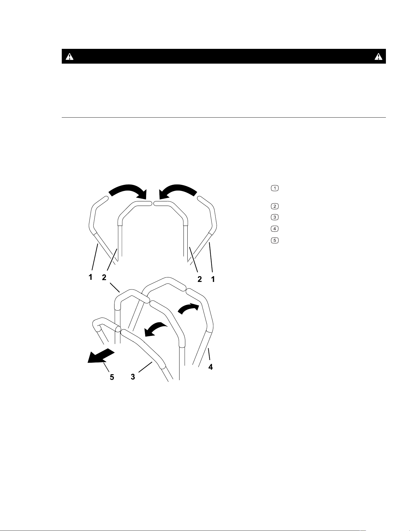
1. Move the motion-control levers down to the center, unlocked position.
G426843s
Motion-control levers—NEUTRAL-
LOCK position
Center, unlocked position
Forward
Reverse
Front of the machine
3473-292B Page 4–14 Operation: During Operation
Driving the Machine (continued)
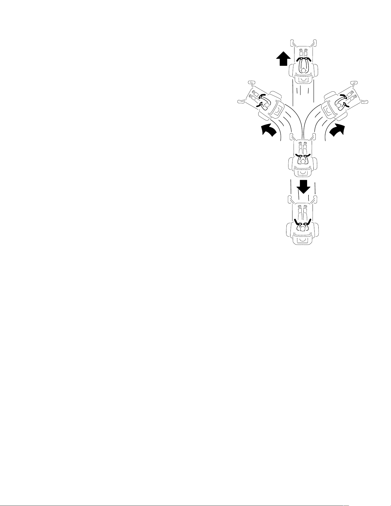
G397314s
2. Slowly push the motion-control levers forward
or rearward. Move 1 lever farther than the
other lever to turn.
Note: The farther you move the motion-
control levers, the faster the machine moves in
that direction.
3. To stop, pull the motion-control levers back to
the N
EUTRAL position.
Operation: During Operation Page 4–15 3473-292 B

Operating the PTO Switch
DANGER
The rotating blades under the mower deck are dangerous. Blade contact will cause
serious injury or death.
Do not put your hands or feet under the mower or mower deck when the blades are
engaged.
DANGER
An uncovered discharge opening allows objects to be thrown toward you or
bystanders. Also, contact with the blade could occur. Thrown objects or blade
contact will cause serious injury or death.
Do not operate the mower with the discharge deflector raised, removed, or altered
unless a grass collection system or mulch kit is in place and working properly.
The PTO switch starts and stops the mower blades and any powered attachments.
1. Increase the throttle to full throttle.
2. Engage the PTO switch.
Note: You may hear a squealing noise as the clutch plates engage. This is normal.
3. Mow as desired.
4. Disengage the PTO switch after mowing.
Side Discharge
The hinged grass deflector disperses clippings to the side and down toward the turf.
DANGER
Without the grass deflector, discharge cover, or complete grass catcher assembly
mounted in place, you and bystanders are exposed to blade contact and thrown
debris. Contact with rotating mower blade(s) and thrown debris will cause injury or
death.
• Do not remove the grass deflector from the machine, because the grass deflector
routes material down toward the turf. If the grass deflector is ever damaged,
replace it immediately.
• Never try to clear the discharge area or mower blades unless the power takeoff
(PTO) is off. Shut off the machine.
3473-292B Page 4–16 Operation: During Operation
Adjusting the Height of Cut
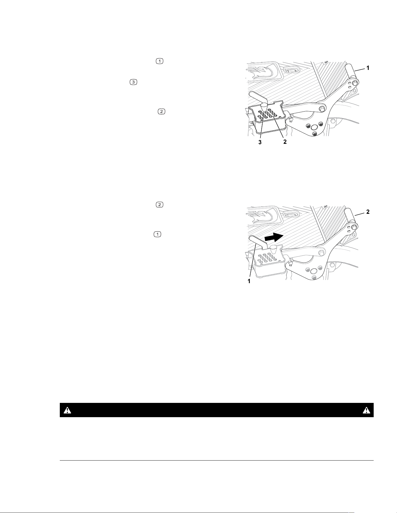
You can adjust the height of cut from 38 to 127 mm (1-1/2 to 5 inches) in 6.4 mm (1/4 inch)
increments.
G514391
1. Push the deck-lift pedal with your foot to
raise the mower deck.
2. Remove the pin
from the height-of-cut
bracket.
3. Insert the pin into the hole corresponding to
the desired height of cut
.
4. Lower the deck slowly until the lever contacts
the pin.
Using the Transport Lock
G514392
1. Push the deck-lift pedal fully forward to lock
the mower deck in the T
RANSPORT position.
2. Push the deck-lift pedal fully forward and push
the transport lock lever
forward to the
U
NLOCK position, then slowly lower the mower
deck to the desired height of cut.
Towing a Trailer
Maximum Gross Towing Weight: 113 kg (250 lb)
Contact an Authorized Service Dealer for the available tow hitches.
Do not exceed 22 kg (49 lb) of tongue weight on the tow hitch of the machine.
When hauling cargo or towing a trailer, do not overload the machine or trailer. Overloading
can cause poor performance or damage to the hydraulic-drive units, tires, and frame.
WARNING
Towing on slopes could reduce the stability of the machine and result in injury or
death.
Tow equipment only on slopes less than 5°.
Operation: During Operation Page 4–17 3473-292 B
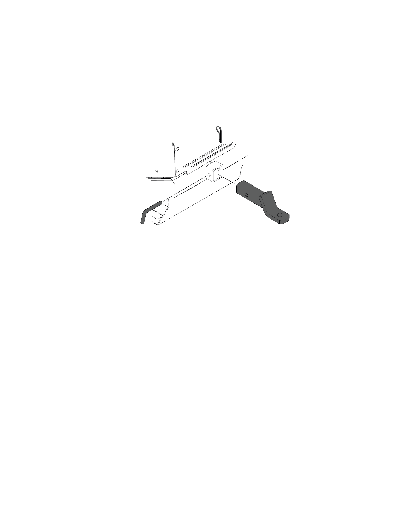
Towing a Trailer (continued)
1. Park the machine on a level surface, disengage the PTO switch, move the motion-
control levers to the N
EUTRAL-LOCK position, and engage the parking brake.
2. Shut off the engine, remove the key, and wait for all moving parts to stop before leaving
the operating position.
3. Insert the hitch ball mount into the receiver located at the rear of the machine.
4. Insert the hitch pin through the hole in the receiver and the hitch ball mount.
5. Secure the hitch using the hairpin cotter.
G436206
Operating Tips
Maximize Air Circulation
For best mowing and maximum air circulation, operate the machine with the throttle in the
F
AST position. Air circulation is required to thoroughly cut grass clippings, so do not set the
height-of-cut so low as to totally surround the mower deck in uncut grass. Always try to have
1 side of the mower deck free from uncut grass, which allows air to be drawn into the mower
deck.
Avoid Cutting Too Low
When mowing uneven ground, raise the cutting height to slightly higher than normal to avoid
scalping the turf. However, the cutting height used in the past is generally the best one to
use. When cutting grass longer than 15 cm (6 inches) tall, you may want to cut the lawn
twice to ensure an acceptable quality of cut.
Cut a Third of the Grass Blade
It is best to cut only about a third of the grass blade. Cutting more than that is not
recommended unless grass is sparse, or it is late fall when grass grows more slowly.
Alternate the Mowing Direction
Alternate the mowing direction to keep the grass standing straight. This also helps disperse
clippings, which enhances decomposition and fertilization.
3473-292B Page 4–18 Operation: During Operation

Operating Tips (continued)
Mowing Frequency
Grass grows at different rates at different times of the year. To maintain the same cutting
height, mow more often in early spring. As the grass growth rate slows in mid summer, mow
less frequently. If you cannot mow for an extended period, first mow at a high cutting height,
then mow again 2 days later at a lower height setting.
Mow at Slower Ground Speeds
In certain conditions, mowing at a slower ground speed can improve cut quality.
Avoid Grass Clumps
If you must stop driving forward while mowing, a clump of grass clippings may drop onto
your lawn. To avoid this, move onto a previously cut area with the blades engaged or
disengage the mower deck while moving forward.
Keep the Underside of the Mower Deck Clean
Clean clippings and dirt from the underside of the mower deck after each use. Grass and dirt
build-up will eventually decrease the cutting quality.
Maintain the Blades
Maintain a sharp blade throughout the cutting season because a sharp blade cuts cleanly
without tearing or shredding the grass blades. Tearing and shredding turns grass brown at
the edges, which slows growth and increases the chance of disease. Check the mower
blades after each use for sharpness, and for any wear or damage. File down any nicks and
sharpen the blades as necessary. If a blade is damaged or worn, replace it.
After Operation
After Operation Safety
• Park the machine on a level surface, disengage the drives, engage the parking brake,
shut off the engine, remove the key, and wait for all moving parts to stop before leaving
the operator’s position.
• Wait for the machine to cool before servicing, adjusting, fueling, cleaning, or storing it.
• Clean grass, leaves, excessive grease and oil, and other debris from the mower deck,
muffler, drives, grass catcher, and engine area to help prevent fires.
• Close the fuel-shutoff valve (if equipped) before storing or transporting the machine.
• Use full-width ramps for loading the machine into a trailer or truck.
• Tie the machine down securely using straps, chains, cable, or ropes. Both front and rear
straps should be directed down and outward from the machine.
Operation: After Operation Page 4–19 3473-292 B

Cleaning the Machine
Clean the machine after each use.
1. Park the machine on a level surface, disengage the PTO switch, move the motion-
control levers to the N
EUTRAL-LOCK position, and engage the parking brake.
2. Shut off the engine, remove the key, and wait for all moving parts to stop before leaving
the operating position.
3. Clean grass and debris from cutting unit, muffler, drives, grass catcher, and engine.
IMPORTANT
You can wash the machine with a mild detergent and water. Do not pressure wash the
machine. Avoid excessive use of water, especially near the control panel, under the
seat, around the engine, hydraulic pumps, and motors.
Hauling the Machine
Use a heavy-duty trailer or truck to haul the machine. Use a full-width ramp. Ensure that the
trailer or truck has all the necessary brakes, lighting, and marking as required by law. Please
carefully read all the safety instructions. Knowing this information could help you or
bystanders avoid injury. Refer to your local ordinances for trailer and tie-down requirements.
WARNING
Driving on the street or roadway without turn signals, lights, reflective markings, or a
slow-moving-vehicle emblem is dangerous and can lead to accidents causing
personal injury.
Do not drive the machine on a public street or roadway.
Trailer Requirements
WARNING
Loading a machine onto a trailer or truck increases the possibility of tip-over and
could cause serious injury or death.
• Use only a full-width ramp; do not use individual ramps for each side of the
machine.
• Do not exceed a 15-degree angle between the ramp and the ground or between the
ramp and the trailer or truck.
• Ensure that the length of ramp is at least 4 times as long as the height of the trailer
or truck bed to the ground.
3473-292B Page 4–20 Operation: After Operation
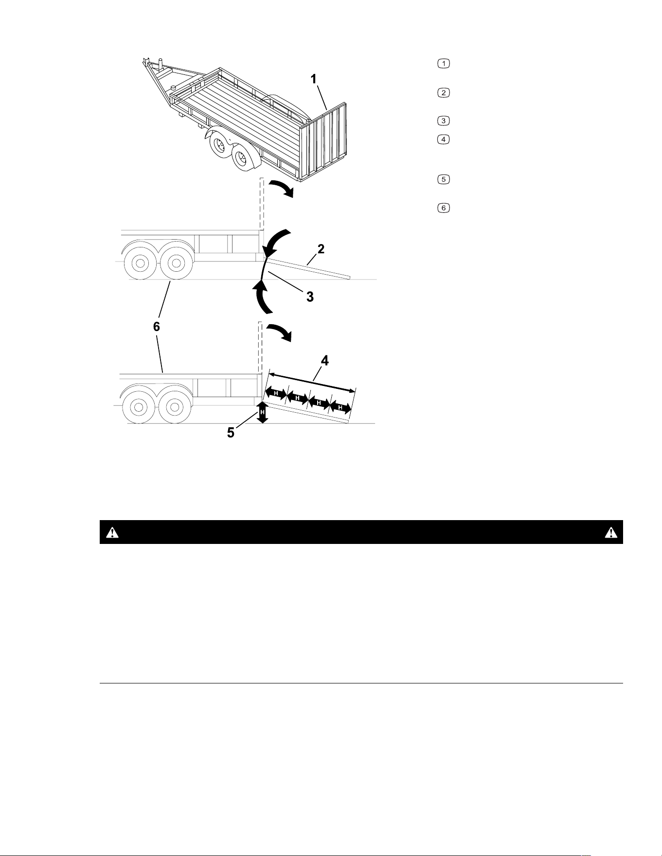
Hauling the Machine (continued)
G027996s
Full-width ramp(s) in stowed
position
Side view of full-width ramp in
loading position
Not greater than 15 degrees
Ramp is at least 4 times as long as
the height of the trailer or truck bed to
the ground
H = height of the trailer or truck bed
to the ground
Trailer
Loading the Machine
WARNING
Loading a machine onto a trailer or truck increases the possibility of tip-over and
could cause serious injury or death.
• Use extreme caution when operating a machine on a ramp.
• Back the machine up the ramp and drive it forward down the ramp.
• Avoid sudden acceleration or deceleration while driving the machine on a ramp as
this could cause a loss of control or a tip-over situation.
1. If using a trailer, connect it to the towing vehicle and connect the safety chains.
2. If applicable, connect the trailer brakes.
3. Lower the ramp, ensuring that the angle between the ramp and the ground does not
exceed 15 degrees.
Operation: After Operation Page 4–21 3473-292 B
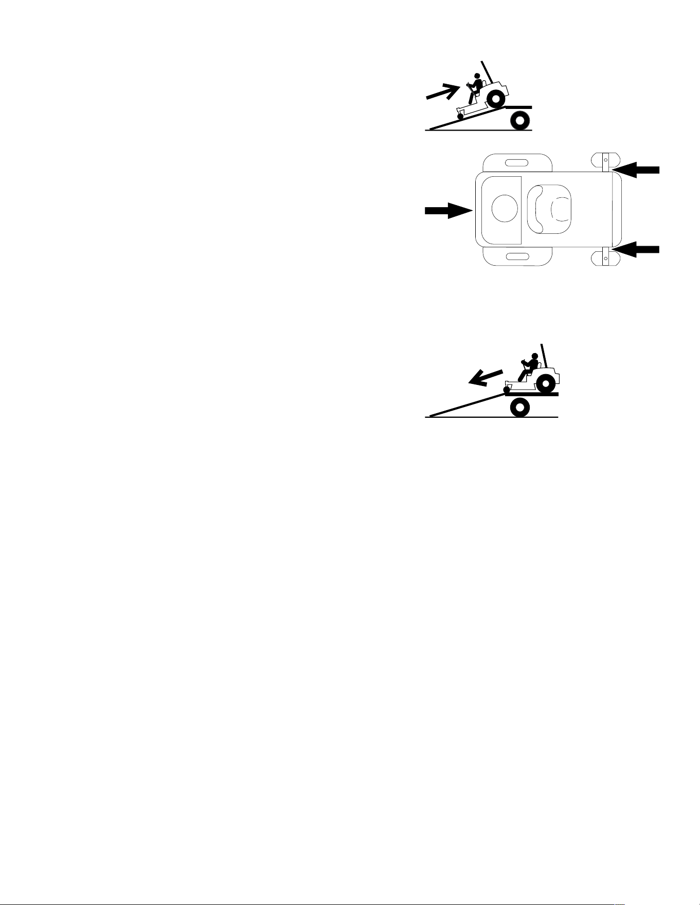
Hauling the Machine (continued)
G414594
4. Back the machine up the ramp.
5. Shut off the engine, remove the key, and
engage the parking brake.
G027708s
6. Tie down the machine using straps, chains,
cable, or ropes. Refer to local regulations for
tie-down requirements.
Unloading the Machine
G414595
1. Lower the ramp, ensuring that the angle
between the ramp and the ground does not
exceed 15 degrees.
2. Drive the machine forward down the ramp.
3473-292B Page 4–22 Operation: After Operation

Chapter 5
Maintenance
Note: Determine the left and right sides of the machine from the normal operating position.
Maintenance Safety
• If you leave the key in the switch, someone could accidently start the engine and
seriously injure you or other bystanders. Remove the key from the switch before you
perform any maintenance.
• Before you leave the operator’s position, do the following:
– Park the machine on a level surface.
– Disengage the drives.
– Engage the parking brake.
– Shut off the engine and remove the key.
– Wait for the machine to cool before performing maintenance.
• Do not allow untrained personnel to service the machine.
• Keep your hands and feet away from moving parts or hot surfaces. If possible, do not
make adjustments with the engine running.
• Keep all guards, shields, switches, and all safety devices in place and in proper working
condition. Frequently check for worn or deteriorating components and replace them with
genuine Spartan parts when necessary.
• Carefully release pressure from components with stored energy.
WARNING
Removing or modifying original equipment, parts, and/or accessories may alter
the warranty, controllability, and safety of the machine. Making unauthorized
modifications to the original equipment or failing to use original Spartan parts
could lead to serious injury or death.
• Check the parking brake operation frequently. Adjust and service it as required.
• Never tamper with safety devices. Check their proper operation regularly.
• Clean grass, leaves, excessive grease and oil, and other debris from the cutting unit,
muffler, drives, grass catcher, and engine compartment to prevent fires.
• Clean up oil or fuel spills and remove fuel-soaked debris.
• Do not rely solely on mechanical or hydraulic jacks to support the machine. Use
adequate jack stands.
Maintenance Page 5–1 3473-292 B

• Keep all parts in good working condition and all hardware tightened, especially the blade-
attachment hardware.
• To ensure optimum performance, use only genuine Spartan replacement parts and
accessories. Replacement parts and accessories made by other manufacturers could be
dangerous.
3473-292B Page 5–2 Maintenance: Maintenance Safety

Recommended Maintenance Schedule
Maintenance
Service Interval
Maintenance Procedure
Before each use or
daily
Check the safety-interlock system.
Inspect the ROPS and mounting hardware. Replace any damaged parts.
Check the air cleaner for dirty, loose, or damaged parts.
Clean the engine screen, engine-oil cooler, and the area around the engine..
Check the engine-oil level.
Check the battery for connection and damage.
Test the parking brake.
Check the hydraulic fluid level.
Check the tire pressure.
Inspect the blades.
Inspect the grass deflector for damage.
Clean under the mower deck.
Check for loose fasteners.
After the first 25
hours
Change the engine oil.
After the first 50
hours
Change the hydraulic fluid for RZ-HD, RZ-XD, RT-HD, SRT XD, and SRT XDe
machines; contact an Authorized Service Dealer.
After the first 200
hours
Change the hydraulic fluid for RT-Pro machines; contact an Authorized Service Dealer.
Monthly
Grease the machine.
Check the belts for wear or cracks.
Check the mower deck belt tension and condition.
Every 100 hours
Change the engine oil and filter (more often in dirty or dusty conditions).
Torque the wheel lug nuts.
Every 200 hours Change the fuel filter.
Every 250 hours
Change the hydraulic fluid for RZ-HD, RZ-XD, RT-HD, SRT XD, and SRT XDe
machines; contact an Authorized Service Dealer.
Every 1,000 hours Change the hydraulic fluid for RT-Pro machines; contact an Authorized Service Dealer.
Yearly or before
storage
Perform all maintenance procedures listed above before storage.
Paint any chipped surfaces.
IMPORTANT
Refer to your engine owner’s manual for additional maintenance procedures.
Maintenance: Recommended Maintenance Schedule Page 5–3 3473-292 B
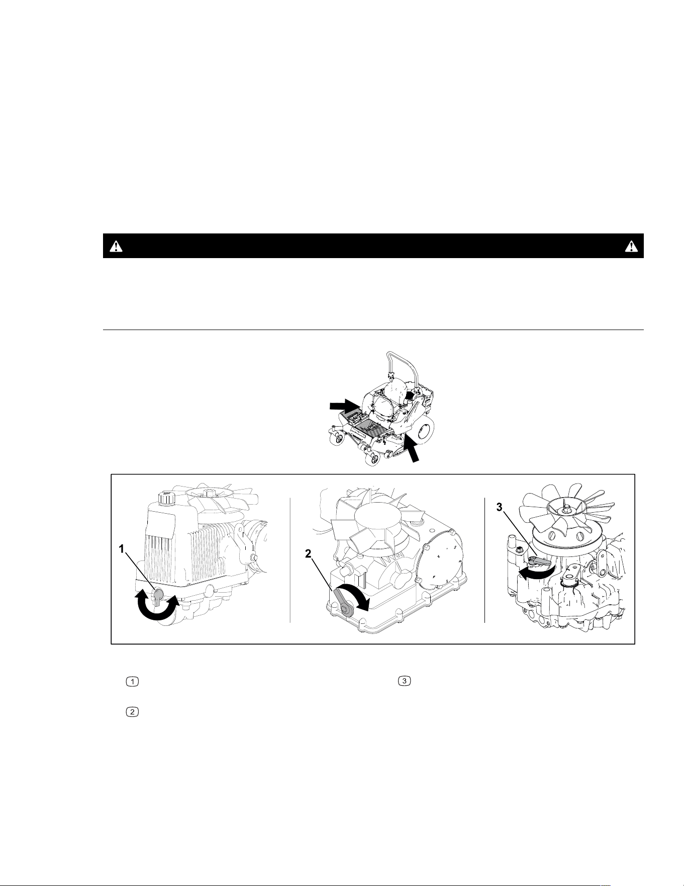
Pre-Maintenance Procedures
Moving a Non-Functioning Machine
1. Park the machine on a level surface, disengage the PTO switch, move the motion-
control levers to the N
EUTRAL-LOCK position, and engage the parking brake.
2. Shut off the engine, remove the key, and wait for all moving parts to stop before leaving
the operating position.
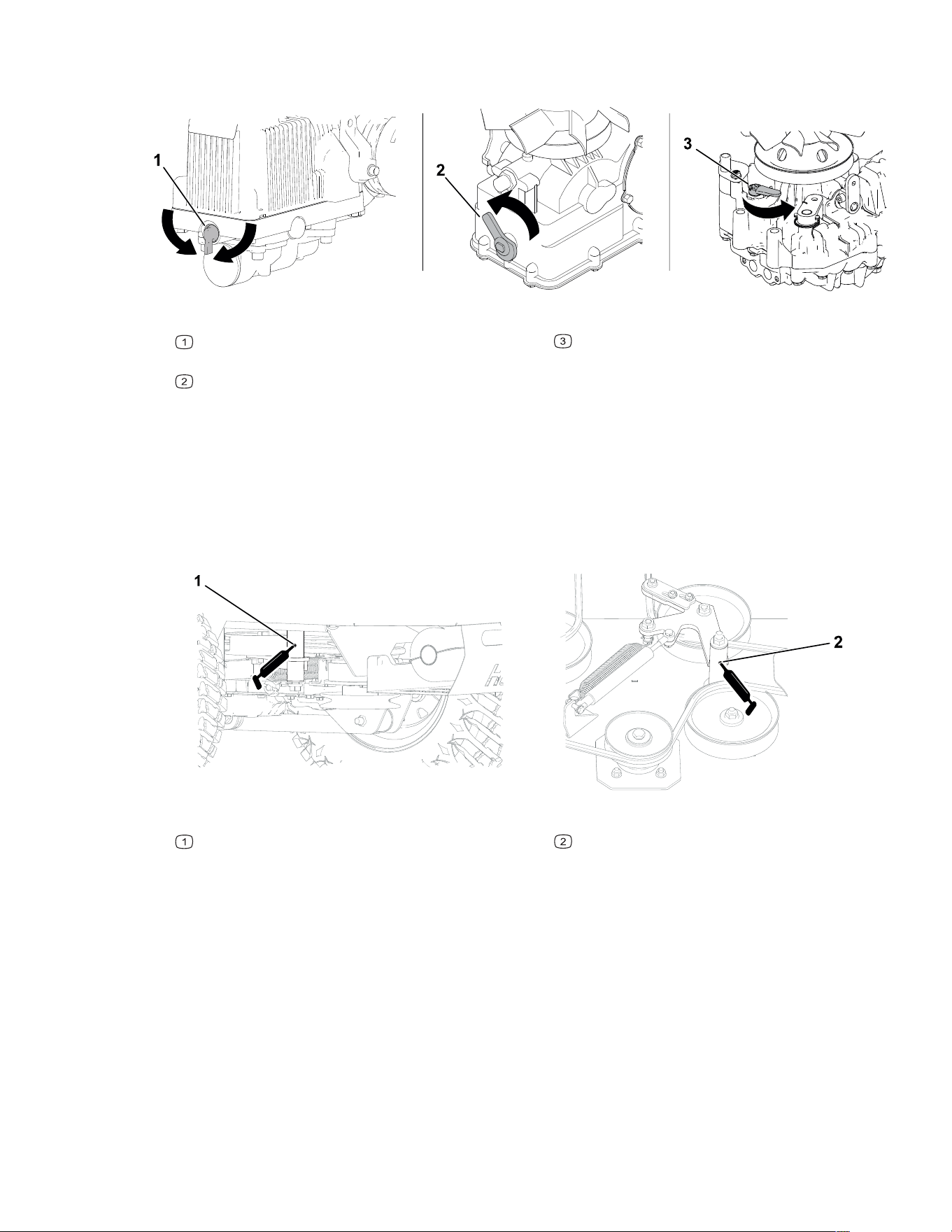
3. On both transmissions, rotate the levers as shown for your machine to open the bypass
valves.
WARNING
The machine could unintentionally move while the transmissions are bypassed and
injure you or bystanders.
Close the bypass valves after moving the machine.
G515861
RZ-HD, RZ-XD, RT-HD, and SRT XDe machines
—rotate the lever left or right.
SRT XD machines—rotate the lever left.
RT-Pro machines—rotate the lever right.
4. Disengage the parking brake.
5. Move the machine as required.
6. Immediately after moving the machine, engage the parking brake.
7. Move the bypass levers as shown to close the bypass valves.
3473-292B Page 5–4 Maintenance: Pre-Maintenance Procedures
Moving a Non-Functioning Machine (continued)
G515860
RZ-HD, RZ-XD, RT-HD, and SRT XDe machines
—rotate the lever down.
SRT XD—rotate the lever right.
RT-Pro machines—rotate the lever left.
Lubrication
Greasing the Machine
Grease type: No. 2 lithium or molybdenum grease
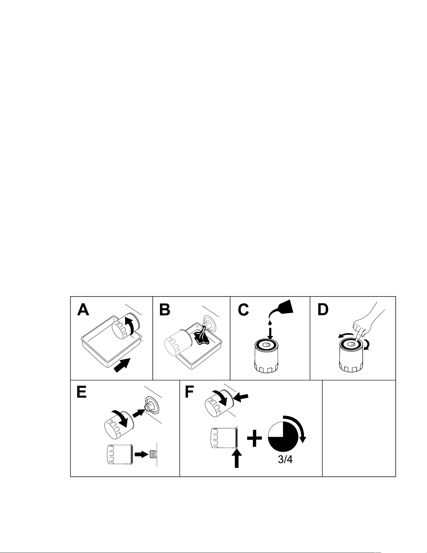
G515668
Deck idler fitting
Pump idler fitting
1. Park the machine on a level surface, disengage the PTO switch, move the motion-
control levers to the N
EUTRAL-LOCK position, and engage the parking brake.
2. Shut off the engine, remove the key, and wait for all moving parts to stop before leaving
the operating position.
3. Allow the machine to cool.
4. Clean the grease fittings with a rag.
Note: Scrape any paint off the front of the fitting(s).
5. Connect a grease gun to the fitting.
6. Pump grease into the fittings until grease begins to ooze out of the bearings.
7. Wipe up any excess grease.
Maintenance: Lubrication Page 5–5 3473-292 B

Engine Maintenance
IMPORTANT
For more specific information about your machine’s engine, refer to the engine
owner’s manual or visit https://spartanmowers.com/company/owner-info/.
Engine Safety
• Keep your hands, feet, face, other body parts, and clothing away from the muffler and
other hot surfaces. Wait for the engine to cool before performing maintenance.
• Do not change the engine governor speed or overspeed the engine.
Servicing the Air Cleaner
1. Park the machine on a level surface, disengage the PTO switch, move the motion-
control levers to the N
EUTRAL-LOCK position, and engage the parking brake.
2. Shut off the engine, remove the key, and wait for all moving parts to stop before leaving
the operating position.
3. Release the retaining clamps on the air cleaner and pull the air-cleaner cover off the air-
cleaner body.
4. Clean or replace the filter elements per the engine manufacturer’s instructions.
5. Install the air-cleaner cover and secure the latches.
3473-292B Page 5–6 Maintenance: Engine Maintenance
Engine Oil Service
Checking the Engine-Oil Level
1. Park the machine on a level surface, disengage the PTO switch, move the motion-
control levers to the N
EUTRAL-LOCK position, and engage the parking brake.
2. Shut off the engine, remove the key, and wait for all moving parts to stop before leaving
the operating position.
3. Wait for the engine to cool to allow the oil to drain into the sump.
4. Check the engine-oil level per the engine manufacturer’s instructions.
Changing the Engine Oil and Filter
1. Park the machine so that the drain side is slightly lower than the opposite side to ensure
that the oil drains completely.
2. Disengage the PTO switch, move the motion-control levers to the N
EUTRAL-LOCK position,
and engage the parking brake.
3. Shut off the engine, remove the key, and wait for all moving parts to stop before leaving
the operating position.
4. Clean the area around the oil-fill cap. Remove the cap.
5. Place a drain pan under the drain plug.
6. Remove the plug and allow the oil to drain.
7. Install the plug.
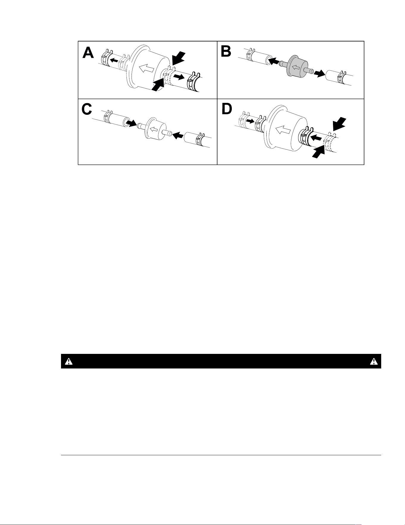
8. Change the engine-oil filter as shown.
G398545s
9. Slowly pour approximately 80% of the oil specified by the engine manufacturer into the
filler tube and slowly add the additional oil to bring it to the appropriate level.
Maintenance: Engine Maintenance Page 5–7 3473-292 B

Engine Oil Service (continued)
10. Start the engine and check for leaks.
11. Stop the engine, remove the key, and check the oil level.
12. Dispose of the used oil at a recycling center.
Servicing the Spark Plugs
1. Park the machine on a level surface, disengage the PTO switch, move the motion-
control levers to the N
EUTRAL-LOCK position, and engage the parking brake.
2. Shut off the engine, remove the key, and wait for all moving parts to stop before leaving
the operating position.
3. Service the spark plugs per the engine manufacturer’s instructions.
Fuel Maintenance
DANGER
In certain conditions, fuel is extremely flammable and highly explosive. A fire or
explosion from fuel can burn you and others and can damage property.
Refer to Fuel Safety, page 4–2 for a complete list of fuel related precautions.
Replacing the Fuel Filter
1. Park the machine on a level surface, disengage the PTO switch, move the motion-
control levers to the N
EUTRAL-LOCK position, and engage the parking brake.
2. Shut off the engine, remove the key, and wait for all moving parts to stop before leaving
the operating position.
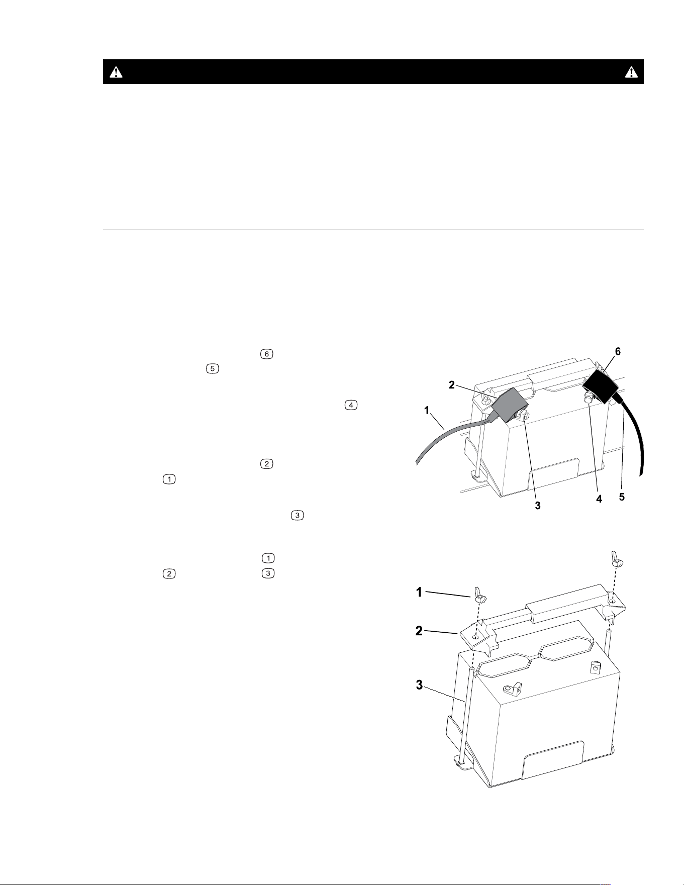
3. Clamp the fuel lines on both sides of the fuel filter.
4. Replace the filter.
Note: Ensure that the flow-direction arrow on the replacement filter points toward the
engine.
IMPORTANT
Never install a dirty filter after removing it from the fuel line.
3473-292B Page 5–8 Maintenance: Engine Maintenance
Replacing the Fuel Filter (continued)
G420323
5. Remove the clamps blocking the fuel flow.
Electrical System Maintenance
Electrical System Safety
• Disconnect the cable from the negative terminal of the battery before repairing the
machine.
• Charge the battery in an open, well-ventilated area, away from sparks and flames.
Unplug the charger before connecting or disconnecting the battery. Wear protective
clothing and use insulated tools.
Battery Service
Removing the Battery
WARNING
Battery terminals or metal tools could short against metal machine components,
causing sparks. Sparks can cause the battery gasses to explode, resulting in
personal injury.
• When removing or installing the battery, do not allow the battery terminals to
touch any metal parts of the machine.
• Do not allow metal tools to short between the battery terminals and metal parts of
the machine.
Maintenance: Electrical System Maintenance Page 5–9 3473-292 B
Battery Service (continued)
WARNING
Incorrectly removing the cables from the battery could damage the machine and
cables, causing sparks. Sparks can cause the battery gasses to explode, resulting in
personal injury.
• Always disconnect the negative (black) battery cable before disconnecting the
positive (red) cable.
• Always connect the positive (red) battery cable before connecting the negative
(black) cable.
1. Park the machine on a level surface, disengage the PTO switch, move the motion-
control levers to the N
EUTRAL-LOCK position, and engage the parking brake.
2. Shut off the engine, remove the key, and wait for all moving parts to stop before leaving
the operating position.
3. Allow the machine to cool.
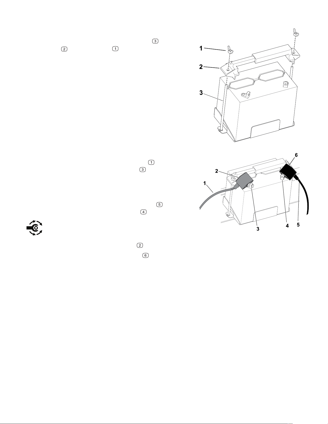
G421097
4. Slide the rubber cover off the negative
(black) cable
.
5. Disconnect the negative (black) ground cable
from the negative (-) battery terminal
.
Note: Retain all fasteners. The fasteners for
some batteries may be different than shown.
6. Slide the rubber cover
off the positive (red)
cable
.
7. Disconnect the positive (red) cable from the
positive (+) battery terminal
.
Note: Retain all fasteners.
G421098
8. Remove the wing nuts and battery hold-
down
from the rods , and remove the
battery.
3473-292B Page 5–10 Maintenance: Electrical System Maintenance
Battery Service (continued)
Charging the Battery
WARNING
Charging the battery produces gasses that can explode.
Never smoke near the battery and keep sparks and flames away from battery.
IMPORTANT
Always keep the battery fully charged. This is especially important to prevent battery
damage when the temperature is below 0°C (32°F).
1. Remove the battery from the machine.
2. Charge the battery per the battery charger manufacturer’s instructions.
IMPORTANT
Do not overcharge the battery; otherwise, you could damage it.
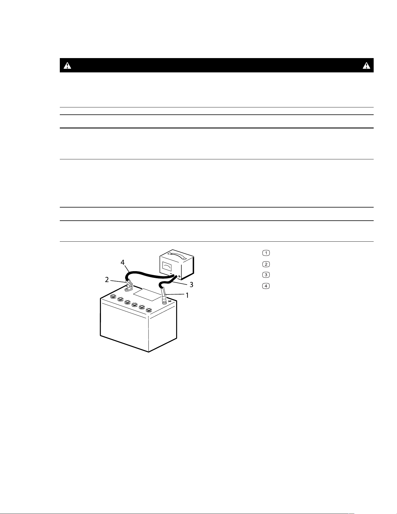
G003792S
Positive battery post
Negative battery post
Red (+) charger lead
Black (-) charger lead
3. When the battery is fully charged, unplug the charger from the electrical outlet (if
applicable), then disconnect the charger leads from the battery posts.
Maintenance: Electrical System Maintenance Page 5–11 3473-292 B

Battery Service (continued)
Cleaning the Battery
Note: Keep the terminals and the entire battery case clean, because a dirty battery
discharges slowly.
1. Park the machine on a level surface, disengage the PTO switch, move the motion-
control levers to the N
EUTRAL-LOCK position, and engage the parking brake.
2. Shut off the engine, remove the key, and wait for all moving parts to stop before leaving
the operating position.
3. Remove the battery from the machine.
4. Wash the entire case with a solution of baking soda and water.
5. Rinse the battery with clear water.
6. Coat the battery posts and cable connectors with Grafo 112X (skin-over) grease or
petroleum jelly to prevent corrosion.
7. Install the battery.
Installing the Battery
WARNING
Battery terminals or metal tools could short against metal machine components,
causing sparks. Sparks can cause the battery gasses to explode, resulting in
personal injury.
• When removing or installing the battery, do not allow the battery terminals to
touch any metal parts of the machine.
• Do not allow metal tools to short between the battery terminals and metal parts of
the machine.
WARNING
Incorrectly removing the cables from the battery could damage the machine and
cables, causing sparks. Sparks can cause the battery gasses to explode, resulting in
personal injury.
• Always disconnect the negative (black) battery cable before disconnecting the
positive (red) cable.
• Always connect the positive (red) battery cable before connecting the negative
(black) cable.
3473-292B Page 5–12 Maintenance: Electrical System Maintenance
Battery Service (continued)
G421098
1. Position the battery on the tray.
2. Secure the battery with the rods
, hold-down
, and wing nuts .
G421097
3. Using the fasteners previously removed, install
the positive (red) battery cable
to the
positive (+) battery terminal
.
Note: The fasteners for some batteries may
be different than shown.
4. Using the fasteners previously removed, install
the negative (black) battery cable
to the
negative (-) battery terminal
.
5. Torque the bolts to 5.7 to 6.8 N∙m (50 to 60 in-
lb).
6. Slide the red terminal boot
onto the positive (red) battery post.
7. Slide the black terminal boot
onto the negative (black) battery post.
Servicing a Replacement Battery
The original battery is maintenance-free and does not require service. For servicing a
replacement battery, refer to the battery manufacturer’s instructions.
Maintenance: Electrical System Maintenance Page 5–13 3473-292 B
Replacing the Fuses
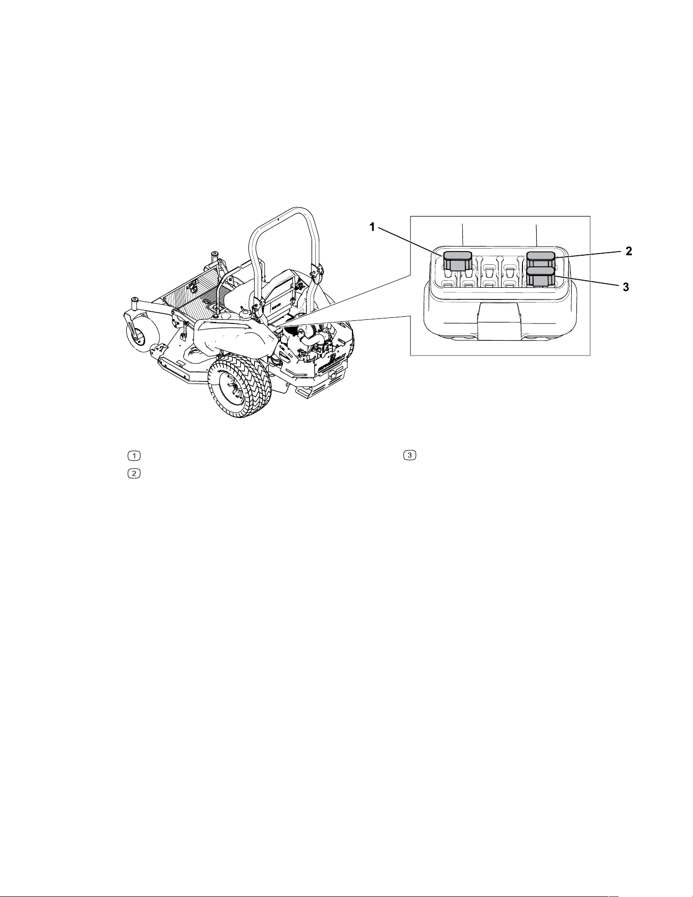
The electrical system is protected by fuses. It requires no maintenance; however, if a fuse
blows, check the component/circuit for a fault.
1. Park the machine on a level surface, disengage the PTO switch, move the motion-
control levers to the N
EUTRAL-LOCK position, and engage the parking brake.
2. Shut off the engine, remove the key, and wait for all moving parts to stop before leaving
the operating position.
3. Pull out the fuse and replace it.
G515408
Fuse—30 A
Fuse—20 A
Fuse—10 A
3473-292B Page 5–14 Maintenance: Electrical System Maintenance
Drive System Maintenance
Checking the Seat Belt
Inspect the seat belt for wear, cuts, and proper operation of the retractor and buckle.
Replace the seat belt if it is damaged.
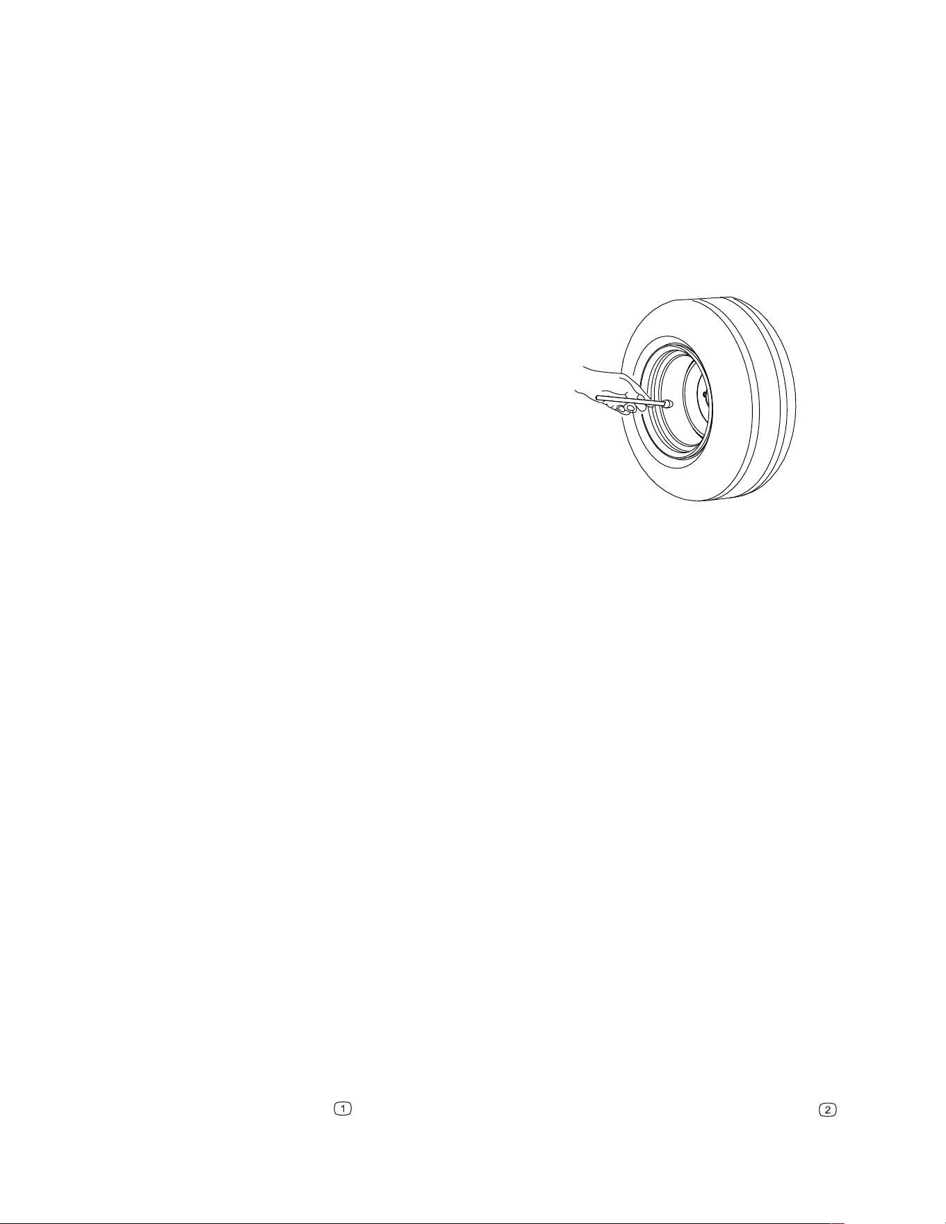
Checking the Tire Pressure
G001055s
Maintain the air pressure in the front and rear tires
as specified. Check the tires when they are cold to
get the most accurate pressure reading.
Uneven tire pressure can cause an uneven
cut.
• Front wheels: 55 kPa (8 psi)
• Rear wheels: 83 kPa (12 psi)
Note: Tweel
®
tires do not require inflation.
Belt Maintenance
Inspecting the Belts
1. Park the machine on a level surface, disengage the PTO switch, move the motion-
control levers to the N
EUTRAL-LOCK position, and engage the parking brake.
2. Shut off the engine, remove the key, and wait for all moving parts to stop before leaving
the operating position.
3. Set the height of cut at the lowest cutting position.
4. Inspect the belt for wear. Replace the belt if it is worn.
The signs of a worn belt include squealing while the belt is rotating; the blades slipping
while cutting grass; and frayed edges, burn marks, and cracks on the belt.
Replacing the Mower-Deck Belt
1. Park the machine on a level surface, disengage the PTO switch, move the motion-
control levers to the N
EUTRAL-LOCK position, and engage the parking brake.
2. Shut off the engine, remove the key, and wait for all moving parts to stop before leaving
the operating position.
3. Set the height of cut to the lowest cutting position.
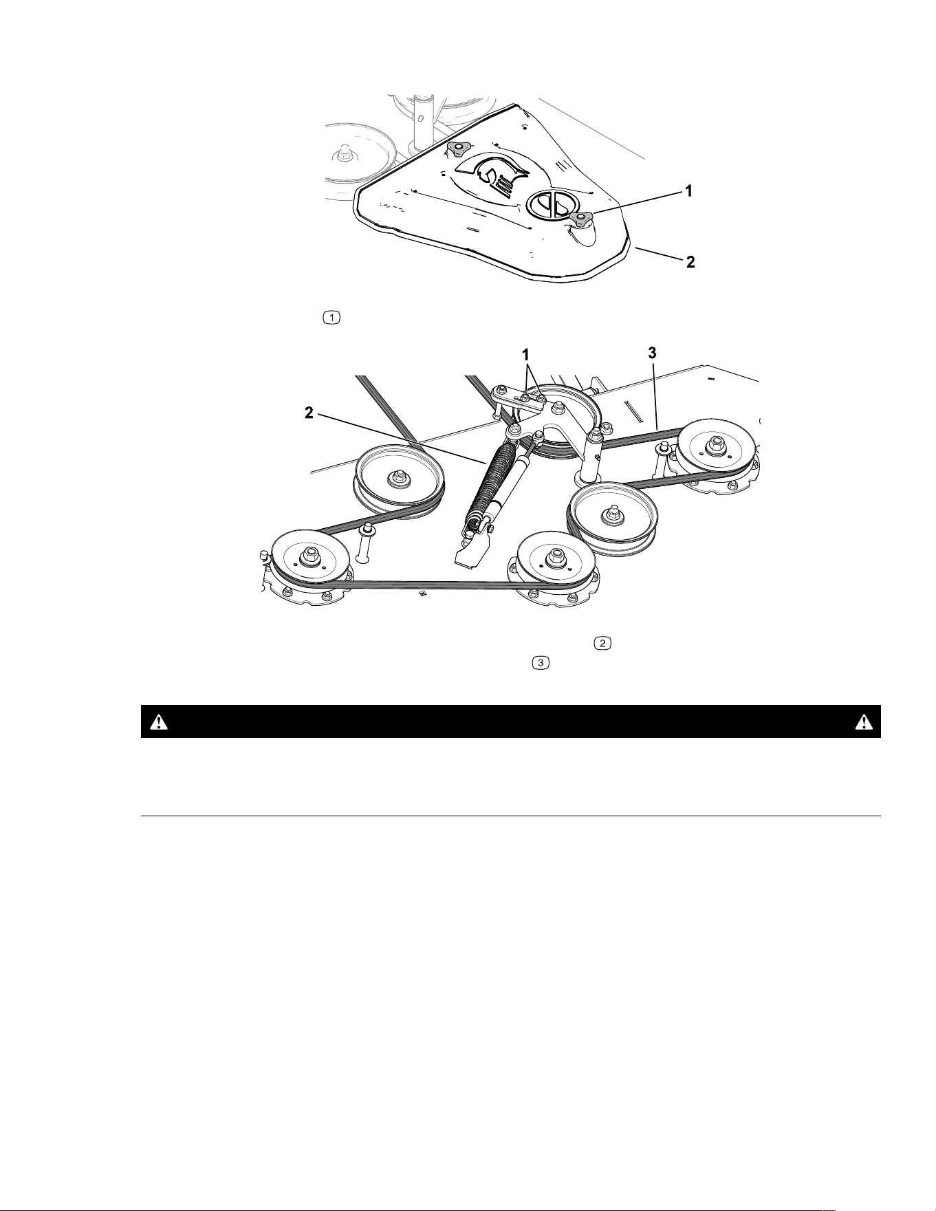
4. Remove the knobs
securing the pulley covers and remove the pulley covers .
Maintenance: Drive System Maintenance Page 5–15 3473-292 B
Replacing the Mower-Deck Belt (continued)
G464441
5. Loosen the 2 nuts on the idler pulley and slide the bracket away from the pulley.
G464442
6. Using a spring-removal tool, remove the idler spring from the deck hook to remove
tension from the idler pulley, and roll the belt
off the pulleys.
WARNING
The spring is under tension when installed and can cause personal injury.
Be careful when removing the belt.
7. Route the new belt around the engine pulley and mower pulleys.
8. Use the spring-removal tool to install the idler spring over the deck hook and place
tension on the idler pulley and the mower belt.
9. Slide the idler bracket so that the shoulder bolt is within 4.7 mm (3/16 inch) of the belt.
Tighten the nuts.
10. Install the pulley covers.
Replacing the Pump-Drive Belt
Contact an Authorized Service Dealer to replace the pump-drive belt.
3473-292B Page 5–16 Maintenance: Belt Maintenance

Hydraulic System Maintenance
Hydraulic System Safety
• Seek immediate medical attention if hydraulic fluid is injected into the skin. Injected fluid
must be surgically removed within a few hours by a doctor familiar with this form of injury;
otherwise, gangrene may result.
• Ensure that all hydraulic-fluid hoses and lines are in good condition and all hydraulic
connections and fittings are tight before applying pressure to the hydraulic system.
• Keep your body and hands away from pinhole leaks or nozzles that eject high-pressure
hydraulic fluid.
• Use cardboard or paper, not your hands, to find hydraulic leaks.
• Safely relieve all pressure in the hydraulic system before performing any work on the
hydraulic system.
Hydraulic-Fluid Specifications
Hydraulic Fluid Type:
Machine Fluid
RZ-HD, RZ-XD, RT-HD, SRT XD, and SRT XDe Spartan Premium Hydrostat Oil or Parker HT-
1000™ Hydraulic Fluid
RT-Pro Tuff Tech™ Hydrostatic Drive Fluid
IMPORTANT
Use the fluid specified. Other fluids could damage the system.
Checking the Hydraulic Fluid for RZ-HD, RZ-XD, RT-HD,
and SRT XDe Machines
1. Park the machine on a level surface, disengage the PTO switch, move the motion-
control levers to the N
EUTRAL-LOCK position, and engage the parking brake.
2. Shut off the engine, remove the key, and wait for all moving parts to stop before leaving
the operating position.
3. Allow the machine to cool.
Note: Only check the hydraulic fluid when the system is cold.
4. Tilt the seat forward.
Maintenance: Hydraulic System Maintenance Page 5–17 3473-292 B
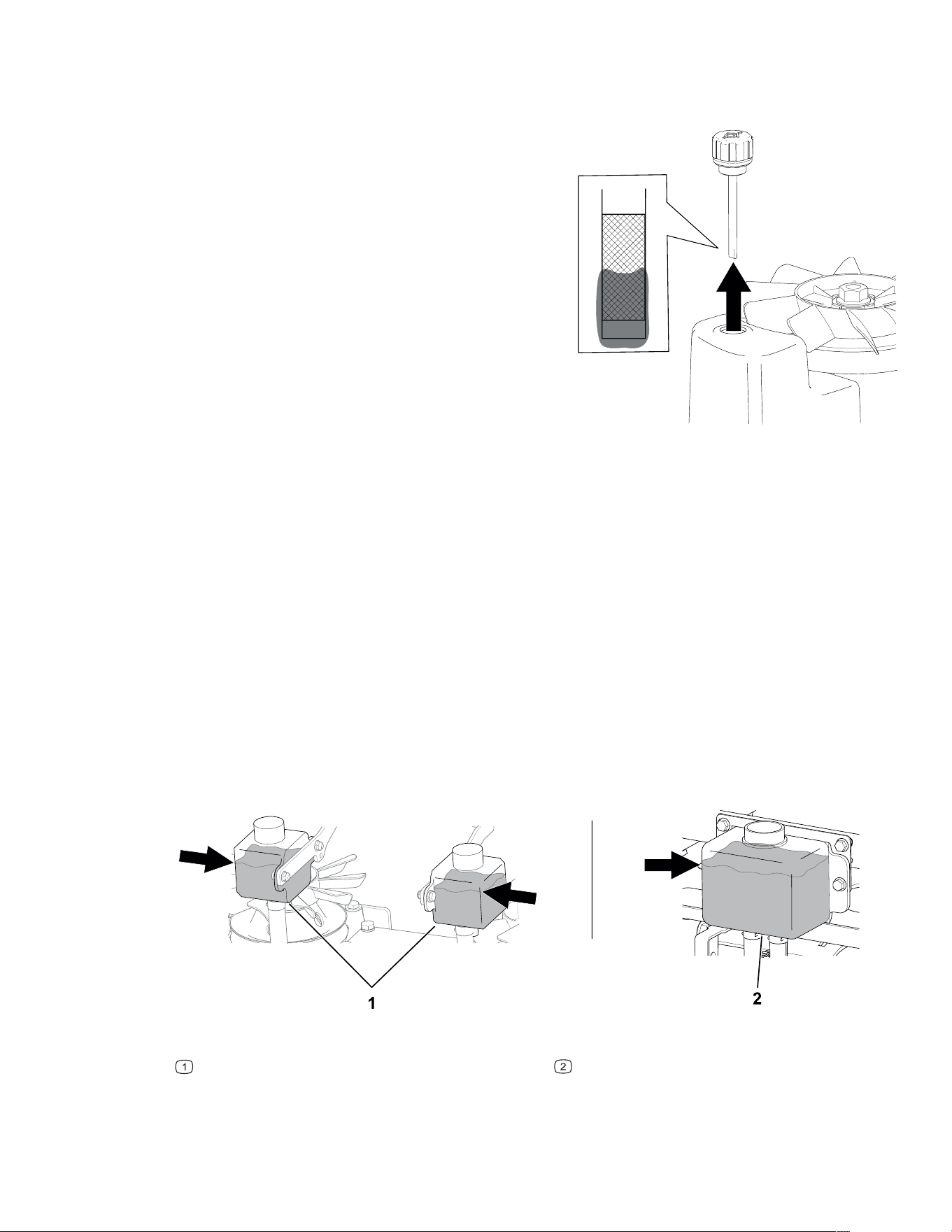
Checking the Hydraulic Fluid for RZ-HD, RZ-XD, RT-HD,
and SRT XDe Machines (continued)
G429478
5. Clean the area around the dipstick cap for
each transmission and remove the cap.
6. Wipe the dipstick clean, insert it into the
transmission, and lightly tighten the cap.
7. Remove the cap again and check the fluid
level on the dipstick.
The fluid should be within the hashed area of
the dipstick.
8. If the level is low, add enough fluid to raise it to
the proper level.
9. Install the dipstick and tighten the cap.
Checking the Hydraulic Fluid for RT-Pro and SRT XD
Machines
1. Park the machine on a level surface, disengage the PTO switch, move the motion-
control levers to the N
EUTRAL-LOCK position, and engage the parking brake.
2. Shut off the engine, remove the key, and wait for all moving parts to stop before leaving
the operating position.
3. Allow the machine to cool.
Note: Only check the hydraulic fluid when the system is cold.
4. Tilt the seat forward.
5. Clean the area around the cap and the filler neck of the hydraulic tank(s).
G517197
RT-Pro hydraulic tanks
SRT XD hydraulic tank
6. Remove the cap from the filler neck.
3473-292B Page 5–18 Maintenance: Hydraulic System Maintenance

Checking the Hydraulic Fluid for RT-Pro and SRT XD
Machines (continued)
7. Verify that the fluid is about 2.5 cm (1 inch) away from the bottom of the filler neck.
8. If the level is low, add enough fluid to raise it to the proper level.
9. Install the cap on the filler neck.
Changing the Hydraulic Fluid
To change the hydraulic fluid, contact an Authorized Service Dealer.
Mower-Deck Maintenance
Blade Safety
• Inspect the blades periodically for wear or damage.
• Use care when checking the blades. Wrap the blade(s) or wear gloves and use caution
when servicing them. Only replace damaged blades; never straighten or weld them.
• On multi-bladed machines, take care as rotating one blade can cause other blades to
rotate.
• Replace worn or damaged blades and bolts in sets to preserve balance.
Blade Service
To ensure a superior quality of cut, keep the blades sharp. For convenient sharpening and
replacement, keep extra blades on hand.
Replace the blades if they hit a solid object, or if the blade is out of balance or bent.
Maintenance: Hydraulic System Maintenance Page 5–19 3473-292 B
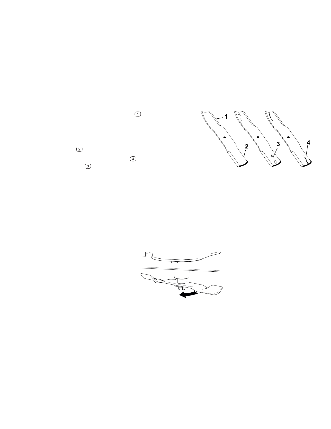
Blade Service (continued)
Before Inspecting or Servicing the Blades
1. Park the machine on a level surface, disengage the PTO switch, move the motion-
control levers to the N
EUTRAL-LOCK position, and engage the parking brake.
2. Shut off the engine, remove the key, and wait for all moving parts to stop before leaving
the operating position.
3. Disconnect the spark-plug wires from the spark plugs.
Inspecting the Blades
G006530s
1. Inspect the cutting edges .
2. If the edges are not sharp or have nicks,
remove and sharpen the blade.
3. Inspect the blades, especially in the curved
area
.
4. If you notice any cracks
, wear, or a slot
forming
in this area, immediately install a
new blade.
Checking for Bent Blades
The machine must be on a level surface for this procedure.
1. Raise the mower deck to the highest height-of-cut position.
2. While wearing thickly padded gloves, or other adequate hand protection, slowly rotate
the blade into a position that allows you to measure the distance between the cutting
edge and the level surface.
G464561
3. Measure from the tip of the blade to the level surface.
3473-292B Page 5–20 Maintenance: Mower-Deck Maintenance
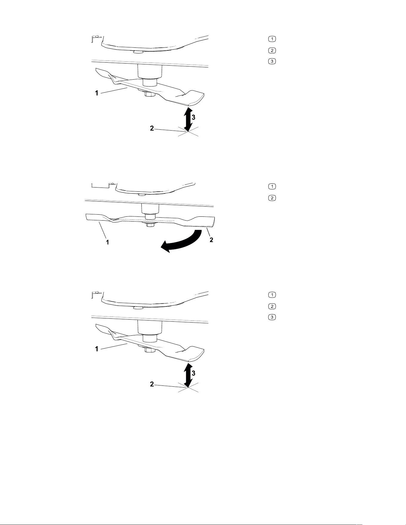
Blade Service (continued)
G464559
Blade (in position for measuring)
Level surface
Measured distance between blade
and the surface (A)
4. Rotate the same blade 180 degrees so that the opposite blade edge is now in the same
position.
G464560
Blade edge previous measured
Opposite blade edge
5. Measure from the tip of the blade to the level surface.
G464559
Blade (in position for measuring)
Level surface
Measured distance between blade
and the surface (B)
6. If the difference between A and B is greater than 3 mm (1/8 inch), replace the blade.
Note: If you replace the blade and the difference continues to exceed 3 mm (1/8 inch),
the blade spindle could be bent. Contact an Authorized Service Dealer for service.
7. Repeat this procedure each blade.
Maintenance: Mower-Deck Maintenance Page 5–21 3473-292 B
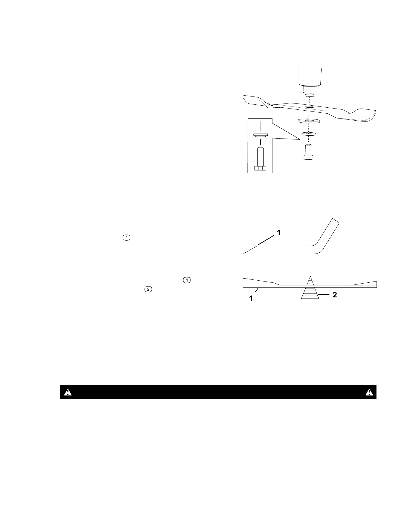
Blade Service (continued)
Removing the Blades
Replace the blades if they hit a solid object, or if the blade is out of balance or bent.
G464584
1. Hold the blade end using a rag or thickly
padded glove.
2. Remove the blade as shown.
Sharpening the Blades
G000552s
1. Use a file to sharpen the cutting edge at both
ends of the blade. Ensure to maintain the
original angle
.
Note: Remove the same amount of material
from both cutting edges so that the blade
retains its balance.
G000553s
2. Check the balance of the blade by putting it
on a blade balancer
.
Note: If the blade stays in a horizontal
position, the blade is balanced and can be
used.
If the blade is not balanced, file some metal off the end of the sail area only.
3. Repeat this procedure until the blade is balanced.
Installing the Blades
WARNING
Operating a machine after incorrectly installing the blade assembly and/or not using
genuine Spartan blade and blade hardware could allow a blade or blade component
to be thrown out from under the deck, resulting in serious injury or death.
Always install genuine Spartan blades and blade hardware according to the
instructions.
3473-292B Page 5–22 Maintenance: Mower-Deck Maintenance
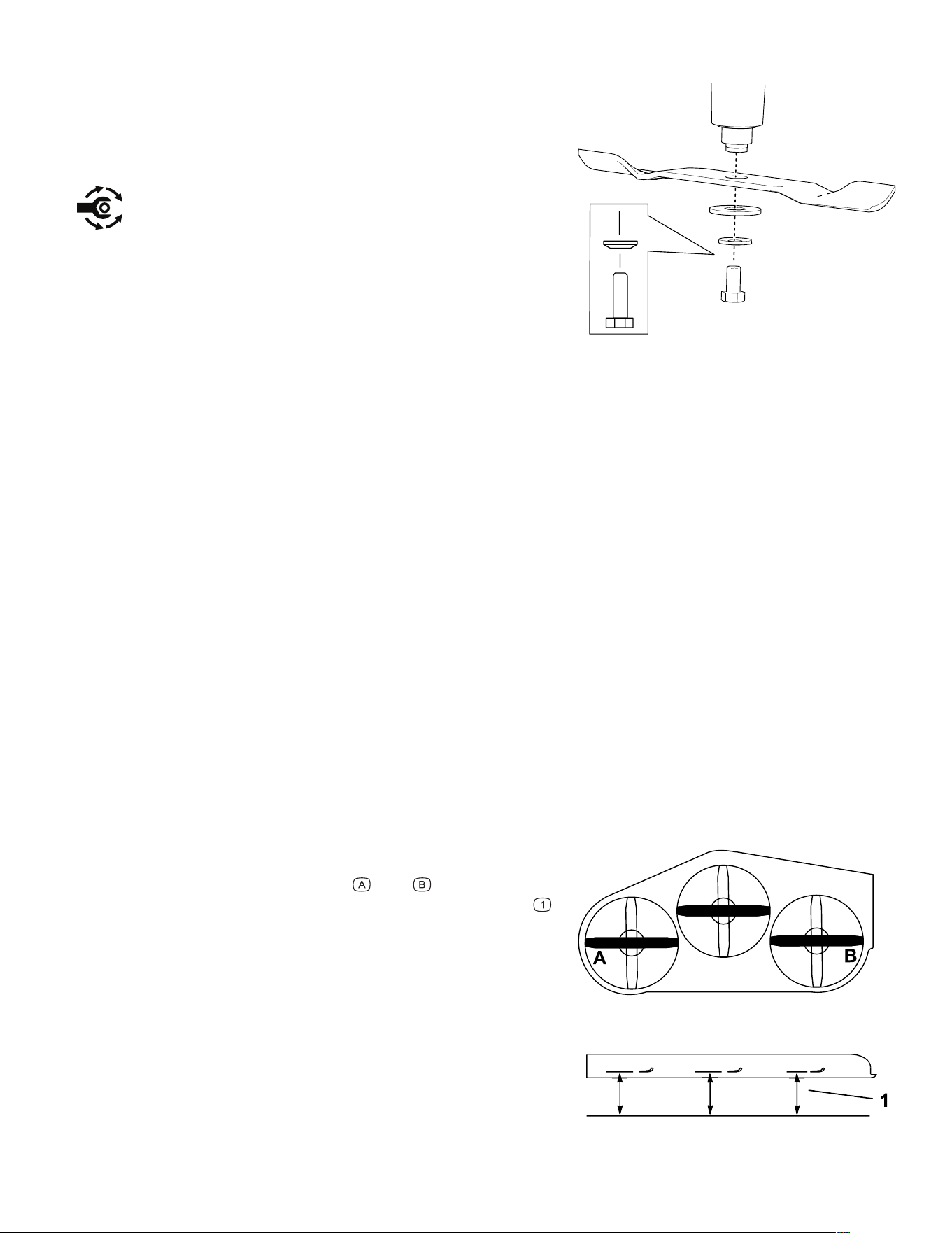
Blade Service (continued)
G464584
1. Install the blade as shown.
Note: The curved part of the blade must be
pointing upward toward the inside of the
mower to ensure proper cutting.
2. Torque the blade bolt to 176 to 190 N∙m (130
to 140 ft-lb).
Leveling the Mower Deck
Ensure that the mower deck is level any time you install the mower deck or when you see an
uneven cut on your lawn.
Preparing to Level the Mower Deck
1. Park the machine on a level surface, disengage the PTO switch, move the motion-
control levers to the N
EUTRAL-LOCK position, and engage the parking brake.
2. Shut off the engine, remove the key, and wait for all moving parts to stop before leaving
the operating position.
3. Disconnect the negative (-) battery cable from the battery.
4. Ensure that the tires are inflated to the correct specifications and the caster wheels are
facing straight forward.
5. Check the mower deck for bent blades; remove and replace any bent blades.
6. Raise the mower deck to the 11.4 cm (4-1/2 inch) height-of-cut setting.
Checking the Mower Deck Level
G414698
1. Position the blades side-to-side.
2. Measure at locations
and from a level
surface to the cutting edge of the blade tips
.
The difference between the measurements
should be no more than 6 mm (1/4 inch). If the
measurement is larger, adjust the side-to-side
level.
Maintenance: Mower-Deck Maintenance Page 5–23 3473-292 B
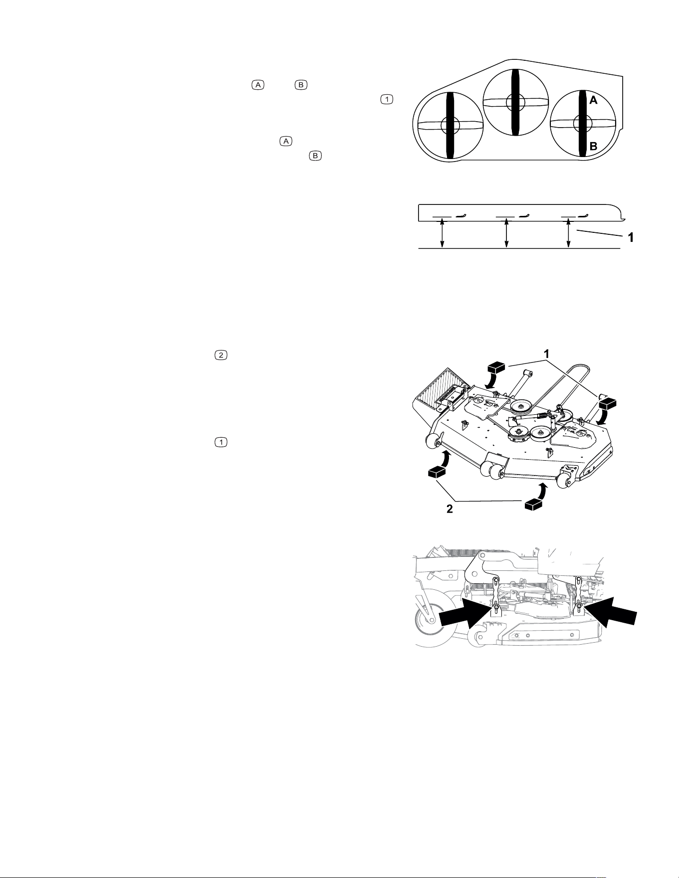
Leveling the Mower Deck (continued)
G414700
3. Position 1 blade front-to-rear.
4. Measure at locations
and from a level
surface to the cutting edge of the blade tips
.
The mower blade should be 11.4 cm (4-1/2
inches) in front at location
and 12.1 cm (4-3/
4 inches) in the rear at location
. If the
measurements are not correct, adjust the
front-to-rear level.
Leveling the Mower Deck
RZ Machines Only
G464605
1. Place 2 blocks , each having a thickness of
3.2 cm (1-1/4 inches), under the front of the
mower deck, in line with the tires.
Note: Place the blocks under a flat edge; do
not place them under the anti-scalp rollers.
2. Place 2 blocks
, each having a thickness of
3.8 cm (1-1/2 inches), under the rear of the
mower deck, in line with the tires.
Note: Place the blocks under a flat edge.
3. Lower the mower deck to the 3.2 cm (1-1/4
inch) height of cut.
G464606
4. Loosen the bolts on all 4 deck-mounting
brackets.
Note: The bolt heads face outward on some
mower decks.
5. Using a strap, pull the deck-lift pedal fully
rearward.
Note: This ensures that the pin from the
height-of-cut selector seats properly in the
deck-height cam assembly.
6. Ensure that the deck rests on the blocks.
3473-292B Page 5–24 Maintenance: Mower-Deck Maintenance
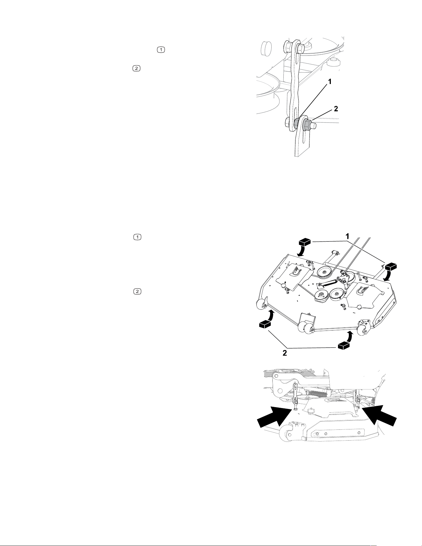
Leveling the Mower Deck (continued)
G464607
7. On each bracket, ensure the bolt is straight.
While holding the nut
between the mounting
bracket and hanger bracket with a wrench,
tighten the nut
at the end of the bolt.
8. Ensure that the brackets are not loose.
Leveling the Mower Deck
RT and SRT Machines Only
1. Raise the mower deck to the highest setting.
G429852
2. Place 2 blocks , each having a thickness of
11.4 cm (4-1/2 inches), under the front of the
mower deck, in line with the tires.
Note: Place the blocks under a flat edge; do
not place them under the anti-scalp rollers.
3. Place 2 blocks
, each having a thickness of
12.1 cm (4-3/4 inches), under the rear of the
mower deck, in line with the tires.
Note: Place the blocks under a flat edge.
4. Lower the mower deck to the 11.4 cm (4-1/2
inch) height of cut.
G429853
5. Loosen the bolts on top of the deck at all 4
deck-adjustment linkages.
6. Using a strap, pull the deck-lift pedal fully
rearward.
Note: This ensures that the pin from the
height-of-cut selector seats properly in the
deck-height cam assembly.
Maintenance: Mower-Deck Maintenance Page 5–25 3473-292 B
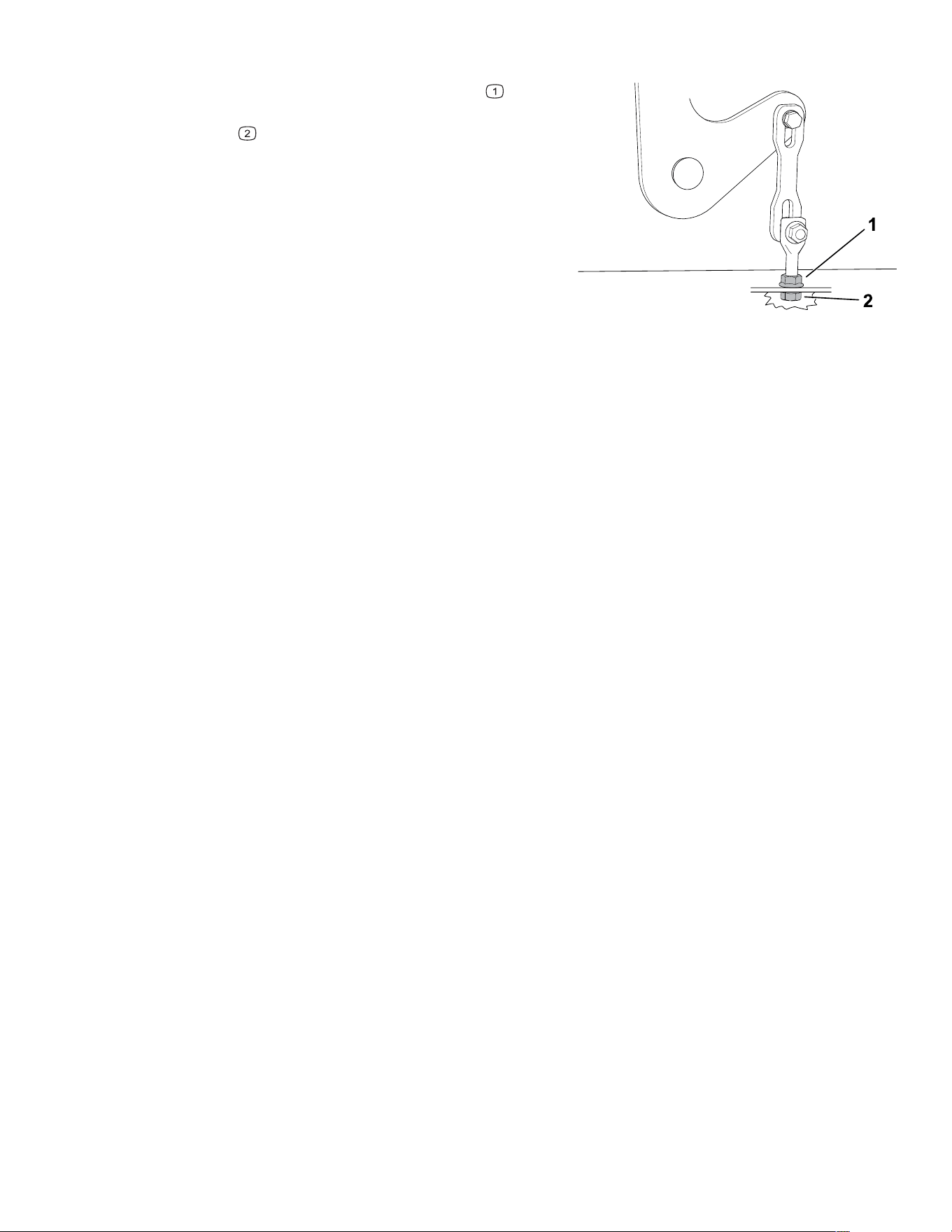
Leveling the Mower Deck (continued)
G429854
7. At each linkage, while holding the nut on
top of the deck with a wrench, tighten or loosen
the nut
underneath the deck so that the
deck rests on the blocks and the linkages are
not loose.
8. Tighten the bolts on top of the deck at all 4
linkages.
Cleaning
Disposing of Waste
Engine oil, batteries, hydraulic fluid, and engine coolant are pollutants to the environment.
Dispose of these according to your state and local regulations.
3473-292B Page 5–26 Maintenance: Cleaning

Chapter 6
Storage
Storage Safety
• Park the machine on a level surface, disengage the drives, engage the parking brake,
shut off the engine, remove the key, and wait for all moving parts to stop before leaving
the operator’s position.
• Wait for the machine to cool before servicing, adjusting, fueling, cleaning, or storing it.
• Clean grass and debris from the cutting unit, muffler, drives, grass catcher, and engine
compartment to prevent fires.
• Clean up oil and fuel spills and remove fuel-soaked debris.
• Do not store the machine or fuel container where there is an open flame, spark, or pilot
light, such as on a water heater or other appliance.
Preparing the Machine for Storage Over 30
Days
1. Park the machine on a level surface, disengage the PTO switch, move the motion-
control levers to the N
EUTRAL-LOCK position, and engage the parking brake.
2. Shut off the engine, remove the key, and wait for all moving parts to stop before leaving
the operating position.
3. Clean the machine.
IMPORTANT
You can wash the machine with a mild detergent and water. Do not pressure-wash the
machine. Avoid excessive use of water, especially near the drive system and engine.
Pressure-washing can force dirt and water into critical parts, such as spindle
bearings and electrical switches.
A. Remove grass clippings, dirt, and grime from the external parts of the entire
machine, especially the engine.
B. Scrape any heavy buildup of grass and dirt from the underside of the mower.
C. Run the machine with the PTO switch engaged and the engine at high idle for 2 to 5
minutes after washing.
4. Check the parking brake operation.
5. Grease the machine.
6. Check the tire pressure.
Storage Page 6–1 3473-292 B

7. Charge the battery.
8. Check the condition of the cutting blades.
9. Prepare the fuel system.
A. Add a petroleum-based fuel stabilizer/conditioner to the fuel in the tank. Do not use
an alcohol-based stabilizer (ethanol or methanol).
B. Run the engine to distribute conditioned fuel through the fuel system for 5 minutes.
C. Shut off the engine, remove the key, allow it to cool, and drain the fuel tank using a
pump-type syphon or operate the engine until it shuts off.
D. Dispose of fuel properly. Recycle as per local codes.
IMPORTANT
Do not store fuel containing stabilizer/conditioner longer than the duration
recommended by the fuel-stabilizer manufacturer.
10. Prepare the engine.
A. Service the air cleaner.
B. Change the engine oil.
C. Remove the spark plugs and pour 30 ml (2 tablespoons) of engine oil into the spark
plug holes.
D. Place a rag over the spark plug holes to catch any oil spray, then crank the engine
and distribute the oil inside the cylinder.
E. Install the spark plugs, but do not install the wires.
11. Remove the battery or disconnect the negative (-) battery cable.
Note: Store the battery in a cool, dry location, where it will not be exposed to extreme
temperatures or water. Keep the battery fully charged, especially in temperatures below
0°C (32°F).
12. Check and tighten all fasteners. Repair or replace any worn, damaged, or missing parts.
13. Paint all scratched or bare metal surfaces with paint available from your Authorized
Service Dealer.
14. Store the machine in a clean, dry garage or storage area. Cover the machine to protect
it and keep it clean.
3473-292B Page 6–2 Storage: Preparing the Machine for Storage Over 30 Days
Chapter 7
Troubleshooting
The starter does not crank.
Possible Cause Corrective Action
You have not met all safety-interlock
requirements to start the machine.
Check that you meet all safety-interlock
requirements.
The electrical connections are corroded or
loose.
Check the electrical connections for good
contact.
The battery needs charging. Charge the battery.
A fuse is blown. Replace the fuse.
The engine ground wire is loose. Tighten the ground wire.
A relay or switch is damaged. Contact an Authorized Service Dealer.
The engine does not start, starts hard, or fails to keep
running.
Possible Cause Corrective Action
Controls are not in the correct position for
starting the machine.
Move the controls to the correct position for
starting the machine.
The fuel tank is empty. Fill the fuel tank.
There is incorrect fuel in the fuel tank. Drain the tank and replace the fuel with the
proper type.
Dirt, water, or stale fuel is in the fuel system. Contact an Authorized Service Dealer.
Dirt is in the fuel filter. Replace the fuel filter.
A spark-plug wire is loose or disconnected. Install the wire on spark plug.
A spark plug is pitted, fouled, or the gap is
incorrect.
Install a new, correctly gapped spark plug.
The air cleaner is dirty. Service the air-cleaner element.
The oil in the crankcase is low. Add oil to the crankcase.
The electrical connections are corroded or
loose.
Check the electrical connections for good
contact.
Troubleshooting Page 7–1 3473-292 B
Possible Cause Corrective Action
A relay or switch is damaged. Contact an Authorized Service Dealer.
You have not met all safety-interlock
requirements to start the machine.
Check that you meet all safety-interlock
requirements.
The machine does not drive.
Possible Cause Corrective Action
A bypass valve is open. Close the bypass valve.
The hydraulic pump-drive belt is worn,
loose, or broken.
Contact an Authorized Service Dealer.
The hydraulic pump-drive belt is off a pulley. Install the hydraulic pump-drive belt onto
the pulley.
Air is in the hydraulic system. Check the hydraulic filter and fittings.
The hydraulic pump is leaking. Contact an Authorized Service Dealer.
The electrical connections are corroded or
loose.
Check the electrical connections for good
contact.
A relay or switch is damaged. Contact an Authorized Service Dealer.
The mower does not discharge grass or cuts unevenly.
Possible Cause Corrective Action
The engine speed is too low. Increase the throttle.
The height of cut is set too low. Increase the height of cut.
The blade(s) is not sharp. Sharpen the blade(s).
A blade is damaged. Replace the blade.
The underside of the mower deck is full of
grass or debris.
Clean the underside of the mower deck.
The tire pressure is incorrect. Adjust the tire pressure.
A blade spindle is bent. Contact an Authorized Service Dealer.
The mower-deck belt is worn, loose, or
broken.
Replace the mower-deck belt.
The mower-deck belt is off a pulley. Install the mower-deck belt onto the pulley.
The PTO switch is not fully engaged. Engage the PTO switch.
3473-292B Page 7–2 Troubleshooting: Preparing the Machine for Storage Over 30
Days

The engine-oil pressure is low.
Possible Cause Corrective Action
The oil level in the crankcase is low. Add oil to the crankcase.
The engine oil is diluted or is too light. Change the engine oil and check for a
source of contamination.
The engine oil pump is not functioning. Contact an Authorized Service Dealer.
The machine operates in only 1 direction.
Possible Cause Corrective Action
The steering control linkage needs
adjustment.
Contact an Authorized Service Dealer.
A hydraulic pump component is faulty. Contact an Authorized Service Dealer.
The hydraulic neutral bypass valves are not
completely closed.
Close the bypass valves.
The electrical connections are corroded or
loose.
Check the electrical connections for good
contact.
The machine vibrates abnormally.
Possible Cause Corrective Action
The cutting blade(s) is/are bent or
unbalanced.
Install new cutting blade(s).
A blade mounting bolt is loose. Tighten the blade mounting bolt.
The engine mounting bolts are loose. Tighten the engine mounting bolts.
The engine pulley or blade pulley is loose. Tighten the pulley.
The engine pulley is damaged. Contact an Authorized Service Dealer.
The blade spindle is damaged. Contact an Authorized Service Dealer.
The blades do not rotate.
Possible Cause Corrective Action
The mower-deck belt is worn, loose, or
broken.
Install a new mower-deck belt.
The mower-deck belt is off the pulley. Install the mower-deck belt and check the
adjusting shafts and belt guides for the
correct position.
Troubleshooting: Preparing the Machine for Storage Over 30
Days
Page 7–3 3473-292 B

Possible Cause Corrective Action
The PTO clutch is not engaging. Contact an Authorized Service Dealer.
The electrical connections are corroded or
loose.
Check the electrical connections for good
contact.
A relay or switch is damaged. Contact an Authorized Service Dealer.
The machine pulls 1 direction or moves while in neutral
or parked.
Possible Cause Corrective Action
The steering linkage needs adjustment. Contact an Authorized Service Dealer.
The steering linkage is loose. Contact an Authorized Service Dealer.
The tire pressure is incorrect. Adjust the tire pressure.
A hydraulic pump component is not
working.
Contact an Authorized Service Dealer.
The parking brake needs adjustment. Contact an Authorized Service Dealer.
The electrical connections are corroded or
loose.
Check the electrical connections for good
contact.
A relay or switch is damaged. Contact an Authorized Service Dealer.
3473-292B Page 7–4 Troubleshooting: Preparing the Machine for Storage Over 30
Days

**
Evaporative Emission Control Warranty Statement
Federal Evaporative Emission Control Warranty Statement
Your Warranty Rights and Obligations
Introduction
The United States Environmental Protection Agency (EPA) and Spartan Mowers are pleased to explain the evaporative emission control system’s warranty on your
equipment. New equipment that use small/large off-road spark ignition engines must be designed, built, and equipped to meet the stringent anti-smog standards.
Spartan Mowers must warrant the evaporative emission control system on your equipment for the period listed below provided there has been no abuse, neglect, or
improper maintenance of your equipment leading to the failure of the evaporative emission control system.
Your evaporative emission control system may include parts such as: carburetors, fuel tanks, fuel lines (for liquid fuel and fuel vapors), fuel caps, valves, canisters,
filters, clamps, connectors, and other associated emission-related components.
Manufacturer’s Warranty Coverage
This evaporative emission control system is warranted for two years. If any evaporative emission-related part on your equipment is defective, the part will be repaired
or replaced by Spartan Mowers.
Owner’s Warranty Responsibilities
As the equipment owner, you are responsible for performance of the required maintenance listed in your Operator's Manual. Spartan Mowers recommends that you
retain all receipts covering maintenance on your equipment, but Spartan Mowers cannot deny warranty solely for the lack of receipts.
As the equipment owner, you should be aware that Spartan Mowers may deny you warranty coverage if your equipment or a part has failed due to abuse, neglect,
improper maintenance, or unapproved modifications.
You are responsible for presenting your equipment to a Spartan Mowers service center as soon as the problem exists. The warranty repairs should be completed in a
reasonable amount of time, not to exceed 30 days. If you have a question regarding your warranty coverage, you should contact Spartan Mowers at 1-833-938-
1425.
General Evaporative Emissions Warranty Coverage
Spartan Mowers warrants to the ultimate purchaser and each subsequent purchaser that the equipment is:
• Designed, built, and certified to conform with all applicable emissions regulations; and
• Identical in all material respects to the parts as described in the application for certification; and
• Free from defects in materials and workmanship that could cause the failure of a warranted part
The warranty period begins on the date the equipment is delivered to an ultimate purchaser. The warranted period is two years.
Subject to certain conditions and exclusions as stated below, the warranty on evaporative emissions-related parts is as follows:
1. Any warranted part that is not scheduled for replacement as required maintenance in the written instructions supplied, is warranted for the warranty period
stated above. If the part fails during the period of warranty coverage, the part will be repaired or replaced by Spartan Mowers. Any such part repaired or
replaced under warranty will be warranted for the remainder of the warranty period.
2. Any warranted part that is scheduled only for regular inspection in the written instructions supplied is warranted for the warranty period stated above. Any such
part repaired or replaced under the warranty will not reduce the period of warranty coverage and will be warranted for the remainder of the warranty period.
3. Any warranted part that is scheduled for replacement as required maintenance in the written instructions supplied is warranted for the period of time prior to the
first scheduled replacement date for that part. If the part fails before the first scheduled replacement, the part must be repaired or replaced by Spartan Mowers.
Any such part repaired or replaced under warranty will be warranted for the remainder of the period up to the first scheduled replacement point for the part.
4. Repair or replacement of any warranted part under the warranty provisions herein must be performed at an Authorized Service Dealer at no charge to the
owner.
5. Warranty services or repairs will be provided at all Service Dealers authorized to service the subject equipment.
6. The equipment owner will not be charged for diagnostic labor that is directly associated with diagnosis of a defective, emission-related warranted part,
provided that such diagnostic work is performed at an Authorized Service Dealer.
7. Spartan Mowers is liable for damages to other engine or equipment components proximately caused by a failure under warranty of any warranted part.
8. Throughout the evaporative emission control system’s warranty period stated above, Spartan Mowers will maintain a supply of warranted parts sufficient to
meet the expected demand for such parts.
9. Manufacturer approved replacement parts may be used in the performance of any warranty maintenance or repairs and must be provided without charge to
the owner. Such use will not reduce the warranty obligations of Spartan Mowers.
10. Add-on or modified parts that are not approved by Spartan Mowers may not be used. The use of a non-approved, add-on, or modified part by the purchaser
will be grounds for disallowing a warranty claim. Spartan Mowers will not be liable to warrant failures of warranted parts caused by the use of non-approved,
add-on, or modified parts.
Warranted Parts
The repair or replacement of any warranted part otherwise eligible for warranty coverage may be excluded from such coverage if Spartan Mowers demonstrates that
the equipment has been abused, neglected, or improperly maintained, and that such abuse, neglect, or improper maintenance was the direct cause of the need for
repair or replacement of the part. That notwithstanding, any adjustment of a component that has a factory installed, and properly operating, adjustment limiting
device is still eligible for warranty coverage. The following emission warranty parts list are covered:
• Fuel Tank
• Fuel Cap
• Fuel Lines (for liquid fuel and fuel vapors)
• Fuel Lines Fittings
• Clamps
• Pressure Relief Valves*
• Control Valves*
• Control Solenoids*
• Electronic Controls*
• Vacuum Control Diaphragms*
• Control Cables*
• Control Linkages*
• Purge Valves
• Gaskets
• Liquid/Vapor Separator
• Carbon Canister
• Canister Mounting Brackets
• Carburetor Purge Port Connection
* As they relate to the installed equipment evaporative control system