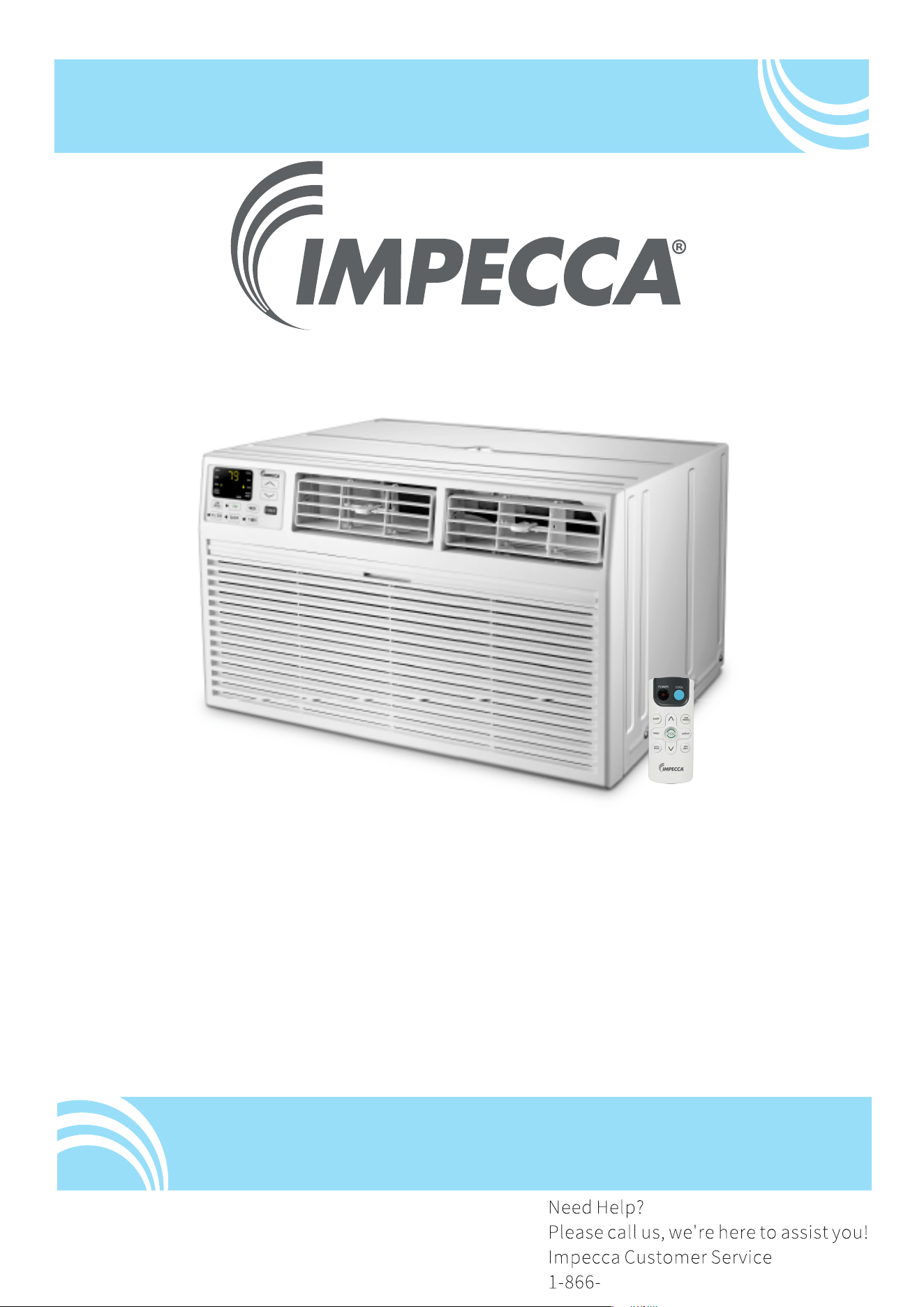
Through-The-Wall Air ConditionerAi
User Manual
Models:
ITAC08-LSA23
ITAC10-LSA23, ITAC10-LSB24
ITAC12-LSA23, ITAC12-LSB24
ITAC14-LRB24
v. 0.7
www.impecca.com

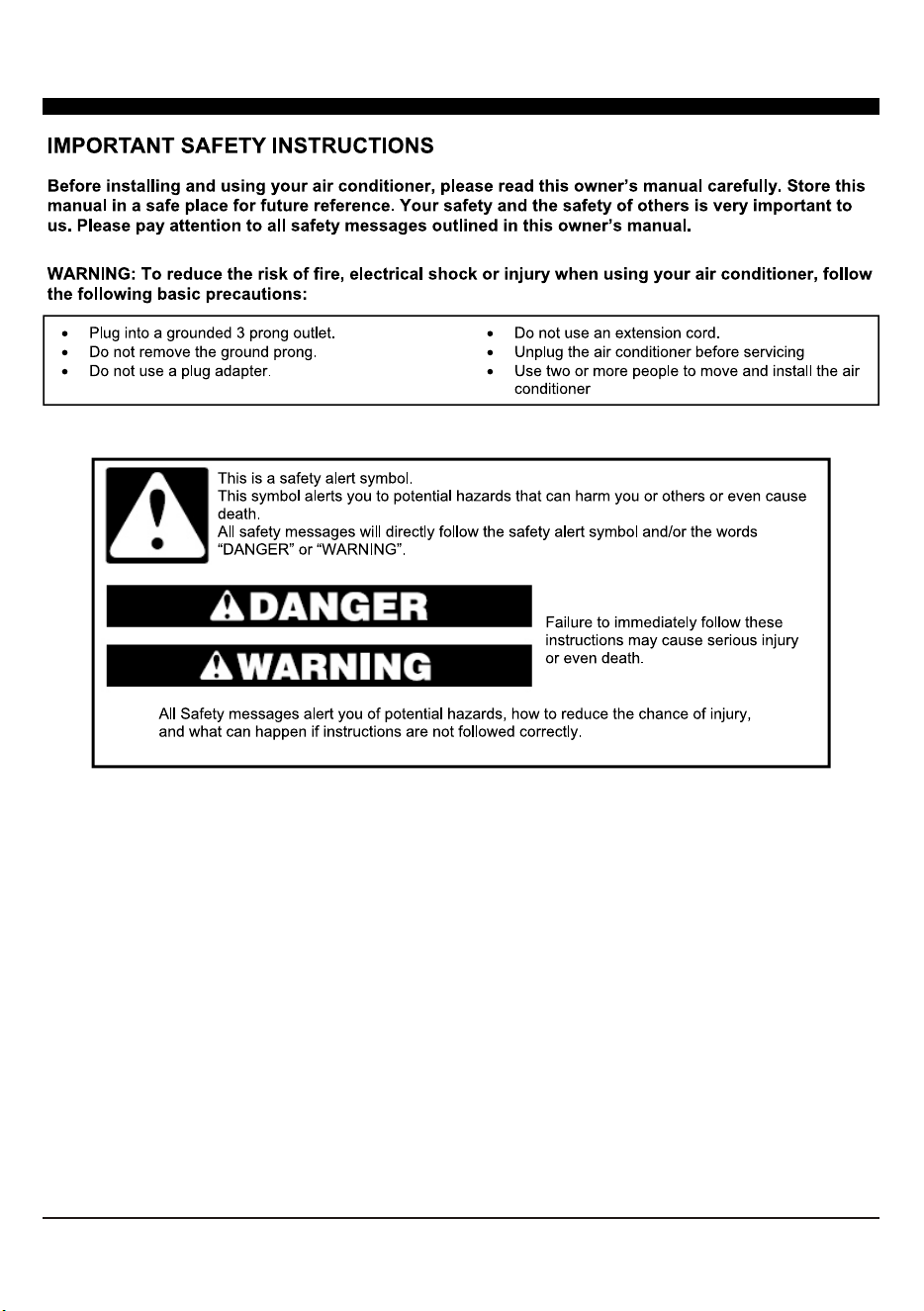
INTRODUCTION
IMPORTANT SAFETY INSTRUCTION ...........................................................................
...................................................................................
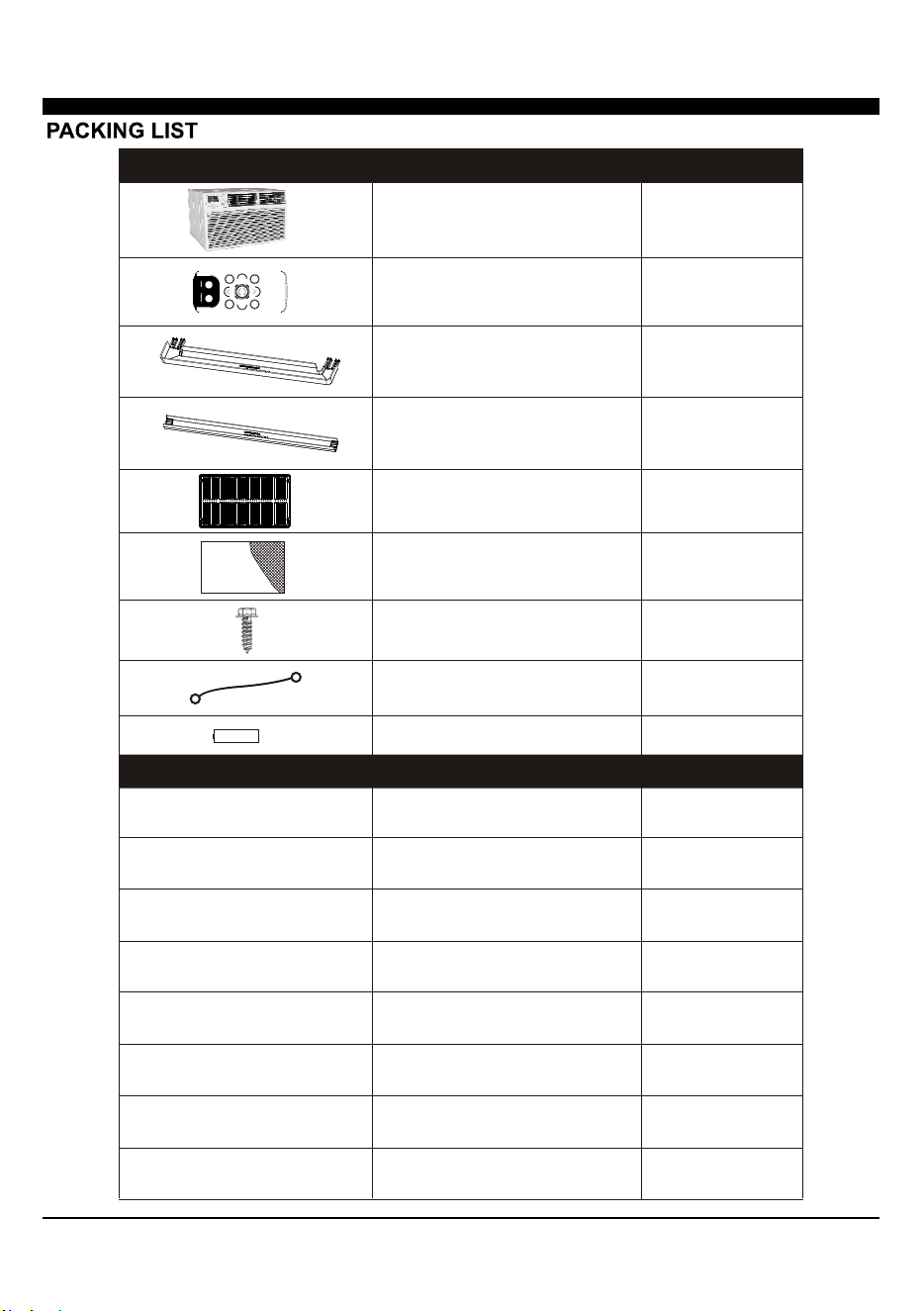
PACKING LIST ............................................................................................................
INSTALLATION & ASSEMBLY INSTRUCTIONS ..............................................................
USING YOUR AIR CONDITIONER ................................................................................
........................................................................
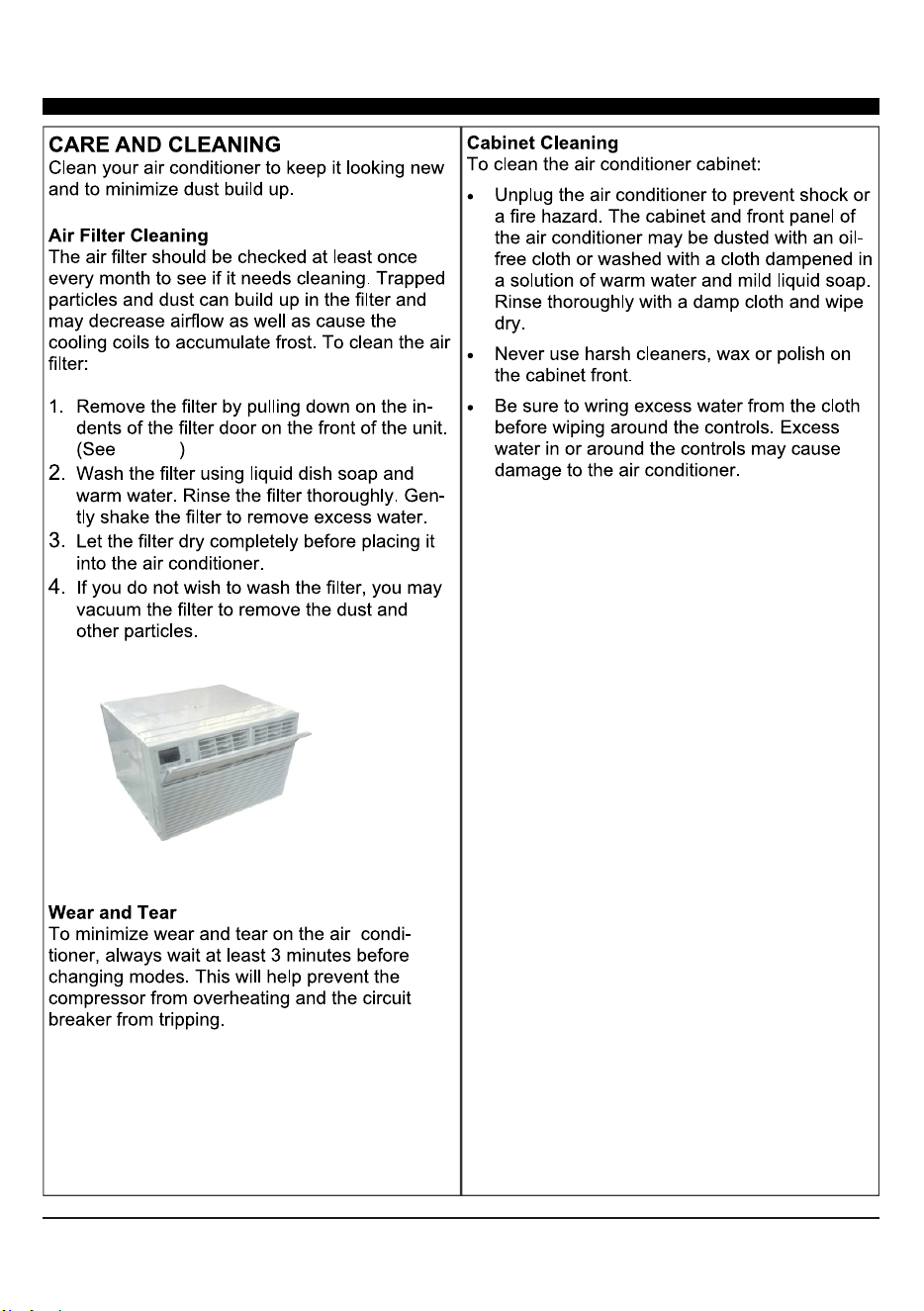
CARE AND CLEANING ................................................................................................
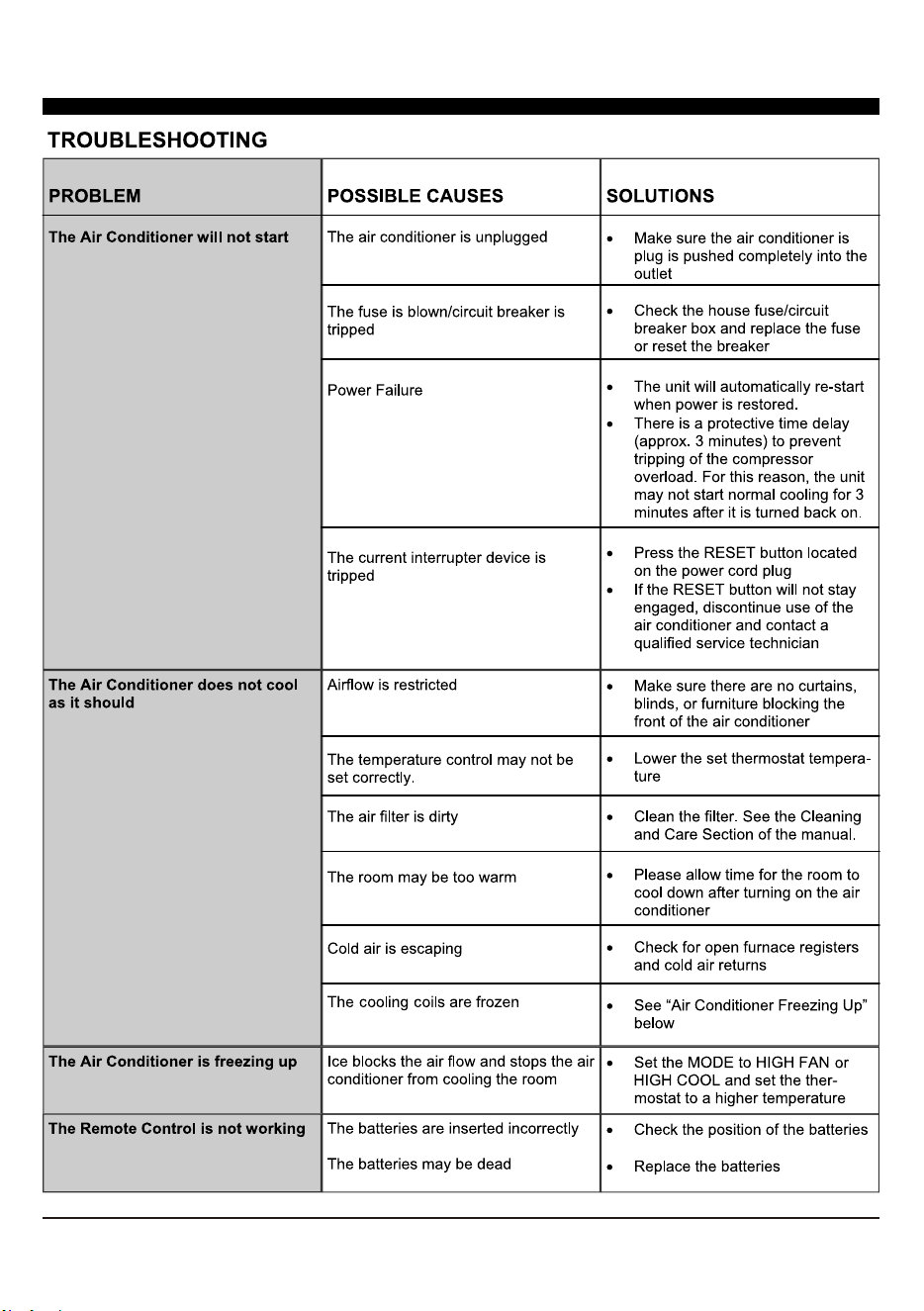
TROUBLESHOOTING .................................................................................................
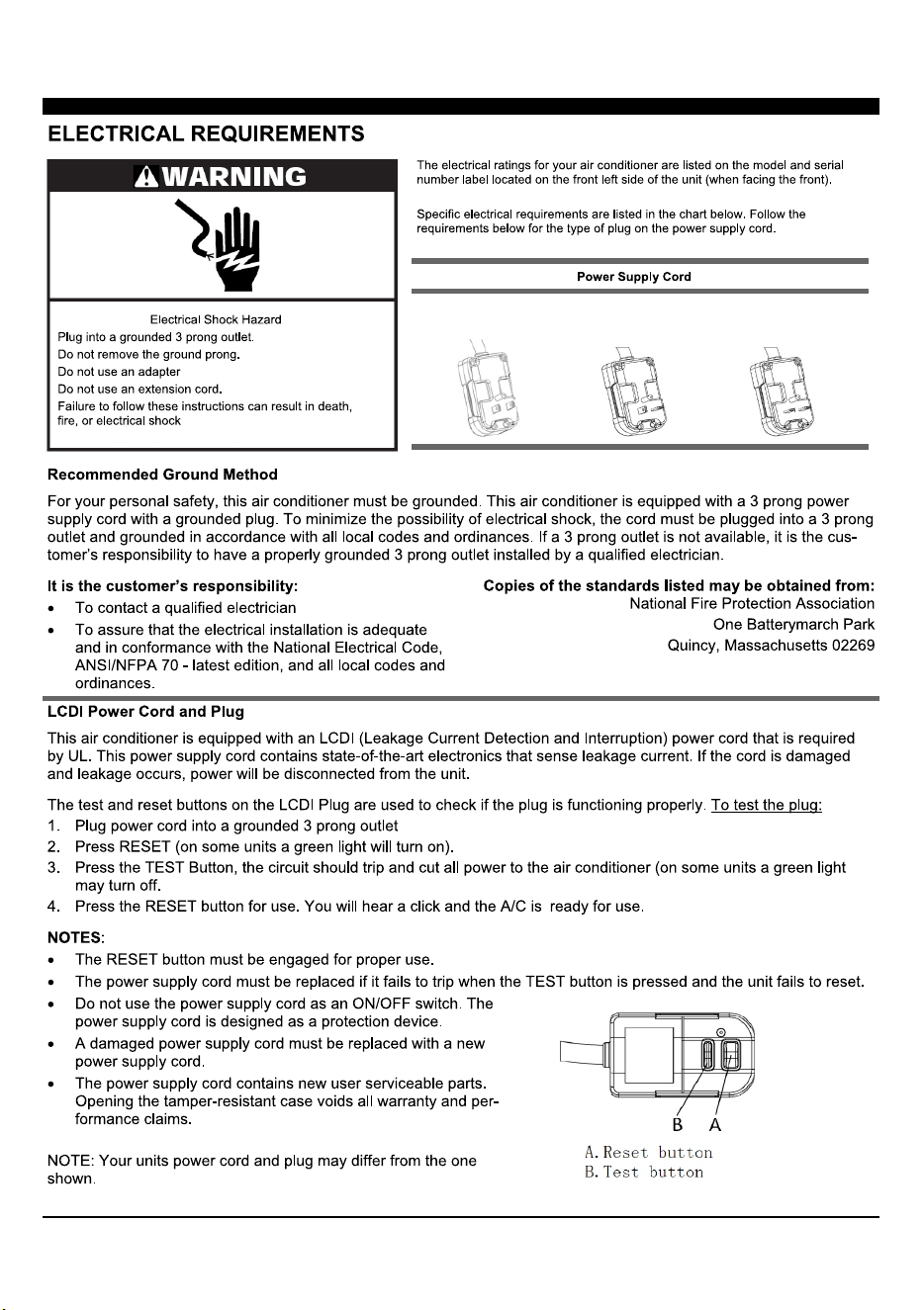
ELECTRICAL REQUIREMENTS
OPERATING YOUR AIR CONDITIONER
INTRODUCTION TO REFRIGERANTS R32 ...................................................................
1
2
3
5
6
9
11
12
13
1
2
8K/10K/12K-115V
Cooling
8K/10K/12K/14K
Cooling & Heating
10K/12K/14K-230V
Cooling
INTRODUCTION TO REFRIGERANTS R32
The refrigerants used for air conditioners are environmentally friendly hydrocarbons R32. This kind of erant is
combustible and odorless. Moreover, it can burn and explode under certain condition. However, there will be no
risk of burning and explosion if you comply with the following table to install your air conditioner in a room with
an appropriate area and use it correctly.
Compared with ordinary refrigerants, Refrigerant R32 is environmentally friendly and do not destroy the ozone
sphere and that its value of greenhouse effect is also very low.
This appliance is not intended for use by persons (including children) with reduced physical, sensory or mental
capabilities, or supervision or instruction concerning use
of the appliance by a person responsible for their safety. Children should be supervised to ensure that they do not
play with the appliance.
Unit operation limits: Outdoor side 61~110, 80%RH, indoor side 61~90, 80%RH.
Introduction to Refrigerants R32
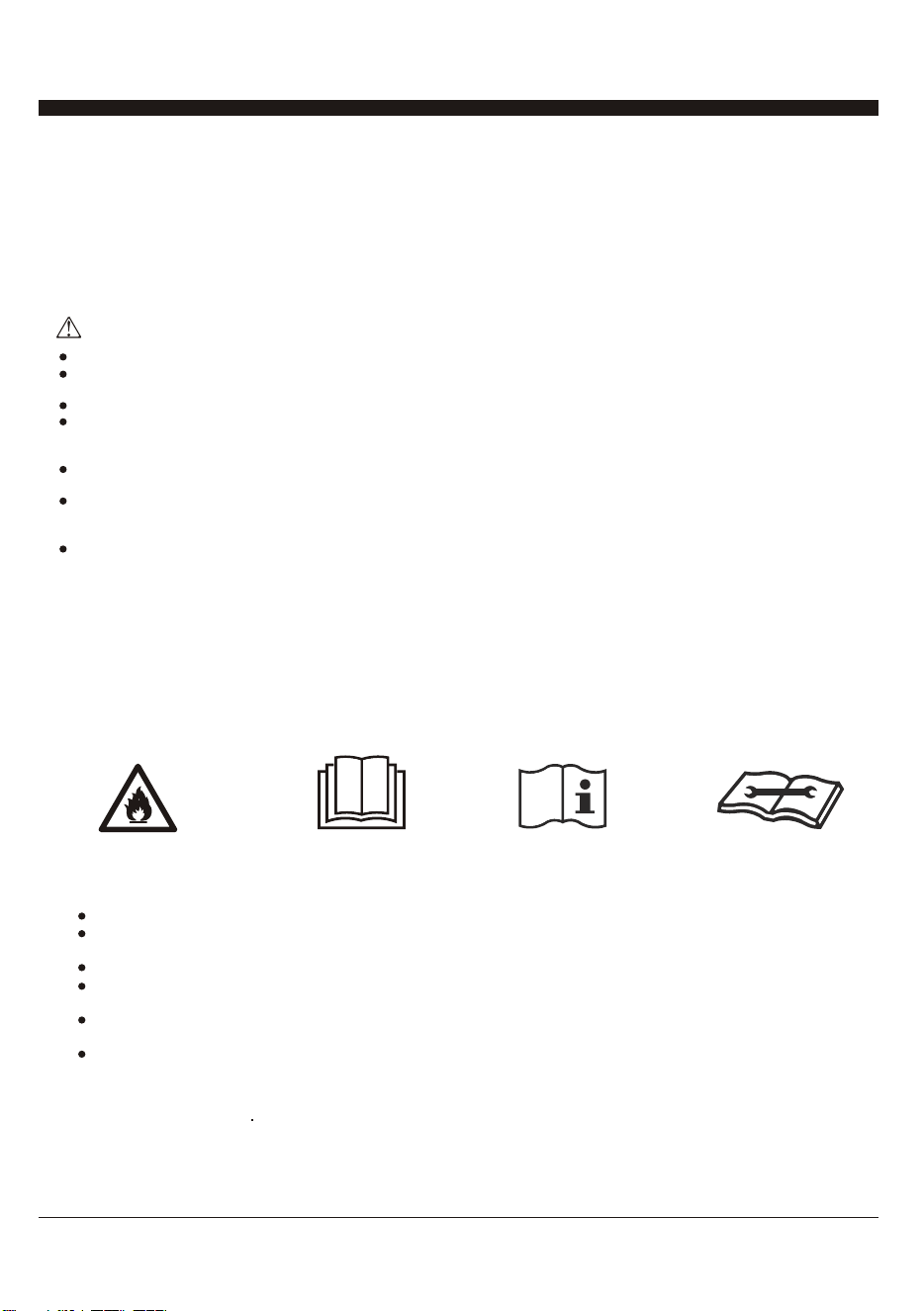
Please read the manual before installation, using, maintenance.
Do not use means to accelerate the defrosting process or to clean, other than those recommended by the
manufacturer.
Do not pierce or burn the appliance.
The appliance shall be stored in a room without continuously operating sources (for example: open flames, an
operating ignition gas appliance o r an operating electric heater.) Please contact the nearest after-sale service
center when maintenance is necessary.
At the time of maintenance, the maintenance personnel must strictly comply with the Operation Manual provided
by the corresponding manufacturer and any nonprofessional is prohibited to maintain the air conditioner.
The handling, installation, storage, servicing and disposal must comply with the provisions of gas-related national
laws and regulations, and also national wiring
regulation.
It is necessary to clear away the refrigerant in the system when maintaining or scrapping an air conditioner. Be
aware that refrigerants may not contain an odour.
Before installing the appliance, you must read the manual carefully to get the safety information and notes.
When filling the combustible refrigerant, any of your rude operations may cause serious
injury or injuries to human body or bodies and object or objects.
A leak test must be done after the installation is completed.
It is a must to do the safety inspection before maintaining or repairing an air conditioner using combustible
refrigerant in order to ensure thatthe fire risk is reduced to minimum.
It is necessary to operate the machine under a controlled procedure in order to ensure that any risk arising from
the combustible gas or vapor during the operation is reduced to minimum.
Requirements for the total weight of filled refrigerant and the area of a room to be equipped with an air
conditioner.
Warning
3
1. Site Safety
3. Installation Safety
Please note:
Using Your Air Conditioner
The installation site should be in a well-ventilated condition.
The sites for installing and maintaining an air conditioner using Refrigerant R32 should be free from open fire
or welding, smoking, drying oven or any other heat source higher than 548 C/1018F which easily produces
open fire.
When installing an air conditioner, it is necessary to take appropriate anti-static measures such as wear anti-
static clothing and/or gloves.
It is necessary to choose the site convenient for installation or maintenance wherein the air inlets and outlets
of the indoor and outdoor units should be not surrounded by obstacles or close to any heat source or
combustible and/or explosive environment.
If the indoor unit suffers refrigerant leak during the installation, all the personnel should go out till the
refrigerant leaks completely for 15 minutes. If the product is damaged, it is a must to carry such damaged
product back to the maintenance station and it is prohibited to weld the refrigerant pipe or conduct other
operations on the user's site.
It is necessary to choose the place where the inlet and outlet air of the indoor unit is even.
It is necessary to avoid the places where there are other electrical products, power switch plugs and sockets,
kitchen cabinet, bed, sofa and other valuables right under the lines on two sides of the indoor unit, and also
prevent mechanical damage from occurring.
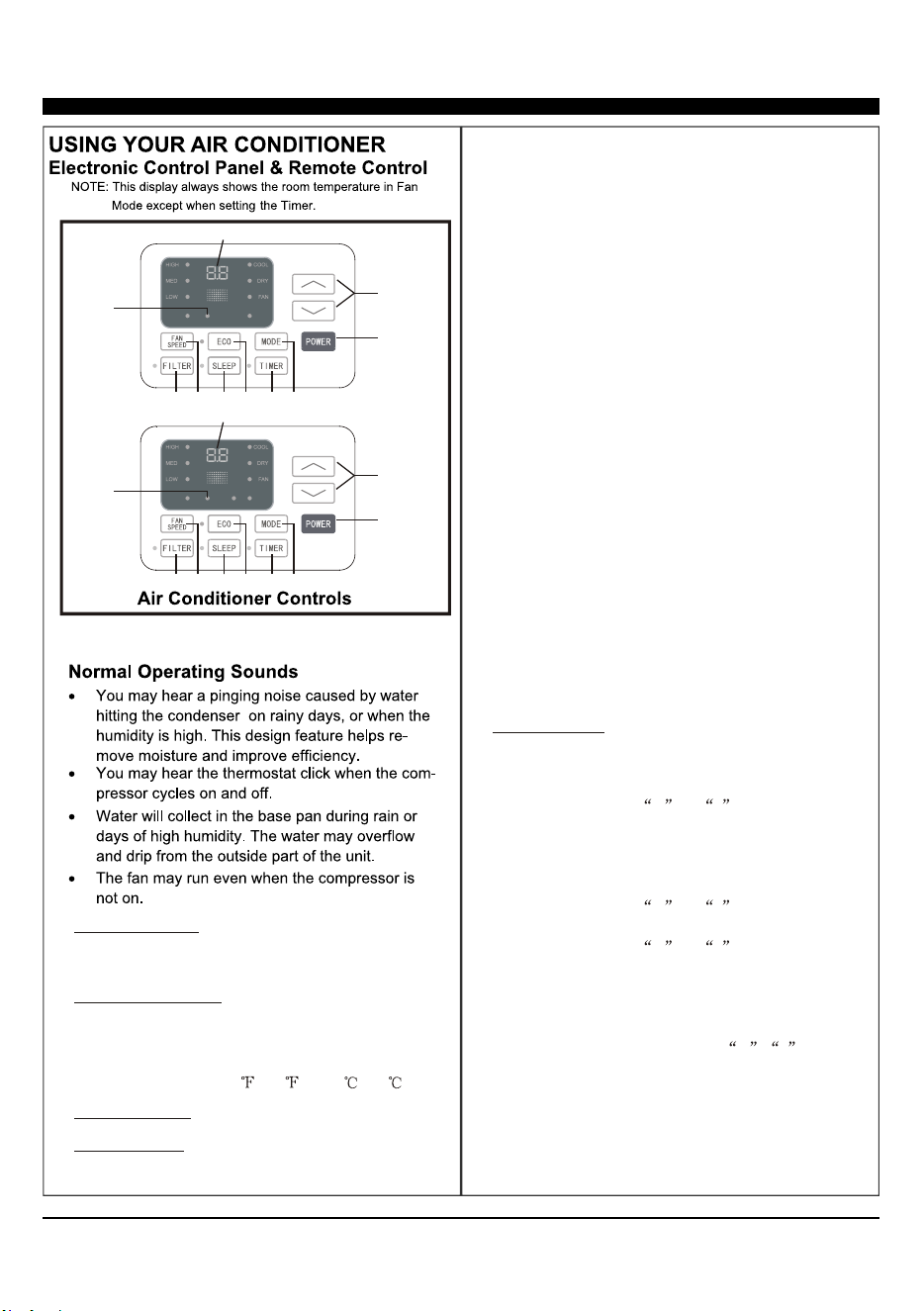
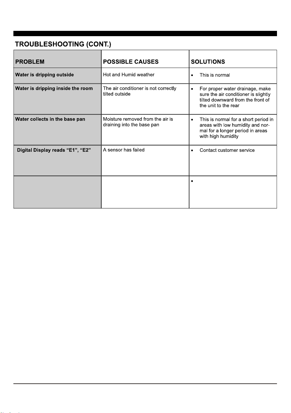
Normal Operating Sounds
You may hear a pinging noise caused by water hitting the condenser, on rainy days, or when the
humidity is high. This design feature helps remove moisture and improve efficiency.
You may hear the thermostat click when the compressor cycles on and off.
Water will collect in the base pan during rain or days of high humidity. The water may overflow and
drip from the outside part of the unit. The fan may run even when the compressor is not on.
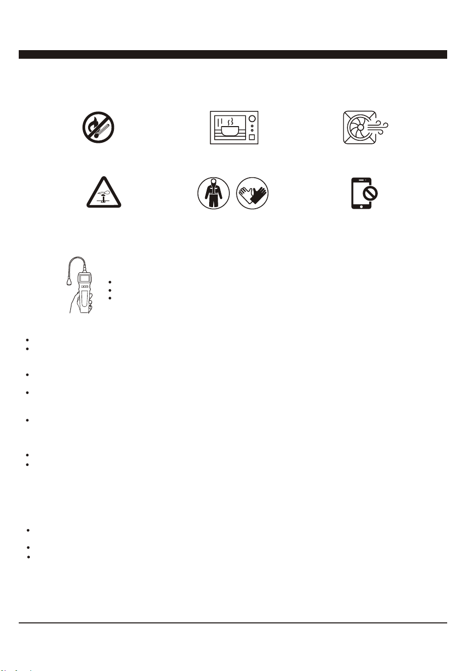
Open Flames Prohibited
Mind Static Electricity
Refrigerant Leak Detector
Appropriate Installation Location
The left picture is the schematic diagram of a refrigerant leak detector
Must Wear Protective Clothing
and anti-static gloves
Open Flames Prohibited
Ventilation Necessary
Don't use mobile phone
4
1/2" Long Hex-head Screw
Grouding wire with tooth washer
Through-The-Wall Air Conditioner
Remote Controll
Trim Frame 1 (Left&Right legs)
Trim Frame 2 (Top&Bottom legs)
Grille Aluminum
Rear plastic net
PAPT QUANTITYIMAGE
PAPT QUANTITYDimension
Seal sponge1’’x3/4’’x14’’ 2
Seal sponge1’’x3/8’’x14’’ 2
Seal sponge1’’x3/8’’x25’’
3
Seal sponge1’’x1 1/2’’x25’’ 3
Seal sponge1’’x1 1/2’’x14’’ 2
Seal sponge1’’x1 1/2’’x84’’
1
Seal cotton3 3/4’’x1 1/2’’x4’’ 4
Seal cotton3/4’’x1 1/2’’x17’’ 2
4
1
1
1
2
2
1
1
Battery
2
5
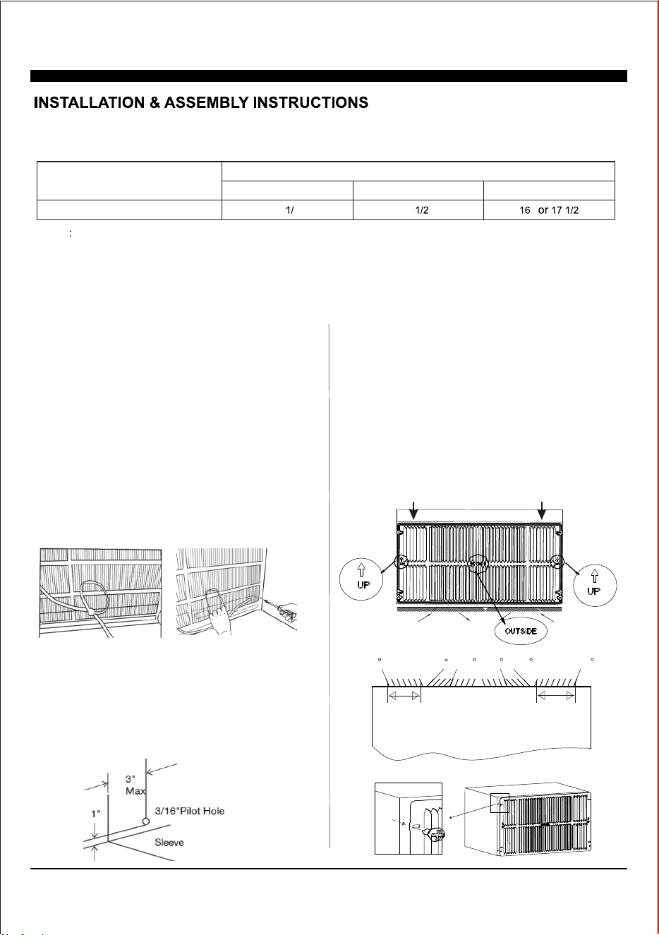
Condition1: Install the back grille to the Wall-sleeve (Prior Suggestion)
1, Identify the wall-sleeve brand for your preparing, from the below chart.
Type
Wall-sleeve Dimensions
Height Width
Depth
Standard Dimension
15 4’’
25 ’’
’’ ’’
NOTE
a, All wall sleeves used to mount the new air conditioner must be in sound structural condition and have a rear grille
that securely attached to the sleeve, or rear flange that serves as a stop for the air conditioner.
b, If you choose other wall-sleeve, be sure the dimension is suitable for the product.
c, The wall-sleeve you selected must be installed fasten to the wall with screw.
d, When do the performance testing, we suggest cancel the wall-sleeve, and install the new back grille with the new
unit, to avoid the wrong installation worse affect.
2, Prepare the Wall-sleeve before installation the unit.
(1) Remove old Air Conditioner from wall sleeve and pre-
pare as followings:
a, Clean interior (Re-stick the seals if necessary).
b, Check the wall sleeve be securely fastened in wall be-
fore installing. Add more nails or screws if needed.
c, Repair painted surface if needed.
(2) Remove the back grille.
Important: The old intake grille must be removed and re-
placed by the dual intake grille included with the TTW unit.
Warning: When removing the grille, protect from falling by
securing with a leash. Fasten by strapping looped through
the grille and secured with a knot. Holding the grille by the
leash with one hand the retaining screws can be removed
and the grille can be brought inside through the front of the
sleeve.
(3) Check the grounding wire hole.
a, If it does not exist, drill a 3/16'' pilot hole through the left
hand side of the sleeve, in a clear area about 3 inches max
deep from the front edge as below.
b, Fasten the grounding wire with screw to the drilled hole,
and pull the loose end of the ground wire out of the front of
the sleeve and bend it away from the opening. This will be
attached to the air conditioner once installed.
3, Replace the back grille.
a, Remove the old grille, and install with the dual intake
coming with the TTW unit. Take attention the remark on
the new back grille (if it appears).
b, Put the [OUTSIDE] remark toward to the back side of
wall-sleeve, and let the arrow remark toward upside.
c, Be sure that, from the back side of the wall-sleeve,
the seven inlet opening should be at left, and the eight
inlet opening should be at right.
d, Place the grille included with your new air conditioner
towards the inside rear of the sleeve. Fasten together
with the wall-sleeve by four screws.
Left intake
Seven Opening
TOP VIEW from the unit
Right intake
Eight Opening
70
50
5070 70 70
Left intake
Seven Opening
Right intake
Eight Opening
New Dual Intake Grille
6
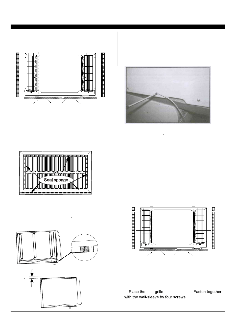
4, Install the Seal.
(1) Stick 1’’x4/5’’x13 4/5’’ sponges to the condenser side
plate, for both left and right at the back side of TTW unit.
(2) Seal the Wall-sleeve inside.
a, Seal the internal back side of wall-sleeve by sponges.
b, Seal and stick the top and bottom inside back edge by
two 1’’x1 1/2’’x25’’ long and thick sponges.
c, Seal and stick the left and right inside back edge by two
1’’x1 1/2’’x13 4/5’’ shorter and thick sponges.
IMPORTANT: Be sure that, these seal sponges will not bl-
ock the back grille inlet opening. If they effect the air-inlet
or outlet, cut them to the suitable dimension or thickness.
5, Set the tilt angle backward.
(1) Cut two suitable dimension of pearl seal cottons, and
stick to the front bottom of wall-sleeve.
(2) Be sure that, there will be a 3 tilt angle backward
of the sleeve and unit, when slide in the TTW unit.
6, Install the grounding wire.
a, Install screw end of ground wire into inside of sleeve
according to preparation instruction.
b, Remove the second screw from left side of unit, and
remove the screw plastic washer.
c, Screw the other end of the ground wire into the unit.
Make sure the toothed washer is against the cabinet.
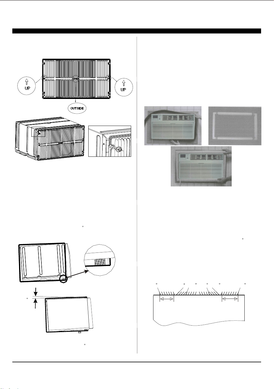
Condition2: Install the back grille to the TTW
7, Gently slide the TTW unit into wall-sleeve. Be sure that,
the unit should be a 3 tilt angle backward.
If necessary, add some pearl cotton to the unit bottom.
In case where the dual intake grille cannot be mounted di-
rectly to the sleeve. It is desirable to attach the grille to the
back of the TTW unit to the hole pre-drilled in the unit.
1, Prepare the wall-sleeve followed the Condition 1 part.
2, Stick 1’’x4/5’’x13 4/5’’ sponges to the condenser side
plate, for both left and right at the back side of TTW unit.
3, Install the back grille to the back side of the TTW unit to
the hole pre-drilled. Take attention the remark on back grille
including in the new unit, if it appears.
a, Put the [OUTSIDE] remark toward to outside, and let the
arrow remark toward upside.
b, new to the TTW unit
Wall-Sleeve
Rear
Front
3
7
Left intake
Seven Opening
TOP VIEW from the unit
Right intake
Eight Opening
70
50
5070 70 70
8
5, Set the tilt angle backward followed the Condition 1 part.
(1) Cut two suitable dimension of pearl seal cottons, and
stick to the front bottom of wall-sleeve.
(2) Be sure that, there will be a 3 tilt angle backward
of the sleeve and unit, when slide in the TTW unit.
6, Gently slide the TTW unit into wall-sleeve. Be sure that,
the sleeve and unit should be a 3 tilt angle backward.
If necessary, add some pearl cotton to the unit bottom.
4, Seal the Wall-sleeve inside. Seal the internal back side
of wall-sleeve followed condition 1 part.
Important: Be sure that, all the seal sponges will not block
the back grille inlet opening. If they effect the air-inlet or
outlet, cut them to the suitable dimension or thickness.
c, Be sure that, from the back side of the TTW, the seven
inlet opening should be at left, and the eight inlet opening
should be at right.
Trim Kit Installation Instructions
1. Install the 1''x1 1/2'' x84'' long stuffer seal between the
wall sleeve and the unit. A flat-bladed screwdriver or putty
knife is needed.
2. Assemble the trim frame by inserting the top and bottom
pieces into side pieces and snapping into place.
3. Pull the cord through the trim frame and slide the trim
over the unit until flush with the wall.
Important: Be sure that, the gap between wall-sleeve and
unit, is well sealed by sponge all around. If necessary, add
some extra sponge and adhesive tap to fill it.
Energy saving suggestion: In order to reach the maxi-
mum energy saving and comfortable, it is necessary to
use an appropriately sized cover to provide additional
insulation and air sealing when the unit is not in use
during the off-using-season.
Testing Installation Instructions
1. When do the performance testing, we suggest cancel the
wall-sleeve, and install the new back grille to the new unit,
to avoid the wrong installation worse affect.
2. Install the back grille to the unit following Condition 2 part.
Use sponge and adhesive tap to fill all the gap around betw-
een the grille and TTW unit. Cut the sponge to suitable dim-
ension, be sure that, they will not effect the air-inlet or outlet.
3. Set the tilt angle, let the sleeve and unit be a 3 tilt angle
backward to outdoor side.
4. Set the indoor air-outlet louver at the center position, both
horizontal and vertical direction.
5. Add enough water to the outside chassis to let the heating
exchange of condenser be the best condition.
6. Check whether the back grille opening angle is well or not,
if necessary, repair or replace it.
Wall-Sleeve
Rear
Front
3
9
1. Without timer setting, the set
temperature will be displayed.
Time will be displayed under timer setting. the
Digital Display:
+ and - Button:2. Use these buttons on the
control panel and remote to increase or decrease
the Set Temperature or Timer.
Temperature range: 61 ~88 or 16 ~31 .
Long press the down
button 3s can override the dr mode.
3. Turn the air conditioner on and off.Power Button:
Press the mode button to cycle
through the various modes: Cool, Dry, Fan and
Auto, or Heat.
4. Mode Button:
Use these buttons on the control
panel and remote to set the Timer.
Timer Off: The timed stop is programmed by
pressing TIMER button. Set the rest time by
pressing the button + or - until the rest
time displayed is to your then press
TIMER button again.
Timer On: When the unit is off, press TIMER
button at the first time, set the temperature with
pressing the button + or - . Press TIMER
button at the second time, set the rest time with
pressing the button + or - . Press TIMER
button at the third time, confirm the setting, then
the rest time to next automatical switching-on
could be read on the display of the machine.
Note: It can be set to automatically turn off or on in
0.5-24 hours. Each press of the +-
buttons will increase or decrease the timer. The
Timer can be set in 0.5 hours increment below 10
hours and 1 hour increment for 10 hours or above.
The SET light will turn on while setting.
To cancel the set function, press the TIMER
button again.
liking
the
5.
Timer Button:
Cool Mode: The cooling function allows the air
conditioner to cool the room and at the same time
reduces . Press the MODE button to
activate the cooling function. To optimize the
function of the air conditioner, adjust the
temperature and the speed by pressing the button
indicated.
Dry Mode: This function reduces the humidity of
the air to make the room more comfortable. Press
MODE button to set the DRY mode. An automatic
function of alternating cooling cycles and air fan
is activated.
Fan Mode: The conditioner works in only
ventilation. Press MODE button to set the FAN
mode. With pressing FAN SPEED button the
speed changes in the following sequence: Hi, Med
and Lo in FAN mode.
air humidity
the
Auto Mode: In AUTO mode the unit automatically
chooses the fan speed and the mode of operation
(COOL,HEAT,or FAN). In this mode the
temperature are set automatically according to
the room temperature (tested by the temperature
sensor which is incorporated in the indoor unit.).
Heat Mode: The heating function allows the air
conditioner to heat the room. Press the MODE
button to activate the heating function. To optimize
the function of the air conditioner, adjust the
temperature and the speed by pressing the button
indicated.
1
2
3
4
5
6
7
8
9
AUTO
SPEED
AUTO
MODE
1
2
3
4
5
6
7
8
9
HEAT
AUTO
SPEED
AUTO
MODE
For Cooling model
For Heating model
NOTE: * means only available for WIFI modes, For more
information, please see the WIFI manual.
WIFI
WIFI
WIFI
Symbol*
WIFI
Symbol*
10
When the unit is in ECO mode, the
light will turn on. In ECO mode, the unit will turn-off
once the room is cooled to the user set temperature.
The unit will turn back on when the room temperat-
ure rises above the user set temperature.
Before the compressor starts, the fan motor will run
for a while, then it will stop for awhile, It will repeat
to provide a much more comfortable feeling and
save energy.
6. ECO Button:
Press the SLEEP button, all the
display lights will turn off after a while, but the
Sleep Light is always on. In SLEEP mode, the
airconditioner will automatically adjust the
temperature and fan speed to make the room more
comfortable during the night. The set temperature
will automatically raise or decrease based on the
room temperature and the duration of sleep.
7. Sleep Button:
Press the FAN SPEED button
to choose the fan speed options. You can choose
Hi, Med, Lo or auto speed in COOL mode and
choose Hi, Med, Lo in FAN mode.
8. Fan Speed Button:
9.
When the Filter Check light is off,
When the Filter Check light is on,
the light by pressing the Filter Check button. After
the fan motor works for 500 total hours, the Filter
Check light will turn on to remind the user to clean
the filter.
it isn't necessary to press the Filter Check button.
you can turn off
Filter Button:
10.
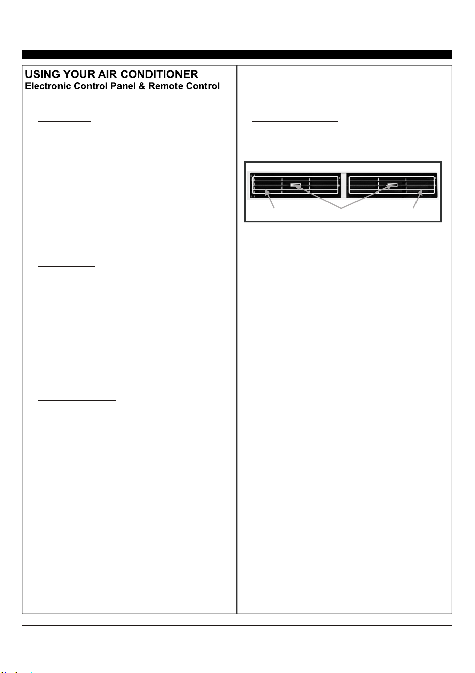
To direct the airflow, use the
horizontal wheel to control the horizontal direction
and the air deflector to control the vertical
direction.
Directional Louvers:
horizontal wheelair deflector air deflector
When the unit is in ECO mode, the light
will turn on. In ECO mode, the unit will turn-off
once the room is cooled to the user set
temperature. The fan will also be off at this
point. The unit will turn back on when the room
temperature rises above the user set
temperature.Before the compressor stars, the fan
motor will run for 20s, then it will stop for 10minutes
-and will repeat to provide a much more
comfortable-feeling and save energy.
Press the Fan Only button to FAN
ONLY mode.
9.
10.
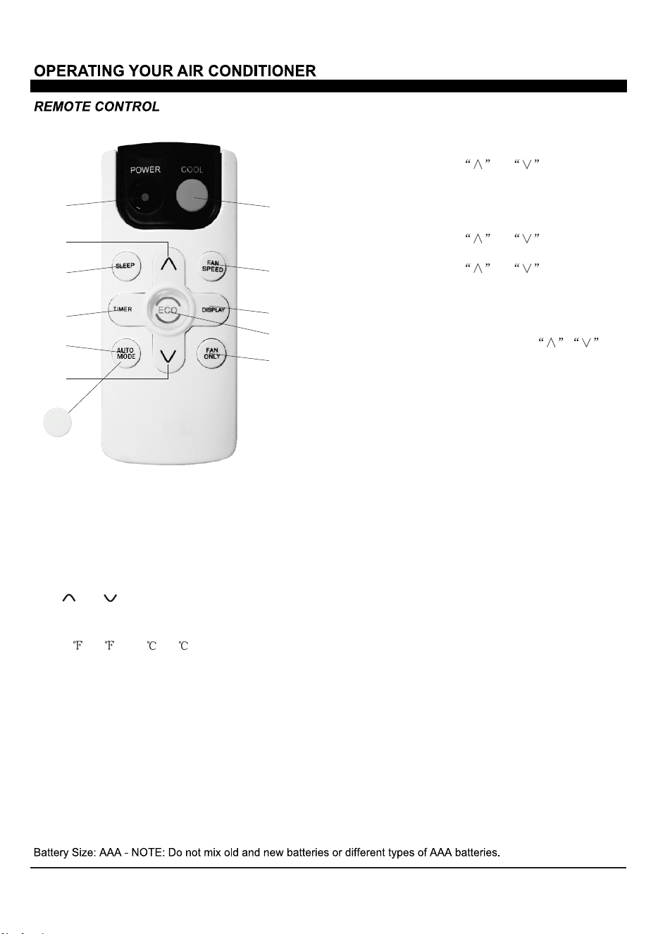
Eco:
Fan Only:
Press the FAN SPEED button to
choose the fan speed options. You can choose
Hi, Med, Lo or auto speed in COOL mode and
choose Hi, Med, Lo in FAN mode.
7. Fan Speed:
To press the DISPLAY button, it can
switch off/on all lights or LED display.
8. Display:
Use these buttons on the control panel
and remote to set the Timer.
Timer Off: The timed stop is programmed by
pressing
TIMER button. Set the rest time by
pressing the button or until the rest
time displayed is to your demand then press
TIM
ER button again.
Timer On: When the unit is off, press TIMER
button at the first time, set the temperature with
pressing the button or . Press TIMER
button at the second time, set the rest time with
pressing the button or . Press TIMER
button at the third time, confirm the setting, then
the rest time to next automatical switching-on
could be read on the display of the machine
.
Note: It can be set to automatically turn off or on
in 0.5-24 hours. Each press of the
butt
ons will increase or decrease the timer. The
Timer can be set in 0.5 hours increment below
10 hours and 1 hour increment for 10 hours or
above. The SET light will turn on while setting
.
To cancel the setted function, press the TIMER
butt
on again.
5. Timer:
In AUTO mode the unit automatically
chooses the fan speed and the mode of operation
(COOL,or FAN).In this mode the fan speed
and the temperature are set automatically according
to the room temperature (tested by the temperature
sensor which is incorporated in the indoor unit.).
It is for cooling only model.
6.a.Auto Mode:
Press the SLEEP button, all the
display lights will turn off after a while, but the
Sleep Light is always on. In SLEEP mode, the
airconditioner will automatically adjust the
temperature and fan speed to make the room
more comfortable during the night. The set
temperature will automatically raise or decrease
based on the room temperature and the duration
of sleep.
4. Sleep:
1. Turn the air conditioner on and off.Power:
2. Press the COOL button to COOL mode.Cool:
and :3.
Use these buttons on the control
panel and remote to increase or decrease the
Set Temperature or Timer. Temperature range:
61 ~88 or 16 ~31 .
1
4
5
6
3
3
7
8
10
9
2
HEAT
*For mark 6 button, it is AUTO MODE for coolling only, and it is
HEAT for heating model.
b.HEAT:
Press the HEAT button to HEAT mode.
It is for heating model.
11
12
FIG.21
FIG.21
13
14
Display dr and unit without control
The air conditioner is under demand
response, only turn ON/OFF can be
actived, and the set temperature may
raise, and the compressor may stop.
It is the demand response
condition, you can wait for the
Delay time or override it by long
press down button for 3s on the
control panel.

21
COSTUMER SUPPORT
Before contacting customer support, please see the troubleshooting guide above.
Upon unpacking your air conditioner, please be sure to write down the model and serial number of your unit. This
will be needed should your unit require servicing in the future. The number is found on a barcode on the right side
of the air conditioner and on a similar barcode on the outside of the box the unit came in.
We recommend holding onto the box, but as many people do throw it away, and the air conditioner itself gets in-
stalled in a window, it can be diicult to access this serial number later.
Model number: __________________ (One of the numbers mentioned on the cover of this manual). Your exact
number is found on your box or on the rating label sticker on the right side of the unit.
Serial number (11 digits) __________________
Please keep this manual for your records!
Visit our website to contact us, find answers to Frequently Asked Questions, and for other resources which may
include an updated version of this user’s guide.
WWW.IMPECCA.COM
If you wish to contact us by phone, please be sure to have your model number and serial number ready and call us
between 9:00am and 5:00pm ET, at +1 866-954-4440.
Keep tabs on Impecca’s newest innovations & enter contests via our social network feeds:
www.facebook.com/Impecca/
www.instagram.com/impecca/
@impeccausa
© 2017 Impecca, a division of LT Inc., Wilkes Barre, PA

Impecca™ warrants this product against defects in material
and workmanship to the original purchaser as specified be-
low.
PARTS AND LABOR– if the product is determined to
have a manufacturing defect, within a period of one
year from the date of the original purchase, Impec-
ca™, at its own discretion, will repair or replace the
product parts at no charge to you in the U.S.A.
To obtain warranty service by an authorized Impecca™ ser-
vice center, please email us at: service@impecca.com to ob-
tain a Repair and Maintenance Authorization (RMA) number
and received instructions on how the repair and/or replace-
ment procedure will take place.
Any glass materials included with the appliance will
be covered for a period of 60 days from purchase.
Impecca™ specifically excludes from this warranty any
non-electric/mechanical attachments, accessories and
disposable parts including but not limited to outside case,
connecting cables, batteries and AC adapters. Impecca™ re-
serves the right to repair or replace defective products with
the same, equivalent or newer models.
We reserve the right to either repair or replace product at our
discretion. Replacement may be either new or refurbished
and while every endeavor will be made to ensure it is the
same model, if not possible it will be equal or higher spec-
ification.
Normal “Wear and Tear” is not covered by this warranty. Fur-
ther, Impecca™ hereby reserves the right to determine “Wear
and Tear” on any and all products. Tampering or opening the
product casting or shell will void this warranty in its entirety.
Exclusions: This warranty does not cover the following:
1. Any product that has a defaced or covered serial num-
ber.
2. Products that have been transferred to a second owner.
3. Rust on the interior or exterior of the unit.
4. Products listed as “As-Is” or “Refurbished.”
5. Food loss due to any product failure.
6. Window air conditioners installed in a wall.
7. The product if used in a commercial setting.
8. Service calls that do not involve product malfunction.
9. Service calls for a product ruined by not following the
provided instructions.
10. Service calls to correct improper installation.
11. Costs associated with making the product accessible
for servicing (including but not limited to removal of
trim/molding/cabinetry, etc.)
12. Service calls to replace any consumables such as light
bulbs, filters, etc.
13. Surcharges that may apply to service calls on weekends,
nights, holidays. Damages to the finish of appliance or
household furnishings due to installation of appliance.
14. Damages caused by any of the following: Acts of God;
fires; misuse; accidents; incorrect power supply; service
performed by unauthorized persons; use of non-genu-
ine Impecca parts, etc.
ALL IMPLIED WARRANTIES, INCLUDING IMPLIED WARRAN-
TIES OF MERCHANTABILITY AND FITNESS FOR A PARTICU-
LAR PURPOSE ARE LIMITED IN DURATION TO 1 YEAR FROM
THE DATE OF THE ORIGINAL RETAIL PURCHASE OF THIS
PRODUCT.
THESE WARRANTIES AND REMEDIES ARE THE SOLE AND
EXCLUSIVE WARRANTIES AND REMEDIES IN CONNECTION
WITH THE SALE AND USE OF THE PRODUCT. NO OTHER
WARRANTIES, ORAL OR WRITTEN, EXPRESSED OR IMPLIED,
ARE GIVEN.
IMPECCA™ IS NOT RESPONSIBLE OR LIABLE FOR ANY DAM-
AGE, WHETHER SPECIAL, INCIDENTAL, CONSEQUENTIAL,
DIRECT OR OTHERWISE, OR WHETHER KNOWN OR SHOULD
HAVE BEEN KNOWN TO IMPECCA™, INCLUDING LOST PROF-
ITS, GOODWILL, AND PROPERTY AND PERSONAL INJURY RE-
SULTING FROM ANY BREACH OF WARRANTY, THE INABILITY
TO USE THE PRODUCT OR UNDER ANY LEGAL THEORY IN
CONTRACT OR TORT. IMPECCA LIABILITY IS LIMITED TO THE
ACTUAL PURCHASE PRICE PAID TO THE RETAIL SELLER OF
THE DEFECTIVE PRODUCT.
No Impecca™ dealer, agent or employee is authorized to
make any modification, extension, change or amendment to
this warranty without the written consent and authorization
from Impecca™.
Some states do not allow the exclusion or limitation of im-
plied warranties or liability for incidental or consequential
damages, or do not allow a limitation on how long an im-
plied warranty lasts, so the above limitations or exclusions
may not apply to you. This warranty gives you specific legal
rights, and you have other rights, which vary from state to
state.
Note: Our Warranty center services only to Continental U.S.A.
ONE-YEAR LIMITED APPLIANCE WARRANTY (US)