PLACE THESE INSTRUCTIONS ADJACENT TO HEATER AND NOTIFY OWNER TO KEEP FOR FUTURE REFERENCE.
KEEP THIS MANUAL IN THE POCKET ON HEATER FOR FUTURE REFERENCE WHENEVER MAINTENANCE ADJUSTMENT OR SERVICE IS
REQUIRED.
PRINTED 0725 100394452_2000597326B
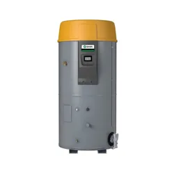
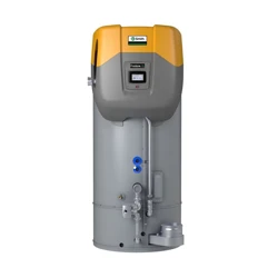
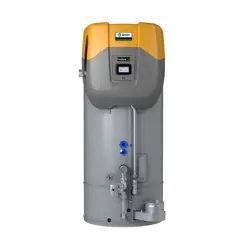
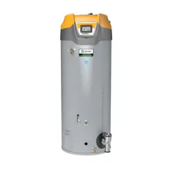
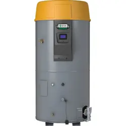
Instruction Manual
HIGH-EFFICIENCY COMMERCIAL GAS WATER HEATERS
LOW LEAD
CONTENT
WARNING: If the information in these
instructions is not followed exactly, a fire
or explosion may result causing property
damage, personal injury or death.
Do not store or use gasoline or other
flammable vapors and liquids in the
vicinity of this or any other appliance.
WHAT TO DO IF YOU SMELL GAS:
Do not try to light any appliance.
Do not touch any electrical switch; do
not use any phone in your building.
Immediately call your gas supplier
from a neighbor’s phone. Follow the
gas supplier’s instructions.
If you cannot reach your gas supplier,
call the fire department.
Installation and service must be
performed by a qualified installer,
service agency or the gas supplier.
•
•
•
•
Thank you for buying this energy efficient water heater. We
appreciate your confidence in our products.
MODELS
FLEX LARGE VOLUME
220 Gal/ 250 Gal
SERIES 400/401/450/451
INSTALLATION - OPERATION - SERVICE
- MAINTENANCE -TROUBLESHOOTING
Failure to follow these instrucons and safety
messages could result in death or serious injury.
Read and understand this instrucon manual and the
safety messages herein before installing, operang or
servicing this water heater.
This manual must remain with the water heater.
⚠
WARNING
Safety Hazard
For Your Safety
AN ODORANT IS ADDED TO THE GAS USED
BY THIS WATER HEATER.

2 • High-Eciency Commercial Gas Water Heaters
CONTENTS
APPROVALS .............................................................................................3
GENERAL SAFETY INFORMATION .......................................................... 3
Do Not Operate If Damaged ................................................................3
Limiting the Risk of Scalding ................................................................3
Grounding Instructions ........................................................................3
Hydrogen Gas Flammable ....................................................................3
Important Definitions ..........................................................................4
Hazard Messages .................................................................................4
INTRODUCTION ......................................................................................8
Abbreviations Used..............................................................................8
Qualifications ....................................................................................... 8
iCOMM and BMS/EMS Compatibility ..................................................8
Building Management System .............................................................8
Leak Detection ..................................................................................... 8
AUTOMATIC WATER Shut-off Valve ...................................................... 8
Preparing for the Installation ...............................................................8
FEATURES AND COMPONENTS ............................................................ 10
Basic Operation .................................................................................10
Modulation ........................................................................................10
Blower/Burner Assembly Detail ........................................................11
Components- Top View (All Models) .................................................12
Capacities and Performance .............................................................. 14
INSTALLATION CONSIDERATIONS .......................................................15
Rough-In Dimensions .........................................................................15
Locating the Water Heater ................................................................17
Optional Terminations .......................................................................18
Hard Water ........................................................................................18
Circulation Pumps .............................................................................. 18
Insulation Blankets ............................................................................19
INSTALLATION REQUIREMENTS ..........................................................20
Gas Supply Systems ...........................................................................20
Supply Gas Regulator ......................................................................... 20
Power Supply ..................................................................................... 20
Mixing Valves ..................................................................................... 21
Dish-washing Machines .....................................................................21
Closed Water Systems .......................................................................21
Thermal Expansion ............................................................................22
Temperature-Pressure Relief Valve .................................................... 22
Condensate Drain ..............................................................................23
Combustible Material Storage ...........................................................24
Contaminated Air...............................................................................24
Air Requirements ............................................................................... 24
Fresh Air Openings For Confined Spaces ...........................................25
Massachusetts Requirements ............................................................ 28
VENTING INSTALLATION ......................................................................29
General Venting Information .............................................................29
Category IV Appliances ......................................................................30
General Venting Instructions .............................................................31
Venting Requirements .......................................................................32
COMMON VENTING...........................................................................34
Venting Installation Sequence ...........................................................34
Power Vent Installation ......................................................................34
Direct Vent Installation ......................................................................34
Vertical Termination Installation ........................................................ 36
Horizontal Termination Installation ...................................................37
Polypropylene Installations ...............................................................39
AL29-4C
®
Vent Installations ................................................................39
Concentric Termination Installation Preparation ............................... 40
Concentric Termination Installation...................................................41
Low-Profile Vent Termination installation .........................................44
Venting Arrangements ....................................................................... 45
Termination Clearances Sidewall Power Vent ....................................47
Termination Clearances Sidewall Direct Vent ....................................48
WATER HEATER INSTALLATION ............................................................ 49
Condensate Drain Installation ...........................................................49
Leak Detection Module Installation ................................................... 50
Supply Gas Line Installation ............................................................... 50
Gas Line Leak Testing ......................................................................... 52
Electrical Wiring .................................................................................52
T&P Valve Discharge Pipe ..................................................................54
START UP ...............................................................................................55
Prior to Start up .................................................................................55
Initial Start Up ....................................................................................55
Lighting the Water Heater .................................................................58
Supply Gas Pressure Adjustment ....................................................... 59
Checking The Firing Rate ...................................................................59
High Altitude Installations .................................................................60
TEMPERATURE REGULATION ...............................................................61
High Temperature Limit Control .......................................................61
Thermostat Control ...........................................................................61
Firing Rate Modulation ......................................................................62
High Temperature Applications .........................................................62
CONTROL SYSTEM OPERATION ...........................................................63
Limiting the Risk of Scalding ..............................................................63
Wi-Fi ..................................................................................................63
Lockout Function ...............................................................................63
Control System Overview ..................................................................63
Control System Navigation.................................................................64
User Settings & Control System Menus .............................................65
MAINTENANCE .....................................................................................77
Draining And Flushing ........................................................................ 77
Sediment Removal ............................................................................. 78
Drain Valve and Access Panels ........................................................... 79
Burner Flame Inspection ...................................................................79
Anode Rod Maintenance ...................................................................80
Temperature-Pressure Relief Valve Test ............................................80
Vent System Maintenance .................................................................81
TROUBLESHOOTING ............................................................................. 82
Startup Conditions ............................................................................. 82
Operational Conditions ......................................................................82
Installation Checklist .......................................................................... 82
Sequence Of Operation .....................................................................83
Operational Problems ........................................................................ 85
Fault And Alert Conditions .................................................................87
DIAGRAMS ..........................................................................................100
Wiring Diagrams ..............................................................................100
Piping Diagrams ...............................................................................102
High-Eciency Commercial Gas Water Heaters • 3
APPROVALS
LOW LEAD
CONTENT
GENERAL SAFETY INFORMATION
DO NOT OPERATE IF DAMAGED
DO NOT USE THIS WATER HEATER IF ANY PART HAS BEEN EXPOSED TO
FLOODING OR WATER DAMAGE
. Immediately call a qualified service agency
to inspect the water heater and to make a determination on what steps
should be taken next.
If the unit is exposed to the following, do not operate heater until all
corrective steps have been made by a qualified service agency.
1. External fire.
2. Damage.
3. Firing without water.
LIMITING THE RISK OF SCALDING
For a variety of reasons, water heaters can produce water that is much
hotter than its temperature setting. Take precautions to prevent this higher
temperature water from reaching the water fixtures.
The temperature of the water in the water
heater can exceed the thermostat se�ng and
be hot enough to cause burns.
To reduce the risk of unusually hot water
reaching the fixtures in the house, install point
of use thermosta�c mixing valves at each point
of use.
⚠
WARNING
Burn Hazard
According to a national standard ,
Performance Requirements for Water
Temperature Limiting Devices (ASSE 1070)
and many local plumbing codes,
the water heater’s gas control valve should not be used as the sole means
to regulate water temperature and avoid scalds.
A properly adjusted thermostatic mixing valve at each point of use allows
you to set the tank temperature to a higher setting without increasing
risk of scalds. A higher temperature setting allows the tank to provide
much more hot water and can help provide proper water temperatures
for appliances such as dishwashers and washing machines.
GROUNDING INSTRUCTIONS
This water heater must be grounded in accordance with the
National
Electrical Code
and/or local codes. These codes must be followed in all
cases. Failure to ground this water heater properly may also cause erratic
control system operation.
This water heater must be connected to a grounded metal, permanent
wiring system; or an equipment grounding conductor must be run with
the circuit conductors and connected to the equipment grounding terminal
or lead on the water heater.
HYDROGEN GAS FLAMMABLE
Flammable hydrogen gases can form in water pipes.
The hydrogen can explode if it is exposed to flame and
can cause severe injury or death.
Keep all igni�on sources away from faucet when
turning on hot water.
⚠
WARNING
Explosion Hazard
Hydrogen gas can be produced in a hot water system served by this water
heater that has not been used for a long period of time (generally two
weeks or more). Hydrogen gas is extremely flammable. To reduce the risk
of injury under these conditions, it is recommended that a hot water faucet
served by this water heater be opened for several minutes before using
any electrical appliance connected to the hot water system. If hydrogen
is present there will probably be an unusual sound such as air escaping
through the pipe as the water begins to flow. There should be no smoking
or open flame near the faucet at the time it is open.
Verify that the power to the water heater is turned off before performing any service procedures. The Enable/Disable switch on front
panel disables the gas valve. Electrical supply must be turned off at circuit breaker serving water heater.
4 • High-Eciency Commercial Gas Water Heaters
General Safety Information
IMPORTANT DEFINITIONS
Qualified Installer: A qualified installer must have ability equivalent to a licensed tradesman in the fields of plumbing, air supply, venting and gas supply,
including a thorough understanding of the requirements of the
National Fuel Gas Code, ANSI Z223.1/NFPA 54
as it relates to the installation of gas fired
water heaters. The qualified installer must also be familiar with the design features and use of flammable vapor ignition resistant water heaters and
have a thorough understanding of this Installation and Operating manual.
Service Agency: A service agency also must have ability equivalent to a licensed tradesman in the fields of plumbing, air supply, venting and gas supply,
including a thorough understanding of the requirements of the
National Fuel Gas Code”, ANSI Z223.1/NFPA 54
as it relates to the installation of gas fired
water heaters. The service agency must also have a thorough understanding of this Installation and Operating manual, and be able to perform repairs
strictly in accordance with the service guidelines provided by the manufacturer.
Gas Supplier: The Natural Gas or Propane Utility or service who supplies gas for utilization by the gas burning appliances within this application. The
gas supplier typically has responsibility for the inspection and code approval of gas piping up to and including the Natural Gas meter or Propane storage
tank of a building. Many gas suppliers also offer service and inspection of appliances within the building.
HAZARD MESSAGES
Your safety and the safety of others is extremely important in the
installation, use and servicing of this water heater. Many safety-related
messages and instructions have been provided in this manual and on your
own water heater to warn you and others of a potential injury hazard. Read
and obey all safety messages and instructions throughout this manual. It
is very important that the meaning of each safety message is understood
by you and others who install, use or service this water heater.
Many safety-related messages and instructions have been provided in
this manual and on your own water heater to warn you and others of a
potential injury hazard. Read and obey all safety messages and instructions
throughout this manual. It is very important that the meaning of each
safety message is understood by you and others who install, use, or service
this water heater.
This is the safety alert symbol. It is used
to alert you to potenal personal injury
hazards. Obey all safety messages that
follow this symbol to avoid possible
injury or death. Keep this manual near
the water heater.
DANGER DANGER夠夠
DANGER
indicated an imminently
hazardous situaon which, if not
avoided, will result in injury or death.
WARNING WARNING夠夠
WARNING
indicates a potenally
hazardous situaon which if not avoided
could result in injury or death.
CAUTION CAUTION夠夠
CAUTION
indicates a potenally
hazardous situaon which, if not
avoided, could result in minor or
moderate injury.
CAUTION CAUTION
CAUTION
used without the safety alert
symbol indicates a potenally hazardous
situaon which, if not avoided could
result in property damage
All safety messages will generally tell you about the type of hazard, what
can happen if you do not follow the safety message, and how to avoid
the risk of injury.
Failure to follow these instrucons and safety
messages could result in death or serious injury.
Read and understand this instrucon manual and the
safety messages herein before installing, operang or
servicing this water heater.
This manual must remain with the water heater.
⚠
WARNING
Safety Hazard
The temperature of the water in the water
heater can exceed the thermostat se�ng and
be hot enough to cause burns.
To reduce the risk of unusually hot water
reaching the fixtures in the house, install point
of use thermosta�c mixing valves at each point
of use.
⚠
WARNING
Burn Hazard
Flammable hydrogen gases can form in water pipes.
The hydrogen can explode if it is exposed to flame and
can cause severe injury or death.
Keep all igni�on sources away from faucet when
turning on hot water.
⚠
WARNING
Explosion Hazard
CAUTION
Property Damage Hazard
Over me, the tank and fings of the water heater
can begin to leak and cause water damage.
• Locate the water heater near an adequate drain
and in an area where water leakage from the
heater or connecons will not result in damage to
the area or the lower floors of the structure.
• Install the water heater in a drain pan.
General Safety Information
High-Eciency Commercial Gas Water Heaters • 5
CAUTION
Property Damage Hazard
Avoid water heater damage from pressure fluctua�ons
in closed water systems.
• Fill tank with water before operating.
• Install thermal expansion tank if necessary.
• Do not apply heat to cold water inlet.
• Contact qualified installer or service agency.
Read the instruc�on manual before installing,
using, or servicing the water heater.
• Improper use can result in fire or explosion.
• Maintain required clearances to combustibles.
⚠
WARNING
Fire and Explosion Hazard
• Do not store or use gasoline or other flammable
vapors and liquids in the vicinity of this or any other
appliance.
• Avoid all ignition sources if you smell gas.
• Do not expose water heater controls to excessive gas
pressure.
• Use only the gas shown on the water heater rating
label.
• Maintain required clearances to combustibles.
• Keep ignition sources away from faucets after
extended periods of non-use.
Read instruc�on manual before installing, using or
servicing water heater.
⚠
WARNING
Fire or Explosion Hazard
Property Damage Hazard
While the water heater is in rou�ne opera�on, it can
release hot water from the temperature-pressure relief
valve discharge pipe in quan��es that could cause
damage to the surroundings.
Locate the water heater near an adequate drain and
in an area where water from the temperature-pres-
sure relief valve discharge pipe will not result in
damage to the area or the lower floors of the
structure.
⚠
CAUTION
• Do not obstruct water heater air intake
with insula�ng blanket.
• Gas and carbon monoxide detectors are
available.
• Install water heater in accordance with the
instruc�on manual.
Breathing carbon monoxide can cause brain damage or death. Always read
and understand instruc�on manual.
⚠
WARNING
Breathing Hazard - Carbon Monoxide Gas
The temperature of the water in the water
heater can exceed the thermostat se�ng and
be hot enough to cause burns.
If you choose a higher temperature se�ng,
install thermosta�c mixing valves at each
point-of-use to help avoid scalding.
⚠
WARNING
Burn Hazard
• Overheated water can cause water tank explosion.
• A properly sized temperature and pressure relief
valve must be installed in the opening provided.
⚠
WARNING
Explosion Hazard
• Under no circumstances should the input exceed
the rate shown on the water heater’s rating label.
• Overfiring could result in damage to the water
heater and sooting.
• Gas and carbon monoxide detectors are available.
Breathing carbon monoxide can cause brain damage or death. Always
read and understand instruc�on manual.
⚠
WARNING
Breathing Hazard - Carbon Monoxide Gas
6 • High-Eciency Commercial Gas Water Heaters
General Safety Information
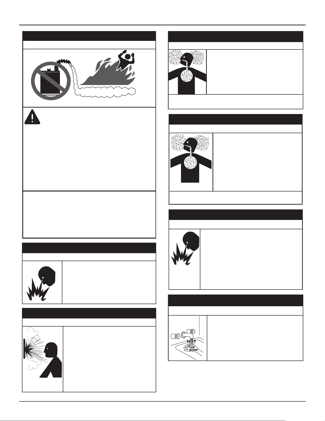
FLAMMABLES
Vapors from flammable
liquids may explode
and catch fire causing
death or sever burns.
Water heater has a main
burner and ignition device.
The ignition device:
1. Can come on at any time.
2. Will ignite flammable
vapors.
Do not use or store flammable
products, such as gasoline,
solvents, or adhesives in the
same room or area near the
water heater.
Keep flammable products:
1. Far away from heater.
2. In approved containers.
3. Tightly closed and
4. Out of children’s reach
Vapors:
1. Cannot be seen.
2. Are Heavier than air.
3. Go a long way on the floor.
4. Can be carried from other
rooms to the ignition
device by air currents.
Installation:
Do not install the water heater where flammable
products will be stored or used unless the main burner
and igniter are at least 18" (457 cm) above the floor.
This will reduce, but not eliminate the risk of vapors
being ignited by the main burner or hot surface igniter.
⚠
DANGER
Fire or Explosion Hazard
Flammable Vapors
• Do not use water heater with any gas other than
the gas shown on the rating label.
• Excessive gas pressure to gas valve can cause
serious injury or death.
• Turn off gas lines during installation.
• Contact a qualified installer or service agency for
installation and service.
⚠
WARNING
Fire and Explosion Hazard
Normal opera�on of the water heater can cause
it to become sufficiently over-heated and/or
over-pressurized that it can explode, resul�ng in
property damage, sever injury, or death.
To avoid this hazard, you must install a properly-
sized temperature-pressure relief valve in opening
provided.
• The temperature-pressure relief valve must
comply with ANSI Z21.22-CSA 4.4 and ASME
code.
• Do not plug, block, or cap the discharge line.
⚠
WARNING
Explosion Hazard
• Install water heater in accordance with
the Instruction Manual and NFPA 54 or
CAN/CSA-B149.1.
• To avoid injury, combustion and ventilation air
must be taken from outdoors.
• Do not place chemical vapor emitting products
near water heater.
Breathing carbon monoxide can cause brain damage or death. Always
read and understand instruc�on manual.
⚠
WARNING
Breathing Hazard - Carbon Monoxide Gas
• Special considera�ons must be taken with
installa�ons above 10,100 (3,078 meters).
• Please contact an A. O. Smith qualified
service agent to obtain the proper setup
and instruc�ons before ligh�ng.
• Failure to implement the proper setup will
result in improper and inefficient opera�on
of the appliance, resul�ng in produc�on of
increased levels of carbon monoxide gas in
excess of the safe limits which could result
in serious personal injury or death.
Breathing carbon monoxide can cause brain damage or death. Always read
and understand instruc�on manual.
⚠
WARNING
Breathing Hazard - Carbon Monoxide Gas
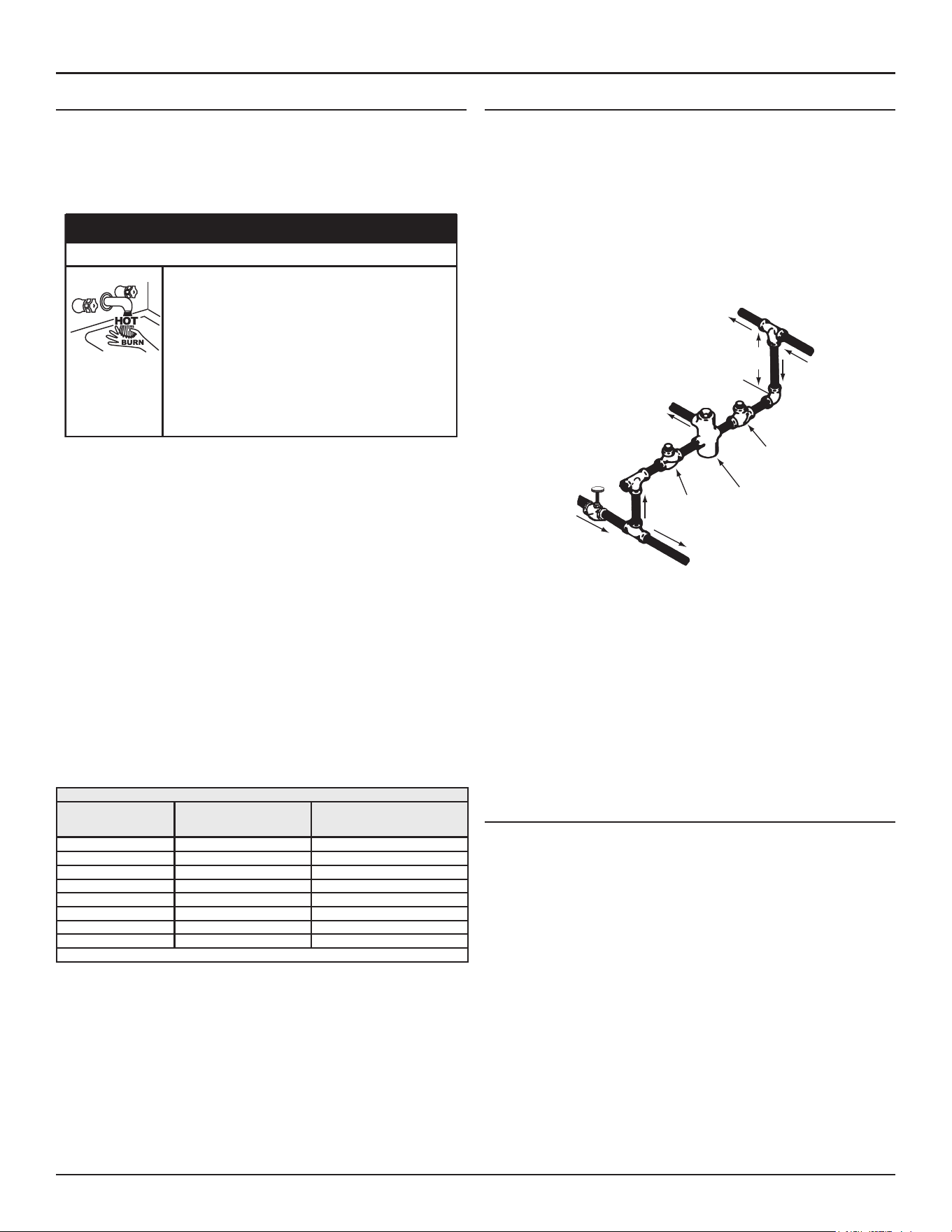
Gas piping can leak gas from fi�ngs and connec�ons if
it is not sealed properly. Gas leaks can cause fires and
explosions resul�ng in severe injury or death.
• Use joint compound or thread sealer tape compatible
with the type of gas you are using.
• Leak test all gas connections before placing the water
heater in operation.
• Disconnect gas piping at main gas shutoff valve before
leak testing.
• Install sediment trap in accordance with NFPA 54 or
CAN/CSA B149.1.
⚠
WARNING
Fire and Explosion Hazard
Burn Hazard
• The combus�on chamber and burner
sleeve and housing become very hot
during opera�on.
• Do not reach into the burner housing or
combus�on chamber if the water heater is
s�ll hot.
• Allow the water heater to cool and always
use gloves when handling the main burner.
⚠
CAUTION
General Safety Information
High-Eciency Commercial Gas Water Heaters • 7
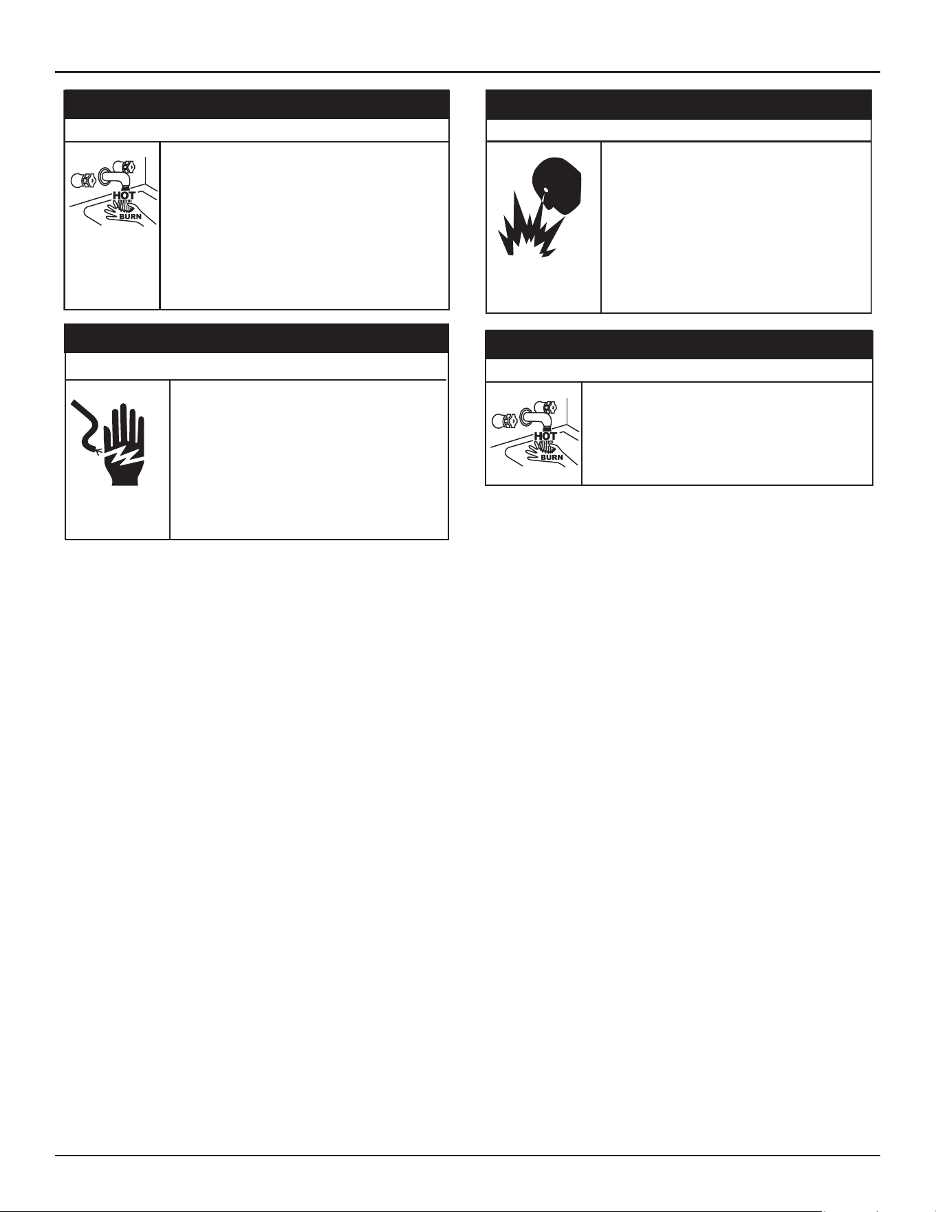
Water temperature over 52°C (125°F) can cause severe
burns instantly resul�ng in severe injury or death.
Children, the elderly and the physically or mentally
disabled are at highest risk for scald injury.
Feel water before bathing or showering.
Temperature limi�ng devices such as thermosta�c
point-of-use mixing valves must be installed when
required by codes and to ensure safe temperatures at
fixtures.
⚠
DANGER
Burn Hazard
Servicing this water heater exposes you to
electrified components that can cause severe
injury or death if you touch them.
• Turn off power at the branch circuit breaker
serving the water heater before performing any
service.
• Label all wires prior to disconnecting when
performing service. Wiring errors can cause
improper and dangerous operation.
• Verify proper operation after servicing.
⚠
WARNING
Electrical Shock Hazard
Jumping out control circuits or components can
result in property damage, personal injury or death.
• Service should only be performed by a qualified
service technician using proper test equipment.
• Altering the water heater controls and/or wiring in
any way could result in permanent damage to the
controls or water heater and is not covered under
the limited warranty.
• Any bypass or alteration of the water heater
controls and/or wiring will result in voiding the
appl
iance warranty.
⚠
WARNING
Safety Hazard
⚠
DANGER
Burn Hazard
The discharge water from the temperature-pressure
relief valve is hot enough to cause burns.
Keep clear of the temperature-pressure relief valve
discharge outlet.

8 • High-Eciency Commercial Gas Water Heaters
INTRODUCTION
Thank You
for purchasing this water heater. Properly installed and
maintained, it should give you years of trouble free service.
ABBREVIATIONS USED
Abbreviations found in this Instruction Manual include :
• ANSI - American National Standards Institute
• ASME - American Society of Mechanical Engineers
• AHRI - Air Conditioning, Heating and Refrigeration Institute
• NEC - National Electrical Code
• NFPA - National Fire Protection Association
• UL - Underwriters Laboratory
• CSA - Canadian Standards Association
QUALIFICATIONS
Qualified Installer or Service Agency
Installation and service of this water heater requires ability equivalent to
that of a Qualified Agency (as defined by ANSI below) in the field involved.
Installation skills such as plumbing, air supply, venting, gas supply and
electrical supply are required in addition to electrical testing skills when
performing service.
ANSI Z223.1:
“Qualified Agency” - “Any individual, firm, corporation or
company that either in person or through a representative is engaged in and
is responsible for (a) the installation, testing or replacement of gas piping
or (b) the connection, installation, testing, repair, or servicing of appliances
and equipment; that is experienced in such work; that is familiar with all
precautions required; and that has complied with all the requirements of
the authority having jurisdiction.”
If you are not qualified (as defined by ANSI above) and licensed or certified
as required by the authority having jurisdiction to perform a given task do
not attempt to perform any of the procedures described in this manual. If
you do not understand the instructions given in this manual do not attempt
to perform any procedures outlined in this manual.
ICOMM AND BMS/EMS COMPATIBILITY
ICOMM™
This water heater comes equipped with the iCOMM™ remote monitoring
system. It allows users to monitor critical operations and diagnose issues
remotely using the manufacturer’s water heater app (available for IOS
and Android).
The iCOMM™ system can automatically notify selected personnel via
email and or cellular phone text messages if operational problems or user
defined Alert conditions should occur. The system is expandable to meet
the needs of multiple heaters and groups of heaters.
To order or to find out more about ICC devices, Technical Support.
To connect your water heater to iCOMM, download the A. O. Smith app
from the Apple App Store or Google Play store and follow the instructions
for how to add your water heater.
BUILDING MANAGEMENT SYSTEM
This water heater is connectible to BACnet or Modbus compliant
Supervisory controls via the optional ICC BMS Gateway. This allows
connection of the water heater to local Building Management Systems
using Serial RS-485 (MS/TP) or IP connections.
LEAK DETECTION
The water heaters covered in this manual are equipped with a leak
detection device that continuously tests for the presence of water in the
immediate location of the water heater. If water is detected, it generates
an alarm.
AUTOMATIC WATER SHUT-OFF VALVE
The optional Automatic Water Shut off Valve and Valve Control Board
work in conjunction with the TRC to help reduce the risk of further water
damage if a leak is detected by the leak detection device.
PREPARING FOR THE INSTALLATION
1. Read the entire manual before attempting to install or operate the
water heater. Pay close attention to the
General Safety Information
(page 3). If you don’t follow the safety rules, the water heater may
not operate safely. It could cause property damage, injury and/or death.
• This manual contains instructions for the installation, operation,
and maintenance of the water heater. It also contains warnings
throughout the manual that you must read and be aware of.
All warnings and all instructions are essential to the proper
operation of the water heater and your safety.
• Detailed installation diagrams are also found in this manual.
These diagrams will serve to provide the installer with a
reference. It is essential that all venting, water piping, gas piping
and wiring be installed as shown.
• Particular attention should be given to the installation of
thermometers at the locations indicated in the piping diagrams
as these are necessary for checking the operation of the water
heater.
• The principal components of the water heater are identified in
Features and Components
(page 10) in this manual. Use this
reference to locate and identify various components on the
water heater.
• See
Troubleshooting
(page 82). By using this checklist the
user may be able to make minor operational adjustments and
avoid unnecessary service calls. However, service and diagnostic
procedures should be performed only by a Qualified Service
Agency.
Note:
Costs to correct installation errors are not covered under the
limited warranty. See the Commercial Water Heater Limited
Warranty Insert.
2. Be sure to turn off power when working on or near the electrical system
of the water heater. Never touch electrical components with wet hands
or when standing in water.

Introduction
High-Eciency Commercial Gas Water Heaters • 9
3. The installation must conform to all instructions contained in this
manual and the local code authority having jurisdiction. These shall be
carefully followed in all cases. Authorities having jurisdiction should be
consulted before installation begins if there are any questions regarding
compliance with local, state or national codes.
• In the absence of local codes, the installation must comply
with the current editions of the
National Fuel Gas Code
,
ANSI
Z223.1/NFPA 54
and the
National Electrical Code
,
NFPA 70
or
CAN/CSA-B149.1
, the
Natural Gas and Propane Installation Code
and
CSA C22.1
, the
Canadian Electrical Code
. All documents are
available from the Canadian Standards Association, 8501 East
Pleasant Valley Road, Cleveland, OH 44131. NFPA documents are
also available from the National Fire Protection Association, 1
Batterymarch Park, Quincy, MA 02269.
4. After reading this manual, if you have any questions or do not
understand any portion of the instructions, call the toll free number
on the back cover of this manual for technical assistance. In order to
expedite your request, please have the full Model, Serial and Series
numbers of the water heater you are working with available for the
technician. This information is located on the water heater’s rating label.
5. Carefully plan the placement of the water heater. Examine the location
to ensure that it complies with the requirements in
Locating the Water
Heater
(page 17) and the
Rough-In Dimensions
(page 15).
10 • High-Eciency Commercial Gas Water Heaters
FEATURES AND COMPONENTS
BASIC OPERATION
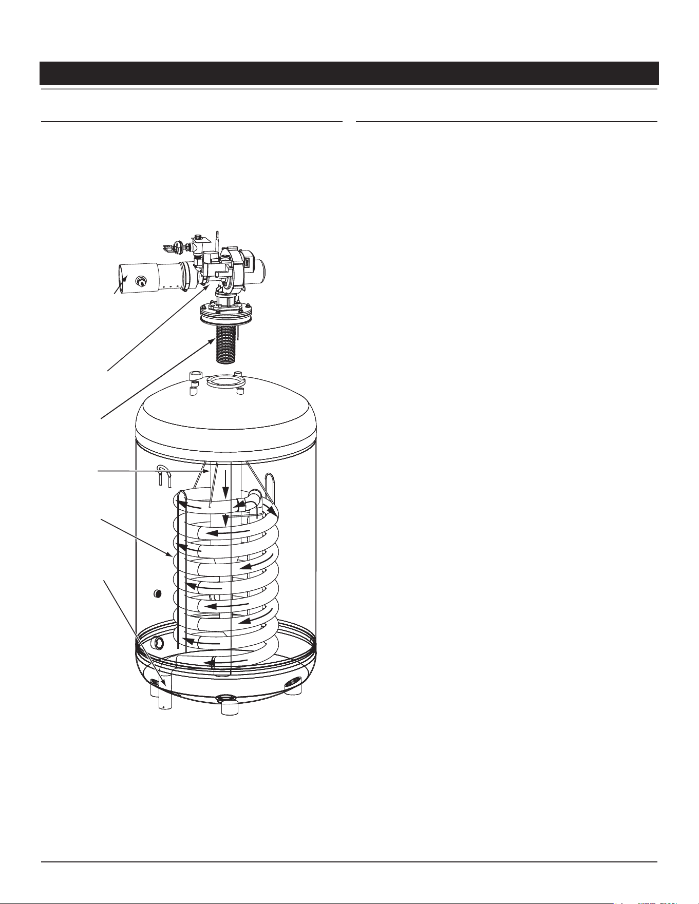
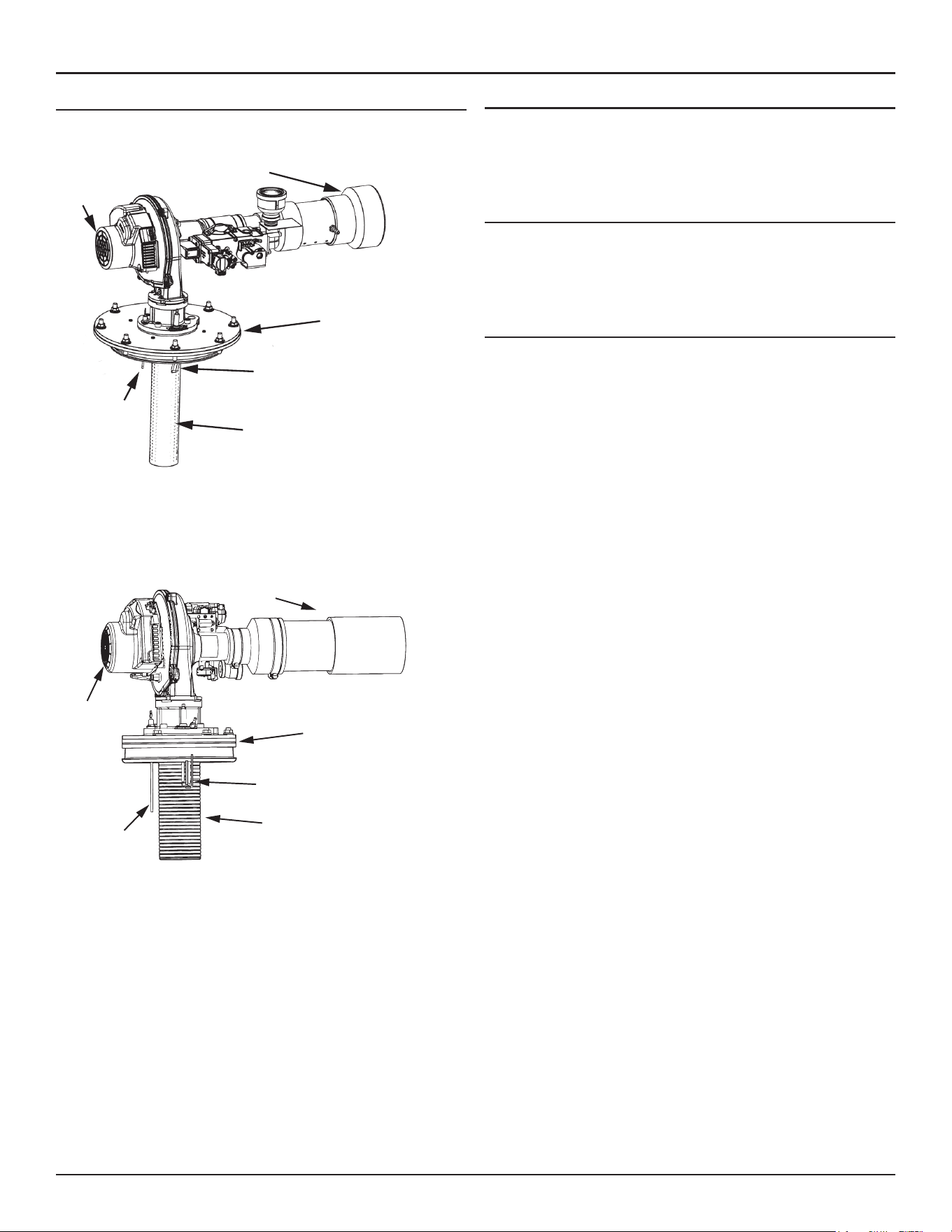
The water heaters covered in this manual have a helical coil shaped heat
exchanger that is submerged in the storage tank. The water heater’s
Main Burner is a radial design burner, it is mounted on the top and fires
downward through the heat exchanger. This is a forced draft burner; hot
burning gases are forced through the heat exchanger under pressure and
exit through the exhaust/vent connection located at the bottom of the
water heater. See
Figure 1
and
Figure 2
.
MAIN
BURNER
(radial design)
BLOWER
BURNER
ASSEMBLY
HEAT
EXCHANGER
HELICAL
COIL
VENT (exhaust)
OUTLET
INTAKE AIR
(combustion air)
CONNECTION
PVC
Figure 1. Water Heater Components
MODULATION
The water heaters covered by this manual are capable of modulating their
firing rate. The combustion blower is controlled by the TRC and CSC. The
control boards monitor the water temperature in the tank and regulate
the firing rate to achieve the target temperature set-point. The firing rate
is dictated by the hot water draw, proximity to the tank temperature set-
point, and various other temperature limitations.
Features and Components
High-Eciency Commercial Gas Water Heaters • 11
BLOWER/BURNER ASSEMBLY DETAIL
Intake Air Connection Pipe
Combustion
Blower
Assembly
Spark Igniter
Flame
Sensor
Main Burner
(radial design)
Burner Flange
220 GALLON
Intake Air Connection Pipe
Combustion
Blower
Assembly
Spark Igniter
Flame
Sensor
Main Burner
(radial design)
Burner Flange
250 GALLON
Figure 2. Blower/Burner Components
Spark Igniter
The control system energizes the spark ignition transformer with 120
VAC during the ignition cycle. The spark ignition transformer then sends
a high-voltage current to the spark igniter which in turn ignites the main
burner air/gas mixture.
Flame Sensor
The control system also monitors the flame sensor to confirm a flame is
present at the main burner. If a flame is not verified during the ignition
trial period the control system will immediately deenergize the gas valve.
See the
Sequence Of Operation
(page 83).
Gas Valve
This heater is equipped with a gas adaptive system and motor driven
throttle. It is controlled by the CSC in conjunction with the TRC.
12 • High-Eciency Commercial Gas Water Heaters
Features and Components
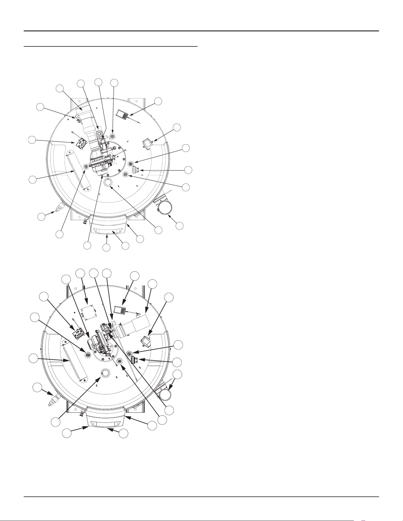
COMPONENTS- TOP VIEW (ALL MODELS)
IMPORTANT. The Enable/Disable switch listed in this manual is NOT an
"on/off" switch and does not disconnect 120 Vac power to the control
boards and other heater components.
8
6
17
10
15
3
11
2
1
14
2
12
9
7
4
5
2
16
13
18
Figure 3. Top View - 220 Gallon
17
16
4
2
15
3
11
13
14
1
2
6
9
7
10
8
5
18
2
12
Figure 4. Top View - 250 Gallon
1. Water Heater’s Enable/Disable Switch. When in the "Disabled" position
the switch removes electrical power from the gas valve so that water
heating is disabled. The display, control boards, and other electrical
components will still be energized and the display will read "Water
Heating Disabled".
2. Powered anode rods. The water heaters covered in this manual are
equipped with powered (non sacrificial) anode rods. Protective current
is fed by the control system to the titanium electrodes at the end of
each anode rod. This current flows through the water to the conductive
surfaces inside the storage tank which diminishes the corrosive effect
of water when it comes in contact with steel.
3. Control Board Enclosure. This enclosure houses the control system’s
Temperature Regulation Control (TRC 1000), Combustion and Safety
Control (CSC), and power supply. The TRC 1000 and CSC regulate water
temperature and controls all water heater functions. See
Control System
Operation
(page 63).
4. Combustion Blower Assembly includes, Gas Valve and Venturi gas
feed system.
5. 120-VAC junction box. Incoming power supply, ground connections,
and other field installed electrical connections are made here. See
Power Supply
(page 20)
and
Power Supply Connections
(page 52).
6. Water heater's gas valve.
7. Blocked Intake Air switch. Normally closed contacts that open on fall
in pressure. This switch is used to ensure intake (combustion) air to
the water heater is not restricted. The control system monitors this
switch and will disable heating operation if its contacts are open during
a heating cycle.
8. Supply gas line connection. See the requirements for gas supply systems
in
Gas Supply Systems
(page 20).
9. Vent connection (exhaust / condensate elbow) - aluminum.
10. Intake air connection - PVC.
11. Temperature-Pressure Relief Valve. See
Temperature-Pressure Relief
Valve
(page 22).
12. Main Temperature Probe, 1 of 2 temperature probes (not shown).
The water heater’s control system monitors this probe to detect water
temperature in the upper portion of the storage tank. The Upper
Temperature Probe also houses the Energy Cut-Out (ECO). This is a non
adjustable high temperature limit thermistor. See
High Temperature
Limit Control
(page 61).
13. Water outlet connection 1 1/2” NPT.
14. UIM (user interface module). The UIM includes the display circuit board
and the control system’s LCD Touch Display. Used to adjust various
user settings and view operational information. See
Control System
Operation
(page 63).
15. Spark Ignition Transformer. When energized, sends the electrical current
to the spark igniter.
16. CPAM (Powered Anode Module): Auxiliary control for the operation
of powered anodes.
17. CPAM Power Supply: Provides 120 Vac power to the CPAM.
18. Flex Memory Module (FMM) under cover: The FMM board is located inside
the plastic display enclosure. The FMM board enables an FMM device to
communicate information with the heater.
DO NOT REMOVE OR DAMAGE THE
FMM BOARD
.
Features and Components
High-Eciency Commercial Gas Water Heaters • 13
1
2
6
17
11
13
15
16
4
1
2
8
7
10
5
6
3
12
14
15
4
1
8
7
5
10
11
17
13
14
15
16
6
3
2
9
12
Figure 5. 220-Gallon Models — Left-Side and Right-Side Components
1
2
6
17
11
13
14
15
4
1
2
8
10
3
6
5
7
12
16
15
6
4
1
2
8
10
11
17
13
15
14
16
3
6
5
7
12
9
Figure 6. 250-Gallon Models — Left-Side and Right-Side Components
14 • High-Eciency Commercial Gas Water Heaters
Features and Components
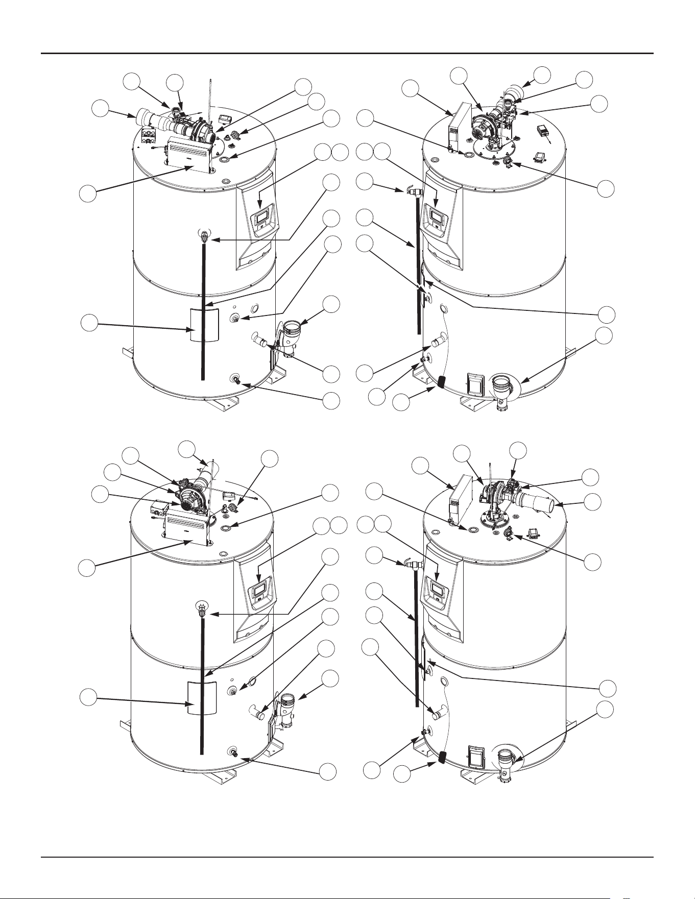
Side View Components
1. Water outlet - 1 1/2” NPT connection.
2. UIM (user interface module). The UIM includes the display circuit board
and the control system’s LCD Touch Display. Used to adjust various
user settings and view operational information. See
Control System
Operation
(page 63).
3. Flex Memory Module (FMM) under cover: The FMM board is located inside
the plastic display enclosure. The FMM board enables an FMM device to
communicate information with the heater.
DO NOT REMOVE OR DAMAGE THE
FMM BOARD
.
4. Temperature-Pressure Relief Valve. See
Temperature-Pressure Relief
Valve
(page 22).
5. Temperature-Pressure Relief Valve discharge pipe - see
T&P Valve
Discharge Pipe Requirements
(page 22)
6. Lower Temperature Probe, 1 of 2 temperature probes. The water
heater’s control system monitors this probe to detect water
temperature in the lower portion of the storage tank.
7. Water inlet - 1 1/2” NPT connection.
8. Water heater drain valve.
9. Leak Detection Module. This feature senses the buildup of water in the
vicinity of the appliance.
10. Vent Connection (Exhaust/Condensate Elbow) - aluminum.
11. Clean-out access panel, covers water heater clean-out opening and
ASME plate where applicable.
12. Blocked Exhaust (vent) switch. Normally closed contacts that open on a
rise in pressure. This switch is used to ensure the Exhaust (vent) piping
connected to the water heater is not restricted. The control system
monitors this switch and will disable heating operation if its contacts
are open during a heating cycle.
13. Intake air connection - PVC.
14. Water heater gas valve.
15. Supply gas line connection. See
Gas Supply Systems
(page 20).
16. Combustion Blower Assembly includes, Gas Valve and Venturi gas
feed system.
17. Control boards enclosure - see item 3 in
Components- Top View (All
Models)
(page 12) for description.
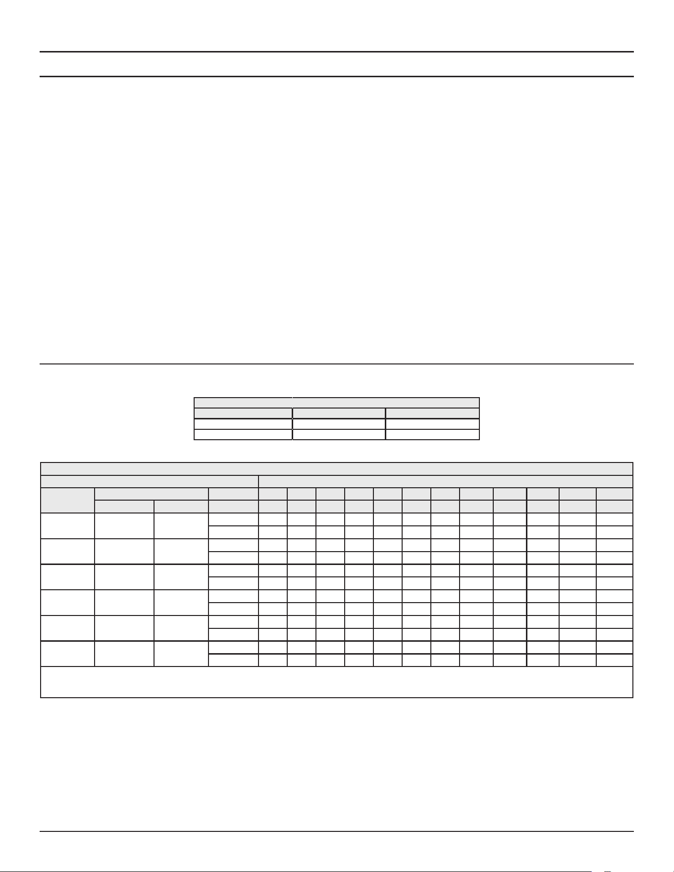
CAPACITIES AND PERFORMANCE
Table 1. Storage Capacities
Model U. S. Gallons Liters
220G 220 833
250G 250 946
Table 2. Recovery Capacities
U. S. Gallons/hr & liters/hr at temperature rise indicated
Model
(kbtu/h)
Input °F 30°F 40° F 50°F 60°F 70°F 80°F 90°F 100°F 110°F 120°F 130°F 140°F
Btu/hr kWh °C 17°C 22°C 28°C 33°C 39°C 44°C 50°C 56°C 61°C 67°C 72°C 78°C
150 150,000 44
GPH 582 436 349 291 249 218 194 175 159 145 134 125
LPH 2202 1652 1321 1102 944 826 734 661 601 551 508 472
199.9 199,900 58
GPH 767 575 460 384 329 288 256 230 209 192 177 164
LPH 2904 2178 1743 1452 1245 1089 968 871 792 726 670 622
250 250,000 73
GPH 949 712 570 475 407 356 316 285 259 237 219 203
LPH 3594 2695 2156 1797 1540 1348 1198 1078 980 898 829 770
300 300,000 88
GPH 1139 855 684 570 488 427 380 342 311 285 263 244
LPH 4313 3234 2588 2156 1848 1617 1438 1294 1176 1078 995 924
399.9 399,900 117
GPH 1503 1127 902 751 644 563 501 451 410 376 347 322
LPH 5688 4266 3413 2844 2438 2133 1896 1706 1551 1422 1313 1219
499.9 499,900 146
GPH 1858 1394 1115 929 796 697 619 557 507 465 429 398
LPH 7033 5275 4220 3517 3014 2638 2344 2110 1918 1758 1623 1507
Recovery capacities are based on 95% thermal efficiency.
High-Eciency Commercial Gas Water Heaters • 15
INSTALLATION CONSIDERATIONS
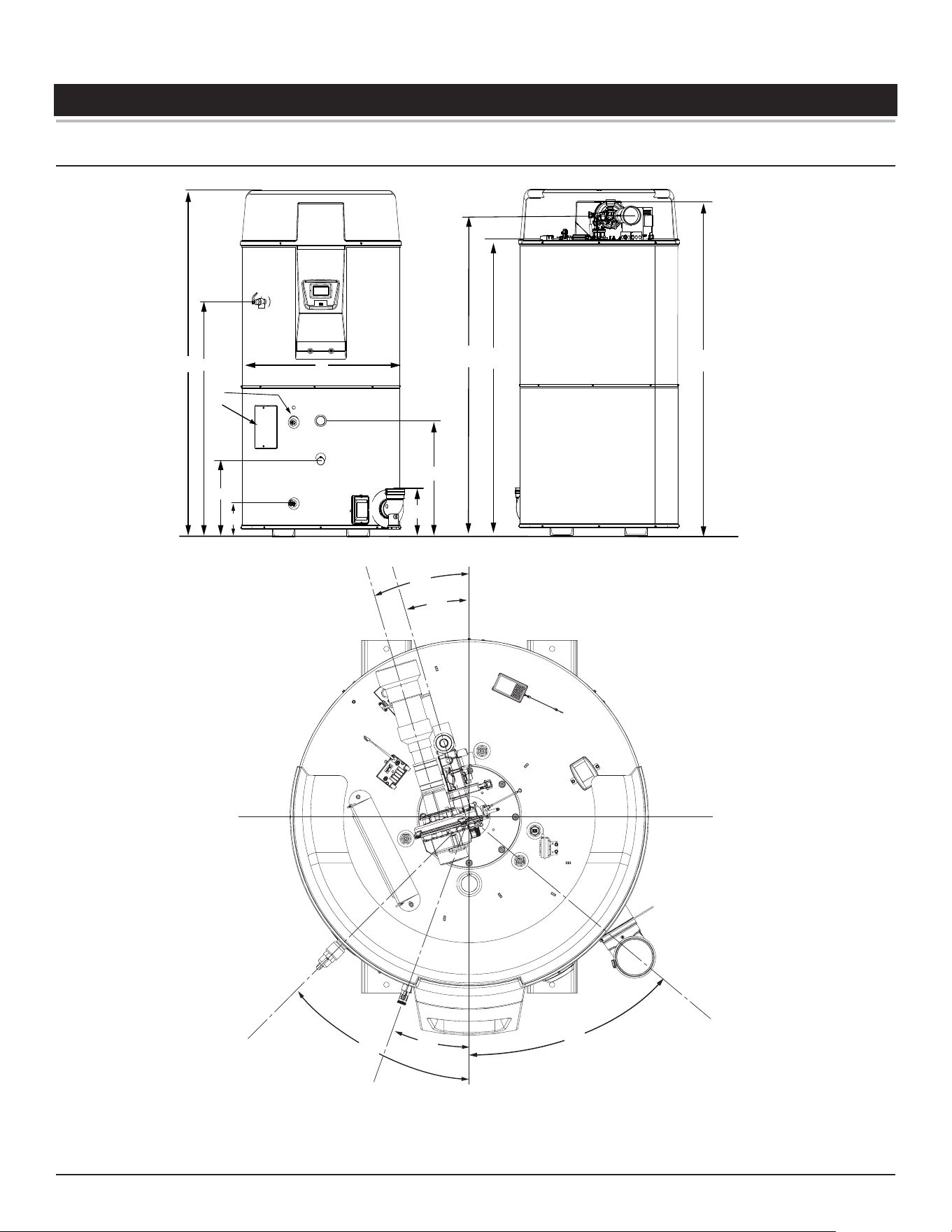
ROUGH-IN DIMENSIONS
FRONT
BACK
A
T & P VALVE
B
G
C
D
E
J
INTAKE AIR
CONNECTION
H
SUPPLY GAS
CONNECTION
I
WATER OUTLET
HEIGHT
F
VENT
CONNECTION
CLEANOUT
3/4” NPT
DRAIN
3/4” NPT
RECIRCULATION
RETURN
1 1/2” NPT
WATER
INLET
LOWER
TEMPERATURE
PROBE
Intake Air
Gas Line
T&P Valve/Clean-out Door
Drain Valve
Exhaust
47
°
47
°
20
°
18
°
15
°
Figure 7. Rough-In Dimensions (220 Gallon Models)
16 • High-Eciency Commercial Gas Water Heaters
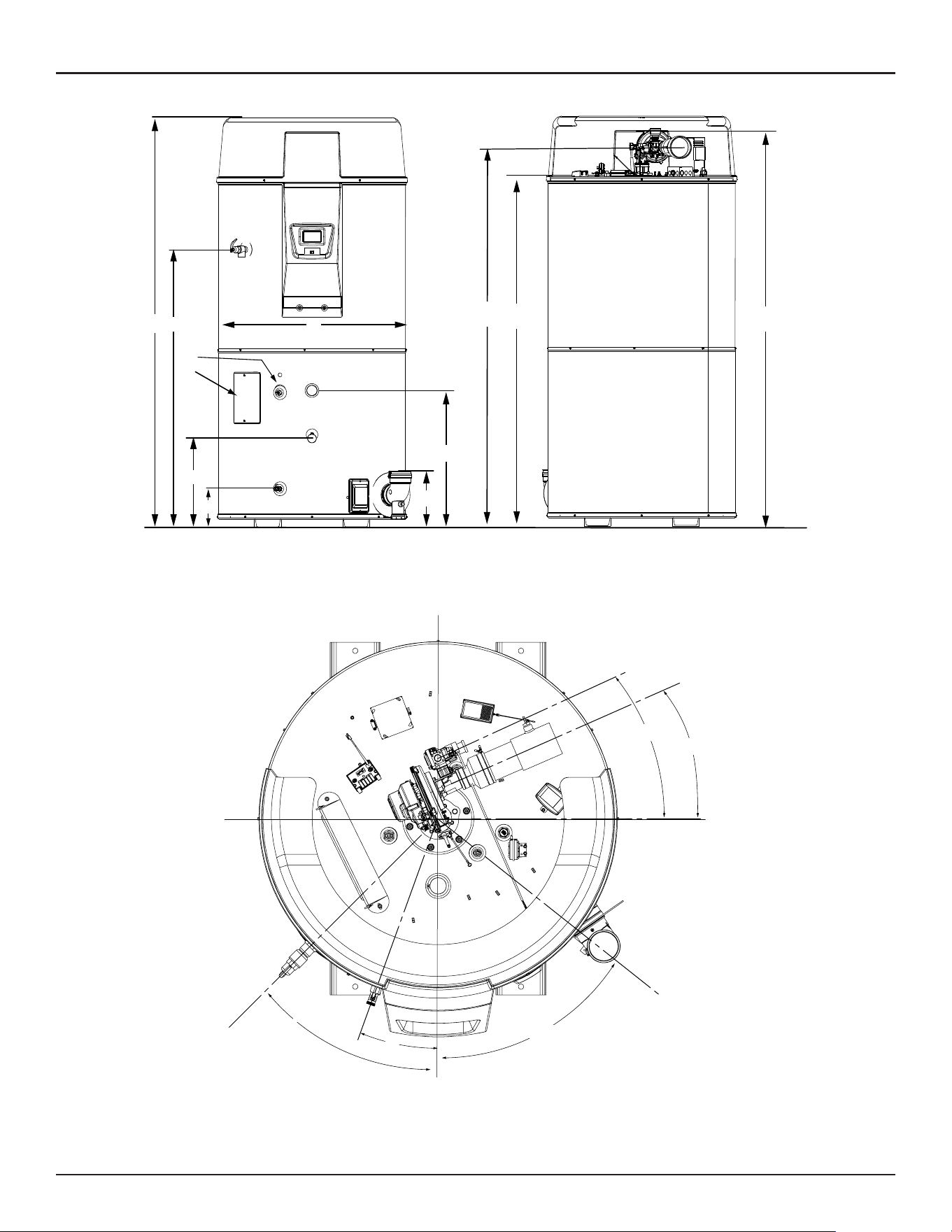
Installation Considerations
FRONT
BACK
A
T & P VALVE
B
G
C
D
E
J
INTAKE AIR
CONNECTION
H
SUPPLY GAS
CONNECTION
I
WATER OUTLET
HEIGHT
F
VENT
CONNECTION
CLEANOUT
3/4” NPT
DRAIN
3/4” NPT
RECIRCULATION
RETURN
1 1/2” NPT
WATER
INLET
LOWER
TEMPERATURE
PROBE
23
°
22
°
51
°
45
°
20
°
T&P Valve/Clean-out Door
Drain Valve
Exhaust
Intake Air
Gas Line
Figure 8. Rough-In (250 Gallon Models)
Installation Considerations
High-Eciency Commercial Gas Water Heaters • 17
Table 3. Dimensions by Model
Model
A B C D E F G H I J
APPROX.
HEATER
WEIGHT
APPROX.SHIP
WEIGHT
Inches
(cm) Inches (cm) Inches (cm)
Inches
(cm) Inches (cm)
Inches
(cm)
Inches
(cm) Inches (cm)
Inches
(cm)
Inches
(cm)
LBS
(KG)
LBS
(KG)
220G
91-1/2
(232.4)
62-5/8
(159)
41-13/16
(107)
20-3/4
(52.71)
8-1/2
(21.59)
78-1/8
(198.45)
12
(30.48)
84 (213.4)
89-3/4
(227.97)
30-1/2
(77.47)
925
(419.5)
1125 (508)
250G
91-1/2
(232.4)
62-5/8
(159)
41-13/16
(107)
20-1/2 (52)
8-1/2
(21.59)
78-1/8
(198.45)
12
(30.48)
85 (215.9)
90-1/8
(228.93)
30-1/2
(77.47)
925
(419.5)
1125 (508)
Table 4. Fuel Type/Connection Size by Model
Model † Input Rate kbtu/h Series Natural Gas Propane Gas
220G 300-499 400-401 to 400-401-450-45 1 1/2" NPT 1 1/2" NPT
250G 150-250 400-401 to 400-401-450-45 3/4" NPT 3/4" NPT
† Depending on the installed equivalent length, and/or the number of appliances
connected, the supply gas line size may have to be increased beyond the minimum
required sizes. See
Gas Line Sizing
(page 51).
Table 5. Gas Pressure Requirements
Model
*Manifold Pressure Minimum Supply Pressure Maximum Supply Pressure
Natural Gas Propane Gas Natural Gas Propane Gas Natural Gas Propane Gas
220G 0" W.C. (0 kPa) 0" W.C. (0 kPa) 3.5” W. C. (1.10 kPa) 8.0” W. C. (2.12 kPa) 14” W. C. (3.49 kPa) 14” W. C. (3.49 kPa)
250G 0” W. C. (0 kPa) 0” W. C. (0 kPa) 3.5” W. C. (1.10 kPa) 8.0” W. C. (2.12 kPa) 14” W. C. (3.49 kPa) 14” W. C. (3.49 kPa)
* The manifold pressure is the factory setting and is not adjustable. A negative pressure will be seen with just the blower running without the
Gas Control Valve open.
LOCATING THE WATER HEATER
Carefully choose a location for the new water heater. The placement is a
very important consideration for the safety of the occupants in the building
and for the most economical use of the water heater.
CAUTION
Property Damage Hazard
Over me, the tank and fings of the water heater
can begin to leak and cause water damage.
• Locate the water heater near an adequate drain
and in an area where water leakage from the
heater or connecons will not result in damage to
the area or the lower floors of the structure.
• Install the water heater in a drain pan.
Whether replacing an existing water heater or installing the water heater
in a new location observe the following critical points:
1. The water heater must be located indoors.
2. The water heater must not be located in an area where it will be subject
to freezing temperatures.
3. Locate the water heater so it is protected and not subject to physical
damage by a moving vehicle.
4. Locate the water heater on a level surface.
5. Locate the water heater near a floor drain. The water heater should be
located in an area where leakage of the tank or connections will not
result in damage to the area adjacent to the water heater or to lower
floors of the structure. When such locations cannot be avoided, it is
recommended that a metal drain pan, adequately drained, be installed
under the water heater.
6. Locate the water heater close to the point of major hot water usage.
7. Locate the water heater close to a 120 VAC power supply. See
Power
Supply
(page 20) for requirements.
8. Locate the water heater where an adequate supply of fresh air for
combustion and ventilation can be obtained. See
Air Requirements
(page 24).
9. Locate the water heater where the vent and intake air piping, when
installed, will remain within the maximum equivalent lengths allowed.
See
Venting Requirements
(page 32).
10. Do not locate the water heater where noise (such as the Combustion
Blower) during normal operation will be objectionable in adjacent areas.
11. Do not locate the water heater where the subsequent installation of
the vent (exhaust) or intake air terminations would be objectionable
due to noise at the termination(s). This includes locations close to or
across from windows and doors. See
Venting Installation
(page 29).
There is a risk in using fuel burning appliances such as gas water heaters
in rooms, garages or other areas where gasoline, other flammable liquids
or engine driven equipment or vehicles are stored, operated or repaired.
Flammable vapors are heavy and travel along the floor and may be
ignited by the water heater’s igniter or Main Burner flames causing fire
or explosion.
Flammable items, pressurized containers or any other potential fire
hazardous articles must never be placed on or adjacent to the water heater.
• Do not store or use gasoline or other flammable
vapors and liquids in the vicinity of this or any other
appliance.
• Avoid all ignition sources if you smell gas.
• Do not expose water heater controls to excessive gas
pressure.
• Use only the gas shown on the water heater rating
label.
• Maintain required clearances to combustibles.
• Keep ignition sources away from faucets after
extended periods of non-use.
Read instruc�on manual before installing, using or
servicing water heater.
⚠
WARNING
Fire or Explosion Hazard
18 • High-Eciency Commercial Gas Water Heaters
Installation Considerations
Clearance To Combustible Materials
The water heaters covered in this manual are approved for installation on
combustible flooring. The clearance to combustible and non combustible
construction materials is zero inches on the back and sides of the water
heater. These water heaters are also approved for installation in an alcove.
FLAMMABLES
Vapors from flammable
liquids may explode
and catch fire causing
death or sever burns.
Water heater has a main
burner and ignition device.
The ignition device:
1. Can come on at any time.
2. Will ignite flammable
vapors.
Do not use or store flammable
products, such as gasoline,
solvents, or adhesives in the
same room or area near the
water heater.
Keep flammable products:
1. Far away from heater.
2. In approved containers.
3. Tightly closed and
4. Out of children’s reach
Vapors:
1. Cannot be seen.
2. Are Heavier than air.
3. Go a long way on the floor.
4. Can be carried from other
rooms to the ignition
device by air currents.
Installation:
Do not install the water heater where flammable
products will be stored or used unless the main burner
and igniter are at least 18" (457 cm) above the floor.
This will reduce, but not eliminate the risk of vapors
being ignited by the main burner or hot surface igniter.
⚠
DANGER
Fire or Explosion Hazard
Flammable Vapors
When the water heater is installed directly on carpeting, the water heater
shall be installed on a metal or wood panel extending beyond the full width
and depth of the water heater by at least three inches (76.2 mm) in any
direction or, if the water heater is installed in an alcove or closet, the entire
floor shall be covered by the panel. The panel must be strong enough to
carry the weight of the heater when full of water.
Read the instruc�on manual before installing,
using, or servicing the water heater.
• Improper use can result in fire or explosion.
• Maintain required clearances to combustibles.
⚠
WARNING
Fire and Explosion Hazard
Note: Adequate clearance for servicing should be maintained on all
installations. See
Service Clearance
(page 18).
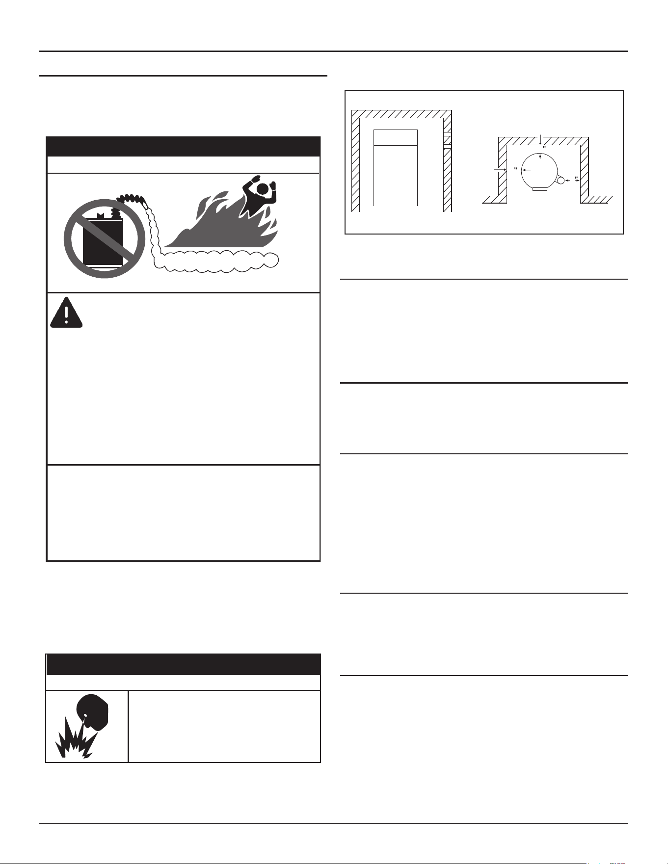
TOP VIEW
0
0
0
ALCOVE
FRONT VIEW
CLEARANCES TO COMBUSTIBLE
AND NON COMBUSTIBLE
CONSTRUCTION MATERIALS
WATER
HEATER
FRONT
TOP COVER
FRONT
Figure 9. Clearances
Service Clearance
A service clearance of 24 inches (61 cm) should be maintained from
serviceable parts such as the T&P valve, control system components,
gas valve, clean out opening, drain valve, the vent connection (exhaust/
condensate elbow). Leave as much room as possible above the water
heater and near the exhaust elbow for this reason. See
Figure 11
(page
23).
Intake Air and Vent Pipe Clearances
The minimum clearance from combustible materials for the vent (exhaust)
and intake air piping shall be 0 inches. Vent or intake air piping passing
through a combustible wall or ceiling must be a continuous run (no joints).
OPTIONAL TERMINATIONS
The water heaters covered in this manual can be installed in a
direct
vent
configuration using optional concentric or low-profile terminations.
See
Concentric Termination Installation
(page 41) and
Low-Profile Vent
Termination installation
(page 44).
Concentric and low profile terminations must be ordered separately.
Contact your local distributor or Technical Support for assistance in ordering
the concentric termination or low-profile vent termination. See the contact
information label on the water heater.
HARD WATER
Where hard water conditions exist, water softening or the threshold type of
water treatment is recommended. This will protect the dishwashers, coffee
urns, water heaters, water piping and other equipment. See
Maintenance
(page 77) for sediment and lime scale removal procedures.
CIRCULATION PUMPS
A circulating pump is used when a system requires a circulating loop or
there is a storage tank used in conjunction with the water heater. The
tank is provided with a 3/4" NPT recirculation loop return connection. See
Piping Diagrams
(page 102) for installation location of circulating pumps.
See
Circulation Pump Wiring Diagrams
(page 100) for electrical hookup
information. Install in accordance with the current edition of the
National
Electrical Code
,
NFPA 70
or the
Canadian Electrical Code
,
CSA C22.1
.
Stainless steel circulating pumps are recommended for use with
commercial water heaters.
Installation Considerations
High-Eciency Commercial Gas Water Heaters • 19
Refer to the circulating pump manufacturer’s instructions for its operation,
lubrication, and maintenance instructions.
INSULATION BLANKETS
• Do not obstruct water heater air intake
with insula�ng blanket.
• Gas and carbon monoxide detectors are
available.
• Install water heater in accordance with the
instruc�on manual.
Breathing carbon monoxide can cause brain damage or death. Always read
and understand instruc�on manual.
⚠
WARNING
Breathing Hazard - Carbon Monoxide Gas
Insulation blankets are available to the general public for external use on
gas water heaters but are not necessary with these products. The purpose
of an insulation blanket is to reduce the standby heat loss encountered
with storage tank heaters. The water heaters covered by this manual meet
or exceed the
Energy Policy Act
standards with respect to insulation and
standby heat loss requirements, making an insulation blanket unnecessary.
If you choose to apply an insulation blanket to this heater, you should follow
these instructions. See
Features and Components
(page 10) section of
this manual for identification of components mentioned below. Failure
to follow these instructions can restrict the air flow required for proper
combustion, potentially resulting in fire, asphyxiation, serious personal
injury or death.
•
Do not
apply insulation to the top of the water heater, as this will
interfere with safe operation of the blower assembly.
•
Do not
cover the control system LCD on top of the water heater.
•
Do not
cover the Temperature-Pressure Relief Valve.
•
Do not
cover the instruction manual. Keep it on the side of the water
heater or nearby for future reference.
•
Do
obtain new warning and instruction labels from the manufacturer
for placement on the blanket directly over the existing labels.
•
Do
inspect the insulation blanket frequently to make certain it does
not sag, thereby obstructing combustion air flow.

20 • High-Eciency Commercial Gas Water Heaters
INSTALLATION REQUIREMENTS
GAS SUPPLY SYSTEMS
Low pressure building gas supply systems are defined as those systems that
cannot under any circumstances exceed 14” W.C. (1/2 PSI Gauge). These
systems do not require pressure regulation. Measurements should be taken
to insure that gas pressures are stable and fall within the requirements
stated on the water heater rating plate. Readings should be taken with
all gas burning equipment off (static pressure) and with all gas burning
equipment running at maximum rate (dynamic pressure). The gas supply
pressure must be stable within 1.5” W.C. from static to dynamic pressure
to provide good performance. Pressure drops that exceed 1.5” W.C. may
cause rough starting, noisy combustion or nuisance outages. Increases or
spikes in static pressure during off cycles may cause failure to ignite or in
severe cases damage to appliance gas valves. If your low pressure system
does
NOT
meet these requirements, the installer is responsible for the
corrections.
High Pressure building supply systems use pressures that exceed 14”
W.C. (1/2 PSI Gauge). These systems must use field-supplied regulators
to lower the gas pressure to less than 14” W.C. (1/2 PSI Gauge). Water
heaters require gas regulators that are properly sized for the water heater
input and deliver the rating plate specified pressures. Gas supply systems
where pressure exceeds 5 PSI often require multiple regulators to achieve
desired pressures. Systems in excess of 5 PSI building pressure should be
designed by gas delivery professionals for best performance. Water heaters
connected to gas supply systems that exceed 14” W.C. (1/2 PSI Gauge) at
any time must be equipped with a gas supply regulator.
The water heaters covered in this manual require a minimum gas supply
pressure of 3.5" W.C. for natural gas and 8.0" W.C. for propane gas. The
minimum supply pressure is measured while gas is flowing (dynamic
pressure). The supply pressure should never fall below 3.5" W.C. for natural
gas and 8.0" W.C. for propane gas. The supply pressure should be measured
with all gas fired appliances connected to the common main firing at full
capacity. If the supply pressure drops more than 1.5” W.C. as gas begins
to flow to the water heater then the supply gas system including the gas
line and/or the gas regulator may be restricted or undersized. See
Supply
Gas Regulator
section of this manual. The gas valve on all models has a
maximum gas supply pressure limit of 14” W.C. The maximum supply
pressure is measured while gas is not flowing (static pressure).
SUPPLY GAS REGULATOR
The maximum allowable gas supply pressure for this water heater is 14.0
inches W.C. (3.49 kPa) for natural and propane gas. Install a positive lock-
up gas pressure regulator in the gas supply line if inlet gas pressure can
exceed these pressures at any time.
If a positive lock-up regulator is required follow these instructions:
1. Positive lock-up gas pressure regulators must be rated at or above the
input Btu/hr rating of the water heater they supply.
2. Supply gas regulators shall have inlet and outlet connections not less
than the minimum supply gas line size for the water heater they supply.
See
Table 16
(page 51).
3. Positive lock-up gas pressure regulator(s) should be installed no closer
than 3 feet (1 meter) and no farther than 8 feet (2.4 meters) from the
water heater’s inlet gas connection.
4. After installing the positive lock-up gas pressure regulator(s) an initial
nominal supply pressure setting of 7.0” W.C. while the water heater
is operating is recommended and will generally provide good water
heater operation. Some additional adjustments may be required later
to maintain a steady gas supply pressure.
5. When installing multiple water heaters in the same gas supply system it
is recommended that individual positive lock-up gas pressure regulators
be installed at each unit from the supply gas connection on the water
heater.
Ensure that the gas line is properly supported to prevent damage to the
gas train.
POWER SUPPLY
The water heaters covered in this manual require a 120 VAC, 1Ø (single
phase), 60 Hz, 15 amp power supply and must also be electrically grounded
in accordance with local codes or, in the absence of local codes, with the
National Electrical Code
,
ANSI/NFPA 70
or the
Canadian Electrical Code,
CSA C22.1
.
Dedicated Power Wiring and Breakers
Dedicated power supply wires, neutral wires, ground wiring, and dedicated
circuit breakers, often prevent electrical line noise and are required when
installing the water heater.
Note: This water heater should not be connected to an electrical supply
with a Ground Fault Circuit Interrupter (GFCI) or Arc Fault Circuit
Interrupter (AFCI) with Integral GFCI protection as defined in
NFPA
70
,
CSA C22.1
and
UL 943
.
Power Fluctuations and Electrical Noise
The water heater’s control system requires a source of stable clean
electricity for proper operation. Connecting the water heater to a branch
circuit that is subject to fluctuations in voltage level or electrical line
noise such as EMI (electromagnetic interference) or RFI (radio frequency
interference) may cause erratic control system operation and malfunction.
A high quality power supply filter/suppressor must be installed if the
above conditions exist. Contact a local power filter/suppressor supplier
for more information.
Note: Malfunctions caused by the power supply and costs to install
power supply filters are not covered under the limited warranty.
See Commercial Water Heater Limited Warranty.
Installation Requirements
High-Eciency Commercial Gas Water Heaters • 21
MIXING VALVES
Water heated to a temperature which will satisfy clothes washing, dish
washing, and other sanitizing needs can scald and cause permanent injury
upon contact. Short repeated heating cycles caused by small hot water uses
can cause temperatures at the point of use to exceed the water heater’s
temperature setting by up to 20°F (11°C).
Water temperature over 52°C (125°F) can cause severe
burns instantly resul�ng in severe injury or death.
Children, the elderly and the physically or mentally
disabled are at highest risk for scald injury.
Feel water before bathing or showering.
Temperature limi�ng devices such as thermosta�c
point-of-use mixing valves must be installed when
required by codes and to ensure safe temperatures at
fixtures.
⚠
DANGER
Burn Hazard
Some people are more likely to be permanently injured by hot water than
others. These include the elderly, children, the infirm and the physically/
mentally disabled.
Table 6
shows the approximate time-to-burn relationship
for normal adult skin. If anyone using hot water provided by the water
heater being installed fits into one of these groups or if there is a local
code or state law requiring a certain water temperature at the point of
use, then special precautions must be taken.
In addition to using the lowest possible temperature setting that satisfies
your hot water needs, a means such as a mixing valve , for example, can be
used at the water heater or at the hot water taps used by these people to
reduce the water temperature.
See
Figure 10
.
Check State and/or local codes for mixing valve requirements and
installation practices.
Mixing valves are available at plumbing supply stores. Consult a Qualified
Installer or Service Agency. Follow mixing valve manufacturer’s instructions
for installation of the valves.
Table 6. Burn Time at Various Temperatures
Water Temperature
°F (°C)
Time for 1st Degree Burn
(Less Severe Burns)
Time for Permanent Burns
2nd & 3rd Degree
(Most Severe Burns)
110 (43) (normal shower temp.)
116 (47) (pain threshold)
116 (47) 35 minutes 45 minutes
122 (50) 1 minute 5 minutes
131 (55) 5 seconds 25 seconds
140 (60) 2 seconds 5 seconds
149 (65) 1 second 2 seconds
154 (68) instantaneous 1 second
(U.S. Government Memorandum, C.P.S.C., Peter L. Armstrong, Sept. 15, 1978)
DISH-WASHING MACHINES
All dish-washing machines meeting the National Sanitation Foundation
requirements are designed to operate with water flow pressures between
15 and 25 pounds per square inch (103 kPa and 173 kPa). Flow pressures
above 25 pounds per square inch (173 kPa), or below 15 pounds per square
inch (103 kPa), will result in improperly sanitized dishes. Where pressures
are high, a water pressure reducing or flow regulating control valve should
be used in the 180°F (82°C) line to the dish-washing machine and should
be adjusted to deliver water pressure between these limits.
HOT WATER
OUTLET
TO TANK
INLET
CHECK
VALVE
MIXING
VALVE
COLD
WATER
INLET
TEMPERED WATER
OUTLET
12” TO 15”
(30-38 cm)
CHECK
VALVE
Figure 10. Mixing Valve
The
National Sanitation Foundation
also recommends circulation of 180°F
(82°C) water. The circulation should be just enough to provide 180°F (82°C)
water at the point of take-off to the dish-washing machine.
Adjust flow by throttling a full port ball valve installed in the circulating line
on the outlet side of the pump. Never throttle flow on the suction side of
a pump. See
Piping Diagrams
(page 102).
Note: To comply with
NSF Standard 5
installation requirements, the
bottom of the water heater must be sealed to the floor with a
silicone based sealant or elevated 6 inches above the floor.
CLOSED WATER SYSTEMS
Water supply systems may, because of code requirements or such
conditions as high line pressure, among others, have installed devices
such as pressure reducing valves, check valves, and back flow preventers.
Devices such as these cause the water system to be a closed system.
22 • High-Eciency Commercial Gas Water Heaters
Installation Requirements
THERMAL EXPANSION
As water is heated, it expands (thermal expansion). In a closed system
the volume of water will grow when it is heated. As the volume of water
grows there will be a corresponding increase in water pressure due to
thermal expansion. Thermal expansion can cause premature tank failure
(leakage). This type of failure is not covered under the limited warranty.
Thermal expansion can also cause intermittent Temperature-Pressure
Relief Valve operation: water discharged from the valve due to excessive
pressure build up. This condition is not covered under the limited warranty.
See Commercial Water Heater Limited Warranty Insert.
The Temperature-Pressure Relief Valve is not intended for the constant
relief of thermal expansion.
A properly sized and pressurized thermal expansion tank must be installed
on all closed systems to control the harmful effects of thermal expansion.
Contact a local plumbing service agency to have a thermal expansion tank
installed.
See
Water Line Connections
(page 53) and the
Piping Diagrams
(page
102).
TEMPERATURE-PRESSURE RELIEF VALVE
This water heater is provided with a properly rated/sized and certified
combination Temperature-Pressure Relief Valve (T&P valve) by the
manufacturer. The valve is certified by a nationally recognized testing
laboratory that maintains periodic inspection of production of listed
equipment of materials as meeting the requirements for Relief Valves
for Hot Water Supply Systems,
ANSI Z21.22
•
CSA 4.4
, and the code
requirements of
ASME
.
If replaced, the new T&P valve must meet the requirements of local codes,
but not less than a combination Temperature-Pressure Relief Valve rated/
sized and certified as indicated in the above paragraph. The new valve
must be marked with a maximum set pressure not to exceed the marked
hydrostatic working pressure of the water heater (150 psi = 1,035 kPa) and
a discharge capacity not less than the water heater Btu/hr or kW input
rate as shown on the water heater’s model rating label.
Normal opera�on of the water heater can cause
it to become sufficiently over-heated and/or
over-pressurized that it can explode, resul�ng in
property damage, sever injury, or death.
To avoid this hazard, you must install a properly-
sized temperature-pressure relief valve in opening
provided.
• The temperature-pressure relief valve must
comply with ANSI Z21.22-CSA 4.4 and ASME
code.
• Do not plug, block, or cap the discharge line.
⚠
WARNING
Explosion Hazard
Note: In addition to the factory-installed Temperature-Pressure Relief
Valve on the water heater, each remote storage tank that may be
installed and piped to a water heating appliance must also have
its own properly sized, rated and approved Temperature-Pressure
Relief Valve installed. Contact your local distributor or contact
Technical Support for assistance in sizing a Temperature-Pressure
Relief Valve for remote storage tanks. See the contact information
label on the water heater.
For safe operation of the water heater, the Temperature-Pressure Relief
Valve must not be removed from its designated opening nor plugged. The
Temperature-Pressure Relief Valve must be installed directly into the fitting
of the water heater designed for the relief valve. Install discharge piping so
that any discharge will exit the pipe six inches (15.2 cm) above an adequate
floor drain, or external to the building. In cold climates it is recommended
that it be terminated at an adequate drain inside the building. Be certain
that no contact is made with any live electrical part. The discharge opening
must not be blocked or reduced in size under any circumstances. Excessive
length, over 30 feet (9.14 m), or use of more than four elbows can cause
restriction and reduce the discharge capacity of the valve.
No valve or other obstruction is to be placed between the Temperature-
Pressure Relief Valve and the tank. Do not connect discharge piping directly
to the drain. A six inch (15.2 cm) air gap must be provided. To prevent bodily
injury, hazard to life, or property damage, the relief valve must be allowed
to discharge water in adequate quantities if circumstances demand. If the
discharge pipe is not connected to a drain or other suitable means, the
water flow may cause property damage.
Property Damage Hazard
While the water heater is in rou�ne opera�on, it can
release hot water from the temperature-pressure relief
valve discharge pipe in quan��es that could cause
damage to the surroundings.
Locate the water heater near an adequate drain and
in an area where water from the temperature-pres-
sure relief valve discharge pipe will not result in
damage to the area or the lower floors of the
structure.
⚠
CAUTION
T&P Valve Discharge Pipe Requirements
• Shall not be smaller in size than the outlet pipe size of the valve, or
have any reducing couplings or other restrictions.
• Shall not be plugged or blocked.
• Shall not be exposed to freezing temperatures.
• Shall be of material listed for hot water distribution.
• Shall be installed so as to allow complete drainage of both the
Temperature-Pressure Relief Valve and the discharge pipe.
• Must terminate six inches (15.2 cm) above a floor drain or external
to the building. In cold climates, it is recommended that the
discharge pipe be terminated at an adequate drain inside the
building.
• Shall not have any valve or other obstruction between the relief
valve and the drain.
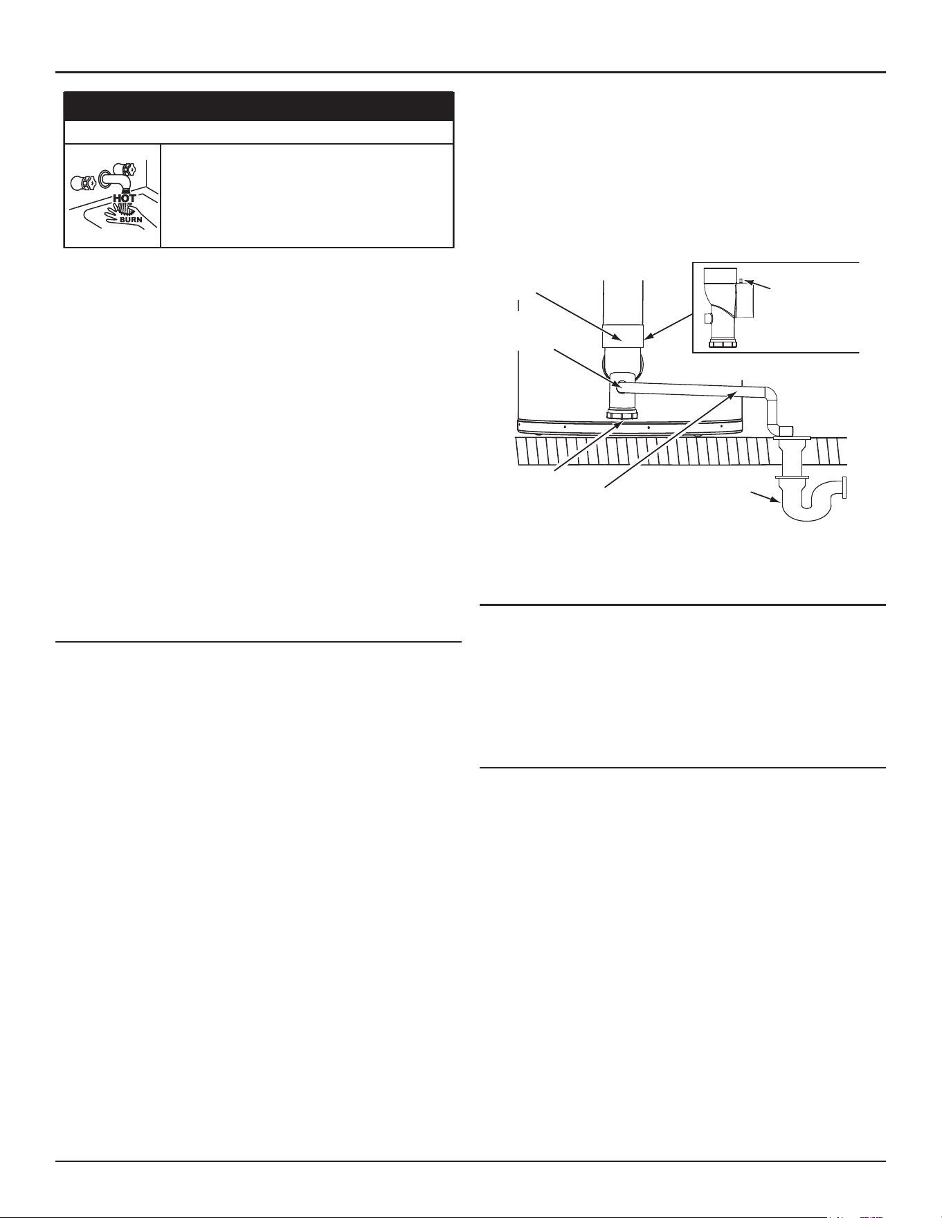
Installation Requirements
High-Eciency Commercial Gas Water Heaters • 23
⚠
DANGER
Burn Hazard
The discharge water from the temperature-pressure
relief valve is hot enough to cause burns.
Keep clear of the temperature-pressure relief valve
discharge outlet.
The Temperature-Pressure Relief Valve must be manually operated at
least twice a year. Caution should be taken to ensure that (1) no one is
in front of or around the outlet of the Temperature-Pressure Relief Valve
discharge line, and (2) the water manually discharged will not cause any
bodily injury or property damage because the water may be extremely
hot. If after manually operating the valve, it fails to completely reset and
continues to release water, immediately close the cold water inlet to the
water heater, follow the draining instructions in this manual, and replace
the Temperature-Pressure Relief Valve with a properly rated/sized new one.
Note: The purpose of a Temperature-Pressure Relief Valve is to prevent
excessive temperatures and pressures in the storage tank. The T&P
valve is not intended for the constant relief of thermal expansion.
A properly sized thermal expansion tank must be installed on all
closed systems to control thermal expansion, see
Thermal Expansion
(page 22)
and
Closed Water Systems
(page 21).
If you do not understand these instructions or have any questions regarding
the Temperature-Pressure Relief Valve Contact your local distributor or
contact Technical Support for assistance. See the contact information
label on the water heater.
CONDENSATE DRAIN
The water heaters covered in this manual are condensing appliances
and require a building drain to be located in close proximity to allow the
condensate to drain safely.
Condensate drains from the water heater at the exhaust elbow located at
the bottom. The field installed condensate drain line must not be elevated
above the condensate drain connection on the built-in condensate trap, see
Figure 11
. If the condensate does not drain properly it will build up in the
exhaust (vent) elbow. This will restrict the flow of flue gases and cause the
Blocked Exhaust Pressure switch to open its contacts. The control system
monitors all pressure switches. If the Blocked Exhaust switch contacts are
open, the control system will lock out and disable heating operation. The
“Blocked Exhaust Fault" message will be displayed on the control system’s
LCD. See
Fault and Alert Messages
(page 86).
The Condensate Clean-out Cap must be on and tight when unit is in
operation.
The exhaust elbow has a built-in condensate trap. Do not install an
additional trap in the condensate drain piping, see
Figure 11
.
Note: If the “Blocked Exhaust Fault" message is displayed on the control
system LCD, check the condensate drain first and ensure it is not
blocked. Periodically, inspect and clean the built-in condensate
trap of any debris.
EXHAUST (VENT)
ELBOW
THIS SIDE VIEW
OF EXHAUST
ELBOW AND
ARROW INDICATE
THE LOCATION OF
THE PRESSURE
PORT
BUILDING
DRAIN
CONDENSATE
CLEANOUT CAP
CONDENSATE DRAIN
LINE - FIELD INSTALLED
CONDENSATE
DRAIN LINE
CONNECTION
Figure 11. Exhaust/Condensate Elbow
Condensate Drain Water Trap
Do not
remove the factory-installed exhaust/condensate elbow (see
Figure 11
) for any reason. The water heater’s vent pipe is under a slight
positive pressure while unit is in operation. The water trap inside of the
exhaust/condensate elbow prevents flue gases from escaping into the
installed space. The exhaust elbow has a built in condensate trap. Do not
install an additional trap in the condensate drain piping. See
Figure 11
and
Condensate Drain Installation
(page 49).
Condensate pH Level
The condensate drains from the water heater’s covered in this manual have
pH levels between 4.3 and 5.0. Install a commercially available neutralizing
kit if required by local codes.
Note: Lower pH levels are acidic. Do not connect a metal drain line, such
as copper, to the water heater for this reason. See
Condensate Drain
Installation
(page 49).
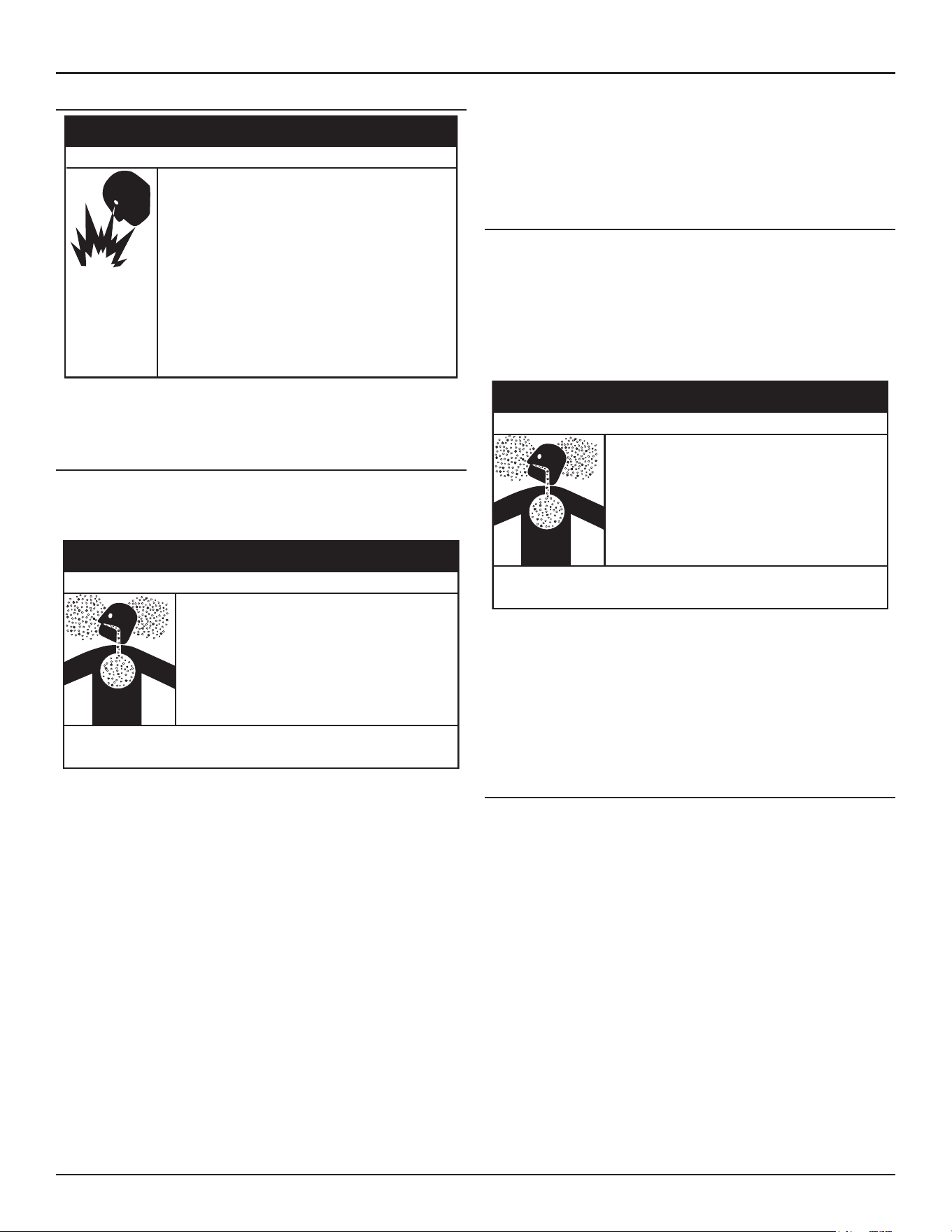
24 • High-Eciency Commercial Gas Water Heaters
Installation Requirements
COMBUSTIBLE MATERIAL STORAGE
• Do not store or use gasoline or other flammable
vapors and liquids in the vicinity of this or any other
appliance.
• Avoid all ignition sources if you smell gas.
• Do not expose water heater controls to excessive gas
pressure.
• Use only the gas shown on the water heater rating
label.
• Maintain required clearances to combustibles.
• Keep ignition sources away from faucets after
extended periods of non-use.
Read instruc�on manual before installing, using or
servicing water heater.
⚠
WARNING
Fire or Explosion Hazard
Keep water heater area clear and free of combustible materials, gasoline,
and other flammable vapors and liquids.
CONTAMINATED AIR
Corrosion of the flue ways and vent system may occur if air for combustion
contains certain chemical vapors. Such corrosion may result in failure and
risk of asphyxiation.
• Install water heater in accordance with
the Instruction Manual and NFPA 54 or
CAN/CSA-B149.1.
• To avoid injury, combustion and ventilation air
must be taken from outdoors.
• Do not place chemical vapor emitting products
near water heater.
Breathing carbon monoxide can cause brain damage or death. Always
read and understand instruc�on manual.
⚠
WARNING
Breathing Hazard - Carbon Monoxide Gas
Combustion air that is contaminated can greatly diminish the life span
of the water heater and water heater components such as igniters and
burners. Propellants of aerosol sprays, beauty shop supplies, water softener
chemicals and chemicals used in dry cleaning processes that are present
in the combustion, ventilation or ambient air can cause such damage.
Do not store products of this sort near the water heater. Air which is
brought in contact with the water heater should not contain any of these
chemicals. If necessary, uncontaminated air should be obtained from
remote or outdoor sources. The limited warranty is voided when failure
of water heater is due to a corrosive atmosphere. See Commercial Water
Heater Limited Warranty Insert for complete terms and conditions.
If the water heater will be used in beauty shops, barber shops, cleaning
establishments, or self-service laundries with dry cleaning equipment,
it is imperative that the water heater(s) be installed in a Direct Vent
configuration so that all air for combustion is derived directly from
the outdoor atmosphere through a sealed intake air pipe. See
Venting
Installation
(page 29).
AIR REQUIREMENTS
For safe operation an adequate supply of fresh uncontaminated air for
combustion and ventilation must be provided.
An insufficient supply of air can cause recirculation of combustion products
resulting in contamination that may be hazardous to life. Such a condition
often will result in a yellow, luminous burner flame, causing sooting of
the combustion chamber, burners and flue tubes and creates a risk of
asphyxiation.
• Install water heater in accordance with
the Instruction Manual and NFPA 54 or
CAN/CSA-B149.1.
• To avoid injury, combustion and ventilation air
must be taken from outdoors.
• Do not place chemical vapor emitting products
near water heater.
Breathing carbon monoxide can cause brain damage or death. Always
read and understand instruc�on manual.
⚠
WARNING
Breathing Hazard - Carbon Monoxide Gas
Do not install the water heater in a confined space unless an adequate
supply of air for combustion and ventilation is brought in to that space
using the methods described in the
Confined Space
section that follows.
Never obstruct the flow of ventilation air. If you have any doubts or
questions at all, call your gas supplier. Failure to provide the proper amount
of combustion air can result in a fire or explosion and cause property
damage, serious bodily injury or death.
Unconfined Space
An Unconfined Space is one whose volume is not less than 50 cubic feet
per 1,000 Btu/hr (4.8 cubic meters per kW) of the total input rating of
all appliances installed in the space. Rooms communicating directly with
the space, in which the appliances are installed, through openings not
furnished with doors, are considered a part of the unconfined space.
Makeup air requirements for the operation of exhaust fans, kitchen
ventilation systems, clothes dryers and fireplaces shall also be considered
in determining the adequacy of a space to provide combustion, ventilation
and dilution air.
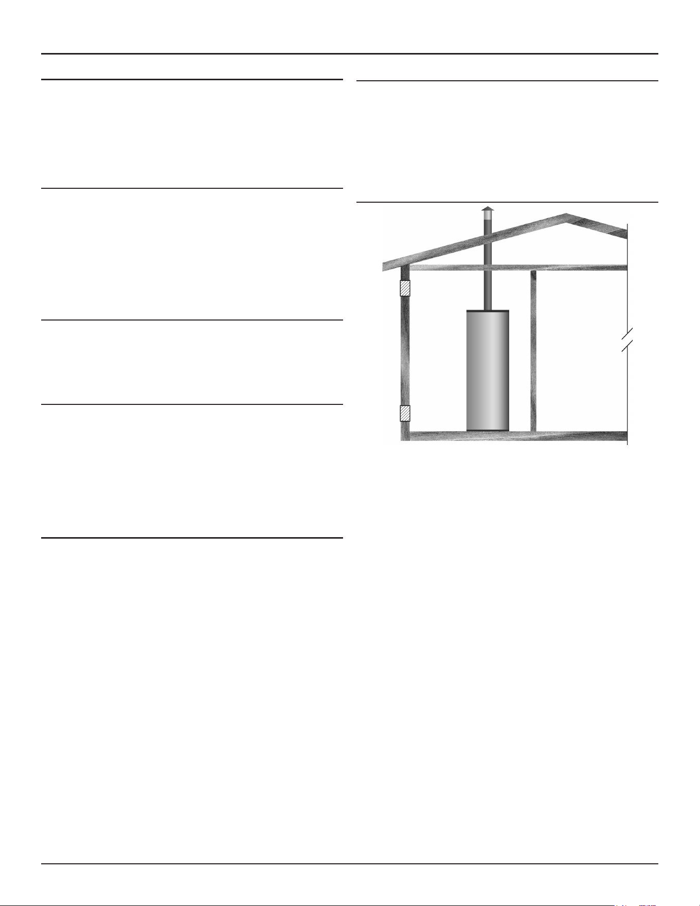
Installation Requirements
High-Eciency Commercial Gas Water Heaters • 25
Unusually Tight Construction
In unconfined spaces in buildings, infiltration may be adequate to provide
air for combustion, ventilation and dilution of flue gases. However, in
buildings of unusually tight construction (for example, weather stripping,
heavily insulated, caulked, vapor barrier, etc.), additional air must be
provided using the methods described in the
Confined Space
section that
follows.
Confined Space
A
confined space
is one whose volume is less than 50 cubic feet per 1,000
Btu/hr (4.8 cm per kW) of the total input rating of all appliances installed
in the space.
Openings must be installed to provide fresh air for combustion, ventilation
and dilution in confined spaces. The required size for the openings is
dependent on the method used to provide fresh air to the confined space
and the total Btu/hr input rating of all appliances installed in the space.
Direct Vent Appliances
Appliances installed in a Direct Vent configuration that derive all air for
combustion from the outdoor atmosphere through sealed intake air piping
are not factored in the total appliance input Btu/hr calculations used to
determine the size of openings providing fresh air into confined spaces.
Exhaust Fans
Where exhaust fans are installed, additional air shall be provided to replace
the exhausted air. When an exhaust fan is installed in the same space with
a water heater, sufficient openings to provide fresh air must be provided
that accommodate the requirements for all appliances in the room and the
exhaust fan. Undersized openings will cause air to be drawn into the room
through the water heater’s vent system causing poor combustion. Sooting,
serious damage to the water heater, and the risk of fire or explosion may
result. It can also create a risk of asphyxiation.
Louvers and Grilles
The free areas of the fresh air openings in the instructions that follow do
not take in to account the presence of louvers, grilles or screens in the
openings.
The required size of openings for combustion, ventilation and dilution air
shall be based on the “net free area” of each opening. Where the free area
through a design of louver or grille or screen is known, it shall be used in
calculating the size of opening required to provide the free area specified.
Where the louver and grille design and free area are not known, it shall
be assumed that wood louvers will have 25% free area and metal louvers
and grilles will have 75% free area. Non motorized louvers and grilles shall
be fixed in the open position.
FRESH AIR OPENINGS FOR CONFINED SPACES
The following instructions shall be used to calculate the size, number and
placement of openings providing fresh air for combustion, ventilation
and dilution in confined spaces. The illustrations shown in this section of
the manual are a reference for the openings that provide fresh air into
confined spaces only.
Do not
refer to these illustrations for the purpose of
vent installation. See
Venting Installation
(page 29) for complete venting
installation instructions.
Outdoor Air Through Two Openings
Figure 12. Outdoor Air Through Two Openings
The confined space shall be provided with two permanent openings, one
commencing within 12 inches (300 mm) of the top and one commencing
within 12 inches (300 mm) of the bottom of the enclosure. The openings
shall communicate directly with the outdoors. See
Figure 12
.
Each opening shall have a minimum free area of 1 square inch per 4,000
Btu/hr (550 mm
2
per kW) of the aggregate input rating of all appliances
installed in the enclosure. Each opening shall not be less than 100 square
inches (645 cm
2
).
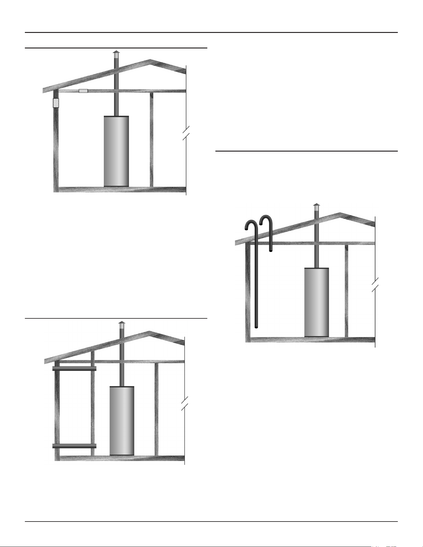
26 • High-Eciency Commercial Gas Water Heaters
Installation Requirements
Outdoor Air Through One Opening
Figure 13. Outdoor Air Through One Opening
Alternatively a single permanent opening, commencing within 12 inches
(300 mm) of the top of the enclosure, shall be provided. See
Figure 13
.
The water heater shall have clearances of at least 1 inch (25 mm) from
the sides and back and 6 inches (150 mm) from the front of the water
heater. The opening shall directly communicate with the outdoors or
shall communicate through a vertical or horizontal duct to the outdoors
or spaces that freely communicate with the outdoors and shall have a
minimum free area of the following:
1. One square inch per 3000 Btu/hr (733 mm
2
per kW) of the total input
rating of all appliances located in the enclosure
2. Not less than the sum of the areas of all vent connectors in the space
Outdoor Air Through Two Horizontal Ducts
Figure 14. Two Horizontal Ducts
The confined space shall be provided with two permanent horizontal
ducts, one commencing within 12 inches (300 mm) of the top and one
commencing within 12 inches (300 mm) of the bottom of the enclosure.
The horizontal ducts shall communicate directly with the outdoors. See
Figure 14
.
Each duct opening shall have a minimum free area of 1 square inch per
2,000 Btu/hr (1100 mm
2
per kW) of the aggregate input rating of all
appliances installed in the enclosure.
When ducts are used, they shall be of the same cross sectional area as the
free area of the openings to which they connect. The minimum dimension
of rectangular air ducts shall be not less than 3 inches.
Outdoor Air Through Two Vertical Ducts
The illustrations shown in this section of the manual are a reference for
the openings that provide fresh air into confined spaces only.
Do not
refer to these illustrations for the purpose of vent installation.
See
Venting Installation
(page 29)
for complete venting installation
instructions.
Figure 15. Two Vertical Ducts
The confined space shall be provided with two permanent vertical
ducts, one commencing within 12 inches (300 mm) of the top and one
commencing within 12 inches (300 mm) of the bottom of the enclosure.
The vertical ducts shall communicate directly with the outdoors. See
Figure 15
.
Each duct opening shall have a minimum free area of 1 square inch
per 4,000 Btu/hr (550 mm
2
per kW) of the aggregate input rating of all
appliances installed in the enclosure.
When ducts are used, they shall be of the same cross sectional area as the
free area of the openings to which they connect. The minimum dimension
of rectangular air ducts shall be not less than 3 inches (7.62 cm).
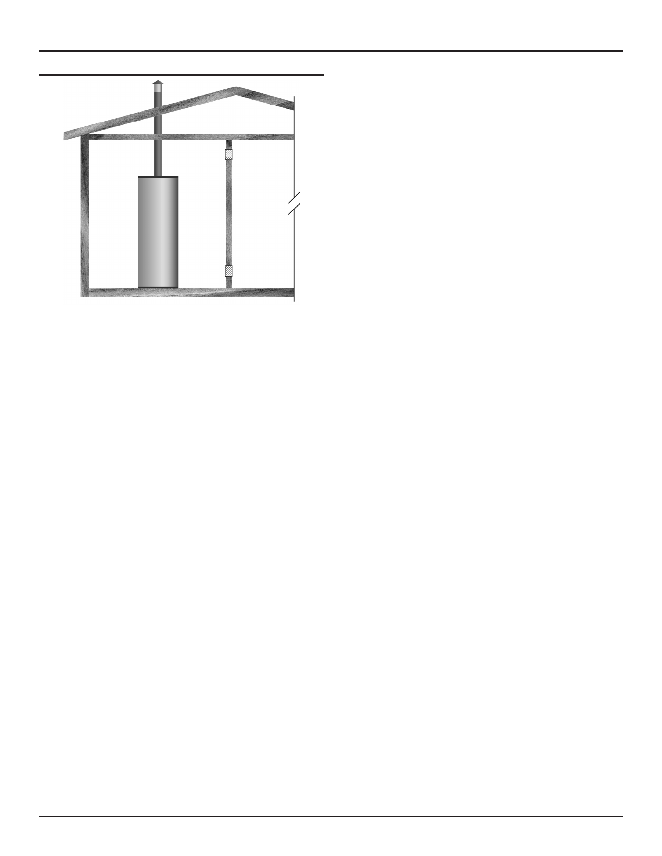
Installation Requirements
High-Eciency Commercial Gas Water Heaters • 27
Air From Other Indoor Spaces
Figure 16. Two Permanent Openings
The confined space shall be provided with two permanent openings, one
commencing within 12 inches (300 mm) of the top and one commencing
within 12 inches (300 mm) of the bottom of the enclosure. See
Figure 16
.
Each opening shall communicate directly with an additional room(s) of
sufficient volume so that the combined volume of all spaces meets the
criteria for an Unconfined Space.
Each opening shall have a minimum free area of 1 square inch per 1,000
Btu/hr (2200 mm
2
per kW) of the aggregate input rating of all appliances
installed in the enclosure. Each opening shall not be less than 100 square
inches (645 cm
2
).

28 • High-Eciency Commercial Gas Water Heaters
Installation Requirements
MASSACHUSETTS REQUIREMENTS
COMMONWEALTH OF MASSACHUSETTS
For all side wall terminated, horizontally vented power vent, direct vent,
and power direct vent gas fueled water heaters installed in every dwelling,
building or structure used in whole or in part for residential purposes,
including those owned or operated by the Commonwealth and where the
side wall exhaust vent termination is less than seven (7) feet above finished
grade in the area of the venting, including but not limited to decks and
porches, the following requirements shall be satisfied:
INSTALLING CARBON MONOXIDE DETECTORS
At the time of installation of the side-wall horizontal-vented gas-fueled
equipment, the installing plumber or gas-fitter shall observe that a hard-
wired carbon-monoxide detector, with an alarm and battery back-up, is
installed on the floor level where the gas equipment is to be installed. In
addition, the installing plumber or gas-fitter shall observe that a battery-
operated or hard-wired carbon-monoxide detector, with an alarm, is
installed on each additional level of the dwelling, building, or structure
served by the side-wall horizontal-vented gas-fueled equipment. It shall
be the responsibility of the property owner to secure the services of
qualified licensed professionals for the installation of hard-wired carbon-
monoxide detectors.
In the event that the side-wall horizontally-vented gas-fueled equipment
is installed in a crawl space or an attic, the hard-wired carbon-monoxide
detector, with alarm and battery back-up, may be installed on the next
adjacent floor level.
In the event that the requirements of this subdivision can not be met at
the time of completion of installation, the owner shall have a period of
thirty (30) days to comply with the above requirements provided that
during said thirty (30) day period, a battery-operated carbon-monoxide
detector, with an alarm, shall be installed.
APPROVED CARBON MONOXIDE DETECTORS
Each carbon-monoxide detector as required in accordance with the above
provisions shall comply with
NFPA 720
and be
ANSI/UL 2034
listed and
CSA
certified.
SIGNAGE
A metal or plastic identification plate shall be permanently mounted to the
exterior of the building at a minimum height of eight (8) feet above grade
directly in line with the exhaust vent terminal for the horizontally-vented
gas-fueled heating appliance or equipment. The sign shall read, in print
size no less than one-half (1/2) inch in size,
“gas vent directly below. Keep
clear of all obstructions.”
INSPECTION
The state or local gas inspector of the side-wall horizontally-vented
gas-fueled equipment shall not approve the installation unless, upon
inspection, the inspector observes carbon-monoxide detectors and
signage installed in accordance with the provisions of
248 CMR 5.08(2)
(a) 1 through 4
.
EXEMPTIONS
The following equipment is exempt from
248 CMR 5.08(2)(a)1 through 4
:
1. The equipment listed in Chapter 10 entitled “Equipment Not Required
To Be Vented” in the most current edition of
NFPA 54
as adopted by
the Board; and
2. Product Approved side-wall horizontally-vented gas-fueled equipment
installed in a room or structure separate from the dwelling, building, or
structure used in whole or in part for residential purposes.
MANUFACTURER REQUIREMENTS - GAS EQUIPMENT VENTING
SYSTEM PROVIDED
When the manufacturer of Product Approved side-wall horizontally-
vented gas-fueled equipment provides a venting system design or venting
system components with the equipment, the instructions provided by the
manufacturer for installation of the equipment and the venting system
shall include:
1. Detailed instructions for the installation of the venting-system design
or the venting-system components
2. A complete parts list for the venting-system design or venting system.
MANUFACTURER REQUIREMENTS - GAS EQUIPMENT VENTING
SYSTEM NOT PROVIDED
When the manufacturer of a Product Approved side-wall horizontally-vented
gas-fueled equipment does not provide the parts for venting the flue gases,
but identifies “special venting systems,” the following requirements shall
be satisfied by the manufacturer:
1. The referenced “special venting system” instructions shall be included
with the appliance or equipment installation instructions.
2. The “special venting systems” shall be Product Approved by the Board,
and the instructions for that system shall include a parts list and detailed
installation instructions.
A copy of all installation instructions for all Product Approved side-wall
horizontally-vented gas-fueled equipment, all venting instructions, all
parts lists for venting instructions, and/or all venting-design instructions
shall remain with the appliance or equipment at the completion of the
installation.

30 • High-Eciency Commercial Gas Water Heaters
Venting Installation
PVC pipe materials:
• DWV ASTM-D2665 or CSA B181.2
• Schedule 40 ASTM-D1785 or CSA B137.3
• SDR Series ASTM-D2241 or CSA B137.3
CPVC pipe materials:
• CPVC 41 ASTM-D2846 or CSA B137.6
• Schedule 40 ASTM-F441 or CSA B137.6
• SDR Series ASTM-F442
Polypropylene - See
Polypropylene Installations
(page 39).
• M & G Duravent PolyPro vent system
• Centrotherm InnoFlue vent system
AL29-4C Stainless Steel - See
AL29-4C® Vent Installations
(page 39).
• HeatFab Saf-T Vent
• Duravent FasNSeal
Where applicable, the installation of the venting system should be done in
accordance with the venting system manufacturer’s instructions.
Note: The use of cellular core PVC (ASTM F891), cellular core CPVC,
or Radel
®
(polyphenolsulfone) in non-metallic venting systems
is prohibited. Covering non-metallic vent pipe and fittings with
thermal insulation is prohibited.
CATEGORY IV APPLIANCES
Category IV appliances operate with a positive vent (exhaust) static
pressure and with vent-gas temperatures low enough to produce
condensate in the vent piping.
Power Vent Configurations
Power Vent configurations derive all combustion air from the room where
they are installed and discharge all flue gases to the outdoor atmosphere
through a sealed vent (exhaust) pipe. Power vent configurations have one
vent pipe connected to the water heater which can be terminated in a
vertical or horizontal arrangement. See
Figure 45
and
Figure 46
(page 45).
Direct Vent Configurations
Direct Vent configurations derive all combustion air directly from the
outdoor atmosphere through a sealed intake air pipe and discharge all
flue gases to the outdoor atmosphere through a sealed vent (exhaust)
pipe. Direct Vent configurations have two pipes connected to the water
heater, one vent pipe and one intake air pipe. Direct Vent configurations
can be terminated in one of seven different arrangements. See
Figure 44
through
Figure 50 (
beginning on page 45).
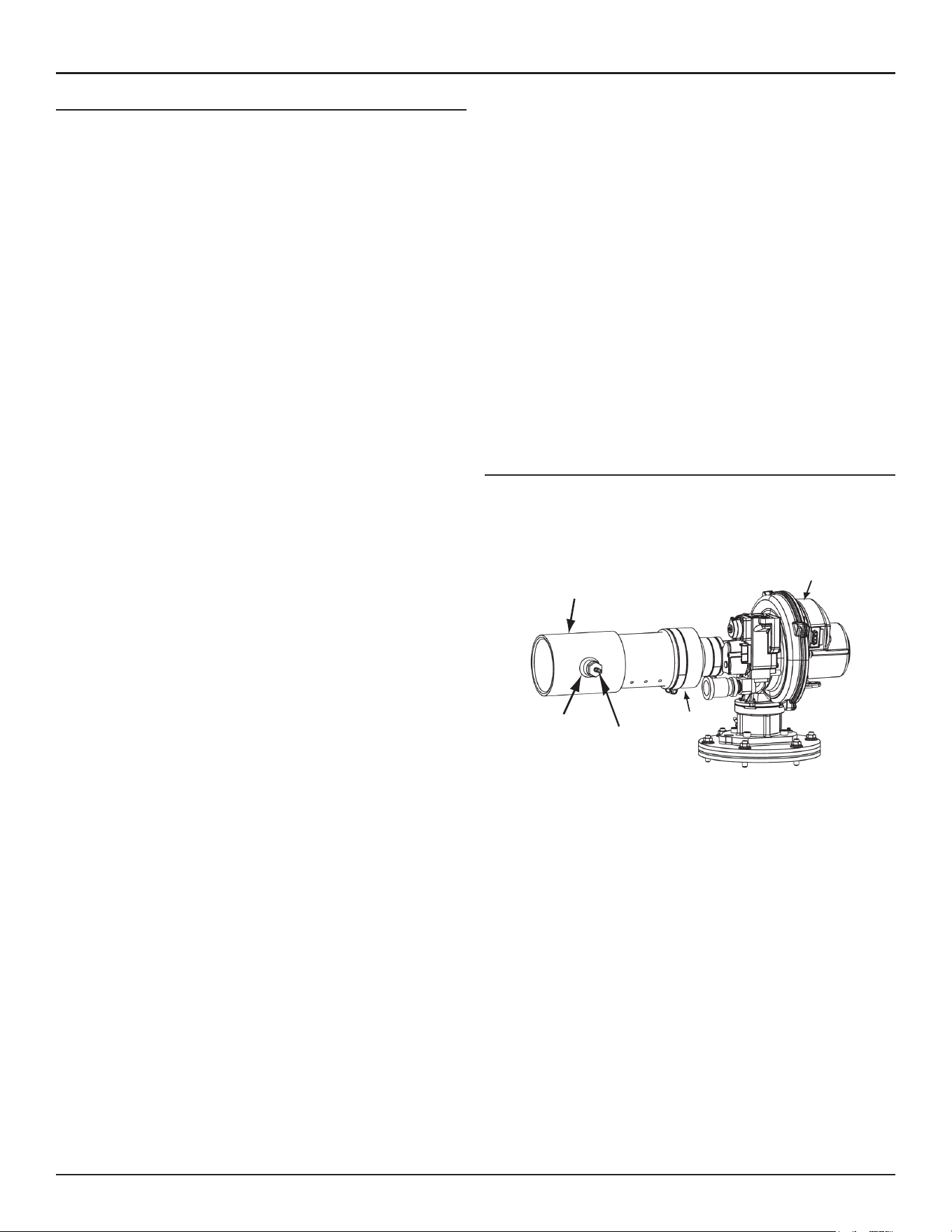
Venting Installation
High-Eciency Commercial Gas Water Heaters • 31
GENERAL VENTING INSTRUCTIONS
These instructions must be followed on all installations.
1. Do not install the water heater in a Power Vent configuration unless
there is adequate supply of fresh air, see
Air Requirements
(page 24).
If the installation space does not provide an adequate supply of fresh
air the water heater must be installed in a Direct Vent configuration.
2. If the water heater is to be installed in a beauty shop, barber shop,
cleaning establishment, a laundry with dry cleaning equipment or any
space with contaminated air it is imperative that the water heater(s)
be installed in a Direct Vent configuration so that all air for combustion
is derived from the outdoor atmosphere.
3. The vent and intake air piping must terminate outdoors.
4. The minimum clearance from combustible materials for the vent
(exhaust) and intake air piping shall be 0 inches. Vent piping passing
through a combustible wall or ceiling must be a continuous run (no
joints).
5. The water heater must be protected from freezing downdrafts during
shutdown periods.
6. The intake air and vent pipes
must not be combined
with pipes from
any other appliance.
7. Locate the water heater where the vent (exhaust) and intake air piping
will remain within the maximum equivalent lengths allowed. See
Venting Requirements
(page 32).
8. Do not install the vent or intake air piping in a manner that will allow
water to be trapped in the piping.
9. Vent pipes and air intakes must be pitched a minimum of a 1/4 inch
per foot back to the water heater (to allow drainage of condensate).
10. Do not anchor the vent or intake air pipe directly to framed walls, floors
or ceilings unless rubber isolation pipe hangers are used to prevent
vibration noise from being transmitted.
11. Use only approved vent/intake air pipe sizes and materials. See
Venting
Requirements
(page 32).
12. Use only factory-supplied vent and intake air, concentric or low profile
terminations. See
Venting Requirements
(page 32).
13. Do not locate the vent (exhaust) or intake air terminations where they
would be objectionable due to noise at the termination(s). This includes
locations close to or across from windows and doors.
14. Direct venting into dead air spaces such as alleys, atriums, and inside
corners can cause recirculation of flue gases. Recirculation of flue gases
will cause sooting, premature failure of the heat exchanger and icing
of the combustion air intake during severe cold weather. To prevent
the recirculation of flue gases, maintain as much distance as possible
between the intake air and vent terminations.
15. Do not locate the vent termination over public walkways or a public
area where condensate or vapor can cause a nuisance or ice hazard.
16. Ensure the screens in the factory-supplied terminations are securely
installed to prevent blockage in the vent system.
17. Stress levels in pipe/fittings can be significantly increased by improper
installation. If rigid pipe clamps are used to hold the pipe in place, or if
the pipe cannot move freely through a wall penetration, the pipe may
be stressed, or high thermal stresses may be formed when the pipe
heats up and expands. Install accordingly to minimize such stresses.
18. Ensure the intake air connection Tee fitting is oriented properly, see
page
Intake Air Connection
section for instructions.
19. Carefully read the
Venting Requirements
(page 32) and then proceed
to
COMMON VENTING
(page 34).
Intake Air Connection
The water heaters covered in this manual are factory equipped with a
unique Combustion Blower and intake air connection Tee fitting. The intake
air connection Tee fitting has a hose barb installed in the 1/2 inch branch
to connect the Blocked Intake Air switch sensing tube, see
Figure 17
.
COMBUSTION BLOWER
FACTORY INSTALLED
INTAKE AIR TEE FITTING
1/2 INCH BRANCH
HOUSE BARB FITTING
FOR BLOCKED INTAKE
AIR SWITCH SENSING
TUBE
FERNO COUPLING
Figure 17. Intake-Air Connection
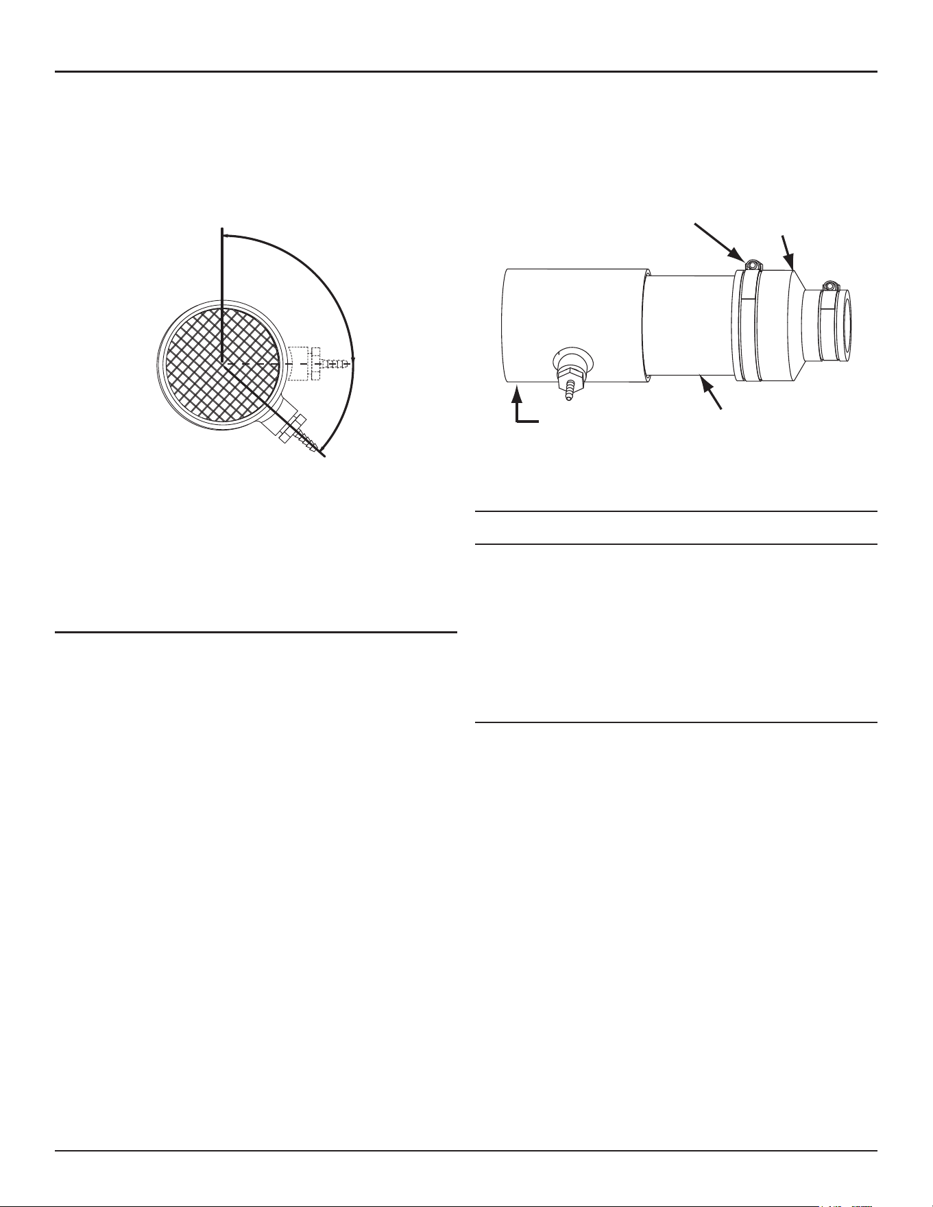
32 • High-Eciency Commercial Gas Water Heaters
Venting Installation
Ensure the hose barb installed in the Tee fitting
is not
facing down towards
the ground (180° - 6 o'clock position) before venting installation begins.
The barb fitting must be angled between 90° and no more than 130° as
shown in
Figure 18
. If the barb fitting is facing down, residual condensate
that occasionally forms in the intake air pipe can drain into the Blocked
Intake Air switch through the attached sensing tube and damage the
switch. This condition can also lead to Blocked Intake Air fault conditions
and associated control system lock outs.
90° TO 130°
END VIEW
Figure 18. Orientation of Intake Air Tee Fitting
The intake air Tee fitting is factory-installed with the 1/2 inch branch and
hose barb angled to the right at approximately 130° when viewed from
the end, see
Figure 18
. The Tee fitting's 1/2 inch branch and hose barb
must not be angled any lower (towards the ground) than this factory
specification. Angling higher, up to a 90° position, will not adversely affect
operation and is acceptable.
Inspect/Adjust Intake Air Tee Fitting
Inspect the angle of the Tee fitting's 1/2 inch branch and hose barb while
viewing from the end of the Tee. See
Figure 18.
If the angle of the Tee
fitting 1/2 inch branch and hose barb is lower than shown, adjustment
will be necessary. To adjust the intake air Tee fitting angle follow the steps
listed below.
1. Ensure the water heater is turned off at the on/off switch on the front
of the water heater.
2. Disconnect the Blocked Intake Air switch sensing tube, see
Figure 4
(page 12) for the location.
3. Loosen the large hose clamp on the Fernco coupling that connects the
intake air connection pipe to the Combustion blower. See
Figure 19
.
4. Adjust the angle of the Tee fitting so that the 1/2 inch branch and hose
barb are at the proper angle as shown in
Figure 18
.
5. Retighten the large hose clamp on the Combustion Blower intake air
Fernco coupling. Torque clamp to 24-30 in/lbs.
6. Reconnect the Blocked Intake Air switch sensing tube making sure the
sensing tube is securely connected at both ends and is not kinked.
LARGE HOSE CLAMP
PVC
INTAKE AIR
TEE FITTING
FERNCO
COUPLING
(TORQUE CLAMPS
TO 24 - 30 IN/LBS)
Figure 19. Intake Air Connection Pipe
VENTING REQUIREMENTS
Field-Supplied Fittings
Field-supplied fittings should be equivalent to the piping material being
installed. Field-installed/supplied fittings will add equivalent length to the
vent or intake air piping as indicated below. All field-supplied/installed
fittings and piping must be factored into the equivalent length calculations.
• 90° elbows (short or long radius) are equivalent to 5 linear feet (152
cm) of PVC pipe.
• 45° elbows (short or long radius) are equivalent to 2.5 linear feet (76
cm) of PVC pipe.
Primer and Cement
Tetrahydrofuran (THF) primer should be used to prepare the surfaces of
pipe and fittings for solvent welding. If CPVC pipe and fittings are used,
then the proper cement must be used for all joints, including joining the
pipe to the factory provided terminations (PVC material). PVC Materials
should use ASTM D-2564 Grade Cement; CPVC Materials should use ASTM
F-493 Grade Cement.
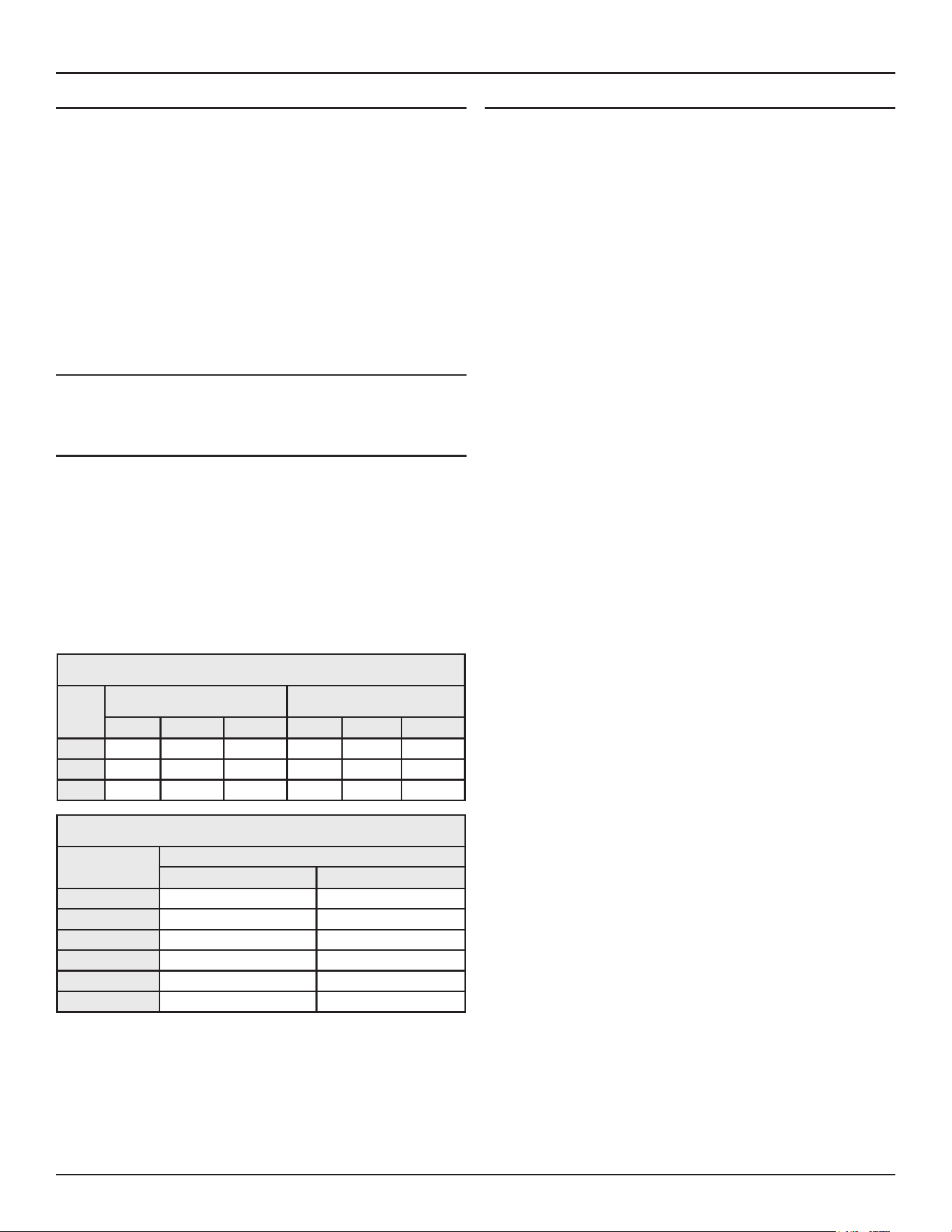
Venting Installation
High-Eciency Commercial Gas Water Heaters • 33
Pipe Size Requirements
The water heaters covered in this manual are certified for the use with two-,
three-, four-, and six-inch pipe for the vent (exhaust) and intake air piping.
Note: Install the pipe size required for the installed equivalent length of
each pipe independently. For example, on the 220 gallon model,
if the intake-air pipe will be 100 feet equivalent length or less and
the vent pipe will be more than 100 feet equivalent length; the
intake-air pipe must be installed using 4 inch pipe and the vent
must be installed using 6 inch pipe.
There is no minimum equivalent length requirement for the intake air pipe.
The minimum equivalent length requirement for the exhaust pipe is 7
feet for all models.
Maximum Number Of Elbows
The maximum number of elbows allowed varies according to the heater
input rating and pipe diameter. See
Table 7
and
Table 8
(page 33).
Factory-Supplied Fittings
The water heater ships with two factory-supplied 3-inch or 4-inch
terminations (PVC 45° elbows with debris screen). Factory-supplied vent
and intake air terminations, concentric, or low-profile terminations must
be used. Factory-supplied terminations and installed fittings (exhaust/
condensate elbow and intake air connection) add zero equivalent length
to the vent and intake air piping.
Note: For 220 gallon units: 3 inch vent and/ or intake pipe as well as 3
inch terminations previously used on older 300 and 399.9 kbtu/hr
models must be replaced with 4 inch or 6 inch pipe and 4 inch or
6 inch terminations depending on installed length.
Table 7. PVC/CPVC Equivalent Length and
Maximum Number of Elbows - 250 Gallon Models
Model
Maximum Equivalent Length, Feet
(Meters) Maximum Number of Elbows
2" Pipe 3" Pipe 4" Pipe 2" 3" 4"
150 50 (15.2) 45.72 (150) 200 (60.96) 4 4 6
199 40 (12.2) 45.72 (150) 200 (60.96) 4 4 6
250 20 (6.10) 150(45.72) 200 (60.96) 2 4 6
Table 8. PVC/CPVC Equivalent Length and
Maximum Number of Elbows - 220 Gallon Models
Number of 90°
Elbows Installed
Maximum Feet (Meters)
4 Inch Pipe 6 Inch Pipe
One (1) 95(28.9) 145(44.1)
Two (2) 90(27.4) 140(42.6)
Three (3) 85(25.9) 135(41.1)
Four (4) 80(24.3) 130(39.6)
Five (5) 75(22.8) 125(38.1)
Six (6) 70(21.3) 120(36.5)
Optional Concentric & Low Profile Terminations
The water heaters covered by this manual may be installed in a Direct Vent
configuration using a concentric termination or a low-profile termination.
Concentric and Low-Profile terminations must be ordered separately.
Contact your local distributor or contact Technical Support for assistance.
See the contact information label on the water heater.
The following are the part numbers for the different pipe diameters:
• Two-Inch Concentric Termination #100112869
• Two-Inch Low-Profile Termination #100187903
• Four-Inch Concentric Termination # 100111100 (used for both three-
and four-inch diameter piping)
• Three-Inch Low-Profile Termination # 100187887
• Four-Inch Low-Profile Termination # 100187888
• Six-Inch Concentric Termination # 100113124 (used for both 4 and 6
inch diameter piping)
• Six-Inch Low-Profile Termination # 100187889

34 • High-Eciency Commercial Gas Water Heaters
Venting Installation
COMMON VENTING
The water heaters covered by this manual may be installed using a common
horizontal direct vent kit. Contact Technical Support for more information
or to order. See the contact information label on the water heater.
VENTING INSTALLATION SEQUENCE
1. Read
General Venting Instructions
(page 31)
and
Venting
Requirements
(page 32) before proceeding. These instructions and
requirements must be followed on all installations.
2. Determine whether the water heater will be installed in a Power Vent
or Direct Vent configuration and which vent system arrangement will
be used for the installation. See the various venting arrangements in .
3. Proceed to the applicable instructions:
•
Power Vent Installation
(page 34).
•
Direct Vent Installation
(page 34).
POWER VENT INSTALLATION
1. Read the
General Venting Instructions
(page 31)
and
Venting
Requirements
(page 32) before proceeding. These instructions and
requirements must be followed in addition to the instructions below
that are specific for Power Vent configurations.
2. Determine which Power Vent arrangement will be used for the
installation; vertical or horizontal termination. See
Figure 45
and
Figure
46
(page 45).
3. Determine the vent pipe size for the installation. See
Venting
Requirements
(page 32).
4. Plan the layout of the vent piping backwards from the termination
point outdoors to the water heater. Layout the vent piping to use a
minimum of pipe and elbows.
5. Install the termination first.
• If the vent piping will terminate vertically, through a roof, see
Vertical Termination Installation
(page 36).
• If the vent piping will terminate horizontally, through a sidewall,
see
Horizontal Termination Installation
(page 37).
6. When installation of the termination is complete install necessary
piping and fittings to route the vent piping back to the water heater.
7. The vent pipe shall be supported properly to avoid bending or failure.
The water heater manufacturer recommends that the vent pipe be
supported every five feet (152 cm) of vertical run and every three feet
(91 cm) of horizontal run.
8. Do not install the vent piping in a manner that will allow water to be
trapped in the piping.
PIPE FIELD
SUPPLIED
ALUMINUM
EXHAUST/
CONDENSATE
ELBOW VENT
CONNECTION
FACTORY
INSTALLED
PIPE FIELD
SUPPLIED
REDUCER
FIELD SUPPLIED
VENT (EXHAUST) CONNECTION
Figure 20. Vent (Exhaust) Connection
9. All vent (exhaust) pipes shall be pitched a minimum of a 1/4 inch per
foot back to the water heater (to allow drainage of condensate).
10. If installing the same size vent pipe, connect the vent pipe to the exhaust
elbow on the water heater.
11. If installing a different diameter pipe, transition to smaller diameter
pipe at the exhaust elbow on the water heater as shown in
Figure 20
(page 34). The field installed pipe between the exhaust elbow and
the reducer coupling should be 18 inches (45 cm) or less in length.
DIRECT VENT INSTALLATION
1. Read the
General Venting Instructions
(page 31) and
Venting
Requirements
(page 32) before proceeding. These instructions and
requirements must be followed in addition to the instructions below
that are specific for Direct Vent configurations.
2. Determine which Direct Vent arrangement will be used for the
installation. There are seven Direct Vent arrangement options. See
Figure 47
through
Figure 53
(page 45)
3. Determine vent and intake air pipe size to be used for the installation.
See
Venting Requirements
(page 32).
4. Plan the layout of the vent and intake air piping backwards from the
termination point outdoors to the water heater. Layout the vent and
intake air piping to use a minimum of pipe and elbows.
5. Install the terminations first.
• If standard terminations are being used and the intake air or
vent piping will terminate vertically, through a roof, see
Vertical
Termination Installation
(page 36).
• If standard terminations are being used and the intake air or
vent piping will terminate horizontally, through a sidewall, see
Horizontal Termination Installation
(page 37).
• If a concentric termination(s) will be used see
Concentric
Termination Installation Preparation
(page 40).
• If a low-profile termination will be used see
Low-Profile Vent
Termination installation
(page 44).
6. When installation of the termination(s) is complete, Install necessary
piping and fittings to route the intake air and vent piping back to the
water heater.
7. The intake air and vent piping shall be supported properly to avoid
bending or failure. The water heater manufacturer recommends that
the vent and intake air piping be supported every 5 feet (152 cm) of
vertical run and every 3 feet (91 cm) of horizontal run.
8. Do not install the vent or intake air piping in a manner that will allow
water to be trapped in the piping.
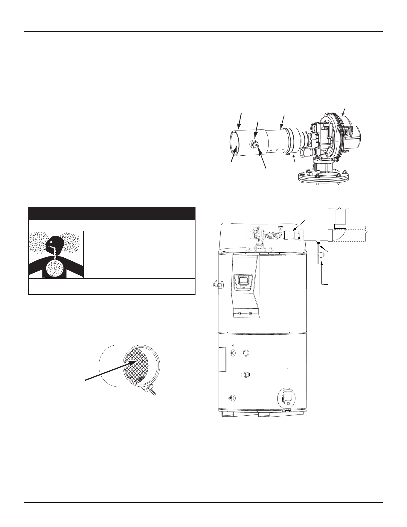
Venting Installation
High-Eciency Commercial Gas Water Heaters • 35
9. A field-supplied condensate Tee fitting and drain hose shall be installed
in the intake air piping near the water heater in colder climates with
heavy snow accumulations and in areas that regularly experience high
humidity. The drain hose should be routed to an adequate floor drain
separate from any other condensate drains. See
Figure 23
(page 35).
Note:
Snow being pulled into the intake air piping and then melting
can lead to excessive amounts of water accumulation and
damage water heater components. Warm, humid outdoor
air can lead to excessive condensation inside the intake air
piping and may also damage water heater components.
10. The intake air and vent (exhaust) piping must be pitched a minimum
of a 1/4 inch per foot back to the water heater (to allow drainage of
condensate).
11. If installing the same size vent pipe connect the vent pipe to the exhaust
elbow on the water heater.
12. If installing a different diameter vent pipe, transition to pipe at the
exhaust elbow on the water heater as shown in
Figure 20
(page 34).
The field installed pipe between the exhaust elbow and the reducer
coupling should be 18 inches (45 cm) or less in length.
13. Ensure the Intake Air Screen on the Intake Air Connection to the water
heater is removed before connecting the intake air pipe to the water
heater. See
Figure 21
(page 35).
Breathing carbon monoxide can cause brain damage or death. Always read
and understand instruc�on manual.
• Do not obstruct water heater air intake.
• Gas and carbon monoxide detectors are
available.
• Install water heater in accordance with the
instruction manual and applicable codes.
⚠
WARNING
Breathing Hazard - Carbon Monoxide Gas
Note:
Do not leave the screen inside the Intake Air Connection for
Direct Vent installations. Once the intake air pipe is installed
the screen will be hidden from view and may become
clogged with debris over time. This will cause improper
combustion and may also lead to Blocked Intake Air fault
conditions and associated control system lock outs.
INTAKE AIR
SCREEN
(remove for Direct Vent)
Figure 21. Intake Air Screen
14. If installing the same size intake air pipe connect the intake air pipe to
the intake air connection on the water heater.
15. If installing a 2 or 4 inch diameter intake air pipe, transition to three-inch
pipe at the intake air connection on the water heater as shown in
Figure
22
. The field installed three-inch pipe between the intake air connection
and the reducer coupling should be 18 inches (45 cm) or less in length.
16. if installing 6" air intake pipe, transition to 4" pipe at the intake air
connection on the water heater as shown in figure 20. The field installed
4" pipe between the intake air connection and the 6x4 inch reducer
coupling should be 18" or less in length.
COMBUSTION BLOWER
FACTORY INSTALLED
INTAKE AIR TEE FITTING
1/2 INCH BRANCH
HOUSE BARB FITTING
FOR BLOCKED INTAKE
AIR SWITCH SENSING
TUBE
FERNO COUPLING
INTAKE AIR
PIPE
FACTORY INSTALLED
Figure 22. Intake Air Connection
Install the tee tting as close to the water heater
intake air connection as possible
Factory
Intake Air
Connection
Field Supplied Tee
with Hose Barb
Fitting Installed
Connect eld sup-
plied exible drain
hose to barb t-
ting and form a
loop water trap in
the drain hose.
Run the drain hose
to a suitable oor
drain separately
from other con-
densate drains.
Figure 23. Intake Air Condensate Tee Installation
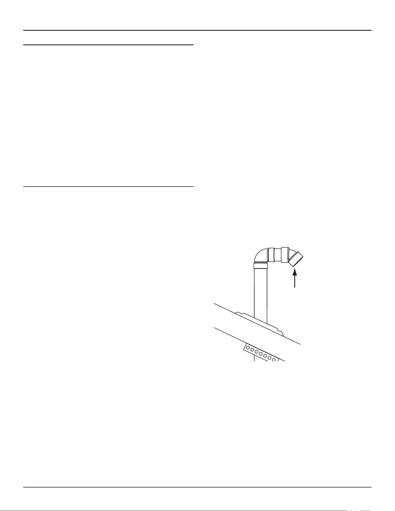
36 • High-Eciency Commercial Gas Water Heaters
Venting Installation
Direct Vent Air Intake Moisture Protection
The air intake piping in a direct vent system will normally not have any
moisture accumulation in it. However, in certain cases, moisture may
build up and needs to be drained. Typical situations include, but are not
limited to:
• Cold outdoor temperature, particularly if the air inlet is short
• Heater being used mostly for space heating
• Air inlet pipe has vertical rise near the heater
Installations with any of these conditions are required to provide a moisture
drain with a trap that flows to a waste drain. See
Figure 23
. A horizontal
section of the air inlet pipe, near the heater should include a tee and a hose
barb fitting to drain the water. The tee should be as close to the heater
as is practical. The drain tubing in any installation should have a loop trap
and flow to an appropriate waste drain. The air intake drain line must be
entirely separate from the exhaust vent outlet condensate line.
VERTICAL TERMINATION INSTALLATION
1. Determine the location for the termination(s).
2. If installing only the vent (exhaust) piping in a Power Vent configuration
vertically through the roof; ensure that all exterior vertical clearance
requirements shown in
Figure 25
(page 37)
and
Figure 26
(page 37)
are being maintained. These clearances and those cited by local and
national codes must be maintained.
Note:
On flat roof installations the vent termination must be a
minimum of 24 inches (60 cm) above any parapet, vertical
wall or structure within 10 feet (3 m) horizontally. See
Figure
26
.
3. If installing both intake air and vent piping in a Direct Vent configuration
vertically through the roof; ensure that all exterior vertical clearance
requirements shown in
Figure 25
(page 37)
and
Figure 26
(page 37)
are being maintained. These clearances and those cited by local and
national codes must be maintained.
Note:
On flat roof installations the intake air and the vent
terminations must be a minimum of 24 inches (60 cm) above
any parapet, vertical wall or structure within 10 feet (3 m)
horizontally. See
Figure 26
(page 37).
4. If installing only vent piping in a Power Vent configuration vertically
through the roof the following instructions must be followed:
• The vent termination must be oriented facing downward as
shown in
Figure 25
and
Figure 26
(page 37)
.
• The bottom edge of vent termination must be a minimum of 12
inches (30 cm), 18 inches (45 cm) in Canada, above average or
expected snow level as shown in
Figure 25
(page 37).
5. If installing both intake air and vent piping in a Direct Vent configuration
vertically through the roof the following instructions must be followed:
• The intake air and vent pipes must penetrate the same side of
the roof as shown in
Figure 27
(page 37).
• The intake air and vent terminations must be oriented facing
downward and in the same direction as shown in
Figure 27
(page
37).
• The intake air and vent terminations must have a minimum
separation of 24” (61 cm) measured on center line as shown in
Figure 27
(page 37). In colder climates this separation should
be increased to at least 48 inches (122 cm).
• The bottom edge of the intake air and vent terminations must be
a minimum of 12 inches (30 cm), 18 inches (45 cm) in Canada,
above the average or expected snow level as shown in
Figure 25
and
Figure 27
(page 37).
6. When the intake air and/or vent piping from multiple water heaters will
terminate in the same location the vent terminations can be grouped
together in close proximity 0 inches/touching. Intake air terminations
can also be grouped together in close proximity 0 inches/touching.
• The distance between the closest vent and intake air
terminations must be a minimum of 24 inches (61 cm) as shown
in
Figure 27
(page 37). In colder climates this separation
should be increased to at least 48 inches (122 cm).
7. See
Table 9
for the hole size to cut, where the pipe(s) will pass through
the roof.
Note:
Beware of concealed wiring and piping when cutting through
the roof.
8. Suspend the pipe(s) through center of hole using field-supplied metal
strapping or equivalent support materials as shown in
Figure 25
(page
37).
9. Slide a roof boot or equivalent flashing over the pipe and secure roof
boot or equivalent flashing to roof and seal around the flashing as
shown in
Figure 25
,
Figure 26
(page 37)
,
and
Figure 27
(page 37).
10. Install the factory-supplied intake air and/or vent termination(s) using
field-supplied pipe and one field-supplied 90° elbow as shown in
Figure
25
(page 37)The short section of pipe that connects between the
field-supplied 90° elbow and the factory-supplied termination must
not be excessive in length. The exposed portion of this pipe shall be
no more than 2 inches (5 cm).
11. Return to
Power Vent Installation
(page 34) or
Direct Vent Installation
(page 34) to complete the installation of the intake air and/or vent
piping between the termination(s) and the water heater.
INTAKE AIR AND
VENT (EXHAUST) TERMINATIONS
45° ELBOW WITH RECESSED
DEBRIS SCREEN
Figure 24. Standard Factory-supplied Terminations
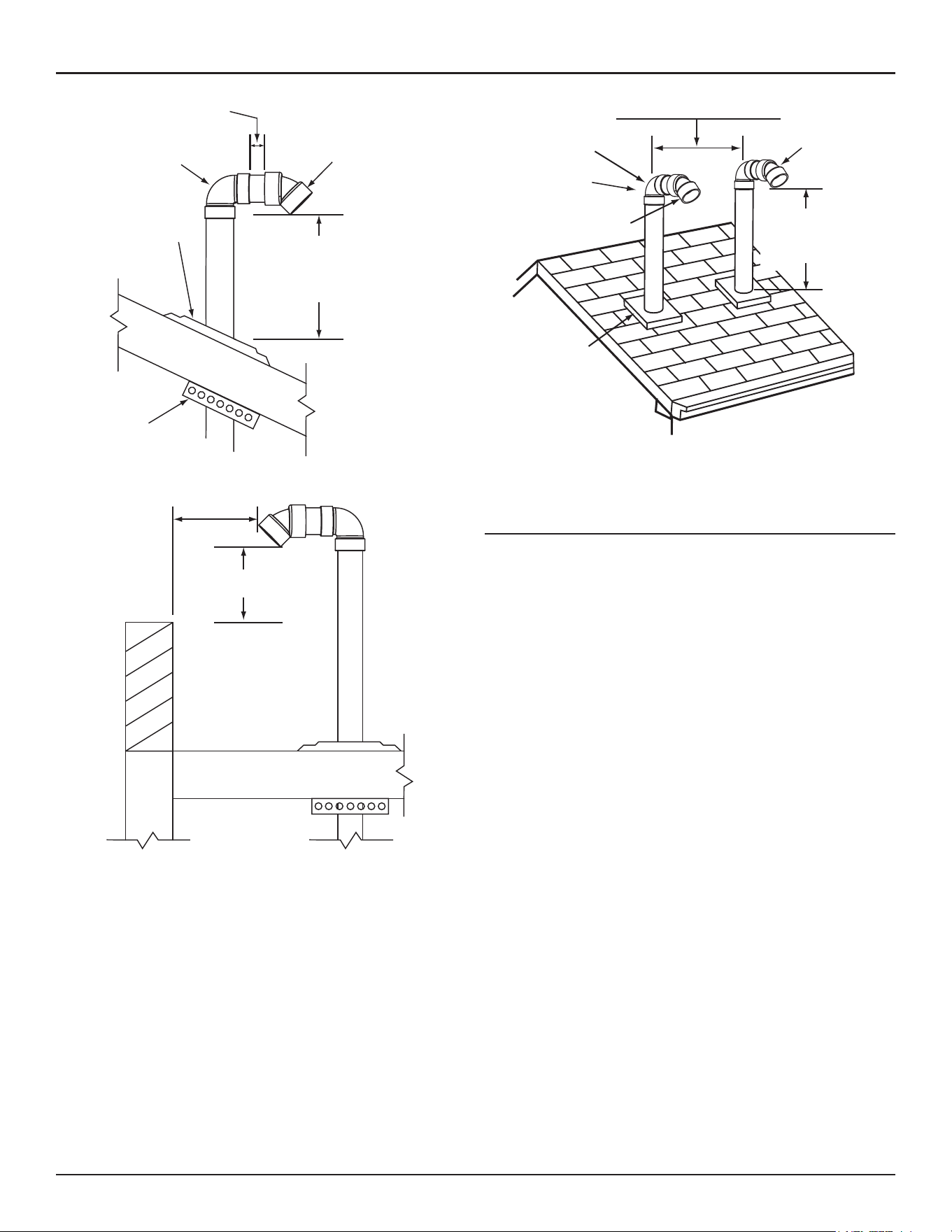
Venting Installation
High-Eciency Commercial Gas Water Heaters • 37
2” (5 cm)
MAXIMUM
FACTORY SUPPLIED
STANDARD TERMINATION
POINTED DOWN TOWARDS
THE GROUND
VERTICAL TERMINATION(S) INSTALLATION
INTAKE AIR AND/OR VENT (EXHAUST)
FIELD
SUPPLIED
90° ELBOW
FIELD
SUPPLIED
STRAP/SUPPORT
FIELD SUPPLIED
PLUMBING
ROOF BOOT
OR FLASHING
MAINTAIN 12” (30 cm)
18” (45 cm) FOR CANADA
MINIMUM CLEARANCE
ABOVE HIGHEST ANTICIPATED
SNOW LEVEL.
Figure 25. Vertical Termination(s) Installation: Intake Air and/or Vent (Exhaust)
INTAKE AIR AND/OR VENT
TERMINATION(S) MUST BE A
MINIMUM OF 24 INCHES (60 cm)
ABOVE ANY PARAPET, VERTICAL
WALL OR STRUCTURE WITHIN
10 FEET (3 m) HORIZONTALLY.
VERTICAL TERMINATION(S) FLAT ROOF CLEARANCE
INTAKE AIR AND/OR VENT (EXHAUST)
24 INCHES (60 cm)
MINIMUM HEIGHT ABOVE
IF LESS THAN
10 FEET (3 m)
Figure 26. Vertical Termination Flat Roof Clearance - Intake Air and/or Vent
(Exhaust)
VERTICAL TERMINATION - DIRECT VENT
STANDARD TERMINATIONS
24 INCHES (61 cm) MINIMUM
48 INCHES (122 cm) IN COLDER CLIMATES
FACTORY SUPPLIED
STANDARD TERMINATIONS
POINTED DOWNWARD
FIELD
SUPPLIED
90° ELBOW
VENT (EXHAUST)
TERMINATION
INTAKE AIR
TERMINATION
FIELD SUPPLIED
PLUMBING
ROOF BOOTS
OR FLASHINGS
MAINTAIN 12” (30 cm)
18” (45 cm) FOR CANADA
MINIMUM CLEARANCE
ABOVE HIGHEST
ANTICIPATED SNOW LEVEL.
Figure 27. Vertical Termination - Direct Vent: Standard Terminations
HORIZONTAL TERMINATION INSTALLATION
1. Determine the location for the termination(s).
2. If installing only vent (exhaust) piping in a Power Vent configuration
through a sidewall; ensure that all exterior sidewall clearance
requirements for the termination, shown in
Figure 54
(page 47),
are being maintained. These clearances and those cited by local and
national codes must be maintained.
3. If installing both the intake air and the vent piping in a Direct Vent
configuration through a sidewall; ensure that all exterior sidewall
clearance requirements for the terminations, shown in
Figure 55
(page
48), for the vent and the intake air termination are being maintained.
These clearances and those cited by local and national codes must be
maintained.
4. If installing both an intake air and vent termination in a Direct Vent
configuration through a sidewall there must be a minimum of 24
inches (61 cm) separation, measured on vertical center line, between
the intake air and vent terminations, see
Figure 28
.
Note:
In colder climates this separation should be increased to
at least 48 inches (122 cm) between intake air and vent
termination or any other appliance vent that discharges
moisture-laden air such as clothes dryers. This will reduce
possibility of frost over from side winds blowing exhaust
vapors to the intake air termination and is recommended for
Canadian installations.
5. If installing both intake air and vent terminations in a Direct Vent
configuration through a sidewall, the intake air and vent terminations
must be installed at the same elevation measured on horizontal center
line - see
Figure 28
.
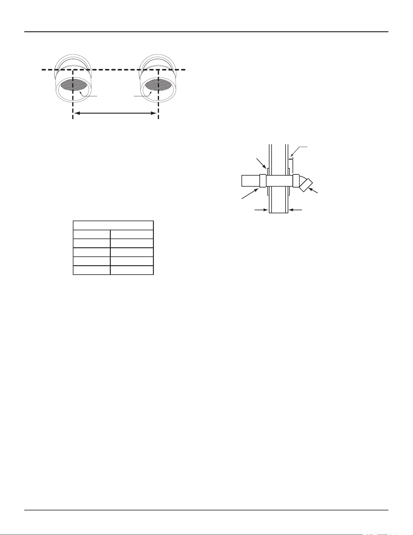
38 • High-Eciency Commercial Gas Water Heaters
Venting Installation
VENT (EXHAUST)
TERMINATION
INTAKE AIR
TERMINATION
INSTALL ON
ELEVATION
CENTERLINE
24 INCHES (61 cm) MINIMUM
48 INCHES (122 cm) IN COLDER CLIMATES
KEEP INTAKE AND VENT
TERMINATION SCREENS
CLEAR OF DEBRIS
Figure 28. Side-Wall Termination - Direct Vent: Standard Terminations
6. When the intake air and/or vent piping from multiple water heaters
will terminate at the same location through a sidewall, the vent
terminations can be grouped together in close proximity - 0 inches/
touching. The intake air terminations can also be grouped together in
close proximity - 0 inches/touching.
• However, the distance between the closest vent and intake air
terminations must be a minimum of 24 inches (61 cm). In colder
climates this separation should be increased to at least 48 inches
(122 cm). See
Figure 28
(page 38).
7. Cut a hole in the wall through which pipes will pass as follows:
Table 9. Vent Hole Size
Pipe Size Hole Size
2" 3" (7.6 cm)
3" 4" (10 cm)
4" 5" (13 cm)
6" 7" (18 cm)
Note:
Beware of concealed wiring and piping when cutting through
the wall.
8. Cut a length(s) of pipe being installed 3.5 inches (8.9 cm) to 9.5 inches
(24.1 cm) longer than the wall thickness at the opening. See
Figure 29
(page 38).
Note:
Vent Termination – exhaust gases of this water heater are
less than 140°F. In cold climates water vapor in the exhaust
gases will condense into a cloud of vapor where the vent
exits the building. This vapor can gradually discolor exterior
building surfaces. The vent termination should be located
where this vapor cloud and potential discoloration are
not a concern. Extending the exposed vent piping up to a
maximum of 6 inches (15.2 cm) from the wall helps vapor
from being trapped along a building’s face. To avoid this
problem, the vent can also be terminated vertically through
the roof, see
Vertical Termination Installation
(page 36).
9. Cement the intake air and/or vent termination to the section(s) of pipe
cut to length in the above Step.
10. The wall plates for the 3-inch or 4-inch vent pipe are included with the
heater. Wall plates for two-inch or six-inch vents are field-supplied.
Slide the included metal wall plate(s) over the pipe(s) to stop against
the intake air and/or vent termination. Place some silicone caulking
(field-supplied) on the back of the wall plate(s) to secure it to the wall.
11. Working from outside, slide the pipe and termination(s) assembled in
the above steps through the wall. Ensure the termination(s) is pointed
down towards the ground. See
Figure 29
.
INTERIOR WALL EXTERIOR WALL
FROM
WATER
HEATER
COUPLING
METAL PLATES
INSTALL INSIDE
AND/OR OUTSIDE
FACTORY SUPPLIED
STANDARD TERMINATION
POINTED DOWN
TOWARDS THE GROUND
INCREASE EXPOSED VENT
PIPING UP TO A MAXIMUM
OF 6 INCHES (15.2 cm) FROM
WALL TO HELP PREVENT VAPOR
FROM DISCOLORING THE WALL
SURFACE IN COLDER CLIMATES
Figure 29. Side-Wall Termination Installation:
Intake Air and/or Vent (Exhaust)
12. Place a bead of silicone caulking (field-supplied) around the gap
between the installed pipe(s) and the wall. Apply enough to fill the gap
between the pipe(s) and wall.
13. Press the wall plate flush against the outside wall.
14. Working from the inside apply enough silicone caulking on the back
of the interior wall plate(s) to hold it in place and slide the wall plate
over the installed pipe(s).
15. Install a coupling to the end of the pipe(s) inside the building. Before
the silicone caulking has time to completely set go outside the building
and ensure the termination(s) is still pointing down towards the ground.
See
Figure 29
.
16. Return to
Power Vent Installation
(page 34) or
Direct Vent Installation
(page 34) to complete the installation of the intake air and/or vent
piping between the termination(s) and the water heater.
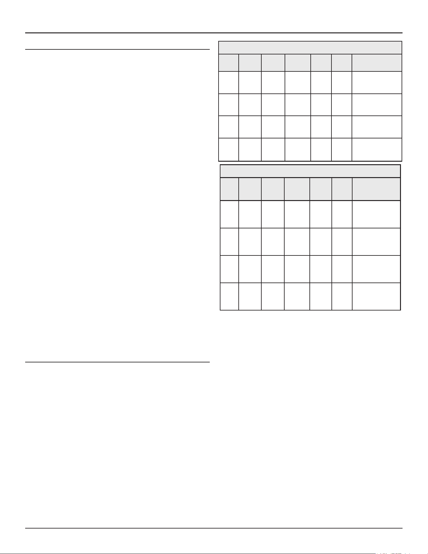
Venting Installation
High-Eciency Commercial Gas Water Heaters • 39
POLYPROPYLENE INSTALLATIONS
The water heater has been approved to be installed with Polypropylene
vent material as shown in
Table 10
and
Table 11
. The approved application
of single wall, non-flexible, non-concentric Polypropylene vent material
is offered by two specific manufacturers (Centrotherm ECO Systems
and DuraVent Polypropylene. These listed products must be installed by
following the vent manufacturer’s instructions. See
Table 7
and
Table 8
(page 33)
to determine the maximum pipe length and number of elbows
that can be used.
Verify equivalent lengths with vendor.
Insulation should not be used on Polypropylene venting materials. The
use of insulation will cause increased vent wall temperatures, which could
result in vent pipe failure.
Use only the adapters and vent system listed in Tables below. DO NOT mix
vent systems of different types or manufacturers. Failure to comply could
result in severe personal injury, death, or substantial property damage.
Installations must comply with applicable national, state, and local codes.
For Canadian installation, Polypropylene vent must be listed as a
ULC-S636
approved system. If Polypropylene vent is not required by your local code,
you may use either PVC or CPVC pipes for your water heater that allows
non-metallic venting material installations.
Polypropylene vent systems do not use cement to connect the pipe
and elbow sections. They use a push-together gasket-seal method. Do
not attempt to connect Polypropylene with sealant cement. All vent
connections MUST be secured by the vent manufacturer's joint connector.
The installer must use a specific vent starter adapter at the flue connection.
The adapter is supplied by the vent manufacturer to adapt to its vent
system.
In order to be in full compliance with
UL 1738
or
ULC-S636
and to meet
the requirements of the water heater manufacturer, you must use the
metal joint connector rings, available from the Polypropylene vent
manufacturer, to stiffen the joints of two-inch, three-inch, four-inch, and
six-inch diameter pipes.
Table 10. M & G Duravent Polypro
Nominal
Pipe
Dia.
Flue
Outlet
Adapter
Adapter
Connector
Ring
Connector
90°
Elbow
Vent
Mate-
rial Terminal(s)
2" 2PPS-AD PPS-PAC 2PPS-LB
2PPS-
E90B
2PPS
2PPS-E45B for
Exhaust;
2PPS-E45B for intake
(Direct Vent Only)
3" 3PPS-AD PPS-PAC 3PPS-LB
3PPS-
E90B
3PPS
3PPS-E45B for
Exhaust;
3PPS-E45B for Intake
(Direct Vent only)
4" 4PPS-AD PPS-PAC 4PPS-LB
4PPS-
E90B
4PPS
4PPS-E45B for
Exhaust;
4PPS-E45B for Intake
(Direct Vent only)
6"
6PPS-
06PVCM-
6PPF
PPS-PACL 6PPS-LBC
6PPS-
E90
PPS
6PPS-E45 for Exhaust;
6PPS-E45 for Intake
(Direct Vent only)
Table 11. Centrotherm InnoFlue SW
Nomi-
nal
Pipe
Dia.
Flue
Outlet
Adapter
Adapter
Connec-
tor
Ring
Connector
90°
Elbow
Vent
Mate-
rial Terminal(s)
2"
ISA-
GL0202
IAFC02 IANS02
IS-
ELL0287
ISVL02
ISELL0245UV for
Exhaust;
ISELL0245UV for
intake (Direct Vent
only)
3"
ISA-
GL0303
IAFC03 IANS03
IS-
ELL0387
ISVL03
ISELL0345UV for
Exhaust;
ISELL0345UV for
Intake (Direct Vent
only)
4"
ISA-
GL0404
IAFC04 IANS04
IS-
ELL0487
ISVL04
ISELL0445UV for
Exhaust;
ISELL0445UV for
Intake (Direct Vent
only)
6"
ISA-
GL0606
IAFC06 IANS06 ISEL0687
Polypro-
pylene
ISELL0645UV for
Exhaust;
ISELL0645UV for
Intake (Direct Vent
only)
AL29-4C
®
VENT INSTALLATIONS
(AL29-4C
®
is a registered trademark of Allegheny Technologies, Inc.)
The water heaters covered by this manual are approved to be installed with
AL29-4C
®
stainless steel vent material using parts from the manufacturers
listed in
Table 12 and Table 13
below. These listed systems must be installed
using the vent manufacturer’s instructions including their listed clearances
to combustible and noncombustible materials. See
Table 7
and
Table 8
(page 33)
for the maximum and minimum equivalent linear vent lengths
and number of elbows that may be used. However, use
Table 12 and Table
13
below to find the appropriate equivalent linear vent lengths for the
AL29-4C
®
elbows.
Note: The equivalent lengths of the AL29-4C
®
elbows are different than
those from smooth walled plastic vents. Consult
Table 12 and Table
13
for the correct equivalent linear vent lengths.
Listed vent systems composed of AL29-4C
®
must not mix parts from the
different manufacturers. The joints of these products are sealed by internal
gaskets. Do not use any other type of sealant. When assembling these
vent systems, follow the vent manufacturer’s instructions for cleaning and
lubricating the joints, if required. Each section must be locked together
using the method supplied by the vent manufacturer.
The water heaters covered by this manual are approved to be installed
using the approved vent terminations shown in this manual. This means
that, the installer must use the adapter listed in Tables 9 and 10 and a short
piece of PVC pipe to complete the end of the vent system with an approved
termination. In Canada, the PVC pipe length must be listed to ULC636.
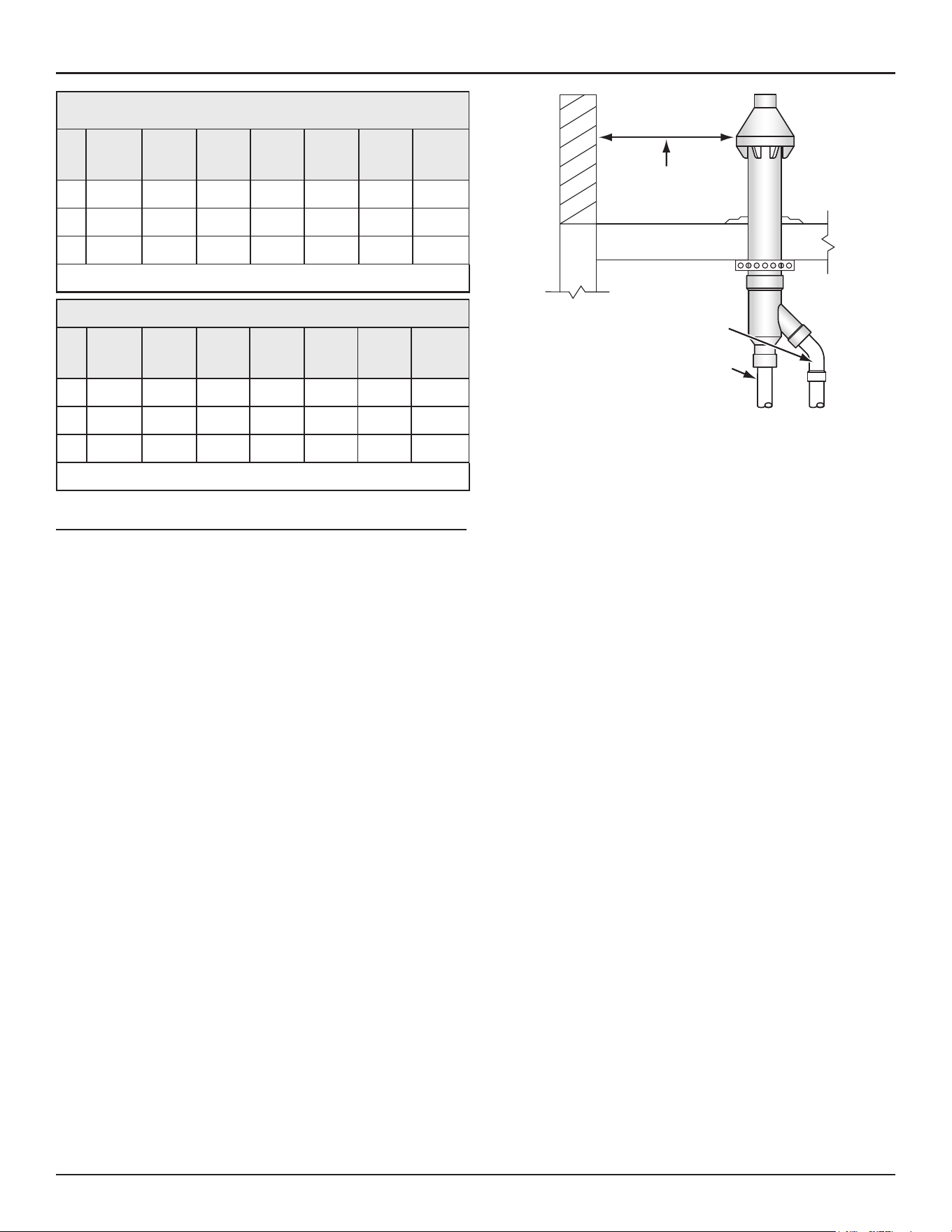
40 • High-Eciency Commercial Gas Water Heaters
Venting Installation
Table 12. HeatFab Saf-T Vent AL29-4C
®
Vent System Parts
Dia.
Flue Outlet
Adapter
*Straight
Pipe (3’
Section) 45° Elbow
Equivalent
Linear
Length,
45° Elbow 90° Elbow
Equivalent
Linear
length,
90° Elbow
Adapter to
PVC
3" 9301 PVC 9307 9311 5 feet 9314 10 feet 9353CPVC
4" 9401 PVC 9407 9411 5 feet 9414 10 feet 9454CPVC
6" 9601 PVC 9607 9611 5 feet 9614 10 feet 9656CPVC
*Consult vent manufacturer’s catalog for other available lengths.
Table 13. Duravent FasNSeal AL29-4C
®
Vent System Parts
Dia.
Flue
Outlet
Adapter
*Straight
Pipe (3’
Section) 45° Elbow
Equivalent
Linear
Length,
45” Elbow 90° Elbow
Equivalent
Linear
Length,
90° Elbow
Adapter to
PVC
3” 810005378 FSVL3603 FSELB4503 5 feet FSELB9003 10 feet 810009530
4” 810005545 FSVL3604 FSELB4504 5 feet FSELB9004 10 feet 810009529
6” 810005225 FSVL3606 FSELB4506 5 feet FSELB9006 10 feet 810005572
*Consult vent manufacturer’s catalog for other available lengths.
CONCENTRIC TERMINATION INSTALLATION PREPARATION
1. Concentric terminations must be ordered separately.
• All 250 gallon models must use the four-inch concentric
termination; Part Number: 100111100 for both three-inch and
four-inch vent diameters or the two-inch terminal (100153586 )
for two-inch diameter pipe.
• All 220 gallon models must use the six-inch concentric
termination for both four-inch and six-inch vent diameters: Part
number 100113124.
Contact your local distributor or call the parts department phone
number on the back cover of this manual to order concentric
terminations.
2. Determine the location for the termination.
Note:
Roof termination is preferred since it is less susceptible to
damage, has reduced chances to intake contaminants and
vent vapors are less visible.
3. When installing a concentric termination vertically through the
roof; ensure that all exterior vertical clearance requirements for the
concentric termination, shown in
Figure 32
(page 41)
are being
maintained. These clearances and those cited by local and national
codes must be maintained.
4. When installing a concentric termination vertically through a flat roof,
the termination's vent cap must be a minimum of 10 feet (3 m) away
from any parapet, vertical wall or structure as shown in
Figure 30
.
CONCENTRIC TERMINATION(S)
MUST BE A MINIMUM OF 10 FEET
(3 m) AWAY FROM ANY PARAPET,
VERTICAL WALL OR
STRUCTURE.
VENT PIPE
INTAKE AIR PIPE
Figure 30. Concentric Termination - Flat Roof Clearance
Note:
If this required 10 foot (3 m) distance to a parapet,
vertical wall or structure cannot be maintained, standard
terminations must be used. See
Vertical Termination
Installation
(page 36).
5. When installing a concentric termination through a sidewall; ensure that
all exterior sidewall clearance requirements for the termination, shown
in
Figure 55
(page 48), are being maintained. These clearances and
those cited by local and national codes must be maintained.
6. When installing multiple concentric terminations vertically through a
roof or horizontally through a sidewall ensure the required clearances
between terminations and groupings of multiple terminations are
maintained. See
Multiple Concentric Termination Clearances
(page
42)
for more information.
7. Cut a 5 inch (13 cm) diameter hole for the four-inch concentric terminal,
a three-inch hole for the two-inch terminal, or a seven-inch diameter
hole for six-inch concentric terminations where the termination will
pass through the wall or roof.
Note:
Beware of concealed wiring and piping when cutting through
the wall or roof.
When installing multiple concentric terminations vertically through
the roof in the same location, the termination caps for all concentric
terminations must be at the same height measured from ground.
See
(page 43).
8. Determine if the concentric termination will need to be shortened to
accommodate required clearances or to ensure all vent caps are at the
same height when installing multiple terminations vertically through
the roof in the same location.
• See
Figure 31
(page 41)
for the minimum lengths allowed for
the concentric termination.
Note:
When shortening the length of the termination, carefully
measure and cut the larger (intake air) pipe first. Cut the
same amount of pipe from the smaller (vent) pipe.
Note:
Lengthening of the Concentric Vent Termination is not
permitted.
9. Proceed to
Concentric Termination Installation
.
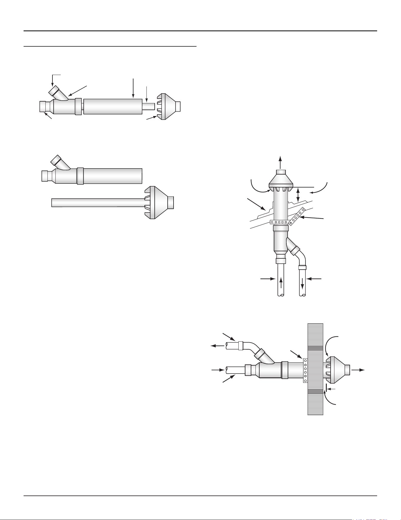
Venting Installation
High-Eciency Commercial Gas Water Heaters • 41
CONCENTRIC TERMINATION INSTALLATION
Assemble and install the concentric termination. Refer to
Figure 31
,
Figure
32
and
Figure 33
for these instructions:
VENT PIPE
INTAKE AIR CONNECTION
VENT CONNECTION
INTAKE AIR PIPE
Y FITTING ASSEMBLY
VENT CAP
VENT PIPE ASSEMBLY
MINIMUM ALLOWABLE LENGTH 25 INCHES (64 cm)
INTAKE AIR PIPE MAY BE SHORTENED
MINIMUM ALLOWABLE LENGTH 12 INCHES (30 cm)
VENT CAP
INTAKE AIR PIPE
Y FITTING
VENT PIPE MAY BE SHORTENED
Figure 31. Concentric Termination Kit
1. Cement the Y fitting to the larger diameter intake air pipe.
2. Slide the intake air pipe and Y fitting assembly from inside the building
through the hole cut for the termination in the roof or sidewall. Ensure
no foreign materials such as insulation accumulate inside the assembly.
3. Secure the intake air Y fitting assembly using field-supplied metal
strapping or equivalent support materials.
4. On installations installed through the roof, slide a field-supplied
plumbing boot or roof flashing over the intake air Y-fitting assembly
and secure it to the roof.
5. Seal around the plumbing boot or roof flashing.
6. Cement the vent cap onto the vent pipe. Alternately a field-supplied
stainless steel screw may be used to secure the two components
together when field disassembly is desired for cleaning. A pilot hole
must be drilled for the screw to prevent damage/cracking of the vent
cap and/or vent pipe.
7. Install the vent cap/vent pipe assembly into the intake air Y fitting
assembly. Ensure the small diameter vent pipe is cemented and
bottomed in the Y fitting.
8. Use the appropriate method for connecting intake air and vent piping
to the termination as follows:
• For two-inch installations, connect the pipe directly to the two-
inch termination. For three-inch installations connect the pipe
directly to the three-inch termination. Do not mix different pipe
and termination sizes.
• For four-inch pipe installations - connect the piping to the
concentric termination using field-supplied 4" x 3" reducer
couplings and short sections of three-inch pipe (18 inches or
less).
• For six-inch pipe installations, connect the piping to the
concentric termination using field-supplied 6" x 4" reducer
couplings as needed.
Do not exceed the maximum equivalent vent length listed in
Table 7
and
Table 8
(page 33).
Cement all fittings and pipe in place.
9. Return to
Direct Vent Installation
(page 34)
to complete the
installation of the intake air and vent piping between the concentric
termination and the water heater.
NOTE: SECURING STRAP
MUST BE FIELD INSTALLED
TO PREVENT MOVEMENT
OF TERMINATION KIT
MAINTAIN 12” (30 cm)
18” (45 cm) FOR CANADA
MINIMUM CLEARANCE
ABOVE HIGHEST ANTICIPATED
SNOW LEVEL. MAXIMUM OF
24” (60 cm) ABOVE ROOF.
ROOF FLASHING
(field supplied)
STRAP
(field supplied)
VENT
PIPE
INTAKE
AIR PIPE
COMBUSTION
AIR
VENT
Figure 32. Concentric Termination - Vertical Installation
INTAKE AIR PIPE
STRAP
(field supplied)
VENT PIPE
COMBUSTION
AIR
VENT
1 inch(2.54 cm)
MAXIMUM
NOTE: SECURING STRAP MUST BE
FIELD INSTALLED TO PREVENT
MOVEMENT OF TERMINATION KIT
IN SIDEWALL.
Figure 33. Concentric Termination - Side-Wall Installation
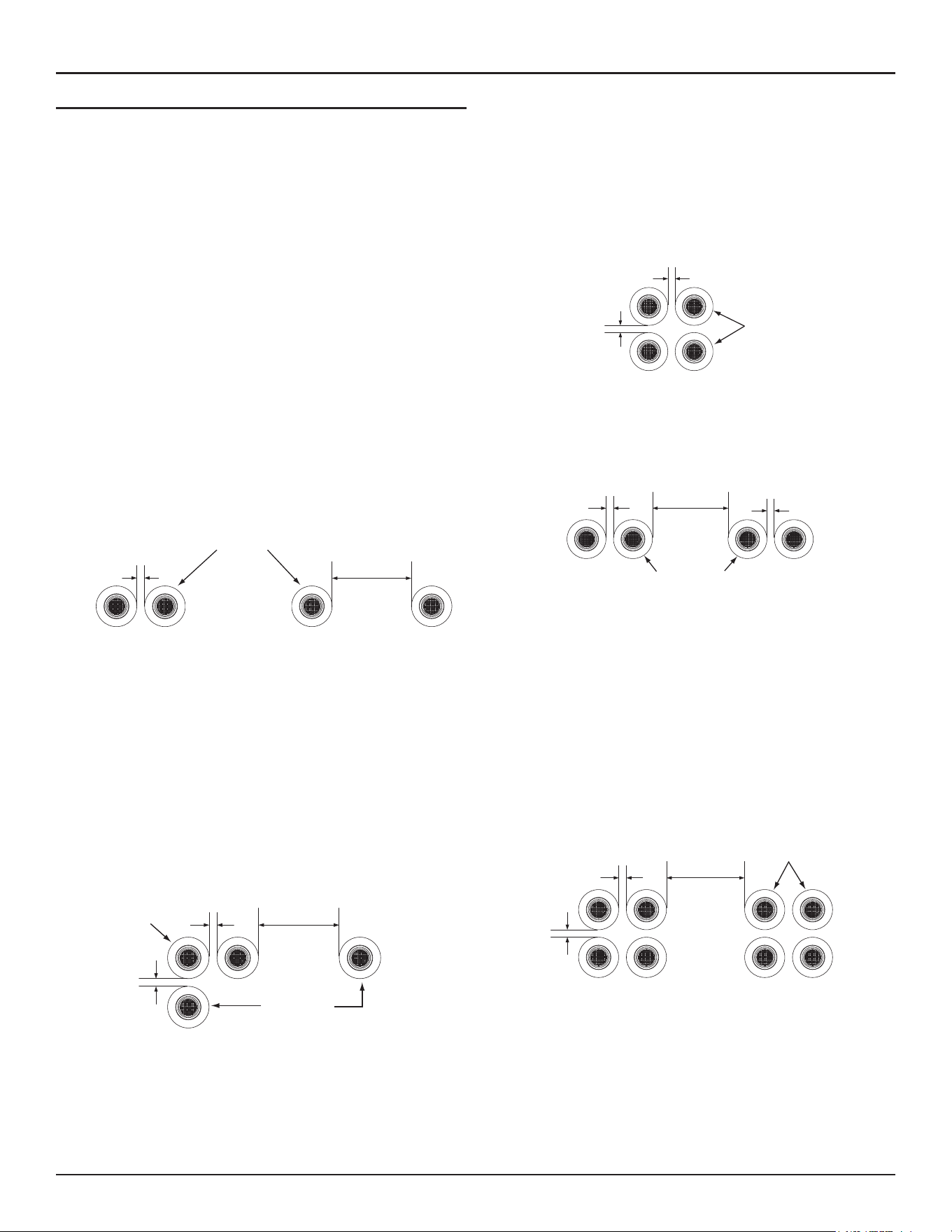
42 • High-Eciency Commercial Gas Water Heaters
Venting Installation
Multiple Concentric Termination Clearances
When installing multiple concentric terminations vertically through a
roof or horizontally through a sidewall ensure the required clearances
(separation) between terminations are maintained. Ensure multiple
terminations are arranged or grouped as required.
Note: These clearances must be maintained to prevent the recirculation
of vent (exhaust) gases to the intake air. Clearances are measured
between the edges of the concentric termination caps.
When installing multiple concentric terminations through a roof or through
a sidewall the clearances shown in
Figure 34
must be maintained.
See
Multiple Concentric Termination Arrangements
(page 43).
Close Proximity & Standard Clearance
1. The clearance between multiple termination caps must be zero inches
(touching) to a maximum of two inches (5 cm), dimension A -
Figure
34
, when installing concentric terminations in close proximity. See
Figure 39
(page 43).
2. The clearance between multiple termination caps must be increased
to a minimum of 24 inches (61 cm), dimension B -
Figure 34
, when
installation in close proximity (above) is not possible. This is the
standard clearance.
A
OR
B
A = 0 - 2 INCHES (0 - 5 cm)
CONCENTRIC
TERMINATION CAPS
END VIEW
TWO CONCENTRIC TERMINATIONS
(THROUGH A ROOF OR SIDEWALL)
B = 24 INCHES (61 cm)
OR GREATER
CLOSE PROXIMITY STANDARD CLEARANCE
Figure 34. Two Concentric Terminations
- Through a Roof or Sidewall
Three Concentric Terminations
1. When installing three concentric terminations through a roof or through
a sidewall the third termination may be installed in close proximity as
indicated by dimension A in
Figure 35
.
2. If close proximity installation of the third termination is not possible
the third termination may be installed as indicated by dimension B in
Figure 35
.
A = 0 - 2 INCHES (0 - 5 cm)
CLOSE PROXIMITY
CONCENTRIC
TERMINATION
CAPS END VIEW
THIRD
TERMINATION
THREE CONCENTRIC TERMINATIONS
(THROUGH A ROOF OR SIDEWALL)
A
A B
B = 24 INCHES (61 cm)
OR GREATER
Figure 35. Three Concentric Terminations
-Through a Roof or Sidewall
Four Concentric Terminations
1. When installing four concentric terminations through a roof or through
a sidewall in close proximity they may be arranged into stacked rows of
two as shown in
Figure 36
(page 42)
or lateral rows of two as shown
in
Figure 37
(page 42).
2. Four is the maximum number of concentric terminations that may be
installed in a group where all terminations are in close proximity as
shown in
Figure 36
.
A
A
A = 0 - 2 INCHES (0 - 5 cm)
CLOSE PROXIMITY
CONCENTRIC
TERMINATION
CAPS END VIEW
FOUR CONCENTRIC TERMINATIONS
(THROUGH A ROOF OR SIDEWALL)
Figure 36. Four Concentric Terminations
- Through a Roof or Sidewall
A B
A
FOUR CONCENTRIC TERMINATIONS
(THROUGH A ROOF OR SIDEWALL)
A = 0 - 2 INCHES (0 - 5 cm)
CLOSE PROXIMITY
B = 24 INCHES (61 cm)
OR GREATER
CONCENTRIC
TERMINATION
CAPS END VIEW
Figure 37. Four Concentric Terminations
- Through a Roof or Sidewall
Groups Of Terminations
1. When installing multiple groups of concentric terminations through a
roof or through a sidewall in close proximity, they can be installed into
stacked groups of four as shown in
Figure 38
. Lateral groups of four as
shown in
Figure 37
may be a more convenient installation arrangement
for multiple groups depending on available space.
A
A B
A = 0 - 2 INCHES (0 - 5 cm)
CLOSE PROXIMITY
CONCENTRIC
TERMINATION
CAPS END VIEW
EIGHT CONCENTRIC TERMINATIONS
(THROUGH A ROOF OR SIDEWALL)
B = 24 INCHES (61 cm)
OR GREATER BETWEEN
GROUPS OF FOUR
Figure 38. Eight Concentric Terminations
- Through a Roof or Sidewall
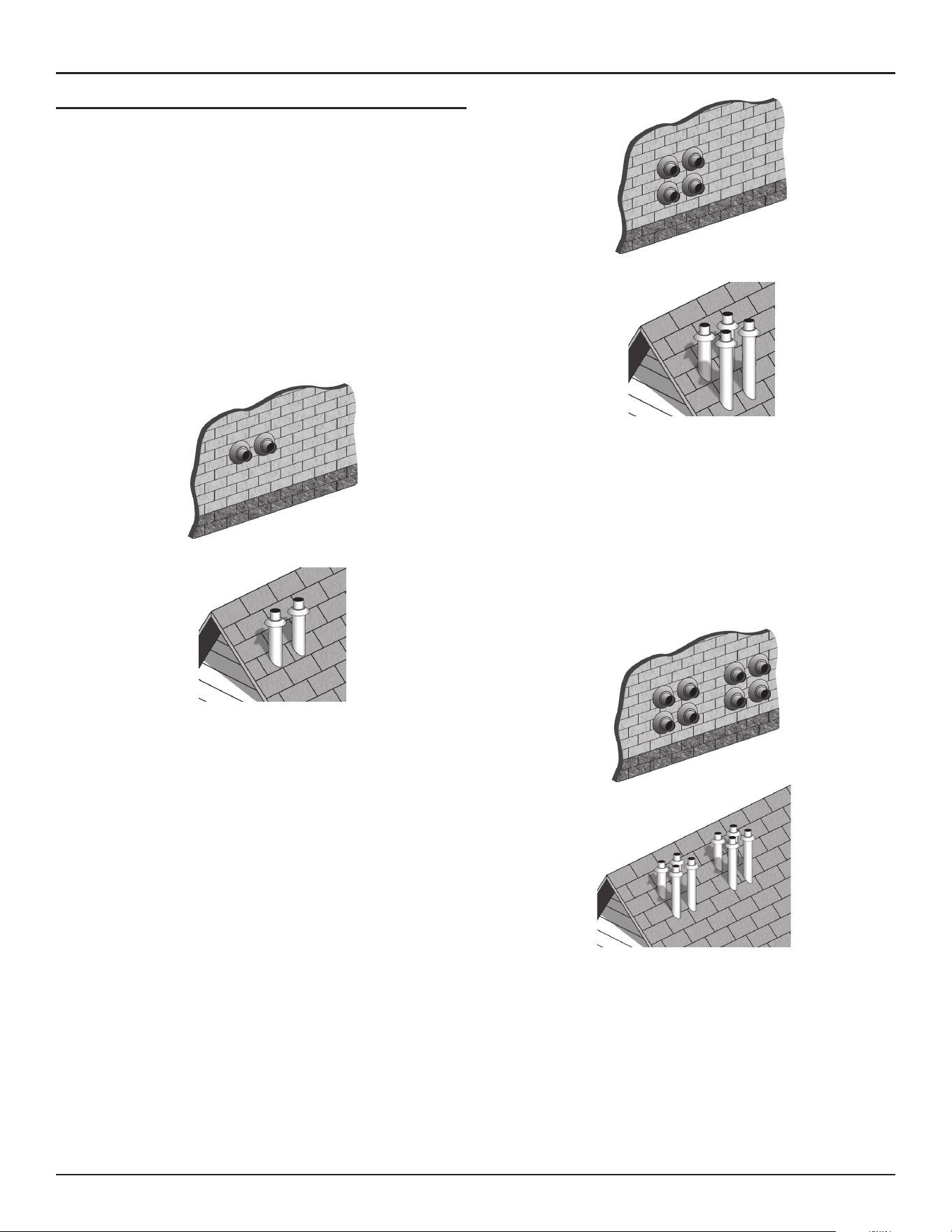
Venting Installation
High-Eciency Commercial Gas Water Heaters • 43
Multiple Concentric Termination Arrangements
The illustrations on this page show some of the installation arrangements
for multiple concentric terminations that are allowed.
See
Multiple Concentric Termination Clearances
(page 42)
for detailed
information on clearances and additional arrangement options.
Note: When multiple concentric terminations are installed through a
roof in the same location all termination caps must be at the same
height measured from the ground.
Two Concentric Terminations
Two concentric terminations may be installed in close proximity as shown
in
Figure 39
or with standard clearances when this arrangement is not
possible. See
Figure 34
(page 42)
for detailed information on clearances.
See
Figure 35
(page 42)
when installing three concentric terminations.
SIDEWALL
ROOF
Figure 39. Two Concentric Terminations
(Side-Wall And Roof)
Four Concentric Terminations
Four concentric terminations may be installed in close proximity as shown
in
Figure 40
. See
Figure 36
(page 42) and
Figure 37
(page 42) for
detailed information on clearances and additional arrangement options.
SIDEWALL
ROOF
Figure 40. Four Concentric Terminations (Side-Wall and Roof)
Eight Concentric Terminations
Eight concentric terminations may be installed in two stacked groups of
four, in close proximity, as shown in
Figure 41
. See
Figure 38
(page 42)
for detailed information on clearances.
Lateral groups of four as shown in
Figure 37
(page 42) may be a more
convenient installation arrangement for multiple groups depending on
available space.
SIDEWALL
ROOF
Figure 41. Eight Concentric Terminations
(Side-Wall and Roof)
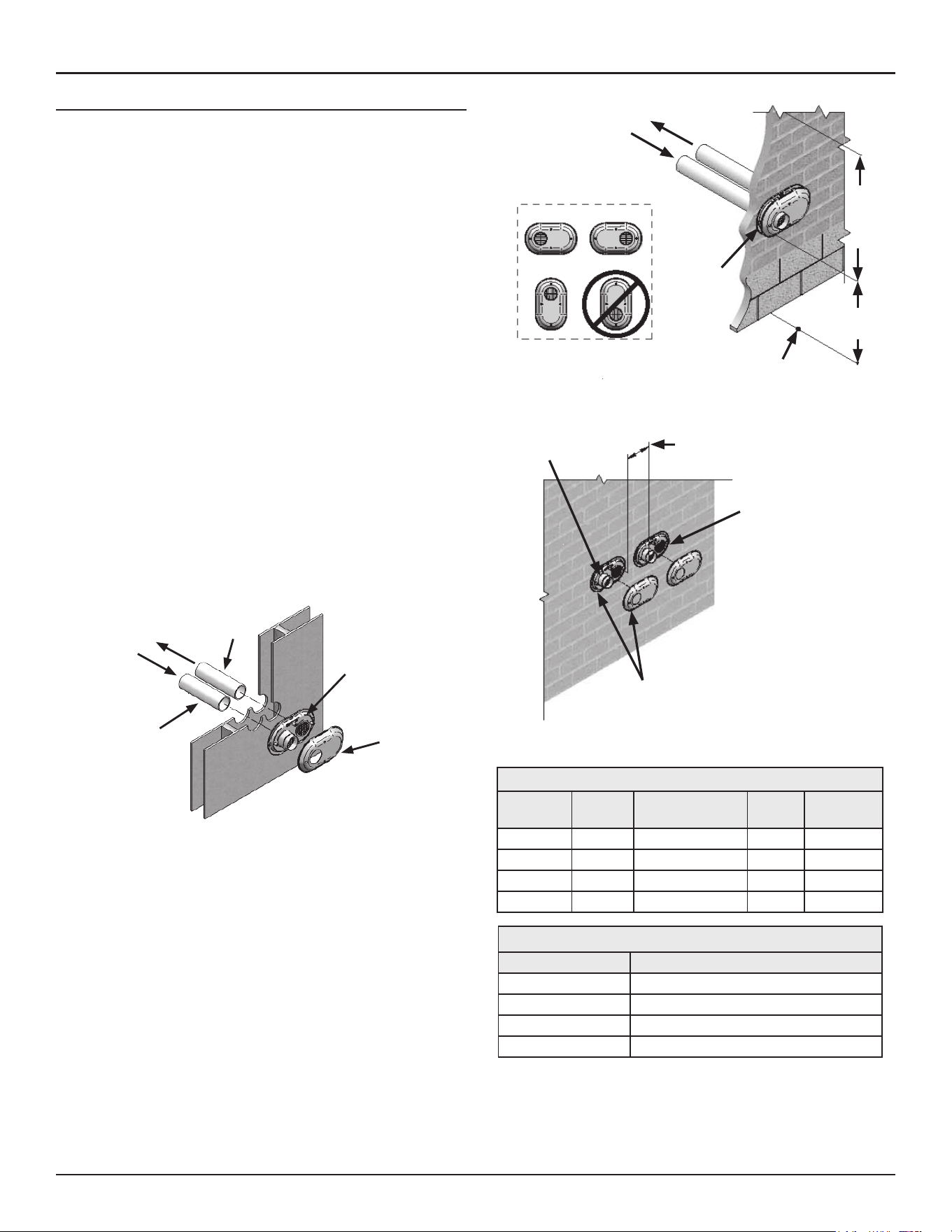
44 • High-Eciency Commercial Gas Water Heaters
Venting Installation
LOW-PROFILE VENT TERMINATION INSTALLATION
This water heater is certified for sidewall direct venting with IPEX System
636 Low Profile Vent Kit. Follow instructions below for proper installations.
1. All termination kits must be located and installed in accordance with
local building code and
CSA B149.1 Natural Gas and Propane Installation
Code
.
2. Once the proper location has been determined, cut two holes in the
wall large enough to accommodate the pipe. See the
Table 14
(page
44)
for pipe diameters and distance between hole centers.
3. Slide both the intake and exhaust pipes through the holes. Solvent
cement both pipes to the base of the vent termination kit, follow
the solvent cementing procedures outlined in the
IPEX System 636
Installation Guide
, which is available on the web www.ipexinc.com.
4. To fasten the base to the wall, use the supplied screws and anchors. A
3/16” (5 mm) hole, that is 1-3/16” (30 mm) deep, will need to be drilled
for the anchors. Locate the anchor hole using the base as a template.
5. Screw the cap to the base using the supplied screws.
6. Once the vent termination and pipes are secured, the wall penetrations
will need to be sealed from the interior using a PVC-compatible sealant
material.
7. All vent pipes and air inlets must terminate at the same height to
avoid the possibility of severe personal injury, death, or substantial
property damage.
8. Operate the heater through one heat cycle to ensure combustion-
air and vent pipes are properly connected to the concentric vent
termination.
Vent Base
Vent Cap
Air Inlet
Piping
Vent (Exhaust)
Piping
Figure 42. Inlet and Vent Flow in Low-Profile Vent Installation
To Heater Intake
Air Connection
From Heater Vent
Pipe Connection
Vent/Air
Termination
12”
Min to
Over-
Hang
12”
Min
Grade or
Snow Line
Possible Orientations
Figure 43. Low-Profile Vent Clearances
12” Min between Edge of Air Inlet
and Adjacent Vent
(Exhaust) Outlet
Air Inlet
Vent/Air
Termination
Vent (Exhaust)
Figure 44. Multiple Low-Profile Vent Clearance
Table 14. Low Profile Termination Kits - Dimensions
Kit Number
IPEX
Part Num-
ber Description
Pipe
Outside
Diameter
Hole Spacing
(Center to
Center)
100187903 196984 2″ Flush Mount Vent Kit 2.375" 5.63"
100187887 196985 3″ Flush Mount Vent Kit 3.5″ 5.63″
100187888 196986 4″ Flush Mount Vent Kit 4.5″ 5.63″
100187889 196080 6″ Flush Mount Vent Kit 6.61″ 7.63″
Table 15. Contents of Low Profile Termination Kit
Qty Item Description
1 Base (two holes)
1 Cap (one hole)
8 Stainless Steel Screws
4 Plastic Anchors

Venting Installation
High-Eciency Commercial Gas Water Heaters • 45
VENTING ARRANGEMENTS
Figure 45. Power Vent Vertical Figure 46. Power Vent Horizontal
Figure 47. Direct Vent Vertical
Figure 48. Direct Vent Horizontal Figure 49. Direct Vent Vertical Vent
Horizontal Intake
Figure 50. Direct Vent Horizontal Vent
Vertical Intake
*Direct Vent combustion air intake drains are required in certain situations. See
Direct Vent Air Intake Moisture Protection
(page 35).
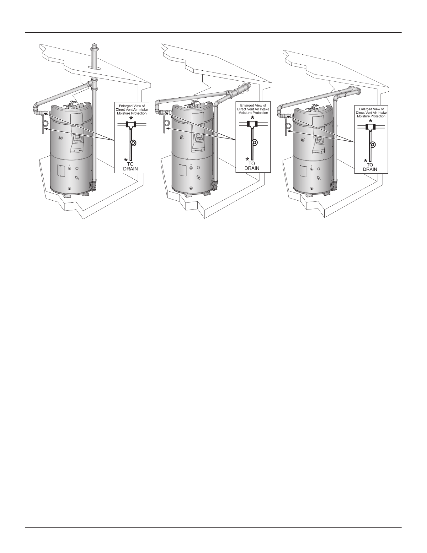
46 • High-Eciency Commercial Gas Water Heaters
Venting Installation
Figure 51. Direct Vent Vertical Concentric
Figure 52. Direct Vent Horizontal Concentric
Figure 53. Direct Vent Horizontal Low-Profile
*Direct Vent combustion air intake drains are required in certain situations. See
Direct Vent Air Intake Moisture Protection
(page 35).
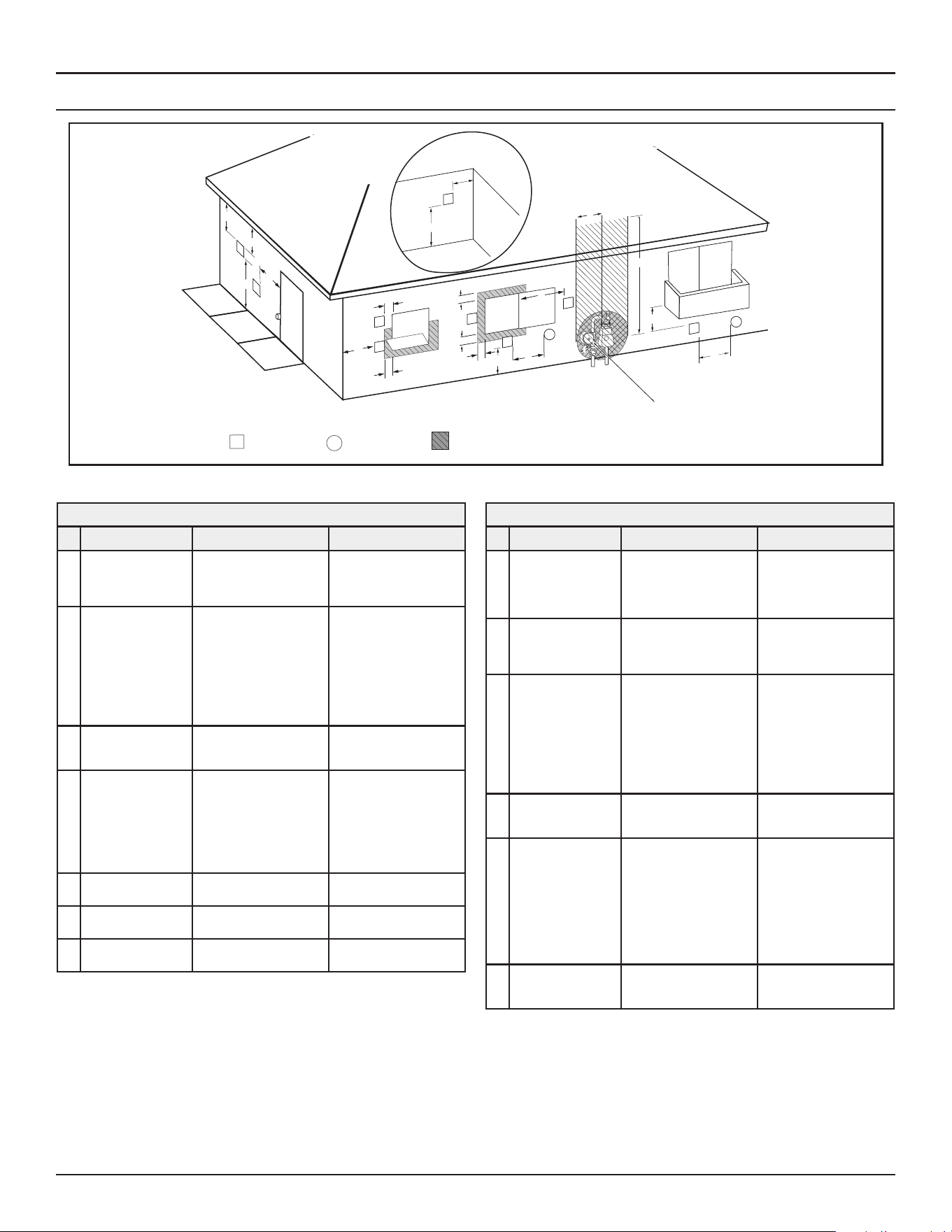
Venting Installation
High-Eciency Commercial Gas Water Heaters • 47
TERMINATION CLEARANCES SIDEWALL POWER VENT
Fixed
Closed
Operable
Fixed
closed
Operable
B
V
V
V
V
V
V
V
V
C
B
B
X
A
M
K
Regulator vent outlet
In the event no
regulator is present,
H and I can be
disregarded
.
V
Legend:
= Vent terminal
X
= Air supply inlet
= Area where terminal is not permitted
B
B
J
F
X
B
L
E
D
Inside
corner detail
V
A
G
H
15 ft
I
Figure 54. Power Vent Using Room Air
Termination Clearances for Sidewall Power Vent
Type of Clearance Canadian Installations
1
US Installations
2
A
Clearance above
grade, veranda,
porch, deck or
balcony
12 inches (30 cm) 12 inches (30 cm)
B
Clearance to window
or door that may be
opened
• 6 in (15 cm) for appli-
ances ≤ 10,000 Btuh
(3 kW)
• 12 in (30 cm) for ap-
pliances > 10,000 Btuh
(3 kW) and ≤ 100,000
Btuh (30 kW),
• 36 in (91 cm) for appli-
ances > 100,000 Btuh
(30 kW)
• 6 in (15 cm) for appli-
ances ≤ 10,000 Btuh
(3 kW)
• 9 in (23 cm) for appli-
ances >10,000 Btuh (3
kW) and ≤ 50,000 Btuh
(15 kW)
• 12 in (30 cm) for ap-
pliances > 50,000 Btuh
(15 kW)
C
Clearance to
permanently closed
window
12 inches (30 cm)* 12 inches (30 cm)*
D
Vertical clearance
to ventilated soffit
located above the
terminal within a
horizontal distance
of 2 feet (61 cm)
from the center line
of the terminal
12 inches (30 cm)* 12 inches (30 cm)*
E
Clearance to unven-
tilated soffit
12 inches (30 cm)* 12 inches (30 cm)*
F
Clearance to outside
corner
2 feet (60 cm)* 2 feet (60 cm)*
G
Clearance to inside
corner
18 inches (45 cm)* 18 inches (45 cm)*
Termination Clearances for Sidewall Power Vent
Type of Clearance Canadian Installations
1
US Installations
2
H
Clearance to each
side of center line
extended above
meter/regulator
assembly
3 ft (91 cm) within a
height of 15 ft (4.6 m)
Clearance in accordance
with local installation
codes and the require-
ments of the gas supplier
I
Clearance to service
regulator vent outlet
3 ft (91 cm)
Clearance in accordance
with local installation
codes and the require-
ments of the gas supplier
J
Clearance to a non
mechanical air sup-
ply inlet into build-
ing or combustion
air inlet to any other
appliance
• 6 in (15 cm) for appli-
ances ≤ 10,000 Btuh
(3 kW)
• 12 in (30 cm) for ap-
pliances > 10,000 Btuh
(3 kW) and ≤ 100,000
Btuh (30 kW)
• 36 in (91 cm) for appli-
ances >100,000 Btuh
(30 kW)
• 6 in (15 cm) for appli-
ances ≤ 10,000 Btuh
(3 kW)
• 9 in (23 cm) for appli-
ances >10,000 Btuh (3
kW) and ≤ 50,000 Btuh
(15 kW)
• 12 in (30 cm) for ap-
pliances > 50,000 Btuh
(15 kW)
K
Clearance to a
mechanical air sup-
ply inlet
6 feet (1.83 m)
3 feet (91 cm) above
if within 10 feet (3 m)
horizontally
L
Clearance above
paved sidewalk or
paved driveway
located on public
property
7 feet (2.13 m)†
7 ft (2.13 m) for me-
chanical draft systems
(Category I appliances);
vents for Category II and
IV appliances cannot
be located above public
walkways or other areas
where condensate or va-
por can cause a nuisance
or hazard
M
Clearance under ve-
randa, porch, deck,
or balcony
12 inches (30 cm) ‡ 12 inches (30 cm) ‡
1. In accordance with the current
CSA B149.1, Natural Gas and Propane Installation Code.
2. In accordance with the current
ANSI Z223.1/NFPA 54, National Fuel Gas Code
.
† A vent shall not terminate directly above a sidewalk or paved driveway that is located
between two single family dwellings and serves both dwellings, where it can cause
hazardous frost or ice accumulations on adjacent property surfaces.
‡ Permitted only if veranda, porch, deck, or balcony is fully open on a minimum of two
sides beneath the floor.
* Clearance in accordance with local installation codes and the requirements of the gas
supplier and the manufacturer’s installation instructions
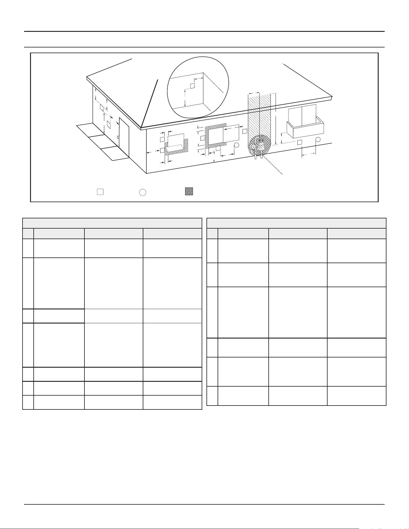
48 • High-Eciency Commercial Gas Water Heaters
Venting Installation
TERMINATION CLEARANCES SIDEWALL DIRECT VENT
Fixed
Closed
Operable
Fixed
closed
Operable
B
V
V
V
V
V
V
V
V
C
B
B
X
A
M
K
Regulator vent outlet
In the event no
regulator is present,
H and I can be
disregarded
.
V
Legend:
= Vent terminal
X
= Air supply inlet
= Area where terminal is not permitted
B
B
J
F
X
B
L
E
D
Inside
corner detail
V
A
G
H
15 ft
I
Figure 55. Direct Vent Using Outside Air
Termination Clearances for Sidewall Direct Vent
Type of Clearance
Canadian Installations
1
US Installations
2
A
Clearance above
grade, veranda, porch,
deck or balcony
12 inches (30 cm) 12 inches (30 cm)
B
Clearance to window
or door that may be
opened
• 6 in (15 cm) for appli-
ances ≤ 10,000 Btuh
(3 kW)
• 12 in (30 cm) for ap-
pliances > 10,000 Btuh
(3 kW) and ≤ 100,000
Btuh (30 kW),
• 36 in (91 cm) for appli-
ances > 100,000 Btuh
(30 kW)
• 4 feet (1.2 m) below or
to side of opening;
• 1 foot (30 cm) above
opening
C
Clearance to perma-
nently closed window
6 inches (15 cm)* 6 inches (15 cm)*
D
Vertical clearance
to ventilated soffit
located above the
terminal within a
horizontal distance of
2 feet (61 cm) from
the center line of the
terminal
12 inches (30 cm) 12 inches (30 cm)
E
Clearance to unventi-
lated soffit
12 inches (30 cm) 12 inches (30 cm)
F
Clearance to outside
corner
2 feet (60 cm)* 2 feet (60 cm)*
G
Clearance to inside
corner
18 inches (45 cm)* 18 inches (45 cm)*
Termination Clearances for Sidewall Direct Vent
Type of Clearance
Canadian Installations
1
US Installations
2
H
Clearance to each
side of center line ex-
tended above meter/
regulator assembly
3 ft (91 cm) within a
height 15 ft (4.6 m)
Clearance in accordance
with local installation
codes and the require-
ments of the gas supplier
I
Clearance to service
regulator vent outlet
3 ft (1.83 m)
Clearance in accordance
with local installation
codes and the require-
ments of the gas supplier
J
Clearance to a non
mechanical air supply
inlet into building or
combustion air inlet
to any other appli-
ance
• 6 in (15 cm) for appli-
ances ≤ 10,000 Btuh
(3 kW)
• 12 in (30 cm) for ap-
pliances > 10,000 Btuh
(3 kW) and ≤ 100,000
Btuh (30 kW)
• 36 in (91 cm) for appli-
ances >100,000 Btuh
(30 kW)
• 4 feet (1.2 m) below or
to side of opening;
• 1 foot (30 cm) above
opening.
K
Clearance to a
mechanical air supply
inlet
6 feet (1.83 m)
3 feet (91 cm) above
if within 10 feet (3 m)
horizontally
L
Clearance above
paved sidewalk or
paved driveway
located on public
property
7 feet (2.13 m)† 7 feet (2.13 m)
M
Clearance under
veranda, porch, deck,
or balcony
12 inches (30 cm) ‡ 12 inches (30 cm) ‡
1. In accordance with the current
CSA B149.1, Natural Gas and Propane Installation Code
.
† A vent shall not terminate directly above a sidewalk or paved driveway that is located
between two single family dwellings and serves both dwellings.
Where it can cause hazardous frost or ice accumulations on adjacent property surfaces.
‡ Permitted only if veranda, porch, deck, or balcony is fully open on a minimum of two
sides beneath the floor.
* Clearance in accordance with local installation codes and the requirements of the gas
supplier and the manufacturer’s installation instructions.
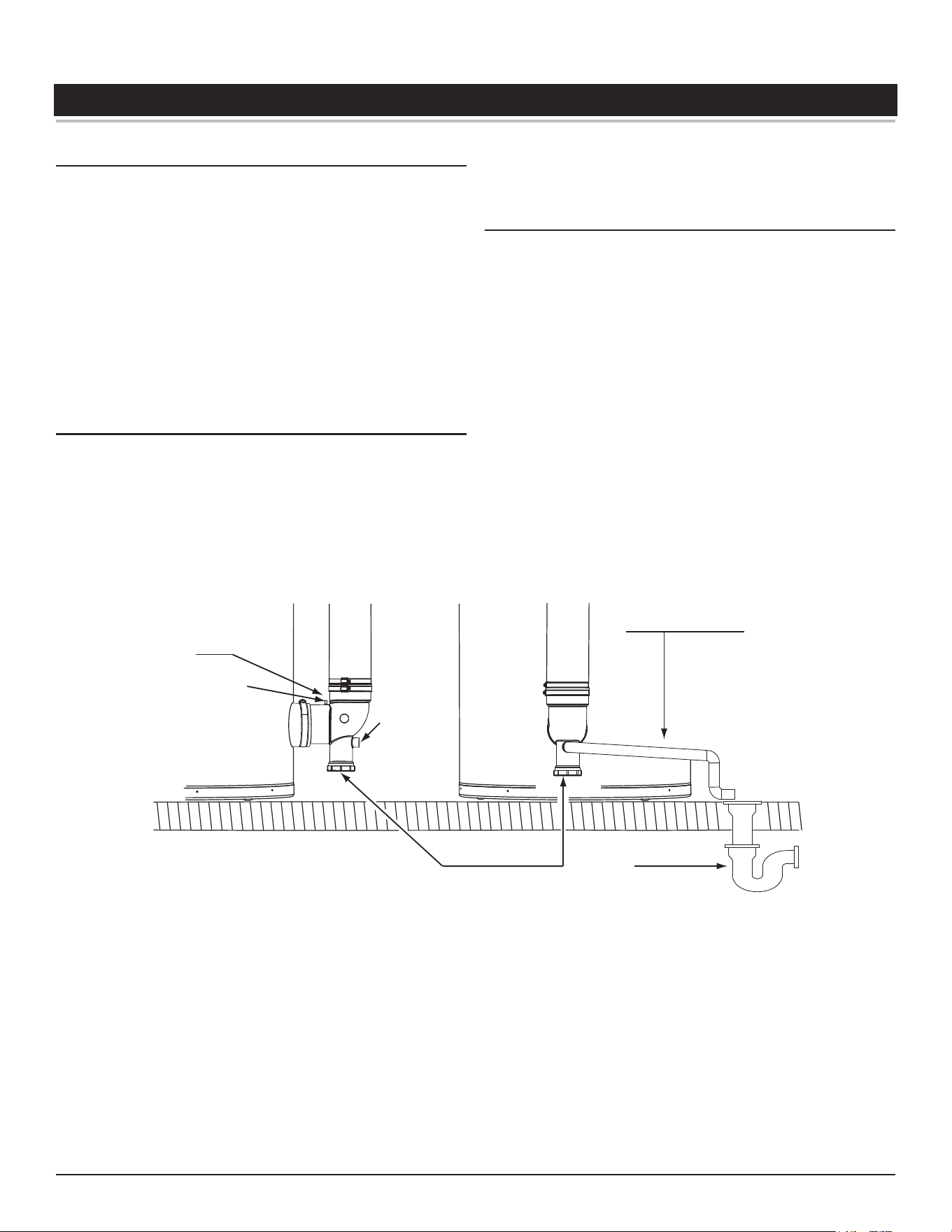
High-Eciency Commercial Gas Water Heaters • 49
WATER HEATER INSTALLATION
CONDENSATE DRAIN INSTALLATION
Installation must conform with these instructions and local building codes.
Field-supplied materials required for installation include:
• Approved PVC cement and PVC primer.
• 1/2 inch PVC pipe - minimum length to equal the distance between
the water heater and a suitable building drain.
• 1/2 inch PVC fittings (elbows, couplings, and adapters) necessary
to install a condensate drain line between the Exhaust/Condensate
Elbow Assembly and a suitable building drain.
• Floor mounted standoffs to brace the drain line.
Installation Notes
1. The condensate drains from the water heater’s covered by this
instruction have pH levels between 4.3 and 5.0. Install a commercially
available neutralizing kit if required by local codes. Lower PH levels are
acidic. Do not connect a metal condensate drain line, such as copper
pipe, to the water heater for this reason.
2. The field installed condensate drain line must not be less than 1/2
inch PVC in size.
3.
The exhaust elbow has a built in condensate trap. Do not install an
additional trap in the condensate drain piping. Do not
remove, modify
or alter the factory condensate trap.
Installation Instructions
1. Ensure the water heater’s Enable/Disable switch is in the “Disable”
position.
2. Install a 1/2 inch PVC condensate drain line between condensate drain
connection on the Exhaust/Condensate Elbow and a suitable building
drain. The condensate line must slope to an open drain, see
Figure 56
.
3. Terminate the condensate drain piping with an elbow above the drain.
Ensure that any discharge will exit the condensate drain line no more
than 6 inches (15.2 cm) above a suitable building drain, or external to
the building, see
Figure 56
.
Note:
In cold climates it is recommended the condensate drain be
terminated at a suitable drain inside the building.
4. Ensure the condensate drain line is not elevated above the condensate
drain connection on the Exhaust/Condensate Elbow, see
Figure 56
.
5. Brace the condensate drain line with floor-mounted standoffs every
three feet.
6. Ensure that the condensate drains freely during start up, see
Start Up
(page 55).
7. Condensate clean out cap must be on and tight when unit is in
operation.
CONDENSATE DRAIN
LINE - FIELD INSTALLED
BUILDING
DRAIN
1/2” NPT
CONDENSATE
DRAIN
CONNECTION
CONDENSATE
CLEANOUT
EXHAUST/CONDENSATE
(VENT) ELBOW
PRESSURE PORT
Figure 56. Condensate Drain Installation
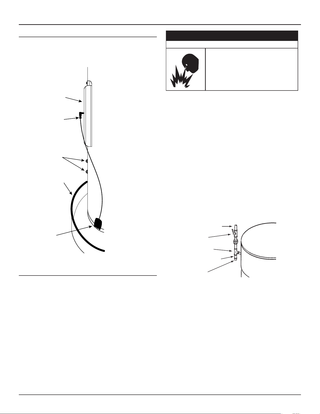
50 • High-Eciency Commercial Gas Water Heaters
Water Heater Installation
LEAK DETECTION MODULE INSTALLATION
The water heaters covered in this manual have a water leak protection
feature that senses the building of water in the vicinity of the appliance,
setting off alarm to alert the end user. Please follow installation instructions
in included kit.
Sensor
(Inside Drain Pan)
Drain Pan
Wire Mounts
Connector
Cleanout Cover
Access
Figure 57. Leak Detection Module Installation
SUPPLY GAS LINE INSTALLATION
Contact your local gas utility company to ensure that adequate gas service
is available and to review applicable installation codes for your area.
Be sure that the gas meter has sufficient capacity to supply the rated gas
input of the water heater as well as the requirements of all other gas fired
equipment supplied by the meter. If the gas meter is undersized, the gas
company will have to install a properly sized gas meter.
• Do not use water heater with any gas other than
the gas shown on the rating label.
• Excessive gas pressure to gas valve can cause
serious injury or death.
• Turn off gas lines during installation.
• Contact a qualified installer or service agency for
installation and service.
⚠
WARNING
Fire and Explosion Hazard
Make sure gas supplied is same type listed on the water heater’s rating
label.
The water heaters covered in this manual are not intended for operation
at higher than 14.0" W. C. (2.62 kPa) for natural gas and 14.0" W. C. (3.49
kPa) for propane gas supply pressure, see
Table 5
(page 17). The water
heaters covered in this manual require supply gas regulators to maintain
required supply gas pressure. Exposure to higher gas supply pressure may
cause damage to the gas controls which could result in fire or explosion. If
overpressure has occurred such as through improper testing of gas lines
or malfunction of the supply system the water heater’s gas valve must be
checked for safe operation by a Qualified Service Agency.
Ensure supply regulator vent lines and the safety vent valves are protected
against blockage. These are components of the gas supply system, not the
water heater. Vent blockage may occur during ice storms.
It is important to guard against gas valve fouling from contaminants in the
gas ways. Such fouling may cause improper operation, fire or explosion. If
copper supply lines are used they must be internally tinned and certified
for gas service.
REGULATED GAS
SUPPLY LINE
MAIN GAS
SHUTOFF VALVE
TEE FITTING
PIPE CAP
SEDIMENT TRAP
Figure 58. Supply Gas Line Installation
Ensure all gas pipe is clean on the inside before installation. To trap any dirt
or foreign material in the gas supply line a sediment trap must be installed
as shown in
Figure 58
. The sediment trap must be readily accessible
and not subject to freezing conditions. Install in accordance with the
recommendations of the local gas utility company.
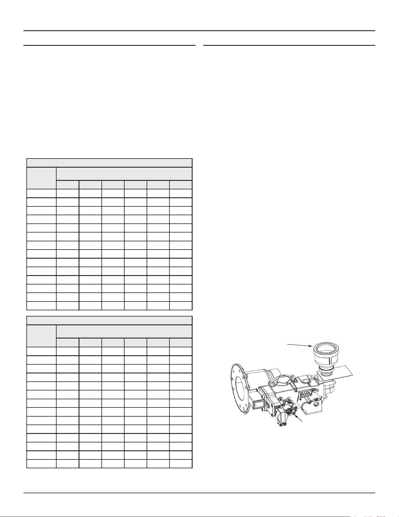
Water Heater Installation
High-Eciency Commercial Gas Water Heaters • 51
Gas Line Sizing
Depending on the developed equivalent length and/or the number of
appliances connected to a common main, the size of supply gas lines may
have to be increased.
Size the supply/main gas line(s) in accordance with
Table 16
or
Table 17
.
The values given in
Table 16
and
Table 17
are for straight lengths of iron
pipe at 0.5" W. C. (125 Pa) pressure drop, which is considered normal for
low pressure systems. Note that fittings such as elbows and tees will add
to the pipe pressure drop.
Schedule-40 Steel or wrought-iron pipe is the preferred material for
the gas line of this water heater. It is imperative to follow the sizing
recommendations in the latest version of the
National Fuel Gas Code
if
corrugated stainless steel tubing (CSST) is used as the gas line for this
water heater.
Table 16. Supply Gas Line Sizing U. S. Units
Length in
Feet
Normal Iron Pipe Sizes (Inches)
Input In Thousands Btu/Hr
1/2” 3/4” 1” 1 1/4” 1 1/2” 2”
10 175 360 680 1400 2100 3960
20 120 250 485 950 1460 2750
30 97 200 375 770 1180 2200
40 82 170 320 660 990 1900
50 73 151 285 580 900 1680
60 66 138 260 530 810 1520
70 61 125 240 490 750 1400
80 57 118 220 460 690 1300
90 53 110 205 430 650 1220
100 50 103 195 400 620 1150
125 44 93 175 360 550 1020
150 40 84 160 325 500 950
175 37 77 145 300 460 850
200 35 72 135 280 430 800
Table 17. Supply Gas Line Sizing Metric Units
Length In
Meters
Normal Iron Pipe Sizes (inches)
Input in kW
1/2” 3/4” 1” 1 1/4” 1 1/2” 2”
3.0 51 105 199 410 615 1160
6.1 35 73 142 278 428 805
9.1 28 59 110 225 346 644
12.2 24 50 94 193 290 556
15.2 21 44 83 170 264 492
18.3 19 40 76 155 237 445
21.3 18 37 70 143 220 410
24.4 17 35 64 135 202 381
27.4 16 32 60 126 190 357
30.5 15 30 57 117 182 337
38.1 13 27 51 105 161 299
45.7 12 25 47 95 146 278
53.3 11 23 42 88 135 249
61.0 10 21 40 82 126 234
Gas Line Connection
1. The 250 gallon water heaters are shipped from the factory with 3/4
inch supply gas connections. The supply gas line must not be smaller
than 3/4 inch. The 220 gallon units are shipped from the factory with
a 1 1/2" supply gas connection. The 499.9 KBTU natural gas models
require a 1 1/2" minimum supply gas line. All other 220 gallon units
require a 1 1/4" minimum supply gas line. Connect the supply gas line
to the water heater's gas valve in accordance with all applicable local
and national code requirements.
2. Depending on the developed equivalent length and/or the number of
appliances connected to a common main, the size of the supply gas
line may have to be increased. See
Gas Line Sizing
. If the supply gas
line must be resized larger to accommodate increased supply gas line
lengths or multiple appliances use reducer couplings and short pipe
nipples to increase the supply gas line.
Note:
Make the transition to the larger supply gas line as close to
the supply gas connection as possible.
3. Apply thread sealing compounds (pipe dope/thread-sealer tape)
sparingly and only to the male threads of the pipe joints. Do not apply
sealing compound to the first two threads. Use pipe dope or thread-
sealer tape marked as being resistant to the action of liquid petroleum
(LP/propane) gases.
4. Use only a smooth jaw adjustable wrench as a back up on the body of
the gas valve when tightening the first pipe nipple into the body of the
valve.
Do not
use a standard pipe wrench (Stillson wrench) with metal
tooth jaws as this may permanently damage the valve.
5. Use a standard pipe wrench (Stillson wrench) as a back up on the first
pipe nipple installed above when connecting other fittings and pipe in
the supply gas line to prevent the gas valve on the water heater from
twisting during installation.
6. To prevent damage, care must be taken not to apply too much torque
when connecting the supply gas line to the water heater.
7. Install a sediment trap as shown in
Figure 58
(page 50).
8. Install a Main Gas Shutoff valve in the supply gas line as shown in
Figure
58
(page 50).
Note:
If overheating occurs or the gas supply fails to shut off, turn
off the Main Gas Shutoff valve to the water heater.
9. Ensure gas line is properly supported to prevent damage to gas train.
Gas Connection
Manifold Gas Pressure
Test Port (Non Adjustable)
Figure 59. 220 Gallon - Supply Gas Line Connection
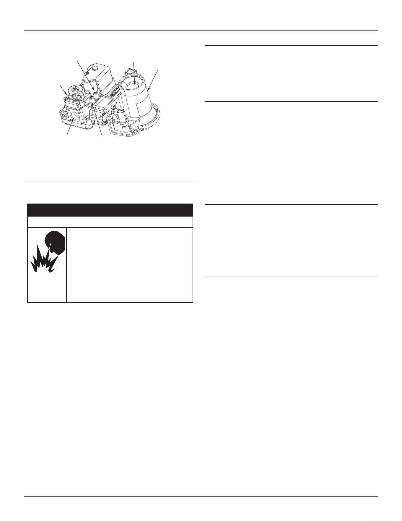
52 • High-Eciency Commercial Gas Water Heaters
Water Heater Installation
Gas
Valve
Supply Gas Pressure
Test Port
Gas
Connection
Venturi
Manifold Gas Pressure
Test Port (Non Adjustable)
Combustion Air Inlet
Figure 60. 250 Gallon VK - Supply Gas Line Connection
GAS LINE LEAK TESTING
Any time work is done on the gas supply system perform a leak test to
avoid the possibility of fire or explosion.
Gas piping can leak gas from fi�ngs and connec�ons if
it is not sealed properly. Gas leaks can cause fires and
explosions resul�ng in severe injury or death.
• Use joint compound or thread sealer tape compatible
with the type of gas you are using.
• Leak test all gas connections before placing the water
heater in operation.
• Disconnect gas piping at main gas shutoff valve before
leak testing.
• Install sediment trap in accordance with NFPA 54 or
CAN/CSA B149.1.
⚠
WARNING
Fire and Explosion Hazard
1. For test pressures exceeding 1/2 psi (3.45 kPa) disconnect the water
heater and its Main Gas Shutoff Valve from the gas supply piping system
during testing, see
Figure 58
(page 50). The gas supply line must be
capped when disconnected from the water heater.
2. For test pressures of 1/2 psi (3.45 kpa) or less, the water heater need
not be disconnected, but must be isolated from the supply gas line by
closing the Main Gas Shutoff Valve during testing.
3. Paint all supply gas line joints and connections upstream of the water
heater with a with a chloride-free liquid leak detection solution to test
for leaks. Bubbles indicate a gas leak. Do not use matches, candles,
flame or other sources of ignition for this purpose.
4. Repair any leaks before placing the water heater in operation.
Purging
Gas line purging is required with new piping or systems.
Purging should be performed per the current edition of
NFPA 54
the
National Fuel Gas Code
or
CAN/CSA B149.1
Natural Gas and Propane
Installation Code
.
ELECTRICAL WIRING
All electrical work must be installed in accordance with the
National
Electrical Code
,
ANSI/NFPA 70
or the
Canadian Electrical Code
,
CSA C22.1
and local requirements.
When installed, the water heater must be electrically grounded in
accordance with local codes or, in the absence of local codes, with the
National Electrical Code
,
ANSI/NFPA 70
or the
Canadian Electrical Code
,
CSA
C22.1.
If any of the original wire as supplied with the water heater must be
replaced, it must be replaced with 105°C rated wiring or its equivalent,
except in the burner housing. In this case 200°C rated wire must be used.
Dedicated Power Wiring and Breakers
Dedicated power supply wires, neutral wires, ground wiring, and dedicated
circuit breakers often prevent electrical line noise and are required when
installing the water heater.
Note: This water heater should not be connected to an electrical supply
with a Ground Fault Circuit Interrupter (GFCI) or Arc Fault Circuit
Interrupter (AFCI) with Integral GFCI protection as defined in
NFPA
70
,
CSA C22.1
and
UL 943
.
Power Supply Connections
Read the requirements for the
Power Supply
(page 20)
before connecting
power.
The 120-VAC hot wire from the power supply must connect to the black
jumper wire or the "L1" terminal block location in the junction box and
the 120-VAC neutral wire must connect to the white jumper wire or the
"Neutral" terminal block location in the junction box for correct polarity.
See
Figure 61
and
Figure 62
.
Power supply connections must be made as follows:
1. Turn off power at the water heater's enable/disable switch and the
breaker that supplies power to the water heater.
2. Remove the junction box cover. See
Figure 4
(page 12)
for junction
box location.
3. Connect the 120-VAC hot wire from the power supply to the black
jumper wire or the terminal block location marked "L1" inside of the
junction box located on top of the water heater. If the black jumper
wire is used, make the connection inside of the junction box with a
properly-sized wire nut. Wrap electrical tape around the wire nut and
wire end. See junction box
Figure 61
and
Figure 62
and the wiring
diagram
Wiring Diagrams
(page 100).
Note:
If electrical connection is made directly to terminal block
remove black jumper wire before making connection.
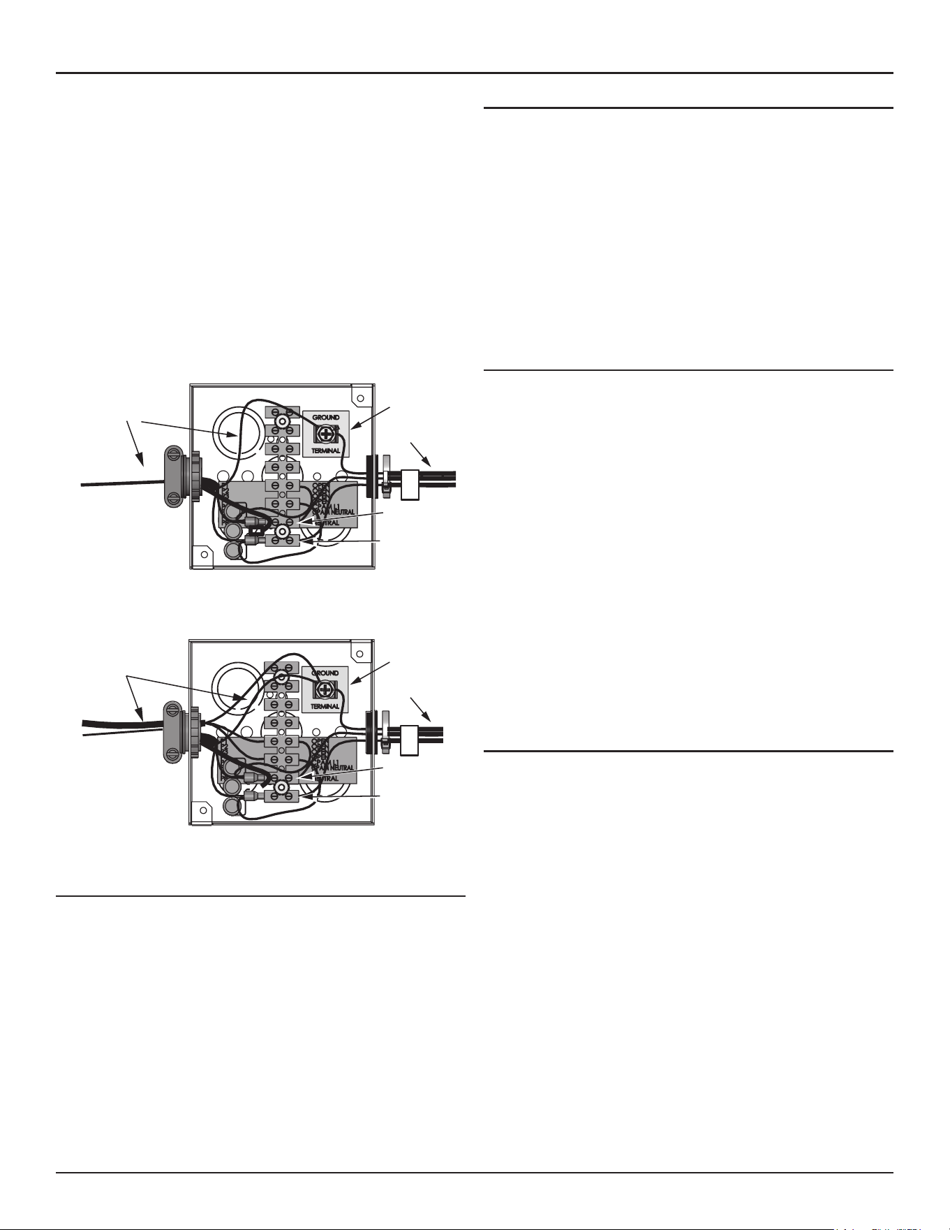
Water Heater Installation
High-Eciency Commercial Gas Water Heaters • 53
4. Connect the 120-VAC neutral wire from the power supply to the white
jumper wire or the terminal block location marked "Neutral" inside of
the junction box located on top of the water heater. If the white jumper
wire is used, make the connection inside of the junction box with a
properly sized wire nut and wrap electrical tape around the wire nut
and wire end. See junction box
Figure 61
and
Figure 62
and the wiring
diagram
Wiring Diagrams
(page 100)
Note:
If electrical connection is made directly to terminal
block, remove the white jumper wire before making the
connection.
5. Connect the ground wire from the power supply to the grounding lug
inside the junction box. See junction box
Figure 61
and
Figure 62
and
the wiring diagram
Wiring Diagrams
(page 100).
6. Replace junction box cover when connections are complete.
Note:
Do not apply power to the water heater before installation is
complete and the water heater is filled with water.
Ground
Terminal
Jumper Wire
Heater Wiring
(Factory Installed)
L1
Neutral
Figure 61. Junction Box (250 Gallon Models)
Ground
Terminal
Jumper Wire
Heater Wiring
(Factory Installed)
L1
Neutral
Figure 62. Junction Box (220 Gallon Models)
External Enable-Disable Circuit
The water heaters covered in this manual are equipped with an enable
disable circuit for use with field-supplied supervisory controls such as time
clocks or Building Management Systems. The enable/disable circuit may
be used to disable heating operation during periods when the building is
unoccupied or there is no demand for hot water. To use the enable disable
circuit it must first be activated by selecting “use External Enable” from
the UIM. Field support wiring is then installed between the water heater’s
controls and a set of dry contacts (no voltage or load) on the field-supplied
external control. See the wiring diagram,
Figure 74
(page 101) .
Water Line Connections
The water piping installation must conform to these instructions and to
all local and national code authority having jurisdiction. Good practice
requires that all heavy piping be supported.
Read and observe all requirements in the following sections before
installation of the water piping begins:
1.
Mixing Valves
(page 21).
2.
Dish-washing Machines
(page 21).
3.
Temperature-Pressure Relief Valve
(page 15).
4.
Closed Water Systems
(page 21) and
Thermal Expansion
(page 22).
5. For multiple water heater installations see
Piping Diagrams
(page 102).
Water Piping Diagrams
This manual provides detailed water piping diagrams for typical methods
of application for the water heaters. See
Piping Diagrams
(page 102).
The water heater may be installed with or without a separate storage tank.
When used with a separate storage tank, the circulation may be either
by gravity or by means of a circulating pump. When a circulating pump is
used, it is important to note that the flow rate should be slow so that there
will be a minimum of turbulence inside the water heater storage tank.
Adjust flow by throttling a full port ball valve installed in the circulating line
on the outlet side of the pump. Never throttle flow on the suction side of
a pump. See
Piping Diagrams
(page 102).
Note: In addition to the factory-installed Temperature-Pressure Relief
valve (T&P valve) on the water heater, each remote storage tank
that may be installed and piped to a water heating appliance must
also have its own properly sized, rated and approved Temperature-
Pressure Relief valve installed.
Call the toll free technical support phone number listed on the service parts
list for further assistance in sizing a T&P valve for remote storage tanks.
Thermometers (not Supplied)
Thermometers are installed in the water piping system as a means of
detecting the temperature of the hot water supply at critical points in the
system. Field-supplied thermometers should be obtained and installed.
See
Piping Diagrams
(page 102).
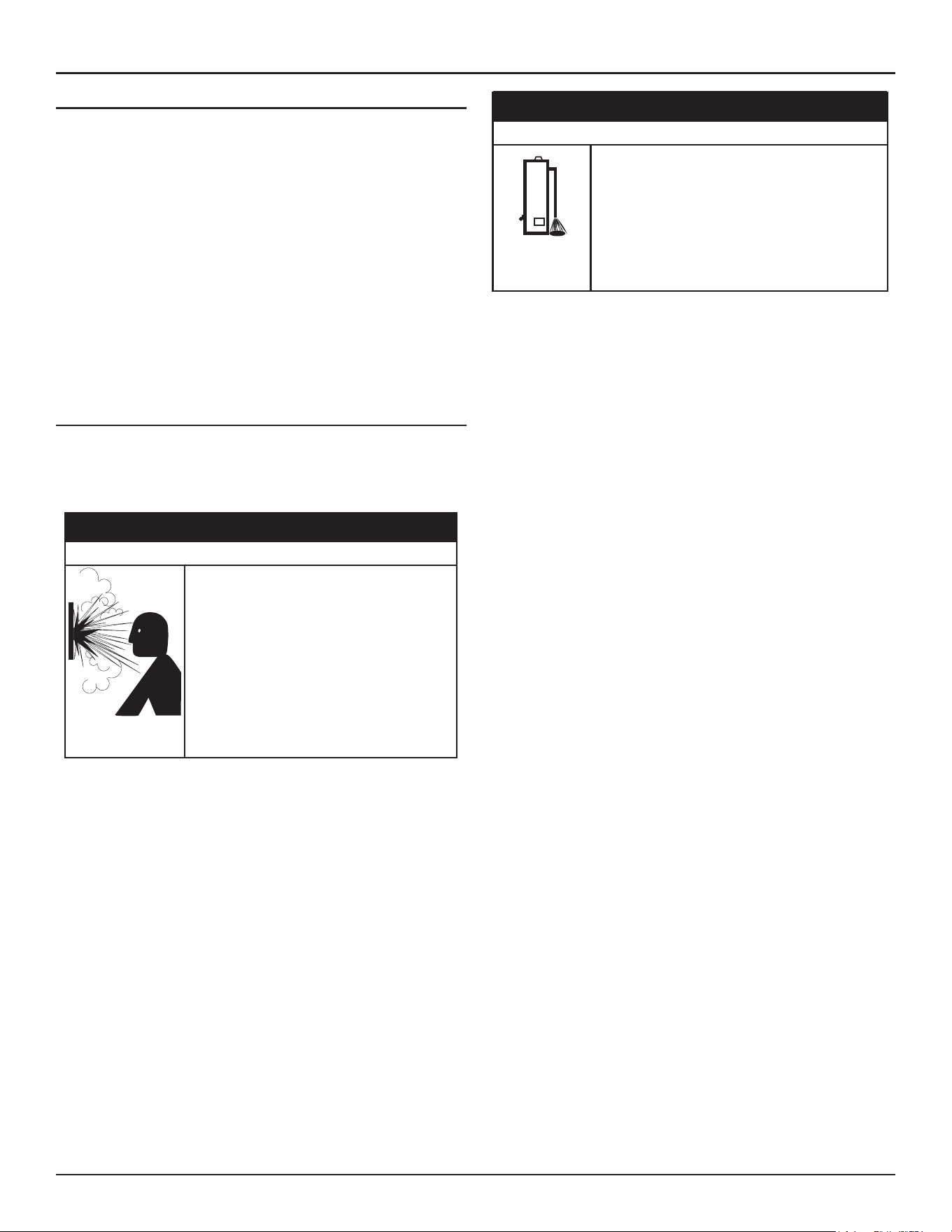
54 • High-Eciency Commercial Gas Water Heaters
Water Heater Installation
Water (potable) Heating And Space Heating
1. All water piping components connected to the water heater that are for
space heating applications shall be suitable for use with potable water.
2. Toxic chemicals, such as those used for boiler treatment, must NEVER
be introduced into this system.
3. The water heaters covered in this manual may never be connected
to any existing heating system or component(s) previously used with
non-potable water heating appliance.
4. When the system requires water for space heating that exceed safe
temperatures at domestic water fixtures a mixing valve must be
installed. See
Mixing Valves
(page 21).
Note:
Malfunctions caused by the power supply and costs to
install power supply filters are not covered under the limited
warranty. See Commercial Water Heater Limited Warranty
Insert.
5. These water heaters cannot be used in space heating applications only.
T&P VALVE DISCHARGE PIPE
This water heater is provided with a properly rated/sized and certified
combination temperature - pressure (T&P) relief valve by the manufacturer.
See
Temperature-Pressure Relief Valve
(page 22)
for information on
replacement and other requirements.
Normal opera�on of the water heater can cause
it to become sufficiently over-heated and/or
over-pressurized that it can explode, resul�ng in
property damage, sever injury, or death.
To avoid this hazard, you must install a properly-
sized temperature-pressure relief valve in opening
provided.
• The temperature-pressure relief valve must
comply with ANSI Z21.22-CSA 4.4 and ASME
code.
• Do not plug, block, or cap the discharge line.
⚠
WARNING
Explosion Hazard
Property Damage Hazard
While the water heater is in rou�ne opera�on, it can
release hot water from the temperature-pressure relief
valve discharge pipe in quan��es that could cause
damage to the surroundings.
Locate the water heater near an adequate drain and
in an area where water from the temperature-pres-
sure relief valve discharge pipe will not result in
damage to the area or the lower floors of the
structure.
⚠
CAUTION
Install a discharge pipe between the T&P valve discharge opening and a
suitable floor drain. Do not connect discharge piping directly to the drain.
A six inch (15.2 cm) air gap must be provided between the discharge
pipe and the drain. To prevent bodily injury, hazard to life, or property
damage, the relief valve must be allowed to discharge water in adequate
quantities if circumstances demand. If the discharge pipe is not located
near an adequate drain or other suitable means, the water flow may cause
property damage.
T&P Valve Discharge Pipe Requirements
• Shall not be smaller in size than the outlet pipe size of the valve, or
have any reducing couplings or other restrictions.
• Shall not be plugged or blocked.
• Shall not be exposed to freezing temperatures.
• Shall be of material listed for hot water distribution.
• Shall be installed so as to allow complete drainage of both the
Temperature-Pressure Relief Valve and the discharge pipe.
• Must terminate six inches (15.2 cm) above a floor drain or external
to the building. In cold climates, it is recommended that the
discharge pipe be terminated at an adequate drain inside the
building.
• Shall not have any valve or other obstruction between the relief
valve and the drain.

High-Eciency Commercial Gas Water Heaters • 55
START UP
PRIOR TO START UP
Installation and start up of this water heater requires abilities and skills
equivalent to that of a licensed tradesman in the field involved, see
Qualifications
(page 8).
DO NOT USE THIS APPLIANCE IF ANY PART HAS BEEN EXPOSED TO FLOODING
OR WATER DAMAGE
. Immediately call a qualified service agency to inspect
the appliance and to make a determination on what steps should be taken
next. If the unit is exposed to the following, do not operate heater until all
corrective steps have been made by a qualified service agency.
1. External fire
2. Damage
3. Firing without water
Light the water heater in accordance with the Lighting and Operation
Instruction label on the water heater and in this manual
Lighting the Water
Heater
(page 58).
The water heaters covered by this manual are equipped with an electronic
control system, which automatically sequences the Combustion Blower,
pre- and post purging of the combustion chamber, the spark transformer,
the gas valve, Main Burner ignition, and flame sensing. The control system
will lock out after three unsuccessful ignition attempts. See
Control System
Operation
(page 63).
Start-Up Preparation
Before attempting start up, thoroughly study and familiarize yourself with
the exact
Sequence Of Operation
(page 83). Ensure the water heater is
properly grounded. Flame sensing requires an adequate earth ground. If
the water heater is not properly grounded it will cause ignition failure.
Be certain that the water heater is full of water, that air is purged from the
gas and water lines and that there are no leaks in the gas and water lines.
Ensure all inlet water valves are open.
Filling The Water Heater
Follow these steps to fill the water heater prior to start up.
1. Close the heater drain valve.
2. Open a nearby hot water faucet to permit air in system to escape.
3. Fully open the cold water inlet valve allowing the piping and water
heater to fill with water.
4. Close the hot water faucet opened in Step 2 as water starts to flow.
INITIAL START UP
Required Test Equipment
• One U-tube manometer, recommended ranges; 0-14” W.C. (0-3.5
kPa) and 0-35” W.C. (0-8.7 kPa) or pressure gauges.
• One digital manometer can be used in place of U-tube manometers
or pressure gauges. Recommended ranges; -14.00 to +14.00”
W.C. (0-3.5 kPa) resolution 0.01” W.C. and 0-35” W.C. (0-8.7 kPa)
resolution 0.10” W.C.
Note: All test equipment must be acclimated to ambient temperature
before calibration and use.
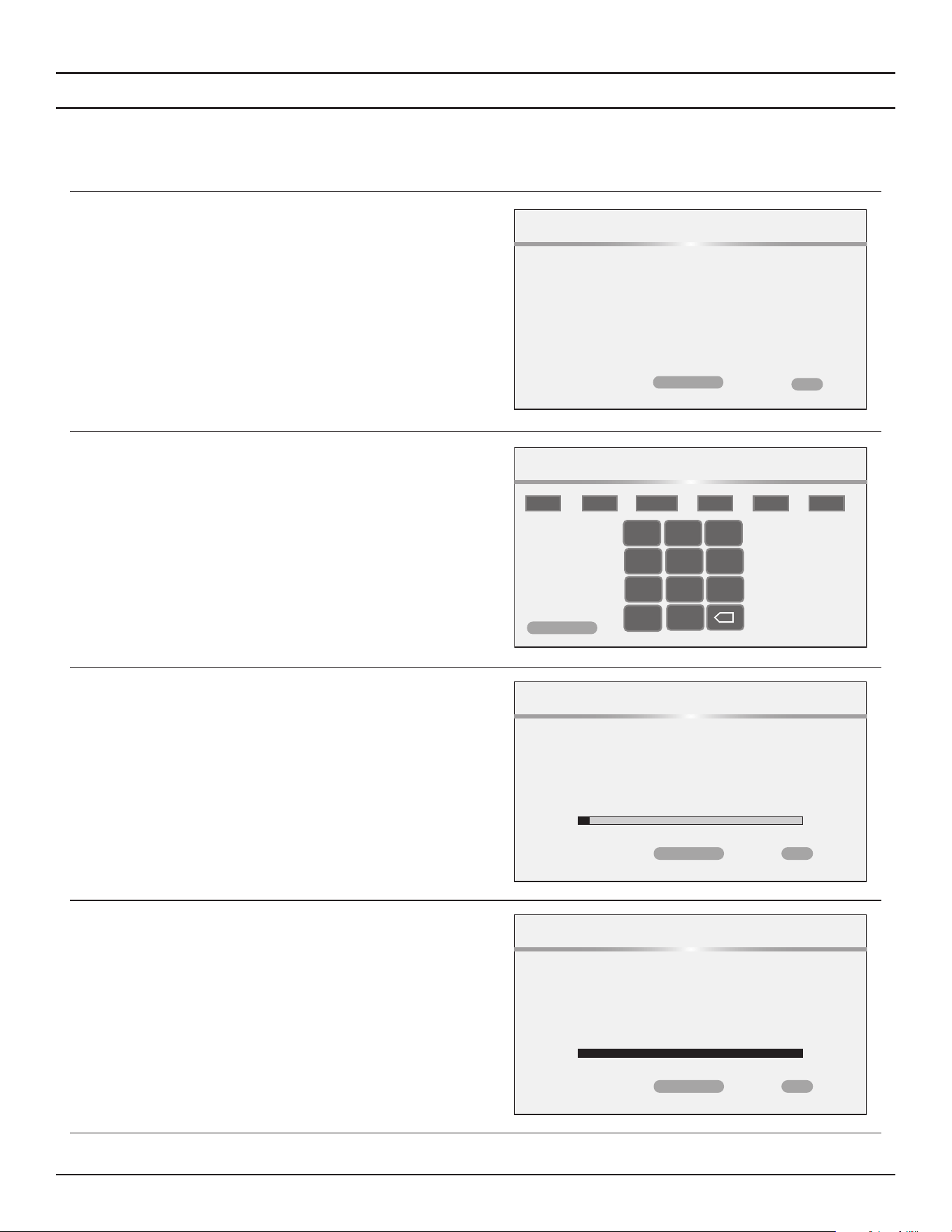
56 • High-Eciency Commercial Gas Water Heaters
Start Up
Gas Calibration
At the initial start up of the heater, an initial calibration routine must run.
This initial calibration may take up to 15 minutes.
During this initialization, any burner heat demand will be blocked.
After calibration, the continuous monitoring function becomes active.
This function can trigger a new calibration in case a gas quality change
is detected or there is a manual intervention by the qualified service
technician.
1. Click ‘Confirm’ to proceed with the calibration.
Please press confirm to start the calibration.
Calibration
CONFIRM
BACK
2. Set the date and time, then click Confirm to continue with the
calibration.
Calibration will begin and progress screen will display.
DATE/TIME
MONTH DAY YEAR HOURS MINUTES AM/PM
4
28
2025
/ /
12
53
PM
- :
1 2 3
TAB
4 5 6
7 8 9
0
CONFIRM
CANCEL
3. The calibration process will begin and show its progress on the screen.
Note:
Calibration may take up to 15 minutes.
When the calibration is complete, you will be returned to the home
screen
Calibrating
(May take up to 15 minutes)
Calibration
CONFIRM
BACK
4. When the calibration is complete, click BACK to return to the home
screen.
Calibration Complete
Calibration
CONFIRM
BACK
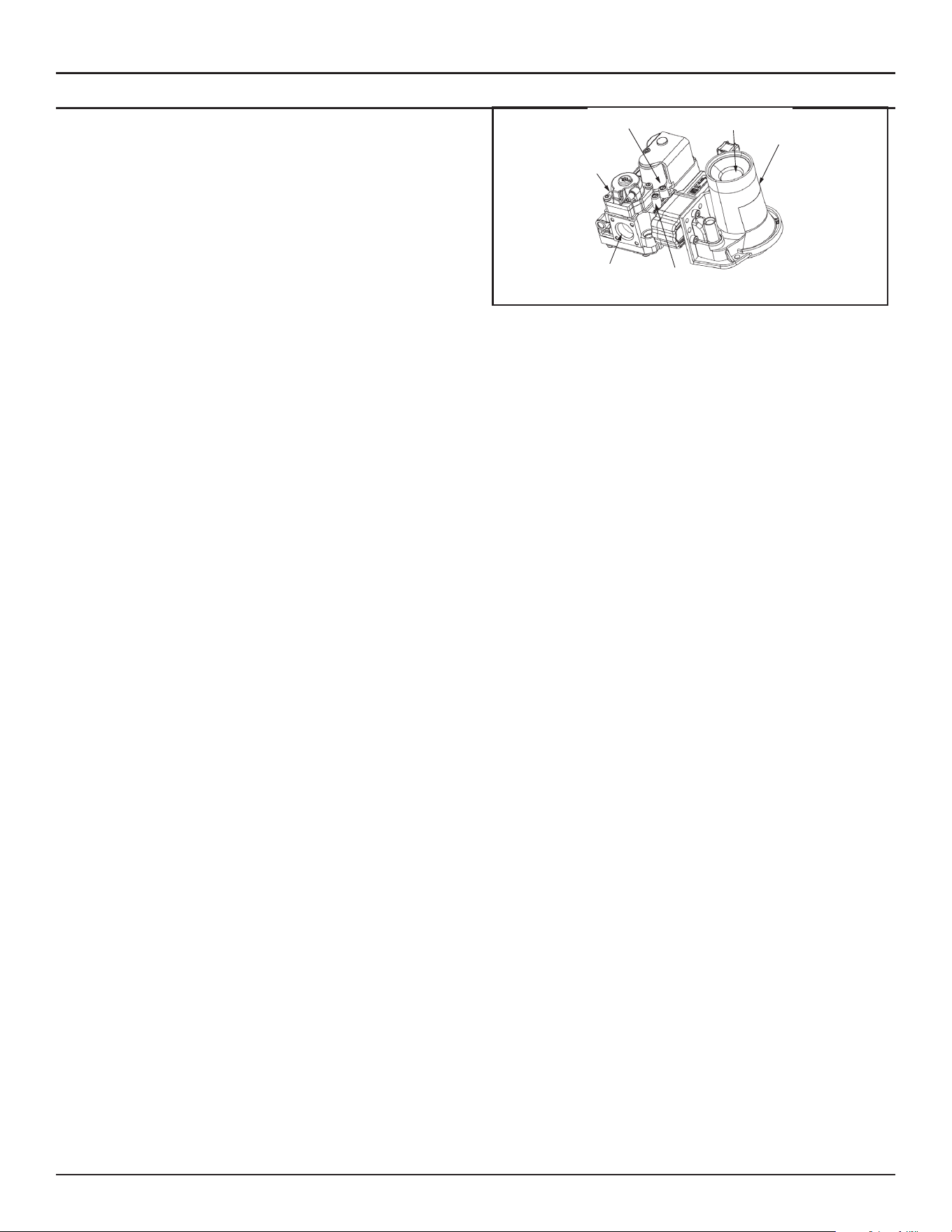
Start Up
High-Eciency Commercial Gas Water Heaters • 57
Start-Up Procedure
1. Using the control system menus, change the Operating Setpoint to the
lowest temperature setting. See
Operating Set-Point and Differential
Adjustment
(page 65).
2. Turn the water heater’s Enable/Disable switch to the "Disabled"
position.
3. Close the Main Gas Shut Off Valve, see
Figure 58
(page 50).
4. Wait five (5) minutes for any residual gas to clear.
5. Connect the manometer to the supply gas pressure port on the gas
valve. See
Figure 62
(page 53).
Note:
The manometer tubing should be purged before taking any
readings.
On the water heaters covered by this manual there are test ports for
supply and manifold gas pressure readings on the gas valve. Using a
small flat tip pocket screw driver - open the needle valve inside the
supply gas pressure test port one full turn only; turn the needle valve
screw counter-clockwise to open the valve. Slide the manometer
sensing tube over the top of the test port.
6. Open the Main Gas Shutoff Valve.
7. Measure and record the supply gas pressure, this is a “static” supply
gas pressure reading; while the water heater is not firing. Adjust supply
gas pressure as necessary.
Gas
Valve
Supply Gas Pressure
Test Port
Gas
Connection
Venturi
Manifold Gas Pressure
Test Port (Non Adjustable)
Combustion Air Inlet
Figure 63. Gas Valve Assembly
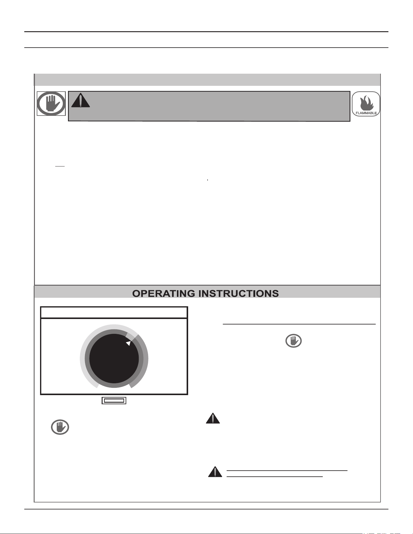
58 • High-Eciency Commercial Gas Water Heaters
Start Up
LIGHTING THE WATER HEATER
The instruction label below is affixed to the water heaters that are covered by this manual at the factory and must be followed when lighting and
operating the water heater.
FOR YOUR SAFETY READ BEFOR LIGHTING
WARNING: If you do not follow these instructions exactly, a fire or
explosion may result causing property damage, personal injury,
or loss of life.
BEFORE OPERATING: ENTIRE SYSTEM MUST BE FILLED
WITH WATER AND AIR PURGED FROM ALL LINES
This appliance does not have a pilot. It is equipped with
an ignition device which automatically lights the burner.
Do not try to light the burner by hand.
BEFORE OPERATING, smell all around the appliance
area for gas. Be sure to smell next to the floor because
gas is havier than air and will settle to the floor.
A.
B.
“WHAT TO DO IF YOU SMELL GAS”
• Do not try to light the appliance.
• Do no touch any electrical switch; do not use
any telephone in your building.
• Immediately call your gas supplier from a
neighbor’s phone. Follow the gas supplier’s
instructions.
• If you connot reach your gas supplier, call the
fire department.
Use only your hand to push in the control buttons.
Never use tools. If the control buttons will not push
in, don’t try to repair them, call a qualified service
technician. Force or attempted repair may result in
fire or explosion
C.
Do not use this appliance if any part has been under
water. Immediately contact a qualified installer or
service agency to replace a flooded water heater. Do
not attempt to repair the service unit. It must be
replaced.
D.
STANDBY-HOLD
SYSTEM OK
49°C
49°C
SETPOINT
ENABLE/DISABLE
SWITCH
STOP! Read the safety information above
on this label
Set the Enable/Disable switch on the control
panel to the Enable position.
1.
2.
Set the thermostat to the lowest setting.
3.
Set the Enable/Disable switch on the control
panel to the Disable position.
4.
This appliance is equipped with a device which
automatically lights the burner.
DO NOT TRY TO LIGHT THE BURNER BY HAND.
5.
Wait five (5) minutes to clear out any gas.
If you then smell gas, STOP! Follow “B” in the
safety information above on this label. If you don’t
smell gas, go to the next step.
6.
Turn on all electrical power to the appliance.
7.
Set the Enable/Disable switch on the control panel
to the Enable position.
8.
Set the thermostat to the desired setting.
9.
CAUTION: Hotter water increases the risk of
scald injury. Consult the instruction manual
before changing temperature
10.
If the appliance will not operate, follow the instruc-
tions “TO TURN OFF GAS TO APPLIANCE” and
call your technician or gas supplier.
WARNING: TURN OFF ALL ELECTRIC
POWER BEFORE SERVICING.
Set the thermostat to the lowest setting.
1.
Set the Enable/Disable switch on the control
panel to the Disable position.
2.
Turn off all electrical power to the appliance if
service is to be performed.
3.
TO TURN OFF GAS TO APPLIANCE
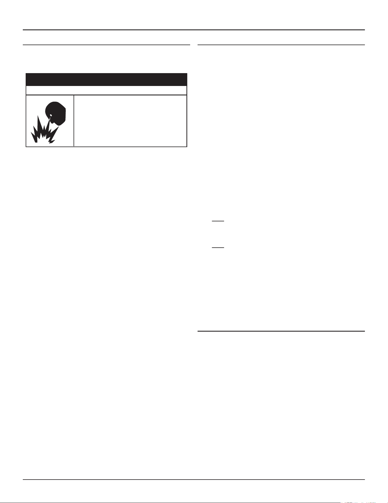
Start Up
High-Eciency Commercial Gas Water Heaters • 59
SUPPLY GAS PRESSURE ADJUSTMENT
Supply gas pressure shall be measured while the water heater is not
firing (static pressure) and while the water heater is firing at full capacity
(dynamic pressure).
• Do not use water heater with any gas other than
the gas shown on the rating label.
• Excessive gas pressure to gas valve can cause
serious injury or death.
• Turn off gas lines during installation.
• Contact a qualified installer or service agency for
installation and service.
⚠
WARNING
Fire and Explosion Hazard
If the supply gas pressure to the water heater is not between the required
minimum and maximum values given in
Table 5
(page 17)
adjust the
supply gas regulator as necessary. Adjust the supply gas regulator(s) per the
regulator manufacturer’s instructions to achieve the required “static” and
“dynamic” supply gas pressure. The dynamic pressure cannot be adjusted
directly but is directly proportional to the static pressure.
Multiple Water Heater Installations:
In multiple water heater installations or in installations where the installed
water heater(s) share a common gas supply main with other gas fired
appliances; the supply gas pressures shall be measured at each water
heater with all gas fired appliances connected to a common main firing
at full capacity.
On multiple water heater installations the supply gas line regulators shall
be adjusted to provide gas pressure to each water heater within the
minimum and maximum supply pressure requirements listed in
Table 5
(page 17)
with all gas fired appliances connected to a common gas
main firing at full capacity.
Note: A pressure drop of more than 1.5” W. C. (0.37 kPa) when the Main
Burner ignites is an indication of an inadequate supply of gas and
can lead to ignition failure, rough starts and/or rough operation. If a
drop of more than 1.5” W. C. (0.37 kPa) in supply gas pressure occurs
when the Main Burner ignites, ensure the supply gas lines and
regulator(s) are properly sized and installed. See the requirements
for
Supply Gas Regulator
and
Gas Supply Systems
(page 20). See
Supply Gas Line Installation
(page 50)
and
Supply Gas Regulator
(page 20). Ensure all requirements and installation instructions
are maintained.
CHECKING THE FIRING RATE
Follow these instructions to determine the actual firing rate of the water
heater:
Note: The heaters covered by this manual are capable of modulating
their firing rate. The firing rate should be checked with the heater
operating at it's full firing rate.
8. Ensure there are no other gas fired appliances connected to the gas
meter firing during this test.
9. Contact the gas supplier to determine the heating value, in Btu per
cubic foot, of the gas supply.
10. Connect a manometer to the supply gas pressure tap. Follow the
instructions for
Start Up
(page 55).
11. Start the water heater and ensure it is firing.
12. Check the supply gas pressure, refer to
Table 5
(page 17)
for correct
pressure.
13. Locate the gas meter serving the water heater.
14. Time how long (in seconds) it takes for one cubic foot of gas to be used
while the water heater is firing with a stop watch.
15. Use the formula below to “clock” the gas meter and determine the
actual firing rate of the water heater based on the heating value (Btu
per cubic foot) of the gas supply:
x H = Btu/hr
3600
T
x 1050 = 300,000 Btu/hr (87.9 kW)
3600
12.6
Example:
• 3600 = seconds in one hour.
• T = time, in seconds, to burn one cubic foot of gas.
• H = heating value of gas in Btu per cubic foot.
• Btu/hr = actual firing rate of the water heater.
Note:
1050 Btu per cubic foot is a standard value for natural gas.
Standard propane gas Btu content is 2500 Btu per cubic
foot. Btu values may change in certain areas and at high
elevations. Check with the local gas utility company.
To Turn Off Gas Supply
1. Change the Operating Setpoint to the lowest temperature setting, see
Operating Set-Point and Differential Adjustment
(page 65).
2. When the water heater has completed its shut down sequence and
enters the standby mode, turn the water heater’s Enable/Disable switch
to the “Disable” position. When in the "Disable" position the switch only
removes electrical power from the gas valve so that water heating is
disabled. The display, control boards, and other electrical components
will still be energized and the display will read "Water Heating Disabled".
3. Close Main Gas Shutoff Valve, see
Figure 58
(page 50).
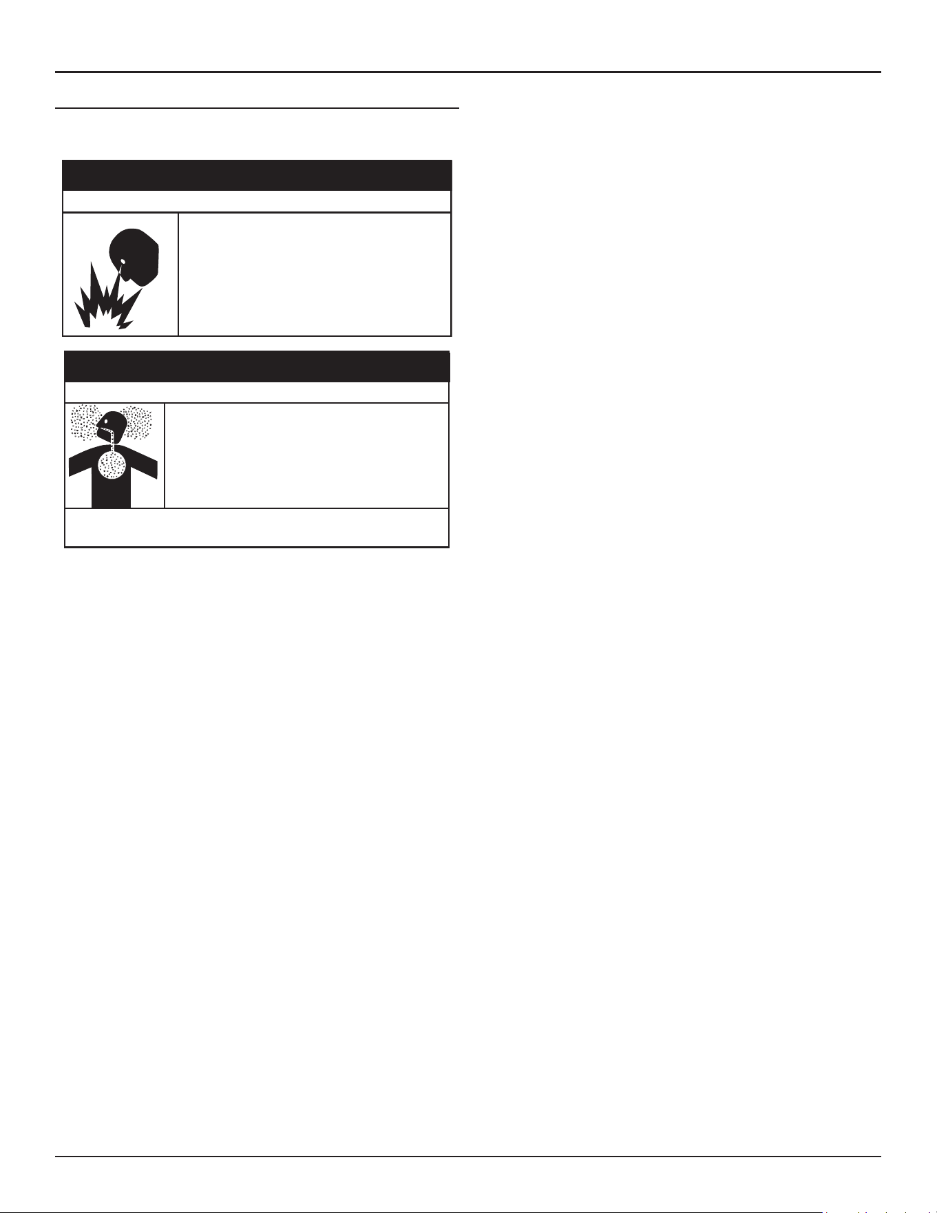
60 • High-Eciency Commercial Gas Water Heaters
Start Up
HIGH ALTITUDE INSTALLATIONS
The water heaters covered by this manual are certified for use without
modification for altitudes up to 10,100 feet (3,078 m).
Modifying the water heater to exceed the firing rate
on the ra�ng label can result in property damage,
personal injury or death.
• Under no circumstances should the input exceed
the rate shown on the water heater’s rating label.
• Over-firing could result in fire or explosion.
• Gas and carbon monoxide detectors are available.
⚠
WARNING
Fire and Explosion Hazard
• Under no circumstances should the input exceed
the rate shown on the water heater’s rating label.
• Overfiring could result in damage to the water
heater and sooting.
• Gas and carbon monoxide detectors are available.
Breathing carbon monoxide can cause brain damage or death. Always
read and understand instruc�on manual.
⚠
WARNING
Breathing Hazard - Carbon Monoxide Gas
Most gas utility companies derate their gas for high altitudes.
Note: The actual firing rate of the water heater must not exceed the input
rating on the water heater's rating label under any circumstances.
Note: Due to the input rating reduction at high altitudes, the output rating
of the water heater is also reduced and should be compensated
for in the sizing of the equipment.
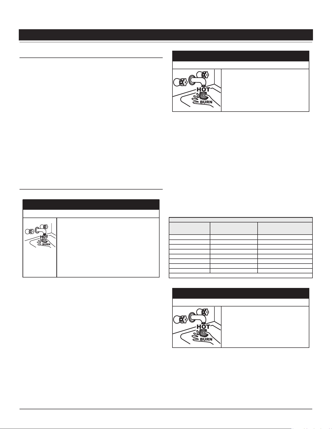
High-Eciency Commercial Gas Water Heaters • 61
TEMPERATURE REGULATION
HIGH TEMPERATURE LIMIT CONTROL
This water heater is equipped with an ECO (energy cut out) non adjustable
high temperature limit control.
The ECO is located inside the Upper Temperature Probe. The ECO activates
when the water temperature reaches an unsafe level and deactivates when
the water temperature falls back to a safe level.
If the ECO activates due to abnormally high water temperatures in the
storage tank the control system will immediately deenergize the gas
valve and end the current heating cycle. The control system will "lock
out" disabling further heating operation. The control system will display
the "High Temp Limit Exceeded" Fault message on the LCD screen. It is
important that a Qualified Service Agent be contacted to determine the
reason for the ECO activation before resetting the ECO. Once the reason
has been determined and corrected the ECO can be reset as follows:
If the ECO activates, the water temperature must drop below 140°F (60°C)
before the control system can be reset. Once the water temperature has
cooled below this point the power supply to the water heater must be
turned off and on again to reset the control system.
THERMOSTAT CONTROL
Water temperature over 52°C (125°F) can cause severe
burns instantly resul�ng in severe injury or death.
Children, the elderly and the physically or mentally
disabled are at highest risk for scald injury.
Feel water before bathing or showering.
Temperature limi�ng devices such as thermosta�c
point-of-use mixing valves must be installed when
required by codes and to ensure safe temperatures at
fixtures.
⚠
DANGER
Burn Hazard
Hot water temperatures required for automatic dishwasher and laundry
use can cause scald burns resulting in serious personal injury and/or death.
Table 18
(page 61)
shows the approximate time-to-burn relationship for
normal adult skin.
The temperature at which injury occurs varies with the person’s age and
duration of exposure. The slower response time of children, the elderly
or disabled persons increases the hazards to them. If anyone using hot
water provided by the water heater being installed fits into one of these
groups or if there is a local code or state law requiring a certain water
temperature at the point of use, then special precautions must be taken.
The temperature of the water in the water
heater can exceed the thermostat se�ng and
be hot enough to cause burns.
If you choose a higher temperature se�ng,
install thermosta�c mixing valves at each
point-of-use to help avoid scalding.
⚠
WARNING
Burn Hazard
In addition to using the lowest possible temperature setting that satisfies
the demand of the application a means, such as a thermostatic point-of-use
mixing valve, for example, can be used at the hot water taps used by these
people to reduce the water temperature.
Check State and/or local codes for thermostatic point-of-use mixing valve
requirements and installation practices.
Never allow small children to use a hot water tap or draw their own bath
water. Never leave a child or disabled person unattended in a bathtub or
shower.
The water heater should be located in an area where the general public
does not have access to set temperatures.
Setting the Operating Setpoint at 120°F (49°C) will reduce the risk of scalds.
Some States require settings at specific lower temperatures.
Table 18. Burn Time at Various Temperatures
Water Temperature
°F (°C)
Time for 1st Degree Burn
(Less Severe Burns)
Time for Permanent Burns
2nd & 3rd Degree
(Most Severe Burns)
110 (43) (normal shower temp.)
116 (47) (pain threshold)
116 (47) 35 minutes 45 minutes
122 (50) 1 minute 5 minutes
131 (55) 5 seconds 25 seconds
140 (60) 2 seconds 5 seconds
149 (65) 1 second 2 seconds
154 (68) instantaneous 1 second
(U.S. Government Memorandum, C.P.S.C., Peter L. Armstrong, Sept. 15, 1978)
The temperature of the water in the water
heater can exceed the thermostat se�ng and
be hot enough to cause burns.
To reduce the risk of unusually hot water
reaching the fixtures in the house, install point
of use thermosta�c mixing valves at each point
of use.
⚠
WARNING
Burn Hazard
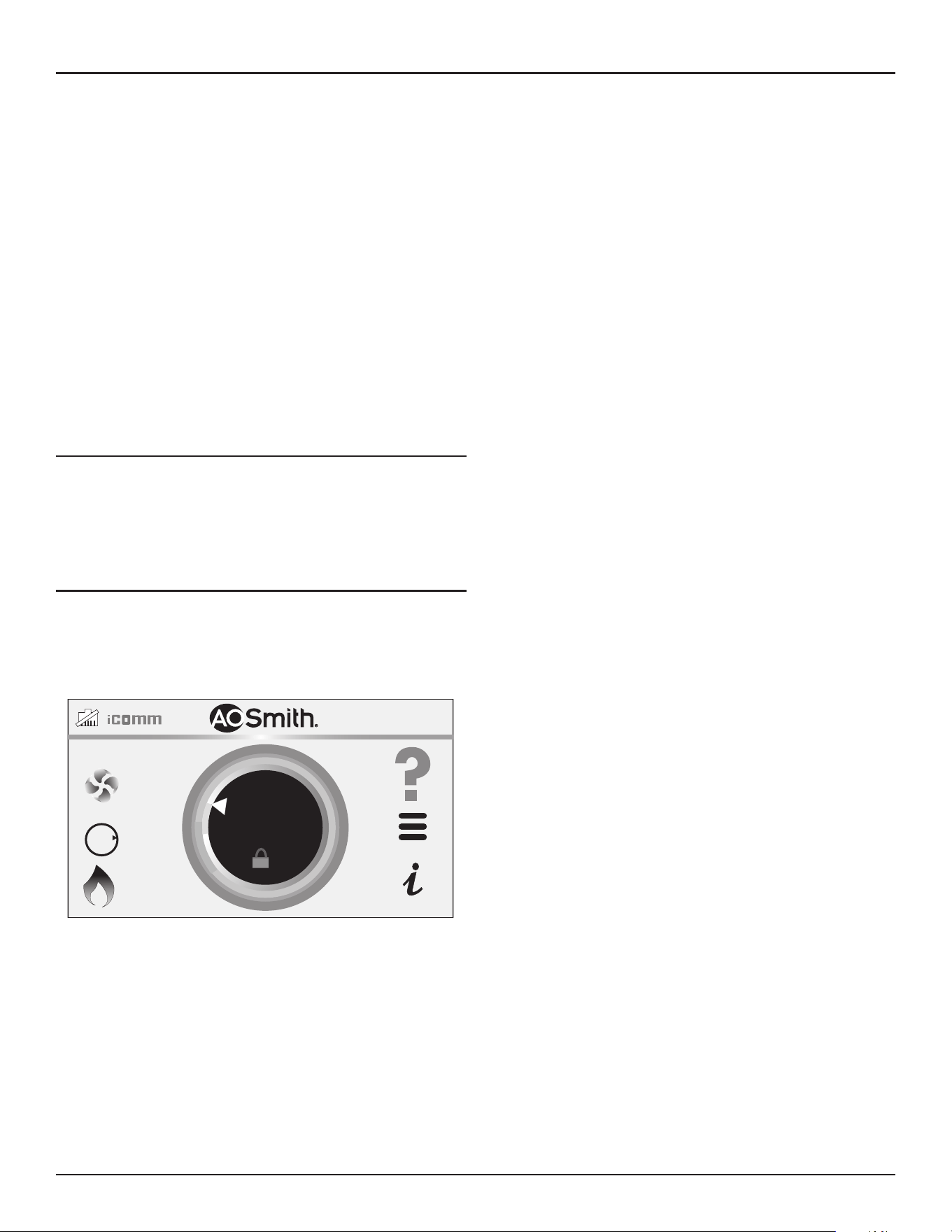
62 • High-Eciency Commercial Gas Water Heaters
Temperature Regulation
The water heaters covered in this manual are equipped with an electronic
control system to regulate water temperature inside the storage tank. The
control system senses temperature from two factory-installed temperature
probes, one installed in the top of the storage tank and one installed near
the bottom.
The “Operating Setpoint” is adjusted to regulate water temperature inside
the storage tank. This is an adjustable user setting in the control system’s
“Temperatures Menu.” This and all control system menus are accessed
through the UIM (user interface module) located on the front of the water
heater. See
Figure 66
(page 64).
The Operating Setpoint is adjustable from 90°F (32°C) to 180°F (82°C). The
factory setting is 120°F (49°C). See
Operating Set-Point and Differential
Adjustment
(page 65)
for instructions on how to adjust the Operating
Setpoint and other user settings.
Set the Operating Setpoint at the lowest setting that produces an
acceptable hot water supply. This will always provide the most energy
efficient operation.
FIRING RATE MODULATION
The water heaters covered by this manual are capable of modulating their
firing rate. The control boards monitor the water temperature in the tank
and regulates the firing rate to achieve the target temperature setpoint.
The firing rate is dictated by the hot water draw, proximity to the tank
temperature setpoint, and various other temperature limitations.
HIGH TEMPERATURE APPLICATIONS
Higher operating temperatures cause more wear on all water heaters
and will decrease the life span of the water heater. Consider installing
a small booster water heater for high temperature applications, such as
commercial dishwashers, to raise the outlet temperature from the larger
primary water heater to the desired point of use temperature.
BTH250-NAT
HEATING
118°F
120°F
OFF
GAS
O
N
SETPOINT
Figure 64. Tank Temperature Setpoint
Contact Technical Support for assistance. See the contact information
label on the water heater.
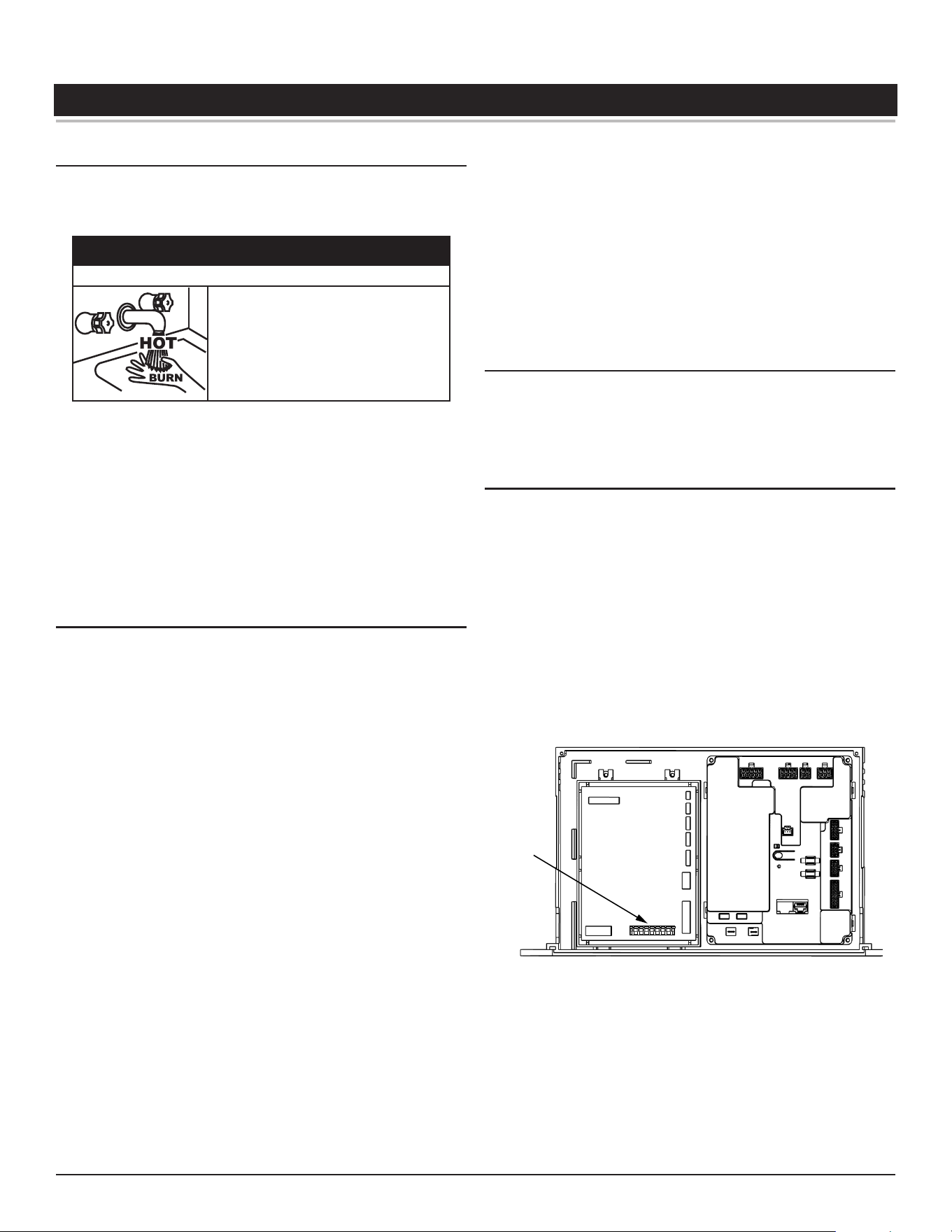
High-Eciency Commercial Gas Water Heaters • 63
CONTROL SYSTEM OPERATION
LIMITING THE RISK OF SCALDING
For a variety of reasons, water heaters can produce water that is much
hotter than its temperature setting. Take precautions to prevent this higher
temperature water from reaching the water fixtures.
The temperature of the water in the water
heater can exceed the thermostat se�ng and
be hot enough to cause burns.
To reduce the risk of unusually hot water
reaching the fixtures in the house, install point
of use thermosta�c mixing valves at each point
of use.
⚠
WARNING
Burn Hazard
According to a national standard,
Performance Requirements for Water
Temperature Limiting Devices (ASSE 1070)
and many local plumbing codes,
the water heater’s gas control valve should not be used as the sole means
to regulate water temperature and avoid scalds.
A properly adjusted thermostatic mixing valve at each point of use allows
you to set the tank temperature to a higher setting without increasing
risk of scalds. A higher temperature setting allows the tank to provide
much more hot water and can help provide proper water temperatures
for appliances such as dishwashers and washing machines.
WI-FI
The water heaters covered in this manual feature a Wi-Fi functionality
that is enabled at the factory. If Wi-Fi is not required for installation, you
can be disabled it as follows:
1. Go to main menu screen
2. Select iCOMM icon
3. Wi-Fi Status should show “AP Mode” (If not scroll down to “Change to
AP Mode” line item and Enable)
4. Enable the Wi-Fi if it is showing as disabled
5. Using a phone or tablet go to the Wi-Fi settings and search available
networks
6. In the list of networks, there should be a name that is similar to
“iCOMMNextGenUIM-XXXXXXXX”. This is the website being broadcast
by the display on the water heater. Select this network.
7. After selecting the iCOMM network, a separate message may appear
asking for permission to Stay Connected to the selected network.
Select the option to stay connected. Under the selected network
name, there should be an indication that the Wi-Fi connected with
the above iCOMM network.
8. Open a new Internet browser window on the device.
9. The Internet browser may automatically go to the web address
192.168.0.1. If it doesn’t, type that number into the address bar. This
will bring up a page that looks similar to the following:
10. Find the network name on the left that corresponds to the local Wi-Fi
network, and select the Connect button to the right of it.
11. If the local network is password protected, a new screen will appear
asking for the password. Enter the password for the local network and
click Connect.
12. A confirmation message should appear indicating the Connection to
Wi-Fi was completed.
LOCKOUT FUNCTION
The water heaters covered in this manual feature a lockout functionality
that is disabled at the factory by default. If the lockout functionality is
required by the end user, the initial installer/contractor can access this
functionality and enable it through the UIM.
CONTROL SYSTEM OVERVIEW
The water heaters covered in this manual are equipped with an electronic
control system that regulates water temperature inside the storage tank.
Heating cycles and ignition are managed by the control system. The ECO,
flame sensor, pressure switches, and temperature probes are monitored
by the control system. The combustion blower, spark ignition transformer,
gas valve and anode rods are all powered by the control system.
The main components of the control system are a user interface module
(UIM), Temperature Regulation Control (TRC) and control system circuit
(CSC). The UIM is located on the top front side of the water heater. The
control boards are mounted on top of the water heater inside a protective
enclosure. This unit is equipped with an Enable/Disable switch. To operate
unit, make sure the switch is set to Enable. See
Features and Components
(page 10) for location of these and all water heater components.
TRC
CSC
J13
Figure 65. Control System Components
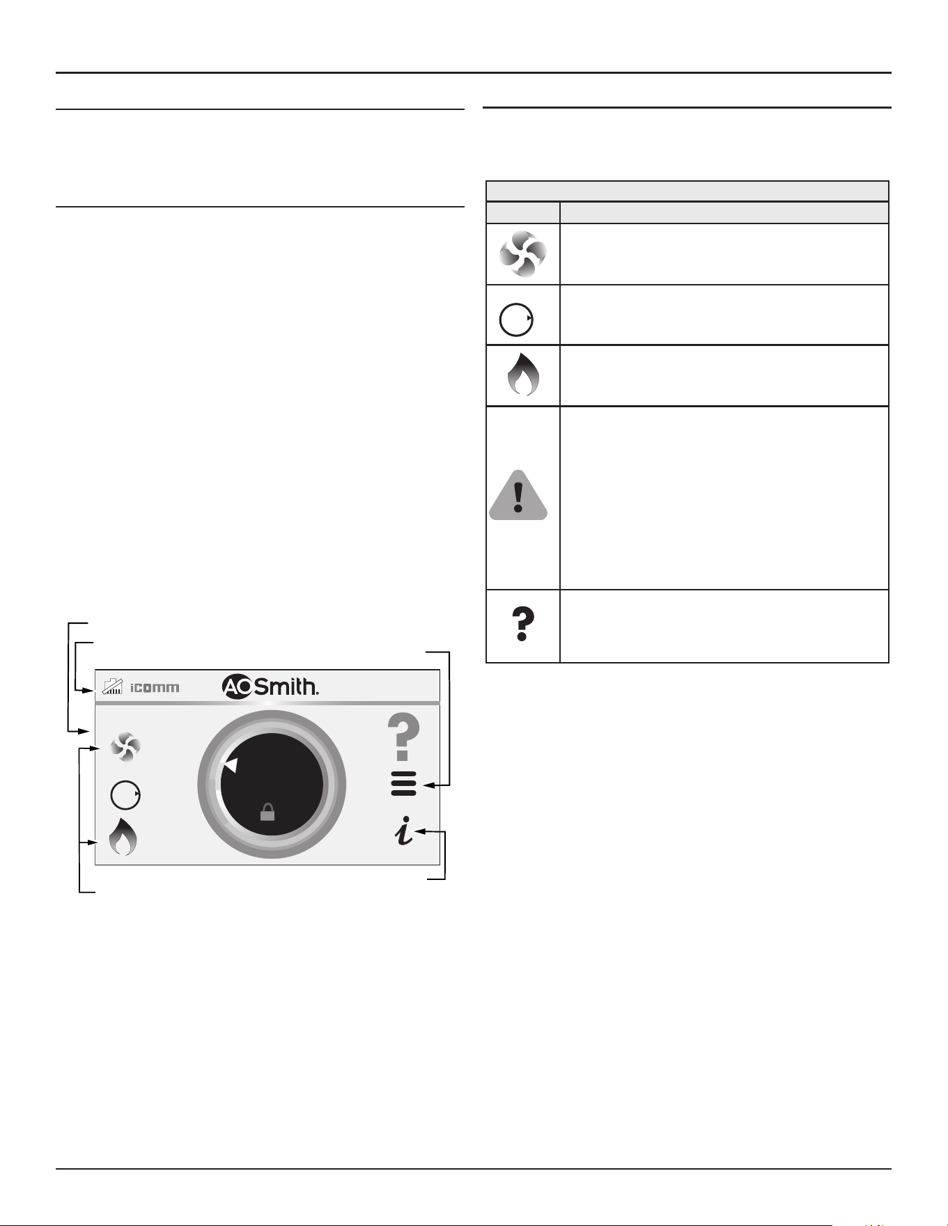
64 • High-Eciency Commercial Gas Water Heaters
Control System Operation
CONTROL SYSTEM NAVIGATION
All operational information and user settings are displayed and accessed
from the UIM. The UIM houses the control system's LCD Touch Display
(liquid crystal display).
The Home Screen
During normal operation, the control system displays the Home screen
on the LCD Touch Display, which is the default screen. The control system
returns to the Home screen when there are no active fault or alert
conditions or when there has been no user input for several minutes.
• Manufacturer and water heater model information displays in the
Title Bar at the top of the Home screen.
• The Operating setpoint is shown in the middle of the Home screen.
This is the temperature at which the control system will maintain
the water inside the storage tank.
• Status is shown in the upper left. The status shows the current
operational state of the control system in real time.
• The light green band on the temperature dial shows the
temperature offset.
• The three horizontal lines on the Home screen will allow you to
access sub menus.
• The Home screen also displays animated status icons to convey
operational information. See
Table 19
(page 64)
for descriptions of
the status icons.
HEATING
118°F
120°F
SET POINT
OFF
GAS
O
N
Touch Display
Status
Icons
Title Bar
Menu:
(Operational Menus
are Multifunctional.)
Help
Figure 66. User Interface Module (UIM) Home Screen
Status Icons
The Status Icons are displayed on the Desktop screen and convey
operational and diagnostic information. The icons are described in the
table below.
Table 19. Status Icons
Icon Description
The Combustion Blower is energized.
OFF
GAS
O
N
The gas valve is being energized.
The control system has sensed flame at the Main Burner
from the flame sensor. See
Sequence Of Operation
(page
83) and
Figure 2
(page 11).
The control system has declared a fault condition and
must be inspected/serviced by a Qualified Service Agent.
Fault message details can be viewed in the Current Fault
menu. Heating operation is disabled (lock out) until the
condition that caused the fault is corrected. Power to the
water heater must be cycled off and on at the breaker to
reset the control system.
Note: Cycling power will not reset the control system if
the condition that caused the fault has not been
corrected.
The control system has declared an alert condition and
must be inspected/serviced by a Qualified Service Agent.
The water heater will continue to operate during an alert
condition.
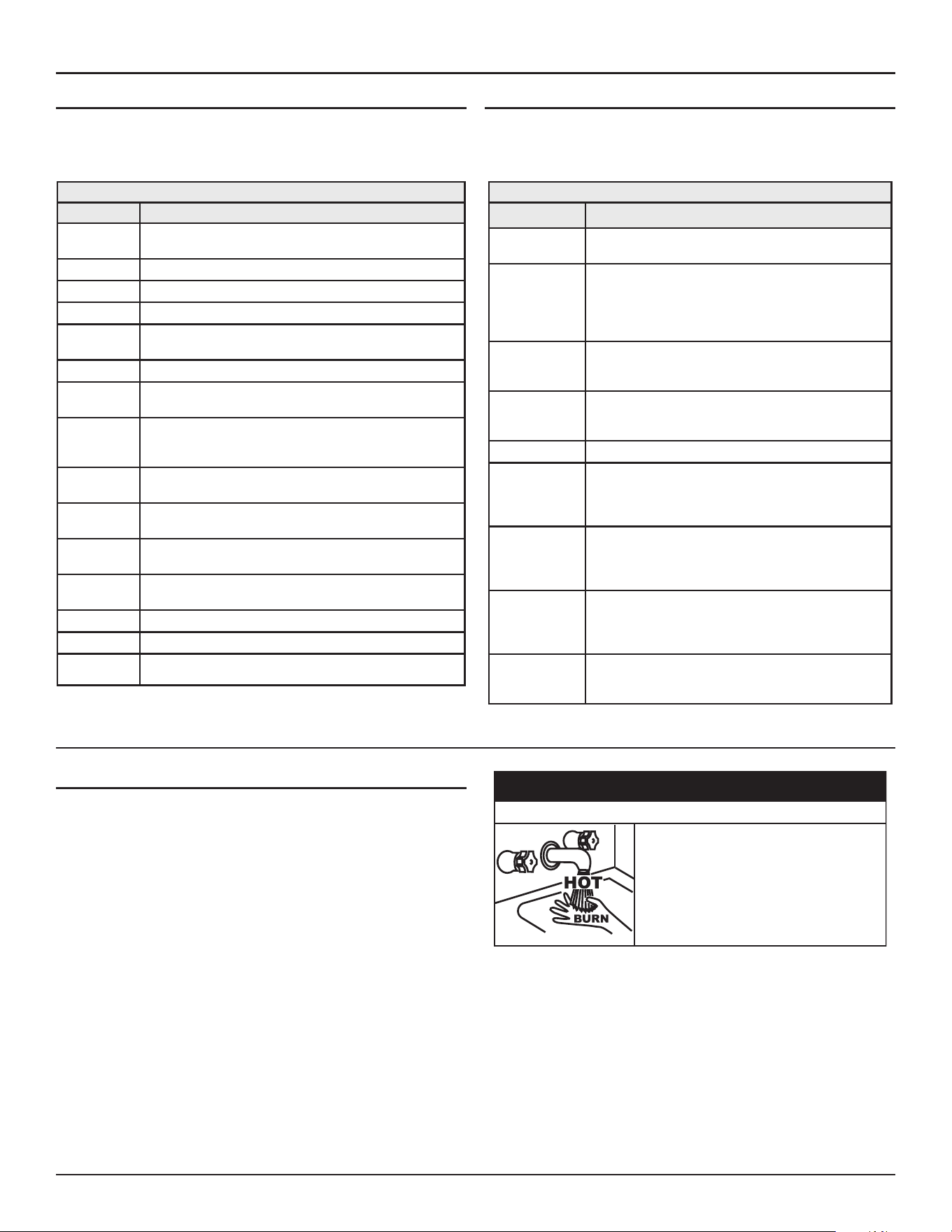
Control System Operation
High-Eciency Commercial Gas Water Heaters • 65
Operating States
The current operational state of the water heater is displayed on the Home
Screen as the "Status." The common operational states are described in
the table below.
Table 20. Operating States
State Description
Uncalibrated
The unit is currently uncalibrated and must go through cali-
bration before use.
Calibration
The unit is currently going through calibration procedure.
Standby
Heater is waiting on a call for heat.
Initializing
Initializing heater before regular heating.
Input
Verification
The unit has begun a burn cycle and is checking all safety
circuits.
Pre-Purge
The unit has begun a spark period to ignite the main burner.
Ignition
The unit has begun a burn cycle and is checking safety
circuits.
Inter-Purge
After a failure to ignite the burner, the control is attempting
to purge any excess gas from the heater exchanger before
another attempt to light.
Heating
The water heater has been properly lit, and the water in the
tank is being heated.
Post-Purge
Combustion products are being pushed out of the heater
exchanger after a successful heating cycle.
System in Fault
The water heater control has detected a fault. No further
heating of the water will be done until reset.
Blocked
A condition is preventing a burn cycle that must clear before
resuming water heating.
Ext Ena
External enable/disable switch is active on unit.
BMS
BMS is active on unit.
Heater Dis-
abled
The heater has been disabled and will not heat water.
Control System Menus
From the Home Screen pressing "Menu" on the LCD Touch Display will
display the "Main Menu" this is where all control system menus are located.
The table below describes the control system menus.
Table 21. Control System Menus
Menu Description
Setpoint Manager
Most commonly accessed menu. Contains the Operating
Setpoint and Differential user settings.
Heater Status
This menu displays the current state of all pressure
switches and the high temperature limit control sensors.
The on/off status of the Combustion Blower, gas valve,
igniter, flame sensor and other monitored water heater
components are displayed in this menu.
Display Settings
Temperature units (°F or °C), the LCD appearance (bright-
ness/contrast) and back-light delay user adjustable set-
tings are located in this menu.
Heater Informa-
tion
Elapsed time of operation, total heating cycle time, heat-
ing cycle count, heating on time along with UIM and con-
trol board software revisions can be viewed in this menu.
Current Fault
Displays any current alert or fault messages.
Fault History
This control system menu retains a list of the last nine (9)
fault and alert messages with a time stamp. The newest
event will replace the oldest. Faults will clear after 30
days.
Fault Occurrence
This control system menu retains a running total of how
many times each fault condition has occurred since the
water heater was first installed. The data does not clear
and cannot be reset.
Restore
This control system feature allows the user to restore con-
trol system user settings to their factory default settings.
Display Settings preferences ARE NOT changed when
factory defaults are restored.
Help Screens
Text based operational and user information explaining
how to change user settings, navigate the control system
menus and icon descriptions.
USER SETTINGS & CONTROL SYSTEM MENUS
Operating Set-Point and Differential Adjustment
The Operating Setpoint is adjustable from 90°F (42°C) to 180°F (82°C).
The factory setting is 120°F (49°C). The Differential is adjustable from 2°F
(1°C) to 20°F (11°C). The factory setting is 8°F (4°C). These user settings
are accessed from the Temperatures menu. The following instructions
will explain how to adjust these settings and navigate the control system
menus.
When the water temperature sensed by the control system from the two
(upper and lower) Temperature Probes reaches the Operating Setpoint the
control system will end the heating cycle. A heating cycle will be activated
again when the sensed water temperature drops below the Operating
Setpoint minus the Differential setting.
The temperature of the water in the water
heater can exceed the thermostat se�ng and
be hot enough to cause burns.
If you choose a higher temperature se�ng,
install thermosta�c mixing valves at each
point-of-use to help avoid scalding.
⚠
WARNING
Burn Hazard
Note: Lower Differential settings may cause excessive heating cycles
(short-cycling) which can cause premature failure of heater
components. Set the Differential at the highest setting which
produces an acceptable hot water supply. Set the Operating
Setpoint to the lowest setting which produces an acceptable hot
water supply for most efficient use.
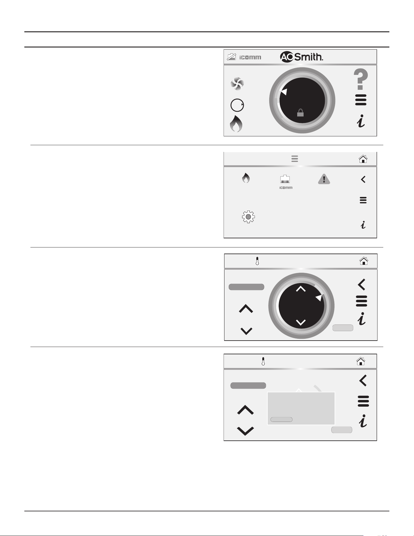
66 • High-Eciency Commercial Gas Water Heaters
Control System Operation
Setpoint Manager
From the Setpoint Manager, you can adjust the Differential Mode, the
Differential, and see the current Tank Temperature.
1. From the Home screen, press MENU icon. The “Main Menu” screen
will be displayed.
Note:
The differential is indicated by the light green band on the
temperature dial.
BTH250-NAT
HEATING
118°F
120°F
OFF
GAS
O
N
SETPOINT
The Main Menu is where all control system menus are listed. See
Table 21
(page 65) for a complete list and description of control
system menus.
2. Press Heater Menu to access the Setpoint Manager Menu.
FAULTS
SETTINGS
MAIN MENU
HEATER
3. Press Heater: Setpoint Manager to access the temperature setpoint
menu.
4. Use the arrow Buttons to change the current setting.
Note:
Higher Temperature settings increase wear and operating
costs. Set the Operating Setpoint to the lowest setting which
produces an acceptable hot water supply. This will always
provide the most energy efficient operation and longer life.
150°F
SETPOINT
SETPOINT MANAGER
MODE:
CANCEL
DIFFERENTIAL
10°F
ENTER
MANUAL
5. Tap “CONFIRM” to save the new setting. Press “CANCEL” to discard
changes and return to the previously saved setting.
150°F
SET POINT
SETPOINT MANAGER
MODE:
CANCEL
DIFFERENTIAL
10°F
ENTER
MANUAL
Setpoint changed:
New Setpoint is 130°F
Please confirm to continue:
CONFIRM CANCEL
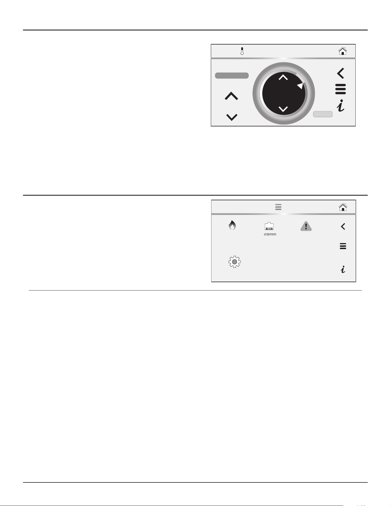
Control System Operation
High-Eciency Commercial Gas Water Heaters • 67
6. To change the differential setting: change the mode from automatic to
manual, then use the up and down arrows on the differential to change
setting. Confirm to keep changes or Press the Cancel button to return
to the previously saved settings.
•
Differential Mode
- Operating mode with an Intelligent Demand
Response (IDR). This mode allows the water heater to reduce
preset differential to a lower setting so that the appliance will
more rapidly respond to large draws to maintain water outlet
temperature. This mode is enabled at the factory by default, but
can be disabled in the field if required.
•
Differential
- Adjustable user setting that changes the tank
temperature differential with a range of 2° to 20°F. The factory
setting is 8°F.
•
Tank Temperature
- Non adjustable. Control system sensed
temperature (averaged from upper & lower temperature
probes).
These settings are adjusted in the same way described in
Operating Set-
Point and Differential Adjustment
(page 65).
150°F
SETPOINT
SETPOINT MANAGER
MODE:
CANCEL
DIFFERENTIAL
10°F
ENTER
MANUAL
iCOMM Menu
1. From the Home screen, press MENU icon.
The “Main Menu” screen will be displayed.
2. Press the iCOMM icon to access the iCOMM screen.
FAULTS
SETTINGS
MAIN MENU
HEATER
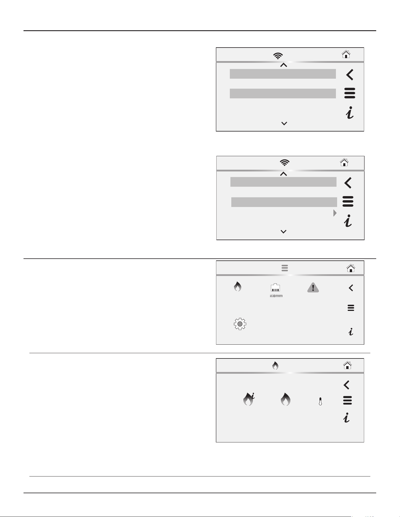
68 • High-Eciency Commercial Gas Water Heaters
Control System Operation
The iCOMM screen displays the following Wi-Fi information:
•
Wi-Fi Status
- displays status of Wi-Fi connection.
•
Ethernet
- displays status of Ethernet connection.
•
iCOMM Server
- displays status the iCOMM server.
•
Wi-Fi MAC
- displays the Wi-Fi MAC number.
•
Ethernet MAC
- displays the Ethernet MAC number.
•
DSN
- displays the Device Serial Number (DSN). Used for
registration of the heater.
•
Wi-Fi Strength
- displays Wi-Fi signal strength as a series of bars.
•
Wi-Fi Strength
- displays Wi-Fi signal strength dBm units.
Wi-Fi
- Wi-Fi functionality is enabled at the factory. In the bottom
portion of the menu, the Wi-Fi can be disabled by selecting the
Enabled>
marker and selecting the
Disable
option. This is the only
item on this screen that can be adjusted. The other items are for view
and information purposes only.
Top of Menu
iCOMM
Wi-Fi Status Connected
Ethernet Not Connected
Registration Registered
iCOMM Server Connected
Bottom of Menu
DSN
AC000W006323619
Wi-Fi Strength
0Bars
Enabled
Wi-Fi
-128dBm
Wi-Fi Strength
iCOMM
Heater Information Menu
1. From the Home screen, press MENU icon.
The “Main Menu” screen will be displayed.
2. From the Main Menu, press the Heater icon to access the Heater menu.
FAULTS
SETTINGS
MAIN MENU
HEATER
3. Press the Heater Information icon from the Heater menu to enter the
Heater Information screen.
HEATER
INFORMATION
HEATER
STATUS
SETPOINT
MANAGER
HEATER MENU
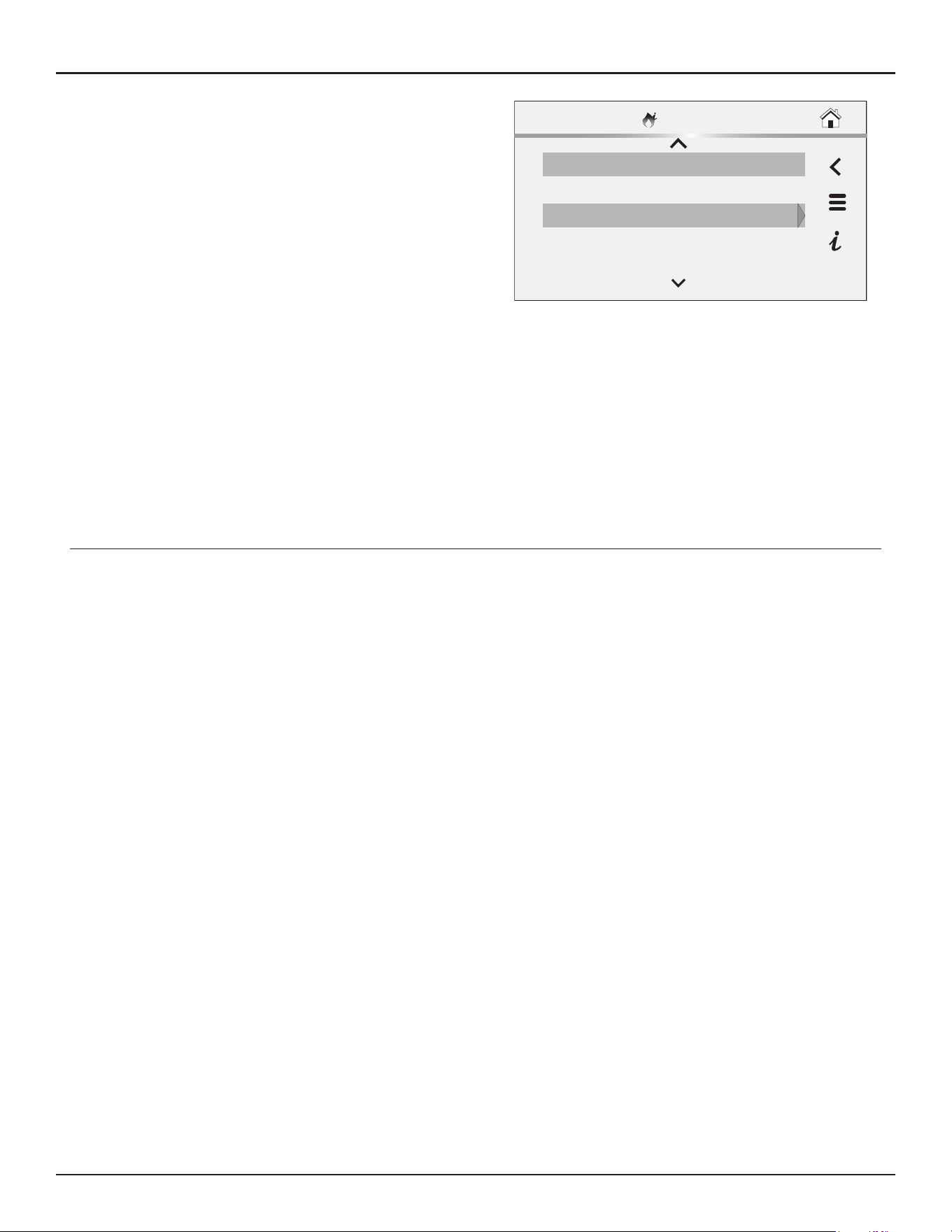
Control System Operation
High-Eciency Commercial Gas Water Heaters • 69
This screen contains non adjustable operational information.
•
Elapsed Time
- Total accumulated time the control system (water
heater) has been energized.
•
Total Heat Time
- Total accumulated time the control system has
been in the heating operating state; burner run time.
•
Total Cycle Counter
- Total accumulated count of heating cycles.
•
Ignition Failure Count
– Total accumulated count of ignition
failures.
•
Flame Loss Count
- Total accumulated count of flame losses.
•
TRC Version -
Software version for TRC board.
•
UIM Version
- Software version for user interface module.
•
Serial Number
- Serial number of the water heater.
•
Model Number
- Model number of the water heater
•
CSC Version
- Software version for CSC board.
•
CPAM1 Version
- Software version for CPAM1.
•
CPAM2 Version
- Software version for CPAM2.
•
Building Management Version
- Software version for Building
Management System.
•
Water Valve Control Version -
Software version for the water
valve control.
•
NANODE Version -
Software version for NANODE.
Elapsed Time 0 Days 0 Hrs 31 Mins 37
Total Heat Time
0 Days 0 Hrs 10 Mins 0 Secs
Yes
External Enable Status
YesUse External Enable
HEATER INFO
Historical data is stored in the FMM board. If this board is removed or
damaged during servicing the historical data will be lost and heater
will no longer operate. The FMM board should never be replaced
unless directed by Technical Support.
The Elapsed Time, Burner On Time and Cycle Count indicate age,
usage and wear.
If the Cycle Count per day is high (divide cycle count by days to
determine cycles per day) or the cycle duration is short (determine
burner on time total minutes, divide burner on time total minutes
by cycle count) consider raising the Differential setting to avoid short
cycling and excessive component wear. See
Operating Set-Point and
Differential Adjustment
(page 65).
This historical data can also be used to assist facilities managers in
forecasting planned replacement of equipment to help avoid lengthy
and costly hot water supply interruptions.
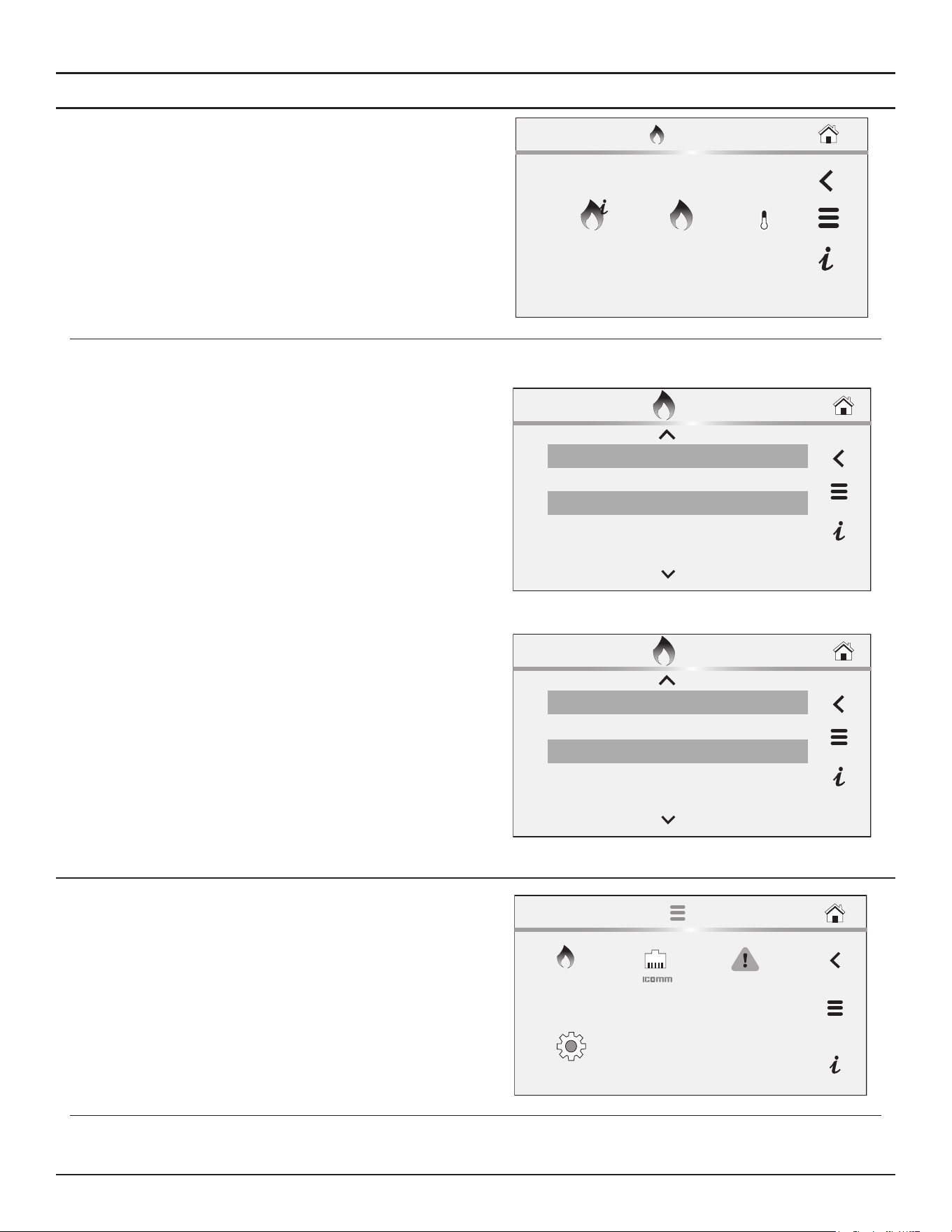
70 • High-Eciency Commercial Gas Water Heaters
Control System Operation
Heater Status Menu
1. From the Home screen, press MENU icon.
The “Main Menu” screen will be displayed.
2. From the Main Menu, press
Heater: Heater Information
to access the
Heater Information screen.
HEATER
INFORMATION
HEATER
STATUS
SETPOINT
MANAGER
HEATER MENU
The Heater Status menu displays the following information:
•
Status
- Indicates whether the heater is Enabled or Disabled.
•
Blocked Inlet PS
- Indicates if the Inlet is blocked.
•
Blocked Outlet PS
- Indicates if the Outlet is blocked.
•
Igniter On
- Indicates if the Igniter is operational
•
Gas Valve On
- Indicates if the gas valve is on.
•
Flame Detected
- Indicates if flame is detected.
•
Blower RPM
- Indicates the blower RPMs
•
Main Temperature
- Temperature reading of the main
temperature probe.
•
Lower Temperature
- Temperature reading of the lower
temperature probe.
•
Anode Current
– Current reading of anode
•
Anode Tank Voltage
– Voltage of anode tank
•
Anode Drive Voltage
– Voltage of anode drive
•
Water Valve 1 Status
– Current status of Water Valve 1
•
Water Valve 1 Error
– Error in Water Valve 1
•
Water Valve 2 Status
- Current status of Water Valve 2
•
Water Valve 2 Error
- Error in Water Valve 2
•
Water Valve 3 Status
- Current status of Water Valve 3
•
Water Valve 3 Error
- Error in Water Valve 3
Top of Menu
HEATER STATUS
Status: HEATER DISABLED
Blocked Inlet PS Open
Blocked Outlet PS Open
Igniter Yes
Bottom of Menu
HEATER STATUS
Water Valve 2 Status Yes
Water Valve 2 Error 3 Tries
Water Valve 3 Error 15rpm
Water Valve 3 Status 500rpm
Display Settings Menu
1. From the Home screen, press MENU icon.
The “Main Menu” screen will be displayed.
2. From the Main Menu, press the Settings icon to access the Settings
screen.
FAULTS
SETTINGS
MAIN MENU
HEATER
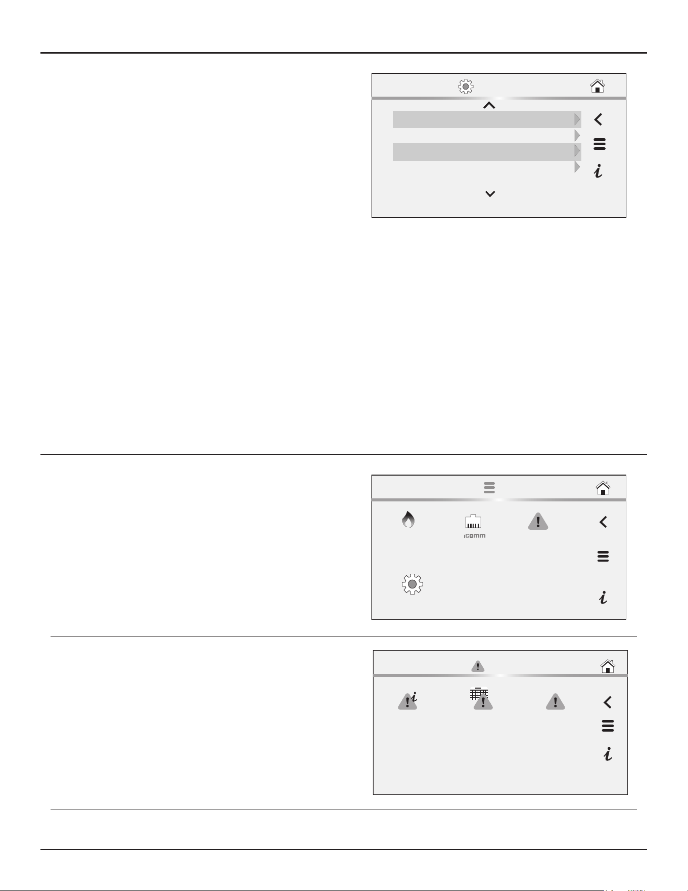
Control System Operation
High-Eciency Commercial Gas Water Heaters • 71
The Settings screen contains adjustable display options for viewing
information on the LCD screen.
•
Temperature Units
- Adjustable user setting that changes
temperature units display to Celsius °C or Fahrenheit °F.
•
Backlight Delay
- Adjustable user setting that determines how
long the LCD backlight remains illuminated after a key has been
pressed. Available settings are; Always Off, 10, 30 or 60 seconds
and Always On.
•
Brightness
- Adjustable user setting to adjust the LCD screen
contrast between text and background.
• These settings are adjusted in the same way as described
Operating Set-Point and Differential Adjustment
(page 65).
• Lock setpoint manager
• Date/Time
• Lock
• Show Contact
• Current Contact Info
• Leak Detection
• Audio Alert
• Tank Temp Probe Offset
• Use External Enable
• Disable Modulation
• Water Valve Cycle Time
• Language
Temp Units °F
Display Brightness 8
09/09/2020 12:34 AMDate/Time
30 secBacklight
SETTINGS
Current Fault
1. From the Home screen, press MENU icon.
The “Main Menu” screen will be displayed.
2. From the Main Menu, press the Faults icon to access the Fault Menu.
FAULTS
SETTINGS
MAIN MENU
HEATER
3. From the Fault Menu, press the Current Fault or Current Alert icon to
access the Current Fault screen.
FAULT MENU
FAULT
OCCURRENCE
FAULT
HISTORY
CURRENT
FAULT (NONE)
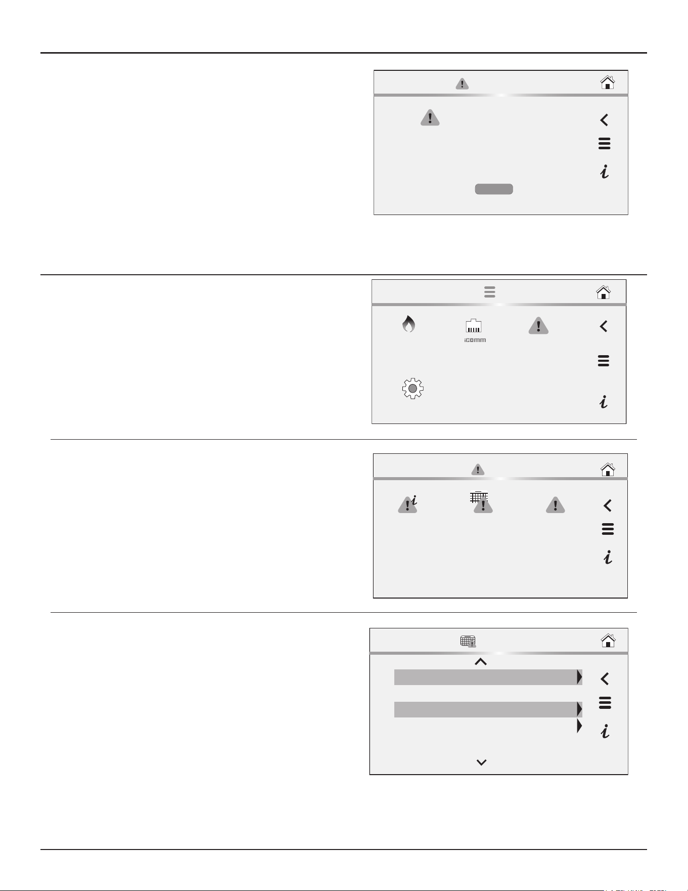
72 • High-Eciency Commercial Gas Water Heaters
Control System Operation
The Current Fault screen contains the current Fault or Alert error
message. The time the Fault or Alert message occurred appears
directly below. A brief description of what causes the particular Fault
or Alert condition appears below that.
Press the MORE button for more detailed service information and a
list of possible causes for the Fault or Alert condition.
See
Troubleshooting
(page 82) for more detailed information and
diagnostic procedures.
If there is no Fault or Alert condition active this menu will not contain
any information; “(none)” will be shown next to Current Fault in the
Fault menu.
CURRENT FAULT
CURRENT FAULT NAME
Occurred:
09/08/2020 12:34 AM
This will be a brief description of the fault. It will be
described in one or two sentences.
MORE
Fault History Menu
1. From the Home screen, press MENU icon.
The “Main Menu” screen will be displayed.
2. From the Main Menu, press the Faults icon to access the Fault Menu.
FAULTS
SETTINGS
MAIN MENU
HEATER
3. From the Fault Menu, press the Fault History icon to access the Fault
History screen.
FAULT MENU
FAULT
OCCURRENCE
FAULT
HISTORY
CURRENT
FAULT (NONE)
The Fault History screen contains a list of the last nine (9) Fault and
Alert messages with a time stamp. The newest event will replace the
oldest. Faults will clear after 30 days.
Press the Fault to view details for each Fault or Alert message stored.
FAULT HISTORY
1: High Temp Limit Exceeded (2)
07/13/2020 03:30 AM
2: Upper Temperature Probe Sensing Failure (3)
06/08/2020 04:06 AM
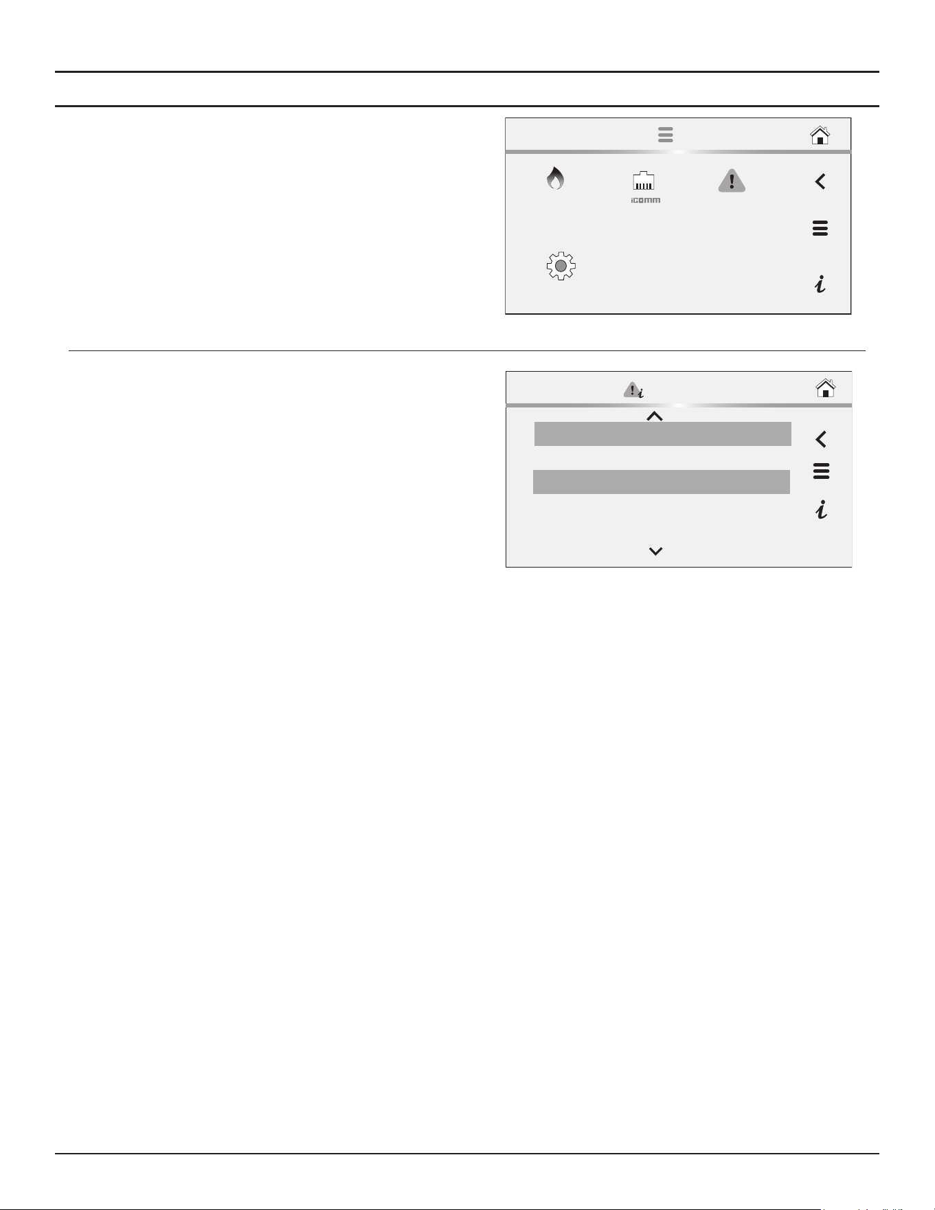
Control System Operation
High-Eciency Commercial Gas Water Heaters • 73
Fault Occurrence Menu
1. From the Home screen, press MENU icon.
The “Main Menu” screen will be displayed.
2. From the Main Menu, press the Faults icon to access the Fault Menu.
FAULTS
SETTINGS
MAIN MENU
HEATER
3. From the Faults Menu, press the Fault Occurrence icon to access the
Fault Occurrence screen.
The Fault Occurrence screen contains a running total of how many
times each Fault condition has occurred since the water heater was
first installed.
Hardware Fault 1
Software Failure 7
0
Software and FMM Key Incompatible
4
Missing Module
Fault Occurrence
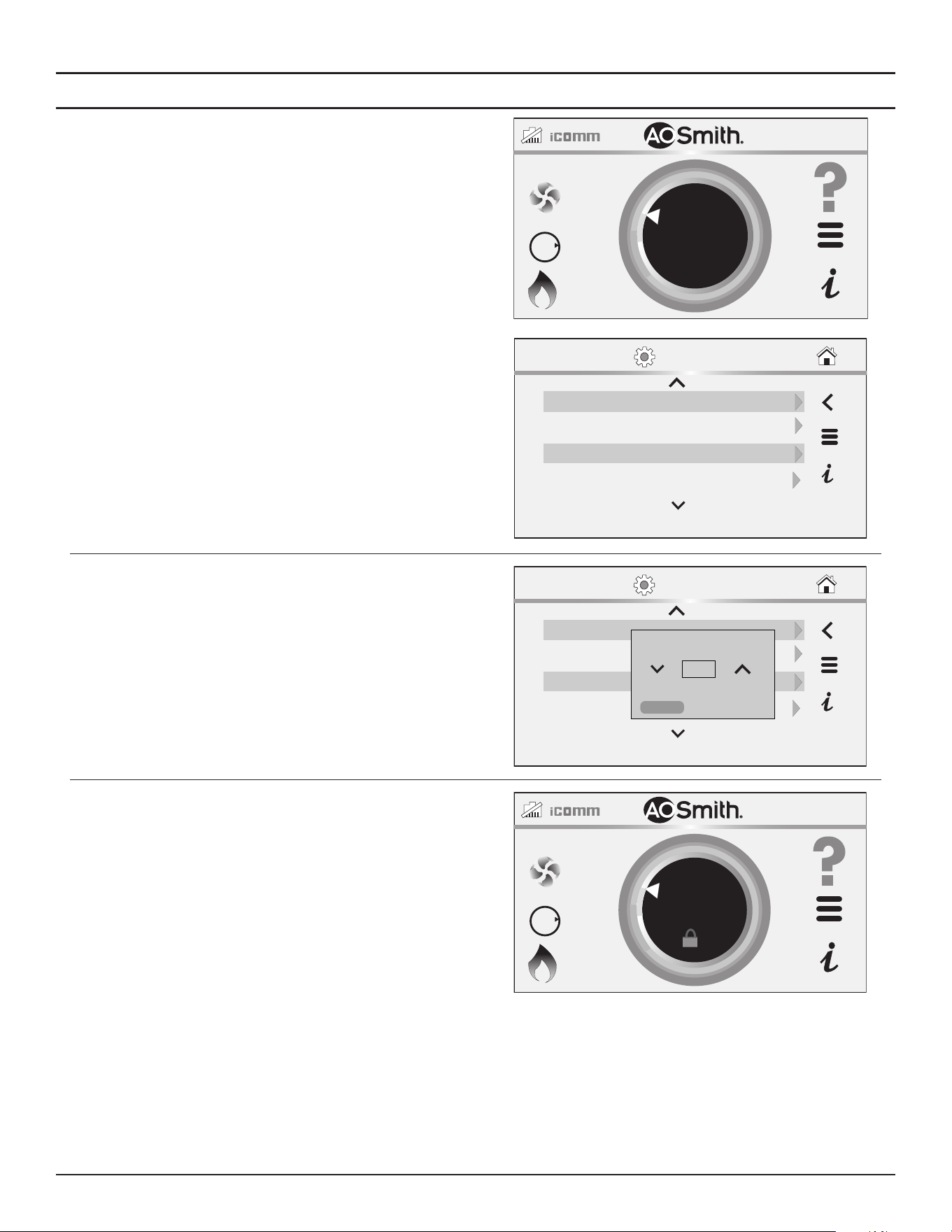
74 • High-Eciency Commercial Gas Water Heaters
Control System Operation
Lockout Function
1. From the Home screen, press MENU icon.
The “Main Menu” screen will be displayed.
2. From the Main Menu, press the Settings icon to access the Settings
screen.
3. Use the arrow buttons to scroll through the list to the Lock item.
4. Click on the arrow to the right to access the Lock dialog box.
BTH250-NAT
HEATING
118°F
120°F
SETPOINT
OFF
GAS
O
N
30 secBacklight
SETTINGS
Temp Units °F
04/28/2025 12:34 AMDate/Time
Brightness
8
5. Use the arrows in the Lock dialog box to toggle Yes to enable the lock
or No to disable the lock.
Note:
The lock is disabled by default from the factory.
Click Confirm to implement your selection.
SETTINGS
30 secBacklight
Temp Units °F
04/28/2025 12:34 AMDate/Time
Brightness
8
Lock
No
CONFIRM
CANCEL
6. Press and hold on the lock icon on the Home screen to unlock the
Setpoint settings
BTH250-NAT
HEATING
118°F
120°F
SETPOINT
OFF
GAS
O
N
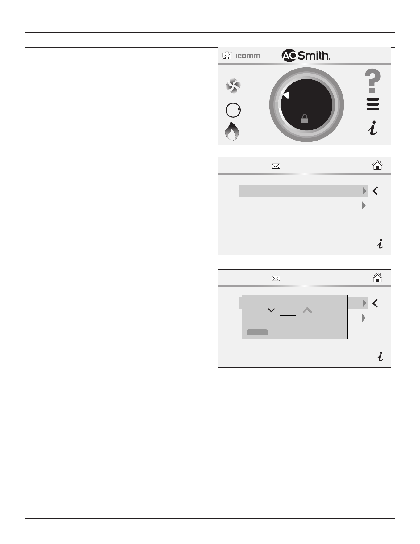
Control System Operation
High-Eciency Commercial Gas Water Heaters • 75
Restore Factory Defaults Function
1. Press and hold on the A. O. Smith logo on the Home screen.
The Service Information screen displays
BTH250-NAT
HEATING
118°F
120°F
SETPOINT
OFF
GAS
O
N
2. Select Restore User Defaults on the Service Information screen.
SERVICE INFORMATION
Restore User Defaults Display
Access Code
3. Ensure TRC is selected in the list menu, then press the Confirm button.
The original factory settings of the water heater are restored.
SERVICE INFORMATION
Restore User Defaults Display
Access Code
Restore User Defaults
TRC
CONFIRM
CANCEL
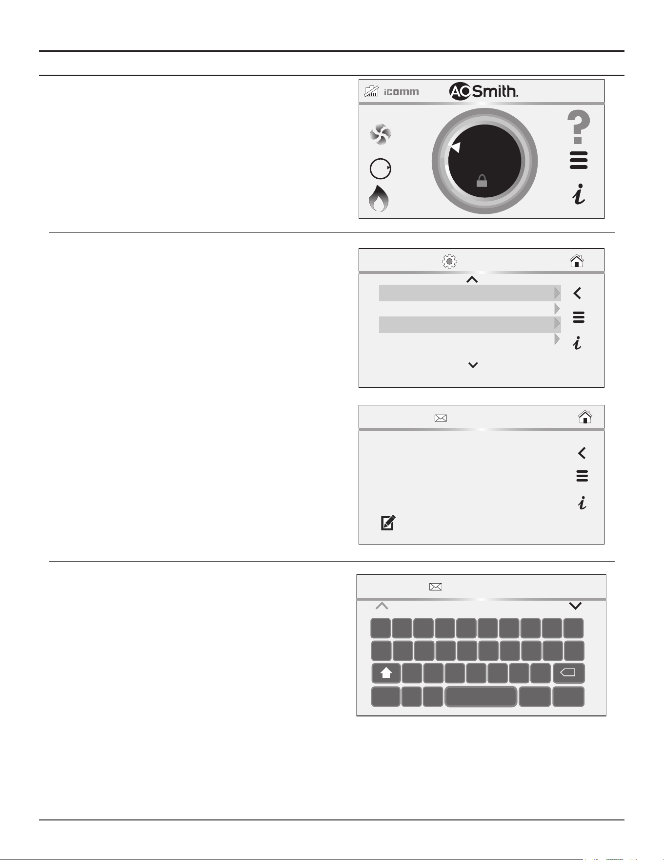
76 • High-Eciency Commercial Gas Water Heaters
Control System Operation
Service Contact Information
The control system has a menu that Installing contractors and/or service
agents can access to enter their contact information for customers. This
contact information will be displayed with all Fault and Alert messages.
1. From the Home screen, press the Main Menu icon. The Main Menu
screen displays.
2. From the Main Menu screen, press the Settings icon.
BTH250-NAT
HEATING
118°F
120°F
OFF
GAS
O
N
SETPOINT
3. Scroll down to the Settings Menu and select the Current Contact Info
item. The Contact Information screen displays.
Temp Units °F
Display Brightness 8
09/09/2020 12:34 AMDate/Time
30 secBacklight
SETTINGS
CONTACT INFORMATION
John Doe
Widgits LLC
123-456-7890
www.widgitsllc.com
4. To edit a contact information item, select it and press the Pencil icon.
5. Edit the item using the keyboard. Press the Save Key to save your data
after each entry.
Note: You can enable or disable the display of Contact info by editing the
“Show Contact” item on the Settings Menu.
CONTACT INFORMATION
John Doe
Q W R T YE I O PU
A S F G HD K L ‘J
C V BX MNZ
.,123
SAVE EXIT
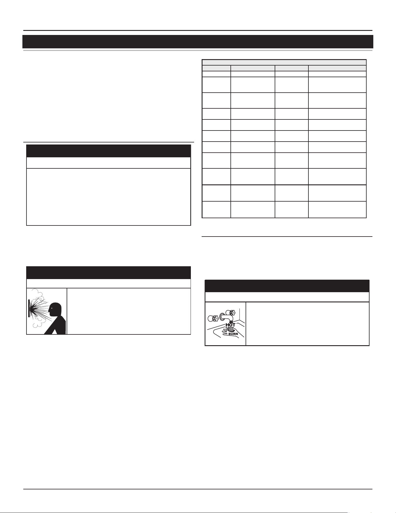
Maintenance
High-Eciency Commercial Gas Water Heaters • 77
MAINTENANCE
Keep water heater area clear and free from combustible materials, gasoline,
and other flammable vapors and liquids. See
Locating the Water Heater
(page 17).
Water heater maintenance includes periodic tank flushing and cleaning,
and removal of lime scale. The water heater should be inspected and
adjusted to maintain proper combustion. See
Initial Start Up
(page 55).
A periodic inspection of the venting system should be made, see
Table
22
(page 77). Where used, water circulating pump(s) should be oiled
according to the pump manufacturers recommendations.
Precautions
⚠
CAUTION
Safety Hazard
Do not operate the water heater if it has been exposed to or exhibits
the following:
• Exposed to flooding or water damage
• External damage.
• Firing without water.
• Sooting.
Do not operate the water heater until all corrective steps
have been made by a qualified service technician.
Never operate the water heater without first being certain it is filled with
water and a properly sized and rated Temperature-Pressure Relief Valve
is installed in the relief valve opening on the water heater. See
Water Line
Connections
(page 43).
• Overheated water can cause water tank explosion.
• A properly sized temperature and pressure relief
valve must be installed in the opening provided.
⚠
WARNING
Explosion Hazard
If overheating occurs or the gas supply fails to shut off, turn off the Main
Gas Shutoff valve. See
Figure 58
(page 50).
Table 22. Maintenance Schedule
Component Operation Interval Required
Tank Drain and Flush Every 6 Months See
Draining And Flushing.
Tank
Lime Scale Removal
(Water Less Than 25
Grains Hard)
Not Required N/A
Tank
Lime Scale Removal
(Water Greater Than
25 Grains Hard)
Annually
See
Lime Scale Removal
(page 78)
Burner
Flames
Inspection Every 3 Months
See
Burner Flame Inspection
(page 79).
Burner Inspection/Cleaning As Needed
Contact qualified agency or
professional.
Moving Parts Lubrication Not Required N/A
Powered
Anode Rods
Inspection/Cleaning Annually
See
Drain Valve and Access
Panels
(page 79).
T&P Valve Test Operation Semi Annually
See
Temperature-Pressure
Relief Valve Test
(page
80).
Vent System Inspection Annually
See
Vent System Mainte-
nance
(page 81).
Condensate
Neutraliza-
tion
Inspection Annually
See manual for the conden-
sate neutralization kit.
Condensate
Collection
Cleaning Annually
See
Vent System Mainte-
nance
(page 81).
DRAINING AND FLUSHING
It is recommended that the water heater storage tank be drained and
flushed every 6 months to reduce sediment buildup. The water heater
should be drained if being shut down during freezing temperatures. See
Features and Components
(page 10) for the location of the water heater
components described below.
⚠
DANGER
Burn Hazard
The discharge water from the drain valve is hot enough
to cause burns.
Keep your hands clear of the drain valve discharge
outlet.
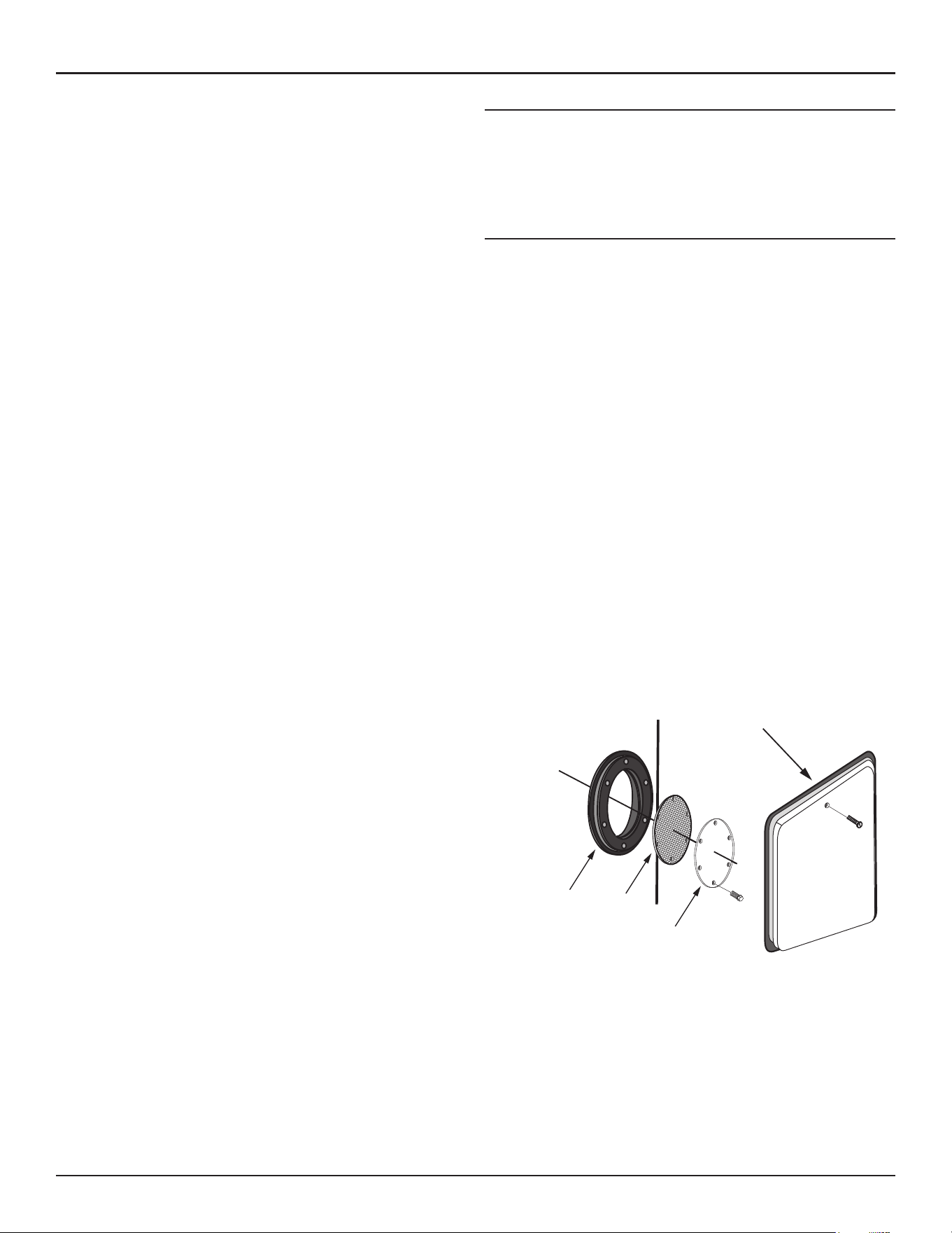
78 • High-Eciency Commercial Gas Water Heaters
Maintenance
Draining the Water Heater Storage Tank
1. Turn the Enable/Disable switch located on the front of the heater to
the Disabled position.
2. Turn off the electrical supply to the water heater.
3. Turn off the gas supply at the Main Gas Shutoff Valve if the water heater
is going to be shut down for an extended period.
4. Ensure the cold water inlet valve is open.
5. Open a nearby hot water faucet and let the water run until the water
is no longer hot.
6. Connect a hose to the water heater drain valve and terminate it to an
adequate drain.
7. Close the cold water inlet valve.
8. Open the water heater drain valve and allow all the water to drain
from the storage tank.
9. Close the water heater drain valve when all water in the storage tank
has drained.
10. Close the hot water faucet opened in Step 5.
11. If the water heater is going to be shut down for an extended period,
the drain valve should be left open.
Flushing the Water Heater Storage Tank
1. Turn the Enable/Disable switch located on the front of the heater to
the Disabled position.
2. Turn off the electrical supply to the water heater.
3. Ensure the cold water inlet valve is open.
4. Open a nearby hot water faucet and let the water run until the water
is no longer hot. Then close the hot water faucet.
5. Connect a hose to the drain valve and terminate it to an adequate drain.
6. Ensure the drain hose is secured before and during the entire flushing
procedure. Flushing is performed with system water pressure applied
to the water heater.
7. Open the water heater drain valve to flush the storage tank.
8. Flush the water heater storage tank to remove sediment and allow the
water to flow until it runs clean.
9. Close the water heater drain valve when flushing is completed.
10. Remove the drain hose.
11. Fill the water heater - see
Filling The Water Heater
(page 55).
12. Turn on the electrical supply to place the water heater back in operation.
13. Allow the water heater to complete several heating cycles to ensure
it is operating properly.
SEDIMENT REMOVAL
Waterborne impurities consist of the particles of soil and sand which settle
out and form a layer of sediment on the bottom of the tank.
For convenience, sediment removal and lime scale removal should be
performed at the same time.
Lime Scale Removal
When water is heated dissolved minerals in the water such as calcium
and magnesium carbonate (lime scale) become less soluble. As the water
temperature rises these minerals will precipitate or “fall out” of solution.
The amount of lime scale released from water is in direct proportion to
water temperature and usage. The higher the water temperature or water
usage, the more lime deposits are dropped out of the water.
Water hardness also affects lime scale accumulation. With the temperature
and usage being the same, hard water will release more lime scale than
softer water.
Lime scale reduces heating efficiency as it accumulates inside a water
heater. Heating transfer surfaces become coated with lime scale deposits
which increases fuel costs to operate the water heater. Lime scale deposits
can also cause rumbling and pounding noises as air molecules trapped in
the lime scale escape when heated. Lime scale accumulation also reduces
the life span of water heaters. For these reasons, a regular schedule for
deliming should be set up.
The depth of lime accumulation in the bottom of the water heater should
be measured periodically. Inspect by removing the clean-out cover once
every 6 months at first. Deliming maintenance should then be performed
based on the time it takes for 1 inch (2.5 cm) of lime to accumulate in the
bottom of the water heater.
Sediment and lime scale removal may be accomplished manually through
the clean-out opening furnished on the water heater, see
Figure 67
.
TANK
CLEANOUT
OPENING
CLEANOUT
COVER
CLEANOUT
GASKET
CLEANOUT
ACCESS PANEL
Figure 67. Clean-out Access
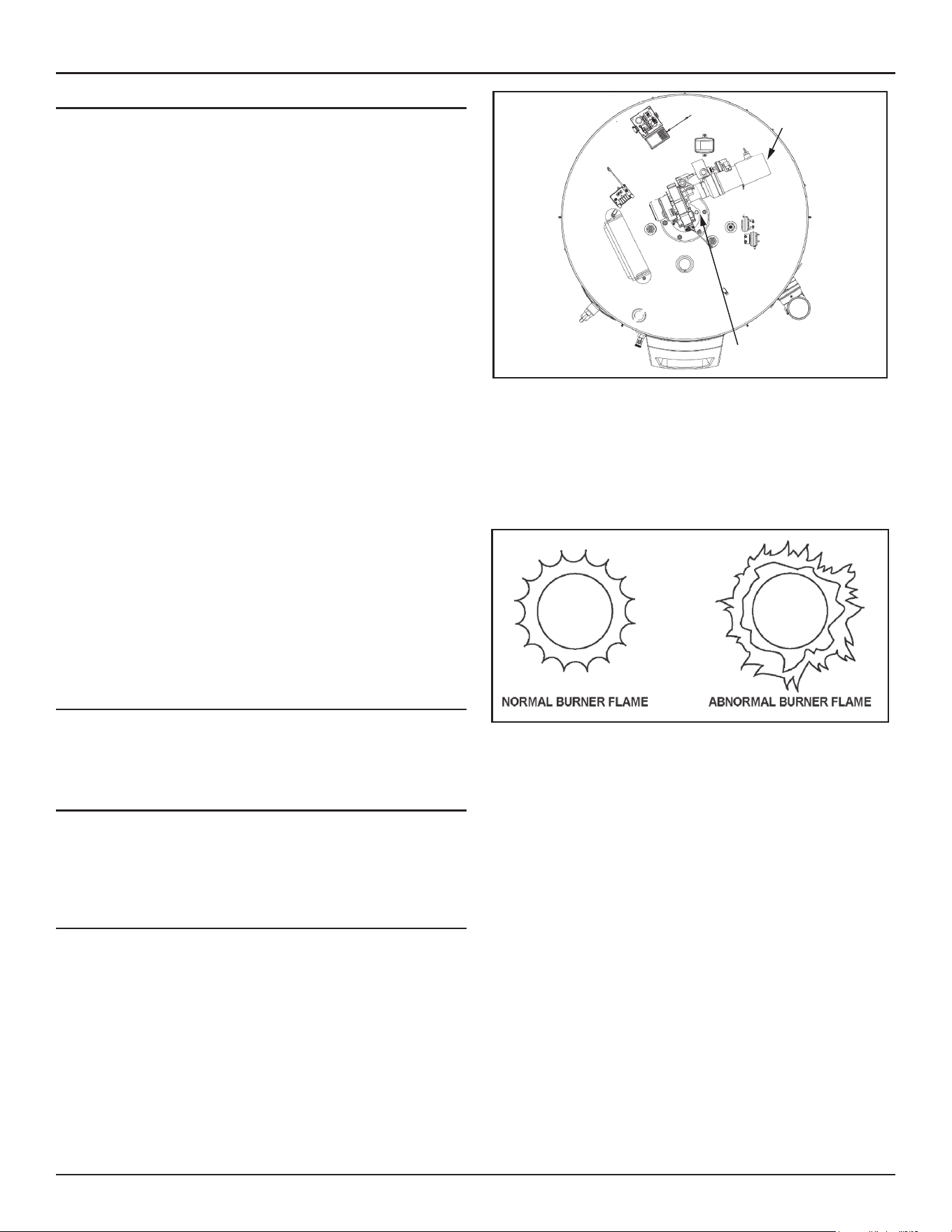
Maintenance
High-Eciency Commercial Gas Water Heaters • 79
Manual Lime Scale Removal
Note: Contact your local distributor or contact Technical Support to order
a new clean-out gasket. See the contact information label on the
water heater. Have the new gasket available before removing the
clean-out cover.
The clean-out opening is shown in
Figure 67
. To remove lime scale manually
through the clean-out opening proceed as follows:
1. Turn the Enable/Disable switch located on the front of the heater to
the Disabled position.
2. Turn off the electrical supply to the water heater.
3. The water heater must be drained, see
Draining And Flushing
(page
77), follow the instructions on how to drain the water heater.
4. Remove outer clean-out access panel from lower side of the water
heater jacket.
5. Remove the clean-out cover from clean-out opening.
6. Remove lime, scale and/or sediment using care not to damage the
glass-lining.
7. Install a new clean-out gasket if required.
8. Reinstall the clean-out cover. Be sure to draw plate up tight by tightening
screws securely.
9. Close the water heater drain valve.
10. Fill the water heater - see
Filling The Water Heater
(page 55).
11. Turn on the electrical supply to place the water heater back in operation.
See
Initial Start Up
(page 55).
12. Allow the water heater to complete several heating cycles to ensure
it is operating properly.
13. Check for water leakage.
14. Reinstall the clean-out access panel.
Chemical Lime Scale Removal
To dissolve and remove more stubborn lime scale deposits, white vinegar
should be used. Hydrochloric base acids must not be used to delime the
water heaters covered in this manual.
DRAIN VALVE AND ACCESS PANELS
The water heaters covered in this manual are equipped with a drain valve.
See
Features and Components
(page 10)
for location. The water heaters
covered in this manual are also equipped with a clean-out opening for
sediment and lime scale removal. See
Figure 67
(page 78).
BURNER FLAME INSPECTION
Check main burner every three months for proper flame characteristics.
You can see the burner flame through the sight glass on top of the burner
plate. To access the sight glass, you must remove the plastic cover.
Sight Glass
Inlet Air
Connection
Figure 68. Location of Sight Glass
The main burner should display the following characteristics:
• Provide complete combustion of gas.
• Cause rapid ignition and carry over of flame across entire burner.
• Give reasonably quiet operation during initial ignition, operation and
extinction.
• Cause no excessive lifting of flame from burner ports. See Figure 66.
Figure 69. Normal and Abnormal Burner Flames
If the preceding burner characteristics are not evident, check for
accumulation of lint or other foreign material that restricts or blocks the
air intake fitting or air intake terminal.
To ensure continued good performance, keep the area around the water
heater clean and free from lint and debris. Sweep the floor around the
water heater regularly. This will reduce the dust and dirt which can enter
the burner and heat exchanger, causing improper combustion and sooting.
If the air intake fitting and air intake terminal are clear and the burner
continues to exhibit abnormal flames, contact a qualified service agency
or have a qualified service professional inspect and clean the burner.
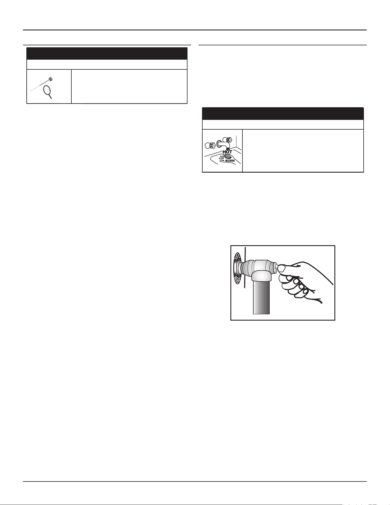
80 • High-Eciency Commercial Gas Water Heaters
Maintenance
ANODE ROD MAINTENANCE
CAUTION
Property Damage Hazard
Operating the water heater with depleted or
malfunctioning anodes can damage the water
heater.
Annual inspection and replacement of the anode
rod is required.
The water heaters covered in this manual are factory equipped with
powered anode rods mounted in the top of the unit. The anode rods are of
a permanent design and do not need replacing unless damaged, however,
inspection and cleaning should be performed once a year.
To inspect the powered anode, do the following:
1. Turn off electrical supply and gas supply to the water heater.
2. Shut off the water supply and open a nearby hot water faucet to
depressurize the water tank.
3. Drain approximately 5 gallons of water from tank. See
Draining And
Flushing
(page 77)
for proper procedures. Close drain valve.
4. Remove the wiring connection on the top of the powered anode.
5. Remove the powered anode by loosening the 3/4” NPT bushing that
forms the top of the anodes.
6. Remove the entire anode rod from the water heater for inspection.
• If undamaged and in working order, clean the anode rod with a
soft cloth and reinstall.
• If the anode needs to be replaced, obtain a new anode rod.
Apply thread-sealer tape or an approved pipe sealant on the
threads before installing the new powered anode rod.
Whether re-installing or replacing the powered anode rod, check for
any leaks and immediately correct if found.
7. Turn on water supply and open nearby hot water faucet to purge air
from water system.
8. Refill the water heater following the instructions for
Filling The Water
Heater
(page 55)
.
9. Restart the water heater as directed in this manual.
TEMPERATURE-PRESSURE RELIEF VALVE TEST
It is recommended that the Temperature-Pressure Relief Valve should be
checked to ensure that it is in operating condition every 6 months.
When checking the Temperature-Pressure Relief Valve operation, make
sure that (1) no one is in front of or around the outlet of the Temperature-
Pressure Relief Valve discharge line, and (2) that the water discharge will
not cause any property damage, as the water may be extremely hot. Use
care when operating valve as the valve may be hot.
⚠
DANGER
Burn Hazard
The discharge water from the temperature-pressure
relief valve is hot enough to cause burns.
Keep clear of the temperature-pressure relief valve
discharge outlet.
To check the relief valve, lift the lever at the end of the valve several times,
see
Figure 70
. The valve should seat properly and operate freely.
If after manually operating the valve, it fails to completely reset and
continues to release water, immediately close the cold water inlet to the
water heater and drain the water heater, see
Draining And Flushing
(page
77). Replace the Temperature-Pressure Relief Valve with a properly
rated/sized new one, see
Temperature-Pressure Relief Valve
(page 22)
and
Piping Diagrams
(page 102) for instructions on replacement.
Figure 70. T&P Relief Valve Discharge Pipe
If the Temperature-Pressure Relief Valve on the water heater weeps or
discharges periodically, this may be due to thermal expansion.
Note: Excessive water pressure is the most common cause of
Temperature-Pressure Relief Valve leakage. Excessive water system
pressure is most often caused by "thermal expansion" in a "closed
system." See
Thermal Expansion
(page 22)
and
Closed Water
Systems
(page 21). The Temperature-Pressure Relief Valve is not
intended for the constant relief of thermal expansion.
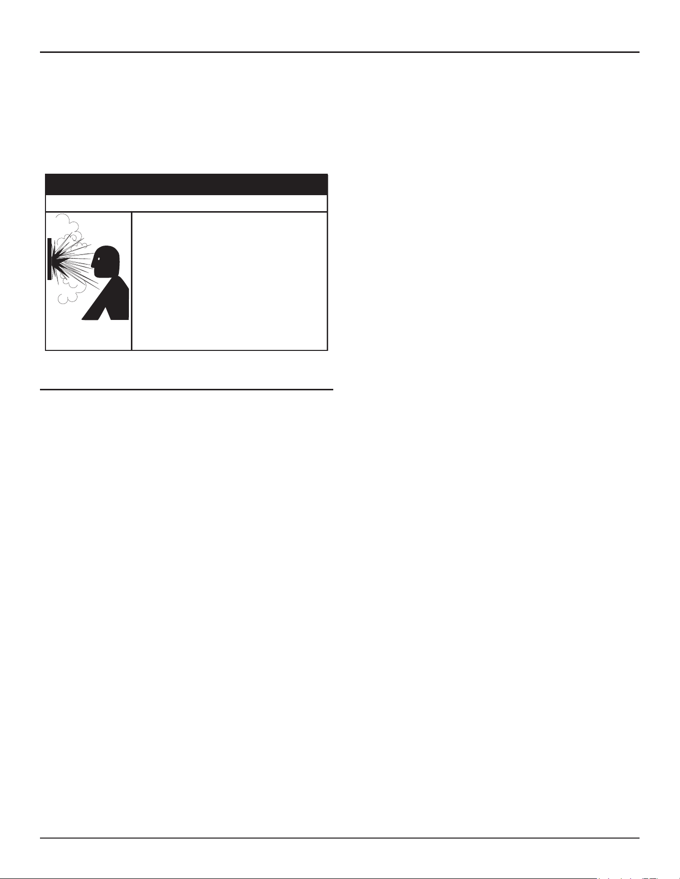
Maintenance
High-Eciency Commercial Gas Water Heaters • 81
Temperature-Pressure Relief Valve leakage due to pressure build up in a
closed system that does not have a thermal expansion tank installed is
not covered under the limited warranty. See Commercial Water Heater
Limited Warranty Insert.
Thermal expansion tanks must be installed on all closed water systems.
Do not plug the Temperature-Pressure Relief Valve opening. This can cause
property damage, serious injury or death.
Normal opera�on of the water heater can cause
it to become sufficiently over-heated and/or
over-pressurized that it can explode, resul�ng in
property damage, sever injury, or death.
To avoid this hazard, you must install a properly-
sized temperature-pressure relief valve in opening
provided.
• The temperature-pressure relief valve must
comply with ANSI Z21.22-CSA 4.4 and ASME
code.
• Do not plug, block, or cap the discharge line.
⚠
WARNING
Explosion Hazard
VENT SYSTEM MAINTENANCE
Examine the vent system every 6 months. Points of inspection are as
follows:
1. Check for obstructions and/or deterioration of the intake air and/or vent
piping and the intake air and vent terminations. Replace immediately
where needed.
2. The debris screens in the intake air and vent terminations should be
cleaned of foreign material and soot. See
Figure 28
(page 38).
Note:
Do not reach inside the vent termination when the heater is
in operation.
3. Check all vent system connections for leakage and repair or reseal as
necessary.
4. Inspect and clean the built-in condensate trap of any debris. See
Figure
11
(page 23) and
Figure 56
(page 49).
82 • High-Eciency Commercial Gas Water Heaters
TROUBLESHOOTING
STARTUP CONDITIONS
Smoke/Odor
It is not uncommon to experience a small amount of smoke and odor during
the initial start-up. This is due to burning off of oil from metal parts, and
will disappear in a short while.
Thermal Expansion
CAUTION
Property Damage Hazard
Avoid water heater damage from pressure fluctua�ons
in closed water systems.
• Fill tank with water before operating.
• Install thermal expansion tank if necessary.
• Do not apply heat to cold water inlet.
• Contact qualified installer or service agency.
Water supply systems may, because of such events as high line pressure,
frequent cut-offs, the effects of water hammer among others, have
installed devices such as pressure reducing valves, check valves, back flow
preventers, etc. to control these types of problems. When these devices
are not equipped with an internal by pass, and no other measures are
taken, the devices cause the water system to be closed. As water is heated,
it expands (thermal expansion) and closed systems do not allow for the
expansion of heated water.
The water within the water tank expands as it is heated and increases the
pressure of the water system. If the relieving point of the water heater’s
temperature-pressure relief valve is reached, the valve will release excess
pressure. The temperature-pressure relief valve is not intended for the
constant relief of thermal expansion. This is an unacceptable condition
and must be corrected. It is recommended that any devices installed
which could create a closed system have a by-pass and/or the system
have an expansion tank or device to relieve the pressure built by thermal
expansion in the water system. Expansion tanks are available for ordering
through a local plumbing contractor. Contact the local water heater supplier
or qualified service agency for assistance in controlling these situations.
OPERATIONAL CONDITIONS
Do not remove the powered anode rod leaving the tank unprotected. By
doing so, all warranty on the water heater tank is voided.
Having the 120 V power to the water heater turned off for extended periods
of time also leaves the tank unprotected and can void the warranty.
Air in Hot Water Faucets
Flammable hydrogen gases can form in water pipes.
The hydrogen can explode if it is exposed to flame and
can cause severe injury or death.
Keep all igni�on sources away from faucet when
turning on hot water.
⚠
WARNING
Explosion Hazard
Hydrogen Gas
Hydrogen gas can be produced in a hot water system that has not been
used for a long period of time (generally two weeks or more). Hydrogen
gas is extremely flammable and explosive. To prevent the possibility of
injury under these conditions, we recommend the hot water faucet,
located farthest away, be opened for several minutes before any electrical
appliances which are connected to the hot water system are used (such as
a dishwasher or washing machine). If hydrogen gas is present, there will
probably be an unusual sound similar to air escaping through the pipe as
the hot water faucet is opened. There must be no smoking or open flame
near the faucet at the time it is open.
INSTALLATION CHECKLIST
The list below represents some of the most critical installation
requirements that, when overlooked, often result in operational problems,
down time and needless parts replacement. This is not a complete list.
Before performing any troubleshooting procedures use the list below to
check for installation errors.
Note: Costs to correct installation errors are not covered under the limited
warranty. See Commercial Water Heater Limited Warranty Insert.
Ensure all installation requirements and instructions in this manual have
been maintained and followed.
Water Heater Location
1. Ensure proper clearances to combustibles are maintained and there
is sufficient room to service the water heater. See
Clearance To
Combustible Materials
(page 18).
2. Ensure the area is free of corrosive elements and flammable materials.
See the instructions in
Combustible Material Storage
(page 24).

High-Eciency Commercial Gas Water Heaters • 83
Venting
3. Ensure the intake air and/or vent (exhaust) piping is the correct size for
the installed length. See
Venting Requirements
(page 32).
4. Ensure the maximum equivalent length of pipe has not been exceeded
for the intake air and/or vent pipe. See
Table 7
and
Table 8
(page 33).
5. Ensure the maximum number of elbows has not been exceeded in
the intake air and/or vent pipe. See
Table 7
and
Table 8
(page 33).
6. Ensure the intake air screen has been removed from the intake air
connection on the water heater when installing the water heater in a
Direct Vent configuration. See
Figure 21
(page 35).
7. Ensure all exterior clearances for the intake air, vent, concentric, and
low profile terminations are maintained. See
Vertical Termination
Installation
(page 36),
Concentric Termination Installation
(page
41). These clearances and those cited by local and national codes
must be maintained.
Gas Supply And Piping
8. Ensure a supply gas regulator has been installed for each water heater.
See the requirements for a
Supply Gas Regulator
(page 20).
9. Ensure the supply gas line to each water heater meets the minimum
supply gas line size requirements. See the requirements for the
Gas
Supply Systems
(page 20)
and the installation instructions in
Gas Line
Sizing
(page 51) and
Gas Line Connection
(page 51).
Condensate Drain
Ensure the condensate drain is properly connected to the exhaust elbow
on the water heater and draining freely to a suitable floor drain. See
Figure
11
(page 23)
and
Condensate Drain Installation
(page 49).
Electrical Connections
10. Ensure the power supply connections to the water heater are polarity
correct. See the requirements for the
Power Supply
(page 20)
and
Electrical Wiring
(page 52).
11. Ensure the water heater is properly grounded. Flame sensing requires
an adequate earth ground. If the water heater is not properly grounded
it will cause ignition failure.
SEQUENCE OF OPERATION
Read the Sequence of Operation below before attempting to correct any
operational problems. Refer to
Features and Components
(page 10) for
the location of various water heater components described below. See
also
Sequence Of Operation
(page 83).
1. When the control system is first powered, during boot up, it will
display water heater model information during initialization. After a
few moments the control system LCD Touch Display which is part of
the UIM (user interface module) will display the default screen known
as the "Desktop" screen.
2. If the control system determines that the actual water temperature
inside the tank is below the programmed Operating Setpoint minus
the Differential setting, a heating cycle is activated.
3. The control system then performs selected diagnostic system checks.
This includes confirming the operating ready states of the blocked
exhaust, blocked intake and ECO (energy cut out) are operable.
4. If all diagnostic checks are successfully passed, the control system
energizes the Combustion Blower for prepurge.
5. The control system energizes the Spark Ignition Transformer.
6. The control system energizes the gas valve allowing gas to flow to the
Main Burner.
7. The control system monitors the flame sensor to confirm a flame is
present at the Main Burner. If a flame is not verified during the ignition
trial period the control system will try for ignition up to two more times.
If flame can not be verified after three trials for ignition, the control
system will lock out and display the “Ignition Failure” Fault message.
8. If a flame is verified, the control system will deenergize the Spark
Ignition Transformer and enter the heating mode where it will continue
heating the water until the Operating Setpoint is reached. At this point,
the control system will deenergize the gas valve and enter the post-
purge cycle (approximately 30 seconds).
9. The water heaters covered by this manual are capable of modulating
their firing rate. The firing rate is dictated by the hot water draw and
various other temperature limitations.
10. The Combustion Blower will run for the duration of the post-purge cycle
to purge the water heater of all combustion gases. When the post-purge
cycle is complete, the blower is deenergized and will coast to a stop.
11. The control system now enters the standby mode while continuing
to monitor the internal storage tank water temperature and the
state of other system devices. If the tank temperature drops below
the Operating Setpoint minus the Differential setting, the control will
automatically return to Step 2 and repeat the operating cycle.
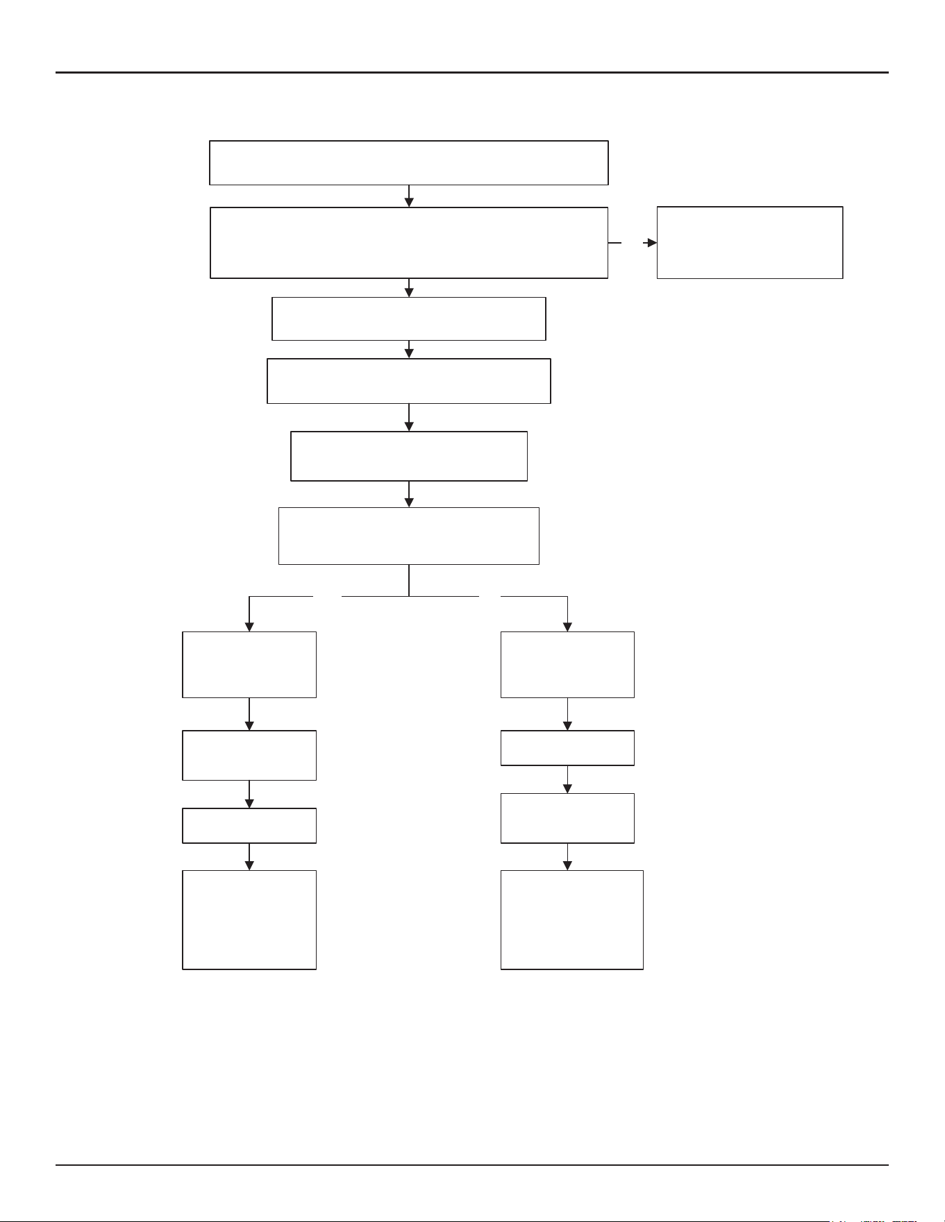
84 • High-Eciency Commercial Gas Water Heaters
Troubleshooting
YES NO
Water is heated to
set point
Gas Valve
de-energized
Inter-Purge cycle
Gas Valve
de-energized
Retries up to
two more times
Post-Purge cycle
Control System
Locks Out
“Ignition Failure”
Fault Message is
displayed
Water heater goes
into standby mode
If tank temperature drops below Operating Set Point minus
Differential setting a heating cycle is activated
Spark Ignition Transformer is energized
Gas Valve is energized
gas flows to Main Burner
Is flame sensed at the Main Burner?
(control system monitors the flame sensor)
Control System Locks Out
Displays Fault Message
NO
Combustion Blower is energized
Pre-Purge cycle
Control System performs diagnostic checks
Normal State of all pressure switches and ECO are checked
Sequence is shown with Enable/Disable Switch in the Enable position
Pressure switches and ECO are verified closed
Figure 71. Sequence of Operation
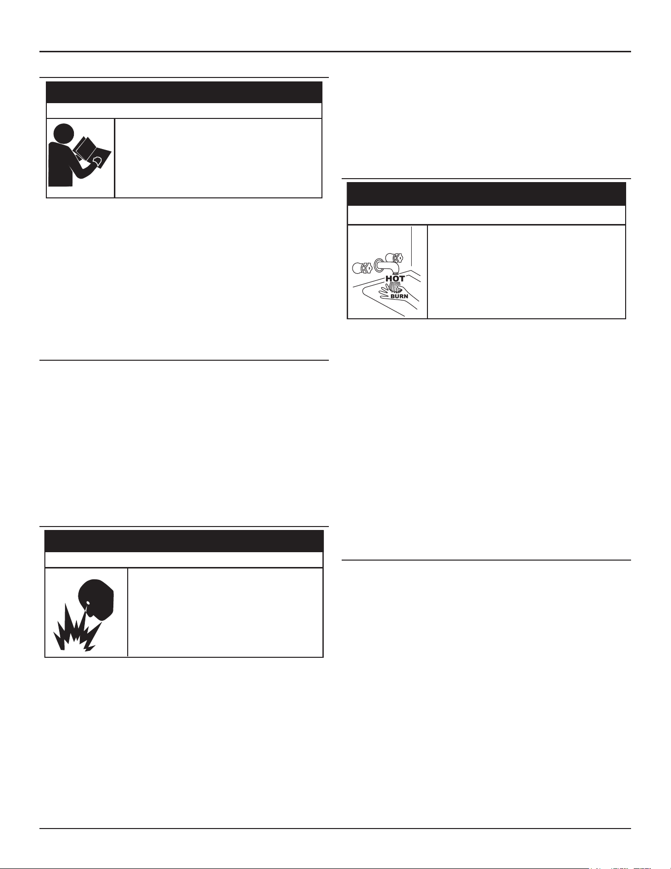
Troubleshooting
High-Eciency Commercial Gas Water Heaters • 85
OPERATIONAL PROBLEMS
Failure to follow these instrucons and safety
messages could result in death or serious injury.
Read and understand this instrucon manual and the
safety messages herein before installing, operang or
servicing this water heater.
This manual must remain with the water heater.
⚠
WARNING
Safety Hazard
This section of the manual is intended to be an aid in correcting common
operational problems, it is not all inclusive. The installer may be able
to observe and correct certain problems which might arise when the
water heater is first put into operation or when it is re-fired after a
prolonged shutdown. However, only qualified service agents, as defined
in
Qualifications
(page 8), using appropriate test equipment, should
perform any service procedures on the water heater.
Note: Contact Technical Support for further assistance or to locate a
qualified service agent in your area. See the contact information
label on the water heater.
Installation Errors
Operational problems on new installations are often the result of
installation requirements that have been overlooked rather than failed
components. IE: Rough starting and rough operation are often caused by
undersized supply gas lines and/or the absence of a supply gas regulator
at the water heater.
Prior to performing any operational checks inspect the water heater
installation to ensure all installation requirements and instructions have
been maintained and followed. See the
Installation Checklist
(page 82).
Note: Costs to correct installation errors are not covered under the limited
warranty. See Commercial Water Heater Limited Warranty Insert.
Rough Starting, Rough Operation
• Do not use water heater with any gas other than
the gas shown on the rating label.
• Excessive gas pressure to gas valve can cause
serious injury or death.
• Turn off gas lines during installation.
• Contact a qualified installer or service agency for
installation and service.
⚠
WARNING
Fire and Explosion Hazard
• Undersized supply gas line (low volume of supply gas) - see
Gas
Supply Systems
(page 20).
• Supply gas regulator is not installed per installation requirements
(erratic gas supply volume/pressures) - see
Supply Gas Regulator
(page 20).
• Excessive supply gas pressure - see
Table 5
(page 17)
and
Initial
Start Up
(page 55).
• Vent (exhaust) gas recirculation at the vent and intake air pipe
terminations on
Direct Vent Installation
- see
Direct Vent Installation
(page 34).
• Excessive equivalent lengths of intake air and/or vent (exhaust)
piping installed - see
Venting Requirements
(page 32).
• Debris clogging/blocking the intake air screen(s) - see
Figure 21
(page 35)
and
Figure 28
(page 38).
• Debris clogging/blocking the Main Burner - see
Figure 2
(page 11).
Momentary Ignition
Burn Hazard
• The combus�on chamber and burner
sleeve and housing become very hot
during opera�on.
• Do not reach into the burner housing or
combus�on chamber if the water heater is
s�ll hot.
• Allow the water heater to cool and always
use gloves when handling the main burner.
⚠
CAUTION
If the Main Burner ignites momentarily but does not sustain ignition, allow
the water heater to try to ignite up to two more times until control system
locks out and the Ignition Failure Fault message is displayed on the control
system's LCD. If the water heater is experiencing rough starts - see
Rough
Starting, Rough Operation
(page 85). For momentary ignition problems
without rough starting check the following:
• Undersized supply gas line (low volume of supply gas) - see
Gas
Supply Systems
(page 20).
• Supply gas regulator is not installed per installation requirements
(erratic gas supply volume/pressures) - see
Supply Gas Regulator
(page 20).
• See the list of possible causes and things to check and repair for
the Ignition Failure Fault message in
Fault and Alert Messages
(page
88).
• Debris clogging/blocking the intake air screen(s) - see
Figure 21
(page 35)
and
Figure 28
(page 38).
• Debris clogging/blocking the Main Burner - see
Figure 2
(page 11).
Not Enough Or No Hot Water
• No power to the water heater, check breaker and fuses.
• Enable/Disable switch in "Disabled" position. Set to Enable to allow
unit to operate.
• Hot water supply valve(s) to fixtures closed.
• Operating Setpoint is set too low, Differential setting is set too high.
See
Control System Operation
(page 63).
• Tank Probe Offset is causing the heating cycles to terminate
prematurely - see
Setpoint Manager
(page 66).
• Ensure there is not any external supervisory control (using the
enable/disable circuit) disabling heating operation.
• The heating capacity of the water heater has been exceeded, the
water heater is unable to meet demand.

86 • High-Eciency Commercial Gas Water Heaters
Troubleshooting
• Colder incoming water temperature lengthening the time required
to heat water to desired temperature.
• Hot water piping leaks, open faucets, water heater drain valve
leaking or open.
• Sediment or lime scale accumulation may be affecting water heater
operation. See
Maintenance
(page 77)
for sediment and lime scale
removal procedures.
• Water heater not firing at full input rating. Check actual firing rate
of the water heater, see instructions in
Checking The Firing Rate
(page 59). Note that the water heaters covered by this manual are
capable of modulating their firing rate. The firing rate is dictated by
the hot water draw and various other temperature limitations.
Water Is Too Hot
• Operating Setpoint is set too high. See
Operating Set-Point and
Differential Adjustment
(page 65).
• If installed, check Thermostatic Mixing Valve settings.
• Tank Probe Offset setting improperly set - see
Setpoint Manager
(page 66).
• Lime build-up on temperature probes. Inspect and Clean.
• Improper water piping - see
Water Heater Installation
(page 49).
Noisy Operation
• Sediment or lime scale accumulations can cause rumbling and
pounding noises during heating cycles. See
Maintenance
(page 77)
for sediment and lime scale removal procedures.
• Normal operating noise of electrical components; Combustion
Blower, transformer hum, relay contact closure.
Water Leakage Is Suspected
• Ensure the water heater drain valve is tightly closed.
• Check clean-out opening for leaks - see
Figure 5
(page 13).
• Check inlet/outlet water connections and system piping.
• Check the Temperature-Pressure Relief Valve.
• Excessive water temperature.
• Excessive water pressure.
• Defective Temperature-Pressure Relief Valve.
Note: Excessive water pressure is the most common cause of
Temperature-Pressure Relief Valve leakage. Excessive water system
pressure is most often caused by "thermal expansion" in a "closed
system." See
Closed Water Systems
(page 21) and
Thermal
Expansion
(page 22). The Temperature-Pressure Relief Valve is
not intended for the constant relief of thermal expansion.
Temperature-Pressure Relief Valve leakage due to pressure build up in a
closed system that does not have a thermal expansion tank installed is
not covered under the limited warranty. See Commercial Water Heater
Limited Warranty Insert.
Thermal expansion tanks must be installed on all closed water systems.
Smoke/Odor
It is not uncommon to experience a small amount of smoke and odor during
the initial start-up. This is due to burning off of oil from metal parts, and
will disappear in a short while.
Replacement Parts
Replacement parts may be ordered from the manufacturer, authorized
service agencies or distributors. When ordering parts be sure to have the
complete water heater Model Number, Serial Number and Series Number
available. This information can be found on the rating label affixed to the
water heater.
Refer to the parts list included with the water heater from the factory for
more information or contact Technical Support for assistance. See the
contact information label on the water heater.
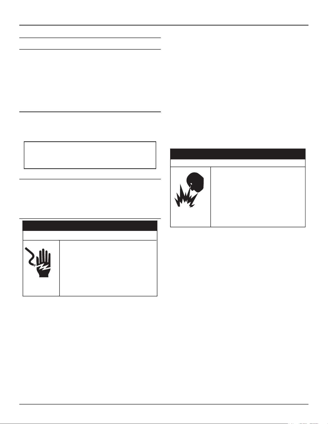
Troubleshooting
High-Eciency Commercial Gas Water Heaters • 87
FAULT AND ALERT CONDITIONS
Fault Conditions
When the control system shows a Fault condition it will display a Fault
message on the control system’s UIM with an exclamation “!” mark. The
control system will lockout and disable heating operation. To reset the
current fault, toggle the Enable/Disable switch on the front of the heater
from enable to disable, and then back to enable. If the condition that
caused the fault has not been resolved the fault will reappear. The water
heater must be serviced by a qualified service agent before operation
can be restored.
Alert Conditions
When the control system declares an Alert condition it will display an Alert
message on the control system’s LCD with a question “?” mark. The water
heater will continue to operate during an Alert condition but the water
heater must be serviced by a qualified service agent as soon as possible.
Verify the power to the water heater is turned off before
performing any service procedures. The Enable /Disable switch
on front panel disables the gas valve. Electrical supply must be
turned off at circuit breaker serving water heater.
Resetting Control System Lock Outs
To reset the control system from a lock out condition; turn the power supply
off at the breaker for approximately 20 seconds and then back on. Keep in
mind; if the condition that caused the Fault has not been corrected, the
control system will continue to lock out.
Diagnostic Checks
Servicing this water heater exposes you to
electrified components that can cause severe
injury or death if you touch them.
• Turn off power at the branch circuit breaker
serving the water heater before performing any
service.
• Label all wires prior to disconnecting when
performing service. Wiring errors can cause
improper and dangerous operation.
• Verify proper operation after servicing.
⚠
WARNING
Electrical Shock Hazard
The following section,
Fault and Alert Messages
(page 88), lists some of
the messages the control system will display on the LCD when there are
operational problems. This is not a complete list. Along with each of the
Fault and Alert messages described there will be a list of possible causes
and things to check and repair.
Only qualified service agents, as defined in
Qualifications
(page 8),
using appropriate test equipment, should perform any service procedures
on the water heater.
Note: If you are not qualified and licensed or certified as required by the
authority having jurisdiction to perform a given task do not attempt
to perform any of the diagnostic or service procedures described
in the following section.
If you do not understand the instructions in the following section do not
attempt to perform any procedures.
Contact Technical Support for further assistance or to locate a qualified
service agent in your area. See the contact information label on the water
heater.
Jumping out control circuits or components can
result in property damage, personal injury or death.
• Service should only be performed by a qualified
service technician using proper test equipment.
• Altering the water heater controls and/or wiring in
any way could result in permanent damage to the
controls or water heater and is not covered under
the limited warranty.
• Any bypass or alteration of the water heater
controls and/or wiring will result in voiding the
appl
iance warranty.
⚠
WARNING
Safety Hazard
88 • High-Eciency Commercial Gas Water Heaters
Troubleshooting
Fault and Alert Messages
Contact Technical Support for further assistance or to locate a qualified service agent in your area. See the contact-information label on the water heater.
Fault and Alert Messages
FAULT CODE Possible Causes - Check/Repair
Displayed Fault/Alert Message
2
Data Error Code:
(Resideo:131)
High Temp Limit Exceeded
The water heater is shut down due to high tank temperature.
The water temperature in the tank has exceeded the high
temperature limit.
1. Use a thermometer at a hot water fixture to confirm the
actual water temperature. If temperature is below 180˚
reset water heater.
2. If problem continues, contact technical support or refer to
the service handbook for further instructions.
CURRENT FAULT
High Temp Limit Exceeded
Occurred:
04/28/2025 12:34 AM
The water heater is shut down due to high
tank temperature.
MORE
3
Data Error Code:
(3, 30) NTC A short
(3, 31) NTC A open
(3, 32) NTC B short
(3, 33) NTC B open
(3,1001) NTC C open
(3,1002) NTC C short
(3,1018) NTC drift
Main Temperature Probe Failure
The indicated temperature probe might be shorted or open.
The control system has detected an issue with the main
temperature probe.
1. Ensure the wire connections for the main temp probe are
clean and secure.
2. Ensure the wire harness for the main temp probe is free
from damages.
3. If the problem continues, contact technical support or refer
to the service handbook for further instructions.
Note: If there are both main and lower temperature probes, the
Main Temperature probe is the main temperature probe.
CURRENT FAULT
Main Temperature Probe Failure
Occurred:
04/28/2025 12:34 AM
The indicated temperature probe might be
shorted or open.
MORE
4
Data Error Code:
(4,1006) NTC open
(4,1007) NTC short
Lower Temperature Probe Failure
The indicated temperature probe might be shorted or open.
The control system has detected an issue with the lower
temperature probe.
1. Ensure the wire connections for the lower temp probe are
clean and secure.
2. Ensure the wire harness for the lower temp probe is free
from damages.
3. If the problem continues, contact technical support or refer
to the service handbook for further instructions.
CURRENT FAULT
CURRENT FAULT
Lower Temperature Probe Failure
Occurred:
04/28/2025 12:34 AM
The indicated temperature probe might be
shorted or open.
MORE
5
Data Error Code:
(3,10xx) where xx =
5,9,13 or 17
Software Failure
Internal control failures are detected on TRC. Cycle power to the
water heater.
The controls system has detected a software issue.
1. Cycle the main power supply to the water heater by turning
off the breaker/disconnect, then wait approximately 30
seconds and turn main power supply back on.
2. If problem continues, contact Technical Support or refer to
the service handbook for further instructions.
CURRENT FAULT
Software Failure
Occurred:
04/28/2020 12:34 AM
Internal control failures are detected on
TRC. Cycle power to the water heater.
MORE
Troubleshooting
High-Eciency Commercial Gas Water Heaters • 89
Fault and Alert Messages
FAULT CODE Possible Causes - Check/Repair
Displayed Fault/Alert Message
6
(6,10xx) where xx =
4, 8, 12 or 16
OR
(6,80xx) where xx
= 1-10
Hardware Failure
Internal control failures are detected on the TRC. Cycle power to
the water heater.
The controls system has detected a hardware issue.
1. Cycle the main power supply to the water heater by turning
off the breaker/disconnect, then wait approximately 30
seconds and turn main power supply back on.
2. If problem continues, contact Technical Support or refer to
the service handbook for further instructions.
CURRENT FAULT
Hardware Failure
Occurred:
04/28/2025 12:34 AM
Internal control failures are detected on the
TRC. Cycle power to the water heater.
MORE
9
Data Error Code: 22
Power Supply Fault
The Control System is detecting a problem with the incoming
power supply.
1. Cycle the main power supply to the heater by turning
off the breaker/disconnect, then wait approximately 30
seconds and turn main power supply back on.
2. If problem continues, contact technical support or refer to
the service handbook for further instructions.
CURRENT FAULT
Power Supply Fault
Occurred:
04/28/2025 12:34 AM
The Control System is detecting a problem
with the incoming power supply.
MORE
20
Data Error Code:
(20,0)
Communication Failure
Communications between the display and the TRC is lost.
The control system has lost communications with UIM.
1. Cycle the main power supply to the heater by turning
off the breaker/disconnect, then wait approximately 30
seconds and turn main power supply back on.
2. Inspect the communication cable between the UIM and
the TRC to ensure the cable is not damaged and the
connections are clean and secure.
3. If problem continues, contact technical support, or refer to
the service handbook for further instructions.
CURRENT FAULT
Communication Failure
Occurred:
04/28/2025 12:34 AM
Communications between the display and
the TRC is lost.
MORE
25
Data Error Code:
(4,1010) NTC open
(4,1011) NTC short
Flue Gas Temperature Probe Failure
The flue gas temperature probe might be shorted or open.
The control system has detected an issue with the flue gas
temperature probe.
1. Cycle the main power supply to the heater by turning
off the breaker/disconnect, then wait approximately 30
seconds and turn main power supply back on.
2. If problem continues, contact technical support for further
instructions.
CURRENT FAULT
Flue Gas Temperature
Probe Failure
Occurred:
04/28/2025 12:34 AM
The flue gas temperature probe might be
shorted or open.
MORE
90 • High-Eciency Commercial Gas Water Heaters
Troubleshooting
Fault and Alert Messages
FAULT CODE Possible Causes - Check/Repair
Displayed Fault/Alert Message
26
Data Error Code:
(4,1014) NTC open
(4,1015) NTC short
Recirc Temperature Probe Failure
The recirculation temperature probe might be shorted or open.
The control system has detected an issue with the recirc
temperature probe.
1. Cycle the main power supply to the heater by turning
off the breaker/disconnect, then wait approximately 30
seconds and turn main power supply back on.
2. If problem continues, contact technical support for further
instructions.
CURRENT FAULT
Recirc Temperature
Probe Failure
Occurred:
04/28/2025 12:34 AM
The recirculation temperature probe might
be shorted or open.
MORE
31
Data Error Code:
(31,7002) or
(31, 7003) or
(31, 7004)
Water Leak Detected
A water leak or other water-present condition is being detected.
Check for a leak or other water problem at the water sensor.
The control system has detected a leak near the heater.
1. Inspect the area around the heater for signs of moisture.
2. Inspect all threaded fittings connected to the water heater
for signs of moisture.
3. Inspect the exhaust elbow connection to the heater for
signs of moisture.
4. Inspect the cleanout cover for signs of moisture.
5. Using litmus strips for pH testing to identify if the moisture
is condensate or water from the tank.
6. Condensation from the exhaust will be highly acidic.
7. If problem continues, contact technical support for further
instructions.
CURRENT FAULT
Water Leak Detected
Occurred:
04/28/2025 12:34 AM
A water leak or other water-present
condition is being detected. Check for a leak
or other water problem at the water sensor.
MORE
32
Data Error Code:
(32, 7001)
Leak Sensor Disconnected
The leak sensor is no longer being detected by the controller.
The control system has detected that the leak detector has been
disconnected.
1. Ensure the leak detector is securely connected to the water
heater.
2. Ensure the leak detector harness is securely connected to
the TRC at terminal J6 pins 1 and 11.
3. If problem continues, contact technical support for further
instructions.
CURRENT FAULT
Leak Sensor Disconnected
Occurred:
04/28/2025 12:34 AM
The leak sensor is no longer being detected
by the controller.
MORE
33
Data Error Code:
(33, 60x7) where
x = 0 is on TRC board
anode circuit.
x = 1 is CPAM 1,
x = 2 is CPAM 2 etc.
Anode Shorted
The powered anode is shorted to earth ground or to the tank.
The Control System has detected that the anode rod has shortage
to the tank.
1. Inspect anode wire connection for corrosion, moisture, or
other contaminates.
2. Ensure wire connection on both ends is secure.
3. Ensure anode wire harness is not damaged.
4. If problem continues, contact technical support for further
instructions.
CURRENT FAULT
Anode Shorted
Occurred:
04/28/2025 12:34 AM
The powered anode is shorted to earth
ground or to the tank.
MORE
Troubleshooting
High-Eciency Commercial Gas Water Heaters • 91
Fault and Alert Messages
FAULT CODE Possible Causes - Check/Repair
Displayed Fault/Alert Message
34
Data Error Code:
(34, 60x4) where
x = 0 is on TRC board
anode circuit.
x = 1 is CPAM 1,
x = 2 is CPAM 2 etc.
No Water
No water is detected by the powered anode.
The Control System is not detecting water in the tank.
1. Ensure there is water in the tank by following Fill the Tank
Instructions found in the installation manual.
2. Inspect anode wire connection for corrosion, moisture, or
other contaminates.
3. Ensure wire connection on both ends is secure.
4. Ensure anode wire harness is not damaged.
5. If problem continues, contact technical support for further
instructions.
CURRENT FAULT
No Water
Occurred:
04/28/2025 12:34 AM
No water is detected by the powered anode.
MORE
36
Data Error Code: 244
(36, 2440x)
x = 1 to 9 are reason
codes.
Weak Flame Signal
The Combustion Safety Control (CSC) is detecting low-flame
generated current.
The control system has detected a weak flame signal
1. Ensure that the flame sensor wire harness is free of
damages
2. Ensure that the flame sensor wire connection on both ends
is secure and free of contaminates
3. Remove flame sensor and inspect for contaminates or
damages in ceramic insulator
4. Clean flame sensor rod with steel wool
5. If the problem continues, contact technical support, or refer
to the service handbook for further instructions
CURRENT FAULT
Weak Flame Signal
Occurred:
04/28/2025 12:34 AM
The Combustion Safety Control (CSC) is
detecting low-flame generated current.
MORE
37
Data Error Code:
2, 130
(37, 2)
Or
(37, 130)
Flame Sensor Error
The control system has detected a flame sensor error.
The flame-sense rod is detecting a flame signal when the gas valve
is supposed to be off.
The control system has detected a flame sensor error.
1. Ensure that the flame sensor wire harness is free of
damages.
2. Ensure that the flame sensor wire connection on both ends
is secure and free of contaminates.
3. Remove flame sensor and inspect for contaminates or
damages in ceramic insulator.
4. Clean flame sensor rod with steel wool.
5. If the problem continues, contact technical support, or refer
to the service handbook for further instructions.
CURRENT FAULT
Flame Sensor Sensing Error
Occurred:
04/28/2025 12:34 AM
The control system has detected a flame
sensor error.
MORE
92 • High-Eciency Commercial Gas Water Heaters
Troubleshooting
Fault and Alert Messages
FAULT CODE Possible Causes - Check/Repair
Displayed Fault/Alert Message
38
(Resideo 129, 147,
241)
or 38
Data Error Code:
(38, 129) or
(38, 147) or
(38, 241) or
(38, 38)
Ignition Failure
The control system failed to sense a flame signal during the
ignition sequence.
The control system failed to sense a flame signal during the
ignition sequence
1. Verify that the gas supply, venting, and intake air pipes are
installed according to the instruction manual provided with
the water heater.
2. If the problem continues, contact technical support, or refer
to the service handbook for further instructions.
CURRENT FAULTCURRENT FAULT
CURRENT FAULT
Ignition Failure
Occurred:
04/28/2025 12:34 AM
The control system failed to sense a flame
signal during the ignition sequence.
MORE
41
Data Error Code:
(41, 1003)
High Temperature Warning
The main temperature probe exceeds 190°F.
The water temperature in the tank has exceeded the high
temperature warning temperature. the warning will reset when
tank temperature drops below 180°F.
1. Reset the water heater by toggling the Enable/Disable
switch to disable and back to enable.
2. If the problem continues, use a thermometer at a hot water
fixture to confirm the water temperature.
3. If the problem continues, contact technical support or refer
to the service handbook for further instructions.
CURRENT FAULT
CURRENT FAULT
CURRENT FAULT
Temp High Limit
Occurred:
04/28/2025 12:34 AM
The primary temperature exceeds the
high-limit setpoint.
MORE
42
Clock Not Set
Clock (time and date) are not set.
Check the iComm connection (if equipped) and reconnect for
automatic calendar updates.
The control system recognized that the clock is not set.
1. Refer to the installation manual for instructions on how to
set the clock.
2. If the problem continues, contact technical support for
further instructions.
CURRENT FAULT
CURRENT FAULT
CURRENT FAULT
Clock Not Set
Occurred:
09/08/2020 12:34 AM
Clock (time and date) are not set.
MORE
Troubleshooting
High-Eciency Commercial Gas Water Heaters • 93
Fault and Alert Messages
FAULT CODE Possible Causes - Check/Repair
Displayed Fault/Alert Message
201
Data Error Code: 71
(201, 71)
Blocked Air Intake
There is a restriction in the air intake. Check the intake pipe and
termination for blockage.
The control system has detected a blockage in the intake air pipe.
1. Ensure that the intake air pipe installed according to the
manufacturer’s installation manual.
2. Ensure that all horizontal pipe runs are properly sloped to
prevent moisture from accumulating and restricting air flow.
3. Inspect the inside of the intake air pipe from the connection
at the blower, all the way to the outside termination for
restrictions.
4. Inspect the plastic sensing tube to the blocked intake air
pressure switch to ensure there are no restrictions.
5. Ensure the blocked intake air pressure switch wires are free
from damages and contaminates.
6. Ensure wire connections are secure and free from
contaminates.
7. If problem continues, contact technical support, or refer to
the service handbook for further instructions.
CURRENT FAULTCURRENT FAULT
CURRENT FAULT
Blocked Air Intake
Occurred:
04/28/2025 12:34 AM
There is a restriction in the air intake. Check
the intake pipe and termination for
blockage.
MORE
202
Data Error Code: 70
(202, 70)
Blocked Exhaust
There is a restriction in exhaust pipe. Check exhaust pipe and
termination for blockage.
The control system has detected a blockage in the exhaust vent
pipe.
1. Ensure that the exhaust vent pipe installed according to the
manufacturer’s installation manual.
2. Ensure that all horizontal pipe runs are properly sloped to
prevent moisture from accumulating and restricting air flow.
3. Inspect the inside of the exhaust vent pipe from the water
heater connection all the way to the outside termination for
restrictions.
4. Inspect the plastic sensing tube to the blocked exhaust
pressure switch to ensure there are no restrictions.
5. Ensure the blocked exhaust pressure switch wires are free
from damages and contaminates.
6. Ensure wire connections are secure and free from
contaminates.
7. If problem continues, contact technical support, or refer to
the service handbook for further instructions.
CURRENT FAULT
Blocked Exhaust
Occurred:
04/28/2025 12:34 AM
There is a restriction in exhaust pipe. Check
exhaust pipe and termination for blockage.
MORE
205
Data Error Code:
(205,200x)
Where:
x =2 if the key is
uninitialized
x=3 if key
configuration is
corrupt.
Software and FMM Incompatible
The TRC version is older than the TRC version stored in key.
The control system has detected a device that is incompatible
1. Contact Technical Support for further instructions.
CURRENT FAULT
Software and FMM Key Incompatible
Occurred:
04/28/2025 12:34 AM
The TRC version is older than the TRC
version stored in key.
MORE
94 • High-Eciency Commercial Gas Water Heaters
Troubleshooting
Fault and Alert Messages
FAULT CODE Possible Causes - Check/Repair
Displayed Fault/Alert Message
206
Data Error Code:
(206, 2011)
CPAM Disconnected
Communication with the anode module has been lost.
The control system has detected that the CPAM is disconnected
1. Ensure CPAM is powered
2. Ensure wire connections are secure and free of
contaminates
3. Ensure wire harness is free of damages
4. If problem continues, contact technical support or refer to
the service handbook for further instructions
CURRENT FAULT
CPAM Disconnected
Occurred:
04/28/2025 12:34 AM
Communication with the anode module has
been lost.
MORE
207
Data Error Code:
(207, 35)
CSC Disconnected
The control system has detected that the CSC is disconnected.
1. Ensure the communication cable is securely connected
between the TRC on terminal J4 and the CSC on terminal
X10.
2. If problem continue, contact technical support for further
instructions.
CURRENT FAULT
CSC Disconnected
Occurred:
04/28/2025 12:34 AM
Communication with the anode module has
been lost.
MORE
209
Data Error Code:
(209, 2013)
Water Valve Module Disconnected
Communication with the water valve module has been lost.
The control system has detected that the Vavle Module is
disconnected.
1. Ensure Valve module is powered.
2. Ensure wire connections are secure and free of
contaminates.
3. Ensure wire harness is free of damages.
4. If problem continues, contact technical support or refer to
the service handbook for further instructions.
CURRENT FAULT
Water Valve Module Disconnected
Occurred:
04/28/2024 12:34 AM
Communication with the water valve module
has been lost.
MORE
210
Data Error Code:
(210, 35)
Auto Test Complete
Cycle Main Power to water heater. If problem continues, contact
technical support for further instructions.
CURRENT FAULT
Auto Test Complete/Passed
Occurred:
04/28/2025 12:34 AM
No action required.
MORE
Troubleshooting
High-Eciency Commercial Gas Water Heaters • 95
Fault and Alert Messages
FAULT CODE Possible Causes - Check/Repair
Displayed Fault/Alert Message
211
Data Error Code:
(211, 133)
No Blower Speed Feedback
The control system has not detected the correct feedback from
the blower when a command was sent to the blower to operate.
1. Ensure both wire connections to the blower and to the
control system is secure and free of contaminates.
2. Ensure the wire harnesses are free from damages.
3. If problem continue, contact technical support, or refer to
the service handbook for further instructions.
CURRENT FAULT
No Blower Speed Feedback
Occurred:
04/28/2025 12:34 AM
The control system has detected an issue
with the main temperature probe.
MORE
212
Data Error Code:
(212, xxx) where xxx -
142, 143,
144 or 146
Main Temperature Probe Failure
The control system has detected an issue with the main
temperature probe.
The control system has detected an issue with the main
temperature probe.
1. Ensure the wire connections for the main temp probe are
clean and secure.
2. Ensure the wire harness for the main temp probe is free
from damages.
3. If the problem continues, contact technical support or refer
to the service handbook for further instructions.
CURRENT FAULT
Main Temperature Probe Failure
Occurred:
04/28/2025 12:34 AM
The control system has detected an issue
with the main temperature probe.
MORE
213
Data Error Code:
(213, 136) or
(213, 243)
Hardware Failure
The control system has detected a flame sensor error.
1. Ensure that the flame sensor wire harness is free of
damages.
2. Ensure that the flame sensor wire connection on both ends
is secure and free of contaminates.
3. Remove flame sensor and inspect for contaminates or
damages in ceramic insulator.
4. Clean flame sensor rod with steel wool.
5. If the problem continues, contact technical support, or refer
to the service handbook for further instructions.
CURRENT FAULT
Hardware Failure
Occurred:
04/28/2025 12:34 AM
The control system has detected a flame
sensor error.
MORE
214
Data Error Code:
(214, xxx) where xxx
=149, 153, 155 or 157
Software Failure
The CSC has detected a software issue.
1. Cycle the main power supply to the water heater by turning
off the breaker/disconnect, then wait approximately 30
seconds and turn main power supply back on.
2. If problem continues, contact Technical Support or refer to
the service handbook for further instructions.
CURRENT FAULT
Software Failure
Occurred:
04/28/2025 12:34 AM
The CSC has detected a software issue.
MORE
96 • High-Eciency Commercial Gas Water Heaters
Troubleshooting
Fault and Alert Messages
FAULT CODE Possible Causes - Check/Repair
Displayed Fault/Alert Message
215
Data Error Code:
(215, 2400x) where
x is the failed
calibration reason
described in the
service handbook.
Calibration Error
The CSC has detected a calibration error.
1. The CSC has detected a software issue.
2. Cycle the main power supply to the water heater by turning
off the breaker/disconnect, then wait approximately 30
seconds and turn main power supply back on.
3. If problem continues, contact Technical Support or refer to
the service handbook for further instructions.
CURRENT FAULT
Calibration Error
Occurred:
04/28/2025 12:34 AM
The CSC has detected a calibration error.
MORE
216
Data Error Code:
(216, 137)
Gas Valve Circuit Fault
The control system has detected a fault with the Gas Valve Circuit.
1. Ensure wire connections on both ends are secure and free
of contaminates.
2. Ensure wire harness is not damaged.
3. If problem continues, contact technical support, or refer to
the service handbook for further instructions.
CURRENT FAULT
Gas Valve Circuit Fault
Occurred:
04/28/2025 12:34 AM
The control system has detected a fault with
the Gas Valve Circuit.
MORE
217
Data Error Code:
(217, 242)
MDT Fault
The control system has detected a fault with the Motor Driven
Throttle (MDT).
1. Ensure wire connections on both ends are secure and free
of contaminates.
2. Ensure wire harness is not damaged.
3. If problem continues, contact technical support, or refer to
the service handbook for further instructions.
CURRENT FAULT
MDT Fault
Occurred:
04/28/2025 12:34 AM
The control system has detected a fault with
the Motor Driven Throttle (MDT).
MORE
218
Data Error Code:
(209, 2014)
BMS Module Disconnected
Communication with the BMS module has been lost.
The control system has detected that the BMS is disconnected.
1. Ensure BMS module is powered.
2. Ensure wire connections are secure and free of
contaminates.
3. Ensure wire harness is free of damages.
4. If problem continues, contact technical support or refer to
the service handbook for further instructions.
CURRENT FAULT
BMS Module Disconnected
Occurred:
04/28/2025 12:34 AM
Communication with the BMS module has
been lost.
MORE
Troubleshooting
High-Eciency Commercial Gas Water Heaters • 97
Fault and Alert Messages
FAULT CODE Possible Causes - Check/Repair
Displayed Fault/Alert Message
219 The central control board (TRC) is detecting low-resistance or a
short to earth ground or the tank.
Possible Causes:
1. Water at anode area.
2. Contamination (solder, Loctite, WD40 etc.) between the
anode top and the surrounding metal.
3. Sediment build up with a possible bridge to tank.
4. A loose anode wire touching the tank.
5. A bent anode shorting to the tank or an element.
CURRENT FAULT
Anode Shorted
Occurred:
04/28/2025 12:34 AM
The external powered anode circuit is
shorted to earth ground or the tank.
MORE
220 Cycle the main power to the unit off and then on.
The commercial power anode module (CPAM) needs to be
replaced.
CURRENT FAULT
Power Anode Module failure
Occurred:
09/08/2020 12:34 AM
The external powered anode circuit has a
failure.
MORE
221
Data Error Code:
13
Reset Lockout
The control system has detected a Reset Lockout
1. Cycle the main power to the water heater.
2. If problem continues, contact technical support, or refer to
the service handbook for further instructions.
CURRENT FAULT
Reset Lockout
Occurred:
04/28/2025 12:34 AM
The Combustion Safety control (CSC)
detected more than 5 resets within 15
minutes.
MORE
222
Data Error Code:
(222, 2001)
FMM Missing
The control system has detected that the Flex Memory Module
(FMM) is either missing or disconnected.
1. Ensure the wire connections are secure and free of
contaminates.
2. Ensure wire connection at terminal J2 on the TRC is
secure.
3. Ensure all wire harnesses are free from damages.
4. Cycle the main power to the water heater.
5. If problem continues, contact technical support for further
instructions.
CURRENT FAULT
FMM Missing
Occurred:
04/28/2025 12:34
The control system has detected that the
Flex Memory Module (FMM) is either
missing or disconnected.
MORE
Troubleshooting
High-Eciency Commercial Gas Water Heaters • 99
Fault and Alert Messages
FAULT CODE Possible Causes - Check/Repair
Displayed Fault/Alert Message
227
(227, 4001)
FMM Incompatible
The control system has detected that the Software Version on
the Flex Memory Module (FMM) is outdated.
The control system has detected that the Software Version on
the Flex Memory Module (FMM) is outdated
1. Typically caused by replacing control system components with
an older revision software
2. Contact technical support for further instructions
CURRENT FAULT
FMM Incompatible
Occurred:
04/28/2025 12:34 AM
The control system has detected that the
Software Version on the Flex Memory
Module (FMM) is outdated.
MORE
228
(228, 2015)
User Setpoints Error Detected
Data corruption of user adjustable setpoints led to factory reset
of default values.
Toggle the Enable/Disable switch to Diable, wait 30 seconds
and toggle back to Enable to clear fault and readjust setpoints.
CURRENT FAULT
User Setpoints Error Detected
Occurred:
04/28/2025 12:34 AM
Data corruption of user adjustable setpoints
led to factory reset of default values.
MORE
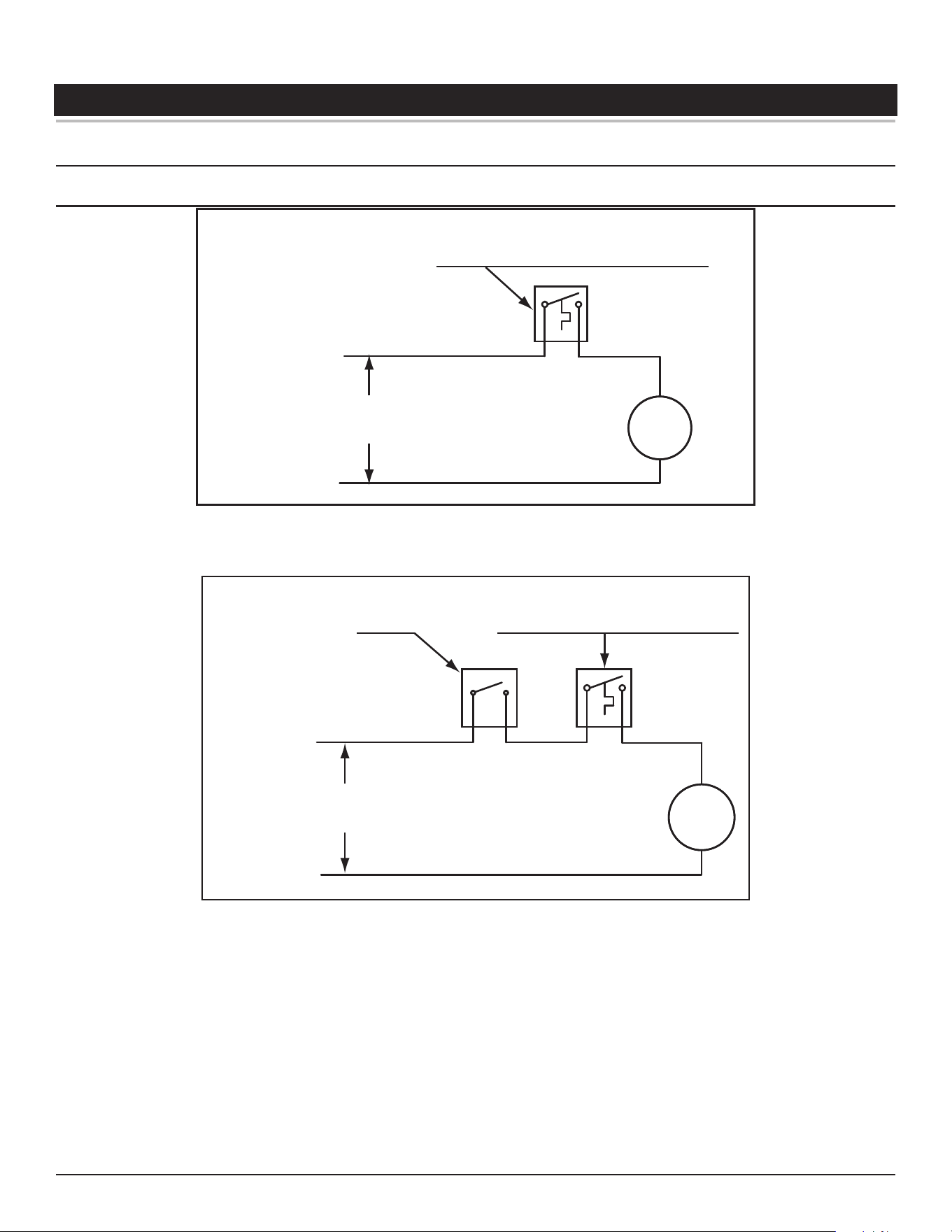
100 • High-Eciency Commercial Gas Water Heaters
DIAGRAMS
WIRING DIAGRAMS
Circulation Pump Wiring Diagrams
FIELD SUPPLIED TEMPERATURE CONTROL
INSTALLED IN THE STORAGE TANK
OR CIRCULATING LOOP RETURN LINE
CIRC
PUMP
MOTOR
L1 HOT
L2 NEUTRAL
120 VAC
POWER
NOTE: USE SEPARATE 120 VAC POWER
SUPPLY FOR PUMP CIRCUIT. DO NOT
SHARE POWER WITH APPLIANCE AS THIS
MAY CAUSE ELECTRICAL LINE NOISE AND
LEAD TO ERRATIC CONTROL SYSTEM
OPERATION.
Figure 72. Circulating Pump Wiring Diagram - Storage Tank or Building Recirculation
FIELD SUPPLIED TEMPERATURE
CONTROL INSTALLED IN THE
CIRCULATING LOOP RETURN LINE
DISHWASHER
TOGGLE
SWITCH
CIRC
PUMP
MOTOR
L1 HOT
L2 NEUTRAL
120 VAC
POWER
NOTE: USE SEPARATE 120 VAC POWER
SUPPLY FOR PUMP CIRCUIT. DO NOT
SHARE POWER WITH APPLIANCE AS THIS
MAY CAUSE ELECTRICAL LINE NOISE AND
LEAD TO ERRATIC CONTROL SYSTEM
OPERATION.
Figure 73. Circulating Pump Wiring Diagram - Dishwasher Loop Toggle Switch
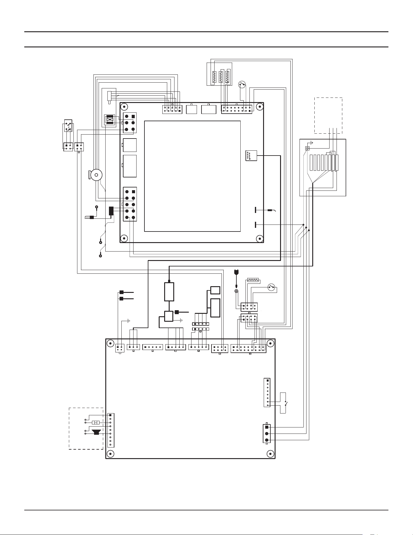
Diagrams
High-Eciency Commercial Gas Water Heaters • 101
Control Circuit Diagrams
J13
J7
43
1 2
3
4
76
5
8 9 10
1
2 3
4
109
65
11
12 13 14
123
45
6
123
67
8
45
9
10
87
15 16
X5
X7
X1
X3
X10
FF2
FF1
Blower Power
Hall Sensor
PWM
GND
24Vdc
L1
N
PE/GND
Gas Valves
Motor Driven
N
L1
Connected to
heater jacket
PE/GND
NTC1
NTC2
Main Temperature Probe
Flame Sensor Rod
Spark XFMR
NTC3
NTC Lower
Connected to
tank
1(L1)
2(N)
3(PE)
1
23
4
10
6 5
11121314
8
7
1516
J6
9
18 17
123
4
6 5
8
7
J8
1
23
45
1
23
45
1
23
45 1
23
1
2
J2
J3
J9
J4
98764 52 31
J5
J10
Enable/Disable Switch
(LDM)
Display 2.0
FMM
KEY
Powered Anode 1 & 2
Alarm
Field Wiring
L1 PE/GNDN
+5V
D+
D-
DGND
+5V
D+
D-
DGND
+5V
D+
D-
DGND
D+
D-
DGND
Outlet Air
Inlet Air
Spark Rod
Connected to
tank PE/GND
Pressure SW
Pressure SW
CPAM
TEMPERATURE
REGULATION CONTROL
(TRC)
COMBUSTION & SAFETY
CONTROL
(CSC)
CPAM
Power Supply
12VDC
NO FACTORY
CONNECTIONS
NO FACTORY
CONNECTIONS
AC Power
120 Vac/60Hz
Junction Box
PE/GND
P1, P2, P3, and P4 ARE NOT USED
P1
P2
P3
P4
P5
P6
P7
P8
OPEN
OPEN
OPEN
OPEN
CPAM N
CPAM L1
L1
N
L1
N
PE/GND
(OAPS)
(IAPS)
PE/GND
PE/GND
L1
N
Leak Detection Module
Powered Anode 3
Connected to tank
PE/GND
Connected to tank
PE/GND
Throttle (MDT)
Blower Command
NO FACTORY
CONNECTIONS
123456
NO FACTORY
CONNECTIONS
NO FACTORY
CONNECTIONS
123
S4962VX1018
Field Wiring
WHITE
BLACK
GREEN
GREEN
GREEN
BLACK
BLACK
WHITE
WHITE
WHITE
WHITE
GREEN
GREEN
GREEN
BLACK
BLACK
BLACK
BLACK
BLACK
BLACK
BLACK
GREEN
WHITE
GREEN
GREEN
WHITE
GREEN
BLUEBLUE
ORANGE
ORANGE
BROWN
BROWN
BLUE
BLUE
W
HITE
WHITE
BLACK
BLACK
GREY
GREY
VIOLET
VIOLET
BLACK
YELLOW
123
4
6 5
8
7
123
4
6 5
8
7
ORANGE
ORANGE
INNER EXT
BLACK
GREEN
BLUE
BLACK
WHITE
WHITE
GREEN
RED
GREEN
BLACK
BLUE
YELLOW
GREEN
WHT/OR
WHT/BR
BLUE
WHT/BL
RED
YELLOW
BLUE
BLACK
BLACK
GREY
VIOLET
RED
YELLOW
GREEN
RED
BLACK
BLUE
WHITE
12
4 3
12
4 3
2A
2
1A
1
WHITE
BLACK
GREEN
RED
1234
1234
RED
YELLOW
BLUE
BLACK
Louvre
8765
2
1
3
4
EXTERNAL ENABLE
DISABLE SWITCH
Figure 74. Wiring Diagram
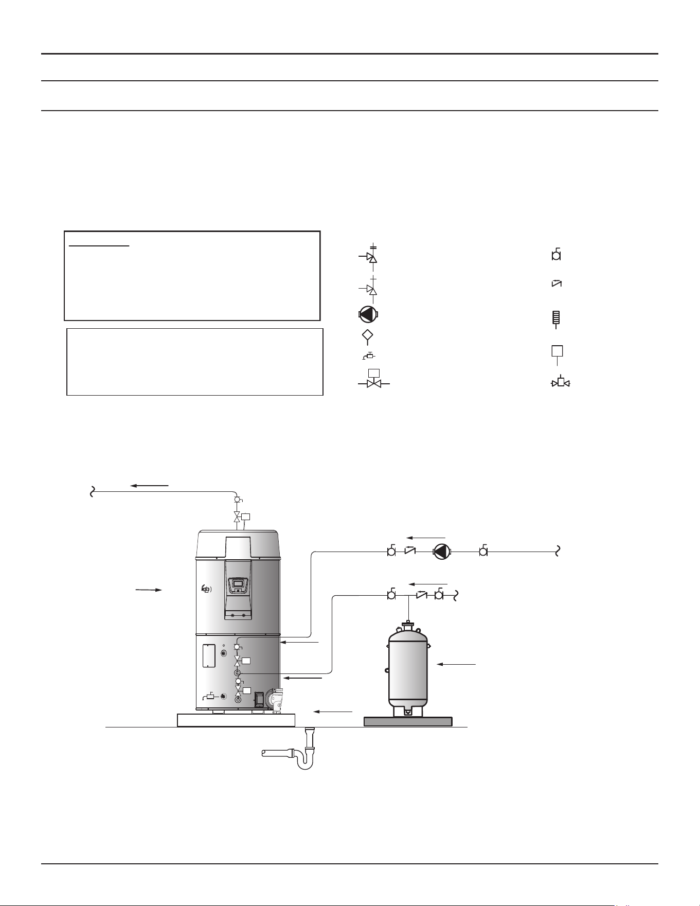
102 • High-Eciency Commercial Gas Water Heaters
Diagrams
PIPING DIAGRAMS
One Water Heater, Single Temperature with Building Recirculation
1. Before installation of water piping review the following:
2. See
Mixing Valves
(page 21).
3. See
Dish-washing Machines
(page 21).
4. See
Temperature-Pressure Relief Valve
(page 22).
5. See
Closed Water Systems
(page 21) and
Thermal Expansion
(page
22).
6. See
Water Line Connections
(page 53).
7. If a pump is being installed between a water heater and storage tank or
on a building recirculation loop wire according to
Figure 72
(page 100).
8. If a pump is being installed in a recirculation loop between the water
heater and a commercial dishwasher wire according to
Figure 73
(page
100).
WARNING: THIS DRAWING SHOWS A
SUGGESTED PIPING CONFIGURATION AND
OTHER DEVICES. CHECK WITH LOCAL CODES
AND ORDINANCES FOR ADDITIONAL
REQUIREMENTS.
ANY MATERIAL, COMPONENT, OR VENDOR
CHANGE MUST HAVE PRIOR APPROVAL BY
THE APPLICABLE PRODUCT ENGINEERING
DEPARTMENT.
LEGEND
Temperature & Pressure Relief Valve
Pressure Relief Valve
Circulang Pump
Tank Temperature Control
Drain Valve
Full-Port Ball Valve
Check Valve
Temperature Gage
Water Flow Switch
Mixing Valve
M
Shut-Off Valve
M
M
M
Expansion Tank
Cold Water
Supply
Finished Floor
Hot Water to
Fixtures
Pipe T&P
Valve to
Open Drain
Floor Drain
Hot Water
Return
NOTES:
1. Preferred piping diagram.
2. The temperature and pressure relief valve setting shall not exceed pressure rating of any component in the system.
3. Service valves are shown for servicing unit. However, local codes shall govern their usage.
4. Ensure that any installed recirculation system does not bypass or interfere in any way with shut-off valves.
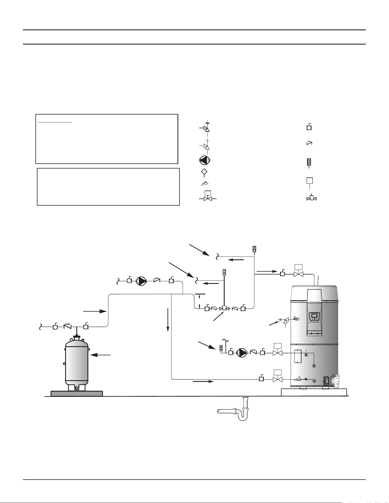
Diagrams
High-Eciency Commercial Gas Water Heaters • 103
One Water Heater, Two Temperatures with High-Temperature Loop Recirculation with Building Recirculation
Before installation of water piping review the following:
1. See
Mixing Valves
(page 21).
2. See
Dish-washing Machines
(page 21).
3. See
Temperature-Pressure Relief Valve
(page 22).
4. See
Closed Water Systems
(page 21) and
Thermal Expansion
(page
22).
5. See
Water Line Connections
(page 53).
6. If a pump is being installed between a water heater and storage tank or
on a building recirculation loop wire according to
Figure 72
(page 100).
7. If a pump is being installed in a recirculation loop between the water
heater and a commercial dishwasher wire according to
Figure 73
(page
100).
WARNING: THIS DRAWING SHOWS A
SUGGESTED PIPING CONFIGURATION AND
OTHER DEVICES. CHECK WITH LOCAL CODES
AND ORDINANCES FOR ADDITIONAL
REQUIREMENTS.
ANY MATERIAL, COMPONENT, OR VENDOR
CHANGE MUST HAVE PRIOR APPROVAL BY
THE APPLICABLE PRODUCT ENGINEERING
DEPARTMENT.
LEGEND
Temperature & Pressure Relief Valve
Pressure Relief Valve
Circulang Pump
Tank Temperature Control
Drain Valve
Full-Port Ball Valve
Check Valve
Temperature Gage
Water Flow Switch
Mixing Valve
M
Shut-Off Valve
12”to 15”
Mixing Valve
M
M
M
Cold
Pipe T&P to
Open Drain
Outlet
Tempered
Water Outlet
Tempered
Water
Return
Cold Water
Supply
Expansion Tank
Finished Floor
Floor Drain
Hot Water
Return
NOTES:
1. Preferred piping diagram.
2. The temperature and pressure relief valve setting shall not exceed pressure rating of any component in the system.
3. Service valves are shown for servicing unit. However, local codes shall govern their usage.
4. Ensure that any installed recirculation system does not bypass or interfere in any way with shut-off valves.
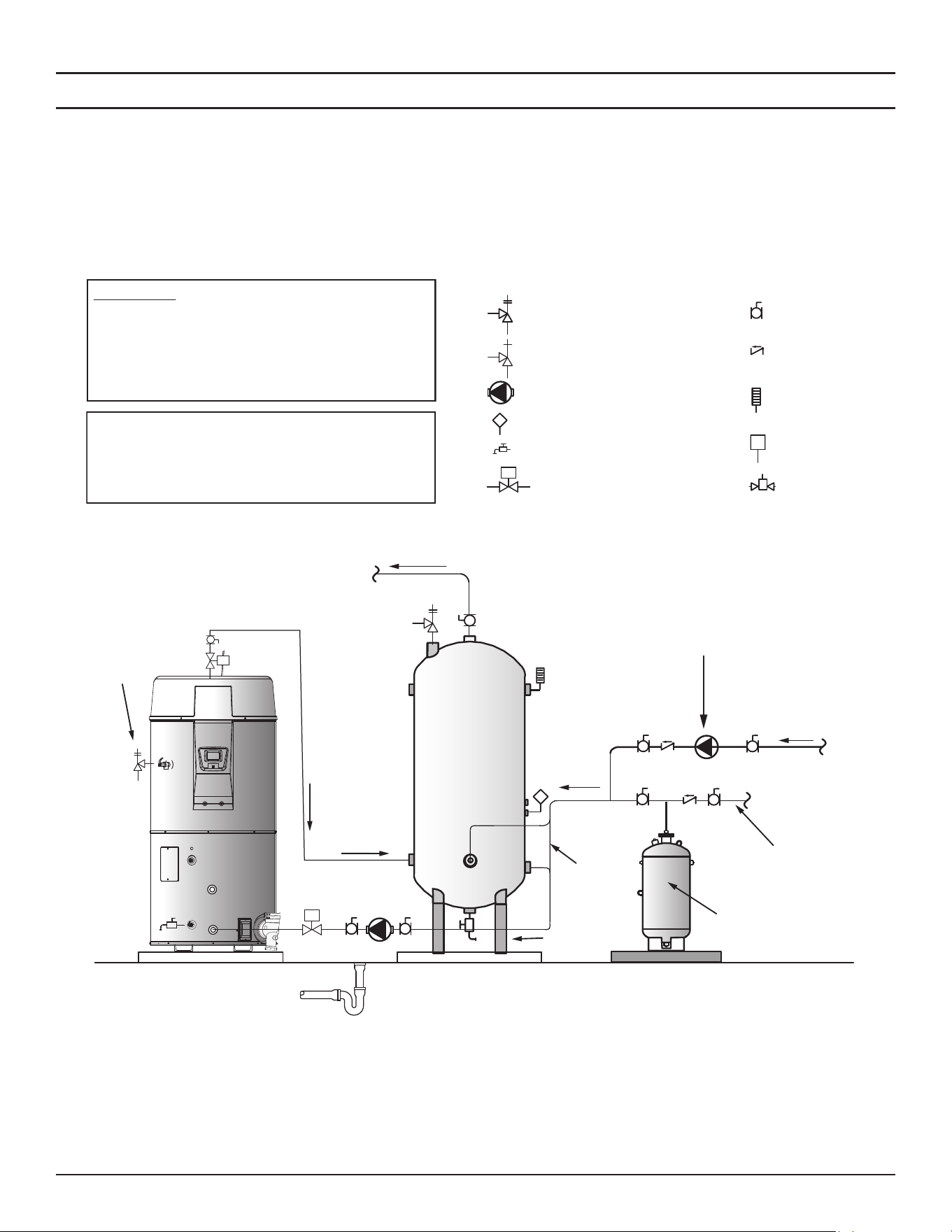
104 • High-Eciency Commercial Gas Water Heaters
Diagrams
One Water Heater, Single Temperature with Vertical Storage Tank Forced Recirculation with Building Recirculation
Before installation of water piping review the following:
1. See
Mixing Valves
(page 21).
2. See
Dish-washing Machines
(page 21).
3. See
Temperature-Pressure Relief Valve
(page 22).
4. See
Closed Water Systems
(page 21) and
Thermal Expansion
(page
22).
5. See
Water Line Connections
(page 53).
6. If a pump is being installed between a water heater and storage tank or
on a building recirculation loop wire according to
Figure 72
(page 100).
7. If a pump is being installed in a recirculation loop between the water
heater and a commercial dishwasher wire according to
Figure 73
(page
100).
WARNING: THIS DRAWING SHOWS A
SUGGESTED PIPING CONFIGURATION AND
OTHER DEVICES. CHECK WITH LOCAL CODES
AND ORDINANCES FOR ADDITIONAL
REQUIREMENTS.
ANY MATERIAL, COMPONENT, OR VENDOR
CHANGE MUST HAVE PRIOR APPROVAL BY
THE APPLICABLE PRODUCT ENGINEERING
DEPARTMENT.
LEGEND
Temperature & Pressure Relief Valve
Pressure Relief Valve
Circulang Pump
Tank Temperature Control
Drain Valve
Full-Port Ball Valve
Check Valve
Temperature Gage
Water Flow Switch
Mixing Valve
M
Shut-Off Valve
STORAGE TANK
M
M
Finished Floor
Hot Water to
Fixtures
Pipe
T&P
Valve to
Open
Drain
Expansion Tank
Cold Water
Supply
Hot Water
Return
From
Fixtures
Alternate Cold
Water
Connecon
Floor Drain
Circulang
Pump
NOTES:
1. Preferred piping diagram.
2. The temperature and pressure relief valve setting shall not exceed pressure rating of any component in the system.
3. Service valves are shown for servicing unit. However, local codes shall govern their usage.
4. The tank temperature control should be wired to and control the pump between the water heater(s) and the storage tank(s).
5. The water heater’s operating thermostat should be set 5 degrees F higher than the tank temperature control.
6. Ensure that any installed recirculation system does not bypass or interfere in any way with shut-off valves.
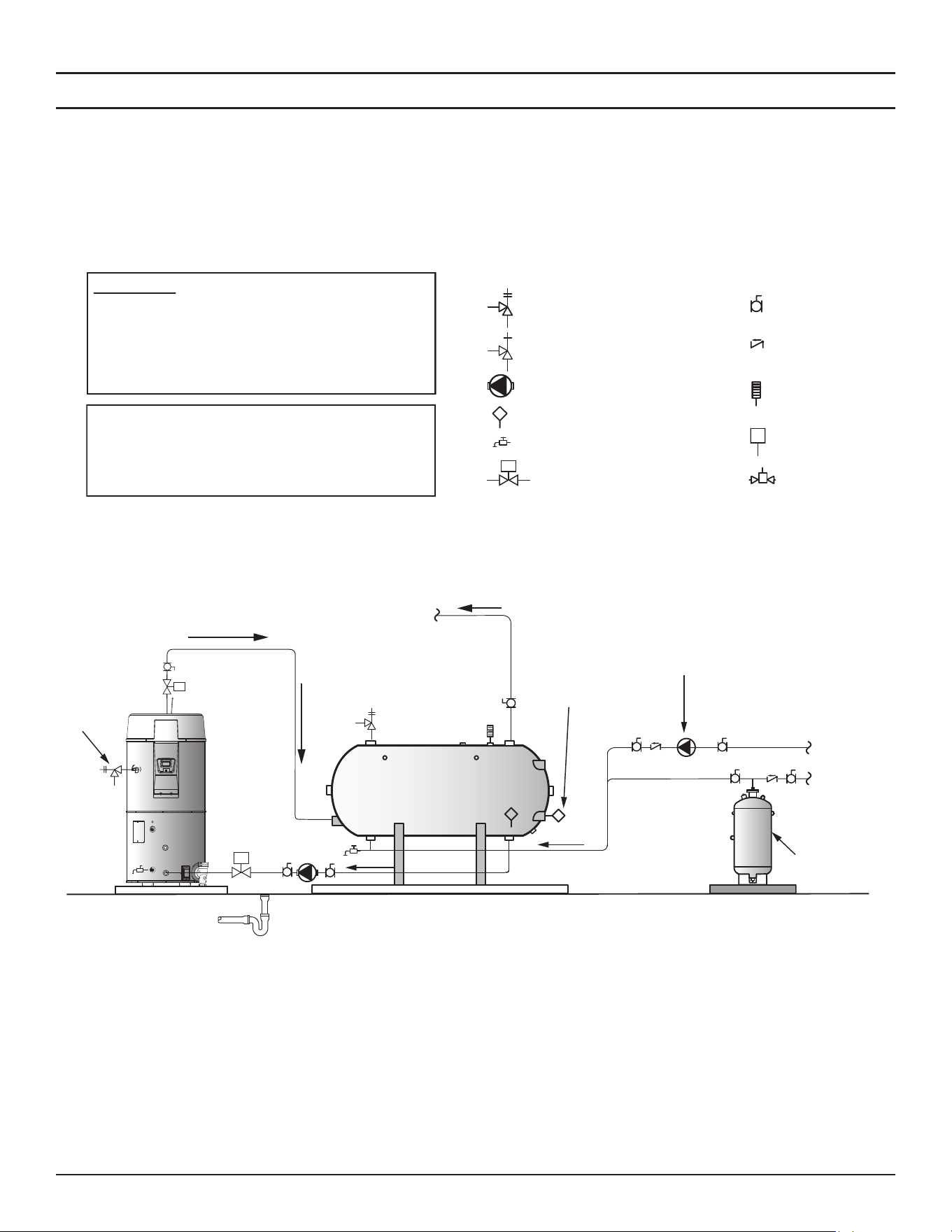
Diagrams
High-Eciency Commercial Gas Water Heaters • 105
One Water Heater, Single Temperature with Horizontal Storage Tank, Forced Recirculation with Building Recirculation
Before installation of water piping review the following:
1. See
Mixing Valves
(page 21).
2. See
Dish-washing Machines
(page 21).
3.
See Temperature-Pressure Relief Valve
(page 22).
4. See
Closed Water Systems
(page 21) and
Thermal Expansion
(page
22).
5. See
Water Line Connections
(page 53).
6. If a pump is being installed between a water heater and storage tank or
on a building recirculation loop wire according to
Figure 72
(page 100).
7. If a pump is being installed in a recirculation loop between the water
heater and a commercial dishwasher wire according to
Figure 73
(page
100).
WARNING: THIS DRAWING SHOWS A
SUGGESTED PIPING CONFIGURATION AND
OTHER DEVICES. CHECK WITH LOCAL CODES
AND ORDINANCES FOR ADDITIONAL
REQUIREMENTS.
ANY MATERIAL, COMPONENT, OR VENDOR
CHANGE MUST HAVE PRIOR APPROVAL BY
THE APPLICABLE PRODUCT ENGINEERING
DEPARTMENT.
LEGEND
Temperature & Pressure Relief Valve
Pressure Relief Valve
Circulang Pump
Tank Temperature Control
Drain Valve
Full-Port Ball Valve
Check Valve
Temperature Gage
Water Flow Switch
Mixing Valve
M
Shut-Off Valve
STORAGE TANK
M
M
Finished Floor
Hot Water to
Fixtures
Pipe T&P
Valve to Open
Drain
Expansion Tank
Cold Water Supply
Hot Water Return
Alternate Cold Water
Connecon
Floor Drain
Circulang
Pump
NOTES:
1. Preferred piping diagram.
2. The temperature and pressure relief valve setting shall not exceed pressure rating of any component in the system.
3. Service valves are shown for servicing unit. However, local codes shall govern their usage.
4. The tank temperature control should be wired to and control the pump between the water heater(s) and the storage tank(s).
5. The water heater’s operating thermostat should be set 5 degrees F higher than the tank temperature control.
6. Ensure that any installed recirculation system does not bypass or interfere in any way with shut-off valves.
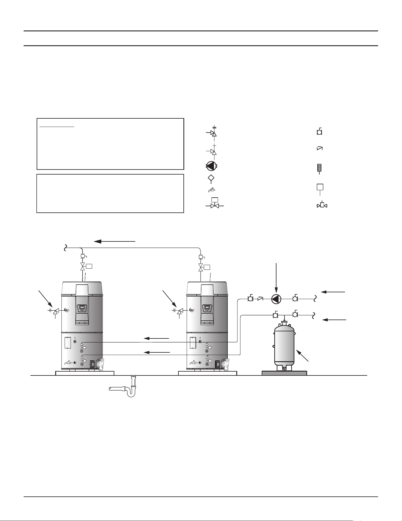
106 • High-Eciency Commercial Gas Water Heaters
Diagrams
Two Water Heaters, Single Temperature with Building Recirculation
Before installation of water piping review the following:
1. See
Mixing Valves
(page 21).
2. See
Dish-washing Machines
(page 21).
3. See
Temperature-Pressure Relief Valve
(page 22).
4. See
Closed Water Systems
(page 21) and
Thermal Expansion
(page
22).
5. See
Water Line Connections
(page 53).
6. If a pump is being installed between a water heater and storage tank or
on a building recirculation loop, wire according to
Figure 72
(page 100).
7. If a pump is being installed in a recirculation loop between the water
heater and a commercial dishwasher wire according to
Figure 73
(page
100).
WARNING: THIS DRAWING SHOWS A
SUGGESTED PIPING CONFIGURATION AND
OTHER DEVICES. CHECK WITH LOCAL CODES
AND ORDINANCES FOR ADDITIONAL
REQUIREMENTS.
ANY MATERIAL, COMPONENT, OR VENDOR
CHANGE MUST HAVE PRIOR APPROVAL BY
THE APPLICABLE PRODUCT ENGINEERING
DEPARTMENT.
LEGEND
Temperature & Pressure Relief Valve
Pressure Relief Valve
Circulang Pump
Tank Temperature Control
Drain Valve
Full-Port Ball Valve
Check Valve
Temperature Gage
Water Flow Switch
Mixing Valve
M
Shut-Off Valve
M
M
M
M
M
M
Finished Floor
Hot Water
to Fixtures
Pipe T&P
Valve to Open
Drain
Expansion Tank
Cold Water Supply
Hot Water Return
Floor Drain
Circulang
Pump
Pipe T&P
Valve to Open
Drain
NOTES:
1. Preferred piping diagram.
2. The temperature and pressure relief valve setting shall not exceed pressure rating of any component in the system.
3. Service valves are shown for servicing unit. However, local codes shall govern their usage.
4. Ensure that any installed recirculation system does not bypass or interfere in any way with shut-off valves.
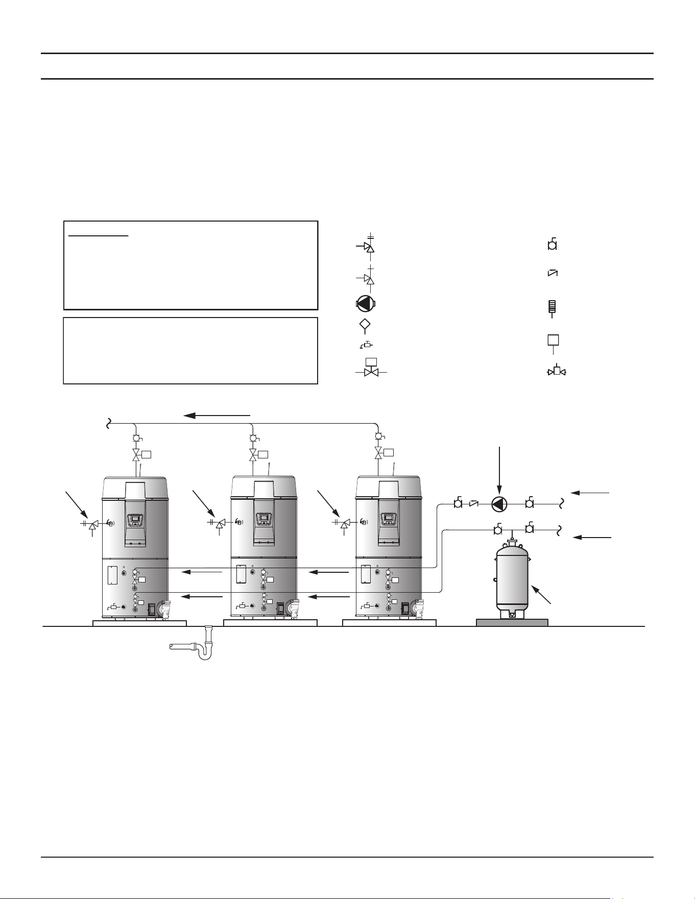
Diagrams
High-Eciency Commercial Gas Water Heaters • 107
Three Water Heaters, Single Temperature with Building Recirculation
Before installation of water piping review the following:
1. See
Mixing Valves
(page 21).
2. See
Dish-washing Machines
(page 21).
3. See
Temperature-Pressure Relief Valve
(page 22).
4. See
Closed Water Systems
(page 21) and
Thermal Expansion
(page
22).
5. See
Water Line Connections
(page 53).
6. If a pump is being installed between a water heater and storage tank or
on a building recirculation loop wire according to
Figure 72
(page 100).
7. If a pump is being installed in a recirculation loop between the water
heater and a commercial dishwasher wire according to
Figure 73
(page
100).
WARNING: THIS DRAWING SHOWS A
SUGGESTED PIPING CONFIGURATION AND
OTHER DEVICES. CHECK WITH LOCAL CODES
AND ORDINANCES FOR ADDITIONAL
REQUIREMENTS.
ANY MATERIAL, COMPONENT, OR VENDOR
CHANGE MUST HAVE PRIOR APPROVAL BY
THE APPLICABLE PRODUCT ENGINEERING
DEPARTMENT.
LEGEND
Temperature & Pressure Relief Valve
Pressure Relief Valve
Circulang Pump
Tank Temperature Control
Drain Valve
Full-Port Ball Valve
Check Valve
Temperature Gage
Water Flow Switch
Mixing Valve
M
Shut-Off Valve
M M
M
M
M
M
M
M
M
Finished Floor
Hot Water
to Fixtures
Pipe T&P
Valve to Open
Drain
Expansion Tank
Cold Water Supply
Hot Water Return
Floor Drain
Circulang
Pump
Pipe T&P
Valve to Open
Drain
Pipe T&P
Valve to Open
Drain
NOTES:
1. Preferred piping diagram.
2. The temperature and pressure relief valve setting shall not exceed pressure rating of any component in the system.
3. Service valves are shown for servicing unit. However, local codes shall govern their usage.
4. Ensure that any installed recirculation system does not bypass or interfere in any way with shut-off valves.
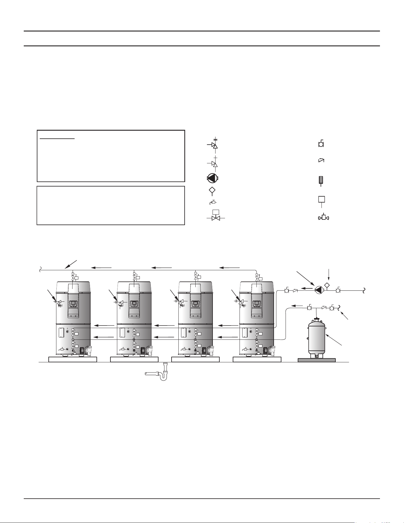
108 • High-Eciency Commercial Gas Water Heaters
Diagrams
Four Water Heaters, Single Temperature with Building Recirculation
Before installation of water piping review the following:
1. See
Mixing Valves
(page 21).
2. See
Dish-washing Machines
(page 21).
3. See
Temperature-Pressure Relief Valve
(page 22).
4. See
Closed Water Systems
(page 21) and
Thermal Expansion
(page
22).
5. See
Water Line Connections
(page 53).
6. If a pump is being installed between a water heater and storage tank or
on a building recirculation loop wire according to
Figure 72
(page 100).
7. If a pump is being installed in a recirculation loop between the water
heater and a commercial dishwasher wire according to
Figure 73
(page
100).
WARNING: THIS DRAWING SHOWS A
SUGGESTED PIPING CONFIGURATION AND
OTHER DEVICES. CHECK WITH LOCAL CODES
AND ORDINANCES FOR ADDITIONAL
REQUIREMENTS.
ANY MATERIAL, COMPONENT, OR VENDOR
CHANGE MUST HAVE PRIOR APPROVAL BY
THE APPLICABLE PRODUCT ENGINEERING
DEPARTMENT.
LEGEND
Temperature & Pressure Relief Valve
Pressure Relief Valve
Circulang Pump
Tank Temperature Control
Drain Valve
Full-Port Ball Valve
Check Valve
Temperature Gage
Water Flow Switch
Mixing Valve
M
Shut-Off Valve
Hot Water
To Fixtures
Tank Temperature
Control
Pipe T&P To
Open Drain
Pipe T&P To
Open Drain
Pipe T&P To
Open Drain
Pipe T&P To
Open Drain
Cold Water
Supply
Expansion
Tank
Hot Water
Return
Floor Drain
Finished Floor
Circulating
Pump
M
M
M
M
M
M
M
M
M
M
M
M
NOTES:
1. Preferred piping diagram.
2. The temperature and pressure relief valve setting shall not exceed pressure rating of any component in the system.
3. Service valves are shown for servicing unit. However, local codes shall govern their usage.
4. Ensure that any installed recirculation system does not bypass or interfere in any way with shut-off valves.

High-Eciency Commercial Gas Water Heaters • 109
NOTES

110 • High-Eciency Commercial Gas Water Heaters
NOTES

High-Eciency Commercial Gas Water Heaters • 111
NOTES

Copyright © 2025. All rights reserved.