MP4010-2503
1
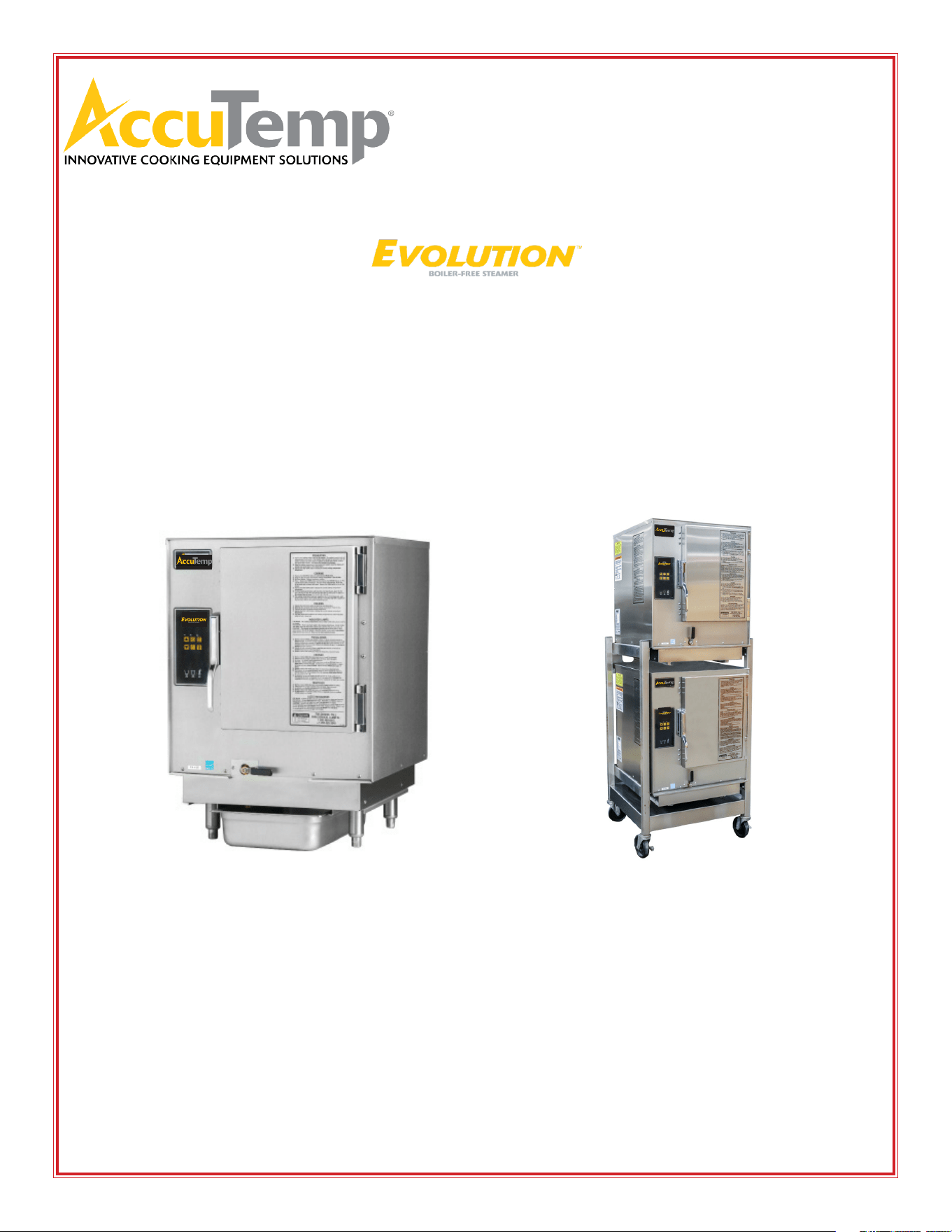
EVOLUTION GAS STEAMER
INSTALLATION & OPERATOR MANUAL
These installation instructions have been prepared for qualied gas and
electric equipment installation personnel, who should perform the installation,
initial eld start-up and complete the equipment adjustments described in this
manual.
IMPORTANT WARRANTY INFORMATION
WARRANTY REGISTRATION - STARTUP FORM INSIDE THIS MANUAL MUST BE REMOVED,
COMPLETED, SIGNED BY CUSTOMER AND A COPY EMAILED, FAXED OR MAILED BACK TO
ACTIVATE THE LIMITED WARRANTY.
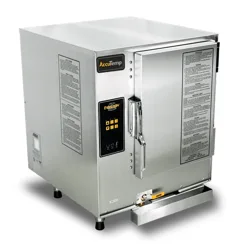
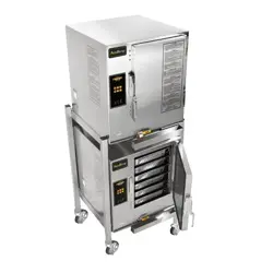
Customer Supplied
Connection-Less Model Connected Model Double Stack

MP4010-2503
2
The State of California enacted the California Safe Drinking Water and Toxic
Enforcement Act of 1986, (Prop. 65), which “prohibits any person in the course
of doing business from knowingly and intentionally exposing any individual to
a chemical known to the State of California to cause cancer or reproductive
toxicity without rst giving clear and reasonable warning to such individuals.”
The Governor’s Scientic Advisory Panel added Carbon Monoxide to the list of
hazardous chemicals known to cause reproductive harm.
In order to establish full compliance with Proposition 65, a yellow warning label has
been attached to each gas red unit manufactured by AccuTemp Products,Inc.
Carbon monoxide would not be present in concentrations that would pose a
“signicant risk” to the consumer when the equipment is installed, operated and
maintained as follows:
1. Installed in accordance with all local codes, or in the absence of local codes,
with the current National Fuel Gas Code Z223.1, latest addenda.
2. Installed under a properly designed and operating exhaust hood.
3. Connected to the type of gas for which the unit is equipped.
4. Proper appliance pressure regulator installed on the gas supply line and adjusted
for the manifold pressure marked on the rating plate.
5. Adequate air supply to the unit and adequate clearance around the ue.
6. The equipment is operated in the manner intended using the proper utensil for
that type of appliance.
7. Keep the equipment clean and have it checked periodically.
8. Burner air adjustments, mechanical maintenance and repairs should be
performed by qualied service personnel.
WARNING
MP4010-2503
1
TABLE OF CONTENTS
SAFETY WARNINGS INFORMATION PAGE 2
START UP FORM PAGE 3
GENERAL INFORMATION PAGE 5
INSTALLATION PAGE 7
OPERATION - USE PAGE 16
OPERATION - CLEANING PAGE 20
TROUBLESHOOTING PAGE 22
SERVICE PAGE 23
PREVENTATIVE MAINTENANCE CHECKLIST PAGE 24
WARRANTY PAGE 25
DOCUMENT HISTORY
CURRENT
REVISION
DATE CHANGE
2503 3/11/2025 Added Installation Note - Page 7 Sec 3.4
2501 1/13/2025 Revised Start up Checklist
2411 11/13/2024 Consolidated the cleaning to match equipment label
2311 11/09/2023 Instructions added on installation of new condensate rail.
Added Programming instructions for new control revision 01
2302 02/20/2023 Adjusted NG gas pressure.
1809 09/05/2018 Review and update of manual

MP4010-2503
2
The safety instructions listed below on this page should be posted in a
prominent location as a reminder of safe practices as well as recommended
actions to follow in the event of an equipment or facility utility issue.
In the event a gas odor is detected, shut down all appliances at the main gas shut-o valve
and contact the local gas company or gas supplier service.
IMPORTANT FOR YOUR SAFETY
WARNING
In the event of a power failure, do not attempt to operate this appliance.
Do not store or use gasoline or other ammable vapors or liquids in the vicinity of this or
any other appliance.
Improper installation, adjustment, alteration, service or maintenance can cause property
damage, injury or death. Read the installation, operating, and maintenance instructions
thoroughly before installing or servicing this equipment.
Only qualied service technicians/electricians should install this appliance to ensure that all
electrical and safety requirements are met and that all wiring is installed in accordance with
all national, state and local electrical codes.
WARNING
WARNING
WARNING
WARNING
MP4010-2503
3
• For proper installation, please refer to the installation and owner’s manual, which includes step-by-step
instructions and a start-up checklist.
• AccuTemp Products, Inc. is not responsible for the installation process, and we do not recommend
modications to the electrical supply. Any in-eld modications made without written authorization
from AccuTemp Products, Inc. will void all warranties.
• It is recommended that the wall receptacle be placed as low as state and local codes allow. Placing
the receptacle in high heat zones, such as directly above, below, or beside the exhaust ue, may cause
service issues not covered by the product warranty.
• If your installation site is at an altitude greater than 4,000 feet above sea level, please contact the
AccuTemp Technical Services Department to conrm the appropriate orice size for the main burners.
• An external regulator should only be used if the supply gas pressure exceeds 0.5 psig / 14” WC.
SERIAL NUMBER:
MODEL NUMBER:
This checklist must be completed accurately and in full. To activate warranty, please submit this form to AccuTemp
Warranty Department @ warranty@accutemp.net.
EVOLUTION Gas Steamer Start Up Checklist
1. Is the steamer being installed at an altitude greater than 4,000 feet? (Circle Y/N) Y N
2. Is the supply gas pressure above 0.5 psig/14”wc? (Circle Y/N) Y N
3. Is an external gas regulator connected to the steamer? (Circle Y/N) Y N
4. Is the steamer level? (Circle Y/N) Y N
5. If the steamer has legs, have the (4) rubber foot tips been installed? (Circle Y/N) Y N
6. Is the steamer hard connected to the gas supply line? (Circle Y/N) Y N
7. If the steamer is connected with a 3/4” exible commercial grade gas hose? (Circle
Y/N)
Y N
8. If yes, is a restraining device used? (Circle Y/N) Y N
YES
NO
Location Name:
Street Address:
City:
State/ Zip Code:
Building Name/#:
Contact Name:
Phone:
Email:
Date:
Service Company:
Street Address:
State/ Zip Code:
Service Phone #:
Technicians Name:
Technicians Email:
Additional Info:
MP4010-2503
4
EVOLUTION Gas Steamer Start Up Checklist (continued)
YES NO
1. What is the Lenth and Width of the Gas Supply Line L W
2. Gas Pressure measurements
Natural Gas: Supply WC Manifold WC (Manifold should be 3.5WC)
Dynamic pressure should be 3.5”WC (Regulator valve pressure tap - 1/8NPT)
Propane: Supply WC Manifold WC (Manifold should be 10WC)
Dynamic pressure should be 10”WC (Regulator valve pressure tap -1/8NPT)
3. What is the measured ame sense on the unit? uA (microampere)
4. At what mark is the Blower Motor air shutter set to?
5. Is the supply water pressure lower than 30PSI (Circle Y/N) Y N
6. With the Steam Collector Pan removed and the Steam Chamber empty, does the
Auto-Fill Water Stream hit the chamber oor half-way to three-quarters of the way
towards the opposite wall?
Note: If the Auto-Fill Water Stream is slamming against the opposite wall, then the water pressure is too
high and will need to be adjusted at the supply water shut-o valve, to the above parameters.
Y N
7. Is the Float Ball Installed in the unit? Y N
8. Is there a High Water alarm when the Float Ball is removed? Y N
Connected Models Only
9. Does the Low Water Light and Alarm turn OFF once the chamber water level has
reached the middle of the Low Water Sensor? (Connected Water Models will only have the
Low Water Light and no Alarm.) (Circle Y/N)
Y N
10. Has additional piping been added to the steam vent? (Circle Y/N) Y N
11. Does the steamer operate when all gas appliance in the kitchen are operating?
(Circle Y/N)
Y N
12. Verify the water temperature in COOK MODE (COO on digital display) °F
13. Does the unit cycle the heat once it is in COOK MODE? (Circle Y/N) Y N
14. Is there any added drain hose/piping attached to the Steamer Drain System? Note:
Does the added drain hose/piping to the steamer meet the specications listed on
the instruction label attached to the back of the steamer? (Circle Y/N)
Y N
15. Take photographs of install, including: Front of steamer, Side view of steamer, Gas
hook up, supply and ID Tag.
I accept this checklist as complete and accurate:
Signed: Restaurant Management
Print Name:
Date: / /
AccuTemp Products, Inc.
19119 John Adams Drive
New Haven IN 46774
Email: warranty@accutemp.net
Phone: 260.469.3040 or 800.480.0415
Fax: 260.493.8914
ALL Models

MP4010-2503
5
1. GENERAL INFORMATION
AccuTemp appreciates your decision to purchase our equipment.
Your new equipment combines the long-term experience of
the best chefs together with the latest scientic and modern
technologies. With the help of your new equipment, you shall
always achieve the highest quality dishes and a superior product.
To ensure that you succeed right from the beginning in gaining the
best results, we would like to provide you, through this manual,
with all the information necessary for smooth operation.
AccuTemp guarantees proper functioning and high-quality
service.
We oer:
• 12-month guarantee of awless operation of the equipment.
• Warranty service and post-warranty support.
• Technical and advisory services in connection with servicing
and maintenance.
• Chef expert advisory service.
We hope that you enjoy working with AccuTemp equipment and
that you always have many satised guests.
This manual contains available information on the AccuTemp
equipment accessible at the time of publication of this
manual. Errors and technical modications are under the
usual provision.
1.1 Contact
Should you have any questions we are at your service at the
following telephone numbers and addresses.
AccuTemp Products
11919 John Adams Drive
Fort Wayne, IN 46774
Tel: 800.480.0415
Fax: 260.469.3045
E-Mail: service@accutemp.net
1.2 Use of the operating instructions
Read carefully and follow the instructions for operation and
maintenance of your equipment. Should some of the procedures
be unclear, contact your salesperson for further assistance.
SYMBOLS USED
The symbols used here draw attention to activities that may
inuence safety, health protection and the necessity for servicing.
They help you to prevent problems and the advice will make your
work easier.
WARNING
Indicates a potentially hazardous situation; which, if unchanged,
will result in death or serious injury.
CAUTION
Indicates a potentially hazardous situation; which, if
unchanged, will result in minor or moderate injury
NOTE
Advises reader of information or instructions vital to the
operation or maintenance of the equipment
EARTH GROUND
DANGEROUS VOLTAGE
HOT SURFACE
1.3 Warranty Restrictions
All the technical information, data, operation and maintenance
instructions contained in this operating manual correspond to the
nal state upon delivery and were compiled with regard to our pre-
vious experience and to our best knowledge. We reserve the right
to carry out technical changes on the equipment described in this
operating manual as part of further development of the equipment.
We do not accept any responsibility for any damage or failures
arising from incorrect operation, lack of attention to this
manual, use of aggressive chemical cleaning products and
technically incorrect repairs. We call your attention to the fact
that this also applies to spare parts not delivered by us and
to accessory equipment not pre-tested and approved by us.
All modications or changes made to the equipment through
your own eorts are not permitted for the reasons of safety
and relieves AccuTemp of any responsibility for damage arising
there from. Within the scope of the warranty obligations
negotiated in the contract under the exclusion of further claims,
we accept responsibility for accidental mistakes or neglects.
Claims for reimbursement for damages are not possible regardless
of upon what judicial reason such claim is made.
MP4010-2503
6
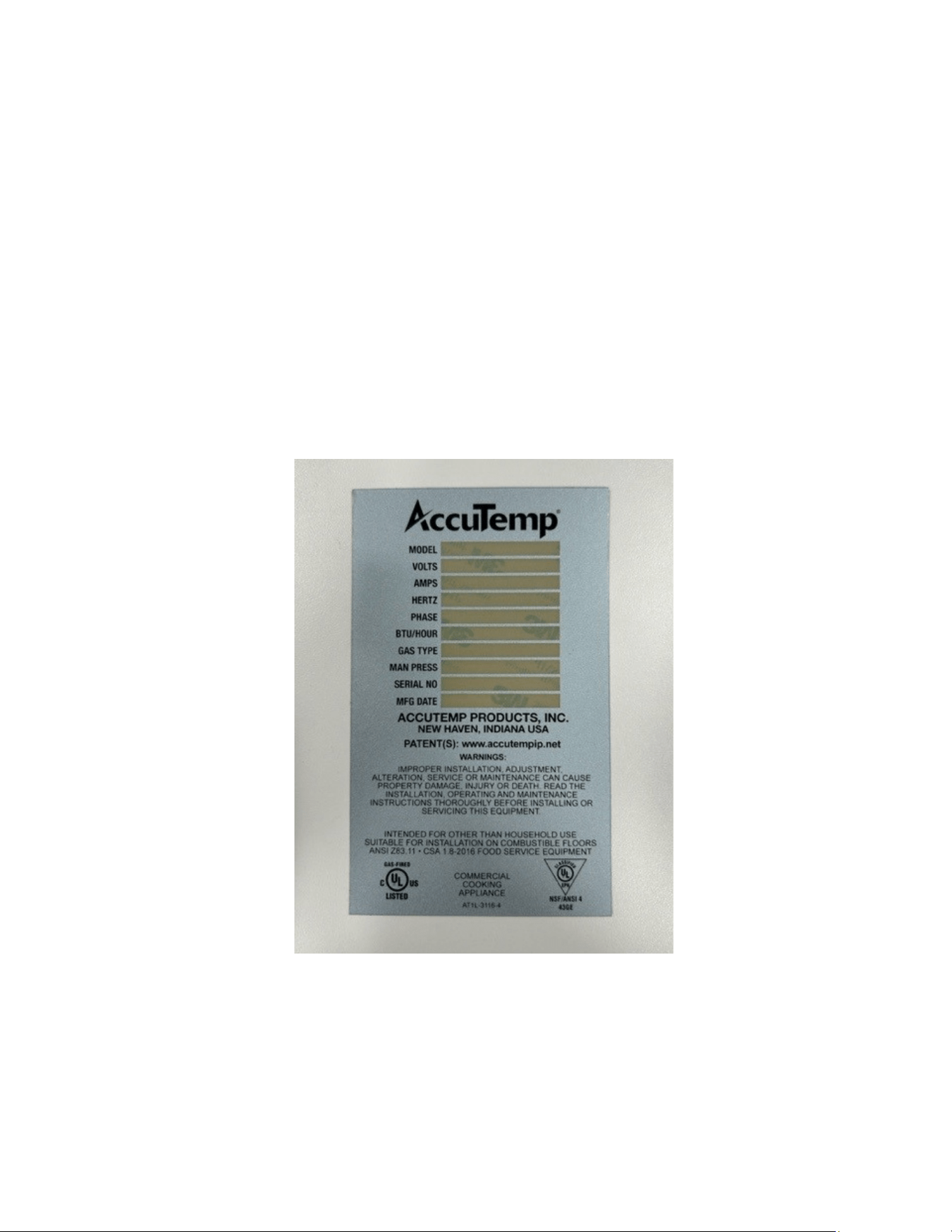
2. EQUIPMENT DATA PLATE
2.1 Labeling
Model: A B CCC D E FFF G H I J K
Where:
A is the base model N = Natural Gas, P = Propane
B is the size of the unit: 6 pan
CCC is the supply Voltage
D is the number of phases: 1 or 3
E is the control series D=Manual Fill, E=Autoll
F is the energy input
G is the timer conguration
H is the thermostat conguration
I is the door conguration
J is the leg conguration
K is the HDW conguration
MP4010-2503
7
3.1 Installation Notice
Only qualied service technicians/electricians should perform
the installation to ensure that all electrical, gas and safety
requirements are met and that all wiring, gas and plumbing
installations are performed in accordance with all national, state
and local codes.
The installation must conform with local codes, or in the
absence of local codes, with the National Fuel Gas Code, ANSA/
NFPA 54, or the Natural Gas and Propane Installation Code, CSA
B149.1 as applicable.
The appliance and its individual shuto must be disconnected
from the gas supply piping system during any pressure testing of
that system at test pressures in excess of 1/2 PSI(3.5kPA)
LOCATION COMBUSTIBLE NONCOMBUSTIBLE
SIDES
1” 0”
REAR
2” 0”
FIGURE 1: EQUIPMENT CLEARANCE INFORMATION
3.2 Unpacking
This appliance was carefully inspected before shipment from the
factory. The transportation company assumes full responsibility
for safe delivery to the customer until customer acceptance
of the package. Careful inspection of the packaging and the
appliance should be completed before acceptance from the
transportation company.
3.3 Steamer Lifting
Steamers are heavy enough to require additional manpower or
powered assistance when installing or moving the steamer.
When moving the equipment manually make sure there are
enough people for the task as the equipment is heavy.
Make sure the equipment is not dropped during moving.
People doing the carrying could be seriously injured and/or the
equipment damaged. The manufacturer does not accept any
responsibility for damage resulted from such actions.
3 INSTALLATION
3.4 Location and Placement
The AccuTemp Evolution gas steamer can be placed on a
commercial kitchen counter-top or installed on a AccuTemp
Evolution gas steamer stand. Provisions should be incorporated
in the kitchen to ensure an adequate supply of fresh air for
proper combustion and ventilation (FIGURE 1).
The steamer must be installed in a level condition. An out of level
condition may cause erratic operation and damage to the steamer.
Damage of this kind is not covered by the limited warranty. Use a spirit
level resting on the top surface of the steamer to ensure it is level front
to back and left to right.
AccuTemp steamers can be placed on a commercial kitchen
counter-top or installed on an AccuTemp steamer stand. Do not place
directly onto any kind of heat source
For the correct operation of the steamer it is important that
it is leveled in a horizontal position.
Placement on an unlevel or uneven surface may result in
performance faults. Only professional installation of the device
guarantees it high-quality operation.
Check proper setting of the equipment by placing a hotel
pan lled with water inside the steamer and observing the water
level.
A minimum clearance of 10 inches must be allowed for
on the left hand side of the unit for maintenance access to the
unit. Failure to provide this may limit the eectiveness of service
dispatch and incur additional costs not covered by warranty.
Counter Top Placement
In a counter top installation the steamer can be leveled using
the adjustable legs. Once this is complete it is required that the
supplied (4) rubber foot tips be installed to keep the steamer
from possibly sliding on the counter top under normal use.
3.5 Stand Installation
If an AccuTemp Evolution Gas Steamer Stand is used ensure the
oor is level and place the two locking casters to the “ON” posi-
tion.
All AccuTemp Evolution Gas Steamer Stand with casters, shall
be made with a connector that complies with the Standard for
Connectors for Movable Gas Appliances, ANSI Z21.69 or CAN/
CGA 6.16 and a quick disconnect device that complies with the
Standard for Quick Disconnect Devices for Use with Gas Fuel,
ANSI Z21.41 or CAN1-6.9.
When using a stand that is equipped with casters, the oor
surface must be level and at. Failure to do so can result in a
“tipping” hazard that could result in serious injury.
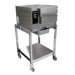
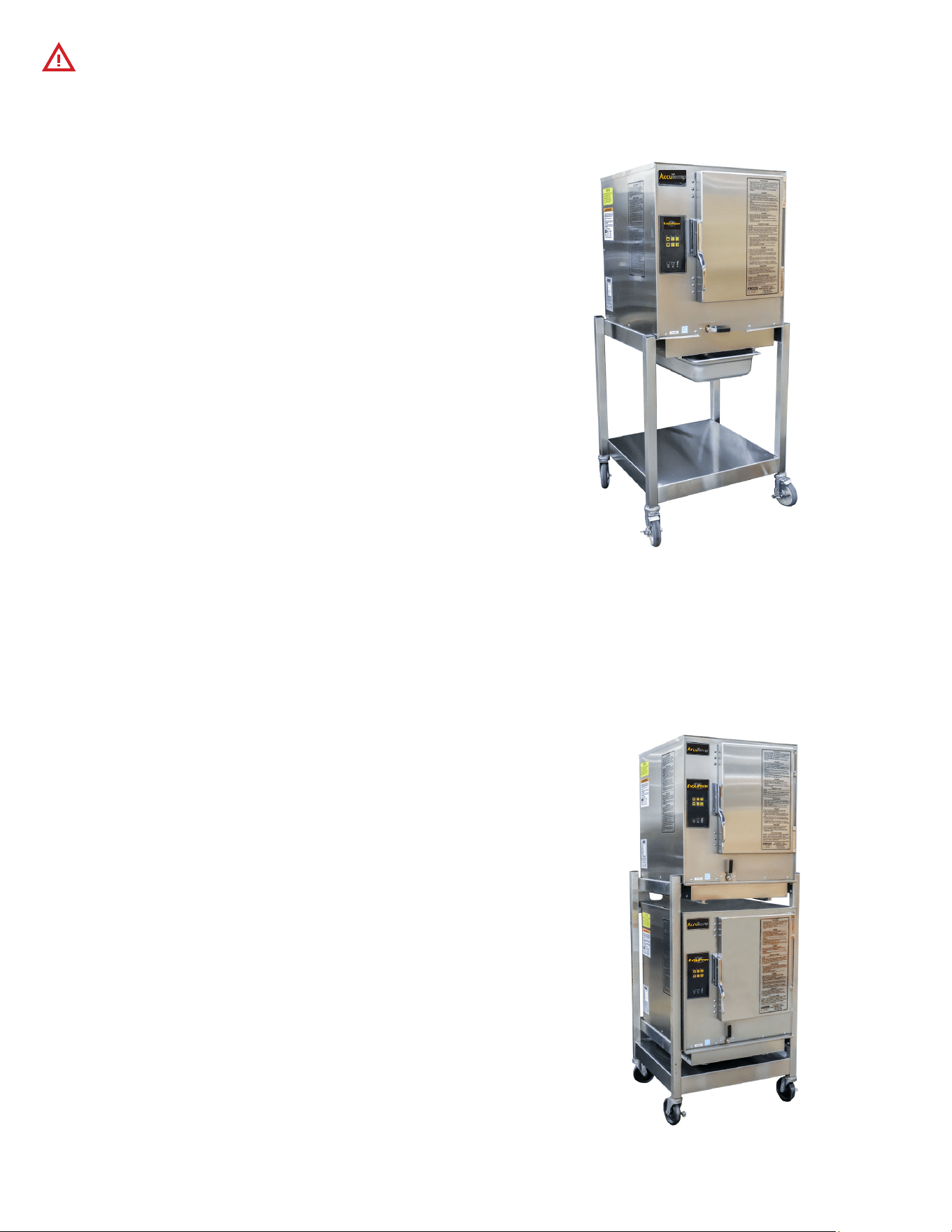
3.5.1 Single Steamer Stand Installation Instructions
The AccuTemp single stand can be equipped with adjustable
height feet or non-adjustable casters (FIGURE 3).
1. Before mounting a steamer on the stand with casters,
engage the two front locking casters, pressing on the “ON”
handle of the brake mechanism.
2. To mount the steamer, carefully lift and place it on the
horizontal mounting brackets ensuring that the (4) mounting
holes on the underside of the Evolution are lined up with
mounting holes of the brackets.
3. Then, using a 7/16” wrench, fasten one pair of the 1/4” -20
hex bolt and 1/4” split lock washer through the underside
of each stand bracket mounting hole into the Evolution and
tighten securely.
4. With the SNH-10 stand, level the steamer by adjusting the
feet found at the ends of each stand leg, either up or down
as needed.
FOR COMBUSTIBLE & NONCOMBUSTIBLE BUILDING MATERIALS
LOCATION
LEFT
3”
RIGHT
3”
REAR
3”
FOR OTHER SOURCES OF HEAT: FRYERS, OPEN RANGE, STEAM VENTS.
For open ame, this is the minimum distance from the ames while they
are in operation.
MP4010-2503
8
When installing units on a double stand, always install the
lower unit rst. Installing the upper unit rst could cause the
stand to topple.
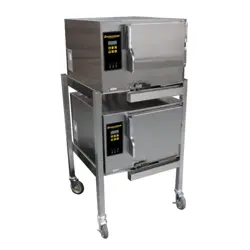
3.5.2 Double Stand Installation Instructions
The AccuTemp double stand can be equipped with adjustable
height feet or can be equipped with non-adjustable casters and
accommodates (2) N6 model Evolutions (FIGURE 4).
1. Before mounting a steamer on a stand with casters engage
the brakes on the two front locking casters, pressing on the
“ON” handle of the brake mechanism.
2. Always mount the rst EVOLUTION on the bottom of the
stand. To mount the bottom steamer, carefully lift and place
it on the horizontal mounting brackets, ensuring that the (4)
mounting holes on the underside of the Evolution are lined
up with the mounting holes on the brackets.
3. Then, using a 7/16” wrench, fasten one pair of the 1/4”-20
hex bolts and 1/4” split lock washers through the underside
of each stand bracket mounting hole into the Evolution and
tighten securely.
4. Once the bottom steamer has been installed, carefully
lift and place the top Evolution steamer on the horizontal
mounting brackets, ensuring that the (4) mounting holes
on the underside of the Evolution are lined up with the
mounting holes on the brackets.
5. Then, using a 7/16” wrench, fasten one pair of the 1/4”-20
hex bolts and 1/4” split lock washers through the underside
FIGURE 4: AUTOFILL UNITS ON A DOUBLE STAND
FIGURE 3: MANUAL FILL UNIT ON SINGLE STAND
MP4010-2503
9
3.6 Steamer Connections
The Evolution Gas Steamer is available in a connected and
connection-less models.
Both the connection-less and connected model will require a
gas connection and an electrical connection.
CONNECTED UNITS:
The connected model in addition to the gas and electrical
connection will require a water connection and access to a
oor drain or sink to route a drain hose (not supplied) to allow
condensate to be removed and to drain the steamer when
required.
See FIGURE 5 for identications of the required steamer
connections.
CONNECTIONLESS UNITS:
This model must be manually lled with tap water and must be
lled throughout the cooking process to assure consistent cook
times.
Do not use the “Low Water Indicator” as your indication
that this steamer requires water as this actually turns o the
heat to the product thus stopping the cooking process.
A full size steam table pan or a 1/1 gastronome pan must
installed in rails under the steamer any time the steamer is
operating and anytime that the steamer is being cleaned or
drained of the water in the cooking chamber. Failure to follow
this directions will cause a the steamer to fail which is not
covered under the limited warranty (FIGURE 6).
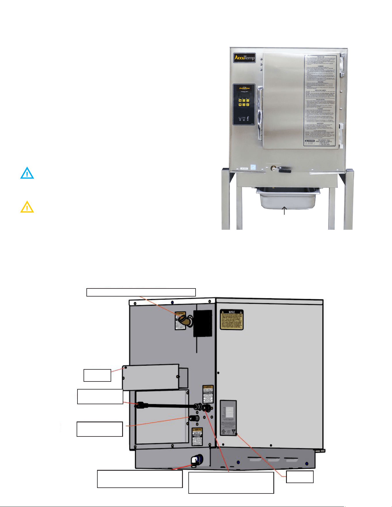
FIGURE 5 - TEXT ENCIRCLED BOLD ARE SHARED
CONNECTIONS BETWEEN BOTH MANUAL AND AUTO-FILL
UNITS
DRAIN PAN
FIGURE 6: MANUAL FILL UNIT ON SINGLE STAND
3/4” Cooking Chamber Exhaust Vent
Flue
Power Plug -
120VAC
3/4” Barbed Drain Connec-
tion (Connected Models Only)
3/4” GHT Potable Water
Connection (Connected Models
Only)
Data Tag
1/2 Gas Supply
Connection

MP4010-2503
10
3.7 Electrical Requirements and Notices
The electrical voltage requirement is listed on the data
plate that is located on the lower left side panel.
All AccuTemp Evolution Gas Steamers are supplied
with a power cord and plug that must be connected to a
standard a 15A (120V) or 20A (240V) grounded receptacle.
Make sure the voltage is within 10% of the voltage listed
on the steamer data plate.
Connection to any other voltage not identied on the
data plate will cause damage to the components and is not
covered under warranty.
Grounding provides a path for electric current to reduce risk of
shock.
This product is equipped with a power cord having a
grounding plug.
The plug must be plugged into a receptacle that is
properly installed and grounded in accordance with all National,
State and local electrical codes or in the absence of local
electrical codes with the National Electric Code, ANSI/NFPA 70,
or the Canadian Code, CSA C22.2 as applicable.
Under no circumstances shall the plugs grounding prong
be cut or bent to t a receptacle other than the one specied.
Do not use any adapters.
Any in-eld modication made that bypass the safety
features of this appliance will result in serious injury or death.
DO NOT DIRECT WIRE THIS APPLIANCE.
Any in-eld modications made without written
authorization from AccuTemp Products, Inc. will void all written
and oral warranties.
3.8 Gas Connections
3.8.1 Gas Requirements and Notices
The Evolution Gas Steamer is manufactured for the use of
gas indicated on the data plate. Contact AccuTemp Products
Technical Service Department if your gas supply does not
match the gas indicated on the steamer data plate.
MINIMUM recommended static pressure for gas is: NG
7inWC, LP 10inWC.
All gas connectors must be in accordance with the local
codes and must comply with the latest edition of the National
Fuel Federal Gas Codes, ANSI Z223.1.
A separate gas shuto valve (not supplied) should be
installed in the gas supply line.
Use a 3/4” or larger diameter dedicated commercial grade gas
supply line capable to handle a minimum of 60,000 BTU to
connect this steamer to the facility supply manifold to ensure a
sucient volume of gas.
The facility supply regulator and manifold must be sized
according to the gas load of all appliances connected to it. If
other gas appliances are connected to the supply manifold,
their gas load must be added to the calculations for properly
sizing the supply manifold and regulator.
Flexible residential appliance connection hoses are not
suitable for this appliance and will void any warranty.
If your steamer is located at an altitude of 2000 feet or
higher, the orice must be changed to allow appropriate gas
supply to the burners. Please contact the AccuTemp Products
Technical Services Department for assistance.
The steamer is supplied with an internal gas regulator that
is for the gas type and pressures on the steamer data plate. An
external regulator is not required unless the gas suply pressure
is more than 0.5psig. If an external regulator is required it must
be rated 125% of the steamer BTUH rate at the pressure higher
than the rated regulated pressure.
3.8.2 Gas Pressure Verication
The gas supply pressures for the internal regulator must
be veried with a calibrated manometer while the appliance is
operating in maximum load condition.
A 1/8” NPT tap is provided in the front of the internal regulator
to measure the burner STATIC pressure, see FIGURE 7.
Use a pipe joint compound or sealant designed for the use with
liqueed petroleum gas when replacing the 1/8” NPT tap.
Do not use an excessive amount of sealant in order to
prevent potential obstruction of the gas control valve.
3.8.3 Gas Pressure Adjustment Instructions
1. Ensure unit is connected to gas supply.
2. Turn gas o at supply.
3. Remove 1/8” NPT plug from dual solenoid control valve.
4. Use a 1/8” NPT tap to connect a manometer to the control
valve. Ensure manometer is set to read inches water
column.
5. Turn supply on and power unit on.
6. When unit powers on, the pilot valve will open and the
STATIC pressure will be present.
7. Once unit attempts ignition, the main valve will open and
the DYNAMIC pressure will register on the manometer.
8. The DYNAMIC pressure must be set to NG:3.5 inch WC. LP
10 inch WC.
9. To adjust the pressure, remove the dust cap on the
regulator as seen in Figure 7.
10. Adjustment screw can be turned using a slot head
screwdriver. Adjust while burner is on.
FIGURE 7
1/8” NPT
TAP
DUST CAP ON
REGULATOR
MP4010-2503
11
3.8.4 Flame Sense Rectication
The Evolution Gas Steamer utilizes a ame sensing circuit to
determine if the system has proper combustion. When the
system is turned on, gas is sent to the burner and an electronic
ignition tries to ignite the burner. The ignition module then
checks to see if ame is established in the burner.
If the ame sense feedback is within the proper range the
system will stay on until the pressure switch opens. The ignition
module continues to monitor the voltage and as long as its
within the proper range the burner will stay on. If the ame
sense reading falls below the threshold of 2.5uA (microamperes)
the steamer will go into lock out and will stop heating. There is
no exterior signal for a lockout.
1. The ame sense should be monitored and recorded as part
of the install.
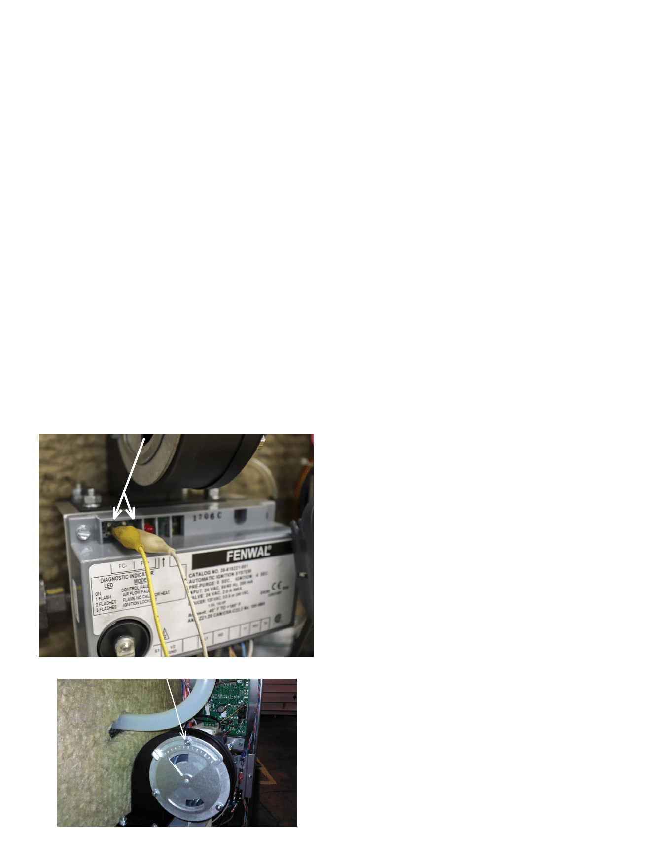
2. To test for ame sense, connect a multimeter to the FC+
and FC- pins on the ignition module (FIGURE 8). Set the
multimeter to test for microampere.
3. Run the unit and monitor the reading.
4. If the gas pressure is set correctly for the gas type the
reading should be 4 to 6 μA (Micro Ampere)
5. The air intake shutter is factory set to a value of 2.5 to 5.The
gap has been pre-set at the factory for best combustion
performance (FIGURE 9).
FIGURE 8
FC + & FC -
FIGURE 9
AIR SHUTTER
MP4010-2503
12
3.9 Connected Model - Additional Connections
3.9.1 Supply Water Line (FIGURE 10)
The installation of the water connection to the appliance is
the responsibility of the owner and or installer.
The installation of this appliance should comply with all
applicable federal, state or local plumbing codes.
The installation requires a check valve (or other approved
anti-back ow/ anti-siphon device) in all supply lines in accor-
dance with and as required by local, state and national health,
sanitation and plumbing codes. AccuTemp does NOT provide a
check valve included with the steamer.
• Design the water supply line so the unit can be moved for
service. Install a manual water valve between the water
supply line and the steamer supply line.
• A reinforced rubber or braided stainless steel appliance
hose rated for the temperature and pressure of the
water supply with a 3/4” garden hose type connection is
required.
• The Garden Hose Thread (GHT) connector used must
be suitable for potable water
• Do not apply pipe thread sealant to GHT
connections.
• Install a manual water shut-o valve (not provided)
between the cold water supply line and the appliance.
• Either hot or cold water can be connected to the
steamer. If hot is used, temperature must be less
than 180°F.
• The hose must not be sharply bent, kinked or twisted.
• If the steamer is close to a wall, use a right angle tting to
prevent kinking the hose
• Flush the water supply lines before connecting the lines to
the appliance.
• Connect the water supply lines to the steamer.
3.9.2 Drain Line Connection
Floor Drain
The steamer should be located close to, but not within
20” or directly over, a oor drain.
• Connect a ¾” ID reinforced rubber hose rated for 212°F
or higher to the drain tting on rear of the steamer with a
hose clamp.
• Run the hose to the drain. DO NOT directly plumb the
steamer to the drain, Leave a one-inch air gap between the
hose and the drain.
• The hose must drop 1/4” (inch) per foot to the drain.
• Ensure no loops form in the drain line as this can cause a
backup and will aect the operation of the unit
The unit should not be located within 20” of a oor drain.
Optional Drain Connection
Run the hose to a funnel tting leaving a one-inch gap between
the hose and the top of the funnel. The drain hose must slope
toward the oor drain or funnel.
FIGURE 10
WATER INLET
GAS CONNECTION
DRAIN CONNECTION
CONNECTED STEAMERS ONLY
STEAM EXHAUST VENT
DO NOT CONNECT TO GAS,
DRAIN OR WATER INLET
GAS EXHAUST FLUE
FIGURE 11
MP4010-2503
13
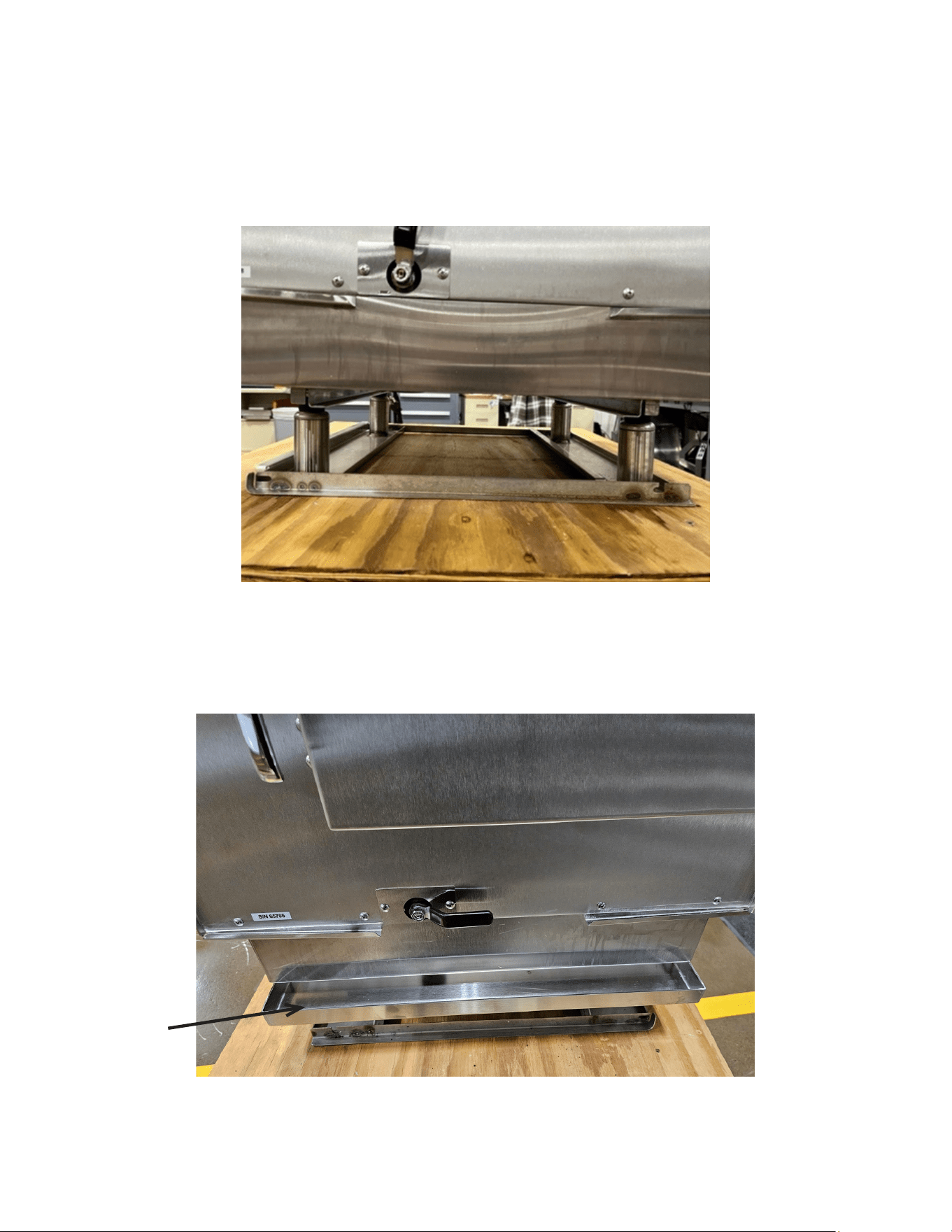
3.9.3 Condensate Rail Installation (Auto-Fill only)
• The condensate pan is placed inside the cooking chamber
during shipping, remove the rail from the chamber.
• Place under steamer making sure pan’s mounting plate is
tted into the drain pan rails (Figure 12 & 13).
FIGURE 12
FIGURE 13
Condensate Pan
MP4010-2503
14
3.10 Ventilation
The steamer produces water vapor along with the ex-
tremely hot products of combustion.
The ue should not be obstructed or blocked in any way.
Any in-eld modications made without written authorization
from AccuTemp Products, Inc. will void all written and oral war-
ranties.
DO NOT connect Drain or Vent lines on multiple appli-
ances. Each appliance should have its own dedicated drain and
vent.
The steam vent is provided with a 45 ° elbow. The steam
vent must not be obstructed. An obstruction will prevent cor-
rect operation of the steamer.
Applicable federal, state and/or local plumbing codes will
dictate when and if a hood is required.
When installing a gas red appliance in any location,
provisions should be made for adequate make up air.
Additionally the appliance should not be positioned in locations
where the appliance is subject to drafts.
Do not permit fans to blow at the appliance, and wherever
possible, avoid open windows near to the sides and back of the
appliance. Check wall fans to make sure air cross currents are
not created in the room.
3.10.1 Steam Vent Extension
When adding anything to the vent on the Evolution steamer,
care must be taken to prevent doing anything that puts a back
pressure on the steamer. Back pressure on the steamer may
interfere with the pressure switch that controls the heaters.
When the pressure switch senses pressure in the steamer is 0.5”
of water or more, it turns the heaters o. Therefore, anything
on the vent putting a pressure of just 0.5” water column on the
steamer turns the heaters o and prevents them from coming
on again until the pressure is relieved. Intermittent operation of
the steamer can often be traced to restrictions, low spots or a
plugged condensate drain in the vent tting assembly.
To prevent putting a back pressure on the steamer, vent piping
should have no restrictions and no low spots where water can
accumulate. Ventilation piping can be directed upwards toward
hoods or downward towards oor drains. Slightly dierent
approaches are required for each application.
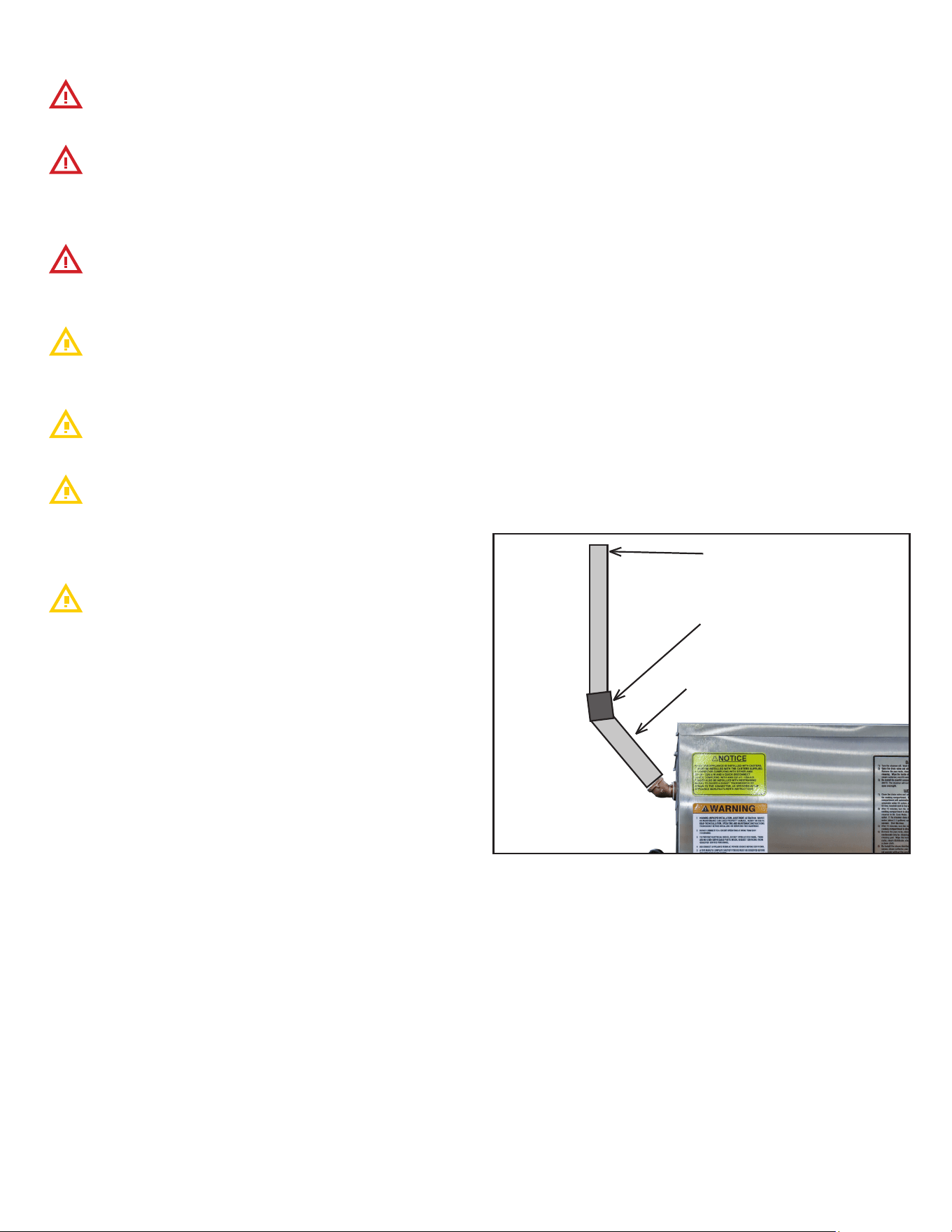
Extension Sloping Upward (FIGURE 14)
1. Use nominal ¾” copper, brass or stainless steel to prevent
ow restrictions. Larger inside diameter (ID) can be used
also
2. Pipe should slope upward a 1/4” per foot from the steamer
vent toward a vent hood to allow water condensing in it to
run back to the steamer and down the drain line. Minimum
recommended slope is ¼” per foot of hose length.
3. Use rigid pipe rather than exible tubing or hose to prevent
dips or sags in the pipe that may collect water. A puddle
of water in the piping just ½” deep will cause the steamer
to malfunction. Recommended pipe materials are rigid ¾”
copper tubing (7/8” OD) or brass/ 18-8 stainless steel pipe
(3/4 NPT or larger). Pipe hangers or pipe supports should
be used every six feet to prevent long runs from sagging.
4. A pipe union should be installed next to the steamer to
permit the vent to be easily disconnected. This allows the
steamer to be easily moved for servicing.
5. Total length of extended vent piping should not exceed 15
feet.
FIGURE 14
18” - 36” Long = 3/4” Diam-
eter brass pipe (both ends
threaded)
45 ° Elbow = 3/4” Diameter
brass pipe (both ends female)
6” - 10” Long - 3/4” Diameter
brass pipe (both ends threaded
male)
MP4010-2503
15
Mounting vent Extensions On Two Steamers on a Double
Stack Stand.
DO NOT connect Drain or Vent lines on multiple applianc-
es. Each appliance should have its own dedicated drain and vent.
Each steamer’s vent must be extended individually. Tying mul-
tiple vents together will result in the steamers being unable to
regulate heat.
For the both steamers, follow the instructions as provided above
in Extension Sloping Upward.
The lower steamer’s vent must exit above the top of the upper
steamer (FIGURE 16).
When designing the extension to slope downwards, whether us-
ing rigid or exible hosing, pipe hangers or pipe supports should
be used every six feet to prevent long runs from sagging. The
end of the hose/pipe should not be submerged to prevent steam
backups (FIGURE 17).
Extension Sloping Downwards (FIGURE 15)
1. Use nominal ¾” or larger inside diameter (ID) to prevent
ow restrictions.
2. Pipe should slope downwards from the steamer vent
to a oor drain to allow water condensing in it to run
unimpeded into the oor drain.
3. For downward sloping extension to a oor drain ONLY
– ¾ ID or larger reinforced silicone hose (auto radiator
hose) may be used. The hose end must be open and not
submerged. Avoid any low spots that will cause puddles of
water and increase of back pressure.
4. Total length of extended vent piping should not exceed 15
feet.
3/4” Diameter
brass pipe (both
ends threaded) or
reinforced silicone
hose.
Avoid low spots.
Total length should
not exceed 15 feet.
6” - 12” Long - 3/4” Diameter
brass pipe (both ends threaded
male)
Rotate factory
elbow to point
downwards
45 ° Elbow = 3/4”
Diameter
brass pipe (both ends
female)
FIGURE 15 - USING RIGID
PIPING
45 ° Elbow = 3/4” Diameter
brass pipe (both ends female)
18” - 36” Long = 3/4” Diam-
eter brass pipe (both ends
threaded)
6” - 10” Long - 3/4” Diameter
brass pipe (both ends threaded
male)
FIGURE 16
FIGURE 17
Two ¾ ID or larger reinforced
silicone hose (auto radiator
hose) may be used, allowing
a 1/4 Total Length MUST NOT
exceed 15 feet. Hoses must
not be joined in any way
No loops in hose - preventing
condensation
Ends of hose must be open
to air and not submerged
MP4010-2503
16
4. OPERATION
RISKS RESULTING FROM CONTACT WITH VERY HOT
OBJECT:
STEAM
When opening the door, particularly during steamer
operation, always stand in such a way that the hot steam
escaping from the partially open door cannot scald you.
Open the door only partially and open fully only once the
steam has escaped.
HOT
Hot areas may form during the cooking process, especially
on the cookware, grills and the inner side of the door. Use
protective gloves whenever handling hot objects.
During the cooking process, do not handle cookware
containing liquids or liquid foodstus located above eye level.
Danger of burns.
Be sure all operators read, understand and follow
the information contained in this manual including caution
warnings, operating instructions and safety instructions.
When accessing the cooking chamber, be sure to always
stand back while slowing opening the door to allow the
chamber to vent o the steam. Never reach into the cooking
chamber before it has completely vent o the steam.
Never use wet or damp gloves as moisture can conduct
heat quickly.
Keep the oor in front of the equipment clean and dry. If
spills occur, clean immediately to avoid potential injuries.
Do not manually ll water above the water level mark on
the left side of the cooking chamber.
Do not use abrasive (or steel) materials, such as wire
brushes, metal scouring pads to clean the cooking chamber
bottom.
4.1 Operation Introduction
The AccuTemp Evolution gas steamer uses the time proven
method of cooking with steam. Once the cooking time expires,
the steamer can be set to the “Hold Mode”. In this mode, the
controller regulates the internal temperature. At this time,
steam is no longer generated and the cooking chamber is held
at the preset temperature at a relative humidity of 100%. This
eliminates food from drying out by suppressing the evaporation
of the products natural moisture. As a result, most food
products can be held in a ready-to-serve state for several hours
after cooking, with no appreciable loss in taste, appearance or
consistency.
4.2 Sequence of Operation
• When power button is depressed digital display will power
on and display “PrE.”
• On connected models, low water light will illuminate and
unit will begin to ll. On connectionless models, low water
light will illuminate and alarm will sound until water is
added to the cooking chamber up to the water ll level.
• When the unit has nished lling, low water light will
extinguish and alarm will stop. Unit will then begin ignition
cycle. Unit will begin to heat, do not open door as this will
slow preheat process.
• Pressing the temperature button will allow users to see
current temperature.
• Unit will display “Coo” on display when cooking
temperature (approx 212F) has been achieved. The unit
will maintain this temperature until powered o or user
switches to Hold mode. Product can now be added.
OPERATOR DISPLAY &
KEYPAD
DRAIN PAN - CUSTOMER SUPPLIED
MAGNETIC
DOOR LATCH
DRAIN VALVE
FIGURE 18

MP4010-2503
17
OPERATOR
DISPLAY
COOK or HOLD
DISPLAY
TEMPERATURE
OVER-
TEMPERATURE
LAMP
HIGH WATER LAMP
LOW WATER LAMP
SET TIMER
INCREASE
VARIABLE
DECREASE
VARIABLE
ON/OFF
FIGURE 19

MP4010-2503
18
4.3 Control Program Mode
To enter Program Mode for the controller function parameters, turn the unit OFF then depress and hold the
DOWN arrow and DSPLY TEMP keys for a minimum of 5 seconds. The control is now in Program Mode and
LED1,2 and 3 will blink, and the keypad will be recongured as shown in the following table:
Program # Program Title Minimum Value Maximum Value Default Value
P01 Hold Temp Minimum Temp Maximum Temp 180F/82C
P02
Default Timer Value 1 -
Hours
0 8 0
P03
Default Timer Value 1 -
Minutes
0 59 30
P04 Timer Function 0=Independent 1=Dependent 0=Independant
P05
Default Timer Value 2 -
Hours
0 8 0
P06
Default Timer Value 2 -
Minutes
0 59 20
P07
Default Hold Timer Value -
Hours
0 8 2
P08
Default Hold Timer Value -
Minutes
0 59 0
P15 Hold Key Disable 0=NO 1=YES 0=NO
P16 Degrees F or Degrees C 0=F 1=C 0=F
P17 RESET TO DEFAULT 0=NO 1=YES 0=NO
Users should only adjust settings in the programs listed in the above table. All other programs
should be left at factory defaults.
To navigate through the program menu, Depress the UP arrow to cycle between the Program Level
and the Value Level. Depress the COOK/HOLD key or the DSPLY TEMP key to cycle through the
Level selected.
Example - Change Hold Temperature
• Turn the unit OFF then depress and hold the DOWN arrow and DSPLY TEMP keys for a minimum of 5
seconds. The control is now in Program Mode and LED 1, 2 and 3 will blink.
• P01 will show on the display. Depress the UP arrow to shift from Program level to Value level. The display
will change to show 180F. Depress the COOK/HOLD key to increase the hold temp. Depress the DSPLY
TEMP key to decrease the hold temp. Once the desired hold temp has been reached, depress the TIMER
key to save the new programming. The unit will power down. Power back on to resume operation.
Example - Change Default Timer Value 1 - Minutes
• Turn the unit OFF then depress and hold the DOWN arrow and DSPLY TEMP keys for a minimum of 5
seconds. The control is now in Program Mode and LED 1, 2 and 3 will blink.
• P01 will show on the display. Depress the COOK/HOLD key to cycle through the Program level until the
display shows P03. Depress the UP arrow to shift from Program level to Value level. Depress the COOK/
HOLD key to increase the minutes on the timer. Depress the DSPLY TEMP key to decrease the minutes
on the timer. Once the desired time has been set, depress the TIMER key to save the new programming.
The unit will power down. Power back on to resume operation.
MP4010-2503
19
4.3 Partial Loads
The Evolution is designed to cook quickly with exceptional
pan-to-pan uniformity on full loads of food. Excellent pan-to-
pan uniformity can be achieved with partial loads if the pans are
optimally placed in the steamer.
For partial loads using 2½” deep pans, the top position in the
steamer is used rst followed by the second pan placed in
third pan position from the top and then the third pan in the
fth pan position from the top (FIGURE 20). Placing the pans in
these positions will optimize the cooking time and pan-to-pan
uniformity.
FIRST PAN
THIRD PAN
SECOND PAN
FIGURE 20
4.4 Daily Preparation for Use - Connected
Preparing the Evolution Connected model for use each day
requires very little time and eort. Simply verify that the steamer
is clean, the water line to the steamer is turned on and the drain
valve is in the closed position. Close the door and push the ON/
OFF key on the keypad. The steamer will automatically ll and
preheat.
Since the Evolution automatically senses the water level and
rells as required. There is no need to manually ll the steamer.
PREHEATING
1. Depress the On/O Key to turn on the steamer. The display
will indicate PrE while in Cook Mode and the temperature
while in the Hold Mode.
2. Once the steamer is preheated and ready to cook, the
display will indicate the COO (Cook Mode) or HLd (Hold
Mode).
3. Depress the DISP TEMP button to display the current
cooking temperature.
COOKING
1. Depress the COOK/HOLD button to select the Cook Mode
(COO).
2. Open the door and place food into the cooking chamber.
Shut the door. Cooking begins immediately.
3. Timer — Depress the TIMER button and depress the
ARROW keys until the desired time is displayed. The timer
starts automatically. At the end of the timed cycle, a beeper
will sound.
4. Depress the DISP TEMP button to display the current
cooking chamber temperature.
HOLDING
In “Hold” the steamer temperature is set for 180° F from the
factory. The hold temperature can be changed to a single value
for temperatures ranging from
150°F to 190°F if required. Contact the AccuTemp Technical
Service Department for assistance at 800.480.0415. Hold can
also be used during downtimes to save energy and water while
keeping the steamer preheated.
1. Depress the COOK/HOLD button to select the Hold Mode
(HLd).
2. Open the door and place food into the cooking chamber.
Shut the door.
3. Food will be held at the preset holding temperature. The
factory setting is set at 180° F.
4. Depress the DISP TEMP button to display the current
cooking chamber temperature.

MP4010-2503
20
4.5 Daily Preparation for Use - Connectionless Model
Preparing the Evolution Connection-Less model for use each
day requires very little time and eort. Simply verify that the
steamer is clean, the drain valve is in the closed position and the
cooking chamber is lled with approximately 2½ Gallons of tap
water. Close the door and push the ON/OFF key on the keypad.
The water level will need to be monitored and lled as required.
Do not use the low water warning lamp as the indicator to
check the water level as this can damage the steamer over time.
PREHEATING
1. Depress the ON/OFF Key to turn on the steamer. The
display will indicate PrE.
2. Once the steamer is preheated and ready to cook, the
display will indicate COO (Cook Mode) or HLd (Hold Mode).
3. Depress the DISP TEMP button to display the current
cooking chamber temperature. MAX temperature at sea
level in 212°F
COOKING
1. Depress the COOK/HOLD button to select the Cook Mode
(COO).
2. Open the door and place food into the cooking chamber.
Shut the door.
Cooking begins immediately.
3. Timer — Depress the TIMER button and depress the
ARROW keys until the desired time is displayed. The
timer starts automatically. At the end of the timed cycle, a
beeper will sound.
4. Depress the DISP TEMP button to display the current
cooking chamber temperature.
HOLDING
In “Hold” the steamer temperature is set for 180°F
from the factory. The hold temperature can be changed to a
single value for temperatures ranging from 150° F to 190° F if
required. Contact the AccuTemp Technical Service Department
for assistance at 800.480.0415. Hold can also be used during
downtimes to save energy and water while keeping the steamer
preheated.
1. Depress the COOK/HOLD button to select the Hold Mode
(HLd).
2. Open the door and place food into the cooking chamber.
Shut the door.
3. Food will be held at the preset holding temperature. The
factory default setting is set at 180° F.
4. Depress the DISP TEMP button to display the current
cooking chamber temperature.
4.6 Cleaning
Do not use a water jet or pressure washer to clean the
steamer.
After cleaning procedure is complete, steamer door must
be left open to allow steamer to dry. Not doing so will decrese
life of door gasket.
If local water conditions cause rust inside the steamer or
heavy mineral buildup, request the AccuTemp Additional Clean-
ing Recommendations.
4.6.1 Daily Cleaning
1. Turn the steamer o. Wait for the steamer to cool.
2. Open the drain valve and allow the cooking compartment
to drain completely. Remove the pan racks, steam collector,
overll sensor and condensate tray for cleaning. Wipe the
inside of the cooking chamber, pan rails, steam collector,
overll sensor, and condensate tray with a clean cloth
(FIGURE 19 & 20).
3. Re-install the overll sensor, steam collector, pan rails and
condensate tray. Leave the door open overnight.
(NOTE: The steamer will not operate without the overll
sensor. An alarm will also sound.) Only on steamers with
water connections.
4.6.2 Weekly Cleaning
1. Close the drain valve and add 1 cup (8 ounces or 0.24 liters)
of white vinegar to the cooking compartment. Start the
steamer in the Cook Mode. The cooking compartment will
automatically ll with water. If the steamer does not have
the automatic water ll option, manually add water (2.5
gallons) up to the water ll line, located next to the water
sensors. Shut the door.
2. After 15 minutes, turn the steamer o. Open the drain valve
and allow the cooking compartment to drain completely.
Close the drain valve. Start the steamer in Cook Mode. The
cooking compartment will automatically ll with water. If
the steamer does not have the automatic water ll option,
manually add water (2.5 gallons) up to the water ll line,
located next to the water sensors. Shut the door.
3. After 15 minutes, turn the steamer o. Open the drain valve
and allow the cooking compartment to drain completely.
Wait for the steamer to cool.
4. Remove the pan racks, steam distributor, steam collector,
overll sensor and condensate tray for cleaning. Clean the
water sensors with a non-metallic cleaning pad. Wipe the
inside of the cooking compartment, water sensors, pan
racks, steam distributor, steam collector, overll sensor, and
condensate tray with a clean cloth.
5. Re-install the steam distributor (do not use tools to tighten
the knobs), overll sensor, steam collector, pan racks and
condensate tray.
(NOTE: The steamer will not operate without the overll
sensor. An alarm will also sound.) Only on steamers with
water connections.
MP4010-2503
21
OVER FILL SENSOR FLOAT
LEFT WALL OF COOKING
CHAMBER
LOW WATER
SENSOR
UPPER LEVEL
WATER SENSOR
DRAIN
STEAM
DISTRIBUTOR
STEAM
COLLECTOR
PAN RACKS
PAN RACKS
FIGURE 21
4.6.3 How to to Protect Stainless Steel
AccuTemp Steamers are made from high quality stainless steel. To protect the equipment, we would recommend the following steps:
1. Use the proper tools. Never use sandpaper on stainless steel, as it can cause scratches in the steel, allowing corrosion to form.
Use non-abrasive tools, like soft cloths and plastic scouring pad, stainless steel pads (scrub in direction of polishing marks).
2. Clean with the polish lines or “grain” Scrub in a motion parallel to the lines when visible lines are present. Use a soft cloth or
plastic scouring pad when grain cannot be seen.
3. Use alkaline, alkaline chlorinated or non-chloride containing cleaners. Ask your supplier for an alternative if your present cleaner
contains chlorides. Avoid cleaners containing quaternary salts to avoid pitting and rusting.
4. Keep your food equipment clean. Following the cleaning instructions in Section 4.6 will greatly reduce the chances of corrosion
and rust.
5. Rinse and wipe equipment and supplies if chlorinated cleaners are used, dry immediately. Wipe o standing water as soon as
possible, especially when it contains cleaning agents.
6. Never use hydrochloric acid (muriatic acid) on stainless steel.
7. Regularly re-passivate with oxalic acid (Bar Keepers Friend or equivalent) or citric acid (Citri-surf / Citri-clean or equivalent) .
Note – these materials are stronger and more eective than vinegar. These water based acids remove traces of steel and acti-
vate the chromium oxide passive layer.
8. Always rinse the unit with clean water and dry with the steamer door and drain valve open.

MP4010-2503
22
5. Troubleshooting
If these don’t solve your problem contact our Technical Service Department.
• Phone - 800.480.0415 or 260.469.3040
• Email - service@accutemp.net
• Web site - www.accutemp.net
5.1 Steamer Will Not Power On
• Verify that the steamer is plugged into the proper outlet.
• Verify the the external breaker is on.
• If the ‘High Water’ warning light is on open the drain valve to drain the water until the light goes
out.
• Verify that the oat ball is in place.
5.2 Steamer Will Not Fill with Water
• Ensure water supply to unit is turned on.
• Clean two water sensors in cooking cabinet
5.3 Steamer is Overlling with Water (Connected)
• Ensure unit is level.
• Clean two water sensors in cooking cabinet.
5.4 Steamer Does Not Heat
• If the operators display doesn’t light up, see Section 5.1.
• Verify the steamer door is closed, as the unit will not heat when the door is open.
• Open and the shut the door to restart the ignition system.
5.5 Steam Comes Out of Door (Overpressure)
• Verify that the door is completely closed and latched.
• Wait a minute to see if it stops. After the steamer rells with water it is normal for some steam to
come out the door for a brief amount of time, usually less that one minute.
5.6 Steamer Temperature is Low
• When the steamer automatically rells the fresh water, the temperature of the steamer will drop.
The steamer should reheat quickly.
• If -99F or -1F appears call AccuTemp for assistance.
• If frozen product is added the temperature will take time to recover.
• Opening and closing the door frequently can lower the temeperature and increase cook times.

MP4010-2503
23
INFORMATION
IMPORTANT SERVICE INFORMATION
AccuTemp Product, Inc. Technical & Customer Support Technician
Mon-Fri: 7AM- 7PM EST
Saturday: 9AM – 5PM EST
Sunday: On Call – Leave a voice mail and a tech will call you back
800.480.0415 or 260.469.3040
SERVICE
INFORMATION
GENERAL SERVICE INFORMATION
All service request during the warranty period of this appliance must be
directed to the AccuTemp Products, Inc. Technical Service Department or
the service call may not be covered by the limited warranty.
WARNING
Only an AccuTemp Products Inc. Authorized Service Personnel or Representative
must perform service. Service performed by unauthorized personnel will void all
warranties.
INFORMATION
Conventional Steamers require scheduled maintenance (such as boiler maintenance)
at frequent intervals) The Evolution design doesn’t require this type of scheduled
maintenance. It is recommended that you schedule a yearly review of the Evolution
with a AccuTemp Authorized Service Representative to keep your steamer in optimal
operation
MP4010-2503
24
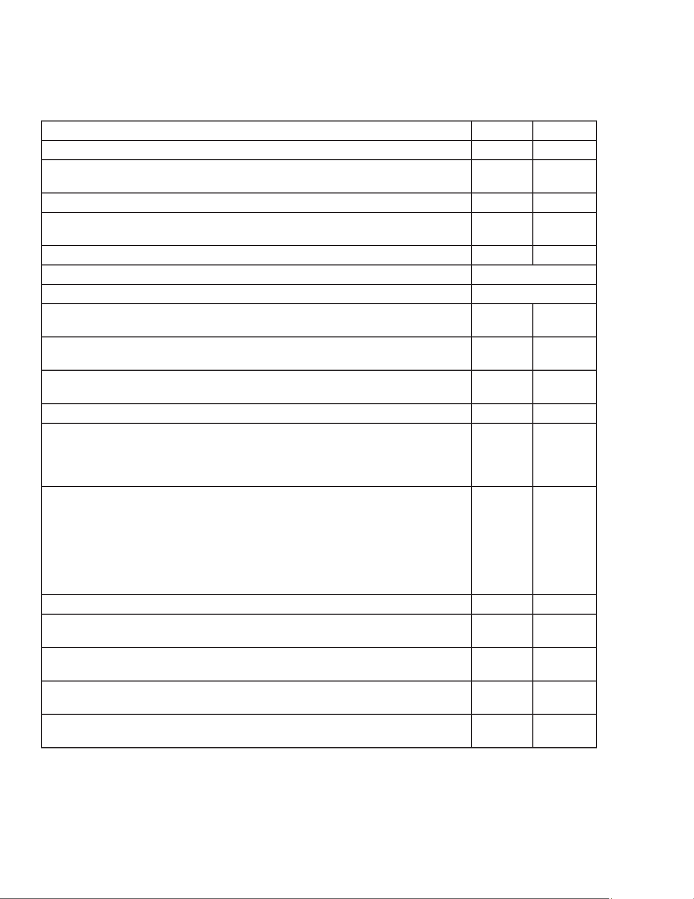
PM TASK DECRIPTION DAILY ANNUAL
Verify that the Steamer is level.
X
Verify the operation of the control panel. When a button is pressed the
display should register the input and a beep should sound.
X
Verify the operation of the indicator lamps.
X
Clean water ll sensors with non abrasive metallic pad. DO NOT use
sandpaper.
X
(AUTO-FILL ONLY) Ensure unit lls with water to the water level line.
X
Lubricate hinges and door latch with a food grade silicon spray
Monthly
Lubricate stand casters
Monthly
Inspect AC power cord for degradation or bare wires. Replace if defective
or suspect
X
Inspect door gasket for cuts and degradation. Replace if damaged. We
suggest replacing once a year.
X
Inspect Steam distribution panel gasket for cuts and degradation. Replace
if damaged. We suggest replacing once a year
X
Inspect and clean steam vent, condensate line ttings and hoses.
X
Inspect the ue for foreign particulate that has fallen inside. Remove any
particulate. Check that the ue has not been pushed in. If the ue has
been pushed in, pull the ue out so that ue opening is at the original
shape.
X
Verify the operation and condition of the igniter probe/ame sense
assembly. Probes should be cleaned with a stainless steel wire brush and/
or emery cloth. A stainless steel knife can also be used or a dollar bill.
Caution: DO NOT use any abrasive that contains
Silica. This will leave a coating on the ame sensor that could cause the
unit not to light. Install Electrode Ignitor Assembly if cleaning doesn’t
work. We recommend replacing every two years.
X
Clean Gas Orice
X
Inspect the control compartment for foreign particulate and any loose
wiring or connections.
X
Verify that the dynamic operating pressure of the unit is at NG: 3.5”WC/
LP: 10”WC
X
Check Pressure Switch for correct operation. Recommend to replace
every two years.
X
Inspect external and internal water connections and condensate lines for
degradation and leaks. Replace as necessary
X
PREVENTATIVE MAINTENANCE
Note: Accutemp approved service providers should complete any tasks involving access to gas
and electrical systems.

MP4010-2503
25
LIMITED WARRANTY
One Year– Parts and Labor
U.S. & Canada Only
AccuTemp Products, Inc. (AccuTemp) warrants that your AccuTemp equipment will be free of
defects in material and workmanship under normal use for a period of twelve (12) months
from installation or fteen (15) months from date of shipment from AccuTemp, whichever date
rst occurs (the Warranty Period). Registration of AccuTemp equipment is required at the
time of installation. Damage to AccuTemp equipment that occurs during shipment must be
reported to the carrier, and is not covered under this warranty. The reporting of any damage
during shipment is the sole responsibility of the commercial purchaser/user of such AccuTemp
equipment.
AccuTemp provides an active service department, which should be contacted and advised
of service issues, regardless of the warranty period. During the warranty period, AccuTemp
must be contacted for warranty repairs and agrees to repair or replace, at its option,
F.O.B. factory, any part which proves to be defective due to defects in material or
workmanship, provided the equipment has not been altered in any way and has been properly
installed, maintained, and operated in accordance with the instructions in the AccuTemp
Owners Manual. During the warranty period, AccuTemp also agrees to pay for any factory
authorized equipment service agency (within the continental United States and Canada) for
reasonable labor required to repair or replace, at our option, F.O.B. factory, any part which
proves to be defective due to defects in materials or workmanship, provided the service
agency has received advance approval from AccuTemp factory service to perform the repair or
replacement. This warranty includes travel time not to exceed two hours and mileage not to
exceed 50 miles (100 miles round trip), but does not include post start-up assistance or training,
tightening of loose ttings or external electrical connections, minor adjustments, maintenance,
or cleaning. AccuTemp will not reimburse the expense of labor required to replace parts after
the expiration of the warranty period.
Proper installation is the responsibility of the dealer, owner-user, or installing contractor and
is not covered by this warranty. Improper installation can aect your warranty. Installation
is the responsibility of the Dealer, Owner/User or the Installation Contractor. See the
Installation section of the Owners Manual. While AccuTemp products are built to comply
with applicable standards for manufacturers, including Underwriters Laboratories (UL) and
National Sanitation Foundation (NSF), it is the responsibility of the owner and the installer to
comply with any applicable local codes that may exist.
AccuTemp makes no other warranties or guarantees, whether expressed or implied, including
any warranties of performance, merchantability, or tness for any particular purpose.
AccuTemp liability on any claim of any kind, including negligence, with respect to the
goods and services covered hereunder, shall in no case exceed the price of the goods
and services, or parts thereof, which gives rise to the claim. In no event shall AccuTemp
be liable for special, incidental, or consequential damages, or damages in the nature of
penalties.
This constitutes the entire warranty, which supersedes and excludes all other
warranties, whether written, oral, or implied.

MP4010-2503
26

MP4010-2503
27
INFORMATION
IMPORTANT SERVICE INFORMATION
AccuTemp Product, Inc. Technical & Customer Support Technician
Mon-Fri: 7AM- 7PM EST
Saturday: 9AM – 5PM EST
Sunday: On Call – Leave a voice mail and a tech will call you back
• Phone - 800.480.0415 or 260.469.3040
• Email - service@accutemp.net
• Web site - www.accutemp.net
AccuTemp product may be covered by
one or more US Patents.
See www.accutempip.net