ACCUTEMP PRODUCTS INC
8415 N. CLINTON PARK DR ● FORT WAYNE, IN 46825 ● 800 480-0415 ● www.accutemp.net
SP8026-1201 Email: [email protected]
EVOLUTION
NATURAL GAS / PROPANE
SERVICE MANUAL
In the event a GAS ODOR is DETECTED, SHUTDOWN all appliances at the Main Gas Shut-Off
Valve and contact the local Gas Company or Gas Supplier Service.
WARNING
DO NOT store or use Gasoline, or any other Flammable Vapor and/or Liquids in the vicinity of this
or any other appliance.
WARNING
In the event of a Power Failure, DO NOT attempt to operate this appliance.
WARNING
IMPROPER installation, adjustment, alteration, service, or maintenance can cause personal injury
or death; and/or property damage. Read the installation, operation, and service/maintenance
instructions thoroughly; before installing or servicing this equipment.
WARNING
Only QUALIFIED service technicians/electricians should perform the equipment installation, to
ensure that all electrical and safety requirements are met; and that all wiring is performed in
accordance with all national, state, and local electrical codes.
WARNING
IMPORTANT FOR YOUR SAFETY
SP8026-1201 i
The Safety Instructions listed on this page below, should be posted
in a prominent location as a reminder of safe practices; as well as,
recommended actions to follow in the event of an equipment
or facility’s utility issue.
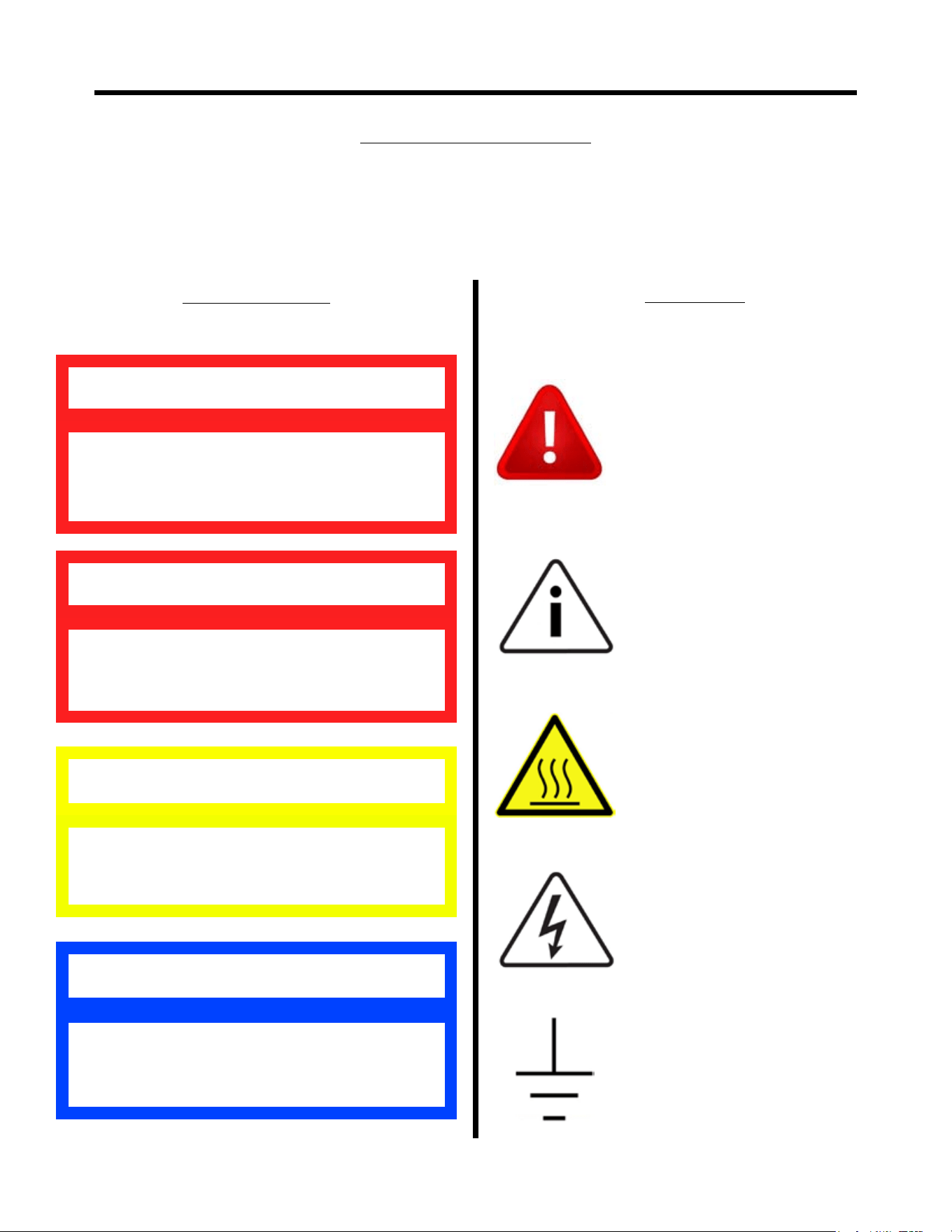
WARNING SYMBOL DEFINITIONS
SYMBOL DEFINITIONS
Symbols are used to attract your attention to possible dangers. They are only effective if
the operator uses proper accident prevention measures. Some of the symbols are boxed
text; while others maybe just picture icons. Please give this information the respect they
deserve for safe operation.
Indicates a potentially hazardous situation;
which, if unchanged, will result in death or
serious injury.
WARNING
Indicates an imminently hazardous situation;
which, if unchanged, will result in death or
serious injury.
DANGER
Indicates a potentially hazardous situation;
which, if unchanged, will result in minor or
moderate injury.
CAUTION
Advises the reader of information or
instructions, vital to the operation or
maintenance of the equipment.
NOTE
Warning Text Boxes
Below are denitions of the warning text boxes.
Symbol Icons
Below are denitions of the symbol icons used
in this manual.
ALERT
Noties the reader of an important
message or warning; usually a
safety related message.
INFORMATION
Noties the reader of an important
information that may or may not
be safety related.
CAUTION -
HOT SURFACE
DANGEROUS
VOLTAGE
EARTH GROUND
SP8026-1201 ii

ELECTRICAL SHOCK HAZARD WHILE WORKING ON
ENERGIZED EQUIPMENT.
Unplug equipment prior to removing any components effected by electricity.
FLAMMABLE GAS HAZARD WHILE WORKING ON GAS
EQUIPMENT.
Shut-Off the Supply Gas Valve to the equipment prior to removing any
components effected by supplied gas.
BURN HAZARD WHILE WORKING ON STEAM PRODUCING
EQUIPMENT.
When accessing the cooking chamber, be sure to always stand back while slowing
opening the door to allow the chamber to vent off the steam. Never reach into the cooking
chamber before it has completely vented off the steam.
Never reach into the cooking chamber or handle hot items without wearing the proper
heat protective gloves. Steam coming out of the holes on the right side of the cooking chamber
is invisible and can cause severe burns.
Water inside the steam chamber, creating steam, has a temperature of 212°F and will
cause burns if touched or spilled on the skin.
PERSONNEL INJURY HAZARD WHILE PICKING UP OR
MOVING HEAVY EQUIPMENT.
Always use 2 people and proper lifting techniques when picking-up, moving, or
ipping-over heavy equipment.
SLIP & FALL HAZARD WHILE WORKING ON WATER
HOLDING EQUIPMENT.
Keep the oor in front of the equipment clean and dry. If spills occur, clean them up
immediately to avoid potential injuries.
DANGER
SAFETY PRECAUTIONS
SP8026-1201 iii

WARNING & CAUTION NOTES
DO NOT• use abrasive materials, such as wire brushes or metal scouring pads to
clean the Water Sensors.
DO NOT• use Aluminum Oxide Sandpaper to clean the Water Sensors or Ignitor/
Flame Sense Probes. It leaves a residue that will not allow Water Sensors to work
properly.
DO NOT• manually ll water above the Water Level Mark on the left side of steam
chamber above the High Limit Level Sensor.
CAUTION
ONLY QUALIFIED SERVICE TECHNICIANS
SHOULD PERFORM MAINTENANCE ON
THIS EQUIPMENT.
WARNING
SP8026-1201 iv

SAFETY
Important For Your Safety.......................................................................................................................................i
Warning Symbol Denitions..................................................................................................................................ii
Safety Precautions................................................................................................................................................iii
Warning & Caution Notes.....................................................................................................................................iv
T.O.C. & MANUAL HISTORY
Table of Contents...............................................................................................................................................v-vi
Revision Sheet........................................................................................................................................................1
NOTES
Operational Condition Notes.................................................................................................................................2
Troubleshooting Notes...........................................................................................................................................3
OPERATIONAL & COMPONENT INFORMATION
Purpose Reference of Main Component Chart...................................................................................................4-6
Additional Component Part Numbers....................................................................................................................6
Sequence of Operation........................................................................................................................................7-9
Modifying Control/Keypad Program Settings.....................................................................................................10
TROUBLESHOOTING
Troubleshooting Flow-Diagram...........................................................................................................................11
Flow-Diagram Reference Troubleshooting Chart..........................................................................................12-14
COMPONENT REMOVAL & INSTALLATION
Location of Electrical Components Picture Overview.........................................................................................15
Electrical Components Removal & Installation.............................................................................................16-20
Cord & Plug Assembly...............................................................................................................
Water Sensor Control Board.......................................................................................................
Water Sensors..............................................................................................................................
Transformer.................................................................................................................................
Temperature (RTD) Probe...........................................................................................................
Control/Keypad Board................................................................................................................
Overtemp Switch (ThermalLimit SW3)......................................................................................
Ignition Module...........................................................................................................................
Time-Delay Relays......................................................................................................................
Chamber Pressure Switch............................................................................................................
Control Relays.............................................................................................................................
Ignitor & Flame Sense Probe......................................................................................................
Door Switch................................................................................................................................
Fuses...........................................................................................................................................
TABLE OF CONTENTS
16
16
16
17
17
17
18
18
18
19
19
19
20
20
SP8026-1201 v

TABLE OF CONTENTS
COMPONENT REMOVAL & INSTALLATION (CON’T)
Location of Gas Components Picture Overview..................................................................................................21
Gas Components Removal & Installation......................................................................................................22-24
Power Burner Blower...................................................................................................................
Gas Control Valve.........................................................................................................................
Gas Enrichment Valve..................................................................................................................
Power Burner Blower Pressure Switch........................................................................................
Gas Orice...................................................................................................................................
Location of Gas Burner & Gas Burner Box Picture Overview............................................................................25
Gas Power Burner Removal & Installation......................................[2 PERSONS REQUIRED].......................26
Gas Power Burner Box Removal & Installation..............................[2 PERSONS REQUIRED]..................27-28
Heat Transfer Plate Location Picture Overview...................................................................................................29
Heat Transfer Plate Removal & Installation.....................................[2 PERSONS REQUIRED].................30-31
Heat Transfer Plate Installation Notes & Cautions..............................................................................................32
Miscellaneous Components Removal & Installation.....................................................................................33-34
Auto-Fill Valve............................................................................................................................
Overll (Reed) Switch..........................................................[2 PERSONS REQUIRED]..........
Float Ball (Magnetic)...................................................................................................................
Drain Ball-Valve...................................................................[2 PERSONS REQUIRED]...........
Drip Pan.......................................................................................................................................
Door Components Removal & Installation....................................................................................................35-37
Door Assembly..............................................................................................................................
Inner Door Panel...........................................................................................................................
Door Handle Latch Assembly......................................................................................................
Door Hinge...................................................................................................................................
Door Gasket..................................................................................................................................
SCHEMATIC & CHARTS
Electrical Schematic AT1T-3736 Rev G (S/N 36980 and Below).......................................................................38
Electrical Schematic AT1T-3736 Rev H (S/N 36981 and Above).......................................................................39
Gas Orice Size to Altitude Chart.......................................................................................................................40
Ignitor/Flame Sense Probe Spacing Measurements.............................................................................................41
33
33
34
34
34
35
35
36
36
37
22
22
23
23
24
SP8026-1201 vi

REVISION SHEET
SP8026-1201 Pg 1
Current Revision: 1201 Prior Revision: N/A
Date: 1/31/12 Date: N/A
Change:
Initial Release.
OPERATIONAL CONDITION NOTES
The Water Column (WC) value for the gas pressure being supplied to the steamer •
should be between: Natural Gas = 7” to 10” WC Propane Gas = 11” to 13” WC.
If the supplied gas pressure coming into the steamer is .5 PSI (13.8” WC) or •
higher; an External Gas Regulator is needed in-line, prior to entering the steamer.
If an External Regulator is required, it must be rated at 125% of the BTU/hr rating or
higher.
The micro-Amp (µA) value for the Flame Sense Probe (to ignite the Burner Gas) •
must be at a minimum value of 2.5 µA . (Ignition Module pins FC+ & FC-.) The
Ignition Module will shutdown if value is below .07µA.
AUTO-FILL STEAMER• : The water pressure being supplied to the Auto-Fill Valve
should not be greater than 60 psi.
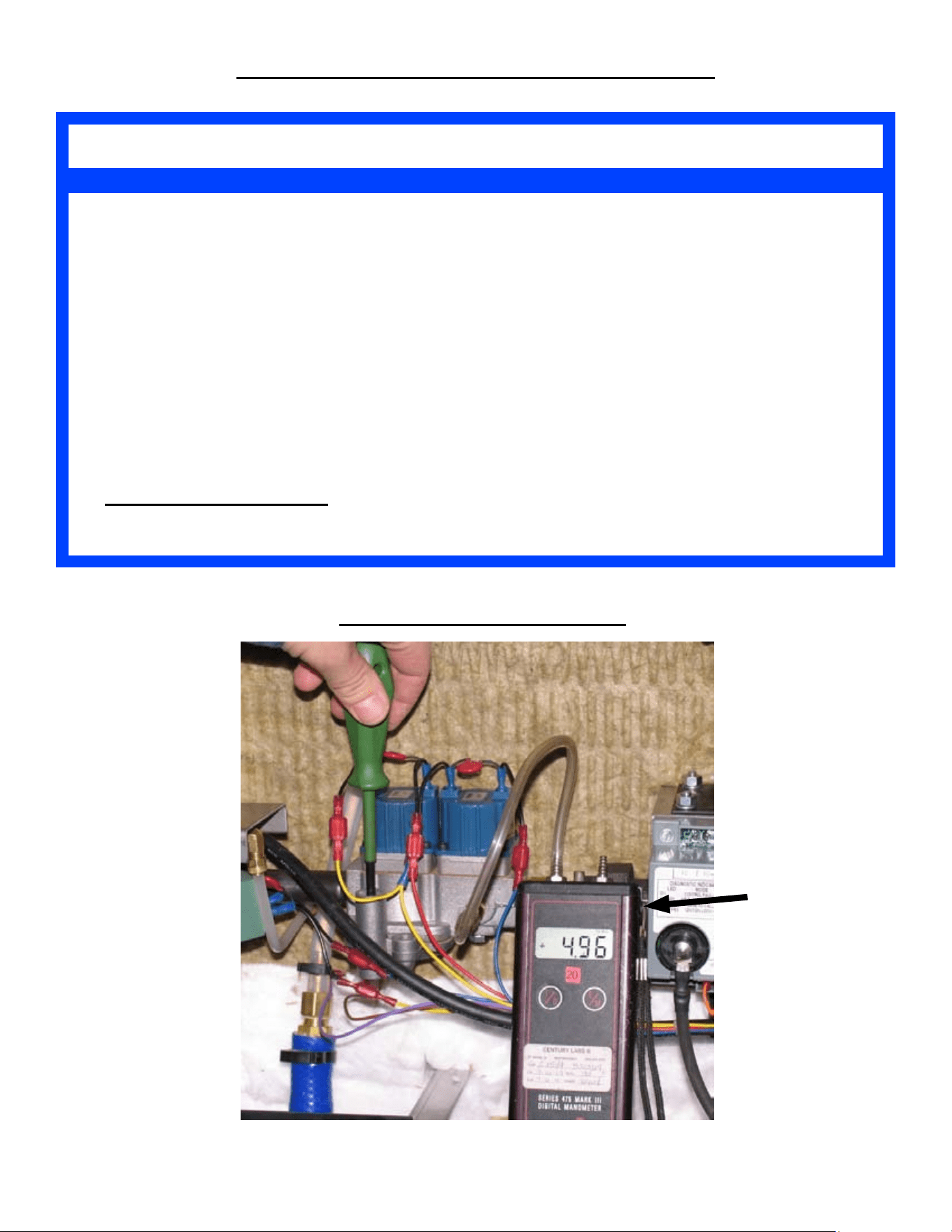
OPERATIONAL CONDITION NOTES
Measuring Gas Pressure Setup
Manometer
SP8026-1201 Pg 2

If the steamer’s gas burner is not igniting, ensure that you have veried and recorded
the following, prior to calling the AccuTemp Service hotline:
With the Gas Burner operating, the Water Column (WC) value of the gas pressure from the •
steamer’s Gas Control Valve is 5” WC = Natural Gas or 10” WC = Propane Gas.
The micro-Amp (µA) value of the Flame Sense Probe (Ignition Module pins FC+ & FC-) should •
have a minimum value of 2.5 µA .
If the steamer is not reaching temperature:
Ensure that the steamer is not in the HOLD Mode verses the COOK Mode. The default mode for •
the steamer, when the PWR button is turned ON, is COOK. So, if the operator presses the Timer
Button then the Cook/Hold button; the operator has just placed the steamer in the HOLD Mode
and the steamer will not reach 212°F (COOK Mode).
Ensure that the steam vent (located on the back of the steamer) is • not blocked or clogged. If the
customer has added an extended exhaust pipe, there’s an increased chance of vent blockage, if
the exhaust pipe is not installed properly. The exhaust pipe should be made of copper, galvanized
or stainless steel. The exhaust pipe should have a diameter of 3/4”; and be sloped 1/4” for every
12” of length (recommend a height no greater than 24”). Also, the addition of extra ttings that
can alter the gravitational ow of the steam condensation, can cause blockage. If vent blockage
does occur, it will cause the chamber pressure switch to stay open; which prevents the heater from
turning back on; and the temperature will continue to drop. Blocked vent can additionally cause
steam to blow out of the door.
Auto-Fill Steamer: If the steamer is overlling with water and causing the steamer to
shut-off:
Ensure the steamer is • level, front to back and side to side. An un-level steamer can cause the
water in the steam chamber to collect in the front of the steamer, causing the Over-Fill Float Ball
to raise and trip the Reed Switch prematurely (every time the steamer is turned ON). Once the
Reed Switch trips, it will cause an Over-Fill Light and Buzzer; while turning off the steamer and
preventing its usage.
Ensure that both of the Water Sensors are clean. Build-up of scale or crud will prevent the Water •
Sensors from providing the appropriate control signals to the Auto-Fill Valve, causing it to overll
with water.
Ensure that the water pressure being supplied to the Auto-Fill Valve should not be greater than •
60 psi. If water pressure is to high, then a larger volume of water will be added to the steam
chamber during the auto-ll cycle; causing the steamer to overll with water.
TROUBLESHOOTING NOTES
TROUBLESHOOTING NOTES
SP8026-1201 Pg 3
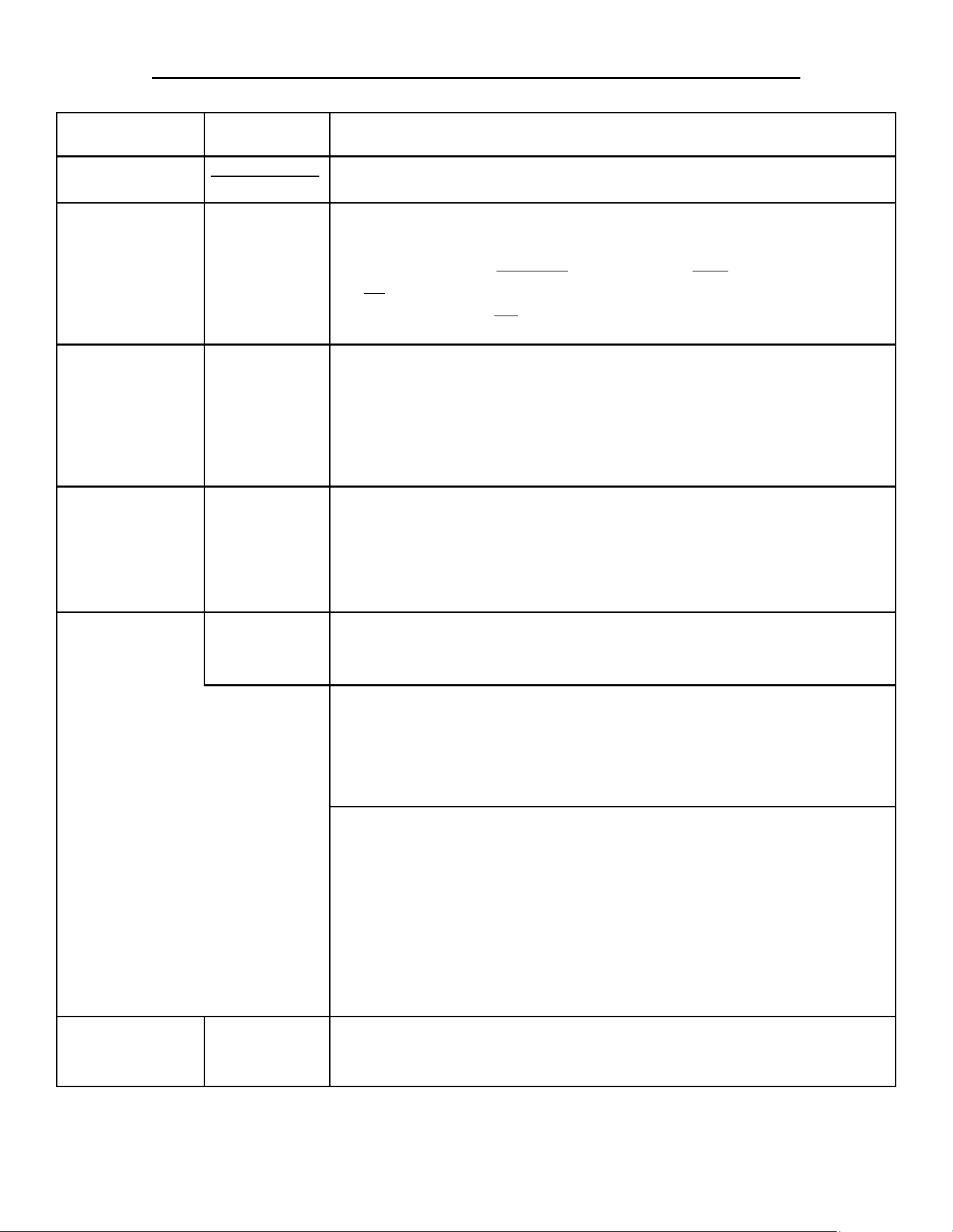
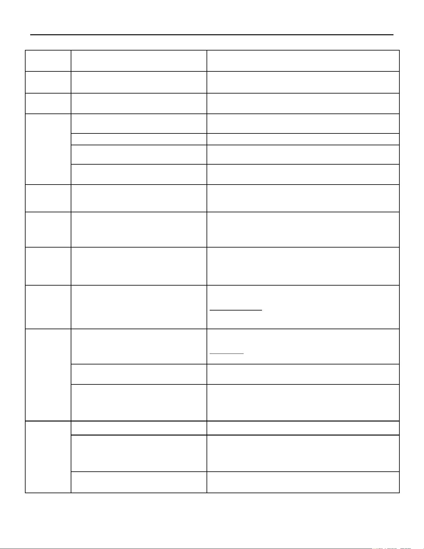
Component Part # Purpose
Transformer
Assembly Part#
AT0A-2779-3
Steps-down the Supply Line Voltage to 24 -28VAC.•
Overtemp Switch
(Thermal Limit
SW3)
AT1E-2653-4
Normally closed switch that provides a safety feature to the machine •
in case the Gas Heater overheats.
If the Gas Heater • overheats, the switch will open and turn the steamer
off; while lighting the red LED Overtemp Light on the Control Panel.
The steamer will • not turn on until the temperature has dropped
enough to allow the Overtemp Switch to close again.
Control / Keypad
Board
AT0E-3625-1
Human interface for steamer operations through push-buttons, •
operations, & display readouts.
Provides power to Control Relay #2 (24VDC).•
Receives input from the Temperature (RTD) Sensor and displays the •
water temperature on the LED readout.
Maintains the preset HOLD temperature.•
Water Sensor
Control Board
AT0E-3230-2
Receives inputs from Water Sensor Probes and implements •
corresponding actions for those inputs based on the water level in the
steam chamber.
Controls the Auto-Fill Valve (• if installed) and receives inputs that
provides actions for the desired water level needs.
Water Sensor
Probe
AT1E-2652-1
Teon exterior with a stainless steel center that uses the minerals in •
the water to complete the electrical circuit to the Water Board.
MUST BE CLEAN TO WORK PROPERLY.•
Low Water Level
Probe
Once the Low Water Sensor is satised, it will allow the Ignition •
Module to activate.
If the water level is below the sensor, the Water Board will activate •
the Auto-Fill Valve (if installed) lling the unit the water until the
High Limit Water Sensor is satised.
High Limit
Water Level
Probe
On initial chamber water ll, once the water level reaches and •
satises the Operational Water Sensor, the Water Board will keep the
Auto-Fill Valve open for 30 additional seconds..
After initial chamber water ll, when the water level drops below the •
sensor’s operational level; the Water Board will open the Auto-Fill
Valve for 30 seconds to raise the water level back above the High
Limit Water Sensor.
This process will repeat as long as the water level stays above the •
Low Water Sensor.
Auto-Fill Valve
(OPTIONAL)
AT1A-3841-1
Solenoid Valve that allows water to ow into the steam chamber; that •
is controlled automatically by the Water Board based on inputs from
the Water Sensor Probes.
PURPOSE REFERENCE OF MAIN COMPONENTS
SP8026-1201 Pg 4
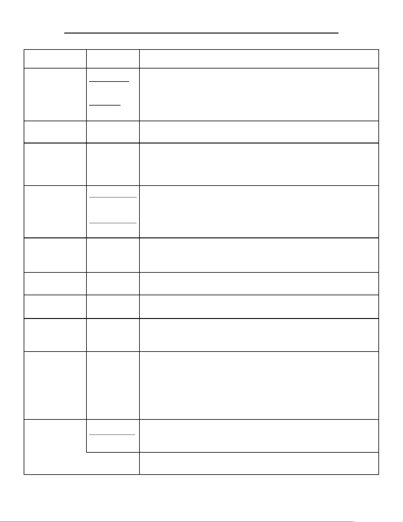
Component Part # Purpose
Water Over-Fill
Sensor Switch
(OPTIONAL)
Reed Switch:
AT0A-3519-3
Float Ball:
AT0P-3233-1
Magnetic Reed Switch is used in conjunction with a Float Ball. If the •
water rises too high, the switch opens and turns off the steamer.
When the switch opens, the High Water Overll LED will light. The •
user will have to drain the water out and turn the steamer back ON;
otherwise, the steamer will remain shutdown.
Control Relay #1
(AC)
AT0E-2825-5
Controls AC Volt input & output signals which provide actions from •
the Water Sensor Board and Auto-Fill Valve (if installed).
Door Switch AT0A-3660-1
Magnetic Switch used to ensure that the door is closed and latched •
prior to generating steam
Ignition Module will • not activate if this switch is not closed (Door
Open).
Chamber
Pressure Switch
S#: 34769 & Up
AT0E-3617-2
S#: 34768 & Lower
AT1A-3847
Normally closed switch that allows pressure to build-up inside the •
steam chamber.
Opens when the steam chamber pressure reaches 1/2 PSI.•
Ignition Module will • not activate if this switch is not closed (Switch
Open).
Time Delay
Relay #1
AT0E-2500-1
Normally open switch that closes after 5 seconds (once Door Switch •
& Chamber Pressure Switch are closed) to allow the Ignition Module
to activate and light the Gas Burner.
Control Relay #2
(DC)
AT0E-2825-6
Receives 24VDC (if the safety conditions are met) to the coil •
allowing the Ignition Module to activate the Power Burner Blower.
Power Burner
Blower
AT0E-3759-1
Provides the correct amount of air into the Gas Burner Box to allow •
the gas from the Gas Burner to ignite and burn efciently.
Blower Pressure
Switch
AT0E-3617-3
Closes once air pressure from the Power Burner Fan is applied.•
Ignition Module will • not activate if the switch is not closed (Switch
is Open due to no air from the Blower or the switch is defective).
Ignition Module AT0E-3760-1
Receives inputs and provides control signals to the Gas Control Valve •
and Gas Enrichment Valve.
Provides the voltage to the Ignitor Probe to ignite the gas from the •
Gas Power Burner.
Senses the input from the Flame Sense Probe (if there is a ame from •
the Burner or not) and makes appropriate control signal outputs based
if there is a ame from the burner or not.
Ignitor Probe
Assembly Part#
AT1E-3795-1
Uses high voltage, supplied by the Ignition Module, to form a spark •
between the Ignitor Probe and the GND Probe.
Ignites the gas/air mixture from the Gas Power Burner.•
Flame Sense
Probe
Veries that a ame is present and if no ame is sensed; the Ignition •
Module will go into lockout and deactivates all gas valves.
PURPOSE REFERENCE OF MAIN COMPONENTS
SP8026-1201 Pg 5
Component Part # Purpose
Time Delay
Relay #2
AT0E-2500-2
Closes for 4 seconds, on initial start-up, to allow the Gas Enrichment •
Valve to open; providing a high concentration of gas to help ignite
poor quality gas on cold start-ups.
Gas Enrichment
Valve
AT0P-3818-1
Used to provide a richer concentration of gas to the Burner on cold •
start-ups. Helps to compensate for poor quality supplied gas.
Controlled by Time Delay Relay #2 and the Ignition Module.•
Gas Control
Valve
Natural Gas:
AT2E-1806-2
Propane Gas:
AT2E-1806-3
Controls and maintains a constant ow of gas to the Gas Power •
Burner.
Controlled by the inputs from the Ignition Module.•
Gas Orice
Natural Gas:
AT0B-3758-1
Propane Gas:
AT0B-3758-2
Provides the correct ratio of gas volume and pressure to the burner via •
a preset diameter hole size.
Orice Size for • NG: .1360 & for PG: .0935
Gas Power
Burner
AT1A-3768-1
Dispenses the mixture of gas and air evenly over its surface to •
provide maximum ame and heat dispersal efciency.
Gas Power
Burner Box
AT1A-3769-1
Chamber that positions the Burner and contains the ue gasses •
produced from the bunrer’s ame.
Temperature
(RTD)
Sensor
AT0E-3626-1
Provides temperature input to Control/Keypad Board, which displays •
the temperature in the steam chamber based on resistance changes
from the Temperature (RTD) Sensor.
Used to maintain the preset HOLD mode temperature.•
Door Assembly AT1A-3600-1
Keeps the steam trapped inside the steam chamber to allow pressure •
to build and cycle the Chamber Pressure Switch.
Drain Valve AT1P-2239-1
Manually Open/Close valve used to drain water from the steam •
chamber.
PURPOSE REFERENCE OF MAIN COMPONENTS
ADDITIONAL COMPONENT PART NUMBERS
Component Part # Component Part #
Pilot Lamp, 24V Red AT0E-1800-2 Inner Door Assembly AT1A-3647-1
Fuse, Slo-Blo 3A AT0E-2731-1 Door Hinge (Pair) AT1H-2058-3
Ignition Cable AT0E-3810-1 Door Latch Assy, Ceramic Magnet AT1H-3609-1
Gasket, Door AT1G-2633-1 Door Latch Mounting Plate AT1M-3046-1
SP8026-1201 Pg 6

MANUAL FILL:
Power Cord Plugged-In & PWR Button Not Pushed
Line Voltage (120/240VAC) comes in through the Terminal Strip and 3A fuse until it reaches •
the Transformer.
Line Voltage is also applied to the Ignition Module on pin L1, after it goes through the 3A •
fuse.
The Transformer steps-down the Line Voltage to 24VAC and applies that, through the •
Overtemp Switch & Overll Reed Switch (Auto-Fill Only), to the Water Sensor Board, the
Control/Keypad Board, and Ignition Module on pin V2.
(The red LED light on the Water Sensor Board will be ashing at a rapid rate.)•
The AC coil of Control Relay #1 (CR#1) is energized.•
PWR Button Pushed & Water Level Is Below the Low Water Level Sensor
PWR Button pushed and the Low Water Light Indicator will be ON and Alarm will sound.•
(The red LED light on the Water Sensor Board will continue to ash at a rapid rate.)•
PRE• is displayed on the Control/Keypad Board.
PWR Button Pushed & Water Is Filled to the Water Level Mark
PWR Button pushed and the Low Water Light Indicator will be OFF and no Alarm will •
sound, due to the Low Water Level Sensor being satised. (The red LED light on the Water
Sensor Board will have a 1 second ash rate.)
Low Water Sensor’s signal will close the Water Sensor Control Board’s K2 Relay, which will •
turn-off the Low Water Light and send a power signal to pin 5 of Control Relay #2 (CR#2),
pin 24VAC of the Ignition Module, and the Gas Control Pilot Valve.
The Control/Keypad Board will send a 24VDC signal to Control Relay #2 closing the DC •
coil (as long as the Door Switch and the Chamber Pressure Switch is closed; allowing the
Time Delay Relay #1 to close after a 5 second delay, which will create a buffer for power to
the DC coil).
Control Relay #2’s DC coil is closed, allowing the power signal from K2 Relay to pass from •
pin 5 to pin 3 of Control Relay #2; sending power to the Ignition Module on pin TH.
(If the Gas Power Burner • does not ignite, the Ignition Module will look-out; and the steam-
er will have to be turned OFF and back ON to get the steamer to try and re-light the Gas
Power Burner.)
SEQUENCE OF OPERATION
SP8026-1201 Pg 7

MANUAL & AUTO-FILL:
Ignition Module
Power signal to the Ignition Module’s pin TH, activating the Power Burner Fan from pin •
IND on the Ignition Module.
Air pressure from the Power Burner Blower will close the Power Burner Blower Pressure •
Switch, supplying power to pin PSW.
Ignition Module will send control signals from pin V1 to the Time Delay Relay #2, and to •
the Gas Control Main Valve. At the same time, Ignition Voltage is sent to the Ignitor Probe
creating a spark between the probe and GND.
The Time Delay Relay #2 operates for 4 seconds, allowing the Gas Enrichment Valve to •
supply a dense amount of gas (compensation for poor quality source gas), in conjunction
with the Gas Control Valve’ gas.
The Ignition Module will look for a signal from the Flame Sense Probe, via pin S1, to •
indicate taht the gas was lit and burning a ame. If no ame is sensed within 4 seconds of
ignition start, then the Ignition Module will lockout and prevent the steamer from operating.
Gas Power Burner & Heat Transfer
When the Gas Enrichment and Gas Control Valves are opened, gas is sent through the Gas •
Orice and mixed with air from the Power Burner Fan; then it is distributed through the Gas
Burner’s surface ports to be ignited by the Ignitor Probe’s spark.
Flame Sense signal will cause the Ignition Module to keep the Gas Control Valve open, •
supplying gas to the burner. (The ame should be a blue color for maximum efciency.)
The heat generated in the Gas Burner Box will be transferred, by the Heat Transfer Plate, •
evenly over the bottom of the steam chamber; boiling the water inside to create steam for
cooking.
Temperature Sensor (RTD) and Control/Keypad Board
As the temperature rises in the steam chamber, the RTD will provide a signal, based on the •
resistance of heat variance, to the Control/Keypad Board to provide a digital Temp Display.
Control Panel will show • PRE on initial heat-up until the steam chamber reaches 195°F; then
COO will be display between 195°F and 212°F.
The operating default mode on initial power ON is COOK mode; which causes the steamer •
to go to the operating temperature of 212°F.
In HOLD mode; the steamer’s temperature is displayed on the Control Panel until the HOLD •
temperature’s preset value is reached; then HLD is displayed. The Control/Keypad Board
will regulate temperature via the RTD input, based on that HOLD preset value. (This value
can be changed using the program function on the Control/Keyboard Control.)
SEQUENCE OF OPERATION
SP8026-1201 Pg 8

AUTO-FILL (OPTIONAL):
Power Cord Plugged-In & PWR Button Not Pushed
Same as Manual Fill.•
PWR Button Pushed & Water Level Is Below the Low Water Level Sensor
PWR Button pushed and the Low Water Light Indicator will be lit.•
(The red LED light on the Water Sensor Board will be ashing at a rapid rate.)•
The Water Sensor Board sends a signal to the Water Sensor Board’s K1 Relay to open the •
Auto-Fill Valve and start lling the steam chamber with water.
(This process will continue every time the water level falls below the Low Water Level •
Sensor.)
PWR Button Pushed & Water Level Is At the Low Water Level Sensor or Above
Same as Manual Fill.•
Water Level Is At the High Limit Water Level Sensor
When the water level reaches the High Limit Water Level Sensor, the Water Sensor Board •
will continue to activate the Auto-Fill Valve for 30 seconds then turn it off.
(The red LED light on the Water Sensor Board will have a 2 second ash rate.)•
This process will continue every time the water level falls below the High Limit Water Level •
Sensor.
Water Level Is Filled Too High in the Steam Chamber
When the water level gets to high in the steam chamber, the Float Ball will rise on the Reed •
Switch sensor peg until the Reed Switch does not read the magnetic eld from the Float Ball.
This will cause the Control Relay #1 AC coil’s voltage to drop, dis-engaging the relay from •
the steamer’s normal operation; and also lighting the High Water (Over-Fill) Indicator Lamp
on the Control Panel.
Loss of Control Relay #1 cause the loss of the control signal to pin 5 of Control Relay #2; •
causing it to turn off the Ignition Module and close the Gas Control Valve which stops the
gas feed to the Gas Power Burner.
(To restart the steamer, drain the water out until the High Water (Over-Fill) Indicator Light •
turns-off. Pressing the PWR button ON will begin the start-up procedure.)
SEQUENCE OF OPERATION
SP8026-1201 Pg 9
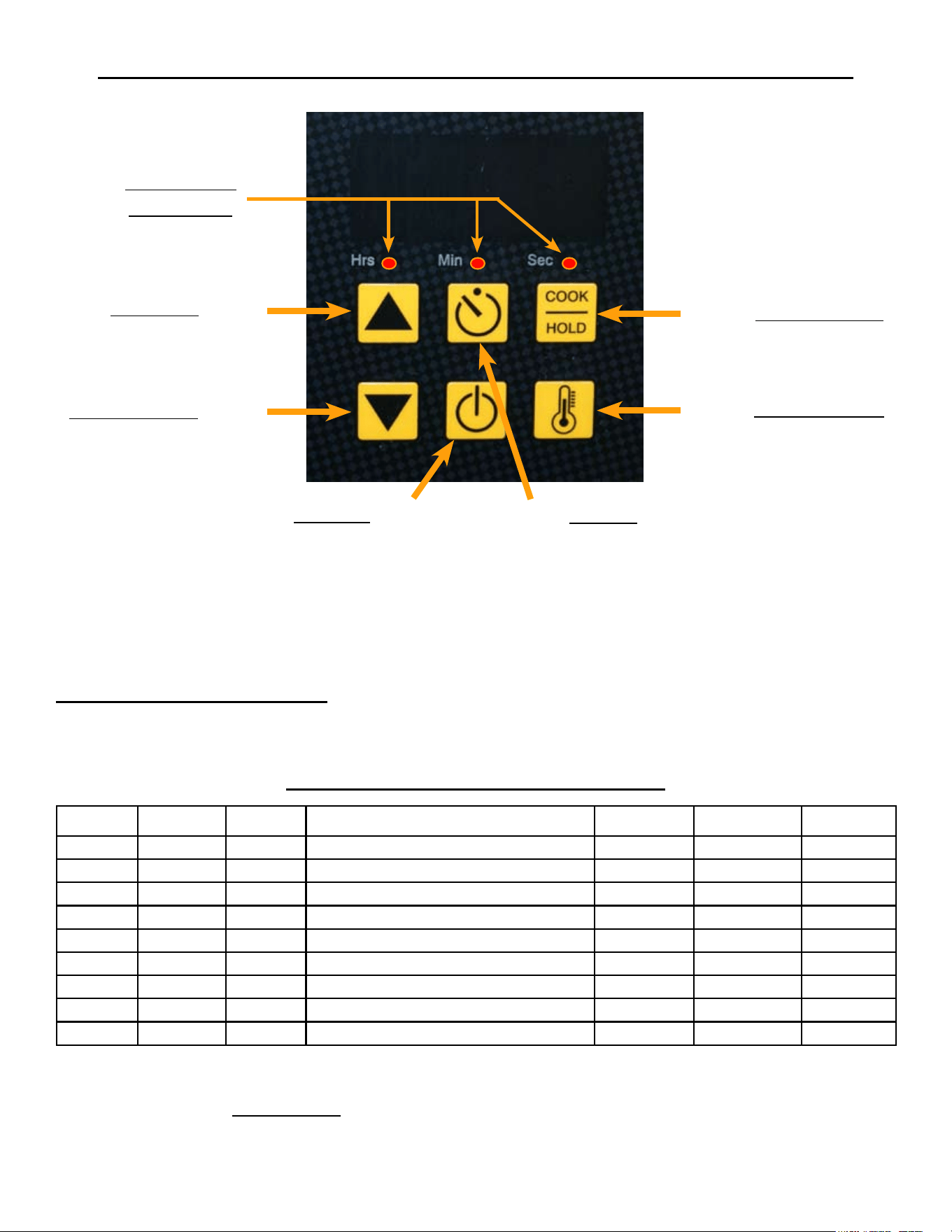
S1
S6
S3
UP Arrow
S4
DOWN Arrow
TEMP Display
COOK/HOLD
S5
POWER
S2
TIMER
Hrs/Min/Sec
LED Lights
S1 - Increase Program Item (Will cycle the Hrs/Min/Sec LED light)
S4 - Decrease Program Item (Will cycle the Hrs/Min/Sec LED light)
S3 - Increase Program Value (Will change the Digital Readout display)
S6 - Decrease Program Value (Will change the Digital Readout display)
S2 - Exit & Save
ENTERING PROGRAM MODE: Simultaneously, depress and hold S4 & S6 for minimum of 8 seconds or
until the Hrs LED blinks and the display shows a Hold Temp number (default is 180°F). Now the Controller
can operate under the Program Function Parameters.
Hrs LED Min LED Sec LED PARAMETER MIN MAX GAS
Blink OFF OFF HOLD Temp Value = Degree F MIN Temp MAX Temp 180
ON OFF OFF Default Timer Value = Hours 0 8 0
OFF ON OFF Default Timer Value = Minutes 0 59 30
OFF OFF ON TEMP Probe Offset = Degree F 0 50 0
ON ON ON TEMP Probe Offset = Neg/Pos Diff NEG = 1 POS = 0 0
Blink Blink Blink Hysteresis
2 10
3
ON Blink Blink TEMP Regulating Mode
On/Off = 0 PID = 1
0
Blink ON Blink Proportioning BAND TIME 4 10 10
Blink Blink ON Proportioning BAND WIDTH 4 10 10
Program Mode Function Parameter Table
RESETTING CONTROLLER TO FACTORY DEFAULT VALUES ON THE GAS STEAMER
CAN CAUSE AN IGNITION MODULE CONTROL FAULT.
MODIFYING CONTROL / KEYPAD PROGRAM SETTINGS
SP8026-1201 Pg 10
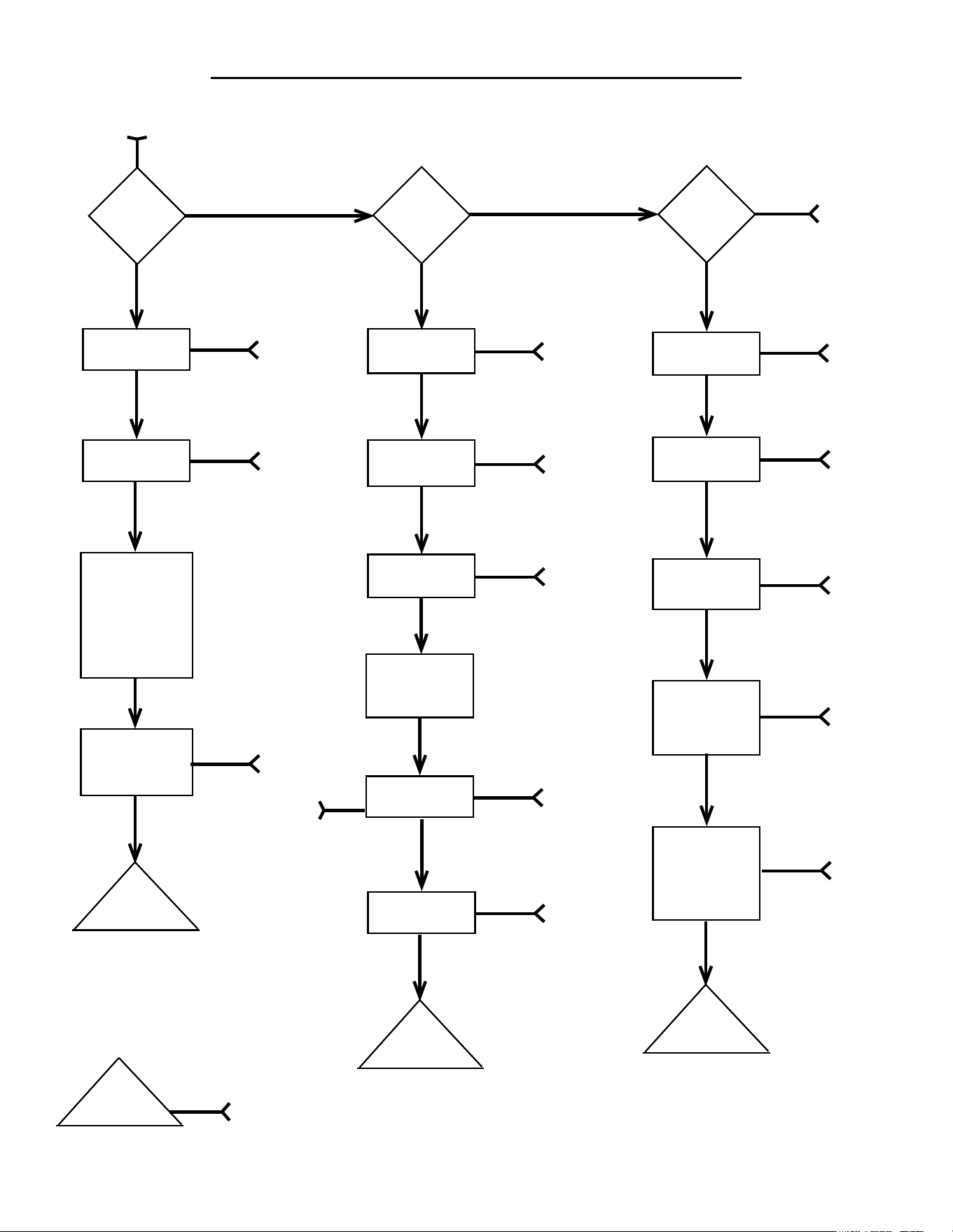
TROUBLESHOOTING FLOW-DIAGRAM
SP8026-1201 Pg 11
Call
AccuTemp
Service
(800) 480-0415 or [email protected]
NO
Steamer
Plugged-In
NO
SEE
A
YES
Breaker
ON
NO
SEE
B
YES
Control Panel
Error Code
YES
SEE
E
Low Water
Light
NO
YES
SEE
F
Different
Problem
With
Steamer
Operations
DONE
WITH
CHART
NO
YES
Temp
Low
YES
YES
SEE
J
Food Over
Cooked
NO
YES
SEE
L
Steam Out
The Door
NO
YES
SEE
K
Food
Under
Cooked
NO
YES
SEE
M
YES
START
POWER
ON
YES
Check
Internal
Power
Voltages
SEE C
Component
Voltages
Correct
NO
SEE
D
YES
Call
AccuTemp
Service
NO
Over Temp
Light
YES
SEE
G
NO
Call
AccuTemp
Service
YES
Call
AccuTemp
Service
NO
WARNING
LIGHTS
NO
SEE
I
STEAMER
HEATING
High Water
(Over-Fill)
Light
NO
Float Ball
Installed
YES
SEE
H
YES
Ball
Float Ball
Present
YES
SEE
Ball
NO
FLOW-DIAGRAM REFERENCE TROUBLESHOOTING CHART
SP8026-1201 Pg 12
REF
LETTER
POSSIBLE CAUSE EVALUATION
A
Power Cord Disconnected
Conrm proper voltage is present at receptacle.
Plug-in Power Cord.
B
Breaker Is Tripped
Unplug steamer and check line voltage at plug-in receptacle.
Reset Breaker.
C
Transformer
Check for proper incoming line voltage to the primary side and
24VAC on the secondary side.
Fuses Check for blown fuses.
Over-Temp Switch
Check between the common wire, terminal # 6 on the Control
Relay #1 and the brown wire after the fuse.
Control panel not responding.
Check for 24VAC incoming power at pins J2-1 & J2-2.
Check for out put at pins J7-3 & J7-4 (ON/OFF) = 24VAC
D
Bad Component or Faulty Wiring
Check the wiring to the component; including wire-to-
connectors, GND’s, and damage.
If a component output is bad, then it may need replaced.
E
Error Code: -1F or -99F for
Temperature (RTD) Probe.
Check for 1000 ohms (at room temp) on Control/Kepad Board on
J3 - Pins 1 & 2.
EC: -1F = Open Temp (RTD) sensor
EC: -99F = Shorted Temp (RTD) sensor
F
Low Water Sensor Not Satised
Ensure water level is above Low Water Sensor Probe inside the
steam chamber.
Ensure that the Low Water Sensor is cleaned and that the Water
Board is working properly.
G
Steamer Has Over-Heated
Check that the water level inside steam chamber is not empty; and
rell if needed.
If an Auto-Fill unit, then ensure that water supply is not shut-off, or
Auto-Fill Valve is faulty.
Ensure Water Sensors are clean.
H
Too Much Water In Steam Chamber
DO NOT OPEN DOOR!
Open Drain Valve until the High Water Light goes off. If light
DOES NOT go out and no water in steamer, then possibly a sensor
fault.
Operational Water Level Sensor Faulty
Ensure the top Water Sensor is clean.
Check that Water Board is working properly.
Float Ball & Reed Sensor Faulty
Ensure Float Ball is not stuck on the Sensor Post.
Ensure Sensor Post & inside of the Float ball are clean.
Check continuity of the Reed Switch (Float over sensor creates
continuity; the Float off the sensor is open.)
I
Control/Keypad Panel Check for 24VDC output (J7 Pins 1 & 2).
Door Switch Not Engaging
Ensure Door is shut and handle is latched.
Check the Door Switch for continuity with Door closed.
Check the butt splices and wire connection terminals for good
crimps.
Chamber Pressure Switch
Switch is normally closed.
Check the Chamber Pressure Switch for continuity.
FLOW-DIAGRAM REFERENCE TROUBLESHOOTING CHART
SP8026-1201 Pg 13
REF
LETTER
POSSIBLE CAUSE EVALUATION
I
Time Delay Relay #1 (5 sec)
Relay is normally open.
Check for continuity during the rst 5 -10 seconds of pressing
PWR ON button.
Control Relay #2
Check for 24-30VDC at Pins 7 & 8 on the CR2 Coil.
Check for 24VAC on pin 3.
Ensure Relay Contacts are closing and not stuck open.
Blower Pressure Switch
Switch is normally open.
Check that switch closes at .2” Water Column (WC) & that voltage
is present on Lt Blue wire to Ignition Module at pin PSW.
Power Burner Blower
Check that the vent is set for:
3” for Natural Gas & 3” for Propane.
If vent is to large, then unit will not ignite.
Ignition (Spark) Module
Check the Red LED light on the module for the
following indications (listed on the module):
Constant = Control Fault (Turn unit OFF & back
ON, if LED goes out; then ignition module is OK.)
1 Flash = Air Vent Blockage / No Blower Pressure
2 Flashes = Flame with No Call For Heat
3 Flashes = Ignition Lookout (No Gas Present)
Ignition Probe & Cable
Check that the probes are not oxidized or broken.
Check that the Ignition Cable has a good connection to Ignition
Probe.
Verify that the Ignition Probes are in the correct position to the
Burner’s surface as required.
Gas Enrichment Valve
Check to ensure that the Time Delay Relay #2 is
opening the Gas Enrichment Valve for 4 seconds.
(Signal from Spark Module out of pin V1.)
Gas Valve Control
Ensure that the valve is engaging.
Check that the Gas Pressure is at the correct WC value:
5” for Natural Gas & 10” for Propane.
External Supply Gas Press. Regulator
Verify that the incoming gas pressure from the External Regulator
is between WC values:
7” - 10” Natural Gas & 11” - 13” Propane.
Steam Vent Blocked
Steam should be coming out of vent at back of steamer.
Check for blockage in the vent, which can cause the Chamber
Pressure Switch to open.
Ensure that there is at least a minimum of 1/4” slope for every foot
added, of extended exhaust piping.
Ensure that any extended exhaust piping is made of galvanized or
stainless steel, or copper; and a minimum of 3/4” in diameter.
If blockage is present, try to pour some hot water down the vent
piping to unclog the blockage (may have to blow out the blockage
if water doesn’t help).
J
Steam Temperature Is Not At
Desired Cook Temperature
Check that the Door is closed and no steam is escaping from it.
Verify that Low Water indicator light is not lit.
Check that steamer is in the COOK mode and NOT in the HOLD
mode.
FLOW-DIAGRAM REFERENCE TROUBLESHOOTING CHART
SP8026-1201 Pg 14
REF
LETTER
POSSIBLE CAUSE EVALUATION
J
Steam Vent Blocked
See Ref Letter I.
K
Door Assembly
Check to see if the Door is seating completely around the face of
the Steamer.
Check that the Door Gasket does not have any cuts, nicks, debris,
or discolorations (white or grey).
Pressure Switch
Check that the Chamber Pressure Switch opens and closes
checking the Ohms reading while blowing into its input hose.
(Disconnect the hose from the chamber inlet hole.)
Steam Vent Blocked
See Ref Letter I.
L
Food Cook Time Too Long
Ensure that the proper Cook Time is being used.
Refer to the Owners Manual for cooking tips if no mechanical
reason is found for this symptom.
M
Food Cook Time Not Long Enough
See Ref Letter K.
Ensure that the steamer is in the COOK mode and not the HOLD
mode. (HOLD has a preset temp value that is below that of
212°F.)
Check that proper pan placement is being utilized for best cooking
conditions. (See Owners Manual)
Ensure that the Drain Ball-Valve is shut tightly or possible loss of
heating efciency.
Refer to the Owners Manual for cooking tips if no mechanical
reason is found for this symptom.
If your symptoms are not listed in the Flow Chart and/or the REF Chart, then
additional troubleshooting may be required.
If you need additional ideas for troubleshooting or want to conrm your symptoms
with one of our Service Techs, please contact us by phone or e-mail listed below
with the unit’s S/N or Model information.
AccuTemp Service Dept. Phone (800) 480-0415
AccuTemp Service Dept. Email [email protected]
NOTE
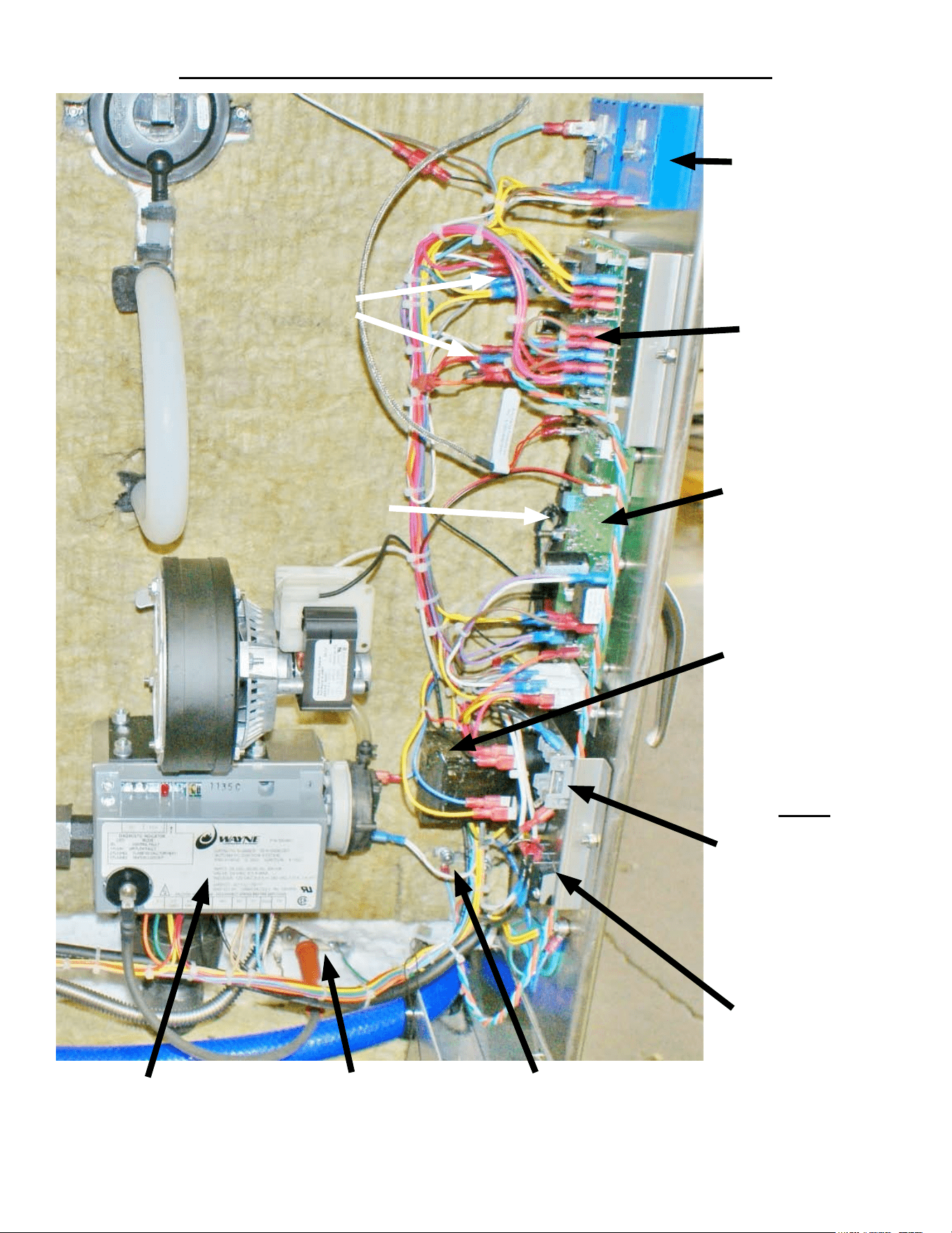
LOCATION OF ELECTRICAL COMPONENTS
SP8026-1201 Pg 15
Control Relays
Door Close Switch
Time-Delay
Relays
Water Sensor
Control Board
Control / Keypad
Board
Fuses
1 Fuse = 120VAC
2 Fuses = 240VAC
Power Cord
Terminal Strip
Water Sensors
Transformer
Ignitor / Flame Sense
Probe
Ignition Module
ELECTRICAL COMPONENTS REMOVAL & INSTALLATION
SP8026-1201 Pg 16
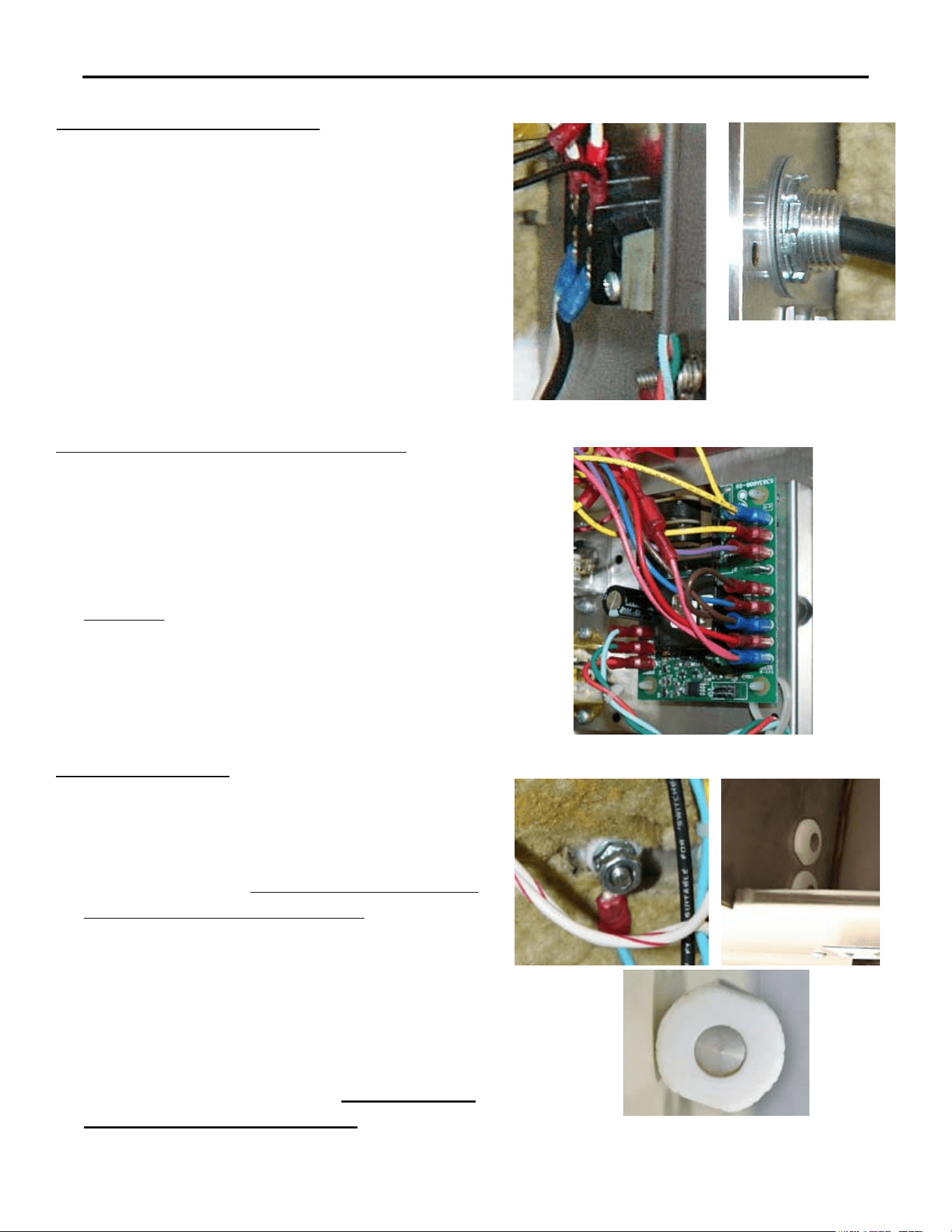
CORD & PLUG ASSEMBLY
Unplug the Unit.1.
Remove the Left-Side Panel by removing the 2.
Sheet Metal Screws holding it in place.
Disconnect the Power Cord Leads (Black, 3.
White, Red, and/or Green) from the Terminal
Strip.
On the inside of the unit, remove the retaining 4.
nut on the threads of the Power Cord Cable
Fitting & pullout the Power Cord.
Re-install in reverse order.5.
WATER SENSOR CONTROL BOARD
Unplug the Unit.1.
Remove the Left-Side Panel by removing the 2.
Sheet Metal Screws holding it in place.
Disconnect the wires (note the wire color to its 3.
location pin).
Carefully4. , push in the locking leg on the 4
plastic posts while pulling the Water Board up
off the posts (note the board’s orientation).
Remove the Water Board.5.
Re-install in reverse order.6.
WATER SENSORS
Unplug the Unit.1.
Remove the Left-Side Panel by removing the 2.
Sheet Metal Screws holding it in place.
Open the door and 3. ensure that all the water is
drained from the steam chamber.
Disconnect the wire from the backside of the 4.
Water Sensor (access via left-side panel).
Remove the retaining nut that mounts the Water 5.
Sensor to the Steam Chamber.
Push the Water Sensor through the hole in the 6.
steam chamber from the backside.
Re-install in reverse order. 7. Torque Sensor
Nuts to between 12-15 In-Lbs.
ELECTRICAL COMPONENTS REMOVAL & INSTALLATION
SP8026-1201 Pg 17
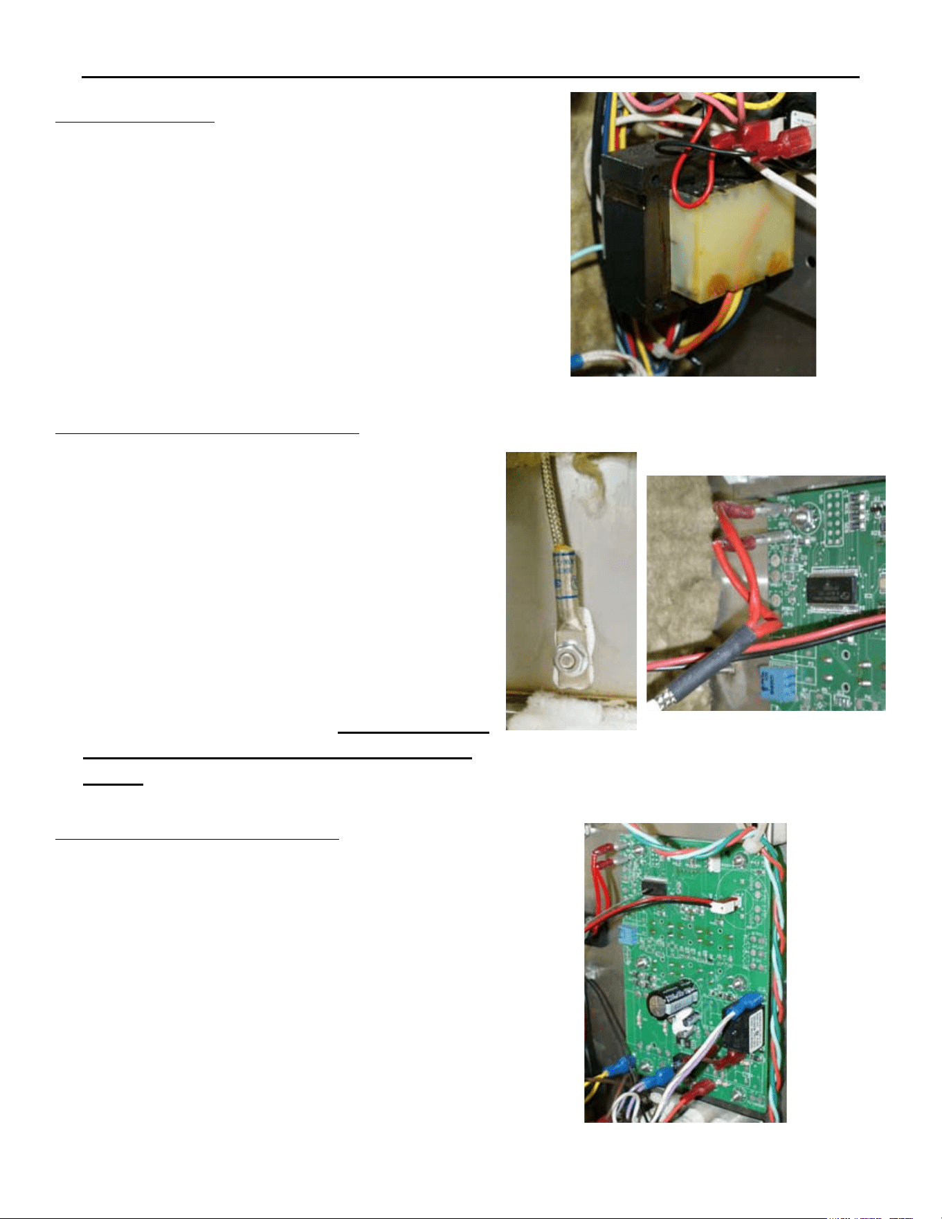
TRANSFORMER
Unplug the Unit.1.
Remove the Left-Side Panel by removing the 2.
Sheet Metal Screws holding it in place.
Disconnect the wires (note the wire color to its 3.
location terminal).
Remove the 2 mounting nuts and then remove 4.
the Transformer.
Re-install in reverse order.5.
CONTROL / KEYPAD BOARD
Unplug the Unit.1.
Remove the Left-Side Panel by removing the 2.
Sheet Metal Screws holding it in place.
Disconnect the wires (note the wire color to its 3.
location terminal).
Remove the 7 mounting nuts and then remove 4.
the Control Panel CCA.
(5. If accessing the Program Mode is needed, go
to page 10 for more details.)
Re-install in reverse order.6.
TEMPERATURE (RTD) SENSOR
Unplug the Unit.1.
Remove the Left-Side, Right-Side, and Top 2.
Panel by removing the Sheet Metal Screws
holding it in place.
Disconnect the probe wires from the Control/3.
Keypad Panel and pull them from the left, over
the top, to the steamer’s right-side (the wires
to the location pins are enter-changeable).
Remove the mounting nut and then remove the 4.
Temperature (RTD) Sensor.
Re-install in reverse order. 5. Ensure Thermal
Paste is applied to the Temperature (RTD)
Sensor.
ELECTRICAL COMPONENTS REMOVAL & INSTALLATION
SP8026-1201 Pg 18
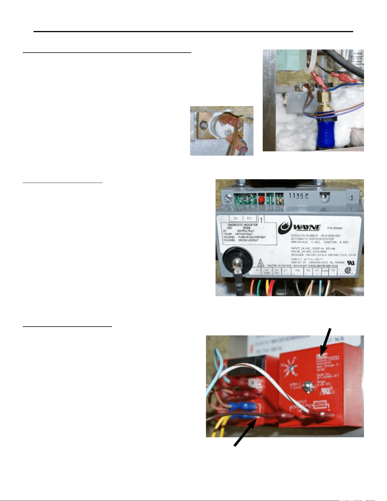
OVERTEMP SWITCH (THERM LIMIT SW3)
Unplug the Unit.1.
Remove the Left-Side Panel by removing the 2.
Sheet Metal Screws holding it in place.
Disconnect the wires (note the wire color 3.
to its location pin).
Remove the 2 mounting screws and then 4.
remove the Overtemp Switch.
Re-install in reverse order.5.
IGNITION MODULE
Unplug the Unit.1.
Remove the Left-Side Panel by removing the 2.
Sheet Metal Screws holding it in place.
Remove the mounting nut on the Ignition 3.
Cable.
Disconnect the wires (note the wire color to its 4.
location pin).
Remove the 2 mounting screws and then 5.
remove the correct voltage type Control Relay.
Re-install in reverse order.6.
TIME-DELAY RELAYS
Unplug the Unit.1.
Remove the Left-Side Panel by removing the 2.
Sheet Metal Screws holding it in place.
Disconnect the wires from the desired 3.
Time-Delay Relay (note the wire color to its
location pin).
Remove the mounting nut and then remove 4.
the desired Time-Delay Relay.
(5. Ensure the time-delay pot is set to the correct
delay time...TDR#1 = 5sec / TDR#2 = 4sec).
Re-install in reverse order.6.
TDR #2 (4sec)
TDR #1 (5sec)
ELECTRICAL COMPONENTS REMOVAL & INSTALLATION
SP8026-1201 Pg 19
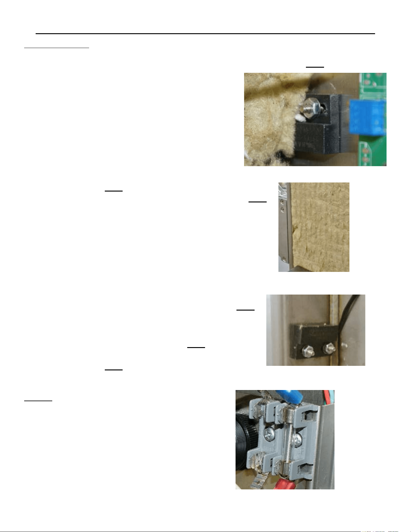
CONTROL RELAYS
Unplug the Unit.1.
Remove the Left-Side Panel by removing the 2.
Sheet Metal Screws holding it in place.
Disconnect the wires (note the wire color to its 3.
location pin).
Remove the 2 mounting screws and then 4.
remove the correct voltage type Control Relay.
Re-install in reverse order.5.
AC Relay
CR1
DC Relay
CR2
IGNITOR & FLAME SENSE PROBE
Unplug the Unit.1.
Remove the Left-Side Panel by removing the 2.
Sheet Metal Screws holding it in place.
Disconnect the wires from the probes (note the 3.
wire to its probe location).
Remove the 2 mounting bolts and then remove 4.
the Probe Assembly.
Re-install in reverse order. 5. Ensure that the
GND Probe is angled towards the Burner’s
Surface.
Ignition
Probe
Ignition
Probe
Flame
Sense
Probe
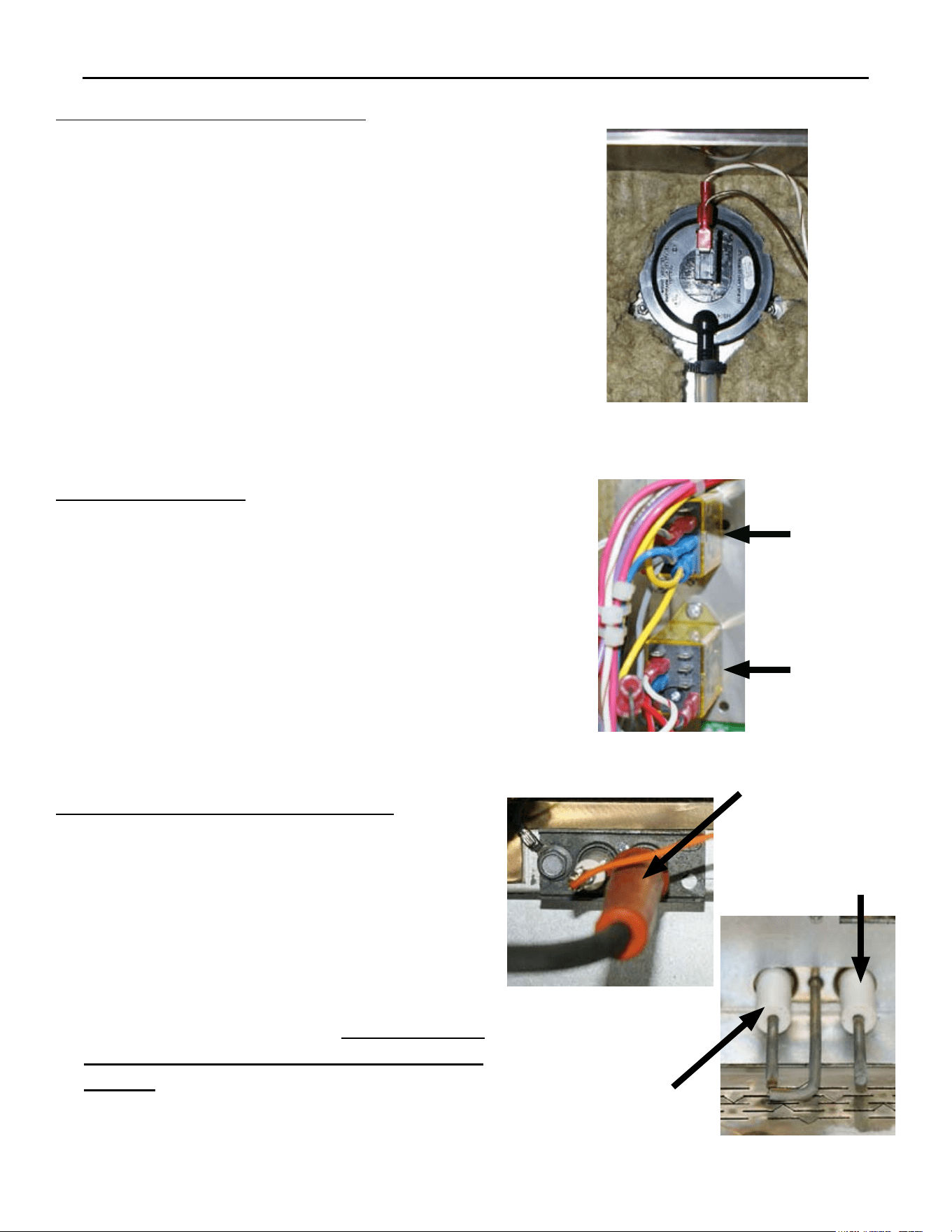
CHAMBER PRESSURE SWITCH
Unplug the Unit & remove the Left-Side Panel 1.
by removing the Sheet Metal Screws holding it
in place.
Disconnect the Wiring Terminals from the 2.
Chamber Pressure Switch (note the wire color
to its location terminal).
Remove the hose clamp and disconnect the 3.
hose from the Chamber Pressure Switch.
Remove the 2 mounting nuts holding the 4.
Chamber Pressure Switch to chamber cavity.
Remove the Chamber Pressure Switch5.
Re-install in reverse order.6.
ELECTRICAL COMPONENTS REMOVAL & INSTALLATION
SP8026-1201 Pg 20
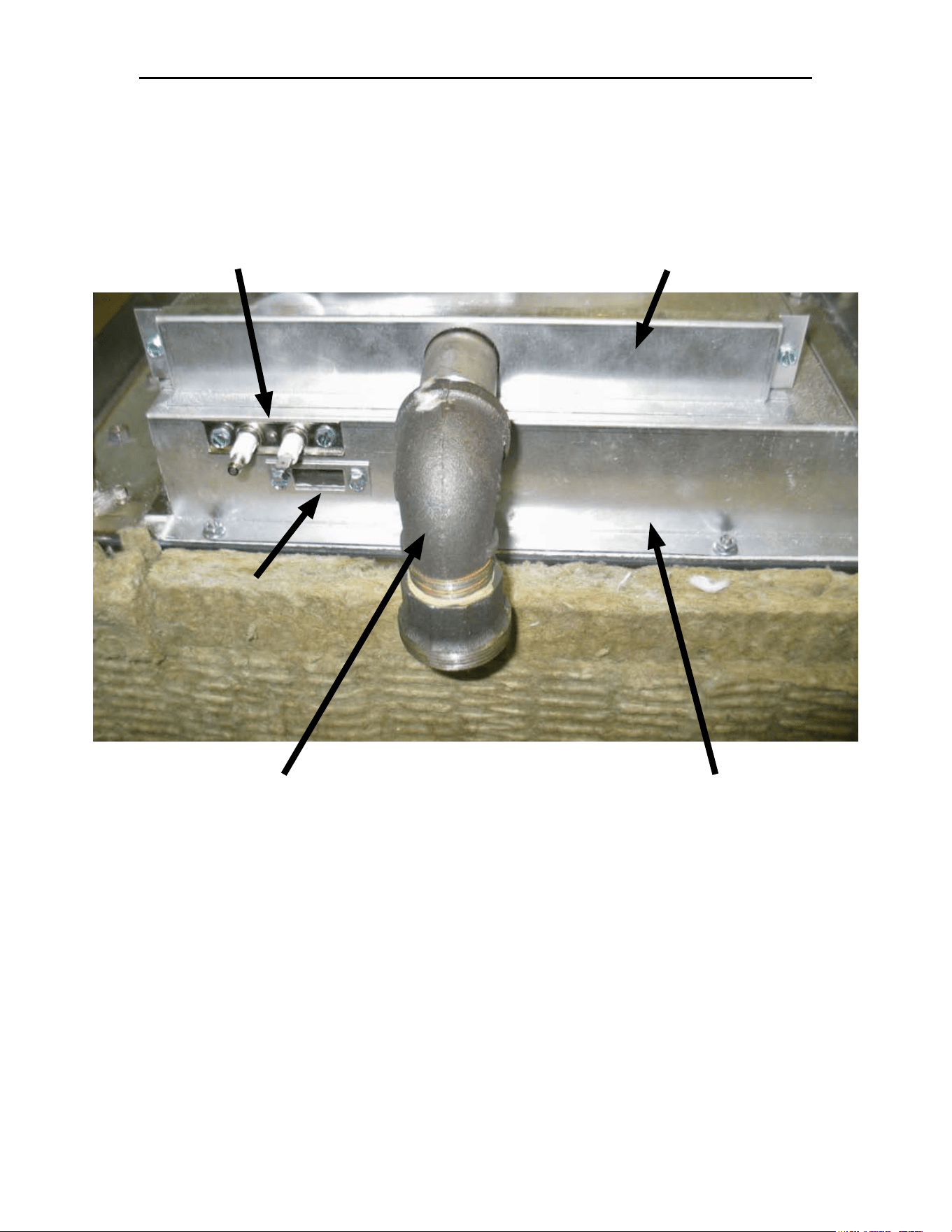
DOOR SWITCH
Door Latch on the Left-Hand Side
Unplug the Unit.1.
Remove the Left-Side Panel by removing the 2.
Sheet Metal Screws holding it in place.
Disconnect the probe wires: Control/Keypad 3.
Panel J7 Pin 1 & the White/Brown wire from
the Chamber Pressure Switch (the wires to the
location pins are enter-changeable).
Push back the insulation, so you can access the 4.
other mounting nut to be removed.
Remove the 2 mounting nuts and then remove 5.
the Door Switch. Fg 1
Re-install in reverse order.6.
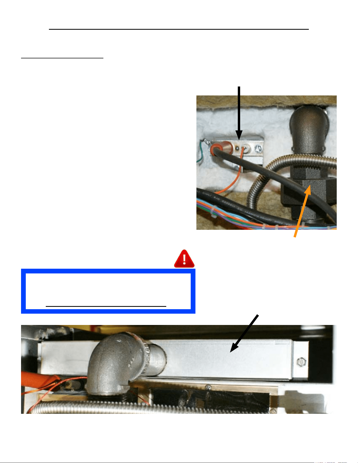
Door Latch on the Right-Hand Side
Unplug the Unit.1.
Remove the Left-Side, Right-Side, and Top 2.
Panel by removing the Sheet Metal Screws
holding it in place.
Disconnect the probe wires: Control/Keypad 3.
Panel J7 Pin 1 & the White/Brown wire from
the Chamber Pressure Switch; and pull the
wires up, over the top of the steamer (the wires
to the location pins are enter-changeable).
Remove the insulation on the right side, to 4.
access the Door Switch to be removed. Fg 2
Remove the 2 mounting nuts and then remove 5.
the Door Switch. Fg 3
Re-install in reverse order.6.
FUSES
Unplug the Unit.1.
Remove the Left-Side Panel by removing the 2.
Sheet Metal Screws holding it in place.
Pry the Fuse(s) out of the Fuse Block with 3.
a at-head screwdriver or fuse puller.
1 Fuse = 120VAC & 2 Fuses = 240VAC
Re-install in reverse order.4.
Fg 2
Fg 1
Fg 3
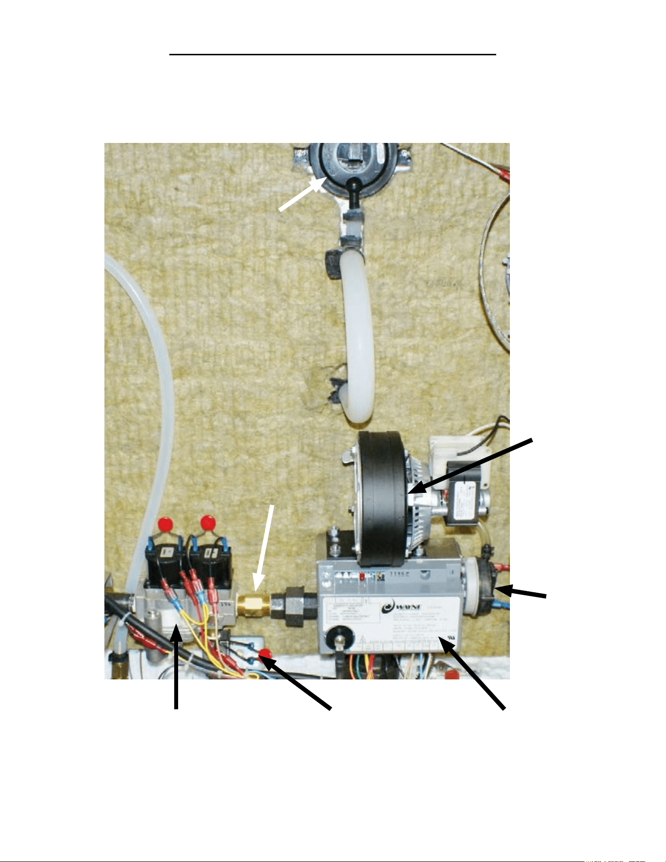
LOCATION OF GAS COMPONENTS
Power Burner
Blower
Gas Orice
Chamber Pressure
Switch
Ignition Module
Power Burner
Blower
Pressure
Switch
Gas Enrichment
Valve
Gas Control
Valve
SP8026-1201 Pg 21
GAS COMPONENTS REMOVAL & INSTALLATION
SP8026-1201 Pg 22
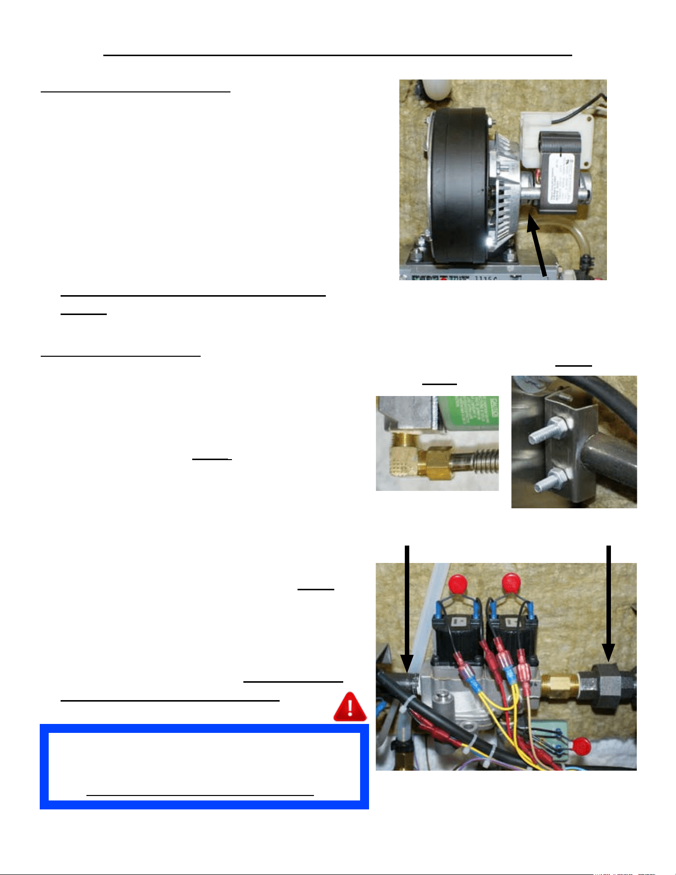
POWER BURNER BLOWER
Unplug the Unit & remove the Left-Side Panel 1.
by removing the Sheet Metal Screws holding it
in place.
Disconnect the Wiring Terminals from the Fan 2.
(note wire color location to the Fan’s wires).
Disconnect the Blower Pressure Switch Hose 3.
from the bottom of the Power Burner Blower.
Remove the 4 mounting nuts at Blower base.4.
Remove the Power Burner Blower.5.
Re-install in reverse order. 6.
Ensure the Blower’s Air Shutter is set as
follows: Natural = 3” & Propane = 3”
Fan Pressure Switch Hose
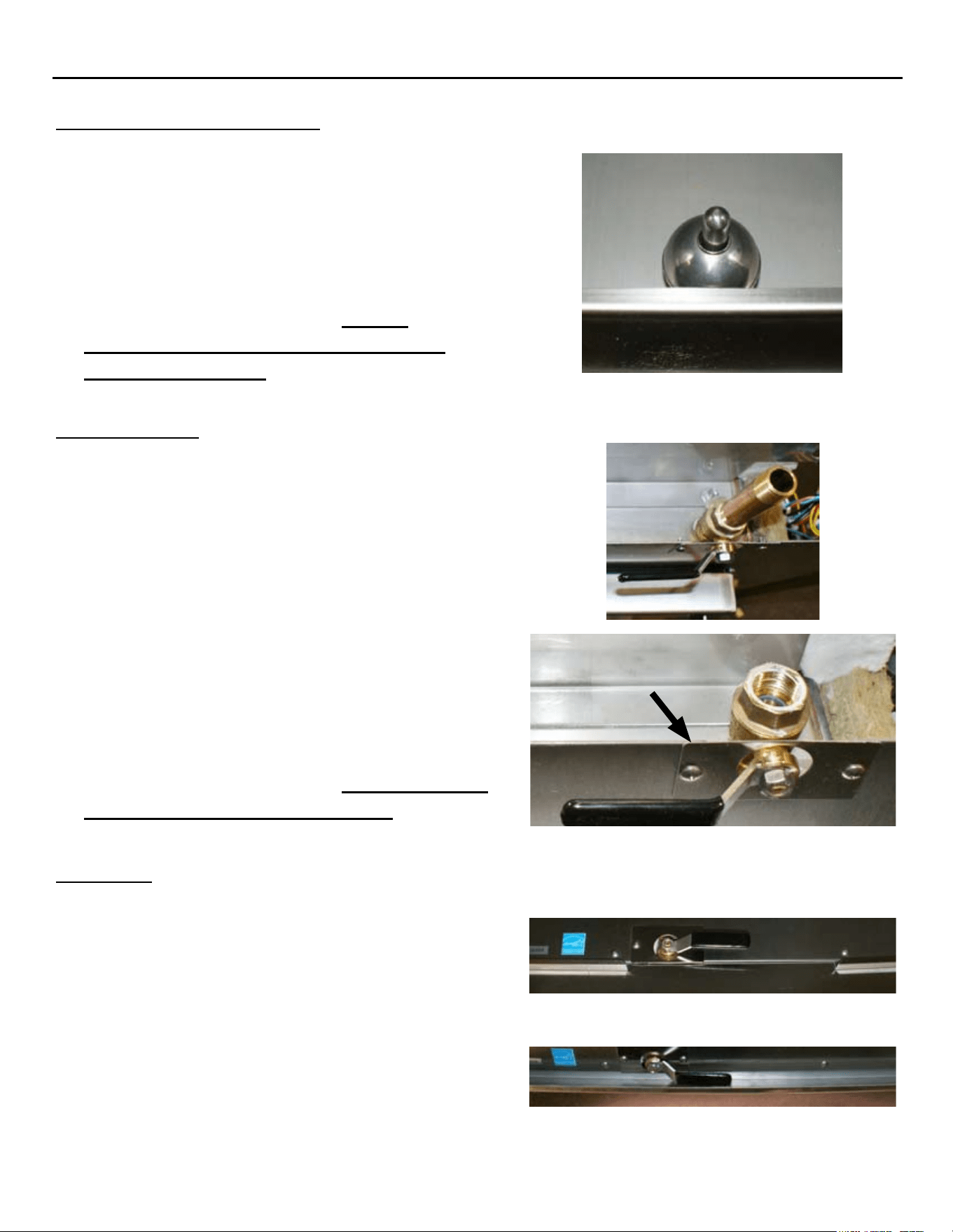
GAS CONTROL VALVE
Shut OFF the Supply Gas Valve & disconnect 1.
the Supply Gas Hose.
Unplug the Unit & remove the Left-Side Panel. 2.
Disconnect the Gas Line from the Enrichment 3.
Valve to the Burner. Fig A
Disconnect the Wiring Terminals from the Gas 4.
& Enrichment Valves (note wire color location
to each valve’s wires).
Disconnect the Union Coupler on the output 5.
(right-hand) side of the unit’s Gas Valve.
Loosen the Retaining Bracket of the Inlet Gas 6.
Pipe (left side of Gas Control Valve). Fig B
Disconnect the Gas Control Valve’s Inlet Gas 7.
Pipe.
Remove the Gas Orice & Gas Union Coupler.8.
Remove the Gas Enrichment Valve.9.
Re-install in reverse order. 10. Ensure Sealant
is re-applied to all pipe threading.
Fig B
Fig A
Union CouplerInlet Gas Pipe
After Replacing Gas Valves, it is Mandatory to Check
and Verify that the Gas Valve has the Proper Water
Column (WC) Value Measured with a Manometer.
Also Conrm No Gas Leaks Are Present.
GAS COMPONENTS REMOVAL & INSTALLATION
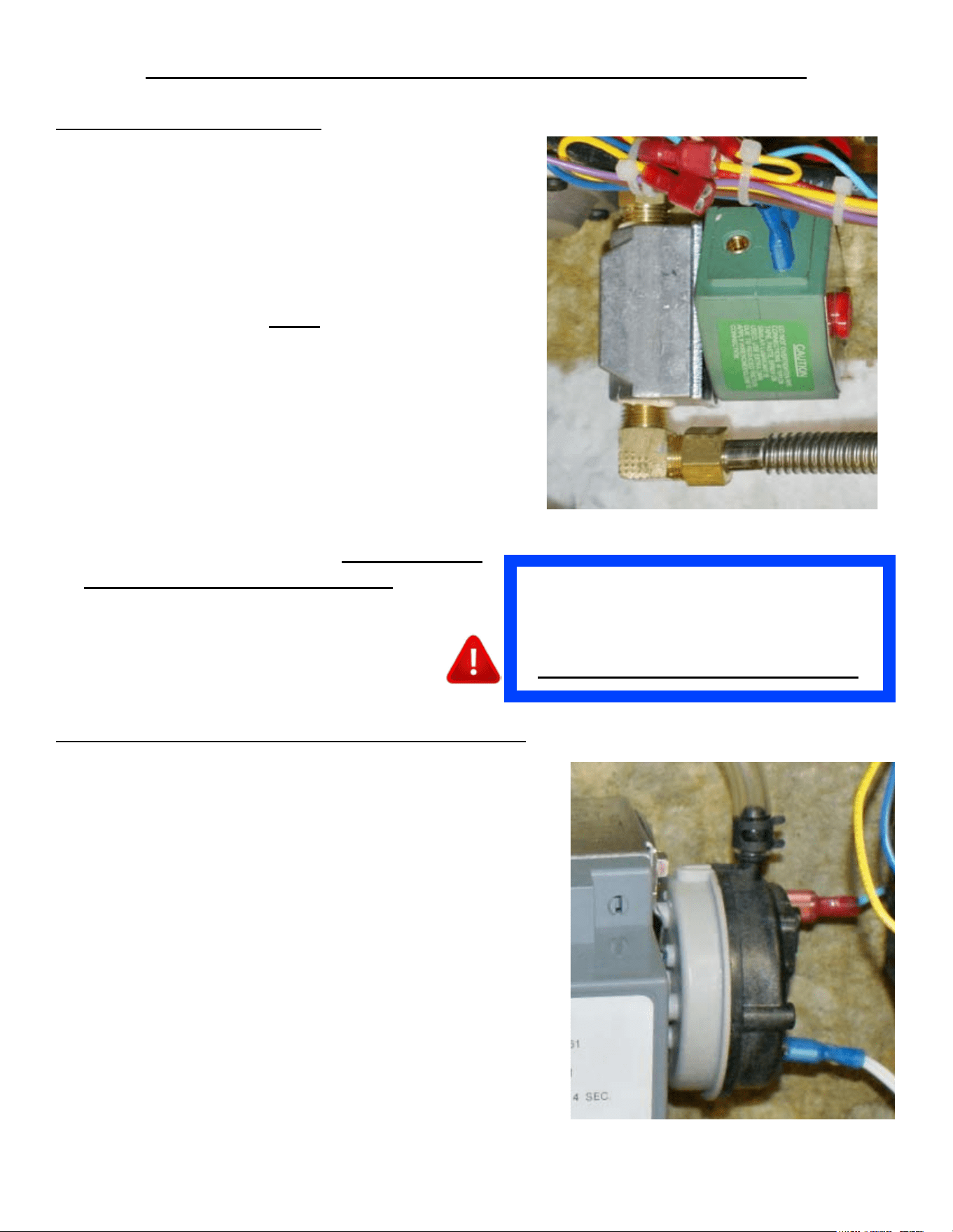
GAS ENRICHMENT VALVE
Shut OFF the Supply Gas Valve & disconnect 1.
the Supply Gas Hose.
Unplug the Unit & remove the Left-Side Panel 2.
by removing the Sheet Metal Screws holding it
in place.
Disconnect the Gas Line from the Enrichment 3.
Valve to the Burner. Fig A
Disconnect the Wiring Terminals from the 4.
Enrichment Valve (note wire color location to
the valve’s wires).
Disconnect and remove the Enrichment Valve 5.
from under the unit’s Gas Control Valve.
Remove the 906. ° elbow.
Remove the MOV Wires (7. note their location on
the Enrichment Valve).
Re-install in reverse order. 8. Ensure Sealant
is re-applied to all pipe threading.
SP8026-1201 Pg 23
POWER BURNER BLOWER PRESSURE SWITCH
Unplug the Unit & remove the Left-Side Panel 1.
by removing the Sheet Metal Screws holding it in
place.
Disconnect the Wiring Terminals from the Power 2.
Burner Blower Pressure Switch (note wire color
location to the switch’s wires).
Remove the hose clamp and disconnect the hose to 3.
the Power Burner Blower Pressure Switch.
Remove the 2 mounting screws on the Power 4.
Burner Blower Pressure Switch mounting bracket.
Remove the 3 screws holding the Power Burner 5.
Blower Pressure Switch to the mounting bracket.
Remove the Power Burner Blower Pressure Switch.6.
Re-install in reverse order.7.
After Replacing Gas Enrichment Valve, it is
Mandatory to Check and Verify that the
Gas Valve has the Proper Water Column
(WC) Value Measured with a Manometer.
Also Conrm No Gas Leaks Are Present.
GAS COMPONENTS REMOVAL & INSTALLATION
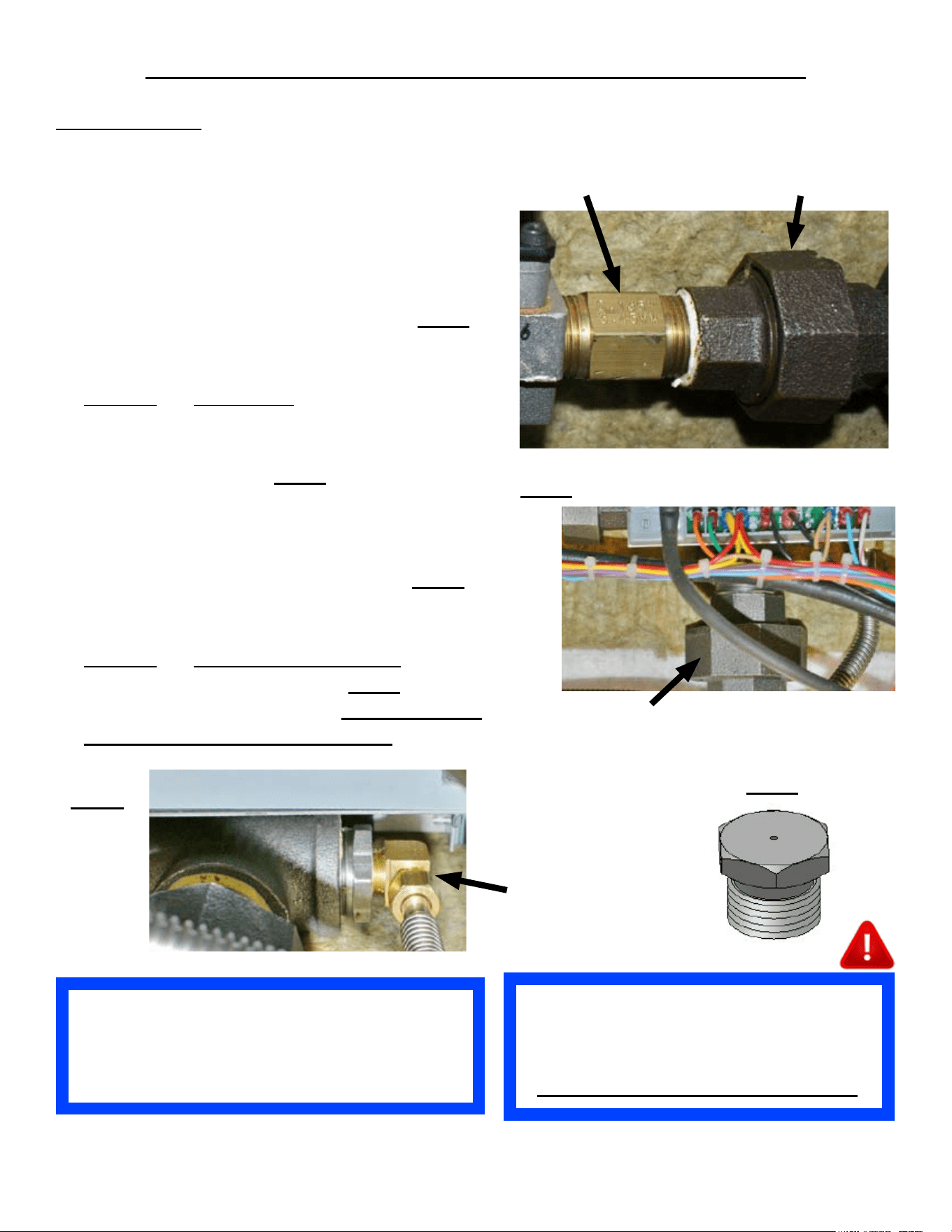
SP8026-1201 Pg 24
After Replacing Gas Orices, it is
Mandatory to Check and Verify that the
Gas Valve has the Proper Water Column
(WC) Value Measured with a Manometer.
Also Conrm No Gas Leaks Are Present.
USE THE GAS ORIFICE PER
ALTITUDE CHART, ON PAGE 40, TO
ENSURE THE PROPER ORIFICE
SIZES IS USED.
GAS ORIFICES
Shut OFF the Supply Gas Valve & disconnect 1.
the Supply Gas Hose.
Unplug the Unit & remove the Left-Side Panel.2.
Disconnect the Gas Union Coupler on the 3.
output (right) side of the Gas Control Valve.
Loosen the Retaining Bracket of the Inlet Gas 4.
Pipe (left side of Gas Control Valve). Fig B
Remove the Gas Union Coupler Fitting from 5.
the Gas Orice.
Remove6. the Gas Orice from the Gas Control
Valve.
Disconnect the Burner Union Coupler below 7.
the Ignition Module. Fig C
Pull-out the Ignition Module Bracket and 8.
angle it to allow access to the end of the Gas
Enrichment Valve Hose, attached to the piping
behind the Ignition Module Bracket. Fig D
Detach the Gas Enrichment Hose tting to 9.
allow access to the Gas Enrichment Orice.
Remove10. the Gas Enrichment Orice from the
Gas Enrichment Hose tting. Fig E
Re-install in reverse order. 11. Ensure Sealant
is re-applied to all pipe threading.
Union CouplerGas Orice
Fig C
Burner Union Coupler
Fig E
Fig D
Gas
Enrichment
Hose End
Fitting
LOCATION OF GAS BURNER & GAS BURNER BOX
Burner Gas
View Window
Ignition Probe Assembly Gas Power Burner Cover
Gas Power Burner
Union Elbow
Gas Burner Box
SP8026-1201 Pg 25
GAS POWER BURNER REMOVAL & INSTALLATION
GAS POWER BURNER
Shut OFF the Supply Gas Valve & disconnect 1.
the Supply Gas Hose & Unplug the unit.
Turn the unit upside-down and remove its legs. 2.
(Unbolt from stand and then turn unit upside-
down if applicable.)
Remove Left-Side Panel & Bottom Cover. 3.
(Remove Drain Pan Rails if applicable.)
Remove the Ignition Probe Sensor Bracket’s 4.
2 screws. (Note the orientation of the Ignition
Probe in ref to the Gas Burner Union Coupler.)
Remove the Insulation as needed to provide 5.
access to remove the Gas Burner from its Gas
Burner Box. (Note the insulation location for
proper tting when re-installed.)
Disconnect the Gas Burner Union Coupler.6.
Remove the 2 mounting screws from Gas 7.
Burner’s support bracket.
Remove the Gas Power Burner by sliding it out 8.
of the Gas Burner Box.
Re-install in reverse order.9.
Ignition Probe Bracket
Burner Union Coupler
Gas Burner Cover
After Replacing Gas Burner, it is Mandatory to Check
and Verify that the Gas Valve has the Proper Water
Column (WC) Value Measured with a Manometer.
Also Conrm No Gas Leaks Are Present.
SP8026-1201 Pg 26
GAS POWER BURNER BOX REMOVAL & INSTALLATION
GAS POWER BURNER BOX
Shut OFF the Supply Gas Valve & disconnect 1.
the Supply Gas Hose & Unplug the unit.
Turn the unit upside-down and remove its legs. 2.
(Unbolt from stand and then turn unit upside-
down if applicable.)
Remove Left-Side Panel & Bottom Cover by 3.
removing the Sheet Metal Screws holding it in
place. (Remove Drain Pan Rails if applicable.)
Fig F
Remove the Ignition Probe Sensor Bracket’s 4.
2 screws. (Note the orientation of the Ignition
Probe in ref to the Gas Burner Union Coupler.)
Remove the Insulation as needed to provide 5.
access to remove the Gas Burner Box. (Note
the insulation location for proper tting when
re-installed.) Fig G
Disconnect the Burner Union Coupler.6.
Remove the 2 mounting screws from Gas 7.
Burner’s support bracket.
Remove the Gas Burner by sliding it out of the 8.
Gas Burner Box.
Fig F
Fig G
Bottom Cross-BraceGas Burner Box Bottom
Front
Of
Steamer
Gas Burner
SP8026-1201 Pg 27
GAS POWER BURNER BOX REMOVAL & INSTALLATION
Flue Exit
Burner Box
Burner
Thermal
Gasket
Flue
Side
Points
To
The
Back
Of
The
Steamer
SP8026-1201 Pg 28
GAS POWER BURNER BOX (CON’T)
9. Unscrew the PWR Cord retaining tting on the
Back Panel and pull some slack through the
tting, to allow for some room to remove the
Back Panel.
10. Unscrew the Back Panel’s sheet metal screws
and remove the Back Panel.
11. Remove the 2 bottom structural cross-braces.
12. Remove the mounting nuts on the Flue and the
Burner Box.
13. Remove the Exhaust Flue off the Gas Burner
Box. Fig H
14. Lift and remove the Burner Box. (Might have
to use a at-head screwdriver to pry up the Gas
Burner Box from the Gas Burner Gasket.)
15. Re-install in reverse order.
Fig H
Prior to installing the new Burner Box:
Scrap, remove, and clean-off any •
remaining Gas Burner Gasket residue
from the steamer’s bottom (where the
mounting studs are located).
Apply the 3 new Gas Burner Gaskets •
to the Bottom of the Gas Burner Box.
Side Gaskets = AT1I-3771-4 (Need 2)
Front Gasket = AT1I-37771-3
After Replacing Burner Box, it is Mandatory to Check
and Verify that the Gas Valve has the Proper Water
Column (WC) Value Measured with a Manometer.
Also Conrm No Gas Leaks Are Present.
LOCATION OF HEAT TRANSFER PLATE
The Zinc Flat Washer, Lock Washer, and 1/4-20# Nut Can Only Be Used Once.
Ensure That New Zinc Hardware is Ordered (Minimum of 24 Each Required) and
Received; Prior to Removing or Installing the Heater Transfer Plate.
Zinc 1/4-20# Nut = AT0F-2778-51002
Zinc 1/4” Flat Washer = AT0F-1052-51002
Zinc 1/4” Lock Washer = AT0F-2666-51002
NOTE
Ensure That Thermal Joint Compound is Ordered (Minimum Of 2 Required) and
Received, Prior to Removing or Installing the Heater Transfer Plate.
Thermal Joint Compound = AT0H-3412-2
NOTE
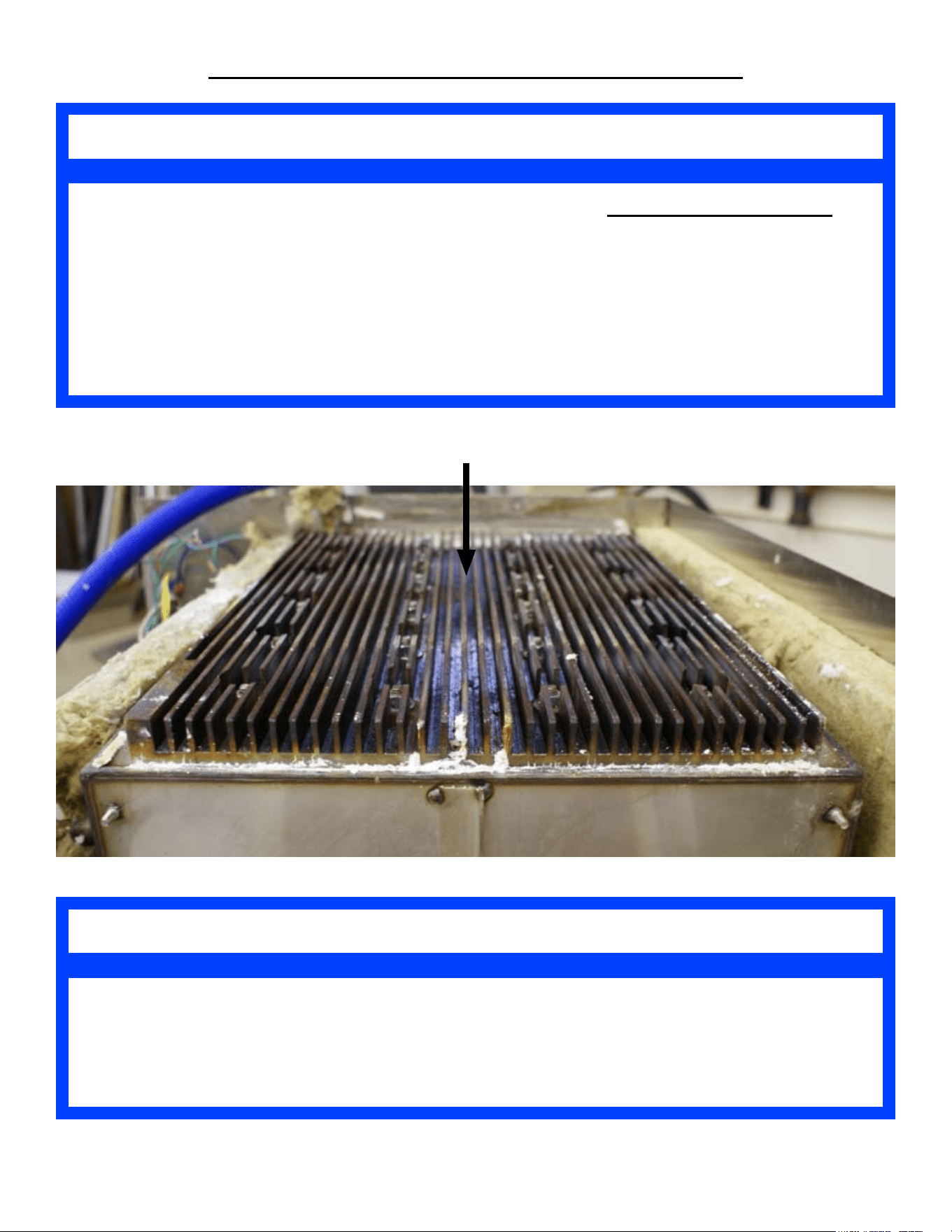
Heat Transfer Plate
SP8026-1201 Pg 29
HEAT TRANSFER PLATE REMOVAL & INSTALLATION
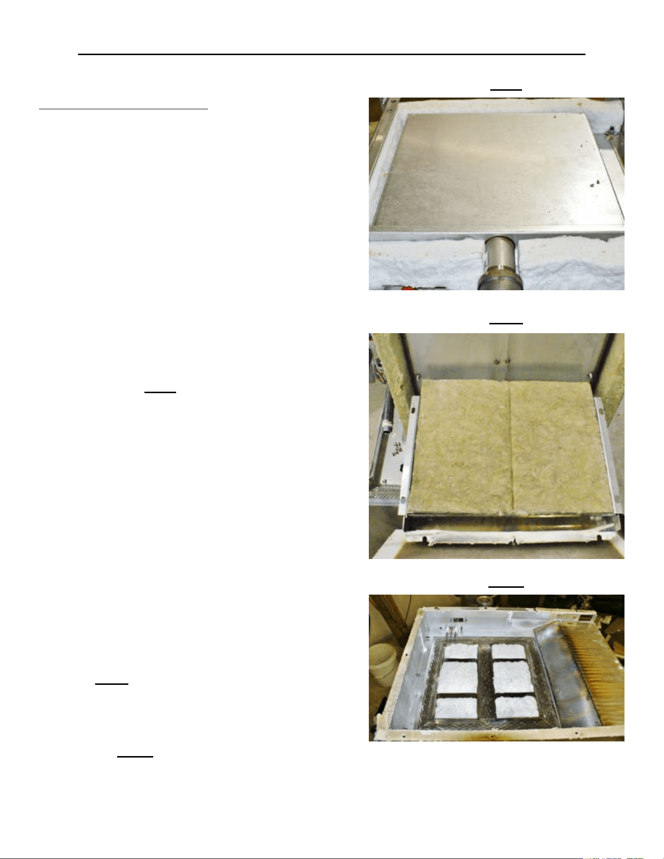
HEAT TRANSFER PLATE
Shut OFF the Supply Gas Valve & disconnect 1.
the Supply Gas Hose & Unplug the unit.
Turn the unit upside-down and remove its legs. 2.
(Unbolt from stand and then turn unit upside-
down if applicable.)
Remove Left-Side Panel & Bottom Cover by 3.
removing the Sheet Metal Screws holding it in
place. (Remove Drain Pan Rails if applicable.)
Remove the Ignition Probe Sensor Bracket’s 4.
2 screws. (Note the orientation of the Ignition
Probe in ref to the Gas Burner Union Coupler.)
Remove the Insulation as needed to provide 5.
access to remove the Gas Burner Box. (Note
the insulation location for proper tting when
re-installed.) Fig I
Disconnect the Burner Union Coupler.6.
Remove the 2 mounting screws from Gas 7.
Burner’s support bracket.
Remove the Gas Burner by sliding it out of the 8.
Gas Burner Box.
9. Unscrew the PWR Cord retaining tting on the
Back Panel and pull some slack through the
tting, to allow for some room to remove the
Back Panel.
10. Unscrew the Back Panel’s sheet metal screws
and remove the Back Panel.
11. Remove the 2 bottom structural cross-braces.
12. Remove the mounting nuts on the Flue and the
Burner Box.
13. Remove the Exhaust Flue off the Gas Burner
Box. Fig J
14. Lift and remove the Gas Burner Box. (Might
have to use a at-head screwdriver to pry
up the Gas Burner Box from the Gas Burner
Gasket.) Fig K
Fig I
Fig J
Fig K
SP8026-1201 Pg 30
HEAT TRANSFER PLATE REMOVAL & INSTALLATION
If Heater Studs are Discovered Broken While Removing the Heater Transfer Plate
OR
If a Heater Stud Breaks-Off While Removing or Installing the Heater Transfer Plate
Call AccuTemp Service Dept (800) 480-0415.
NOTE
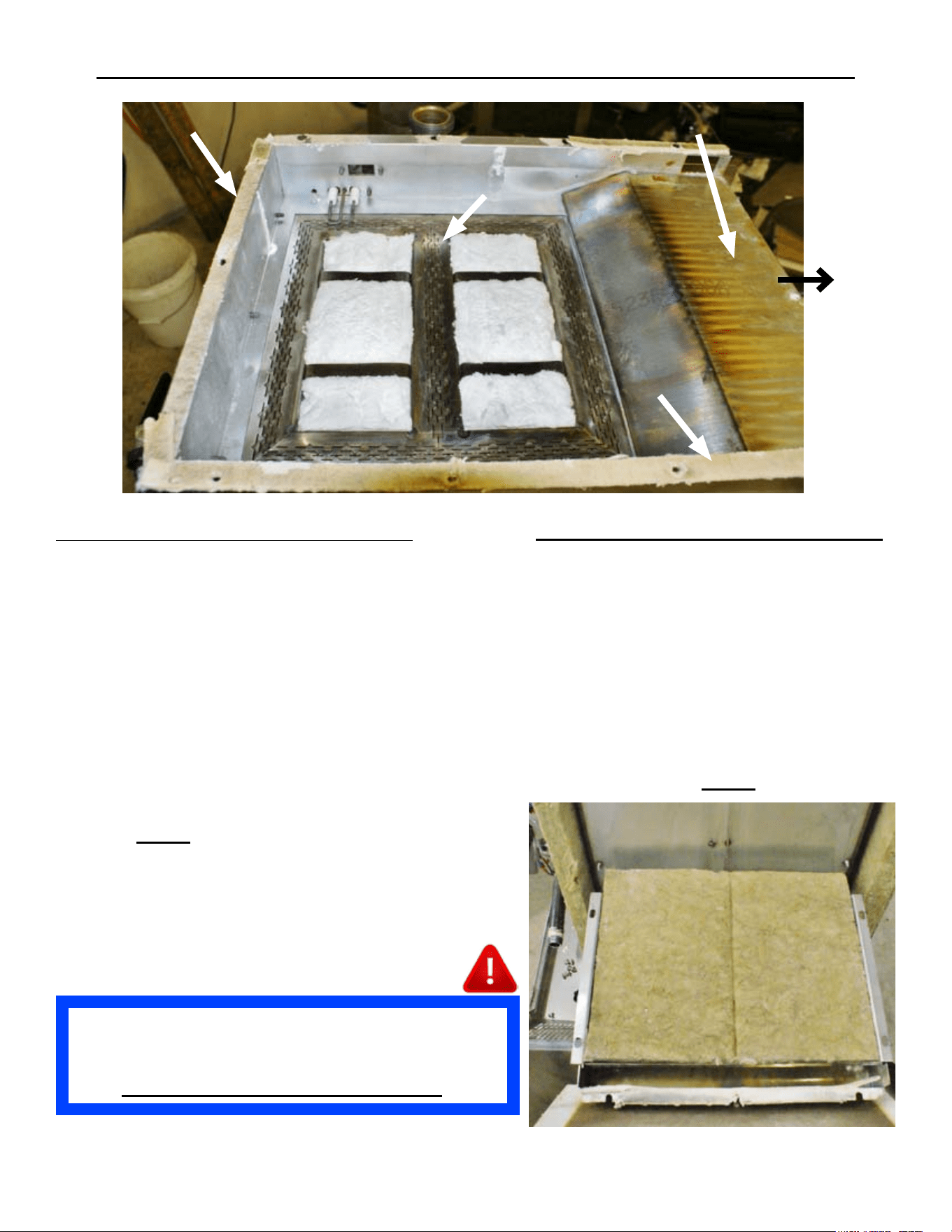
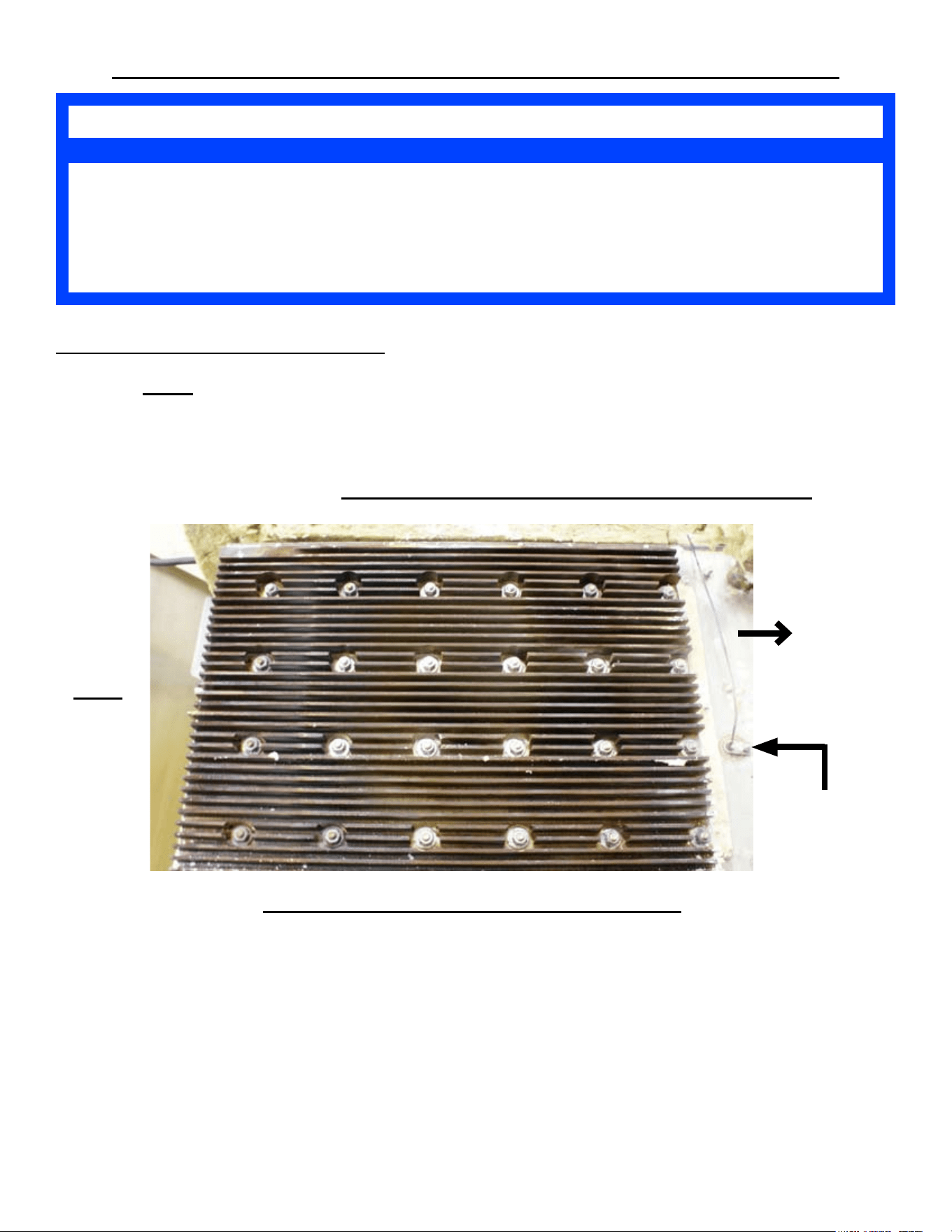
HEAT TRANSFER PLATE (CON’T)
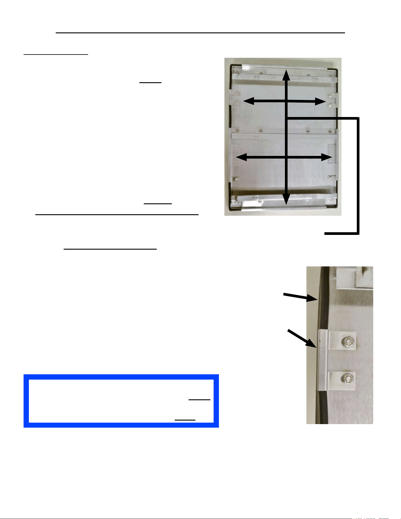
15. Using Fig L, Loosen all 24 nuts by starting with Zinc Nut #24 and working down to #1.
16. Remove all 24, Zinc Nut, Lock & Flat Washers from the Heat Transfer Plate.
17. Remove the Heat Transfer Plate. (Might have to use a at-head screwdriver to pry up the
Heater Plate from the Thermal Compound.)
18. Re-install in reverse order. SEE NEXT PAGE FOR INSTALLATION NOTES.
Prior to installing the new Heat Transfer Plate:
Scrap, remove, and clean-off any remaining Thermal Compound residue from the steamer’s •
bottom (where the mounting studs are).
Apply Thermal Compound with a Square “D” notch trowel to the new Heat Transfer Plate’s •
at surface that makes contact with the steam chamber bottom.
Scrap, remove, and clean off any remaining Gas Burner Gasket residue from the steamer’s •
bottom (where the mounting studs are located).
Apply the 3 new Gas Burner Gaskets to the Bottom of the Burner Box when re-installing it. •
Side Gaskets = AT1I-3771-4 (Need 2) & Front Gasket = AT1I-37771-3
18
22
24
6
14
16
7
11
4
2
10
12
3
1
9
5
17
13
21
15
23
8
20
19
Front
Side
Of
The
Steamer
Fig L
Reed Switch
Probe or
Probe Hole
SP8026-1201 Pg 31
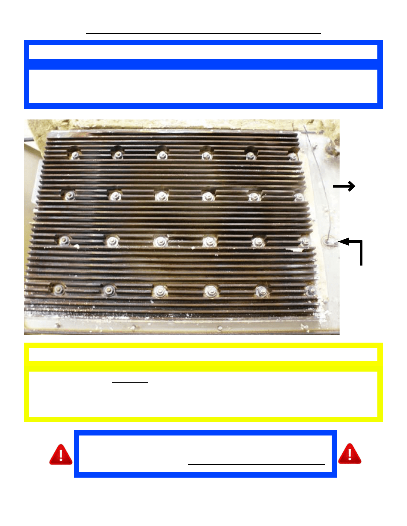
HEAT TRANSFER PLATE INSTALLATION
DO NOT OVER TORQUE THE ZINC NUTS.
Over Torquing The Zinc Nuts Can Cause the Studs to Break-Off. This Will Cause
Heating Issues; and the Steamer Will Not Operate Correctly or Safely.
CAUTION
The Zinc HEX Nut Needs to be Torqued Between 34 & 40 IN-LBS. Tighten Starting
with Zinc Nut #1 and Follow the Numbered Layout Pattern to Nut #24.
Tighten Twice in This Pattern.
NOTE
4
3
1
2
5
6
7
8
9
11
10
12
13
15
14
16
19
24
22
18
17
21
23
20
Front
Side
Of
The
Steamer
Reed
Switch
Probe
or
Probe
Hole
After Replacing Heat Transfer Plate, it is Mandatory to Check and
Verify that the Gas Valve has the Proper Water Column (WC) Value
Measured with a Manometer. Also Conrm No Gas Leaks Are Present.
SP8026-1201 Pg 32
MISCELLANEOUS COMPONENTS REMOVAL & INSTALLATION
SP8026-1201 Pg 33
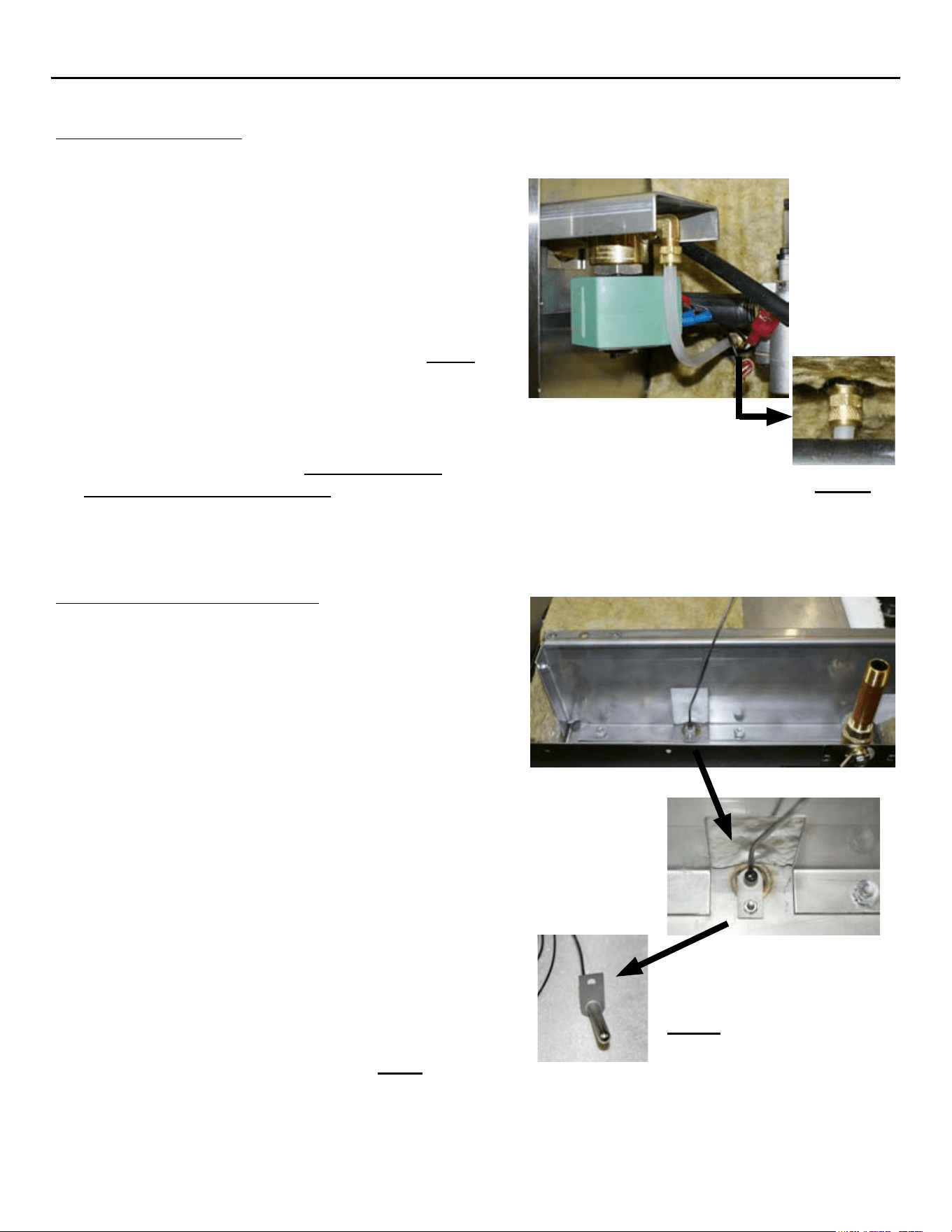
AUTO-FILL VALVE
Unplug the Unit & drain any remaining water from the 1.
steam chamber.
Close the supply water valve and disconnect the Supply 2.
Water Hose coming into the steamer.
Remove the Left-Side Panel by removing the Sheet 3.
Metal Screws holding it in place.
Disconnect the wires from the Auto-Fill Valve (4. note the
wire color to its location pin).
Disconnect the Auto-Fill Valve Hose Fitting. 5. Fig M
On the back of the steamer, remove the 4 mounting 6.
screws securing the Auto-Fill Valve bracket on the
inside of the steamer.
Remove the Auto-Fill Valve.7.
Re-install in reverse order. 8. Ensure Sealant is
re-applied to all pipe threading.
Fig M
OVER-FILL REED SWITCH
Unplug Unit & close the supply water valve.1.
Disconnect the garden hose from the back of the 2.
steamer & drain any remaining water from the steam
chamber.
Remove the Left-Side Panel by removing the Sheet 3.
Metal Screws holding it in place.
Disconnect the REED Switch wires (4. note the wire
color to its location pin).
Turn the unit upside-down and remove its legs. 5.
(Unbolt from stand and then turn unit upside-down if
applicable.)
Remove Bottom Cover by removing the Sheet Metal 6.
Screws holding it in place. (Remove Drain Pan Rails
if applicable.)
Remove the front, insulation pieces that are laying 7.
on-top of the Over-Fill Reed Switch. (Wire is ran
in-between the insulation pieces.)
Remove the retaining nut and lock washer holding the 8.
Reed Switch inside the Sensor Post.
Remove the High Water Reed Switch. 9. Fig N
Re-install in reverse order.10.
Fig N
MISCELLANEOUS COMPONENTS REMOVAL & INSTALLATION
DRAIN VALVE
Unplug the Unit & drain any remaining water 1.
from the steam chamber.
Turn the unit upside-down and remove its 2.
legs. (Unbolt from stand and then turn unit
upside-down if applicable.)
Remove Bottom Cover by removing the Sheet 3.
Metal Screws holding it in place. (Remove
Drain Pan Rails if applicable.)
Remove the Drain Handle Cover Plate, and the 4.
insulation surrounding the Drain Valve.
Remove the Drain Pipe from the Drain Valve.5.
Remove the Drain Valve.6.
Re-install in reverse order. 7. Ensure Sealant
is re-applied to all pipe threading.
Drain Cover
Plate
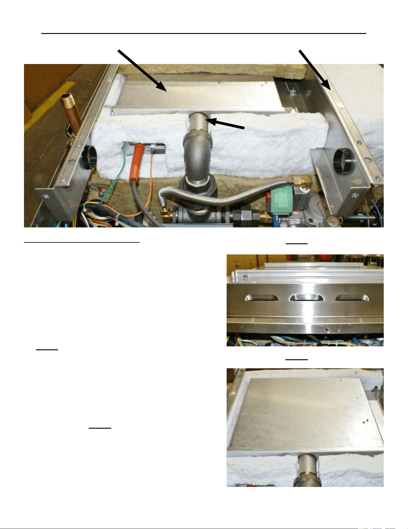
DRIP PAN
Unplug the Unit.1.
Remove the 4 Sheet Metal Screws at the 2.
bottom of the Front Panel.
Slide the Drip Pan(s) out from between the 3.
Front Panel and the Bottom Panel. (Ensure the
split Drip Pans are sloped towards the center
of the steamer.)
Re-install in reverse order.4.
Split Drip Pan
Solid Drip Pan
FLOAT BALL (MAGNETIC)
Open the steamer Door and remove the left-1.
side pan rail.
Lift and remove the steam collection cover 2.
plate.
Remove the Float Ball off of the High Water 3.
Reed Switch Sensor Post.
Re-install in reverse order. 4. Ensure
Sensor Post & Float Ball hole are clean
before re-installing.
SP8026-1201 Pg 34
DOOR COMPONENTS REMOVAL & INSTALLATION
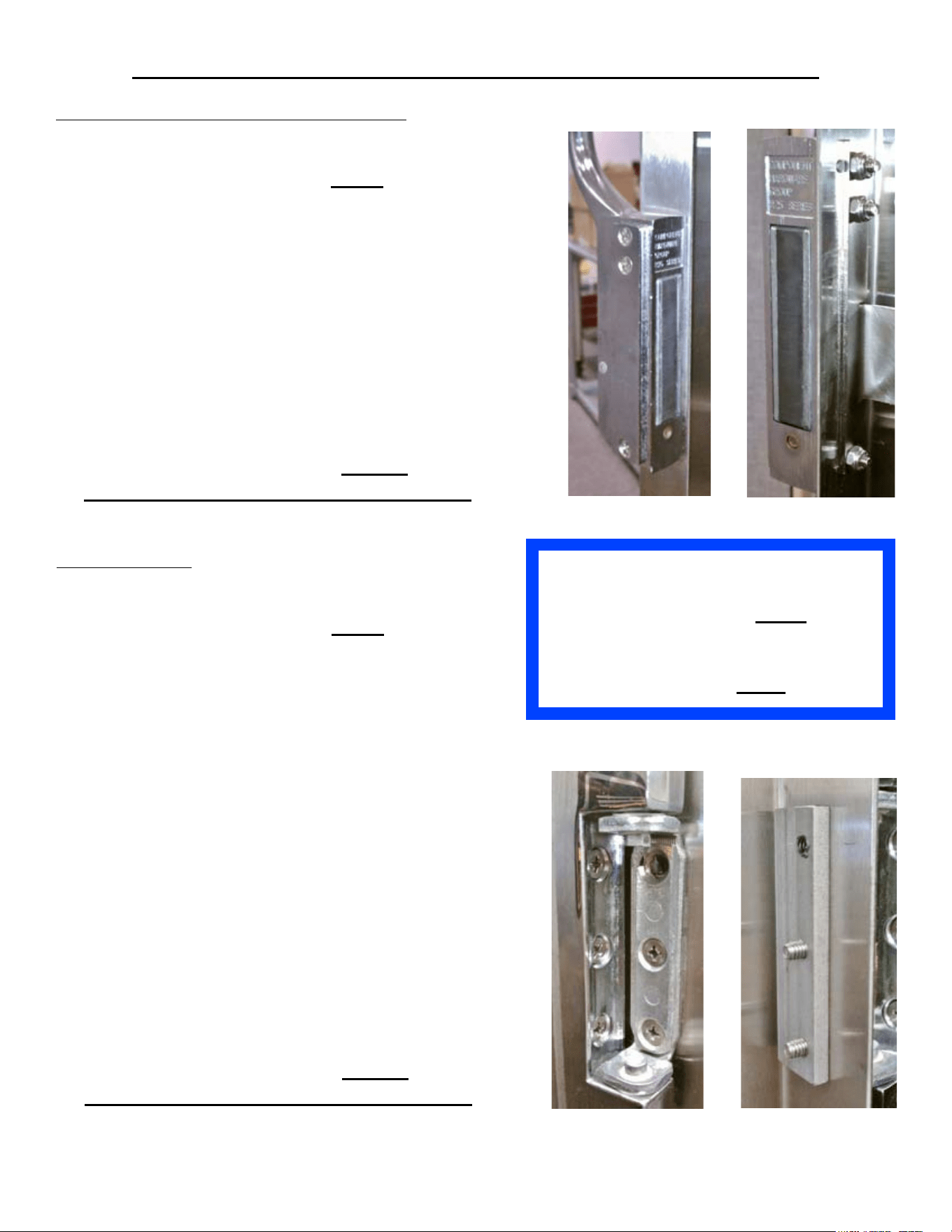
If the Door Handle Latch Is Moved to the Opposite
Side, Ensure That the Door Switch Is Moved to the
Corresponding Door Handle Latch Side .
STEAMER WILL NOT OPERATE IF NOT DONE.
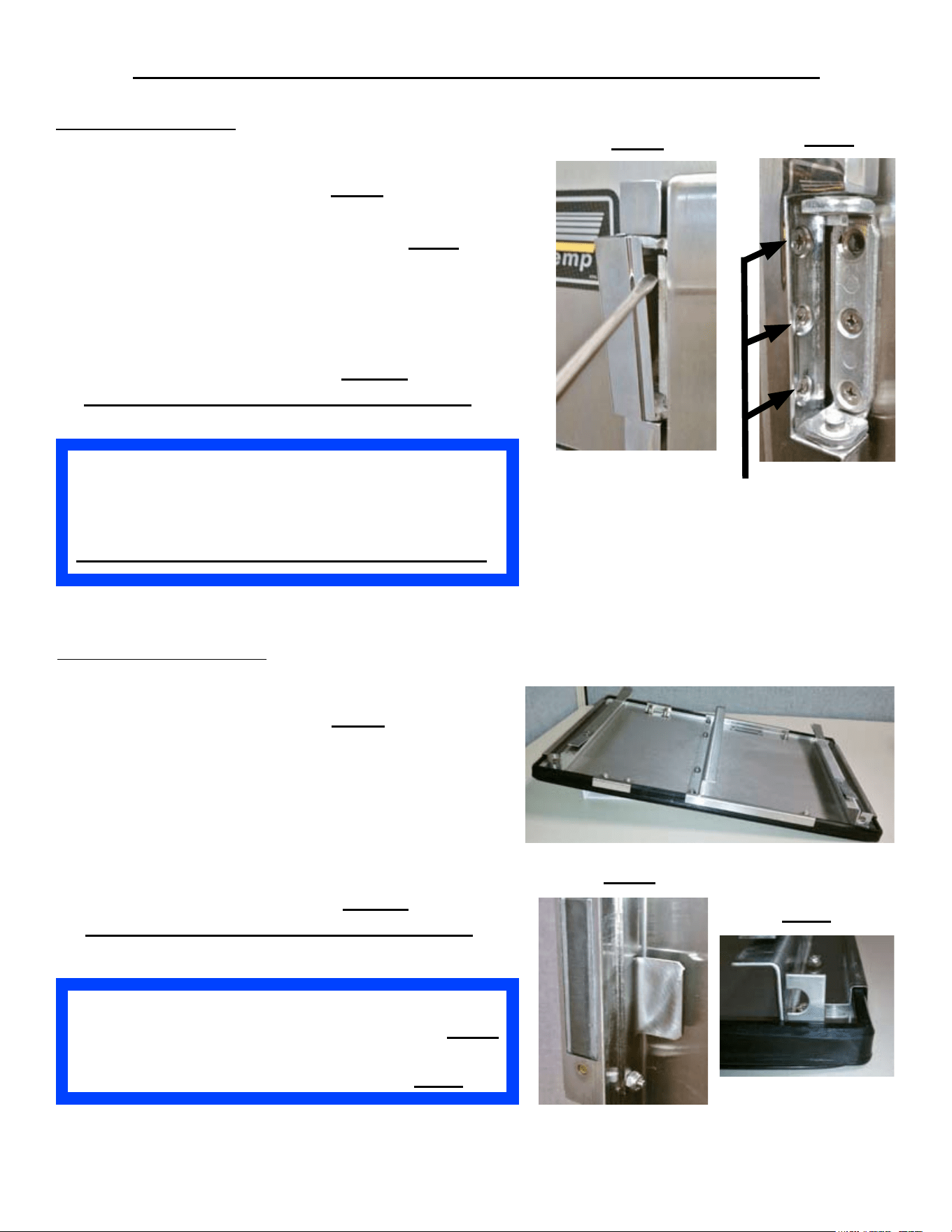
DOOR ASSEMBLY
Unplug the unit and shut the Door.1.
Remove the Hinge Covers. 2. Fig O
Remove the 3 hinge screws going into the face 3.
of the steamer of the Bottom Hinge. Fig P
While supporting the Door on the hinge-side, 4.
remove the 3 hinge screws into the face of the
steamer of the Top Hinge.
Pull the door handle and remove the Door.5.
Re-install in reverse order. 6. Ensure
Anti-sieze is re-applied to all hinge screws.
Fig O
Fig P
Face Screws
Ensure That the Inner Door is Reinstalled with its
Middle Brace Bar Behind the Door Latch Tab. Fig R
Also, Ensure That the Screw Retainer Openings are
Lined-Up with the Door’s Hinge Side. Fig S
Fig S
Fig R
INNER-DOOR PANEL
Unplug the unit and shut the Door.1.
Remove the Hinge Covers. 2. Fig O
Remove the very bottom screw on the door 3.
hinge-side of the Bottom Hinge.
Remove the very top screw on the door 4.
hinge-side of the Top Hinge.
Pull the door handle and open the door5.
Lift and pull out the Inner Door Panel.6.
Re-install in reverse order. 7. Ensure
Anti-sieze is re-applied to all hinge screws.
Inner Door
SP8026-1201 Pg 35
DOOR COMPONENTS REMOVAL & INSTALLATION
Ensure That the Inner Door is Reinstalled
with its Middle Brace Bar Behind the
Door Latch Tab. Fig R
Also, Ensure That the Screw Retainer
Openings are Lined-Up with the Door’s
Hinge Side. Fig S
DOOR HANDLE LATCH ASSEMBLY
Unplug the unit & shut the Door.1.
Remove the Hinge Covers. 2. Fig O
Remove the very bottom screw on the door 3.
hinge-side of the Bottom Hinge & remove the
very top screw on the door-side hinge of the
Top Hinge.
Pull the door handle and open the door4.
Lift and pull out the Inner Door Panel.5.
Remove the 3 mounting nuts and screws, 6.
holding the Door Handle Latch to the side of
the door, and the Inner Door Holding Tab.
Remove the Door Handle Latch Assembly.7.
Re-install in reverse order. 8. Ensure
Anti-sieze is re-applied to all hinge screws.
DOOR HINGE
Unplug the unit & shut the Door.1.
Remove the Hinge Covers. 2. Fig O
Remove the 3 hinge screws going into the face 3.
of the steamer of the Bottom Hinge.
While supporting the Door on the hinge-side, 4.
remove the 3 hinge screws into the face of the
steamer of the Top Hinge.
Pull the door handle and remove the Door.5.
Remove the very bottom screw on the door 6.
hinge-side of the Bottom Hinge & remove the
very top screw on the door-side hinge of the
Top Hinge.
Lift and pull out the Inner Door Panel.7.
Remove the remaining door-side screws for 8.
the hinge or hinges to be replaced. (Note the
orientation of the Hinge Spacer Bars as they
relate to the Hinge orientation.)
Remove the Door Hinge or Hinges.9.
Re-install in reverse order. 10. Ensure
Anti-sieze is re-applied to all hinge screws.
SP8026-1201 Pg 36
DOOR COMPONENTS REMOVAL & INSTALLATION
DOOR GASKET
Unplug the unit & shut the Door.1.
Remove the Hinge Covers. 2. Fig O
Remove the very bottom screw on the door 3.
hinge-side of the Bottom Hinge & remove the
very top screw on the door-side hinge of the
Top Hinge.
Pull the door handle and open the door4.
Lift and pull out the Inner Door Panel.5.
Remove the 6, Gasket retaining brackets by 6.
removing the 12 nyloc mounting nuts holding
them in place.
Remove the Door Gasket.7.
Re-install in reverse order. 8. Ensure
Anti-sieze is re-applied to all hinge screws.
Gasket Retaining
Brackets
INSTALLATION NOTE:
Make sure the new Door Gasket is •
untangled.
Starting at one corner, stretch the Gasket •
to the opposite corner.
Repeat this sequence until all 4 corners •
are seated.
Push the Gasket down all the way around •
to ensure the Gasket seats rmly on the
inner door.
Ensure That the Inner Door is Reinstalled with its
Middle Brace Bar Behind the Door Latch Tab. Fig R
Also, Ensure That the Screw Retainer Openings are
Lined-Up with the Door’s Hinge Side. Fig S
Gasket
Gasket Retaining
Bracket
SP8026-1201 Pg 37
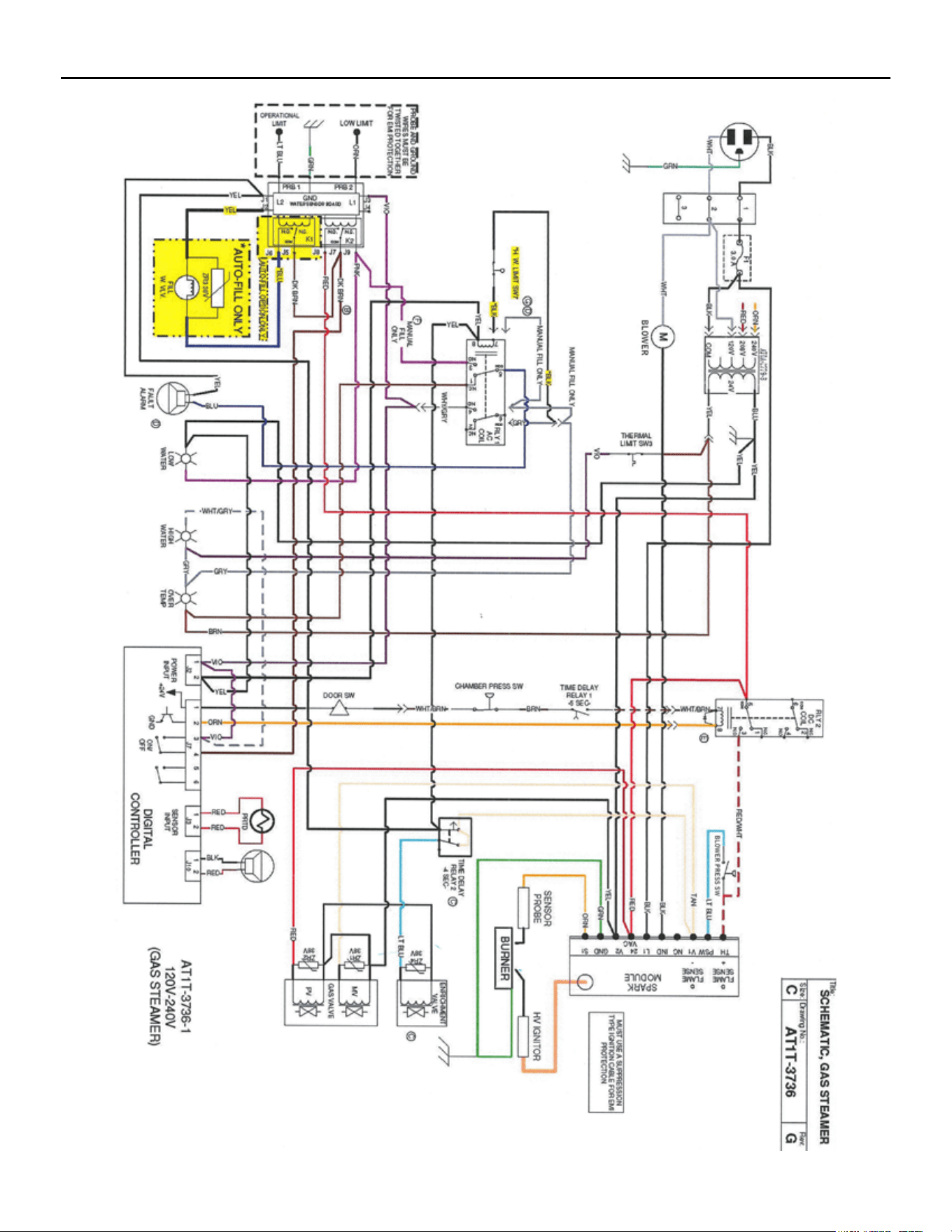
GAS EVOLUTION WIRING SCHEMATIC (S/N: 36980 & BELOW)
SP8026-1201 Pg 38
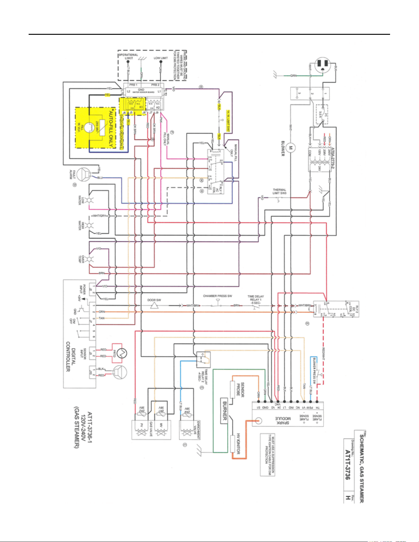
GAS EVOLUTION WIRING SCHEMATIC (S/N: 36981 & ABOVE)
SP8026-1201 Pg 39
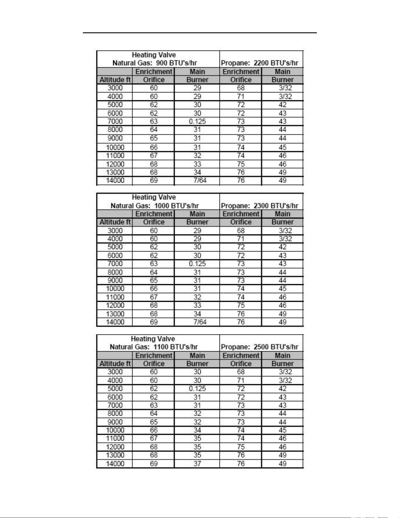
SP8026-1201 Pg 40
GAS ORIFICE SIZE TO ALTITUDE CHART
SP8026-1201 Pg 41
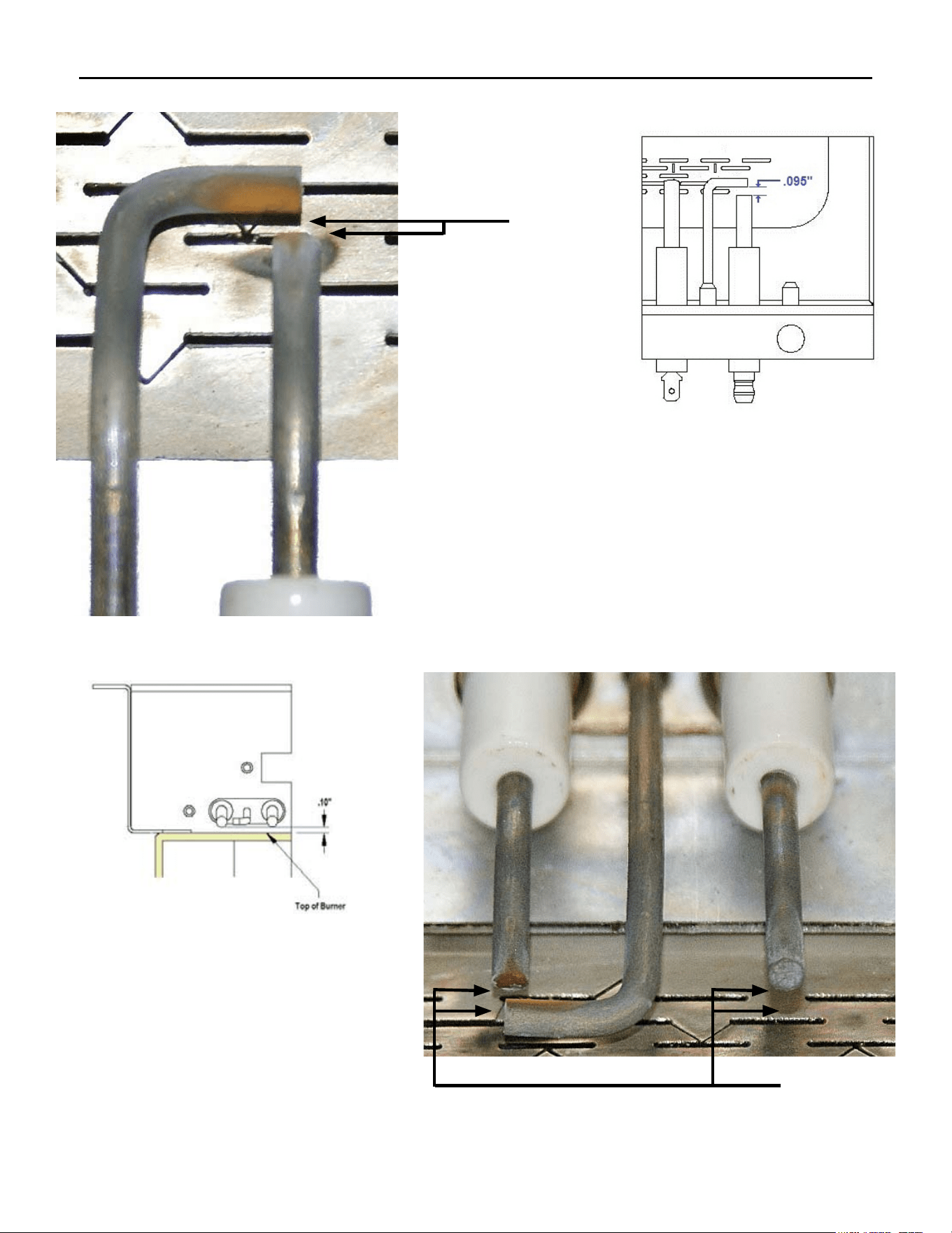
IGNITOR/FLAME SENSE PROBE SPACING MEASUREMENT
.095”
The distance between the GND Probe and the
Ignitor Probe is .095”. (This distance is roughly
the thickness size of a nickel.)
The distance between the Flame Sense
Probe/Ignitor Probe and the Burner’s
surface is .10”. (This distance is
roughly the thickness size of a nickel.)
.10”