PWR System Operator's Manual 1
OPERATING INSTRUCTIONS FOR
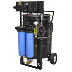
PORTABLE RECOVERY SYSTEM
PWR-10-0ME1
(AFTER SERIAL #30008283)
©Copyright 2011, Mi-T-M Corporation
®
Form #37-1160-E/F/S-050123
CAUTION
RISK OF INJURY!
READ MANUAL BEFORE OPERATING!
This manual is an important part of the PWR System and must
remain with the unit when you sell or rent it!

2 PWR System Operator's Manual
CONTENTS
INTRODUCTION .....................................................................................................................................................3
SAFETY WARNINGS .............................................................................................................................................. 5
PORTABLE WATER RECOVERY UNITS .............................................................................................................6
FEATURES LISTING ..............................................................................................................................................6
INSTALLATION & PREPARATION........................................................................................................................7
ATTIRE: .................................................................................................................................................................7
SET-UP: .................................................................................................................................................................7
POWER CORD CONNECTION: ..........................................................................................................................8
OPERATING INSTRUCTIONS ............................................................................................................................... 9
OPERATION: ........................................................................................................................................................9
SHUTDOWN: ........................................................................................................................................................9
STORAGE & MAINTENANCE .............................................................................................................................10
TROUBLESHOOTING .......................................................................................................................................... 11
SPECIFICATIONS ................................................................................................................................................. 12
PWR-10-0ME1 (AFTER SERIAL #30008283) ...................................................................................................... 14
CONTROL BOX ASSEMBLY (AFTER SERIAL #30007594) .............................................................................16
WX-0106 WHEEL KIT OPTION ............................................................................................................................ 18
WX-0109 DUAL FILTER OPTION (AFTER SERIAL #30008169) ......................................................................20
WIRING DIAGRAM (BEFORE SERIAL #3007594) ............................................................................................22
LADDER DIAGRAM (BEFORE SERIAL #3007594) ...........................................................................................23
WIRING DIAGRAM (AFTER SERIAL #30007594) .............................................................................................24
LADDER DIAGRAM (AFTER SERIAL #30007594) ............................................................................................ 25
STATEMENT OF WARRANTY .............................................................................................................................26
WARNING: This product can expose you to
chemicals including carbon monoxide, which is
known to the State of California to cause birth
defects or other reproductive harm. For more
information go to www.P65Warnings.ca.gov
WARNING
WARNING: This product can expose you to
chemicals including Lead, which is known to
the State of California to cause cancer and birth
defects or other reproductive harm. For more
information go to www.P65Warnings.ca.gov
WARNING
PWR System Operator's Manual 3
INTRODUCTION
Congratulations on the purchase of your new Portable Water Recovery System (PWR)! You can be assured your Mi-
T-M PWR was constructed and designed with quality and performance in mind. Each component has been rigorously
tested to ensure the highest level of acceptance.
This operator's manual was compiled for your benet. By reading and following the simple safety, installation, operation,
maintenance and troubleshooting steps described in this manual, you will receive years of trouble free operation from
your new PWR System. The contents of this manual are based on the latest product information available at the time
of publication. The manufacturer reserves the right to make changes in price, color, materials, equipment, specications
or models at any time without notice.
! IMPORTANT !
The following "Signal Words" are used throughout this manual to designate the degree or
level of hazard seriousness.
DANGER: Indicates an imminently hazardous situation which, if not avoided,
WILL result in death or serious injury.
WARNING: Indicates a potentially hazardous situation which, if not avoided,
COULD result in death or serious injury.
CAUTION: Indicates a potentially hazardous situation which, if not avoided
MAY result in minor or moderate injury.
The symbol set to the left of this paragraph is a "Safety Alert Symbol". This symbol is used
to call attention to items or procedures that could be dangerous to you or other persons
using this equipment.
ALWAYS PROVIDE A COPY OF THIS MANUAL TO ANYONE USING THIS EQUIPMENT. READ
ALL INSTRUCTIONS BEFORE OPERATING THIS PWR SYSTEM VAC AND ESPECIALLY POINT
OUT THE "SAFETY WARNINGS" TO PREVENT THE POSSIBILITY OF PERSONAL INJURY TO
THE OPERATOR.
Once the unit has been removed from the box, immediately write in the serial number of your unit in the space provided
below.
SERIAL NUMBER_________________________________
Inspect for signs of obvious or concealed freight damage. If damage does exist, le a claim with the transportation
company immediately. Be sure that all damaged parts are replaced an that the mechanical and electrical problems are
corrected prior to operation of the unit. If you require service, contact your Customer Service.
CUSTOMER SERVICE
CALL OUR TOLL-FREE NUMBER
for the Sales or Service Center nearest you!
800-553-9053
Please have the following information available for all service calls:
1. Model Number
2. Serial Number
3. Date and Place of Purchase
4 PWR System Operator's Manual
SAFETY WARNINGS
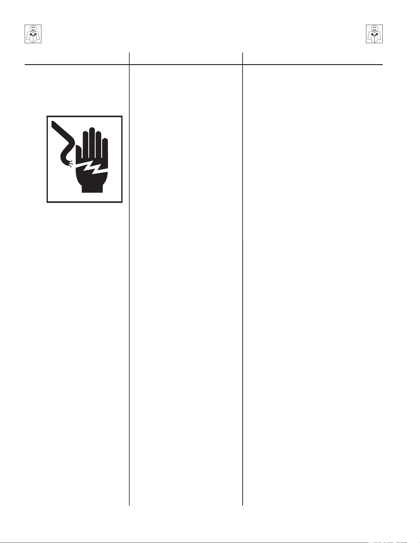
WARNING: When using this product, basic precautions should always be observed, including the following:
READ ALL SAFETY INSTRUCTIONS BEFORE USING PWR System
POTENTIAL CONSEQUENCE
PREVENTION
Serious injury or death could occur
if the PWR System is not properly
grounded. Your PWR System is
powered by electricity and may
cause electric shock or electrocution
if not used properly.
This product must be grounded. Connect to a
properly grounded outlet only. See "Grounding
Instructions".
Always be certain the unit is receiving proper
voltage. Before plugging the unit into a
compatible power source, be certain the switch
is in the "OFF" position. Disconnect when not
in use.
Do not modify plug provided with the product.
If it will not t the outlet, have a proper outlet
installed by a qualied electrician. Do not remove
the plug or use any type of adapter.
Do not expose the PWR System to rain or
submerge in water. Do not use pressurized
water to clean the PWR System. Store indoors.
Check power cord for signs of crushing, cutting
or heat damage. If replacement of plug or cord
is needed, use only identical replacement parts.
If PWR System is not working correctly, has
been dropped, damaged, left outdoors, or
dropped into water, return it to a service center.
Keep all connections dry and o the ground.
Do not allow electrical cords to lay in water or
in such a position where water could come in
contact with them. Do not handle plug or PWR
System with wet hands.
Do not pull or carry the unit by the electrical
cord. Do not use the cord as a handle, close a
door on cord, or pull cord around sharp edges
or corners. Do not run PWR System over cord.
Keep cord away from heated surfaces.
Turn o all controls before unplugging the unit
from the outlet. Do not unplug by pulling on cord.
To unplug, grasp the plug, not the cord.
Use only extension cords having an electrical
rating not less than the rating of the product. Do
not use damaged extension cords. Examine
extension cord before using and replace if
damaged. Keep cord away from heat and
sharp edges. Always connect and disconnect
the extension cord from the receptacle before
connecting and disconnecting the product from
the extension cord.
Any electrical wiring or repairs performed on
this PWR System should be done by Authorized
Service Personnel in accordance with National
and Local electrical codes.
Before opening any electrical enclosure, always
shut o the PWR System and unplug the PWR
System from the power source. Allow the PWR
System to cool down. Service in a clean, dry,
at area.
RISK OF ELECTRIC SHOCK
OR ELECTROCUTION
Serious injury or death may occur if
electrical repairs are attempted by
unqualied persons.
Electrical shock may occur from
electrical cord.
HAZARD
PWR System Operator's Manual 5
POTENTIAL CONSEQUENCE
PREVENTION
SAFETY WARNINGS
READ ALL SAFETY INSTRUCTIONS BEFORE USING PWR System
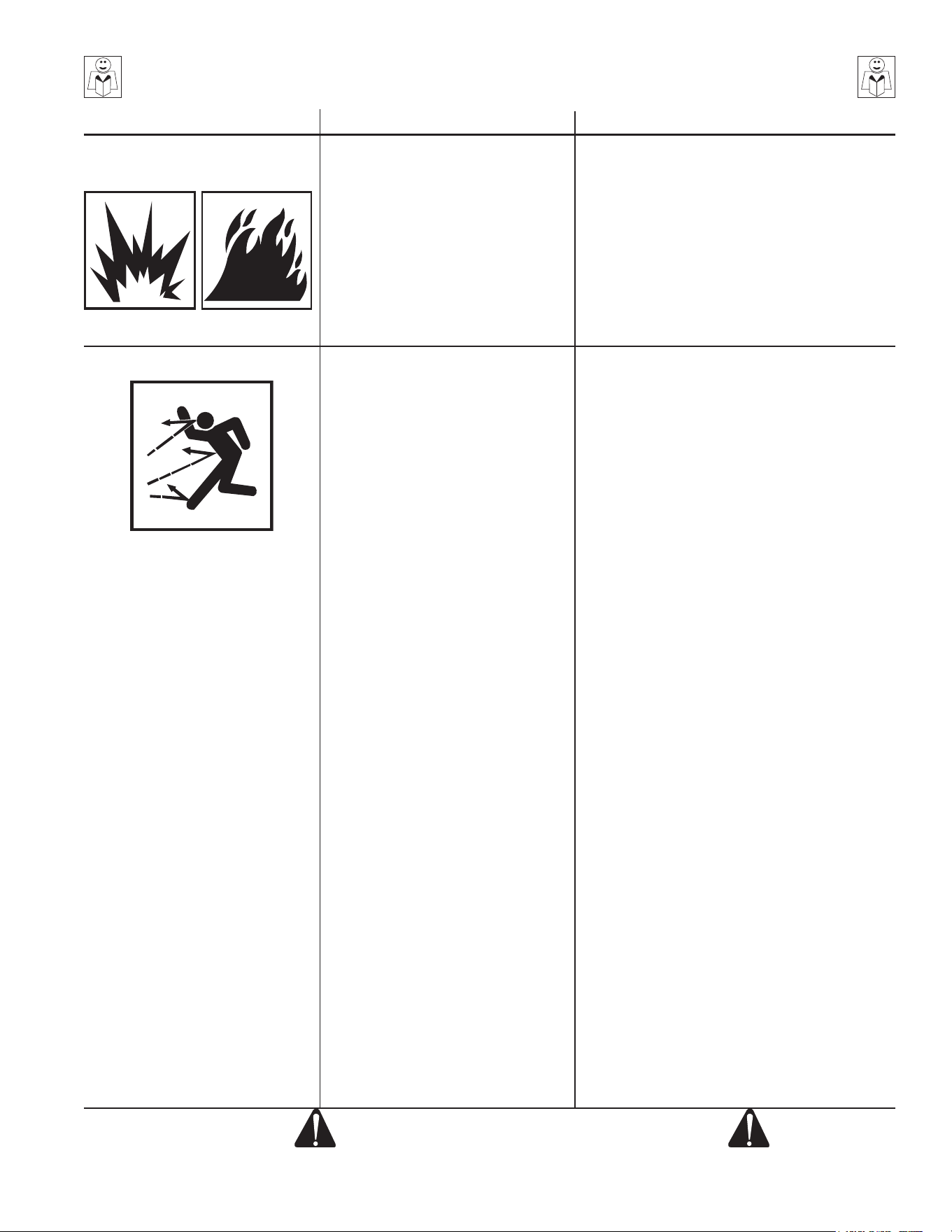
RISK OF
EXPLOSION OR FIRE
Serious injury or death may occur
from normal sparks in the motor.
Serious injury or death may occur
from absorption of flammable
materials.
Injury may occur from unit
overheating.
Always operate PWR System in a well
ventilated area free of ammable vapors,
combustible dust, gases or other combustible
materials.
Do not pick up any ammable materials such as
gasoline or anything that is burning or smoking
such as cigarettes, ashes, etc.
Always unroll the Power Cord before operating.
Using a rolled-up power cord could result in
low voltage or overheating.
HAZARD
RISK OF BODILY INJURY
Injury may occur from the PWR
System.
Keep the suction nozzle away from the body,
especially the eyes, ears, nose and mouth.
Do not use this unit to pickup endangering
dusts or substances.
Stay alert-watch what you are doing. Do not
operate the unit when fatigued or under the
inuence of alcohol or drugs.
Wet surfaces can be slippery, wear protective
foot gear and keep good footing and balance
at all times.
Direct supervision is necessary when children
operate this PWR System. Do not allow to be
used as a toy.
DO NOT leave operating unit unattended. Shut
o the PWR System and disconnect from the
power source before leaving.
Know how to stop the PWR System. Be
thoroughly familiar with controls.
Before servicing the unit: turn the unit o and
allow the unit to cool down. Service in clean,
dry, at area. Block the wheels to prevent the
unit from moving (with optional kit).
Use of this machine for anything not specied
in this manual may be dangerous and must
be avoided. The manufacturer cannot be held
responsible for any damage/injury caused to
persons or property because of the incorrect
use of the machine due to procedures being
used which are not specied in this manual.
SAVE THESE INSTRUCTIONS
Do not put any object into openings. Do not use
with any opening blocked; keep free of dust,
lint, hair, and anything that may reduce air ow.
Keep hair, loose clothing, ngers, and all parts
of body away from openings.
Use only as described in this manual. Use only
manufacturer's recommended attachments.
Use extra care when cleaning on stairs.
6 PWR System Operator's Manual
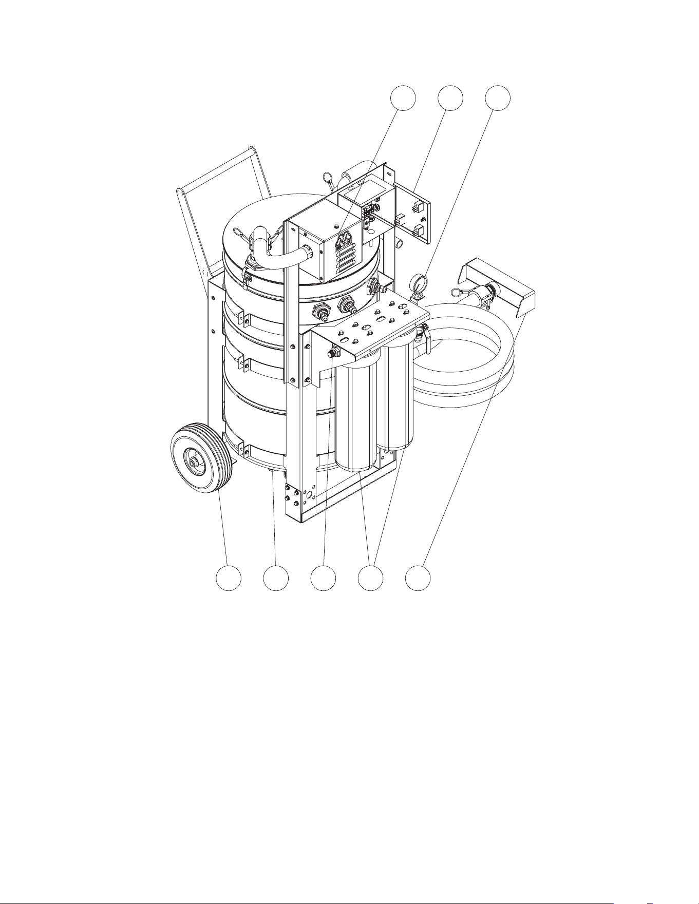
1. Vacuum
2. Control Box
3. Pressure Gauge
4. Wheel Kit
5. Tank Drain
6. Outlet
7. Filter
8. Suction End
PORTABLE WATER RECOVERY UNITS
6
7
84
21 3
5
FEATURES LISTING
PWR System Operator's Manual 7
ATTIRE:
Proper attire is essential to your safety. It is advised to utilize whatever means
necessary to protect eyes, ears and skin. Additional safety attire may be required
when using the PWR with other cleaning equipment (like a pressure washer).
SET-UP:
1. This unit should only be placed on a level surface to ensure unit does not tip
over while operating. NEVER spray water directly on unit!
2. Do not place unit in an area:
a. Where there is evidence of an oil or gas leak.
b. Where ammable gas vapors may be present.
3. Do not allow the unit to be exposed to extreme weather like rain, snow or freezing
temperatures. If any part of the unit becomes frozen; excessive pressure may
build up in the unit which could cause damage to the unit or individuals around
the unit.
4. Before each use, make sure the vacuum hose and pump out line are free of all
obstructions.
5. The system is supplied with a 6” x 20’ water dyke to be placed in a location
that will pool the wash water so that the vacuum system can recover the water.
DO NOT DIRECTLY CONNECT HOSE TO FILL PORT, THE DYKE IS NOT
PRESSURE RATED AND WILL BE DAMAGED.
a. Unroll the water dyke and place in the location where it is going to be used.
Place opening end on the higher side of the grade.
b. To ll the water dyke open the cap and hold the end of a garden hose or
pressure washer hose without nozzle inside the inlet port and turn water on.
Fill to half to three quarters of the way full for best results.
c. Secure the cap and the dyke is ready for use.
6. If oils will be present in the water that is to be recovered by the PWR system,
place a clean oil sock in either the collection drum (must be xed in place so it
does not interfere with oats) or the nal holding tank for the water.
7. The vacuum line has a 90° cam coupler and a straight cam coupler on it and will
be attached between the barrel inlet and the water pickup.
a. The straight coupler attaches to the water pickup and the 90° coupler attached
to the barrel inlet.
b. The vacuum hose must be uncoiled when vacuuming to insure solids do not
settle in the vacuum line and to achieve the maximum vacuum possible.
8. The discharge connection is a standard garden hose tting. Connect a garden
hose to the discharge and direct the discharged water line either into a holding
tank or to an appropriate discharge location.
NOTE: Ensure all materials are disposed of according to Federal and State EPA
Standards.
INSTALLATION & PREPARATION
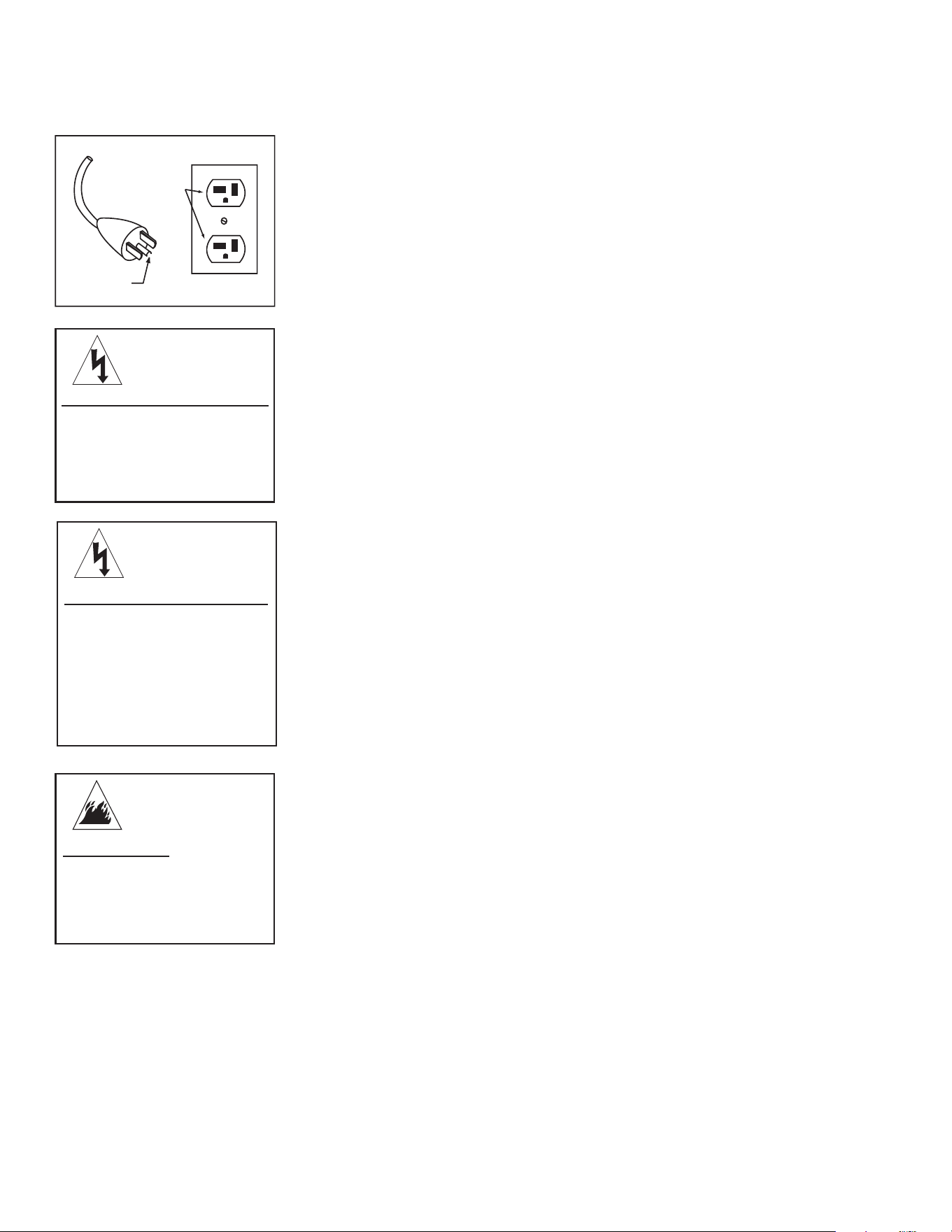
WARNING
Where ammable gas vapors
may be present. An electrical
spark from the motor may
cause a re.
RISK OF FIRE!
WARNING
Where the unit may be
exposed to rain, snow or
immersed in water. Water
may inltrate the electrical
system causing an
electrical hazard.
RISK OF ELECTRIC SHOCK!
8 PWR System Operator's Manual
POWER CORD CONNECTION:
1. Make sure all switches are in the “O” position.
2. Ensure electrical supply is identical to the specications listed on the Portable
Water Reclaim (PWR) data plate.
3. GROUNDING INSTRUCTIONS: This product must be grounded. If it should
malfunction or break down, grounding provides a path of least resistance for
electric current to reduce the risk of electric shock. This product is equipped
with a cord having an equipment-grounding conductor. The plug must be
plugged into an appropriate outlet that is properly installed and grounded in
accordance with all local codes and ordinances.
4. DANGER: Improper connection of the equipment-grounding conductor can
result in a risk of electrocution. Check with a qualied electrician or service
personnel if you are in doubt as to whether the outlet is properly grounded. Do
not modify the plug, if it does not t the outlet; have a proper outlet installed
by a qualied electrician.
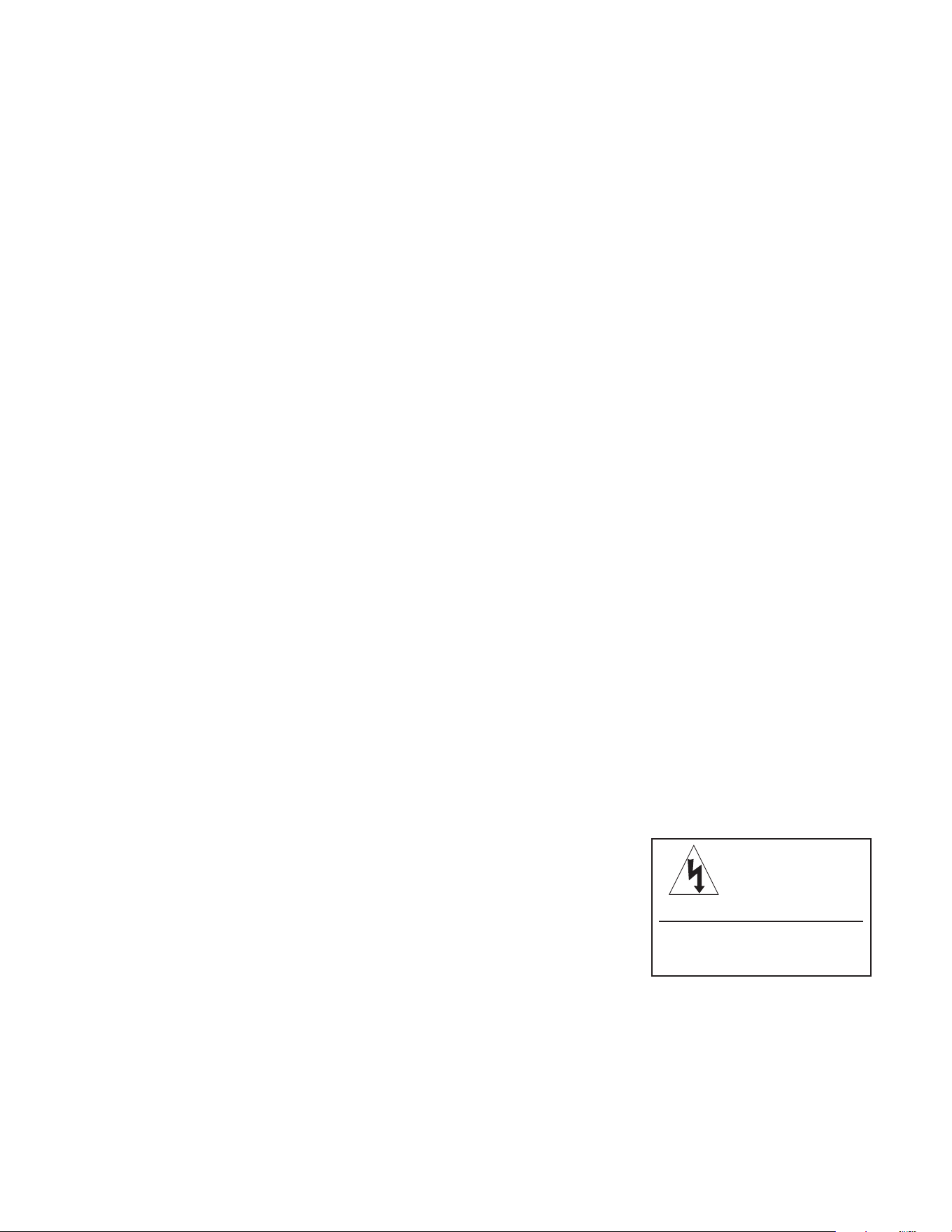
5. The PWR system is for use on a nominal 120 VAC circuit and has a grounding
attachment plug (see Fig. A). Make sure that the PWR system is connected
to an outlet having the same conguration as the plug. No adapter should be
used with the PWR system.
6. Unroll the power cord before plugging it into a grounded outlet.
7. Ensure the area between the PWR and cord and the outlet is kept dry.
INSTALLATION & PREPARATION
GROUNDING
PIN
GROUNDED
OUTLET
RISK OF ELECTRIC SHOCK!
WARNING
Improper connection of
the equipment-grounding
conductor can result in a
risk of electric shock.
WARNING
If use of an extension
cord is required, use only
extension cords having
an electrical rating not
less than the rating of
the product. Do not use
damaged extension cords.
RISK OF ELECTROCUTION!
CAUTION
A wound-up power cord
may result in low voltage
and possible overheating
causing a re.
RISK OF FIRE!
FIG. A
PWR System Operator's Manual 9
OPERATION:
1. Please observe the following precautions while using your Portable Recovery
System:
a. Do not place any object in the PWR vacuum openings. Ensure all
openings remain unobstructed and free of debris or anything that may
reduce air ow.
b. Aggressive solvents or detergents should not be used. DO NOT operate
the unit if you see any foam/liquid leaking from the vacuum. DO NOT
resume operation until the unit has been inspected and repaired by a
qualied service person.
c. If the equipment should overturn, it is recommended that the PWR be
placed upright before turning it o.
Note: The PWR is supplied with a barrel drain, be sure the drain valve is closed
before starting the unit. The PWR will not operate properly with the
barrel drain open.
2. With the PWR system setup complete and the water pickup positioned in
an area where water will pool; move all the ON/OFF switches to the “ON”
position.
a. As water is recovered and the barrel lls, the low level oat will rise
allowing the transfer pump to turn on.
i. At this point, if the transfer pump is switched on, water will be
pumped through the lters and discharged to a sanitary sewer or
holding tank.
ii. The lters should be replaced or cleaned as the pressure builds in
the lter canister to ensure optimal performance from the transfer
pump.
NOTE: Ensure all materials are disposed of according to State and Federal
EPA Standards.
b. If more water is being vacuumed up than can be pumped out by the
transfer pump the high level oat in the barrel will be actuated and will
turn the vacuum motor o. The vacuum will remain o until the barrel
is emptied enough for the oat to go down.
SHUTDOWN:
1. When recovery application is completed, allow the transfer pump to drain
the barrel until the low level oat turns the unit o then turn the on/o switch
to the “O” position.
2. Disconnect the power cord from the receptacle and roll up the cord.
3. Take the unit to an area that is acceptable for clean out and meets all local
and federal regulations for discharge.
4. Open the drain on the bottom of the barrel.
5. Remove the lid o the barrel and remove the lter housings using the lter
wrench.
a. Dump the water remaining from the lter housings and remove lters
for cleaning and drying or disposal. Remember to replace lter before
next operation.
6. Rinse the barrel and lter housing out, then allow to air dry.
7. When re-attaching lter housings use Vasoline or similar lubricant on the
o-rings to help seal the housing to the lids.
8. Wipe down the exterior of the PWR system and store indoors to extend the
life of the unit.
OPERATING INSTRUCTIONS
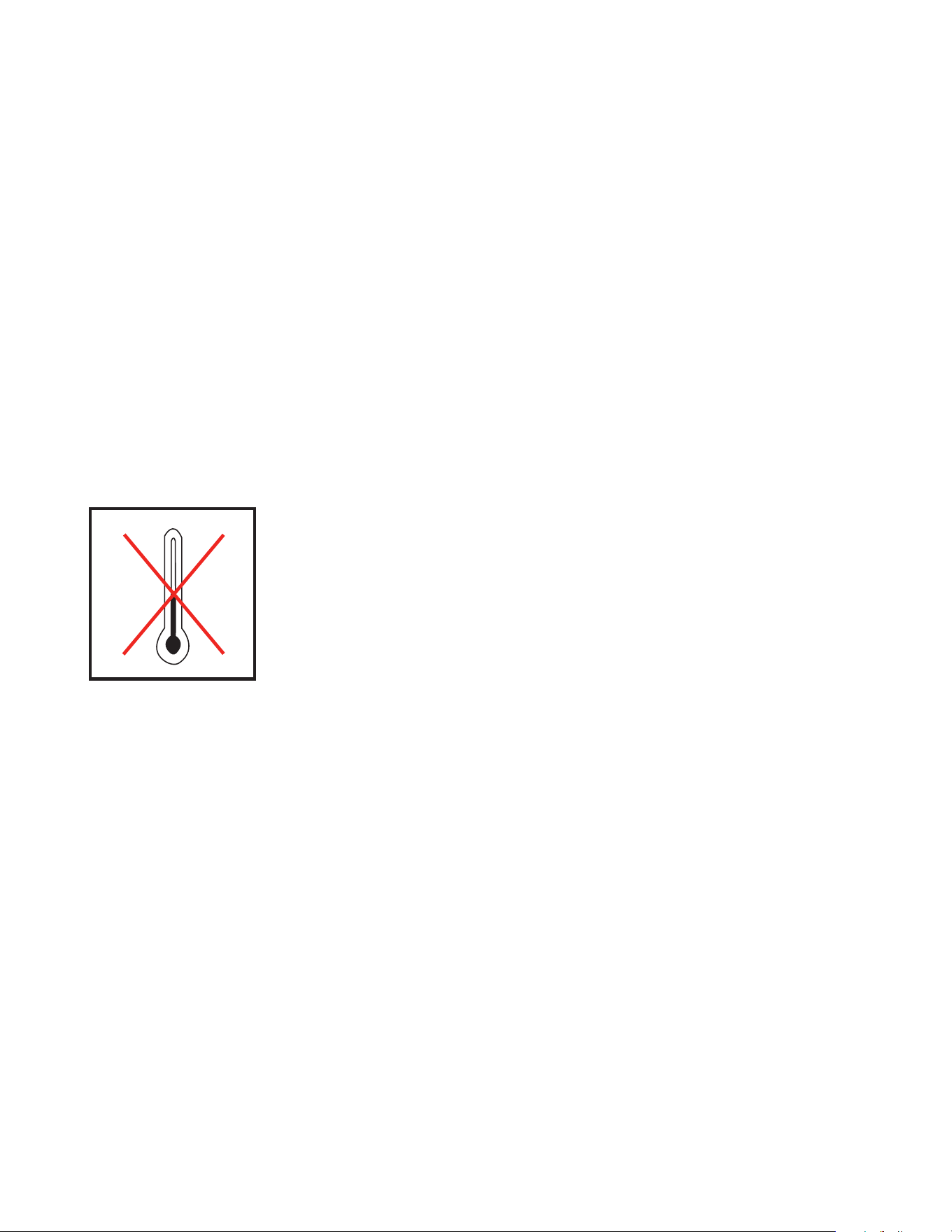
WARNING
Do not yank on any cord to
disconnect.
RISK OF ELECTROCUTION!
10 PWR System Operator's Manual
STORAGE & MAINTENANCE
Specic Maintenance:
Water Pickup: Inspect openings and make sure they are free of debris and
unobstructed.
Vacuum Hose: Periodically rinse the vacuum hose out by ushing water
though the hose as some solids may remain in the hose after use and may
cause an obstruction later on.
Collection Barrel: Remove the lid and thoroughly rinse the inside and
outside of the barrel down with fresh water. Allow to dry completely before
attaching the lid.
Filter Housing: Clean or replace lters as needed during operation. Close
discharge valve and use wrench to loosen housing. Filters are heavy
when lled with water, prepare to support the weight as the housings are
detached from the lids. Double check o-ring position and re-lubricate as
needed when re-attaching the housings to the lids.
Pumps: The vacuum and transfer pumps should not require any routine
maintenance but should be taken to a qualied service technician if pumps
performance decreases or unusual sounds are present.
Water Dyke: Inspect for holes before each use and if present patch holes
or replace as necessary.
Cam Couplers: Inspect the o-ring in the female portion of the cam coupler
periodically and replace the o-ring if it is cracked or damaged in any way.
Winterizing:
It is recommended that this unit be stored in an indoor location that is
maintained above freezing temperatures and out of the elements. For
storage and transportation purposes in subfreezing ambient temperatures,
it will be necessary to winterize this unit for the following reason:
1. Water freezing and expanding as ice could crack piping, the collection barrel
or the transfer pump housing.
To winterize follow these steps:
1. Drain the entire system of water, including all piping and the transfer pump
housing and allow all components in the unit to dry completely before
reassembly.
2. During reassembly leave all unions loose and valves open giving ice a place
to expand to incase some water is left in the system.
Starting Unit after Extended Storage:
1. Be certain the unit is not plugged into the power source.
2. Prior to restarting the unit, inspect all parts to make sure they are not
damaged and need replacing.
3. Follow start up procedures and continue use as normal.
STORAGE & MAINTENANCE
32˚F 0˚C
PWR System Operator's Manual 11
TROUBLESHOOTING
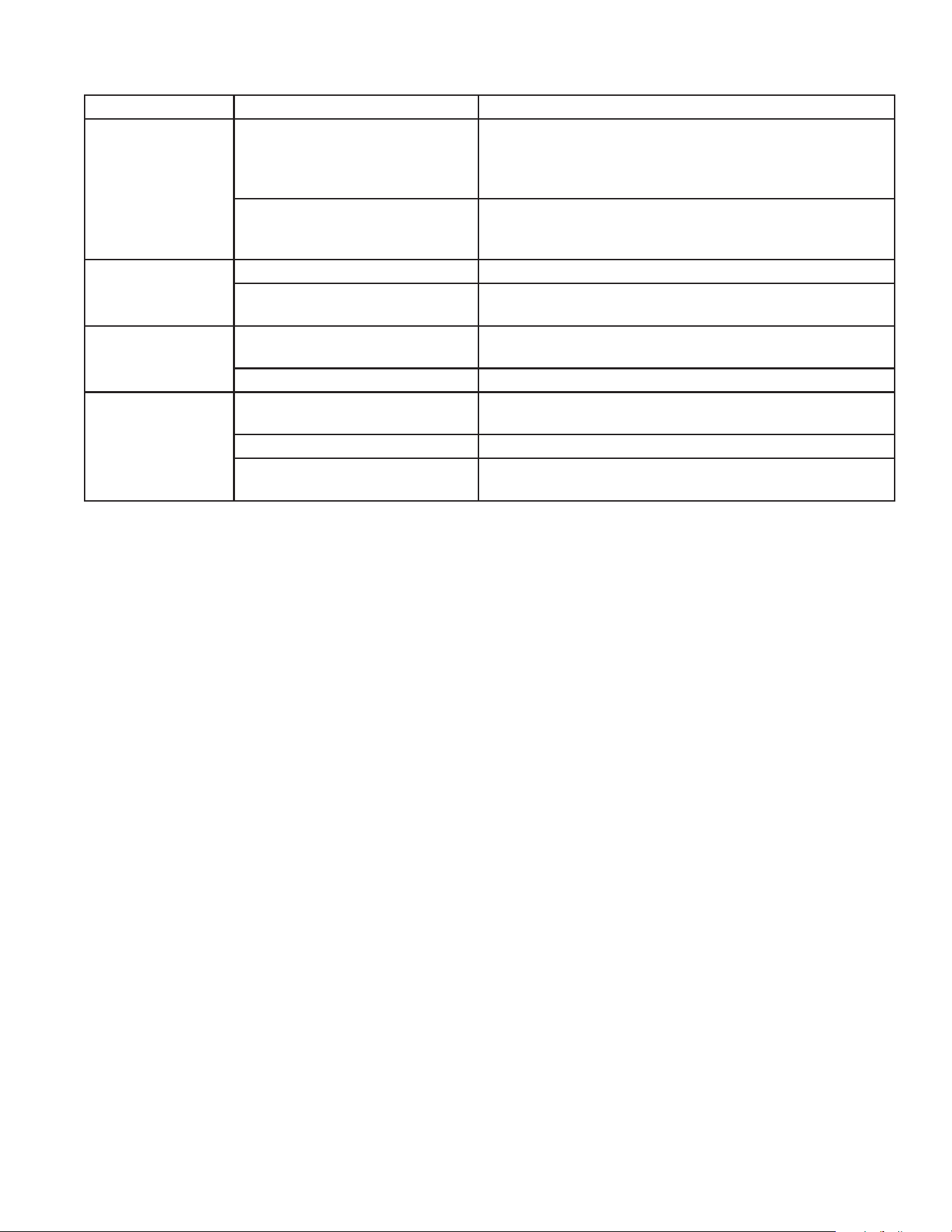
Symptom Probable Cause Remedy
PWR Unit will not
turn on.
Power cord is disconnected. Ensure the power cord is securely connected to the unit
and to the power source. If using an extension cord;
ensure the power cord and extension cords are securely
connected.
Fuse Blown Turn o all switches and unplug the unit. Check the pumps
to make sure they have no obstructions, if so clear them.
Then replace the fuse and resume use.
Vacuum Motor will
not start.
Brushes on motor are worn. Contact your dealer or customer service.
Collection Barrel is full. Wait for transfer pump to catch up or open drain valve until
high level oat can go down.
Inadequate Suction Flexible hose is obstructed, cut or
damaged.
Clean or replace exible hose.
Water pick up is clogged. Clean obstructions.
Transfer Pump not
pumping.
Collection Barrel empty. Wait for the low level oat to rise and the pump will turn
on.
Filters are blinded Replace or clean blinded lters.
Discharge line is obstructed. Unhook discharge hose and inspect, clear obstruction and
reattach.
12 PWR System Operator's Manual
SPECIFICATIONS
Model Number PWR-10-0ME1
Vacuum Motor 1500W 3-stage tangential
Voltage 120V
Amperage 9 amps
Air Flow 110 CFM
Lift 145 in H
2
O
Transfer Pump 1/3hp Submersible
Voltage 120V
Amperage 8 amps
Head 23 feet
Flow Rate 31 GPM
Collection Barrel Capacity 45 gallons
Electrical Cord 25 feet
Fuse 25 amps
Dimensions (L x W x H) 30” x 30” x 42”
Weight (empty) 60 lb

PWR System Operator's Manual 13
NOTES
SERIAL NUMBER DESCRIPTION
#30005269 WX-0107 OBSOLETED, WX-0109 CHANGED TO DUAL BAG FILTERS
#30007417 LARGER DRAIN, REDSIGNED VACUUM AND CONTROL BOX
#30007594 UPGRADED WIRING
#30008169 CHANGED FILTERS ON WX-0109.
#30008283 CHANGED SUMP PUMP TO GOULDS 3-0468
14 PWR System Operator's Manual
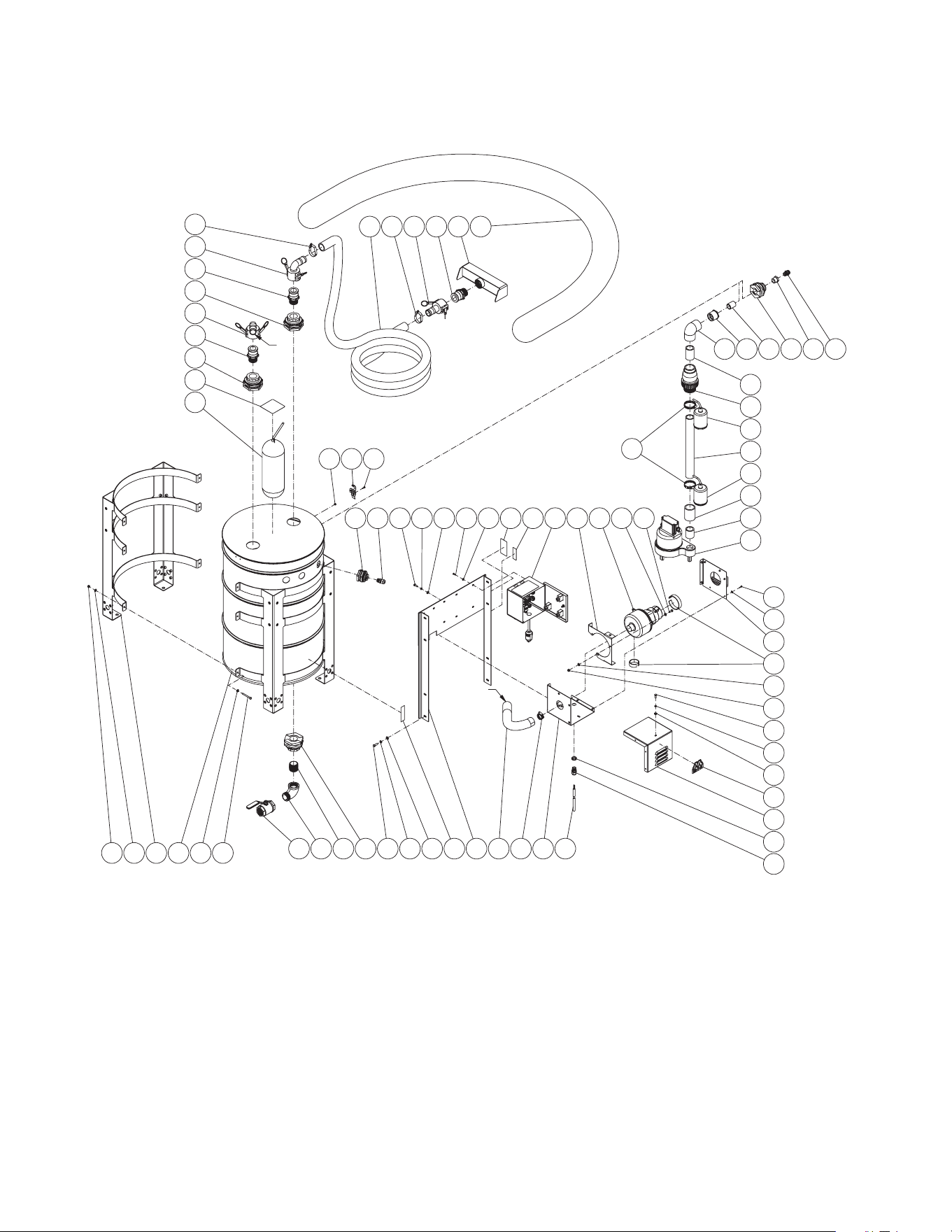
PWR-10-0ME1 (AFTER SERIAL #30008283)
52
9
53
54
50
49 28
1 2
3
4 2
5
12
1110
17
22
14
24 23
2
48
45 40
36
35
34 32 31 29
58535756
9
53
54
44
43 2
24
A
35
39
33 30
13
20
A
59
51
16
23
2
19
50'
24"
24"
16 1/4"
2 3/4"
15
24
19
18
1
2
21
26
27
28
28
27
9
8
7
6
47
46
42
37
38
41
55
55
25
5 7/8"
9 7/8"
PWR System Operator's Manual 15
PWR-10-0ME1
PWR-10-0ME1 060222
FRAME ASSEMBLY
ITEM DESCRIPTION Mi-T-M # QTY
1 LOCKNUT 30-5155 9
2WASHER 28-0121 25
3 BARREL STAND 20-1266A18 2
4 55 GALLON DRUM 12-0237 1
- LID 33-0670 1
5 BOLT 27-8996 6
6 BALL VALVE 22-0499 1
7 ELBOW 24-0354 1
8 NIPPLE 24-0355 1
9 BULKHEAD (INC. 26-0421 GASKET) 55-1686 3
10 BOLT 27-5067 4
11 LOCKWASHER 29-1007 4
12 WASHER 28-0122 4
13 DECAL - TANK DRAIN (SEE 71-0110) N/A 1
14 MOUNTING BRACKET 20-1418A18 1
15 HOSE *(TWO FEET REQUIRED) 15-0329 1
16 HOSE CLAMP 42-0018 1
17 VACUUM BOX 20-1415A18 1
18 CORD *(TWO FEET REQUIRED) 32-0074 1
19 STRAIN RELIEF 32-0437 4
20 ELECTRICAL LOCKNUT 32-0108 1
21 VACUUM BOX COVER 20-1414A18 1
22 DECAL - #2M 34-2168 1
23 LOCKWASHER 29-1006 7
24 BOLT 27-5016 10
25 FOAM PADDING *(TWO FEET REQUIRED) 26-0303 1
26 VACUUM BOX SIDE 20-1416A18 1
27 WASHER 28-0120 12
28 SCREW 27-5033 16
29 ADAPTER 23-0136 1
30 REDUCER 55-1234 1
31 BULKHEAD (INC. 25-0482 GASKET) 55-1286 1
32 NIPPLE 55-1274 1
33 REDUCER 55-1629 1
34 ELBOW 55-1609 1
35 PIPE *(TWO FEET REQUIRED) 55-1600 1
36 CHECK VALVE 55-1652 1
37 FLOAT 32-0529 1
38 FLOAT 32-0527 1
39 COUPLER 55-1614 1
40 TOE NIPPLE 55-1679 1
41 PUMP-SUBMERSIBLE 3-0468 1
42 HOSE CLAMP 42-0060 2
43 VACUUM 2-0190 1
44 VACUUM BRACKET 20-1417A18 1
45 CONTROL BOX ASSEMBLY N/A SEP.1
46 DECAL - PROP 65 N/A 1
47 DECAL - SILVER STICKER N/A 1
48 BULKHEAD (INC. 25-0506 GASKET) 55-0886 3
49 LATCH 33-0528 2
50 NUT 30-9516 4
51 OIL BOOM 33-0529 2
52 DECAL - NONPOTABLE WATER (SEE 71-0110) N/A 1
53 ADAPTER 55-0024 3
54 COUPLER 55-1681 2
55 HOSE CLAMP 42-0027 2
56 HOSE *(FIFETY FEET REQUIRED) 15-0223 1
57 COUPLER 55-0053 1
58 VACUUM END 21-0306 1
59 WATER DIKE 33-0520 1
- DECAL SET 71-0110 1
*MUST ORDER IN ONE FOOT LENGTHS
16 PWR System Operator's Manual
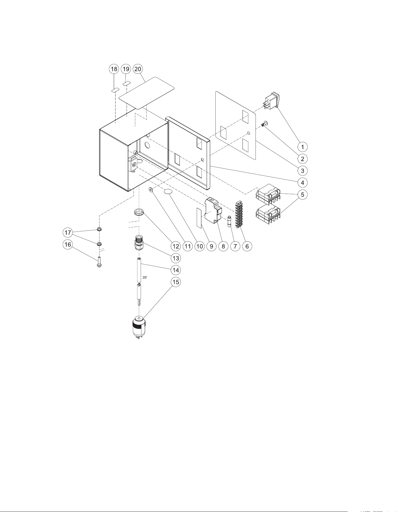
CONTROL BOX ASSEMBLY (AFTER SERIAL #30007594)
PWR System Operator's Manual 17
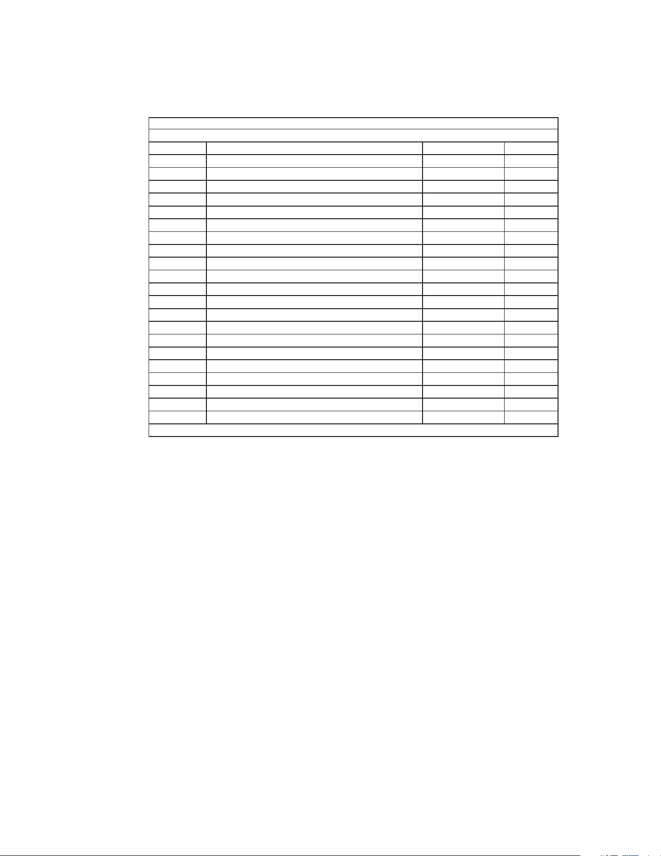
CONTROL BOX ASSEMBLY
CONTROL BOX ASSEMBLY PWR-10-0ME1 101416 MLK
CONTROL BOX ASSEMBLY
ITEM DESCRIPTION Mi-T-M # QTY
1 ROCKER SWITCH 32-0669 3
2FASTENER 33-0197 1
3 DECAL- PWR CONTROL BOX (SEE 71-0110) N/A 1
4 CONTROL BOX 20-1419A18 1
5 RELAY 32-0633 2
6 TERMINAL STRIP 32-0436 1
7 FUSE 32-1162 1
8 FUSE HOLDER 32-0473 1
9 VELCRO STRIP *(ONE FOOT REQUIRED) 36-0011 1
10 DECAL- GROUND PICTORIAL (SEE 71-0110) N/A 1
11 RUBBER WASHER 26-0259 1
12 ELECTRICAL LOCKNUT 32-0108 5
13 STRAIN RELIEF 32-0437 5
14 CORD *(TWENTY FEET REQUIRED) 32-0445 1
15 PLUG 32-0121 1
16 BOLT 27-8898 1
17 NUT 30-3022 2
18 DECAL - 115 VOLT (SEE 71-0110) N/A 1
19 DECAL - 1 PHASE (SEE 71-0110) N/A 1
20 DECAL - RISK OF ELECTROCUTION (SEE 71-0110) N/A 1
- DECAL SET 71-0110 1
*MUST ORDER IN ONE FOOT LENGTHS
18 PWR System Operator's Manual
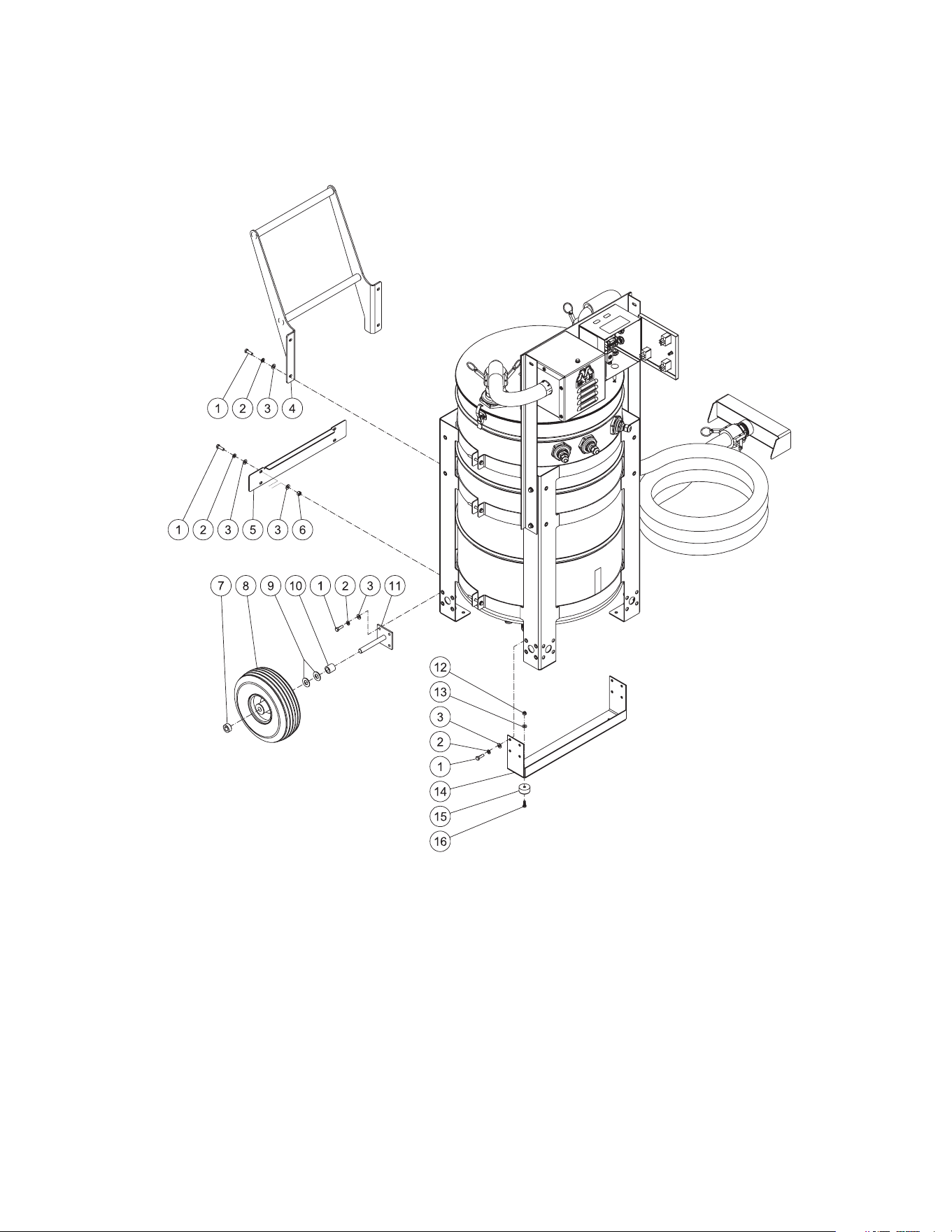
WX-0106 WHEEL KIT OPTION
PWR System Operator's Manual 19
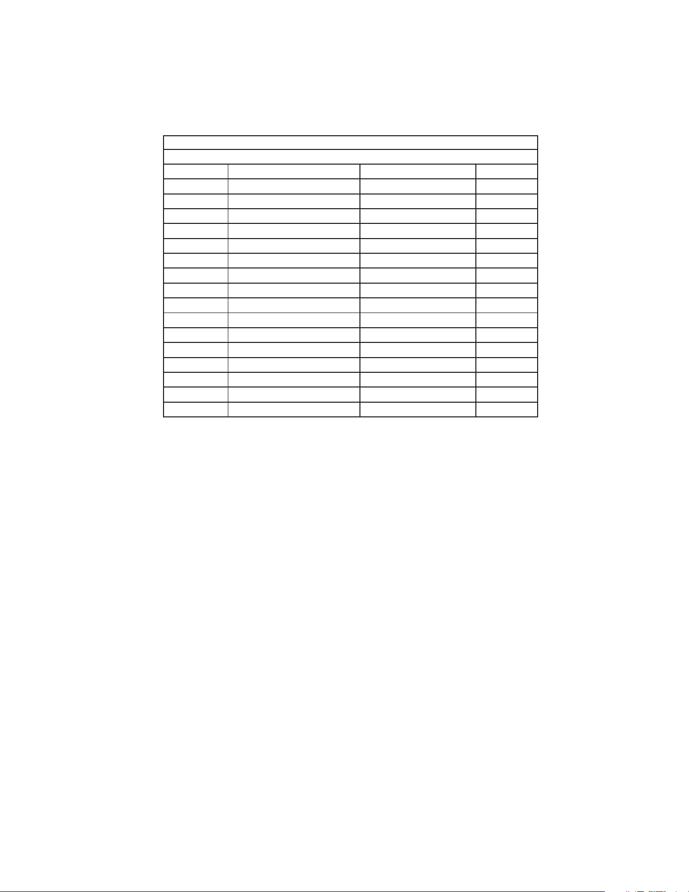
WX-0106 WHEEL KIT OPTION
WX-0106 120915 MLK
OPTION - WHEEL KIT
ITEM DESCRIPTION Mi-T-M # QTY
1 BOLT 27-5067 24
2 LOCKWASHER 29-1007 24
3WASHER 28-0122 28
4 HANDLE 7-0231A18 1
5 KICK PLATE 20-1273A18 1
6 LOCKNUT 30-5158 4
7 COLLAR 33-0351 2
8WHEEL 14-0130 2
9WASHER 28-0008 4
10 SPACER 62-0188 2
11 AXLE 20-0670A01 2
12 LOCKNUT 30-0155 2
13 WASHER 28-0002 2
14 ISOLATOR FOOT 20-1271A18 1
15 ISOLATOR 14-0069 2
16 BOLT 27-0015 2
20 PWR System Operator's Manual
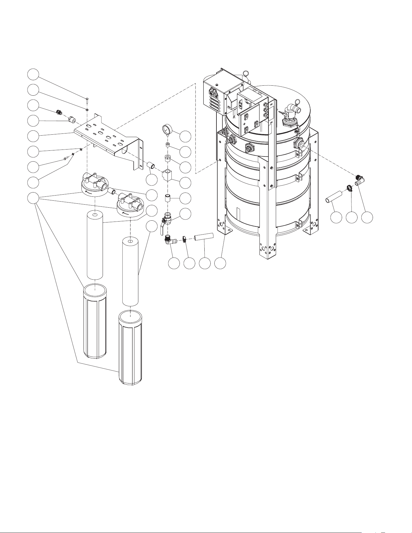
WX-0109 DUAL FILTER OPTION (AFTER SERIAL #30008169)
12
13
10
9
8
7
6
5
1 2 3
19
8
18
17
16
15
123
14
4
22"
11
6
17
20
PWR System Operator's Manual 21
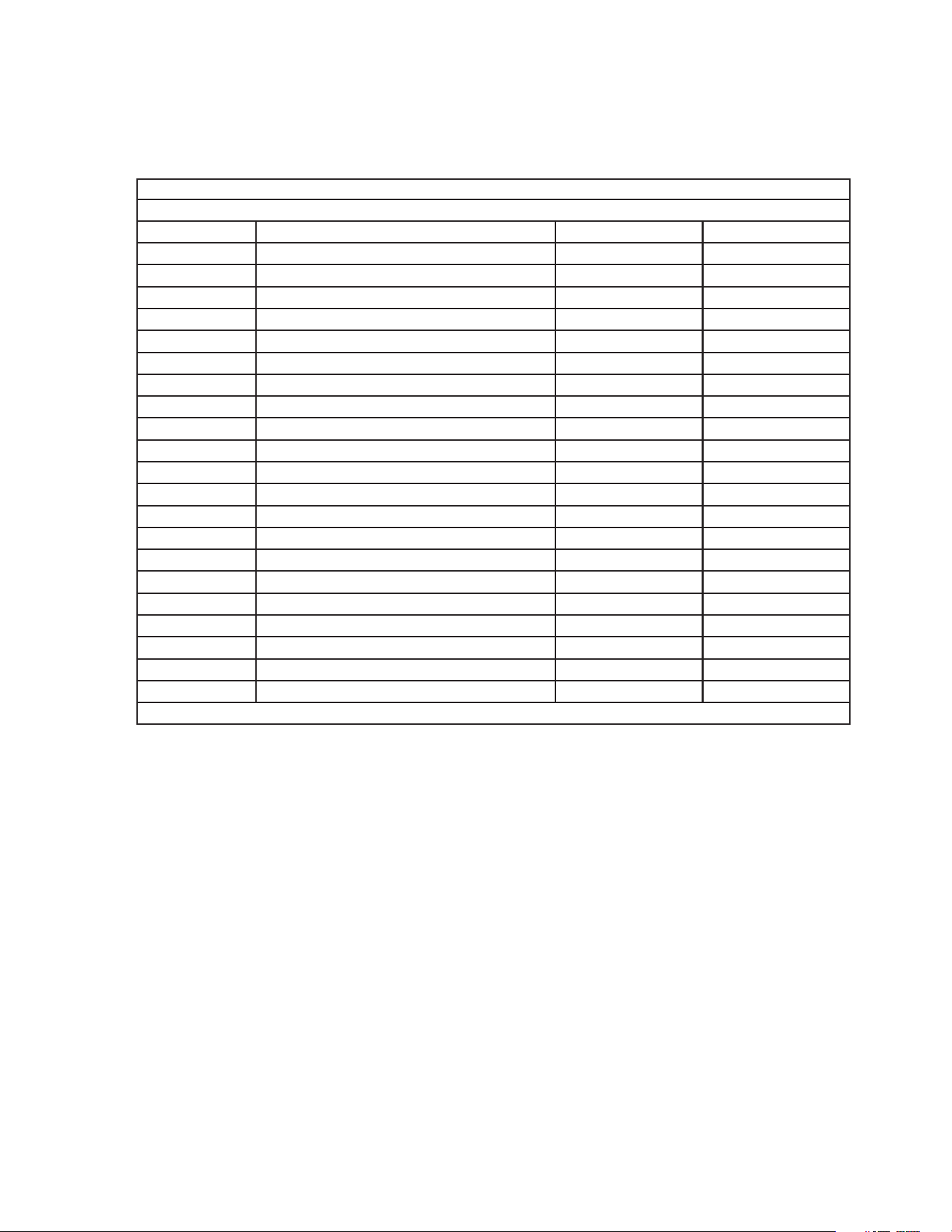
WX-0109 DUAL FILTER OPTION
WX-0190 032921
OPTION- FILTERS
ITEM TITLE PART # QTY
1 ELBOW 55-1293 2
2 HOSE CLAMP 42-0018 2
3 HOSE *(TWO FEET REQUIRED) 15-0290 2
4 PORTABLE WASH RECOVERY UNIT N/A SEP
.1
5 BALL VALVE 22-0344 1
6 NIPPLE 23-0094 2
7 BRASS TEE 23-0149 1
8 REDUCER 23-0226 2
9 REDUCER 23-0056 1
10 PRESSURE GAUGE 22-0476 1
11 NIPPLE 55-1274 1
12 FILTER 19-0302 1
13 FILTER 19-0216 1
14 FILTERS HOUSING 19-0634 2
15 LOCKWASHER 29-1007 4
16 BOLT 27-5067 4
17 WASHER 28-0122 12
18 FILTER BRACKET 20-1663A18 1
19 ADAPTER 23-0136 1
20 BOLT 27-5276 8
- FILTER WRENCH 33-0378 1
*MUST ORDER IN ONE FOOT LENGTHS
22 PWR System Operator's Manual
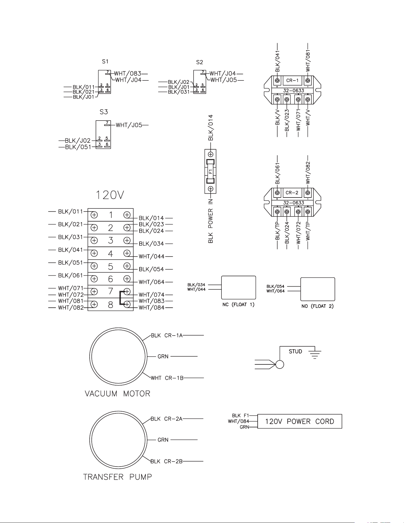
WIRING DIAGRAM (BEFORE SERIAL #3007594)
PWR System Operator's Manual 23
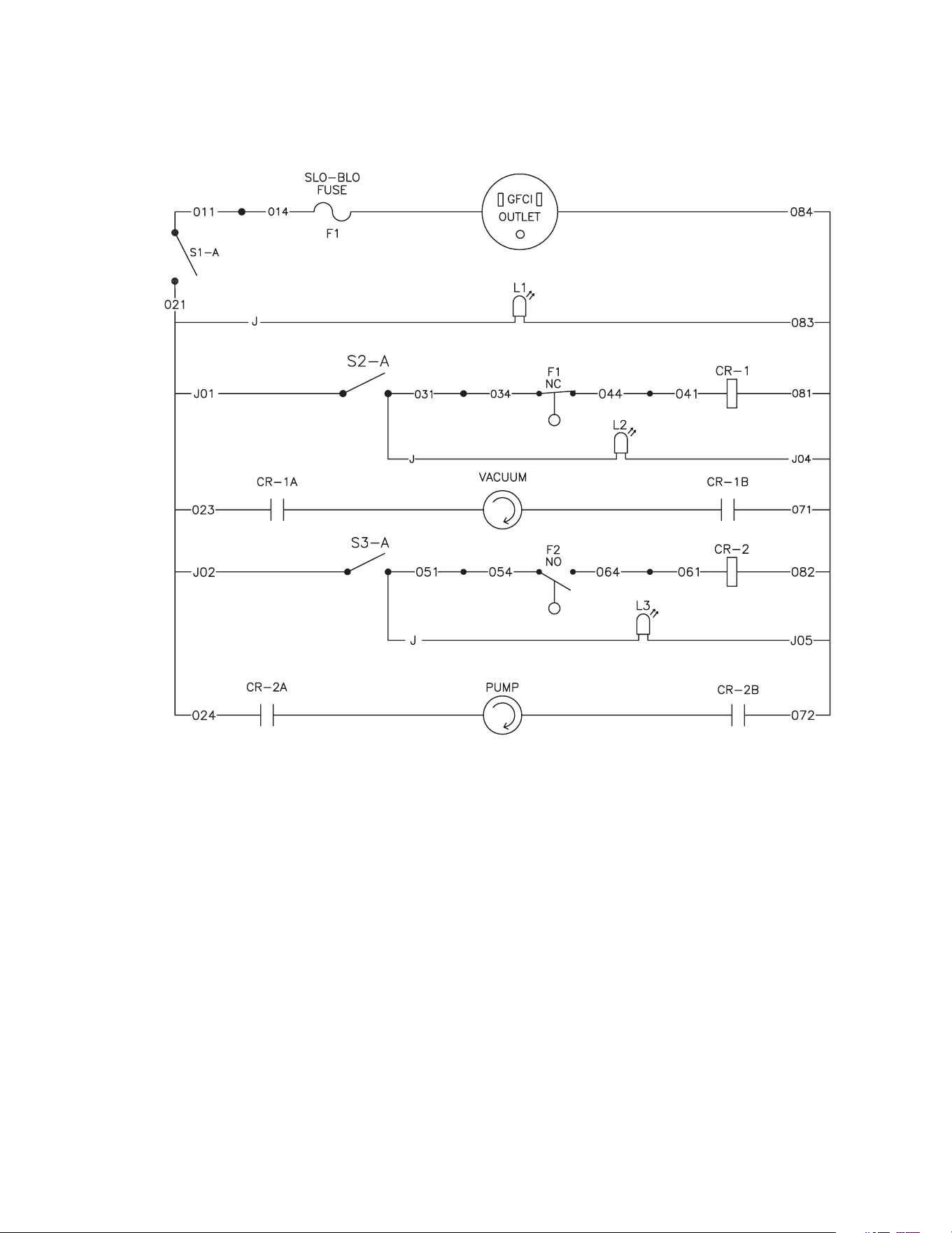
LADDER DIAGRAM (BEFORE SERIAL #3007594)
24 PWR System Operator's Manual
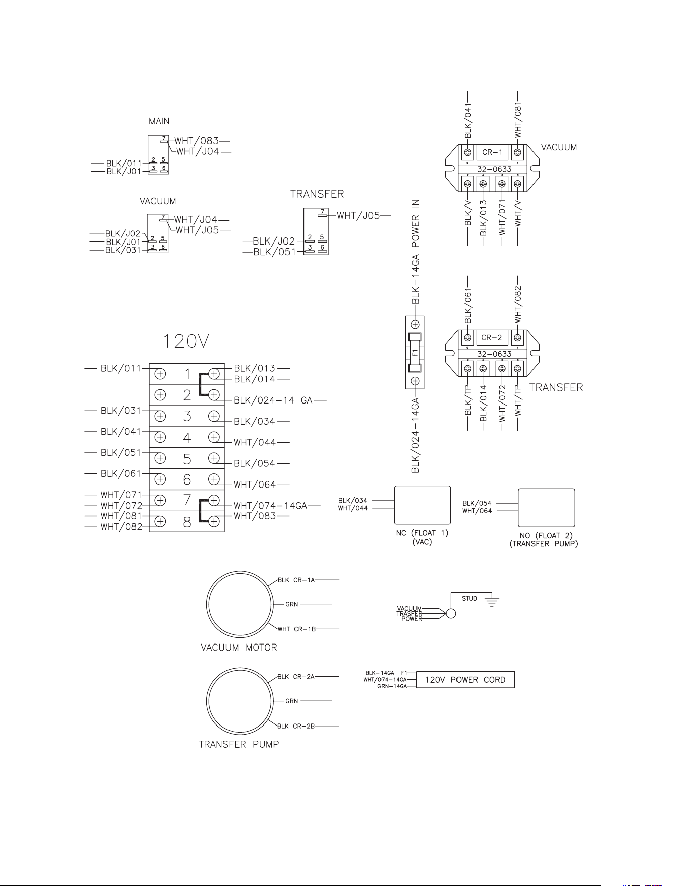
WIRING DIAGRAM (AFTER SERIAL #30007594)
PWR System Operator's Manual 25
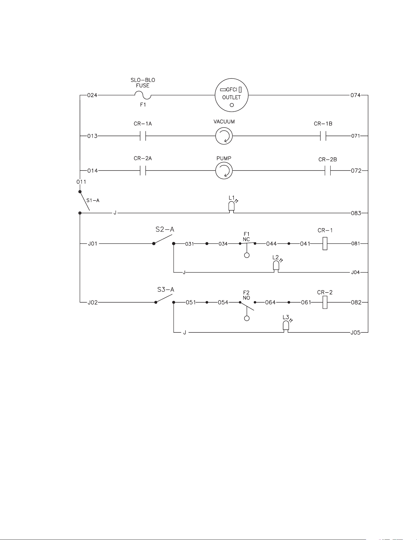
LADDER DIAGRAM (AFTER SERIAL #30007594)
26 PWR System Operator's Manual
STATEMENT OF WARRANTY
FOR Mi-T-M PORTABLE WATER RECOVERY SYSTEM
Mi-T-M warrants all parts (except those referred to below) of your new PWR System to be free from defects
in materials and workmanship for One (1) Year from the date of original purchase.
Defective parts not subject to normal wear and tear will be repaired or replaced at Mi-T-M's option during the
warranty period which upon examination is disclosed to have been defective in material or workmanship. In
any event, reimbursement is limited to the purchase price paid.
EXCLUSIONS
1. This warranty does not cover parts damaged due to:
-normal wear, misapplication, modications/alterations, abuse,
-operation at other than recommended speeds, pressures or temperature,
-the use of caustic liquids,
-chloride corrosion or chemical deterioration,
-uctuations in electrical or water supply,
-operating unit in an abrasive, corrosive or freezing environment.
2. This warranty does not cover parts damaged by failure to follow recommended installation, operating and
maintenance procedures.
3. This warranty does not cover the cost of:
-normal maintenance or adjustments,
-labor charges,
-transportation charges to Service Center,
-freight damage.
4. The use of other than genuine Mi-T-M parts will void warranty. Parts returned, prepaid to Mi-T-M's factory
or to an Authorized Service Center will be inspected and replaced free of charge if found to be defective
and subject to warranty. There are no warranties which extend beyond the description of the face hereof.
Under no circumstances shall Mi-T-M bear any responsibility for loss of use of the unit, loss of time or
rental, inconvenience, commercial loss or consequential damages.
For Service or Warranty consideration, contact
Mi-T-M Corporation, 50 MI-T-M Drive, Peosta, IA 52068-0050
319-556-7484 / 800-553-9053 / Fax 319-556-1235
Monday-Friday 7:30 AM - 5:00 PM CST

PWR System Operator's Manual 27

28 PWR System Operator's Manual
Manufactured by Mi-T-M
50 MI-T-M Drive, Peosta IA 52068
563-556-7484/ Fax 563-556-1235