G
S
M
&
W
i
F
i
N
e
t
w
o
r
k
A
l
a
r
m
S
ys
t
e
m
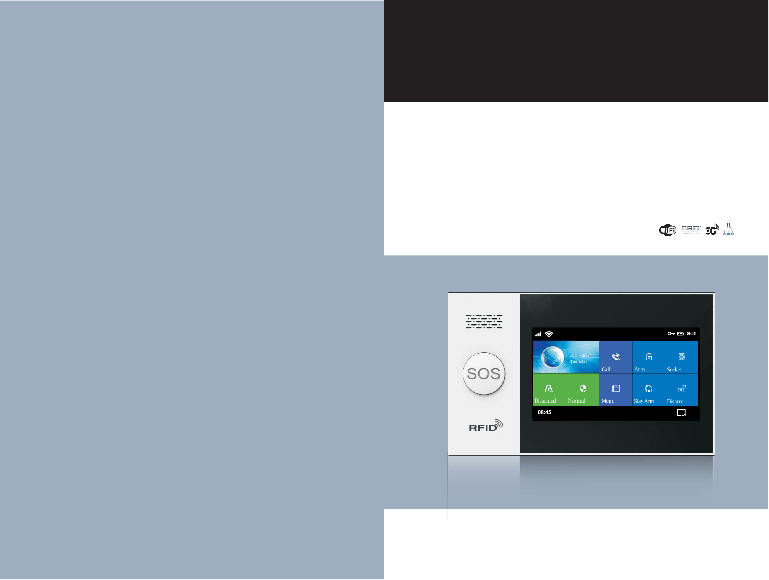
User Manual
Wi-Fi+GSM/3G+GPRS
Content
Overall state
Explanation
Features
Daily Operation Nouns
Appearance and accessories
Front
Back
Side view
Power On/Off
SOS Button
SOS button backlight
Navigating Menus
Main interface function and button description
Menu Structure
Initial usage
Start
System initialization
Menu operation
Phone number setup
Add/Delete remote control
Add/Delete wireless detector(included doorbell alarm)
Add/Delete RFID card
Synchronization with external wireless siren
Wireless Siren Alarm
Smart Home
Record
Timer
Mobile phone APP
1~2
1
1
2
3~7
3
3
4
4
4
4
4
5
6
8~12
8
8
8
8
9
9
10
10
11
11
12
12
13
Remote SMS
Parameter setup
Alarm host name setup
14~16
14
15
Parameter inquiry
Inquire system setting
Inquire system setting2
Alarm phone setup inquiry
Delay setup inquiry
Switch setup inquiry
Remote control/detector/RFID card inquiry
PHONE FUNCTION
Overall state
15
15
Explanation
15
For all the issues stated in this manual:
16
The icon is only valid for the corresponding model host which is
16
configured with the WIFI module.
16
The icon is only valid for user who has applied alarm service in the
16
local network alarm operation service center.
Features
17
› 4.3-inch IPS color display, full capacitive touch screen operation, simple style
man-machine interface and menu guidance design.
DAILY OPERATION
18~19
› The main interface status bar, date and time clock display, host status at a
glance.
Out arm
Stay arm
Disarm
SOS
SMS notification feedback
Alarm and remote monitoring
SMS alarm
Voice alarm and alarm monitoring
Automatic dialing preset phone number when the alarm host alarms
Preset phone number to call alarm host
Mobile app alarm recieving procedure
Receiving alarm by internet monitoring center
18
18
19
19
19
20~21
20
20
20
20
21
21
› Built-in powerful performance CPU master based on 32-bit Cortex-M3 core
› Based on the operating system with multitasking design, with a great user
operation experience.
› WIFI/GSM/GPRS network alarm system, and support APP push/SMS/voice
monitoring/center network etc. multi-channel alarm ways, to ensure the alarm
performance stable and reliable.
› Support SMS arm/Disarm and parameters setting, support invoice arm/Disarm.
› Friendly APP operating experience and user interface, access to latest
equipment working status.
› Up to 100 storage locations for the learning of remotes , RFID and wireless
detectors. 4 wired defense zone
› Support many defense zones name such as of the gate, SOS, bedroom,
window, balcony, perimeter, smoke, gas, carbon monoxide, water leaking, etc.
› Support the main power failure, backup battery power shortage, tamper alarm
and other extended alarm; Support detector low battery alert & tamper alarm
function.
› Door open alert.
Specification
22
Packing list
23
› Support many defense zone types setting such as of entry/exit zone, indoor
zone, perimeter zone, 24-hour zone, doorbell, etc.
› Up to 5 groups preset alarm phone numbers, SMS on/off and voice on/off can
be set respectively.
› External wired alarm connectors: 1 channel external wireless siren, 8 channel
alarm linked wireless intelligent socket.
› APP or host can control several socket, so control the home electrical
appliances.
› Support timing arm and disarm.
› Can store and query several daily operation records and alarm records.
› GSM network automatic school, to ensure the clock is always accurate
› Support multi-language menu display, voice prompts and alarm SMS settings.
1
› Can record 20 seconds message and alarm voice.
› Telephone function, support 5 groups re-dial number.
› Excellent APP operation feeling and user interface, get the device working
status anytime.
› Arm/disarm, host alarm to mobile app.
APPEARANCE AND ACCESSORIES
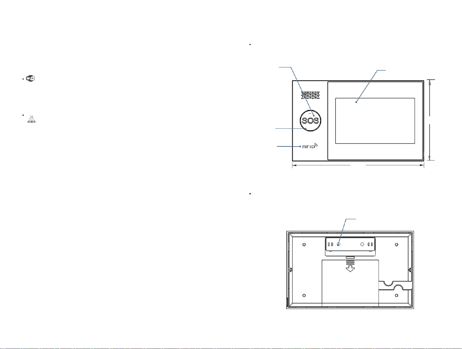
Front
› Support APP arm/disarm remotely, parameter setting, Parts management and
intelligent socket control.
SOS button
Capacitive and IPS screen
› Friendly APP operating experience and user interface, obtain the
latest working state of the device at any time.
› User arm and disarm, host alarm push to APP.
› Support APP remote arm and disarm.
› GPRS real-time networking online, access to the latest working state of
the equipment at any time. Automatically alarm if offline.
› Reserved remote GPRS TCP / UDP protocol channel, compatible with
multiple alarm center networking protocol to facilitate network alarm.
› Center remote control.
Daily Operation Nouns
›ARM: set security task (Anti-burglar), make the host into alert state, also
known as Arming, Alert or Booting.
›Stay Arm: When users at home, only need to alert entrances or perimeter.
›Disarm: cancel the safety task (Anti-burglar), also known as removing alarm
or shutdown.
›Trigger: In Arm state, detector detects someone or door is opened, it will
trigger the detectors and make alarms.
›Exit delay: after setting the host to be ARM state, in order to avoid making
alarms for the users leaving and passing the Arm zones, delay the alarm time.
›Entry delay: when users come back and pass the Arm zones, the host will not
immediately make alarms, allow users to Disarm the host with some time; the
host will make alarms if time out beyond the Disarm.
›Alarm:when the host have the alarm assignment, it will cause the strobe alarm
locally, then send the SMS alarm to the mobile defaulted, dial the mobile
defaulted, push the alarm to the mobile app and send the message to the
networking alarm center etc.
2
SOS button
background light
RFID tag
sensing area
Back
160
.
0
98.0
3
Built-inanti-tamper switch
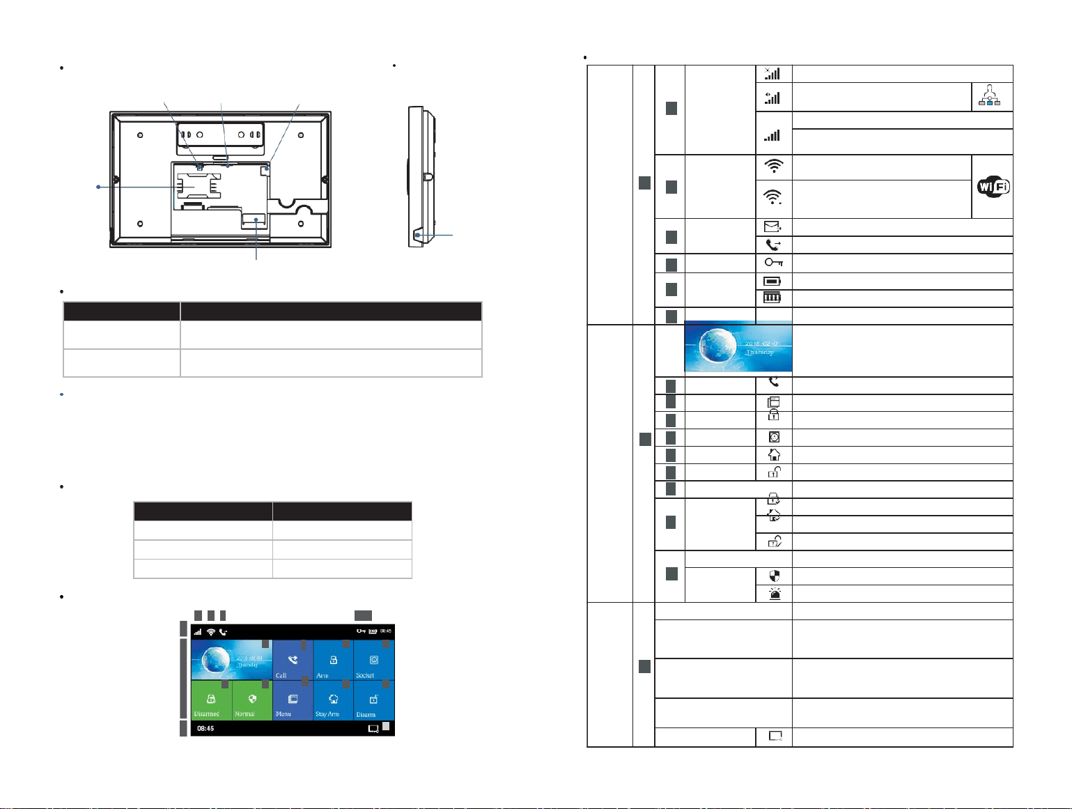
Back
Power
On/Off
5V USB
Wired Siren Jack
Side View
Main interface function and button description
SIM
Card Slot
Power On/Off
Wired Defense Zone Socket
Mic
Function
Method
Power On
Push this button, it will show “welcome”means power
on successfully
Power Off
Push this button for 3 seconds till the screen become black,
means power off successfully
SOS Button
Push this button when emergency, it will cause the strobe alarm locally, then
send the SMS alarm to the mobile defaulted, dial the mobile defaulted, push
the alarm to the mobile app and send the message to the networking alarm
center etc.
SOS button backlight
Back ground light
Status
Circulate twinkle
Alarm
Breathing twinkle
Alarm
Normally on
Disarm
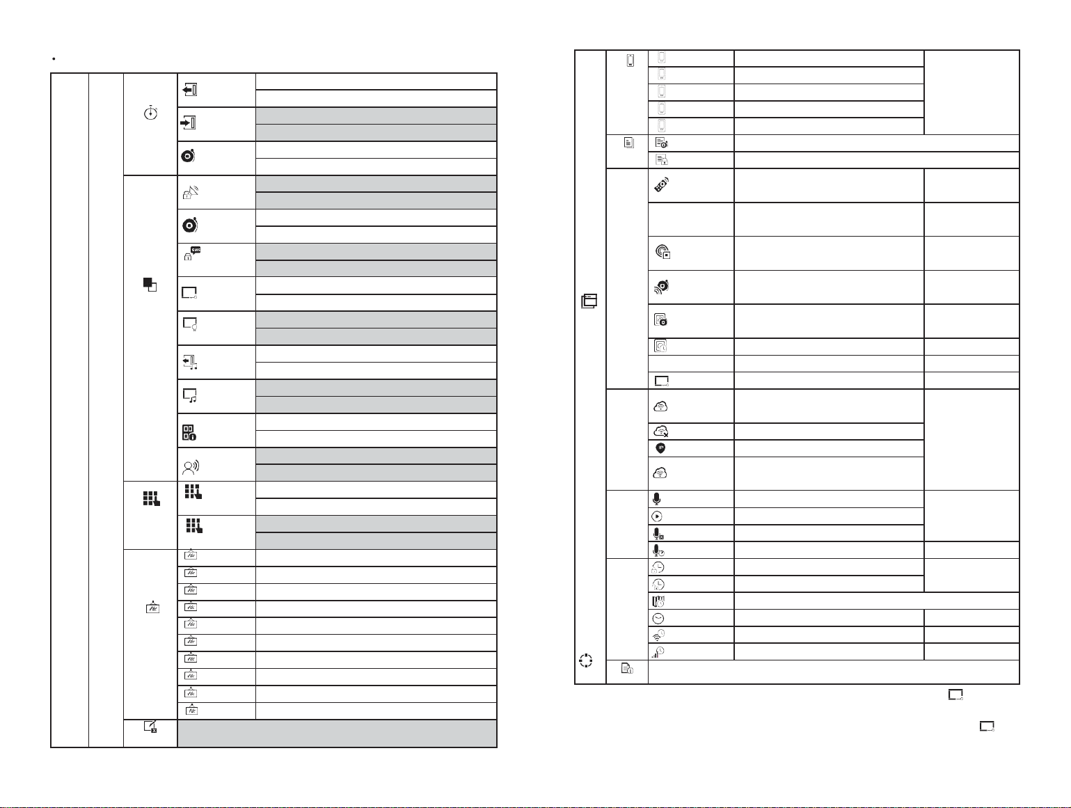
Navigating Menus
4 5 6 7 8 9
1
2
3
19
15
14
18
17
13
12
10
11
16
4
5
Top status bar
1
4
GSM
Status
indication
No SIM card or wrong inserting
GPRS networking status indication
GSM networking strength indication
No networking if gray color, 1~5 means the
strength level
5
WIFI
wireless
1~4 means the wifi strength level Gray
color means no wifi
Devicealreadyconnectedwiththecloud,
White dot at the right bottom corner
means the binding mobile is online
6
GSM
assign status
SMS sending
Telephone/mobile dialing
7
Keyboard Lock
Keyboard locked status,5seconds countdown
before locked
8
Power status
Main power supply
Spare power supply,0~3 shows the power capacity
9
Clock
00:04
Current time
Main status zone
2
Current date and week
11
Dial button
Push and dial the telephone number
16
Menu button
Push and enter into the menu setting
12
Arm button
Push and enter into the arm system
13
Socket button
Push and control the intelligent socket
17
stayArm button
Push and enter into stay arm
18
Disarm button
Push and enter into disarm
14
Arm/Disarm Log button
Push and searching the arm/disarm history
18
Arm/Disarm
status
Arm status
Stay arm status
Disarm status
15
Alarm Log
Push can searching the alarm history
Alarm
status
No alarm
Alarmstatus,willshowthezonenumberifthezonealarm
Bottom status bar
3
00
:
04
Current time
“Please exit”
Countdown bar
Exit the delay status
Enterintothe countdownstatus when armfinished
Willget to : get intowhen thecountdownfinished
“Please disarm”
Countdown bar
Enter into the delay status
Needto be thecountdown status when getto the arm
status,if no disarm, devicewill be triggered andalarm
“Synchronizing”
Countdown bar
Learning accessory state
Please trigger the parts before count down
Screen close button
Push and enter into black screen
Menu Structure
Main menu
System Setting
Delay
Setting
Exit Delay
Settheexitdelayvalue,pleaserefertothedailyoperationwords
Unit:seconds;scope:0~65535; default:40 seconds
Enter Delay
Set the enter delay value, please refer to the daily operation words
Unit:seconds;scope;0~65535; default: 30 second
Siren Duration
Set the siren duration time while alarming
Unit:minutes;scope:0~65535;default:3 minutes
Function
Setting
Arm Beep
Set the arm beep for external siren while arm/disarm
scope:on/off, default:off
Alarm Beep
Set the siren notice for internal/external siren while arm/disarm
scope:on/off, default:off
Arm/Disarm SMS
SMS notice while setting the Arm/disarm
scope:yes/no, default:no
KeypadLock
Keypad locked setting
scope:yes/no, default:no
Keyboard Backlight
Keyboard backlight setting
scope:on/off, default:off
Keypad Tone
Keypad Tone setting
scope:on/off, default:off
Delay Tick
Delay Tick notice while in/out setting
scope:on/off, default:on
Openning
Alert
Alert displays when ARMwith thedoor/window open
Option: ON or OFF; Default: ON)
Voice
Prompts
Voice prompts for keypad operation
Option: ON or OFF; Default: ON)
Password
Setting
System Password
System password setting
Scope:0000~9999;scope:6666
User Password
User password setting
Scope:0000~9999;default:1234
Language
Setting
Greek
Panel in Greek language
简体中文
Host Language: Simplified Chinese
English
Host Language: English
Deutsch
Host Language: Deutsch
РУССКИЙ
Host Language: Russian
Español
Host Language: Spanish
Polski
Host Language: Polish
Italiano
Host Language: Italian
Français
Host Language:French
Português
Host Language: Portuguese
Initialization
System Initialization, Function & describe as: System Initialization
Mainmen
Phone
Management
1st Phone
Group1alarmphonenumber&dialSwitch,SMSswitch
Seeas:
Phone Number
setting
2st Phone
Group2alarmphonenumber&dialSwitch,SMSswitch
3st Phone
Group3alarmphonenumber&dialSwitch,SMSswitch
4st Phone
Group4alarmphonenumber&dialSwitch,SMSswitch
5st Phone
Group5alarmphonenumber&dialSwitch,SMSswitch
Log
Searching
Alarm Log
Alarm log & Event record
Arm Log
Alarm/disarm log searching
Accessories
Remote
Controller
Add/delete remote controller
See as:
Remote controller
add/ delete
Detectors
Add/delete wireless detectors
See as:
Wireless detector
add/ delete
RFID
Add/delete RFID cards
See as:
RFIDcard add/delete
Siren Learn
External wireless siren pairing
See as:
External Wireless
Siren matching
Alarm Socket
Alarm linkage intelligent socket Airlink
See as
Wireless Alarm
Linkage
Socket Timer
Intelligent socket timer on/off setting
SeeIntelligentHome
1
Reader
Readthedatacodesentbyterminalaccessories
See
WiredDefenseZone
Alarm information for configuring wireddefense zones
See
Wi-Fi
Setting
Airlink
Host gets into WIFI wireless networking airlink
status
(
need to match mobile APP)
See as
Mobile APP with the
host airlink & unbind
Unbind
Unbind the mobile app with the host
MAC/IP
Get the Wi-Fi MAC&IP address
Hotspot
Configuration
Host gets into WIFI wireless network airlink
status
(
need to match mobile APP)
Record
Record/Playback
Record and playback
See as:
Record
management
Play
Play the current record
Delete
Delete the current record
Duration
Set record duration
scope
:
1~20 second
;
Default
:
20
Timer
Arm Timer
Arm timer time & on/off setting
See as:
Arm / disarm Timer
Disarm Timer
Disarm timer time & on/off setting
Zone&Sync
Setthe time difference between the localtime with the Greenwichtime
Date & Time
Host time manual setting
Wi-Fi Sync
Set if the time sync with the Wi-Fi
Scope: on/off; default: on
2G/3G Sync
Set if the time sync with the 2G/3G network
Scope: on/off; default: on
Version
Search the Wi-Fi firmware、MAC address、2G/3G firmware、2G/3G module IMEI number、
host firmware、host serial number
Note: 1.Keyboard lock open: at the main interface, no pushing within 30 seconds or push directly,
host will enter locked status. After locked, the user must enter a password to unlock before he can operate
the host.
2.keyboard background light closed: at the main interface, no pushing within 30 seconds or push directly,
host backgroundlight will be closed to save the power.
After selecting one language, the operation notice, display, SMS message will switch to the same language,
6
host will restart while finished.
7

!
1
24h
Initial Use
Getting started
Insert Card:insert a standard micro SIM card into the card slot as
illustrated below
Power On: plug in the power adapter through the USB 5V interface.
Host On: when the host is off, switch to ON and‘Welcome’ displays.
The host is on.
Host Off: when the host is on, switch to OFF and black screen displays.
The host is off.
System initialization
Main menu-System Setting-Initialization. All parameters, languages and
time zones set by users will be back to factory default setting, all remote
controls, detectors, RFID tags and records will be deleted, after initialization.
Networking IP deleted, the host is in GPRS offline statue. You’ll
need to send SMS to reset IP for the host to go back online.
Caution! only advised to do this when you forget operation
password, host malfunction, parameters setting mistakes, unidentified
detectors, remote controls or RFID tags learned. Initialization doesn’t
work under Keypad Lock.
Menu Operation
Adding/Deleting Remote Controller
P
u
sh: Ma
in
m
enu
Parts
R
em
ot
e
co
n
tro
lle
r,
en
t
e
r th
e in
t
e
rfac
e
for r
em
ot
e
controller setting.
Push or for page down,it will show all the Synchronized remote
controller
Adding a new remote controller
Press to add remote, 20-second countdown starts. Press any of the 4
buttons on the remote control so that it sends wireless signal to the host.
When ‘Learning OK’ displays, the remote is added successfully.
When ‘Device code has been learned’ displays, it means the remote
control was added already or it has the same wireless code as the other
wireless detector added. Please change to a new remote.
Deleting a remote controller
Press on the list of remotes to delete the remote,
Press to delete all remotes.
Match code with/delete wireless detectors
Press:
Main
menu
Parts
Detector,enter into
the detector setting
interface. Press or page down
,
it will list all the Synced wireless
detectors.
Sync the new wireless detectors
Press ,host get into the”SetName/Mode/Number”interface.
This product is designed with capacity touchscreen, utilizing current sensing
of human body to function.
Press
Press
,choose the name of the zone for the none Sync wireless detectors.
,choose the type of the zone for the none Sync wireless detectors.
For features not listed in this chapter, refer to the descriptions in the diagram
above.
Function described in this part: include the phone number setting, remote
controller add/delete, wireless detector add/delete and the external
wireless siren matching can be set by mobile app.(only with )
Adding Alarm Phone Number
The host can be set to communicate with up to 5 phone numbers,
dialing and SMS feature of which can be enabled/disabled separately. To
set #1 phone number, for instance:
1. K
eyp
ad operation: Main
Menu
Phone
1st Phone, pr
ess
to ent
er
setting interface. Youcan input the alarm phone number (max.18 digits).
2. Move to and press
to set it on/off. When you set it on, the host will call this phone number
when alarm happens.
3. Move to and press
to set it on/off. When you set it on, the host will send SMS to this phone
number when alarm happens.
4. Press to confirm Setting.
8
Choose”Stay Arm Active”,after the arm or stay arm setting, the detectors in
this zone will alarm while be triggered. Front Door 、 Window 、 Balcony 、
Perimeter use this kind of detectors.
Choose“ Out Arm Active”, after the stay arm setting, the detectors in this
zones will not alarm while be triggered. Living Room 、 Bedroom and other
internal place use this kind of detectors.
Choose ”24 Hours Active”, it will alarm while be triggered anytime, SOS
Panic、Smoke/Fire、Gas、CO、water Leakage use this kind of detectors.
Choose”Close”,it will not alarm while triggered.
For wireless doorbell, please choose”Doorbell”, It will note “dingdong”
anytime while be triggered.
24 Hours Silent: alarm sent when detectors triggered, siren muted,
recommended for SOS(PANIC),smoke,gas,CO,water leakage detectors,etc.
Stay Arm Active without Delay: when panel is armed or star armed, alarm
sent when detector is trigged without delay, recommended for door,wondows,
balcony,perimeter detectors.
Out Arm Active without Delay: when panel is stay armed,alarm won't be sent
when detector is trigged,recommended for living room, bedroomdetectors.
9

!
A
24h
!
1
Press enter & edit the zone code of the none Sync wireless detectors,
please do not be repeated with the code of the other zones.
Press
,host will show”Synchronizing”, and will get into the dialogue
Go to M
enu
Parts
R
F
ID
D
ele
t
e
to d
ele
t
e
th
e
R
F
ID
T
ag sp
e
c
i
f
ie
d b
y
box for 20 seconds cut down of the wireless detectors.
Trigger the wireless detectors and send signals to the host.
When host shows”Learning OK”, means the detectors Sync successfully, it
will list all the name of the detectors, type, code and address code.
If host shows”Device code has been learned”,means the detectors have
been learned or repeated with the code of the other learned remote
controller, need to be changed.
Delete
Press the listed detectors ,delete the chosen detectors.
Press ,delete all the detectors.
Setting Name/Type of Wired Defense Zone
The host supports up to 4 wired defense zones, name and type of which can
be set separately.
Zone number for wired defense zones are not changeable and within
100-103
Setting wired zone #1 .for example:
M
a
in
M
enu
Parts
W
i
r
e
d
Z
o
ne
, w
i
r
e
d zo
ne
1,
en
t
e
r s
e
tt
in
g。
Press to set name.
Press to set type.
Stay Arm Active usually assigned to sensors on entry and exit doors, exterior
doors and windows, perimeter. Active when armed in AWAY or HOME mode.
We recommend to set Door/Window Sensor to Stay Arm Active.
Out Arm Active usually assigned to a interior area (i.e.: foyer, lobby,or room).
Bypassed automatically when armed in STAY mode. We recommend to set PIR
Motion Detector to Out Arm Active.
24 Hours Active usually assigned to a zone containing an Emergency Button,
Smoke Sensor, CO, Water Leakage and Gas Sensors.
To used as doorbell, select Doorbell.
How to Pair a New Wireless Siren by Touchscreen
Go to M
enu
Parts
Si
r
en Le
ar
n
Press and hold the SET button of the siren until you hear two beeps, then
the siren goes into the paring mode and the light ring blinks quickly.
How to Pair a New RFID Tag by Touchscreen
Go to M
enu
Parts
R
F
ID
Add a
n
d
en
t
e
r
Synchronizing is shown, the hub goes into the paring mode and count down
the pairing time remained .
Tap the RFID Tag on the panel:
As the serial number of RFID Tag is added to the hub, Leaning OK will be
shown.
serial number .
Go to M
enu
Parts
R
F
ID
D
ele
t
e
A
ll
to d
ele
t
e
a
ll
th
e
R
F
ID
T
ags.
Tap on the touchscreen within 6 seconds. The hub shows Learn Signal Sent
and sends a transmission signal to the siren.
The siren gives four beeps of successful indication.
If you want to unbind the wireless siren with the hub, press and hold
the SET button of the siren until you hear three beeps.
How to Pair a New Wireless Socket by Touchscreen
Go to M
enu
Parts
A
l
ar
m S
ock
e
t
Press and hold the button of the switch until it lights up, then the switch goes
into the paring mode.
Tap on and off on the touchscreen . The hub shows and sends
the on and off transmission signals to the switch.
The siren gives three flashes of successful indication.
When a sound alarm occurs,the alarm wireless switch opens until
the system is disarmed or alarm sounder timeout occurs.
If you want to unbind the alarm wireless switch with the hub, press and
hold the button of the switch for about 10 seconds until light is off .
Smart home appliance
Full sockets
Interface press:press Socket,enter into the intelligent socket controlling interface.
Syncing
The syncing method between the host with the socket, please refer to
the”alarm linkage intelligent socket syncing”one host can sync with several
socket. press"On” or" Off” host will have the on/off signal to control the
wireless socket.
socket which synced the host succeed, can used the host or the mobile
app to control on/off, or can do timer control for the socket.
Socket Timer
Host can
set
several groups timer to open
/
close the intelligent socket
. C
an set
the socket number
,
time
,
time on
/
off etc
.
in each group
.
Pr
e
ss: Ma
in
m
enu
Parts
S
ock
e
t
Time
r,
en
t
e
r th
e in
t
elli
g
en
t sock
e
t t
ime
r
interface
.
Add the timer
Press , enter into the socket timer setting interface.
Press or + in - ,set the socketnumber.
Press or + in - ,adjust the timertime.
Press the week item in ,set the day of the week.
The hub will show Device code has been learned if serial number of RFID
Taghas beenlearned.
10
Press choose timer on oroff.
Press , finishthe setting.
11
!

Edit
Press the serial number front of the Timer, can edit the relevant timer, same as
the above.
Wireless alarm linkage
Sync with alarm linkage intelligent socket
Pr
e
ss:
M
a
in
m
enu
Parts
a
l
ar
m lin
kag
e in
t
elli
g
en
t A
l
ar
m S
ock
e
t,a
n
d
en
t
e
r
Delete
Press behind of the timer list, delete the relevant timer.
Press delete all theTimer.
Voice Recording
Alarm Recording
You can record up to 20s voice, the host will call pre-set phone numbers and
play the voice.
M
a
in
M
enu
V
o
i
c
e
R
e
cord
in
g
R
e
cord a
n
d P
l
a
y
.
The host displays “Busy, please wait”
When it displays “Recording”, the countdown starts.
Speak to the host, make sure the voice record is simple and precise, This is
address, intrusion detected’
When finished,“Voice record playing” displays, and you’ll hear the playback.
Click to save, it prompts “Saving, please wait”
When "Operation succeed" displays, the recording is done.
Timed Arm/Disarm
You can set auto arm/disarm based on your routine to avoid duplicated
operation in everyday life or not to forget arm/disarm.
Timed Arm
M
a
in
M
enu
C
l
ock
Time
d Ar
m
Click + and - to set arm time (hour,minute)
Click to select"ON".
Click to confirm.
Timed Disarm
M
a
in
M
enu
C
l
ock
Time
d d
i
sar
m
.
Click+ and - tosetarm time (hour,minute)
Click to select"ON".
Click to confirm.
Mobile APP
Refer to Smart Life APP Quick Use Guide.
12 13
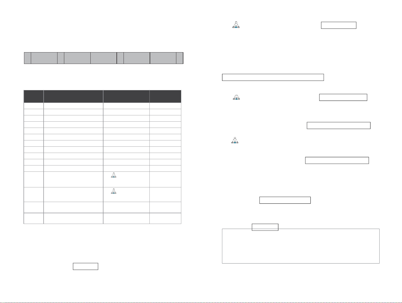
REMOTE SMS
Set Parameters by SMS
User only need to edit the SMS as below format, and send to the host SIM card
number to finish thesetting.
*
System
password
*
Address
setting
Content
setting
*
Address
setting
Content
setting
*
One SMS can be include one or several address and content, but need to be
separated by *, the head and the end must be *, each address should be 2
digits, otherwise it may have the unexpected result, each SMS must be less
than 160 bytes, we suggest to finish all the contents in one SMS.
2
、
Alarm phone number setting format: xxxxxxxxxxx,A,B
Such as: xxxxxxxxxxx is the phone number(no more than 18 digits),A: alarm
voice dial switch(1-on,0-off),B: SMS alarm switch(1-on,0-off).
For Example:
Set 2 alarm phone number, the one 13912345678used to receive the voice
dialing and SMS,the one 075581234567only used to receive the voice dialing,
then the SMS content should be:
*6666*5113912345678,1,1*52075581234567,1,0*
3
、
IP address setting format should be: aaa,bbb,ccc,ddd,xxxxx
Such as: aaa,bbb,ccc,ddd is the IP address,xxxxx is the port number,use the
comma to separate for each address.
For example:
Set the GPRS network sever IP address is 116.62.42.223,port number is 2001,
then the SMS content setting should be: *6666*90116,62,42,223,2001*
4 、 Set the local GSM operator GPRS access point APN
For example:
Local GSM operator GPRS access point APN is internet.beeline.kz,then
the SMS content setting should be: *6666*92internet.beeline.kz*.
Set Control Panel’s Name by SMS
Set one name to the host, used for the prefix for the alarm SMS, so to
distinguish the position for each alarm host.
SMS setting format 1234 is the user password, @is the
commend words, “XX estate a building” is the content name (no more
than 40 digits).
Searching system setting:
Setting comment( allthe example used the default system
password:6666):
1、Parameter initialization:keep the learned remote controller, wireless
detectors
and RFID cards, others recovery to factory setting.
Set the SMS content as: *6666*43* .
SMS format:
, host echo:
14
15
ENGINEER PASSWORD: Engineer password
USER PASSWORD: GSM field strength value(0 or 99means the signal unusual)
WIFI RSSI: WIFI field strength value
Host serial number
Host language
YSTEM set:
SN:
LANGUAGE:
*6666*62*
Address
Function
Content & Scope
Factory Setting
35
Redial times while dial failure
1~255 Times
1 Time
36
bell ring timeswhileauto receiving
1~255 Times
1time
(
in future
)
38
User name password correct
0000~9999must be 4 digits
1234
39
System password correct
0000~9999must be 4 digits
6666
43
Parameter initialization
See note 1
51
alarm phone 1st setting
See note 2
Closed
52
alarm phone 2nd setting
See note 2
Closed
53
alarm phone 3rd setting
See note 2
Closed
54
alarm phone 4th setting
See note 2
Closed
55
alarm phone 5th setting
See note 2
Closed
62
Search the GSM field strength
Empty
90
Set the GPRS sever IP address
this setting only be
validwhiletheGPRS online,
see note 3
Empty
92
Set the GPRS APN
this setting only be
validwhiletheGPRS online,
see note 4
CMNET
93
Set domain name of the
network time sever
us.ntp.org.cn
94
Set the time difference with
the standard Greenwich time
+8
!
*6666*33*
1
3
PHONE set:
1: 1 alarm phone number, voice switch, SMS switch, general switch
2: 2 alarm phone number, voice switch, SMS switch, general switch
3: 3 alarm phone number voice switch SMS switch general switch
4: 4 alarm phone number voice switch SMS switch general switch
5: 5 alarm phone number voice switch SMS switch general switch
REDIAL COUNTER: voice alarm redial counters
delay entering(unit: second)
delay quit(unit: second)
alarming time(unit: minutes)
DELAY set:
ENTRY:
EXIT:
SIREN:
arm/disarm Beep switch(1:on, 0:off)
alarm beep switch(1:on, 0:off)
arm/disarm SMS switch(1:on, 0:off)
SWITCH set:
ARM/DISARM BEEP:
ALARM BEEP:
ARM/DISARM SMS:
DETECTOR learned:
REMOTE:
DETECTOR:
RFID:
learned remote controller quantities
learned detectors quantities
learned RFID card quantities
Searching system 2
SMS format: *6666*90* , host echo:
PHONE FUNCTION
Push in the main interface, and enter the phone number dialing interface.
Push
2
to look over the dialed phone number.
In any of the following states, phone call operation will be forbidden: GSM
network abnormal, arm/disarm, phone alarm being in progress.
Alarm phone number searching setting
SMS format: *6666*51* ,host echo:
Delay searching setting
SMS
format
:
, host echo:
Searching switch setting
SMS format: *6666*46* ,host echo:
Learned remote controller & detector quantities
SMS format: *6666*26* ,host echo:
16
17
Name of the GPRS access point
GPRS network IP sever & client number
Network time sever domain name
GMT standard time
Sever
SYSTEM set2:
APN:
GPRS IP:
NTP:
TIME ZONE:
SERVER
:
!
!
!
User Daily Operation
Users can operate the alarm host in any ways as below:
On-site Remote controller, keyboards , RFID cards .
Remote SMS
Mobile phone APP
GPRS alarm center
Out Arm
By remote control: press 【 】 key to trigger “Out Arm”.
By keyboard: In Main Interface, press to trigger Out Arm.
By RFID tag: In disarm mode, put the RFID card close to the sensitive
area on bottom right corner of the alarm host.
By remote SMS: Send SMS message 1234#1 (1234 is user password),
the alarm
host will send “System Armed!” SMS to mobile phone to confirm.
By APP: In Main Menu, select “icon, After around 3 seconds, operation
for “Out Arm” is completed, the App status icon updated to Out Arm.
The alarm host reminder: A reminding voice “System armed” will be
heard, the main Interface displays “Armed” and “Please exit”, and an
exit time progress bar appears. The user should leave the alarm zone
before exit time. If Arm/Disarm SMS switch 【 】 is on, the preset
phone will receive SMS of “System Armed!”.
In Out Arm mode, all defense zones are on alert statues. If there is
any defense zone being triggered, the alarm host will generate sound
and light alarm. Meanwhile, alarm host will send alarm SMS and make
calling to preset phone number, and push alarm information to
APP/GPRS alarm center. If alarm host has been learned alarming
leakage smart plug, the plug will switch on when alarming.
Stay Arm
By remote control: press 【 】 key to trigger “StayArm”.
By keyboard: In Main Interface, press to trigger Stay Arm.
By remote SMS: Send SMS message 1234#3 (1234 is user password), the
alarm host will send“System Stay Armed!” SMS to mobile phone to confirm.
By APP: In Main Menu, select “ Stay Arm” icon, after around 3 seconds, the
operate for “Out Arm” is completed.
The alarm host reminder: A reminding voice “System armed” will be
heard, the Main Interface displays “Stay Armed”. If Arm/Disarm SMS switch
【 】
is on, the preset phone will receive SMS “System Stay Armed! “.
18
In Stay Arm mode, only valid Stay Arm defense zones are on alert
status. If any defense zones is been triggered, the alarm host will
generate sound alarm, Meanwhile, alarm host send alarm SMS and make
calling to preset phone number, and push alarm information to
APP/GPRS alarm center. If alarm host learned alarming. leakage smart
plug, the plug will switch on when alarming.
Disarm
By remote control: press 【 】 button to trigger “Disarm”.
By keyboard: press on main interface .
By RFID tag: in out arm/stay arm mode, put the RFID card close to the sensitive
area on bottom right corner of the alarm host. By SMS: Send SMS message
1234#2 (1234 is user password), the alarm host will send“System Disarmed!”
SMS to mobile phone to confirm.
By APP: In Main Menu, select “ Disarm” icon, after around 3 seconds, the
operate for “Out Arm” is completed.
The alarm host reminder: A reminding voice “System Disarmed” will be heard,
the Main Interface displays “Disarmed”. If Arm/Disarm SMS switch is on,the
preset phone will receive SMS “System Disarmed!”.
In Disarm mode, all alarm procedure will be terminated, If Arm/Disarm
SMS switch is on , the preset phone will receive SMS “System Stay
Armed! “. If alarm host learned alarming leakage smart plug, the plug will
switch off.
SOS
By remote control: press【SOS】button on the remote control.
By keyboard: Press 【SOS】 on the main interface of the alarm host.
By APP: Select”SOS”icon in the main menu.
The alarm host reminder: The Main Interface displays “Help”. The alarm
host will generate a sound alarm, and send alarm SMS or make calling to
the preset phone numbers , simultaneously send the alarm message to
mobile phone APP or GPRS alarm center.
Confirm the operation result by SMS
<The alarm host name>:
The result of remote operation
19
ALARM & REMOTE MONITORING
The host supports multiple types of alarm. When alarm occurs, it sends
alarm messages containing the detector name and number to the user's
mobile phone, pushes alarm information to the mobile phone APP, and
sends alarm information to the handset monitoring center. At the same
time, it dials the user's telephone, and the user can conduct on-site
monitoring and remote control after the connection.
The host also supports the following alarm classes
Main power failure (the alarm is effective after the main power failure
lasts for 5 seconds)
Anti-prying alarm (alarm after separation of main engine wall mounting
bracket and main engine)
Spare battery power shortage (The alarm is valid when the spare battery
voltage is less than 3.45V and lasts for 10 seconds under the condition
of main power failure.)
Main power recovery.
SMS Alarm
Alarm occurred, host will send SMS manger to the preset phone
numbers,should
Mobile app alarm recieving procedure
When alarm occurs, panel sends push notification to your mobile phone. Users
can check the alarm type in the APP main menu. Tap on 'Alarm Info' to check
all records of panel operations and alarm logs.
Networking Alarm Receiving Procedure
When alarm occurs, host will send the alarm message to the network
monitoring center via the GPRS. The emergency response can be handled
quickly after the central police have responded to the alarm.
This function will be valid only after the host has been opened with the
user network alarm function and service.)
The IP address must be set up by using SMS, and this function will be effective.
APN must also be set in foreign or other areas. As for the method of these two settings,
please see SMS message setting parameters).
<Host Name>:
Current alarm!
Defense Zone:xx
Auto Dial Number Setting
When alarm occurs, host will dial the preset phone numbers. (dial switch
should be opened), after user answered, host will displays the current
alarm type first, if there is a default recording, it will have voice notice
"Press 1 is arm, Press 2 is disarm, Press 3 to monitor, Press 4 to talk". If
user finds the misinformation, press 2 to disarm and end the alarm
progress. Users can also press 3 to close the scene alarm. Just hang up
the phone without monitor.
If the user fails to answer or dial, the host will continue to dial the preset
phone according to the preset number of dials until the user receives the
call.
Preset Telephone Remote Calls Host
When several sets of telephone numbers preset by the host actively call
the alarm host, the host will automatically connect, after the call is
connected, the host can monitor the on-site scene or control the host
according to voice prompts.
20
21
!

Technical Parameters
-Input Voltage: DC5V (Micro USB Standard Interface Power Supply)
-Working Current: <140mA when the screen is off, <280mA standby
current when the screen is on
-Standby Current: 0uA
-Siren Output: <560mA
-Wireless Frequency: 315/433/868/915Mhz
-Wireless Coding: eV1527
-GSM System: 850/900/1800/1900MHz
-WIFI System: IEEE802.11b/g/n wireless standard
-Spare Battery: 3.7V/1000mAh lithium battery
-Working Temperature: -10 ~ 55 ℃
-Relative Humidity: < 80% (no condensation)
-Product Size: 160*98*19MM (length x height x thickness)
PACKING LIST
-1 host with the spare battery
-Micro USB 5V/1000mA standard power supply
-Others as the customer OEM requirement.
22 23