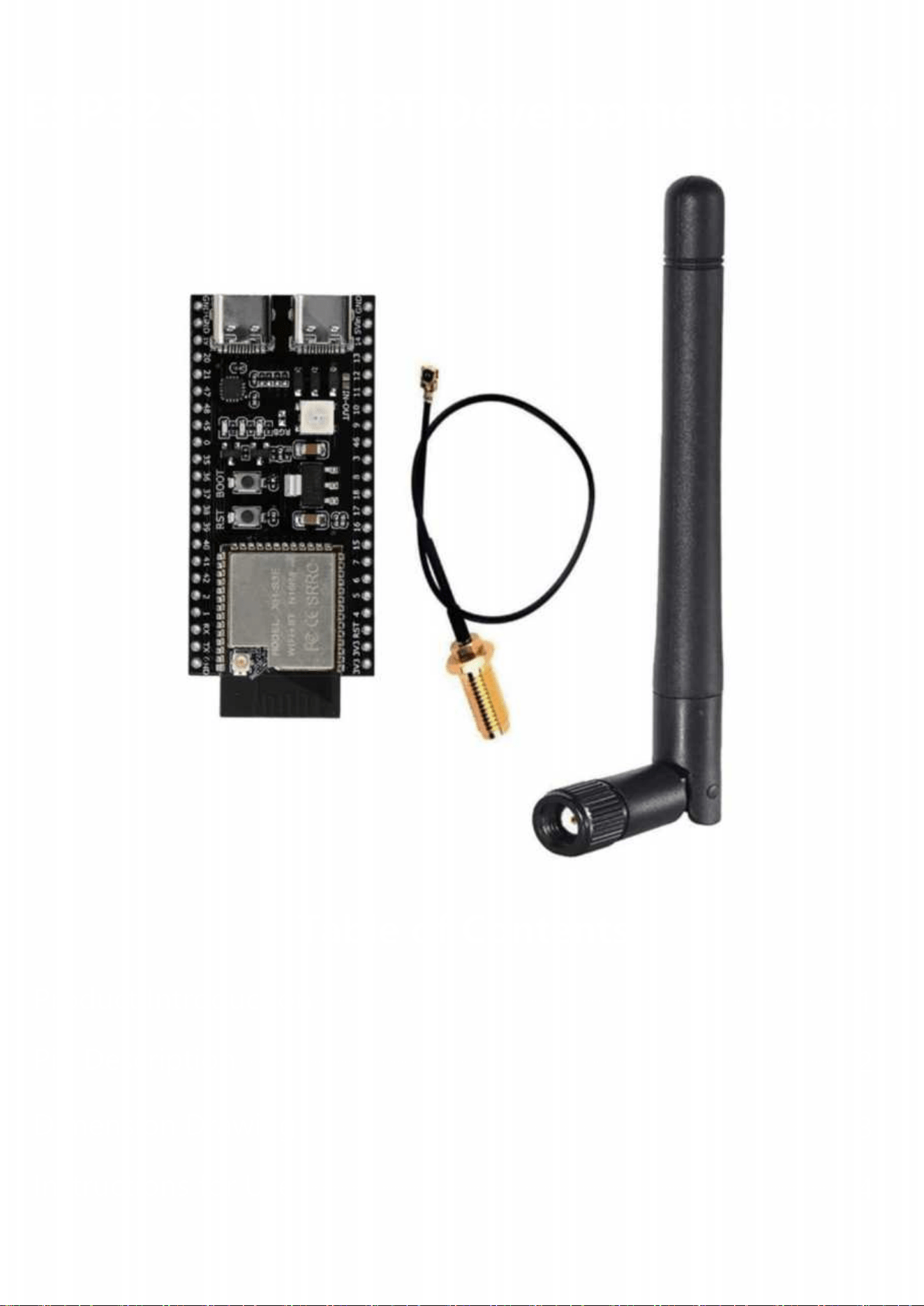
ESP32 S3 WiFi BT Development Board
Table of Contents
Product Introduction
1
Pin Description
2
Dimension Drawing
3
Instructions for Use
4

The ESP32-S3 is a low-power MCU system-on-chip (SoC) that
supports 2.4GHz Wi-Fi and low-power Bluetooth® LE wireless com-
munication. The chip integrates a high-performance Xtensa® 32-bit
LX7 dual-core processor, an ultra-low-power coprocessor, Wi-Fi
baseband, Bluetooth baseband, RF module, and peripherals.
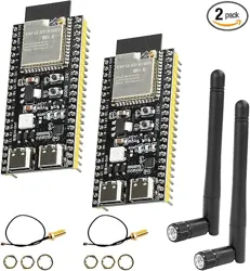
This product is a development board based on the
ESP32-S3-WROOM-1 module, featuring numerous I/O ports, with an
onboard WS2818 RGB connected to I/O port 48. It includes two
Type-C interfaces: one is directly usable with a COM label, while the
other USB port can be used via OTG or by holding down the BOOT
button during power-on to display the port normally and download
the program. The factory-default program automatically lights up the
RGB when connected to Wi-Fi and turns off when disconnected.RGB when connected to Wi-Fi and turns off when disconnected.
Specifications: N8R2, N16R8
Operating voltage: 3.3–5V
IO ports: 36 IO ports
Flash: N16R8 (16M), N8R2 (8M) (optional)
PSRAM: N16R8 (8M), N8R2 (2M) (Optional)
Product Introduction
Product specifications

2 I2C interfaces, 4 SPI interfaces
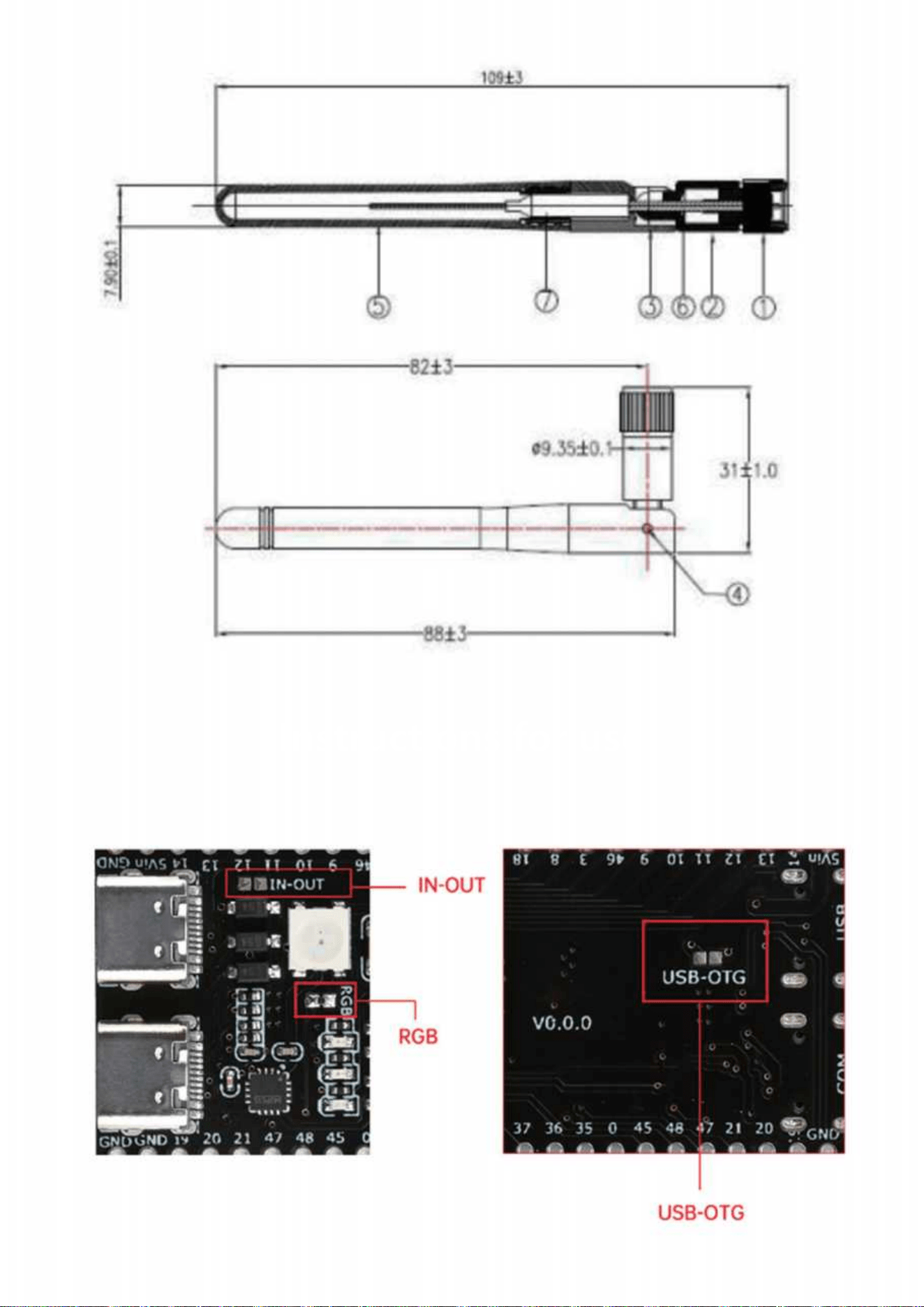
PCB board dimensions: 57mm x 28mm
2.4GHz rubber rod antenna:
Color: Black
Gain: 3dBi
Frequency band: 2400-2500MHz
Characteristic impedance (Ω): 50Characteristic impedance (Ω): 50
Gain (dBi): 2 ± 0.5
Output voltage standing wave ratio (VSWR): ≤1.92
Maximum power: 10W
Polarization: Vertical polarization
Directionality: Omnidirectional
Connection type: SMA
Total height of rubber rod antenna: 11cm Total height of rubber rod antenna: 11cm
IPX cable length: Approximately 15cm
Antenna housing material: TPEE
Operating temperature: -20°C to +70°C
Product list
1X development board
2X pin headers (un soldered pin headers/soldered pin headers availa-
ble)
1X antenna (without antenna/with antenna available)

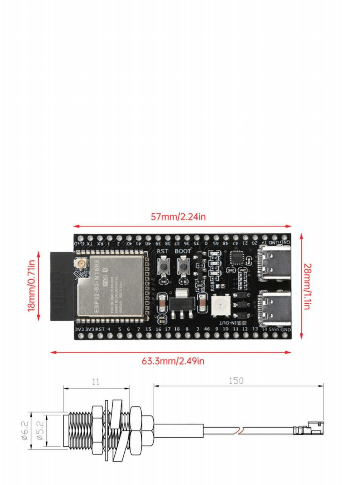
Product Pin Description
Note:
Be careful not to short-circuit the pins, as this may burn out the
module.
For detailed module parameters, please contact customer service to
obtain the module specifications.
ThisThis document represents the product knowledge and parameters at
the time of editing. Please note that any subsequent changes will not
be notified separately.
Product dimensions
Instructions for use
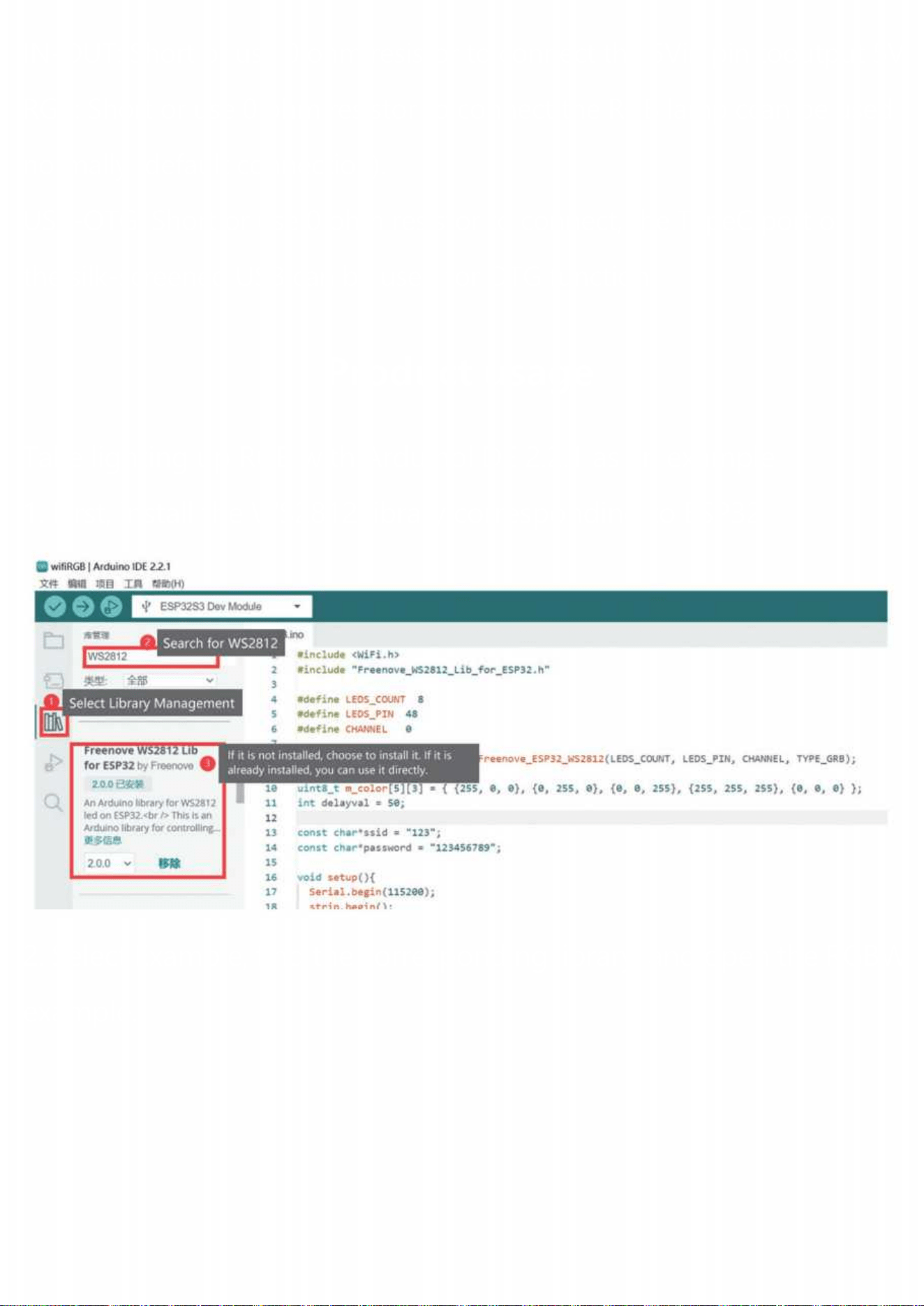
IN-OUT: Short or use 0 ohm resistor to connect the 5Vin pin tooutput 5V
RGB: Short or use 0 ohm resistor to connect the RGB lamp ccan be used
normally (default connection).
USB-OTG: Short or use 0 ohm resistor to connect, the TypeC port of
the silk-screened USB can be used for OTG function.
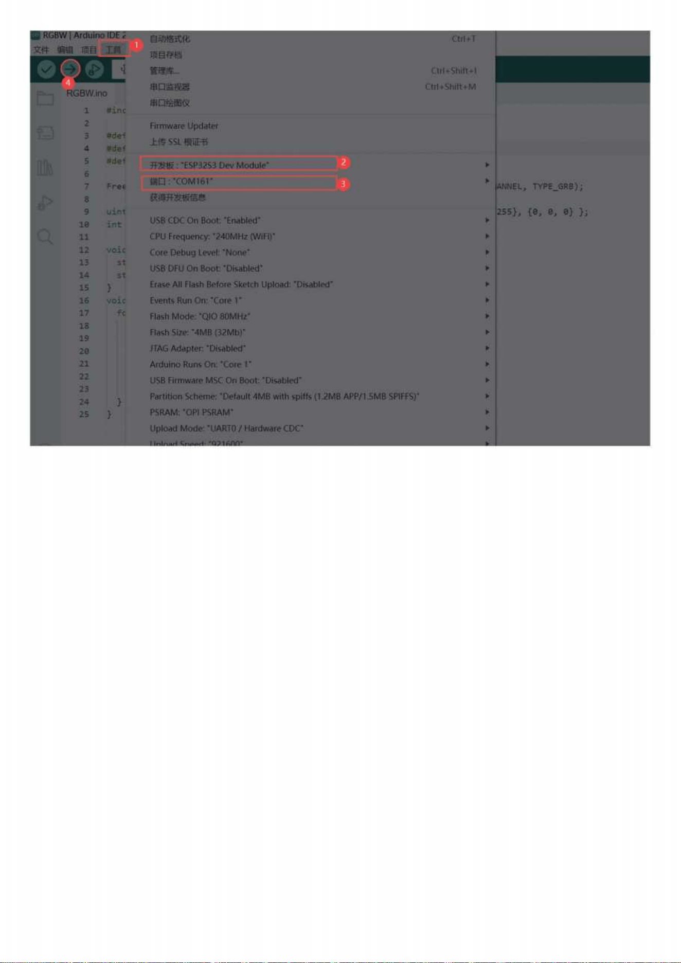
Take lighting up RGB with Arduinol DE 2.2.1 as an example
1. First, install the WS2812 library corresponding to ESP32
2. Select Example, find the corresponding library, and open the RGBW
example.
Product usage
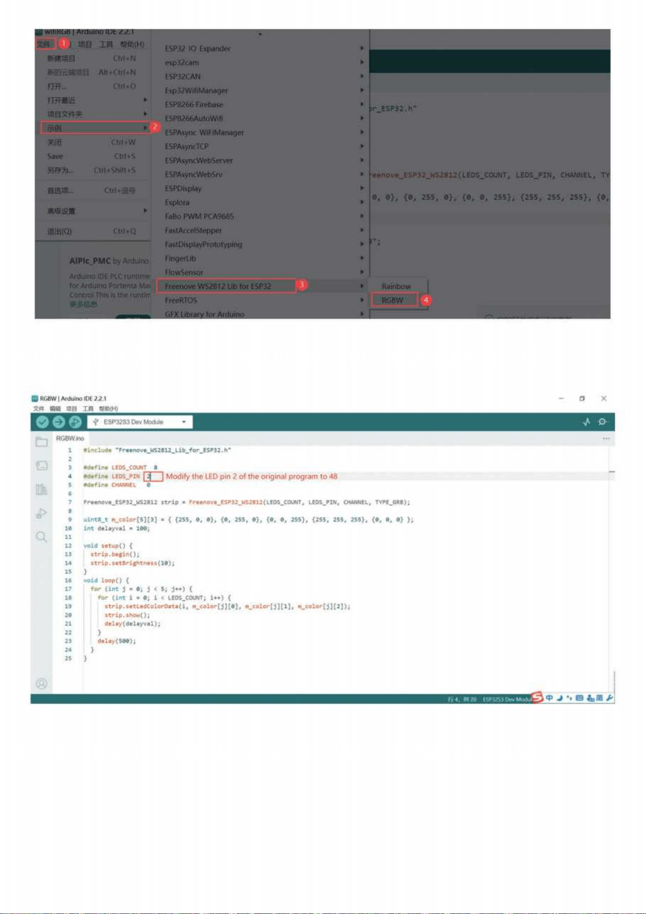
3. Change LEDS_PIN defined in line 4 of the program to 48.
4. Select the port and development version, then click “Upload.”