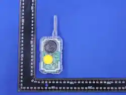
EZTalk 80
USER’S MANUAL
正面
背面
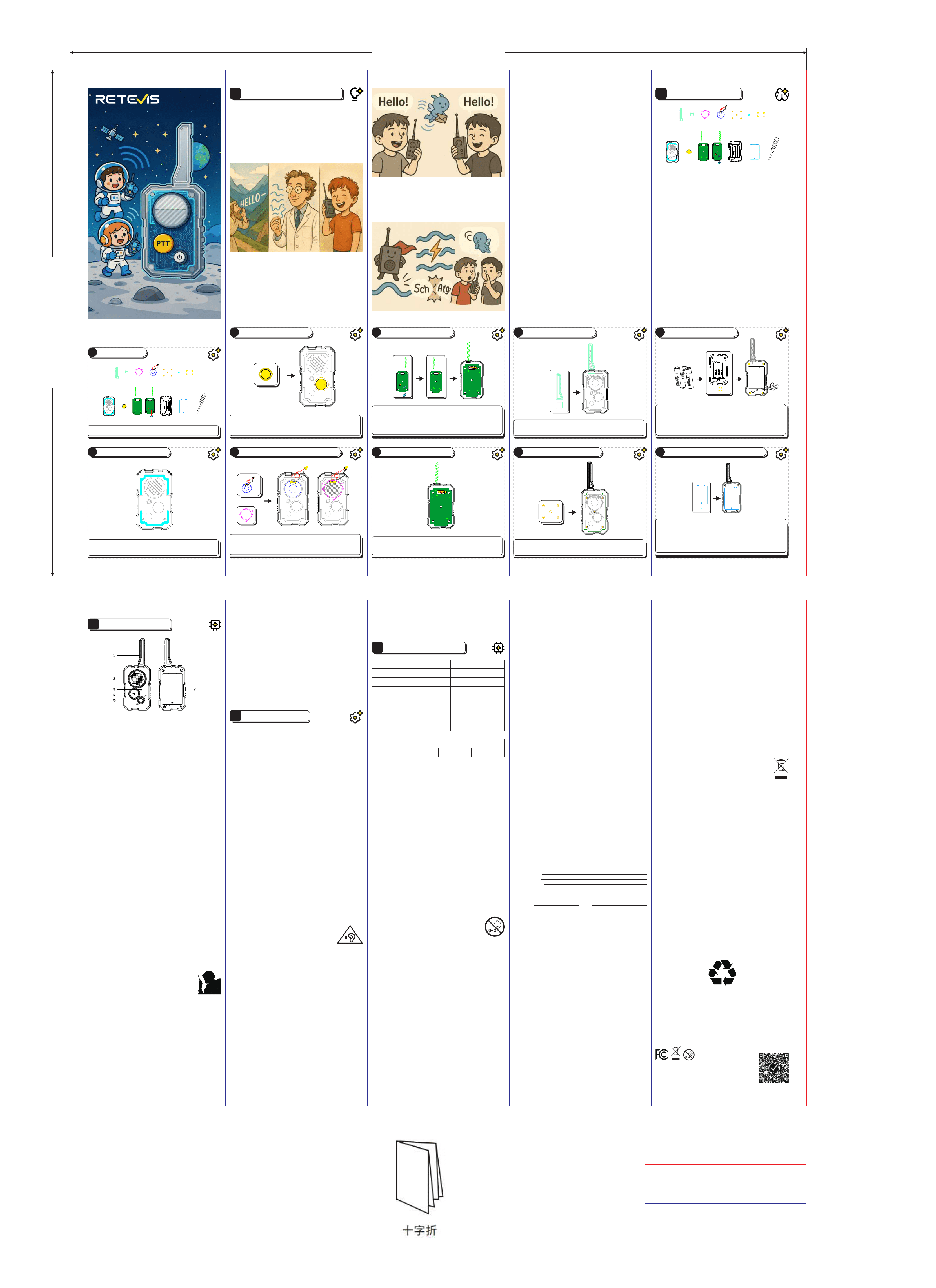
Assembly Oveiew (Order: Front cover → Back cover; Speaker →
Motherboard; Test before closing the case)
2
Place the Front Cover
Lay the front cover h at with the mesh side against the table, ready to
“welcome” the components.
1
Preparation
Lay out all pas a–m. Work with an adult for safety and extra fun.
3
Install the PTT Button
Inse the PTT button cap i from inside into the button slot. Make sure
the small hole is on the left and the big hole is on the right. Press it—if
it bounces back smoothly, it’s correct.
4
Install Speaker and Fixing Ring
Place the speaker d into the large round slot with wires facing upward
toward the antenna.Use the xing ring c to press the speaker down,
securing all four corners tightly.
5
Install Circuit Board
Gently place the circuit board j into the front cover with the spring
antenna facing up towards the antenna slot. Ensure the board edges t
inside the bracket.
Note: The small spring on top of the board is the antenna—carefully
guide it through the hole in the front cover.
6
Connect the Speaker
Pass the speaker’s red and black wires through the hole on the
motherboard.Then align the white plug at the top with the SPK socket
on the circuit board, keep it not skewed, and plug it in.
7
Place the Front Cover
Place antenna cover a into the long upper slot.
Secure with the U-shaped clip b until you hear a “click.”
8
Secure the Circuit Board
Use screws e to x the board on the posts (four corners + center).
Remember to tighten it.
10
Install Batteries & Battery Cove
Be extra careful here:
Ensure the power switch is at the top right (Power OFF).
Open the batte cover, inse 3 × AA batteries (check polarity marks,
do not reverse).
Close the batte cover and secure with screws f.
Note: Remove the batte if the device will not in use for a long time.
A Little Sto About Walkie-Talkies
Once upon a time, people could only send messages by writing letters or
shouting loudly. Then, scientists discovered an "invisible magic wave"—Radio
Waves! These waves could travel quickly through the air and car sound over
long distances.
In the 20th centu, people invented walkie-talkies. The earliest walkie-talkies
were huge, like a brick, and could only be used by the milita or police. As
technology improved, walkie-talkies became smaller and more advanced, and
soon ordina people could use them to chat with friends. Today, you can
even build your own walkie-talkie and use it to communicate with your
buddies! How cool is that?
How Do Walkie-Talkies Work?
A walkie-talkie is like a "magic bridge."
1. When you speak: Your voice is captured by a small microphone and turned
into an electrical signal.
2. Electrical signal transformation: This signal rides on an "invisible fast
train"—radio waves—that quickly travels through the air.
3. Your friend's walkie-talkie receives it: The other walkie-talkie acts like a
catcher, grabbing the incoming radio waves and turning them back into
sound.
4. And then you can chat!
Isn't it amazing? These invisible and untouchable “waves” can actually car
sound ying back and foh!
A Brief Guide to Walkie-Talkies
A
Interesting Trivia
A walkie-talkie is like a superhero's "instant megaphone”—no need for SIM
cards or internet!
Radio waves travel incredibly fast, almost as fast as light!
But here’s a little secret about walkie-talkies: Only one person can speak at a
time; the other must remain silent, or else their voices will clash.
may result in accidental contact of positive/negative poles).
5."Modication by feel" is prohibited: Do not replace the original kit pas
(such as mismatched batteries, wires, etc.), or subtract/add components
(such as leaving out insulating pads). This may damage circuit stability and
cause overheating or leakage risks.
6.Guide children to recognize positive/negative poles (“+/-” signs on both
circuit board and batte). Wrong installation can burn the circuit board.
7.Remind children not to put small pas in their mouth throughout assembly:
especially screws and small buttons. If the child tends to bite objects, they
may wear child gloves during assembly (to avoid accidental picking up and
placing).
8.Handle metal pas carefully: Circuit board pins or batte electrodes may
scratch. If burrs are present, parents should use sandpaper to gently smooth
them out before handing pas to children.
Batte Precautions
● Turn o the walkie-talkie before replacing the batte. Install correctly
according to the “+/-” polarity marks in the compament. Do not install in
reverse.
● After installation, secure the batte cover with screws to prevent children
from accidentally opening the batte compament to access the batteries
during use.
● Replace the batte immediately if you nd the batte shell bulging,
deformation, leakage, electrode rusting, or if transmission/reception becomes
unstable during use. Dispose of used batteries properly.
● If the walkie-talkie will not be used for more than 1 month, remove the
batte to prevent leakage from damaging the circuit.
● Do not disassemble the batte compament. Do not touch the batte
terminals with metal objects (such as keys or coins) to avoid sho circuits.
WARNING! Please assemble under adult supeision.
Product List – Pas Identication (From left to right, top row → bottom
row)
a. Transparent Strip Plastic--Antenna Housing Decorative Pas —— puts a
"coat" on the antenna
b. Small white U-shaped clip--Fixed antenna—— holds the antenna in place
so it won’t move around.
c. Round white xing ring--Fixed speakers —— secures the speaker and
keeps it “standing rm”
d. Speaker with red and black wires--Sound output —— Responsible for
“talking”
e. Small screws (PB2×6, 5mm)--Fixed circuit—— secure the circuit board,
giving it a “home” (4 pcs + 1 center screw)
f. Screws (PB2×10, 4mm)--Fixed housing—— secure the housing, fastening
the front and back covers together
g. Screws (M2×7, 1mm) --Fixed batte cover——secure the batte cover,
keeping the batte from falling out
h. Transparent front housing (with mesh holes) —— The "little house" with the
PTT key, the speaker, and the on/o key.
i. Yellow round button cap —— the PTT button for speaking, super eye-
catching!
j. Main PCB board (with antenna spring) —— integrates transmit/receive
functions; the spring is the hidden antenna
k. Transparent back housing (with batte slot) — the “storage room” for
batteries
l. Transparent batte compament cover — closes to protect the batte
m. Small screwdriver — essential for tightening screws, handle with care!
Assembly Instructions
B
Power On Test
Switch both walkie-talkies ON (toggle switch down to ON).
On one device, press and hold the PTT button, then speak into the MIC (③):
“Hello!”If the other device hears “Hello,” success!
(Recommended: keep 1–2 meters apa during testing.)
Tips:
1. The power switch is next to the PTT—toggle bottom-left = Power ON, top-
right = Power OFF.
2. The wires are fragile, so be careful not to get stuck or ripped o.
3. After installing the PTT button, press to check it springs back smoothly.
4. No sound? Check: Power ON → Batte polarity → Case tightly closed →
Speaker plug fully inseed.
5. Sho press PTT: You’ll hear a sho call tone + indicator light (1st = green,
2nd = blue, 3rd = red, then cycles). It's a normal reaction to the lights.
6. Long press PTT: Sends your voice signal.
Function Operations
1. Power Switch
Power On: Toggle the power switch to the bottom-left (Power ON). The blue
light will turn on + a “beep” sound, indicating it’s powered on successfully!
Power O: Toggle the power switch to the top-right (Power OFF). The device
will "rest".
Standby Mode: The breathing light will ash in a cycle of red, blue, and green
(eve 5 seconds, the color will change). It’s waiting for you to play!
2. Status Indicator Light
Red Light: Lights up when transmitting a signal, indicating you are speaking!
Green Light: Lights up when receiving a signal, meaning that your friend is
talking to you!
3. PTT Switch
Sho Press for Call Ale: Press for 1 second, and you’ll hear a “call”
sound—time to greet your friend!
(The rst call lights up green, second call lights up blue, third call lights up
red—green, blue, red cycle).
Long Press for Transmission: Press and hold to talk. The red light will turn on,
indicating you’re speaking, and the other device will show a green light to
listen.
4. Low Batte Ale
When the voltage is below 3.2V, I will beep eve 30 seconds, reminding you
to change the batte!
D
5. Automatic Power Saving
If you don't touch me for 10 seconds, I'll get lazy and go into “sleep mode” to
help consee batte!”
Performance Parameters
1
Output Power
Max. 0.5W
2
3
4
5
6
7
8
Frequency Error
Transmit current
Receive Reference Sensitivity
Audio Distoion
Receive signal-to-noise ratio
Transmit adjacent channel power ratio
Operating Temperature
±2.5ppm
<400mA
≤-122dBm(SINAD=12dB)
<5%
<35dB
≤60dB
0–35 °C / 32–95 °F
Working Frequency(FRS)
Frequency
467.5625MHz D306N
DCS
E
① Antenna: “I am a small signal antenna, helping you transmit sound!”
② Speaker:“The voices of friends can be heard here~”
③ MIC:“Speak into me, and your voice will 'run' out!”
④ PTT Button:“I'm the talk button—press me to speak!”
⑤ Toggle the power button :“Flip me to the bottom left to power on, ip me
to the top right to power o. Easy, right?”
⑥ Batte compament:“I'm the 'energy station'—you need to install
batteries to make me work!”
Tips: “Remember to get familiar with these pas with your mom and dad, it’ll
make assembly a breeze!”
Precautions
1.Check pas after unboxing: Make sure there are no sharp edges (such as
metal pins or plastic burrs). If any pa is damaged (such as batte leakage,
cracked circuit board), stop using it immediately.
2.Store small pas safely: Place screws, batteries, and small buttons in a
dedicated storage box to prevent children from misplacing or swallowing
them.
3.Choose a at and open area for assembly: Clear the table of clutter
(especially cups, food, or metal objects), and place an insulating pad (such as
plastic mat or cardboard) to avoid sho circuits caused by contact with
conductive pas.
4.Parents read instructions rst: Understand the “pa relationships” and
“assembly sequence” before guiding children step by step. Incorrect order
may cause sho circuits (e.g., installing the batte before the circuit board
Know about the Radio
C
Instructions for Cleaning and Maintenance
Devices must be disconnected from the transformer and powered o before
cleaning.
Regular Cleaning:Clean regularly, regardless of use.D Thoroughly After
Cleaning because moist devices can become moldy and rot.Clean gently and
store in a cool, d place, ideally in original packaging or categorized
containers.
Regular Inspection:Check the condition of device regularly for any damage,
looseness, or defects. Pay special attention to electronic device' batteries to
prevent leakage.
Disinfect:Disinfect devices that are prone to contamination or are frequently
used by the children to ensure hygiene.
Choose the Right Cleaning Agent: Use a damp cloth with water or mild
detergent for plastic shell of devices.
Unauthorized modication and adjustment
Changes or modications not expressly approved by the pay responsible
for compliance may void the user’s authority granted by the local
government radio management depaments to operate this radio and
should not be made. To comply with the corresponding requirements,
transmitter adjustments should be made only by or under the supeision of
a person ceied as technically qualied to peorm transmitter maintenance
and repairs in the private land mobile and xed seices as ceied by an
organization representative of the user of those seices. Replacement of any
transmitter component (cstal, semiconductor, etc.) not authorized by the
local government radio management depaments equipment authorization
for this radio could violate the rules.
FCC compliance information
This device complies with pa 15 of the FCC Rules. Operation is subject to
the condition that this device does not cause harmful inteerence.
This device complies with pa 15 of the FCC Rules. Operation is subject to
the following two conditions:
(1) This device may not cause harmful inteerence.
(2) This device must accept any inteerence received, including inteerence
that may cause undesired operation.
Note: This equipment has been tested and found to comply with the limits for
a Class B digital device. These limits are designed to provide reasonable
protection against harmful inteerence in a residential installation. This
equipment generates, uses and can radiate radio frequency energy and, if
not installed and used in accordance with the instructions, may cause
harmful inteerence to radio communications. However, there is no
guarantee that inteerence will not occur in a paicular installation. If this
equipment does cause harmful inteerence to radio or television reception,
which can be determined by turning the equipment o and on, the user is
encouraged to t to correct the inteerence by one or more of the following
measures:
—Reorient or relocate the receiving antenna.
—Increase the separation between the equipment and receiver.
—Connect the equipment into an outlet on a circuit dierent from that to
which the receiver is connected.
—Consult the dealer or an experienced radio/TV technician for help.
ISED Compliance information
Licence-exempt radio apparatus
This device contains licence-exempt transmitter(s)/receiver(s) that comply
with Innovation, Science and Economic Development Canada’s licence-
exempt RSS(s). Operation is subject to the following two conditions:
(1) This device may not cause inteerence.
(2) This device must accept any inteerence, including inteerence that may
cause undesired operation of the device.
Simple EU declaration of conformity
Shenzhen Retevis Technology Co., Ltd. declares that the radio equipment
type is in compliance with the essential requirements and other relevant
provisions of RED Directive 2014/53/EU and the ROHS Directive 2011/65/EU
and the WEEE Directive 2012/19/EU; the full text of the EU declaration of
conformity is available at the following internet address: www.retevis.com.
Disposal
The crossed-out wheeled-bin symbol on your product, literature,
or packaging reminds you that all electrical and electronic
products, batteries, or accumulators must be taken to designated
collection locations at the end of their working life. Do not dispose
of these products as unsoed municipal waste. Dispose of them
according to the laws and rules in your area.
RF Safety
This two-way radio uses electromagnetic energy in the radio frequency (RF)
spectrum to provide communications between two or more users over a
distance. RF energy, which when used improperly, can cause biological
damage. Please refer to the following websites for more information on what
RF energy exposure is and how to control your exposure to assure
compliance with established RF exposure limits: http://www.who.int/en/
Keeping the radio at a proper distance is impoant as RF exposure decreases
with increasing distance from the proper antenna. Transmit no more than the
rated duty factor 50% of the time. Transmitting necessa information or less,
is impoant because the radio generates measurable RF energy exposure
only when transmitting in terms of measuring for standards compliance. For
users who wish to fuher reduce their exposure, some eective measures to
reduce RF exposure include:
- Reduce the amount of time spent using your wireless device.
- Use a speakerphone, earpiece, headset, or other hands-free accesso to
reduce proximity to the head (and thus head exposure). While wired
earpieces may conduct some energy to the head and wireless earpieces also
emit a small amount of RF energy, both wired and wireless earpieces remove
the greatest source of RF energy (handheld device) from proximity to the
head and thus can greatly reduce total exposure to the head.
- Increase the distance between wireless devices and your body.
This radio is designed for and classied as “General population/uncontrolled
use”. General population/uncontrolled environments are dened as locations
where there is exposure of individuals who have no knowledge or control of
RF exposure level.
Hand-held Mode
To control your exposure and ensure compliance with the uncontrolled
environment exposure limits, always adhere to the following procedure:
-To receive calls, release the PTT button.
-To transmit (talk), press the Push-to-Talk (PTT) button in
front of the face.
-Hold the radio in a veical position with the microphone
(and other pas of the radio including the antenna) at least
one inch (2.5 centimeters) away from the nose or lips.
Electromagnetic Inteerence/Compatibility
Nearly eve electronic device is susceptible to electromagnetic inteerence
(EMI) if inadequately shielded, designed, or otherwise congured for
electromagnetic compatibility. During transmissions, your radio generates RF
energy that can possibly cause inteerence with other devices or systems. To
avoid such inteerence, turn o the radio in areas where signs are posted to
do so, such as hospitals or healthcare facilities.
Persons with pacemakers, implantable cardioveer debrillators (ICDs) or
other active implantable medical devices should
- Consult with their physicians regarding the potential risk of inteerence
from radio frequency transmitters, such as poable radios (poorly shielded
medical devices may be more susceptible to inteerence).
- Turn the radio OFF immediately if there is any reason to suspect that
inteerence is taking place.
- Do not car the radio in a chest pocket or near the implantation site, and
car or use the radio on the opposite side of the body from the implantable
device to minimize the potential for inteerence.
Hearing Aids: Some digital wireless radios may inteere with some hearing
aids. In the event of such inteerence, you may want to consult your hearing
aid manufacturer to discuss alternatives.
Other Medical Devices: If you use any other personal medical device, consult
the manufacturer of your device to determine if it is adequately shielded
from RF energy. Your physician may be able to assist you in obtaining this
information.
ly shielded medical devices may be more susceptible to inteerence).
Protect your hearing
- Use the lowest volume necessa to do your job. Turn up the volume only if
you are in noisy surroundings.
- Limit the amount of time you use headsets or earpieces at
high volume.
- When using the radio without a headset or earpiece, do
not place the radio's speaker directly against your ear.
- Use carefully with the earphone maybe possible excessive
sound pressure from earphones and headphones can cause hearing loss.
CAUTION: Exposure to loud noises from any source for extended periods of
time may temporarily or permanently aect your hearing. The louder the
radio's volume, the less time is required before your hearing could be
aected. Hearing damage from loud noise is sometimes undetectable at rst
and can have a cumulative eect.
Batteries Safety
- Turn o your radio before removing or installing a batte. Store spare
batteries securely. Dispose of used batteries immediately and safely.
- Non-rechargeable batteries are not to be recharged
- Do not mix alkaline, standard (carbon-zinc) or rechargeable (Ni-Cd; Ni-MH)
batteries.
- Dierent types of batteries or new and used batteries are not to be
mixed.Do not mix batteries of dierent manufacturers, capacities, or sizes.
-Do not mix alkaline, standard (carbon-zinc) or rechargeable (Ni-Cd; Ni-MH)
batteries.
- Batteries are to be inseed with the correct polarity.Replacement of a
batte with an incorrect type can defeat the safeguard.
- Exhausted batteries are to be removed from the toy.
- The supply terminals are not to be sho-circuit.
- Rechargeable batteries are to be removed from the toy before being
charged
- Rechargeable batteries are only to be charged under adult supeision
- In the event of a batte leaking, do not allow the liquid to come into
contact with the skin or eyes. If contact has been made, wash the aected
area with copious amounts of water and seek medical advice immediately.
-If the batte compament (if applicable) does not close securely, stop
using the product and keep it away from children;
- Never put batteries in mouth. Swallowing may lead to serious inju or
death. If you think batteries might have been swallowed or otherwise placed
inside any pa of the body, please seek immediate medical attention and
contact the local poison control center.
- Do not dismantle, open or shred batteries. Batteries should be dismantled
only by trained people. •Disposal of a batte into re, or a hot oven, or
mechanically crushing or cutting of a batte, that can result in explosion;
WARINING: CHOKING HAZARD-Small Pas.
Not suitable for children under 3 years old.
Authorized Accessories List
•Contact Retevis for assistance regarding repairs and seice.
•For a list of Retevis-approved accessories for your radio model, visit the
website: http://www.Retevis.com
Made in China
Shenzhen Retevis Technology Co.,Ltd.
7/F, 13-C, Zhonghaixin Science&Technology Park, No.12 Ganli
6th Road, Jihua Street, Longgang District, Shenzhen, China
Web: www.retevis.com
E-mail: info@retevis.com
Facebook: @retevis.fans
a b c d
e
f
g
h
i
j k
l
m
j-1
a b c d
e
f
g
h
i
j k
l
m
j-1
415.00 mm
285.00 mm
材质:128g双铜
尺寸:415*285mm(展开尺寸)
工艺:十字折
颜色:四色印刷
刀线
压线
Guarantee
Model Number:
Serial Number:
Purchasing Date:
Dealer:
User’s Name:
Count:
Post Code:
Telephone:
Telephone:
Address:
Email:
Remarks:
1.This guarantee card should be kept by the user, no replacement if lost.
2.Most new products car a two-year manufacturer’s warranty from the date
of purchase. Fuher details, pls read http://www.retevis.com/after-sale/
3.The user can get warranty and after-sales seice as below:
-Contact the seller where you buy.
-Products Repaired by Our Local Repair Center
4.For warranty seice, you will need to provide a receipt proof of purchase
from the actual seller for verication
Exclusions from Warranty Coverage:
1.To any product damaged by accident.
2.In the event of misuse or abuse of the product or as a result of
unauthorized alterations or repairs.
3.lf the serial number has been altered, defaced, or removed.
9
Attach the Back Cover
Fitting the batteries:
Remove the screw and open the batte compament.
Fit the batteries, making sure you respect the polarity.
Replace the batte compament cover and tighten the screw.
Align the back cover k with the front cover and press edges tightly until
seamless.Secure with screws g. Tighten rmly.