
Installation
Manual
FOR PV MODULES
Specification
Max Power at STC (P
max
)
Open-Circuit Voltage (V
oc
)
Short-Circuit Current (I
sc
)
Optimum Operating Voltage (V
mp
)
Optimum Operating Current (l
mp
)
Temp Coecient of P
max
Temp Coecient of V
oc
Temp Coecient of I
sc
Max System Voltage
Max Series Fuse Rating
Fire Rating
Weight
Dimensions
STC
01
400 W
37.00 ± 3% V
13.78 ± 3% A
31.05V
12.89A
-0.37% / °C
-0.28% / °C
0.048% / °C
1500V
25A
Type 1
47.3 lbs
67.8 x 44.7 x 1.2 in
Irradiance 1000 W/m², T = 25°C, AM = 1.5
WARNING
• Please follow all applicable electrical safety
precautions.
• Only qualified personne should install or
perform maintenace work on these modules.
• Beware of dangerously high DC voltages
when connecting modules.
• Do not damage or scratch the rear surface of
the module.
• Follow your battery manufacturer's
recommendation.
Safety Precaution Measures
PV modules produce electrical energy when light shines on their front surface. The DC voltage may
exceed 30V. If modules are connected in series, the total voltage is equal to the sum of the
individual module voltages. If modules are connected in parallel, the total current is equal to the
sum of individual module currents.
◦ Completely cover the module with an opaque material during installation to keep electricity from
being generated.
◦ Do not wear metallic rings, watchbands, ear, nose, lip rings or other metallic devices while
installing or troubleshooting photovoltaic systems.
◦ Use only insulated tools that are approved for working on electrical installations.
◦ Abide with the safety regulations for all other components used in the system, including wiring
and cables, connectors, charging regulators, inverters, storage batteries and rechargeable
batteries, etc.
◦ Use only equipment, connectors, wiring and support frames suitable for use in solar electric
systems. Always use the same type of module within a particular photovoltaic system.
Under normal outdoor conditions the module will produce current and voltages that are different
than those listed in the data sheet. Data sheet values are values expected at standard test
conditions.
Module Mounting
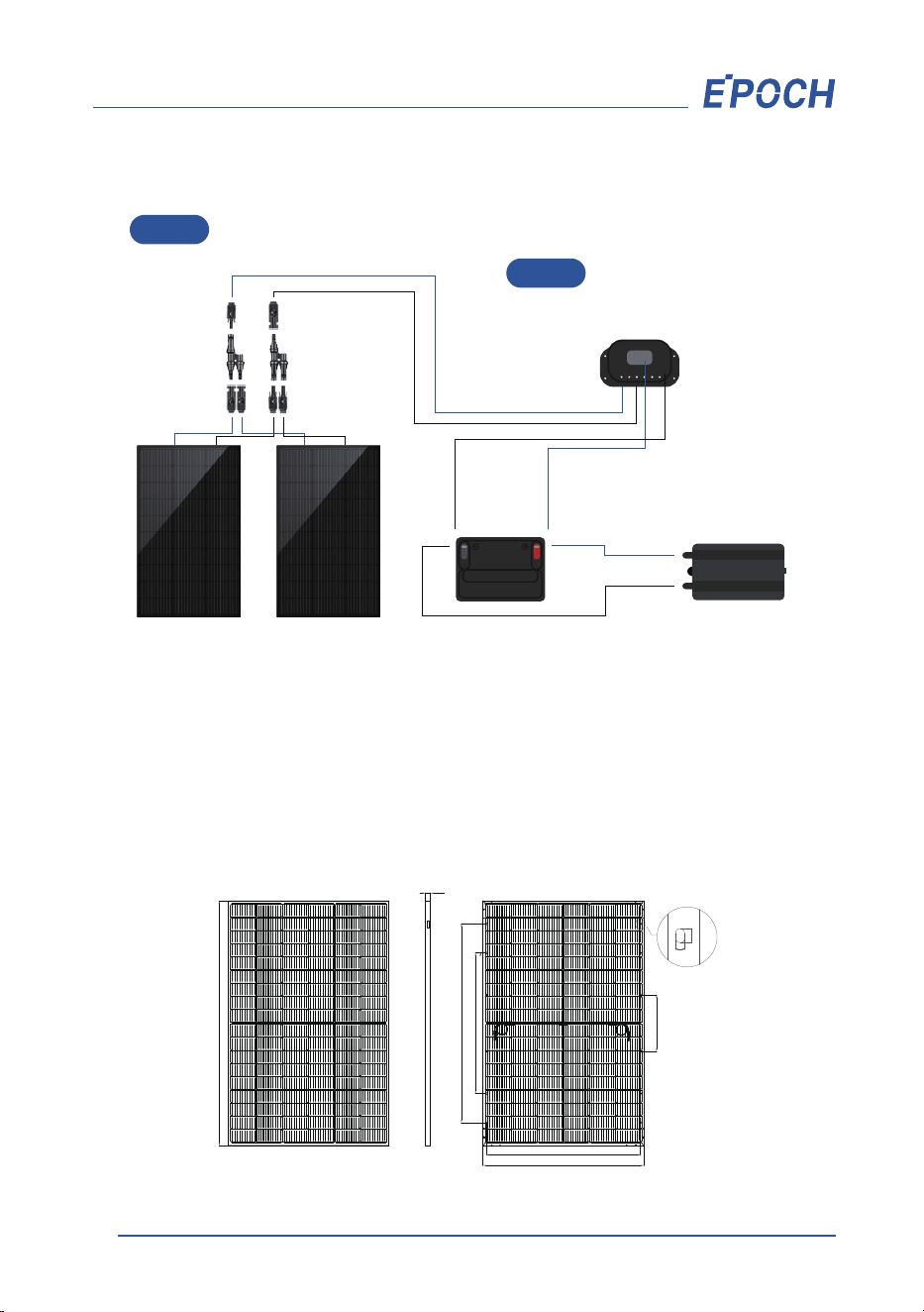
Module mounting must use the pre-drilled mounting holes in the frame. Refer to the picture for
more details.
Modules should be safely fixed to bear all expected loads, including wind and snow loads. A
minimum clearance of 0.25 in (6.5mm) or more between modules is required to allow for thermal
expansion of the frames.
02
Connect charge controller
and battery
Controller
Inverter
Battery
Connect PV module and
charge controller
Step 2
Step 1
Electrical Installation
Front Side Back
Mounting Hole
8:1
9
14
30
1400±2
990±2
1085±2
400±2
1722±2
1134±2
Unit: mm
Bolting
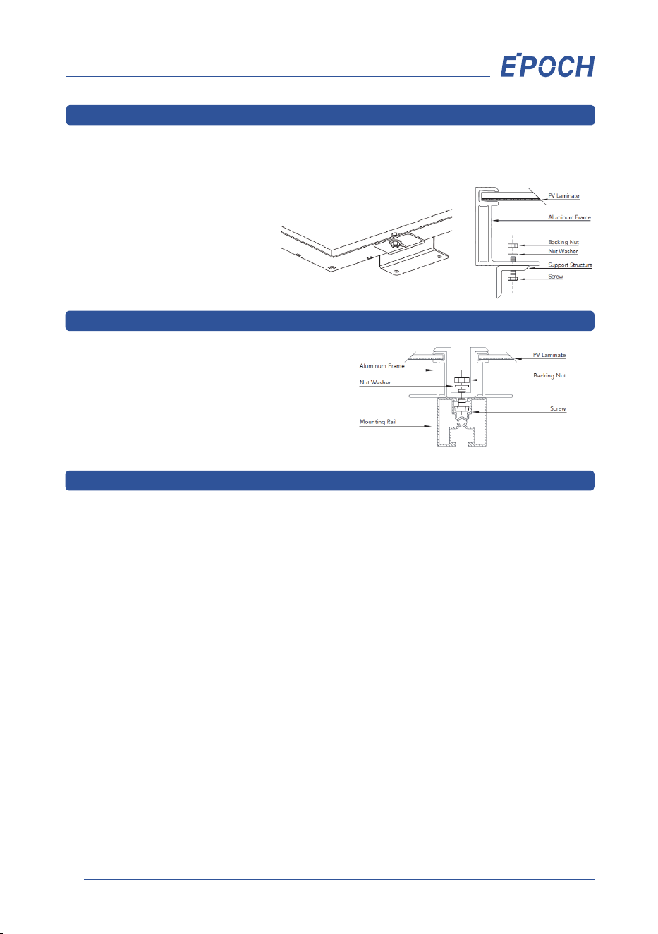
Modules must be mounted using the mounting holes located on the rear side of the long frame
parts using M6 or M8 bolt stainless steel bolts, nuts, and washers. Refer to the racking manufacturer
for specific torque requirements.
Top Down Clamps
Grounding
Clamps are an approved method of mounting
for our modules. A clamp holds two modules in
a row. The centerline of the clamps must be
in-line with the module mounting holes and
installed according to code.
The frame of the PV module, as well as any exposed non-current carrying metal parts of fixed
equipment that can be energized must be grounded to avoid electrical shock. We recommends
grounding all PV module frames to ensure the voltage between the conductive equipment and the
earth ground is zero in all circumstances.
The frame rails have pre-drilled holes marked with the grounding sign. Do not drill additional holes
into the frame rails.
◦ Clean the glass surface of the module as necessary. Always use water and a soft sponge or cloth
for cleaning. A mild, non-abrasive cleaning agent can be used to remove stubborn dirt.
◦ Check the electrical and mechanical connections every six months to verify that they are clean,
secure and undamaged.
◦ If any problem arises, have them investigated by a competent specialist. Observe the
maintenance instructions for all components used in the system, such as support frames,
charging regulators, inverters, batteries, etc.
Maintenance
03
The mounting design must be
certified by a registered professional
engineer and comply with local
code requirements from relevant
authorities.