Model
HE041
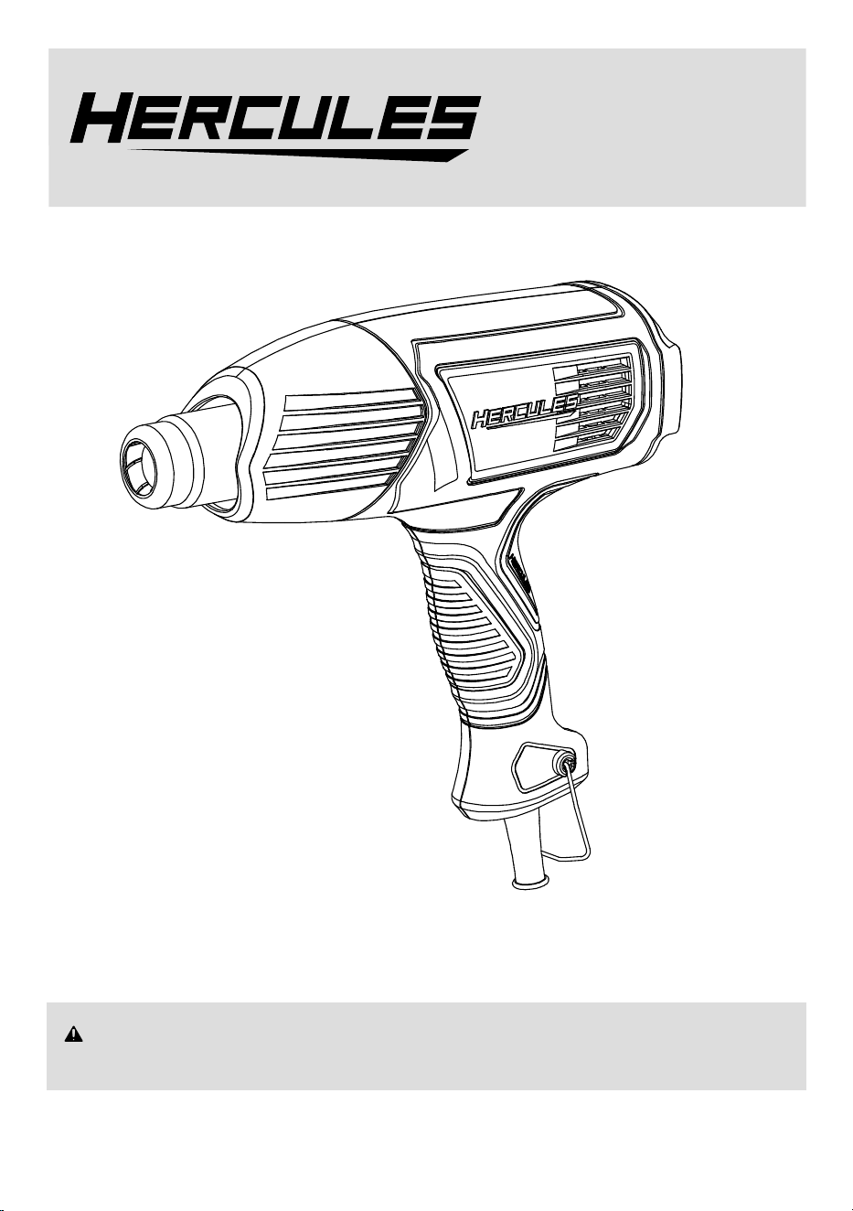
1700 Watt Heat Gun
WARNING: To prevent serious injury, User must read and understand
Owner’s Manual. SAVE THIS MANUAL.
When unpacking, make sure that the product is intact and undamaged.
If any parts are missing or broken, please visit harborfreight.com/customer-support/contact-us
as soon as possible. Reference 57988.
®
Owner’s Manual &
Safety Instructions
26j

Page 2
For product assistance, please visit harborfreight.com/customer-support/contact-us
Item 57988
IMPORTANT SAFETY INSTRUCTIONS
READ THESE INSTRUCTIONS
Heat Gun Safety Warnings
WARNING: Extreme care should be taken when
stripping paint. The peelings, residue and vapors of
paint may contain lead, which is poisonous. Any pre-
1977 paint may contain lead and paint applied to homes
prior to 1950 is likely to contain lead. Once deposited
on surfaces, hand-to-mouth contact can result in the
ingestion of lead. Exposure to even low levels of
lead can cause irreversible brain and nervous system
damage; young and unborn children are particularly
vulnerable. Before beginning any paint removal
process you should determine whether the paint you
are removing contains lead. This can be done by your
local health department or by a professional who uses
a paint analyzer to check the lead content of the paint
to be removed. LEAD-BASED PAINT SHOULD ONLY
BE REMOVED BY A PROFESSIONAL AND SHOULD
NOT BE REMOVED BY USING A HEAT GUN.
Persons removing paint should follow these guidelines:
1. Move the work piece outdoors.
If this is not possible, keep the work area well
ventilated. Open the windows and put an
exhaust fan in one of them. Be sure the fan
is moving the air from inside to outside.
2. Remove or cover any carpets, rugs, furniture,
clothing, cooking utensils and air ducts.
3. Place drop cloths in the work area to catch any
paint chips or peelings. Wear protective clothing
such as extra work shirts, overalls and hats.
4. Work in one room at a time. Furnishings should be
removed or placed in the center of the
room and covered. Work areas should
be sealed off from the rest of the dwelling
by sealed doorways with drop cloths.
5. Children, pregnant or potentially pregnant
women, and nursing mothers should not
be present in the work area until the work
is done and all clean up is complete.
6. Wear a dust respirator mask or a dual filter
(dust and fume) respirator mask which has been
approved by the Occupational Safety and Health
Administration (OSHA), the National Institute
of Safety and Health (NIOSH), or the United
States Bureau of Mines. These masks and
replaceable filters are readily available at major
hardware stores. Make sure the mask fits. Beards
and facial hair may keep masks from sealing
properly. Change filters often. DISPOSABLE
PAPER MASKS ARE NOT ADEQUATE.
7. Use caution when operating the Heat Gun.
Keep the Heat Gun moving as excessive
heat will generate fumes which can
be inhaled by the operator.
8. Keep food and drink out of the work area.
Wash hands, arms and face and
rinse mouth before eating or drinking.
Do not smoke or chew tobacco in the work area.
9. Clean up all removed paint and
dust by wet mopping the floors.
Use a wet cloth to clean all walls, sills and any
other surface where paint or dust is clinging.
DO NOT SWEEP, DRY DUST OR VACUUM.
Use a high phosphate detergent or trisodium
phosphate (TSP) to wash and mop areas.
10. At the end of each work session put the paint
chips and debris in a double plastic bag, close it
with tape or twist ties and dispose of properly.
11. Remove protective clothing and work shoes in
the work area to avoid carrying dust into the rest
of the dwelling. Wash work clothes separately.
Wipe shoes off with a wet rag that is then
washed with the work clothes. Wash hair
and body thoroughly with soap and water.
12. Hidden areas behind walls, ceilings, floors, soffit
boards, and other panels may contain flammable
materials that could be ignited by the heat gun
when working in these locations. The ignition
of these materials may not be readily apparent
and could result in property damage and injury
to persons. When working in these locations,
keep the heat gun moving in a back-and-forth
motion. Lingering or pausing in one spot could
ignite the panel or the material behind it.
13. CAUTION – To reduce the risk of
electric shock, keep extension cord
connection dry and off the ground.
14. When working with plastics, varnish, or
similar materials, gases develop that are
easily flammable and can lead to explosions.
Be prepared for flames to develop and keep
suitable fire extinguishing means at hand.
15. The Nozzle becomes very hot. Do not lay the
Heat Gun on flammable surfaces when operating
the Gun or immediately after turning the Gun off.
Always set the Heat Gun on a flat, level surface
so that the Nozzle tip is directed upwards
and away from the supporting surface.
16. Do not use the Heat Gun near flammable materials.

Page 3
For product assistance, please visit harborfreight.com/customer-support/contact-us
Item 57988
17. Do not point the Heat Gun at people or
animals. The intense heat can injure them.
18. Do not touch the tube of the heating
element or the Nozzle when they are hot.
They will be hot enough to cause burns
during use and for some time afterwards.
19. Do not use the Heat Gun on glass.
20. Do not use the Heat Gun as a hair dryer.
21. Do not heat up materials that can be
damaged by high temperatures.
Personal Safety
1. Only use safety equipment that has been approved
by an appropriate standards agency. Unapproved
safety equipment may not provide adequate
protection. Eye protection must be ANSI-approved
and breathing protection must be NIOSH-approved
for the specific hazards in the work area.
2. Avoid unintentional starting.
Prepare to begin work before turning on the tool.
3. Do not leave the tool unattended when it is plugged
into an electrical outlet. Turn off the tool, and
unplug it from its electrical outlet before leaving.
4. This product is not a toy.
Keep it out of reach of children.
5. People with pacemakers should consult their
physician(s) before use. Electromagnetic fields in
close proximity to heart pacemaker could cause
pacemaker interference or pacemaker failure.
In addition, people with pacemakers should:
• Avoid operating alone.
• Do not use with Switch locked on.
• Properly maintain and inspect to avoid
electrical shock.
• Properly ground power cord.
Ground Fault Circuit Interrupter (GFCI)
should also be implemented – it prevents
sustained electrical shock.
6. The warnings, precautions, and instructions
discussed in this instruction manual cannot
cover all possible conditions and situations
that may occur. It must be understood by the
operator that common sense and caution are
factors which cannot be built into this product,
but must be supplied by the operator.
Service
1. Have your power tool serviced by a
qualified repair person using only identical
replacement parts. This will ensure that the
safety of the power tool is maintained.
2. Maintain labels and nameplates on
the tool. These carry important safety
information. If unreadable or missing, contact
Harbor Freight Tools for a replacement.
SAVE THESE
INSTRUCTIONS.
Page 4
For product assistance, please visit harborfreight.com/customer-support/contact-us
Item 57988
GROUNDING
TO PREVENT ELECTRIC SHOCK AND
DEATH FROM INCORRECT GROUNDING
WIRE CONNECTION:
Check with a qualified electrician if you are
in doubt as to whether the outlet is properly
grounded. Do not modify the power cord plug
provided with the tool. Never remove the
grounding prong from the plug. Do not use the
tool if the power cord or plug is damaged.
If damaged, have it repaired by a service facility
before use. If the plug will not fit the outlet, have a
proper outlet installed by a qualified electrician.
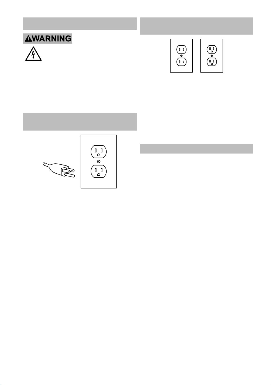
Grounded Tools: Tools with
Three Prong Plugs
3-Prong Plug and Outlet
1. Tools marked with “Grounding Required” have
a three wire cord and three prong grounding
plug. The plug must be connected to a properly
grounded outlet. If the tool should electrically
malfunction or break down, grounding provides
a low resistance path to carry electricity away
from the user, reducing the risk of electric shock.
(See 3-Prong Plug and Outlet.)
2. The grounding prong in the plug is connected
through the green wire inside the cord to the
grounding system in the tool. The green wire
in the cord must be the only wire connected to
the tool’s grounding system and must never
be attached to an electrically “live” terminal.
(See 3-Prong Plug and Outlet.)
3. The tool must be plugged into an appropriate outlet,
properly installed and grounded in accordance
with all codes and ordinances. The plug and outlet
should look like those in the preceding illustration.
(See 3-Prong Plug and Outlet.)
Double Insulated Tools: Tools
with Two Prong Plugs
Outlets for 2-Prong Plug
1. Tools marked “Double Insulated” do not
require grounding. They have a special
double insulation system which satisfies
OSHA requirements and complies with
the applicable standards of Underwriters
Laboratories, Inc., the Canadian Standard
Association, and the National Electrical Code.
2. Double insulated tools may be used in either of the
120 volt outlets shown in the preceding illustration.
(See Outlets for 2-Prong Plug.)
Extension Cords
1. Grounded tools require a three wire extension cord.
Double Insulated tools can use either
a two or three wire extension cord.
2. As the distance from the supply outlet increases,
you must use a heavier gauge extension cord.
Using extension cords with inadequately sized wire
causes a serious drop in voltage, resulting in loss of
power and possible tool damage. (See Table A.)
3. The smaller the gauge number of the wire, the
greater the capacity of the cord. For example,
a 14 gauge cord can carry a higher current
than a 16 gauge cord. (See Table A.)
4. When using more than one extension cord
to make up the total length, make sure
each cord contains at least the minimum
wire size required. (See Table A.)
5. If you are using one extension cord for more
than one tool, add the nameplate amperes
and use the sum to determine the required
minimum cord size. (See Table A.)
6. If you are using an extension cord outdoors, make
sure it is marked with the suffix “W-A” (“W” in
Canada) to indicate it is acceptable for outdoor use.
Page 5
For product assistance, please visit harborfreight.com/customer-support/contact-us
Item 57988
7. Make sure the extension cord is properly wired
and in good electrical condition. Always replace
a damaged extension cord or have it repaired
by a qualified electrician before using it.
8. Protect the extension cords from sharp objects,
excessive heat, and damp or wet areas.
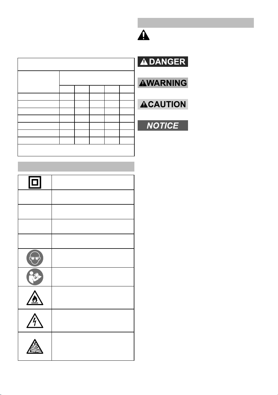
TABLE A: RECOMMENDED MINIMUM WIRE
GAUGE FOR EXTENSION CORDS* (120/240 VOLT)
NAMEPLATE
AMPERES
(at full load)
EXTENSION CORD
LENGTH
25´ 50´ 75´ 100´ 150´
0 – 2.0 18 18 18 18 16
2.1 – 3.4 18 18 18 16 14
3.5 – 5.0 18 18 16 14 12
5.1 – 7.0 18 16 14 12 12
7.1 – 12.0 18 14 12 10 -
12.1 – 16.0 14 12 10 - -
16.1 – 20.0 12 10 - - -
* Based on limiting the line voltage drop to five volts at
150% of the rated amperes.
Symbology
Double Insulated
V
Volts
~
Alternating Current
A
Amperes
n
0
xxxx/min.
No Load Revolutions
per Minute (RPM)
WARNING marking concerning Risk
of Eye Injury. Wear ANSI-approved
safety goggles with side shields.
Read the manual before
set-up and/or use.
WARNING marking
concerning Risk of Fire.
Do not cover ventilation ducts.
Keep flammable objects away.
WARNING marking concerning
Risk of Electric Shock.
Properly connect power cord
to appropriate outlet.
WARNING marking concerning
Risk of Explosion.
Do not puncture, short, or open
battery packs and do not charge
damaged battery packs.
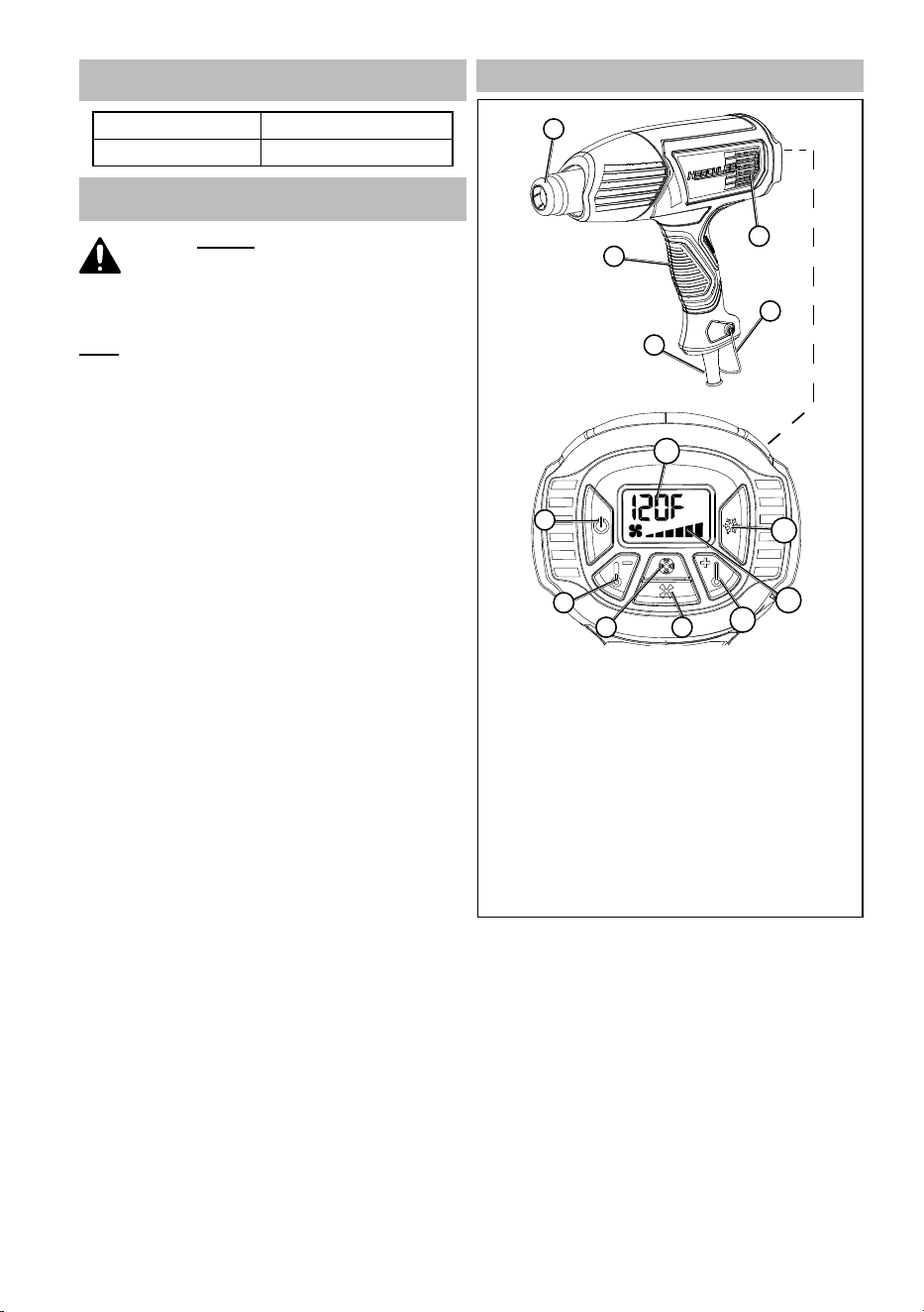
Warning Symbols and Definitions
This is the safety alert symbol. It is used to
alert you to potential personal injury hazards.
Obey all safety messages that follow this symbol to
avoid possible injury or death.
Indicates a hazardous
situation which, if not
avoided, will result in death or serious injury.
Indicates a hazardous
situation which, if not
avoided, could result in death or serious injury.
Indicates a hazardous
situation which, if not
avoided, could result in minor or moderate injury.
Addresses practices not
related to personal injury.
Page 6
For product assistance, please visit harborfreight.com/customer-support/contact-us
Item 57988
SPECIFICATIONS
Electrical Rating 120VAC / 60Hz / 1700W
Temperature Range 120°F - 1200°F
SETUP - BEFORE USE:
Read the ENTIRE IMPORTANT
SAFETY INFORMATION section at the
beginning of this manual including
all text under subheadings therein
before set up or use of this product.
Note: For additional information regarding the parts
listed in the following pages, refer to Component
List and Assembly Diagram on page 11.
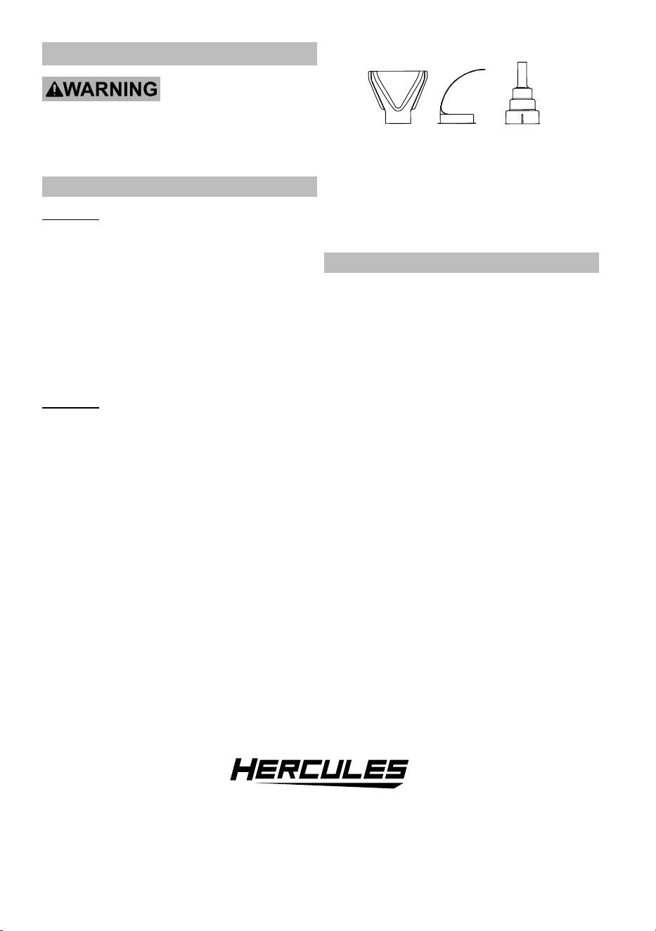
Functions
1. Nozzle
2. Air Intake
3. Hook
4. Handle
5. Power Cord
1
2
3
4
5
Rear Panel Buttons
6. Power ON/OFF.
7. Decrease temperature.
8. Increase fan speed.
9. Decrease fan speed.
10. Increase temperature.
11. Fan air flow Indicator, graph
expands as speed increases.
12. Cool Down.
13. Temperature Display.
6
8
7
9
10
12
11
13
Page 7
For product assistance, please visit harborfreight.com/customer-support/contact-us
Item 57988
Tool Changing
TO PREVENT SERIOUS INJURY FROM
ACCIDENTAL OPERATION:
Make sure that the Switch is in the off-position
and unplug the tool from its electrical outlet
before performing any procedure in this section.
Accessory Nozzles
WARNING! Only use the accessories included with
the Heat Gun. Other accessories may damage the
tool, become stuck, or not be secured properly.
1. The Heat Gun can be used alone or
with an accessory nozzle attached.
a. To attach an accessory nozzle, push
it into the Heat Gun nozzle.
b. To remove the accessory nozzle, turn off
Heat Gun and allow it to cool. Grasp the
Nozzle Cover and turn it counter clockwise
to eject the accessory nozzle onto a non-
flammable surface, away from people.
WARNING! Risk of burns! The Accessory Nozzle
becomes very hot when the Heat Gun is in use
and remains hot for a while after use. Allow it
to cool out of reach of people and animals.
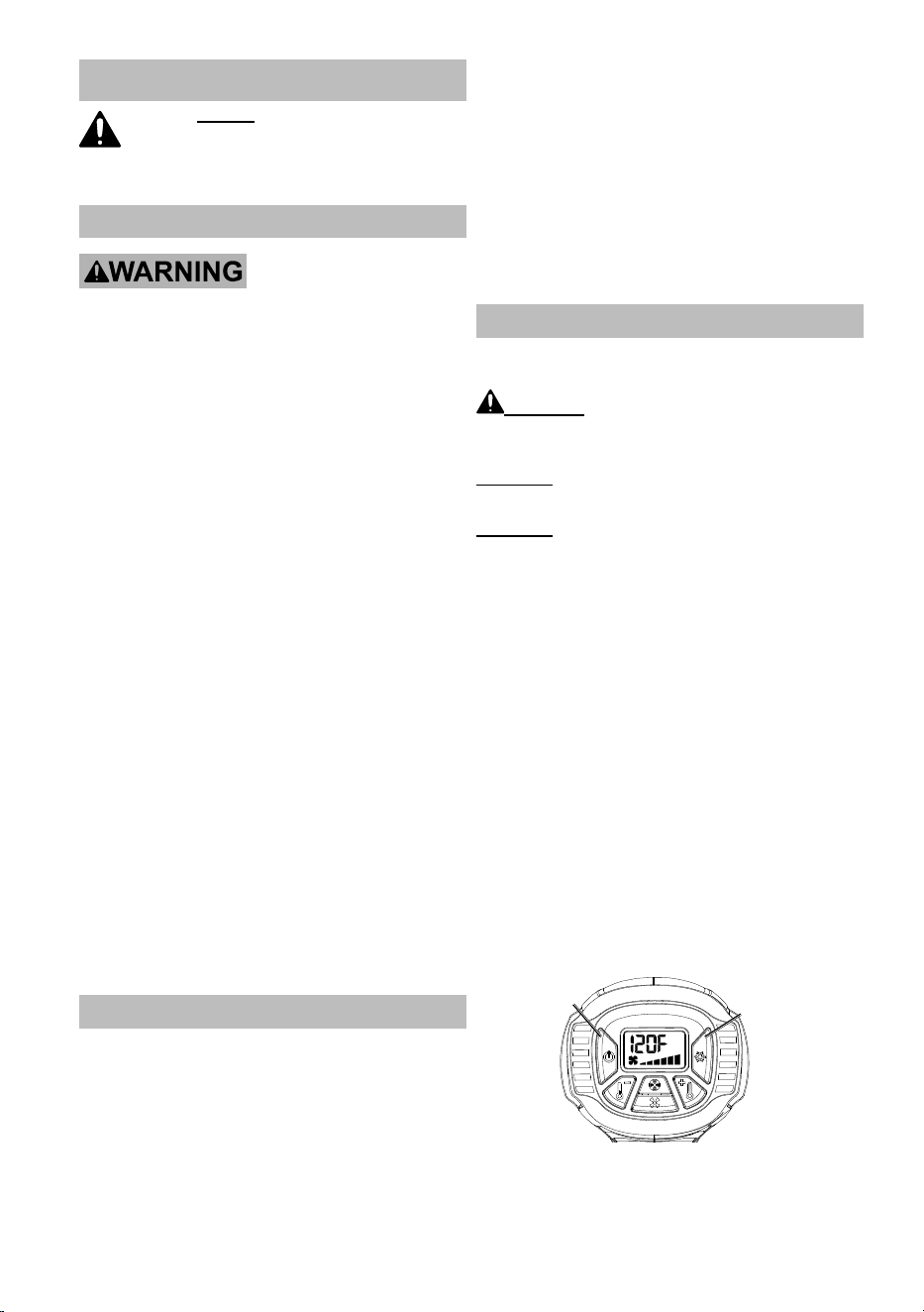
2. Three accessory nozzles are provided:
Flat Nozzle
Reflector
Nozzle
Concentration
Nozzle
a. Use the Flat Nozzle to dry paint or to
peel off self-adhesive tapes/stickers.
b. Use the Reflector Nozzle for shrinking heat-
shrink tubing or bending PVC pipe.
c. Use the Concentration Nozzle for soldering/
de-soldering electronic components.
Hook
1. Hook may be used to hang heat gun or to
provide stability during stationary use.
2. Return hook leg under handle when not in use.
®
Page 8
For product assistance, please visit harborfreight.com/customer-support/contact-us
Item 57988
OPERATING INSTRUCTIONS
Read the ENTIRE IMPORTANT
SAFETY INFORMATION section at the
beginning of this manual including
all text under subheadings therein
before set up or use of this product.
Uses
TO PREVENT SERIOUS INJURY FROM
ACCIDENTAL OPERATION:
Make sure that Power Switch is in the off-position
and unplug the tool from its electrical outlet before
adjusting tool or installing accessories.
The low 120°F setting of the Heat
Gun can be used for cooling.
The high heat settings of Heat Gun can be used for:
• Shrinking of shrink tubing, packaging
and electrical components.
• Deforming of articles made from acrylic, PVC,
and polystyrene tubing, plates, and profiles.
• Welding of thermoplastic polymer, flooring
materials of PVC and linoleum, PVC-coated
fabric, wallpaper, tarpaulins and foils.
• Soldering of tin, special silver solder, SMD elements,
cable lugs, and for loosening soldered connections.
• Paint removal. Removal of old coatings of
oil paint, varnish, and synthetic plaster.
• Drying of color shade samples, filter, adhesives,
construction joints and stucco forms.
• Joining adhesives. Large surface gluing with
contact adhesives, activation of pressure, or heat
sensitive adhesives, acceleration of bonding
processes, releasing of bonding points as well
as releasing or bonding of edge bond or veneer.
• Defrosting of icy stairs and steps, door locks,
trunk lids, car doors or metal water pipes.
• Disinfection. With the tool set at the
highest setting, animal sites/stables may
be disinfected. Wood worm infestation
may be controlled. Do not heat up the
wood surface too much or it can burn.
Workpiece and Work Area Set Up
1. Designate a work area that is clean and well lit.
The work area must not allow access by children
or pets to prevent distraction and injury.
2. Route the power cord along a safe route to reach
the work area without creating a tripping hazard or
exposing the power cord to possible damage. The
power cord must reach the work area with enough
extra length to allow free movement while working.
3. Secure loose workpieces using a vise or clamps
(not included) to prevent movement while working.
4. There must not be objects, such as utility lines,
nearby that will present a hazard while working.
5. Remove all flammable and heat sensitive
materials from the work area.
6. Plan an insulated, non-flammable surface
for the gun to cool down on after use.
7. Keep multiple class ABC fire extinguishers readily
accessible while working and while workpiece cools.
General Operating Instructions
1. Plug the Power Cord of the tool into a
120 volt, grounded, electrical outlet.
WARNING! To prevent personal serious injury
or property damage, do not leave the Heat Gun
unattended while pointed at surfaces or objects.
CAUTION! Do not touch work area with
the Heat Gun; it could scorch or ignite.
CAUTION! Do not block Air Vents when Heat Gun
is in use, it could cause the tool to over-heat.
2. Press the Power Switch on the rear
panel of the unit. Press once to power
ON and again to power OFF.
3. The Heat Gun will start at the lowest
temperature of 120°F. A little smoke may
emit from the unit for a short time. This is
normal and does not indicate a problem.
4. Press the Temperature buttons to adjust
temperature. A short press will adjust
in ten-degree increments. A long press
will increase temperature quickly.
5. Allow the Heat Gun one minute to build
up to the desired heat level.
6. The Temperature Display will change as the
temperature resets and will stabilize when
the unit reaches the setting temperature.
7. To change from Celsius to Fahrenheit,
press and hold the Cool Down button then
press and release the Power button.
Power
Button
Cool Down
Button
8. Choose the appropriate heat level and
fan output for the job. Press the Fan
Speed buttons to adjust speed.
Page 9
For product assistance, please visit harborfreight.com/customer-support/contact-us
Item 57988
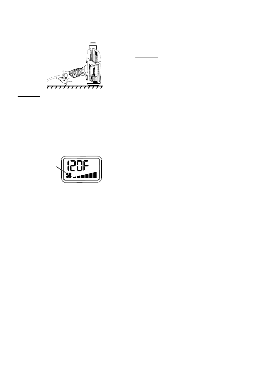
9. The Heat Gun can be used in stationary mode
by placing it on a stable flat surface. Use the
Hook to provide stability. Secure the power
cable to prevent the tool from falling.
Hook
CAUTION! Do not drop anything into the Nozzle.
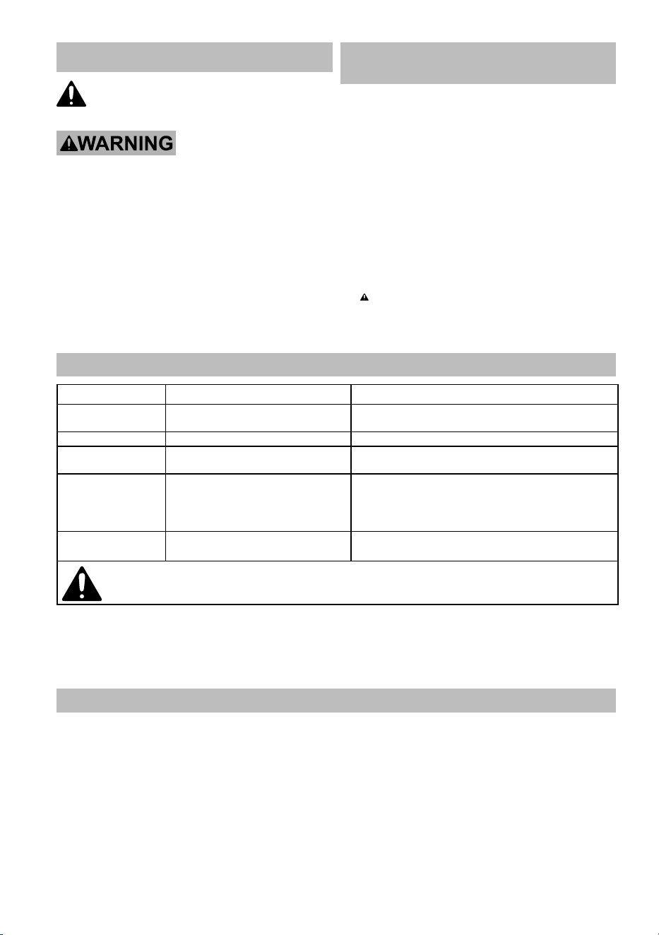
10. Before moving or storing the Heat Gun,
power OFF the tool. After pressing the Power
button to turn the Heat Gun OFF, the tool will
automatically go into Cool Down Mode:
a. The unit will stop heating
b. The fan icon will flash, and
c. The fan will continue to run for about
10 seconds cooling the tool.
Fan
Icon
Temperature Display
11. To prevent accidents, turn off the Heat Gun and
unplug it after use. Allow the Heat Gun to cool
down on an insulated, non-flammable surface.
CAUTION! After use, do not touch
Nozzle until it has had time to cool.
CAUTION! Do not leave work area
until Heat Gun has cooled. Be alert
for indications of concealed fire.
12. Allow time for the Heat Gun to cool then disconnect
its Power Cord after use. Clean, then store the
Heat Gun indoors out of children’s reach.
Page 10
For product assistance, please visit harborfreight.com/customer-support/contact-us
Item 57988
MAINTENANCE AND SERVICING
Procedures not specifically explained
in this manual must be performed
only by a qualified technician.
TO PREVENT SERIOUS INJURY
FROM ACCIDENTAL OPERATION:
Make sure that the Power Switch is in the
off-position and unplug the tool from its electrical
outlet before performing any inspection,
maintenance, or cleaning procedures.
TO PREVENT SERIOUS INJURY FROM TOOL
FAILURE:
Do not use damaged equipment.
If abnormal noise or vibration occurs, have
the problem corrected before further use.
Cleaning, Maintenance,
and Lubrication
1. BEFORE EACH USE, inspect the general
condition of the tool. Check for:
• loose hardware,
• misalignment or binding of moving parts,
• cracked or broken parts,
• blocked Air Vents,
• damaged electrical wiring, and
• any other condition that may
affect its safe operation.
2. AFTER USE, wipe external surfaces
of the tool with clean cloth.
3. WARNING! TO PREVENT SERIOUS
INJURY: If the supply cord of this power
tool is damaged, it must be replaced only
by a qualified service technician.
Troubleshooting
Problem Possible Causes Likely Solutions
Tool will not start. Internal damage or wear. (Carbon
brushes or Switch, for example.)
Have technician service tool.
Tool operates slowly. Forcing tool to work too fast. Allow tool to work at its own rate.
Excessive noise
or rattling.
Internal damage or wear. (Carbon
brushes or bearings, for example.)
Have technician service tool.
Overheating. 1. Forcing tool to work too fast.
2. Blocked motor housing vents.
1. Allow tool to work at its own rate.
2. Wear ANSI-approved safety goggles and
NIOSH-approved dust mask/respirator while
blowing dust out of motor using compressed air.
Unsatisfactory
results.
Inappropriate heat for task. Adjust heat setting or distance to
workpiece to compensate.
Follow all safety precautions whenever diagnosing or servicing the tool.
Disconnect power supply before service.
PLEASE READ THE FOLLOWING CAREFULLY
THE MANUFACTURER AND/OR DISTRIBUTOR HAS PROVIDED THE COMPONENT LIST AND ASSEMBLY
DIAGRAM IN THIS MANUAL AS A REFERENCE TOOL ONLY. NEITHER THE MANUFACTURER OR
DISTRIBUTOR MAKES ANY REPRESENTATION OR WARRANTY OF ANY KIND TO THE BUYER THAT HE
OR SHE IS QUALIFIED TO MAKE ANY REPAIRS TO THE PRODUCT, OR THAT HE OR SHE IS QUALIFIED
TO REPLACE ANY PARTS OF THE PRODUCT. IN FACT, THE MANUFACTURER AND/OR DISTRIBUTOR
EXPRESSLY STATES THAT ALL REPAIRS AND PARTS REPLACEMENTS SHOULD BE UNDERTAKEN BY
CERTIFIED AND LICENSED TECHNICIANS, AND NOT BY THE BUYER. THE BUYER ASSUMES ALL RISK
AND LIABILITY ARISING OUT OF HIS OR HER REPAIRS TO THE ORIGINAL PRODUCT OR REPLACEMENT
PARTS THERETO, OR ARISING OUT OF HIS OR HER INSTALLATION OF REPLACEMENT PARTS THERETO.
Page 11
For product assistance, please visit harborfreight.com/customer-support/contact-us
Item 57988
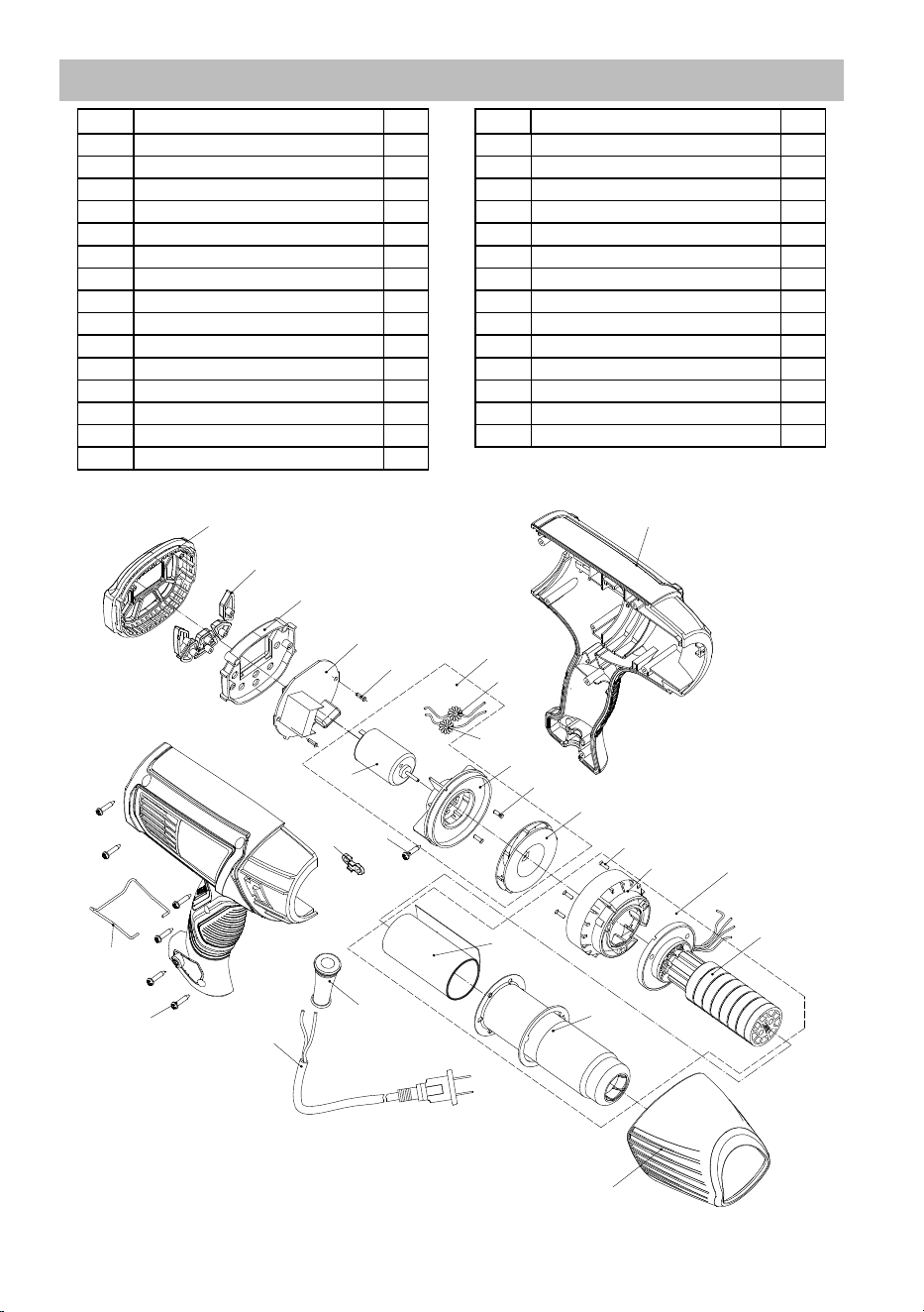
COMPONENT LIST AND ASSEMBLY DIAGRAM
Part Description Qty
1 Left & Right Housing Assembly 1
2 Back Cover 1
3 Control Buttons 1
4 Back Inner Cover 1
5 PCB Assembly 1
6 Screw 2
7 Motor-Fan Assembly 1
7.1 Magnetic Ring 1
7.2 Magnetic Ring 1
7.3 Motor 1
7.4 Motor Support 1
7.5 Screw 2
7.6 Fan Assembly 1
8 Heating Element Assembly 1
8.1 Screw 3
Part Description Qty
8.2 Fan Cover 1
8.3 Heating Element 1
8.4 Mica Paper 2
8.5 Steel Can 1
9 Front Cover 1
10 Screw 3
11 Cord Clamp 1
12 Cord Sleeve 1
13 Power Cord 1
14 Screw 6
15 Hook 1
17 Flat Nozzle (not shown) 1
18 Reflector Nozzle (not shown) 1
19 Concentration Nozzle (not shown) 1
7.1
7.2
7 .3
7 .4
7.5
7.6
8.1
8.2
8 .3
8.4
8.5
1
6
3
2
5
4
7
8
9
10
1 1
12
13
14
15

3-YEAR LIMITED WARRANTY
This HERCULES tool is warranted to the original purchaser to be free from defects in materials and
workmanship for a period of three (3) years beginning on the date of purchase. To obtain warranty
service, visit your local Harbor Freight retail store. Warranty registration is not required. The product
or part must be returned to us with proof of purchase (e.g. in-store receipt or packing slip/invoice)
and may require shipment by purchaser to a service center at purchaser’s expense. If our inspection
verifies a covered defect in materials or workmanship during the warranty period, we will, at our option,
repair or replace the defective product. We will return repaired products within a reasonable time at our
expense, but if we determine that there is no defect, or that the defect resulted from causes not within
the scope of our warranty, then we will return the product to you if you pay return shipping costs.
This warranty does not cover any failure or damage that we determine is due directly or indirectly
to normal wear and tear, misuse, use not for the intended purpose or not in accordance with the
product manual, abuse, accident, rental, modification or alteration, unauthorized repair, improper
installation, neglect, lack of maintenance, or any other failure not arising from defective materials or
workmanship. Fraudulent returns or claims will be denied. The repair or replacement described in this
warranty shall be your sole and exclusive remedy. THIS WARRANTY IS EXCLUSIVE AND IN LIEU
OF ALL OTHER EXPRESS WARRANTIES, WRITTEN OR ORAL, AND ANY IMPLIED WARRANTIES
ARE DISCLAIMED TO THE EXTENT PERMITTED BY LAW AND OTHERWISE LIMITED TO THE
DURATION OF THE EXPRESS WARRANTY HEREIN. HARBOR FREIGHT SHALL NOT BE LIABLE
UNDER ANY CIRCUMSTANCES FOR ANY INCIDENTAL, INDIRECT, SPECIAL, CONSEQUENTIAL,
OR PUNITIVE DAMAGES OR COSTS ARISING FROM THIS WARRANTY OR THE USE OF THIS
PRODUCT. SOME STATES DO NOT ALLOW LIMITATIONS ON HOW LONG AN IMPLIED WARRANTY
LASTS OR THE EXCLUSION OR LIMITATION OF INCIDENTAL OR CONSEQUENTIAL DAMAGES, SO
THESE LIMITATIONS MAY NOT APPLY TO YOU. THIS WARRANTY GIVES YOU SPECIFIC LEGAL
RIGHTS, AND YOU MAY ALSO HAVE OTHER RIGHTS WHICH VARY FROM STATE TO STATE.
Copyright
©
2026 by Harbor Freight Tools
®
. All rights reserved. No portion of this manual or any artwork contained herein
may be reproduced in any shape or form without the express written consent of Harbor Freight Tools. Diagrams within
this manual may not be drawn proportionally. Due to continuing improvements, actual product may differ slightly
from the product described herein. Tools required for assembly and service may not be included.
®
For product assistance, visit harborfreight.com/customer-support/contact-us
Record Product’s Date Code Here:
Note: If product has no Date Code, record month and year of purchase instead.
Note: The component list and assembly diagram are shown for reference only.
To view all currently available replacement parts, please visit harborfreight.com/parts
Specify UPC 193175429704 when ordering parts.
Visit our website at: https://www.harborfreight.com
For product assistance, visit harborfreight.com/customer-support/contact-us