� us
TRENEDER
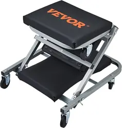
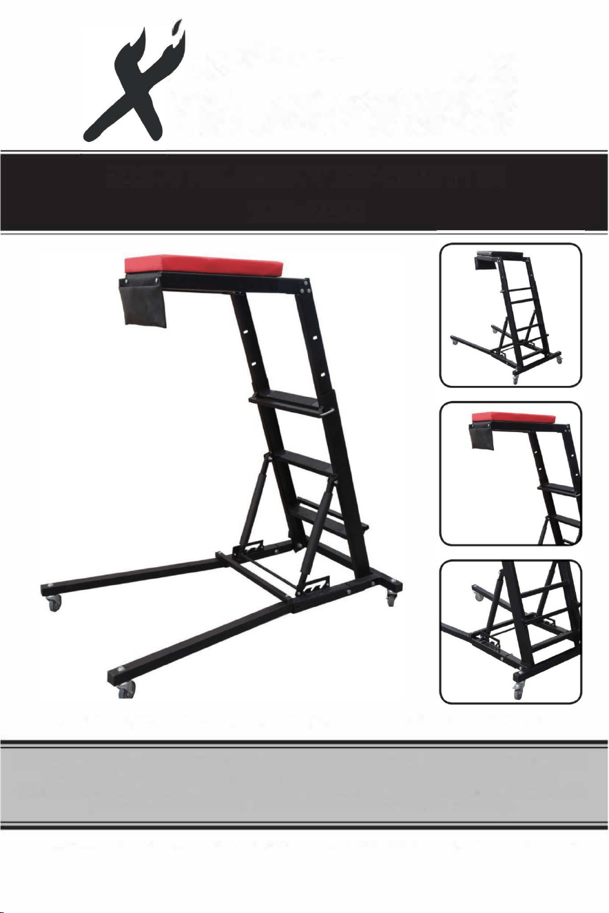
400LB FOLDABLE TOP CREEPER
ITEM: 26508
OWNER'S MANUAL AND SAFETY INSTRUCTIONS
SAVE THIS MANUAL: KEEP THIS MANUAL FOR SAFETY WARNINGS, PRECAUTIONS, ASSEMBLY,
OPERATING, INSPECTION, MAINTENANCE AND CL EANING PROCEDURES. WRITE THE
PRODUCT'S SERIAL NUMBER ON THE BACK OF THE MANUAL NEAR THE ASSEMBLY DIAGRAM
(OR MONTH AND YEAR OF PURCHASE IF PRODUCT HAS NO NUMBER).
FOR QUESTIONS PLEASE CALL OUR CUSTOMER SUPPORT: (909) 628 0880 MON-FRI 9AM TO 3PM PST

IMPORTANT SAFETY INFORMATION
GENERAL SAFETY WARNINGS
The warnings, precautions, and instructions discussed in this instruction manual cannot cover all possible
conditions and situations that may occur. It must be understood by the operator that common sense and
caution are factors which cannot be built into this product, but must be supplied by the operator. Read
carefully and understand all ASSEMBLY AND OPERATION INSTRUCTIONS before operating. Failure to
follow the safety rules and other basic safety precautions may result in serious personal injury.
• This product is a tool to reach what are normally hard to reach places, such as the topside of an engine
compartment for mechanics.
• ALWAYS inspect the product for damage before each use. Do not use if damage is detected. Make sure
all nuts and bolts are secure before each use.
• ALWAYS make sure the angle adjustment bar is secure in one of the three position slots before using.
• ALWAYS face the Topside Creeper when climbing up or down. Use both hands and keep your body
centered between the rails.
• DO NOT USE THE PRODUCT if you tire easily or are subject to fainting spells or disorientation.
• DO NOT USE THE PRODUCT if you are taking medication that could impair judgement or are under the
influence of drugs or alcohol.
• DO NOT overload the product. The maximum capacity is 400 lbs (180 kg) which includes body weight,
tools and torque applied to tools.
• DO NOT use the Topside Creeper over a running engine.
• ALWAYS wear safety goggles that provide front and side protection for the eyes.
• ALWAYS wear gloves that provide protection based in the work materials or to reduce the effects of tool
vibration.
• Store tools properly in a safe and dry location. Keep tools out of reach of children or those with diminished
capacity.
• ALWAYS ensure the height adjustment bar is securely fixed in one of the three position slots prior to
using.
• The maximum capacity listed includes the user, tools, equipment and personal items. DO NOT exceed
the maximum capacity.
• Lean your chest onto the chest pad deck gently. Avoid causing a shock load by jumping or falling onto
the chest pad deck.
• DO NOT stand or sit on the chest pad deck.
• DO NOT get the Topside Creeper wet or use in damp locations or where there is condensation.
• ONLY use the creeper on flat, level surfaces that can withstand the weight of total load.
• ALWAYS lock the casters before using the foldable topside creeper.
PARTS AND ASSEMBLY
SPECIFICATIONS
CONSTRUCTION
Powder Coated Steel
CASTERS 3 in. Swivel Casters, 3in. Locking Swivel Casters
DIMENSIONS 30.5" X 54" X 66"
ADJUSTABLE HEIGHT
can adjust between 48'' and " in height
WEIGHT CAPACITY 4LBS
PADDED DECK 18" X 12"
The foldable Topside Creeper can adjust between 48 and 64 inches in height. The heavy duty steel
construction that is powder coated for protection. A padded, high-density foam deck provides additional
comfort. This unit also folds to save space.
UNPACKING
WARNING: DO NOT operate the tool if any part is missing. Replace the missing part before operating.
Failure to do so can result in a malfunction and personal injury.
Remove the parts and accessories from the packaging and inspect for damage. Make sure all items in the
contents are included.
A
BASE FRAME
I
POUCH BRACKET
Q
HEIGHT ADJUSTMENT PLATE X2
B
LADDER ASSEMBLY
J
FRONT CASTER WITH NUT X2
R
HEIGHT ADJUSTMENT PLATE BOLT X4
C
CHEST DECK FRAME
K
REAR CASTER WITH NUT X2
s
HEIGHT ADJ UST SUPPORT BOLT X2
D
CHEST DECK PAD
L
BUMPER PADS X3
T
WASHERX2
E
RIGHT LEG
M
LEG LOCK PIN X2
u
CHEST DECK PAD BOLT X2
F
LEFT LEG
N
FRAME BOLT X4
V
LOCK NUT1 X4
G
LEG CROSS SUPPORT
0
CROSS SUPPORT BOLT X2
w
LOCK NUT2 X12
H
POUCH
p
CHEST FRAME & BRACKET BOLT XS
X
LOCK NUT3X4
ASSEMBLY
Letter references in parenthesis (A) refer to the contents above.
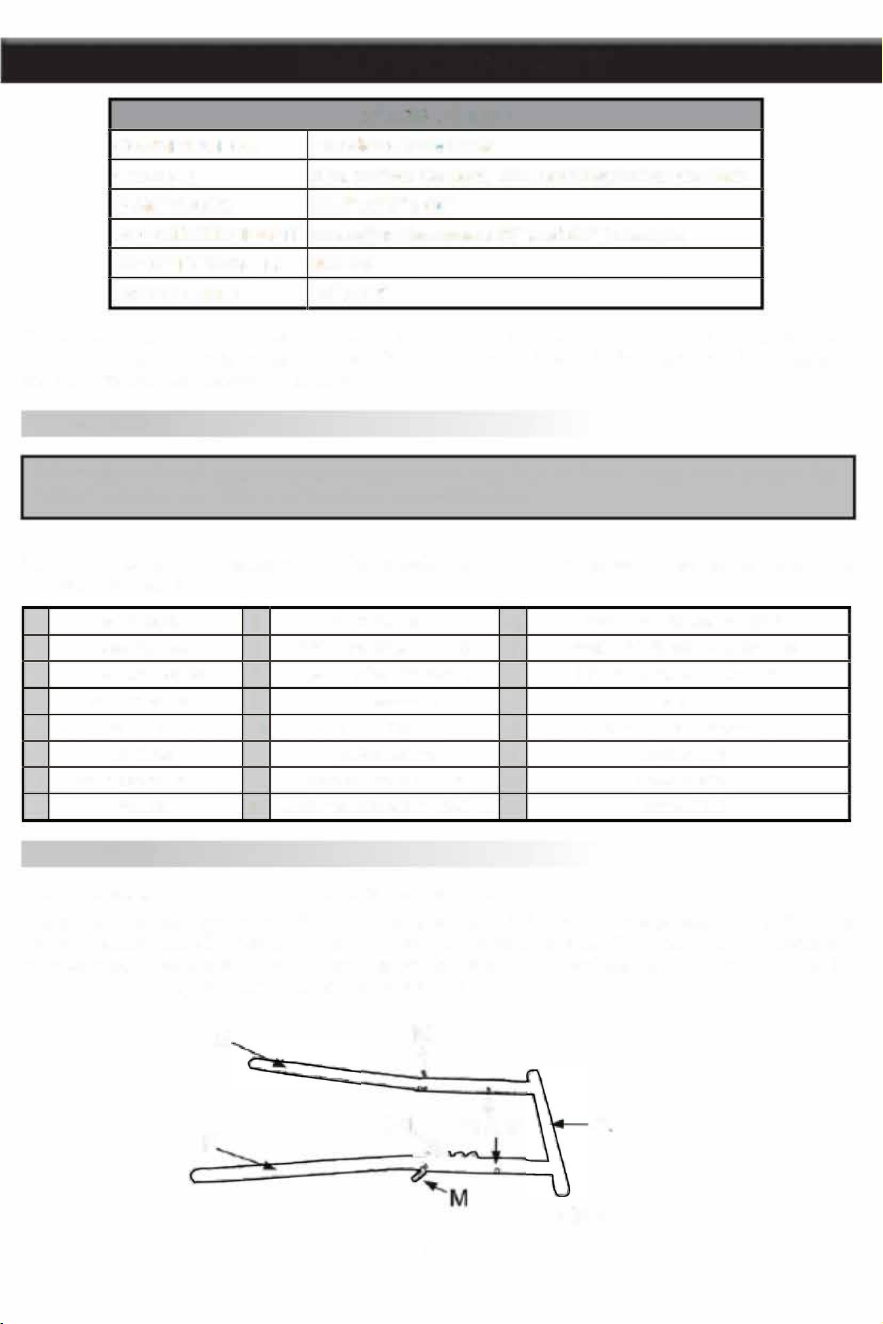
1. Assemble the right and le legs (E & F) to the base frame (A). Insert the end of each leg into the base
frame's openings and align the bolt holes. The height adjustment notches (Fig. 1) will be on the inside and
the legs must angle outwards. Secure each leg with a frame bolt (N) and lock nit 1 (V). Insert the two leg
lock pins (M) and push the ends down to secure the legs.
E
F
M
♦
♦
1-1
N & V
"
2
A
Fig. 1
ASSEMBLY
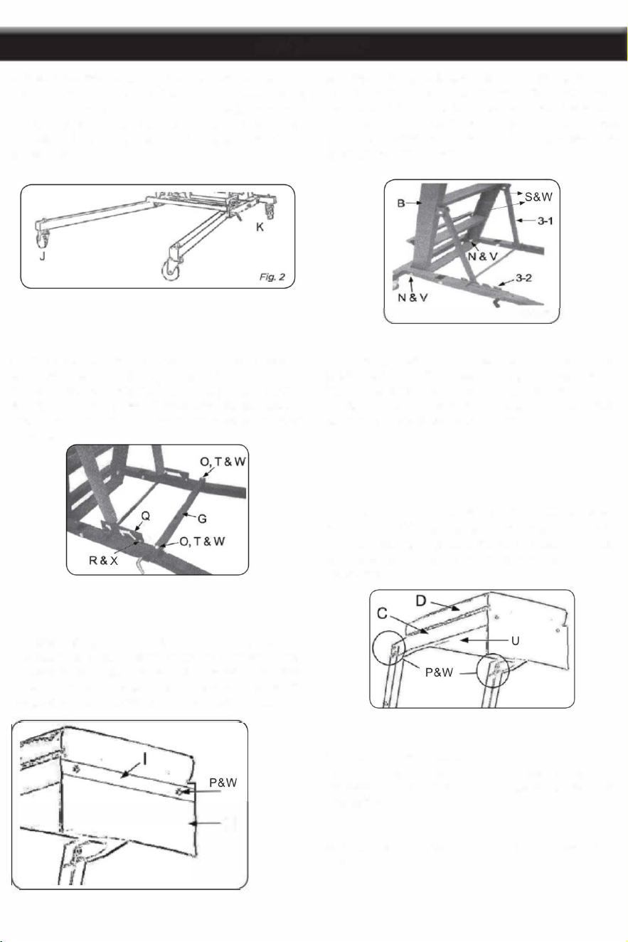
2. Attach the front casters (J) by inserting the stem of
each caster through the end of each leg and securing
it with a flange nut (U). Install the rear locking casters
(K) to the base frame in the same manner. Lock
the rear wheels in place for the remainder of the
installation.
4. Place the leg cross support (G) on both legs (E
& F), aligning the bolt holes. Insert a cross support
bolt (0) through each end of the leg cross support
and leg. Slide a washer (T) over one bolt and secure
with a lock nut 2 (W). Repeat with the other crossbar
suppo.
7. Place the pouch bracket (I) over the pouch (H)
and align the screw holes. Insert Pouch bracket bolt
(P) through the screw holes. Line up the protruding
screws with the holes in the deck frame's front.
Secure the pouch to the deck frame with screws.
H
3
3. Install the ladder assembly (B) by inserting a
frame bolt (N) through each side of the base frame
and lower ladder assembly. Secure each bolt with a
lock nut 1 (V). Swing the ladder's angle support into
the height adjustment notches (3-2). Make sure the
crossbar is firmly in place.
Fig. 3
5. Attach the height adjustment plate (Q). Match the
angled opening with the adjustment notches. Insert a
height adjustment plate bolt (R) through the bolt hole
at each end of the plate. Secure each bolt with a lock
nut 3 ( X). Repeat on the other side.
6. Attach the chest deck frame (C) to the top of the
ladder assembly (B) using three chest frame bolts
(P) and lock nut 2 ( on each side. Attach the chest
pad deck pad (D) using
chest deck pad bolt(U) from
underneath.
8. Place the foam bumper pads (L) over each of
the angle support arms and the ladder assembly's
crosspiece. This will prevent the ladder from scuffing
the vehicle.
9. Recheck and tighten all bolts and screws as
necessary.
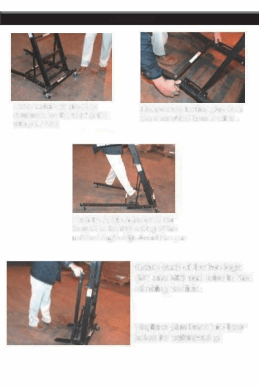
L Casters by pressi
downward on the lki tab
with yr fl
ASSEMBLY
Reve two ling pins om
the assembled se stion.
Push the Angle Adjustment Bar
fward to the first setting of the
notch Angle Adjustment Keer.
4
Grasp each of e two legs
(M1 and M2) a raise to the
climbing stion.
Replace pins back into eir
es for safekpi.

CARE AND MAINTENANCE
1. Maintain the tool with care. A tool in good condition is more efficient, easier to control and will have fewer
problems.
2. Inspect the tool components periodically. Repair or replace damaged or worn components. Only use
identical replacement parts when servicing.
3. Maintain the tool's labels and name plates. These carry important information. If unreadable or missing,
contact customer service for replacement.
WARNING: ONLY qualified service personnel should repair the tool. An improperly repaired the tool.
An improperly repaired tool may present a hazard to the user and/or others.
CLEANING
Wipe clean as needed. Use mild upholstery cleaner (not caustic) to clean the chest deck pad as needed.
LUBRICATION
DO NOT lubricate the casters. This can damage the mechanism.
STORAGE
1. Remove the leg lock pins from each leg. Hold the ladder when removing the second pin as the base frame
will fall to the floor. Store the pins in the creeper's pouch.
2. Push the ladder's angle support arms back towards the ladder.
3. Lift each leg up until it rests next to the ladder assembly.
4. Store the creeper vertically. Make sure the rear casters are locked once in place.
REMOVAL FROM STORAGE
1. Lower each leg.
2. Pull the ladder's angle support arms forward to settle in a height adjustment notch.
3. Remove the leg lock pins from the pouch.
4. Lift the base frame and push the leg down until the bolt holes align. Push the leg lock pin through and turn
the end down. Repeat with the other leg.
5. Unlock the rear casters and it is ready for use.
5

OF NOTE
PLEASE READ THE FOLLOWING CAREFULLY
THE MANUFACTURER AND/OR DISTRIBUTOR HAS PROVIDED THE PARTS LIST AND ASSEMBLY
DIAGRAM IN THIS MANUAL AS A REFERENCE TOOL ONLY. NEITHER THE MANUFACTURER OR
DISTRIBUTOR MAKES ANY REPRESENTATION OR WARRANTY OF ANY KIND TO THE BUYER THAT
HE OR SHE IS QUALIFIED TO MAKE ANY REPAIRS TO THE PRODUCT, OR THAT HE OR SHE IS
QUALIFIED TO REPLACE ANY PARTS OF THE PRODUCT. IN FACT, THE MANUFACTURER AND/OR
DISTRIBUTOR EXPRESSLY STATES THAT ALL REPAIRS AND PARTS REPLACEMENTS SHOULD BE
UNDERTAKEN BYCERTIFIEDAND LICENSED TECHNICIANS,AND NOT BY THE BUYER. THE BUYER
ASSUMES ALL RISK AND LIABILITY ARISING OUT OF HIS OR HER REPAIRS TO THE ORIGINAL
PRODUCT OR REPLACEMENT PARTS THERETO, OR ARISING OUT OF HIS OR HER INSTALLION
OF REPLACEMENT PARTS THERETO.
Record Product's Serial Number Here: _________________ _
Note: If product has no serial number, record month and year of purchase instead.
Note: Some parts are listed and shown for illustration purposes only and are not available
individually as replacement parts.
PRODUCT MADE IN CHINA
6