Operang Instrucons for the
HT/MKII
S ub-Ba ss
System
2
2
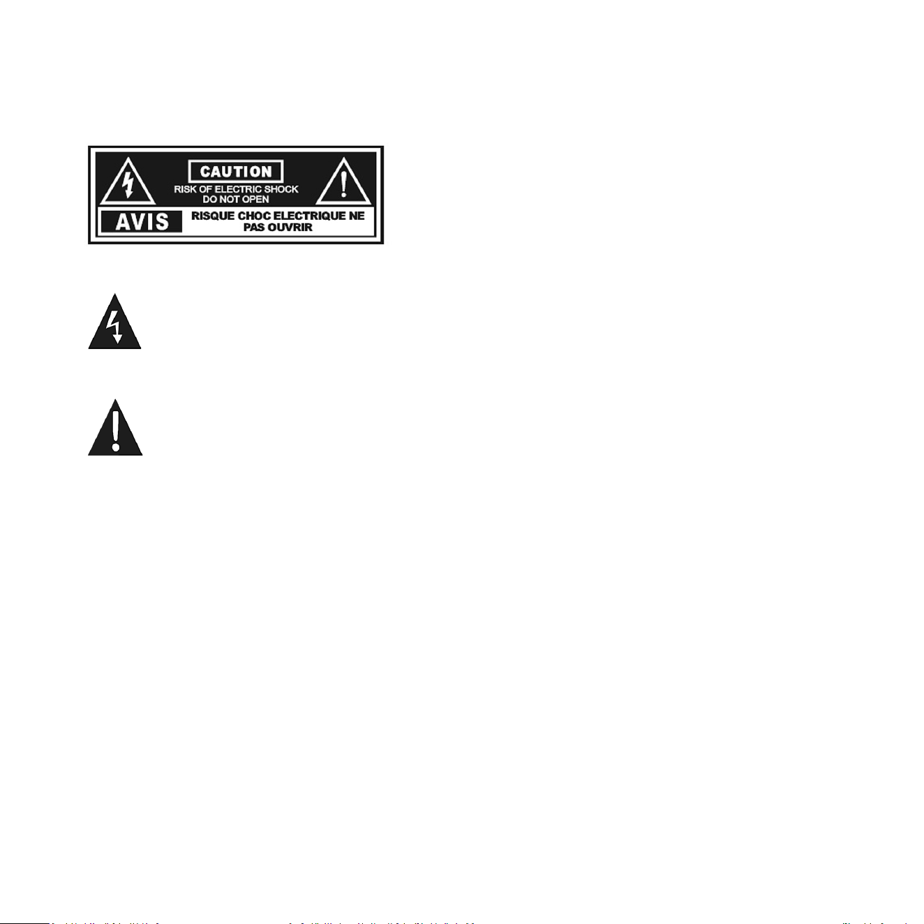
Cauon Marking Explanaon
The lightning ash with arrowhead symbol within an equilateral triangle is intended to alert the
user to the presence of un-insulated dangerous voltage within the product’s enclosure that may
be of sucient magnitude to constute a risk of electric shock to persons.
The exclamaon point within an equilateral triangle is intended to alert the user to the presence
of important operang and maintenance (servicing) instrucons in the literature accompanying
the appliance.

4
3
1 Read all of these instrucons.
2 Save these instrucons for future use.
3 Heed all warnings.
4 Follow all instrucons.
5 Do not use this apparatus near water.
6 Clean only with automove polish and micro ber cloth.
7 Install in accordance with the manufacturer’s instrucons.
8 Do not install near any heat sources such as radiators, heat registers, stoves or other apparatus (including
ampliers) that produce heat.
9 Do not defeat the safety purpose of the grounding-type plug. A grounding type plug has two blades and
a third grounding prong. The third prong is provided for your safety. If the provided plug does not t into
your outlet, consult and electrician for replacement of the obsolete outlet.
10 Protect the power cord from being walked on or pinched parcularly at plugs, convenience receptacles,
and the point where they exit from the apparatus.
11 Only use aachments/accessories specied by the manufacturer.
12 Use only with a cart, stand, tripod, bracket, or table specied by the manufacturer, or sold with the
apparatus. When a cart is used, use cauon when moving the cart/apparatus combinaon to avoid injury
from p-over.
13 Unplug this apparatus during lightning storms or when unused for long periods of me.
14 Refer all servicing to qualied service personnel. Servicing is required when the apparatus has been
damaged in any way, such as power-supply cord or plug is damaged, liquid has been spilled or objects
have fallen into the apparatus, the apparatus has been exposed to rail or moisture, does not operate
normally, or has been dropped.
Important Safety Instrucons

4
15 Minimum distances 10cm around the apparatus for sucient venlaon.
16 WARNING: The main plug/appliance coupler is used as the disconnect device. The disconnect device
shall remain readily operable.
17 CAUTION: To completely disconnect this product from the mains, disconnect the plug from the wall
socket outlet. The mains plug is used to completely interrupt the power supply to the unit and must be
within easy access by the user.
18 The equipment can be used at the maximum ambient temperature of 86 deg. F (30 deg. C).
19 Class I equipment, Protecve earthing is used as a safeguard, shall require connecon of equipment
protecve earthing conductor to the installaon protecve earthing conductor.
Cauon: Any changes or modicaons not expressly approved by the party responsible for compliance
could void the user’s authority to operate this equipment.
Warning
To reduce the risk of re or electric shock, do not expose this apparatus to rain or moisture.
The apparatus shall not be exposed to dripping or splashing and no objects lled with liquids, such as vases,
shall be placed on apparatus.
The mains plus is used as disconnect device. The mains plug of the apparatus should not be obstructed OR
should be easily accessed during intended use. To be completely disconnected from the power input, the
mains plug of the apparatus shall me disconnected from the mains.
An appliance with a protecve earth terminal should be connected to a mains outlet with a protecve
earth connecon.
Design Safety
These apparatus are supplied with a detachable mains cord. For 230V operaon a 2.5A fuse is ed in the
socket of the HT/1003 MKII and a 5A fuse is ed in the socket of the HT/1205 MKII, for 120V operaon a
4A fuse is ed for the HT/1003 MKII, and a 8A fuse is ed for the HT/1205 MKII. Should the fuse need
to be replaced use a similar rated fuse approved to ASTA or BSI 362 standards. Do not use without the fuse
cover in place. Replacement fuse covers are available from your distributor.
5
Aenon Explicaon Marquage
L’éclair avec le symbole de pointe de èche dans un triangle équilatéral est desné à alerter
l’ ulisateur de la présence de non isolée tension dangereuse à l’intérieur de l’enceinte du
produit qui peut être d’une ampleur susante pour constuer un risque d’électrocuon pour
les personnes.
Le point d’exclamaon dans un triangle équilatéral est desné à alerter l’ulisateur de la
présence d’instrucons dans la documentaon accompagnant l’appareil exploitaon et de
maintenance (entreen).
1 Lisez aenvement ces instrucons.
2 Conservez ces instrucons.
3 Respectez tous les averssements.
4 Suivez toutes les instrucons.
5 Ne pas uliser cet appareil près de l’eau.
6 Neoyez seulement avec du vernis automobile et ssu microbre.
7 Installer conformément aux instrucons du fabricant.
8 Ne pas installer près de sources de chaleur telles que des radiateurs, registres de chaleur, poêles ou
autres appareils (y compris les amplicateurs) qui produisent de la chaleur.
Informaons Importantes Relaves a la Securite

6
9 Ne pas contourner le disposif de sécurité de la prise de terre. Une che de terre a deux lames et une
troisième broche de mise à la terre. La troisième broche est fournie pour votre sécurité. Si la che fournie
ne rentre pas dans votre prise, consultez un électricien pour le remplacement de la prise obsolète.
10 Protégez le cordon d’alimentaon ne soit piéné ou pincé, en parculier au niveau des ches, des prises
de courant, et le point de sore de l’appareil.
11 Ulisez uniquement des xaons/accessoires spéciés par le fabricant.
12 Ulisez seulement avec un chariot, stand, trépied, support ou table spécié par le fabricant, ou vendu
avec l’appareil. Lorsque vous ulisez un chariot, soyez prudent lorsque vous déplacez l’ensemble
chariot/appareil pour éviter les blessures en cas de chute.
13 Débranchez cet appareil pendant un orage ou lorsqu’il est inulisé storsm pour de longues périodes
de temps.
14 Conez toute réparaon à un personnel qualié. Une réparaon est nécessaire lorsque l’appareil a été
endommagé de quelque façon que ce cordon d’alimentaon ou la che est endommagé, du liquide a
été renversé ou des objets sont tombés dans l’appareil, l’appareil a été exposé à rail ou à l’humidité, ne
fonconne pas normalement, ou a été échappé.
15 10cm distance minimale autour de l’appareil pour une aéraon susante.
16 AVERTISSEMENT: Le coupleur principal de prise/appareil est ulisé comme disposif de déconnexion.
Le disposif de déconnexion doit rester facilement ulisable.
17 ATTENTION: Pour déconnecter complètement ce produit du secteur, débranchez la che de la prise
murale. La che secteur sert à interrompre complètement l’alimentaon électrique de l’appareil et doit
être facilement accessible par l’ulisateur.
18 L’équipement peut être ulisé à une température ambiante maximale de 30 deg. C (86 deg. F).
19 L’équipement de classe I, la mise à la terre de protecon est ulisée comme protecon, doit nécessiter
la connexion du conducteur de mise à la terre de protecon de l’équipement au conducteur de mise à la
terre de protecon de l’installaon.
Aenon: Tout changement ou modicaon non expressément approuvés par la pare responsable de la
conformité pourraient annuler l’autorité de l’ulisateur à uliser cet équipement.

7
Averssement
Cet arcle est lourd. Pour éviter tout risque de blessure, prendre soin lors de la manipulaon.
L’ appareil ne doit pas être exposé à des éclaboussures et aucun objet rempli de liquide, comme des vases,
ne doit être placé sur l’appareil.
Les conduites Plus est ulisé comme disposif de déconnexion. La che de l’appareil ne doit pas être
obstruée OU doit être facilement accessible pendant l’ulisaon. Pour être complètement déconnecté de
l’alimentaon électrique, le cordon d’alimentaon de l’appareil doit me débranché.
Un appareil avec une borne de terre doit être branché sur une prise de courant en étant relié à la terre.
Sécurité Design
Ces appareils sont fournis avec un cordon d’alimentaon amovible. Pour un fonconnement en 230 V, un
fusible de 2,5 A est installé dans la prise du HT/1003 MKII et un fusible de 5 A est installé dans la prise du
HT/1205 MKII, pour un fonconnement en 120 V, un fusible de 4 A est installé pour le HT/1003 MKII et un
fusible de 8 A est adapté pour le HT/1205 MKII. Si le fusible doit être remplacé, ulisez un fusible de calibre
similaire approuvé selon les normes ASTA ou BSI 362. Ne pas uliser sans le couvercle du fusible en place.
Des couvre-fusibles de remplacement sont disponibles auprès de votre distributeur.
FCC STATEMENT
This device complies with Part 15 of the FCC Rules. Operaon is subject to the following two condions:
(1) This device may not cause harmful interference, and
(2) This device must accept any interference received, including interference that may cause
undesired operaon.
NOTE: This equipment has been tested and found to comply with the limits for a Class B digital Device, pursuant to Part 15 of the
FCC Rules. These limits are designed to provide reasonable protecon against harmful interference in a residenal installaon.
This equipment generates, uses and can radiate radio frequency energy and, if not installed and used in accordance with the
instrucons, may cause harmful interference to radio communicaons. However, there is no guarantee that the interference will
not occur in a parcular installaon. If this equipment does cause harmful interference to radio or television recepon, which can
be determined by turning the equipment o and on, the user is encouraged to try and correct the interference by one or more of
the following measures:
Reorient or relocate the receiving antenna.
Increase the separaon between the equipment and receiver.
Connect the equipment into an outlet on a circuit dierent from that to which the receiver is connected.

87
Consult the dealer or an experienced radio/TV technician for help.
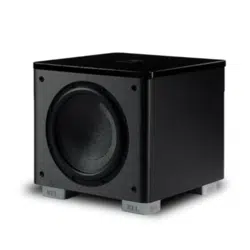
Dear REL Owner,
REL are incredibly excited about these newer HT models. Whilst the originals were exceponally well-received
by reviewers and customers alike, we had learned so much from our development of the latest Serie S and
Serie T/x models that we felt certain we could eect real improvements if we applied some of these to our HT’s.
WOW! The improvements turned out to be truly remarkable. Drivers, amps and lters were upgraded
across the line. The result delivers far higher output levels, greater dynamics (the dierence between loud
and so) a more relaxed, composed presence like much more expensive units deliver and a huge upgrade
in style, design and t and nish.
The nal touch is that these are far beer developed for music applicaons than were the originals. And
they visually integrate perfectly with tradional RELs in HT/3D applicaons.
HT/1205 MKII meanwhile beneed from a full 6 dB (50% louder) increase in output taking this into the realm
of units cosng well over $1,000/£. Incredible output, delivered with greater explosiveness on special eects,
but beer able to deal with musical material means a unit that has evolved signicantly for the beer.
And then there’s the lile HT/1003 MKII; sporng a 10+ dB increase in output with all the same benets
that aach to our dearer models it is the most dramacally updated. It no longer represents the lile
brother; rather it is idencal in quality to our best-selling HT/1205 MKII in a smaller chassis that will allow it
to t where larger models can’t.
Thank You and Enjoy, we grew to love this new range as it evolved before our eyes and ears.
Best, J
John Hunter
Lead Designer,
REL Acouscs Limited
Dear Friend and Valued Customer

9
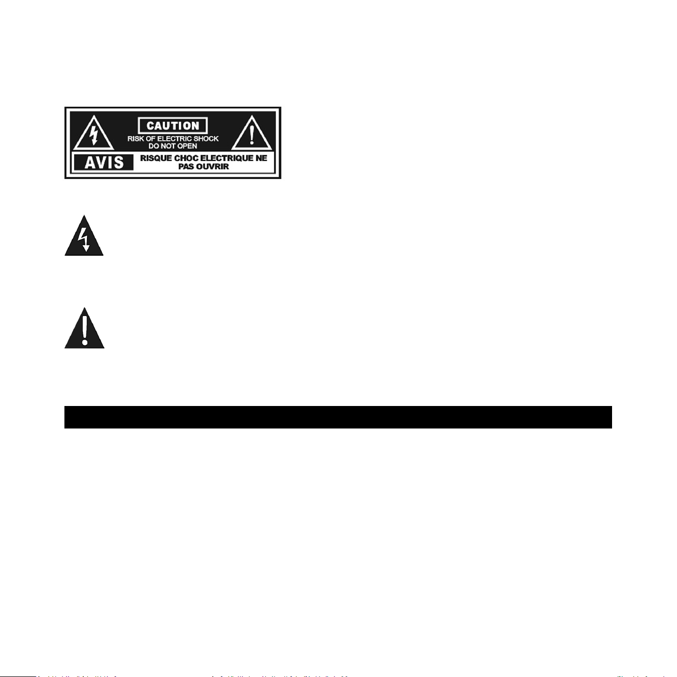
1 Power Pilot Light: Power On/O indicator.
2 Standby/ Always On Switch: Used to enable standby mode
3 Phase: Used to set phase 0-180 degrees.
4 Crossover: Used to adjust crossover frequency. Variable between 30-200Hz.
5 Level: Volume control for Input.
6 RCA Output: Used to connect or “daisy chain” another REL in tandem.
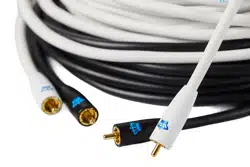
7 Le & Right Channel Low-Level RCA Input: Used to connect low-level signals to the sub-bass system
from the output of a preamplier, integrated amplier or receiver.
(For home cinema use, use .1/LFE input)
8 Mains Select Switch: Slide switch used to set input AC between 120VAC and 230VAC.
9 Power On/O Switch: Use to turn unit on or o.
10 IEC Mains Socket: Fused mains (AC) input socket that accepts detachable power cord.
REL HT/MKII Rear Panel Connecon Legend
10
8 9 10
1
2
3
4
5
6
7

11
Always switch o your system before disconnecng any wires.
To simplify and to increase the versality of connecng, the HT/MKII models have two low-level RCA
inputs. This is to facilitate ability to use with AV surround sound systems, two-channel stereo systems and
powered speakers.
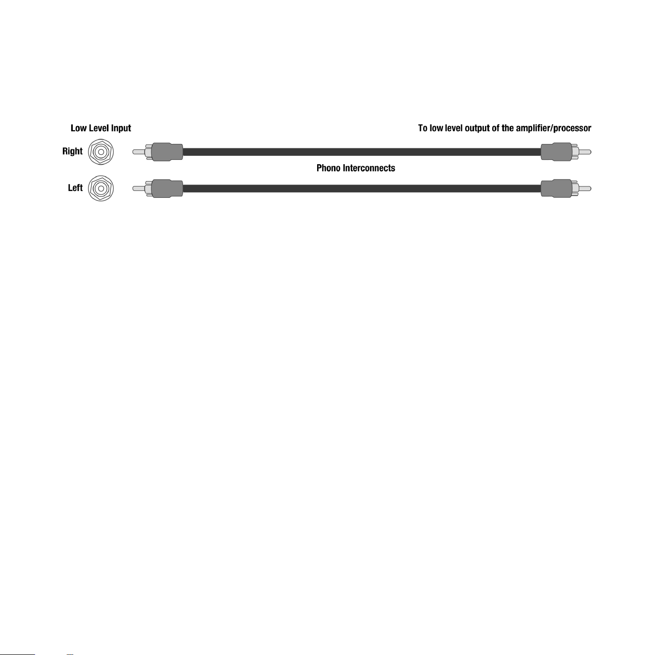
Low-Level Inputs
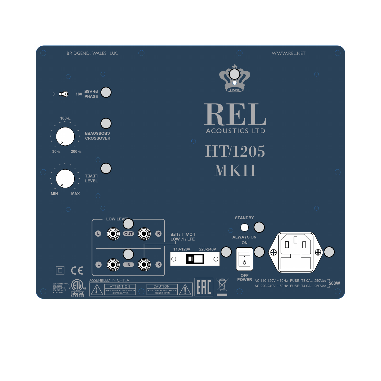
.1/LFE Input
There is a single RCA jack labeled .1/LFE for LFE connecon to a processor. Plug one end of the RCA to RCA
cable into the .1/LFE jack of the REL and the other end into the SUB OUT Jack of your processor.
Stereo L/R Input
The dual RCA jacks can be used for stereo low-level connecon to the output of a stereo processor source or
powered speakers. When using stereo inputs, plug one end of the RCA to RCA cables into both of the LOW
LEVEL INPUT jacks of the REL and the other end into the le and right channel output of your preamplier.
The upper frequency amplicaon of these inputs can be limited using the CROSSOVER control. This
CROSSOVER control is labeled 30Hz at its minimum. Rarely should the CROSSOVER control be set to it’s
maximum 200Hz setpoint when using either LFE or stereo inputs.
The RCA inputs have corresponding output connecons so that mulple RELs can be run in parallel by
connecng the OUT of one the IN of the next. This is what we refer to as “daisy chaining”.
Phase Switch
The phase control on a REL has two posions, 0 and 180. One of these posions will set the REL in phase
with the speakers, and one will set it out of phase. The labels 0 and 180 are just labels and tell us nothing
about the rest of the system, only if the REL is working with the speakers or not. Whichever posion results
in the loudest and fullest sub bass, is the correct posion.
We want the REL to work in harmony with the speakers, reinforcing bass, not cancelling it. In other words,
we want the drivers in the speakers and the REL to move forward at the same me and move backward at
the same me. When this happens, it results in an increase in sub bass volume and the pressurizaon in the
room and they are in phase. The opposite is if the speakers and REL are working against each other causing
cancelaon of low bass. We call this out of phase.
Connecng Up
12
With the REL HT/MKII, there are two basic ways to connect and setup. The rst is a single channel input
from the sub out of a theater or power speaker system. In this case a single RCA cable is needed. The second
is a stereo input from a stereo preamp or powered speaker system. Here there will be the need for two RCA
cables. In both cases the user can set the upper frequency limit using the CROSSOVER control.
Connecng and Seng Up
Place in desired posion. While your REL has been designed to be extremely easy to posion and achieve
excellent results, careful placement along the same wall as the screen will yield improvements. Listen for
increases in deep bass output as well as precision of bass notes when seng up.
Theater connecon (Sub Out connecton)
Connect RCA cable from Sub Out of theater processor to LFE input of HT/MKII.
• Adjust CROSSOVER control to 30Hz (minimum).
• Adjust LEVEL control to 1/4 of the rotaon up from minimum seng.
• Plug in AC cord.
• Power on with switch next to AC input.
• Set toggle above power switch to ALWAYS ON.
• Fine tune LEVEL control using a known powerful .1 chapter to make sure your seng is not too high or
damage can occur.
• Adjust CROSSOVER control lower to eliminate upper bass boom.
• DO NOT TURN CROSSOVER UP PAST 1/2 the rotaon. Doing so is unnecessary and may result in damage
to the driver.
REL Set-Up Made Simple
13
Stereo connecon (Powered Speaker connecon)
Connect RCA from output to right input for mono or both le and right for stereo.
• Adjust CROSSOVER control to 30Hz (minimum).
• Adjust LEVEL control to 1/4 of the rotaon up from minimum seng.
• Plug in AC cord.
• Power on with switch next to AC input.
• Set toggle above power switch to ALWAYS ON.
• Fine tune LEVEL control to blend with powered speakers.
• Fine tune CROSSOVER control to blend.
• Note that CROSSOVER and LEVEL become inverse. Meaning, as you turn up the CROSSOVER, you will
need to turn down the LEVEL.
• DO NOT TURN CROSSOVER UP PAST 1/2 the rotaon. Doing so is unnecessary and may result in
damage to the driver.
• Place carefully: While your REL has been designed to be extremely easy to posion and achieve
excellent results, careful placement along the same wall as the screen will yield improvements.
Listen for increases in deep bass output as well as precision of bass notes when seng up
Phase Orientaon
Once connected, we need to adjust for phase. This may be the single most crical step, and because it really
is quite simple, it is oen over-thought. Keep in mind; the right phase is whichever posion is the loudest or
fullest. While playing music with true low bass, adjust the crossover to a point where the REL and the speaker
are sure to share frequencies at 50Hz on the crossover control, or slightly higher for smaller speakers. At
this point turn the LEVEL control up so that both the REL and speaker are roughly equal in volume and then

14
switch, using the phase switch, from “0” to “180” phase posions. Again, whichever posion is loudest or
fullest is the correct posion. That is, when the posion is working in harmony with your main speakers,
reinforcing bass, not canceling it.
Crossover and Level Sengs:
To determine the crossover point, take the volume of the REL (using the Level control) all the way down,
and put the crossover to 1/4 of the rotaon. At this point, bring the REL’s volume back up slowly to the
point where you have achieved a subtle balance, i.e. the point at which you can just hear the HT/MKII even
with the main speakers playing. First, bring the crossover point up unl it is obviously too high; now gently
reduce frequency to the appropriate seng. For all intents and purposes, this is the correct crossover point.
Once this stage has been reached, subtle changes to volume and crossover may be accomplished to provide
the last bit of complete and seamless integraon. With that, set-up is complete
Hint: There may be a tendency to set the crossover point too high and the volume of the Sub-Bass System
too low when rst learning how to integrate a REL with the system, the fear being one of overwhelming the
main speakers with bass. In making this common error, the resulng set-up will be lacking in bass depth and
dynamics. The proper crossover point and volume seng will increase overall dynamics, allow for extended
bass frequencies, and improve soundstage properes. Note, volume adjustments may need to be made to
oset the eects of crossover changes. In general, when selecng a lower crossover point, more volume may
need to be applied. Higher crossover frequencies will generally necessitate less gain
Running In
Care taken during run in will be rewarded by many years of pleasurable use. Both the electronics and the
drive unit will benet from an inial period of carefully controlled use. Possible damage may be sustained
by running in the unit at too high a volume seng over an extended period. On the other hand, by taking a
lile care over this inial period, about 24 hours of actual use, a longer life with a higher potenal eventual
performance is assured.
Care and Polishing
The cabinets are best maintained by using only a damp cloth on the vinyl. For the top, please use
automobile polish made by reputable manufacturers. Our favorites are those made by Meguiars and
Mother’s. If objects are to be placed upon the top, it is advisable to use a small mat to protect the surface
and to avoid the risk of rales.

The HT/MKII employs an advanced lter circuit which provides exceponal performance when coupled to
the rest of the signal chain of the Sub-Bass System.
The amplier is inherently stable and will retain its characteriscs over very long periods of me – important
in a unit designed for an exceponally long working life. These ampliers are designed to withstand reasonable
abuse and overloads. If in doubt, please contact your dealer.
We believe that the importance of the electronics, cabinet and drivers being designed to work in harmony is
paramount. This belief allows HT/MKII to achieve the highest possible level of delity.
Overload Protecon
All REL Sub-Bass Systems are designed as true sub bass speakers. They are designed to reproduce those
exceponally deep notes that are felt as well as heard. This it will aempt to do at whatever volume level
you set. If set too high no damage should result because the built-in electronics will limit the cone movement.
This electronic control is called Set-Safe™. It constantly and instantaneously monitors the output from the
power amplier and is totally transparent in operaon unl required. This means it has absolutely no eect
on the sound quality of your REL unl an overload is detected.
Ordinarily an overload would cause the power amplier to go into clipping with resultant loss of control over
the drive unit. This can cause drive unit damage, and always sounds nasty. Set-Safe™ detects the point of
incipient clipping and gently so-clips the waveform of the signal to ensure actual clipping does not occur.
This is a necessarily simplied descripon of what actually happens, but in eect, Set-Safe™ controls the
amplier and ensures there is minimum risk of amplier and driver damage caused by over-driving.
A thermal overload device is ed to all HT/MKII Sub-Bass Systems. If the unit is deliberately over-driven
this device will sense the temperature rise and cut the output; recovery me is approximately ve minutes.
If this happens, it is a warning that the unit is being over-driven and the volume level control should be
reduced to a safe level.
Although everything possible has been done to minimize risk of thermal overload failure, there can be
no defense against those individuals who deliberately abuse the device. Such damage is NOT covered by
warranty. Please remember your REL is there to supplement your main system, not overwhelm it!
15
Technical
16
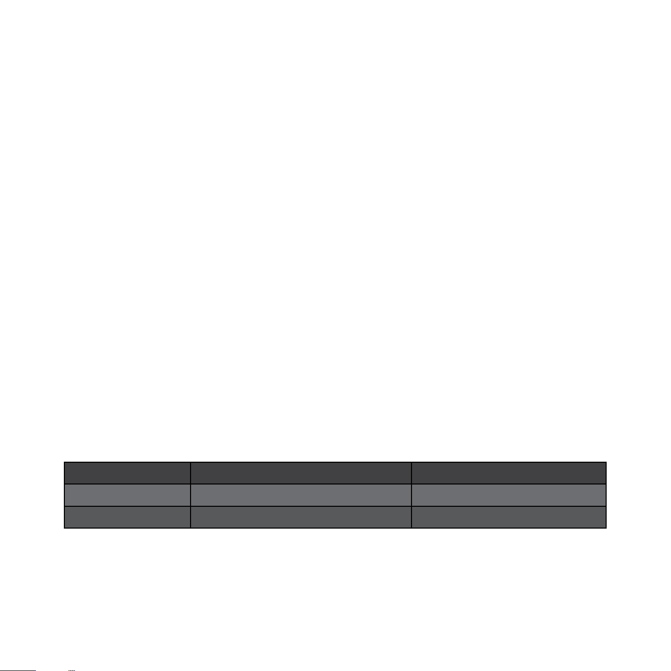
Power Saving Eciency
All REL Sub-Bass System designs ulize a true Power On-O switch that aords the owner the ability to
turn o their unit completely, without having to unplug the A/C mains cord. When a REL Sub-Bass System
is switched o using the Power On-O switch on the rear panel it draws ZERO power.
In addion to the power switch there is an ALWAYS ON/STANDBY mode switch that has two posions.
Up engages the STANDBY circuit and down keeps the unit always on. In addion to the power switch there
is an ALWAYS ON/STANDBY mode switch has two posions. Up engages the STANDBY circuit and down keeps
the unit always on.
The HT/MKII features a standby mode that is enabled when the mode switch on the rear of the unit is set to
the “STANDBY” posion. In this mode, the input signal is constantly monitored for audio acvity. If not audio
informaon is detected over a period of 30 minutes, the unit will enter a low power standby mode in which
less power is consumed. When input signal acvity is detected, the unit resumes normal operaon. By using
the standby mode, you can ensure that there is no unnecessary power draw when the unit is not in use.
Note: Due to variaons in program material, it is impossible to produce a perfectly reliable standby circuit.
Bass rich music or eects will consistently trigger our standby circuit whilst content that is low in volume and
possesses lile or no bass cannot be relied upon to trip the standby funcon.
Alternavely, the user has the opon to leave the unit in the normal operaon mode at all mes by selecng
the “ALWAYS ON” posion of the power mode switch. Leaving a REL on produces the best sonic performance
and the most reliable operaon. In this mode, the unit will not enter standby regardless of whether or not
there is acvity at the input. Using this seng ensures that the HT/MKII is ready to react instantaneously to
bass transients, whether in music or lms.
Model Power Draw at Standby Power Draw at Idle
HT/1205 MKII > 0.5 Was 13 Was
HT/1003 MKII > 0.5 Was 10 Was

Type: Closed box, front ring woofer
Drive Unit: 12 in., carbon ber reinforced cone with inverted carbon ber center cap
In Room
Frequency Extension: -6dB at 22Hz in Room
Input Connectors: Low Level stereo RCA, LFE RCA
Output Connectors: Low Level stereo RCA, LFE RCA
Power Output: 500 was (RMS)
Phase Switch: 2 - posion, 0 or 180 degrees
Amplier Type: Class D
Fully Electronic with SET-SAFE: Yes
DC Fault: Yes
Output Short: Yes
Mains Input Voltage: 220-240 volts, 110-120 volts for certain markets
Fuses: 4 Amp semi delay 230V operaon
8 Amp semi delay 115V operaon
Dimensions
W x H x D, Inc. Feet: Including feet and rear panel controls
16.25 x 15.25 x 17.25 in., (413 x 387 x 438 mm)
Net Weight: 43.2 lbs. (19.6 kg)
Shipping Weight: 51 lbs. (23 kg)
Finish: Horizontally Oriented Line Grained Composite,
15 mm Top Plate, nished in 5 coats of hand-rubbed high gloss lacquer
Supplied Accessories
Mains Lead: Included
Users Setup guide: Online
17
HT/1205 MKII Specicaons
Type: Closed box, front ring woofer
Drive Unit: 10 in., carbon ber reinforced cone with inverted carbon ber center cap
In Room
Frequency Extension: -6dB at 24Hz in Room
Input Connectors: Low Level stereo RCA, LFE RCA
Output Connectors: Low Level stereo RCA, LFE RCA
Power Output: 300 was (RMS)
Phase Switch: 2 - posion, 0 or 180 degrees
Amplier Type: Class D
Fully Electronic with SET-SAFE: Yes
DC Fault: Yes
Output Short: Yes
Mains Input Voltage: 220-240 volts, 110-120 volts for certain markets
Fuses: 2.5 Amp semi delay 230V operaon
5 Amp semi delay 115V operaon
Dimensions
W x H x D, Inc. Feet: Including feet and rear panel controls
14.25 x 13.25 x 15.25 in., (362 x 343 x 387 mm)
Net Weight: 34.2 lbs. (15.5 kg)
Shipping Weight: 41 lbs. (18.6 kg)
Finish: Horizontally Oriented Line Grained Composite,
15 mm Top Plate, nished in 5 coats of hand-rubbed high gloss lacquer
Supplied Accessories
Mains Lead: Included
Users Setup guide: Online
In the interest of product development, REL Acouscs Limited reserve the right to vary these specicaons without noce
18
HT/1003 MKII Specicaons

REL Acouscs Limited
North Road, Bridgend industrial Estate . Bridgend, CF31 3TP . United Kingdom
Telephone: +44 (0)1 656 768 777 . Fax: +44 (0) 1 656 766 093
Web: www.rel.net