Installation & Operation Manual
Models: 400 - 500
Series 100 & 101
and 650 - 1000
Series 110 & 111
is manual must only be used
by a qualied heating installer
/ service technician. Read all
instructions, including this
manual and the Knight XL
Service Manual, before installing.
Perform steps in the order given.
Failure to comply could result in
severe personal injury, death, or
substantial property damage.
⚠ WARNING
Save this manual for future reference.
100383073_2000837361_Rev E

2
Contents
Hazard denitions
e following dened terms are used throughout this manual to bring attention to the presence of hazards of various risk levels
or to important information concerning the life of the product.
⚠ DANGER
⚠ WARNING
⚠ CAUTION
CAUTION
NOTICE
DANGER indicates an imminently hazardous situation which, if not avoided, will result in death or serious
injury.
WARNING indicates a potentially hazardous situation which, if not avoided, could result in death or serious
injury.
CAUTION indicates a potentially hazardous situation which, if not avoided, may result in minor or moderate
injury.
CAUTION used without the safety alert symbol indicates a potentially hazardous situation which, if not
avoided, may result in property damage.
NOTICE indicates special instructions on installation, operation, or maintenance that are important but not
related to personal injury or property damage.
HAZARD DEFINITIONS .................................................. 2
PLEASE READ BEFORE PROCEEDING ..................... 3
THE KNIGHT XL -- HOW IT WORKS ......................... 4-6
RATINGS .......................................................................... 7
PRODUCT SUMMARY .................................................... 8-9
1. DETERMINE BOILER LOCATION
Provide Air Openings to Room ........................................ 10
Flooring and Foundation ................................................. 12
Residential Garage Installation ........................................ 12
Vent and Air Piping .......................................................... 12
Prevent Combustion Air Contamination ........................... 12
Corrosive Contaminants and Sources ............................. 13
Using an Existing Vent System to Install a New Boiler ... 13
Removing a Boiler from Existing Common Vent .............. 14
2. PREPARE BOILER
Remove Boiler from Wood Pallet ..................................... 15
Gas Conversions ......................................................... 15-16
3. GENERAL VENTING
Direct Venting Options ..................................................... 17
Install Vent and Combustion Air Piping ........................... 18
Requirements for Installation in Canada .......................... 19
Sizing ............................................................................... 19
Min./Max. Combustion Air & Vent Piping Lengths ............ 19
Materials ............................................................................ 20
Optional Room Air ............................................................ 21
PVC/CPVC .................................................................. 21-22
Polypropylene ................................................................... 23
Stainless Steel Vent ......................................................... 24
4. SIDEWALL DIRECT VENTING
Vent/Air Termination - Sidewall ................................... 26-29
Determine Location ................................................ 26-28
Prepare Wall Penetrations ..................................... 28-29
Multiple Vent/Air Terminations ......................................... 29
Sidewall Termination - Optional Concentric Vent ....... 30-32
5. VERTICAL DIRECT VENTING
Vent/Air Termination - Vertical .................................... 33-34
Determine Location ..................................................... 33
Prepare Roof Penetrations ......................................... 34
Multiple Vent/Air Terminations ......................................... 34
Vertical Termination - Optional Concentric Vent ......... 35-36
Alternate Vertical Concentric Venting ......................... 37-38
6. OUTDOOR INSTALLATIONS ............................... 39-40
7. HYDRONIC PIPING
System Water Piping Methods ......................................... 41
Low Water Cuto Device ................................................. 41
Chilled Water System ....................................................... 41
Freeze Protection ............................................................. 41
General Piping Information .............................................. 41
Near Boiler Piping Components ....................................... 43
Circulator Sizing ............................................................... 44
Near Boiler Piping Connections ....................................... 44
8. GAS CONNECTIONS
Connecting Gas Supply Piping ........................................ 51
Natural Gas ...................................................................... 52
Pipe Sizing for Natural Gas ........................................ 52
Natural Gas Supply Pressure Requirements ............. 52
Propane Gas .................................................................... 52
Pipe Sizing for Propane Gas ...................................... 52
Propane Supply Pressure Requirements ................... 52
Check Inlet Gas Supply ................................................... 53
Gas Pressure ................................................................... 54
Gas Valve Replacement .................................................. 54
9. FIELD WIRING
Line Voltage Connections ................................................ 55
Low Voltage Connections ................................................ 55
Wiring of the Cascade ...................................................... 57
10. CONDENSATE DISPOSAL
Condensate Drain ............................................................ 59
11. START-UP ............................................................ 60-69
12. OPERATING INFORMATION
General ............................................................................. 70
Cascade ........................................................................... 73
Sequence of Operation .................................................... 74
Knight XL Control Module ................................................ 75
13. MAINTENANCE
Maintenance and Annual Startup ..................................... 76
14. DIAGRAMS
Wiring Diagram ........................................................... 81
Ladder Diagram ......................................................... 82
Revision Notes .................................................. Back Cover
Installation & Operation Manual
Please read before proceeding
Installer – Read all instructions, including
this manual and the Knight XL Service
Manual, before installing. Perform steps in
the order given.
User – is manual is for use only by
a qualified heating installer/service
technician. Refer to the User’s Information
Manual for your reference.
Have this boiler serviced/inspected by
a qualied service technician, at least
annually.
Failure to comply with the above could
result in severe personal injury, death or
substantial property damage.
Failure to adhere to the guidelines on this
page can result in severe personal injury,
death, or substantial property damage.
When servicing boiler –
• To avoid electric shock, disconnect electrical supply
before performing maintenance.
• To avoid severe burns, allow boiler to cool before
performing maintenance.
Boiler operation –
• Do not block ow of combustion or ventilation air to
the boiler.
• Should overheating occur or gas supply fail to shut o,
do not turn o or disconnect electrical supply to
circulator. Instead, shut o the gas supply at a location
external to the appliance.
• Do not use this boiler if any part has been under water.
e possible damage to a ooded appliance can be
extensive and present numerous safety hazards. Any
appliance that has been under water must be replaced.
• e installer must verify that at least one carbon monoxide
alarm has been installed within a residential living space
or home following the alarm manufacturer’s instructions
and applicable local codes before putting the appliance
into operation
Boiler water –
• oroughly ush the system to remove debris. Use
an approved pre-commissioning cleaner (see Start-Up
Section), without the boiler connected, to clean the
system and remove sediment. e high eciency heat
exchanger can be damaged by build-up or corrosion due
to sediment.
NOTE: Cleaners are designed for either new systems or
pre-existing systems. Choose accordingly.
Freeze protection uids –
• NEVER use automotive antifreeze. Use only inhibited
propylene glycol solutions, which are specically
formulated for hydronic systems. Ethylene glycol is
toxic and can attack gaskets and seals used in hydronic
systems.
When calling or writing about the boiler
– Please have the boiler model and serial
number from the boiler rating plate.
Consider piping and installation when
determining boiler location.
Any claims for damage or shortage in
shipment must be led immediately
against the transportation company by the
consignee.
Factory warranty (shipped with unit) does
not apply to units improperly installed or
improperly operated.
3
If the information in this manual is not
followed exactly, a re or explosion may
result causing property damage, personal
injury or loss of life.
is appliance MUST NOT be installed in
any location where gasoline or ammable
vapors are likely to be present.
WHAT TO DO IF YOU SMELL GAS
• Do not try to light any appliance.
• Do not touch any electric switch; do
not use any phone in your building.
• Immediately call your gas supplier
from a near by phone. Follow the
gas supplier’s instructions.
• If you cannot reach your gas supplier,
call the re department.
• Installation and service must be
performed by a qualied installer,
service agency, or the gas supplier.
⚠ WARNING
NOTICE
⚠ WARNING
⚠ WARNING
⚠ WARNING
DO NOT install units in rooms or
environments that contain corrosive
contaminants (see Table 1A). Failure to
comply could result in severe personal
injury, death, or substantial property
damage.
⚠ WARNING
e California Safe Drinking Water and
Toxic Enforcement Act requires the
Governor of California to publish a list of
substances known to the State of California
to cause cancer, birth defects, or other
reproductive harm, and requires businesses
to warn of potential exposure to such
substances.
is product contains a chemical known to
the State of California to cause cancer, birth
defects, or other reproductive harm. is
boiler can cause low level exposure to some
of the substances listed in the Act.

4
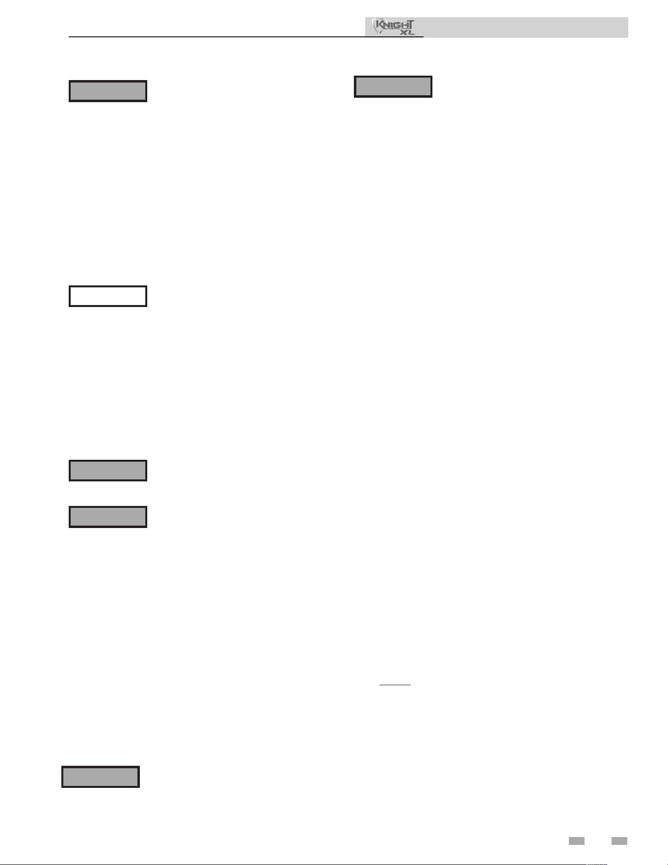
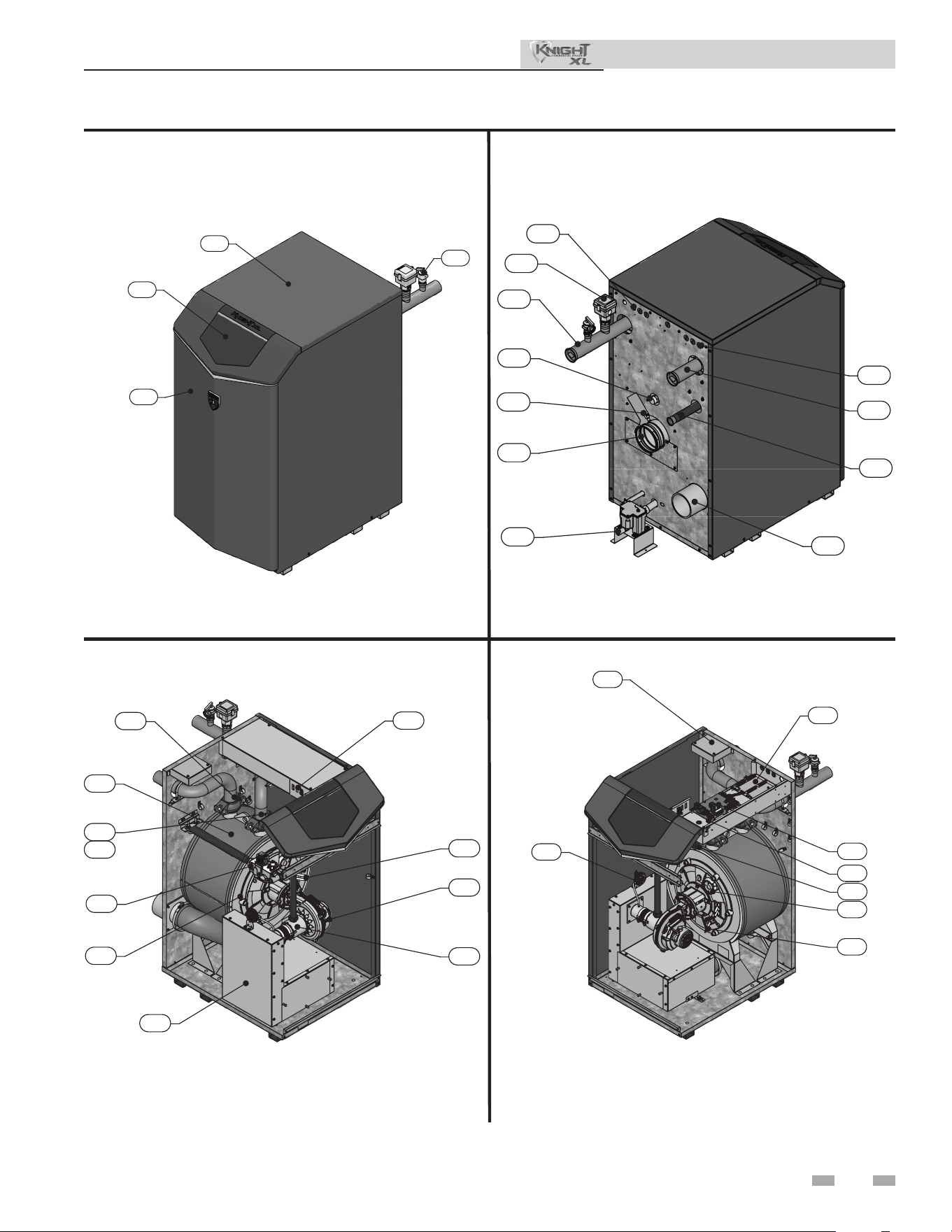
The Knight XL - How it works...
1. Stainless steel heat exchanger
Allows system water to ow through specially designed
coils for maximum heat transfer, while providing protection
against ue gas corrosion. e coils are encased in a jacket that
contains the combustion process.
2. Combustion chamber access cover
Allows access to the combustion side of the heat exchanger
coils.
3. Blower
e blower pulls in air and gas through the venturi.
Air and gas mix inside the blower and are pushed into the
burner, where they burn inside the combustion chamber.
4. Gas valve
e gas valve senses the negative pressure created by the
blower, allowing gas to ow only if the gas valve is powered and
combustion air is owing.
5. Venturi
e venturi controls air and gas ow into the burner.
6. Flue gas sensor (limit rated)
is sensor monitors the ue gas exit temperature. e
control module will modulate and shut down the boiler if the
ue gas temperature gets too hot. is protects the ue pipe from
overheating.
7. Boiler outlet temperature sensor (housed with the
high limit sensor)
is sensor monitors boiler outlet water temperature (system
supply). If selected as the controlling sensor, the control
module adjusts boiler ring rate so the outlet temperature is
correct.
8. Boiler inlet temperature sensor
is sensor monitors return water temperature (system
return). If selected as the controlling sensor, the control
module adjusts the boiler ring rate so the inlet temperature is
correct.
9. Temperature and pressure gauge (eld installed, not
shown)
Monitors the outlet temperature of the boiler as well as the
system water pressure.
10. Electronic display
Digital controls with SMART TOUCH screen technology, full
color display, and an 7" user interface screen.
11. Flue pipe adapter
Allows for the connection of the PVC vent pipe system to the
boiler.
12. Burner (not shown)
Made with metal ber and stainless steel construction, the
burner uses pre-mixed air and gas and provides a wide range of
ring rates.
13. Water outlet (system supply)
A 2" (Models 400 - 800) or 2.5" (Model 1000) water connection
that supplies hot water to the system.
14. Water inlet (system return)
A 2" (Models 400 - 800) or 2.5" (Model 1000) copper water
connection that returns water from the system to the heat
exchanger.
15. Gas connection pipe
readed pipe connection of 1" or 1 1/4" (depending on the
model). is pipe should be connected to the incoming gas
supply for the purpose of delivering gas to the boiler.
16. SMART TOUCH Control Module
e SMART TOUCH Control responds to internal and
external signals and controls the blower, gas valve, and pumps
to meet the heating demand.
17. Air intake adapter
Allows for the connection of the PVC air intake pipe to the
boiler.
18. High voltage junction box
e junction box contains the connection points for the line
voltage power and all pumps.
19. Boiler drain port
Location from which the heat exchanger can be drained.
20. Low voltage connection board
e connection board is used to connect external low voltage
devices.
21. Low voltage wiring connections (knockouts)
Conduit connection points for the low voltage connection
board.
22. Condensate drain connection
Connects the condensate drain line to a 1/2" PVC connection.
23. Access cover - front
Provides access to the gas train and the heat exchanger.
24. Ignition electrode
Provides direct spark for igniting the burner.
25. Flame inspection window
e quartz glass window provides a view of the burner surface
and ame.
26. Relief valve
Protects the heat exchanger from an over pressure condition.
e relief valve provided with the unit is set at 50 PSI.
27. Flame sensor
Used by the control module to detect the presence of burner
ame.
28. Line voltage wiring connections (knockouts)
Conduit connection points for the high voltage junction box.
29. Top panel
Removable panel to gain access to the internal components.
30. Power switch
Turns 120 VAC ON/OFF to the boiler.
31. Airbox
e air box houses the combustion air lter.
32. Air pressure switch (400 and 800 models only)
e air pressure switch detects blocked ue/inlet conditions.
break the control circuit, shutting the boiler down.
33. Pump relays
e pump relay is used to connect the boiler, system and
DHW pumps.
34. Transformer
e transformer provides 24V power to the integrated control.
35. Highlimitsensor(housedwiththeoutlettemperature
sensor)
Device that monitors the outlet water temperature. If the
temperature exceeds its setting, the integrated control will break
the control circuit, shutting the boiler down.
36. AirFilter(notshown)
e air lter prevents dirt and debris from entering the burner.
37. FlowSwitch
e ow switch is a safety device that ensures ow through
the heat exchanger during operation. is appliance is low
mass and should never be operated without ow. e ow
switch makes contact when ow is detected and allows the unit
to operate. If ow is discontinued during oepration for any
reason, the ow switch will break the control circuit and the
unit will shut down.
Installation & Operation Manual
Front View - Model 400
4
1
2
31
3
24
30
5
8
7
35
Left Side (inside unit) - Model 400
18
33
20
16
25
27
34
32
Right Side (inside unit) - Model 400
The Knight XL - How it works... (continued)
Rear View - Model 400
5
Model 400 - 500
10
29
23
26
21
13
11
14
15
28
37
19
17
22
6
Installation & Operation Manual
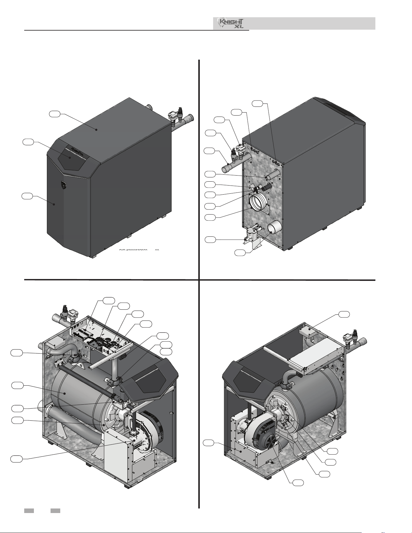
6
The Knight XL - How it works...
DIR #2000582923 00
DI
R
#2
00
05
82
92
3
0
0
DIR #200058292300
29
10
23
Front View - Model 1000
DIR #2000582932 00
1
2
4
5
20
33
30
34
7
8
35
16
Rear View - Model 1000 Left Side (inside unit) - Model 1000
Left Side (inside unit) - Model 1000
Model 650 - 1000
DIR #2000582924 00
21
26
13
14
15
11
22
19
28
6
17
37
DIR #2000582937 00
31
18
24
27
3
25
Installation & Operation Manual
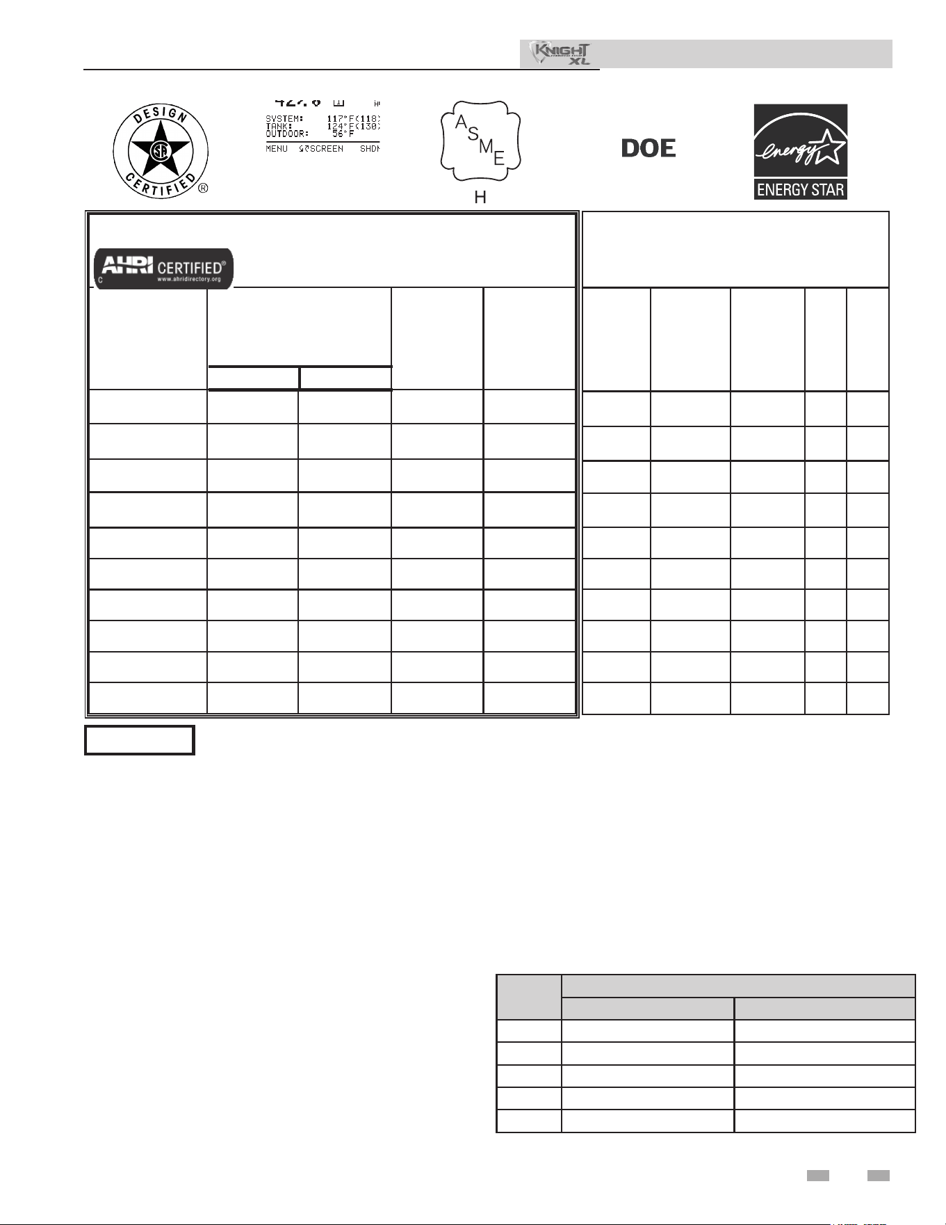
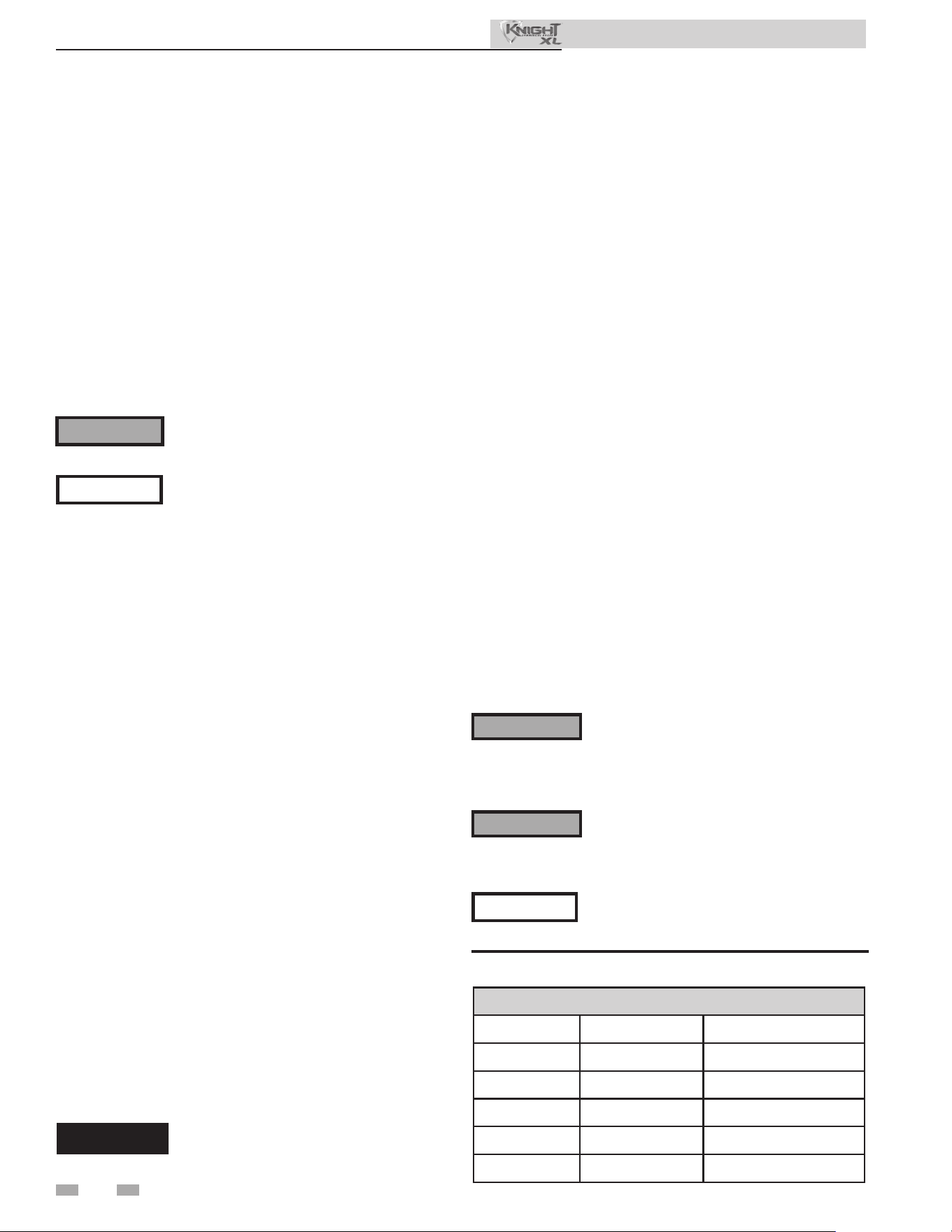
Ratings
7
NOTICE
Knight XL Boiler
AHRI Rating
Model Number
Note: Change “N” to
“L” for L.P. gas models.
Input
MBH
(Note 2)
Min Max
Gross
Output
MBH
(Note 1)
Net
AHRI
Ratings
Water,
MBH
(Note 2)
KBX0400(N,L) 39.9 399 387 337
KBX0500(N,L) 50 500 485 422
KBX0650(N,L) 65 650 631 549
KBX0800(N,L) 80 800 776 675
KBX1000(N,L) 99.9 999 969 843
KBX0400-O(N,L) 39.9 399 384 334
KBX0500-O(N,L) 50 500 482 419
KBX0650-O(N,L) 65 650 626 544
KBX0800-O(N,L) 80 800 770 670
KBX1000-O(N,L) 99.9 999 962 837
Other Specications
Boiler
Water
Content
Gallons
Water
Connections
Gas
Connections
Air
Size
Vent
Size
(Note 3)
4.4 2" 1" 4" 4"
4.9 2" 1" 4" 4"
6.2 2" 1-1/4" 4" 6"
7.3 2" 1-1/4" 4" 6"
8.8 2-1/2" 1-1/4" 6" 6"
4.4 2" 1" 4" 4"
4.9 2" 1" 4" 4"
6.2 2" 1-1/4" 4" 6"
7.3 2" 1-1/4" 4" 6"
8.8 2-1/2" 1-1/4" 6" 6"
Installation & Operation Manual
Notes:
1. Knight XL boilers require special gas venting Use only
the vent materials and methods specied in the Knight XL
Installation & Operation Manual.
2. Standard Knight XL boilers are equipped to operate from
sea level to 4,500 feet only with no adjustments. Above
2,000 feet elevation, the boiler will de-rate by 4% for each
1,000 feet above sea level up to 4,500 feet. De-rate values are
based on proper combustion calibration and CO2 adjusted
to the recommended levels.
3. High altitude Knight XL boilers are equipped to operate
from 3,000 to 9,600 feet only. See chart for de-rates. High
altitude models are manufactured with a dierent control
module for altitude operation, but the operation given in
this manual remains the same as the standard models. A
high altitude label is also axed to the unit.
De-rate vlues are based on proper combustion calibration
and CO2 adjusted to the recommended levels.
4. For Canadian installations above 2,000 feet elevation, follow
all applicable local codes and regulations.
5. Ratings have been conrmed by the Hydronics Section of
AHRI.
6. Knight XL boilers comply with the requirements of CSD-1
Section CW-400 requirements as a temperature operation
control. e manual reset high limit provided with the
Knight XL is listed to UL353 or UL60730-2-9.
Maximum allowed working pressure is located on the rating plate.
Model
Derate per 1,000 feet
Derate up to 5,200 feet Derate 5,200 feet to 9,600 feet
0400 0.00% 1.70%
0500 0.50% 1.80%
0650 1.20% 1.90%
0800 2.00% 2.10%
1000 3.00% 2.30%
8
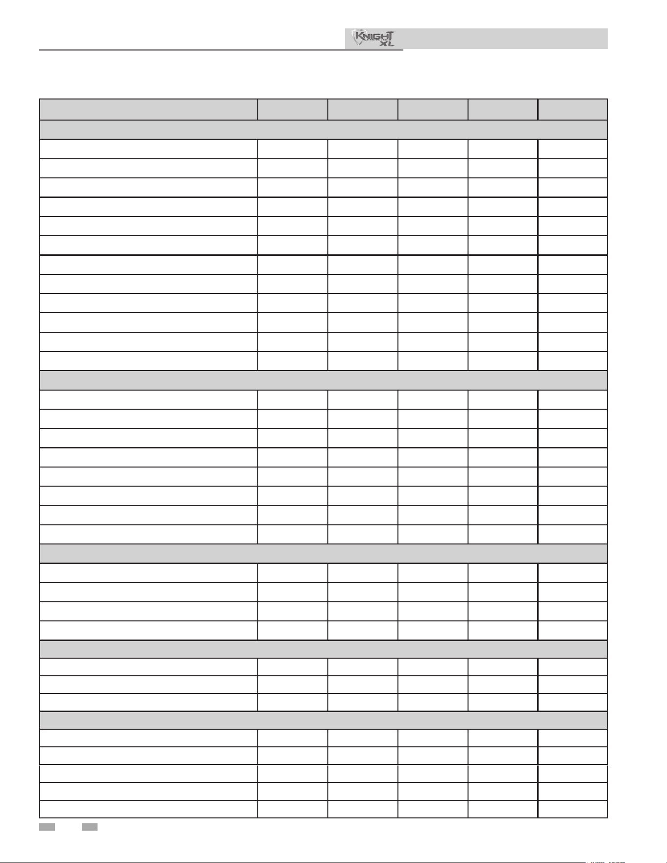
Product Summary
Installation & Operation Manual
KBX-0400 KBX-0500 KBX-0650 KBX-0800 KBX-1000
WATER
GALLON CAPACITY 4.4 4.9 6.2 7.3 8.8
HEATING SURFACE (SQ. FT.) 34.80 39.10 52.20 60.90 75.40
WATER CONNECTIONS 2" 2" 2" 2" 2-1/2"
20°F ΔT WATER FLOW (GPM) 38 48 62 76 96
HEAD LOSS (FT. OF HD.) 10.00 14.00 16.00 17.00 18.00
35°F ΔT WATER FLOW (GPM) 22 27 36 44 54
HEAD LOSS (FT. OF HD.) 4.00 8.00 7.00 9.00 6.00
MAX. WORKING PRESSURE (PSI) 160 160 160 160 160
# OF RELIEF VALVES 1 1 1 1 1
RELIEF VALVE SIZE 3/4" 3/4" 3/4" 3/4" 3/4"
RELIEF VALVE RATING (MBH) 697 697 697 1352 1352
RELIEF VALVE PRESSURE RATING (PSI) 50 50 50 50 50
GAS
INLET CONNECTION 1" 1" 1-1/4" 1-1/4" 1-1/4"
MAX. INLET PRESSURE, NAT 14.0" w.c. 14.0" w.c. 12.0" w.c. 12.0" w.c. 12.0" w.c.
MIN. INLET PRESSURE, NAT 4.0" w.c. 4.0" w.c. 4.0" w.c. 4.0" w.c. 4.0" w.c.
MAX. INLET PRESSURE, LP 14.0" w.c. 14.0" w.c. 14.0" w.c. 14.0" w.c. 14.0" w.c.
MIN. INLET PRESSURE, LP 8.0" w.c. 8.0" w.c. 8.0" w.c. 8.0" w.c. 8.0" w.c.
BTU/HR INPUT 399,000 500,000 650,000 800,000 999,000
BTU/HR OUTPUT (HIGH FIRE) 387,030 485,000 630,500 776,000 969,030
BTU/HR OUTPUT (LOW FIRE) 38,703 48,500 63,050 77,600 96,903
ELECTRICAL (Boiler and Pump Only)
VOLTAGE/HEATER 120 120 120 120 120
VOLTAGE/CONTROL 24 24 24 24 24
FLA 3.0 3.1 3.3 4.3 6.6
MCA 3.8 3.9 4.1 5.4 8.3
DIMENSIONS
HEIGHT 45" 45" 45" 45" 45"
WIDTH 24" 24" 24" 24" 24"
DEPTH 33-1/2" 33-1/2" 42-1/2" 42-1/2" 50"
SERVICE CLEARANCES
FRONT 24" 24" 24" 24" 24"
REAR 24" 24" 24" 24" 24"
RIGHT SIDE 0" 0" 0" 0" 0"
LEFT SIDE 0" 0" 0" 0" 0"
TOP 24" 24" 24" 24" 24"
9
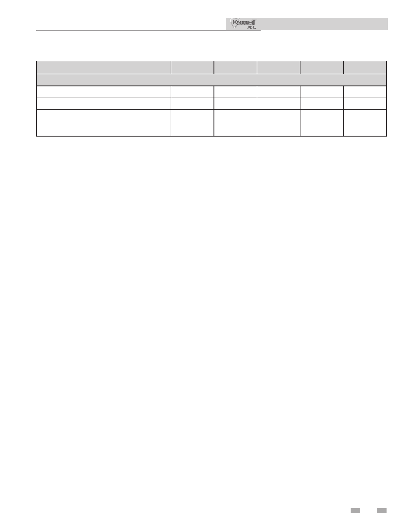
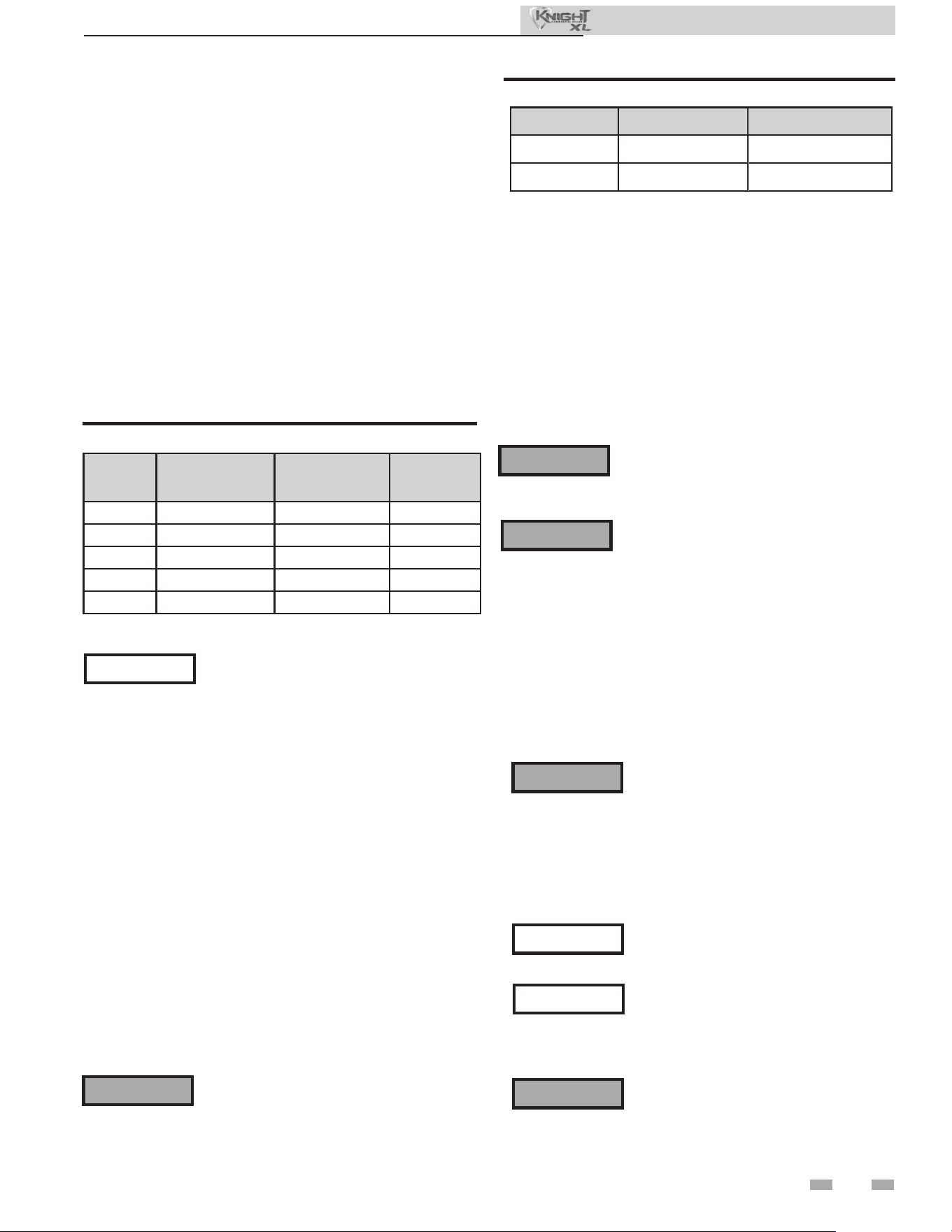
Product Summary continued (Indoor Models Only)
Installation & Operation Manual
KBX-0400 KBX-0500 KBX-0650 KBX-0800 KBX-1000
DIRECT VENTING
SIZE 4" 4" 6" 6" 6"
VENT CATEGORY IV IV IV IV IV
VENT MATERIAL
PVC/CPVC/
PP/ AL29-
4C
PVC/CPVC/
PP/ AL29-
4C
PVC/CPVC/
PP/ AL29-
4C
PVC/CPVC/
PP/ AL29-
4C
PVC/CPVC/
PP/ AL29-
4C
10
e Knight XL gas manifold and controls
met safe lighting and other performance
criteria when the boiler underwent tests
specied in ANSI Z21.13 – latest edition.
Failure to keep boiler area clear and free of
combustible materials, gasoline, and other
ammable liquids and vapors can result in
severe personal injury, death, or substantial
property damage.
Installation must comply with:
• Local, state, provincial, and national codes, laws,
regulations, and ordinances.
• National Fuel Gas Code, ANSI Z223.1 – latest edition.
• Standard for Controls and Safety Devices for Automatically
Fired Boilers, ANSI/ASME CSD-1, when required.
• National Electrical Code.
• For Canada only: B149.1 Installation Code, CSA C22.1
Canadian Electrical Code Part 1 and any local codes.
Before locating the boiler, check:
1. Check for nearby connection to:
• System water piping
• Venting connections
• Gas supply piping
• Electrical power
2. Locate the appliance so that if water connections should
leak, water damage will not occur. When such locations
cannot be avoided, it is recommended that a suitable
drain pan, adequately drained, be installed under the
appliance. e pan must not restrict combustion air
ow. Under no circumstances is the manufacturer to be
held responsible for water damage in connection with
this appliance, or any of its components.
3. Check area around the boiler. Remove any combustible
materials, gasoline and other ammable liquids.
4. e Knight XL must be installed so that gas control system
components are protected from dripping or spraying water
or rain during operation or service.
5. If a new boiler will replace an existing boiler, check for and
correct system problems, such as:
• System leaks causing oxygen corrosion or heat exchanger
cracks from hard water deposits.
• Incorrectly-sized expansion tank.
• Lack of freeze protection uids in boiler water causing
system and boiler to freeze and leak.
• Debris le from existing piping, if not ushed and cleaned
with an appropriate cleaner.
6. Check around the boiler for any potential air
contaminants that could risk corrosion to the boiler or
the boiler combustion air supply (see Table 1A). Prevent
combustion air contamination. Remove any of these
contaminants from the boiler area.
⚠ WARNING
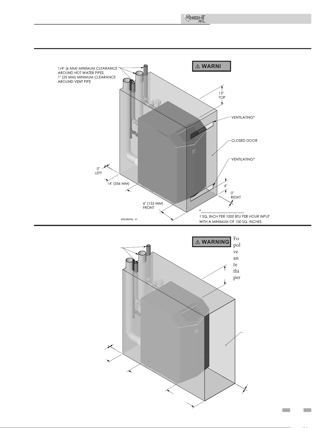
Provide clearances:
Clearances from combustible materials
1. Hot water pipes—at least 1/4" (6 mm) from combustible
materials.
2. Vent pipe – Follow special vent system manufacturer’s
instructions.
3. See FIG.’s 1-1 and 1-2 for other clearance minimums.
Recommended clearances for service access
- Front / Top / Rear................................................................ 24"
Closet and alcove installations
is appliance requires a special venting
system. e vent connection to the appliance
For closet and alcove installations as shown
in FIG.’s 1-1 and 1-2, CPVC or stainless steel
⚠ WARNING
⚠ WARNING
NOTICE
⚠ WARNING
1 Determine boiler location
A closet is any room the boiler is installed in which is less than
26 cubic feet for KBX400-500 models, 35 cubic feet for KBX650-
800 models, and 39 cubic feet for KBX1000 models.
An alcove is any room which meets the criteria for a closet with
the exception that it does not have a door.
Example: Room dimensions = 5 feet long, 4 feet wide, and 8
foot ceiling = 5 x 4 x 8 = 160 cubic feet. is would be considered
a closet for a Knight XL Boiler.
Installation & Operation Manual
Unless specied as an outdoor boiler, this
appliance is certied as an indoor appliance.
DO NOT install units in rooms or
environments that contain corrosive
contaminants (see Table 1A). Failure to
comply could result in severe personal injury,
death, or substantial property damage.
⚠ WARNING
If you do not provide the recommended
service clearances shown, it may not be
NOTICE
DO NOT install the boiler in a room likely to freeze.
Multiple appliances can be installed side by
side with no clearances between adjacent
NOTICE
vent material must be used inside the structure. e ventilating
air openings shown in FIG.’s 1-1 and 1-2 are required for this
arrangement. Failure to follow this warning could result in re,
personal injury, or death.
appliances because the appliances are approved for zero
clearances from combustible surfaces; however, service access
will be limited from the sides. Consult with the local inspection
authority for approval.
possible to service the boiler without removing it from the
space.
must be made with the starter CPVC/stainless steel pipe section.
e eld provided PVC vent ttings must be cemented to the
CPVC pipe section. Use only the vent materials, primer and
cement specied in this manual to make the vent connections.
Failure to follow this warning could result in re, personal
injury, or death.
Do not install the appliance outdoors or locate where the
appliance will be exposed to freezing temperatures
Do not install the appliance where condensation may form on
the inside or outside of the appliance, or where condensation
may fall onto the appliance.
Failure to install the appliance indoors could result in severe
personal injury, death, or substantial property damage.
11
1 Determine boiler location (continued)
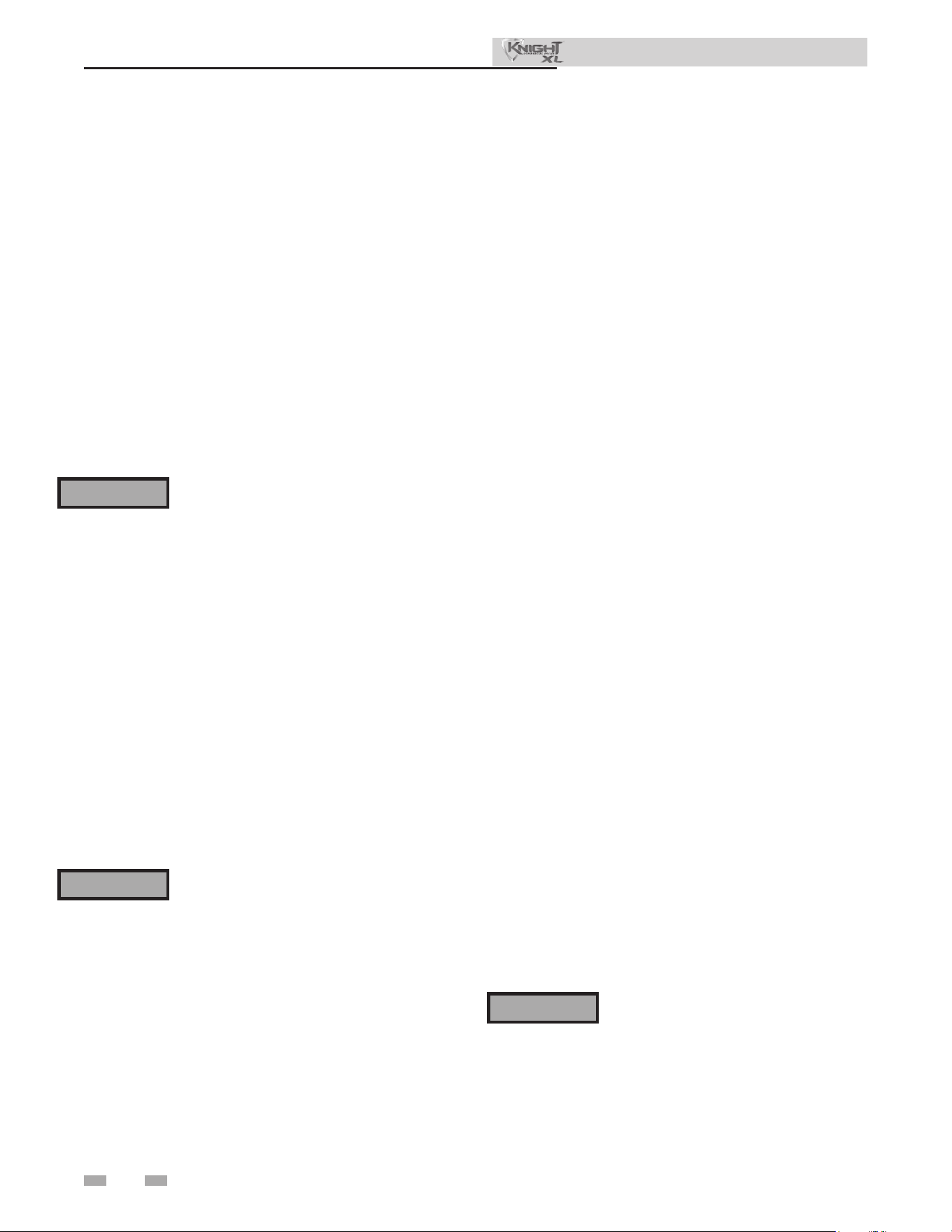
Figure 1-2 Alcove Installation - Minimum Required Clearances
Figure 1-1 Closet Installation - Minimum Required Clearances
⚠ WARNING
⚠ WARNING
Installation & Operation Manual
For alcove installations, CPVC,
polypropylene or stainless steel
vent material MUST BE used in
an alcove structure due to elevated
temperatures. Failure to follow
this warning could result in re,
personal injury, or death.
For closet installations, CPVC,
polypropylene or stainless steel
vent material MUST BE used in
a closet structure due to elevated
temperatures. Failure to follow
this warning could result in re,
personal injury, or death.
13"
TOP
14" (356 MM)
REAR
18" (457 MM)
FRONT
0"
LEFT
0"
RIGHT
1/4" (6 MM) MINIMUM CLEARANCE
AROUND HOT WATER PIPES
1" (25 MM) MINIMUM CLEARANCE
AROUND VENT PIPE
OPEN
FRONT
2000582944 01
REAR
AREA OF EACH OPENING
AIR OPENING
AIR OPENING
12
1 Determine boiler location
Provide air openings to room:
Knight XL alone in boiler room
1. No air ventilation openings into the boiler room are
needed when clearances around the Knight XL are
at least equal to the SERVICE clearances shown in
FIG.’s 1-1 and 1-2. For spaces that do NOT supply this
clearance, provide two openings as shown in FIG. 1-1.
Each opening must provide one square inch free area per
1,000 Btu/hr of boiler input.
Knight XL in same space with other gas or oil-red
appliances
1. Follow the National Fuel Gas Code (U.S.) or CSA B149.1
(Canada) to size/verify size of the combustion/ventilation
air openings into the space.
e space must be provided with
combustion/ventilation air openings
correctly sized for all other appliances
located in the same space as the Knight
XL.
Do not install the boiler in an attic.
Failure to comply with the above warnings
could result in severe personal injury,
death, or substantial property damage.
2. Size openings only on the basis of the other appliances in
the space. No additional air opening free area is needed
for the Knight XL because it takes its combustion air from
outside (direct vent installation).
Do not install the boiler on carpeting even
if foundation is used. Fire can result,
causing severe personal injury, death, or
substantial property damage.
If ooding is possible, elevate the boiler suciently to prevent
water from reaching the boiler.
Flooring and foundation
Flooring
e Knight XL is approved for installation on combustible
ooring, but must never be installed on carpeting.
Residential garage installation
Precautions
Take the following precautions when installing the appliance
in a residential garage. If the appliance is located in a
residential garage, it should be installed in compliance with
the latest edition of the National Fuel Gas Code, ANSI Z223.1
and/or CAN/CGA-B149 Installation Code.
• Appliances located in residential garages and in
adjacent spaces that open to the garage and are not part
of the living space of a dwelling shall be installed so that
all burners and burner ignition devices are located not
less than 18 inches (46 cm) above the oor.
• e appliance shall be located or protected so that it is
not subject to physical damage by a moving vehicle.
Vent and air piping
e Knight XL requires a special vent system, designed for
pressurized venting.
e boiler is to be used for either direct vent installation or
for installation using indoor combustion air. When room
air is considered, see the General Venting Section. Note
prevention of combustion air contamination below when
considering vent/air termination.
Vent and air must terminate near one another and may be
vented vertically through the roof or out a side wall, unless
otherwise specied. You may use any of the vent/air piping
methods covered in this manual. Do not attempt to install the
Knight XL using any other means.
Be sure to locate the boiler such that the vent and air piping
can be routed through the building and properly terminated.
e vent/air piping lengths, routing and termination method
must all comply with the methods and limits given in this
manual.
Prevent combustion air contamination
Install air inlet piping for the Knight XL as described in
this manual. Do not terminate vent/air in locations that
can allow contamination of combustion air. Refer to Table
1A for products and areas which may cause contaminated
combustion air.
You must pipe combustion air to the boiler
air intake. Ensure that the combustion air
will not contain any of the contaminants
in Table 1A. Contaminated combustion
air will damage the boiler, resulting in
possible severe personal injury, death
or substantial property damage. Do not
pipe combustion air near a swimming
pool, for example. Also, avoid areas
subject to exhaust fumes from laundry
facilities. ese areas will always contain
contaminants.
⚠ WARNING
⚠ WARNING
⚠ WARNING
Installation & Operation Manual
Seismic bracing
For installations requiring seismic bracing, the base legs of
the appliance are designed to allow for the use of unistrut
channel to meet seismic requirements.
13
Products to avoid:
Spray cans containing chloro/uorocarbons
Permanent wave solutions
Chlorinated waxes/cleaners
Chlorine-based swimming pool chemicals
Calcium chloride used for thawing
Sodium chloride used for water soening
Refrigerant leaks
Paint or varnish removers
Hydrochloric acid/muriatic acid
Cements and glues
Antistatic fabric soeners used in clothes dryers
Chlorine-type bleaches, detergents, and cleaning solvents
found in household laundry rooms
Adhesives used to fasten building products and other
similar products
Areas likely to have contaminants
Dry cleaning/laundry areas and establishments
Swimming pools
Metal fabrication plants
Beauty shops
Refrigeration repair shops
Photo processing plants
Auto body shops
Plastic manufacturing plants
Furniture renishing areas and establishments
New building construction
Remodeling areas
Garages with workshops
Table 1A Corrosive Contaminants and Sources
1 Determine boiler location (continued)
Installation & Operation Manual
Failure to follow all instructions can result
in ue gas spillage and carbon monoxide
emissions, causing severe personal injury
or death.
⚠ WARNING
When using an existing vent system to
install a new boiler:
Check the following venting components before installing:
• Material - For materials listed for use with this appliance,
see Section 3 - General Venting. For polypropylene or
stainless steel venting, an adapter of the same
manufacturer must be used at the ue collar connection.
• Size - To ensure proper pipe size is in place, see Table 3A.
Check to see that this size is used throughout the vent
system.
• Manufacturer - For a stainless steel or polypropylene
application, you must use only the listed manufacturers
and their type product listed in Tables 3H and 3I for CAT
IV positive pressure venting with ue producing
condensate.
• Supports - Non-combustible supports must be in place
allowing a minimum 1/4" rise per foot. e supports
should adequately prevent sagging and vertical slippage,
by distributing the vent system weight. For additional
information, consult the vent manufacturer’s
instructions for installation.
• Terminations - Carefully review Sections 3 through 5 to
ensure requirements for the location of the vent and air
terminations are met and orientation of these t the
appropriate image from the Sidewall or Vertical
options listed in the General Venting Section. For
stainless steel vent, only use terminations listed in Table
3J for the manufacturer of the installed vent.
• Seal - With prior requirements met, the system should be
tested to the procedure listed in parts (c) through (f) of
the Removal of an Existing Boiler Section of this manual.
With polypropylene and stainless steel vent, seal and connect
all pipe and components as specied by the vent manufacturer
used; with PVC/CPVC vent, see the Installing Vent or Air
Piping Section of this manual.
⚠ WARNING
If any of these conditions are not met,
the existing system must be updated
or replaced for that concern. Failure to
follow all instructions can result in ue gas
spillage and carbon monoxide emissions,
causing severe personal injury or death.

1 Determine boiler location
14
When removing a boiler from existing
common vent system:
Do not install the Knight XL into a
common vent with any other appliance.
is will cause ue gas spillage or appliance
malfunction, resulting in possible severe
personal injury, death, or substantial
property damage.
At the time of removal of an existing boiler, the following steps
shall be followed with each appliance remaining connected
to the common venting system placed in operation, while
the other appliances remaining connected to the common
venting system are not in operation.
a. Seal any unused openings in the common venting system.
b. Visually inspect the venting system for proper size and
horizontal pitch and determine there is no blockage
or restriction, leakage, corrosion, or other deciencies,
which could cause an unsafe condition.
c. Test vent system – Insofar as is practical, close all building
doors and windows and all doors between the space
in which the appliances remaining connected to the
common venting system are located and other spaces of
the building. Turn on clothes dryers and any appliance
not connected to the common venting system. Turn on
any exhaust fans, such as range hoods and bathroom
exhausts, so they will operate at maximum speed. Do not
operate a summer exhaust fan. Close replace dampers.
d. Place in operation the appliance being inspected. Follow
the lighting instructions. Adjust thermostat so appliance
will operate continuously.
e. Test for spillage at the dra hood relief opening aer
5 minutes of main burner operation. Use the ame of a
match or candle, or smoke from a cigarette, cigar, or pipe.
f. Aer it has been determined that each appliance
remaining connected to the common venting system
properly vents when tested as outlined herein, return
doors, windows, exhaust fans, replace dampers, and any
other gas-burning appliance to their previous conditions
of use.
⚠ DANGER
g. Any improper operation of the common venting system
should be corrected so the installation conforms with the
National Fuel Gas Code, ANSI Z223.1/NFPA 54 and/or
CAN/CSA B149.1, Natural Gas and Propane Installation
Code. When resizing any portion of the common venting
system, the common venting system should be resized
to approach the minimum size as determined using the
appropriate tables in Part 11 of the National Fuel Gas Code,
ANSI Z223.1/NFPA and/or CAN/CSA B149.1, Natural Gas
and Propane Installation Code.
Installation & Operation Manual
2 Prepare boiler
15
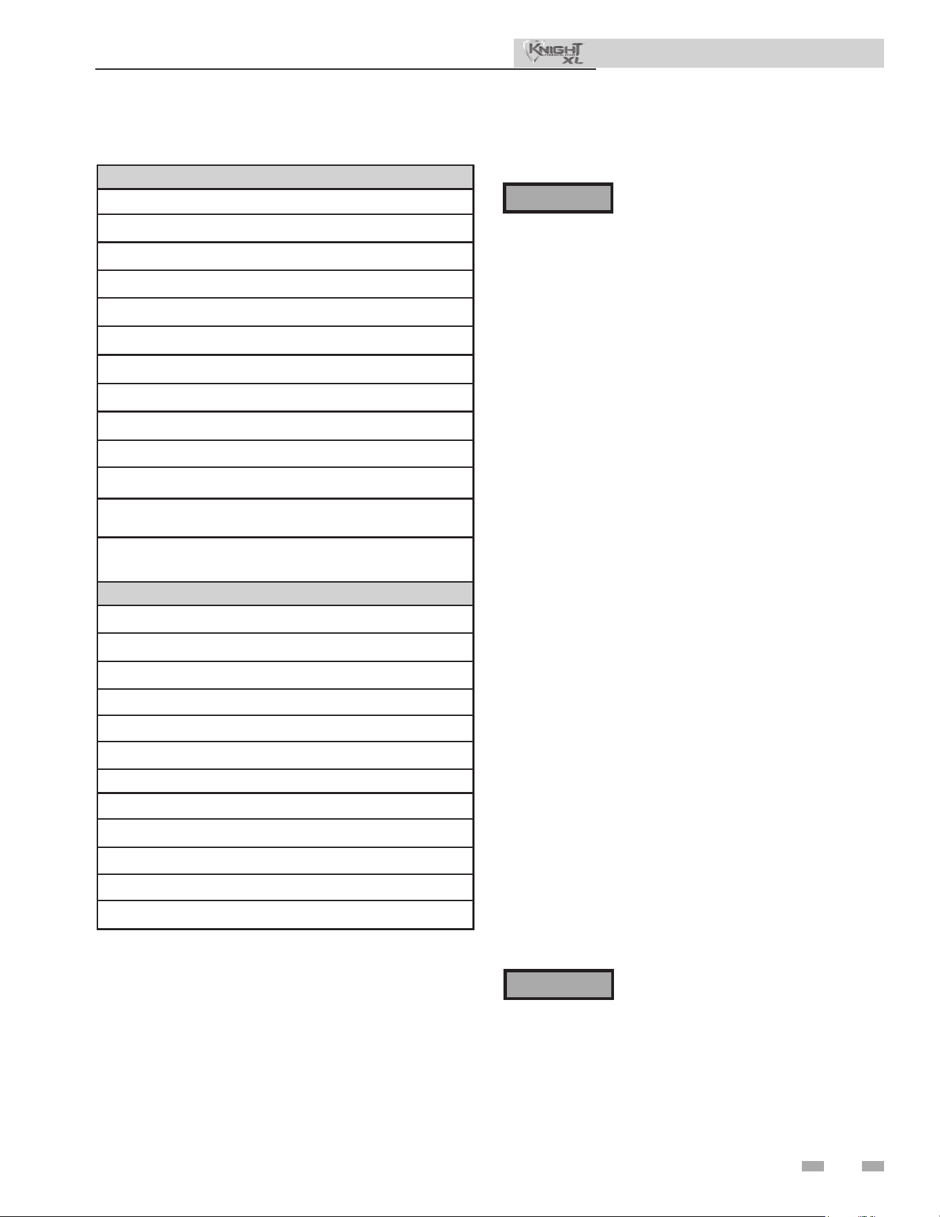
Remove boiler from wood pallet
1. Aer removing the outer shipping carton from the boiler,
remove the parts box.
2. To remove the boiler from the pallet remove the four (4)
lag bolts located at the front and rear of the boiler (FIG.
2-1).
Do not drop the boiler or bump the jacket
on the oor or pallet. Damage to the boiler
can result.
For a boiler already installed, you must
turn o gas supply, turn o power and
allow boiler to cool before proceeding.
You must also completely test the boiler
aer conversion to verify performance
as described under Start-up, Section 10
of this manual. Failure to comply could
result in severe personal injury, death, or
substantial property damage.
RIGHT
LAG BOLTS
(QTY. 2)
LEFT
LAG BOLTS
(QTY. 2)
DIR #2000585120 00
Figure 2-1 Boiler Mounted on Shipping Pallet
Gas conversions
NOTICE
⚠ WARNING
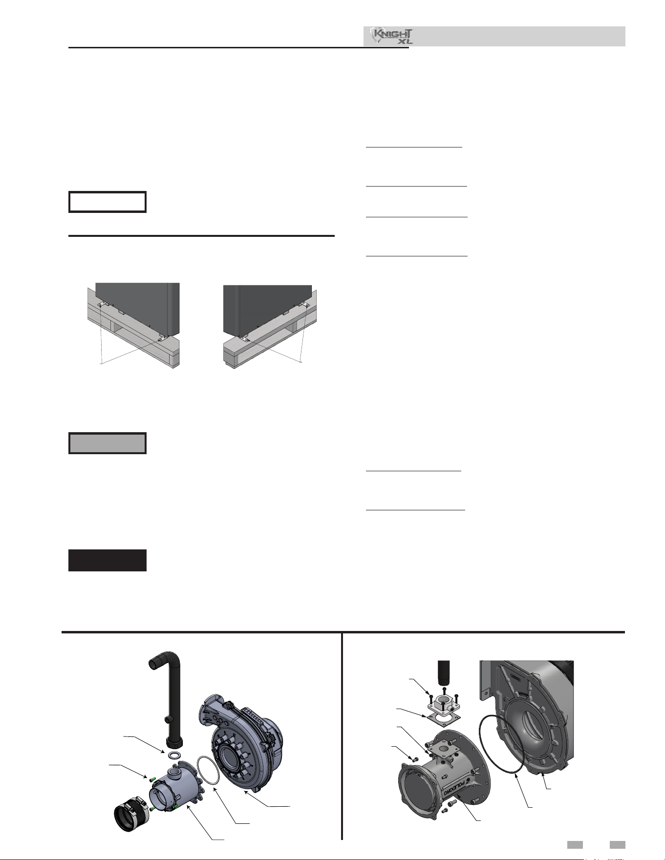
Figure 2-2A Installing Propane Orice - Models 400-500
Models 400-1000 (Venturi)
1. Remove the front access panel from the unit (no tools
required for removal).
2. For Models 400-500: Disconnect the air inlet piping from
the venturi by loosening the band clamp around the rubber
boot coupling. Slide the rubber boot o of the venturi.
For Models 650-1000: Disconnect the venturi from the air
box by removing the four (4) bolts securing it to the air box.
3. For Models 400-500: Disconnect the gas piping from
the venturi by loosening the threaded nut on the venturi.
Replace gasket if damaged.
For Models 650-1000: Disconnect the gas piping from the
venturi by removing the four (4) bolts securing the pipe to
the venturi.
4. Remove the bolts connecting the venturi to the fan. Remove
the natural venturi from the unit (FIG.’s 2-2A and 2-2B).
5. Install the LP venturi onto the fan taking note of the
following:
a. e UP arrow on the plastic housing is indeed pointing
up.
b. e connection for the gas piping is facing towards the
top of the unit. Reinstall the bolts connecting the
venturi to the fan.
6. Reassemble the gas pipe to the venturi. Install the new
gasket provided in the kit and ensure it is seated properly
before tightening.
7. For Models 400-500: Reconnect the rubber boot on the air
inlet to the venturi inlet and tighten the band clamp at this
connection.
For Models 650-1000: Reinstall the four (4)bolts connecting
the venturi to the air box and tighten.
8. Aer installation is complete, attach the propane conversion
label (in the conversion kit) next to the boiler rating plate.
Attach the LP caution label (in the conversion kit) to the rear
of the boiler underneath the gas supply piping.
⚠ DANGER
Inspect the O-ring when the blower is
disassembled. e O-ring must be in good
condition and must be installed. Failure to
comply will cause a gas leak, resulting in
severe personal injury or death.
Installation & Operation Manual
DIR #2000582948 00
BLOWER
O-RING
SCREWS
QTY. 4
VENTURI
SCREWS
QTY. 7
GASKET
NUTS
QTY. 4
Figure 2-2B Installing Propane Orice - Models 650-1000
2000618215 00
VENTURI
O-RING
BLOWER
SCREWS
QTY. 3
O-RING
2 Prepare boiler
16
DIR #2000582949 00
DIR #20005829490
0
DIR
#
2
0
0
0
5
8
2
9
4
9
0
0
DIR #20005829490
0
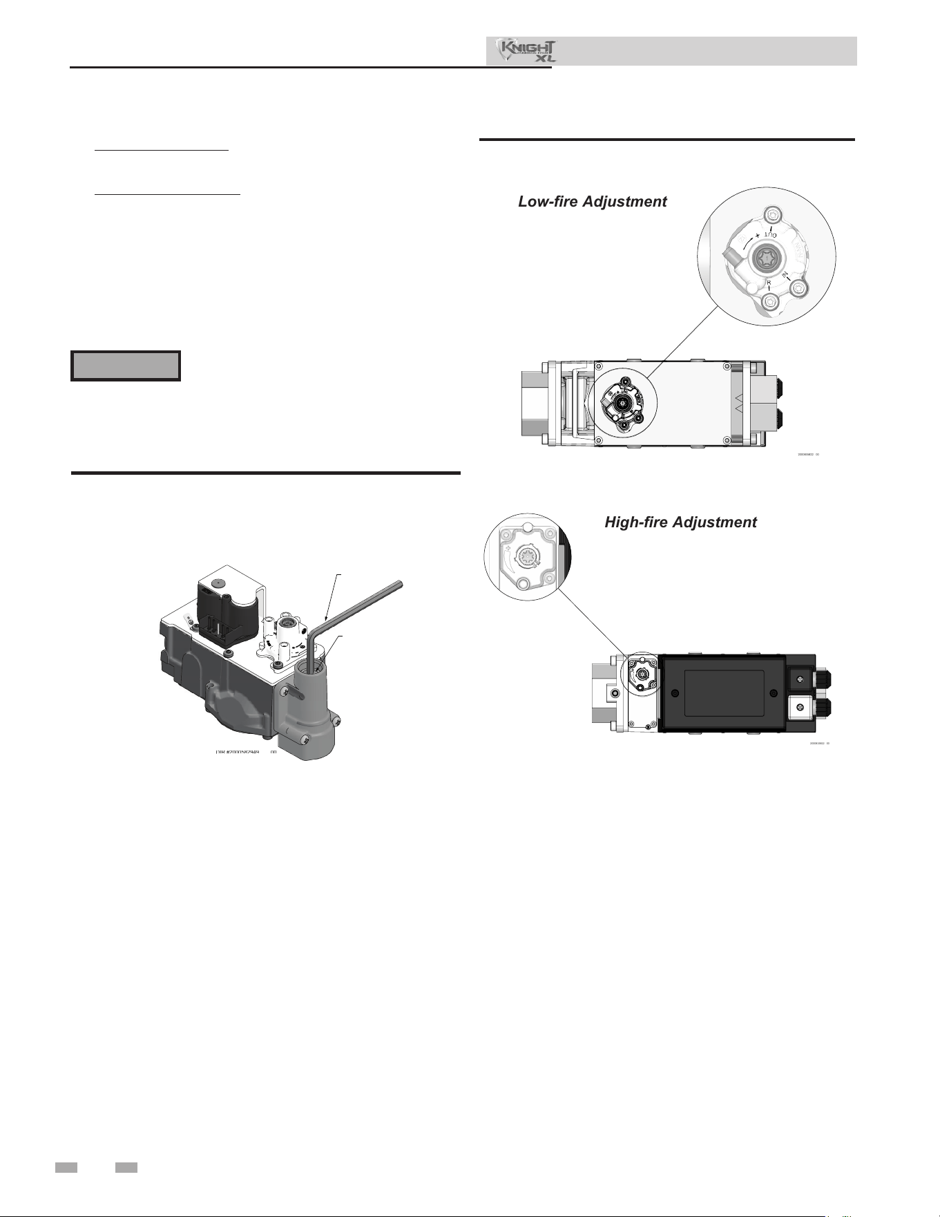
ALLEN
WRENCH
ADJUSTMENT
SCREW
Figure 2-3 Gas Valve Adjustment - Models 400-500
Series 100 - 101
Low-re Adjustment
High-re Adjustment
10. For Models 400-500: Remove the front panel from the unit
(no tools required for removal).
For Models 650-1000: Remove the top access cover from
the unit (no tools required for removal).
11. Use a combustion analyzer to verify CO
2
is within the
range of 9.4 – 10.4%. If not, adjust the screw clockwise
incrementally to raise CO
2
and counterclockwise to lower
CO
2
(FIG. 2-3 and 2-4).
12. Replace the front access panel removed in Step 1 and resume
operation.
Figure 2-4 Gas Valve Adjustment - Models 650 - 1000
Series 110 - 111
⚠ WARNING
Aer converting to LP, check combustion
per the Start-up procedure in Section 11
of this manual. Failure to check and verify
combustion could result in severe personal
injury, death, or substantial property damage.
Installation & Operation Manual
Combustion air lter
is unit has a standard air lter located at the combustion air
inlet. is air lter is provided to help ensure clean air is used
for the combustion process. Check this lter every month and
replace when it becomes dirty. You can nd these commercially
available lters at any home center or HVAC supply store.
Filters by model sizes:
KBX0400-1000 / 12 x 12 x 1 lter
Note: Replacement lter should have a MERV rating no greater
than 4.
Follow the steps below when replacing the combustion air lter:
1. Locate the combustion air lter box.
2. Li and remove the air lter box cover to gain access to the
air lter.
3. Slide the air lter out the top of the air lter box.
4. Inspect the air lter for dirt and debris, replace if necessary.
5. Replace the air lter and the air lter box cover.
2000835822 00
2000835822 00
17
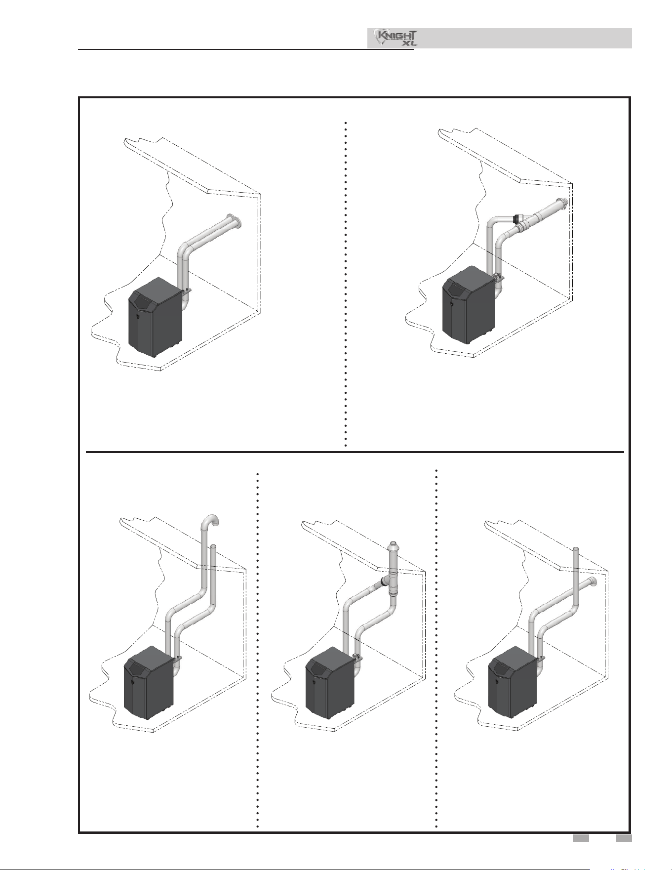
Two Pipe Sidewall
DIR #2000583013 00
PVC/CPVC Concentric Sidewall
Models 400 - 500 Only
Direct venting options - Sidewall Vent
DIR #2000583014 00
3 General venting
Installation & Operation Manual
DIR #2000583015 00
Two Pipe Vertical
DIR #2000583017 00
Vertical Vent, Sidewall Air
PVC/CPVC
Concentric Vertical
Models 400 - 500 Only
DIR #2000583016 00
Direct venting options - Vertical Vent
18
3 General venting
Installation & Operation Manual
is appliance requires a special venting
system. Use only approved stainless steel,
PVC, CPVC or polypropylene pipe and
ttings listed in Tables 3H, 3I, and 3J for
vent pipe, and ttings. Failure to comply
could result in severe personal injury,
death, or substantial property damage.
Installation must comply with local
requirements and with the National
Fuel Gas Code, ANSI Z223.1 for U.S.
installations or CSA B149.1 for Canadian
installations.
Install vent and combustion air piping
⚠ DANGER
e Knight XL boiler must be vented and
supplied with combustion and ventilation
air as described in this section. Ensure the
vent and air piping and the combustion
air supply comply with these instructions
regarding vent system, air system, and
combustion air quality. See also Section 1
of this manual.
Inspect nished vent and air piping
thoroughly to ensure all are airtight and
comply with the instructions provided and
with all requirements of applicable codes.
Failure to provide a properly installed vent
and air system will cause severe personal
injury or death.
⚠ WARNING
NOTICE
⚠ WARNING
For closet and alcove installations, CPVC,
polypropylene or stainless steel material
MUST BE used in a closet/alcove structure.
Failure to follow this warning could result
in re, personal injury, or death.
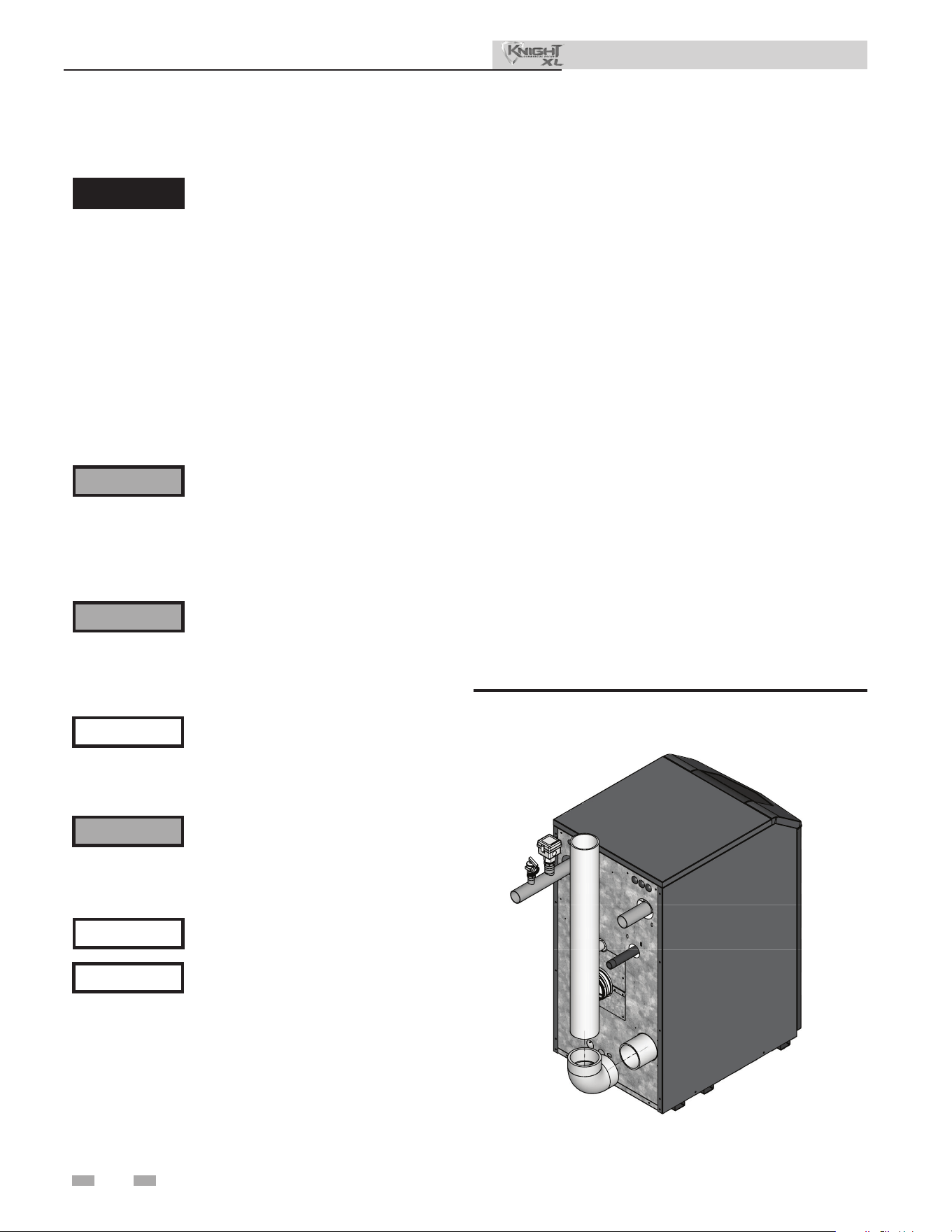
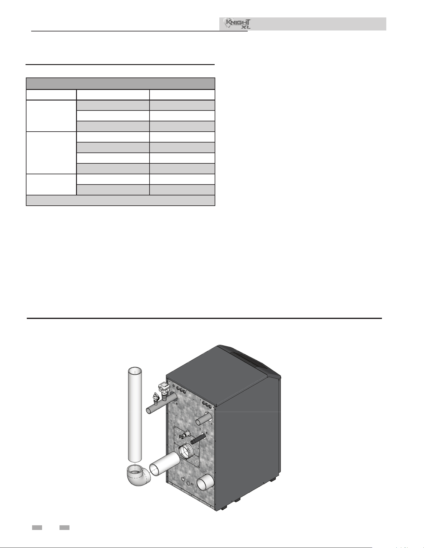
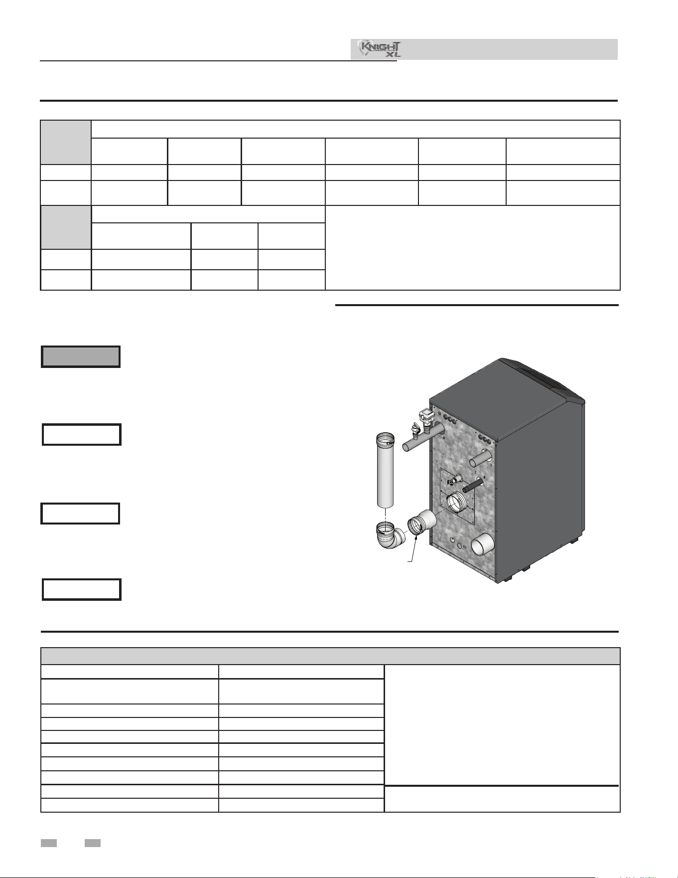
Air intake/vent connections
1. Combustion Air Intake Connector (FIG. 3-1) - Used to
provide combustion air directly to the unit from outdoors. A
tting is provided on the unit for nal connection.
Combustion air piping must be supported per guidelines
listed in the National Mechanical Code, Section 305, Table
305.4 or as local codes dictate.
2. Vent Connector (FIG.'s 3-2 thru 3-5) - Used to provide a
passageway for conveying combustion gases to the
outside. A transition tting is provided on the unit for
nal connection. Vent piping must be supported per the
National Building Code, Section 305, Table 305.4 or as
local codes dictate.
e Knight XL boiler vent and air piping can be installed
through the roof or through a sidewall. Follow the procedures
in this manual for the method chosen. Refer to the information
in this manual to determine acceptable vent and air piping
length.
You may use any of the vent/air piping methods covered in this
manual. Do not attempt to install the Knight XL boiler using
any other means.
You must also install air piping from outside to the boiler
air intake adapter unless following the Optional Room Air
instructions in this manual. e resultant installation is direct
vent (sealed combustion).
⚠ WARNING
DO NOT mix components from dierent
systems. e vent system could fail,
causing leakage of ue products into the
living space. Mixing of venting materials
will void the warranty and certication of
the appliance.
Improper installation of venting systems
may result in injury or death.
⚠ CAUTION
Follow the instructions in Section 1 of this
manual when removing a boiler from an
existing vent system.
NOTICE
DIR #2000585133 00
Figure 3-1 Near Boiler Air Piping
3 General venting (continued)
Installation & Operation Manual
Requirements for installation in
Canada
1. Installations must be made with a vent pipe system
certied to ULC-S636.
2. e rst three (3) feet of plastic vent pipe from the
appliance ue outlet must be readily accessible for visual
inspection.
3. e components of the certied vent system must not be
interchanged with other vent systems or unlisted
pipe/ttings. For concentric vent installations, the inner
vent tube must be replaced with eld supplied certied vent
material to comply with this requirement.
4. e 4" Concentric Vent Kit available from Lochinvar (see
Section 4 – Sidewall Termination – Optional Concentric
Vent) and the 4" Concentric Vent Kit available from IPEX
are both approved for use on the Knight XL (400 - 500
models only) boiler. Both kits are listed to the ULC-S636
standard for use in Canada.
Sizing
Increasing or decreasing combustion air
or vent piping sizes is not authorized.
NOTICE
Model Air Intake Vent
400 - 500 4 inches (102 mm) 4 inches (102 mm)
650 - 800 4 inches (102 mm) 6 inches (152 mm)
1000 6 inches (152 mm) 6 inches (152 mm)
e Knight XL uses model specic combustion air intake and
vent piping sizes as detailed in Table 3A below.
Table 3A Air Intake/Vent Piping Sizes
Model Kit Number
Equivalent
Vent Length
400 100140484 30 Feet (9 m)
500 100140484 30 Feet (9 m)
Table 3B Concentric Vent Kit Equivalent Vent Lengths
Minimum / Maximum allowable
combustion air and vent piping lengths
are as follows:
Combustion Air = 12 equivalent feet (3.7 m) minimum / 150
equivalent feet (30.5 m) maximum
Vent = 12 equivalent feet (3.7 m) minimum / 150 equivalent
feet (30.5 m) maximum
When determining equivalent combustion air and vent
length, add 5 feet (1.5m) for each 90° elbow and 3 feet (.9 m)
for each 45° elbow.
EXAMPLE: 20 feet (6 m) of PVC pipe + (3) 90° elbows +
(3) 45° elbows + (1) concentric vent kit (100140484) = 49
equivalent feet (15 m) of piping.
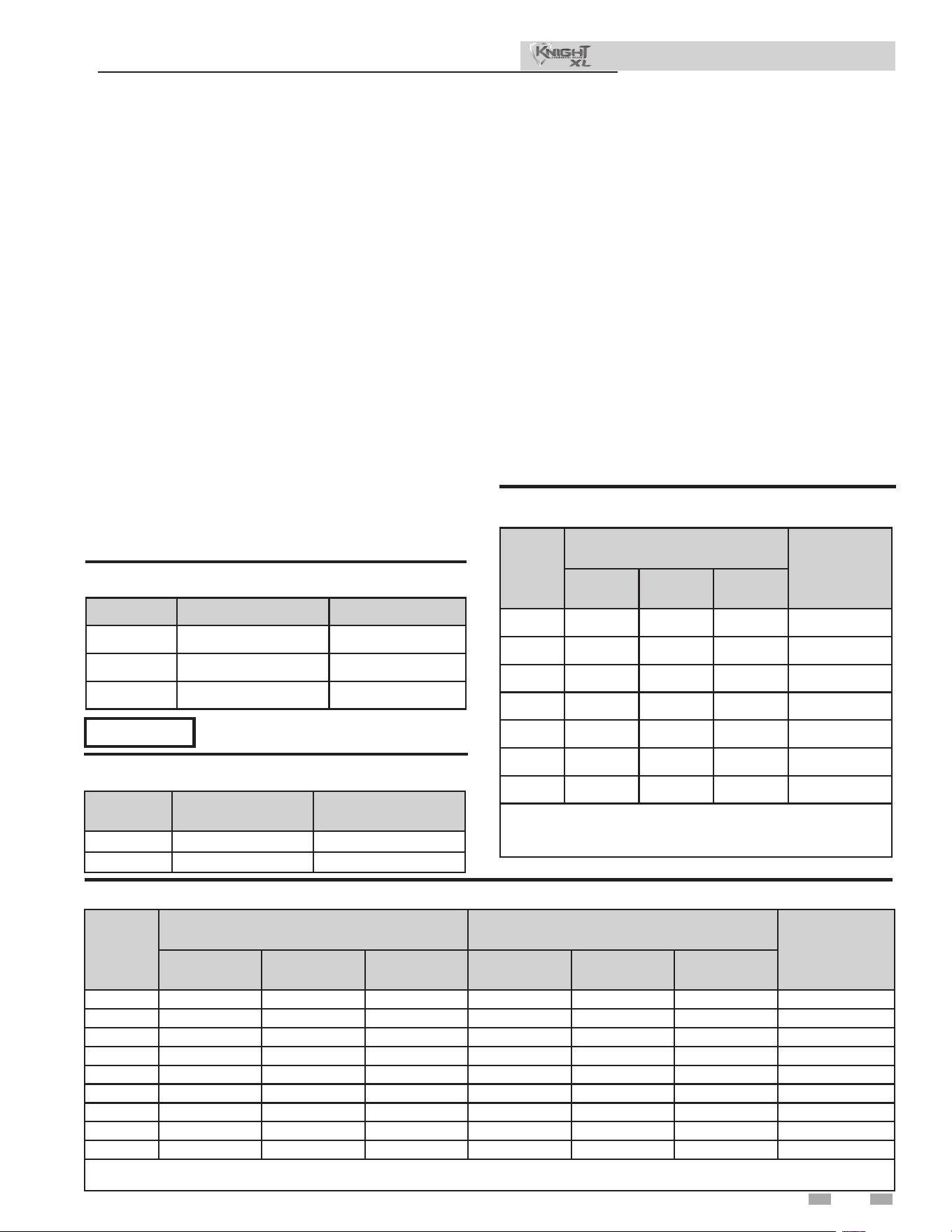
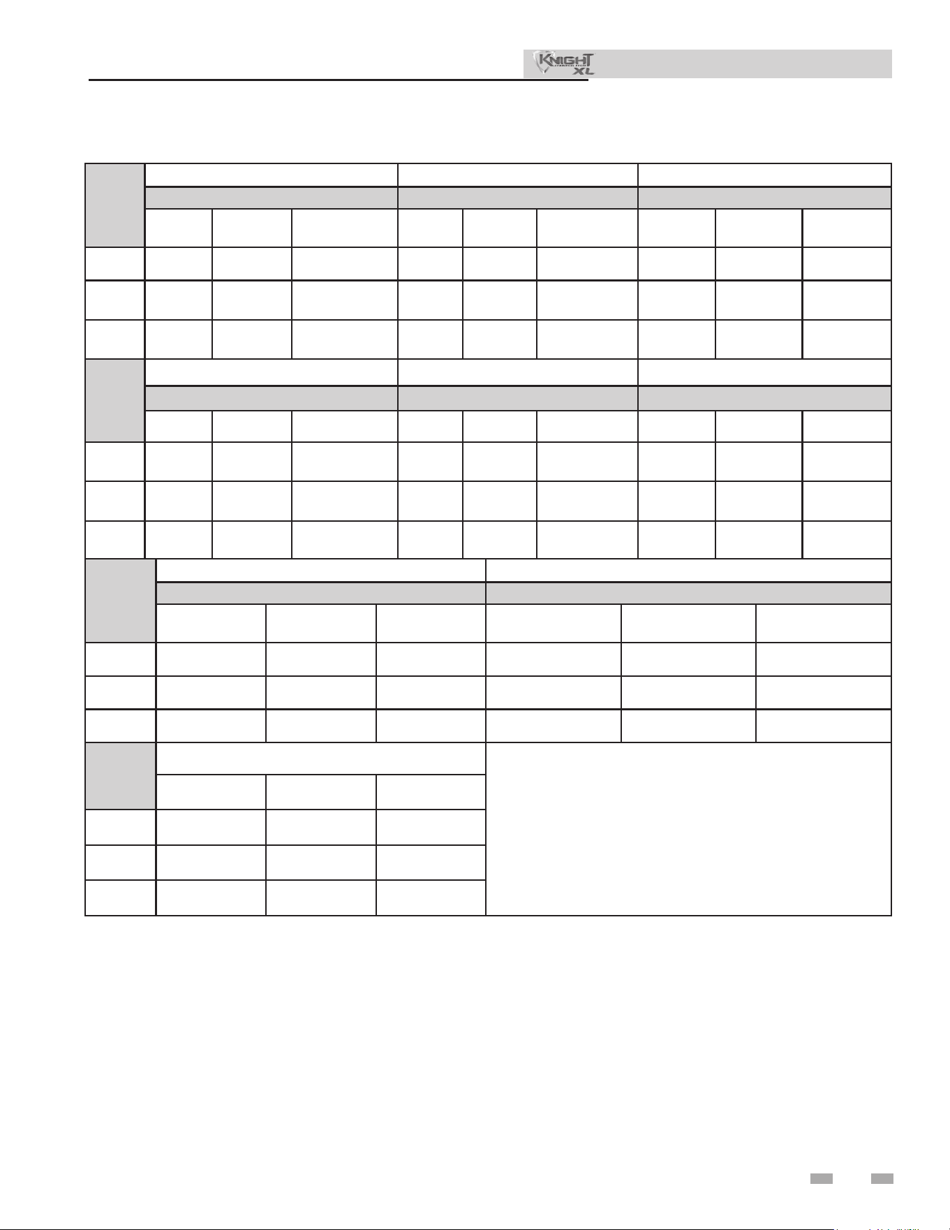
Model
Air Inlet Vent
Input De-Rate
per 25 Feet of
Vent
Air Intake
Diameter
Air Intake Min.
Length
Air Intake Max.
Length
Vent Diameter
Vent Min.
Length
Vent Max.
Length
400 4" 12' 150' 4" 12' 150' 0.78%
500 4" 12' 150' 4" 12' 150' 0.83%
650N* 4" 12' 80' 4" 12' 80' 0.29%
650L* 4" 12' 30' 4" 12' 30' 0.81%
650 4" 12' 150' 6" 12' 150' 2.00%
650 6" 12' 150' 6" 12' 150' 0.60%
800 4" 12' 100' 6" 12' 100' 0.63%
800 6" 12' 150' 6" 12' 150' 0.38%
1000 6" 12' 150' 6" 12' 150' 1.00%
*When using 4” vent for the 650 model, the allowable vent length for propane models is dierent from the allowable vent length for natural
gas models.
Model
Vent
Input De-Rate
per 25 Feet
of Vent
Vent
Diameter
Vent Min.
Length
Vent Max.
Length
400 4" 12' 150' 0.56%
500 4" 12' 150' 0.50%
650N* 4" 12' 80' 0.30%
650L* 4" 12' 30' 0.82%
650 6" 12' 150' 0.10%
800 6" 12' 150' 0.50%
1000 6" 12' 150' 0.66%
*When using 4” vent for the 650 model, the allowable vent length for
propane models is dierent from the allowable vent length for natural
gas models.
Table 3D Direct Vent Minimum/Maximum Allowable Air/Vent Lengths
Table 3C Room Air Minimum/Maximum Allowable Vent
Lengths
19
20
3 General venting
Air inlet pipe materials:
e air inlet pipe(s) must be sealed. Choose acceptable
combustion air inlet pipe materials from the following list:
PVC, CPVC, Polypropylene or ABS
Dryer Vent or Sealed Flexible Duct (not recommended for
rooop air inlet)
Galvanized steel vent pipe with joints and seams sealed as
specied in this section.
Type “B” double-wall vent with joints and seams sealed as
specied in this section.
AL29-4C, stainless steel material to be sealed to
specication of its manufacturer.
*Plastic pipe may require an adapter (not provided) to transition
between the air inlet connection on the appliance and the plastic
air inlet pipe.
Installation & Operation Manual
⚠ WARNING
Using air intake materials other than those
specied can result in personal injury, death
or property damage.
NOTICE
e use of double-wall vent or insulated
material for the combustion air inlet pipe is
Sealing of Type “B” double-wall vent material or galvanized
vent pipe material used for air inlet piping on a sidewall or
vertical rooop Combustion Air Supply System:
a. Seal all joints and seams of the air inlet pipe using either
Aluminum Foil Duct Tape meeting UL Standard 723 or
181A-P or a high quality UL Listed silicone sealant such as
those manufactured by Dow Corning or General Electric.
b. Do not install seams of vent pipe on the bottom of
horizontal runs.
c. Secure all joints with a minimum of three (3) sheet metal
screws or pop rivets. Apply Aluminum Foil Duct Tape or
silicone sealant to all screws or rivets installed in the vent
pipe.
d. Ensure that the air inlet pipes are properly supported.
⚠ DANGER
Failure to properly seal all joints and seams
as required in the air inlet piping may result
in ue gas recirculation, spillage of ue
products and carbon monoxide emissions
causing severe personal injury or death.
e PVC, CPVC, or ABS air inlet pipe should be cleaned and
sealed with the pipe manufacturer’s recommended solvents
and standard commercial pipe cement for the material used.
e PVC, CPVC, ABS, Dryer Vent or Flex Duct air inlet pipe
should use a silicone sealant to ensure a proper seal at the
appliance connection and the air inlet cap connection. Dryer
vent or ex duct should use a screw type clamp to seal the vent
to the appliance air inlet and the air inlet cap. Proper sealing
of the air inlet pipe ensures that combustion air will be free of
contaminants and supplied in proper volume.
Follow the polypropylene manufacturer’s instructions when
using polypropylene material as an inlet pipe.
When a sidewall or vertical rooop combustion air supply
system is disconnected for any reason, the air inlet pipe
must be resealed to ensure that combustion air will be free of
contaminants and supplied in proper volume.
Common venting
Knight XL boilers may be common vented; however, the
following criteria MUST BE followed:
1. Only Knight XL boilers may be connected to the common
vent. DO NOT mix other manufacturer’s appliances or
other Lochinvar models.
2. Knight XL boilers connected to the common vent must all be
of the same size.
3. Each Knight XL boiler must have a Lochinvar supplied ue
damper installed (see Table 3E).
4. A condensate drain must be installed above the ue damper.
5. Only vertical direct vent, positive pressure, Category IV or
vertical/chimney vent, negative pressure, Category II may
be used when common venting Knight XL boilers. Sidewall
common venting is not allowed.
6. Knight XL boilers in a common vent must be connected
and controlled with the integral Knight XL SMART TOUCH
Cascade.
a. e leader may be controlled through the Knight XL
SMART TOUCH control through BMS (external
0-10V signal), ModBus, BACnet, or its own internally
calculated set point.
b. e Cascade (Members) must be controlled by the
Knight XL Leader water heater using the Lead/Lag
Cascade option.
For approved common vent sizing, contact the factory.
Knight XL boilers cannot be connected using a common air
system.
⚠ WARNING
When Knight XL boilers are common vented,
the criteria above MUST BE followed. Failure
to follow all these requirements will result in
severe personal injury, death, or substantial
property damage.
NOTICE
A eld supplied inline condensate collection
section MUST BE installed directly above the
backow preventer.
⚠ WARNING
When Knight XL boilers are common vented,
hot water generators must be piped to the
primary heating loop and tank thermostats
must not be connected to the Knight XL.
Flue Damper Kits
Model Damper Size Kit Number
400 4" 100056141
500 4" 100056141
650 6" 100056142
800 6" 100056142
1000 6" 100056142
Table 3E Flue damper kits
recommended in cold climates to prevent the condensation of
airborne moisture in the incoming combustion air.
21
3 General venting (continued)
Installation & Operation Manual
Air contamination
Pool and laundry products and common household and hobby
products oen contain uorine or chlorine compounds. When
these chemicals pass through the boiler, they can form strong
acids. e acid can eat through the boiler wall, causing serious
damage and presenting a possible threat of ue gas spillage or
boiler water leakage into the building.
Please read the information given in Table 1A listing
contaminants and areas likely to contain them. If contaminating
chemicals will be present near the location of the boiler
combustion air inlet, have your installer pipe the boiler
combustion air and vent to another location, per this manual.
If the boiler combustion air inlet is located in
a laundry room or pool facility, for example,
these areas will always contain hazardous
contaminants.
To prevent the potential of severe personal
injury or death, check for areas and products
listed in Table 1A before installing the boiler
or air inlet piping.
If contaminants are found, you MUST:
• Remove contaminants permanently.
—OR—
• Relocate air inlet and vent terminations
to other areas.
⚠ WARNING
⚠ WARNING
Optional room air
⚠ WARNING
When utilizing the single pipe method,
provisions for combustion and ventilation
Table 3G Optional Room Air Kit
Commercial applications utilizing the Knight XL boiler may
be installed with a single pipe carrying the ue products to
the outside while using combustion air from the equipment
room. In order to use the room air venting option the following
conditions and considerations must be followed.
• e unit MUST be installed with the appropriate room
air kit (Table 3G).
• e equipment room MUST be provided with properly
sized openings to assure adequate combustion air.
Please refer to instructions provided with the room air
kit.
• ere will be a noticeable increase in the noise level
during normal operation from the inlet air opening.
• Using the room air kit makes the unit vulnerable to
combustion air contamination from within the
building. Please review Section 1, Prevent Combustion
Air Contamination, to ensure proper installation.
• Vent system and terminations must comply with the
standard venting instructions set forth in this manual.
NOTICE
Optional room air is intended for commercial
applications. Combustion air piping to the
Model Kit Number Description
400 - 800
100157616 Room Air Kit
1000
100344020 Room Air Kit
Installing vent and air piping
Use only cleaners, primers, and solvents
that are approved for the materials which
are joined together.
NOTICE
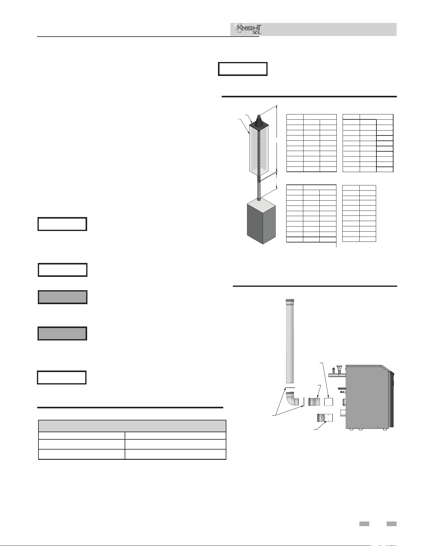
PVC/CPVC
All PVC vent pipes must be glued, properly
supported, and the exhaust must be
pitched a minimum of a 1/4 inch per foot
back to the boiler (to allow drainage of
condensate).
NOTICE
⚠ WARNING
e vent connection to the appliance must
be made with the CPVC pipe section if
⚠ WARNING
Insulation should not be used on PVC
or CPVC venting materials. e use of
insulation will cause increased vent wall
temperatures, which could result in vent
pipe failure.
is product has been approved for use with the PVC/CPVC
vent materials listed in Table 3H.
Model
Category IV
Standard Vent
Size
Category II
Increaser Size
Maximum
Vent Length
400 4" 6" 150'
500 4" 6" 150'
650 6" 8" 150'
800 6" 8" 150'
1000 6" 8" 150'
Table 3F Category IV to Category II Conversion Chart
Common venting CAT II:
Flues of multiple appliances may be combined by incorporating
a vent increaser to change the Category IV appliance to a
Category II vent system which can be common vented using
an engineered vent system. An increaser must be used and
the combined engineered vent system must be designed to
ensure that ue products will be properly exhausted from the
building at all times. Failure to use the correct vent increaser
or a properly sized vent system may result in a hazardous
condition where ue gases spill into an occupied living
space. Consult a vent designer to determine the diameter of
the common vent pipe required for combined vent installation.
It is recommended that all vent joints and seams are sealed
gastight. is vent system has specic vent material and
installation requirements. e negative dra in a conventional
vent installation must be within the range of 0.02 to 0.08 inches
w.c. to ensure proper operation. Make all dra readings while
the unit is in stable operation (approximately 2 to 5 minutes).
air must be in accordance with Air for Combustion and
Ventilation, of the latest edition of the National Fuel Gas
Code, ANSI Z223.1, in Canada, the latest edition of CGA
Standard B149 Installation Code for Gas Burning Appliances
and Equipment, or applicable provisions of the local building
codes.
outside is recommended for residential applications.
PVC/CPVC vent is to be used. e eld provided vent ttings
must be cemented to the CPVC pipe section using an “All
Purpose Cement” suitable for PVC and CPVC pipe. Use only
the vent materials, primer, and cement specied in Table 3H
to make the vent connections. Failure to follow this warning
could result in re, personal injury, or death.
22
3 General venting
Installation & Operation Manual
5. Dry t vent or air piping to ensure proper t up
before assembling any joint. e pipe should go
a third to two-thirds into the tting to ensure
proper sealing aer cement is applied.
6. Priming and Cementing:
a. Handle ttings and pipes carefully to prevent
contamination of surfaces.
b. Apply a liberal even coat of primer to the tting
socket and to the pipe end to approximately 1/2"
beyond the socket depth.
c. Apply a second primer coat to the tting
socket.
d. While primer is still wet, apply an even coat of
approved cement to the pipe equal to the depth of
the tting socket along with an even coat of
approved cement to the tting socket.
e. Apply a second coat of cement to the pipe.
f. While the cement is still wet, insert the pipe into
the tting, if possible twist the pipe a 1/4 turn as
you insert it. NOTE: If voids are present,
sucient cement was not applied and joint could
be defective.
g. Wipe excess cement from the joint removing
ring or beads as it will needlessly soen the
pipe.
Table 3H PVC/CPVC Vent Pipe and Fittings
Approved PVC/CPVC Vent Pipe and Fittings
Item Material Standard
Vent pipe
PVC Schedule 40, 80 ANSI/ASTM D1785
PVC - DWV ANSI/ASTM D2665
CPVC Schedule 40, 80 ANSI/ASTM F441
Vent ttings
PVC Schedule 40 ANSI/ASTM D2466
PVC Schedule 80 ANSI/ASTM D2467
CPVC Schedule 80 ANSI/ASTM F439
PVC - DWV ANSI/ASTM D2665
Pipe Cement /
Primer
PVC ANSI/ASTM D2564
CPVC ANSI/ASTM F493
NOTICE: DO NOT USE CELLULAR (FOAM) CORE PIPE
NOTE: In Canada, CPVC and PVC vent pipe, ttings and cement/
primer must be ULC-S636 certied.
1. Work from the boiler to vent or air termination. Do not
exceed the lengths given in this manual for the air or vent
piping.
2. Cut pipe to the required lengths and deburr the inside
and outside of the pipe ends.
3. Chamfer outside of each pipe end to ensure even
cement distribution when joining.
4. Clean all pipe ends and ttings using a clean dry rag.
(Moisture will retard curing and dirt or grease will prevent
adhesion.)
DIR #2000585151 00
*CPVC STREET
ELBOW
MA
Y BE SUBSTITUTED
NOTE:
WHEN USING A PVC/CPVC VENT SYSTEM,
THE FIRST
CONNECTION TO THE APPLIANCE MUST
BE MADE WITH CPVC.
VENT
Figure 3-2 Near Boiler PVC/CPVC Venting - Models 400 - 1000
23
3 General venting (continued)
Installation & Operation Manual
Polypropylene
is product has been approved for use with polypropylene
vent with the manufacturers listed in Table 3H.
All terminations must comply with listed options in this
manual and be a single-wall vent oering.
For support and special connections required, see the
manufacturer's instructions. All vent is to conform to standard
diameter and equivalent length requirements established.
When determining equivalent combustion air and vent length
for polypropylene single-wall piping:
• 1 foot of Duravent 4 inch single-wall pipe is equivalent
to 1 foot of piping
Flexible polypropylene
For use of ex pipe, it is recommended to have the vent material
in 32°F or higher ambient space before bending at installation.
No bends should be made to greater than 45° and ONLY
installed in vertical or near vertical installations (FIG. 3-3).
Use only the adapters and vent system
listed in Tables 3H and 3I. DO NOT mix
⚠ WARNING
Installations must comply with applicable
national, state, and local codes. For Canadian
installation, polypropylene vent must be listed
as a ULC-S636 approved system.
Installation of a polypropylene vent system
should adhere to the vent manufacturer’s
installation instructions supplied with the
vent system.
⚠ WARNING
Insulation should not be used on
polypropylene venting materials. e use
e installer must use a specic vent starter
adapter at the ue collar connection. e
NOTICE
All vent connections MUST be secured by
the vent manufacturer's joint connector
(FIG. 3-4).
NOTICE
IMG00840
*NOTES: 1) FLEX PIPE MAY ONLY BE RUN IN A VERTICAL ORIENTATION
2) ALL VENT LENGTHS REPRESENTED IN ABOVE CHARTS ARE
EQUIVALENT LENGTHS.
3) SECTION A IS EQUIVALENT FEET OF RIGID PIPE, WHICH MAY
INCLUDE 45 AND 90° ELBOWS. PLEASE SEE SIZING SECTION
FOR DETERMINING EQUIVALENT FEET.
“B” DIM
3” RIGID
3” FLEX
4” FLEX
Duravent 3”
10 FT
20 FT
30 FT
40 FT
50 FT
60 FT
70 FT
80 FT
90 FT
60 FT
53 FT
47 FT
40 FT
33 FT
27 FT
20 FT
13 FT
7 FT
90 FT
80 FT
70 FT
60 FT
50 FT
40 FT
30 FT
20 FT
10 FT
10 FT
20 FT
30 FT
40 FT
50 FT
60 FT
70 FT
80 FT
90 FT
30 FT
27 FT
23 FT
20 FT
17 FT
13 FT
10 FT
7 FT
3 FT
“A” DIM
“B” DIM
Duravent 4”
“A” DIM
4” RIGID
4” FLEX
“B” DIM
3” RIGID
3” FLEX
4” FLEX
Centrotherm 3”
10 FT
20 FT
30 FT
40 FT
50 FT
60 FT
70 FT
80 FT
90 FT
45 FT
40 FT
35 FT
30 FT
25 FT
20 FT
15 FT
10 FT
5 FT
90 FT
80 FT
70 FT
60 FT
50 FT
40 FT
30 FT
20 FT
10 FT
“A” DIM
10 FT
20 FT
30 FT
40 FT
50 FT
60 FT
70 FT
80 FT
90 FT
33 FT
29 FT
26 FT
22 FT
18 FT
15 FT
11 FT
7 FT
4 FT
“B” DIM
Centrotherm 4”
“A” DIM
4” RIGID
4” FLEX
CHIMNEY
CAP
A
B
90 FT
80 FT
70 FT
60 FT
50 FT
40 FT
30 FT
20 FT
10 FT
5” FLEX
Figure 3-3 Near Boiler Flexible Polypropylene Venting
Figure 3-4 Near Boiler Polypropylene Venting
NOTICE
NOTICE
DIR #2000536703 00
CPVC
STARTER
DURAVENT
ADAPTER
JOINT CONNECTION
REQUIRED AT ALL
COMPONENT
CONNECTIONS OF
VENT SYSTEM
CPVC XF
POLYPRO ADAPTER
Approved Polypropylene Vent Manufacturers
Make Model
Centrotherm Eco Systems InnoFlue SW/Flex
Duravent (M & G Group) PolyPro Single-Wall / PolyPro Flex
Table 3I Polypropylene Vent Pipe and Fittings
adapter is supplied by the vent manufacturer to adapt to its
vent system. See Table 3H for approved vent adapters. Discard
CPVC starter piece.
of insulation will cause increased vent wall temperatures,
which could result in vent pipe failure.
vent systems of dierent types or manufacturers. Failure
to comply could result in severe personal injury, death, or
substantial property damage.
Installation & Operation Manual
e installer must use a specic vent starter
adapter at the ue collar connection,
supplied by the vent manufacturer to
adapt to its vent system. See Table 3K for
approved vent adapters. Discard CPVC
starter piece.
NOTICE
3 General venting
Stainless steel vent
is product has been approved for use with stainless steel
using the manufacturers listed in Table 3K.
Use only the materials, vent systems, and
terminations listed in Tables 3I and 3K. DO
NOT mix vent systems of dierent types or
manufacturers. Failure to comply could
result in severe personal injury, death, or
substantial property damage.
⚠ WARNING
Installations must comply with applicable
national, state, and local codes. Stainless
steel vent systems must be listed as a
UL-1738 approved system for the United
States and a ULC-S636 approved system for
Canada.
NOTICE
Installation of a stainless steel vent system
should adhere to the stainless steel vent
manufacturer’s installation instructions
supplied with the vent system.
NOTICE
DIR #2000585159 00
VENT
HORIZONTAL
ADAPTER
Figure 3-5 Near Boiler Stainless Steel Venting Models
400 - 1000
Approved Stainless Steel Vent Manufacturers
Make Model
*Use of FasNSeal Flex smooth inner wall vent is to be
used in vertical or near vertical sections only, taking
precaution to ensure no sagging occurs of the vent
system. Connect to the FasNSeal rigid vent using
specially designed adapters and sealing method, see
manufacturer’s instructions.
Dura Vent (M & G Group)
FasNSeal Vent / FasNSeal Flex*
Vent
Z-Flex (Nova Flex Group) Z-Vent
Heat Fab (Selkirk Corporation) Saf-T Vent
Metal Fab Corr/Guard
Security Chimney Secure Seal
ICC VIC
Van Packer --
Enervex Powervent
Jeremias --
Table 3K Stainless Steel Vent Pipe and Fittings
24
Table 3J Approved PolypropyleneTerminations
Model
DuraVent Polypro
* ese parts are only needed if the sidewall termination assembly is
used (see FIG. 4-5B).
Polypropylene
Adapter
Joint
Connector
Sidewall Kit*
400-500
4PPS-AD-M 4PPS-LB 4PPS-HLK
650-1000
6PPS-06PVCM-6PPF Not Required 6PPS-HLK
Model
Centrotherm InnoFlue SW
Polypropylene
Adapter
Joint Connector
Sidewall Retaining
Bracket*
Sidewall Adapter*
Low Prole Wall
Termination
Concentric Wall
Termination
400-500
ISAALE0404 IANS04 IATP0404 ISTAGL0404 ISLPT0404 ICWT462 & ICT0446
650-1000
ISAALE0606 Not Required IATP0606 ISTAGL0606 ISLPT0606 ICWT610 & ICTC06610
Model
DuraVent Heat Fab Z Flex
FasNSeal Saf-T Vent Z-Vent
Boiler
Adapter
Flue
Termination
Intake Air
Termination
Boiler
Adapter
Flue
Termination
Intake Air
Termination
Boiler
Adapter
Flue
Termination
Intake Air
Termination
400-500
FSA-4PVC-
4FNS
FSBS4
FSRC4
FSAIH04 9401PVC
9492
5400CI
9414TERM 2SVSLA04
2SVSTP(F,X)04
2SVSRCX04
2SVSTEX0490
650-800
FSA-6PVC-
6FNS
FSBS6
FSRC6
FSAIH04 9601PVC
9690
9692
9414TERM
2SVSTTA06 2SVSTPX06
2SVSRCX06
2SVSTEX0490
1000
FSA-6PVC-
6FNS
FSBS6
FSRC6
FSAIH06 9601PVC
9690
9692
9614TERM
2SVSTTA06 2SVSTPX06
2SVSRCX06
2SVSEE0690
& 2SVSTPX06
Model
Metal Fab Security Chimney
ICC
Corr/Guard Secure Seal VIC
Boiler
Adapter
Flue
Termination
Intake Air
Termination
Boiler
Adapter
Flue
Termination
Intake Air
Termination
Boiler
Adapter
Flue
Termination
Intake Air
Termination
400-500
4CGPVCA
4CGSWHT
4CGSWC
4CGSW90LT SS4PVCU
SS4STU
SS4RCBU
SS4ST90AU HO-04PA
HM-04MC
HM-04SR
HE-04E90
HM-04SR
650-800
6FCGPVCA
6FCGSWMC
6FCGSWC
4CGSW90LT SS6PVCU
SS6STU
SS6RCBU
SS4ST90AU HO-06PA
HM-06MC
HM-06SR
HE-04E90
HM-04SR
1000
6FCGPVCA
6FCGSWMC
6FCGSWC
6FCGSW90L SS6PVCU
SS6STU
SS6RCBU
SS6ST90AU HO-06PA
HM-06MC
HM-06SR
HE-06E90
HM-06SR
Installation & Operation Manual
3 General venting
25
Table 3L Approved Stainless Steel Terminations and Adapters Continued
Model
Enervex Van Packer
Powervent
Boiler Adapter Flue Termination
Intake Air
Termination
Boiler Adapter Flue Termination
Intake Air
Termination
400-500
801.0676.4604 801.0679.1004 801.0676.4604
C04PVC04.38B/
C04PVC04.38B
M0490EB & M04SCTB M0490EB & M04SCTB
650-800
801.0676.4606 801.0679.1006 801.0676.4604
C04PVC04.38B/
C06PVC06.50B
M0690EB & M06SCTB M0490EB & M04SCTB
1000
801.0676.4606 801.0679.1006 801.0676.4606
C06PVC06.50B/
C06PVC06.50B
M0690EB & M06SCTB M0690EB & M06SCTB
Model
Jeremias
Boiler Adapter Flue Termination
Intake Air
Termination
400-500
SWKL4-KLC SWKL4-WRC SWKL4-90ET
650-800
SWKL6-KLC SWKL6-WRC SWKL4-90ET
1000
SWKL6-KLC SWKL6-WRC SWKL6-90ET
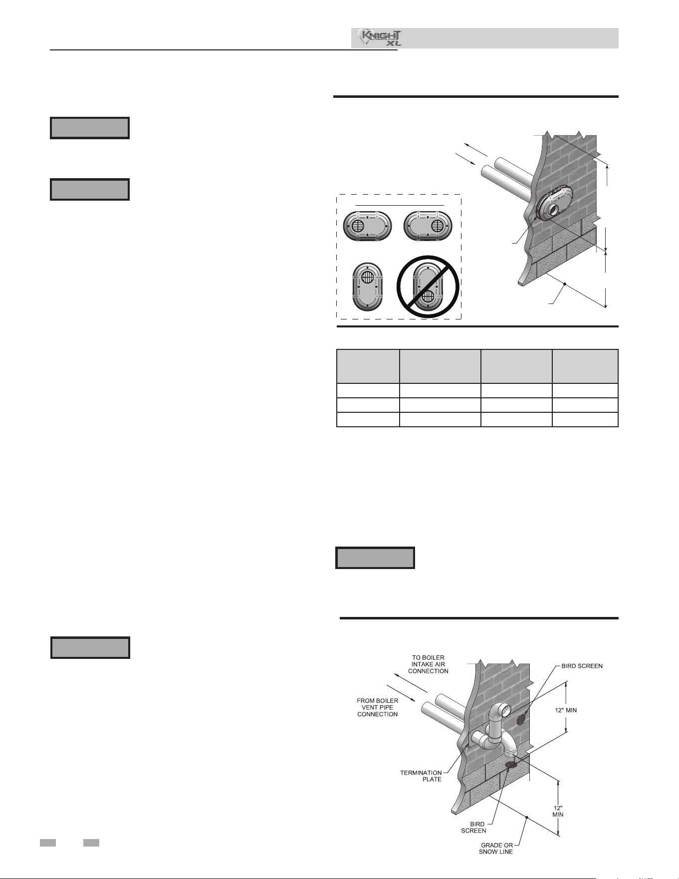
26
4 Sidewall direct venting
Vent/air termination – sidewall
Follow instructions below when
determining vent location to avoid
possibility of severe personal injury, death,
or substantial property damage.
A gas vent extending through an exterior
wall shall not terminate adjacent to a
wall or below building extensions such
as eaves, parapets, balconies, or decks.
Failure to comply could result in severe
personal injury, death, or substantial
property damage.
⚠ WARNING
⚠ WARNING
Determine location
Locate the vent/air terminations using the following
guidelines:
1. e total length of piping for vent or air must not exceed
the limits given in the General Venting Section of this
manual.
2. You must consider the surroundings when terminating
the vent and air:
a. Position the vent termination where vapors will
not damage nearby shrubs, plants or air
conditioning equipment or be objectionable.
b. e ue products will form a noticeable plume as
they condense in cold air. Avoid areas where the
plume could obstruct window views.
c. Prevailing winds could cause freezing of
condensate and water/ice buildup where ue
products impinge on building surfaces or plants.
d. Avoid possibility of accidental contact of ue
products with people or pets.
e. Do not locate the terminations where wind eddies
could aect performance or cause recirculation,
such as inside building corners, near adjacent
buildings or surfaces, window wells, stairwells,
alcoves, courtyards, or other recessed areas.
⚠ WARNING
Sidewall vent and air inlet terminations
must terminate in the same pressure
zone.
f. Do not terminate above any door or window.
Condensate can freeze, causing ice formations.
g. Locate or guard vent to prevent condensate damage
to exterior nishes.
TO BOILER
INTAKE AIR
CONNECTION
FROM BOILER
VENT PIPE
CONNECTION
VENT / AIR
TERMINATION
GRADE OR
SNOW LINE
12"
MIN
12"
MIN
TO
OVER
-
HANG
POSSIBLE ORIENTATIONS
Figure 4-1A PVC/CPVC/Polypropylene Sidewall
Termination of Air and Vent
Table 4A Sidewall Vent Kits
Do not exceed the maximum lengths of the
outside vent piping shown in FIG. 4-1B.
Excessive length exposed to the outside could
cause freezing of condensate in the vent pipe,
resulting in potential boiler shutdown.
⚠ WARNING
If using the alternate sidewall termination:
3. e air piping must terminate in a down-turned elbow as
shown in FIG. 4-1B. is arrangement avoids recirculation
of ue products into the combustion air stream.
4. e vent piping must terminate in an elbow pointed outward
or away from the air inlet, as shown in FIG. 4-1B.
Figure 4-1B Alternate PVC/CPVC/ Polypropylene Sidewall
Termination of Air and Vent w/Field Supplied Fittings
Installation & Operation Manual
Model Kit Number Air Intake Vent Size
400 - 500 100157611 4" 4" vent
650 - 800 100157613 4" 6" vent
1000 100157612 6" 6" vent
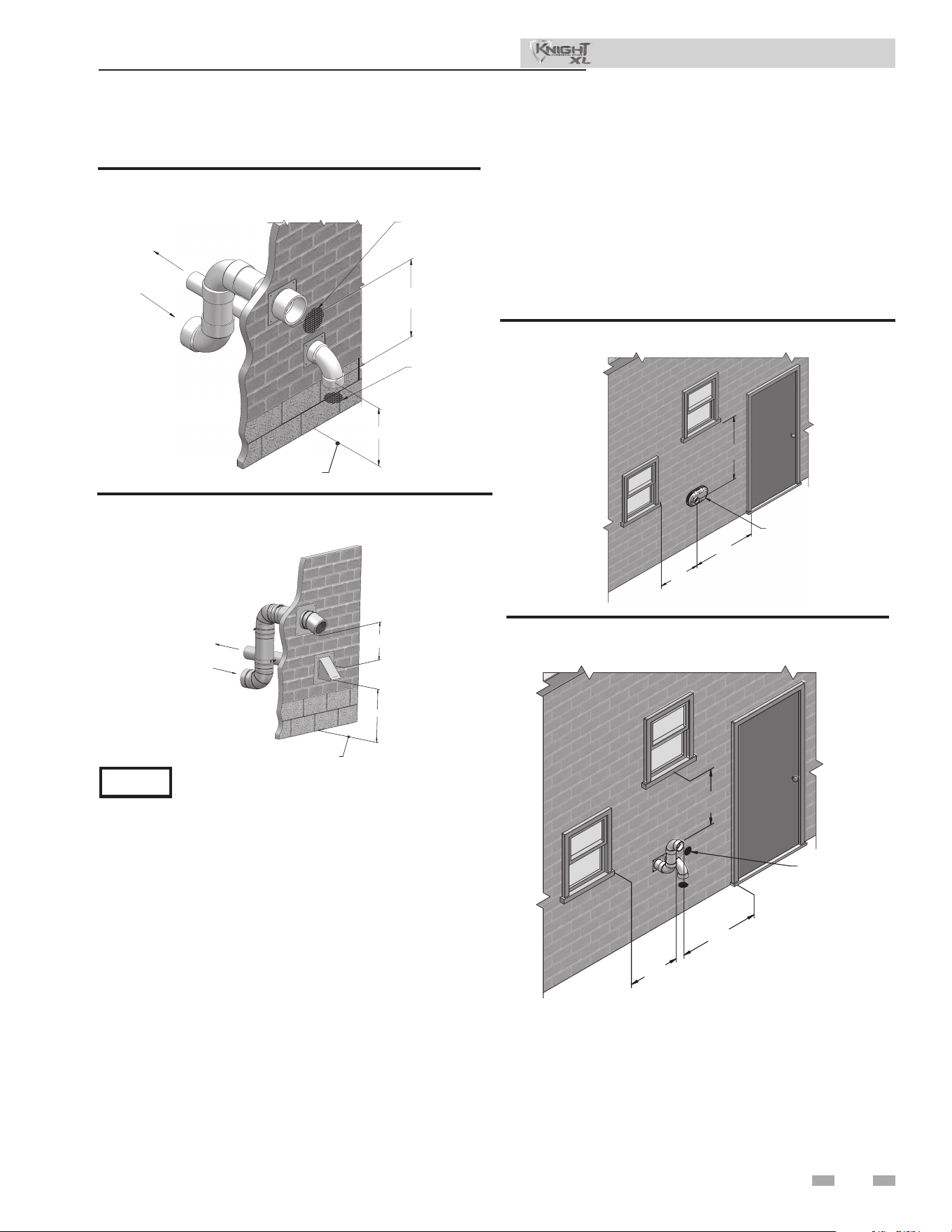
4 Sidewall direct venting
TO BOILER INTAKE
AIR CONNECTION
FROM BOILER VENT
PIPE CONNECTION
12" (305 MM) MIN
12" (305 MM) MIN
GRADE OR
SNOW LINE
Figure 4-2B Alternate Stainless Steel Sidewall Termination
w/Field Supplied Fittings
12" (305 MM) MIN
12" (305 MM) MIN
FROM BOILER
VENT PIPE
CONNECTION
TO BOILER
INTAKE AIR
CONNECTION
BIRD SCREEN
BIRD SCREEN
GRADE OR
SNOW LINE
Figure 4-2A Alternate PVC/CPVC/ Polypropylene
Sidewall Termination w/Field Supplied Fittings
PVC/CPVC or ABS is acceptable air inlet pipe material.
NOTICE
Vent/air termination – sidewall
5. Maintain clearances as shown in FIG.’s 4-1A thru 4-4B.
Also maintain the following:
a. Vent must terminate:
• At least 6 feet (1.8 m) from adjacent walls.
• No closer than 12 inches (305 mm) below roof
overhang.
• At least 7 feet (2.1 m) above any public walkway.
• At least 3 feet (.9 m) above any forced air intake
within 10 feet (3 m).
• No closer than 12 inches (305 mm) below or
horizontally from any door or window or any other
gravity air inlet.
b. Air inlet must terminate at least 12 inches (305 mm)
above grade or snow line; at least 12 inches (305 mm)
below the vent termination (FIG. 4-1B); and the vent
pipe must not extend more than 24 inches (610 mm)
vertically outside the building.
VENT / AIR
TERMINATION
4'
MIN.
12"
MIN.
12"
MIN.
Figure 4-3A Clearance to Gravity Air Inlets
BIRD
SCREEN
(TYPICAL)
4'
MIN.
12”
MIN.
12”
MIN.
Figure 4-3B Alternate Clearance to Gravity Air Inlets
w/Field Supplied Fittings
27
Installation & Operation Manual
c. Do not terminate closer than 4 feet (1.2 m)
horizontally from any electric meter, gas meter,
regulator, relief valve, or other equipment. Never
terminate above or below any of these within 4 feet
(1.2 m) horizontally.
6. Locate terminations so they are not likely to be damaged by
foreign objects, such as stones or balls, or subject to buildup
of leaves or sediment.
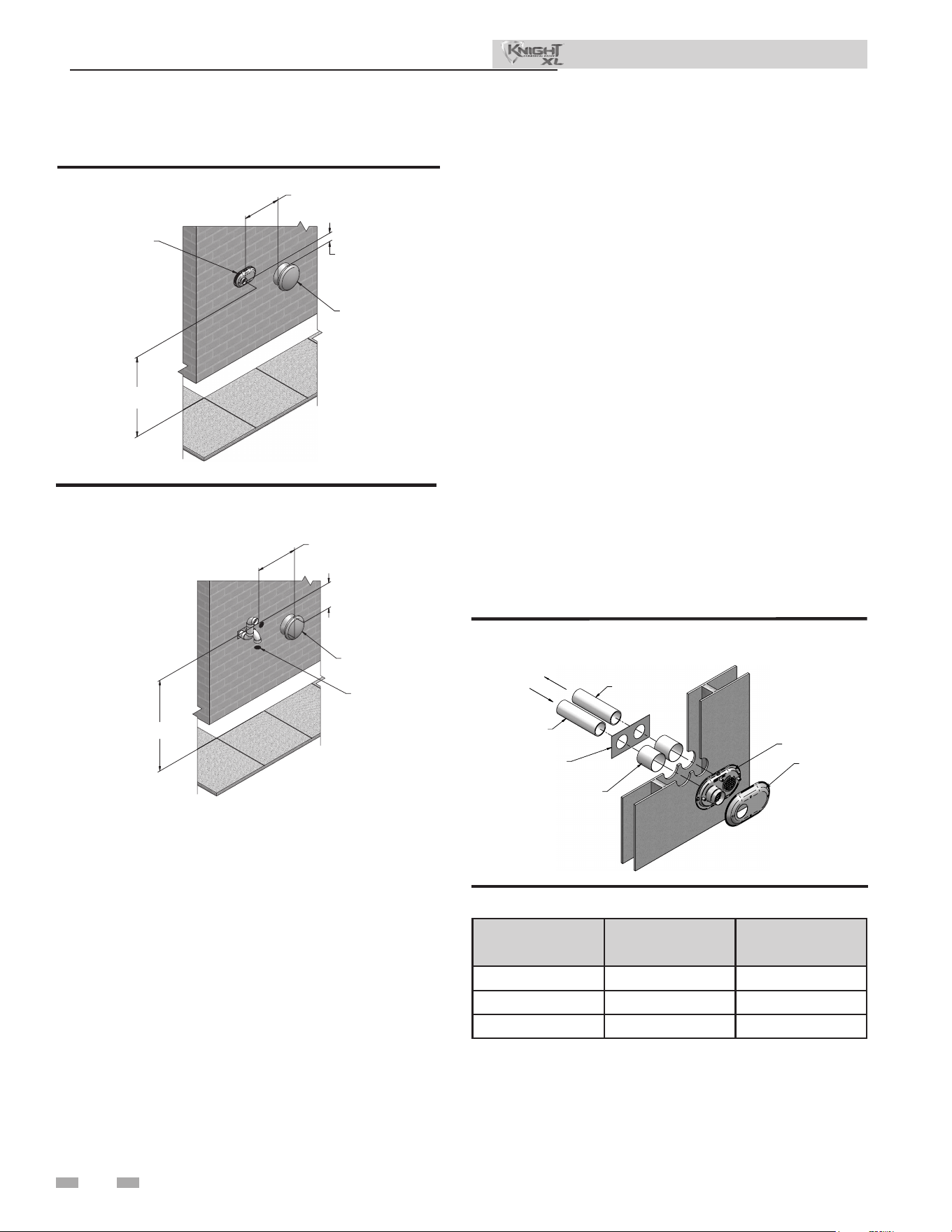
28
36” (914 MM)
MIN
7’ (2.1 M) MIN ABOVE ANY
PUBLIC WALKWAY
IF LESS
THAN 10’ (3 M)
FORCED AIR
INLET
BIRD
SCREEN
(TYPICAL)
Figure 4-4B Alternate Clearance to Forced Air Inlets
w/Field Supplied Fittings
4 Sidewall direct venting (continued)
Vent/air termination – sidewall
FORCED AIR
INLET
VENT / AIR
TERMINATION
7' MIN. ABOVE ANY
PUBLIC WALKWAY
IF LESS
THAN 10’
36"
MIN.
Figure 4-4A Clearance to Forced Air Inlets
Figure 4-5A PVC/CPVC Sidewall Termination Assembly
Prepare wall penetrations
1. Use the factory supplied wall plate as a template to locate
the vent and air intake holes and mounting holes.
Air pipe penetration:
a. Cut a hole for the air pipe. Size the air pipe hole as
close as desired to the air pipe outside
diameter.
Vent pipe penetration:
a. Cut a hole for the vent pipe. For either combustible or
noncombustible construction, size the vent pipe hole
with at least a 1/2 inch clearance around the vent pipe
outer diameter:
• 5½ inch hole (140 mm) hole for 4 inch (102 mm)
vent pipe
• 7½ inch hole (191 mm) hole for 6 inch (152 mm)
vent pipe
Drill 3/16" diameter holes for inserting the plastic anchors
into the wall.
Installation & Operation Manual
2. For Polypropylene Only: Install the vent and air intake
sidewall adapters from Table 3H into the vent plate. Slide
the sidewall retaining bracket down the sidewall adapters
ush to the vent plate (FIG. 4-4B).
3. For PVC/CPVC Only: Install the vent and air intake
piping through the wall into the vent plate openings.
Use RTV silicone sealant to seal the air pipe. Use the
cement/primer listed in Table 3H to seal the vent pipe.
3. Mount and secure the vent plate to the wall using stainless
steel screws.
5. Seal all gaps between the pipes and wall. Seal around the
plate to the wall assuring no air gaps.
6. Assemble the vent cap to the vent plate (see FIG.’s 4-5A
and 4-5B). Insert the stainless steel screws into the vent
cap screw hole openings and securely attach the vent cap
to the vent plate.
7. Seal all wall cavities.
8. PVC/CPVC terminations are designed to accommodate any
wall thickness of standard constructions per the directions
found in this manual.
9. Stainless steel terminations are designed to penetrate walls
with a thickness up to 9.25 inches of standard construction.
Model Air Vent
400 - 500 4" 4"
650 - 800 4" 6"
1000 6" 6"
Table 4B Sidewall Vent Centerline Dimensions
VENT PIPING
GALVANIZED
THIMBLE
VENT CAP
AIR PIPING
WALL PLATE
VENT PLATE
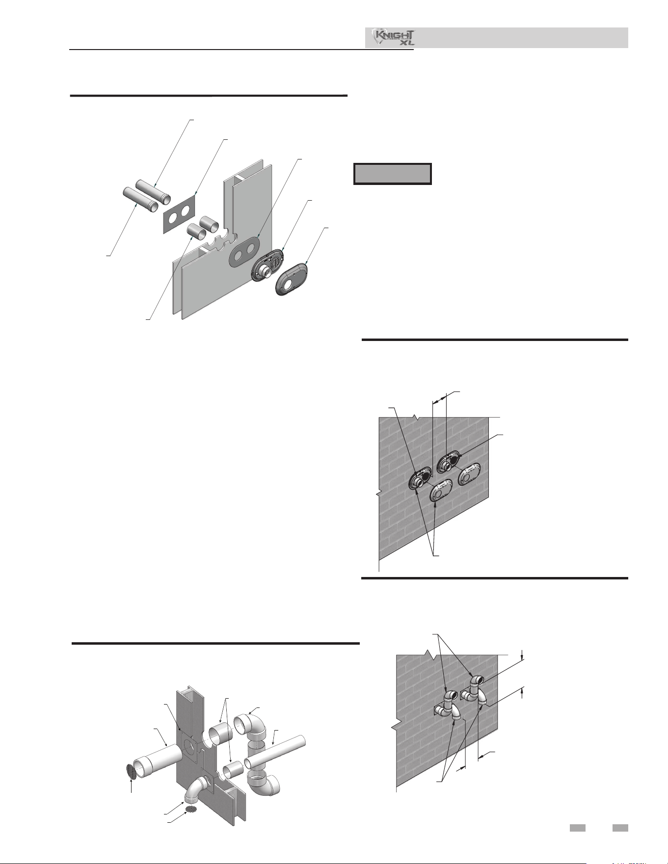
29
4 Sidewall direct venting
SIDEWALL
TERMINATION PLATE
VENT
PIPING
GALVANIZED
THIMBLE
(WHEN REQUIRED BY LOCAL CODES)
ELBOW
ELBOW
AIR PIPING
BIRD SCREEN
BIRD SCREEN
Figure 4-5C A Typical Sidewall Termination Assembly - PVC/
CPVC/ Polypropylene or Stainless Steel
All vent pipes and air inlets must terminate
at the same height to avoid possibility of
severe personal injury, death, or substantial
property damage.
Multiple vent/air terminations
1. When terminating multiple Knight XL’s terminate
each vent/air connection as described in this manual
(FIG. 4-6A).
2. Place wall penetrations to obtain minimum clearance of
12 inches (305 mm) between vent pipe and adjacent air
inlet elbow, as shown in FIG. 4-6A for U.S. installations.
For Canadian installations, provide clearances required by
CSA B149.1 Installation Code.
3. e air inlet of a Knight XL is part of a direct vent
connection. It is not classied as a forced air intake with
regard to spacing from adjacent boiler vents.
VENT
12" (305 MM) MIN
12" (305 MM) MIN. BETWEEN EDGE
OF AIR PIPE AND ADJACENT VENT
PIPE
AIR
Figure 4-6B Alternate Multiple Vent Terminations
w/Field Supplied Fittings (must also comply with
Figure 4-1B)
⚠ WARNING
Prepare wall penetrations (Alternate - Field
Supplied Option)
1. Air pipe penetration:
a. Cut a hole for the air pipe. Size the air pipe hole as
close as desired to the air pipe outside diameter.
2. Vent pipe penetration:
a. Cut a hole for the vent pipe. For either combustible
or noncombustible construction, size the vent pipe
hole with at least a 1/2 inch clearance around the vent
pipe outer diameter:
• 5½ inch hole (140 mm) hole for 4 inch (102 mm)
vent pipe
• 7½ inch hole (191 mm) hole for 6 inch (152 mm)
vent pipe
b. Insert a galvanized metal thimble in the vent pipe
hole as shown in FIG. 4-5C.
3. Use a sidewall termination plate as a template for correct
location of hole centers.
4. Follow all local codes for isolation of vent pipe when passing
through oors or walls.
5. Seal exterior openings thoroughly with exterior caulk.
12" MIN. BETWEEN EDGE OF AIR
INLET AND ADJACENT VENT OUTLET
VENT / AIR
TERMINATION
VENT
AIR
Figure 4-6A Multiple Vent Terminations (must also
comply with Figure 4-1A)
Installation & Operation Manual
SIDEWALL
ADAPTER
(AIR)
SIDE
WALL
A
DAPTER
(V
ENT)
WALL
PLATE
GALVANIZED
THIMBLE
SIDEWALL
RETAINING
PLATE
VENT
PLATE
VENT
CAP
IMG00085
Figure 4-5B Polypropylene Sidewall Termination Assembly
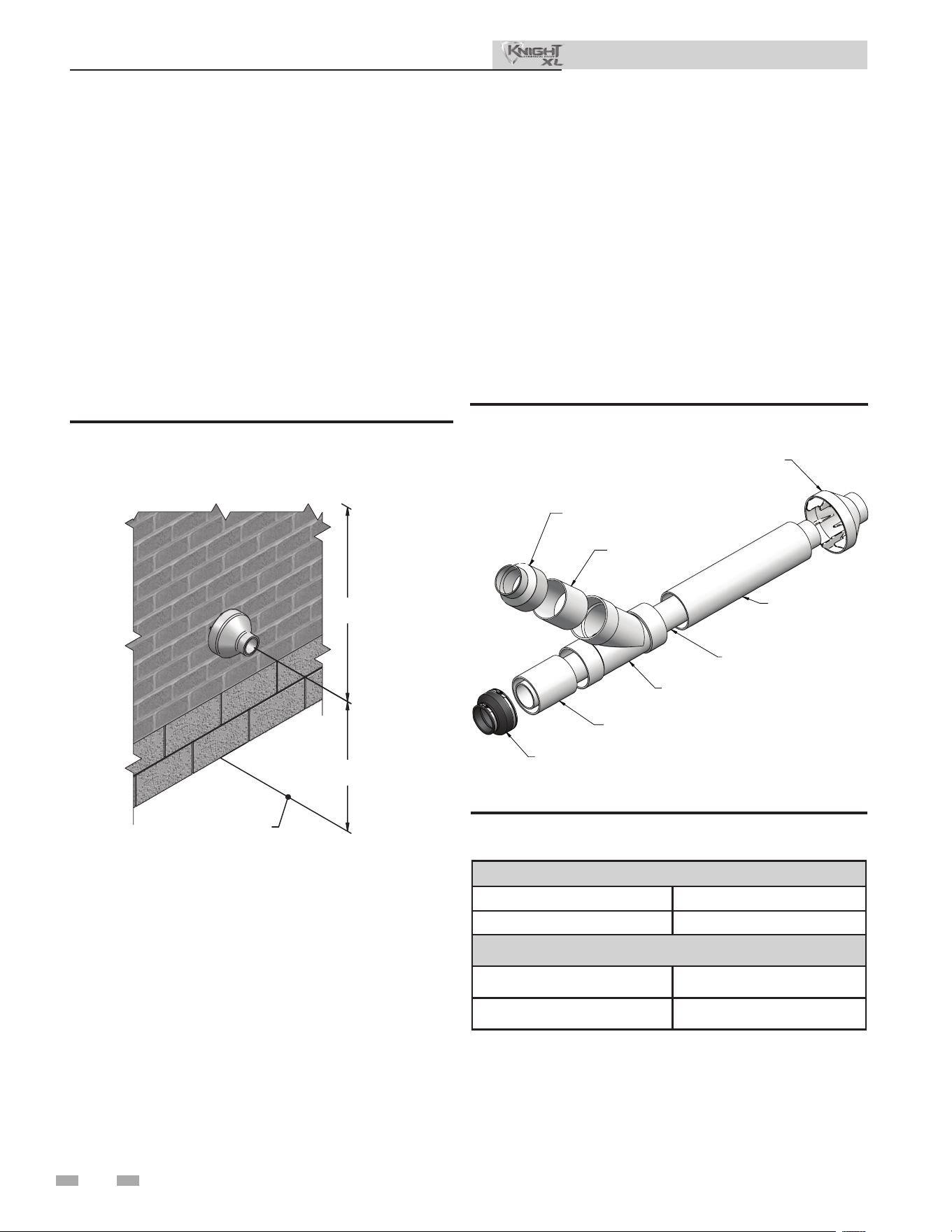
30
4 Sidewall direct venting (continued)
4" (102 MM) DIA.
6" (152 MM) DIA.
RAIN CAP
"Y" CONCENTRIC
FITTING
"FLEXIBLE" PIPE
COUPLING
6" (152 MM) DIA.
6" (152 MM) DIA.
6" (152 MM) TO 4" (102 MM) REDUCER
Figure 4-8 Kit Contents_100140484 - Models 400 - 500
Sidewall termination installation
1. Determine the best location for the termination kit
(see FIG. 4-7).
2. Reference the Determine Location Section of this manual
for general termination considerations.
3. Cut one (1) hole 7 inch (178 mm) diameter for #100140484
installations into the structure to install the termination kit.
4. Partially assemble the concentric vent termination kit.
Clean and cement using the procedures found in these
instructions.
a. Cement the Y concentric tting to the larger kit pipe
(FIG. 4-8).
b. Cement the rain cap to the smaller diameter kit pipe
(FIG. 4-8).
Sidewall termination – optional concentric vent: Models 400 - 500 Only
Description and usage
Lochinvar oers an optional concentric combustion air
and vent pipe termination kit (#100140484 for 4" (102 mm)
diameter - Models 400 - 500). Both combustion air and vent
pipes must attach to the termination kit. e termination kit
must terminate outside the structure and must be installed as
shown below in FIG. 4-7.
e required combustion vent pipe materials are listed in
Table 3H of this manual.
OVERHANG
OR ROOF
12" (305 MM)
MIN
12" (305 MM)
MIN
GRADE / SNOW LINE
Figure 4-7 Concentric Sidewall Termination
Installation & Operation Manual
Roof Terminations
Size Part No.
4" ICRT4679
Wall Terminations
Size Part No.
4" ICWT462
Table 4C Alternate Centrotherm Concentric Vent
Terminations
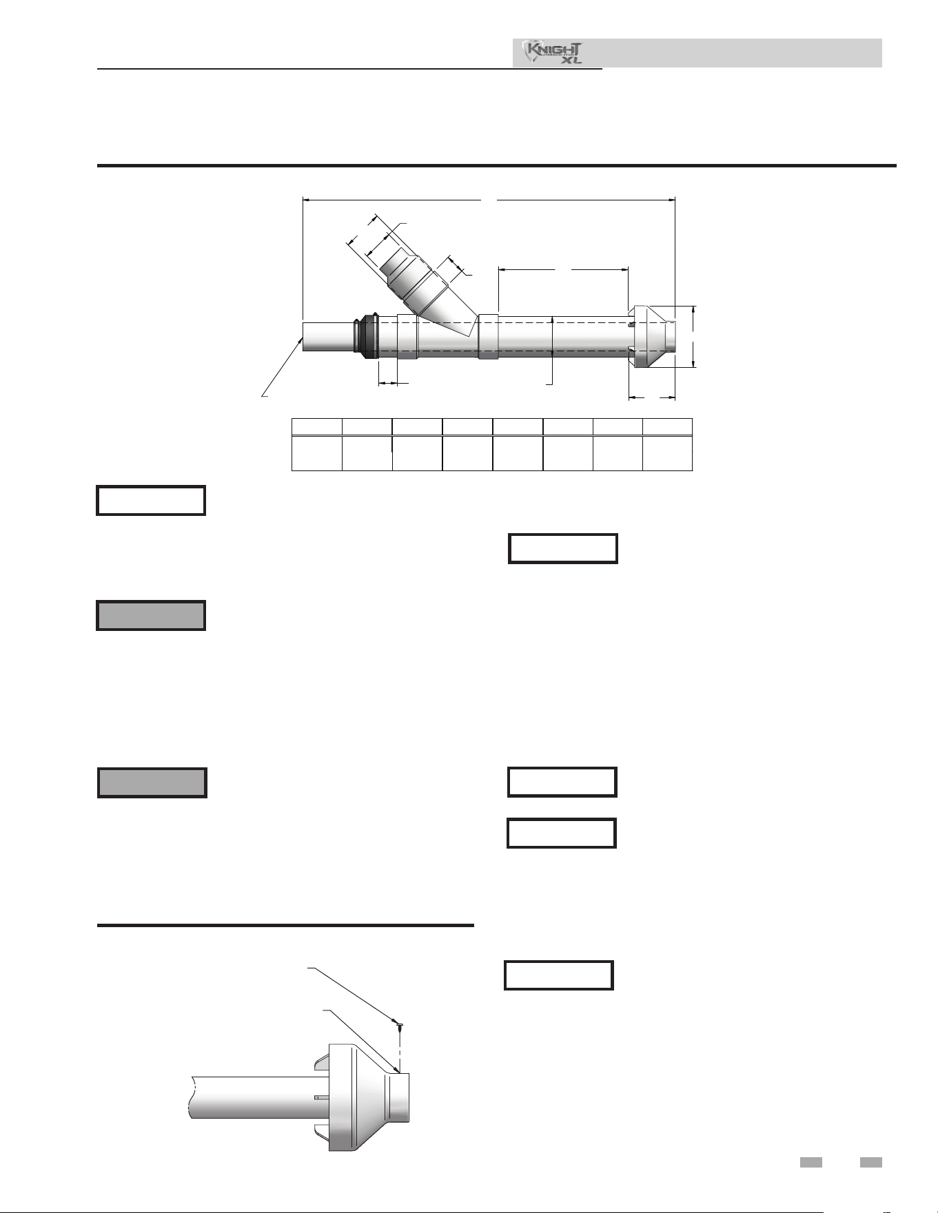
31
4 Sidewall direct venting
Sidewall termination – optional concentric vent: Models 400 - 500 Only
Figure 4-9 Concentric Vent Dimensional Drawing - Models 400 - 500
Instead of cementing the smaller pipe
to the rain cap, a eld-supplied stainless
steel screw may be used to secure the
two (2) components together when eld
disassembly is desired for cleaning (see FIG.
4-10).
When using the alternate screw assembly
method, drill a clearance hole in the rain
cap and a pilot hole in the vent pipe for
the screw size being used. Failure to drill
adequate holes may cause cracking of PVC
components, allowing combustion products
to be recirculated. Failure to follow this
warning could result in personal injury or
death.
Do not operate the appliance with the rain
cap removed or recirculation of combustion
products may occur. Water may also collect
inside the larger combustion air pipe and
ow to the burner enclosure. Failure to
follow this warning could result in product
damage or improper operation, personal
injury, or death.
STAINLESS STEEL SCREW
(FIELD SUPPLIED)
DRILL CLEARANCE HOLE IN
RAIN CAP & PILOT HOLE
IN VENT PIPE
Figure 4-10 Rain Cap to Vent Pipe Alternate Assembly
5. Install the Y concentric tting and pipe assembly through
the structure’s hole from an inside wall.
Do not allow insulation or other materials
to accumulate inside the pipe assembly
when installing through the hole.
6. Install the rain cap and small diameter pipe assembly
into the Y concentric tting and large pipe assembly
from an outside wall. Ensure small diameter pipe is
fastened tightly into the rubber adapter for #100140484
installations.
7. Secure the assembly to the structure as shown in
FIG. 4-11 using eld-supplied metal strapping or
equivalent support material.
Ensure termination location clearance
dimensions are as shown in FIG. 4-7.
If assembly needs to be extended to
allow sidewall thickness requirement, the
two (2) pipes supplied in the kit may
be replaced by using the same diameter,
eld-supplied standard schedule 40 PVC.
Do not extend dimension D* more than
60 inches (1524 mm) (see FIG. 4-9).
NOTICE
⚠ WARNING
⚠ WARNING
NOTICE
NOTICE
NOTICE
If assembly depth needs to be reduced,
dimension D can be as short as possible.
NOTICE
"B" DIA. PVC
VENT / EXHAUST
"A"
"H" DIA.
"D"
"E"
"F"
"G"
3"
(76 MM)
ABCDEFGH
60"4"6"21 1/8" 10" 7 5/8" 3" 6 5/8"
"C" DIA.
"B" DIA.
(1524 MM)
(102 MM)
(152 MM)
(537 MM)
(254 MM)(194 MM)
(76 MM)
(168 MM)
Installation & Operation Manual
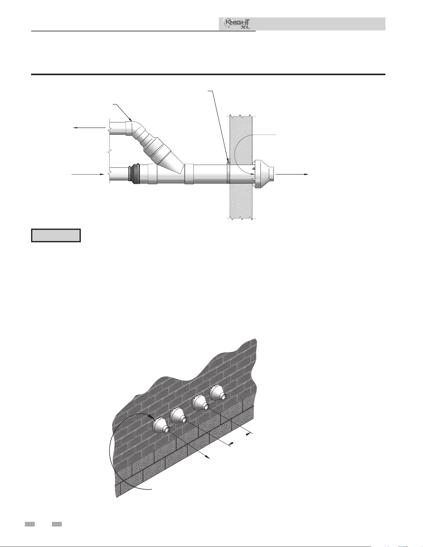
32
4 Sidewall direct venting (continued)
Sidewall termination – optional concentric vent: Models 400 - 500 Only
Multiventing sidewall terminations
When two (2) or more direct vent appliances are vented
near each other, each appliance must be individually vented
(see FIG. 4-12). NEVER common vent or breach vent this
appliance. When two (2) or more direct vent appliances are
vented near each other, two (2) vent terminations may be
installed as shown in FIG. 4-12. It is important that vent
terminations be made as shown to avoid recirculation of ue
gases.
VENT
COMBUSTION
AIR
12"
MINIMUM
Figure 4-12 Concentric Vent and Combustion Air Termination
COMBUSTION AIR
VENT
VENT
COMBUSTION AIR
STRAP
(FIELD SUPPLIED)
ELBOW
(FIELD SUPPLIED)
Figure 4-11 Concentric Vent Sidewall Attachment
DO NOT use eld-supplied couplings
to extend pipes. Airow restriction
will occur and may cause intermittent
operation.
8. Cement appliance combustion air and vent pipes to the
concentric vent termination assembly. See FIG. 4-11 for
proper pipe attachment.
9. Operate the appliance one (1) heat cycle to ensure
combustion air and vent pipes are properly connected
to the concentric vent termination connections.
CAUTION
Installation & Operation Manual
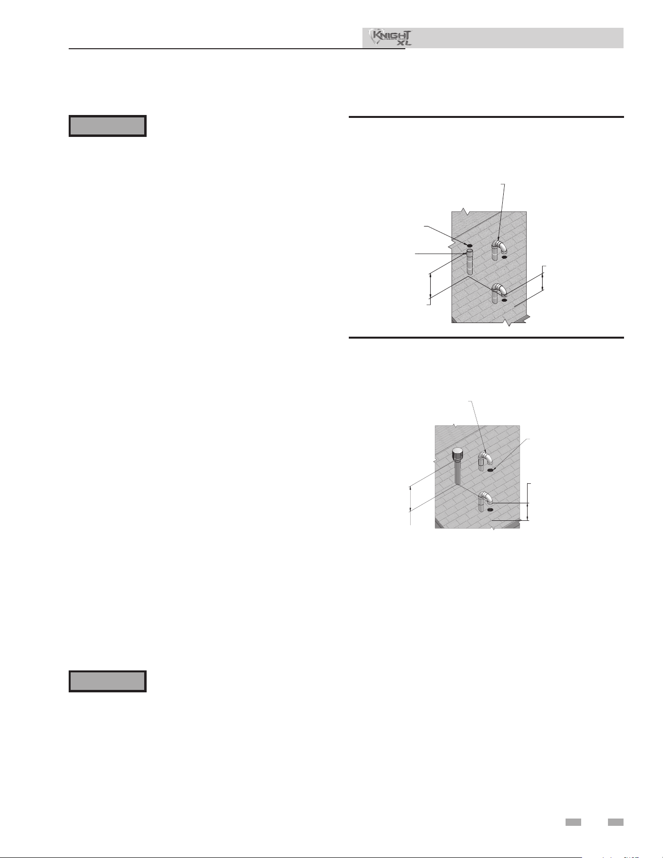
33
5 Vertical direct venting
Vent/air termination – vertical
Follow instructions below when
determining vent location to avoid
possibility of severe personal injury, death
or substantial property damage.
Determine location
Locate the vent/air terminations using the following
guidelines:
1. e total length of piping for vent or air must not exceed
the limits given in the General Venting Section of this
manual.
2. Prepare the vent termination and the air termination
elbow (FIG. 5-1A) by inserting bird screens.
3. e vent must terminate at least 3 feet above the highest
place in which the vent penetrates the roof and at least
2 feet above any part of a building within 10 horizontal
feet.
4. e air piping must terminate in a down-turned 180°
return pipe no further than 2 feet (.6 m) from the center
of the vent pipe. is placement avoids recirculation of
ue products into the combustion air stream.
5. e vent piping must terminate in an up-turned coupling
as shown in FIG. 5-1A. e top of the coupling must
be at least 1 foot above the air intake. When the vent
termination uses a rain cap as illustrated in FIG. 5-1B
maintain at least 36" (914 mm) above the air inlet. e
air inlet pipe and vent pipe can be located in any desired
position on the roof, but must always be no further than
2 feet (.6 m) apart and with the vent termination at least
1 foot above the air intake.
6. Maintain the required dimensions of the nished
termination piping as shown in FIG. 5-1A.
7. Do not extend exposed vent pipe outside of building
more than shown in this document. Condensate could
freeze and block vent pipe.
ALTERNATE INTAKE LOCATIONS:
INTAKE PIPES MAY BE LOCATED
ANYWHERE WITHIN 24" (610 MM)
OF VENT PIPE
BIRD SCREEN
(TYPICAL)
COUPLING
(FIELD SUPPLIED)
VENT OUTLET
12" MINIMUM
ABOVE AIR INLET
6" (152 MM) MINIMU
M
ABOVE ROOF /
SNOW LINE
VENT
COMBUSTION
AIR
Figure 5-1A PVC/CPVC/Polypropylene Vertical
Termination of Air and Vent
8. Locate terminations so they are not likely to be damaged by
foreign objects, such as stones or balls, or subject to buildup
of leaves or sediment.
⚠ WARNING
⚠ WARNING
Rooop vent and air inlet terminations
must terminate in the same pressure zone,
unless vertical vent sidewall air is set up as
shown in the General Venting - Vertical
Vent, Sidewall Air Section.
6" (152 MM) MINIMUM
ABOVE ROOF /
SNOW LINE
VENT
COM,BUSTION
AIR
ALTERNATE INTAKE LOCATIONS:
INTAKE PIPES MAY BE LOCATED
ANYWHERE WITHIN 24” (610 MM)
OF VENT PIPE
VENT OUTLET
36” (914 MM) MINIMUM
ABOVE AIR INLET
BIRD SCREEN
(TYPICAL)
Figure 5-1B Stainless Steel Vertical Termination of Air
and Vent
Installation & Operation Manual
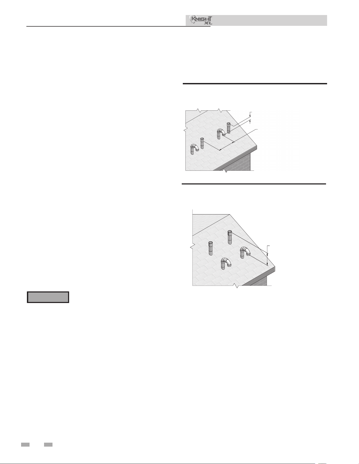
34
5 Vertical direct venting (continued)
Vent/air termination – vertical
Prepare roof penetrations
1. Air pipe penetration:
a. Cut a hole for the air pipe. Size the air pipe hole as
close as desired to the air pipe outside diameter.
2. Vent pipe penetration:
a. Cut a hole for the vent pipe. For either combustible
or noncombustible construction, size the vent pipe
hole with at least a 1/2 inch clearance around the
vent pipe outer diameter:
• 5½ inch hole (140 mm) hole for 4 inch (102 mm)
vent pipe
• 7½ inch hole (191 mm) hole for 6 inch (152 mm)
vent pipe
b. Insert a galvanized metal thimble in the vent pipe
hole (when required by local codes).
3. Space the air and vent holes to provide the minimum
spacing shown in FIG.’s 5-1A and 5-1B.
4. Follow all local codes for isolation of vent pipe when
passing through oors, ceilings, and roofs.
5. Provide ashing and sealing boots sized for the vent pipe
and air pipe.
Multiple vent/air terminations
1. When terminating multiple Knight XL boilers, terminate
each vent/air connection as described in this manual
(FIG. 5-2).
Terminate all vent pipes at the same
height and all air pipes at the same height
to avoid recirculation of ue products and
the possibility of severe personal injury,
death, or substantial property damage.
2. Place roof penetrations to obtain minimum clearance
of 12 inches (305 mm) between edge of air intake
elbow and adjacent vent pipe of another boiler for U.S.
installations (see FIG. 5-2). For Canadian installations,
provide clearances required by CSA B149.1 Installation
Code.
3. e air inlet of a Knight XL boiler is part of a direct vent
connection. It is not classied as a forced air intake with
regard to spacing from adjacent boiler vents.
12" (305 MM) MINIMUM
VERTICALLY FROM VENT
OUTLET TO ANY AIR INLET
12" (305 MM) MINIMUM FROM EDGE
OF AIR INTAKE PIPE TO ADJACENT
VENT PIPE FROM ANOTHER BOILER
AIR
AIR
VENT
VENT
Figure 5-2 Vertical Terminations with Multiple Boilers
VENT
VENT
AIR
AIR
12" (305 MM) MINIMUM
VERTICALLY FROM VENT
OUTLET TO ANY AIR INLET
Figure 5-3 Alternate Vertical Terminations with Multiple
Boilers
⚠ WARNING
Installation & Operation Manual
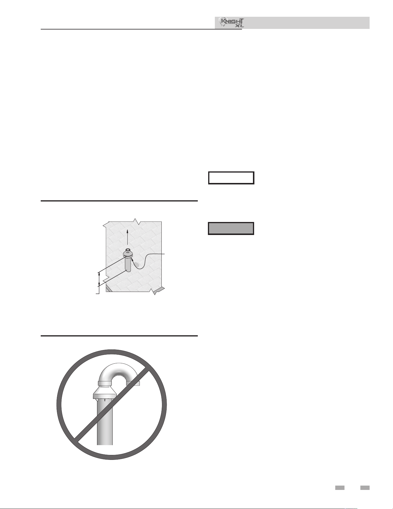
35
5 Vertical direct venting
Vertical termination – optional concentric vent: Models 400 - 500 Only
Description and usage
Lochinvar oers an optional concentric combustion air and
vent pipe termination kit. Both combustion air and vent
pipes must attach to the termination kit. e termination kit
must terminate outside the structure and must be installed as
shown in FIG. 5-4.
Field supplied pipe and ttings are required to complete the
installation.
e required combustion vent pipe ttings are listed in
Table 3H.
Vertical termination installation
1. See Section 5, Vertical Direct Venting - Determine
Location (where applicable).
Instead of cementing the smaller pipe
to the rain cap, a eld supplied stainless
steel screw may be used to secure the
two (2) components together when eld
disassembly is desired for cleaning (see
FIG. 4-10).
When using the alternate screw assembly
method, drill a clearance hole in the rain
cap and a pilot hole in the vent pipe for
the screw size being used. Failure to drill
adequate holes may cause cracking of PVC
components, allowing combustion products
to be recirculated. Failure to follow this
warning could result in personal injury or
death.
2. Cut one (1) hole (7 inch (178 mm) diameter for #100140484
installations) into the structure to install the termination
kit.
3. Partially assemble the concentric vent termination kit.
Clean and cement following the cleaning procedures in
these instructions.
a. Cement the Y concentric tting to the larger
diameter kit pipe (see FIG. 4-8).
b. Cement rain cap to the smaller diameter kit pipe (see
FIG. 4-8).
VENT
COMBUSTION
AIR
12" (305 MM) (18" (457 MM)
FOR CANADA) MINIMUM
CLEARANCE ABOVE HIGHEST
A
NTICIPATED SNOW
LEVEL. MAXIMUM OF
24" (610 MM) ABOVE ROOF.
Figure 5-4 Concentric Vertical Termination
NOTICE
⚠ WARNING
Figure 5-5 Do Not Install U-Bend to Rain Cap
Installation & Operation Manual
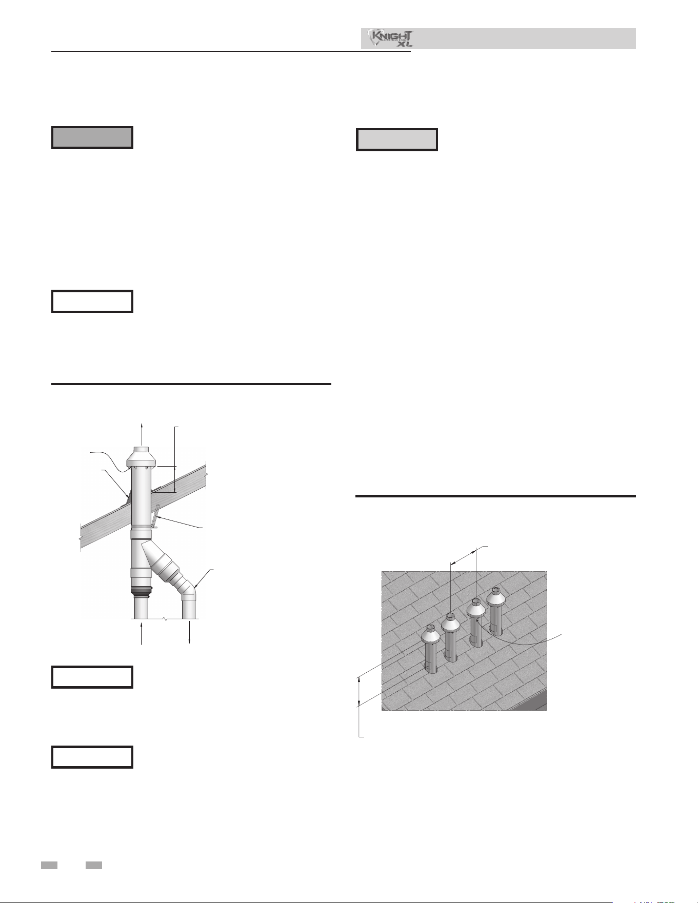
36
5 Vertical direct venting (continued)
Vertical termination – optional concentric vent: Models 400 - 500 Only
ELBOW
(FIELD SUPPLIED)
SUPPORT
(FIELD SUPPLIED)
ROOF BOOT
/
FLASHIN
G
(FIELD SUPPLIED)
VENT
COMBUSTION
AIR
VENT
12" (305 MM) (18" (457 MM) FOR CANADA)
MINIMUM CLEARANCE ABOVE HIGHEST
ANTICIPAT
ED SNOW LEVEL. MAXIMUM OF
24” (610 MM) ABOVE ROOF.
COMBUSTION
AIR
Figure 5-6 Concentric Vent Roof Installation
Ensure termination height is above the
roof surface or anticipated snow level
(12 inches (305 mm) in U.S.A. or 18
inches (457 mm) in Canada) as shown in
FIG. 5-4.
If assembly is too short to meet height
requirement, the two (2) pipes supplied
in the kit may be replaced by using the
same diameter, eld supplied standard
schedule 40 PVC for 100140484. Do
not extend dimension D* more than 60
inches (1524 mm) (see FIG. 4-9).
CAUTION
DO NOT use eld-supplied couplings
to extend pipes. Airow restriction will
occur.
6. Install the rain cap and the small diameter pipe assembly
into the roof penetration assembly. Ensure the small
diameter pipe is fastened tightly into the rubber adapter
for #100140484 installations.
7. Cement the appliance combustion air and vent pipes to
the concentric vent termination assembly. See FIG. 5-6
for proper pipe attachment.
8. Operate the appliance through one (1) heat cycle to ensure
combustion air and vent pipes are properly connected to
the concentric vent termination connections.
Multiventing vertical terminations
When two (2) or more direct vent appliances are vented
near each other, each appliance must be individually vented
(see FIG. 5-7). NEVER common vent or breach vent this
appliance. When two (2) or more direct vent appliances
are vented near each other, two (2) vent terminations may
be installed as shown in FIG. 5-7. It is important that vent
terminations be made as shown to avoid recirculation of ue
gases.
12”
MINIMUM
12” (18” FOR CANADA)
MINIMUM CLEARANCE
ABOVE HIGHEST
ANTICIPATED SNOW
LEVEL. MAXIMUM OF
24” ABOVE ROOF.
COMBUSTION
AIR (TYPICAL)
Figure 5-7 Concentric Vent and Combustion Air Vertical
Termination
Do not operate the appliance with
the rain cap removed or recirculation
of combustion products may occur.
Water may also collect inside the larger
combustion air pipe and ow to the
burner enclosure. Failure to follow this
warning could result in product damage
or improper operation, personal injury,
or death.
4. Install the Y concentric tting pipe assembly up through
the structure’s hole and eld supplied roof boot/ashing.
Do not allow insulation or other materials
to accumulate inside the pipe assembly
when installing through the hole.
5. Secure the assembly to the roof structure as shown
below in FIG. 5-6 using eld supplied metal strapping or
equivalent support material.
⚠ WARNING
NOTICE
NOTICE
NOTICE
Installation & Operation Manual
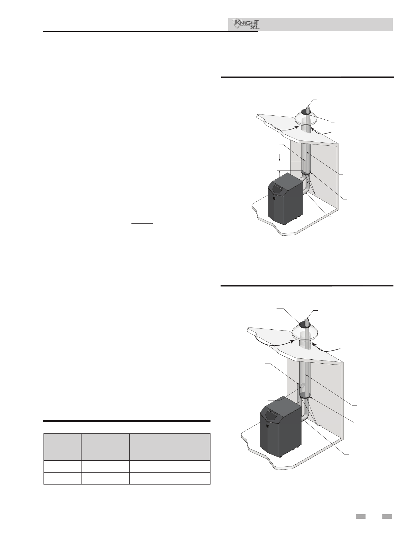
37
5 Vertical direct venting
Alternate vertical concentric venting
is appliance may be installed with a concentric vent
arrangement where the vent pipe is routed through an
existing unused venting system; or by using the existing
unused venting system as a chase for vent and combustion
air routing.
Concentric Venting Arrangement
e venting is to be vertical through the roof. e annular
space between the O.D. of the vent pipe and the I.D. of the
existing unused venting system is utilized for the combustion
air source.
e minimum size of the existing vent system required to
achieve enough annular space for combustion air can be
found in Table 5A.
e upper and lower termination as well as any other unsealed
joints in the existing vent system must be sealed to ensure that
all combustion air is drawn from under the vent cap as shown
in FIG.’s 5-8 and 5-9.
Approved venting materials must be used as specied in
Table 3H.
Follow all vent / air termination and clearance requirements
per this section to the appropriate example. Installation must
comply with local requirements and with the National Fuel
Gas Code.
e maximum allowable equivalent vent and air intake
lengths for this venting arrangement are to be determined
from the General Venting Section.
If an existing unused venting system is converted for use
with this method of concentric venting, the installer must
ensure that the existing venting system is clean and free from
particulate contamination that will harm this appliance and
cause increased nuisance calls or maintenance. See Table 1A
for a list of corrosive contaminants and sources.
Two example scenarios of a concentric venting arrangement
are shown for illustrative purposes in FIG.’s 5-8 and 5-9.
Figure 5-8 Concentric Vent Example 1
DIR #2000585169 00
FLUE EXHAUST
SEAL
COMBUSTION AIR
AIRINLET
W/ SCREEN
12"
MIN.
EXISTING
SEALED
CAP
SEAL
FLUE OUTLET
*For concept illustration only. Individual installations
may vary due to job site specic equipment.
Figure 5-9 Concentric Vent Example 2
DIR #2000585169 00
SEAL
FLUE EXHAUST
COMBUSTION AIR
AIRINLET
W/ SCREEN
SEAL
SEAL
SEALED
CAP
EXISTING
FLUE OUTLET
*For concept illustration only. Individual installations
may vary due to job site specic equipment.
Model
Vent / Air
Inlet Size
Minimum Existing
Vent / Chase Size
400 - 500 4" 7"
650 - 1000 6" 10"
Table 5A Alternate Vertical Concentric Vent / Chase Sizes
Installation & Operation Manual
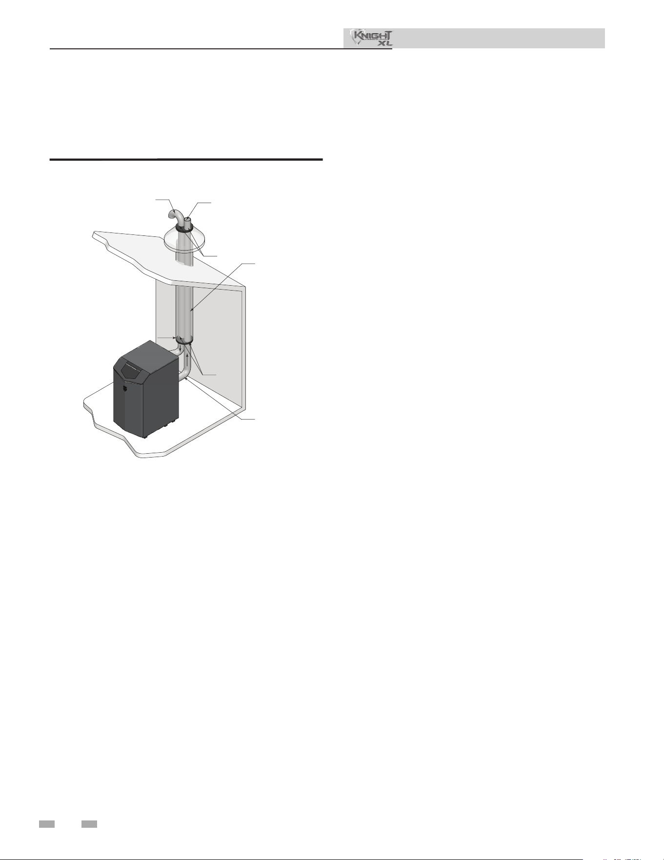
38
5 Vertical direct venting (continued)
Existing vent as a chase
Follow all existing termination and clearance requirements and
allowable pipe lengths. Use only approved venting materials
listed in the General Venting Section of this manual.
Figure 5-10 Existing Vent as a Chase
DIR #2000585169 00
FLUE EXHAUST
AIRINLET
EXISTING
SEAL
CAP
SEAL
FLUE OUTLET
*For concept illustration only. Individual installations
may vary due to job site specic equipment.
Installation & Operation Manual
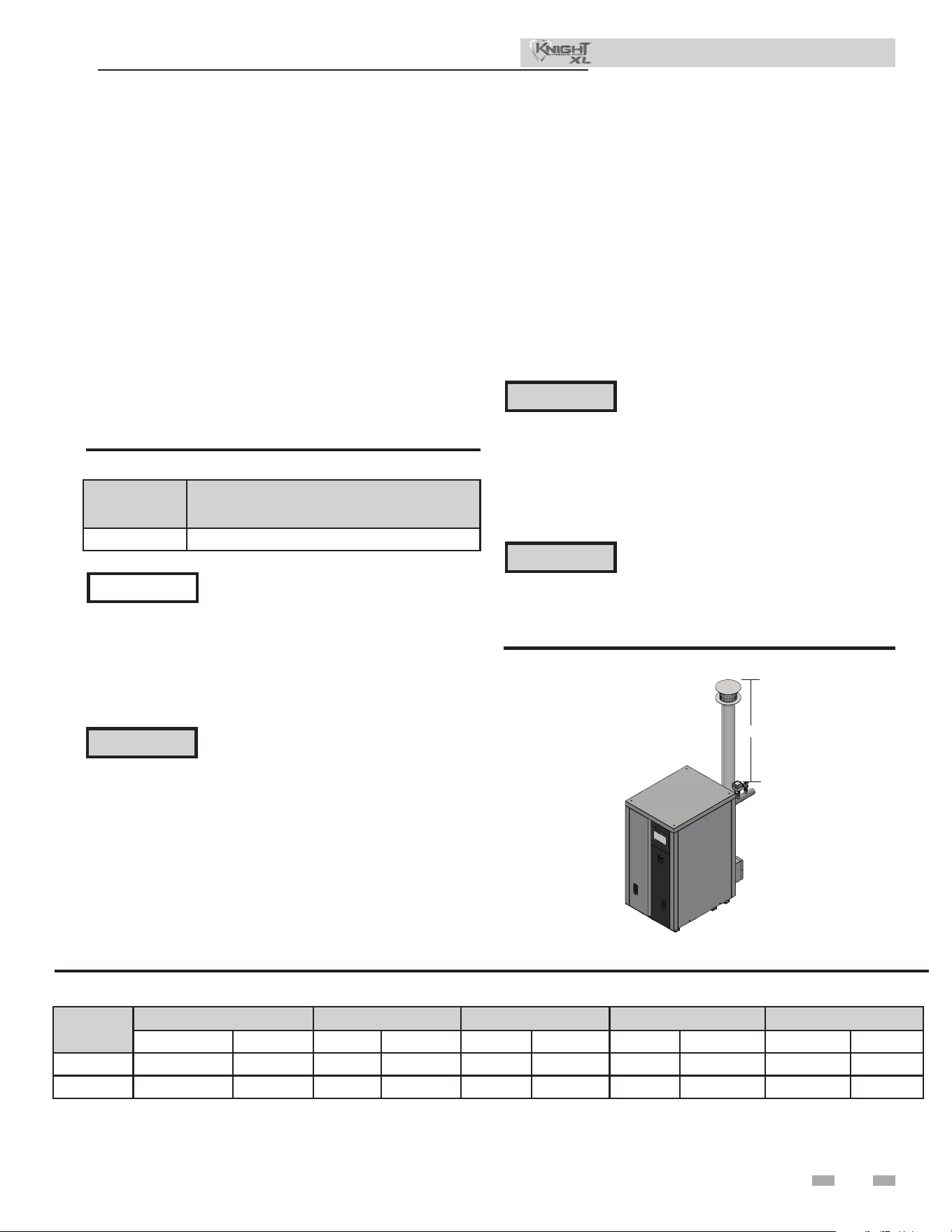
39
6 Outdoor installations
Installation & Operation Manual
Outdoor venting
• In order to properly install the appliance in an outdoor
conguration, the appropriate outdoor ready model (ex.
KBX0400N-O) must be purchased WITH a factory
supplied outdoor installation kit.
• In order to properly install the appliance in an outdoor
conguration the optional outdoor kit must be used (see
Table 6A).
• Vent materials for outdoor venting are to be eld supplied.
• Vent materials must be stainless steel.
• e vent must terminate at least 36 inches above the top of
the unit.
• All vent materials must be supported as recommended by
the vent manufacturer.
• e terminations in Table 6B must be used.
Model Indoor to Outdoor Conversion Kit
400 - 1000 100331712
Table 6A Indoor to Outdoor Conversion Kit
Before installing a venting system, follow all
requirements found in the General Venting
section of this manual.
Outdoor vent / air inlet location
Keep venting areas free of obstructions. Keep area clean and free
of combustible and ammable materials. Maintain minimum
clearances to combustibles as stated in this manual.
NOTICE
Only use the vent caps specied in this
manual. Personal injury or product damage
may result if any other cap is used, or if an
indoor model is used outdoors. Properly
install all covers, doors, and jacket panels
to ensure proper operation and prevent a
hazardous condition.
Units are self-venting and can be used outdoors when installed
with the optional outdoor kit. All vent materials must be eld
supplied and supported per the vent manufacturer’s instructions.
Combustion air supply must be free of contaminants (see the
Combustion and Ventilation Air Requirements section of this
manual). To prevent recirculation of the ue products into the
combustion air inlet, follow all instructions in this section.
⚠WARNING
Model
DuraVent Z-Flex Heat Fab Metal Fab Security Chimney
Adapter Rain Cap Adapter Rain Cap Adapter Rain Cap Adapter Rain Cap Adapter Rain Cap
400 - 500
FSA-4PVC-4FNS FSRC4 2SVSLA04 2SVSXITC04 9401PVC CCA04EX06 4CGPVCA 4FCSEC-C60 SS4PVCU SS4ECU
650 - 1000
810005231 FSRC6 - - 9601PVC CCA06EX08 6CGPVCA 6FCSEC-C60 SS6PVCU SS6ECU
Table 6B Approved Stainless Steel Adapters and Rain Caps
Location of unit
For outdoor models, you must install a ue termination.
Instructions for mounting the ue termination are included
in this manual. Do not install outdoor models directly on the
ground. You must install the outdoor unit on a concrete, brick,
block, or other non-combustible pad. See Outdoor Installation
Venting. A wind proof cabinet protects the unit from weather.
is product contains a condensate
management and disposal system that
may be subject to freezing if exposed
to sustained temperatures below 32°F.
Precautions should be taken to protect
the condensate trap and drain lines during
extended periods of outdoor temperatures
below 32°F.
⚠WARNING
CAUTION
is unit is not intended for installations
where temperatures may reach below 32°F
(0°C). Exposure to freezing temperatures
will cause the system and appliance to
freeze and leak.
DIR #2000586797 00
36"
Figure 6-1 Outdoor installation
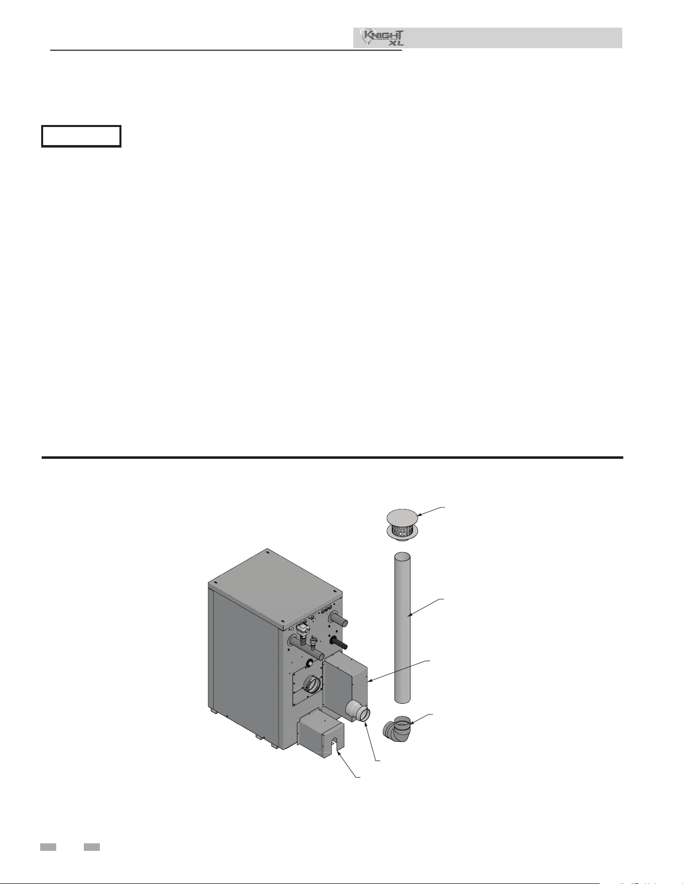
40
6 Outdoor installations (continued)
Installation & Operation Manual
Outdoor venting
NOTICE
Before installing a venting system, follow all requirements found in the General Venting section.
Units are self-venting and can be used outdoors when installed with the optional outdoor kit.
Combustion air supply must be free of contaminants (see Combustion and Ventilation Air, page 10). To prevent recirculation of
the ue products into the combustion air inlet, follow all instructions in this section.
Outdoor vent/air inlet location
Keep venting areas free of obstructions. Keep area clean and free of combustible and ammable materials. Maintain a minimum
clearance of 3" (76 mm) to combustible surfaces and a minimum of 36" (915 mm) clearance to the air inlet. To avoid a blocked air
inlet or blocked ue condition, keep the air inlet, ue outlet, and condensate trap clear of leaves, debris, etc.
Do not install outdoor models directly on the ground. You must install the outdoor unit on a concrete, brick, block, or other non-
combustible pad.
Do not locate unit so that high winds can deect o of adjacent walls, buildings, or shrubbery causing recirculation. Recirculation
of ue products may cause operational problems, bad combustion, or damage to controls.
Multiple unit outdoor installations require 48" (1.22 m) clearance between each vent cap. Locate outdoor cap at least 48" (1.22m)
below and 48" (1.22 m) horizontally from any window, door, walkway, or gravity air intake.
Locate unit at least 10 feet (3.05 m) away from any forced air inlet.
Locate unit at least 3 feet (0.91 m) outside any overhang.
Clearances around outdoor installations can change with time. Do not allow the growth of trees, shrubs, or other plants to obstruct
the proper operation of the outdoor vent system.
Do not install in locations where rain from building runo drains will spill onto the unit.
90° STAINLESS STEEL
ELBOW (FIELD SUPPLIED
AS NEEDED)
STAINLESS STEEL
VENT PIPE
(FIELD SUPPLIED)
RAIN CAP
(FIELD SUPPLIED)
DIR #2000586797 00
CONDENSATE TRAP COVER
RAIN CHANNEL COVER
VENT ADAPTER (FIELD SUPPLIED)
Figure 6-2 Outdoor Venting - Stainless Steel
NOTE: See Table 6B for approved stainless steel adapters and rain caps.
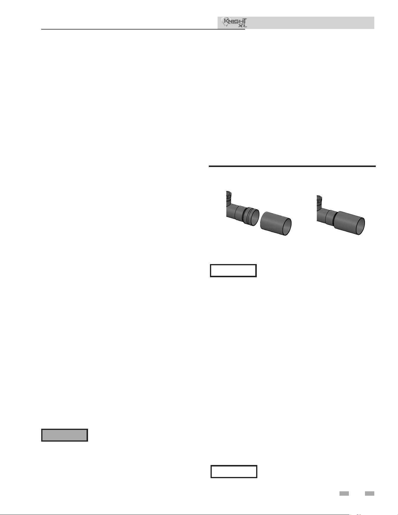
41
7 Hydronic piping
System water piping methods
e Knight XL is designed to function in a closed loop
pressurized system not less than 12 psi (83 kPa) (Non-
metallic system piping must have an oxygen barrier to be
considered a closed loop). A temperature and pressure
gauge is included to monitor system pressure and outlet
temperature and should be located on the boiler outlet.
It is important to note that the boiler has a minimal amount
of pressure drop which must be gured in when sizing
the circulators. Each boiler installation must have an air
elimination device, which will remove air from the system.
Install the boiler so the gas ignition system components
are protected from water (dripping, spraying, etc.) during
appliance operation or basic service of circulator replacement,
valves, and others.
Observe a minimum of 1/4 inch (6 mm) clearance around all
un-insulated hot water pipes when openings around the pipes
are not protected by non-combustible materials.
Low water cutoff device
On a boiler installed above radiation level, some states and
local codes require a low water cuto device at the time of
installation.
Chilled water system
If the boiler supplies hot water to heating coils in air handler
units, ow control valves or other devices must be installed to
prevent gravity circulation of heater water in the coils during
the cooling cycle. A chilled water medium must be piped in
parallel with the heater.
Freeze protection uids
Freeze protection for new or existing systems must use
glycol that is specially formulated for this purpose. is
includes inhibitors, which prevent the glycol from attacking
the metallic system components. Make certain to check that
the system uid is correct for the glycol concentration and
inhibitor level. e system should be tested at least once
a year and as recommended by the producer of the glycol
solution. Allowance should be made for the expansion of the
glycol solution in the system piping.
General piping information
Basic steps are listed below along with illustrations on the
following pages (FIG.’s 6-7 through 6-11), which will guide you
through the installation of the Knight XL (reference FIG.’s 7-2A
and 7-2B).
1. Connect the system return marked “Inlet”.
2. Connect the system supply marked “Outlet”.
3. Install purge and balance valve or shuto valve and drain on
system return to purge air out of each zone.
4. Install a backow preventer on the cold feed make-up water
line.
5. Install a pressure reducing valve on the cold feed make-up
water line, (15 psi (103 kPa) nominal). Check temperature
and pressure gauge (shipped separately), which should read
a minimum pressure of 12 psi (83 kPa).
6. Install a circulator as shown on the piping diagrams in this
section. Make sure the circulator is properly sized for the
system and friction loss.
Use only inhibited propylene glycol
solutions, which are specically formulated
for hydronic systems. Ethylene glycol is
toxic and can attack gaskets and seals used
in hydronic systems.
⚠ WARNING
e relief valve, tee and any other necessary
ttings are shipped in the install kit with the
boiler and are to be eld installed (FIG. 7-1).
Installation & Operation Manual
NOTICE
IMPORTANT
All boiler piping must contain an oxygen
barrier. is will help prevent any excess
oxygen from entering the system.
Water connections
e inlet and outlet water connections on the KBX0400 -
KBX0800 are 2” copper sweat. e inlet and outlet water
connections on the KBX1000 are 2-1/2” copper sweat. e
KBX1000 water connections also have a groove in case a groove-
lock tting is preferred. For copper-to-copper connections,
Victaulic style 607 QuikVic rigid couplings are recommended.
For copper-to-stainless steel connections, Victaulic style 644
transition couplings are recommended. For copper-to-carbon
steel connections, Victaulic style 647 dielectric transitions are
recommended. For other groove-lock connection styles contact
the factory.
Figure 7-1A Sweat connection for 1000
2000612893 00
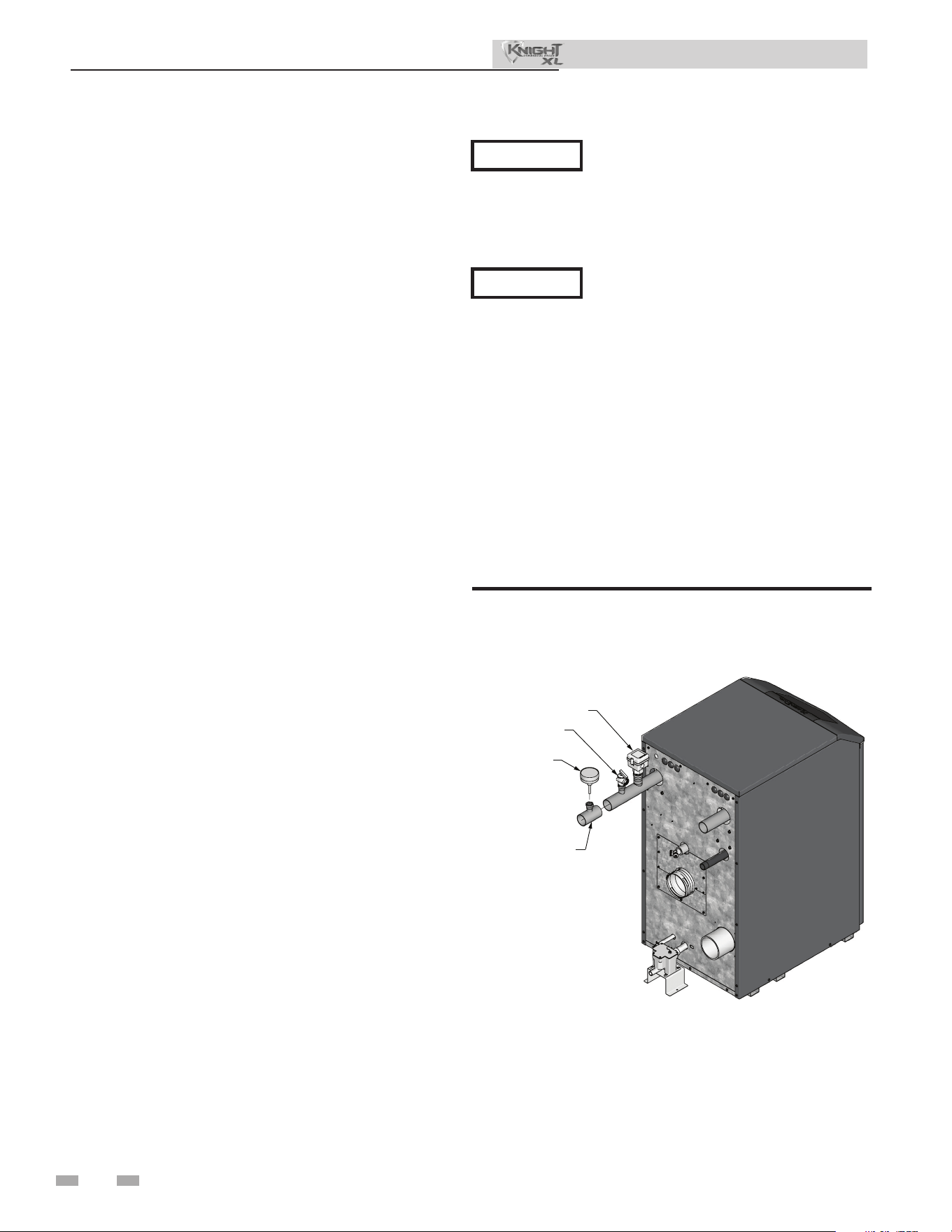
42
Temperature and pressure gauge
installation
Basic steps are listed below to guide you through the
installation of the temperature and pressure gauge provided
with the unit.
1. Install a eld provided tee with the gauge tting
positioned vertically and on the top (FIG. 7-1B)
2. Install the temperature and pressure gauge provided
with the unit into the top tting of the tee (a bushing
may be necessary) installed in Step 8 (FIG. 7-1B).
DIR #2000585175 00
RELIEF VALVE
FLOW SWITCH
TEMPERATURE &
PRESSURE GAUGE
TEE WITH FITTING ON TOP
(FIELD PROVIDED)
Figure 7-1B Temperature and Pressure Gauge Installation
7 Hydronic piping (continued)
See the piping illustrations included in this section, FIG.’s 7-4
thru 7-8 for suggested guidelines in piping the Knight XL.
Please note that these illustrations are
meant to show system piping concept
only, the installer is responsible for all
equipment and detailing required by local
codes.
NOTICE
Installation & Operation Manual
A magnetic separator is recommended
when a unit is installed in a retrot system
or a system containing steel and/or cast
iron pipe.
NOTICE
7. Install an expansion tank on the system supply. Consult the
tank manufacturer’s instruction for specic information
relating to tank installation. Size the expansion tank for
the required system volume and capacity.
8. Install an air elimination device on the system supply.
9. Install a drain valve at the lowest point of the system.
Note: e boiler cannot be drained completely of water
without purging the unit with an air pressure of 15 psi
(103 kPa).
10. is appliance is supplied with a relief valve sized in
accordance with ASME Boiler and Pressure Vessel Code,
Section IV (“Heating Boilers”). Pipe the discharge of the
safety relief valve to a suitable drain to prevent injury
in the event of pressure relief. Provide piping that is the
same size as the safety relief valve outlet. Never block the
outlet of the safety relief valve.
11. Install a eld supplied strainer/lter to prevent damage
to the heat exchanger caused by debris entering from the
system piping. When installing in a pre-existing system,
a strainer/lter capable of removing debris le in the
system is recommended.
12. Install a eld supplied magnetic separator in the heating
system return line as close as practical to the boiler per
the manufacturer’s instructions.

7 Hydronic piping
Near boiler piping components
1. Boiler system piping:
Boiler system piping MUST be sized per the pipe
requirements listed in Table 6B. Reducing the pipe size
can restrict the ow rate through the boiler, causing
inadvertent high limit shutdowns and poor system
performance. Flow rates are based on 20 feet (6 m) of
piping, 4 - 90° elbows, and 2 - fully ported ball valves.
2. Boiler system circulating pump:
Field supplied. e boiler circulating pump should be
based on the heat exchanger pressure drop and any
additional piping.
3. Domestic hot water circulating pump:
Field supplied. e pump MUST be sized to meet
the specied minimum ow requirements listed in FIG.
7-3. Consult the indirect water heater operating guide to
determine ow characteristics for the selected product
used.
4. Variable speed boiler system circulator:
Knight XL boilers are capable of controlling a variable
speed boiler system circulator. Variable speed circulators
MUST be sized to meet the specied minimum ow
requirements listed in FIG. 7-3 at full speed.
5. Boiler isolation valves:
Field supplied. Full port ball valves are required. Failure
to use full port ball valves could result in a restricted ow
rate through the boiler.
6. Check valves:
Field supplied. Check valves are recommended for
installation as shown in FIG.’s 6-7 through 6-11. Failure
to install check valves could result in a reverse ow
condition during pump(s) o cycle.
7. Domestic indirect hot water isolation valves:
Field supplied. Full port ball valves are required. Failure
to use full port ball valves could result in a restricted ow
rate through the boiler.
8. Anti-scald mixing valve:
Field supplied. An anti-scald mixing valve is
recommended when storing domestic hot water above
115°F (46°C).
9. Unions:
Field supplied. Recommended for unit serviceability.
10. Temperature and pressure gauge:
Factory supplied. e temperature and pressure gauge is
shipped loose. It is the responsibility of the contractor to
install the temperature and pressure gauge on the boiler
water outlet.
11. Pressure relief valve:
Factory supplied. e pressure relief valve is sized to
ASME specications.
12. Boiler purge valve:
Field supplied. e boiler purge valve is used to
remove entrapped air from the heat exchanger during
start-up.
13. System temperature sensor:
Lochinvar supplies a system temperature sensor. e
sensor is to be installed in the heating loop downstream
from the boiler hot water piping and heating loop
junction. e sensor should be located far enough
downstream to sense system diluted water temperature.
14. Water Meter:
Field supplied. A water meter to monitor makeup water is
recommended. Makeup water volume should not exceed
5% of total system per year.
15. Strainer/Filter:
Field supplied. Install a Y-strainer or equivalent multi-
purpose strainer/lter just before the boiler pump at
the inlet of the heat exchanger. is item is used to
remove system debris from older hydronic systems and
to protect newer systems.
16. Magnetic Separator:
Field supplied. Install a magnetic separator in the
heating system return line as close as practical to the
boiler per the manufacturer’s instructions.
43
Installation & Operation Manual
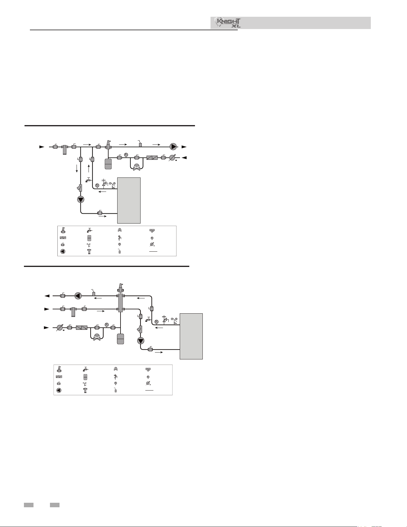
44
7 Hydronic piping (continued)
Near boiler piping connections
Figure 7-2A Near Boiler Piping w/Y-Strainer
Circulator sizing
e Knight XL heat exchanger does have a pressure drop,
which must be considered in your system design. Refer to the
graphs in FIG 7-3 pressure drop through the Knight XL heat
exchanger.
Figure 7-2B Near Boiler Piping w/Low Loss Header
Variable speed pump option
Variable speed pump setup
Before operation, ensure the following:
- Pump is set for an input signal of 0 - 10VDC by
the dip switches on the pump control
- Pump is set for external signal control (if
applicable)
- Pump is set for linear output (if applicable)
- If pump does not come equipped with a 0 - 10
VDC input option, an optional module will be
required from the vendor
Installation & Operation Manual
SMART TOUCH / Multi-temperature loop
control option
e Knight XL boiler is capable of producing up to
three (3) set point temperatures to meet dierent space
heating demands. When using more than one temperature
demand it is necessary to protect the lower temperature
loop from overheating. To help aid with this protection,
Lochinvar oers the Multi- Temperature Loop Control
Board Kit (100167843).
2000585376 01
TO
SYSTEM
FROM
SYSTEM
MAKE UP
WATER
BOILER
P
T P
LEGEND
AIR SEPARATOR
CIRCULATION
PUMP
FLOW SWITCH
PRESSURE GAUGE
P
TEMPERATURE &
PRESSURE GAUGE
T P
SYSTEM SUPPLY
SENSOR
BACKFLOW
PREVENTER
MAGNETIC SEPARATOR
WATER METER
STRAINER / FILTER
2 WAY VALVE
PRESSURE RELIEF
VALVE
BALL VALVE
EXPANSION TANK
PIPING
DRAIN PORT
2000808392 00
TO
SYSTEM
FROM
SYSTEM
BOILER
MAKE UP
WATER
P
T P
LOW LOSS
HEADER
LEGEND
AIR SEPARATOR
CIRCULATION
PUMP
FLOW SWITCH
PRESSURE GAUGE
P
TEMPERATURE &
PRESSURE GAUGE
T P
SYSTEM SUPPLY
SENSOR
BACKFLOW
PREVENTER
MAGNETIC SEPARATOR
WATER METER
STRAINER / FILTER
2 WAY VALVE
PRESSURE RELIEF
VALVE
BALL VALVE
EXPANSION TANK
PIPING
DRAIN PORT
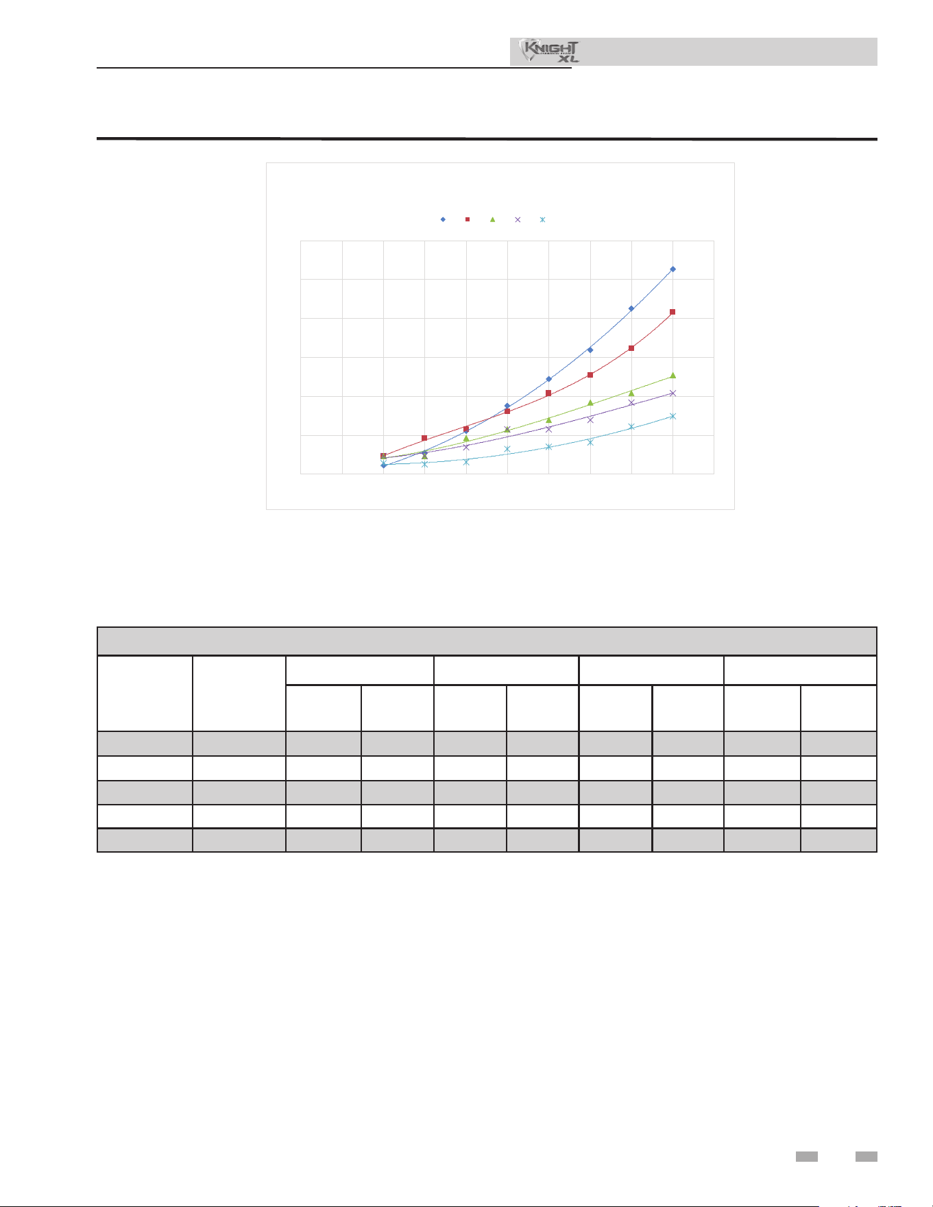
45
Figure 7-3 Pressure Drop vs. Flow
Table 7A Sizing Information for Temperature Rise Applications_20°F, 25°F, 30°F and 35°F
0
10
20
30
40
50
60
010203040506070809
01
00
PRESSURE DROP (FT. HD)
FLOW RATE (GPM)
PRESSURE DROP VS FLOW
(HEAT EXCHANGER ONLY)
400 500 650 800 1000
TEMPERATURE RISE APPLICATIONS
Model
MINIMUM
PIPE
SIZE
20°F 25°F 30°F 35°F
GPM FT/HD GPM FT/HD GPM FT/HD GPM FT/HD
400
2" 38 10 30 7 25 5 22 4
500
2" 48 14 38 12 32 9 27 8
650
2" 62 16 50 11 41 9 36 7
800
2" 76 17 61 13 51 10 44 9
1000
2 1/2" 96 18 76 11 64 8 54 6
7 Hydronic piping
Installation & Operation Manual
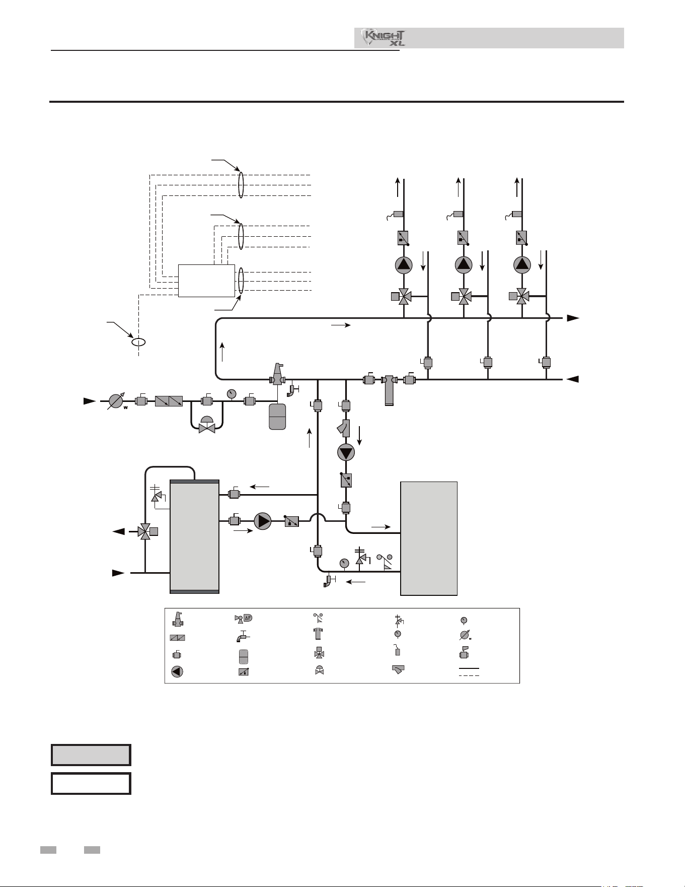
46
7 Hydronic piping (continued)
Figure 7-4 Single Boiler - Multiple Temperatures
Please note that these illustrations are meant to show system piping concept only, the installer is responsible
for all equipment. e installer must follow all manufacturer’s instructions for each system component. e
installer is responsible for compliance with local codes.
NOTICE
CAUTION
Mixing valves are required for the protection of low temperature loops.
Installation & Operation Manual
2000808393 00
INDIRECT
DHW
TANK
BOILER
COLD
WATER IN
DWH HOT
WATER OUT
T P
MAKE UP
WATER
P
TO
SYSTEM
MULTI TEMP.
LOOP CNTL
(OPTIONAL)
FROM
SYSTEM
TEMP
LOOP 3
TEMP
LOOP 2
TEMP
LOOP 1
24VAC SIGNAL TO
MIXING VALVES
SHEILDED CABLE
TO BOILER
120VAC
TO PUMPS
WIRES TO
LOOP SENSORS
SENSOR 1
PUMP 1
VALVE 1
SENSOR 3
SENSOR 2
PUMP 3
PUMP 2
VALVE 3
VALVE 2
SENSOR 1 SENSOR 2 SENSOR 3
PUMP 1 PUMP 2
PUMP 3
VALVE 1 VALVE 2 VALVE 3
LEGEND
AIR SEPARATOR
CIRCULATION
PUMP
FLOW CHECK VALVE
PRESSURE GAUGE
P
TEMPERATURE &
PRESSURE GAUGE
T P
SYSTEM SUPPLY
SENSOR
BACKFLOW
PREVENTER
MAGNETIC SEPARATOR
WATER METER
STRAINER / FILTER
2 WAY VALVE
PRESSURE RELIEF
VALVE
BALL VALVE
EXPANSION TANK
PIPING
DRAIN PORT
DIFFERENTIAL
PRESSURE
BYPASS VALVE
2 WAY MOTORIZED
VALVE (OPTIONAL)
MIXING VALVE
ANTI SCALD
FLOW SWITCH
WIRING
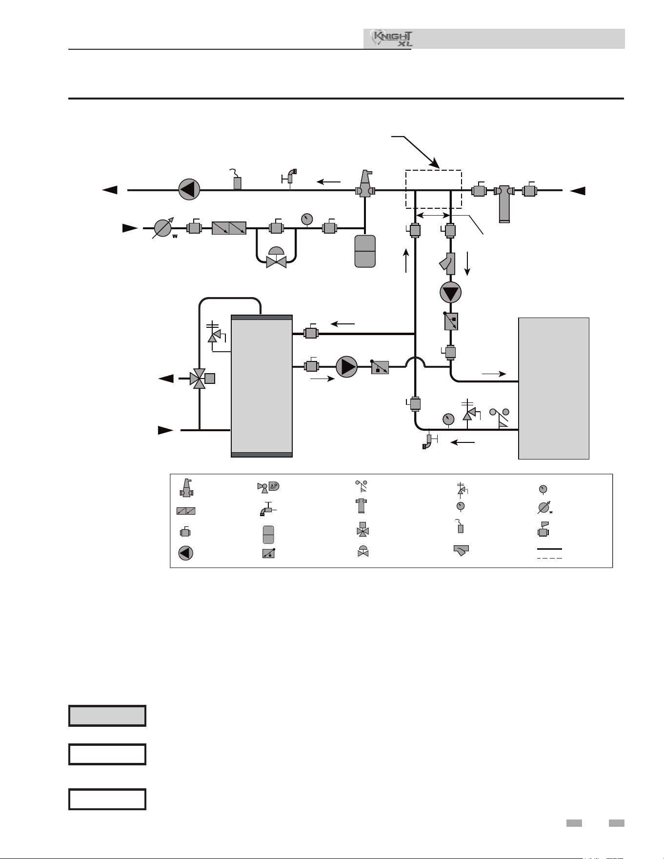
47
7 Hydronic piping
Figure 7-5 Single Boiler - Primary/Secondary Piping
NOTICE
System ow should always remain higher than the required ow for the boiler(s) when the boiler(s) is in
operation to prevent short cycling and high limit issues.
Please note that these illustrations are meant to show system piping concept only, the installer is responsible
for all equipment. e installer must follow all manufacturer’s instructions for each system component. e
installer is responsible for compliance with local codes.
NOTICE
CAUTION
Indirect water heaters are capable of transferring a limited number of Btu’s into the water. Ensure boiler
output does not not exceed indirect water heater transfer capabilities.
Installation & Operation Manual
2000808394 00
INDIRECT
DHW
TANK
BOILER
T P
MAKE UP
WATER
P
TO
SYSTEM
FROM
SYSTEM
MAY SUBTITUTE
LOW LOSS HEADER
NOT TO EXCEED 4 PIPE DIA OR
MAX OF 12” APART
COLD
WATER IN
DWH HOT
WATER OUT
LEGEND
AIR SEPARATOR
CIRCULATION
PUMP
FLOW CHECK VALVE
PRESSURE GAUGE
P
TEMPERATURE &
PRESSURE GAUGE
T P
SYSTEM SUPPLY
SENSOR
BACKFLOW
PREVENTER
MAGNETIC SEPARATOR
WATER METER
STRAINER / FILTER
2 WAY VALVE
PRESSURE RELIEF
VALVE
BALL VALVE
EXPANSION TANK
PIPING
DRAIN PORT
DIFFERENTIAL
PRESSURE
BYPASS VALVE
2 WAY MOTORIZED
VALVE (OPTIONAL)
MIXING VALVE
ANTI SCALD
FLOW SWITCH
WIRING
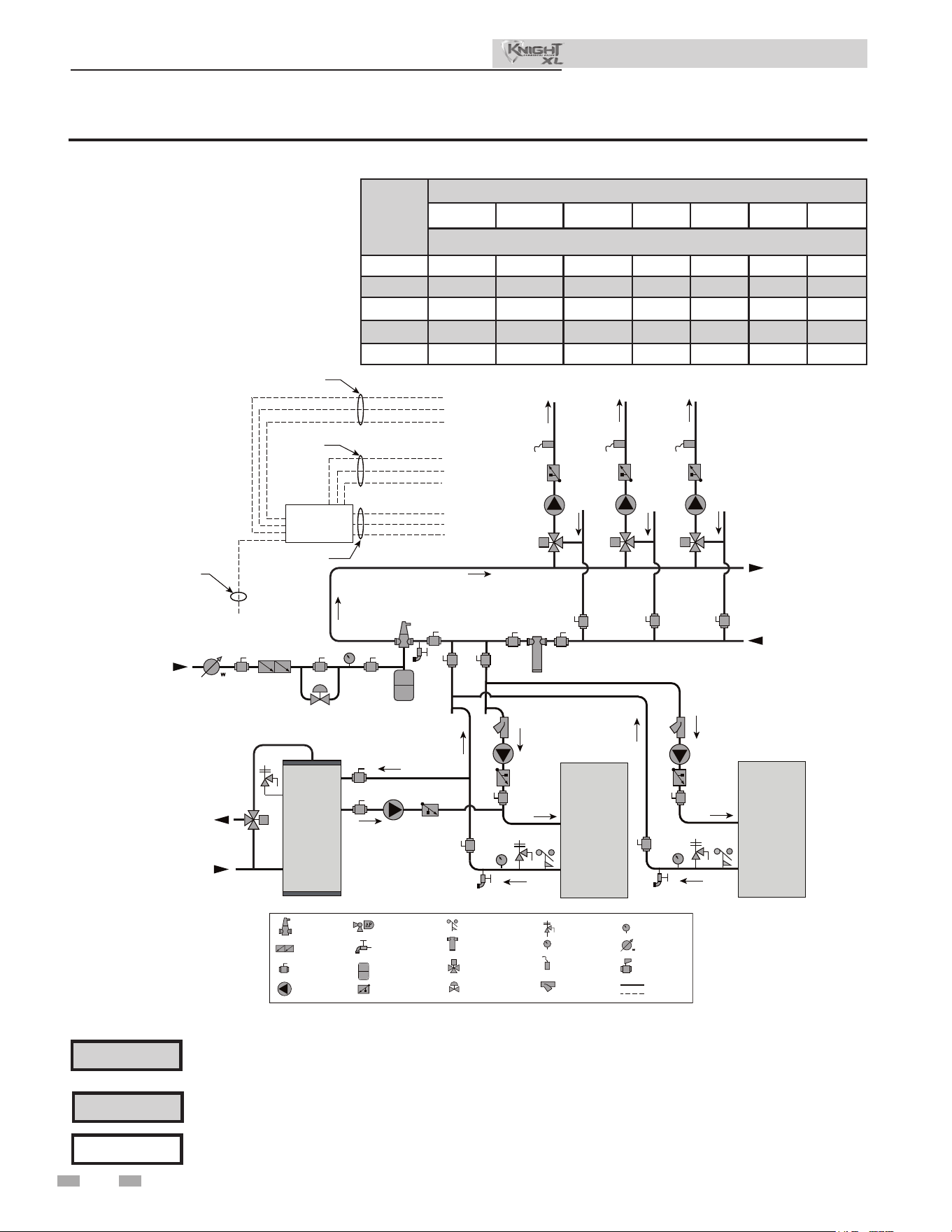
48
7 Hydronic piping (continued)
Figure 7-6 Multiple Boilers - Multiple Temperatures
Please note that these illustrations are meant to show system piping concept only, the installer is responsible
for all equipment. e installer must follow all manufacturer’s instructions for each system component. e
installer is responsible for compliance with local codes.
NOTICE
CAUTION
Mixing valves are required for the protection of low temperature loops.
CAUTION
Indirect water heaters are capable of transferring a limited number of Btu’s into the water. Ensure boiler
output does not not exceed indirect water heater transfer capabilities.
Model
Number of Units
2 3 4 5 6 7 8
Required Pipe Sizes in NPT (Based on 30°△)
400
2.5 3 4 4 6 6 6
500
3 4 4 4 6 6 6
650
3 4 4 6 6 6 6
800
4 4 6 6 6 6 8
1000
4 6 6 6 8 8 8
Installation & Operation Manual
2000808395 00
INDIRECT
DHW
TANK
BOILER 1
T P
MAKE UP
WATER
P
TO
SYSTEM
MULTI TEMP.
LOOP CNTL
(OPTIONAL)
FROM
SYSTEM
TEMP
LOOP 3
TEMP
LOOP 2
TEMP
LOOP 1
24VAC SIGNAL TO
MIXING VALVES
SHEILDED CABLE
TO BOILER
120VAC
TO PUMPS
WIRES TO
LOOP SENSORS
SENSOR 1
PUMP 1
VALVE 1
SENSOR 3
SENSOR 2
PUMP 3
PUMP 2
VALVE 3
VALVE 2
SENSOR 1 SENSOR 2 SENSOR 3
PUMP 1 PUMP 2
PUMP 3
VALVE 1 VALVE 2 VALVE 3
BOILER 2
T P
COLD
WATER IN
DWH HOT
WATER OUT
LEGEND
AIR SEPARATOR
CIRCULATION
PUMP
FLOW CHECK VALVE
PRESSURE GAUGE
P
TEMPERATURE &
PRESSURE GAUGE
T P
SYSTEM SUPPLY
SENSOR
BACKFLOW
PREVENTER
MAGNETIC SEPARATOR
WATER METER
STRAINER / FILTER
2 WAY VALVE
PRESSURE RELIEF
VALVE
BALL VALVE
EXPANSION TANK
PIPING
DRAIN PORT
DIFFERENTIAL
PRESSURE
BYPASS VALVE
2 WAY MOTORIZED
VALVE (OPTIONAL)
MIXING VALVE
ANTI SCALD
FLOW SWITCH
WIRING
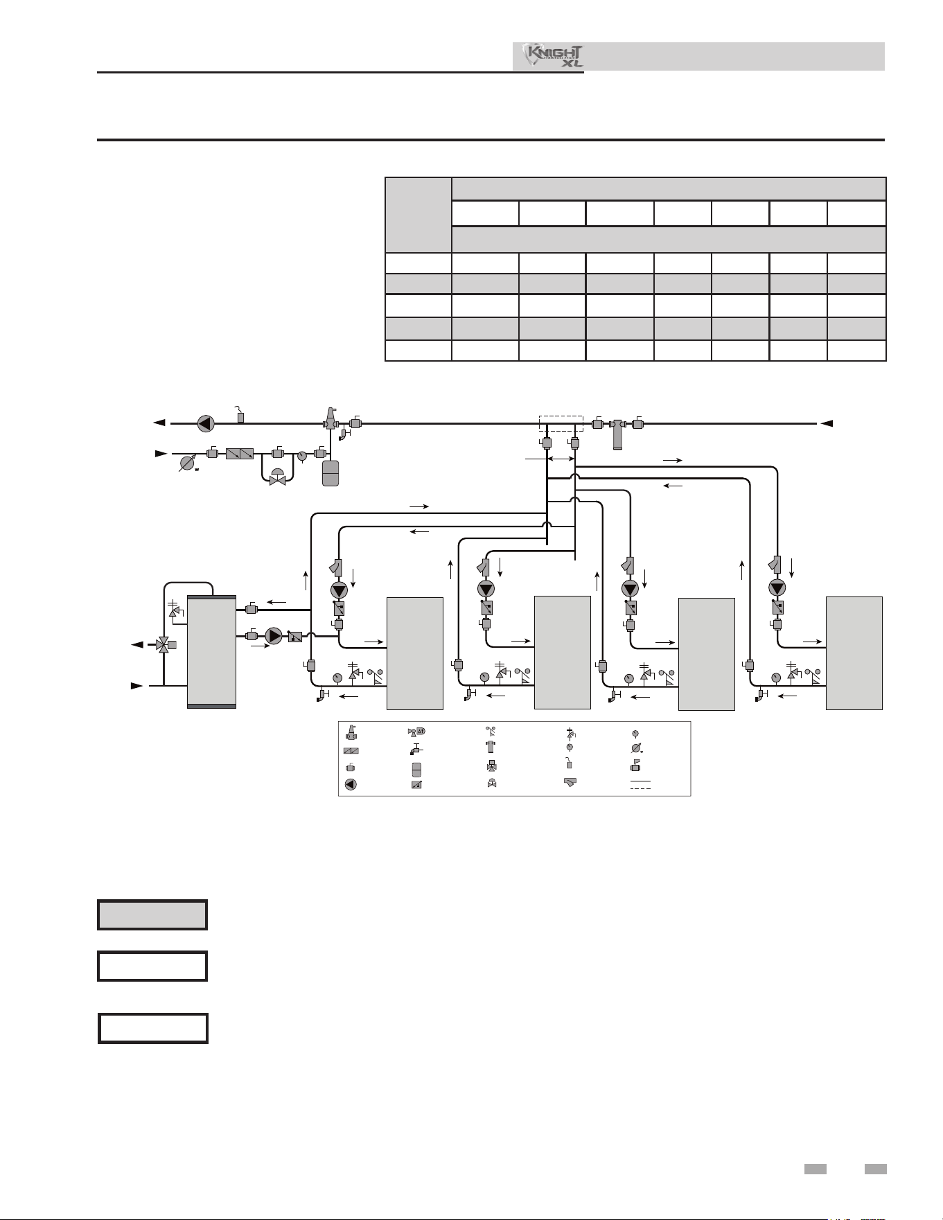
49
7 Hydronic piping
Figure 7-7 Multiple Boilers - Primary/Secondary Piping
NOTICE
System ow should always remain higher than the required ow for the boiler(s) when the boiler(s) is in
operation to prevent short cycling and high limit issues.
Please note that these illustrations are meant to show system piping concept only, the installer is responsible
for all equipment. e installer must follow all manufacturer’s instructions for each system component. e
installer is responsible for compliance with local codes.
NOTICE
CAUTION
Indirect water heaters are capable of transferring a limited number of Btu’s into the water. Ensure boiler
output does not not exceed indirect water heater transfer capabilities.
Installation & Operation Manual
Model
Number of Units
2 3 4 5 6 7 8
Required Pipe Sizes in NPT (Based on 30°△)
400
2.5 3 4 4 6 6 6
500
3 4 4 4 6 6 6
650
3 4 4 6 6 6 6
800
4 4 6 6 6 6 8
1000
4 6 6 6 8 8 8
2000808396 00
INDIRECT
DHW
TANK
BOILER 1
T P
MAKE UP
WATER
P
TO
SYSTEM
FROM
SYSTEM
BOILER 2
T P
BOILER 3
T P
BOILER 4
T P
MAY SUBTITUTE
LOW LOSS HEADER
NOT TO EXCEED 4 PIPE DIA OR
MAX OF 12” APART
COLD
WATER IN
DWH HOT
WATER OUT
LEGEND
AIR SEPARATOR
CIRCULATION
PUMP
FLOW CHECK VALVE
PRESSURE GAUGE
P
TEMPERATURE &
PRESSURE GAUGE
T P
SYSTEM SUPPLY
SENSOR
BACKFLOW
PREVENTER
MAGNETIC SEPARATOR
WATER METER
STRAINER / FILTER
2 WAY VALVE
PRESSURE RELIEF
VALVE
BALL VALVE
EXPANSION TANK
PIPING
DRAIN PORT
DIFFERENTIAL
PRESSURE
BYPASS VALVE
2 WAY MOTORIZED
VALVE (OPTIONAL)
MIXING VALVE
ANTI SCALD
FLOW SWITCH
WIRING
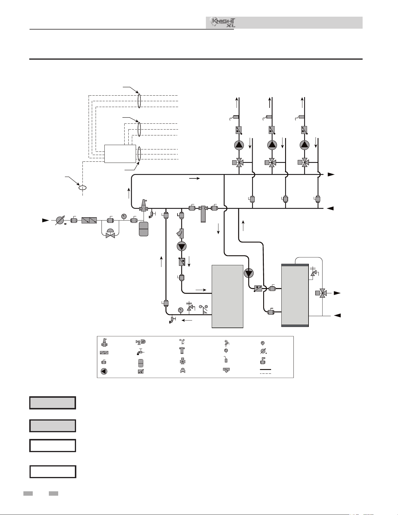
50
7 Hydronic piping (continued)
Figure 7-8 Single Boiler - Multiple Temperatures with DHW Piped as a Zone
Please note that these illustrations are meant to show system piping concept only, the installer is responsible
for all equipment. e installer must follow all manufacturer’s instructions for each system component. e
installer is responsible for compliance with local codes.
NOTICE
Please note that the installer is responsible for ensuring DHW prioritization when piped as a zone.
NOTICE
CAUTION
Mixing valves are required for the protection of low temperature loops.
CAUTION
Indirect water heaters are capable of transferring a limited number of Btu’s into the water. Ensure boiler
output does not not exceed indirect water heater transfer capabilities.
Installation & Operation Manual
2000808397 00
INDIRECT
DHW
TANK
BOILER
COLD
WATER IN
T P
MAKE UP
WATER
P
TO
SYSTEM
MULTI TEMP.
LOOP CNTL
(OPTIONAL)
FROM
SYSTEM
TEMP
LOOP 3
TEMP
LOOP 2
TEMP
LOOP 1
24VAC SIGNAL TO
MIXING VALVES
SHEILDED CABLE
TO BOILER
120VAC
TO PUMPS
WIRES TO
LOOP SENSORS
SENSOR 1
PUMP 1
VALVE 1
SENSOR 3
SENSOR 2
PUMP 3
PUMP 2
VALVE 3
VALVE 2
SENSOR 1 SENSOR 2 SENSOR 3
PUMP 1 PUMP 2
PUMP 3
VALVE 1 VALVE 2 VALVE 3
DWH HOT
WATER OUT
LEGEND
AIR SEPARATOR
CIRCULATION
PUMP
FLOW CHECK VALVE
PRESSURE GAUGE
P
TEMPERATURE &
PRESSURE GAUGE
T P
SYSTEM SUPPLY
SENSOR
BACKFLOW
PREVENTER
MAGNETIC SEPARATOR
WATER METER
STRAINER / FILTER
2 WAY VALVE
PRESSURE RELIEF
VALVE
BALL VALVE
EXPANSION TANK
PIPING
DRAIN PORT
DIFFERENTIAL
PRESSURE
BYPASS VALVE
2 WAY MOTORIZED
VALVE (OPTIONAL)
MIXING VALVE
ANTI SCALD
FLOW SWITCH
WIRING
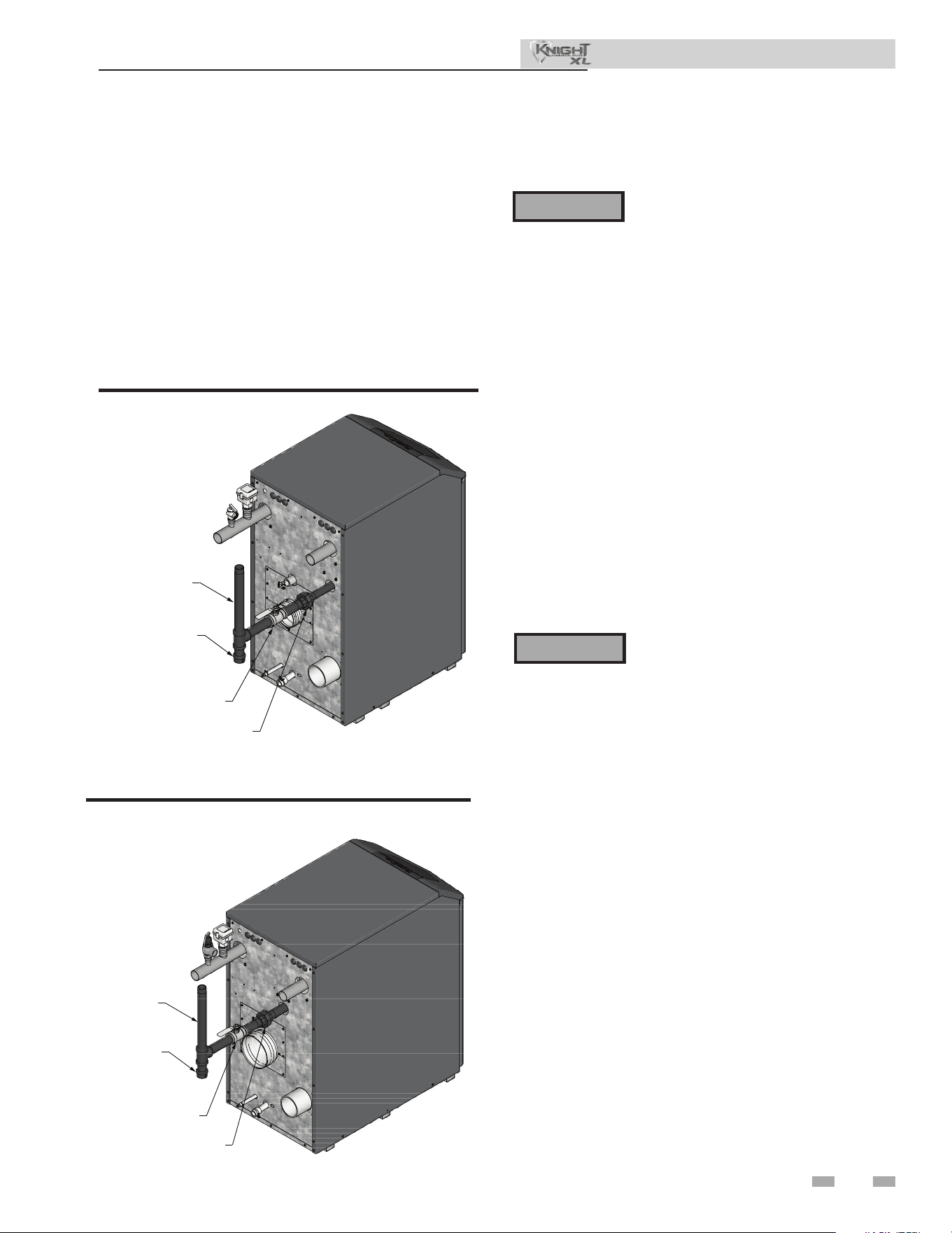
51
8 Gas connections
Connecting gas supply piping
1. Remove the top access panel and refer to FIG.’s 8-1 thru
8-2 to pipe gas to the boiler.
a. Install ground joint union for servicing, when
required.
b. Install a manual shuto valve in the gas supply
piping outside boiler jacket when required by local
codes or utility requirements.
c. In Canada – When using manual main shuto
valves, it must be identied by the installer.
2. Install sediment trap / drip leg.
Figure 8-1 Gas Supply Piping - Models 400 - 500
3. Support piping with hangers, not by the boiler or its
accessories.
Do not check for gas leaks with an open
ame – use the bubble test. Failure to use
the bubble test or check for gas leaks can
cause severe personal injury, death, or
substantial property damage.
Figure 8-2 Gas Supply Piping - Models 650 - 1000
4. Purge all air from the gas supply piping.
5. Before placing the boiler in operation, check the boiler
and its gas connection for leaks.
a. e appliance must be disconnected from the gas
supply piping system during any pressure testing of
that system at a test pressure in excess of 1/2 PSIG
(3.5 kPa).
b. e appliance must be isolated from the gas supply
piping system by closing a manual shuto valve
during any pressure testing of the gas supply piping
system at test pressures equal to or less than 1/2 PSIG
(3.5 kPa).
c. e appliance and its gas connection must be leak
tested before placing it in operation.
e gas valve and blower will not support
the weight of the piping. Do not attempt
to support the weight of the piping with
the boiler or its accessories. Failure to
comply could result in severe personal
injury, death, or substantial property
damage.
⚠ WARNING
⚠ WARNING
6. Use pipe sealing compound compatible with propane
gases. Apply sparingly only to male threads of the pipe
joints so that pipe dope does not block gas ow.
DIR #2000585192 00
UNION
(FIELD PROVIDED)
SEDIMENT TRAP /
DRIP LEG
GAS SUPPLY
MANUAL SHUTOFF VALVE
(FACTORY SUPPLIED)
DIR #2000585192 00
UNION
(FIELD PROVIDED)
SEDIMENT
TRAP /
DRIP LEG
GAS SUPPLY
MANUAL
SHUTOFF VALVE
(FACTORY SUPPLIED)
Installation & Operation Manual
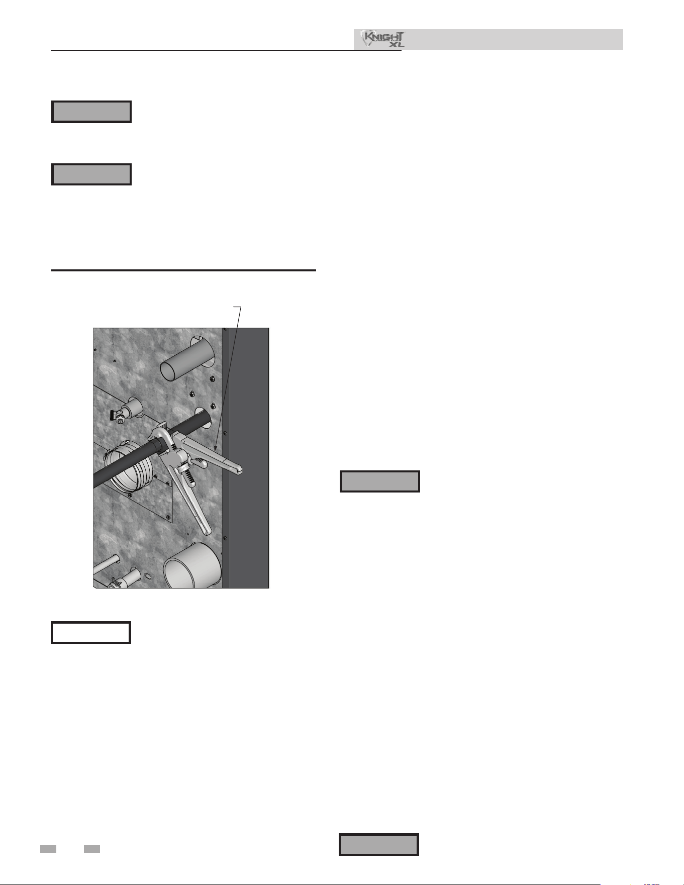
52
8 Gas connections (continued)
Failure to apply pipe sealing compound
as detailed in this manual can result
in severe personal injury, death, or
substantial property damage.
Use two wrenches when tightening gas
piping at boiler (FIG. 8-3), using one
wrench to prevent the boiler gas line
connection from turning. Failure to
support the boiler gas connection pipe
to prevent it from turning could damage
gas line components.
DIR #2000588342 00
USEBACK-UP WRENCH TO
PREVENT PIPE FROM ROTATING
Figure 8-3 Inlet Pipe with Back-up Wrench
Natural gas:
Pipe sizing for natural gas
1. Refer to Table 8A for pipe length and diameter. Based on
rated boiler input (divide by 1,000 to obtain cubic feet per
hour).
a. Table 8A is only for natural gas with specic gravity
0.60 inches, with a pressure drop through the gas
piping of 0.3 inches w.c.
b. For additional gas pipe sizing information, refer to
ANSI Z223.1 (or B149.1 for Canadian installations).
Natural gas supply pressure requirements
1. Pressure required at the gas valve inlet pressure port:
• Maximum 12 inches w.c. (3.5 kPa) with no ow
(lockup) or with boiler on.
• Minimum 4 inches w.c. (.99 kPa) with gas owing (verify
during boiler startup).
2. Install 100% lockup gas pressure regulator in supply line
if inlet pressure can exceed 14 inches w.c. (3.5 kPa) at any
time. Adjust lockup regulator for 14 inches w.c. (3.5 kPa)
maximum.
Propane Gas:
Pipe sizing for propane gas
1. Contact gas supplier to size pipes, tanks, and 100% lockup
gas pressure regulator.
Propane Supply Pressure Requirements
1. Adjust propane supply regulator provided by the gas
supplier for 14 inches w.c. (3.2 kPa) maximum pressure.
2. Pressure required at gas valve inlet pressure port:
• Maximum 14 inches w.c. (3.2 kPa) with no ow (lockup)
or with boiler on.
• Minimum 8 inches w.c. (1.9 kPa) with gas owing (verify
during boiler startup).
Maximum inlet gas pressure must not
exceed the value specied. Minimum
value listed is for the purposes of input
adjustment.
⚠ WARNING
⚠ WARNING
NOTICE
⚠ WARNING
Ensure that the high gas pressure regulator
is at least 10 feet (3 m) upstream of the
appliance.
Installation & Operation Manual
⚠ WARNING
Knight XL boilers are typically shipped
ready to re on natural gas. Check boiler
rating plate to determine which fuel the
boiler is set for. If set to natural gas, it may
be converted to LP by installing a LP venturi
and making a gas valve adjustment (see
pages 13 and 14). In order to operate on LP
gas, an orice MUST BE installed (for 500
models) or a gas valve adjustment MUST
BE made. Failure to comply could result in
severe personal injury, death, or substantial
property damage.
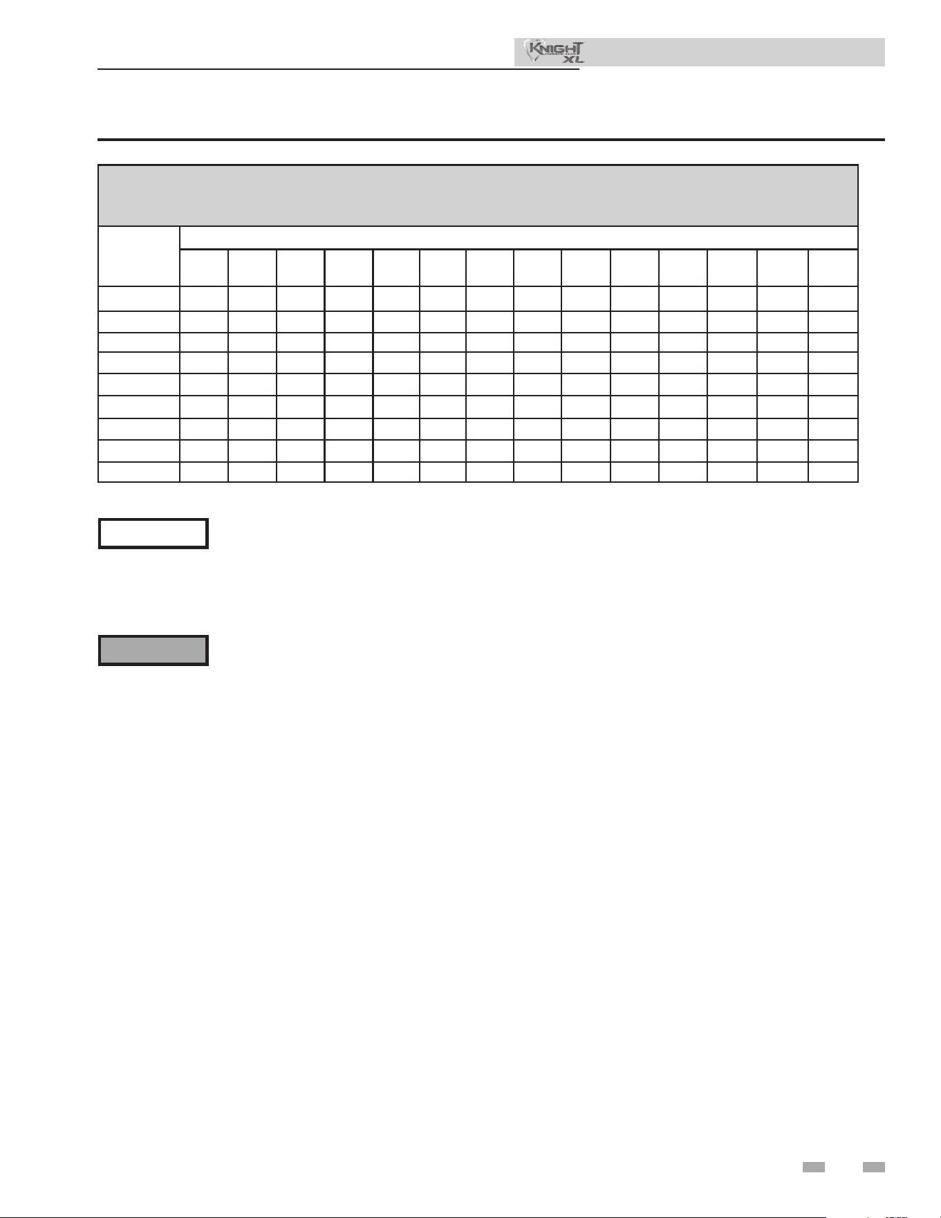
53
8 Gas connections
Table 8A Natural Gas Pipe Size Chart
e gas piping must be sized for the proper ow and length of
pipe, to avoid excessive pressure drop. Both the gas meter and
the gas regulator must be properly sized for the total gas load.
If you experience a pressure drop greater than 1 inch w.c.
(249 Pa), the meter, regulator, or gas line is undersized or in
need of service. Perform the steps below when checking inlet
gas supply:
1. Turn the main power switch to the “OFF” position.
2. Shut o gas supply at the manual gas valve in the gas
piping to the appliance.
3. On Models 400 - 500 loosen the set screw one (1) full turn
from inside the pressure tap on top of the gas valve. On
Models 650 - 1000 remove the 1/8" (3 mm) pipe plug on
the inlet ange to the valve and install a suitable 1/8" (3
mm) tting (eld supplied) for the manometer tubing.
Place the tubing of the manometer over the tap once the
set screw is loosened or the 1/8" (3 mm) tting is installed
(depending on model) as shown in FIG.’s 8-4 thru 8-5.
4. Slowly turn on the gas supply at the eld installed
manual gas valve.
5. Turn the power switch to the “ON” position.
6. Adjust the temperature set point on the display of the
SMART TOUCH control module to call for heat.
7. Observe the gas supply pressure as the burner res at
100% of rated input. Percent of burner input will be
displayed on the display.
8. Ensure inlet pressure is within specied range.
Minimum and maximum gas supply pressures are
specied in this section of the manual.
9. If gas supply pressure is within normal range and no
adjustments are needed, proceed on to Step 11.
10. If the gas pressure is out of range, contact the gas utility,
gas supplier, qualied installer or service agency to
determine the necessary steps to provide proper gas
pressure to the control.
11. Turn the power switch to the “OFF” position.
12. Shut o the gas supply at the manual gas valve in the gas
piping to the appliance.
13. Remove the manometer from the pressure tap on top of
the gas valve. On Models 400 - 500 re-tighten the set
screw inside the pressure tap. On Models 650 - 1000
remove the 1/8" (3 mm) eld supplied tting and
reinstall the pipe plug removed in Step 3.
Check inlet gas supply
NOTICE
CSA or UL listed exible gas connections
are acceptable, but you must exercise
caution to ensure that the line has adequate
capacity to allow your boiler to re at full
rate. Consult with local codes for proper
installation or service procedures.
DO NOT adjust gas valve outlet pressure.
Attempting to alter the gas valve outlet
pressure could result in damage to the valve,
causing potential severe personal injury,
death, or substantial property damage.
⚠ WARNING
Installation & Operation Manual
Capacity of Schedule 40 Metallic Pipe in Cubic Feet of Natural Gas Per Hour
(based on .60 specic gravity, 0.30" w.c. pressure drop)
Pipe
Size
(Inches)
Length of Pipe in Straight Feet
10 20 30 40 50 60 70 80 90 100 125 150 175 200
1/2 131 90 72 62 55 N/A N/A N/A N/A N/A N/A N/A N/A N/A
3/4 273 188 151 129 114 104 95 89 83 79 70 63 58 N/A
1 514 353 284 243 215 195 179 167 157 148 131 119 109 102
1 1/4 1,060 726 583 499 442 400 368 343 322 304 269 244 224 209
1 1/2 1,580 1,090 873 747 662 600 552 514 482 455 403 366 336 313
2 3,050 2,090 1,680 1,440 1,280 1,160 1,060 989 928 877 777 704 648 602
2 1/2 4,860 3,340 2,680 2,290 2,030 1,840 1,690 1,580 1,480 1,400 1,240 1,120 1,030 960
3 8,580 5,900 4,740 4,050 3,590 3,260 3,000 2,790 2,610 2,470 2,190 1,980 1,820 1,700
4 17,500 12,000 9,660 8,270 7,330 6,640 6,110 5,680 5,330 5,040 4,460 4,050 3,720 3,460
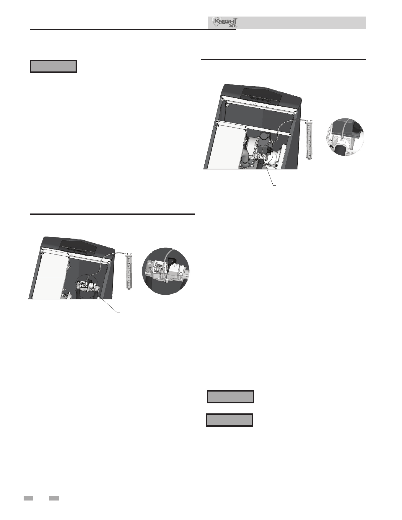
54
⚠ WARNING
When re-tightening the set screw, be sure
to tighten securely to prevent gas leaks.
Do not check for gas leaks with an open
ame -- use the bubble test. Failure to use
the bubble test or check for gas leaks can
cause severe personal injury, death, or
substantial property damage.
14. Turn on the gas supply at the manual gas valve.
15. Turn the power switch to the “ON” position.
16. Adjust the temperature set point on the display of
the SMART TOUCH control module to the desired
water temperature so the appliance will call for heat.
17. Check burner performance by cycling the system while
you observe burner response. e burner should ignite
promptly. Flame pattern should be stable. Turn system
o and allow burner to cool, then cycle burner again to
ensure proper ignition and ame characteristics.
Gas pressure
e gas pressure must remain between 4 inches w.c. (.99
kPa) minimum and 14 inches w.c. (3.5 kPa) maximum for
Natural gas and between 8 inches w.c. (1.9 kPa) minimum
and 14 inches w.c. (3.2 kPa) maximum for LP gas during
standby (static) mode and while in operating (dynamic)
mode. If an in-line regulator is used, it must be a minimum
of 10 feet (3 m) from the Knight XL boiler. It is very
important that the gas line is properly purged by the gas
supplier or utility company. Failure to properly purge the
lines or improper line sizing, will result in ignition failure.
e problem is especially noticeable in NEW LP installations
and also in empty tank situations. is can also occur when
a utility company shuts o service to an area to provide
maintenance to their lines.
Gas valve replacement
e gas valve MUST NOT be replaced with a conventional
gas valve under any circumstances. As an additional safety
feature, this gas valve has a anged connection to the venturi
and blower.
Figure 8-4 Inlet Gas Supply Check - Model 400 - 500
DIR #2000585203 00
LOOSEN THE SET SCREW ONE (1)
FULL TURN AND PLACE THE
MANOMETER TUBING OVER
THE PRESSURE TAP.
DETAIL
Figure 8-5 Inlet Gas Supply Check - Models 650 - 1000
DO NOT adjust gas valve outlet pressure.
Attempting to alter the gas valve outlet
pressure could result in damage to the
valve, causing potential severe personal
injury, death, or substantial property
damage.
Failure to follow all precautions could
result in re, explosion, or death!
⚠ WARNING
⚠ WARNING
DIR #2000585203 00
REMOVE THE 1/8" (3 MM) PIPE PLUG ON
THE INLET FLANGE TO THE VALVE AND
INSTALL A SUITABLE 1/8" (3 MM) FITTING
(FIELD SUPPLIED) FOR THE MANOMETER
TUBING.
DETAIL
8 Gas connections (continued)
Installation & Operation Manual
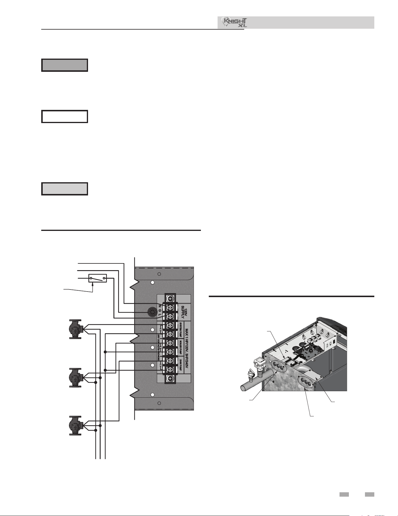
55
9 Field wiring
ELECTRICAL SHOCK HAZARD – For
your safety, turn o electrical power
supply before making any electrical
connections to avoid possible electric
shock hazard. Failure to do so can cause
severe personal injury or death.
Wiring must be N.E.C. Class 1.
If original wiring as supplied with boiler
must be replaced, use only type 105°C
wire or equivalent.
Boiler must be electrically grounded as
required by National Electrical Code
ANSI/NFPA 70 – latest edition.
Installation must comply with:
1. National Electrical Code and any other national, state,
provincial, or local codes, or regulations.
2. In Canada, CSA C22.1 Canadian Electrical Code Part 1,
and any local codes.
Line voltage connections
1. Connect 120 VAC power wiring to the line voltage terminal
strip in the junction box, as shown in FIG. 8-1.
2. Provide and install a fused disconnect or service switch
(15 amp recommended) as required by the code (see
FIG. 9-1).
3. When connecting a domestic hot water (DHW) pump,
connect the wiring to the line voltage terminal strip as
shown in FIG. 9-1.
4. To activate a system pump, wire as shown in FIG. 9-1. Dry
contacts are sized for 1 hp/120V, 3 hp/240V or 30 amps.
Figure 9-1 Line Voltage Field Wiring Connections
Label all wires prior to disconnection
when servicing controls. Wiring errors
can cause improper and dangerous
operation.
⚠ WARNING
NOTICE
⚠ CAUTION
Low voltage connections
1. Route all low voltage wires through the knockouts in the
rear of the boiler, as shown in FIG. 9-2.
2. Connect low voltage wiring to the low voltage connection
board as shown in FIG. 9-3 and the boiler wiring diagram.
DIR #2000585210 00
LOW VOLTAGE
CONNECTION BOARD
LOW VOLTAGE
WIRING KNOCKOUTS
LINE VOLTAGE
WIRING KNOCKOUTS
LINE VOLTAGE
JUNCTION BOX
Figure 9-2 Routing Field Wiring
Installation & Operation Manual
DOMESTIC
HO
T WATER
PUMP
BOILER
PUMP
SYSTEM
PUMP
120V SUPPLY
LINE
GROUND
NEUTRAL
W
G
BK
SERVICE
SWITCH
L2/N
G
L1
BK
G
W
BK
G
W
BK
G
W

56
9 Field wiring (continued)
Thermostat
1. Connect the room thermostats or end switches (isolated
contact only) to heat/loop demand 1, 2, or 3, as shown in
FIG. 9-3.
2. Install the thermostat on the inside wall away from
inuences of dras, hot or cold water pipes, lighting
xtures, television, sunlight, or replaces.
3. ermostat anticipator (if applicable):
a. If connected directly to boiler, set for 0.1 amps.
b. If connected to relays or other devices, set to match
total electrical power requirements of connected
devices. See device manufacturers’ specications
and thermostat instructions for details.
Outdoor temperature sensor
1. Mount the sensor on a north facing exterior wall, shielded
from direct sunlight or ow of heat or cooling from other
sources.
2. Route sensor wires through a knockout at the rear of the
boiler (see FIG. 9-2).
3. Connect the outdoor temperature sensor (FIG. 9-3) to
the outdoor sensor terminals on the connection board to
enable outdoor reset operation of the Knight XL. If xed
temperature operation is required, do not install outdoor
sensor.
DHW (Domestic Hot Water)
thermostat
Connect storage indirect water heater (DHW) thermostat
(FIG. 9-3) to the DHW thermostat terminals on the
connection board. If a tank sensor is connected (see DHW
Tank Sensor below) the tank thermostat is ignored.
DHW tank sensor
By installing a tank sensor, the SMART TOUCH control can
perform the tank thermostat function. e SMART TOUCH
control automatically detects the presence of this sensor, and
generates a DHW call for heat when the tank temperature
drops 6°F (3°C) below the tank set point, and nishes the call
for heat when the tank temperature reaches the tank set point.
e tank sensor included with the Lochinvar Squire® indirect
DHW tanks (100170544) is the only sensor suitable for use
with the SMART TOUCH control. Connect the sensor leads
to the Tank Sensor terminals on the low voltage connection
board (FIG. 9-3).
Louver proving switch
1. When the operation of the louvers needs to be veried
before the boiler res, remove the jumper wire from these
terminals and connect them to the normally open contacts
on its proving switch (FIG. 9-3).
High gas pressure switch
1. If a switch is provided to detect excessive gas pressure,
remove the jumper wire from the terminals on the
connection board, and then connect them to its normally
closed contacts (FIG. 9-3).
Low gas pressure switch
1. If a switch is provided to detect low gas pressure, remove
the jumper wire from the terminals on the connection
board and connect them to its normally open contacts
(FIG. 9-3).
2. If both a high and low gas pressure switch is used, connect
their respective contacts in series, and connect them to the
terminals on the connection board (FIG. 9-3).
Failure to use the correct sensor may
result in the tank temperature being either
above or below the set point.
⚠ WARNING
If 100170544 is not compatible with the indirect tank, a
tank thermostat can be used to control the boiler. e
tank thermostat should be installed per the manufacturer’s
instructions and wired to the DHW ermostat terminals on
the low voltage connection board (FIG. 9-3).
Variable speed system pump
If a variable speed pump is used in the primary loop, and a
0-10V signal is available from the pump speed control, this
signal can be used by the SMART TOUCH control to anticipate
changes in the building heat load. By connecting this 0 - 10V
signal to the 0 - 10V SYS PUMP IN terminals, the boiler (or
cascade) can modulate up and down as the primary ow
increases and decreases.
Boiler pump speed output
is 0 - 10V output is available to control the speed of a variable
speed boiler pump. e SMART TOUCH control will vary the
speed of this pump in order to maintain a minimum DT across
the heat exchanger, as well as prevent high limit lockouts when
the ow in the primary loop is extremely low. Connect this
output to the 0 - 10V input on the boiler pump speed control.
Rate output
is output provides a 0 - 10V signal that is proportional to the
ring rate of the boiler. is may be used by a BMS system to
monitor the actual rate of the boiler.
Installation & Operation Manual

57
9 Field wiring
Modbus / BACnet
When the optional ModBus / BACnet interface module is
installed, the RS-485 ModBus / BACnet cable is connected
to these terminals. Use shielded, 2-wire twisted pair cable. If
desired, the shield can be connected to ground by installing a
jumper wire between terminals 1 and 3 on connector X5 on the
optional ModBus / BACnet interface module.
System supply sensor
1. By installing the system supply sensor into the supply of
the primary loop, the temperature of the system supply can
be controlled. e SMART TOUCH control automatically
detects the presence of this sensor, and controls the boiler
ring rate to maintain the system supply temperature to the
set point (if the outlet sensor control is currently selected).
See the Knight XL Service Manual for instructions on how
to use the inlet sensor as the controlling sensor. When the
inlet sensor is programmed as the controlling sensor, it is
vital that the SYSTEM SUPPLY sensor be installed. DO
NOT INSTALL THE SYSTEM SUPPLY SENSOR INTO
THE SYSTEM RETURN.
2. e 100170581 sensor provided with the boiler must be
used for the system sensor.
3. Connect these terminals to the system supply sensor
(FIG. 9-3).
Alarm contacts
e SMART TOUCH control closes another set of contacts
whenever the boiler is locked out or the power is turned o.
is can be used to turn on an alarm, or signal a Building
Management System that the boiler is down.
Wiring of the cascade
When wiring the boilers for Cascade operation, select one
boiler as the Leader boiler. e remaining boilers will be
designated as Members. See “Conguration of the Cascade”
for a detailed explanation of this procedure.
Connect the system supply sensor and outdoor air sensor (if
used) to the Leader boiler. For the Cascade system to work
properly the system supply sensor must be installed. e
location of the system supply sensor should be downstream
of the boiler connections in the main system loop (FIG. 7-4
through 7-8). e system supply sensor should be wired to the
low voltage connection board at the terminals marked for the
system sensor (see FIG. 9-3). e Leader control will use the
water temperature at the system supply sensor to control the
operation of the Cascade.
If outdoor air reset is desired, the outdoor air sensor should
be wired to the low voltage connection board at the terminals
marked for the outdoor air sensor (FIG. 9-3). If the outdoor
air sensor is connected, the Leader control will calculate the
water temperature set point based on the programmed reset
curve parameters. If the outdoor air sensor is not connected,
the Leader control will maintain the xed water temperature
set point that is programmed into the control.
If a ermostat or Zone Control enable output is available,
it should be wired to the low voltage connection board on
the Leader boiler at the terminals marked for one of the
heat/loop demands 1-3 (FIG. 9-3). If the boilers are to run
continuously, connect a jumper wire between the R and W
terminals for the heat/loop demand input. is will initiate a
call for heat on the Cascade.
Communication between the Leader boiler and the Member
boilers is accomplished by using shielded, 2-wire twisted pair
communication cable. Connect one of the twisted pair wires
to Cascade terminal A on each of the low voltage connection
boards, and the other wire of the twisted pair to Cascade
terminal B on each of the low voltage connection boards.
Connect the shield wires to one of the shield terminals on
the low voltage connection boards (FIG. 9-3). If more than
two boilers are on the Cascade, daisy chain the wiring from
the Cascade terminals on the second boiler to the Cascade
terminals on the third boiler, then from the third to the forth,
and so on. e connections between boilers can be made in
any order, regardless of the addresses of the boilers. Try to
keep each cable as short as possible.
Boiler management system
1. An external control may be connected to control either
the ring rate or the set point of the boiler. If the
external control uses a set of contacts to enable the boiler,
connect the contacts to the heat/loop demand 1 terminals.
Otherwise, the SMART TOUCH control will be enabled by
the 0-10V signal.
2. Make sure the (-) terminal is connected to the (-) or
common output terminal of the external control, and the
(+) terminal is connected to the 0 - 10 VDC or (+) terminal
of the external control. Make sure that the (-) voltage is not
below ground.
Runtime contacts
e SMART TOUCH control closes a set of dry contacts
whenever the burner is running. is is typically used by
Building Management Systems to verify that the boiler is
responding to a call for heat.
Installation & Operation Manual
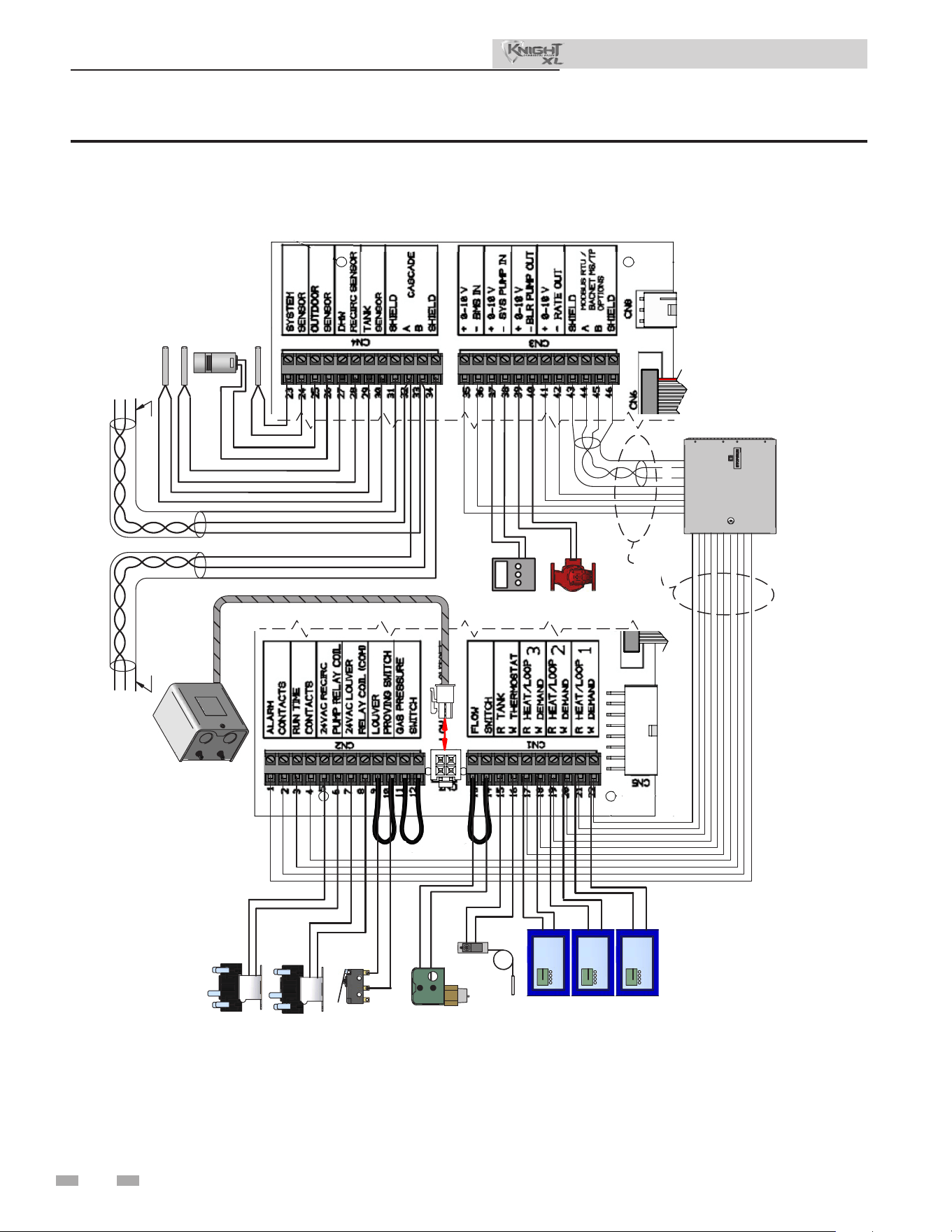
58
9 Field wiring (continued)
Figure 9-3 Low Voltage Field Wiring Connections
Installation & Operation Manual
LOUVER RELAY
FLOW SWITCH
TANK THERMOSTAT
ROOM THERMOSTAT 3
SYSTEM SUPPLY SENSOR
BUILDING
MANAGEMENT
SYSTEM
LOUVER
PROVING SWITCH
COM
NO
LOW WATER
CUTOFF
OUTDOOR SENSOR
SHIELD
SHIELD
TO
NEXT
BOILER
A
B
A
B
FROM
PREVIOUS
BOILER
ROOM THERMOSTAT 1
ROOM THERMOSTAT 2
TANK SENSOR
A
B
NOTE:
CONNECTION BOARD SPLIT FOR
ILLUSTRATION PURPOSES
WIRE AS
NEEDED
SYSTEM PUMP
SPEED
CONTROL
BOILER
PUMP
2000608490 00
RECIRC
PUMP RELAY
DHW RECIRC SENSOR
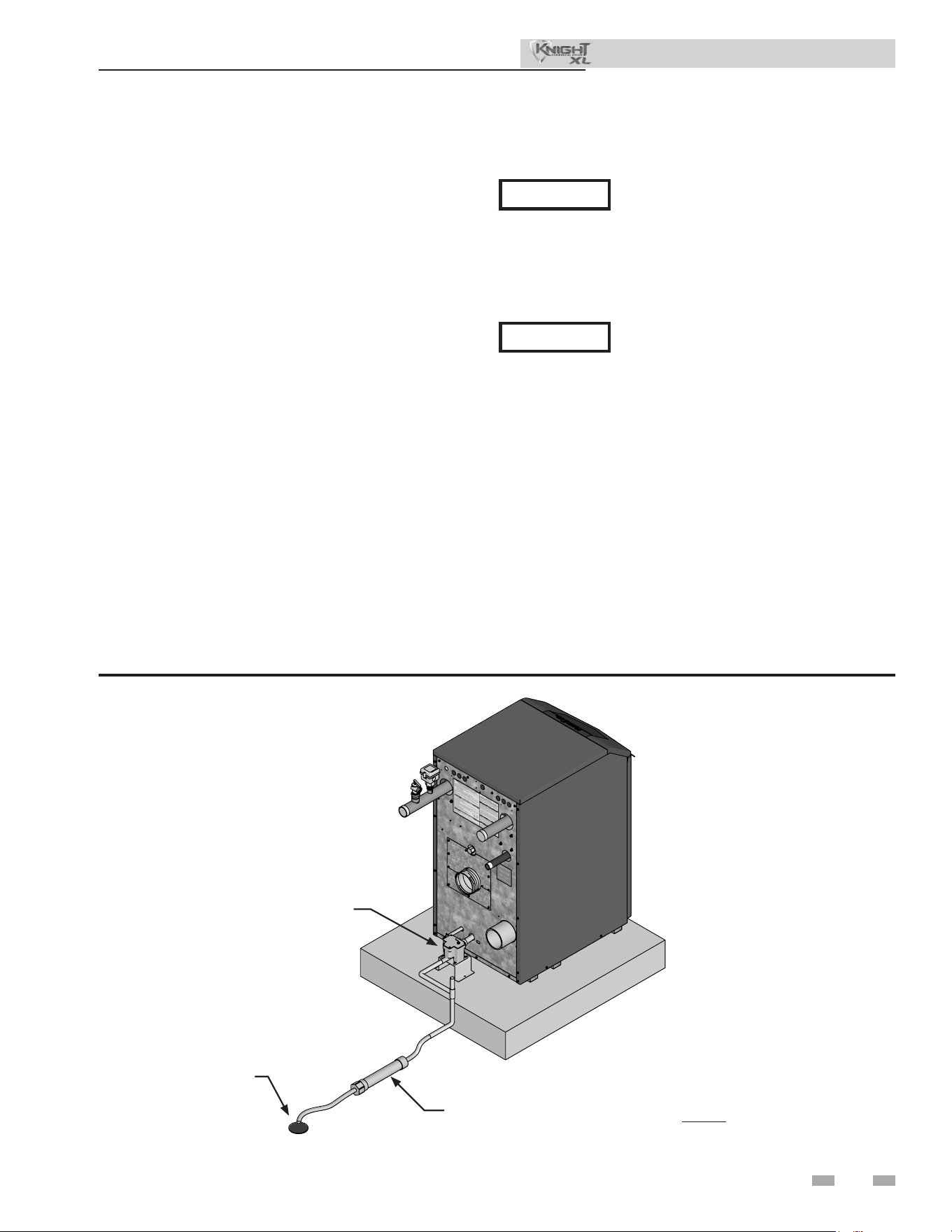
59
10 Condensate disposal
Condensate drain
1. is boiler is a high eciency appliance that produces
condensate.
2. e boiler has a 1/2 inch (12.7 mm) PVC union for
connection of a 1/2 inch (12.7 mm) PVC pipe (FIG.
10-1).
3. Slope condensate tubing down and away from the boiler
into a drain or condensate neutralizing lter. Condensate
from the Knight XL will be slightly acidic (typically with
a pH from 3 to 5). Install a neutralizing lter if required
by local codes.
A Neutralizer Kit (FIG. 10-1) is available from the factory.
4. Do not expose condensate line to freezing temperatures.
5. Use only plastic tubing or piping as a condensate drain
line (FIG. 10-1).
6. A condensate removal pump is required if the boiler is
below the drain. When installing a condensate pump,
select one approved for use with condensing boilers and
furnaces. e pump should have an overow switch to
prevent property damage from condensate spillage. e
switch should be wired in series with the blocked drain
switch inside the boiler (see FIG. 11-1).
Use materials approved by the authority
having jurisdiction. In the absence of other
authority, PVC and CPVC pipe must comply
with ASTM D1785 or D2845. Cement and
primer must comply with ASME D2564 or
F493. For Canada use CSA or ULC certied
PVC or CPVC pipe, ttings, and cement.
NOTICE
NOTICE
To allow for proper drainage on large
horizontal runs, a second line vent may
be required and tubing size may need to
increase to 1 inch (25 mm).
The condensate line must remain
unbstructed, allowing free ow of condensate.
If condensate is allowed to freeze in the line
or if the line is obstructed in any other
manner, condensate can exit from the boiler
tee, resulting in potential water damage to
property.
Figure 9-1 Condensate Disposal
Installation & Operation Manual
NOTE: Neutralizer shown
for illustrative purposes only.
Actual neutralizer may vary.
2000843369 00
FLOOR DRAIN OR
DRAIN PAN
NEUTRALIZER KIT
CONDENSATE TRAP
60
11 Start-up
Installation & Operation Manual
Check/control ll water chemistry
Conduct water quality testing prior to
installing the appliance. Various solutions
are available to adjust water quality.
Hardness between 5 and 12 grains per gallon
1. Consult local water treatment companies for hard water
areas (above 12 grains per gallon hardness).
2. Hardness levels that are above 12 grains/gallon can lead
to lime scale buildup throughout the boiler system. If the
ll water is below 5 grains/gallons, usually due to use of a
water soener, it is recommended to mix in some potable
water at the inlet to increase the hardness of the water to
above 5 grains/gallons.
pH between 6.5 and 8.5
1. pH levels below 6.5 can cause an increase in the rate of
corrosion. pH of 8.5 or higher can potentially cause lime
scale buildup.
Total Dissolved Solids (TDS) less than 350 ppm
1. Total dissolved solids are all minerals, salts, metals, and
charged particles that are dissolved in water.
2. e greater the amounts of TDS present, the higher the
corrosion potential due to increased conductivity in the
water.
Chlorine concentration less than 150 ppm
1. Do not ll boiler or operate with water containing chlorine
in excess of 150 ppm.
2. Filling with fresh drinking water should be acceptable.
3. Do not use the boiler to directly heat swimming pool or spa
water.
Freeze protection uids
IMPORTANT
Fill water
e manufacturer recommends the following for properly
lling your boiler with the appropriate water chemistry for
closed loop boilers. Good ll water quality will help extend
the life of the appliance by reducing the eects of lime scale
buildup and corrosion in closed loop systems.
Ethylene glycol is toxic, DO NOT use as
your freeze protection. Ethylene glycol has a
sweet aroma which children and pets could
mistake as food and ingest; leading to death.
⚠ WARNING
Pre-Commissioning Cleaning
1. Prior to ll and start-up, ush the entire heating system.
2. Clean the entire heating system with an approved pre-
commissioning cleaner (comparable to Sentinel X300
or Fernox F3) in accordance with the manufacturer’s
recommendation to remove debris and prolong the life of
the heat exchanger.
3. Clean all water ltering devices in the system.
4. Flush the cleaning solution out of the entire system and
rell.
Boiler water
BOILER WATER CHEMISTRY
Specication Range
Dissolved Solids < 2000 ppm
pH Level 6.5 to 9.5
Chloride < 150 ppm
• Monitoring pH, chlorides, TDS, and hardness
levels can prolong the life of the appliance by reducing
lime scale buildup, corrosion, and erosion. Check for
leaks to ensure that fresh water is not entering the
system.
• Continual fresh makeup water will reduce boiler life.
• Mineral buildup in the heat exchanger reduces heat
transfer, overheats the stainless steel heat exchanger,
and causes failure.
• e addition of oxygen carried in by makeup water
can cause internal corrosion in system components.
• Leaks in the boiler or piping must be repaired at
once to prevent excessive makeup water. For this
purpose, it is recommended to install a water meter
to easily check the amount of makeup water entering
the system. Makeup water volume should not exceed
5% of the total system volume per year. NOTE: When
makeup water is added, make sure the chemical
additives are added to maintain the correct level.
• An approved multi-metal corrosion inhibitor
(comparable to Sentinel X100 or Fernox F1) is
recommended at the correct concentration and in the
manner recommended by the manufacturer.
CAUTION
Do not use petroleum based cleaning or
sealing compounds in the boiler system.
Gaskets and seals in the system may be
damaged. is can result in substantial
property damage.
DO NOT use "homemade cures" or "boiler
patent medicines". Serious damage to
boiler, personnel, and/or property may
result.
Table 11A Boiler Water Chemistry
1. Use glycol only if needed for freeze protection uid.
2. Propylene glycol is the recommended freeze protection
uid.
3. Make sure to ush the boiler system before adding glycol.
4. Determine the freeze protection uid quantity using
system water content, following the uid manufacturer's
instructions. Boiler water content is listed on page 7.
Remember to include expansion tank water content.
5. Local codes may require a backow preventer or actual
disconnect from city water supply.
6. When using freeze protection uid with automatic ll, it is
suggested to install a water meter to monitor water makeup.
Freeze protection uid may leak before the water begins to
leak, causing the concentration to drop, which reduces the
freeze protection level.
7. e freeze protection set points may be lowered when freeze
protection uid is used (see the Knight XL Service Manual).
8. Consult the glycol manufacturer for details on the suggested
mix of glycol and water for the desired freeze protection
level and the de-rate eect it will have on the boiler output.
Test / replace freeze protection uid
1. For systems using freeze protection uids, follow the uid
manufacturer's instructions.
2. Freeze protection uid must be replaced periodically due to
degradation of inhibitors over time.
3. It is recommended to test the glycol concentration annually
and adjust within the desired set points.
11 Start-up
Installation & Operation Manual
Oxygen prevention
Dissolved oxygen can have a negative eect on the boiler
system. Oxygen can cause iron oxide to generate iron deposits.
Oxygen may also increase the rate of corrosion on non-stainless
steel parts of the system. A low pH level combined with oxygen
further enhances its corrosive eects. Aer boiler installation,
check for air leaks in the following areas:
• Suction gasket
• Pump
• Air valve
• O-ring gaskets
Precautions include installing a water meter to evaluate the fresh
water volume entering the system (should be no more than
5% system volume). Additional volumes of fresh water could
indicate that a leak is present.
Fill and test water system
1. Fill system only aer ensuring the water meets the
requirements of this manual.
2. Close automatic and manual air vents and boiler drain
valve.
3. Fill to correct system pressure. Correct pressure will vary
with each application.
a. e minimum cold water ll pressure for a system is
12 psi.
b. Pressure will rise when the boiler is turned ON and
system water temperature increases.
4. At initial ll and during boiler startup and testing, check
the system thoroughly for any leaks. Repair all leaks before
proceeding further.
Purge air from water system
1. Purge air from system:
a. Connect a hose to the purge valve (see purge/drain
valve in the piping diagrams in this manual). Route the
hose to an area where water can drain and be seen.
b. Close the boiler or system isolation valve between the
purge valve and ll connection to the system.
c. Close zone isolation valves.
d. Open the quick-ll valve on the cold water makeup
line.
e. Open purge valve.
f. Open the isolation valves one zone at a time. Allow
water to run through the zone, pushing out the air.
Run until no noticeable air ow is present. Close
the zone isolation valves and proceed with the next
zone. Follow this procedure until all zones are purged.
g. Close the quick-ll water valve and purge valve and
remove the hose. Open all isolation valves. Watch that
system pressure rises to correct cold-ll pressure.
h. Aer the system has operated for a while, eliminate
any residual air by using the manual air vents located
throughout the system.
i. If purge valves are not installed in the system, open the
manual air vents in the system one at a time, beginning
with the lowest oor. Close the vent when water
squirts out. Repeat with remaining vents.
2. Open the automatic air vent (diaphragm-type or bladder
type expansion tank systems only) one turn.
3. Open other vents:
a. Starting on the lowest oor, open air vents one at a
time until water squirts out.
b. Repeat with remaining vents.
4. Rell to correct pressure.
CAUTION
Eliminate all system leaks. Continual
fresh makeup water will reduce boiler
61
life. Minerals can build up in the heat exchanger, reducing
heat transfer, overheating the heat exchanger, and causing heat
exchanger failure.
62
11 Start-up (continued)
Check for gas leaks
Before starting the boiler, and during
initial operation, smell near the oor and
around the boiler for gas odorant or any
unusual odor. Remove the top access
panel and smell the interior of the boiler
enclosure. Do not proceed with startup
if there is any indication of a gas leak.
Use an approved leak detection solution.
Repair any leaks at once.
DO NOT adjust gas valve outlet pressure.
e gas valve is factory set for the correct
outlet pressure. is setting is suitable
for natural gas and propane, requiring
no eld adjustment. Attempting to
alter the gas valve outlet pressure could
result in damage to the valve, causing
potential severe personal injury, death, or
substantial property damage.
Propane boilers only – Your propane
supplier mixes an odorant with the propane
to make its presence detectable. In some
instances, the odorant can fade, and the
gas may no longer have an odor. Before
startup (and periodically thereaer), have
the propane supplier verify the correct
odorant level in the gas.
Check thermostat circuit(s)
1. Disconnect the two external wires connected to each
of the heat/loop demand terminals on the connection
board.
2. Connect a voltmeter across these two incoming wires.
Close each thermostat, zone valve, and relay in the
external circuit one at a time and check the voltmeter
reading across the incoming wires.
3. ere should NEVER be a voltage reading.
4. If a voltage does occur under any condition, check and
correct the external wiring. (is is a common problem
when using 3-wire zone valves.)
5. Once the external thermostat circuit wiring is checked and
corrected if necessary, reconnect the external thermostat
circuit wires to the connection board. Allow the boiler to
cycle.
⚠ WARNING
⚠ WARNING
⚠ WARNING
Installation & Operation Manual
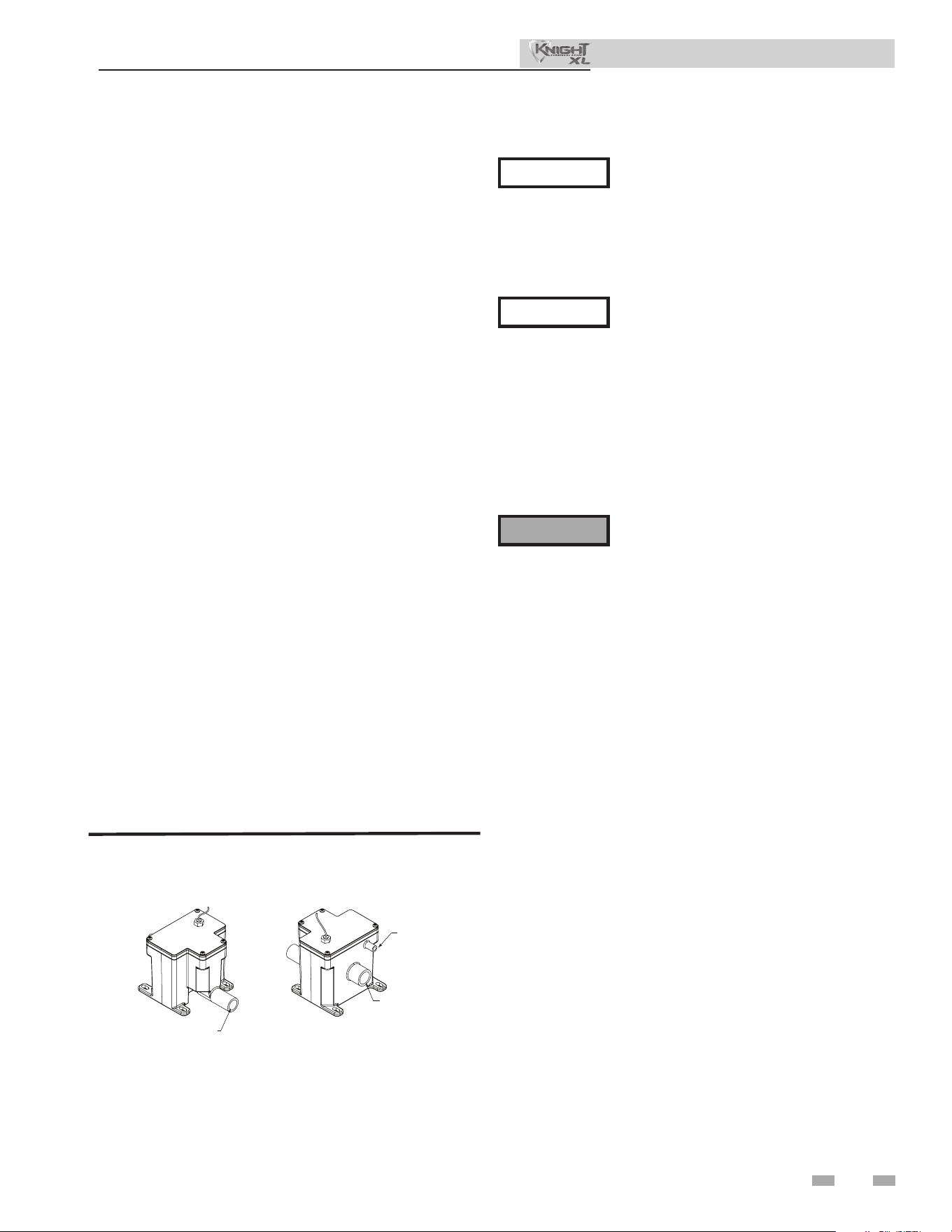
63
11 Start-up
Installation & Operation Manual
Condensate drain
1. is boiler is a high eciency appliance that produces
condensate.
2. e provided condensate trap is equipped with a ball
that acts as a seal against harmful ue gases escaping
in case there is no condensate in the trap. If this ball is
not present, ue gases may be able to pass through the
trap when there is no condensate present, resulting in an
unsafe environment. It is important to check and make
sure the ball is located in the trap, acting as a seal against
ue gases.
3. Connect the condensate trap to the condensate hoses
located on the back of the unit hear the bottom. Use
the hose clamps to secure the connection. Connect the
two-pin molex provided with the condensate trap to the
mating connector on the rear of the boiler.
4. Slope condensate tubing down and away from the boiler
into a drain or condensate neutralizing lter. Condensate
from the Knight XL boiler will be slightly acidic (typically
with a pH from 3 to 5). Install a neutralizing lter if
required by local codes.
A Neutralizer Kit is available from the factory.
5. Do not expose condensate line to freezing temperatures.
6. Use only plastic tubing or piping as a condensate drain
line (FIG. 11-1).
7. A condensate removal pump is required if the boiler is
below the drain. When installing a condensate pump,
select one approved for use with condensing boilers and
furnaces. e pump should have an overow switch to
prevent property damage from condensate spillage. e
switch should be wired in series with the air pressure
switch inside the boiler.
Use materials approved by the authority
having jurisdiction. In the absence of other
authority, PVC and CPVC pipe must comply
with ASTM D1785 or D2845. Cement and
primer must comply with ASME D2564 or
F493. For Canada use CSA or ULC certied
PVC or CPVC pipe, ttings, and cement.
NOTICE
NOTICE
To allow for proper drainage on large
horizontal runs, a second line vent may
be required and tubing size may need to
increase to 1 inch.
The condensate line must remain
unobstructed, allowing free flow of
condensate. If condensate is allowed to
freeze in the line or if the line is obstructed in
any other manner, condensate can exit from
the condensate trap vent opening, resulting
in potential water damage to property.
e condensate trap must have the oat ball
(FIG. 11-1) in place during all times of boiler
operation to avoid ue gas emission from
the condensate drain line. Failure to ensure
the oat ball is in place could result in severe
personal injury or death.
⚠WARNING
Figure 11-1 Condensate Trap
FRONT VIEW
REAR VIEW
DIR #2000507911 00
TO FLOOR DRAIN
OR NEUTRALIZER KIT
1/2” PVC / CPVC CONNECTION
FROM CONDENSATE
VENT ON APPLIANCE
FROM CONDENSATE
DRAIN ON APPLIANCE
64
11 Start-up (continued)
Final checks before starting the boiler
q Read the Knight XL Boiler Service Manual to familiarize
yourself with SMART TOUCH control module operation.
Read the preceding Startup sections in this manual, for
proper steps to start the boiler.
q Verify the preparation procedures have been completed.
q Verify the boiler and system are full of water and all
system components are correctly set for operation.
q Verify electrical connections are correct and securely
attached.
q Inspect vent piping and air piping for signs of deterioration
from corrosion, physical damage, or sagging. Verify air
piping and vent piping are intact and correctly installed
per this manual.
Start the boiler
1. Read and follow the Operating instructions in FIG. 11-2,.
If boiler does not start correctly
1. Check for loose connections, blown fuse or service switch
o?
2. Is boiler water temperature above 200°F (93°C)?
3. Is thermostat set below room temperature?
4. Is gas turned on at meter or boiler?
5. Is incoming gas pressure less than 4 inches w.c. (.99 kPa)?
If none of the above corrects the problem, refer to the
Troubleshooting Section of the Knight XL Service Manual.
Check system and boiler
q Check water piping
1. Check system piping for leaks. If found, shut down the
boiler and repair immediately. (See WARNINGS on
pages 57 through 59 (start-up) regarding failure to repair
leaks.)
2. Vent any remaining air from the system using manual
vents. Air in the system will interfere with circulation
and cause heat distribution problems and noise.
q Check vent piping and air piping
1. Check for gastight seal at every connection, seam of air
piping, and vent piping.
Venting system must be sealed gastight
to prevent ue gas spillage and carbon
monoxide emissions, which will result in
severe personal injury or death.
q Check gas piping
1. Check around the boiler for gas odor following the
procedure on page 48 of this manual (connecting gas
supply piping).
If you discover evidence of any gas leak,
shut down the boiler at once. Find the
leak source with a bubble test and repair
immediately. Do not start the boiler again
until corrected. Failure to comply could
result in severe personal injury, death, or
substantial property damage.
q Propane boilers – verify conversion
1. Verify propane conversion has been completed per the
Propane Conversion instructions.
DO NOT adjust gas valve outlet pressure.
e gas valve is factory-set for the correct
outlet pressure. is setting is suitable
for natural gas and propane, requiring
no eld adjustment. Attempting to
alter the gas valve outlet pressure could
result in damage to the valve, causing
potential severe personal injury, death, or
substantial property damage.
Check ame and combustion
1. Turn the main power o to the boiler by placing the “On/
O” switch in the OFF position.
2. Remove the ue temperature sensor from the ue pipe
connection. NOTE: Combustion measurements will be
made at this point.
3. Turn the main power on to the boiler by placing the “On/
O” switch in the ON position.
⚠ WARNING
⚠ WARNING
⚠ WARNING
⚠ WARNING
Knight XL boilers are typically shipped
ready to re on natural gas. Check boiler
rating plate to determine which fuel the
boiler is set for. If set to natural gas, it
may be converted to LP by installing
an LP venturi and making a gas valve
adjustment (see pages 13 and 14). In order
to operate on LP gas, an LP venturi MUST
BE installed and a gas valve adjustment
MUST BE made. Failure to comply could
result in severe personal injury, death, or
substantial property damage.
Installation & Operation Manual
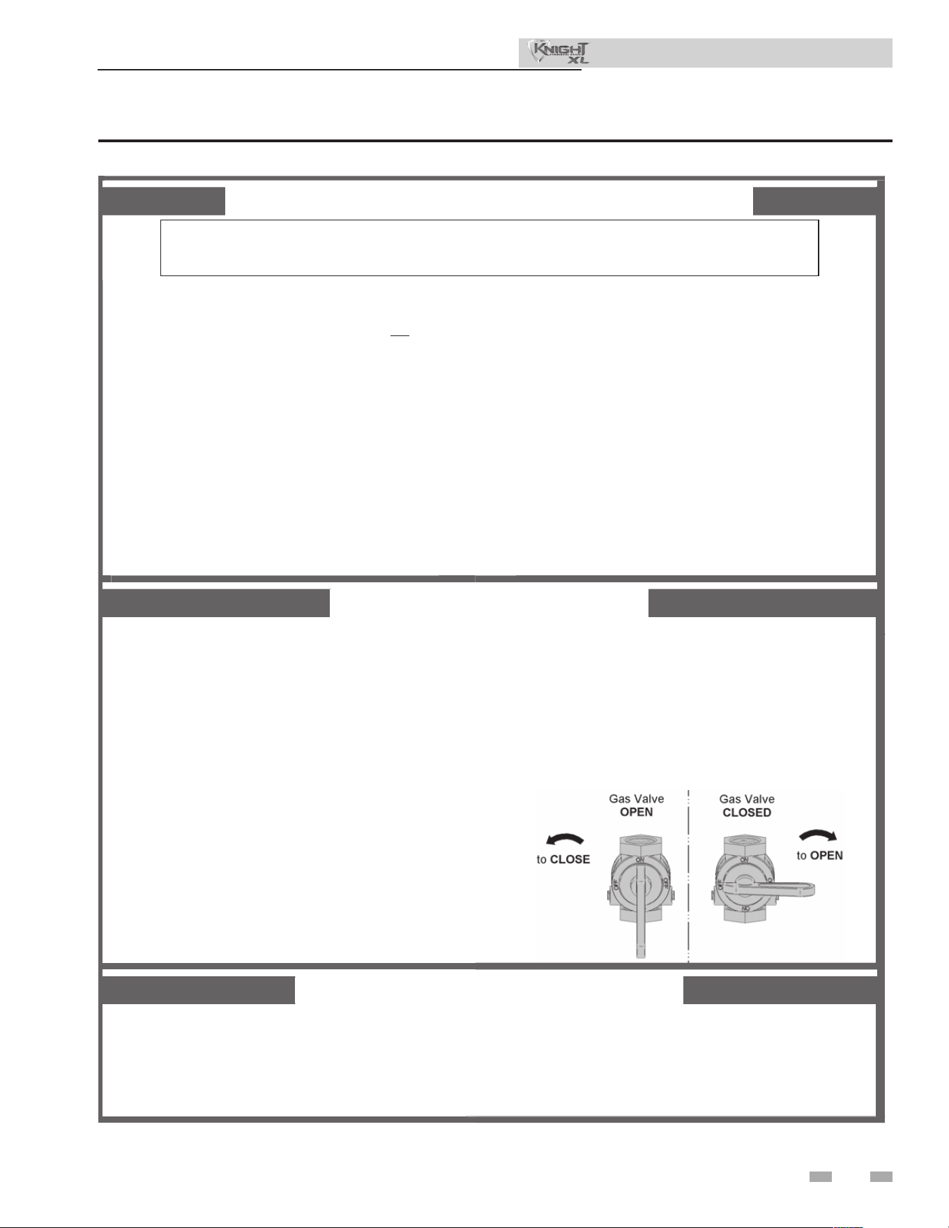
65
FOR YOUR SAFETY READ BEFORE OPERATING
WARNING: If you do not follow these instructions exactly, a fire or explosion
may result causing property damage, personal injury, or loss of life.
A. This appliance does not have a pilot. It is
equipped with an ignition device which
automatically lights the burner. Do not try
to light the burner by hand.
B. BEFORE OPERATING smell all around
the appliance area for gas. Be sure to
smell next to the floor because some gas
is heavier than air and will settle on the
floor.
WHAT TO DO IF YOU SMELL GAS
• Do not try to light any appliance.
• Do not touch any electric switch; do
not use any phone in your building.
• Immediately call your gas supplier from a
neighbor’s phone. Follow the gas supplier’s
instructions.
C. Use only your hand to turn the gas control knob.
Never use tools. If the handle will not turn by
hand, don’t try to repair it, call a qualified service
technician. Force or attempted repair may result
in a fire or explosion.
D. Do not use this appliance if any part has been
under water. Immediately call a qualified
service technician to inspect the appliance and
to replace any part of the control system and
any gas control which has been under water.
• If you cannot reach your gas supplier, call
the fire department.
1. STOP! Read the safety information
above on this label.
2. Set the thermostat to lowest setting.
3. Turn off all electric power to the
appliance.
4. This appliance is equipped with an
ignition device which automatically lights
the burner. Do not try to light the burner
by hand.
5. Remove top cover.
6. Turn gas shutoff valve counterclockwise
to “OFF”. Handle will be perpendicular to
pipe. Do not force.
7. Wait five (5) minutes to clear out any gas.
If you then smell gas, STOP! Follow “B”
in the safety information above on this label.
If you don’t smell gas, go to next step.
8. Turn gas shutoff valve clockwise to “ON”.
Handle will be parallel to pipe.
9. Install top cover.
10. Turn on all electric power to appliance.
11. Set thermostat to desired setting.
12. If the appliance will not operate, follow the
instructions “To Turn Off Gas To Appliance” and
call your service technician or gas supplier.
1. Set the thermostat to lowest setting.
2. Turn off all electric power to the appliance
if service is to be performed.
3. Remove top cover.
4. Turn gas shut off valve counterclockwise to
“OFF”. Handle will be perpendicular to pipe.
Do not force.
5. Install top cover.
LBL2284 REV -
TO TURN OFF GAS TO APPLIANCE
OPERATING INSTRUCTIONS
Figure 11-2 Operating Instructions
11 Start-up
Installation & Operation Manual
66
11 Start-up (continued)
Check ame and combustion (continued)
4. Navigate to the Setup Screen from the Home Screen
by pressing the SETUP button along the le side of the
screen. Enter the installer password.
5. Select the Service Maintenance Screen. e tabs will
scroll (up and down) to reveal more options. See
the Knight XL Service Manual for more detailed
information.
6. Insert the probe from a combustion analyzer into the
hole le by the removal of the ue temperature sensor.
7. Once the boiler has modulated up to full re, measure
the combustion. e values should be in the range
listed in Table 11B below. e CO levels shall be less
than 150 ppm for a properly installed unit.
If the combustion is not within the specied range,
reference the Troubleshooting Section of the Knight
XL Service Manual for possible causes and corrective
actions.
Set space heating operation
Determine controlling sensor
For space heating systems, the temperature control can be
based on one of three sensors; the inlet, outlet, or system
supply sensor. e SMART TOUCH control is programmed
at the factory to control the temperature of the outlet
sensor. e control will automatically switch to the system
supply sensor once it is connected. If it is desired to base
the temperature control on the inlet sensor, the appropriate
parameter must be changed in the control. See the Knight XL
Service Manual for a detailed explanation of this procedure.
Verify space heat circulator mode
e Space Heating Mode controls both the system pump
(if connected), and the boiler pump. When the SMART
TOUCH control receives a space heating call for heat, it
turns on the system pump. If the boiler is not heating an
indirect DHW (Domestic Hot Water) tank, and the set
point is not met, it also turns on the boiler pump. Aer the
space heating call for heat ends, the system pump continues
to run for a short period of time. e system pump can be
programmed to run continuously, except during outdoor
shutdown. If the boiler pump was running, it continues to
run for a short period of time as well. ese pump delays are
factory set to 30 seconds. If dierent delays are desired, the
appropriate parameters in the control must be changed. See
the Knight XL Service Manual for a detailed explanation of
this procedure.
Table 11B Flue Products Chart
8. Once the combustion analysis is complete, test the
safety shuto device by turning the manual shuto
valve to the OFF position and ensuring that the boiler
shuts down and registers an alarm. Turn the manual
shuto switch to the ON position and reset the control.
9. Turn the main power o to the boiler and replace the
ue temperature sensor into the ue pipe connection.
10. Place the boiler back into normal operation.
You must replace the flue gas
temperature sensor to prevent ue gas
spillage into the room. Failure to comply
could result in severe personal injury,
death, or substantial property damage.
⚠ WARNING
Natural Gas Propane
CO
2
O
2
CO
2
O
2
8.4% - 9.4% 4.8% - 6.5% 9.4% - 10.4% 5.4% - 6.9%
Installation & Operation Manual
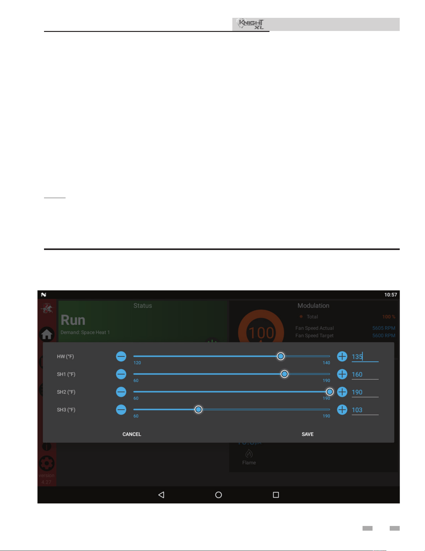
67
Adjust set point temperature(s)
During normal operation, set point temperatures can be
adjusted from the Home Screen by pressing the DETAILS
button on the bottom of the screen (see FIG. 11-3).
1. To change a set point, use the set point slider feature
or the PLUS (+) and MINUS (-) buttons
to adjust the set points as shown in FIG. 11-3.
2. Once the set point has been adjusted to the desired
setting, press the Door Menu slider (top le) or the
Setup button.
3. Press the APPLY CHANGES button on the top of the
screen.
NOTE: e APPLY CHANGES button must be pressed to
complete programming of the controls. Failure to press the
APPLY CHANGES button will result in an unprogrammed
control. e Door Menu button will become highlighted
when there are changes that can be applied.
11 Start-up
Installation & Operation Manual
Figure 11-3 User Set Point Screen
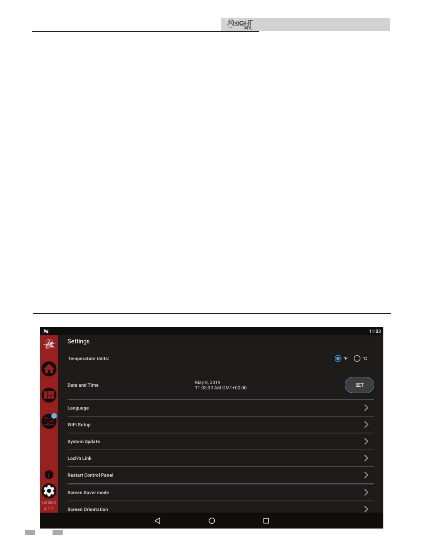
Set domestic hot water (DHW) operation
Verify DHW mode
ere are two (2) modes of operation for DHW. In Normal
Mode, when a DHW demand begins, the control will start
the DHW pump, turn o the boiler pump (if running), and
modulate to bring the outlet temperature to the DHW boiler
set point. e maximum ring rate may be limited in this
mode if desired.
In Zone Mode it is assumed that the indirect DHW tank is
piped as a zone on the primary loop. When a DHW demand
begins, the control will turn on the DHW pump output, and
raise the system temperature set point to the DHW boiler set
point (if higher). e boiler pump will be turned on. e
system pump may be forced on, forced o, or not changed,
depending on the System Pump Mode selected (reference
the Knight XL Service Manual for details). In this mode, any
low temperature zones (such as radiant heating) may need
additional controls to limit the water temperature sent to
those zones.
Set DHW boiler target temperature
When in the DHW Mode, the control will modulate to
maintain the boiler outlet temperature or system supply
temperature to a set point. is set point is set at the factory
to 180°F. If a dierent set point is desired, the appropriate
parameter in the control must be changed. See the Knight XL
Service Manual for a detailed explanation of this procedure.
11 Start-up (continued)
Installation & Operation Manual
Set maximum DHW fan speed
If the rated input of the indirect tank is less than the maximum
output of the boiler, change the maximum DHW fan speed
setting to limit the boiler output accordingly, see the Knight
XL Service Manual for a detailed explanation of this procedure.
Set clock
e SMART TOUCH control has a built-in clock that it uses for
its night setback feature and for logging events. is clock must
be set when the appliance is installed and anytime the appliance
has been powered o for more than one day. Use the following
procedure to set the clock:
1. Press the SETTINGS button under the Lochinvar logo (see
FIG. 8-1).
2. Press the SET button across from the date and time.
3. Proceed to set the date, time, and time zone.
NOTE: Automatic Time Zone will not work.
4. Temperature units and WiFi may also be set here. ese
items may be used to automatically sync the time.
5. Press the Home, View, or Back button to exit.
Figure 11-4 Rapid Setup Screen
68
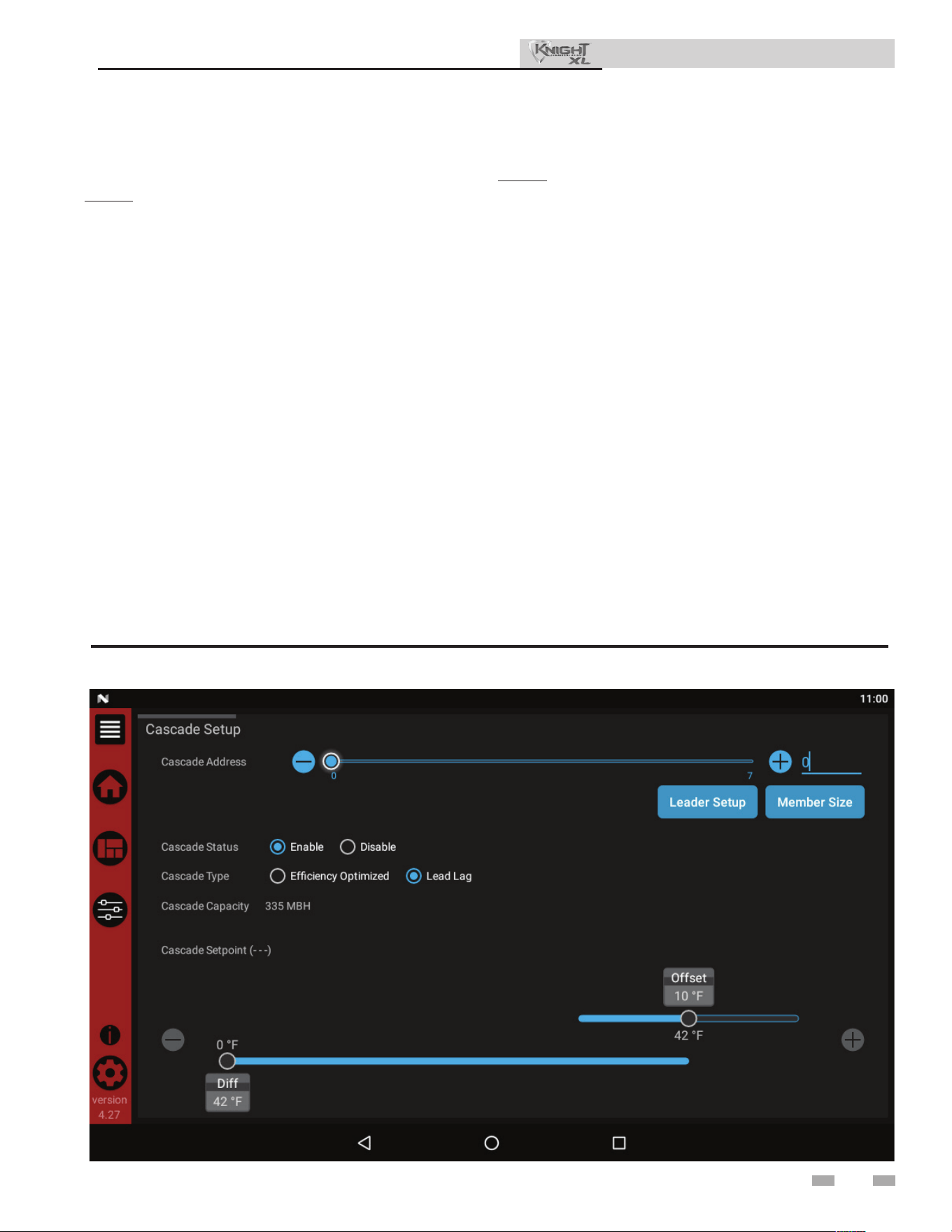
69
Conguration of the cascade
NOTE: For more detailed instructions, please refer to the
Knight XL Service Manual.
When installing a Cascade system, all units must be
programmed for Cascade to operate. Access the Cascade
Setup options as follows:
1. Press the SETUP button on the le side of the display
screen.
2. Enter the installer password.
3. Select the Cascade option as shown in FIG. 11-5.
4. Each unit must have a unique address set. e leader has
more options which are described in the Knight XL
Service Manual.
5. Once all the updates are complete, press the Door Menu
slider (top le) or the Setup button.
6. Press the APPLY CHANGES button on the top of the
screen.
NOTE: e APPLY CHANGES button must be pressed to
complete programming of the controls. Failure to press the
APPLY CHANGES button will result in an unprogrammed
control. e Door Menu button will become highlighted when
there are changes that can be applied.
11 Start-up
Installation & Operation Manual
Figure 11-5 Cascade Screen
General
How the boiler operates
e Knight XL uses an advanced stainless steel heat exchanger
and electronic control module that allows fully condensing
operation. e blower pulls in air and pushes ue products out
of the boiler through the heat exchanger and ue piping. e
control module regulates blower speed to control the boiler
ring rate. e gas valve senses the amount of air owing into
the boiler and allows only the right amount of gas to ow.
How the control module operates
e SMART TOUCH control module receives inputs from
boiler sensors and external devices. e control module
activates and controls the blower and gas valve to regulate
heat input and switches the boiler, Domestic Hot Water
(DHW), and system pumps on and o as needed. e user
programs the module to meet system needs by adjusting control
parameters. ese parameters set operating temperatures and
boiler operating modes. Boiler operation can be based on
boiler outlet water temperature, boiler inlet water temperature,
system temperature, a 0 - 10V signal, or Modbus, depending on
the parameter settings.
Control inputs and outputs
Room thermostat
ere are three (3) heat/loop demand connections available on
this control. ese inputs tell the boiler to provide water for
space heating. Each demand connection has its own set point
and outdoor air reset curve. When multiple demands have a
call for heat the control will give priority to the demand with
the highest set point.
Example: Assume that both heat/loop demand 1 and heat/
loop demand 2 have a call for heat. Demand 1 has a set point
of 110°F. Demand 2 has a set point of 140°F. e boiler will
regulate the system temperature to 140°F until Demand 2 has
been satised. Once Demand 2 has been satisied the boiler
will provide 110°F water to the system.
SMART TOUCH Multi-temp loop control
e Knight XL boiler is capable of producing up to three (3) set
point temperatures to meet dierent space heating demands.
is device controls the temperatures of up to three (3)
separate loops, based on the settings for the three (3) heat/loop
demands (reference Lochinvar kit 100167843).
0 - 10V input (set point or power)
e Knight XL can be controlled by a Building Management
System (BMS) using a 0 - 10 VDC signal. e control can be
congured by the installer to use this signal to either control set
point or ring rate.
e Knight XL can also be programmed to accept a call for heat
from a 0 - 10V signal, reference the Knight XL Service Manual
for a detailed explanation of this procedure.
DHW priority
e SMART TOUCH control allows the connection of a DHW
thermostat or tank sensor to the low voltage connection board.
When a tank sensor is connected, the DHW thermostat input
is ignored. When a boiler is programmed for DHW Normal
Mode, the maximum ring rate can be limited to match the
input rating of the indirect tank coil.
DHW / space heating (SH) cycling
If a DHW call for heat is received while a space heating call is
in progress, and the DHW is in Normal Mode, the control will
start the DHW pump and shut the boiler pump o. e system
pump will remain on. For stand-alone boilers, if the space
heating call is still active while the DHW call is in operation,
the control will wait for 30 minutes (time adjustable by installer)
then it will switch back to the space heating demand. ere is
a timer to switch from space heating to DHW and a timer to
switch from DHW to space heating. e control will switch
back and forth until one of the heat demands end. is function
does not apply to cascade systems.
Programmable controlling sensor
e control module is programmed to use the outlet sensor
as the control sensor by default. If a system supply sensor is
connected, the control automatically uses it as the control
sensor. For stand-alone boilers, the control sensor can be
changed by the installer to the inlet sensor. If the inlet sensor
is chosen as the controlling sensor, it is recommended that the
system supply sensor be installed in the system supply in order
to provide the best control of the inlet temperature.
Anti-cycling
Aer the burner turns o, the control will delay the next burner
cycle for a set time period (time is adjustable by the installer).
e time delay will be bypassed if the inlet water temperature
drops too far during the delay.
Boiler and system pump control
e boiler pump will run whenever the burner is ring, unless
the DHW is programmed for Normal Mode and the boiler is
heating the DHW tank. e boiler pump will run during Freeze
Protection Mode as well. It will continue to run for a short time
aer the burner turns o or the Freeze Protection Mode ends.
e system pump will run whenever there is a space heating call
for heat, or the boiler goes into Freeze Protection Mode. It may
be programmed to run during a DHW call for heat when the
DHW is programmed for Zone Mode. It will continue to run
for a short time aer the end of the heat demand or the Freeze
Protection Mode. e system pump can be programmed to run
continuously if desired, except during outdoor shutdown and/
or a DHW call for heat.
12 Operating information
70
⚠ CAUTION
When multiple temperature loops are
used, mixing valves are required for the
protection of any low temperature loops.
Installation & Operation Manual

71
12 Operating information
Temperature control
Modulation
e Knight XL is capable of modulating its ring rate from a
minimum of 10% to a maximum of 100%. e ring rate is
dictated by the call for heat (i.e., space heating or domestic hot
water), the heating load, ramp delay (if enabled), and various
other temperature limitations.
Ramp delay
For systems with lower ow, the SMART TOUCH can limit
the ring rate (when enabled) when a space heating call for
heat starts, or when switching from a DHW call for heat to a
space heating call for heat. ere are six (6) limits that can be
programmed, as well as six (6) time intervals corresponding to
each limit. e sixth limit will also limit the ring rate for the
rest of the call for heat.
Gradient limiting
If during operation of the boiler the outlet water temperature
is rising too quickly, the control will reduce the ring rate to its
lowest setting.
Outdoor air reset
If an outdoor air sensor is connected, the control module
will calculate the set points of the three (3) space heating
demands based on the programmed reset curves. e installer
can change the slope of the reset curves by several adjustable
parameters. e user can limit the maximum set point for the
system using the space heating set points.
Boost function
If outdoor air reset is active, and any space heating demand
has been active continuously for a set period of time (time
adjustable by installer) and there has been no DHW demands,
the control will increase the set point of that demand by a
xed number of degrees (adjustable by installer). is process
will continue until the space heating demand ends, the set
point reaches the programmed set point or a maximum of
20 increases has occurred. Once the system heat demand is
satised, the set point will revert to the value determined by
the reset curve.
Night setback
e controller may be programmed to reduce the space heating
and DHW set points during certain times each week. Seven
dierent start and stop times may be programmed for the space
heating setback and seven start and stop times for the DHW
setback.
Flame current support
To prevent nuisance shutdowns when the boiler is ring at
minimum rates, the control will increase the ring rate when
the ame signal drops too low.
Protection features
Outlet temperature, ue temperature, and temperature
rise limiting
e outlet temperature is monitored by the boiler outlet
temperature sensor. When the outlet temperature exceeds
185°F, the unit will reduce the fan speed. If the outlet water
temperature exceeds 195°F (90°C) the control will shut the unit
down until it cools o.
e control module monitors the ue temperature by a sensor
located in the ue exhaust. If the ue temperature exceeds
215°F (102°C) the control will reduce the maximum fan speed.
If the ue temperature exceeds 225°F (107°C) the control will
shut the unit down. e unit will restart automatically once the
ue temperature drops 10°F (6°C) and the minimum o time
has expired.
e control monitors the temperature dierence between
the inlet and the outlet sensor. If this dierence exceeds 55°F
(13°C) the control will reduce the maximum fan speed. If the
temperature dierence exceeds 60°F (15°C) the control will
shut the unit down. e unit will restart automatically once the
temperature dierence has dropped below 55°F (13°C) and the
minimum o time has expired.
Freeze protection
DO NOT install the boiler in a room likely to freeze.
Installation & Operation Manual
⚠ DANGER
Freezing Conditions: If this boiler may
have been exposed to freezing conditions,
prevent from ring. Shut o power and
gas to the appliance immediately and
contact the factory for further instructions.
Allowing the boiler to re when the heat
exchanger or near boiler piping is frozen
will result in death or serious injury and
signicant property damage.
e following integral feature of the boiler control module
provides some protection for the boiler only -- not for the
system.
e boiler control module provides a freeze protection
feature with the following attributes:
• Below an inlet temperature of 45°F (7°C), the boiler
pump operates constantly.
• Below an inlet temperature of 37°F (3°C), the burner
res.
• Boiler and pumps turn o if boiler water inlet
temperature rises above 45°F (7°C).
72
12 Operating information (continued)
Monitor external limits
Connections are provided on the connection board for external
limits such as ow switch, low water cuto, gas pressure
switches, and a louver proving switch. e SMART TOUCH
will shut o the burner and inhibit relighting whenever any of
these external limits open.
Run-time and alarm outputs
e boiler provides dry contacts for indicating when the boiler
is running, and when it is unable to operate.
Run-time and cycle counting
e control uses two timers to monitor the total hours of burner
operation. One timer monitors the time the boiler is in the
Space Heating Mode. e other timer monitors the time the
boiler is ring in the DHW Mode.
e control uses two (2) ignition counters to monitor the
amount of boiler cycles. e rst counter counts all ignitions of
the control. e second counter counts only ignition attempts
that have failed.
Service reminder
e control can be programmed for service reminder
notication. is notication will become active when either a
set time frame has expired, or a set amount of running hours or
cycles has expired (all adjustable by the installer). e display
will show a Maintenance Required screen. e installer’s name
and phone number can be programmed into the control. is
information will appear on the Maintenance Required screen.
e service reminder notication can be reset or disabled by
the installer.
e time dependent feature has been disabled by the
manufacturer. To enable this feature change the parameter
to the desired time interval, reference the Knight XL Service
Manual for details regarding parameters.
Error logging
e control will hold in memory the last 10 lockouts as well as
the last 10 blockings. e date and time of the occurrence will
be recorded as well. Only the 10 most current occurrences of
each will be held in memory.
Boiler temperature regulation
Operating temperature (target)
e SMART TOUCH control module senses water temperature
and regulates boiler ring and ring rate to achieve a target
temperature. e target temperature can be set between 70°F
(21°C) and 190°F (88°C).
• Target temperature is xed when the outdoor
sensor is not installed.
• Target temperature is calculated as described
on this page under “Outdoor Reset Operation”
and “Target Temperature Boost” when the
outdoor sensor is connected.
High limit operations
e Knight XL is equipped with adjustable automatic reset and
manual reset high limits. e automatic reset high limit has a
maximum set point of 200°F and the manual reset high limit
has a maximum set point of 210°F.
When the outlet temperature exceeds 200°F, the automatic
high limit action occurs. e boiler shuts down until the outlet
water temperature cools below 190°F, and a 60 second timer
has expired. If the outlet temperature continues to increase, the
manual reset high limit action will occur at 210°F.
High limit test procedure
1. Turn ON the main power to the boiler by placing the
ON/OFF switch in the ON position.
2. Navigate to the Setpoints Screen.
3. Use the slide bar to decrease the MRHL temperature
below the current outlet temperature or to its minimum
setting, whichever is higher.
4. Press the APPLY CHANGES button to save the setting.
5. If the current outlet temperature is above the MRHL
setting then the MRHL will function, causing a boiler
lockout. If the outlet temperature is below the MRHL
setting, navigate to the Service Screen and place the boiler
in service mode at full re.
6. Once the outlet temperature rises above the MRHL
setting, the MRHL will function causing a boiler lockout.
7. Repeat steps 2-4 to set the MRHL to the desired setting
for normal operation.
Installation & Operation Manual
Neither this feature, the boiler control module, nor the use of
glycol eliminates the possibility of freezing. e installation
must still use recognized design, installation, and maintenance
practice to prevent freeze potential for the boiler and system.
NOTICE
When system return temperatures
are maintained below the dew point,
condensation will form on the inside of the
boiler jacket causing some internal sheet
metal components to rust.
e Freeze Protection feature will not work if the appliance
does not have power, is locked out, is in shutdown mode, had a
component failure, or is otherwise prevented from ring.
Freeze protection (continued)
73
12 Operating information
Outdoor reset operation, if used
Target temperature with outdoor reset
is feature improves the system’s eciency as the outdoor
temperature warms up.
See the Knight XL Service Manual to change the settings.
Reset curve
e reset curves look at outdoor air temperature and adjusts
the set points.
Cascade
When multiple boilers are installed, they can be wired
together in a cascade sequence. A maximum of eight boilers
can be controlled from a single control. In this application
one boiler would be designated as the Leader control and all
others would be designated as Member controls. e Leader
control can be programmed to use Lead/Lag or Eciency
Optimization control methods.
Once the Leader boiler receives a call for heat from a room
thermostat, BMS, or Modbus, the control will determine what
the set point will be. If outdoor air reset is desired, connect
the outdoor air sensor to the terminals on the Low Voltage
Connection Board on the Leader boiler. e set point will be
calculated based on the programmed reset curve parameters.
See the Knight XL Service Manual to program the reset curve.
If outdoor air reset is not desired, do not connect the outdoor
air sensor. A xed temperature set point can be programmed
into the control. See the Start-Up section of this manual to
program the set point.
If the water temperature at the system supply sensor is less
than the set point + the turn-o oset - the o-on dierential,
then the control will initiate a call for heat on the Cascade
(see the Knight XL Service Manual for an explanation of
the oset and dierential). e Leader will energize the lead
boiler on the Cascade. For a new startup this will be the
Leader boiler.
DHW, Night Setback, and Ramp Delay operation with
cascade
For normal mode DHW operation any boiler(s) in the Cascade
can be selected to provide heat for a DHW call. Select a boiler
to be designated as the DHW boiler. Connect the DHW
thermostat or sensor to the terminals on the Low Voltage
Connection Board marked for the corresponding device. When
the boiler receives a DHW call, the Leader control will take that
boiler out of the Cascade sequence. If another boiler is available,
the Leader will start it up to take its place.
e DHW boiler will adjust its set point to the programmed
DHW boiler set point and will adjust its ring rate to maintain
this. Once the DHW call has been satised, the Leader control
will place that boiler back into the Cascade sequence.
Switching of the boiler between DHW operation and SH
operation when there is a call for both does not occur in Cascade
Mode.
When DHW is programmed for Zone Mode, connect the DHW
thermostat or tank sensor to the Leader boiler. When a DHW
call is received, the Leader will modulate the entire Cascade to
bring the system supply temperature up to the DHW boiler set
point (if higher).
Night Setback operation of the boilers within the Cascade is
available. Programming of the Night Setback will be done
through the Leader boiler. Refer to the Knight XL Service
manual for information regarding Night Setback.
Ramp Delay operation of the boilers as described in the Knight
XL Service Manual is available when the boilers are part of a
Cascade system.
Sequence of the cascade
To equalize the run time of all boilers on the Cascade, the ring
sequence will automatically be changed at set intervals.
e sequence will be changed once every 24 hours. e
switching on/o sequence will be as follows:
TIME SWITCHING ON SEQUENCE
Start L-M1-M2-M3-M4-M5-M6-M7
1 hour M1-M2-M3-M4-M5-M6-M7-L
2 hours M2-M3-M4-M5-M6-M7-L-M1
If a boiler locks out or is used to heat an indirect DHW tank,
it will automatically be given the lowest priority for the rest of
that 24 hour period.
Low water cuto protection
1. e SMART TOUCH control module uses temperature
sensing of both supply and return areas of the heat
exchanger. If the ow rate is too low or the outlet
temperature too high, the control module modulates and
shuts the boiler down. is ensures boiler shutdown in
the event of low water or low ow conditions.
2. Some codes and jurisdiction may accept these integral
features of the control in lieu of requiring an additional
limit control or low water cuto. Consult local jurisdiction
to determine. A low water cuto is available from the
factory.
Installation & Operation Manual
74
12 Operating information (continued)
Sequence of operation
OPERATION
1. Upon a call for heat, the gas pressure switch(es) must be closed.
2. Once the gas pressure switch(es) are closed, the control turns on the appropriate pumps (system and boiler pumps for
space heating, DHW pump for DHW). The ow switch and/or LWCO must close.
3. The control turns on power to the louver relay. The louver proving switch, air pressure switch, and blocked drain switch
must close.
4. The control starts the prepurge cycle by initiating the blower.
5. The control starts the trial for ignition by ring the spark electrode and opening the gas valve.
6. If ame is not detected after the sparking ends, the control will perform a postpurge, then start another prepurge cycle
and try to light the burner again. On the 500 and larger models, the control will lock out if this second attempt also fails.
On the 400 model, the control will perform a total of 4 attempts before locking out. Once the control has locked the unit
out, the RESET button will need to be pressed on the touch screen LCD.
7. If ame is detected, it holds the ring rate steady for a few seconds to let the ame stabilize, then it begins to modulate
the ring rate based on a set point or some other command (such as a 0-10V BMS signal).
8. If the space heating call for heat is active, and the tank thermostat or sensor starts a DHW call for heat, the boiler will
switch to the DHW mode. If programmed for normal DHW operation (not as a zone), the DHW pump will turn on rst,
then the boiler pump will turn o (boiler and DHW pump operation briey overlap to ensure ow is maintained through the
unit). This will divert the boiler’s outlet water from the heating system and send it to the tank coil instead. The control will
then modulate to maintain the outlet temperature to the DHW boiler set point.
9. If the boiler is not part of a Cascade, and both the space heating and DHW calls for heat remain active long enough, the
boiler will switch back and forth between the two heating modes until one of them is satised.
10. Once both calls for heat are satised, the control will turn o the burner. The blower will continue to run during the
postpurge period.
11. Any pumps that are running will continue to run for their respective pump delay times before turning o, unless
programmed to remain on continuously. A 60 second anti-cycle period will start, which will delay any new call for heat
until it times out.
12. In Standby, ready to start a new cycle.
Installation & Operation Manual
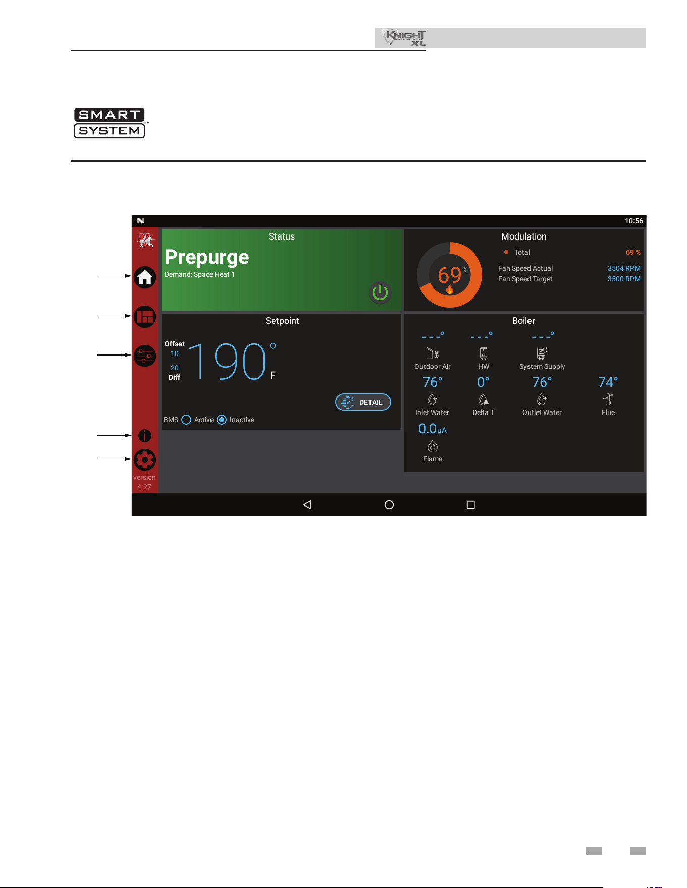
75
12 Operating information
Knight XL control module
Figure 12-1 Control Panel
Use the control panel (FIG. 12-1) to set temperatures, operating conditions, and monitor boiler operation.
Installation & Operation Manual
HOME
VIEW
SETUP
INFORMA
TION
SETTINGS
• e Status Section is located on the top le of the screen
and displays how the unit is currently running (i.e. O,
Stand-by, Blocking, and Lockout) including: current
driving demand, the next Hot Water Setback scheduled,
the reason for any blocking or lockout, and a power button.
• e Demand Section is located on the bottom le of the
screen and displays information about the targets and
limits of the current demand being serviced.
• e Modulation Section is located on the top right of the
screen and displays the target modulation of the unit. is
section also includes target and actual fan speeds.
• e Sensor Section is located on the bottom right of the
screen and displays both factory installed and eld installed
sensor including: Outdoor Air, Hot Water Temperature,
System Supply, System Return, Inlet Water, Delta T, Outlet
Water, Flue Temperature, and Flame Current.
• e Navigation Section is located down the le side of the
screen. ere are ve (5) sections located below the
Lochinvar icon: Home, View, Setup, Information
(About), and Settings. e Home Section is the screen
shown above. e View Section provides more detailed
information including subsections for: History, Cascade,
Graphing, and a complete list of current Sensor Values.
e Setup Section has several screens to aid in setting
up the appliance. e Setup Section includes screens for
adjusting: Set Points, Pump Settings, Cascade, BMS, Ramp
Delay, and Night Setback. e Information Section
provides information about the hardware and soware
including the current soware version of the interface, the
version of the boiler control, and the CON·X·US device
serial number. e Setting Section enables several interface
setup features including: Time Setup, Temperature Unit
Select, Loch’n Link, System Update, and WiFi Setup.
76
Maintenance and annual startup
Table 13A Service and Maintenance Schedules
Service technician
(see the following pages for instructions)
General:
• Address reported problems
• Inspect interior; clean and vacuum if
necessary;
• Clean condensate trap and ll with fresh
water
• Check for leaks (water, gas, ue,
condensate)
• Verify ue and air lines in good condition
and sealed tight
• Check system water pressure/system
piping/expansion tank
• Check ll water meter
• Test boiler water. When test indicates,
clean system water with approved
system restorer following manufacturer’s
information.
• Check control settings
• Check ignition and ame sense
electrodes (sand o any deposits; clean
and reposition)
• Check wiring and connections
• Perform combustion start-up checkout
and performance verication per Section
11 of this manual (CO levels shall be
less than 150 ppm).
• Flame inspection (stable, uniform)
• Flame signal (at least 10 microamps at
high re)
• Clean the heat exchanger if ue
temperature is more than 54°F (30°C)
above return water temperature.
• Test low water ow conditions (reference
the Knight XL Service Manual).
If combustion or performance
indicate need:
• Clean heat exchanger
• Remove and clean burner using
compressed air only
• Clean the blower wheel
ANNUAL START-UP
Owner maintenance
(see the Knight XL User’s Information Manual for
instructions)
Daily
• Check boiler area
• Check pressure/temperature
gauge
Monthly
• Check vent piping
• Check air piping
• Check air and vent termination
screens
• Check relief valve
• Check condensate drain system
• Check air vents
• Check magnetic separator
Periodically
• Test low water cuto (if used)
• Reset button (low water cuto)
Every
6 months
• Check boiler piping (gas and
water) for leaks
• Operate relief valve
End
of season
months
• Shut boiler down (unless boiler
used for domestic hot water)
13 Maintenance
Installation & Operation Manual
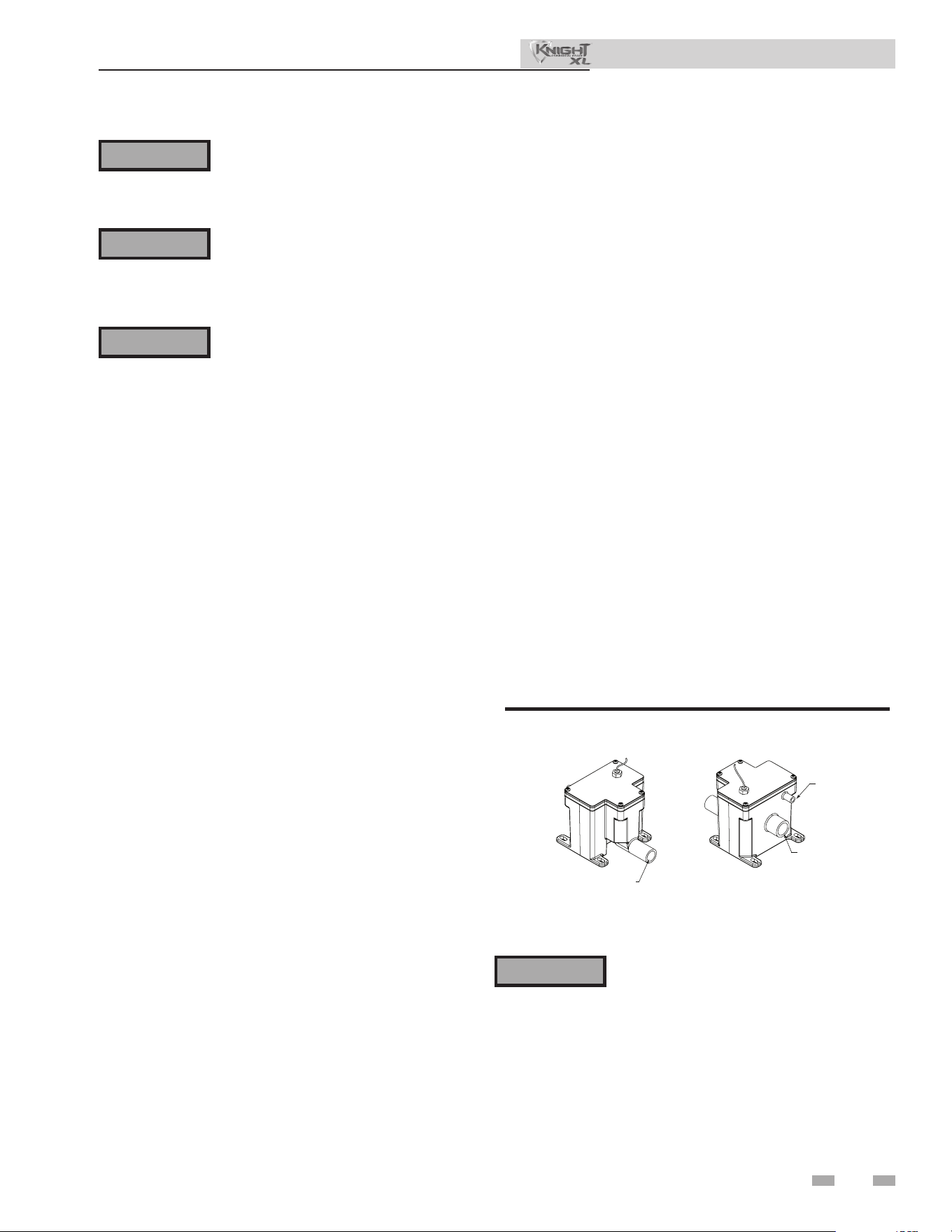
77
13 Maintenance
Follow the Service and maintenance procedures given throughout this manual and in component literature
shipped with the boiler. Failure to perform the service and maintenance could result in damage to the boiler
or system. Failure to follow the directions in this manual and component literature could result in severe
personal injury, death, or substantial property damage.
e boiler should be inspected annually only by a qualied service technician. In addition, the maintenance
and care of the boiler designated in Table 13A and explained on the following pages must be performed to
assure maximum boiler eciency and reliability. Failure to service and maintain the boiler and system could
result in equipment failure.
Electrical shock hazard – Turn o power to the boiler before any service operation on the boiler except as
noted otherwise in this instruction manual. Failure to turn o electrical power could result in electrical shock,
causing severe personal injury or death.
Address reported problems
1. Inspect any problems reported by the owner and correct
before proceeding.
Inspect boiler area
1. Verify that boiler area is free of any combustible materials,
gasoline and other ammable vapors and liquids.
2. Verify that air intake area is free of any of the contaminants
listed in Section 1 of this manual. If any of these are
present in the boiler intake air vicinity, they must be
removed. If they cannot be removed, reinstall the air
and vent lines per this manual and the Knight XL Service
Manual.
Inspect boiler interior
1. Remove the front access cover and inspect the interior of
the boiler.
2. Vacuum any sediment from inside the boiler and
components. Remove any obstructions.
e condensate trap must be lled with
water during all times of boiler operation to
avoid ue gas emission from the condensate
drain line. Failure to ll the trap could result
in severe personal injury or death.
⚠ WARNING
⚠ WARNING
⚠ WARNING
⚠ WARNING
Figure 13-1 Condensate Trap
Installation & Operation Manual
Clean condensate trap
1. Inspect the condensate drain line, condensate PVC
ttings, and condensate trap.
Monthly inspection:
1. e condensate trap should be inspected monthly to
ensure the trap is properly installed and connected to the
condensate pipe under the boiler, see FIG. 13-1.
2. e condensate line should be inspected monthly
for obstructions, making sure it allows free ow for
condensate to drain.
3. Inspect the neutralizing kit (if installed) monthly to
ensure the condensate is draining properly, and there is
still an adequate amount of neutralizing agent available.
Annual cleaning:
1. e condensate trap should be cleaned at least once
annually, or at the end of each heating season, by removing
the bottom cap and cleaning out any sediment that exists.
2. e provided condensate trap is equipped with a ball
that acts as a seal against harmful ue gases escaping in
case there is no condensate in the trap. If this ball is not
present, ue gases may be able to pass through the trap
when there is no condensate present, resulting in an unsafe
environment. It is important to check and make sure the
ball is still located in the trap, acting as a seal against ue
gases at least once annually and aer every cleaning.
3. Aer the condensate trap is cleaned or serviced, it must be
checked to ensure that it is installed and draining properly.
Reference Section 10 - Condensate Disposal for installation
instructions.
FRONT VIEW
REAR VIEW
DIR #2000507911 00
TO FLOOR DRAIN
OR NEUTRALIZER KIT
1/2” PVC / CPVC CONNECTION
FROM CONDENSATE
VENT ON APPLIANCE
FROM CONDENSATE
DRAIN ON APPLIANCE
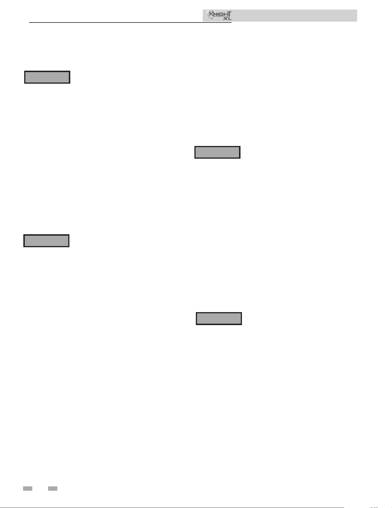
13 Maintenance (continued)
Flue vent system and air piping
1. Visually inspect the entire ue gas venting system and air
piping for blockage, deterioration or leakage. Repair any
joints that show signs of leakage. Verify that air inlet pipe is
connected and properly sealed.
2. Verify that boiler vent discharge and air intake are clean
and free of obstructions.
Failure to inspect for the above conditions
and have them repaired can result in severe
personal injury or death.
Check water system
1. Verify all system components are correctly installed and
operational.
2. Check the cold ll pressure for the system. Verify it is
correct (must be a minimum of 12 psi (82.7 kPa)).
3. Watch the system pressure as the boiler heats up (during
testing) to ensure pressure does not rise too high.
Excessive pressure rise indicates expansion tank sizing or
performance problem.
4. Inspect automatic air vents and air separators. Remove
air vent caps and briey press push valve to ush vent.
Replace caps. Make sure vents do not leak. Replace any
leaking vents.
Check expansion tank
1. Expansion tanks provide space for water to move in
and out as the heating system water expands due to
temperature increase or contracts as the water cools.
Tanks may be open, closed or diaphragm or bladder type.
See Section 7 - Hydronic Piping for suggested best location
of expansion tanks and air eliminators.
Check ll water meter
1. Check ll water meter for water usage. If the amount
exceeds 5% of your system volume, you could have a leak.
Have the system checked for leaks and xed by a qualied
service technician.
Safety relief valves should be re-inspected
AT LEAST ONCE EVERY THREE YEARS,
by a licensed plumbing contractor or
authorized inspection agency, to ensure
that the product has not been aected by
corrosive water conditions and to ensure
that the valve and discharge line have not
been altered or tampered with illegally.
Certain naturally occurring conditions may
corrode the valve or its components over
time, rendering the valve inoperative. Such
conditions are not detectable unless the
valve and its components are physically
removed and inspected. is inspection
must only be conducted by a plumbing
contractor or authorized inspection agency
– not by the owner. Failure to re-inspect the
boiler relief valve as directed could result in
unsafe pressure buildup, which can result in
severe personal injury, death, or substantial
property damage.
Following installation, the valve lever must
be operated AT LEAST ONCE A YEAR to
ensure that waterways are clear. Certain
naturally occurring mineral deposits may
adhere to the valve, rendering it inoperative.
When manually operating the lever, water
will discharge and precautions must be
taken to avoid contact with hot water and
to avoid water damage. Before operating
lever, check to see that a discharge line is
connected to this valve directing the ow of
hot water from the valve to a proper place
of disposal. Otherwise severe personal
injury may result. If no water ows, valve
is inoperative. Shut down the boiler until a
new relief valve has been installed.
2. Aer following the above warning directions, if the relief
valve weeps or will not seat properly, replace the relief valve.
Ensure that the reason for relief valve weeping is the valve
and not over-pressurization of the system due to expansion
tank waterlogging or undersizing.
⚠ WARNING
⚠ WARNING
⚠ WARNING
Eliminate all system or boiler leaks.
Continual fresh makeup water will reduce
1. Inspect all water and gas piping and verify to be leak free.
2. Look for signs of leaking lines and correct any problems
found.
3. Check gas line using the procedure found in Section 8 -
Gas Connections.
Check all piping for leaks
⚠ WARNING
Installation & Operation Manual
Test boiler water
1. Test boiler water. Reference the Knight XL Installation
and Operation Manual for guidelines. When test indicates,
clean system water with approved system restorer following
the manufacturer’s information.
Check boiler relief valve
1. Inspect the relief valve and li the lever to verify ow.
Before operating any relief valve, ensure that it is piped with
its discharge in a safe area to avoid severe scald potential.
Read Section 7 - Hydronic Piping before proceeding
further.
78
boiler life. Minerals can build up in sections, reducing
heat transfer, overheating heat exchanger, and causing heat
exchanger failure. Leaking water may also cause severe
property damage.
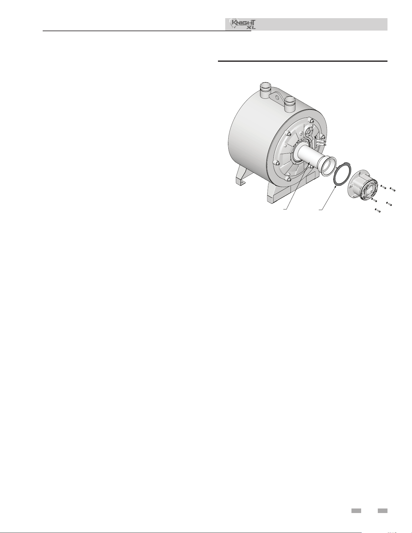
79
13 Maintenance
Inspect ignition and ame sense
electrodes
1. Remove the ignition and ame sense electrodes from the
boiler heat exchanger access cover.
2. Remove any deposits accumulated on the ignition/ame
sense electrode using sandpaper. If the electrodes cannot
be cleaned satisfactorily, replace with new ones.
3. Replace ignition/ame sense electrode, making sure
gasket is in good condition and correctly positioned.
Check ignition ground wiring
1. Inspect boiler ground wire from the heat exchanger
access cover to ground terminal strip.
2. Verify all wiring is in good condition and securely
attached.
3. Check ground continuity of wiring using continuity
meter.
4. Replace ground wires if ground continuity is not
satisfactory.
Check all boiler wiring
1. Inspect all boiler wiring, making sure wires are in good
condition and securely attached.
Check control settings
1. Set the SMART TOUCH control module display to
Parameter Mode and check all settings. See Section
1 of the Knight XL Service Manual. Adjust settings if
necessary. See Section 1 of the Knight XL Service Manual
for adjustment procedures.
2. Check settings of external limit controls (if any) and
adjust if necessary.
Perform start-up and checks
1. Start boiler and perform checks and tests specied in
Section 11 - Start-up.
2. Verify cold ll pressure is correct and that operating
pressure does not go too high.
Check burner ame
1. Inspect ame through observation window.
2. If the ame is unsatisfactory at either high re or low re,
turn o boiler and allow boiler to cool down. Remove the
burner and clean it thoroughly using a vacuum cleaner
or compressed air. Do not use compressed air to clean
burner if performed inside a building.
3. Remove the burner, reference FIG.’s 13-2 thru 13-3.
4. When replacing the burner, ensure gasket is in good
condition and positioned correctly (FIG.’s 13-2 thru
13-3).
DIR #2000585238 00
BURNER
GASKET
Figure 13-2 Burner Assembly - Model 400 - 1000
Installation & Operation Manual
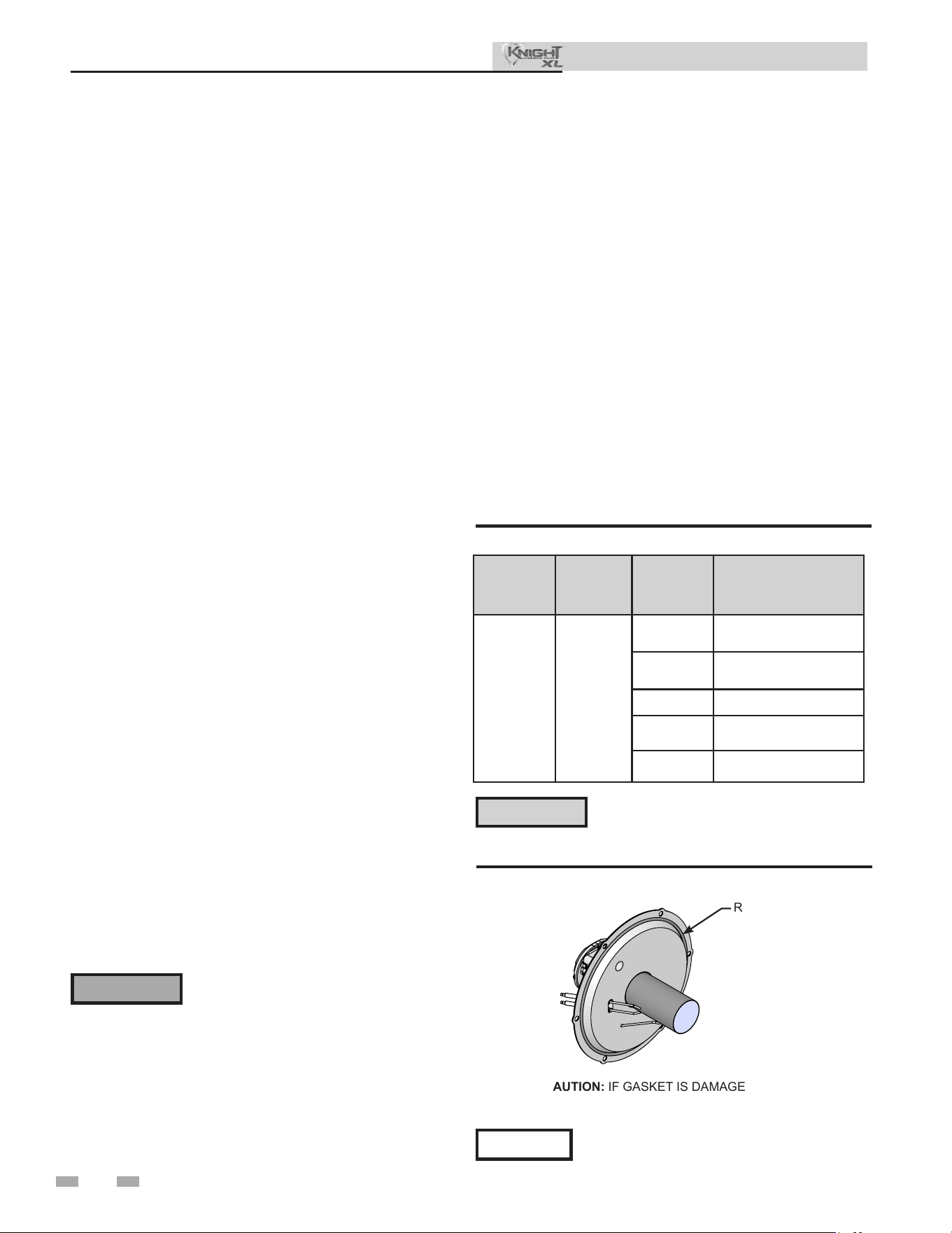
80
13 Maintenance (continued)
Check ame signal
1. At high re the ame signal shown on the display should
be at least 10 microamps.
2. A lower ame signal may indicate a fouled or damaged
ame sense electrode. If cleaning the ame sense electrode
does not improve, ground wiring is in good condition,
and ground continuity is satisfactory, replace the ame
sense electrode.
3. See Section 3 - Troubleshooting in the Knight XL Service
Manual for other procedures to deal with low ame
signal.
Review with owner
1. Review the Knight XL User’s Information Manual with
the owner.
2. Emphasize the need to perform the maintenance schedule
specied in the Knight XL User’s Information Manual
(and in this manual as well).
3. Remind the owner of the need to call a licensed contractor
should the boiler or system exhibit any unusual behavior.
4. Remind the owner to follow the proper shutdown
procedure and to schedule an annual start-up at the
beginning of the next heating season.
The boiler contains ceramic fiber
materials. Use care when handling these
materials per instructions in the Service
Manual. Failure to comply could result in
severe personal injury.
⚠ WARNING
Cleaning boiler heat exchanger
For recommended materials; including brush, appropriate
extension(s), refractory cover, and detailed instructions see
Table 13B - Heat Exchanger Cleaning Kits.
1. Shut down boiler:
• Follow the “To Turn O Gas to Appliance” instructions
for the boiler in Section 11 - Startup.
• Do not drain the boiler unless it will be exposed to
freezing temperatures. If using freeze protection uids
in the system, do not drain.
2. Allow time for the boiler to cool to room temperature if it
has been ring.
3. Remove the nuts securing the heat exchanger access cover
to the heat exchanger and set aside.
4. Remove the heat exchanger access cover, burner, and
gas/air arm assembly.
6. Use a vacuum cleaner to remove any accumulation on the
boiler heating surfaces. Do not use any solvent.
7. Brush the heat exchanger while dry using a nylon bristle
brush. Caution: DO NOT use a metal brush. Re-vacuum
the heat exchanger.
8. Finish cleaning using a clean cloth dampened with warm
water. Rinse out debris with a low pressure water supply.
9. Allow the heat exchanger to thoroughly dry.
10. Remove the eld supplied rear refractory cover from the
back of the combustion chamber of the heat exchanger and
reassemble.
11. Close isolation valves on piping to isolate boiler from
system. Attach a hose to the boiler drain and ush boiler
thoroughly with clean water by using purging valves to
allow water to ow through the water make-up line to the
boiler.
12. Perform start-up and check-out procedures in the Check
Flame and Combustion - Section 11 - Startup of this
manual.
13. Replace the access cover and restore boiler to operation.
Table 13B Heat Exchanger Cleaning Kit
* Do NOT use a metal brush. Only use
the kit provided brush or an equivalent
replacement nylon brush.
⚠ CAUTION
Installation & Operation Manual
NOTICE
Rope gasket is intended for sealing combustion
(FIG. 13-5). If damaged DO NOT reuse, the
rope gasket must be replaced. Consult factory
for replacement rope gasket.
Figure 13-3 Rope Gasket - Heat Exchanger Door
5. Remove the condensate hose from the heat exchanger
end. Connect a eld supplied 3/4" diameter hose to
a drain pan. Using eld supplied means, cover the
refractory in the back of the combustion chamber of the
heat exchanger.
Model
Kit
Number
Part
Number
Component
Description
400 - 1000 100157628
100333410
Rear Refractory Cover,
10.75" Diameter
100208804
Rear Refractory Cover,
7.25" Diameter
100208309* Nylon 4" Wheel Brush*
100208310
1/4" x 12" Drill
Extension
100208311
1/4" x 24" Drill
Extension
CAUTION: IF GASKET IS DAMAGED
DO NOT REUSE, THE GASKET MUST
BE REPLACED.
Rope Gasket
2000620872 01
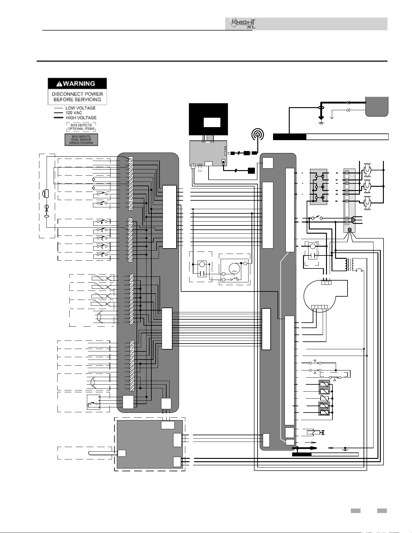
81
Figure 14-1 Wiring Diagram
14 Diagrams
Installation & Operation Manual
BK
BOX DEPICTS
OPTIONAL ITEMS
24 VAC
CN5-6
CN5-13
CN5-12
X4-2
X4-10
X4-11
INTEGRATED
CONTROL
CN5-4 X4-4
SPARK
CONNECTION
BOARD
INLET
SENSOR
OPERATING
FLUE
SENSOR
INTEGRATED
CONTROL
SHIELDED RIBBON CABLE
X7
13
6
2
1
SILENCING
SWITCH
ALARM
BELL
CN6
X6
CN6
X6
CN6
X6
CN6
X6
CN6
X6
CN6
X6
CN6
X6
CN5-2
X4-6
CN5-10
X4-13
CN5-1
X4-7
CN5-9
X4-14
CN6
X6
CN6
X6
CN6
X6
HIGH LIMIT
FLUE
SENSOR
X5-4
X5-12
X5-5
X5-13
X5-14
X5-6
CN6
X6
CN6
X6
CN8-1
X6-1
CN8-2
X6-2
CN8-3 X6-3
X4-1
X9-2
X4-2
X9-1
X4-3
X9-3
S2
S1a
S1b
S3a
S3b
3
4
1
2
M
O
D
B
U
S
9
CN5-14
X4-9
CN5-7 X4-1
13
CN5-11 X4-12
CN5-15 X4-8
CN5-5
X4-3
LOW VOLTAGE
120 VAC
HIGH VOLTAGE
CONNECTION BOARD
21
19
17
15
LWCO
CN7-3
CN7-2
CN7-4
CN7-1
24 VAC
HEAT/LOOP
DEMAND
HEAT/LOOP
DEMAND
3
2
1
HEAT/LOOP
DEMAND
TANK
THERMOSTAT
HIGH GAS
PRESSURE
SWITCH
LOW GAS
PRESSURE
SWITCH
RECIRC PUMP
RELAY COIL
24VAC
5
6
22
20
18
16
11
14
FLOW
SWITCH
120 VAC
120VAC
TERMINAL STRIP
120V SUPPLY "L"
ON / OFF
SWITCH
X1-6
X1-2
F2
NEUTRAL
TERMINAL STRIP
120V SUPPLY "N"
3.15A
F1
A
INTEGRATED CONTROL
GROUND
JUNCTION BOX
BOILER
PUMP
DHW
PUMP
SYSTEM
PUMP
BOILER
PUM
P
CONTACTS
DHW
PUMP
CONTACTS
SYSTEM
PUMP
CONTACTS
L
IN
L
OUT
PUMP RELAYS
X1-1
1 2
BLOWER
SYSTEM PUMP
RELAY
DHW PUMP
RELAY
BOILER PUMP
RELAY
SYSTEM PUMP
RELAY
DHW PUMP
RELAY
BOILER PUMP
RELAY
24V DC
SUPPLY
F3
.8A
X5-1
X5-9
X1-3
X1-4
3
X2-1
GAS VALVE
GAS VALVE
RELAY
X5-7
X5-16
X5-8
X5-15
1
2
4
5
TR2
X1-7
FLAME ROD
ROD
CAUTION HIGH VOLTAGE SPARK LEAD
BLOWER
X2-2
X5-2
X5-11
X5-10
AIR PRESSURE
SWITCH
BLOCKED
DRAIN SWITCH
OPTIONAL
ETHERNET CABLE
E
GND
SW1
J2
J9B
J9A
J12
J4
OPTIONAL USB/WIFI
EXTENSION CABLE
LCD
DISPLAY
24V
J3
J11
COMMUNICATION
CONTROL BOARD
WIFI
DONGLE
X1-7
OR
OR
BR
PR
OR
BR
BR
PR
PR
CN2-4
CN2-1
CN1-5
CN1-6
CN1-3
CN1-4
CN1-1
CN1-2
K1
K2
K3
ON/OFF
SWITCH
JUNCTION
BOX
BK
W
1
2 3 4 5
G
R
R
W
R
T
W
BK
Y/BK
BL
BLOWER
-T
INLET SENSOR S2
FLUE SENSOR S3a
FLUE SENSOR S3b
INTEGRATED
CONTROL
BK
Y
GAS VALVE
@24VAC
SPARK
ROD
TRANSFORMER
TR2
G
HIGH VOLTAGE SPARK LEADCAUTION
FLAME SENSOR
P/BK
Y
W/R
X1-3
X1-4
X1-2
X1-6
X1-5
X1-8
X1-1
X5-7
X5-16
X5-8
X5-15
X5-9
X5-1
X5-2
X5-10
X5-11
X5-4
X5-12
X5-6
X5-5
X5-13
X5-14
X2-2
X2-1
BLOCKED DRAIN SWITCH
O
CN2-2
CN2-3
DHW
PUMP
BOILER
PUMP
SYSTEM
PUMP
120VAC
SUPPLY
L
N
GND
L
IN
L
OUT
X-7
BOX DEPICTS
DUAL SENSOR
SINGLE HOUSING
MODBUS BOARD
MTR-01
X6-3
X6-2
X6-1
X6-4
X9-1
X9-2
X9-3
X9-4
X4-1
X4-2
X4-3
X4-4
X5-1
X5-2
X1-1
X1-2
X1-3
BK
W
G
BL
-T
-T
-T
-T
SHIELD
GROUNDING
JUMPER
O
GY
G
R/BK
W/BK
GY
PR
1
2
G
3
AIR PRESSURE SWITCH
P
O/BK
ALARM
CONTACTS
RUN-TIME
CONTACTS
24
VAC
RECIRC
PUMP RELAY COIL
24 VAC LOUVER
RELAY COIL
LOUVER
PROVING SWITCH
FLOW
SWITCH
TANK
THERMOSTAT
13
14
15
16
17
18
19
20
21
22
0-10V
+
-
BMS
IN
0-10V
+
-
SYS PUMP
IN
0-10V
+
-
BLR PUMP
OUT
0-10V
+
-
RATE
OUT
MODBUS
OPTION
A
B
SHIELD
SHIELD
LOW
WATER
CUT-OFF
24 VAC
COM
1
2
3
4
5
6
7
8
9
10
35
36
37
38
39
40
41
42
43
44
45
46
CN7-1
CN7-2
CN7-3
CN7-4
CONNECTION BOARD
CN8-1
CN8-2
CN8-3
R G
BELL JUMPER
ALARM BELL
SILENCING SWITCH
HEAT/LOOP
DEMAND
3
HEAT/LOOP
DEMAND
2
HEAT/LOOP
DEMAND
1
CN5-1
CN5-9
CN5-2
CN5-10
CN5-16
CN5-3
CN5-11
CN5-5
CN5-4
CN5-12
CN5-15
CN5-13
CN5-
6
CN5-14
BK
BK
BK
BK
BK
BK
BK
BK
BK
BK
BK
BK
BK
CN6
X6
OPTIONAL
ETHERNET CABLE
E
GND
J2
J9B
J9A
J12
J4
J8
OPTIONAL USB/WIFI
EXTENSION CABLE
LCD
DISPLAY
24V
J3
J11
COMMUNICATION
CONTROL BOARD
WIFI
DONGLE
SHIELDED CABLE
DAMPER
RELAY
FLUE DAMPER
3
2
1
M
ALARM
CONTACTS
RUN-TIME
CONTACTS
Notes:
1. All wiring must be installed with local, state, provincial, and national code requirements per either N.E.C. in USA or C.S.A. in Canada.
2. If any original equipment wire as supplied with appliance must be replaced, then it must be replaced with wire having same wire gauge (AWG) and rated for a minimum of 105°C. Exceptions: Replacement high voltage
spark lead and ribbon cables must be purchased from the factory. Use of a non-approved spark lead or ribbon cables can lead to operational problems which could result in non-repairable damage to the integrated controller
or other components.
3. Actual connector block locations may vary from those shown on diagrams. Refer to actual components for proper connector block locations when using diagrams to trouble shoot.
4. Where possible, switches are shown without utilities (gas, water, electricity) connected to the unit. As such, actual switch states may vary from those shown on diagrams depending upon whether utilities are connected or
fault condition is present.
100329773 REV J
RELAY
BLOWER
RELAYBLOWER
FAN
RELAY
PUMP RELAYS
6.3
CN5-3
X4-5
DAMPER RELAY
M
12
3
FLUE DAMPER
OUTLET SENSOR:
OUTLET SENSOR:
OUTLET SENSOR:
OPERATING S1a
OUTLET SENSOR:
HIGH LIMIT S1b
SYSTEM
SENSOR
OUTDOOR
SENSOR
TANK
SENSOR
CASCADE
A
B
SHIELD
SHIELD
DHW RECIRC
SE
N
SOR
0-10V
+
-
BMS
0-10V
+
-
0-10V
+
-
0-10V
+
-
IN
A
B
SHIELD
SHIELD
SYS PUMP
IN
BLR PUMP
OUT
RATE
OUT
MODBUS
GA
23
24
25
26
27
28
29
30
31
32
33
34
S PRESSURE
SWITCH
11
12
CN5-7
LOUVER
PROVING SWITCH
9
10
LOUVER
RELAY COIL
24VAC
7
8
CN5-
16
X5-3
23
24
25
26
27
28
29
30
31
32
33
34
35
36
37
38
39
40
41
42
43
44
45
46
CN6
X6
CN6
X6
CN6
X6
5A
SYSTEM
SENSOR
OUTDOOR
SENSOR
TANK
SENSOR
CASCADE
A
B
SHIELD
SHIELD
DHW RECIRC
SE
N
SOR
X4-5
X4-7
X4-14
X4-6
X4-13
X4-12
X4-3
X4-4
X4-11
X4-8
X4-10
X4-2
X4-9
X4-1
5A
X5-3
12
CN6
X6
OVER-TEMP SWITCH
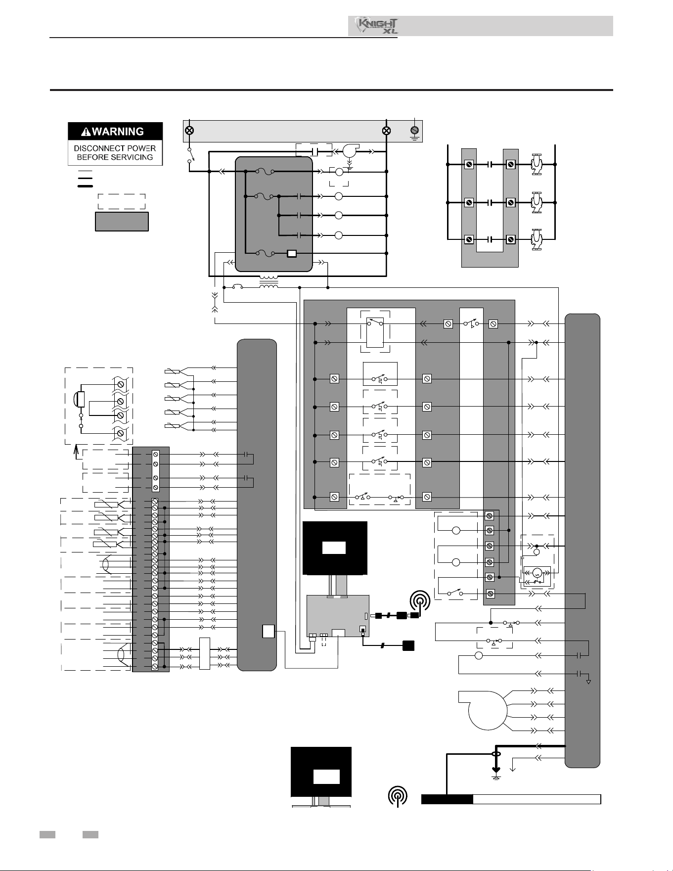
Figure 14-2 Ladder Diagram
14 Diagrams (continued)
82
Installation & Operation Manual
100329773 Rev J
NOTES:
1. Where possible, switches are shown without ulies (gas, water or
electricity) connected to the unit. As such, actual switch states may
vary from those shown on diagrams depending upon whether ulies
are connected or a fault condion is present.
2. See wiring diagram for addional notes.
BK
BOX DEPICTS
OPTIONAL ITEMS
24 VAC
CN5-6
CN5-13
CN5-12
X4-2
X4-10
X4-11
INTEGRATED
CONTROL
CN5-4 X4-4
SPARK
CONNECTION
BOARD
INLET
SENSOR
OPERATING
FLUE
SENSOR
INTEGRATED
CONTROL
SHIELDED RIBBON CABLE
X7
13
6
2
1
SILENCING
SWITCH
ALARM
BELL
CN6
X6
CN6
X6
CN6
X6
CN6
X6
CN6
X6
CN6
X6
CN6
X6
CN5-2
X4-6
CN5-10
X4-13
CN5-1
X4-7
CN5-9
X4-14
CN6
X6
CN6
X6
CN6
X6
HIGH LIMIT
FLUE
SENSOR
X5-4
X5-12
X5-5
X5-13
X5-14
X5-6
CN6
X6
CN6
X6
CN8-1
X6-1
CN8-2
X6-2
CN8-3 X6-3
X4-1
X9-2
X4-2
X9-1
X4-3
X9-3
S2
S1a
S1b
S3a
S3b
3
4
1
2
M
O
D
B
U
S
9
CN5-14
X4-9
CN5-7 X4-1
13
CN5-11 X4-12
CN5-15 X4-8
CN5-5
X4-3
LOW VOLTAGE
120 VAC
HIGH VOLTAGE
CONNECTION BOARD
21
19
17
15
LWCO
CN7-3
CN7-2
CN7-4
CN7-1
24 VAC
HEAT/LOOP
DEMAND
HEAT/LOOP
DEMAND
3
2
1
HEAT/LOOP
DEMAND
TANK
THERMOSTAT
HIGH GAS
PRESSURE
SWITCH
LOW GAS
PRESSURE
SWITCH
RECIRC PUMP
RELAY COIL
24VAC
5
6
22
20
18
16
11
14
FLOW
SWITCH
120 VAC
120VAC
TERMINAL STRIP
120V SUPPLY "L"
ON / OFF
SWITCH
X1-6
X1-2
F2
NEUTRAL
TERMINAL STRIP
120V SUPPLY "N"
3.15A
F1
A
INTEGRATED CONTROL
GROUND
JUNCTION BOX
BOILER
PUMP
DHW
PUMP
SYSTEM
PUMP
BOILER
PUMP
CONTACTS
DHW
PUMP
CONTACTS
SYSTEM
PUMP
CONTACTS
L
IN
L
OUT
PUMP RELAYS
X1-1
1 2
BLOWER
SYSTEM PUMP
RELAY
DHW PUMP
RELAY
BOILER PUMP
RELAY
SYSTEM PUMP
RELAY
DHW PUMP
RELAY
BOILER PUMP
RELAY
24V DC
SUPPLY
F3
.8A
X5-1
X5-9
X1-3
X1-4
3
X2-1
GAS VALVE
GAS VALVE
RELAY
X5-7
X5-16
X5-8
X5-15
1
2
4
5
TR2
X1-7
FLAME ROD
ROD
CAUTION HIGH VOLTAGE SPARK LEAD
BLOWER
X2-2
X5-2
X5-11
X5-10
AIR PRESSURE
SWITCH
BLOCKED
DRAIN SWITCH
OPTIONAL
ETHERNET CABLE
E
GND
SW1
J2
J9B
J9A
J12
J4
OPTIONAL USB/WIFI
EXTENSION CABLE
LCD
DISPLAY
24V
J3
J11
COMMUNICATION
CONTROL BOARD
WIFI
DONGLE
X1-7
OR
OR
BR
PR
OR
BR
BR
PR
PR
CN2-4
CN2-1
CN1-5
CN1-6
CN1-3
CN1-4
CN1-1
CN1-2
K1
K2
K3
ON/OFF
SWITCH
JUNCTION
BOX
BK
W
1 2 3 4 5
G
R
R
W
R
T
W
BK
Y/BK
BL
BLOWER
-T
INLET SENSOR S2
FLUE SENSOR S3a
FLUE SENSOR S3b
INTEGRATED
CONTROL
BK
Y
GAS VALVE
@24VAC
SPARK
ROD
TRANSFORMER
TR2
G
HIGH VOLTAGE SPARK LEADCAUTION
FLAME SENSOR
P/BK
Y
W/R
X1-3
X1-4
X1-2
X1-6
X1-5
X1-8
X1-1
X5-7
X5-16
X5-8
X5-15
X5-9
X5-1
X5-2
X5-10
X5-11
X5-4
X5-12
X5-6
X5-5
X5-13
X5-14
X2-2
X2-1
BLOCKED DRAIN SWITCH
O
CN2-2
CN2-3
DHW
PUMP
BOILER
PU
MP
SYSTEM
PUMP
120VAC
SUPPLY
L
N
GND
L
IN
L
OUT
X-7
BOX DEPICTS
DUAL SENSOR
SINGLE HOUSING
MODBUS BOARD
MTR-01
X6-3
X6-2
X6-1
X6-4
X9-1
X9-2
X9-3
X9-4
X4-1
X4-2
X4-3
X4-4
X5-1
X5-2
X1-1
X1-2
X1-3
BK
W
G
BL
-T
-T
-T
-T
SHIELD
GROUNDING
JUMPER
O
GY
G
R/BK
W/BK
GY
PR
1 2
G
3
AIR PRESSURE SWITCH
P
O/BK
ALARM
CONTACTS
RUN-TIME
CONTACTS
24
VAC
RECIRC
PUMP RELAY COIL
24 VAC LOUVER
RELAY COIL
LOUVER
PROVING SWITCH
FLOW
SWITCH
TANK
THERMOSTAT
13
14
15
16
17
18
19
20
21
22
0-10V
+
-
BMS
IN
0-10V
+
-
SYS PUMP
IN
0-10V
+
-
BLR PUMP
OUT
0-10V
+
-
RATE
OUT
MODBUS
OPTION
A
B
SHIELD
SHIELD
LOW
WATER
CUT-OFF
24 VAC
COM
1
2
3
4
5
6
7
8
9
10
35
36
37
38
39
40
41
42
43
44
45
46
CN7-1
CN7-2
CN7-3
C
N7-4
CONNECTION BOARD
CN8-1
CN8-2
CN8-3
R G
BELL JUMPER
ALARM BELL
SILENCING SWITCH
HEAT/LOOP
DEMAND
3
HEAT/LOOP
DEMAND
2
HEAT/LOOP
DEMAND
1
CN5-1
CN5-9
CN5-2
CN5-10
CN5-16
CN5-3
CN5-11
CN5-5
CN5-4
CN5-12
CN5-15
CN5-13
CN5-
6
CN5-14
BK
BK
BK
BK
BK
BK
BK
BK
BK
BK
BK
BK
BK
CN6
X6
OPTIONAL
ETHERNET CABLE
E
GND
J2
J9B
J9A
J12
J4
J8
OPTIONAL USB/WIFI
EXTENSION CABLE
LCD
DISPLAY
24V
J3
J11
COMMUNICATION
CONTROL BOARD
WIFI
DONGLE
SHIELDED CABLE
DAMPER
RELAY
FLUE DAMPER
3
2
1
M
ALARM
CONTACTS
RUN-TIME
CONTACTS
Notes:
1. All wiring must be installed with local, state, provincial, and national code requirements per either N.E.C. in USA or C.S.A. in Canada.
2. If any original equipment wire as supplied with appliance must be replaced, then it must be replaced with wire having same wire gauge (AWG) and rated for a minimum of 105°C. Exceptions: Replacement high voltage
spark lead and ribbon cables must be purchased from the factory. Use of a non-approved spark lead or ribbon cables can lead to operational problems which could result in non-repairable damage to the integrated controller
or other components.
3. Actual connector block locations may vary from those shown on diagrams. Refer to actual components for proper connector block locations when using diagrams to trouble shoot.
4. Where possible, switches are shown without utilities (gas, water, electricity) connected to the unit. As such, actual switch states may vary from those shown on diagrams depending upon whether utilities are connected or
fault condition is present.
100329773 REV J
RELAY
BLOWER
RELAYBLOWER
FAN
RELAY
PUMP RELAYS
6.3
CN5-3
X4-5
DAMPER RELAY
M
12
3
FLUE DAMPER
OUTLET SENSOR:
OUTLET SENSOR:
OUTLET SENSOR:
OPERATING S1a
OUTLET SENSOR:
HIGH LIMIT S1b
SYSTEM
SENSOR
OUTDOOR
SENSOR
TANK
SENSOR
CASCADE
A
B
SHIELD
SHIELD
DHW RECIRC
SE
N
SOR
0-10V
+
-
BMS
0-10V
+
-
0-10V
+
-
0-10V
+
-
IN
A
B
SHIELD
SHIELD
SYS PUMP
IN
BLR PUMP
OUT
RATE
OUT
MODBUS
GA
23
24
25
26
27
28
29
30
31
32
33
34
S PRESSURE
SWITCH
11
12
CN5-7
LOUVER
PROVING SWITCH
9
10
LOUVER
RELAY COIL
24VAC
7
8
CN5-
16
X5-3
23
24
25
26
27
28
29
30
31
32
33
34
35
36
37
38
39
40
41
42
43
44
45
46
CN6
X6
CN6
X6
CN6
X6
5A
SYSTEM
SENSOR
OUTDOOR
SENSOR
TANK
SENSOR
CASCADE
A
B
SHIELD
SHIELD
DHW RECIRC
SE
N
SOR
X4-5
X4-7
X4-14
X4-6
X4-13
X4-12
X4-3
X4-4
X4-11
X4-8
X4-10
X4-2
X4-9
X4-1
5A
X5-3
12
CN6
X6
OVER-TEMP SWITCH

NOTES

Revision Notes: Revision A (PCP #3000062171 / CN #500048062)
initial release.
Revision B (PCP #3000065127 / CN #500050793) reects updated
gures 14-1 and 14-2.
Revision C (PCP #3000067924 / CN #500053443) reects the removal
of a warning from page 16.
Revision D (PCP #3000068505 / CN #500054027) reects updates to
the wording in step 11 on page 14.
Revision E (PCP #3000069836 / CN #500055226) reects the addition
of the product summary and changing to the max inlet requirements.
100383073_2000837361_Rev E
12/25