3.2.26 357-XXXXX-XX Rev A © Inovonics, 2025 - www.inovonics.com
Inovonics Wired Touchscreen Keypad
Installation Instructions
1 Overview
The Inovonics Intrusion System IDTOUCH1 touchpad connects to the
Gateway Mark II hybrid panel for reliable performance and intuitive control.
Featuring a sleek, high-resolution seven-inch full-color display, it allows
users to easily arm, disarm, and bypass the system while providing real-
time system status and alerts.
1.1 Inovonics Contact Information
If you have any problems with this procedure, contact Inovonics technical
support:
• E-mail: [email protected].
• Phone: (800) 782-2709.
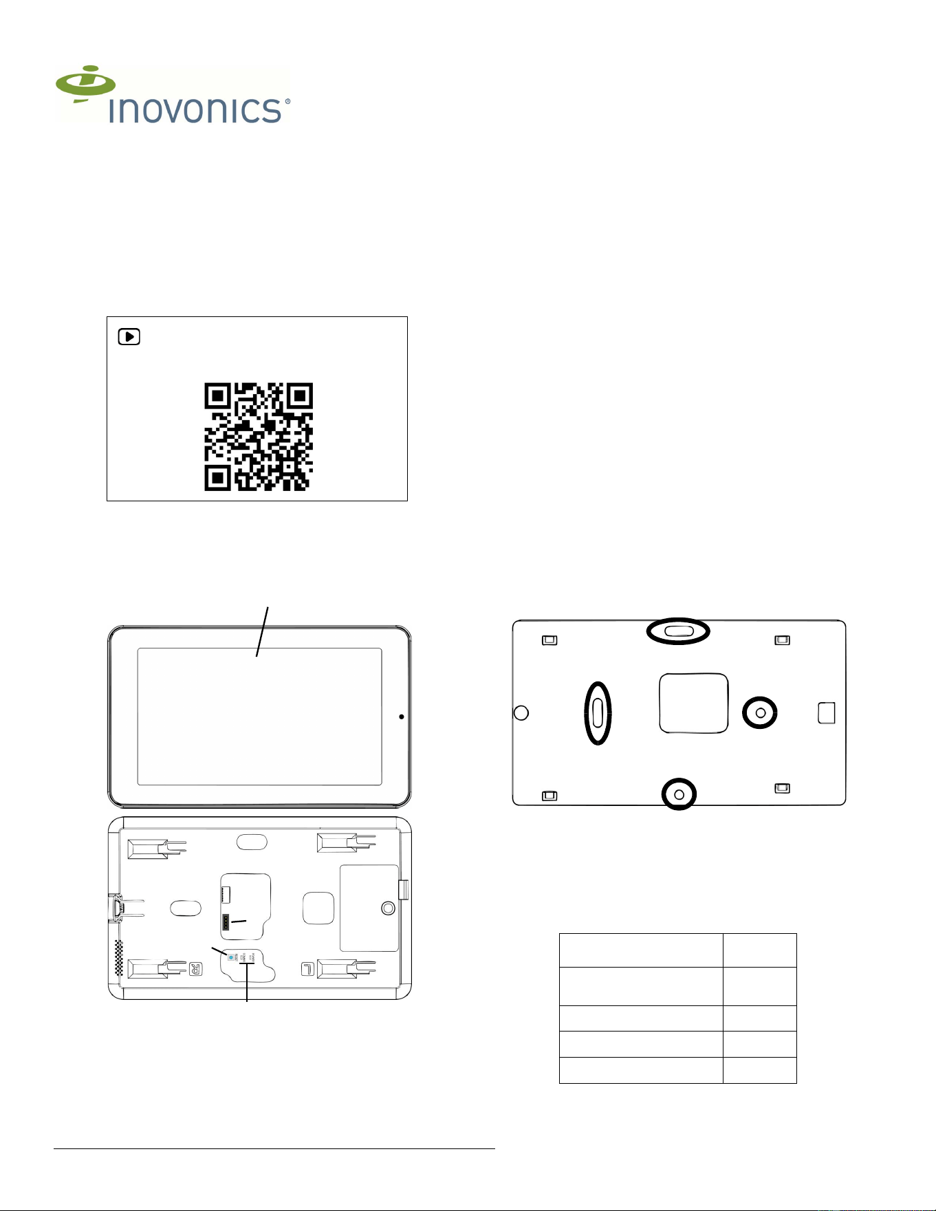
1.2 IDTOUCH1 Touchpad Components
Figure 1 IDTOUCH1 touchpad components
1.3 Operation LEDs
The following LEDs are used to monitor touchpad operation:
POWER: Lit when the touchpad is powered.
COMMS: Lit when communicating with the Gateway Mark II.
1.4 Operation Buttons
The following buttons are used for the touchpad operation:
RESET: Used for a hard reset during troubleshooting.
1.5 Installation Notes
• These products are designed to be installed and maintained by
professional security technicians.
• Products are tested for indoor use.
• All products should be manually tested weekly.
• The Gateway Mark II can only power and backup a single touchpad
and meet the UL 24-hour battery backup requirement.
2 Mounting and Wiring
2.1 Mark and Drill Holes
1. Use the included touchscreen back plate onto the wall and mark two
screw holes and the wire cutout.
• Use a level to ensure the mount is
• When mounting to plasterboard, drill two 7/64 inch (2.5mm) holes.
• When mounting to masonry, drill two 1/4 inch (6mm) holes for the
included wall anchors.
2. If the wire is being fed through the wall, drill an appropriately-sized hole
in the wall for the wire to feed through
2.2 Mount the Touchpad Back Plate
1. Mount the included wall mount back plate to the wall using the included
screws and anchors.
Figure 2 Touchpad back plate mounting holes
2.3 Connect Primary Touchpad to the Gateway Mark II
The Gateway Mark II connection terminal accepts one 16, 18, or 22-gauge
wire, or up to two 18-gauge wires per terminal. Wiring between the graphic
touchpad and the Gateway Mark II must comply with the maximum wiring
length as follows. This cable length is based on a maximum allowed
voltage drop of 3 Vdc at startup.
If a longer run is required, install an additional power supply listed for Fire
Protective Signaling, power limited and regulated (12 VDC nominal), with a
For product and installation videos visit us at
www.inovonics.com/videos or use the QR
code below.
A Touchscreen B Gateway Mark II connection
terminal
C Reset button D LEDs
A
B
C
E
Maximum Cable Run
Wire
Length Between Panel and
Touchpad
Gauge
(AWG)
Less than 150 ft 22
150 - 350 ft 18
350 - 600 ft 16
HVIN:IDTOUCH1
3.2.26 357-XXXXX-XX Rev A © Inovonics, 2025 - www.inovonics.com 2
battery backup at the end of the run at the touchpad. The maximum wire
run length cannot exceed 2500 feet.
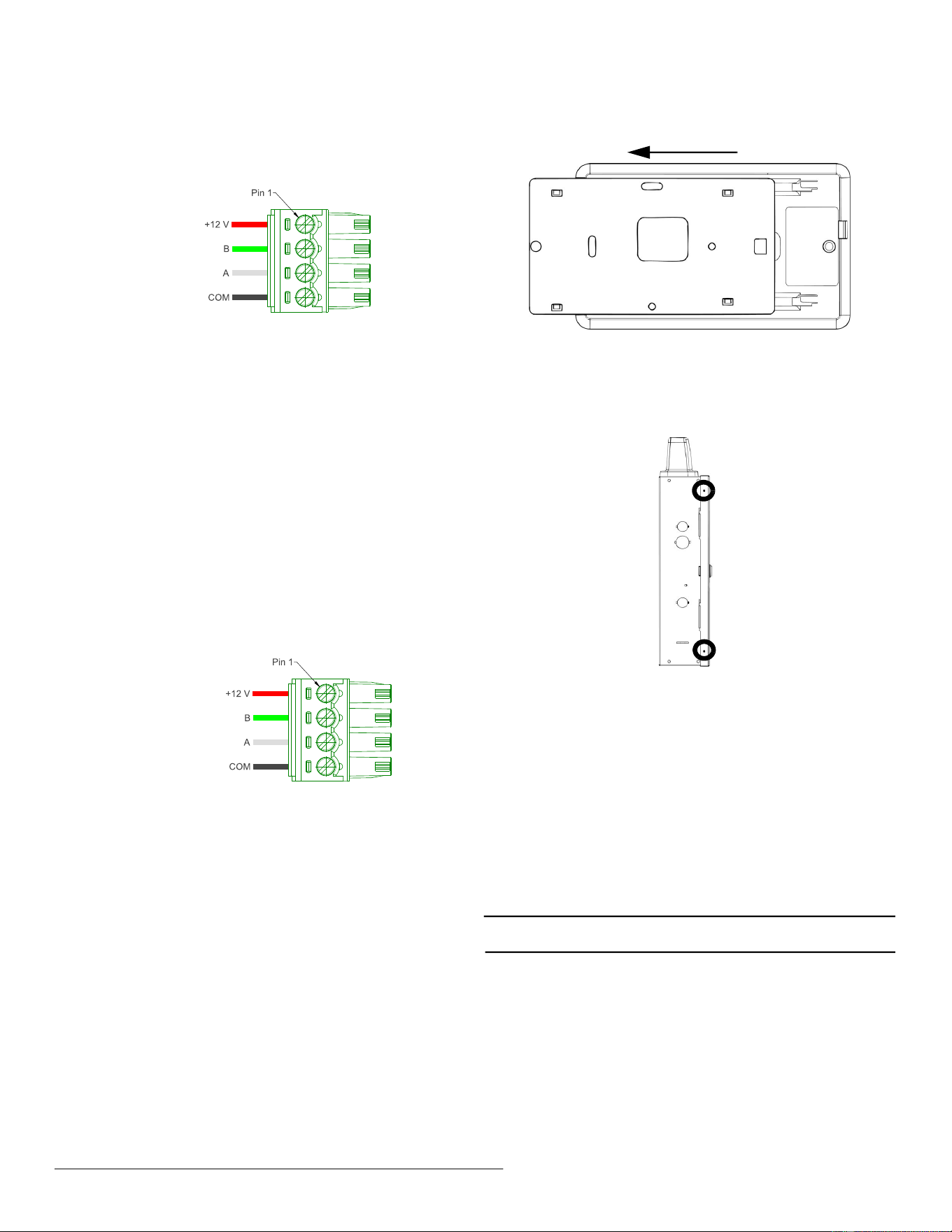
To connect the primary touchpad to the Gateway Mark II:
1. Use the included female connector to wire the touchpad to the Gateway
Mark II as shown in Figure 3, “Connect the primary touchpad to the
Gateway Mark II.”.
Figure 3 Connect the primary touchpad to the Gateway Mark II.
2. Feed cabling through one of the wiring knockouts in the Gateway Mark
II.
3. Connect to one of the Gateway Mark II’s RS485 buses per the Gateway
Mark II Installation and Operation Manual.
3 Connect Additional Touchpads to the Gateway
Mark II
The panel can only power the single primary touchpad. Use appropriately
listed AC to DC power supplies for additional touchpads that meet the
following specifications:
• Input: 100-240V 50/60Hz.
• Output: DC 12V, 1.5A, 18W.
The external power supply ground and panel ground must be connected,
and the last touchpad on a cable run longer than 500 feet must be
terminated.
To connect additional touchpads to the Gateway Mark II:
1. Use the included female connector to wire the touchpad’s data
terminals to the Gateway Mark II as shown in Figure 4, “Connect
additional touchpads to the Gateway Mark II.”
2. Wire the female connector to the power supply as shown in Figure 4,
“Connect additional touchpads to the Gateway Mark II.”.
Figure 4 Connect additional touchpads to the Gateway Mark II.
3. Feed cabling through one of the wiring knockouts in the Gateway Mark
II.
4. Connect the data terminal to one of the Gateway Mark II’s RS485 buses
per the Gateway Mark II Installation and Operation Manual.
5. Connect the power supply terminals to the power supply.
4 Mount the Touchpad to the Back Plate
1. Slide the touchpad onto the back plate in the opposite direction of the
camera until you feel a click.
Figure 5 Install the touchpad onto the back plate
5 Secure the Gateway Mark II Housing
1. Close and lock the housing door.
2. As desired, secure the door shut on one or both sides with a #8 sheet
metal screw.
3. Secure the housing (left side shown)
6 Startup
The IDTOUCH1 Touchpad will start up as soon as power is applied. For
further instructions, see the Inovonics Intrusion System User Guide.
7 Specifications
Dimensions: 7.75" x 4.5" x 0.5".
Weight: 1 lb.
Power requirement: 18W.
WiFi: Wi-Fi 6, WPA-2, 2.5 gHz and 5 gHz.
Operating environment: 32°F (0°C) to 120°F (49°C); 0% to 85% relative
humidity, non condensing.
Storage environment: -40°F (-40°C) to 158°F (70°C); 0% to 85% relative
humidity, non condensing.
Note: Inovonics supports recycling and reuse whenever possible. Please
recycle these parts using a certified electronics recycler.
To panel
To panel
To panel
To panel
To power supply
To panel
To panel
To power supply

FCC Warnning:
This equipment has been tested and found to comply with the limits for a Class B digital device,
pursuant to part 15 of the FCC Rules. These limits are designed to provide
reasonable
protection againstharmful interference in a residential installation. This equipment generates,
uses and can radiateradio
frequency
energy
and,
if
not
installed
and
used
in
accordance
with
the
instructions,
maycause
harmful
interference
to
radio
communications.
However,
there
is
no
guarantee
thatinterference
will
not
occur
in
a
particular
installation.
If
this
equipment
does
cause
harmfulinterference to radio or television reception, which can be
determined by turning the equipmentoff
and
on,
the
user
is
encouraged
to
try
to
correct
the
interference
by
one
or
more
of
thefollowing measures:
•
Reorient or relocate the receiving antenna.
•
Increase the separation between the equipment and receiver.
•
Connect the equipment into an outlet on a circuit different from that to which the receiver is
connected.
• Consult the dealer or an experienced radio/TV technician for help.
Caution:
Any
changes
or
modifications
to
this
device
not
explicitly
approved
by
manufacturer
could void your authority to operate this equipment.
This
device
complies
with
part
15
of
the
FCC
Rules.
Operation
is
subject
to
the
following
two
conditions:
(1)This
device
may
not
cause
harmful
interference,
and
(2)
this
device
must
accept
any
interference received, including interference that may cause undesired operation.
This
equipment
complies
with
FCC
radiation
exposure
limits
set
forth
for
an
uncontrolled
environment.
This
equipment
should
be
installed
and
operated
with
minimum
distance
20cm
between the radiator and your body.

ISED Statement
‐
English:
This device contains licence-exempt transmitter(s)/receiver(s) that
comply with Innovation, Science and Economic
Development Canada’s licence-exempt RSS(s).
Operation is subject to the following two conditions:
(1) This device may not cause interference.
(2) This device must accept any interference, including interference that may cause undesired
operation of the device.
‐
French:Cet appareil contient des émetteurs/récepteurs exempts de licence qui sont
conformes aux CNR exempts de licence d’Innovation, Sciences et
Développement économique
Canada. Le fonctionnement est soumis aux deux conditions suivantes :
(1) Cet appareil ne doit pas causer d’interférences.
(2) Cet appareil doit accepter toute interférence, y compris les interférences susceptibles de
provoquer un fonctionnement indésirable de l’appareil.
This
equipment
complies
with
Canada
radiation
exposure
limits
set
forth
for
an
uncontrolled
environment.
This
equipment
should
be
installed
and
operated
with
minimum
distance
20cm
between
the
radiator & your body.
Cet équipement est conforme Canada limites d'exposition aux radiations dans un environnement
non contrôlé.
Cet équipement doit être installé et utilisé avec une distance minimale de 20 cm entre le
radiateur et votre corps.