TABLE OF CONTENTS
Specifications and Requirements .................................. 2
Electrical Configurations ................................................ 3
Enter Programming ........................................................ 6
Programing Menu Layout ............................................... 6
A Program ...................................................................... 8
B General ....................................................................... 9
C Service Inputs ........................................................... 10
D Service Outputs ........................................................ 10
E Calibration ................................................................. 11
F Service Menu ............................................................ 13
G Counters ................................................................... 15
Operator Training ......................................................... 17
Parts Diagram CBS-1251 ............................................ 22
Parts Diagrams CBS-1252 and CBS-1253 .................. 24
CBS-1251 Tank Assembly ........................................... 26
CBS-1252 and CBS1253 Tank Assembly ................... 28
Quick connect spray head assembly ........................... 32
Wiring Diagrams .......................................................... 33
User’s Guide and Operator Instructions
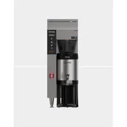
CBS-1251; CBS-1252 and CBS-1253 Extractor Plus Brewing System
FETCO PLUS
®
Commercial Beverage Equipment
CBS-1251 & CBS-1252 1½ gallon brewer with FETCO 1½ Gallon L4D dispensers (sold separately) CBS-2153 2 gallon Extractor Plus Brewers
CONTACT INFORMATION
FETCO® FOOD EQUIPMENT TECHNOLOGIES COMPANY
600 ROSE ROAD
LAKE ZURICH • IL • 60047-0429 • USA
ON THE WEB: fetco.cofee
©2020-2024 FETCO
PATENTS:https://www.fetco.com/pl,pages,patents,74.html
PHONE: (800) 338-2699 (US & CANADA)
(847) 719-3000 (All Countries)
FAX: (847) 719-3001
EMAIL:sales@fetco.com
orders@fetco.com (to order parts and equipment)
techsupp[email protected]om (all service queries)
P213 REV. 002 October 2024
Coffee Brewer: CBS-1250 series
fetco.com
Go to fetco.com for the latest versions of all information Page 2 User Guide & Operator instructions P213 CBS-1250 Pluse0 October 2024
Specifications and Requirements
Water Requirements:
Electrical:
See electrical configuration charts. CBS-1250 series
brewers use a terminal block for electrical connection
CBS-1251; CBS1252 &1253:
20-75 psig, (138-517kPa) 1½gpm/(5.7lpm)
Water inlet fitting
is a 3/8 inch male flare.
Brewer supplied with inlet valve adaptor for BSP to SAE
Tank Temperature, as set by factory:
200°F (93°C) inside water tank (at sea level)
CBS-2151 and CBS-2152
Brew Volume: First Batch 1½ gallons/ 6 liters
Second Batch 1 gallon/ 3.8 liters
CBS-2153 -2 gallon
Brew Volume: First Batch 2 gallons/ 7.6 liters
Second Batch 1 gallon/ 3.8 liters
Water supply: (Optimal) 100-150TDS
All beverage equipment must use filtered water.
Total Brew Cycle—Factory Default Settings
CBS-2151 1½ gal Factory default setting
First batch 1½ gal: 6:30 minutes=[5 minute brew time + 1.30 minute drip delay] + 10% Bypass
Second batch-1 gallon: 5:30 minutes=[4 minute brew time + 1.30 minute drip delay] + 0% Bypass
CBS-2152 1½ gal Factory default setting:
First batch 1½ gal: 6:30 minutes=[5 minute brew time + 1.30 minute drip delay] + 15% Bypass
Second batch-1 gallon: 5:30 minutes=[4 minute brew time + 1.30 minute drip delay] + 0% Bypass
CBS-2153-2 gallon Factory default setting:
First batch 2 gal: 6:30 minutes=[5 minute brew time + 1.30 minute drip delay] + 15% Bypass
Second batch-1 gallon: 5:30 minutes=[4 minute brew time + 1.30 minute drip delay] + 0% Bypass
Brew-Process parameters are user controllable for:
Brew Volume, Brew Time, Prewet Percent, Bypass, Prewet Delay, and Drip Delay
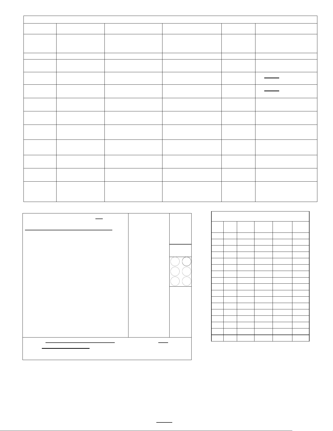
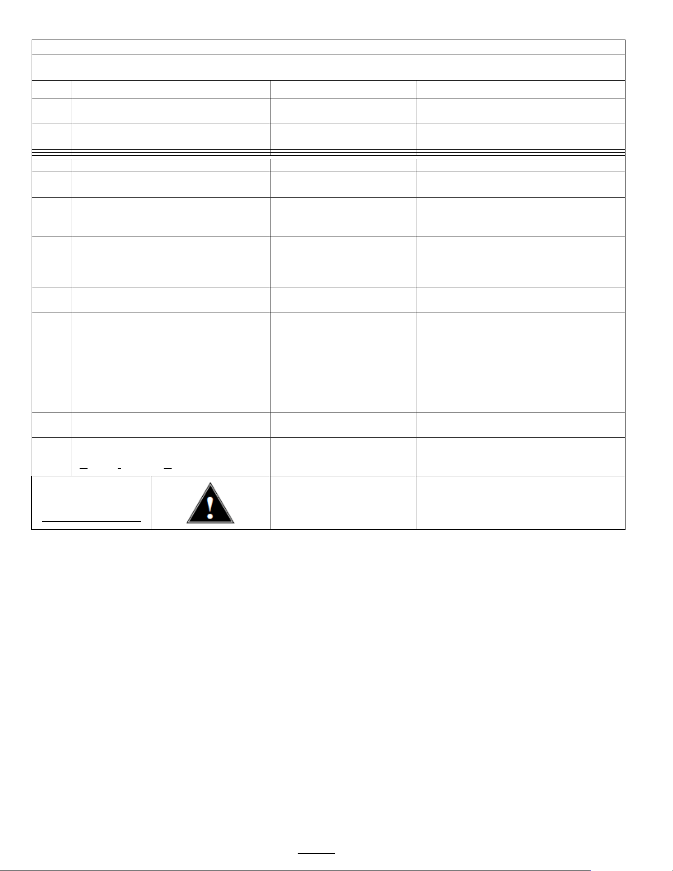
Weights and Capacities
Model Height Width Depth
Water tank
capacity
Empty
Weight
Filled
Weight
Shipping
Weight
Shipping
Dimensions
CBS-1251
1½ gal
36 7/8 in
940 mm
12 3/4 in
320 mm
22 1/2 in
570 mm
6.5 gallon
24.4 L
53 lbs
24 kg
107 lbs
48.3kg
63 lbs
28.6 kg
38” x 18” x 24”
96.5 x 45.7 x 61 cm
CBS-1252
1½ gal
36 7/8 in
940 mm
21 7/8 in
550 mm
22 1/2 in
570 mm
11.1 gallon
42.1 L
77 lbs
35.0 kg
174 lbs
78.9 kg
97 lbs
44 kg
38” x 24” x 27”
96.5 x 61 x 68.6 cm
CBS-1253
2 gal
39 in
99.1 mm
21 7/8 in
550 mm
22 1/2 in
570 mm
11.1 gallon
42.1 L
82 lbs
37.2 kg
180 lbs
81.6 kg
97 lbs
44 kg
40” x 24” x 27”
102 x 61 x 68.6 cm
CBS-1251 & CBS-1252
Calibrated for
1½ gallons/6 liters
CBS-1253
Calibrated for
2 gallons/8 liters
Filter Paper all models
15” X 5 ½ ”– standard
Or use FETCO # F001
Most brewers ship with plastic brew baskets.
See page 31 for other, optional brew baskets
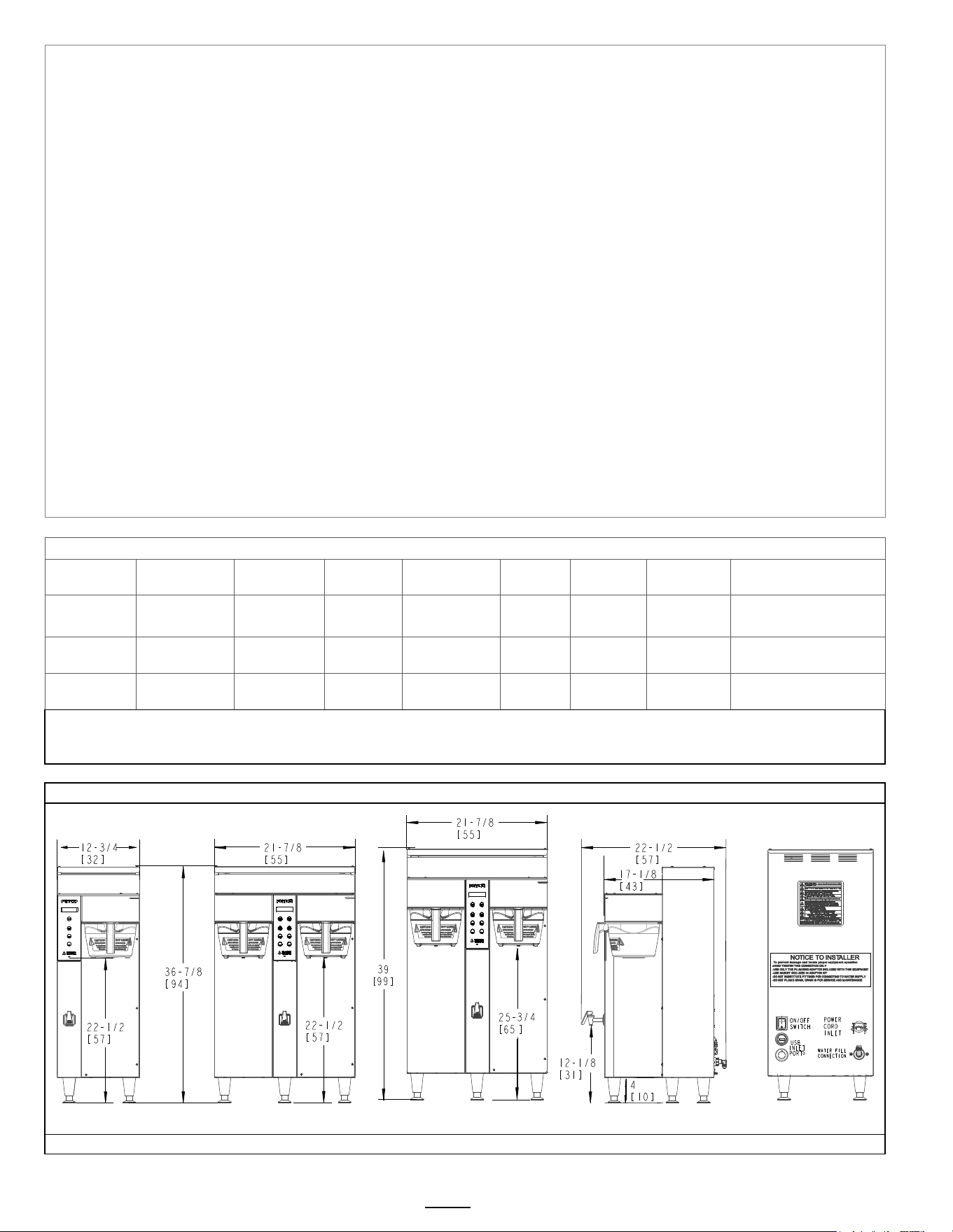
Rough-In Drawings 1201.00053.00 (CBS-1251) 1201.00052.00 (CBS-2152)
[Numbers in parenthesis are centimeters]
CBS-1251 Front CBS-1252 Front CBS-1253 Front Side (all) Back (all)
Go to fetco.com for the latest versions of all information Page 3 User Guide & Operator instructions P213 CBS-1250 Pluse0 October 2024
EXAMPLE: SKU E1253US-UB230-PM110
SKU NUMBER IDENTIFICATION KEY
Product Line
Level Family Region ID Phase Voltage Range # Heaters
IndiviTwin
Heater Wattage
Brew
Basket
Hot Water
Faucet
Bypass
Brew Basket
Locks
Power Cord
E
1
2
5
3
U
S
U
B
2
5
0
P
M
01
1
0
E=extractor
12=PLUS
Series
51=
single side
US =United
States
1 A = 100-120 1 1.5 P=plastic
M=manual 1=Yes 1=Yes 0=Terminal Block
52=
Twin side
IN =
International
2 B = 200-240 2 1.7 M=metal A=automatic 0=no 0=no 1= NEMA 5-15P
53=
Twin side
2 gallon
CE = CE
3
C = 380-415
3
2.3
N=None
2=NEMA 5-20P
NM = NOM
U = 1 or
3
D = 440-480
3.0
3=NEMA 6-15P
X=120 or 240
Twin Voltage
4.0
4=NEMA 6-30P
5.0
5= CEE 7/7 Schuko
6=UK1-13P
7= AUSTRALIAN
8=Brazil
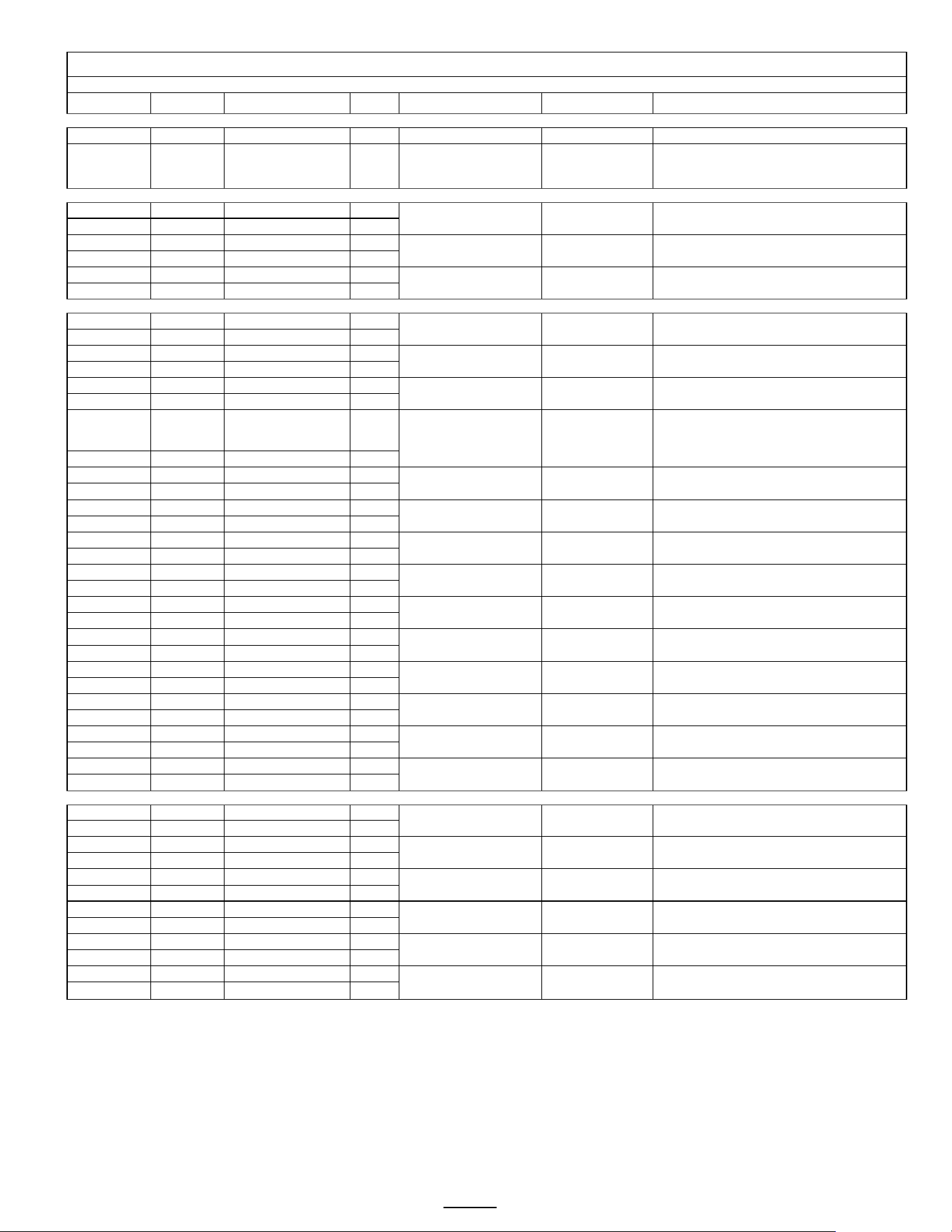
Electrical Configurations CBS-1251 Plus Single Side 1½ gallon brewer
CBS-1251PLUS Single 1½ Gallon-6 Liter Coffee Brewers Domestic and International models
Electrical and Output Specifications All brewers have terminal block electrical utility
Configuration Codes
Heater
Configuration
Voltage Phase Wires KW Amp Draw Brew-Volume/Hour
E1251US-1B230-PM110
2 X 3.0 kW
208-240
1
2+G
4.5-6.0
22.2-25.5
15.0 gal/57 liters
*E1251US-1B230-PM100
2 X 3.0 kW
208-240
1
2+G
4.5-6.0
22.2-25.5
15.0 gal/57 liters
E1251US-1B230-MM110
2 X 3.0 kW
208-240
1
2+G
4.5-6.0
22.2-25.5
15.0 gal/57 liters
E1251IN-1B140-PM110
1 X 4.0 kW
200-240
1
2+G
2.8-4.0
14.4-17.2
10.6 gal/40.3 liters
E1251IN-1B150-PM110
1 X 5.0 kW
200-240
1
2+G
3.5-5.0
17.9-21.3
13.3 gal/50.4liters
E1251IN-1B230-PM110
2 X 3.0 kW
200-240
1
2+G
4.2-6.0
21.3-25.5
15.0 gal/57 liters
*Sold without brew basket lock.
CBS-1251PLUS Single 1½ Gallon-6 Liter Coffee Brewers International models
Electrical and Output Specifications All brewers have terminal block electrical utility connection† 50Hz or 60Hz
Configuration Codes
Heater
Configuration
Voltage Phase Wires KW Amp Draw
Brew-Volume/Hour
E1251NM-1B230-PM110
2 X 3.0 kW
208-240
1
2+G
4.2-6.0
21.3-25.5
15.0 gal/57 liters
E1251KS-1B230-PM110
2 X 3.0 kW
220
1
2+G
5.2
23.4
13.0 gal/49 liters
E1251CE-1B230-PM110
2 X 3.0 kW
230/400
1
2L/N/PE
5.6
12.5
14.9 gal/ 56.4 liters
†*E1251CE-1B130-MM005
1 X 3.0 kW
230
1
L/N/PE
2.8
12.5
7.7 gal/ 29.1 liters
E1251BR-1B230-PM110
2 X 3.0 kW
220
1
L/N/PE
5.2
23.4
13.0 gal/49 liters
*Sold without brew basket lock
†
This equipment includes a factory installed power cord with a CEE 7/7 Schuko plug and does not require installer to connect to the terminal block.
NOTES:
-
Advanced electronics enable this equipment to operate with a 50-60 Hz frequency range without affecting the circuit or requiring user adjustments.
-
NM in SKU suffix (above) denotes equipment with NOM certification, Spanish labeling for Mexico and Spanish language user guide
-
The "KS" in the SKU suffix indicates GCC equipment with CB Scheme certification, labeling for KSA, and Arabic language user guide.
-
The "BR" in the SKU suffix indicates Brazil equipment with CB Scheme certification, Type N plug, labeling and Portuguese for Brazil language user guide.
-The “CE” in the suffix (above) indicates equipment with a current CB scheme supporting CE marking. This equipment is not cUL/UL certified
CBS-1252 Plus Twin 1½ Gallon Coffee Brewers continued on following page
Go to fetco.com for the latest versions of all information Page 4 User Guide & Operator instructions P213 CBS-1250 Pluse0 October 2024
Electrical Configurations CBS-1252 Plus Twin Side 1½ gallon brewer
CBS-1252
Plus
Twin 1½ Gallon-6 Liter Coffee Brewers Field configurable Domestic with cUL/UL & NSF-4 Certification
Electrical and Output Specifications
All brewers have terminal block electrical utility connection 50Hz or 60Hz
Configuration Codes
Heater Configuration
Voltage
Phase
Wires
KW
Amp Draw
Brew Volume/Hour
E1252US-UB230-PM110
Selectable (1 or 3 phase)
Sold as single phase (see pg.34)
2 X 3.0 kW 208-240 1 2+G 4.5-6.0 22.2-25.5 15.9 gal/60.4 liters
3 X 3.0 kW 208-240 3 3+G 6.8-9.0 19.3-22.2 23.9 gal/90.6 liters
E1252US-UB230-MM110
Selectable (1 or 3 phase)
Sold as single phase (see pg.34)
2 X 3.0 kW 208-240 1 2+G 4.5-6.0 22.2-25.5 15.9 gal/60.4 liters
3 X 3.0 kW 208-240 3 3+G 6.8-9.0 19.3-22.2 23.9 gal/90.6 liters
E1252US-UB250-PM110
Selectable (1 or 3 phase)
Sold as single phase (see pg.34)
2 X 5.0 kW 208-240 1 2+G 7.6-10.0 36.6-42.2 25.3 gal/97 liters
3 X 5.0 kW 208-240 3 3+G 11.3-15.0 31.8-36.6 30.0 gal/114 liters
E1252US-UB250-MM110
Selectable (1 or 3 phase)
Sold as single phase (see pg.34)
2 X 5.0 kW 208-240 1 2+G 7.6-10.0 36.6-42.2 25.3 gal/97 liters
3 X 5.0 kW 208-240 3 3+G 11.3-15.0 31.8-36.6 30.0 gal/114 liters
Field configurable brewers are shipped from factory in single phase configuration.
Instructions are provided for licensed installer to configure wiring at terminal block for three phase configuration.
CBS-1252PLUS Twin 1½ Gallon-6 Liter Coffee Brewers Domestic and International models single voltage
With cUL/UL & NSF-4 Certification and listed in a CB test report
Electrical and Output Specifications Single-Voltage. Brewers have terminal block electrical utility connection 50Hz or 60Hz
Configuration Codes Heater Configuration Voltage Phase Wires KW Amp Draw Brew Volume/Hour
E1252IN-1B230-PM110
2 X 3.0 kW
200-240
1
2+G
4.2-6.0
21.3-25.5
15.9 gal/60.4 liters
E1252IN-1B250-PM110
2 X 5.0 kW
200-240
1
2+G
7.0-10.0
35.2-42.2
26.6gal/100.7liters
CBS-1252Plus Twin 1½ Gallon-6 Liter Coffee Brewers Specialty International models NSF-4 Certified
Electrical and Output Specifications All brewers have terminal block electrical utility connection 50Hz or 60Hz
Configuration Codes
Heater Configuration
Voltage
Phase
Wires
KW
Amp Draw
Brew Volume/Hour
E1252IN-3C330-PM110 3 X 3.0 kW
220/380
240/415
3 4+G 7.6-9.0 12.0-12.9 23.9 gal/90.6 liters
E1252IN-3C340-PM110 3 X 4.0 kW
220/380
240/415
3 4+G 10.1-12.0 15.8-17.2 30.0 gal/114 liters
E1252IN-3C350-PM110 3 X 5.0 kW
220/380
240/415
3 4+G 12.6-15.0 19.6-21.3 30.0 gal/114 liters
E1252CE-3C330-PM110
3 X 3.0 kW
230/400
3
3L/N/PE
8.3
12.5
22.1gal/83.6 liters
E1252CE-3C350-PM110
3 X 5.0 kW
230/400
3
3L/N/PE
13.8
20.5
30.0 gal/114 liters
Configuration Codes
Heater Configuration
Voltage
Phase
Wires
KW
Amp Draw
Brew Volume/Hour
Field configurable version
E1252NM-UB250-PM110
Selectable (1 or 3 phase)
Sold as single phase (see pg.34)
2 X 5.0 kW
208-240
1 2+G 7.6-10.0 36.6-42.2 26.6 gal/101 liters
3 X 5.0 kW
208-240
3 3+G 11.3-15.0 31.8-36.6 30.0 gal/114 liters
E1252NM-1B250-PM110 2 X 5.0 kW
200-240
1 2+G 7.0-10.0 35.2-42.2 26.6gal/100.7liters
Single voltage versions
E1252KS-3C330-PM110 3 X 3.0 kW
220/380
240/415
3 4+G 7.6-9.0 12.0-12.9 23.9 gal/90.6 liters
E1252KS-3B330-PM110
3 X 3.0 kW
230/400
3
3L/N/PE
8.3
12.5
22.1gal/83.6 liters
E1252BR-1B250-PM110
2 X 5.0 kW
220
1
L/N/PE
8.5
38.6
27gal/102 liters
NOTES:
-Advanced electronics enable this equipment to operate with a 50-60 Hz frequency range without affecting the circuit or requiring user adjustments.
-NM in SKU suffix (above) denotes equipment with NOM certification, Spanish labeling for Mexico and Spanish language user guide
-The "KS" in the SKU suffix indicates GCC equipment with CB Scheme certification, labeling for KSA, and Arabic language user guide.
-The "BR" in the SKU suffix indicates Brazil equipment with CB Scheme certification, Type N plug, labeling and Portuguese for Brazil language user guide.
-The “CE” in the suffix (above) indicates equipment with a current CB scheme supporting CE marking. This equipment is not cUL/UL certified
CBS-1253Plus Twin 2 Gallon/8 Liter Coffee Brewers continued on following page
Go to fetco.com for the latest versions of all information Page 5 User Guide & Operator instructions P213 CBS-1250 Pluse0 October 2024
Electrical Configurations CBS-1253 Plus Twin Side 2 gallon brewer
CBS-1253Plus Twin 2 Gallon-8 Liter Coffee Brewers Field configurable Domestic
Electrical and Output Specifications All brewers have terminal block electrical utility connection 50Hz or 60Hz
Configuration Codes
Heater Configuration
Voltage
Phase
Wires
KW
Amp Draw
Brew-Volume/Hour
E1253US-UB230-PM110
Selectable (1 or 3 phase)
Sold as single phase (see pg.34)
2 X 3.0 kW 208-240 1 2+G 4.5-6.0 22.2-25.5 15.9 gal/60.4liters
3 X 3.0 kW 208-240 3 3+G 6.8-9.0 19.3-22.2 23.9 gal/90.6liters
E1253US-UB230-MM110
Selectable (1 or 3 phase)
Sold as single phase (see pg.34)
2 X 3.0 kW 208-240
1
2+G 4.5-6.0 22.2-25.5 15.9 gal/60.4liters
3 X 3.0 kW 208-240 3 3+G 6.8-9.0 19.3-22.2 23.9 gal/90.6liters
E1253US-UB250-PM110
Selectable (1 or 3 phase)
Sold as single phase (see pg.34)
2 X 5.0 kW
208-240
1
2+G
7.6-10.0
36.6-42.2
25.3 gal/97 liters
3 X 5.0 kW 208-240 3 3+G 11.3-15.0 31.8-36.6 30.0 gal/114 liters
E1253US-UB250-MM110
Selectable (1 or 3 phase)
Sold as single phase (see pg.34)
2 X 5.0 kW
208-240
1
2+G
7.6-10.0
36.6-42.2
25.3 gal/97 liters
3 X 5.0 kW 208-240 3 3+G 11.3-15.0 31.8-36.6 30.0 gal/114 liters
Brewers are shipped from factory in single phase configuration.
Instructions are provided for licensed installer to configure wiring at terminal block for three phase configuration.
.
CBS-1253Plus Twin 2 Gallon-8 Liter Coffee Brewers Domestic and International models
Electrical and Output Specifications All brewers have terminal block electrical utility connection 50Hz or 60Hz
Configuration Codes
Heater
Configuration
Voltage Phase Wires KW Amp Draw Brew-Volume/Hour
E1253IN-1B230-PM110
2 X 3.0 kW
200-240
1
2+G
4.2-6.0
21.3-25.5
15.9 gal/60.4 liters
E1253IN-1B250-PM110
2 X 5.0 kW
200-240
1
2+G
7.0-10.0
35.2-42.2
26.6gal/100.7liters
E1253BR-1B250-PM110
2 X 5.0 kW
220
1
L/N/PE
8.5
38.6
27gal/102 liters
CBS-1253PlusTwin 2 Gallon-8 Liter Coffee Brewers Specialty International models
Electrical and Output Specifications All brewers have terminal block electrical utility connection 50Hz or 60Hz
Configuration Codes
Heater Configuration
Voltage
Phase
Wires
KW
Amp Draw
Brew-Volume/Hour
E1253IN-3C330-PM110 3 X 3.0 kW
220/380
240/415
3 4+G 7.6-9.0 12.0-12.9 23.9 gal/90.6 liters
E1253IN-3C340-PM110 3 X 4.0 kW
220/380
240/415
3 4+G 10.1-12.0 15.8-17.2 30.0 gal/114 liters
E1253IN-3C350-PM110 3 X 5.0 kW
220/380
240/415
3 4+G 12.6-15.0 19.6-21.3 30.0 gal/114 liters
Field configurable version
E1253NM-UB250-PM110
Selectable (1 or 3 phase)
Sold as single phase (see pg.34)
2 X 5.0 kW
208-240
1
2+G
7.6-10.0
36.6-42.2
25.3 gal/97 liters
3 X 5.0 kW
208-240
3 3+G 11.3-15.0 31.8-36.6 30.0 gal/114 liters
Single voltage version
E1253NM-1B250-PM110
2 X 5.0 kW
200-240
1
2+G
7.0-10.0
35.2-42.2
26.6gal/100.7liters
CE models All brewers have terminal block electrical utility connection Supported by CB test report. NSF-4 listed, NOT UL or cUL 50Hz or 60Hz
E1253CE-3C330-PM110
3 X 3.0 kW
230/400
3
4+G
7.6-9.0
12.0-12.9
23.9 gal/90.6 liters
E1253CE-3C350-PM110
3 X 5.0 kW
230/400
3
4+G
12.6-15.0
19.6-21.3
30.0 gal/114 liters
NOTES:
-Advanced electronics enable this equipment to operate with a 50-60 Hz frequency range without affecting the circuit or requiring user adjustments.
-NM in SKU suffix (above) denotes equipment with NOM certification, Spanish labeling for Mexico and Spanish language user guide
-The "KS" in the SKU suffix indicates GCC equipment with CB Scheme certification, labeling for KSA, and Arabic language user guide.
-The "BR" in the SKU suffix indicates Brazil equipment with CB Scheme certification, Type N plug, labeling and Portuguese for Brazil language user guide.
-The “CE” in the suffix (above) indicates equipment with a current CB scheme supporting CE marking. This equipment is not cUL/UL certified
Go to fetco.com for the latest versions of all information Page 6 User Guide & Operator instructions P213 CBS-1250 Pluse0 October 2024
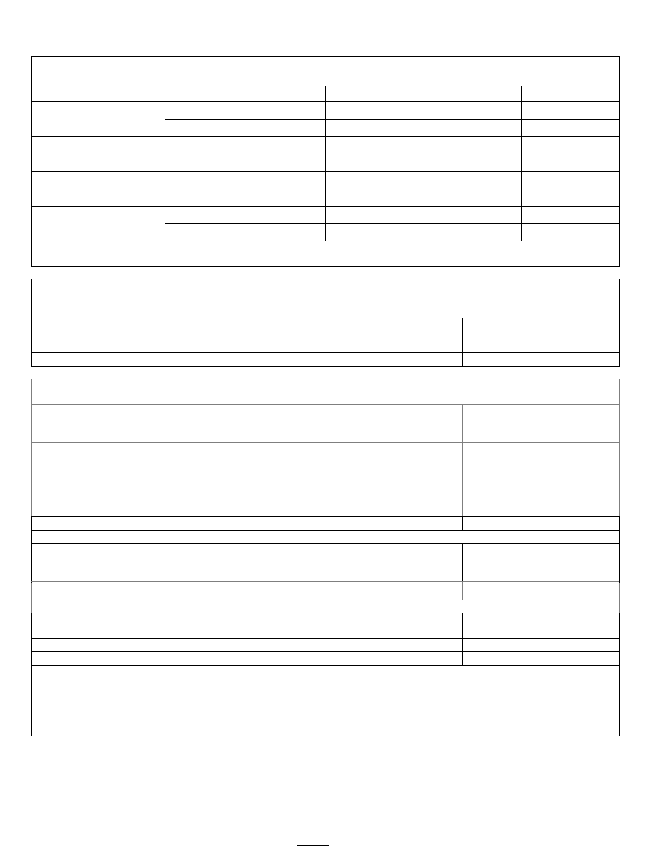
Enter Programming
-Turn the brewer OFF from the power switch.
-Turn the brewer ON. Brewer will boot up. After 10 seconds the STOP button will illuminate red
-Press and release the STOP button when it illuminates (red LED)
First stage of the Programming Menus will be in A-10 Batch Parameters. This is the most common programming.
Screens shown are for twin brewer. Single brewer will not have menu A4-A6.
There are seven menu groups-A-G . See the following pages for the batch parameter definitions and all settings for the brewer
TO ENTER PROGRAMMING
1-Turn brewer “OFF” from power switch
2-Turn power switch to “ON”
…Screen will initialize and then
display digital process notifications
3-After Initialization-Red “STOP” Lamp turns on
4-Quickly press “STOP” button.
When brewer is In PROGRAMMING MODE
-the screen will display:
|BATCH PRG|
|A (or B-H) |
-Illuminated LED indicates active keypad positions
See the following pages for batch parameter definitions
and all settings for the brewer
Turn power OFF
Turn power ON
Wait for red LED
And quickly press STOP
button on front touch pane
First screen will display
for PROGRAMMING-A
Scroll through main menu
topics by pressing “STOP”
button.
Note: Only the left side buttons of a two sided brewer are used for programming
Programing Menu Layout
A10 to A70
B10-B40
C10-C50
D10-D90
E10-E70
F10-F120
G1-G15
H10-H11
Batch Parameters
General Settings
Service Inputs
Service Outputs
Calibration
Service Menu
Counters
Exit and Save
|
|
|
|
|
|
|
|
A11
Brew Volume
B1
Tank Temperature
C1
LLC Probe
D1
Heater SSR
E1
Ready Temp. Offset
F1
Firmware Ver.
G1
Filter Used
H1
Save Changes
|
|
|
|
|
|
|
|
A12
Brew Time
B2
Brew at Temp
C2
Basket Sensor
D2
Fill Valve
E2
LLC Sensitivity
F2
Bootloader Ver.
G2
Filter Life
H2
EXIT?
|
|
|
|
|
|
|
A13
Prewet Percent
B4
Show Tank Temp
C4
Tank Temperature
D3
Lt Brew Valve
E3
Slow Flow Compensate
F3
Select Model
G3
Filter Reset
|
|
|
|
|
|
|
A14
Prewet Delay
B5
Units of Temp
C5
USB Drive
D4
Rt Brew Valve
E4
Lt Brew Flow
F4
Option Bypass
G4
Counter Reset
|
|
|
|
|
|
|
A15
Bypass Percent
B6
Units of Volume
C6
Keyboard Test
D5
Lt Bypass Valve
E5
Rt Brew Flow
F5
Option BB Lock
G5
Choose Counter
|
|
|
|
|
|
A16
Drip Delay
B7
Customer Name
D6
Rt Bypass Valve
E6
Lt Bypass Flow
F8
Backup to USB
G10
Brewer Volume [T]
|
|
|
|
|
|
A20
Batch (2) Enabled
B8
Customers Name
D7
Lt Basket Lock
E7
Rt Bypass Flow
F9
Restore from USB
G11
Brewer Volume
|
|
|
|
|
A21
Brew Volume
B9
Demo Mode
D8
Rt BasketLock
F10
Restore Defaults
G12
LT Brews[T]
|
|
|
|
|
A22
Brew Time
B10
Eco Mode
D12
LCD Brightness %
F11
Error Log
G13
LT Brews
|
|
|
|
|
A23
Prewet Percent
B11
Eco Idle Time
D13
LED Brightness %
F12
Erase Error Log
G14
Rt Brews [T]
|
|
|
|
A24
Prewet Delay
B12
Eco Idle Temp
F13
Service Phone#
G15
Rt Brews
|
|
|
A25
Bypass Percent
B13
Water Filter
F14
Override Lt BBS
See page 12
|
|
A26
Drip Delay
F15
Override Rt BBS
|
|
A30
Batch (3) Enabled
F16
Override Lt BBL
|
|
A90
Copy Batch
F17
Override Rt BBL
|
A91
Copy Batch: From
|
A92
PASTE: To
Top and middle batches are permanent SEE BOX on the following page for all “A” menus
STOP BUTTON
On/OFF
switch
located lower
right on back
Go to fetco.com for the latest versions of all information Page 7 User Guide & Operator instructions P213 CBS-1250 Pluse0 October 2024
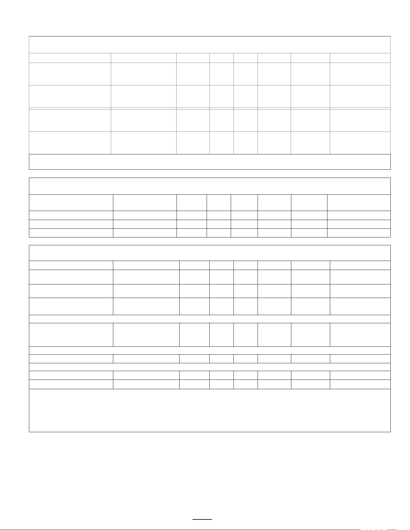
The Brew Sequence
First screen shows top
left brew position
being activated …
Right side is in
“READY-MODE”
during brew, and can
be accessed for
brewing
STOP brew lamp
activates and top left
button will pulsate.
All other buttons on the
left side extinguish.
Count down timer
activates beginning
5:30 for Batch 1
(5:00 for Batch 2)
The brewing cycle
completes in four minutes.
Stop button extinguishes
and drip out starts at 1:30
minutes.
Do not remove brew basket
during this part of the cycle.
Brewer returns to “ready to
brew” (screen one) after drip
out completes
RECIPE Location map
Viewing and changing settings for the brew
recipes is from the “A” screens with the controls in
PROGRAMMING.
The uppermost button positions are permanent
and will not display programming step A_0. The
table above shows in position A20 that a button
position can be made active or inactive.
Position A1 does not display this step
DISPLAY
DISPLAY
STOP
STOP
BATCH A1
(permanent)
BATCH A4
(permanent)
BATCH A2
(enabled by factory)
BATCH A5
(
enabled by factory)
BATCH A3
(disabled by factory)
BATCH A6
(
disabled by factory)
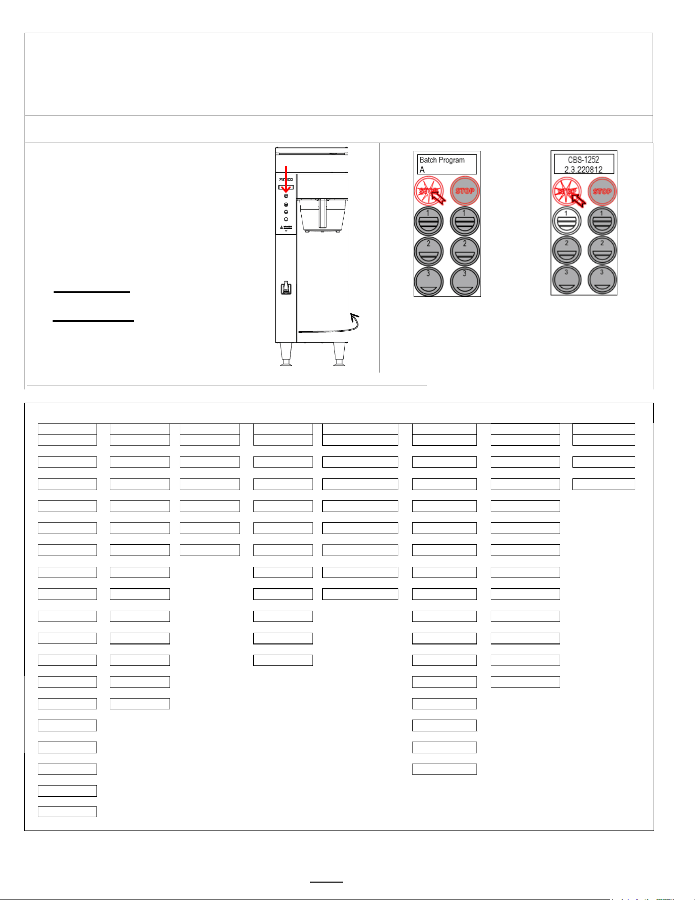
The “A” menu is the most accessed menu. It is for programming the batch volumes, setting brewing parameters,
enabling or disabling brew buttons. The “A” menu moves through the six positions(CBS-1252-) or three
positions(CBS-1251+) by entering the menu and pressing the left stop button. (only the left side is active for
programming the CBS-1252+)
The A menus [A1-3 or A1-6] correspond to batch buttons [3 or 6] on the touch panel
Access the A menus to PROGRAM & make changes to individual menu recipes. Menu settings can be copied
Menu positions A1 and A4 [top position] are permanent. Menus A2, A3, A5, A6 can be removed by operator if desired
A1 is top left A4 is top right. A1 & A4 are the only permanent positions and are factory set at 1.5gallons. Both are adjustable.
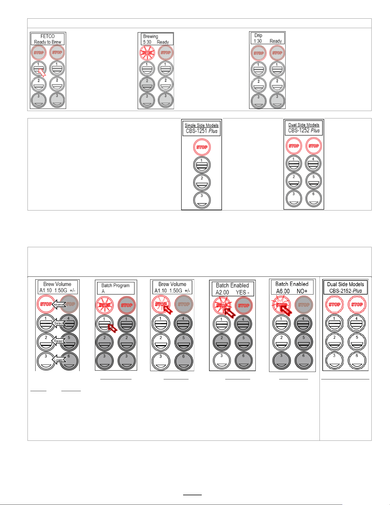
STOP-advances to the next
menu programming position
(A1 to A9 then to A,B,C,D…)
BUTTON #1-selects
program items in the menu
BUTTONS 3 & 4 raise and
lower the selection in the
menu
Pressing the STOP button
advances the next screen A20
A PRG screen
Press button 1 to go into to
the A menu access screens.
Continue pressing button #1
to enter programming for A1
A11 screen
A11 sets the top left side brew
button programming. Access
brewing parameters by pressing
button #1.
(Brew Volume, Time, Prewet &
Drip Delay)
A20 screen
Press STOP to
scroll through the remaining (3
to 6) “A” menus. Make any
changes as required
A6.00 screen
Scroll to remaining A10-to
A60 programming keys.
Changes will be lost
unless they are saved in
the programming routine.
See SAVE & EXIT in
previous table
Single&Twin Brewers
Position of batch buttons
for CBS-1252+
The CBS-1251+ single
position brewer has one
row of buttons

Go to fetco.com for the latest versions of all information Page 8 User Guide & Operator instructions P213 CBS-1250 Pluse0 October 2024
A Program
Menu Features: Batch Parameters
The settings below are shown for the top batch on a single brewer top left button on a twin brewer.
See how to access all A menus on the previous page. Below are the brew settings for default A1 & A2 batches
POSITION Program Items Factory set Default
Programming Range
Increments
Notes
A1.10 Batch Volume
1.5 gal
6.8 liters
0.51 to 2.00 gal
1.93 to 7.57L
0.01G
0.05L
A1.10
Batch Volume
CBS-2153 only
2 gallons
9.1 liters
0.51 to 2.66 gal
1.93 to 10.1L
0.01G
0.05L
A1.20 Brew Time 5:00 minutes 2:00 – 12:00 0.30
Default total brew time is 6:30
minutes
A1.30 Prewet Perc. 0% 0.00 – 25.0% 1%
Percentage of total brew
volume
A1.40
Prewet Delay
(Pause after prewet
completes)
0% [1:00 Min] [0:10 – 5:00] 1:00 min
The time between prewetting
and start of brew cycle.
This feature appears ONLY
if Prewet >0:00
A1.50 Bypass Percent
CBS-1251:10%
CBS-1252/3:15%
0% – 40% 1%
Diverts brewing water from
brew process
A1.60
This is a
Safety
Feature
Drip Delay 1:30 mm:ss 0:30 – 6:00 Min.
Time that brew basket remains
locked during final drip-out
Drip delay remains “ON” for
1:30 minutes if STOP is
pressed during brew†
A2.00
BATCH
ENABLED
YES
(Active)
Middle and Bottom
batches A2,3,5,6
Batch
on or off
Batches may be individually
enabled, rewritten or
deactivated
A2.10 Batch Volume
1.5 gal
6.8 liters
0.51 to 2.00 gal
1.93 to 7.57L
0.01G
0.05L
A2.10
Batch Volume
CBS-2153 only
2 gallons
9.1 liters
0.51 to 2.66 gal
1.93 to 10.1L
0.01G
0.05L
A2.20 Brew Time 4.00 minutes 2:00 – 12:00 0.30
Default total brew time is 5:30
minutes
A2.30 Prewet Perc. 0% 0.00 – 25.0% 1%
Percentage of total brew
volume
A2.40
Prewet Delay
(Brew pause after
prewet completes)
0% [1:00 Min] [0:10 – 5:00] 1:00 min
The time between prewetting
and start of brew cycle.
This feature appears ONLY
if Prewet >0:00
A2.50 Bypass Percent
CBS-1251:0%
CBS-1252&3: 0%
0% – 40% 1%
Diverts brewing water from
brew process
A2.60
This is a
Safety
Feature
Drip Delay 1:30 mm:ss 0:30 – 6:00 Min.
Time that brew basket remains
locked during final drip-out
Drip delay remains “ON” for
1:30 minutes if STOP is
pressed during brew†
A30
Batch Enabled
A30 YES -
NO +
NO-inactive
(defaults to recipe
A20 if activated)
Middle and Bottom
batches A2,A3
Batch
on or off
Batches may be individually
enabled, rewritten or
deactivated
A90
Batch
Copy
Copy From Batch A90 A90 1 (1-6)
A91
Copy To Batch?
A91
A91.1 (1-6)
PULSE BREW note. FETCO CBS-1200V+ brewers are factory programmed to pulse 2 cycles per minute brew time
Changing the brew time only will increase the pulses but will not change the volume of brew water delivered
.
Go to fetco.com for the latest versions of all information Page 9 User Guide & Operator instructions P213 CBS-1250 Pluse0 October 2024
B General
Brewer Operation Control Settings, Adjust Brew Flow Rate
POSITION Program Items Factory set Default Programming Range Increments Notes
B1 Tank Temp.
200°F-or-93° C
NOTE: Equipment is
Fahrenheit by default
77° to 97°C
170°F to 207°F
0.5°C
1.0°F
Chart to correct for
high altitude below
B2
Brew at Temp.
“YES”
ON/OFF
YES/NO
SEE NOTE BELOW
B4
Show Tank
Temperature
YES YES/NO
To display HW tank
temperature on screen
B5
Units of Measure
TEMPERATURE
F°-Fahrenheit Fahrenheit/Celsius C/F
NOTE: Overwrites
user settings (see page 9)
B6
Units of Measure
VOLUME
G-Gallons Gallons/Liters/Ounces Gal/L/Oz
NOTE: Overwrites
user settings (see page 9)
B7 Customer Name Off NO or YES For name on screen
B8 Customer Name (only if above is “ON) Scroll with batch keys A-Z;a-z;0-9 16 characters total
B9 Demo Mode DEMO ON/OFF
Demonstrates the controls
for training. Disables all
components in demo mode
B10 Eco Mode On ON/OFF YES/NO
If Selected: Lowers hot
water tank temperature after
preset time of inactivity
B11 Eco Idle Time 1Hr 1-6 hours 1 hour
Time of inactivity to go into
ECO Mode
B12 Eco Idle Temp 170°F 158-176°F 1 degree
Temperature that hot water
tank is lowered to
B13 Water Filter OFF ON/OFF YES/NO
Water filter life is accessed
in G-Counters. This is user
set and will display indicator
to change water filter
Chart to correct for altitude for boiling point
in tank water temperature.
[ft] [m]
Suggested
Setting[°F]
Boiling
point[°F]
Suggested
Setting[°C]
Boiling
point [°C]
0
0
205
212.0
96
100.0
500
152
205
211.0
96
99.5
1000
305
200
210.1
93
98.9
2000
610
200
208.1
93
97.8
2500
762
200
207.2
93
97.3
3000
914
200
206.2
93
96.8
3500
1067
197
205.3
92
96.3
4000
1219
195
204.3
91
95.7
4500
1372
194
203.4
90
95.2
5000
1524
194
202.4
90
94.7
5500
1676
193
201.5
89
94.2
6000
1829
192
200.6
89
93.6
6500
1981
191
199.6
88
93.1
7000
2134
190
198.7
87
92.6
7500
2286
188
197.8
86
92.1
8000
2438
187
196.9
86
91.6
8500
2591
185
196.0
85
91.1
BREW AT TEMPERATURE DEFINITIONS
DEFAULT: BREW AT TEMP: “ON”
(FACTORY DEFAULT FOR BREWER)
“BREW at TEMP:
-Batch will not start if tank temperature
is below set point.
-Display will show “HEATING”
and hot water tank temperature
The “BREW START” entry buttons will not
illuminate until the hot water tank reaches the
selected temperature.
Controls allow both sides of dual brewer to
operate if one side has an ongoing brew
started and the second side brew is selected.
Notifications shown on screen:
TEXT: HEATINGTank above 87°C/189°F-
will
allow brew at low temperature.
Coffee flavor may be affected
TEXT: L. HEATTank above 77°C/170°F-
will allow brew at low temperature.
Coffee flavor will be noticeably affected
Hot water tank not
at brew temp
setpoint.
Tank temp
STOP is not lit
BREW START
buttons not lit.
and are disabled.
When hot water
tank temperature
is at setpoint.
Buttons will
illuminate and
“READY” will be
displayed
vv
vv
vv
HEATING
160°F
USER SELECTABLE OPTION: BREW AT TEMP: OFF
(Not recommended) Unit will operate at lower temperature
Allows brewing at any temperature above 77°C/170°F
Below 70°C/170°F The brewer will display “HEATING”
STOP
STOP

Go to fetco.com for the latest versions of all information Page 10 User Guide & Operator instructions P213 CBS-1250 Pluse0 October 2024
C Service Inputs
Brewer Sensors and Keypad
POSITION
Program Items Factory set Default Programming Range Increments Notes
C1
LLC Probe
continuity
Direct read
Tank water
resistance in TDS
≈850- LOW
≈1600-HIGH
Nominal values
C2
Brew Basket
Sensor
L-YES R-YES YES or NO
C4
Tank
Temperature
Direct read
Hot water tank
temperature
Actual values
C5
USB Drive
NO
(not in use)
C6 Keyboard Test Calibrate
Checks buttons
under membrane
cover
YES/NO
Follow directions on the
touch screen
D Service Outputs
Test Valves and Heaters; Set screen brightness
POSITION
Program Items
Factory set
Default
Programming
Range
Increments Notes
D1 Heater SSR Test
Press button 2 to
test (button 1
stops test)
Activates heater
Default is 10 sec..
Toggle +/-
OFF or ON
Energizes Heater(s)
WARNING!
Service use only.
D2 Fill Valve Test
Press button 2 to
test (button 1
stops test)
Activates valve
Default is 10 sec.
Toggle +/-
OFF or ON
Press To Test
D3
LT (left)
Brew Valve Test
(Press to test)
Activates valve
Default is 10 sec.
Toggle +/-
OFF or ON
Runs valve to verify flow.
NOTE: Have container
under brew basket.
D4
RT (right)
Brew Valve Test
(Press to test)
Activates valve
Default is 10 sec.
Toggle +/-
OFF or ON
Runs valve to verify flow.
NOTE: Have container
under brew basket.
D5
LT (left)
Bypass Valve Test
(Press to test)
Activates valve
Default is 10 sec.
Toggle +/-
OFF or ON
Runs valve to verify flow.
NOTE: Have container
under brew basket.
D6
RT (right)
Brew Valve Test
(Press to test)
Activates valve
Default is 10 sec.
Toggle +/-
OFF or ON
Runs valve to verify flow.
NOTE: Have container
under brew basket.
D7
LT (left)
Brew Basket Lock Test
(Press to test)
Activates Brew
Basket Lock
Toggle +/-
OFF or ON
Press To Test
D8
RT (right)
Brew Basket Lock Test
(Press to test)
Activates Brew
Basket Lock
Toggle +/-
OFF or ON
Press To Test
Single series displays right side only Left Valve display is only for twin side brewer.
D12 LCD Brightness Brightness=90% 20-100% 5%
Adjust LCD screen
brightness only-Not for
LEDs under buttons
D13 LED Brightness Brightness=60% 20-100% 5%
Adjust LED button
brightness only-Not for
the screen display LCD
Go to fetco.com for the latest versions of all information Page 11 User Guide & Operator instructions P213 CBS-1250 Pluse0 October 2024
E Calibration
Brewer Sensors and Keypad
POSITION
Program Items
Factory set
Default
Programming
Range
Increments Notes
E1 Ready Temp. Offset
-3°F
-2°C
-2° to -9°F
-1° to -5° C
1°F
1°C
Compensates output to measured
temperature
E2 LLC Sensitivity
NORMAL
(“NORMAL”
for most
water)
HIGH
(Biased for
reverse osmosis
water or very
pure water)
NORMAL
HIGH
Liquid level control sensitivity.
High,1300Ω is for reverse
osmosis water or very pure water.
E3
Slow flow rate
from supply
ON OFF/ON
Toggle +/-
YES or NO
Trims fill system for low supply or
Flojet use
E4 LT Brew Valve flow rate: 0.95G
0.80-1.09G
1.30-1.90Liter
0.01G
0.05L
Adjusts flow rate
E5 RT Brew Valve flow rate: 0.95G
0.80-1.09G
1.30-1.90Liter
0.01G
0.05L
Adjusts flow rate
E6 LT Bypass Valve flow rate:
0.38G
0.31-0.44G
0.80-1.09Liter
0.01G
0.05L
Adjusts flow rate
E7 RT Bypass Valve flow rate:
0.38G
0.31-0.44G
0.80-1.09Liter
0.01G
0.05L
Adjusts flow rate
E10
Automatic Calibration
Use this formula to compensate for minor discrepancies in actual volume versus programmed volume.
See “PROGRAM” E4 & E5 For valve settings and calibration. Factory set brew valve flow rates are in liter/min
Current setting is the flow from E4,E5, E6, E7
Default Brew Valve Flow Rate—CBS-1250 Brewers
See table above for factory set default flow rates
CBS-1250
Gallons/minute
Range
ACTUAL VOLUME
X
CURRENT
SETTING
=
NEW
SETTING
Left Brew Valve FR
0.95
0.80G to 1.09G
PROGRAMMED VOLUME
Right Brew Valve FR
0.95
0.80G to 1.09G
Use this formula to determine the correct setting
Set FR lower to increase volume; set higher to decrease volume.
NOTE
Check for these causes for the difference in the programmed value to the brewed value. These must be corrected first.
-CSD spray head is not in place. This will always result in an increased flow volume
-Flow related error codes 100, 101 - see page 15. Reduced water flow can cause reduced brew volume.
-Clogged or fouled inlet valve or improperly installed inlet valve. See page 20.
-Verify the screens that the brew time is correct, and the display is operating as the brew valve may be turning off.
-Lime scale. This can cause erratic and sometimes random under or over brew volumes. Brew valve can drip, be stuck
open or closed, or fail due to lime scale accumulation. Always correct lime scale faults before changing flow rate.
Changing the flow rate corrects the brew volume if it is different from the programmed value.
Flow rate of over and under dispensing is corrected in FLOW RATE Calibration Procedure (E10) on the previous page.
The flow rate calibration procedure is an internal program to test for and enter corrections for flow rate inconsistencies.
In the procedure: the equipment will dispense for 60 seconds. The quantity of brew water dispensed is carefully
measured and entered into the program. The software automatically corrects the flow rate based on the difference of the
actual results to the stored values.
The procedure requires a calibrated 1½ gallon/6liter container. The flow must be very accurately measured. It will be
easiest to manage the readings if the brewer volume units are placed into ounces or liters for units of measure. [Go to
PROGRAM B6]. Units of measure in gallons require a calculation in fractional units of measure - which can be difficult.
TESTING SHOULD BE MADE WITH AN EMPTY BREW BASKET. NO FILTER PAPER. NO COFFEE OR TEA
Go to fetco.com for the latest versions of all information Page 12 User Guide & Operator instructions P213 CBS-1250 Pluse0 October 2024
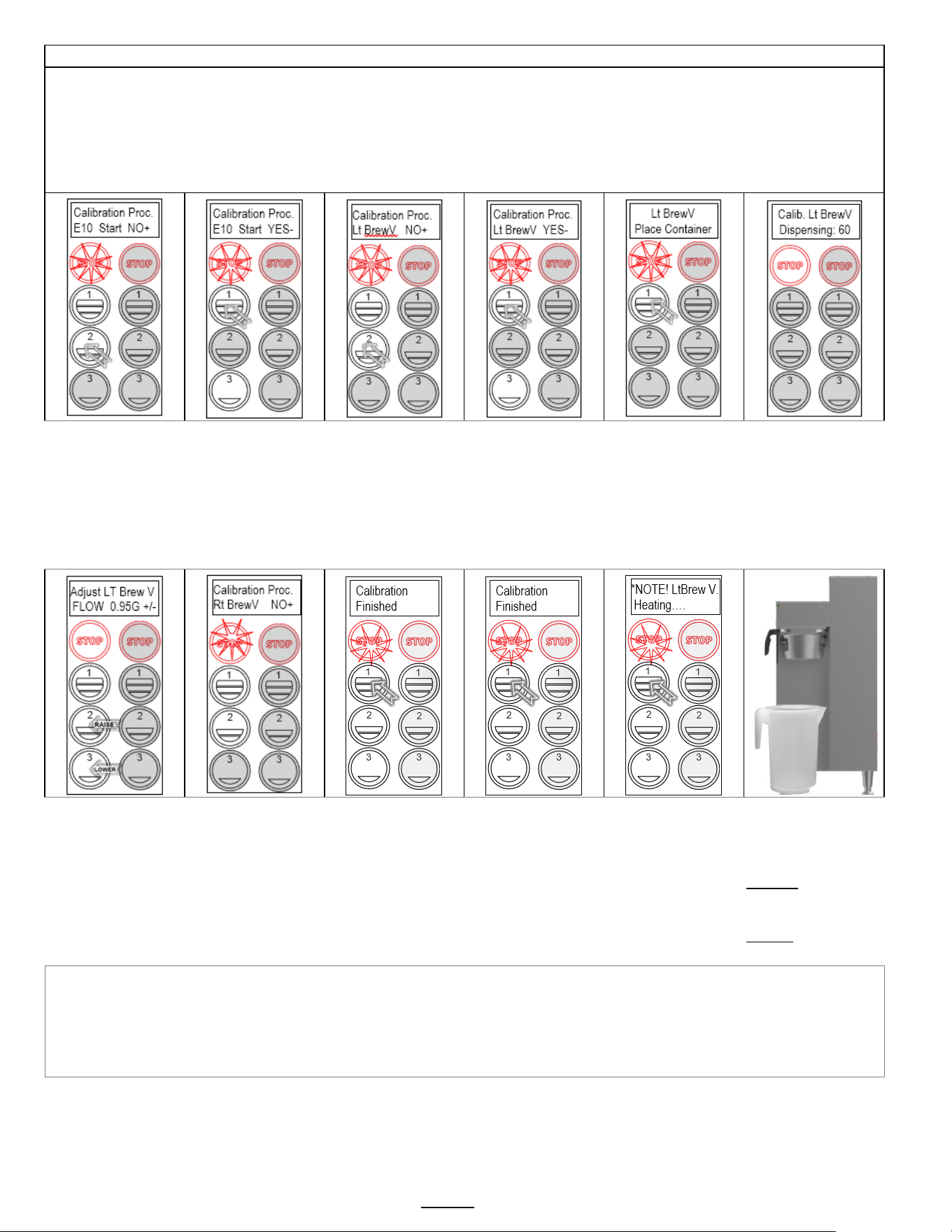
E10 Calibration Procedure - Automatic
Flow rate calibration is required when the volume dispensed differs significantly and consistently from the brewer setting.
This procedure automatically dispenses the selected valve brewer for 60 seconds.
Testing should be performed with an empty brew basket. No filter paper. No coffee or tea
This procedure tests the brew valve and bypass valves (right side or left side).
The quantity dispensed must be very accurately measured. Next: the dispensed quantity is entered into the brewer.
The brewer firmware contains algorithms that automatically adjust the valve flow rate to dispense correctly.
Opening screen
Press button #2 to
begin procedure
Confirm calibration
Press
button #1 to
proceed.
Proceed to next
screen to choose
which valve to test
Confirm which valve
(button1)
Lt BrewValve;
Rt BrewValve
Lt BypassValve;
Rt BypassValve by
toggling top button.
Next: Select & press
button 2 to proceed
Press button #1 to
Initiate left brew valve
calibration
Bottom button halts
procedure
Place calibrated 1½
gallon/6liter container
under left brew head.
(Lt BrewV)
Insert brew basket
Press button #1 to
begin testing
*See Note Below ↓
Brewer will dispense
for one minute.
Screen countdowns.
After drip out stops
…carefully and
accurately measure
the dispensed
quantity of hot water
Screen shows current
setting.
Enter the exact
quantity dispensed by
toggling two lower
buttons.
Press button #1 when
entered
Software then
automatically updates
the flow rate for the
left brew valve
The brewer proceeds
to the next valve.
Press button #1 to
scroll through valves
Rt BrewValve
Lt BypassValve
Rt BypassValve
Last selection is
Calibration Finished
Press STOP to
proceed to screen H
then: Save & Exit
If hot water tank is
not at correct
temperature.
Calibration holds until
temperature is
correct.
Brewer will continue
when at temperature
Measuring
Pitchers:
5 liter graduated
Bel-Art catalog
F28994-0000
10 liter graduated
Bel-Art catalog
F28995-0000
Default, factory set, flow rates
Left Brew Valve flow rate: 0.95G Right Brew Valve flow rate: 0.95G
Left Bypass Valve flow rate: 0.38G Right Bypass Valve flow rate: 0.38G
Go to fetco.com for the latest versions of all information Page 13 User Guide & Operator instructions P213 CBS-1250 Pluse0 October 2024
F Service Menu
Software & Code View and Settings
POSITION
Program Items
Factory set Default
Programming Range
Increments
Notes
F1
Display Firmware
2.2.210720
Displays current version
[6/2020]
F2
Display Bootloader
2.0.210317
Displays current version
[6/2020]
F3 Select Model
CBS-
1251;1252;1253
Will need reboot
Scroll to brewer
model Save & Exit
CBS-1221
CBS-1251, CBS-1252
CBS-1241, CBS-1242
CBS-1251, CBS-1252
CBS-1261, CBS-1262
MBS-1221, MBS-1251
TBS-1221, MBS-1222
NOTE: Overwrites all
user settings
(See below)
F4
Option Bypass
Yes
NO or YES
F5
Option BB Lock
Yes
NO or YES
F8 Backup to USB NO Follow prompts
Saves
settings
Insert blank USB
F9 Restore From USB
Applies settings from
USB
Insert USB
Will need reboot
F10 Restore Defaults NO NO/YES Reset to factory
F11 Error Log
Lists up to six
codes, in order
1: ; 2: ;3:;4: ;5: ;6:
1=Newest/6=Oldest
LAST six errors only
Newest=first
Oldest=last
See p14 Error Codes
Chart for references
F12 Erase Error Log NO +
Toggle +/-
YES or NO
FACTORY USE ONLY.
DO NOT RESET
F13
Service Phone #
Enter as needed
Set phone contact
F14 Override Lt BBS NO NO/YES
Toggle +/-
YES or NO
Disables brew basket
sensor
F15 Override Rt BBS NO NO/YES
Toggle +/-
YES or NO
Disables brew basket
sensor
F16 Override Lt BBL NO NO/YES
Toggle +/-
YES or NO
Disables brew basket
lock
F17 Override Rt BBL NO NO/YES
Toggle +/-
YES or NO
Disables brew basket
lock
Go to fetco.com for the latest versions of all information Page 14 User Guide & Operator instructions P213 CBS-1250 Pluse0 October 2024
Error Codes
(From SERVICE F11 and F12 – Page13)
DO NOT CLEAR ERROR CODES UNTIL ERROR IS IDENTIFIED AND CORRECTED
Contact factory or specialized personnel for error codes
Code
Description
Possible Cause
Corrective Action
001
Software error-error on start up or
corrupted software
Improper start-up or
shutdown
Restart, if still fault: reload software
002
Internal flash corrupted
internal data memory malfunction
Error found in cyclic
redundancy check CRC
Restart, if still fault: reload software
If not corrected: replace board
050
Short-circuit in temperature probe
Probe failure.
Replace probe.
051 Open temperature probe.
Bad probe connection, or
probe failure.
Check all connections. Replace probe if
necessary.
100
Initial Fill Error.
Initial fill time took longer than
expected after powering up.
Water supply flow rate is
too low, fill valve is stuck,
water line kinked or closed.
Reboot machine. If persists-investigate
cause of low flow rate. (Clogged water
filter, kinked line, stuck fill valve)
101
Error on refill-.
Tank did not refill within expected time.
Water supply flow rate to
hot water tank is too low, or
fill valve stuck or damaged
(SEE PAGE 19)
Check water supply line. Flow should be
20-75 psig, (138-517kPa) >1gal/3.8L/min
Investigate cause of low flow rate. If the
flow rate is in range-replace fill valve
200 Heating flatline-Tank is boiling
Heater is on, temperature is
not rising/dropping
High elevation correction. Bad heaters
or temperature probe or position
201
If the hot water tank heaters are turned
on during a heating cycle and tank
temperature is not increasing
according to software logic and the
tank temperature is below setpoint
1) Failure of SSR, high limit,
temperature probe, or
heating element.
2) Water being removed by
hot water faucet during
heating (control displays
“heating”)
1)Test and check SSRs, high limit
devices temperature probe. Check
heating elements with current clamp,
replace if necessary.
2)Advise staff to refrain from taking large
amounts of water from hot water tank,
especially during “heating”.
202 Heater Shorted or Stuck SSR
Heater is off and heating
SSR is stuck “ON”
Check ohms on heater (15-60Ω). SSR
may be stuck in ON mode-replace SSR.
255
Keyboard [HID] error
(Human Interface Device)
Usually from longer than 10
seconds’ contact. Or faulty
reassembly after service
Restart, if still fault: reload software. If
mechanical: replace module
NO
BSKT
Insert Brew Basket
Brew basket must be in
place
This is a
SAFETY FEATURE
Insert brew basket into brewer rails to
enable brewer
Go to fetco.com for the latest versions of all information Page 15 User Guide & Operator instructions P213 CBS-1250 Pluse0 October 2024
G Counters
Brewer Usage, Water Filter Usage, and Statistics
ROLE: [LT]=Permanent total for lifetime of machine; [R]=operator resettable; [User]=Input needed from operator
Position
Counter
Program items
Role
Information
Increments
Notes
G1-G4 are for water filter maintenance. All beverage equipment must use filtered water and filter cartridges must be monitored for quality
G4
A, S, B
Counter Reset
[User]
NO
Toggle +/- ,Y or N
Resets all resettable counters to zero
G5 A, S, B Choose Counter Factory set to BASIC
Basic=B
Advanced=A
Statistical=S
Stored brewer component activity..
See column 2, Counters, to identify where
counters are located.
G10-G15 Number of brews and volumes handled. Available in BASIC counter only (G5)
G10
B
Brewer Volume
[LT]
Dispensed volume Gallons/Liters Total of brews and hot water dispensed
G11
B
Brewer Volume
[R]
G12
B
Lt Brews
[LT]
Left side brew total
CBS-1252
Count Total brews-Left side (CBS-1252 only)
G13
B
Lt Brews
[R]
G14
B
Rt Brews
[LT]
Right side brew total
CBS-1251&CBS-1252
Count
Total brews-Right side
CBS-1251&CBS-1252
G15
B
Rt Brews
[R]
G20-G55 component use cycles and volumes handled. Available in ADVANCED counter only (G5)
G20
A
Fill Cycles
[LT]
Hot water tank refill
cycles
Count Cycles of hot water tank refill
G21
A
Fill Cycles
[R]
G22
A
Fill Volume
[LT]
Total volume of water
for all brews
Gallons/Liters Quantity of water for brews
G23
A
Fill Volume
[R]
G24
A
Lt Brew Cycles
[LT]
Left brew valve
operation on/off
Count
Totalized cycles of valve operation
(CBS-1252 only)
G25
A
Lt Brew Cycles
[R]
G26 A Lt Brew Volume [LT]
Left brew valve
flow through volume
Gallons/Liters
Totalized volume through left valve
(CBS-1252 only)
G27
A
Lt Brew Volume
[R]
G28
A
Rt Brew Cycles
[LT]
Right brew valve
operation on/off
Count
Totalized cycles of valve operation
CBS-1251&CBS-1252
G29
A
Rt Brew Cycles
[R]
G30
A
Rt Brew Volume
[LT]
Right brew valve
flow through volume
Gallons/Liters
Totalized volume through right valve
CBS-1251&CBS-1252
G31
A
Rt Brew Volume
[R]
G32
A
Lt Bypass Cycles
[LT]
Left bypass valve
operation on/off
Count
Totalized cycles of valve operation
(CBS-1252 only)
G33
A
Lt Bypass Cycles
[R]
G34
A
Lt Bypass Volume
[LT]
Left bypass valve
flow through volume
Gallons/Liters
Totalized volume through left valve
(CBS-1252 only)
G35
A
Lt Bypass Volume
[R]
G36
A
Rt Bypass Cycles
[LT]
Count Count
Totalized cycles of valve operation
CBS-1251&CBS-1252
G37
A
Rt Bypass Cycles
[R]
G38
A
Rt Bypass Volume
[LT]
Right bypass valve flow
through volume
Gallons/Liters
Totalized volume through right valve
CBS-1251&CBS-1252
G39
A
Rt Bypass Volume
[R]
G48
A
Lt BBL Cycles
[LT]
Left brew basket lock
flow through volume
Count
Totalized cycles of brew basket lock
operation (CBS-1252 only)
G49
A
Lt BBL Cycles
[R]
G50
A
Rt BBL Cycles
[LT]
Right brew basket lock
operation on/off
Count
Totalized cycles of brew basket lock
operation CBS-1251&CBS-1252
G51
A
Rt BBL Cycles
[R]
G52
A
Heater Cycles
[LT]
ON/OFF switching for
heating elements
Count Totalized cycles of heater switching
G53
A
Heater Cycles
[R]
G54
A
Heater On Time
[LT]
Total ON time for
heating element
Hour Totalized heater ON time in hours
G55
A
Heater On Time
[R]
G80-G91 See illustration below for batch button positions Available in STATISTICAL counter only (G5)
G80
S
Batch 10 Cycles
[LT]
Menu button selection
and activation count
Count
Total brews-left side top button
(CBS-1252 only)
G81
S
Batch 10 Cycles
[R]
G82
S
Batch 20 Cycles
[LT]
Menu button selection
and activation count
Count
Total brews-left side middle button
(CBS-1252 only)
G83
S
Batch 20 Cycles
[R]
G84
S
Batch 30 Cycles
[LT]
Menu button selection
and activation count
Count
Total brews-left side bottom button
(CBS-1252 only)
G85
S
Batch 30 Cycles
[R]
G86
S
Batch 40 Cycles
[LT]
Menu button selection
and activation count
Count
Total brews-right side top button
CBS-1251&CBS-1252
G87
S
Batch 40 Cycles
[R]
G88
S
Batch 50 Cycles
[LT]
Menu button selection
and activation count
Count
Total brews-right side middle button
CBS-1251&CBS-1252
G89
S
Batch 50 Cycles
[R]
G90
S
Batch 60 Cycles
[LT]
Menu button selection
and activation count
Count
Total brews-right side bottom button
CBS-1251&CBS-1252
G91
S
Batch 60 Cycles
[R]
Go to fetco.com for the latest versions of all information Page 16 User Guide & Operator instructions P213 CBS-1250 Pluse0 October 2024
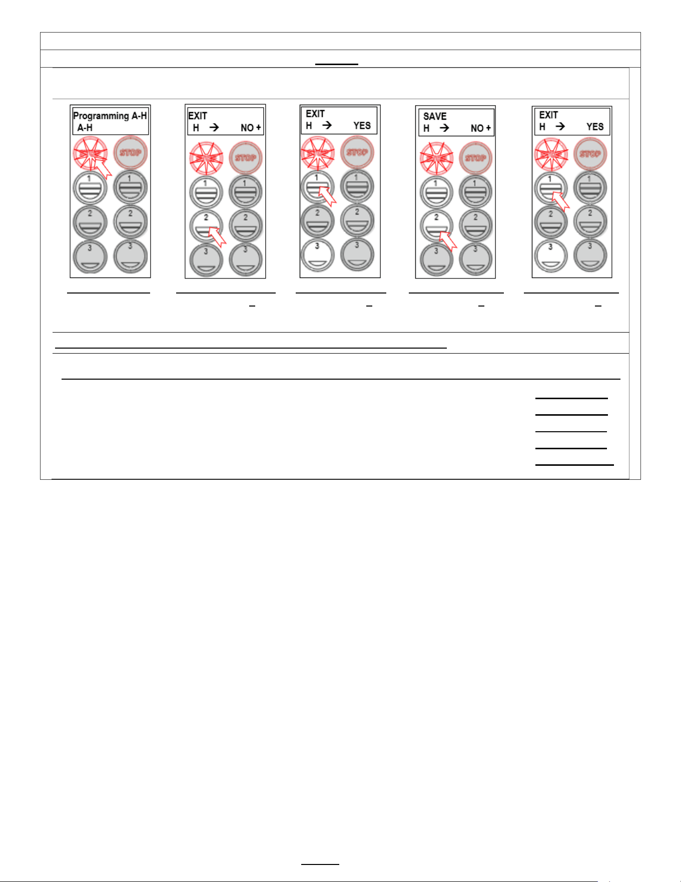
H Save & Exit
Saving changes and exiting PROGRAMMING
The brewer will save changes only from the “H” menu. DO NOT reboot brewer or toggle ON/OFF-exit as below.
TO EXIT PROGRAMMING & HOW TO SAVE CONTROL SETTING CHANGES
HOW TO SAVE CHANGES AND EXIT-The brewer is in PROGRAMMING mode.
From any screen-
Press STOP button
until the EXIT (“H”)
screen appears
From the “H” screen
Press button 2 to
toggle to the EXIT-
YES screen
From EXIT screen
Press button 1 to
toggle to the SAVE
screen
From SAVE screen
Press button 2, to
toggle to the SAVE-
YES screen
To SAVE and EXIT
Press button 1 to
SAVE your changes
and EXIT
Note: Only the left side buttons of a two sided brewer are used for programming
NOTE: User Settings will be erased and overwritten to factory default settings by the following five programming changes
1) When setting or changing units of display for the tank temperature (F Fahrenheit or C Celsius). (SETTING B4)
2) When setting or changing units of display for the volume (L, G gallons). (SETTING B5)
3) When setting brewer model The software sets equipment to brewer defaults (SETTING F3)
4) When loading from USB (Reprograms settings) (SETTING F9)
5) When restoring defaults (Reloads to defaults ) (SETTING E10)

Go to fetco.com for the latest versions of all information Page 17 User Guide & Operator instructions P213 CBS-1250 Pluse0 October 2024
Operator Training
Review the operating procedures with whoever will be using the brewer.
Pay particular attention to the following areas:
1. Always pre-heat the dispensers before the first use of each day by filling them halfway with hot water and letting
them stand for at least 5 minutes.
2. Do not remove the brew basket from a coffee brewer until it has stopped dripping.
3. Make sure the dispenser is empty before brewing into it.
4. Show how to attach covers, close, and or secure the dispensers for transporting.
5. Show the location and operation of the water shut off valve as well as the circuit breaker for the brewer.
6. Steam from the tank will form condensation in the vent tubes. This condensation will drip into and then out of the
brew baskets. Up to 1/4 cup/118cc discharging overnight is possible. Place an appropriate container under each
brew basket when not in use.
7. We recommend leaving the power to the brewer on overnight. The water tank is well insulated and very little
electricity is used to keep the tank hot. Leaving the brewer in the “ON” position will also avoid delays at the beginning
of shifts for the brewer to reach operating temperature.
Cleaning & Maintenance
After Each Brew:
1. Dispose of grounds and rinse brew basket.
2. Never strike a brew basket or hit it against a hard surface.
This will damage the brew cone, and may damage the brew basket support rails
3. Rinse dispensers before reuse.
Every Day:
1. Wash brew basket with hot sudsy water.
2. Pull CSD from the spray head, it is magnetically attached. Use gloves or a heavy towel.
Wash off any film and reattach. Use vinegar if limescale filming is present.
3. Clean dispensers with hot suds water and a brush, rinse and air dry.
4. Use only a soft cloth and hot suds on the outside to avoid scratches. Never use abrasives that will scratch surface.
Weekly
1. Use a commercial coffee dispenser cleaner such as URNEX™, TABZ™, DIP-IT™ or Squeak 'n Clean™.
2. Carefully Follow the instructions supplied with the cleaning product
3. Never use spray cleaners, solvent, solvent based cleaner or petroleum based polish anywhere on dispensers
Warning
1. Turn off power before any cleaning procedure, including wiping the exterior for appearance reasons.
2. Dry the exterior, especially the face panel, before turning on power.
3. Do not apply any type of spray cleaner on the face panel of this equipment.
4. Never use solvent or solvent-based cleaner or petroleum based polish anywhere on this equipment.
5. Dry the face of the touch pad before turning on power
6. Do not electrically energize this equipment or attempt operation without all covers in place and all screws fastened.
7. Unplug machine before disassembly or servicing.
Safety Notes
1. Professional installation is required. This appliance is manufactured only for commercial use
2. Operational requirements and maintenance for commercial cooking appliances differ from household appliances.
3. Operators must be trained in this equipment and must understand the use, maintenance and hazards.
4. Access to the service area is restricted to persons having safety/hygiene knowledge and practical experience of the
coffee brewer. This appliance must be installed in locations where it can be overseen by adult trained personnel.
5. Do not attempt to move hot beverage equipment once it is filled. Drain equipment before moving.
6. FETCO commercial coffee brewers prepare large amounts of coffee or tea in a single batch using very hot water
7. Commercial coffee brewers provide very hot water from the spray head, brew basket and faucet when it is pulled.
8. Coffee brewers may continue to dispense very hot water from the mechanically operated faucet after the electronic
touchpad is completely disabled by turning off the power switch on the lower back of the unit or unplugging the unit.
9. For safety, the brewer control locks the brew basket for 6.0 minutes after starting the brew.
10. Never attempt to defeat the factory set (default) time that the brew basket is locked in safety from start of brew.
Keep these instructions for training and future reference.

Go to fetco.com for the latest versions of all information Page 18 User Guide & Operator instructions P213 CBS-1250 Pluse0 October 2024
(For Qualified Service Technicians Only)
General:
1. If not installed correctly by qualified personnel, the brewer will not operate properly, and damage may result.
2. Utilize only qualified beverage equipment service technicians for service and installation.
3. Always have an empty dispenser under spray head of all coffee brewing equipment-including when at idle
4. Damages resulting from improper installation are not covered by the warranty and will void the warranty.
Below are the key points to consider before installation:
Electrical:
1. All CBS Series brewers require an electrical ground wire. Installation without grounding is dangerous.
2. Note Equipotentiality Terminal, if present,
(To identify the terminals which, when connected together, bring the various parts
of equipment or of a system to the same potential, not necessarily being the earth (ground) potential, e.g. for local bonding.)
3. Verify voltages, polarity, circuits, and circuit breaker access before attaching equipment.
4. Brewers in this series wire differently in regard to a neutral wire. Review the wire diagrams.
5. The electrical diagram is located in the User’s Guide and online at www.fetco.com.
6. Make sure of the tight grounding of the equipment is tight and use the external ground bolt.
7. The installation must comply with applicable federal, state, and local codes having jurisdiction at your location.
Check with your local inspectors to determine what codes will apply.
See wiring diagrams on pages 29-31 for connections
Plumbing:
1. North America: All installations must comply with applicable federal, state, or local plumbing codes.
2. All Others: The water and waste piping and connections shall comply with the International Plumbing Code,
International Code Council (ICC), or to the Uniform Plumbing Code (IAPMO).
3. Install a backflow prevention device. Most municipalities require a recognized backflow preventer
Usable on all hot beverage and cold beverage equipment is a WATTS® SD-2 or SD-3.
WATTS spring loaded double check valve models are accepted by most zoning authorities.
The check valve should be as close to the water supply inlet of the beverage equipment as possible
4. All beverage equipment must use a water filter. A finishing carbon filter is preferred
5. Install the filter unit after a water shutoff valve and in a position to facilitate filter replacement.
6. The water line and newly installed filter cartridge must be flushed thoroughly prior to connecting it to the brewer to
prevent debris from contaminating the machine
7. Verify that the water line will provide a flow rate of at least 1½ gpm/(5.7lpm) per minute and the water pressure is
between 20-75 psig (138-517kPa) before making any connections
8. Only use the supplied factory fitting to attach water supply line to brewer (shipped in brew basket)
9. The suppled fitting is a 3/8” flare/compression fitting for 1/4” supply line. Other adaptors may be substituted.
10. Hand tighten the factory fitting when connecting the stub on the brewer. This will reduce stress on the internal
connections and reduce the possibility of leaks developing after the install has been completed
Tank Drain
The water tank must be drained before maintenance procedures, and when the unit is to be relocated or shipped.
Drain is for service use only and must not be permanently connected. NOTE: Never plumb a water line to the drain.
1. Disconnect power and water to unit. DANGER: Ensure that all utility connections to the brewer are broken.
2. Move the unit near a sink or obtain a container large enough to hold four gallons of water.
Note: The CBS-1251 hot water tank when full holds 6.5 gallons; the CBS-1252 11.1 gallons.
3. Remove the front panel and tank cover and allow the tank to cool to a safe temperature
4. The tank drain line and clamp are located inside-under the hot water tank. Pinch the drain line clamp to close
5. Locate the fill valve against the back wall, using pliers, loosen the hose clamp and move it back over the tube.
Note Do not loosen the hose clamp to the bottom of the hot water tank
6. Crimp the tube an inch or two away from the drain plug to prevent water from flowing and pull it off the valve.
7. Pull the tube end out of the brewer and position over sink or bucket.
8. Release the crimped tube and hose clamp and allow the water to flow into the sink or container.
9. Reverse steps 4-8 when service is complete. Ensure pinch clamp is open and hose clamps are in place.
Brewer Hot Water Tank Capacity
OPEN
Leave open for use
PINCH SHUT
To drain tank & service brewer
AI!
CBS-1251 Single 6.5 gal 24.4 liter
CBS-1252 Twin 11.1 gal 42.1 liter
Go to fetco.com for the latest versions of all information Page 19 User Guide & Operator instructions P213 CBS-1250 Pluse0 October 2024
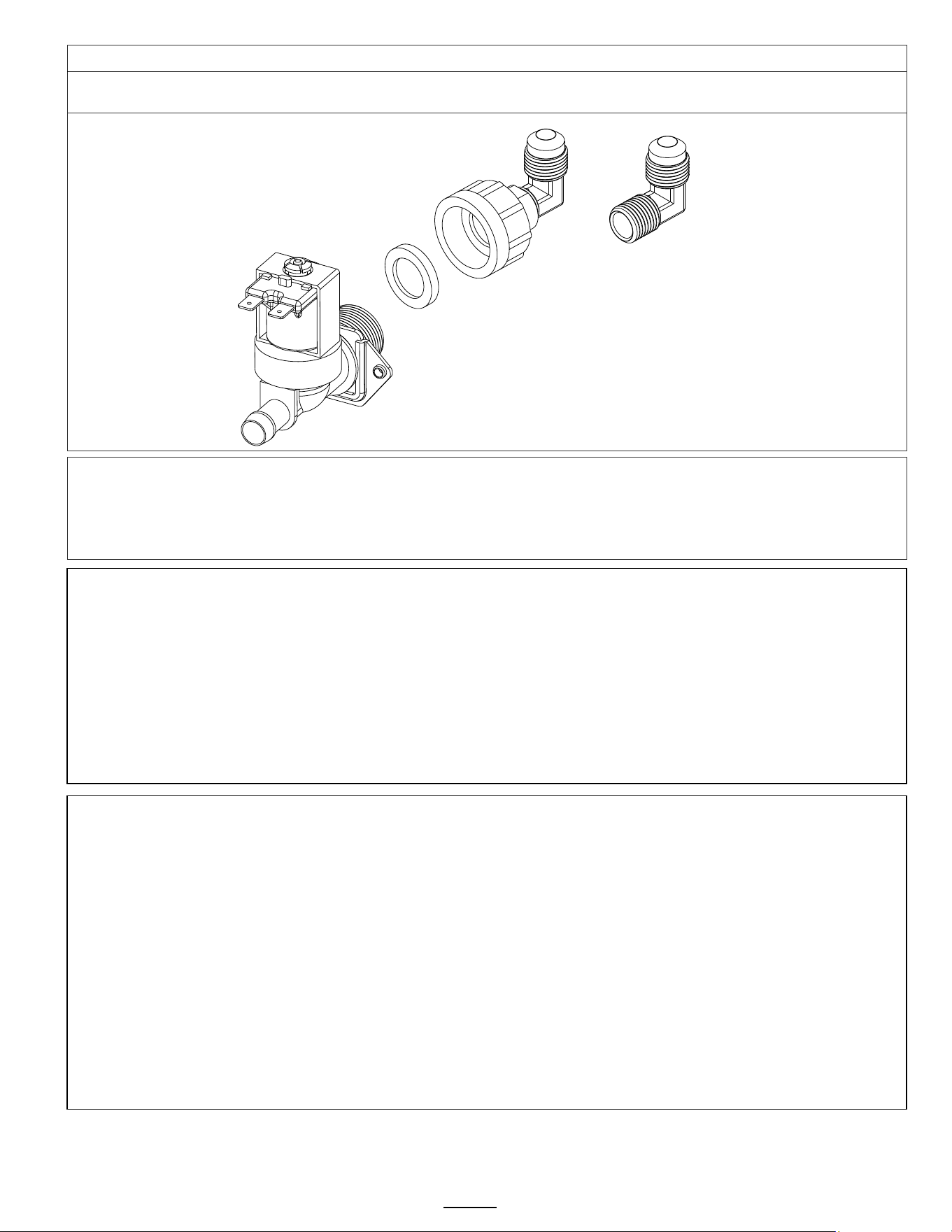
Brewer Setup
Attach water inlet adapter
Place rubber washer with screen in adapter. Hand tighten only-and 1/4 turn with wrench
Install the adapter on inlet valve first before attaching water line. Adapter is shipped in the brew basket
The valve threads are 3/4" BSP MALE THREAD and are not 3/4 garden hose fittings.
Use of any other connector to valve will damage the valve
DO NOT use USA dishwasher water adapter or USA washing machine adapter for this connection.
The threads on these USA adapters are unusable for the valve and will damage the valve
TO PREVENT DAMAGE AND INSURE PROPER EQUIPMENT OPERATION
The inlet valve thread is 3/4 INCH BSP (British Standard Pipe).
This valve is not a standard USA washing machine or dishwasher thread (¾” GHT)
-Use only the plumbing adaptor kit included with this equipment. Use the gasket included in adaptor kit
-Plumber’s tape is not recommended for the adapter to valve connection
-Hand tighten adapter on valve with gasket, then very lightly wrench 1/4 turn to set
-DO NOT SUBSTITUTE FITTINGS FOR CONNECTING TO WATER SUPPLY
Damage to inlet valve from improper installation will void the warranty
NOTE: DO NOT TANK PLUMB DRAIN. DRAIN IS FOR SERVICE AND MAINTENANCE.
Notes on Modifying Equipment
!!TO PREVENT SERIOUS DAMAGE TO THE EQUIPMENT, PROPERTY AND INJURY OR DEATH!!
-Do not modify any part of the internal water handling system of any FETCO product.
-Do not modify any part of the electrical system of this equipment including any part of a low voltage DC bus, if present.
-Use only FETCO supplied parts and service methods advised by FETCO. Never substitute with any non-FETCO part.
Only one electrical modification is allowed at the terminal block when installing the brewer to the power utility.
This modification is either to convert the equipment from three-phase to single-phase or, in certain models, to change
from the factory-installed 120VAC cord and plug to a 240VAC input.
These specific models are identified by the SKU number on the product label. FETCO offers clear and explicit
instructions for modifying wiring from the utility connection, adjusting terminal block wiring, and installing any jumper
wires for these models.
Any plumbing or electrical connection or modification must be carried out by a licensed technician.
FETCO
Inlet valve
Rubber washer
with screen
(Included with
adapter)
Inlet valve
adapter
90 degree 3/8” flare fitting
This may be removed
and replaced with a 3/8”
compression fitting or
other connection.
Fitting to base is ¼” NPT
Use thread sealing
plumber tape or sealant
paste on threads
3/8”
flare fitting
¼” fnpt base
Go to fetco.com for the latest versions of all information Page 20 User Guide & Operator instructions P213 CBS-1250 Pluse0 October 2024
Installation safety and hygiene directions-For International and CE equipment
1. Access to the service area is restricted to persons having safety/hygiene knowledge and practical experience of
the coffee brewer. This appliance must be installed in locations where it can be overseen by trained personnel.
2. For proper operation, this appliance must be installed indoors where the temperature is between 10°C/50°F to
35°C/95°F. Drain and remove all liquid from equipment and lines if exposed to freezing temperatures.
3. All commercial cooking equipment, including this unit, is not intended for use by children or persons with reduced
physical, sensory, or mental capabilities. Ensure proper supervision of children and keep them away from the unit.
4. Children should be supervised to ensure that they do not play around hot beverage equipment.
5. This unit must be installed and serviced by qualified personnel only.
6. Installation must conform to all local electrical and plumbing codes. Installation by unqualified personnel will void
the unit warranty and may lead to electric shock or burn, as well as damage to unit and/or its surroundings.
7. If the power cord requires repair or replacement-it must be performed by the manufacturer or authorized service
personnel with the specified cord only from the manufacturer in order to avoid a hazard.
8. Review the dimensions for the unit and verify that it will fit properly in the space intended for it. Verify that the
counter or table will support the total weight of the brewer and dispensers when filled (See: Technical Data).
9. Place the brewer on the counter or stand. When the brewer is in position, level it front to back as well as side-to-
side by adjusting the legs.
10. Brewers will need a sturdy supported surface for operation. Do not move brewers when filled.
11. Do not tilt appliance more than 10° to insure safe operation.
12. Unit is for protected indoor use only. Do not steam clean or use excessive water on unit.
13. This unit is not “jet-proof” construction. Do not pressure wash or use jet spray to clean this unit.
14. The unit is not waterproof-do not submerge or saturate with water.
Equipment exposed to flood and contaminated must not be used due to electrical and food safety.
Do not operate if unit has been submerged or saturated with
water.
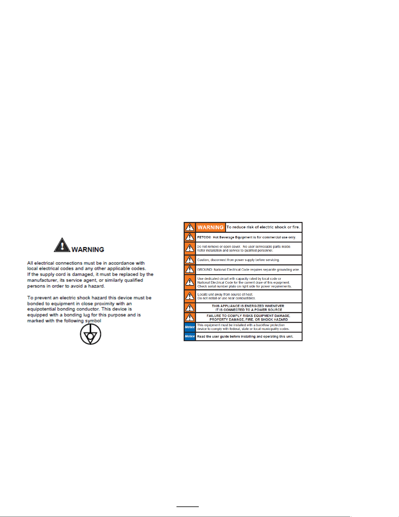
Labels and
warnings for hot
beverage
equipment
For BACK PANEL
of equipment
(1046.00035.00)
Go to fetco.com for the latest versions of all information Page 21 User Guide & Operator instructions P213 CBS-1250 Pluse0 October 2024
Winterizing equipment
FETCO® equipment should not be exposed to below freezing conditions. Water tank and lines may crack from expansion
of freezing water. Commercial kitchen equipment is for indoor use unless rated as IP44 (NEMA-3 equivalent)
Other problems
Live flexible gaskets, tubes and membranes are damaged from freeze/thaw cycles. These elastic materials are
compounded for high temperatures and steam contact.
To store or move idle equipment during freezing weather
Have common tools including standard screwdriver set, adjustable wrench, long nose pliers, caps and plugs for
disconnected plumbing lines. Also have a wet/dry vacuum set up for wet pickup, flashlight, lock out tags and permanent
marking pen.
Perform all brewer and dispenser maintenance prior to shut down.
Sanitize dispensers, drain & dry and if possible store upside down or on sides with lids propped open.
Turn off power. Disconnect brewer from water supply then cap and plug the connectors. Unplug the brewer or disconnect
the power.
Open the brewer to access the tank. Open hot water tank cover and drain hot water tank.
After tank is drained, vacuum any moisture out of the hot water tank and brew lines with a new or sanitized hose and tool.
Vacuum the hot water service line through the open faucet. Attempt to remove all moisture. Purging with pressurized air is
not recommended
At the factory -when preparing for shipping to the customer vacuuming and drying is performed after calibration on a warm
brewer. The warm surfaces help dry out moisture.
Inoperative equipment should be tagged. This will assist while it is inactive and at restart.
Unscrew the legs from the bottom if moving equipment
NOTE: Do not use any antifreeze or food safe antifreeze, usually propylene glycol, in this equipment
Descaling equipment
Commercial coffee brewers do not require routine descaling. The water supply mineral content range should be 100-
150TDS. This will not contribute to lime scale in normal use.
For water with high mineral content: use a commercial reverse osmosis system to provide the best coffee and tea
extraction and provide protection to the equipment from limescale.
A limescale ameliorating water filter, BestMax® or similar, will help control lime formation and protect the brewer if
reverse osmosis is not available .
Should the unit need professional descaling: contact the factory for guidance: techsupport@fetco.com
NOTE: Never use muriatic acid, hydrochloric acid, hydrogen chloride solution or descaling compounds containing
chlorine. Severe and permanent damage to the metallic components will result and will void the warranty.
Table of Authorities CBS-1250 Plus
CBS-1251
CBS-1252
CBS-1253
Item Number
Tank Assembly
Wiring Diagram
Item Number
Tank Assembly
Wiring Diagram
Item Number
Tank Assembly
Wiring Diagram
E1251US-1B230-PM110
1104.00168.00
1401.00196.10
E1252US-UB250-PM110
1104.00163.00
1401.00179.10
E1253US-UB250-PM110
1104.00163.00
1401.00179.10
E1251US-1B230-PM100
1104.00168.00
1401.00196.10
E1252US-UB250-MM110
1104.00163.00
1401.00179.10
E1253US-UB250-MM110
1104.00163.00
1401.00179.10
E1251US-1B230-MM110
1104.00168.00
1401.00196.10
E1252US-UB230-PM110
1104.00160.00
1401.00179.10
E1253US-UB230-PM110
1104.00160.00
1401.00179.10
E1251NM-1B230-PM110
1104.00168.00
1401.00196.10
E1252US-UB230-MM110
1104.00160.00
1401.00179.10
E1253US-UB230-MM110
1104.00160.00
1401.00179.10
E1251KS-1B230-PM110
1104.00168.00
1401.00196.10
E1252NM-UB250-PM110
1104.00163.00
1401.00179.10
E1253NM-UB250-PM110
1104.00163.00
1401.00179.10
E1251IN-1B230-PM110
1104.00168.00
1401.00196.10
E1252NM-1B250-PM110
1104.00164.00
1401.00199.10
E1253NM-1B250-PM110
1104.00164.00
1401.00179.10
E1251IN-1B150-PM110
1104.00166.00
1401.00196.10
E1252KS-3C330-PM110
1104.00160.00
1401.00191.10
E1253IN-3C350-PM110
1104.00163.00
1401.00191.10
E1251IN-1B140-PM110
1104.00165.00
1401.00196.10
E1252IN-3C350-PM110
1104.00163.00
1401.00191.10
E1253IN-3C340-PM110
1104.00162.00
1401.00191.10
E1251CE-1B230-PM110
1104.00168.00
1401.00193.10
E1252IN-3C340-PM110
1104.00162.00
1401.00191.10
E1253IN-3C330-PM110
1104.00160.00
1401.00191.10
E1251CE-1B130-MM005
1104.00210.00
1401.00192.10
E1252IN-3C330-PM110
1104.00160.00
1401.00191.10
E1253IN-1B250-PM110
1104.00164.00
1401.00199.10
E1251BR-1B230-PM110
1104.00168.00
1401.00196.10
E1252IN-1B250-PM110
1104.00164.00
1401.00199.10
E1253IN-1B230-PM110
1104.00161.00
1401.00199.10
E1252IN-1B230-PM110
1104.00161.00
1401.00199.10
E1253BR-1B250-PM110
1104.00164.00
1401.00199.10
E1252CE-3C350-PM110
1104.00163.00
1401.00191.10
E1252CE-3C330-PM110
1104.00160.00
1401.00191.10
E1252BR-1B250-PM110
1104.00164.00
1401.00199.10
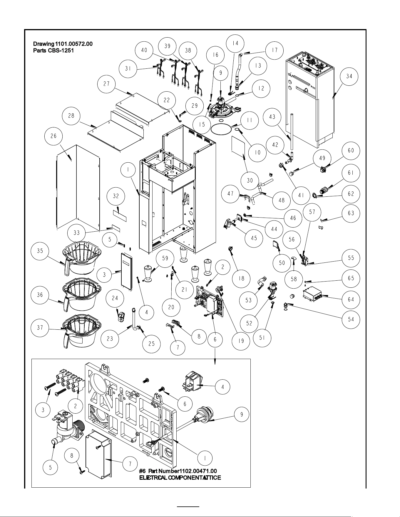
Go to fetco.com for the latest versions of all information Page 22 User Guide & Operator instructions P213 CBS-1250 Pluse0 October 2024
Parts Diagram CBS-1251

Go to fetco.com for the latest versions of all information Page 23 User Guide & Operator instructions P213 CBS-1250 Pluse0 October 2024
Ref
Qty
Part Number
Description Drawing 1101.00572.00, CBS-1251
1
1
1111.00100.00
WELDMENT BODY, CBS-2251
2
6
1084.00051.00.
NUT, HEX LOCKWASHER, #8-32, 18-8 ST. STL
3
1
1102.00480.00
FRONT PANEL ASSY, SINGLE, PLUS SERIES
4
2
1082.00029.00
SCREW, #6 X 3/8 LG, TRUSS HD PHIL, SHEET MTL
5
2
1082.00058.00
SCREW, # 8-32 X 5/8, FLAT HD, PH, 18-8 SS
6
1
1102.00471.00
ELECTRICAL COMPONENT LATTICE, NEXT GEN XV+
6 REF
1
Reference
ELECTRICAL COMPONENT LATTICE, NEXT GEN XV+
6-1
1
1023.00350.00
ELECTRICAL MOUNTING LATTICE, COMMON
6-2
1
1052.00023.00
EUROSTRIP HE16 TERM. BLOCK, 4 POLE, 63 AMP, 18-8 AWG
6-3
2
1082.00056.00
SCREW, # 8-16 x 1" PAN HD PHIL, THREAD FORMING, FOR PLASTICS, 18-8 SS
6-4
2
1058.00024.00
SWITCH, POWER, DOUBLE POLE, 16A, 125/250 VAC
6-5
1
1057.00043.00
SOLENOID VALVE, 5.5L/min, 180 DEG, 24VDC
6-6
2
1082.00010.00
SCREW, PAN HD. PHIL. MACH., M4x10 ZINC-PLATED
6-7
1
1052.00059.00
POWER SUPPLY, 90-264VAC/24VDC, 2.25A
6-8
2
1082.00020.00
SCREW, #6 X 5/8, TRUSS HD PHIL, SHEET MTL
6-9
2
1058.00055.00
USB CONNECTOR
7
1
1097.00171.00
ADHESIVE, RGB LED BAR
8
1
1023.00390.00
LENS, LIGHT BAR, BLACK
9
1
1102.00450.00
QUICK CONNECT SRAYHEAD ASSEMBLY, BASIC [See Page 32 for expanded drawing]
10
2
1024.00107.00
O-RING, 1 3/16" OD X 1 1/16" ID X 1/16" TH, BYPASS SEAL
11
1
1024.00108.00
O-RING, 5 11/16"OD X 5 1/2" ID X 3/32" TH, BREW SEAL
12
2
1024.00106.00
O-RING, 13/16"OD X 11/16"ID X 1/16" TH, FOR QUICK CONNECT
13
1
1023.00343.00
VENT INSERT, QUICK CONNECT
14
2
1023.00342.00
QUICK CONNECT CLIP
15
10
1083.00010.00
WASHER, #10 SCREW W/NEOPRENE-BONDED SEAL
16
10
1084.00006.00
NUT, 8-32 18-8 HEX MACHINE SCREW
17
1
1024.00098.00
VENT TUBE, CBS- EXTRACTOR SERIES
18
1
1086.00004.00
BUSHING, SNAP, 1" MOUNTING HOLE
19
1
1102.00243.00
ADAPTER ASSY, 3/4" BSP x 1/4" NPT x 3/8" TUBE
20
2
1065.00009.00
GROUND LUG CONNECTOR, 14-2 AWG, ALUMINUM
21
1
1044.00012.00
LABEL GROUND, CE
22
12
1084.00011.00
NUT, CLIP ON (J-NUT), #6-32, 22-20 GA., BLK-PH FINISH
23
1
1025.00058.00
TUBE, 9/16"OD X 5/16"ID X 25.00"LG
24
1
1086.00009.00
CLAMP, 3/4" MAX TUBE OD FLOW CONTROL
25
4
1086.00003.00
UNICLAMP, 15.9 HOSE OD CLAMP
26
1
1112.00529.00
WELDMENT FRONT COVER, CBS-2250
27
1
1001.00402.00
COVER TOP, CBS-2251
28
1
1001.00403.00
COVER, UPPER BASE, CBS-2251
29
12
1082.00017.00
SCREW, TRUSS HD. PHIL. MACHINE, # 6-32 X 1/2 LG.
30
1
1046.00035.00
LABEL, WARNING "TO REDUCE RISK OF ELECTRIC SHOCK OR FIRE"
31
1
1402.00097.10
WIRE HARNESS, CBS-1240/50, LOW AMP, UNIVERSAL
32
1
1046.00003.00
LABEL, CSD WARNING, 1.5" X 5.0"
33
1
1041.00033.00
BLACK EXTRACTOR PLUS LABEL, LASER ENGRAVED
34
1
1104.00165.00
TANK ASSEMBLY, CBS-2251, 1 X 4KW/240VAC [See additional pages for expanded drawing]
34
1
1104.00166.00
TANK ASSEMBLY, CBS-2251, 1 X 5KW/240VAC
34
1
1104.00167.00
TANK ASSEMBLY, CBS-2251, 2 X 2.3KW/240VAC
34
1
1104.00168.00
TANK ASSEMBLY, CBS-2251, 2 X 3KW/240VAC
35
1
B015280BN2BK
BREW BASKET ASSY, 16" X 6", 0.280" DIA HOLE, BROWN PLUG
36
1
B001280B1BB
ASSY, 16" X 6", 0.280 DIA HOLE, BLACK
37
1
B002280B1BB
ASSY, 16" X 6", 0.280" DIA HOLE, BLACK-with clips (OPTIONAL)
38
1
1402.00037.10
HARNESS HIGH AMP, CBS-2232/42/51, UL
39
1
1402.00039.10
HARNESS HIGH AMP, CBS-2231/41/51, UL
40
1
1402.00121.10
WIRE HARNESS ADDITION, HIGH AMP, EMI FILTER, 2-POLE, CE
41
1
1024.00111.00
GROMMET, SILICONE, W/ POSITION TABS
42
1
1023.00362.00
FITTING VENT, ELBOW, .375" X .375", SELF POSITIONING
43
1
1013.00131.00
TUBE, 304SS, .625OD X .065 WALL X 11-1/2" LG.
44
1
1023.00348.00
HOT WATER INSERT, MANUAL FAUCET
45
1
1071.00055.00
FAUCET, HOT WATER, PSC-BR-8, WITH FLAT AND STEM
46
1
1084.00048.00
JAM NUT, 1/2-20 UNF, NICKEL PLATED BRASS
47
1
1003.00370.00
HOT WATER INSERT LOCK
48
1
1025.00120.00
TUBE, 9/16"OD X 5/16"ID X 13.00"LG
49
2
1024.00051.00
GROMMET, SILICONE, BLANK
50
1
1023.00349.00
HOT WATER INSERT, NO FAUCET
51
1
1023.00369.00
ORIFICE INSERT, QUICK CONNECT, 3/16" HOLE
52
1
1057.00076.00
VALVE ASSEMBLY, COMPLETE, NG, DELTROL
53
1
1029.00042.00
BYPASS L-TUBE, SILICONE, 2200 SINGLE SERIES
54
1
1023.00344.00
PLUG INSERT, QUICK CONNECT
55
1
1102.00219.00
ASSEMBLY, BB LOCKER, 24VDC
56
6
1083.00009.00
WASHER, #6 SCREW , INTL TOOTH LOCKWASHER
57
2
1084.00010.00
NUT, HEX, #6-32, UNDERSIZED, ZINC PLATED
58
1
1003.00259.00
BRACKET, BREW BASKET LOCK COVER
59
4
1073.00007.00
LEG, FLANGE FOOT, 4" HIGH
60
1
1086.00008.00
CONNECTOR, CLAMP, NON-METALLIC CABLE, 3/4"
61
1
1086.00031.00
SKINTOP, 3/4" NPT, 0.354" - 0.630" DIA CABLE, BLK
62
1
1086.00032.00
LOCKNUT, SKINTOP, 3/4" NPT, BLACK HEX
63
1
1044.00013.00
LABEL EQUIPOTENTIALITY, CE
64
1
1052.00027.00
EMI FILTER, THREE LINE 30A, 250/440VAC
65
4
1084.00012.00
NUT, HEX, #6-32 MACHINE SCREW
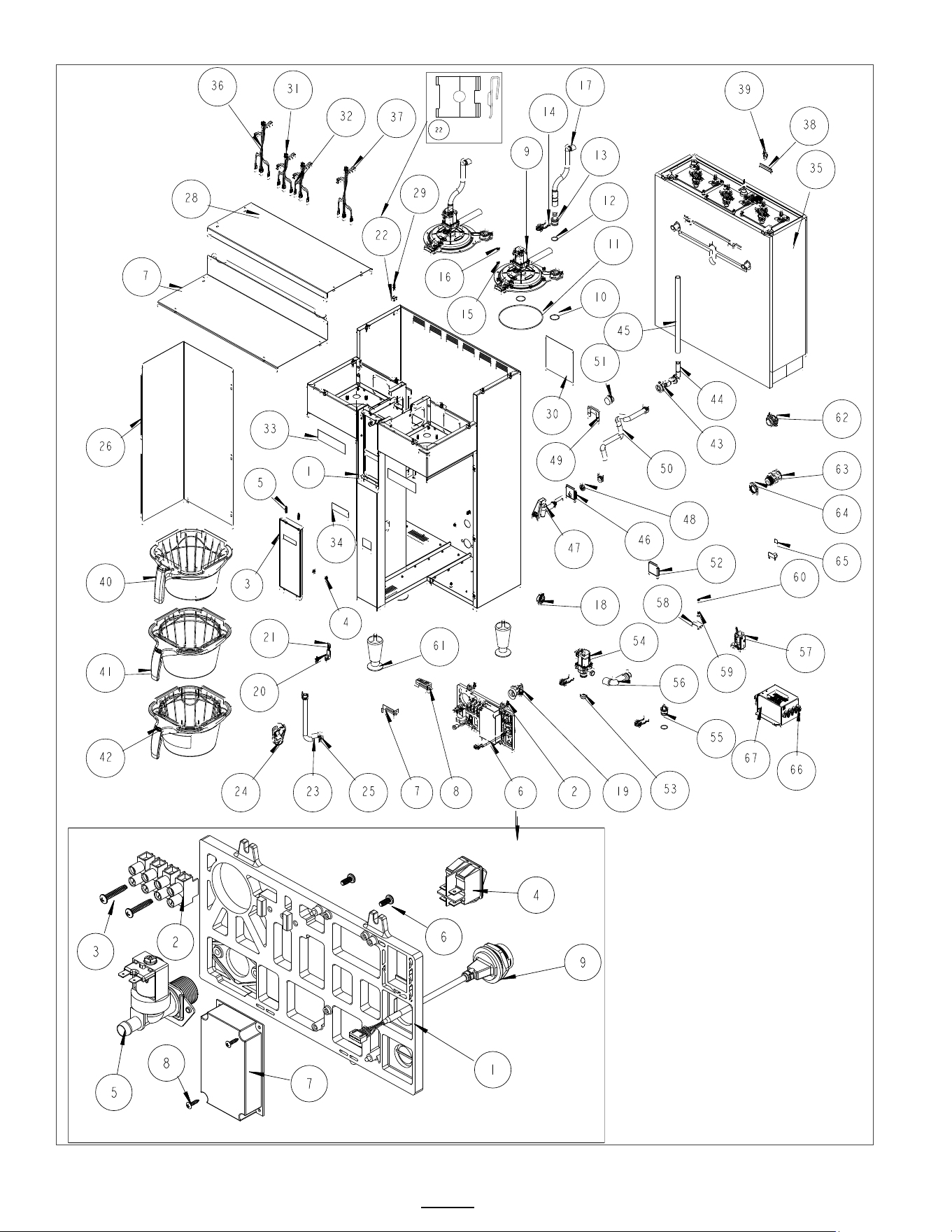
Go to fetco.com for the latest versions of all information Page 24 User Guide & Operator instructions P213 CBS-1250 Pluse0 October 2024
Parts Diagrams CBS-1252 and CBS-1253
J-Nut #22
#6 Part Number1102.00471.00
ELECTRICAL COMPONENT LATTICE

Go to fetco.com for the latest versions of all information Page 25 User Guide & Operator instructions P213 CBS-1250 Pluse0 October 2024
REF
QTY
Part number
Description Drawing 1101.00573.00, 1101.00059.00 Parts CBS-1252 and applies to CBS-1253
1
1
1111.00099.00
WELDMENT BODY, CBS-2252 1½ gallon brewer only
1
1
1111.00114.00
WELDMENT BODY, CBS-2252 2 gallon brewer only
2
6
1084.00051.00
NUT, HEX LOCKWASHER, #8-32, 18-8 ST. STL.
3
1
1102.00470.00
FRONT PANEL ASSY, DOUBLE, PLUS SERIES
4
2
1082.00029.00
SCREW, #6 X 3/8 LG, TRUSS HD PHIL, SHEET MTL
5
2
1082.00058.00
SCREW, # 8-32 X 5/8, FLAT HD, PH, 18-8 SS
6 REF
1
Reference
ELECTRICAL COMPONENT LATTICE, NEXT GEN XV+
6-1
1
1023.00350.00
ELECTRICAL MOUNTING LATTICE, COMMON
6-2
1
1052.00023.00
EUROSTRIP HE16 TERM. BLOCK, 4 POLE, 63 AMP, 18-8 AWG
6-3
2
1082.00056.00
SCREW, # 8-16 x 1" PAN HD PHIL, THREAD FORMING, FOR PLASTICS, 18-8 SS
6-4
2
1058.00024.00
SWITCH, POWER, DOUBLE POLE, 16A, 125/250 VAC
6-5
4
1057.00043.00
SOLENOID VALVE, 5.5L/min, 180 DEG, 24VDC
6-6
2
1082.00010.00
SCREW, PAN HD. PHIL. MACH., M4x10 ZINC-PLATED
6-7
1
1052.00059.00
POWER SUPPLY, 90-264VAC/24VDC, 2.25A
6-8
2
1082.00020.00
SCREW, #6 X 5/8, TRUSS HD PHIL, SHEET MTL
6-9
2
1058.00055.00
USB CONNECTOR
7
1
1097.00171.00
ADHESIVE, RGB LED BAR
8
1
1023.00390.00
LENS, LIGHT BAR, BLACK
9
2
1102.00450.00
QUICK CONNECT SRAYHEAD ASSEMBLY, BASIC [See Page 32 for expanded drawing]
10
4
1024.00107.00
O-RING, 1 3/16" OD X 1 1/16" ID X 1/16" TH, BYPASS SEAL
11
2
1024.00108.00
O-RING, 5 11/16"OD X 5 1/2" ID X 3/32" TH, BREW SEAL
12
3
1024.00106.00
O-RING, 13/16"OD X 11/16"ID X 1/16" TH, FOR QUICK CONNECT
13
2
1023.00343.00
VENT INSERT, QUICK CONNECT
14
4
1023.00342.00
QUICK CONNECT CLIP
15
20
1083.00010.00
WASHER, #10 SCREW W/NEOPRENE-BONDED SEAL
16
20
1084.00006.00
NUT, 8-32 18-8 HEX MACHINE SCREW
17
2
1024.00098.00
VENT TUBE, CBS- EXTRACTOR SERIES
18
2
1086.00004.00
BUSHING, SNAP, 1" MOUNTING HOLE
19
1
1102.00243.00
ADAPTER ASSY, 3/4" BSP x 1/4" NPT x 3/8" TUBE
20
2
1065.00009.00
GROUND LUG CONNECTOR, 14-2 AWG, ALUMINUM
21
1
1044.00012.00
LABEL GROUND, CE
22
12
1084.00011.00
NUT, CLIP ON (J-NUT), #6-32, 22-20 GA., BLK-PH FINISH
23
1
1025.00058.00
TUBE, 9/16"OD X 5/16"ID X 25.00"LG
24
1
1086.00009.00
CLAMP, 3/4" MAX TUBE OD FLOW CONTROL
25
4
1086.00003.00
UNICLAMP, 15.9 HOSE OD CLAMP
26
1
1112.00529.00
WELDMENT FRONT COVER, CBS-2250 1½ gallon brewer and 2 gallon brewer
27
1
1001.00352.00
COVER, UPPER BASE, CBS-1152 EXTRACTOR V+
28
1
1001.00399.00
COVER TOP, CBS-2252
29
12
1082.00017.00
SCREW, TRUSS HD. PHIL. MACHINE, # 6-32 X 1/2 LG.
30
1
1046.00035.00
LABEL, WARNING "TO REDUCE RISK OF ELECTRIC SHOCK OR FIRE"
31
1
1402.00097.10
WIRE HARNESS, CBS-1240/50, LOW AMP, UNIVERSAL
32
1
1402.00097.11
WIRE HARNESS ADDITION, CBS-1252, LOW AMP, UNIVERSAL
33
2
1046.00003.00
LABEL, CSD WARNING, 1.5" X 5.0"
34
1
1041.00033.00
BLACK EXTRACTOR PLUS LABEL, LASER ENGRAVED
35
1
1104.00160.00
TANK ASSEMBLY, CBS-2252, 3 X 3KW/240VAC [See additional pages for expanded drawing]
35
1
1104.00161.00
TANK ASSEMBLY, CBS-2252, 2 X 3KW/240VAC [See additional pages for expanded drawing]
35
1
1104.00162.00
TANK ASSEMBLY, CBS-2252, 3 X 4KW/240VAC [See additional pages for expanded drawing]
35
1
1104.00163.00
TANK ASSEMBLY, CBS-2252, 3 X 5KW/240VAC [See additional pages for expanded drawing]
35
1
1104.00164.00
TANK ASSEMBLY, CBS-2252, 2 X 5KW/240VAC [See additional pages for expanded drawing]
36
1
1402.00112.10
WIRE HARNESS, CBS-1252/61, HIGH AMP, 1 OR 3PH, 3 HEATERS, UL
37
1
1402.00120.10
WIRE HARNESS, 3 HEATER, HIGH AMP, 3L-N-PE, 220/380-240/415, INTL/CE
38
1
1022.00032.00
SLEEVE, Ø.50 x 2.0" LG. x 1.50" SLOT
39
1
1066.00003.00
CABLE TIE, 3-7/8" LG., BLACK
40
1
B015280BN2BK
BREW BASKET ASSY BLACK, 16" X 6", 0.280" DIA HOLE, BROWN PLUG
41
1
B001280B1BB
ASSY, 16" X 6", 0.280 DIA HOLE, BLACK
42
1
B002280B1BB
ASSY, 16" X 6", 0.280" DIA HOLE, BLACK
43
1
1024.00111.00
GROMMET, SILICONE, W/ POSITION TABS
44
1
1023.00362.00
FITTING VENT, ELBOW, .375" X .375", SELF POSITIONING
45
1
1013.00131.00
TUBE, 304SS, .625OD X .065 WALL X 11-1/2" LG.
46
1
1023.00348.00
HOT WATER INSERT, MANUAL FAUCET
47
1
1071.00055.00
FAUCET, HOT WATER, PSC-BR-8, WITH FLAT AND STEM
48
1
1084.00048.00
JAM NUT, 1/2-20 UNF, NICKEL PLATED BRASS
49
1
1003.00370.00
HOT WATER INSERT LOCK
50
1
1025.00120.00
TUBE, 9/16"OD X 5/16"ID X 13.00"LG
51
1
1024.00051.00
GROMMET, SILICONE, BLANK
52
1
1023.00349.00
HOT WATER INSERT, NO FAUCET
53
1
1023.00369.00
ORIFICE INSERT, QUICK CONNECT, 3/16" HOLE
54
1
1057.00076.00
VALVE ASSEMBLY, COMPLETE, NG, DELTROL
55
1
1023.00344.00
PLUG INSERT, QUICK CONNECT
56
1
1029.00042.00
BYPASS L-TUBE, SILICONE, 2200 SINGLE SERIES
57
1
1102.00219.00
ASSEMBLY, BB LOCKER, 24VDC
58
1
1003.00259.00
BRACKET, BREW BASKET LOCK COVER
59
2
1083.00009.00
WASHER, #6 SCREW , INTL TOOTH LOCKWASHER
60
1
1084.00010.00
NUT, HEX, #6-32, UNDERSIZED, ZINC PLATED
61
3
1073.00007.00
LEG, FLANGE FOOT, 4" HIGH
62
1
1086.00008.00
CONNECTOR, CLAMP, NON-METALLIC CABLE, 3/4"
63
1
1086.00031.00
SKINTOP, 3/4" NPT, 0.354" - 0.630" DIA CABLE, BLK
64
1
1086.00032.00
LOCKNUT, SKINTOP, 3/4" NPT, BLACK HEX
65
1
1044.00013.00
LABEL EQUIPOTENTIALITY, CE
66
1
1052.00050.00
EMI FILTER, 25A, 250/440VAC, 50/60Hz
67
1
1084.00012.00
NUT, HEX, #6-32 MACHINE SCREW
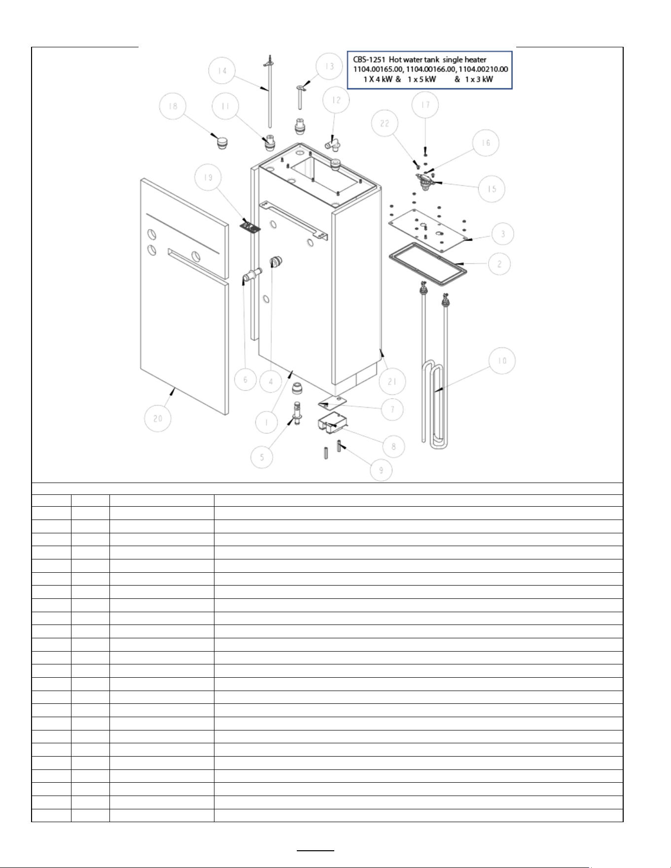
Go to fetco.com for the latest versions of all information Page 26 User Guide & Operator instructions P213 CBS-1250 Pluse0 October 2024
CBS-1251 Tank Assembly
TANK ASSY, CBS-1251 Single Heater Drawing number 1104.000165.00 & 1104.000166.00 1104.000210.00
REF
QTY
Part number
Description
1
1
1114.00172.00
WELDMENT, TANK, CBS-2251
2
1
1024.00114.00
TANK GASKET - NG HEATER PLATE, TWO ELEMENT
3
1
1114.00184.00
WELDMENT TANK HEATER BRACKET, NG-2231, SINGLE
4
3
1024.00050.00
GROMMET, SILICONE, 11.4mm ID
5
1
1023.00166.00
FITTING, COLD WATER INLET, GROMMET DESIGN
6
1
1023.00203.00
FITTING, STRAIGHT, GROMMET, .625"
7
1
1003.00140.00
ALUMINUM BRACKET FOR SSR
8
1
1052.00033.00
RELAY, SOLID STATE, 50A/480VAC, W/BUILD IN VARISTOR
9
2
1081.00042.00
STANDOFF, 1/4" HEX
10
1
1107.00005.00
HEATER ASSEMBLY, IMMERSION 3kW/240VAC (for tank # 1104.000210.00)
10
1
1107.00010.00
HEATER ASSEMBLY, IMMERSION 4kW/240VAC (for tank # 1104.00165.00)
10
1
1107.00032.00
HEATER ASSEMBLY, IMMERSION, 5kW/240VAC (for tank # 1104.00166.00)
11
2
1024.00053.00
LEVEL AND TEMP PROBE GROMMET
12
1
1023.00212.00"
FITTING, ELBOW, GROMMET, .500
13
1
1112.00019.00
PROBE WELDMENT, WATER LEVEL 2.600" LG
14
1
1102.00161.00
PROBE ASSEMBLY, TEMP. AND LLC, 8" LONG
15
1
1053.00052.00
THERMOSTAT, SINGLE SHOT, SCREW CONNECTIONS, 240V/25A
16
8
1083.00009.00
WASHER, #6 SCREW , INTL TOOTH LOCKWASHER
17
8
1084.00010.00
NUT, HEX, #6-32, UNDERSIZED, ZINC PLATED
18
1
1044.00004.00
LABEL, DANGER, HIGH VOLTAGE
19
1
1024.00051.00
GROMMET, SILICONE, BLANK
20
1
1022.00068.00
INSULATION, TANK FRONT, CBS-2151
21
1
1022.00069.00
INSULATION, TANK BACK, CBS-2151
22
2
1082.00136.00
BRASS SCREW, #8-32 X 1/4", PHILLIPS PAN HEAD
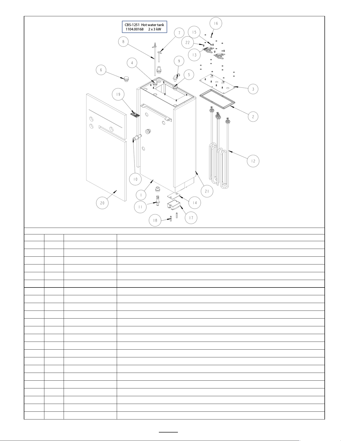
Go to fetco.com for the latest versions of all information Page 27 User Guide & Operator instructions P213 CBS-1250 Pluse0 October 2024
TANK ASSY, CBS-1251 Two Heater Drawing number 1104.000167.00 & 1104.00168.00
REF
QTY
Part number
Description
1
1
1114.00172.00
WELDMENT, TANK, CBS-2251
2
1
1024.00114.00
TANK GASKET - NG HEATER PLATE, TWO ELEMENT
3
1
1114.00176.00
WELDMENT TANK HEATER BRACKET, NG-2231
4
3
1024.00050.00
GROMMET, SILICONE, 11.4mm ID
5
1
1023.00166.00
FITTING, COLD WATER INLET, GROMMET DESIGN
6
1
1023.00203.00
FITTING, STRAIGHT, GROMMET, .625"
7
2
1003.00140.00
ALUMINUM BRACKET FOR SSR
8
2
1052.00033.00
RELAY, SOLID STATE, 50A/480VAC, W/BUILD IN VARISTOR
9
4
1081.00042.00
STANDOFF, 1/4" HEX
10
2
1107.00037.00
HEATER ASSEMBLY, IMMERSION 2300W/240VAC
10
2
1107.00005.00
HEATER ASSEMBLY, IMMERSION 3000W/240VAC
11
2
1024.00053.00
LEVEL AND TEMP PROBE GROMMET
12
1
1023.00212.00
FITTING, ELBOW, GROMMET, .500"
13
1
1112.00019.00
PROBE WELDMENT, WATER LEVEL 2.600" LG
14
1
1102.00161.00
PROBE ASSEMBLY, TEMP. AND LLC, 8" LONG
15
2
1053.00052.00
THERMOSTAT, SINGLE SHOT, SCREW CONNECTIONS, 240V/25A
16
10
1083.00009.00
WASHER, #6 SCREW , INTL TOOTH LOCKWASHER
17
10
1084.00010.00
NUT, HEX, #6-32, UNDERSIZED, ZINC PLATED
18
1
1024.00051.00
GROMMET, SILICONE, BLANK
19
1
1044.00004.00
LABEL, DANGER, HIGH VOLTAGE
20
1
1022.00068.00
INSULATION, TANK FRONT, CBS-2151
21
1
1022.00069.00
INSULATION, TANK BACK, CBS-2151
22
4
1082.00136.00
BRASS SCREW, #8-32 X 1/4", PHILLIPS PAN HEAD
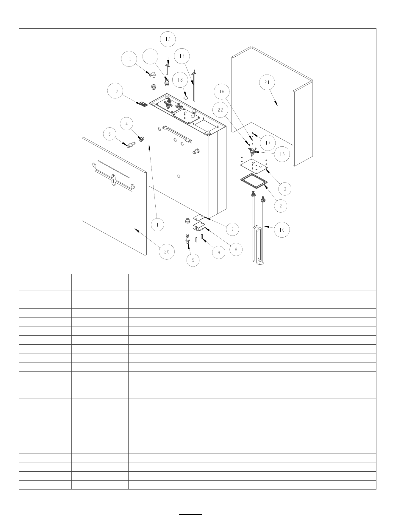
Go to fetco.com for the latest versions of all information Page 28 User Guide & Operator instructions P213 CBS-1250 Pluse0 October 2024
CBS-1252 and CBS1253 Tank Assembly
CBS-1252 Hot Water Tank Drawing 1104.00161.00 & 1104.00164.00
Ref#
Qty
Part number
Description
1
1
1114.00164.00
WELDMENT TANK, CBS-2252, LASER
2
3
1024.00115.00
TANK GASKET - NG HEATER PLATE, ONE ELEMENT
3
3
1114.00181.00
WELDMENT TANK HEATER BRACKET, NG-2232
4
5
1024.00050.00
GROMMET, SILICONE, 11.4mm ID
5
1
1023.00166.00
FITTING, COLD WATER INLET, GROMMET DESIGN
6
2
1023.00203.00
FITTING, STRAIGHT, GROMMET, .625"
7
2
1003.00140.00
ALUMINUM BRACKET FOR SSR
8
2
1052.00033.00
RELAY, SOLID STATE, 50A/480VAC, W/BUILD IN VARISTOR
9
4
1081.00042.00
STANDOFF, 1/4" HEX
10
2
1107.00005.00
ASSEMBLY, IMMERSION HEATER, 3000W, 240VAC
10
2
1107.00032.00
ASSEMBLY, IMMERSION HEATER, 5000W, 240VAC
11
2
1024.00053.00
LEVEL AND TEMP PROBE GROMMET
12
2
1023.00212.00
FITTING, ELBOW, GROMMET, .500"
13
1
1112.00019.00
PROBE WELDMENT, WATER LEVEL 2.600" LG
14
1
1102.00161.00
PROBE ASSEMBLY, TEMP. AND LLC, 8" LONG
15
2
1053.00052.00
THERMOSTAT, SINGLE SHOT, SCREW CONNECTIONS, 240V/25A
16
16
1083.00009.00
WASHER, #6 SCREW , INTL TOOTH LOCKWASHER
17
16
1084.00010.00
NUT, HEX, #6-32, UNDERSIZED, ZINC PLATED
18
2
1024.00054.00
GROMMET, SILICONE PLUG
19
1
1044.00004.00
LABEL, DANGER, HIGH VOLTAGE
20
1
1022.00070.00
INSULATION, TANK FRONT, CBS-2152
21
1
1022.00071.00
INSULATION, TANK BACK, CBS-2152
22
4
1082.00136.00
BRASS SCREW, #8-32 X 1/4", PHILLIPS PAN HEAD
CBS-1252 Hot water tank
1104.00161.
00; 1104.00164
.00
2 X 3kW
; 2x 5 kW
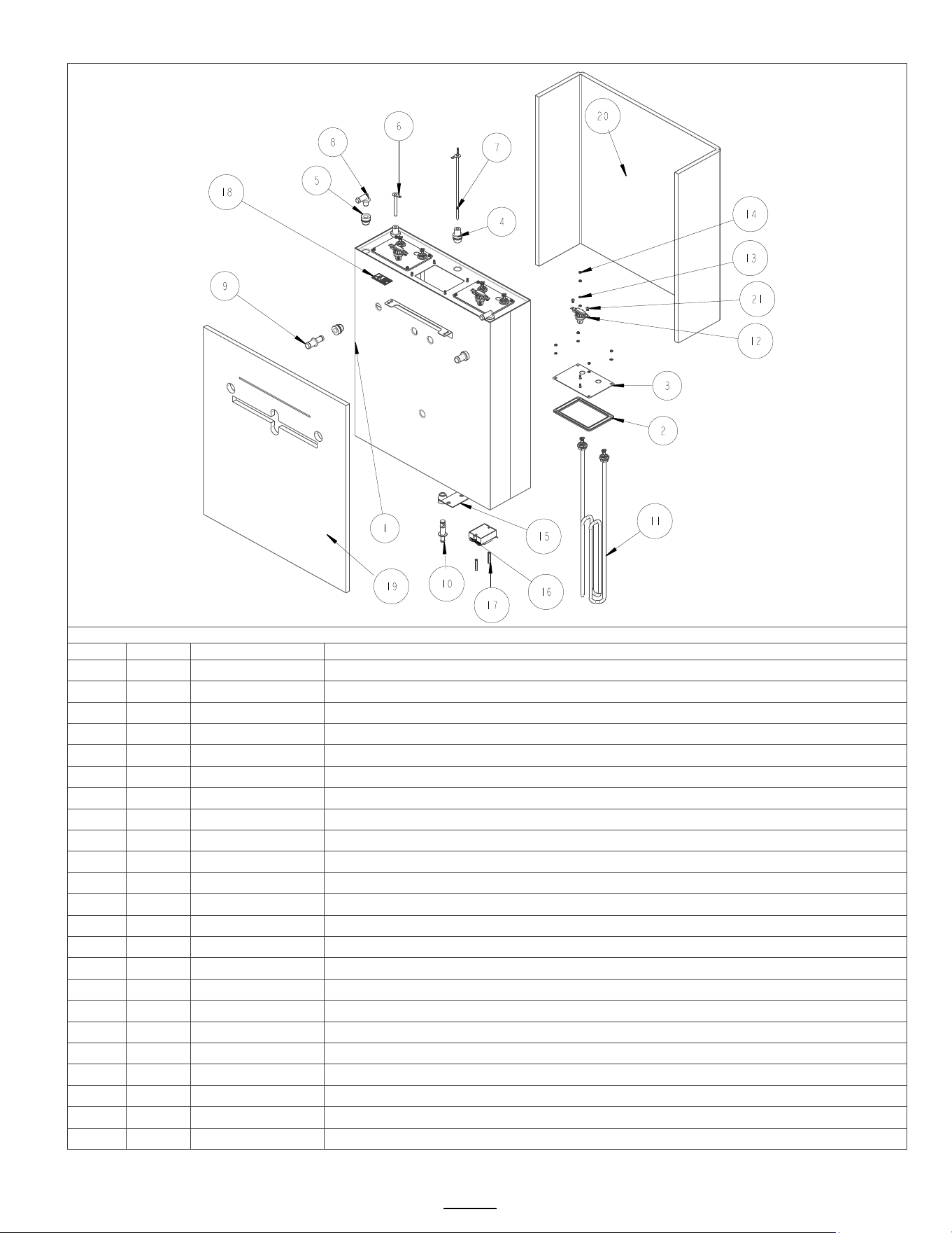
Go to fetco.com for the latest versions of all information Page 29 User Guide & Operator instructions P213 CBS-1250 Pluse0 October 2024
.
CBS-1252 and CBS-1253 Hot Water Tank Drawing 1104.00160.00; 1104.00162.00; 1104,00163.00
Ref#
Qty
Part number
Description
1
1
1114.00164.00
WELDMENT TANK, CBS-2252, LASER
2
3
1024.00115.00
TANK GASKET - NG HEATER PLATE, ONE ELEMENT
3
3
1114.00181.00
WELDMENT TANK HEATER BRACKET, NG-2232
4
2
1024.00053.00
LEVEL AND TEMP PROBE GROMMET
5
5
1024.00050.00
GROMMET, SILICONE, 11.4mm ID
6
1
1112.00019.00
PROBE WELDMENT, WATER LEVEL 2.600" LG
7
1
1102.00161.00
PROBE ASSEMBLY, TEMP. AND LLC, 8" LONG
8
2
1023.00212.00
FITTING, ELBOW, GROMMET, .500"
9
2
1023.00203.00
FITTING, STRAIGHT, GROMMET, .625"
10
1
1023.00166.00
FITTING, COLD WATER INLET, GROMMET DESIGN
11
3
1107.00005.00
ASSEMBLY, IMMERSION HEATER, 3000W, 240VAC
11
3
1107.00010.00
ASSEMBLY, IMMERSION HEATER, 4000W, 240VAC
11
3
1107.00032.00
ASSEMBLY, IMMERSION HEATER, 5000W, 240VAC
12
3
1053.00052.00
THERMOSTAT, SINGLE SHOT, SCREW CONNECTIONS, 240V/25A,
13
18
1083.00009.00
WASHER, #6 SCREW , INTL TOOTH LOCKWASHER
14
18
1084.00010.00
NUT, HEX, #6-32, UNDERSIZED, ZINC PLATED
15
3
1003.00140.00
ALUMINUM BRACKET FOR SSR
16
3
1052.00033.00
RELAY, SOLID STATE, 50A/480VAC, W/BUILD IN VARISTOR
17
6
1081.00042.00
STANDOFF, 1/4" HEX
18
1
1044.00004.00
LABEL, DANGER, HIGH VOLTAGE
19
1
1022.00070.00
INSULATION, TANK FRONT, CBS-2152
20
1
1022.00071.00
INSULATION, TANK BACK, CBS-2152
21
6
1082.00136.00
BRASS SCREW, #8-32 X 1/4", PHILLIPS PAN HEAD
CBS-1252
Hot water tank
1104
.00160.
00; 1104.00162.00; 1104.00163.00
3 X 3kW
; 3 X 4 kW & 3 x 5 kW
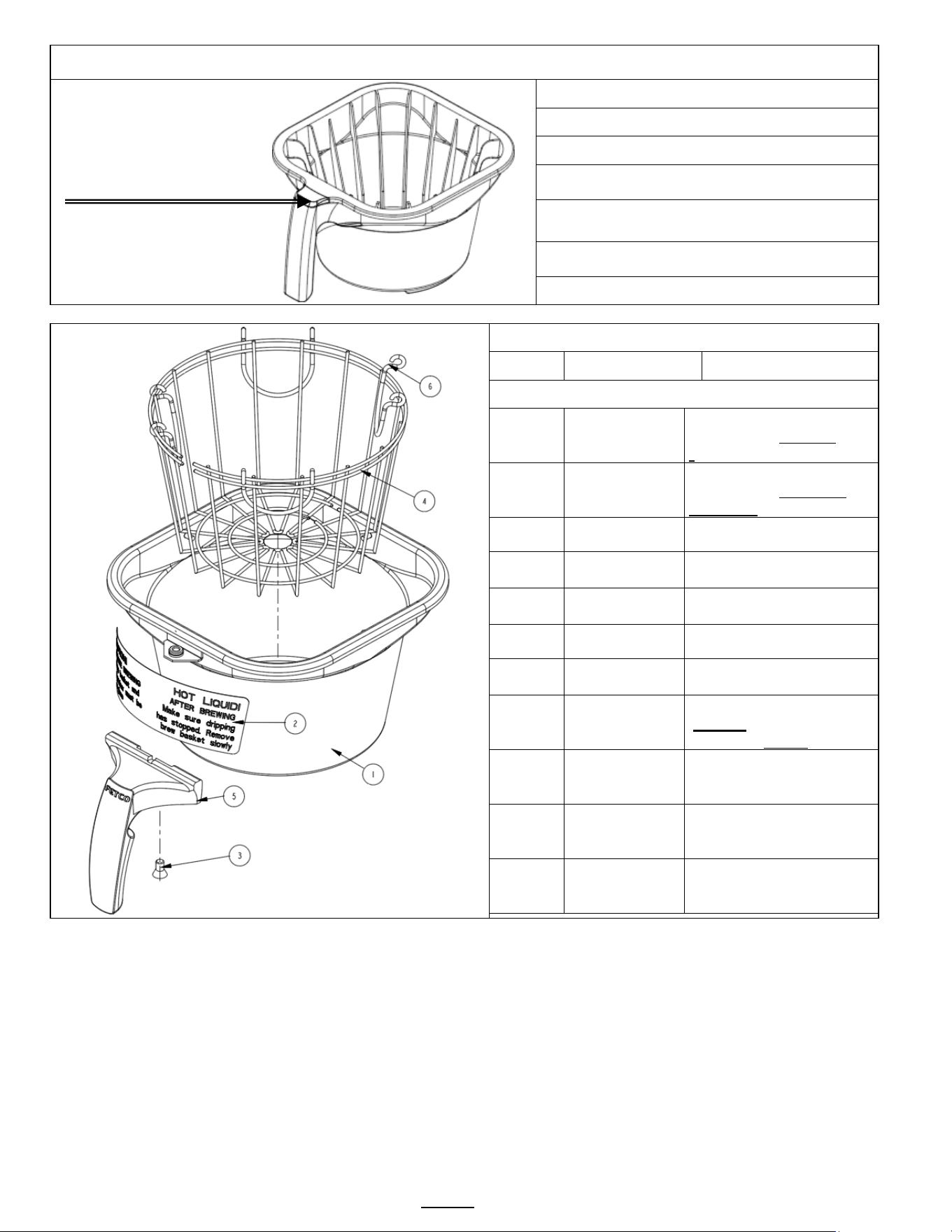
Go to fetco.com for the latest versions of all information Page 30 User Guide & Operator instructions P213 CBS-1250 Pluse0 October 2024
Standard Plastic Brew Basket
Part Number B015280BN2BK 0.280” diameter hole
Brew basket handle plug
for polymeric brew baskets is
available in optional colors.
Part Number Plug Insert color
1023.00195.00
BROWN PLUG, BB HANDLE
1023.00194.00
BLACK PLUG, BB HANDLE
1023.00190.00
RED PLUG, BB HANDLE
1023.00191.00
GREEN PLUG, BB HANDLE
1023.00192.00
ORANGE PLUG, BB HANDLE
1023.00180.00
BLUE PLUG, BB HANDLE
Standard Stainless Steel Brew Basket
Ref# Part Number Description
B001280B1
Complete Stainless Steel
Brew basket no clips
(Standard)
B002280B1
Complete Stainless Steel
Brew basket with clips
(Optional)
1 1112.00058.00 BB brew cone WLDMNT
2 1046.00025.00
BREW BASKET
WARNING LABEL
3 1082.00040.00
SCREW, 1/4-20 X .5, FL
HD, PH., W/NYLN
4 1009.00005.00 WIRE BASKET
5 1102.00064.00
HANDLE W/MAGNET
ASY, BLACK
6 1009.00003.00
CLIP, WIRE BASKET,
NOTE!:
Requires 4 clips
Optional
colored
handle
1102.00065.00
HANDLE W/MAGNET
ASY, RED
Optional
colored
handle
1102.00066.00
HANDLE W/MAGNET
ASY, GREEN
Optional
colored
handle
1102.00067.00
HANDLE W/MAGNET
ASY, ORANGE
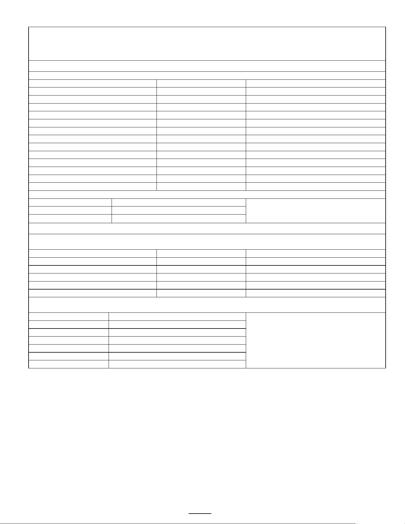
Go to fetco.com for the latest versions of all information Page 31 User Guide & Operator instructions P213 CBS-1250 Pluse0 October 2024
Specialty Brew Baskets for Iced Tea/Tea and Specialty Coffee Brewing.
Below are brew baskets with expanded or reduced orifice sizes. Changing the brew basket orifice diameter may require
changing brew time and pulses to enhance extraction and prevent basket overflow or short potting..
See Page 7&8 to modify the brew recipes
Stainless Steel Brew Baskets
16" X 6" for 1 ½ gallon and 2 gallon brewers. Use 15” X 5 ½” filter paper for all models
Part Number
Handle Color
Orifice diameter
B001280B1* Standard NO CLIPS
BLACK - STANDARD
0.280” STANDARD
B002280B1 WITH CLIPS
BLACK -
0.280
B001280R1 NO CLIPS
RED
0.280
B002280R1 WITH CLIPS
RED
0.280
B001280O1 NO CLIPS
ORANGE
0.280
B002280O1 WITH CLIPS
ORANGE
0.280
B001280G1 NO CLIPS
GREEN
0.280
B002280G1 WITH CLIPS
GREEN
0.280
B001280B1L (“COFFEE” label on basket)
BLACK -
0.280”
b001206b1(“ICED TEA” label on basket)
BLACK -
0.206 REDUCED
B001280B1
BLACK -
0.158”/4mm REDUCED
B001110G1 (“ICED TEA” label on basket)
GREEN
0.110 REDUCED
b001110b1 (“ICED TEA” label on basket)
BLACK -
0.110 REDUCED
Colored handles for stainless steel brew baskets
1102.00065.00
Complete Handle W/Magnet RED
1102.00066.00
Complete Handle W/Magnet GREEN
1102.00066.00
Complete Handle W/Magnet ORANGE
Plastic Brew Baskets
16" X 6" for 1 ½ gallon and 2 gallon brewers. Use 15” X 5 ½” filter paper for all models
Colored plugs available for handle as identifier
Part Number
Handle PLUG color
Orifice diameter
B015280BN2BK* – Black Body
Brown - STANDARD
0.280” STANDARD
B015280R2BK – Black Body
RED
0.280
B015280BN2 – Brown Body
Brown
0.280
b015158bn2 – Dark Grey Body
Brown
0.158”/4mm REDUCED
b015140g2bk – Black Body
Green
0.140” orifice REDUCED
Below are colored plugs that fit the handle of plastic brew baskets. This helps to quickly identify the basket.
Note that the plugs only fit plastic brew baskets. Colored handles are available for stainless steel brew baskets,
Part Number
Plug Insert color
1023.00195.00
BROWN PLUG, BB HANDLE
1023.00194.00
BLACK PLUG, BB HANDLE
1023.00190.00
RED PLUG, BB HANDLE
1023.00191.00
GREEN PLUG, BB HANDLE
1023.00192.00
ORANGE PLUG, BB HANDLE
1023.00180.00
BLUE PLUG, BB HANDLE
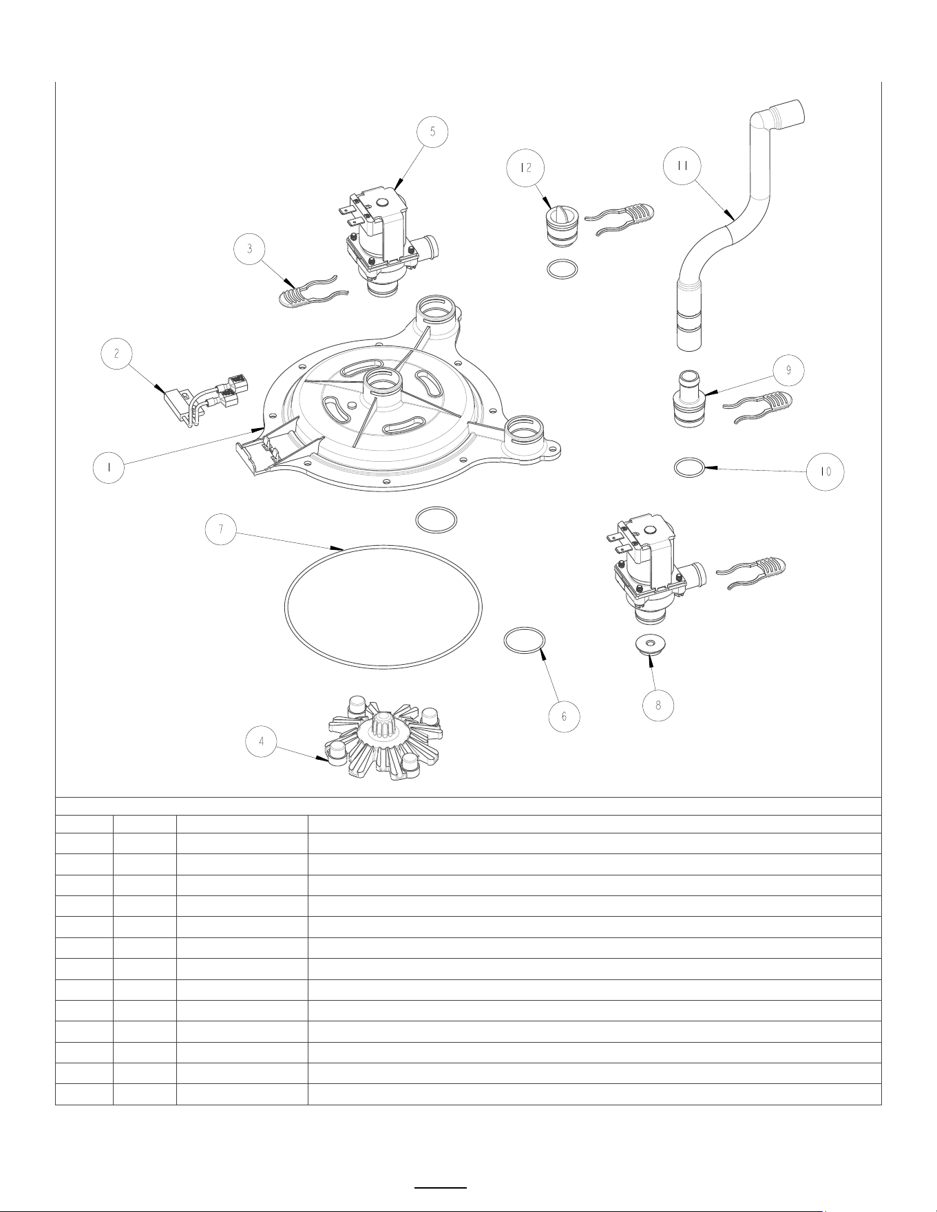
Go to fetco.com for the latest versions of all information Page 32 User Guide & Operator instructions P213 CBS-1250 Pluse0 October 2024
Quick connect spray head assembly
CBS-2151; CBS-1252 and CBS-1253 1102.00450.00 QUICK CONNECT SRAY HEAD ASSEMBLY
Ref#
Qty
Part number
Description
1
1
1000.00144.00
BASE, QUICK CONNECT SPRAY HEAD
2
1
1102.00113.00
SWITCH, REED, ASSEMBLY
3
3
1023.00342.00
QUICK CONNECT CLIP
4
1
1102.00043.00
CASCADE SPRAY DOME, CBS-2050/60'S
5
2
1057.00076.00
VALVE ASSEMBLY, COMPLETE, NG, DELTROL (interchangeable with 1057.00078.00)
5
2
1057.00078.00
VALVE ASSEMBLY, COMPLETE, NG, RPE (interchangeable with 1057.00076.00)
6
2
1024.00107.00
O-RING, 1 3/16" OD X 1 1/16" ID X 1/16" TH, BYPASS SEAL
7
1
1024.00108.00
O-RING, 5 11/16"OD X 5 1/2" ID X 3/32" TH, BREW SEAL
8
1
1023.00369.00
ORIFICE INSERT, QUICK CONNECT, 3/16" HOLE (orange)
9
1
1023.00343.00
VENT INSERT, QUICK CONNECT
10
2
1024.00106.00
O-RING, 13/16"OD X 11/16"ID X 1/16" TH, FOR QUICK CONNECT
11
1
1024.00098.00
VENT TUBE, CBS- EXTRACTOR SERIES
12
1
1023.00344.00
PLUG INSERT, QUICK CONNECT
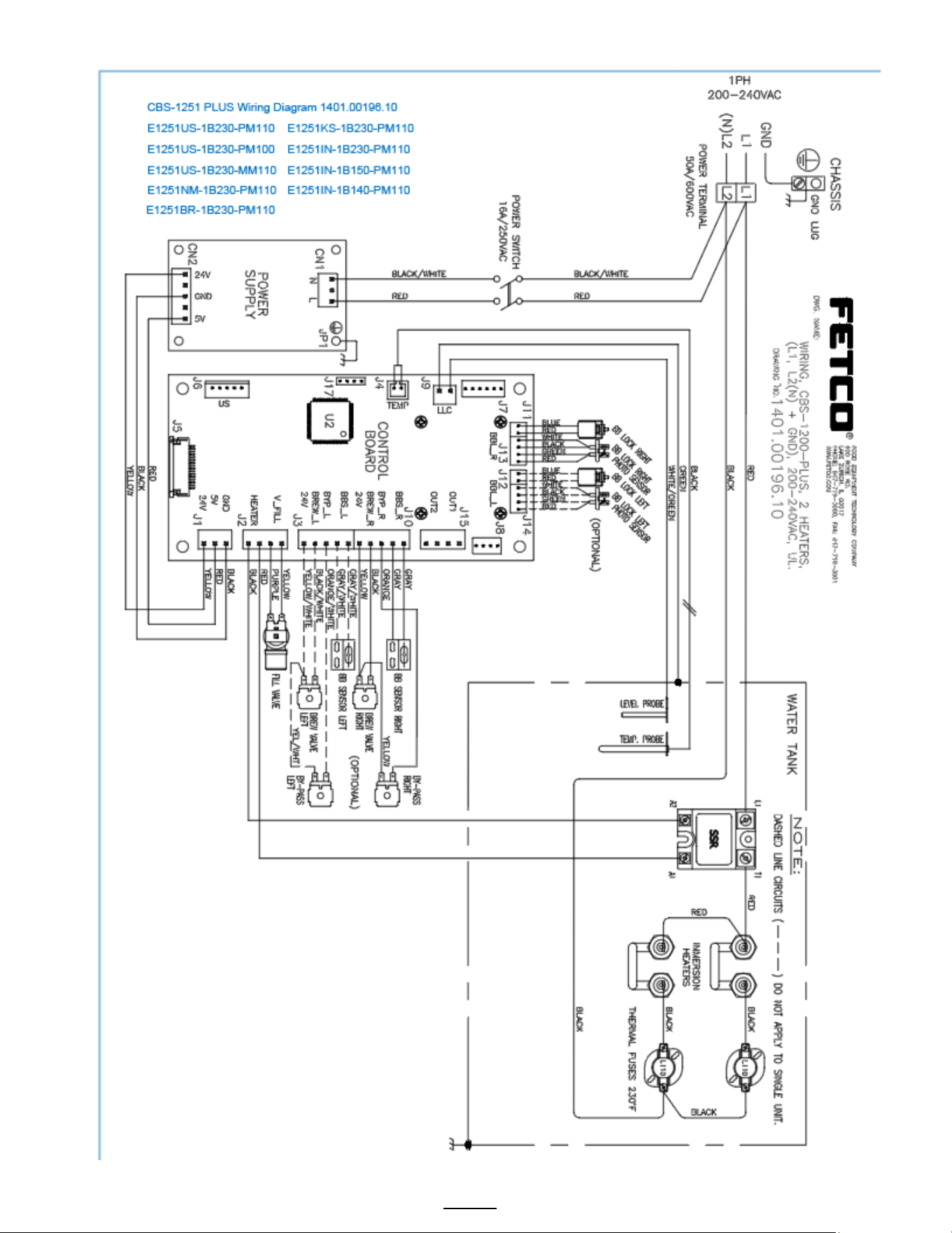
Go to fetco.com for the latest versions of all information Page 33 User Guide & Operator instructions P213 CBS-1250 Pluse0 October 2024
Wiring Diagrams
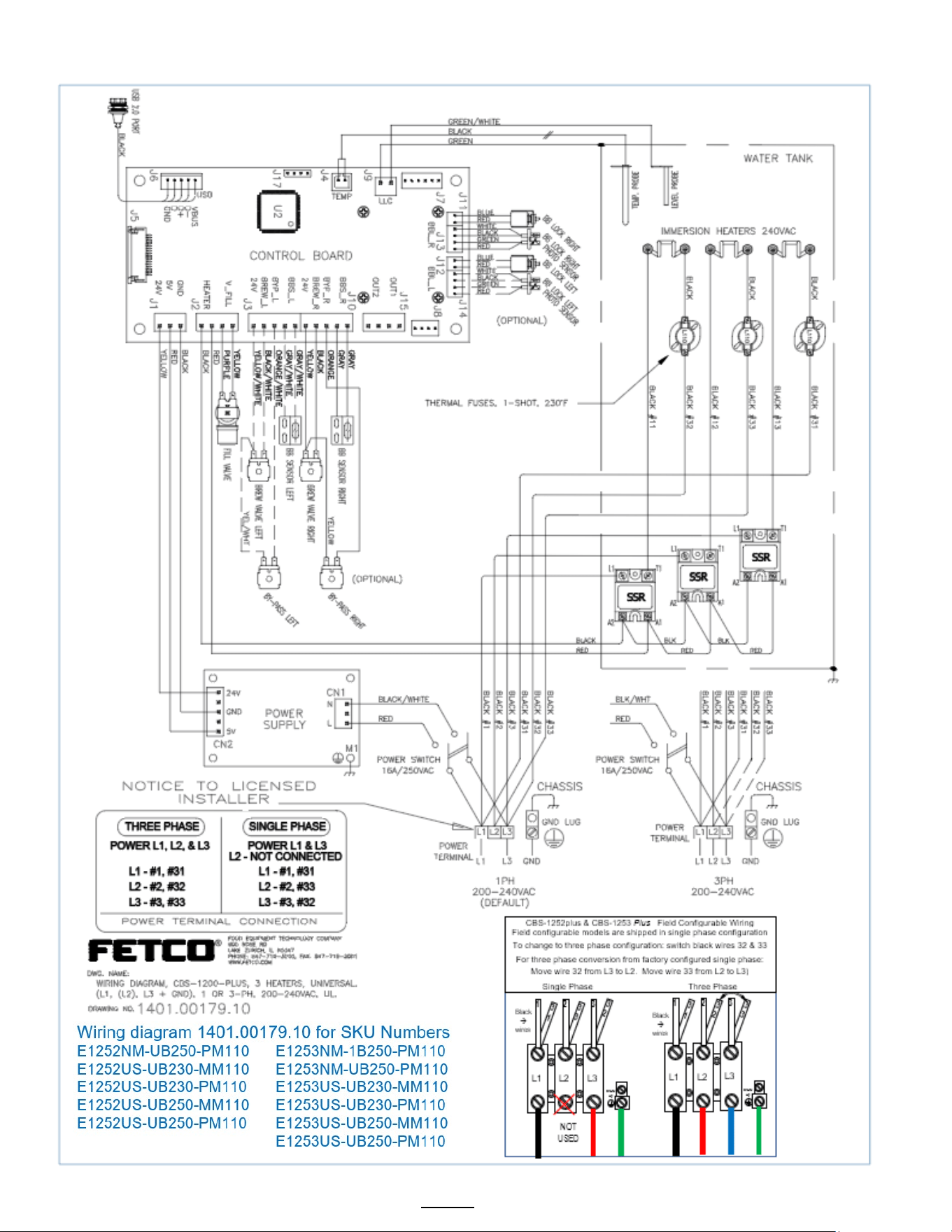
Go to fetco.com for the latest versions of all information Page 34 User Guide & Operator instructions P213 CBS-1250 Pluse0 October 2024
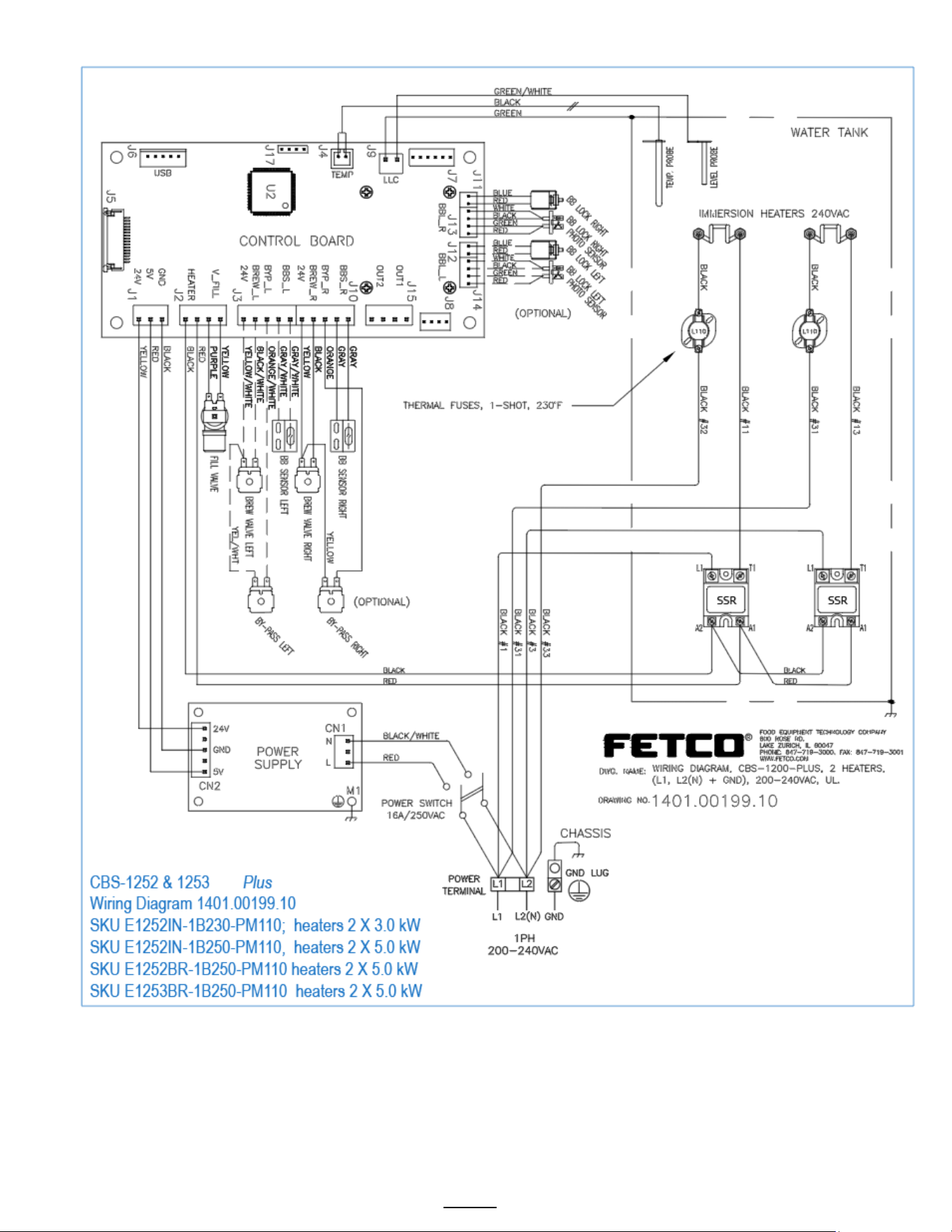
Go to fetco.com for the latest versions of all information Page 35 User Guide & Operator instructions P213 CBS-1250 Pluse0 October 2024
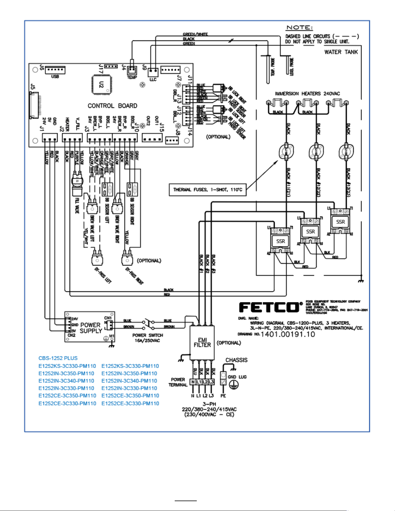
Go to fetco.com for the latest versions of all information Page 36 User Guide & Operator instructions P213 CBS-1250 Pluse0 October 2024
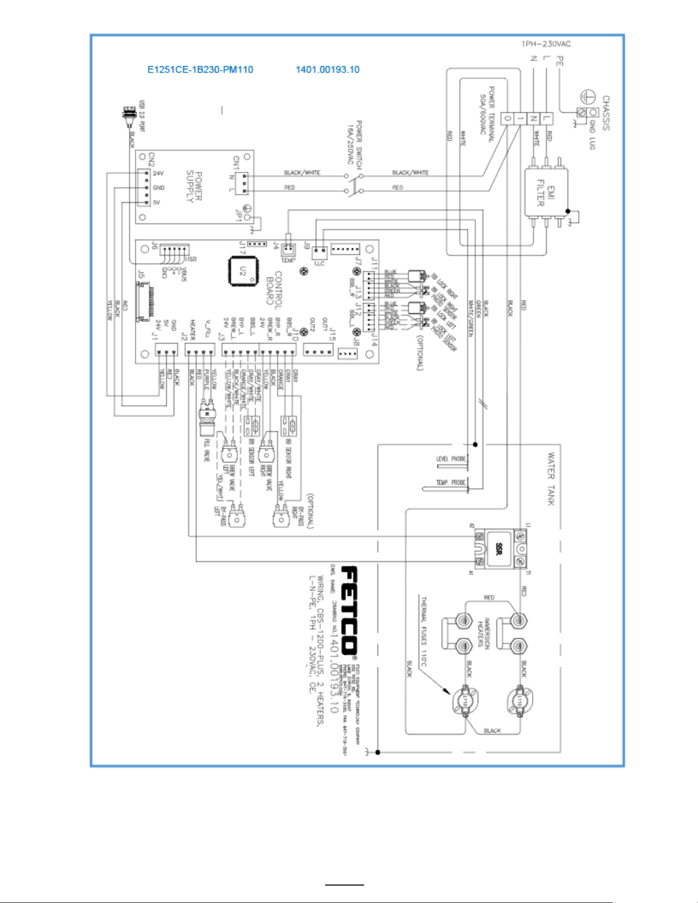
Go to fetco.com for the latest versions of all information Page 37 User Guide & Operator instructions P213 CBS-1250 Pluse0 October 2024
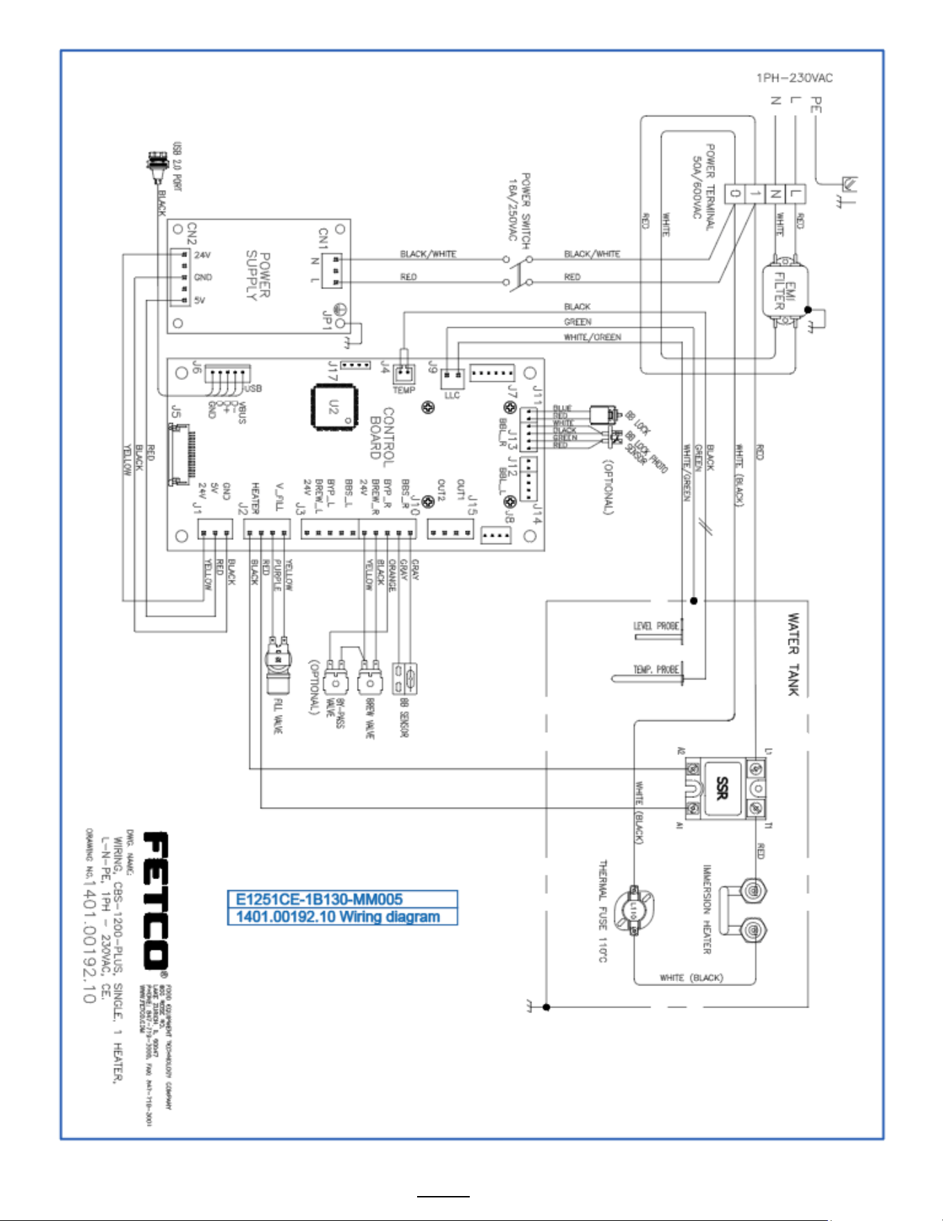
Go to fetco.com for the latest versions of all information Page 38 User Guide & Operator instructions P213 CBS-1250 Pluse0 October 2024
