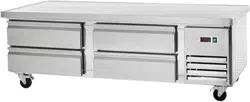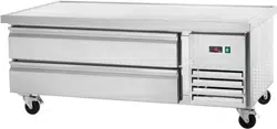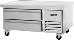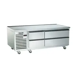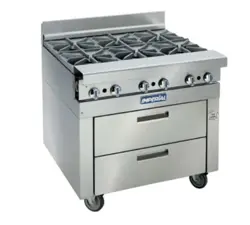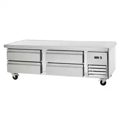
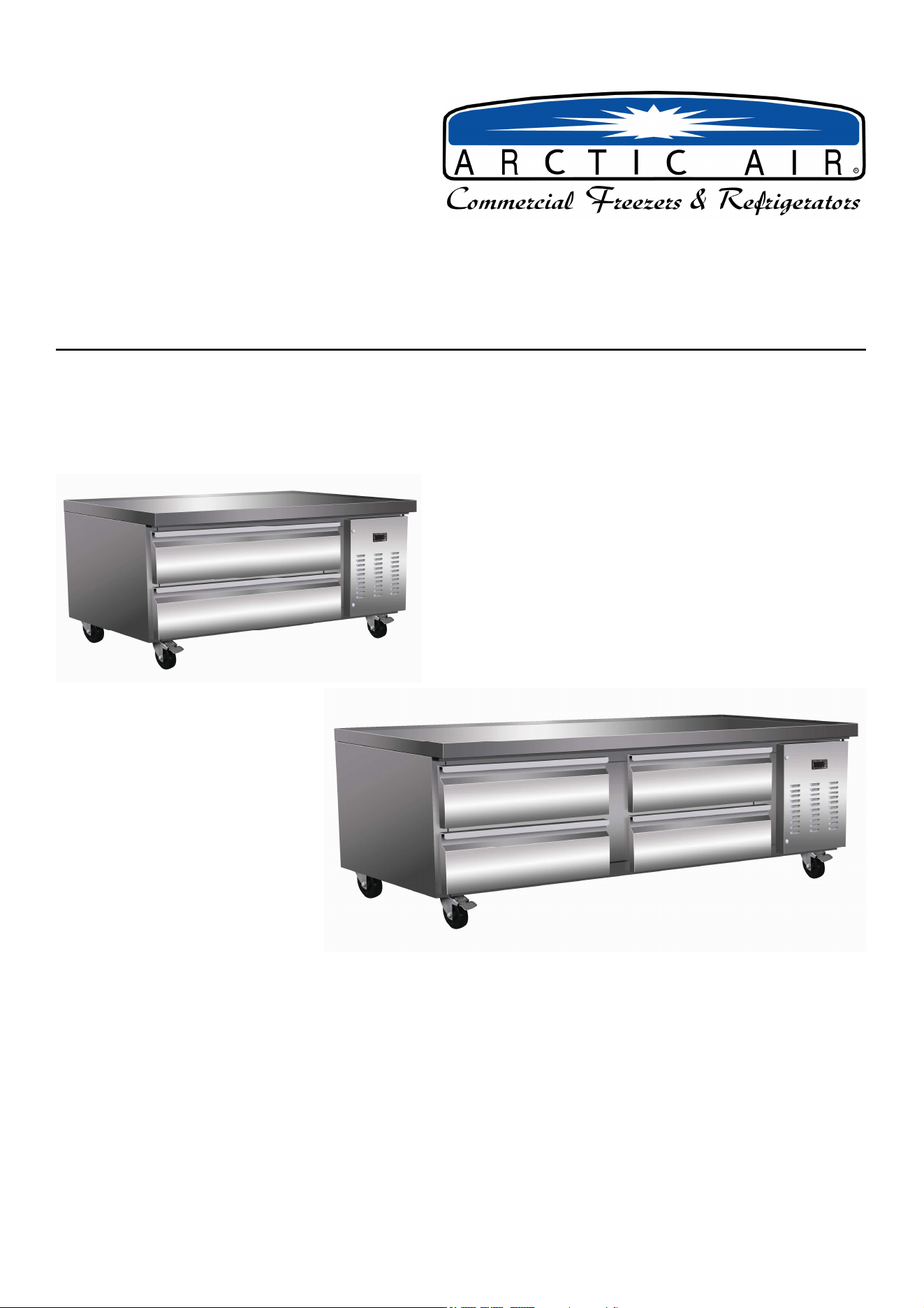
Chef Base Refrigerators
Service, Installation and Care Manual
Please read this manual completely before attempting to install or operate this equipment.
Notify carrier of damage! Inspect all components immediately.
IMPORTANT INFORMATION
READ BEFORE USE
PLEASE SAVE THESE INSTRUCTIONS!
Service and Installation Manual
2
COMMECIAL REFRIGERATOR SAFETY
Your safety and the safety of others are very important.
We have provided many important safety messages in this manual and on your appliance. Always read and
obey all safety messages.
Our product instructions will be uploaded on our company official website.
This is the Safety Alert Symbol. This symbol alerts you to potential hazards that can
kill or injure you and others. All safety messages will follow the Safety Alert Symbol
and either the words” DANGER”, “WARNING” or “CAUTION”.
Danger means that failure to heed this safety
statement may result in severe personal injury or
death.
Warning means that failure to heed this safety
statement may result in extensive product
damage, serious personal injury, or death.
Caution means that failure to heed this safety
statement may result in minor or moderate
personal injury, or property or equipment damage.
All safety messages will alert you to what the potential hazard is, tell you how to reduce the chance of injury,
and let you know what can happen if the instructions are not followed.
If the supply cord is damaged, it must be replaced by the manufacturer, its service agent or similarly
qualified persons in order to avoid a hazard.
This appliance is not intended for use by persons (including children) with reduced physical, sensory or
mental capabilities, or lack of experience and knowledge, unless they have been given supervision or
instruction concerning use of the appliance by a person responsible for their safety.
Children should be supervised to ensure that they do not play with the appliance.
This appliance can be used by children aged from 8 years and above and persons with reduced physical
sensory or mental capabilities or lack of experience and knowledge if they have been given supervision or
instruction concerning use of the appliance in a safe way and understand the hazards involved. Children
shall not play with the appliance. Cleaning and user maintenance shall not be made by children without
supervision.
Keep the appliance and its cord out of reach of children less than 8 years.
Do not store explosive substances such as aerosol cans with a flammable propellant in this appliance.
The appliance use flammable insulation blowing gas C5H10, disposal of the appliance shall in accordance
with the regulations of local authorities.
Service and Installation Manual
3
Th
e key for appliance electric box should be safe kept by qualified persons in order to avoid a hazard
WARNING: Keep ventilation openings, in the appliance enclosure or in the built-in structure, clear of
obstruction.
WARNING: Do not use mechanical devices or other means to accelerate the defrosting process, other than
those recommended by the manufacturer.
WARNING: Do not damage the refrigerant circuit.
WARNING: Do not use electrical appliances inside the food storage compartments of the appliance, unless
they are of the type recommended by the manufacturer.
Handling, moving, and use of the refrigerator or freezer to avoid either damaging the refrigerant tubing, or
increasing the risk of a leak
L’opération, le mouvement et l’utilisation du réfrigérant ou le congélateur doivent éviter les dommages du
tuyau réfrigérant ou le rique de la fuite.
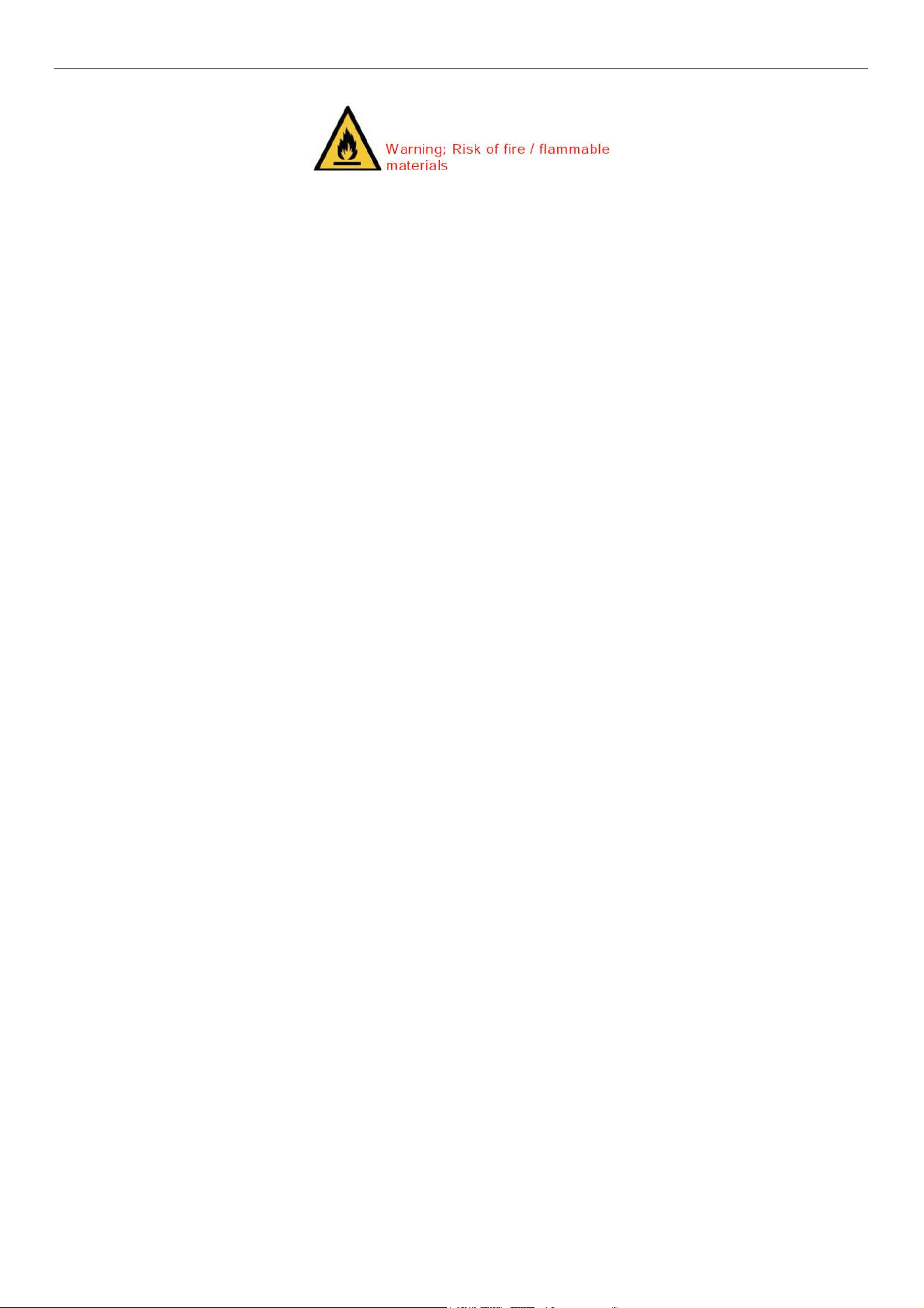
Caution – Risk of Fire or Explosion due to Flammable Refrigerant Used. Follow Handling
Instructions Carefully in Compliance with U.S. Government Regulations.
Component parts shall be replaced with like components and that servicing shall be done by factory
authorized service personnel, so as to minimize the risk of possible ignition due to incorrect parts or
improper service.
Les pièces de rechange doivent être remplacées par les components relatifs et les opérations doivent être
faites par les professionnels afin de minimaliser le risque d’allumage à cause des parts incorrects ou des
opérations impropres.
CAUTION – Risk Of Fire Or Explosion Due To Puncture Of Refrigerant Tubing; Follow Handling Instructions
Carefully. Flammable Refrigerant Used
DANGER: Risk of child entrapment. Before you throw away your old refrigerator or freezer:
Take off the doors
Leave the shelves in place so that children may not easily climb inside

Service and Installation Manual
4
CONTENTS
RECEIVING & INSPECTING EQUIPMENT........4
SPECIFICATIONS.........5
INSTALLATION..........6
OPERATION..........7
MAINTENANCE........9
WIRING DIAGRAM........11
All rights reserved. Reproduction without written permission is prohibited.
SERIAL NUMBER INFORMATION
The serial number of all self-contained refrigerators is located outside the unit on the left hand side near the
top on the wall and also on the back of the unit.
Always have the serial number of your unit available when calling for parts or service.
This manual covers standard units only.
RECEIVING AND INSPECTING THE EQUIPMENT
Even though most equipment is shipped crated, care should be taken during unloading so the equipment is
not damaged while being moved into the building.
1. Visually inspect the exterior of the package and skid or container. Any damage should be noted and
reported to the delivering carrier immediately.
2. If damaged, open and inspect the contents with the carrier.
3. In the event that the exterior is not damaged, yet upon opening, there is concealed damage to the
equipment, notify the carrier. Notification should be made verbally as well as in written form.
4. Request an inspection by the shipping company of the damaged equipment. This should be done within
10 days from receipt of the equipment.
5. Be certain to check the compressor compartment housing and visually inspect the refrigeration package.
Be sure lines are secure and base is still intact.
6. Freight carriers can supply the necessary damage forms upon request.
7. Retain all crating material until an inspection has been made or waived.
Service and Installation Manual
5
SPECIFICATION
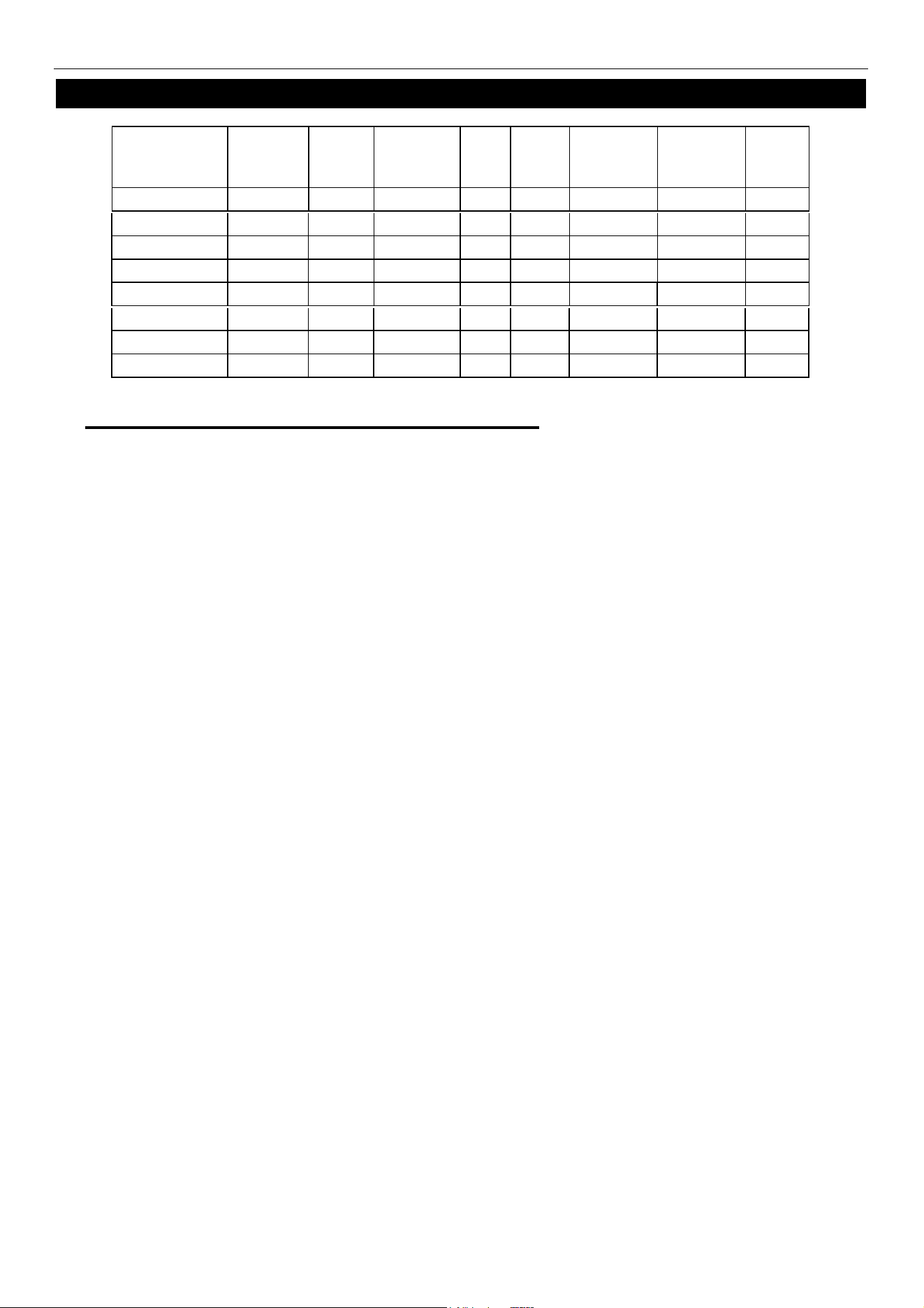
***REQUIRED OPERATING CONDITIONS:
MODEL# V/Hz/Ph
AMPS
STORAGE
CAPACITY
Cu-ft
HP
BTU
CHARGE
OZ
SHIP
WEIGHT
LBS
NEMA
PLUG
115/60/1
1.5 3.9 1/3
900
2.82 205 5-15P
115/60/1
2.1 6.5 1/3
900
2.82 260 5-15P
115/60/1
2.1 8.8 1/3
900
2.82 302 5-15P
115/60/1
2.1 11.1 1/3
900
2.82 353 5-15P
ARCB36Z
ARCB60Z
ARCB72Z
ARCB48Z
115/60/1
1.5 3.9 1/3
900
2.82 205 5-15P
115/60/1
2.1 6.5 1/3
900
2.82 260 5-15P
115/60/1
2.1 8.8 1/3
900
2.82 302 5-15P
115/60/1
2.1 11.1 1/3
900
2.82 353 5-15P
ARCB36CZ
ARCB60CZ
ARCB72CZ
ARCB48CZ
• M
inimum clearance of 4” required between bottom of cooking equipment heating element
a
n
d
ARCB top. Failure to provide clearance voids manufacturer warranty.
• Cou
ntertop cooking equipment should be used in conjunction with the manufacturer
supplied legs.
• Installation of a heat shield (supplied by others) is recommended under the cook top for
optimum performance and warping to the stainless steel with a cook top exceeding 280
degrees.
Service and Installation Manual
6
INSTALLATION
Location
Units represented in this manual are intended for indoor use only. Be sure the location chosen has a floor
strong enough to support the total weight of the cabinet and contents. A fully loaded unit can weigh as much
as 1500 pounds. Reinforce the floor as necessary to provide for maximum loading. For the most efficient
refrigeration, be sure to provide good air circulation inside and out.
Inside cabinet
Do not pack the units so full that air cannot circulate. The refrigerated air is discharged at the rear of the unit.
It is important to allow for proper air flow from the rear to the front of the unit. Obstructions to this air flow can
cause evaporator coil freeze ups and loss of temperature or overflow of water from the evaporator drain pan.
However, bags and other items can still be located to the far rear of the cabinet. Air is brought into the
evaporator coil with fans. Prevent obstruction to allow the outlet or inlet of air f
low.
Outside cabinet
Be sure that the unit has access to ample air. It is recommended that the unit be installed no closer than 3"
from any wall
Leveling
A level cabinet looks better and will perform better because the doors will line up with the frames properly.
Use a level to make sure the unit is level from front to back and side to side. Units supplied with legs will
have adjustable bullet feet to make the necessary adjustments. If the unit is supplied with casters, no
adjustments are available. Ensure the floor where the unit is to be located is level.
Stabilizing
All models are supplied with casters for your convenience. It is very important, however, that the cabinet
be installed in a stable condition with the front wheels locked while in use.
Should it become necessary to lay the unit on its side or back for any reason, allow at least 24 hours before
start-up to allow compressor oil to flow back to place. Failure to meet this requirement can cause
compressor failure and unit damage.
Unit repairs will not be subject to standard unit warranties if due to improper installation
procedures.
Electrical connection
Refer to the amperage data on page 3, the serial tag, your local code or the National Electrical Code to be
sure the unit is connected to the proper power source. A dedicated 20 Amp circuit is required for each
unit. Improper electrical connection will void warranty.
Use of extension cords is strictly prohibited and will also void warranty.
The unit must be turned OFF and disconnected from the power source whenever
performing service, maintenance functions or cleaning the refrigerated area.
NOTE
DANGER
Service and Installation Manual
7
OPERATION
Do not throw items into the storage area. Failure to heed these recommendations
could result in damage to the interior of the cabinet.
Refrigerated cabinets
Temperature range for the internal cabinets is 34°to 38°F for all food prep units, worktop refrigerators.
The rail’s temperature range for all prep units is 33° to 41°F.
Food Prep units should operate with pans in place. Operating without pans and/or pan covers in place will
lower the efficiency and may damage the unit due to continuous over-use.
Continuous opening and closing of the door will prevent the unit’s ability to maintain optimum refrigeration
temperature.
Top section is not intended for overnight storage. Product should be removed from pans. Pans can remain
in cabinet if empty.
Defrosting:
Every 6 hours, the unit will turn off so the evaporator coil can defrost. The controller now displays the
defrost symbol. When the coil temperature reaches the terminal temperature or after 20 minutes of defrost,
the unit will turn on.
SOLID-STATE THERMOSTAT DESCRIPTIONS
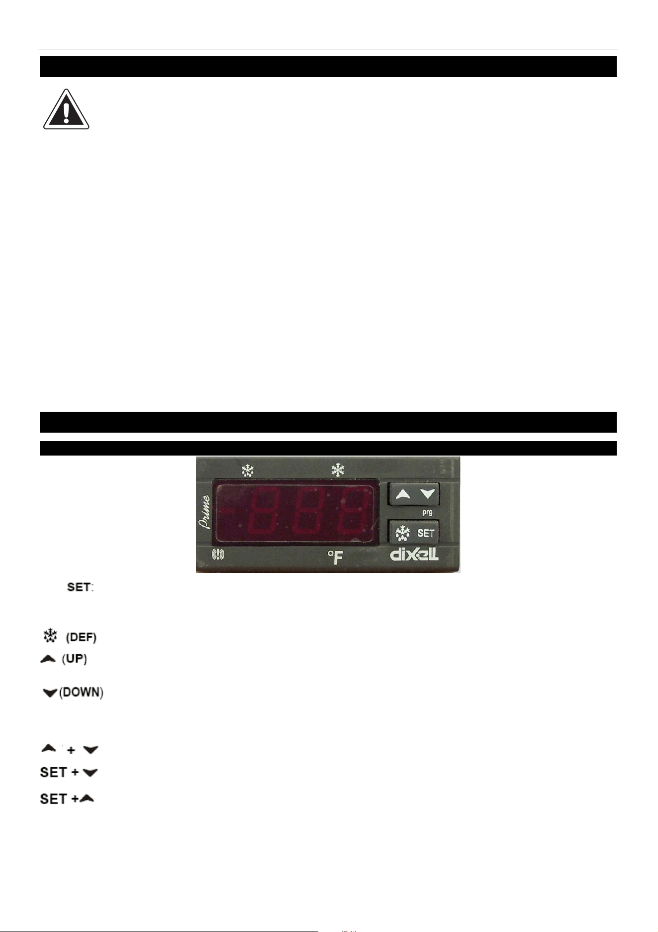
1. FRONT PANEL COMMANDS
To display target set point; in programming mode it selects a parameter or confirms an
operation.
To start a manual defrost
To view the last alarm occurrence; in programming mode, it browses the parameter
codes or increases the display value
To view the last alarm occurrence; in programming mode, it browses the parameter
codes or decreases the display value
KEY COMBINATION
To lock & unlock the keyboard
To enter in programming mode
To return to the room temperature display
CAUTION
Service and Installation Manual
8
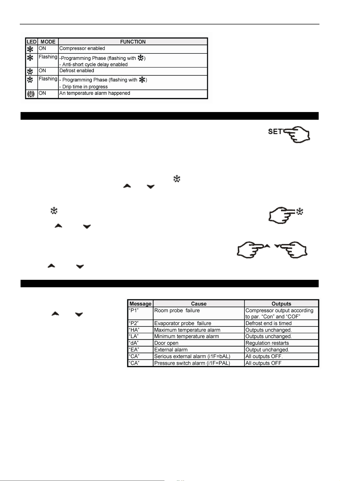
1.1 Function of LEDS
2. MAIN
FUNCTIONS
2.1 HOW TO SEE THE SETPOINT
1. Push and immediately release the SET key: the display will show the set point value.
2. Push and immediately release the SET key or wait for 5 seconds to display the
sensor value again.
2.2 HOW TO CHANGE THE SETPOINT
1. Push the SET key for more than 2 seconds to change the set point value.
2. The value of the set point will be displayed and the LED starts blinking.
3. To change the set value push the or key within 10s.
4. To set new point value, push the SET key again or wait 10s.
2.3 HOW TO START A MANUAL DEFFROST
Push the key for more than 2 seconds and a manual defrost will start
2.4 HOW TO LOCK THE KEYBOARD
1. Hold the and keys for more than 3s.
2. The “POF” message will be displayed and the keyboard will be locked. At this point, it will be possible only
to see the set point or the MAX or Min temperature stored.
3. If a key is pressed more than 3s the ”POF” message will be displayed.
2.5 HOW TO UNLOCK THE KEYBOARD
Hold the and keys together for more than 3s, till the “POF” message is displayed.
3. ALARM SIGNALS
HOW TO SEE THE ALARM AND
RESET THE RECORDED ALARM
1. Hold the or key to
display the alarm signals.
2. When the signal is displayed, hold
the SET key until the “rst” message
is displayed. Push the SET key
again. The “rst” message will start
blinking and the normal temperature
will be displayed again.
Service and Installation Manual
9
MAINTENANCE
The power switch must be turned OFF and the unit disconnected from the power source
whenever performing service, maintenance functions or cleaning the refrigerated area.
Cleaning the Condenser Coil
The condenser coil requires regular cleaning. Cleaning is recommended every 90 days. In some instances,
you may find that there is a large amount of debris and dust or grease accumulated prior to the 90 day time
frame. In these cases the condenser coil should be cleaned every 30 days.
If the build up on the coil consists of only light dust and debris, the condenser coil can be cleaned with a
simple brush. Heavier dust build-up may require a vacuum or even compressed air to blow through the
condenser coil.
If heavy grease is present, there are de-greasing agents available for refrigeration use and specifically for
the condenser coils. The condenser coil may require cleaning with the de-greasing agent and then blown
through with compressed air.
Failure to maintain a clean condenser coil can initially cause high temperatures and excessive run times.
Continuous operation with dirty or clogged condenser coils can result in compressor failures. Neglecting the
condenser coil cleaning procedures will void any warranties associated with the compressor or cost to
replace the compressor.
Never use a high pressure water wash for this cleaning procedure as water can damage
the electrical components located near or at the condenser coil.
In order to maintain proper refrigeration performance, the condenser fins must be cleaned of dust, dirt and
grease regularly. It is recommended that this be done at least every three months. If conditions are such that
the condenser is totally blocked in three months, the frequency of cleaning should be increased. Clean the
condenser with a vacuum cleaner or stiff brush. If extremely dirty, a commercial-grade condenser cleaner
may be required.
Stainless Steel Care and Cleaning
To prevent discoloration of rust on stainless steel, several important steps need to be taken. First, we need
to understand the properties of stainless steel. Stainless steel contains 70-80% iron which will rust. It also
contains 12-30% chromium which forms an invisible passive film over the steels surface which acts as a
shield against corrosion. As long as the protective layer is intact, the metal is still stainless. If the film is
broken or contaminated, outside elements can begin to breakdown the steel and begin to form rust of
discoloration. Proper cleaning of stainless steel requires soft cloths or plastic scouring pads,
NEVER USE STEEL PADS, WIRE BRUSHES OR SCRAPERS!
DANGER
DANGER
DANGER
Service and Installation Manual
10
MAINTENANCE
Cleaning solutions need to be alkaline based or non-chloride based. Any cleaner containing chlorides will
damage the protective film of the stainless steel. Chlorides are commonly found in hard water, salts, and
household and industrial cleaners. If cleaners containing chlorides are used, be sure to rinse and dry
thoroughly.
Routine cleaning of stainless steel can be done with soap and water. Extreme stains or grease should be
cleaned with a non-abrasive cleaner and plastic scrub pad. It is always good to rub with the grain of the steel.
There are also stainless steel cleaners available which can restore and preserve the finish of the steels
protective layer.
Early signs of stainless steel breakdown can consist of small pits and cracks. If this has begun, clean
thoroughly and start to apply stainless steel cleaners in attempt to restore the passivity of the steel.
Never use an acid based cleaning solution!
!!
!Many food products have an acidic content
which can deteriorate the finish. Be sure to clean the stainless steel surfaces of ALL
food products.
Gasket Maintenance
Gaskets require regular cleaning to prevent mold and mildew build up and also to keep the elasticity of
the gasket. Gasket cleaning can be done with the use of warm soapy water. Avoid full strength
cleaning products on gaskets as this can cause them to become brittle and prevent proper seals. Do not
use sharp tools or knives to scrape or clean the gasket which could possibly tear the gasket and rip the
bellows.
Gaskets can easily be replaced and don’t require the use of tools or authorized service technicians. The
gaskets are "Dart" style and can be pulled out of the grove in the door and replaced by pressing the new one
back into place.
Doors/Hinges
Over time and with heavy use, door hinges may become loose. If the door is beginning to sag, tighten
the screws that mount the hinge brackets to the frame of the unit. If the doors are loose or sagging this
can cause the hinge to pull out of the frame which may damage to both the doors and the door hinges.
Drain Maintenance
Each unit has a drain located inside the unit which removes the condensation from the evaporator coil and
evaporates it into an external condensate evaporator pan. Each drain can become loose or disconnected
from moving or bumping the drain. If you notice excessive water accumulation on the inside of the unit, be
sure the drain tube is connected from the evaporator housing to the condensate evaporator drain pan. If
water starts to collect underneath the unit, you may want to check the condensate evaporator drain tube to
be sure it is still located inside the drain pan. The leveling of the unit is important as the units are designed to
drain properly when on a level surface. If your floor is not level this can also cause drain problems. Be sure
all drain lines are free of obstructions because this may cause water to back up and overflow the drain pans.
CAUTION
Service and Installation Manual
11
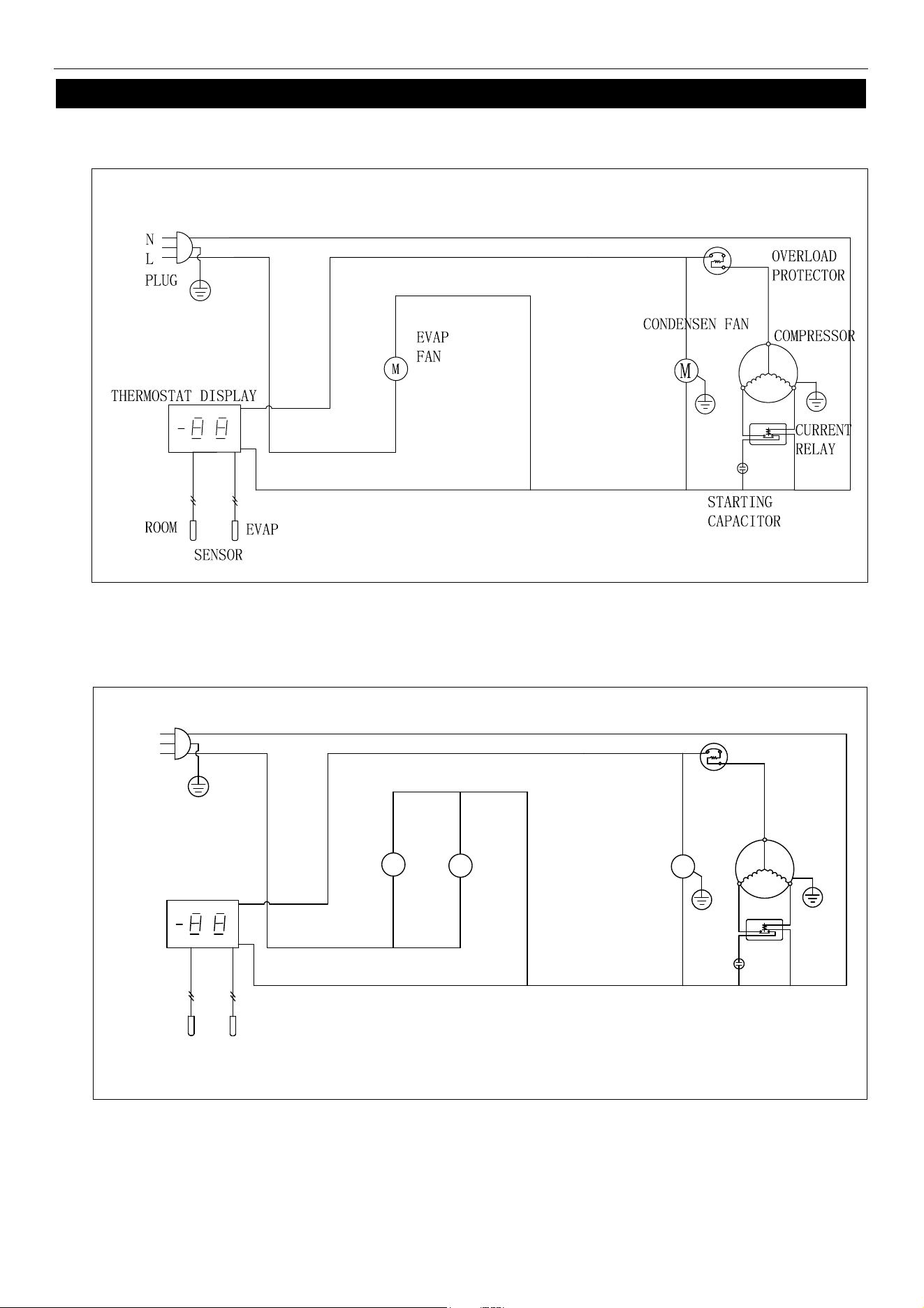
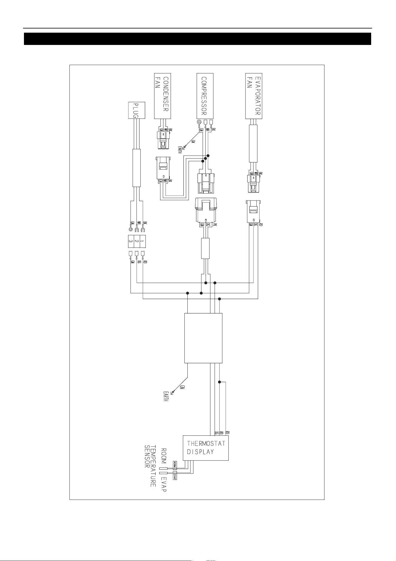
WIRING DIAGRAM
MODEL: ARCB36Z/ARCB36CZ
MODEL:
ARCB
48Z/ARCB60Z/ARCB72Z/ARCB48CZ/ARCB60CZ/ARCB72CZ
PLUG
THERMOSTAT DISPLAY
ROOM
EVAP
SENSOR
CONDENSEN FAN
STARTING
CAPACITOR
CURRENT
RELAY
COMPRESSOR
OVERLOAD
PROTECTOR
M
EVAP
FAN
M
L
N
M
Service and Installation Manual
12
WIRING DIAGRAM
MODEL: ARCB36Z/ARCB48Z/ARCB60Z/ARCB72Z/ARCB36CZ/ARCB48CZ/ARCB60CZ/ARCB72CZ
Two-year parts & labor warranty*
Arctic Air warrants, to the original purchaser, all qualifying models of its new equipment to be free from defects in
material or workmanship, under normal use and maintenance service, for a period of two (2) years from the date of
original purchase or 30 months after shipment date from the manufacturer, whichever occurs first. Warranty coverage
is limited to the repair and/or replacement, including labor charges, of defective parts and/or assemblies. The labor
warranty shall include straight time labor charges and travel charges within 100 miles roundtrip.
* Exclusions
:
Any Arctic Air model installed in mobile application such as concession trailers, food trucks, etc. or in an outdoor
venue shall be limited to one (1) year parts, labor, & compressor warranty only.
Models AWR25, AWF25, ACP40, ACP55, ACP4SQ, & ACPSQ are limited to one (1) year parts & labor coverage.
Light bulbs and door gaskets are limited to 90-day warranty period & door hinges to one (1) year period.
Additional three-year compressor warranty*
In addition to the two (2) year warranty stated above, Arctic Air warrants its compressor units to be free from defects in
both material and workmanship under normal and proper use and maintenance service for a period of three (3)
additional years from the date of original installation but not to exceed five (5) years and three (3) months after
shipment from Arctic Air.
The three (3) year extended compressor warranty applies only to the compressor part itself and does not apply to any
other parts, components, or labor charges involved in replacement of compressor. In addition, shipping charges for
replacement compressors in the extended three-year period are not covered by this warranty and compressor
replacement is limited to one (1) compressor during the three-year period.
*(Not applicable for ACP counter-top models and/or any model being used in mobile/outdoor use application)
Conditions
All service under this warranty, for either labor or parts, must be performed by a preferred service provider arranged
by the Arctic Air Warranty Center at 1-855-431-5558. Proof of purchase will be required to validate warranty
coverage dates. Service coverage is limited to units located in the United States and Canada only.
Limitations & Exclusive Warranty
This parts and labor warranty is the sole and exclusive warranty remedy offered by Arctic Air. Arctic Air’s sole obligation
under this warranty is limited to either repair or replacement of parts and is subject to the limitations listed below.
Arctic Air will bear no responsibility or liability for any equipment which has been misapplied, mishandled,misused,
subjected to harsh chemical action, or external causes such as the use of extension cords, electrical power fluctuations,
lack of proper maintenance, non-factory approved revisions or modifications, or equipment damaged by fire, flood, or
other acts of God.
1. Arctic Air will bear no responsibility for consequential loss or damages such as, including but not limited to,
economic loss, profit loss, personal injury, property damage, damage during transit, losses or damages arising
from food or product spoilage claims.
2. Arctic Air shall bear no responsibility for parts or labor coverage for component failure or other damages
resulting from improper usage, installation, or maintenance as described in the owner’s manual. In addition,
charges that include but are not limited to ferry charges, city torch/burn permits, or labor time to access mobile
units are not covered by this warranty.
3. Arctic Air equipment is intended for commercial use only and this warranty is void if the equipment is installed
in other than commercial applications.
4. All other warranties, either express or implied, arising under law or equity or custom of the trade, including but
not limited to, warranties or merchantability or fitness for a particular purpose are excluded.
Service and Installation Manual
13


Broich Enterprises, Inc. / Arctic Air
7550.Market Place Drive
Eden Prairie, MN 55344
Phone: 952-941-2270
Fax: 952-941-3066
Website: www.arcticairco.com
105010991 V1 20210812