Package Contents .................................................................................................................................. 3
Safety Information .....................................................................................................................……...... 4
Product Overview .....................................................................................................................………... 6
Operating Instruction ........................................................................................................................... 9
Care and Maintenance .....................................................................................................................… 11
Warranty .....................................................................................................................………………. 12
TABLE OF CONTENTS
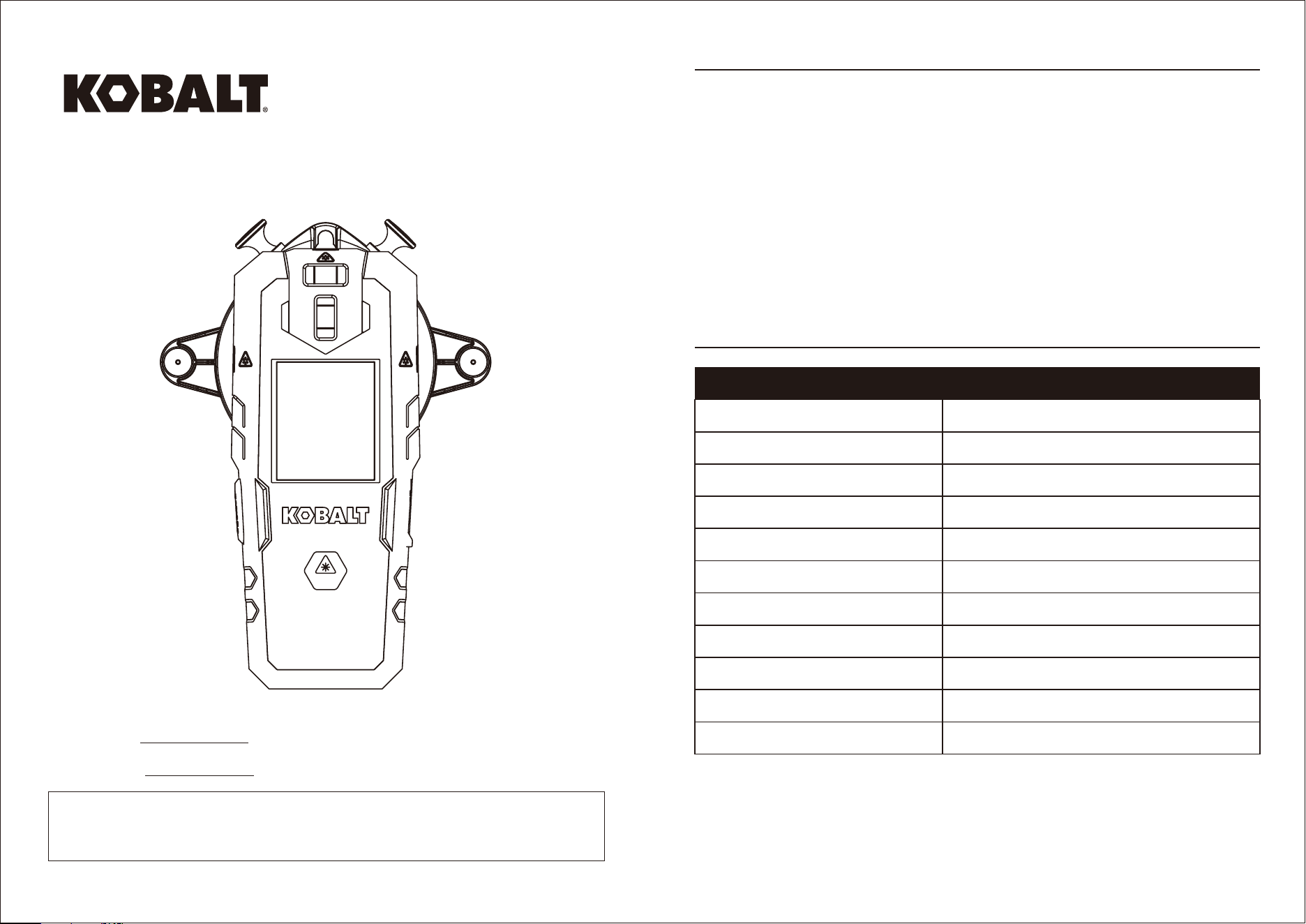
PRODUCT SPECIFICATIONS
Laser λ=630-640nm, Class 2 laser, maximum laser output<1mW
Operating range (typically) 30ft (under 100LUX indoor environment)
Accuracy (typically) ±3/8 in at 30 ft
Depth detection Up to 3/4in (wood or metal studs)
Estimated battery life >10h (Lithium-ion battery)
Operating temperature 32ºF to 104ºF (0ºC to 40ºC)
Operating humidity 10% - 80% RH
Storage temperature 14ºF to 140ºF (-10ºC to 60ºC)
Storage humidity ≤80% RH
Batteries 3.7V rechargeable Lithium-ion battery
Battery capacity 1200 mAh
*Important: The accuracy is rated within distance of 10 meters. Under unfavorable conditions, such as
in extreme interior illumination, transparent surfaces (eg. glass, water), porous surfaces (eg.
insulation materials) or reflecting surfaces (eg. polished metal, glass) or very rough surfaces (eg.
rough cast, natural stone), the tool’s measuring range and accuracy will be reduced.
ON
KOBALT and logo design are
trademarks or registered trademarks of LF,
LLC. All rights reserved.
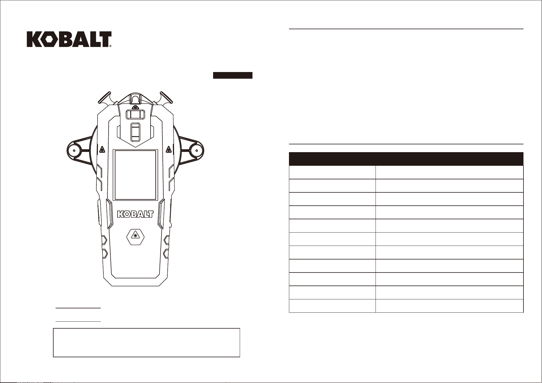
RECHARGEABLE 2-IN-1
LASER LEVEL WITH
STUD FINDER
ITEM #1098165
MODEL #54558
Español p.12
Serial Number
Purchase Date
SS23707
1 2
Thank you for purchasing this Kobalt product.
Questions, problems or missing parts?
Before returning, contact us on:
888-356-2258, 8 a.m - 8 p.m., EST, Monday - Sunday or [email protected].
SPECIFICATIONS
PACKAGE CONTENTS SAFETY INFORMATION
Please read and understand this entire manual before attempting to assemble, operate or install the
product.
WARNING
CAUTION
• LASER RADIATION. Do not stare into beam. Class II laser product. Turn the laser beam on only
when using this tool.
• Do not remove or deface any product labels.
• Avoid direct eye exposure. The laser beam can cause persons being blinded.
• Do not operate the tool around children or allow children to operate the tool.
• Do not place the tool in a position that may cause anyone to stare at the laser beam, whether
intentionally or unintentionally.
• Do not use on reflecting surfaces such as sheet steel, glass or polished metal etc. that have shiny,
reflective surfaces. The shiny surface could reflect the beam back at the operator.
• Always turn the laser tool off when not in use. Leaving the tool on increases the risk of someone
inadvertently staring into the laser beam
• Do not attempt to modify the performance of this laser device in any way. This may result in a
dangerous exposure to laser radiation.
• Do not attempt to repair or disassemble the laser-measuring tool. If unqualified persons attempt to
repair this product, serious injury may occur. Any repair required on this laser product should be
performed only by qualified service personnel.
• Use of other accessories that have been designed for use with other laser tools could result in serious
injury.
• Do not operate the tool outdoors.
• Do not place or store tool under extreme temperature conditions.
• Do not operate the tool in explosive environments, such as in the presence of flammable liquids,
gases or dusts. Sparks can be created in the tool which may ignite the dust or fumes.
• Keep the tool away from cardiac pacemakers. The magnet inside the tool generates a field that can
impair the function of cardiac pacemakers.
• Keep the tool away from magnetic data medium and magnetically-sensitive equipment. The effect of
the magnetic can lead to irreversible data loss.
• Measurement may not be accurate if used beyond the rated range of the device.
• The use of optical instruments with this product will increase eye hazard.
• Always make sure any bystanders nearby aware of the dangers of looking directly into the measuring
tool.
• Do not use the laser viewing glasses as safety goggles, they do not protect eyes against laser
radiation.
ON
• The use of operating or adjusting equipment or the application or processing methods other than
those mentioned herein, can lead to hazardous radiation exposure.
• The batteries must not be disposed with household waste. Care for the environment and take them to
the collection points provided in accordance with national or local regulations. Dispose of the product
appropriately in accordance with the national regulations in force in your country. Adhere to the
national and country specific regulations.
3 4
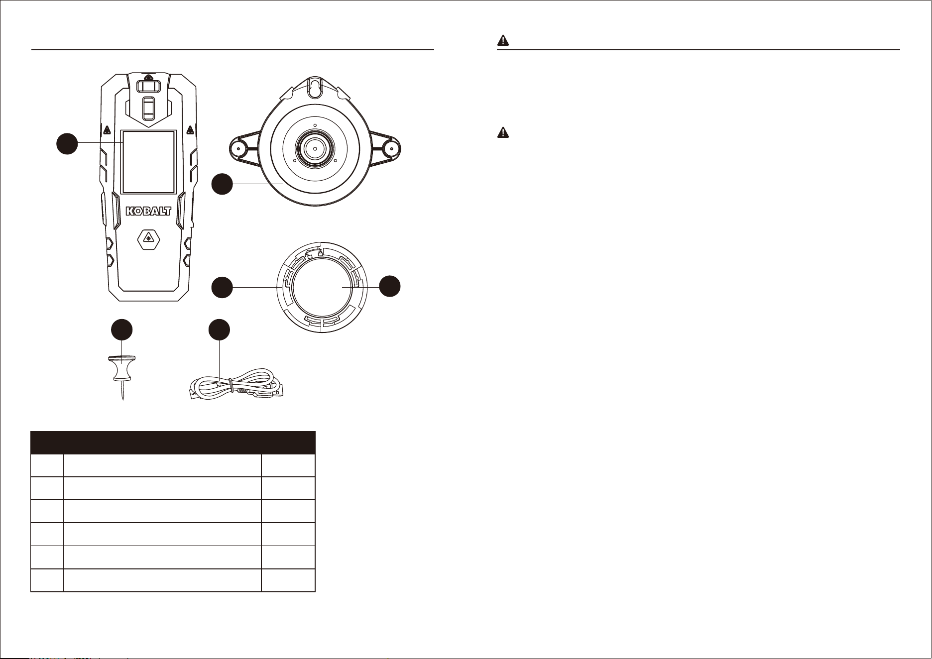
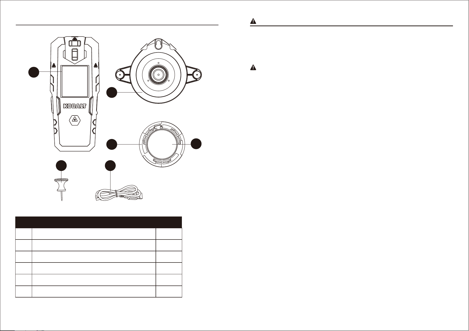
A Rechargeable 2-in-1 laser level with stud finder 1
B Wall mount bracket 1
C Bracket accessory 1
D Reusable double sided mounting gel pad 1
E Push pins 2
F Type-C cable wire 1
A
B
C
E F
D
PART DESCRIPTION QUANTITY
• Working safely with the electronical tool is possible only when the operating and safety information
are read completely and instructions contained herein are strictly followed.
• Never make warning labels on the measuring tool unrecognizable. Save these instructions.
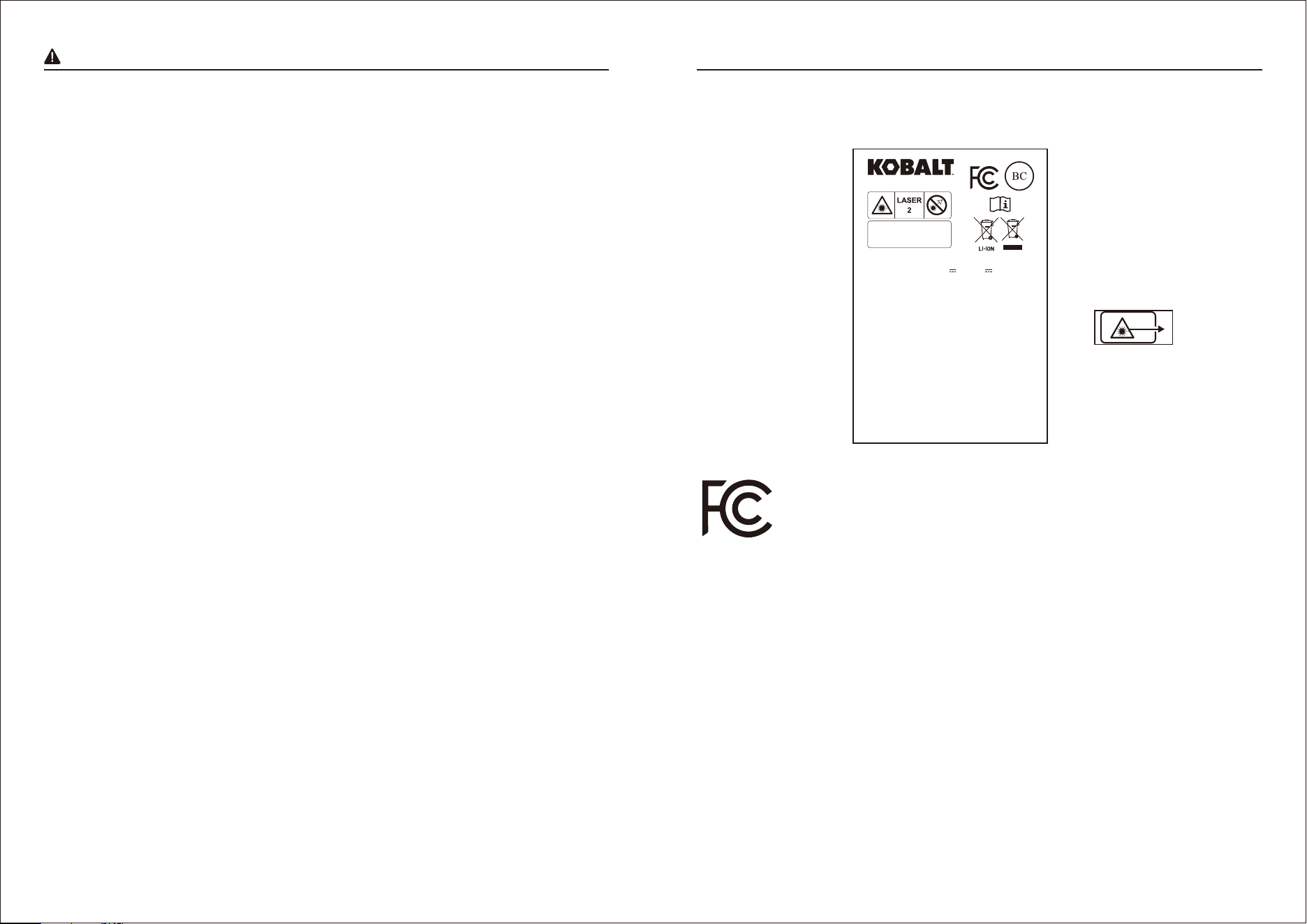
This device complies with part 15 of the FCC Rules.
Operation is subject to the following two conditions:
(1) This device may not cause harmful interference, and
(2) this device must accept any interference received, including interference that may cause undesired
operation.
NOTE: This equipment has been tested and found to comply with the limits for a Class B digital
device, pursuant to part 15 of the FCC Rules. These limits are designed to provide reasonable
protection against harmful interference in a residential installation. This equipment generates, uses
and can radiate radio frequency energy and, if not installed and used in accordance with the instruc-
tions, may cause harmful interference to radio communications. However, there is no guarantee that
interference will not occur in a particular installation. If this equipment does cause
harmful interference to radio or television reception, which can be determined by turning the
equipment off and on, the user is encouraged to try to correct the interference by one or more of the
following measures:
- Reorient or relocate the receiving antenna.
- Increase the separation between the equipment and receiver.
- Connect the equipment into an outlet on a circuit different from that to which the receiver is connected.
- Consult the dealer or an experienced radio/TV technician for help.
CAUTION FOR STUD FINDER
• Material thickness, type of material, moisture content, and other variables can affect sensing results.
The sensor may detect electric wiring or pipes in the same manner that studs are detected depending
on their location to the wall surface.
HELPFUL HINTS FOR STUD FINDER
• This product is only used on drywalls, can not be used for wood wall, brick wall, concrete wall, glass
wall, tile wall, etc.
• Ensure that there is no electrostatic, high-frequency, and electric field interference around.
• Ensure that there is no conductive layer or metallic shielding layer on the surface or inside of the
detected wall. Ensure wallpaper containing no metallic foils or fibers.Generally, surfaces covered with
regular wallpaper or fabric will scan with no difference in function.
• From the beginning of calibration to the end of detection, the gesture holding the tool remains
unchanged, and the force does not change greatly.
• Walls that are freshly painted and are still damp which will affect sensing results.
• When using unit over a stucco wall, place a piece of cardboard over the surface to help provide a
smooth motion across the wall.
• Avoid materials which have inconsistent density such as: carpeting and padding, ceramic floor tile.
• Plaster and lath can not be too excessively thick.
• Diameter of the metal stud to be detected is not less than 5inches(120mm).
• Ensure the wires to be detected are live wires.
• Ensure the wires to be detected are powered by alternating current(AC Wire).
• Ensure the wires to be detected are not shielded by metallic.
5 6
SAFETY INFORMATION PRODUCT OVERVIEW
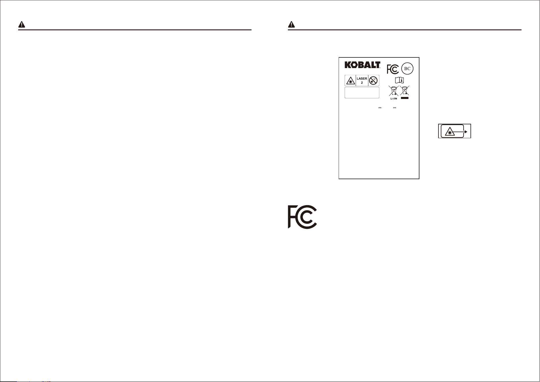
Maximum output < 1mW
Wavelength 630-640nm
IEC 60825-1:2014
Model#: 54558 Date of manufacture: 2023-11
Capacity: 1200mAh [4.44Wh) 3.7V Input: 5V 2000mA
Complies with 21 CFR 1040.10 and 1040.11 except for conformance
with IEC 60825-1 Ed. 3., as described in Laser Notice No.56, dated
May 8, 2019.
This device complies with part 15 of the FCC Rules.
Operation is subject to the following two conditions:
(1) This device may not cause harmful interference, and (2) this
device must accept any interference received, including interference
that may cause undesired operation.
STUD DETECTION
1) Hold unit straight up and down and place flat against wall.
2) Press in and hold the DETECTOR button.
3) Wait for the READY message on LCD screen and two LED lights turn
green.
4) Slide unit slowly across surface of wall without lifting or tilting,
When the left or right LED light turn red, slow down and keep sliding
until CENTER message appears, beep sounds and another LED turns
red.
5) At the same time, the top laser line beam also be projected on the
wall and indicate the center of stud.
AC WIRE DETECTION
Only live AC wires can be detected, AC voltage detection feature works
continually when detecting studs. Once AC voltage detected AC wire
indicator icon will appear. (See instruction manual)
Use caution when drilling, nailing or cutting into walls, floors and ceilings which may contain electrical
wiring or pipes.These items may be detected by the sensor in the same manner in which studs are
detected. Because studs are normally spaced 16inches(406mm) or 24inches(610mm) apart and are
usually 1-1/2inches(38mm) wide, beware of anything closer together or of a different width. Doors
and windows are constructed with studs and headers which are closer together.
• Occasionally, pipes and electrical wiring may not be detected by this product. Observe caution when
cutting or drilling into areas that may contain concealed pipes or wiring. The sensor will not detect live
wires inside metal pipe or metal conduit, behind metallic wall covering, or behind some plywood or
other dense materials. Use caution if area has plywood, thick wood backing behind drywall, or thicker
than normal walls.
• Always turn off the power when working near electrical wires, electric shock may result.
DISPLAY
ON
CALIBRATING...
READY
LASER
CENTER
ON
C
F
E
D
F
F
H
G
JI
A
B
B
C
D
E
F
A
G
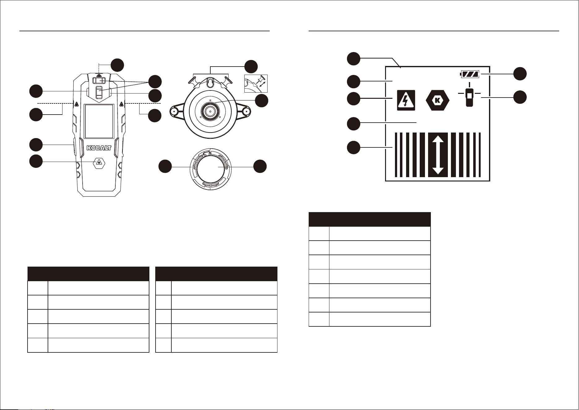
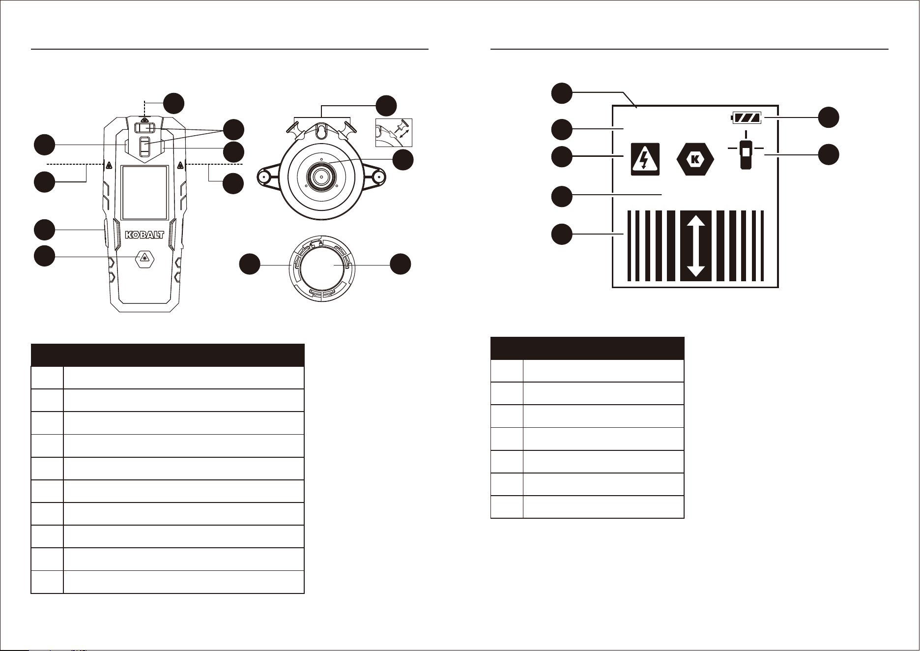
A Detector On/Off button
B Laser On/Off/Mode switch button
C Left LED light
D Right LED light
E Two bubble vial
PART DESCRIPTION
F Laser lines
G Wall mount bracket
H Two push pins
I Bracket accessory
J Reusable double sided mounting gel pad
PART DESCRIPTION
A Battery indicator
B Detector calibrating indicator
C Detector ready indicator
D Live AC wires indicator
E Center of stud indicator
F Stud detection bars
G Laser line indicator
PART DESCRIPTION
PRODUCT OVERVIEW
7 8
PRODUCT OVERVIEW
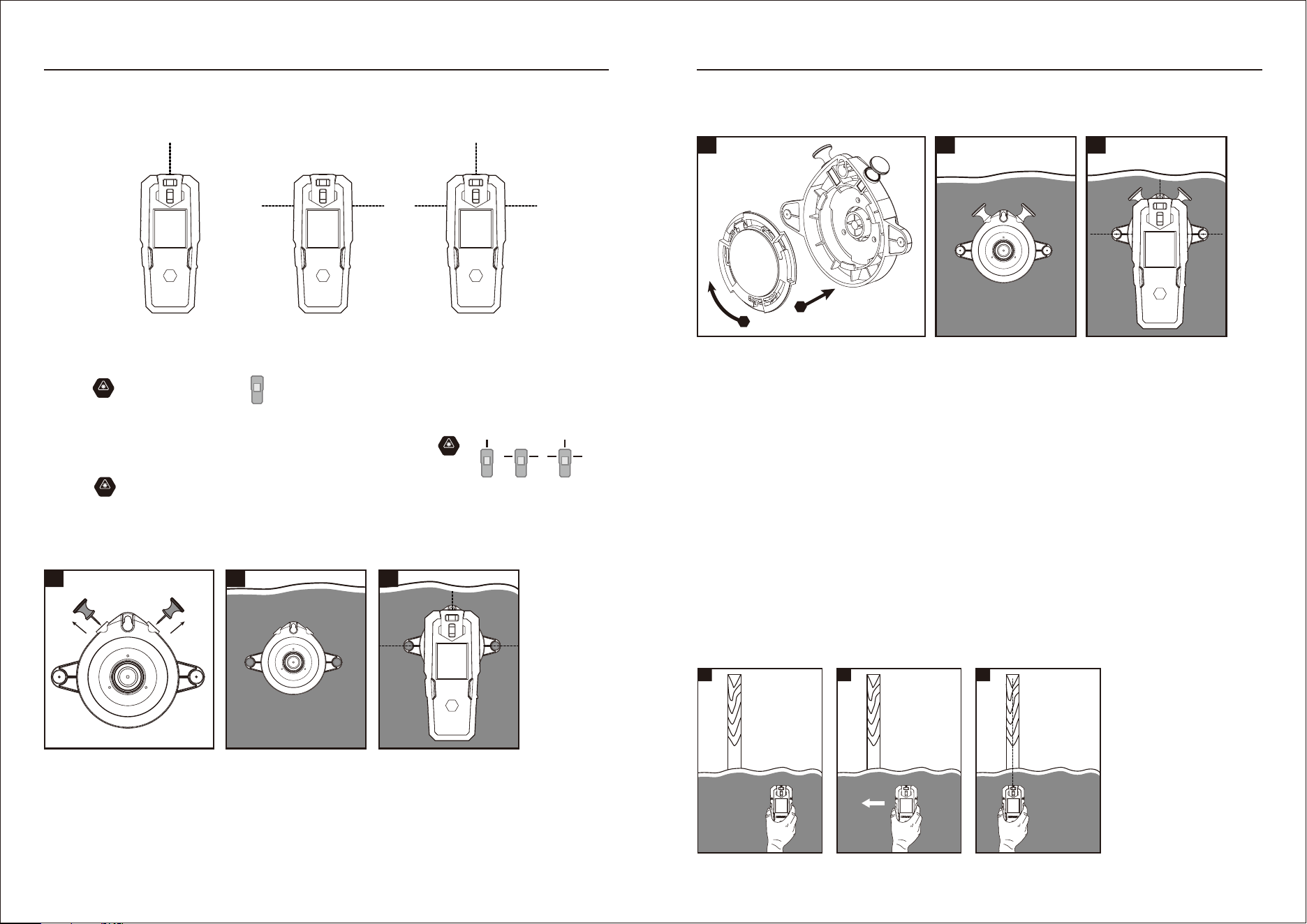
LASER LINES
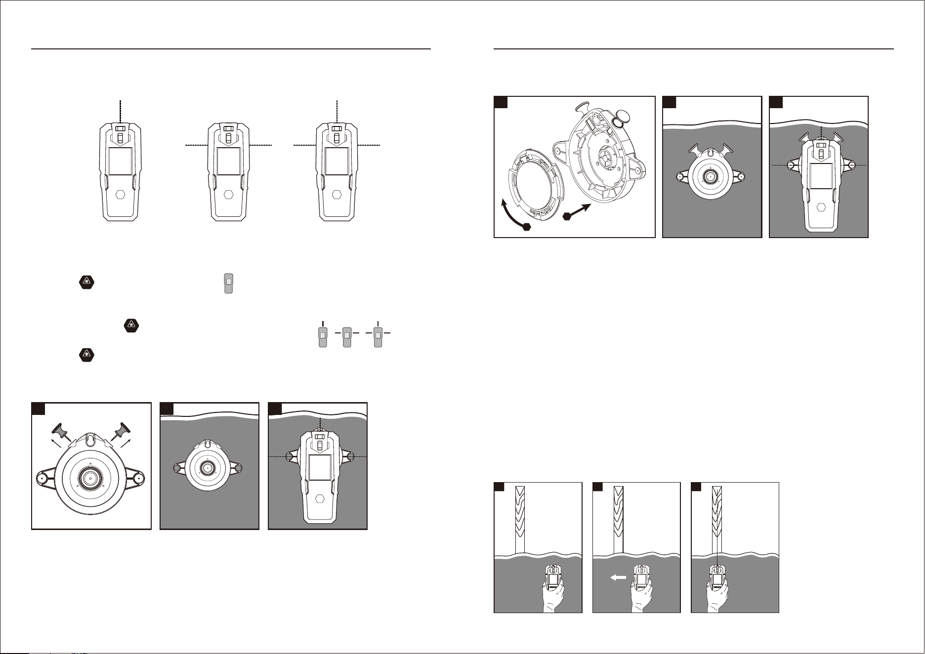
Turning ON/OFF/mode switch.
Mounting with the push pins
(For securing the laser level on drywall surface only)
ON
ON
ON
Horizontal Line ModeVertical Line Mode
Horizontal & Vertical
Line Modes
1) Press button for 1.5 seconds, will appear on the LCD screen.
2) Three operating modes (vertical line mode,horizontal line mode, horizontal & vertical line modes)
can be switched in-between at any time by short pressing the button .
The Laser line indicator on the LCD screen also will be switched between
3) Press button for 1.5 seconds to turn off the laser line.
1) Remove the push pins from the storage area.
2) Insert a push pin into each hole on the sides of the bracket and push the pins into the mounting.
3) Place the laser level onto the bracket and use the bubble levels to level the unit.
1 2 3
9 10
OPERATING INSTRUCTION
DETECTOR
Stud detection
Mounting with the reusable double sided gel pad
(For mounting to glass, metal, marble, tile, plastic, and other smooth surfaces. Do not use on drywall.)
1) Install the bracket accessory on the back of bracket and remove the release liner of gel pad.
2) Stick the bracket on the the desired surface.
3) Place the laser level onto the bracket and use the bubble levels to level the unit.
Note:
• The gel pad may be washed and used repeatedly. To maintain good adhesion, wash the gel pad
frequently. Make sure the gel pad is cleaned of any dust or debris before your operation.
• Do not use the gel pad to fasten onto the wall if the wall surface is loose or wet.
• Always keep the target wall surface clean.
• Remove from the wall slowly after using, any residue of the gel pad remaining on the wall can be
cleaned by rolling the gel pad over the residue.
• Both side of bracket accessory all can be installed on the back of bracket, when one side with gel pad
not be used, can keep this side be installed interiorly for gel pad is cleaned.
Detecting elements for wood and metal studs and AC wire are located in the lower part of the unit.
For stud detection through up to 3/4 inch (19mm) thick drywall.
1
1
ON
2
ON
3
ON
1
2
2 3
OPERATING INSTRUCTION
• Avoid exposing the tool to shock, continuous vibration or extreme hot or cold environment.
• Always store the tool indoors.
• Always keep the tool free of dust and liquids. Use only a clean soft cloth for cleaning. If necessary,
slightly moisten the cloths with pure alcohol or a little water.
• Do not disassemble the tool, this will expose the user to hazardous radiation exposure.
• Do not attempt to change any part of the tool.
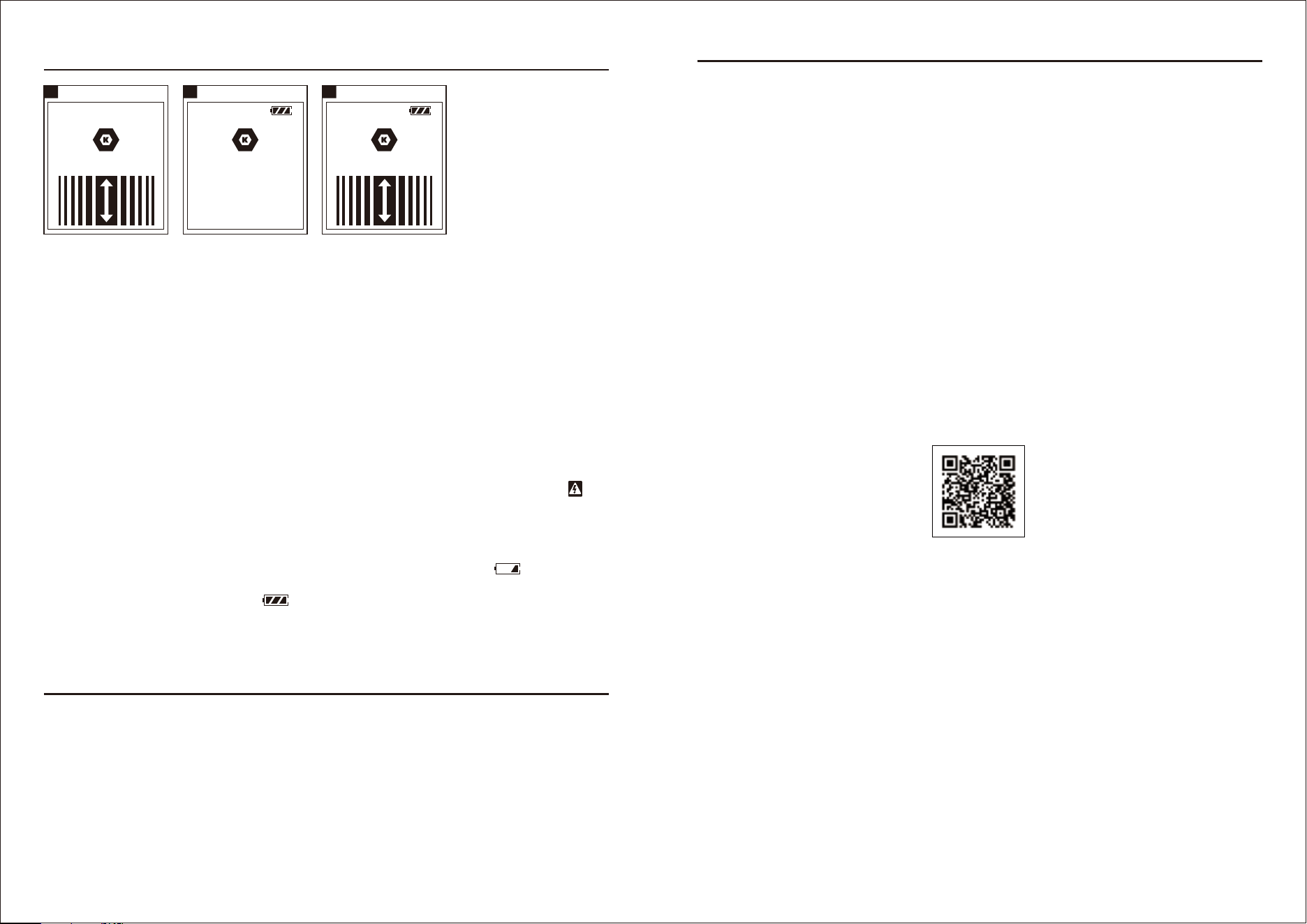
READY
CALIBRATING...
AC Wire Sensing
4 5
READY
CENTER
6
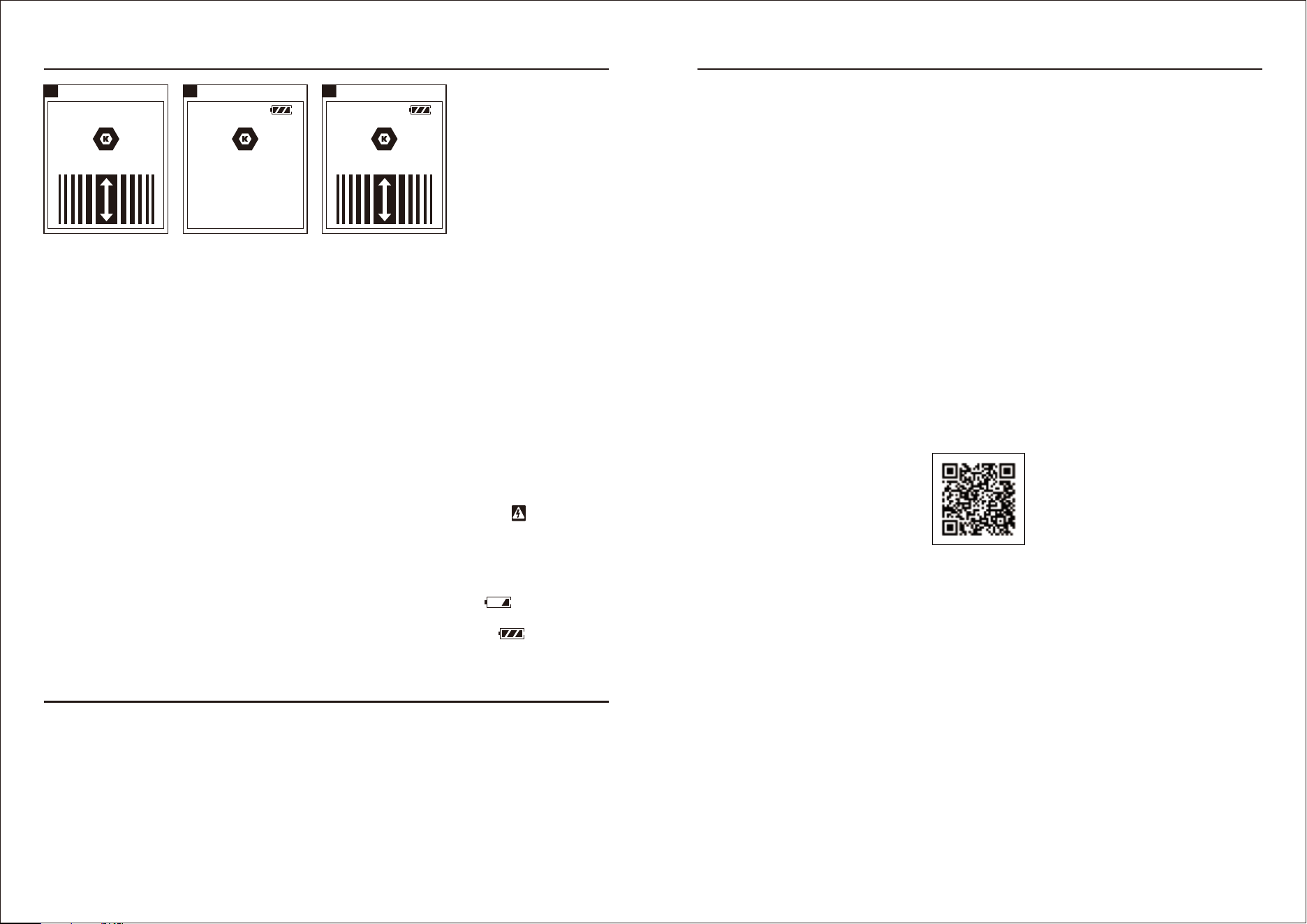
1) Hold unit straight up and down and place flat against wall (Picture 1)
2) Press in and hold DETECTOR button. LCD screen (Picture 4) will light and detector will run
initialization process.
3) READY message will appear on LCD screen (Picture 5), two LED lights will turn green and the unit
will beep once to indicate it is calibrated and ready for detection.
4) Slide unit slowly (Picture 2), horizontally across surface of wall without lifting or tilting. When the left
or right LED light turn red, slow down and keep sliding until CENTER message appears (Picture 6),
beep sounds and another LED turns red.
5) At the same time, the top laser line beam also be projected on the wall and indicate the center of
stud (Picture 3).
Test on a known "live" AC wire before each use. For AC Detection up to 1-1/2 inches (38mm) from the
surface. The sensor detects AC voltage and will identify only live wires. AC voltage detection feature
works continuously when detecting studs. It assists in identifying when the sensor is near live AC
wiring and detector button is depressed. Once AC voltage has been detected AC wire indicator
will appear on the LCD screen. If the unit is calibrated close to AC wire, it may decrease AC wiring
sensor sensitivity.
CHARGING
1) Connect Type-C cable wire properly to charge the laser level. Battery indicator will flash when
charging.
2) When Battery indicator stop flashing , the charging is completed. Remove Type-C cable wire.
3) The machine will automatically shut off after 30 minutes without any operation.
11
OPERATING INSTRUCTION
CARE AND MAINTENANCE
This product has been designed to be a low-maintenance tool. However, in order to maintain its
performance, you must always follow these simple directions:
12
WARRANTY
For 2 year from the date of purchase, the product is warranted for the original purchaser to be free from
defects in material and workmanship. This guarantee does not cover damage due to abuse, normal
wear, improper maintenance, neglect, unauthorized repair/alteration, or expendable parts and
accessories expected to become unusable after a reasonable period of use.
If you think your product meets the above guarantee criteria, please return it to the place of purchase
with valid proof of purchase and the defective product will be repaired or replaced at no charge. This
guarantee gives you specific legal rights and you may also have other rights that vary from state to
state.
Printed in China
DOWNLOAD YOUR
INSTRUCTION MANUAL
13 14
ON
KOBALT y el diseño del logotipo son
marcas comerciales o marcas registradas de LF,
LLC. Todos los derechos reservados.
NIVEL LÁSER CON
DETECTOR DE VIGAS
RECARGABLE 2 EN 1
ARTÍCULO #1098165
MODELO #54558
SS23707
Contenido del paquete.......................................................................................................................... 15
Información de seguridad..........................................................................................................…….... 16
Descripción general del producto..........................................................................................………..... 19
Instrucciones de funcionamiento .......................................................................................................... 21
Cuidado y mantenimiento ................................................................................................................... 23
Garantía .....................................................................................................................……………….. 24
ÍNDICE
ESPECIFICACIONES DEL PRODUCTO
Láser
Rango de funcionamiento (normalmente) 9.14 m (menos de 100 LUX en ambiente de interior)
Precisión (normalmente) ±3.17 mm a 9.14 m
Detección de profundidad Hasta 19.05 mm (vigas de madera o metal)
Duración estimada de la batería >10 h (batería de iones de litio)
Temperatura de funcionamiento De 0 ºC a 40 ºC (de 32 ºF a 104 ºF)
Humedad de funcionamiento 10% - 80% HR
Temperatura de almacenamiento De -10 ºC a 60 ºC (de 14 ºF a 140 ºF)
Humedad de almacenaje ≤80% HR
Baterías 3,7 V contiene una batería recargable de iones de litio
Capacidad de batería 1200 mAh
*Importante: la precisión se clasifica dentro de una distancia de 10 metros. En condiciones
desfavorables, como en caso de iluminación interior extrema, superficies transparentes (p. ej.,
vidrio, agua), superficies porosas (p. ej., materiales aislantes) o superficies que reflejan (p. ej.,
metal pulido, vidrio) o superficies muy irregulares (p. ej., molde en bruto, piedra natural), se
reducirá el rango de medición y la precisión de la herramienta.
ESPECIFICACIONES
Número de serie
Fecha de compra
Gracias por comprar este producto Kobalt.
¿Preguntas, problemas o piezas faltantes?
Antes de devolver, contáctenos en:
888-356-2258, de lunes a domingo de 8 a.m. a 8 p.m., hora estándar del Este, o [email protected]
λ = 620 nm-690 nm, láser Clase 2,
salida máxima de láser < 1 mW
CONTENIDO DEL PAQUETE
ON
16
A Nivel láser recargable 2 en 1 con detector de vigas 1
B Soporte de montaje de pared 1
C Accesorio de soporte 1
D Almohadillas de gel de montaje reutilizables de doble cara 1
E Remaches 2
F Cable tipo C 1
A
B
C
E F
D
PIEZA DESCRIPCIÓN CANTIDAD
INFORMACIÓN DE SEGURIDAD
Lea y comprenda completamente este manual antes de intentar ensamblar, usar o instalar el
producto.
ADVERTENCIA
PRECAUCIÓN
• RADIACIÓN LÁSER. No mire directamente el rayo. Producto láser Clase II. Encienda el rayo láser
solo al momento de utilizar la herramienta.
• No retire ni dañe ninguna etiqueta del producto.
• Evite la exposición directa a los ojos. El rayo láser puede provocar ceguera en las personas.
• No utilice la herramienta cerca de niños ni permita que la utilicen.
• No coloque la herramienta en una posición que pueda causar que alguien mire directamente el rayo
láser, ya sea intencionalmente o no.
• No utilice la herramienta en superficies que reflejan, como láminas de acero, vidrio o metal pulido,
que tienen superficies brillantes y reflectantes. La superficie brillante puede reflejar el rayo hacia el
operador.
• Siempre apague la herramienta láser cuando no la utilice. Dejar la herramienta encendida aumenta el
riesgo de que alguien mire el láser de forma inadvertida
• No intente modificar el rendimiento de este dispositivo láser de ninguna forma. Esto puede provocar
una exposición peligrosa a la radiación láser.
• No intente reparar ni desensamblar la herramienta de medición láser. Si personas no calificadas
intentan reparar este producto, pueden provocarse lesiones graves. Solo el personal de servicio
calificado puede reparar este producto láser.
• El uso de otros accesorios diseñados para utilizarse con otras herramientas láser puede provocar
lesiones.
• No utilice la herramienta en exteriores.
• No coloque o guarde la herramienta bajo condiciones extremas de temperatura.
• No utilice la herramienta en entornos en los que exista riesgo de explosión, como lugares donde
haya líquidos inflamables, gases o polvos. La herramienta puede producir chispas que podrían
encender el polvo o los gases.
• Mantenga la herramienta lejos de marcapasos cardíacos. El imán que se encuentra dentro de la
herramienta genera un campo que puede perjudicar la función de marcapasos cardíacos.
• Mantenga la herramienta alejada de medios de datos magnéticos y equipos sensibles al magnetis-
mo. Los efectos del magnetismo pueden producir pérdidas de datos irreversibles.
• Es posible que las mediciones no sean precisas al utilizar el dispositivo fuera del rango especificado.
• El uso de instrumentos ópticos con este producto aumentará el riesgo de lesiones en los ojos.
• Siempre asegúrese de que las personas que se encuentran cerca tengan en cuenta los peligros de
mirar directamente a la herramienta herramienta.
• No use las gafas de visión láser como gafas de seguridad ya que no protegen los ojos del láser
• El uso de instrumentos de operación o de ajuste, o de métodos de aplicación o procesamiento
distintos de los mencionados aquí, pueden provocar una exposición a radiación peligrosa.
• Las baterías no se debe desechar en el basurero. Cuide el medio ambiente y llévelos a los puntos de
recolección según las regulaciones nacionales o locales. Deseche el producto adecuadamente
según las regulaciones nacionales vigentes en su país. Cumpla con las regulaciones nacionales y
específicas del país.
• Para trabajar de forma segura con esta herramienta electrónica, debe leer por completo la información
de seguridad y operación, y seguir estrictamente las instrucciones establecidas en este documento.
• Nunca deje que las etiquetas de advertencia de la herramienta de medición queden irreconocibles.
Guarde estas instrucciones.
15
INFORMACIÓN DE SEGURIDAD
17
Este dispositivo cumple con la sección 15 de las Normas de la FCC.
El funcionamiento está sujeto a las siguientes dos condiciones:
(1) Este dispositivo no debe causar interferencia perjudicial y
(2) Este dispositivo deberá aceptar cualquier interferencia recibida, incluida la interferencia que
pudiese causar la operación no deseada.
NOTA: este equipo se probó y se verificó que cumple con los límites para un dispositivo digital de
clase B, conforme a la sección 15 de las reglas de la FCC. Estos límites están diseñados para
proporcionar protección razonable contra interferencias perjudiciales en una instalación residencial.
Este equipo genera, utiliza y puede irradiar energía de radiofrecuencia y, si no se instala ni se usa de
acuerdo con las instrucciones, puede causar interferencias perjudiciales para las comunicaciones de
radio. Sin embargo, no se garantiza que no se producirán interferencias en una instalación en
especial. Si este equipo genera una interferencia perjudicial para la recepción de radio o televisión,
que se puede determinar al encender y apagar el equipo, se recomienda al usuario que intente
corregir la interferencia con una o más de las siguientes medidas:
- Reorientar o reubicar la antena de recepción.
- Aumentar la separación entre el equipo y el receptor.
- Conectar el equipo a un tomacorriente de un circuito distinto al que usa el receptor.
- Solicitar ayuda al distribuidor o a un técnico con experiencia en radio/TV
18
INFORMACIÓN DE SEGURIDAD
Maximum output < 1mW
Wavelength 630-640nm
IEC 60825-1:2014
Model#: 54558 Date of manufacture: 2023-11
Capacity: 1200mAh [4.44Wh) 3.7V Input: 5V 2000mA
Complies with 21 CFR 1040.10 and 1040.11 except for conformance
with IEC 60825-1 Ed. 3., as described in Laser Notice No.56, dated
May 8, 2019.
This device complies with part 15 of the FCC Rules.
Operation is subject to the following two conditions:
(1) This device may not cause harmful interference, and (2) this
device must accept any interference received, including interference
that may cause undesired operation.
STUD DETECTION
1) Hold unit straight up and down and place flat against wall.
2) Press in and hold the DETECTOR button.
3) Wait for the READY message on LCD screen and two LED lights turn
green.
4) Slide unit slowly across surface of wall without lifting or tilting,
When the left or right LED light turn red, slow down and keep sliding
until CENTER message appears, beep sounds and another LED turns
red.
5) At the same time, the top laser line beam also be projected on the
wall and indicate the center of stud.
AC WIRE DETECTION
Only live AC wires can be detected, AC voltage detection feature works
continually when detecting studs. Once AC voltage detected AC wire
indicator icon will appear. (See instruction manual)
PRECAUCIÓN PARA EL DETECTOR DE VIGAS
• El grosor del material, el tipo de material, el contenido de humedad y otras variables pueden afectar
los resultados de la detección. El sensor puede detectar cableado eléctrico o tuberías de la misma
manera que se detectan montantes, según su ubicación en la superficie de la pared. Tenga cuidado
cuando taladre, clave o corte en paredes, pisos o techos que puedan contener un cableado eléctrico
o tuberías. El sensor puede detectar estos elementos de la misma manera en que se detectan los
montantes. Debido a que los montantes normalmente están espaciados a 406.4 mm (16 pulg.) o
609.6 mm (24 pulg.) de distancia y suelen tener 38.1 mm (1 1/2 pulg.) de ancho, tenga cuidado con
cualquier cosa que esté más cerca entre sí o que tenga un ancho diferente. Las puertas y ventanas
se construyen con montantes y cabezales que están más juntos.
• En ocasiones, es posible que este producto no detecte tuberías y cableado eléctrico. Tenga cuidado
al cortar o perforar áreas que puedan contener tuberías o cableado ocultos. El sensor no detectará
cables con corriente dentro de tuberías o conductos de metal, detrás de revestimientos de paredes
metálicos o detrás de madera contrachapada u otros materiales densos. Tenga precaución si el área
tiene madera contrachapada, un refuerzo de madera gruesa detrás de paneles de yeso o si es más
gruesa que las paredes normales.
• Desconecte siempre la alimentación cuando trabaje cerca de cables eléctricos, ya que podría
producirse una descarga eléctrica.
CONSEJOS ÚTILES PARA EL DETECTOR DE VIGAS
• Este producto solo se utiliza en paneles de yeso, no se puede utilizar en paredes de madera, ladrillo,
concreto, vidrio, azulejos, etc.
• Asegúrese de que no haya interferencias electrostáticas, de alta frecuencia o de campos eléctricos
alrededor.
• Asegúrese de que no haya ninguna capa conductora o capa de protección metálica en la superficie o
en el interior de la pared detectada. Asegúrese de que el papel tapiz no contenga láminas ni fibras
metálicas. Generalmente, las superficies cubiertas con papel tapiz o tela normal se escanearán sin
ninguna diferencia en su función.
• Desde el inicio de la calibración hasta el final de la detección, el gesto de sostener la herramienta
permanece inalterado y la fuerza no cambia mucho.
• Las paredes recién pintadas que aún estén húmedas afectarán los resultados de detección.
• Cuando utilice la unidad sobre una pared de estuco, coloque un trozo de cartón sobre la superficie
para ayudar a proporcionar un movimiento suave a lo largo de la pared.
• Evite materiales que tengan una densidad inconsistente como: alfombra y acolchado, piso de
cerámica.
• El yeso y el listón no pueden ser excesivamente gruesos.
• El diámetro del perno metálico que se va a detectar no debe ser inferior a 127 mm (5 pulg.).
• Asegúrese de que los cables que se van a detectar estén activos.
• Asegúrese de que los cables que se van a detectar estén alimentados por corriente alterna (cable de
CA).
• Asegúrese de que los cables que se van a detectar no cuenten con un protector de metal.
ON
C
F
E
D
F
F
H
G
JI
A
B
A Botón de encendido/apagado del detector
B Botón de encendido/apagado/interruptor de modo del láser
C Luz LED izquierda
D Luz LED derecha
E Dos ampollas de burbujas
PIEZA DESCRIPCIÓN
F Líneas láser
G Soporte de montaje de pared
H Dos remaches
I Accesorio de soporte
J Almohadillas de gel de montaje reutilizables de doble cara
DESCRIPCIÓN GENERAL DEL PRODUCTO
19 20
PANTALLA
CALIBRATING...
READY
LASER
CENTER
ON
B
C
D
E
F
A Indicador de la batería
B Indicador de calibración del detector
C Indicador de detector listo
D Indicador de cableados de CA activos
E Indicador del centro de la viga
F Barras de detección de vigas
G Indicador de línea láser
PIEZA DESCRIPCIÓN
DESCRIPCIÓN GENERAL DEL PRODUCTO
A
G
21 22
LÍNEAS LÁSER
Encendido/apagado/interruptor de modo.
Montaje con remaches
(Solo para asegurar el nivel láser en una superficie de paneles de yeso)
ON
ON
ON
Modo de línea horizontalModo de línea vertical
Modos de línea
horizontal y vertical
1) Presione el botón durante 1,5 segundos, aparecerá en la pantalla LCD.
2) Se pueden cambiar tres modos de funcionamiento (modo de línea vertical, modo de línea
horizontal, modos de línea horizontal y vertical) en cualquier momento presionando
brevemente el botón .
El indicador de línea láser en la pantalla LCD también cambiará entre
3) Presione el botón durante 1,5 segundos para apagar la línea láser.
1) Retire los remaches del área de almacenamiento.
2) Inserte un remache en cada orificio a los costados del soporte e inserte los remaches en el de
montaje.
3) Coloque el nivel láser sobre el soporte y use los niveles de burbuja para nivelar la unidad.
1 2 3
INSTRUCCIONES DE FUNCIONAMIENTO
DETECTOR
Detección de vigas
Montaje con almohadillas de gel reutilizables de doble cara
(Para montaje en vidrio, metal, mármol, azulejos, plástico y otras superficies lisas. No use el producto
en paneles de yeso)
1) Instale el accesorio del soporte en la parte posterior del soporte y retire el revestimiento antiadherente
de las almohadillas de gel.
2) Pegue el soporte en la superficie deseada.
3) Coloque el nivel láser sobre el soporte y use los niveles de burbuja para nivelar la unidad.
Nota:
• Las almohadillas de gel se pueden lavar y utilizar repetidamente. Para mantener una buena adherencia,
lave la almohadilla de gel con frecuencia. Asegúrese de que las almohadillas de gel estén limpias de
polvo o residuos antes de la operación.
• No utilice las almohadillas de gel para fijarlas a la pared si la superficie de la pared está suelta o mojada.
• Mantenga siempre limpia la superficie de la pared objetivo.
• Retírelas de la pared lentamente después del uso; cualquier residuo de las almohadillas de gel que
quede en la pared se puede limpiar pasando las almohadillas de gel sobre el residuo.
• Ambos lados del accesorio del soporte se pueden instalar en la parte posterior del soporte, cuando no
se utiliza un lado con almohadillas de gel, puede dejar ese lado instalado en el interior para limpiar las
almohadillas de gel.
Los elementos de detección de vigas de madera y metal y cableado de CA se encuentran en la parte
inferior de la unidad. Para la detección de vigas a través de paneles de yeso de hasta 19.05 mm (3/4" )
de grosor.
1
1
ON
2
ON
3
ON
1
2
2 3
INSTRUCCIONES DE FUNCIONAMIENTO
• Evite exponer la herramienta a sacudidas, vibraciones continuas, calor extremo o frío extremo.
• Siempre almacene la herramienta en interiores.
• Siempre mantenga la herramienta libre de polvo y líquidos. Solo utilice un paño limpio y suave para
limpiarla. Si es necesario, humedezca ligeramente el paño con alcohol puro o un poco de agua.
• No desarme la herramienta, ya que expondrá al usuario a una radiación peligrosa.
• No intente cambiar ninguna pieza de la herramienta.
READY
CALIBRATING...
Detección de cableado de CA
4 5
READY
CENTER
6
1) Sostenga la unidad hacia arriba y hacia abajo y colóquela plana contra la pared (Imagen 1)
2) Presione y mantenga presionado el botón DETECTOR. La pantalla LCD (Imagen 4) se iluminará y
el detector ejecutará el proceso de inicialización.
3) Aparecerá el mensaje READY (listo) en la pantalla LCD (Imagen 5), dos luces LED se volverán
verdes y la unidad emitirá un pitido para indicar que está calibrada y lista para la detección.
4) Deslice la unidad lentamente (Imagen 2) de forma horizontal por la superficie de la pared sin
levantarla ni inclinarla. Cuando la luz LED izquierda o derecha se vuelve roja, reduzca la velocidad
y siga deslizándola hasta que aparezca el mensaje CENTER (centro) (Imagen 6), suenan pitidos y
otro LED se vuelve rojo.
5) Al mismo tiempo, el rayo de la línea láser superior también se proyectará en la pared e indicará el
centro de la viga (Imagen 3).
Pruebe con un cableado de CA "activo" conocido antes de cada uso. Para detección de CA hasta
3.81 cm (1 1/2") de la superficie. El sensor detecta voltaje de CA e identificará solo cables activos. La
función de detección de voltaje de CA funciona continuamente al detectar vigas. Ayuda a identificar
cuando el sensor está cerca de un cableado de CA con corriente y el botón del detector está
presionado. Una vez que se haya detectado el voltaje de CA, aparecerá el indicador de cable de
CA en la pantalla LCD. Si la unidad se calibra cerca del cableado de CA, puede disminuir la sensibili-
dad del sensor del cableado de CA.
ESTACIÓN
1) Conecte correctamente el cable tipo C para cargar el nivel láser. El indicador de batería
parpadeará durante la carga.
2) Cuando el indicador de batería deja de parpadear significa que la carga finalizó . Retire el
cableado del cable tipo C.
3) La máquina se apagará automáticamente después de 30 minutos sin ninguna operación.
23
INSTRUCCIONES DE FUNCIONAMIENTO
CUIDADO Y MANTENIMIENTO
Este producto se diseñó para tener poco mantenimiento. Sin embargo, para mantener su rendimiento,
siempre debe seguir estas simples instrucciones:
24
GARANTÍA
Este producto tiene cobertura de garantía contra defectos en materiales y mano de obra por 2 años a
partir de la fecha de compra para el comprador original. Esta garantía no cubre daños debidos al mal
uso, desgaste normal, mantenimiento inadecuado, negligencia, reparaciones o alteraciones no
autorizadas o piezas y accesorios prescindibles que se espera que resulten inutilizables después de un
período de uso razonable.
Si cree que este producto cumple con la garantía mencionada anteriormente, devuelva el producto al
lugar donde lo compró con un comprobante de compra válido y el producto defectuoso se reparará o
reemplazará sin cargo. Esta garantía le otorga derechos legales específicos, pero también podría tener
otros derechos que varían según el estado.
Impreso en China
DESCARGUE EL
MANUAL DE INSTRUCCIONES