SPLIT-TYPE AIR CONDITIONERS
English
OPERATING INSTRUCTIONS
For user
• To use this unit correctly and safely, be sure to read these operating
instructions before use.
INDOOR UNIT
MSZ-EF22VGDW MSZ-EF25VGDW MSZ-EF35VGDW MSZ-EF42VGDW MSZ-EF50VGDW
MSZ-EF22VGDB MSZ-EF25VGDB MSZ-EF35VGDB MSZ-EF42VGDB MSZ-EF50VGDB
MSZ-EF22VGDS MSZ-EF25VGDS MSZ-EF35VGDS MSZ-EF42VGDS MSZ-EF50VGDS
MSZ-EF22VGKDW MSZ-EF25VGKDW MSZ-EF35VGKDW MSZ-EF42VGKDW MSZ-EF50VGKDW
MSZ-EF22VGKDB MSZ-EF25VGKDB MSZ-EF35VGKDB MSZ-EF42VGKDB MSZ-EF50VGKDB
MSZ-EF22VGKDS MSZ-EF25VGKDS MSZ-EF35VGKDS MSZ-EF42VGKDS MSZ-EF50VGKDS
En-1
● OPERATING INSTRUCTIONS ●
WARNING
Do not connect the power cord to an intermediate point, use an
extension cord, or connect multiple devices to a single AC outlet.
• Thismaycauseoverheating,re,orelectricshock.
Make sure the power plug is free of dirt and insert it securely into
the outlet.
• Adirtyplugmaycausereorelectricshock.
Do not bundle, pull, damage, or modify the power cord, and do not
apply heat or place heavy objects on it.
• Thismaycausereorelectricshock.
Do not turn the breaker OFF/ON or disconnect/connect the power
plug during operation.
• Thismaycreatesparks,whichcancausere.
• AftertheindoorunitisswitchedOFFwiththeremotecontroller,make
suretoturnthebreakerOFFordisconnectthepowerplug.
• Sincerotatingpartsandpartswhichcouldcauseanelectricshockareused
in this product, be sure to read these “Safety Precautions” before use.
• Sincethecautionaryitemsshownhereareimportantforsafety,besureto
observe them.
• Afterreadingthismanual,keepittogetherwiththeinstallationmanualina
handy place for easy reference.
• Be suretoreceive aguarantee cardfromyour dealerand checkthatthe
purchased date and shop name, etc. are entered correctly.
• Wi-Fi
®
isaregisteredtrademarkofWi-FiAlliance
®
.
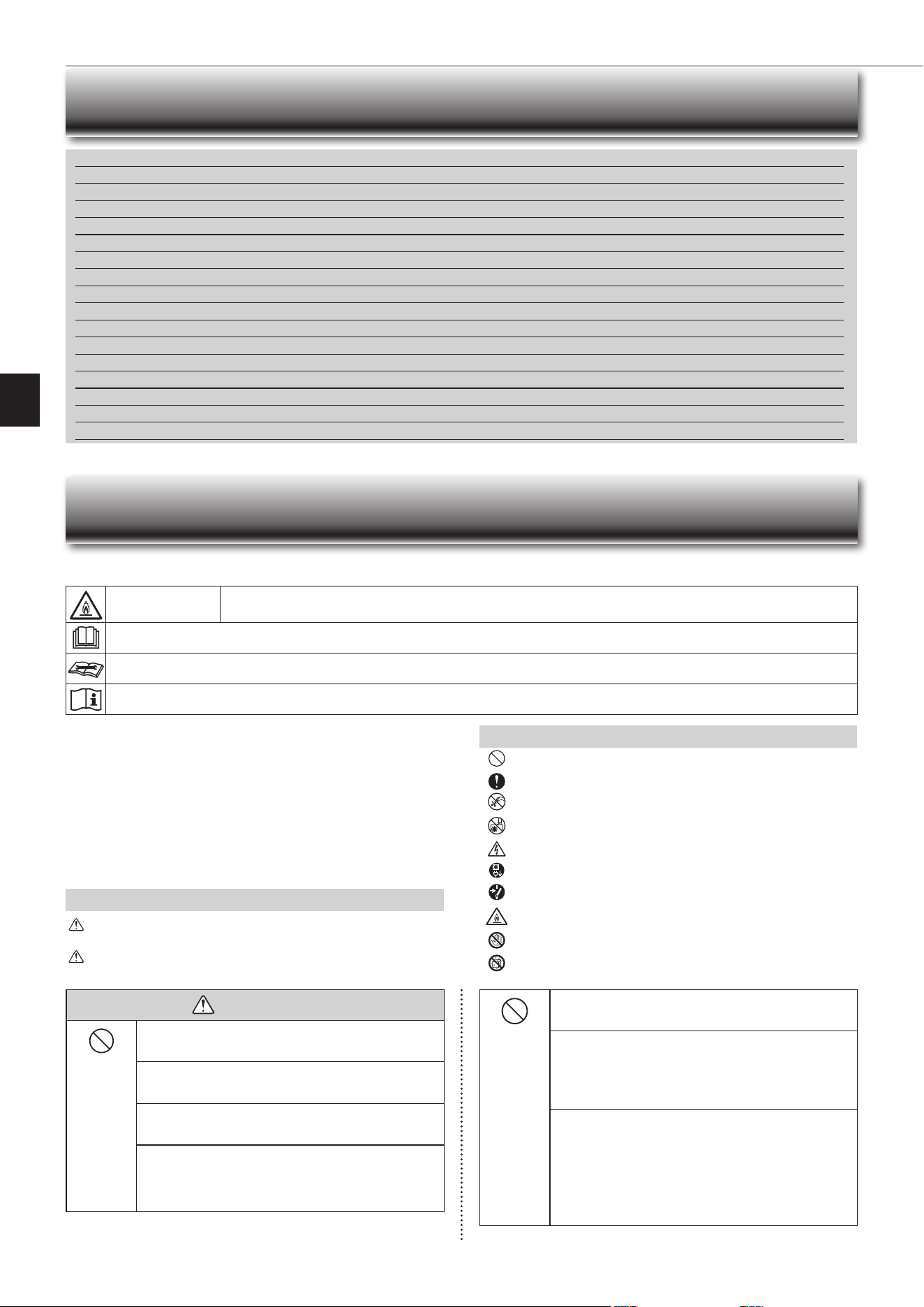
Marks and their meanings
WARNING :
Incorrect handling could cause serious hazard, such as
death,seriousinjury,etc.withahighprobability.
CAUTION:
Incorrect handling could cause serious hazard depending
on the conditions.
Do not expose your body directly to cool air for a prolonged length
of time.
• This could be detrimental to your health.
The unit should not be installed, relocated, disassembled, altered,
or repaired by the user.
• Animproperlyhandledairconditionermaycausere,electricshock,
injury,orwaterleakage,etc.Consultyourdealer.
• Ifthepowersupplycordisdamaged,itmustbereplacedbythemanu-
facturer or its service agent in order to avoid a hazard.
When installing, relocating, or servicing the unit, make sure that
no substance other than the specied refrigerant (R32) enters the
refrigerant circuit.
• Any presence of foreign substance such as air can cause abnormal
pressure rise and may result in explosion or injury.
• Theuseofanyrefrigerantotherthanthatspeciedforthesystemwill
causemechanicalfailure,systemmalfunction,orunitbreakdown.Inthe
worstcase,thiscouldleadtoaseriousimpedimenttosecuringproduct
safety.
Meanings of symbols used in this manual
: Be sure not to do.
: Besuretofollowtheinstruction.
: Neverinsertyourngerorstick,etc.
: Never step onto the indoor/outdoor unit and do not put anything on
them.
: Dangerofelectricshock.Becareful.
: Besuretodisconnectthepowersupplyplugfromthepoweroutlet.
: Besuretoshutoffthepower.
: Riskofre.
: Nevertouchwithwethand.
: Neversplashwaterontheunit.
SAFETY PRECAUTIONS
CONTENTS
Meanings of symbols displayed on indoor unit and/or outdoor unit
WARNING
(Riskofre)
Thisunitusesaammablerefrigerant.
Ifrefrigerantleaksandcomesincontactwithreorheatingpart,itwillcreateharmfulgasandthereisriskofre.
ReadtheOPERATINGINSTRUCTIONScarefullybeforeoperation.
ServicepersonnelarerequiredtocarefullyreadtheOPERATINGINSTRUCTIONSandINSTALLATIONMANUALbeforeoperation.
FurtherinformationisavailableintheOPERATINGINSTRUCTIONS,INSTALLATIONMANUAL,andthelike.
■SAFETYPRECAUTIONS 1
■NAMEOFEACHPART 4
■PREPARATIONBEFOREOPERATION 5
■SELECTINGOPERATIONMODES 6
■FANSPEEDANDAIRFLOWDIRECTIONADJUSTMENT 7
■ I-SAVEOPERATION 8
■ECONOCOOLOPERATION 8
■TIMEROPERATION(ON/OFFTIMER) 8
■ WEEKLYTIMEROPERATION 9
■EMERGENCYOPERATION 10
■AUTORESTARTFUNCTION 10
■CLEANING 11
■
Wi-FiINTERFACESETTINGUP(VGK
TYPEONLY
)
12
■WHENYOUTHINKTHATTROUBLEHASOCCURRED 16
■WHENTHEAIRCONDITIONERISNOTGOINGTOBEUSEDFORALONGTIME 16
■INSTALLATIONPLACEANDELECTRICALWORK 16
■SPECIFICATIONS 17
En-2
This appliance is not intended for use by persons (including children)
with reduced physical, sensory or mental capabilities, or lack of ex-
perience and knowledge, unless they have been given supervision or
instruction concerning use of the appliance by a person responsible
for their safety.
Children should be supervised to ensure that they do not play with
the appliance.
Do not insert your nger, a stick, or other objects into the air inlet
or outlet.
• This may cause injury, since the fan inside rotates at high speeds during
operation.
In case of an abnormal condition (such as a burning smell), stop the
air conditioner and disconnect the power plug or turn the breaker OFF.
• A continued operation in the abnormal state may cause a malfunction,
re,orelectricshock.Inthiscase,consultyourdealer.
When the air conditioner does not cool or heat, there is a possibility of
refrigerant leakage. If any refrigerant leakage is found, stop operations
and ventilate the room well and consult your dealer immediately. If a
repair involves recharging the unit with refrigerant, ask the service
technician for details.
• The refrigerant used in the air conditioner is not harmful. Normally, it
doesnotleak.However,ifrefrigerantleaksandcomesincontactwith
reorheatingpartofsuchafanheater,keroseneheater,orcooking
stove,itwillcreateharmfulgasandthereisriskofre.
The user should never attempt to wash the inside of the indoor unit.
Should the inside of the unit require cleaning, contact your dealer.
• Unsuitable detergent may cause damage to plastic material inside
theunit,whichmayresultinwaterleakage.Shoulddetergentcomein
contactwithelectricalpartsorthemotor,itwillresultinamalfunction,
smoke,orre.
• Theapplianceshallbestoredinaroomwithoutcontinuouslyoperating
ignitionsources(forexample:openames,anoperatinggasappliance
oranoperatingelectricheater).
• Beawarethatrefrigerantsmaynotcontainanodour.
• Do not use means to accelerate the defrosting process or to clean the
appliance, other than those recommended by the manufacturer.
• Do not pierce or burn.
The indoor unit must be installed in rooms which exceed the oor
space specied. Please consult your dealer.
This appliance is intended to be used by expert or trained users in
shops, in light industry and on farms, or for commercial use by lay
persons.
CAUTION
Do not touch the air inlet or the aluminum ns of the indoor/outdoor
unit.
• This may cause injury.
Do not use insecticides, ammable sprays, air refreshers, or antibac-
terial agents on the unit.
• Thismaycauseareordeformationoftheunit.
Do not expose pets or houseplants to direct airow.
• This may cause injury to the pets or plants.
Do not place other electric appliances or furniture under the indoor/
outdoor unit.
• Water may drip down from the unit, which may cause damage or
malfunction.
Do not leave the unit on a damaged installation stand.
• The unit may fall and cause injury.
Do not step on an unstable bench to operate or clean the unit.
• Thismaycauseinjuryifyoufalldown.
Do not pull the power cord.
• Thismaycauseaportionofthecorewiretobreak,whichmaycause
overheatingorre.
Do not charge or disassemble the batteries, and do not throw them
into a re.
•
Thismaycausethebatteriestoleak,orcauseareorexplosion.
Do not operate the unit for more than 4 hours at high humidity (80%
RH or more) and/or with windows or outside door left open.
• Thismaycausethewatercondensationintheairconditioner,which
maydripdown,wettingordamagingthefurniture.
• Thewatercondensationintheairconditionermaycontributetogrowth
of fungi, such as mold.
SAFETY PRECAUTIONS
Do not use the unit for special purposes, such as storing food,
raising animals, growing plants, or preserving precision devices
or art objects.
• This may cause deterioration of quality, or harm to animals and plants.
Do not expose combustion appliances to direct airow.
• This may cause incomplete combustion.
Never put batteries in your mouth for any reason to avoid accidental
ingestion.
• Batteryingestionmaycausechokingand/orpoisoning.
Before cleaning the unit, switch it OFF and disconnect the power plug
or turn the breaker OFF.
• This may cause injury, since the fan inside rotates at high speeds during
operation.
When the unit will be unused for a long time, disconnect the power
plug or turn the breaker OFF.
• Theunitmayaccumulatedirt,whichmaycauseoverheatingorre.
Replace all batteries of the remote controller with new ones of the
same type.
• Usinganoldbatterytogetherwithanewonemaycauseoverheating,
leakage,orexplosion.
If the battery uid comes in contact with your skin or clothes, wash
them thoroughly with clean water.
•
Ifthebatteryuidcomesincontactwithyoureyes,washthemthoroughly
withcleanwaterandimmediatelyseekmedicalattention.
Ensure that the area is well-ventilated when the unit is operated
together with a combustion appliance.
• Inadequate ventilation may cause oxygen starvation.
Do not operate the air conditioner after applying protecting agent
on the oor.
• Components in the protecting agent may attach the inside of the indoor
unit,resultinginwaterleakageorsplatteringofdew.
Turn the breaker OFF when you hear thunder and there is a possibility
of a lightning strike.
• Theunitmaybedamagediflightningstrikes.
After the air conditioner is used for several seasons, perform inspec-
tion and maintenance in addition to normal cleaning.
• Dirt or dust in the unit may create an unpleasant odor, contribute to
growthoffungi,suchasmold,orclogthedrainpassage,andcause
watertoleakfromtheindoorunit.Consultyourdealerforinspection
andmaintenance,whichrequirespecializedknowledgeandskills.
Do not operate switches with wet hands.
• Thismaycauseelectricshock.
Do not clean the air conditioner with water or place an object that
contains water, such as a ower vase, on it.
• Thismaycausereorelectricshock.
Do not step on or place any object on the outdoor unit.
• Thismaycauseinjuryifyouortheobjectfallsdown.
IMPORTANT
Dirty lters cause condensation in the air conditioner which will contribute to the
growth of fungi such as mold. It is therefore recommended to clean air lters every
2 weeks.
Before starting the operation, ensure that the horizontal vanes are in the closed posi-
tion. If operation starts when the horizontal vanes are in the open position, they may
not return to the correct position.
En-3
● OPERATING INSTRUCTIONS ●
For Wi-Fi interface
WARNING
Consult your dealer for installing the air conditioner.
• It should not be installed by the user since installation requires specialized
knowledgeandskills.Animproperlyinstalledairconditionermaycause
waterleakage,re,orelectricshock.
Provide a dedicated power supply for the air conditioner.
• Anon-dedicatedpowersupplymaycauseoverheatingorre.
Do not install the unit where ammable gas could leak.
• Ifgasleaksandaccumulatesaroundtheoutdoorunit,itmaycausean
explosion.
Earth the unit correctly.
• Donotconnecttheearthwiretoagaspipe,waterpipe,lightningrod,or
atelephoneearthwire.Improperearthingmaycauseelectricshock.
CAUTION
Install an earth leakage breaker depending on the installation location
of the air conditioner (such as highly humid areas).
• Ifanearthleakagebreakerisnotinstalled,itmaycauseelectricshock.
Ensure that the drain water is properly drained.
• Ifthedrainpassageisimproper,watermaydripdownfromtheindoor/
outdoorunit,wettinganddamagingthefurniture.
In case of an abnormal condition
Immediately stop operating the air conditioner and consult your dealer.
For installation
SAFETY PRECAUTIONS
WARNING
(Improper handling may have serious consequences, including serious
injuryordeath.)
This appliance can be used by children aged from 8 years and above
and persons with reduced physical, sensory or mental capabilities or
lack of experience and knowledge if they have been given supervi-
sion or instruction concerning use of the appliance in a safe way and
understand the hazards involved.
Children shall not play with the appliance. Cleaning and user mainte-
nance shall not be made by children without supervision.
Do not use the Wi-Fi interface nearby the medical electrical equipment
or people who have a medical device such as a cardiac pacemaker
or an implantable cardioverter-debrillator.
• It can cause an accident due to malfunctions of the medical equipment
or device.
Do not install the Wi-Fi interface nearby the automatic control devices
such as automatic doors or re alarms.
• It can cause accidents due to malfunctions.
Do not touch the Wi-Fi interface with wet hands.
• Itcancausedamagetothedevice,electricshock,orre.
Do not splash water on the Wi-Fi interface or use it in a bathroom.
• Itcancausedamagetothedevice,electricshock,orre.
When the Wi-Fi interface is dropped, or the holder or cable is dam-
aged, disconnect the power supply plug or turn the breaker OFF.
• Itmaycausereorelectricshock.Inthiscase,consultyourdealer.
•
This device complies withall Australia and New zealand
regulrementsforEMCandelectricalsafety.
CAUTION
(Improper handling may have consequences, including injury or damage
tobuilding.)
Do not step on unstable stepstool to set up or clean the Wi-Fi interface.
• Itmaycauseinjuryifyoufalldown.
Do not use the Wi-Fi interface nearby other wireless devices, micro-
waves, cordless phones, or facsimiles.
• It can cause malfunctions.
En-4
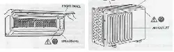
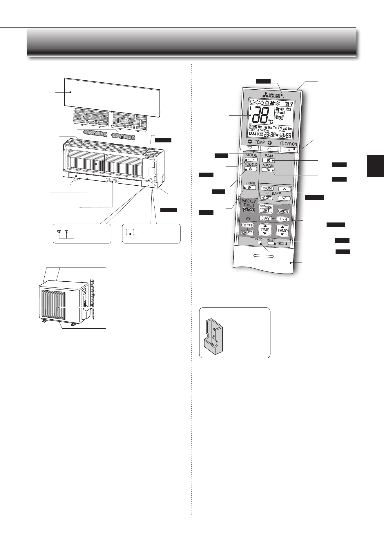
NAME OF EACH PART
Remote controller holder
• Install the remote
controller holder in a
placewherethesignal
can be received by the
indoor unit.
• When the remote
controller is not used,
place it in this holder.
Operation
indicator lamp
Remote control
receiving section
Emergency
operation
switch
Page10
Horizontalvane
Air inlet
Airlter
(Nanoplatinumlter)
Aircleaninglter
(
Electrostaticanti-allergy
enzymelter,option
)
Heatexchanger
Front panel
Outdoor unit
Indoor unit Remote controller
Airinlet(backandside)
Refrigerant piping
Drainage hose
Air outlet
Drain outlet
Outdoorunitsmaybedifferentinappearance.
Signal transmitting
section
Distance of signal :
About6m
Beep(s)is(are)heard
from the indoor unit
whenthesignalis
received.
Operation
display section
OFF/ON
(stop/operate)button
Temperature
buttons
Page6
Operation
select button
Page6
ECONOCOOL
button Page 8
FAN speed control
button Page7
VANEcontrol
button Page7
TIME,TIMERsetbuttons
Page5,8
forwardbutton
backwardbutton
CLOCKbuttonPage5
RESETbuttonPage5
Lid
Slidetheliddowntoopen
the remote controller. Slide
itdownfurthertogettothe
weeklytimerbuttons.
i-save button
Page 8
TIMER,WEEKLYTIMER
set buttons
Page5,9
Air outlet
Battery replacement indicator
Page5
Onlyusetheremotecontrollerprovided
withtheunit.
Do not use other remote controllers.
If2ormoreindoorunitsareinstalledin
proximity to one another, an indoor unit
that is not intended to be operated may
respond to the remote controller.
Wi-Fi interface
Page12
Fan guard
En-5
● OPERATING INSTRUCTIONS ●
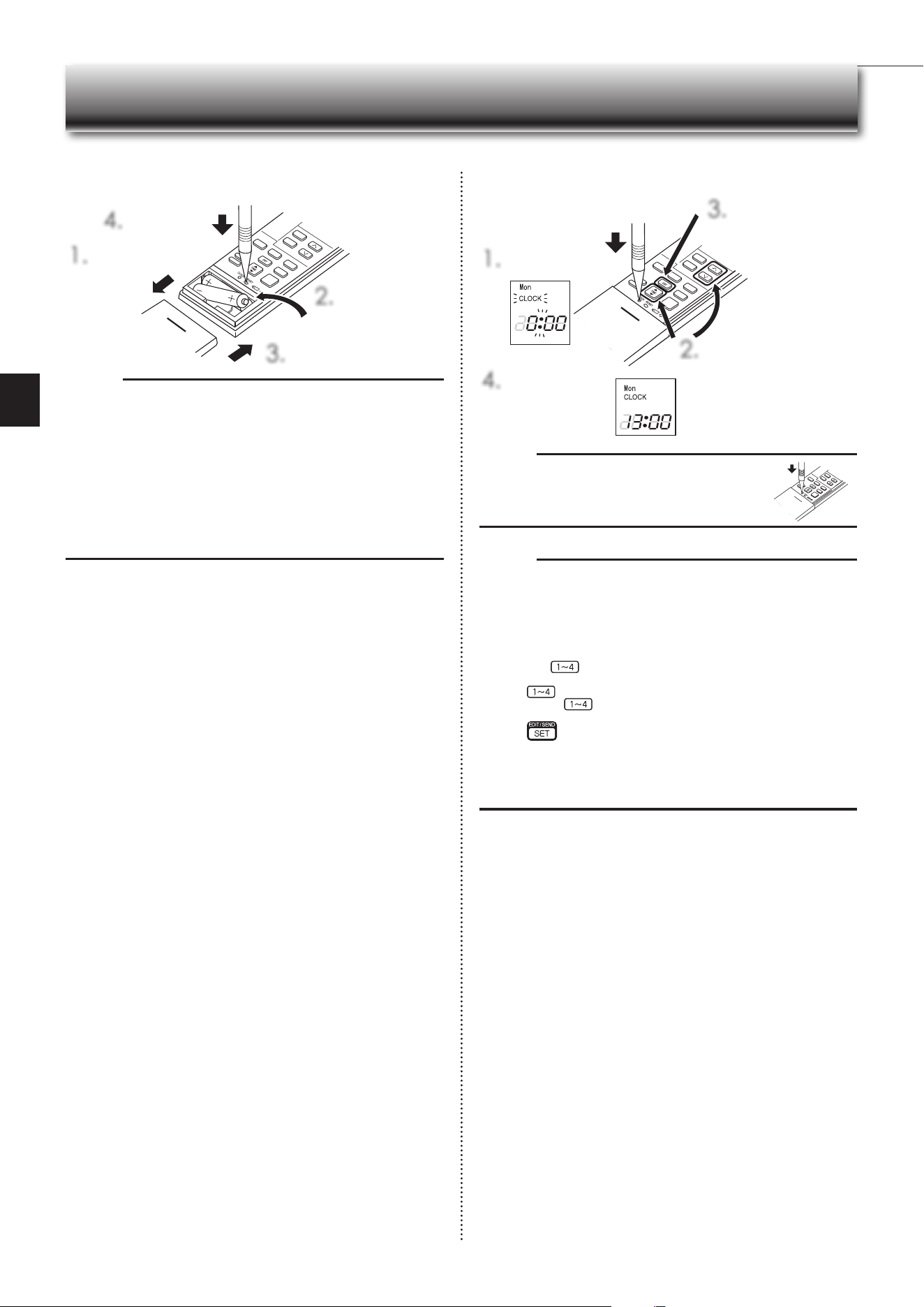
PREPARATION BEFORE OPERATION
Note:
• PressCLOCKgentlyusingathininstrument.
Before operation:Insertthepowersupplyplugintothepoweroutletand/orturnthebreakeron.
Installing the remote controller batteries Setting current time
1.
Remove the front lid.
3.
Install the front lid.
4.
PressRESET.
1.
PressCLOCK.
4.
PressCLOCKagain.
2.
PresseithertheTIMEbuttonor
theTIMERbuttonstosetthe
time.
Eachpresschangestheclock
1minuteforward/backward(10
minuteswhenpressedlonger).
3.
PresstheDAYbutton
to set the day.
2.
Insert the negative
pole of AAA
alkalinebatteriesrst.
Note:
• Makesurethepolarityofthebatteriesiscorrect.
• Donotusemanganesebatteriesandleakingbatteries.Theremotecontroller
could malfunction.
• Do not use rechargeable batteries.
• Thebatteryreplacementindicatorlightsupwhenthebatteryisrunninglow.
Inabout7daysaftertheindicatorstartslightsup,theremotecontrollerstops
working.
• Replaceallbatterieswithnewonesofthesametype.
• Batteries canbeused forapproximately1 year.However,batterieswith expired
shelf lives last shorter.
• PressRESETgentlyusingathininstrument.
IftheRESETbuttonisnotpressed,theremotecontrollermaynotoperate
correctly.
Note:
How to set remote controller exclusively for a particular indoor unit
Amaximumof4indoorunitswithwirelessremotecontrollerscan beusedin
a room.
Tooperate the indoorunits individually witheach remote controller,assign a
number to each remote controller according to the number of the indoor unit.
Thissettingcanbesetonlywhenallthefollowingconditionsaremet:
• TheremotecontrollerispoweredOFF.
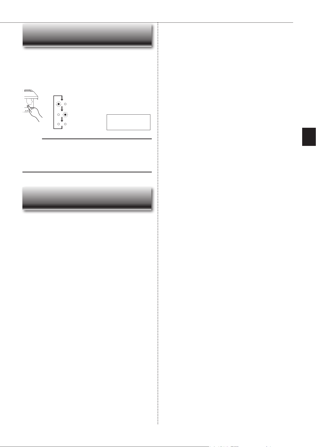
(1)Holddown
buttonontheremotecontrollerfor2secondstoenterthe
pairing mode.
(2)Press
button again and assign a number to each remote controller.
Eachpressof
buttonadvancesthenumberinthefollowingorder:1→
2→3→4.
(3)Press
button to complete the pairing setting.
AfteryouturnthebreakerON,theremotecontrollerthatrstsendsasignal
toanindoorunitwillberegardedastheremotecontrollerfortheindoorunit.
Once they are set, the indoor unit will only receive the signal from the
assigned remote controller afterwards.The setting of indoor unit will be
canceled,ifthebreakeristernedOFForthepowersupplyisshutdown.
En-6
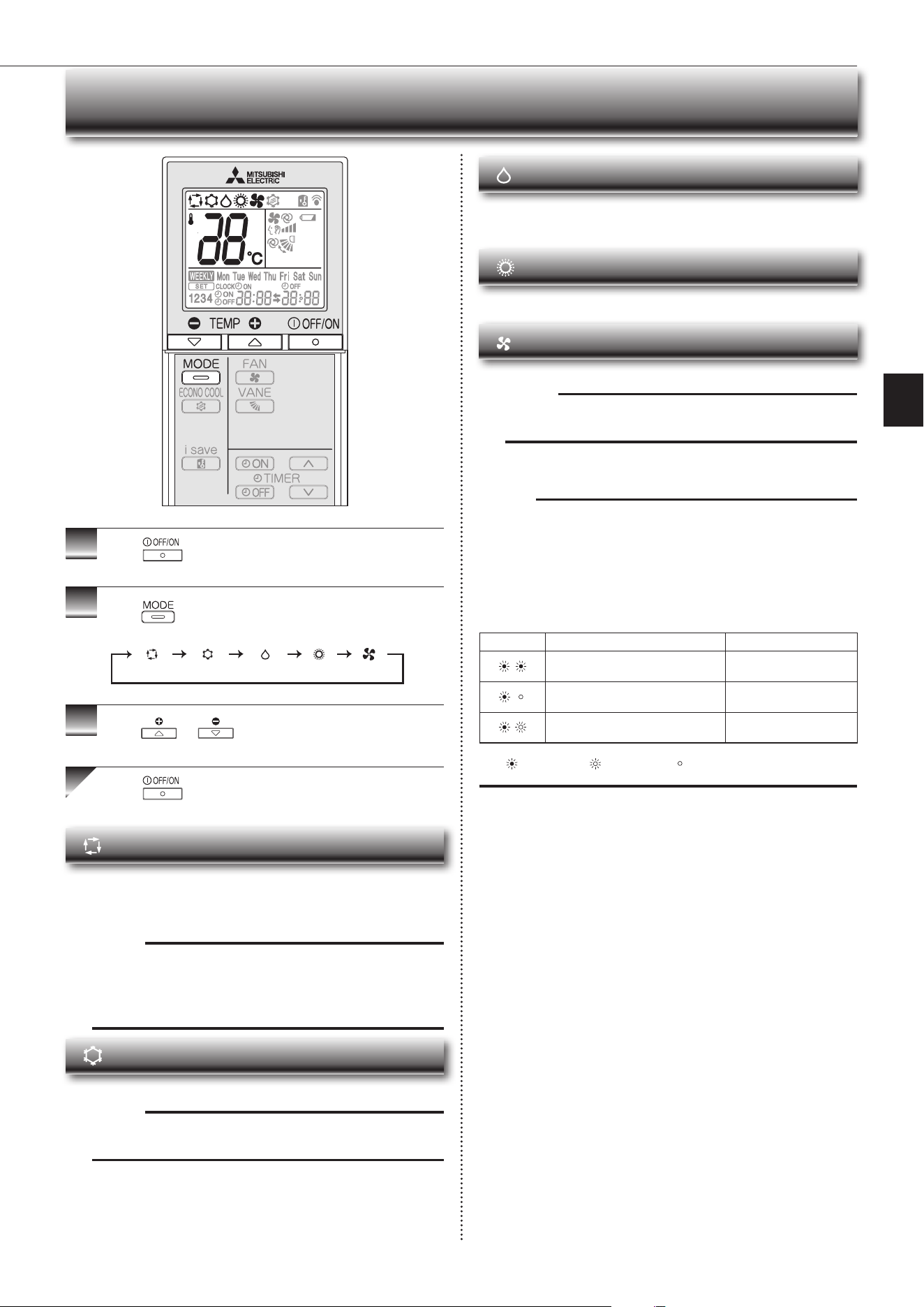
SELECTING OPERATION MODES
1
Press
to start the operation.
2
Press toselectoperationmode.Eachpress
changesmodeinthefollowingorder:
3
Press or to set the temperature.
Eachpressraisesorlowersthetemperatureby1°C.
Press to stop the operation.
(AUTO) (COOL) (DRY) (HEAT) (FAN)
Note:
Multi syst em operation
Twoormoreindoorunitscanbeoperatedbyoneoutdoorunit.Whenseveralin-
door units are operated simultaneously, cooling/fan and heating operations can-
notbedoneatthesametime.WhenCOOL/FANisselectedwithoneunitand
HEATwithanotherorviceversa,theunitselectedlastgoesintostandbymode.
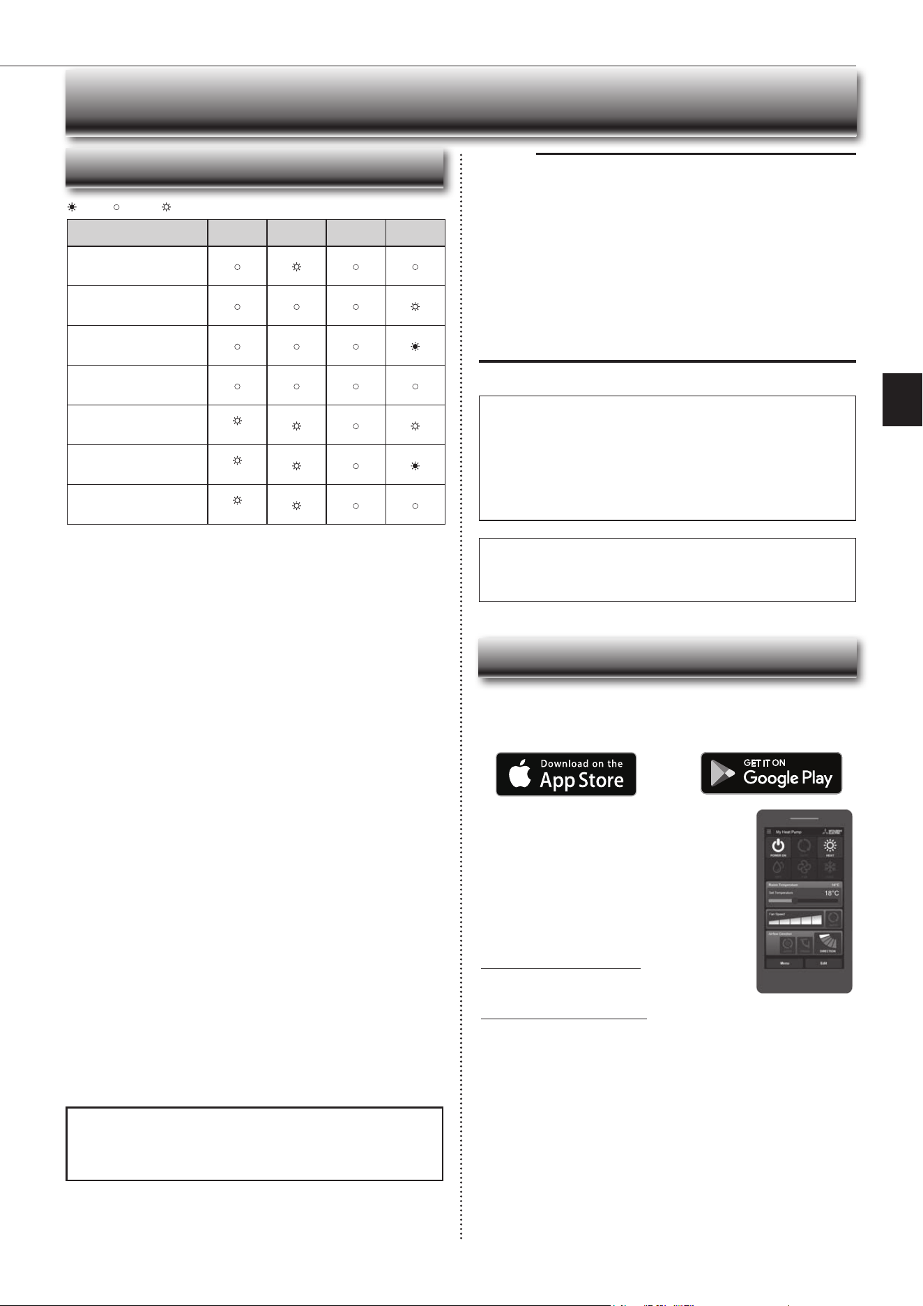
Operation indic a t or lamp
Theoperationindicatorlampshowstheoperationstateoftheunit.
Indication Operationstate Room temperature
The unit is operating to reach the set
temperature
About2°Cormoreaway
from set temperature
The room temperature is approach-
ing the set temperature
About 1 to 2°C from set
temperature
Standby mode (only during multi
systemoperation)
—
Lit Blinking Not lit
AUTO mode (Auto change over)
Theunitselectstheoperationmodeaccordingtothedifferencebetweenthe
roomtemperature and thesettemperature. DuringAUTOmode, theunit
changesmode(COOL↔HEAT)whentheroomtemperatureisabout2°C
awayfromthesettemperatureformorethan15minutes.
Note:
AutoModeisnotrecommendedifthisindoorunitisconnectedtoaMXZ
type outdoor unit. When several indoor units are operated simultaneously,
theunit maynotbe ableto switchoperationmode betweenCOOL and
HEAT.Inthiscase,theindoorunitbecomesstandbymode(Refertotable
ofOperationindicatorlam
p)
.
COOL mode
Enjoycoolairatyourdesiredtemperature.
Note:
Do not operate COOL mode at very low outside temperatures (less than
-10°C).Watercondensedintheunitmaydripandwetordamagefurniture,etc.
DRY mode
Dehumidify your room. The room may be cooled slightly.
TemperaturecannotbesetduringDRYmode.
HEAT mode
Enjoywarmairatyourdesiredtemperature.
FAN mode
Circulate the air in your room.
Note:
After COOL/DRY mode operation, it is recommended to operate in the
FAN mode to dry inside the indoor unit.
En-7
● OPERATING INSTRUCTIONS ●
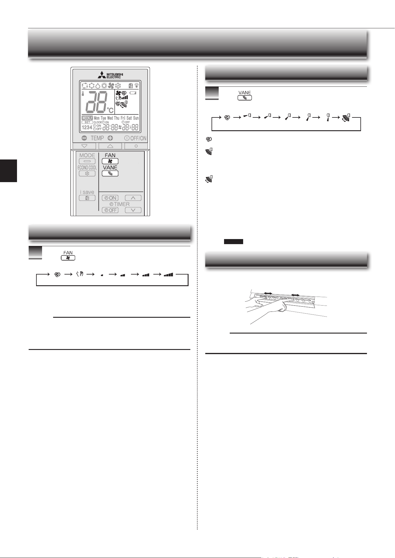
FAN SPEED AND AIRFLOW DIRECTION ADJUSTMENT
1
Press toselectfanspeed.Eachpresschanges
fanspeedinthefollowingorder:
• TwoshortbeepsareheardfromtheindoorunitwhensettoAUTO.
• Usehigherfanspeedtocool/heattheroomquicker.Itisrecommend-
edtolowerthefanspeedoncetheroomiscool/warm.
• Uselowerfanspeedforquietoperation.
Note:
Multi syst em operation
When several indoor units are operated simultaneously by one outdoor unit for
heatingoperation,thetemperatureoftheairowmaybelow.Inthiscase,itis
recommendedtosetthefanspeedtoAUTO.
(AUTO) (Quiet) (Low) (Medium) (High) (SuperHigh)
Left-right Airflow direction
■ To change the horizontal airow direction.
Movetheverticalvanemanuallybeforestartingoperation.
Fan speed
Up-down Airflow direction
1
Press toselectairowdirection.Eachpress
changesairowdirectioninthefollowingorder:
(AUTO) .........Thevaneissettothemostefcientairowdirection.COOL/
DRY/FAN:horizontalposition.HEAT:position(4).
(Manual) .......For efficient air conditioning, select the upper position for
COOL/DRY, and the lower position for HEAT. If the lower
positionisselectedduringCOOL/DRY,thevaneautomatically
movestotheupwardpositionafter0.5to1hourtoprevent
any condensation from dripping.
(Swing) .........Thevanemovesupanddownintermittently.
• TwoshortbeepsareheardfromtheindoorunitwhensettoAUTO.
• Alwaysusetheremotecontrollerwhenchangingthedirectionofair-
flow.Movingthehorizontalvaneswithyourhandscausesthemtomal-
function.
• Whenthebreakeristurnedon,thehorizontalvanes’positionwillbe
resetinaboutaminute,thentheoperationwillstart.Thesameistrue
in the emergency cooling operation.
• When the horizontal vanes seem to be in an abnormal position, see
page11 .
(AUTO) (1) (2) (3) (4) (5) (SWING)
Note:
If the vertical vanes are adjusted, be sure to return the horizontal vanes to the
original closed position.
En-8
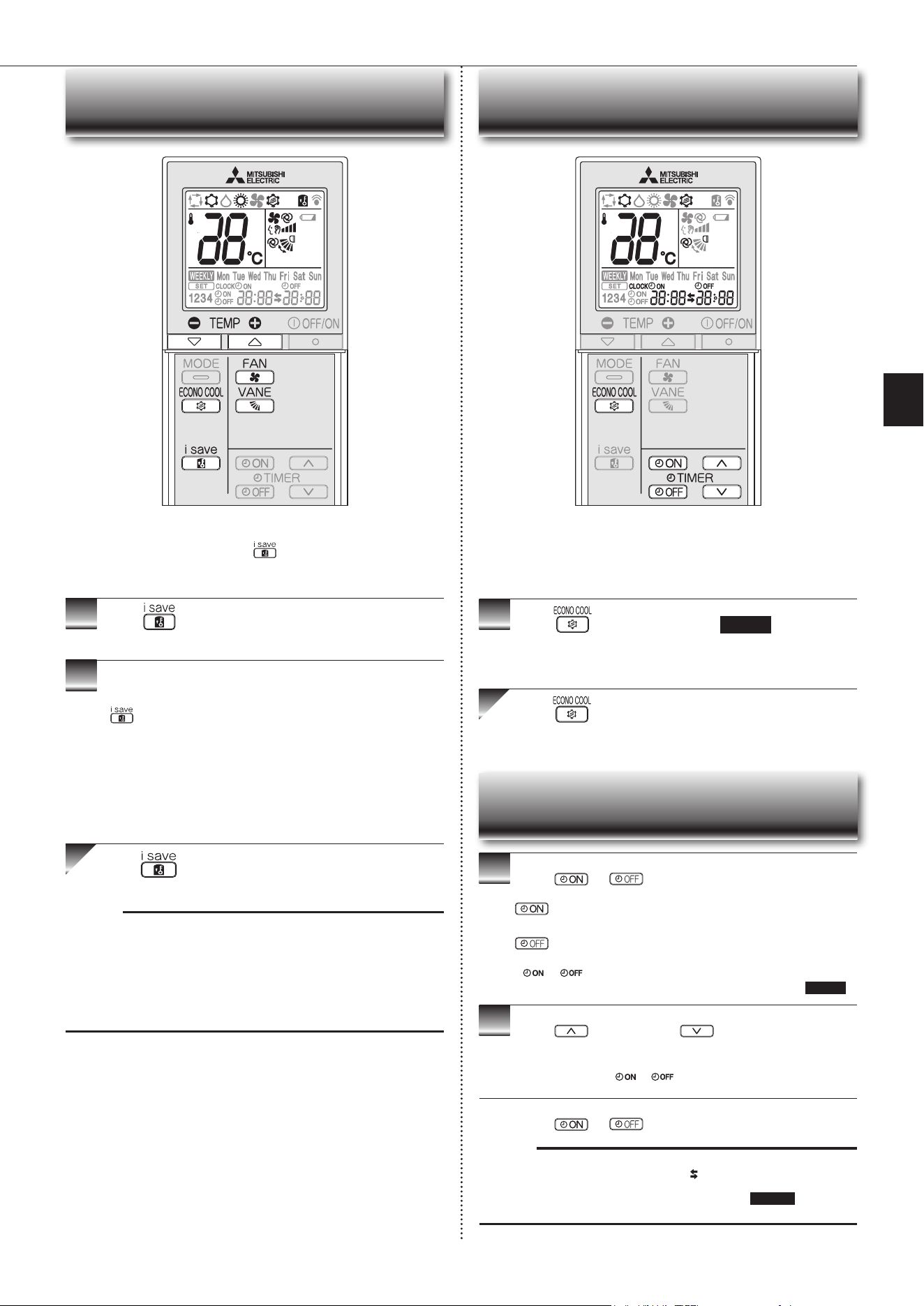
I-SAVE OPERATION ECONO COOL OPERATION
• Asimpliedsetbackfunctionenablestorecallthepreferred(preset)
settingwithasinglepushofthe button. Press the button again
andyoucangobacktotheprevioussettinginaninstance.
• i-saveoperationcannotbesetontheweeklytimer.
1
Press duringCOOL,ECONOCOOL,orHEAT
mode to select i-save mode.
2
Setthetemperature,fanspeed,andairowdirection.
• The same setting is selected from the next time by simply pressing
.
• Twosettingscanbesaved.(One forCOOL/ECONO COOL,onefor
HEAT)
• Select the appropriate temperature, fan speed,andairflowdirection
according to your room.
• Normally, the minimum temperature setting in HEATmode is 16°C.
However,duringi-saveoperationonly,theminimumtemperatureset-
tingis10°C.
Press again to cancel i-save operation.
• i-saveoperationalsoiscancelledwhentheMODEbuttonispressed.
Note:
Exampleofuse:
1.Lowenergymode
Setthetemperature2°Cto3°CwarmerinCOOLandcoolerinHEATmode.
Thissettingissuitableforunoccupiedroom,andwhileyouaresleeping.
2.Savingfrequentlyusedsettings
SaveyourpreferredsettingforCOOL/ECONOCOOLandHEAT.Thisena-
blesyoutoselectyourpreferredsettingwithasinglepushofthebutton.
Swingairow(changeofairow)makesyoufeelcoolerthanstationary
airow.Thesettemperatureandtheairowdirectionareautomatically
changed by the microprocessor. It is possible to perform cooling opera-
tionwithkeepingcomfort.Asaresultenergycanbesaved.
1
Press duringCOOLmodepage6 to start
ECONOCOOLoperation.
Theunitperformsswingoperationverticallyinvariouscyclesaccordingtothe
temperatureairflow.
Press againtocancelECONOCOOLoperation.
• ECONOCOOLoperationisalsocancelledwhentheVANEbuttonis
pressed.
1
Press or during operation to set the timer.
(ONtimer): TheunitturnsONatthesettime.
(OFFtimer): TheunitturnsOFFatthesettime.
*
or blinks.
*
Make sure that the current time and day are set correctly.
Page5
2
Press (forward)and (backward)tosetthe
time of timer.
Eachpresschangesthesettime10minutesforward/backward.
• Setthetimerwhile
or isblinking.
Press
or
again to cancel timer.
Note:
• ONandOFFtimerscanbesettogether.
markindicatestheorderoftimer
operations.
• IfpowerfailureoccurswhileON/OFFtimerisset,see
page10 “Auto restart
function”.
TIMER OPERATION (ON/OFF TIMER)
En-9
● OPERATING INSTRUCTIONS ●
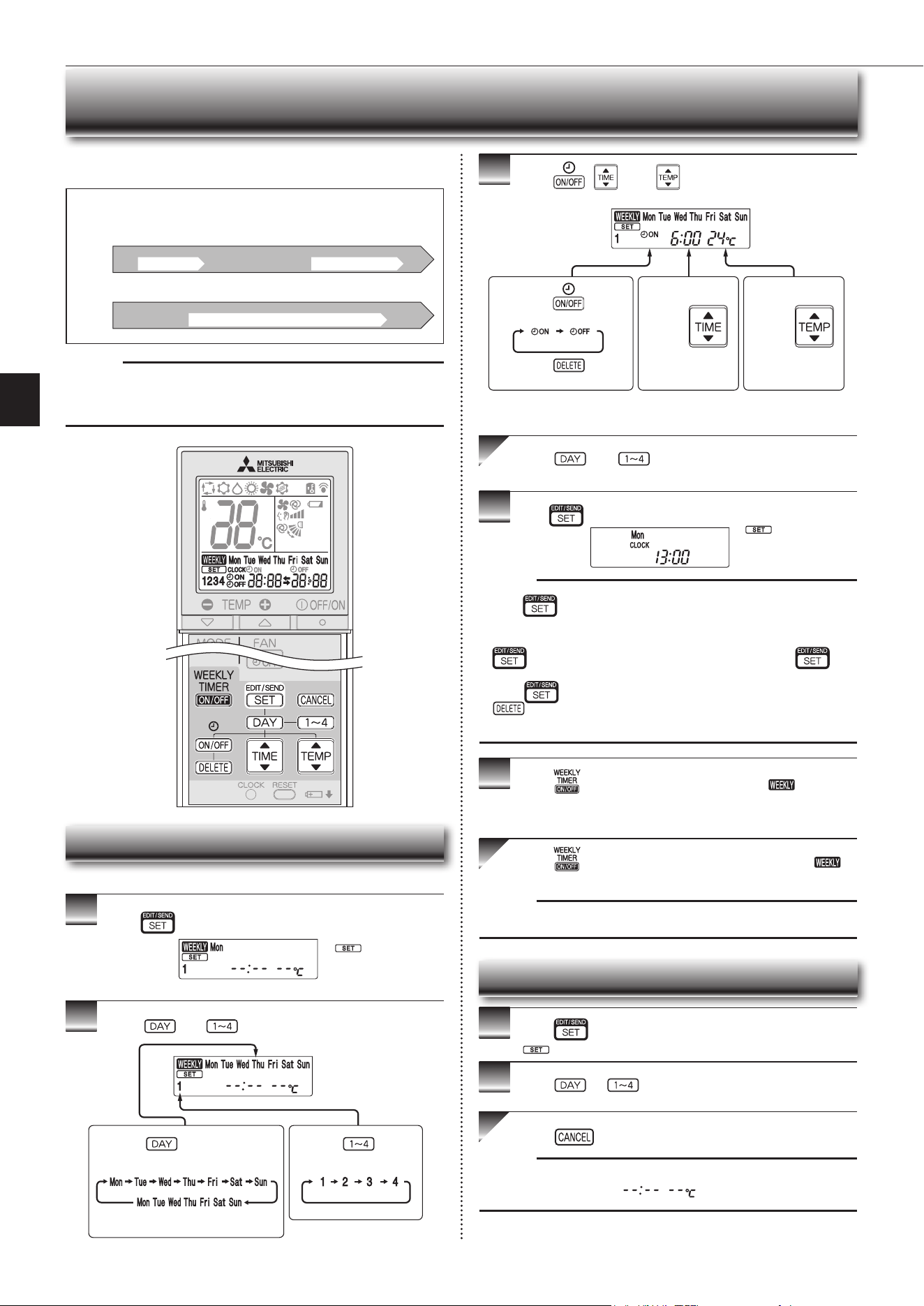
WEEKLY TIMER OPERATION
• Amaximumof4ONorOFFtimerscanbesetforindividualdaysoftheweek.
• Amaximumof28ONorOFFtimerscanbesetforaweek.
Setting the weekly timer
* Makesurethatthecurrenttimeanddayaresetcorrectly.
1
Press toentertheweeklytimersettingmode.
2
Press and to select setting day and number.
3
Press , , and tosetON/OFF,time,and
temperature.
Press and to continue setting the timer for
other days and/or numbers.
4
Press tocompleteandtransmittheweeklytimersetting.
Note:
• Press
totransmitthesettinginformationofweeklytimertotheindoor
unit.Pointtheremotecontrollertowardtheindoorunitfor3seconds.
• Whensettingthetimerformorethanonedayoftheweekoronenumber,
does not have to be pressed per each setting. Press once
afterallthesettingsarecomplete.Alltheweeklytimersettingswillbesaved.
• Press
toenterthe weekly timer setting mode, and press andhold
for 5 seconds to erase all weekly timer settings. Point the remote
controllertowardtheindoorunit.
5
Press toturntheweeklytimerON.( lights.)
* WhentheweeklytimerisON,thedayoftheweekwhosetimersetting
iscomplete,willlight.
Press againtoturntheweeklytimerOFF.(
goesout.)
Note:
ThesavedsettingswillnotbeclearedwhentheweeklytimeristurnedOFF.
Checking weekly timer setting
1
Press toentertheweeklytimersettingmode.
* blinks.
2
Press or toviewthesettingoftheparticular
day or number.
Press toexittheweeklytimersetting.
Note:
Whenalldaysoftheweekareselectedtoviewthesettingsandadifferent set-
ting is included among them,
willbedisplayed.
*
whichwasblink-
ing goes out, and the
currenttimewillbe
displayed.
* blinks.
Note:
ThesimpleON/OFFtimersettingisavailablewhiletheweeklytimerison.In
thiscase,theON/OFFtimerhaspriorityovertheweeklytimer;theweeklytimer
operationwillstartagainafterthesimpleON/OFFtimeriscomplete.
E.g. : Runs at 24°C from waking up to leaving home, and runs at 27°C from
getting home to going to bed on weekdays.
Runs at 27°C from waking up late to going bed early on weekends.
Setting1 Setting2 Setting3 Setting4
Setting1 Setting2
6:00 8:30 17:30 22:00
24°C 27°C
ON OFF ON OFF
ON OFF
Mon
Fri
~
Sat
Sun
~
27°C
Pressing selects the day of
theweektobeset.
Pressing selects
the setting number.
* All days can be selected.
E.g.: [MonTue...Sun]
and[1]areselected.
E.g.: [ON],[6:00]
and[24°C]are
selected.
Pressing
selectsON/OFFtimer.
Pressing
deletes timer setting.
Pressing
adjusts the time.
Pressing
adjusts the tem-
perature.
* Holddownthebuttontochangethetimequickly.
* Thetemperaturecanbesetbetween16°Cand31°Catweeklytimer.
8:00 21:00
En-10
Operation indicator lamp
Settemperature:24°C
Fanspeed:Medium
Horizontalvane:Auto
EmergencyCOOL
EmergencyHEAT
Stop
When the remote controller cannot be used...
Emergencyoperationcanbe activated by pressing the emergencyoperation
switch(E.O.SW)ontheindoorunit.
EachtimetheE.O.SWispressed,theoperationchangesin
thefollowingorder:
Ifapowerfailureoccursorthemainpoweristurnedoffduringoperation,“Auto
restart function” automatically starts operation in the same mode as the one set
withtheremotecontrollerjustbeforetheshutoffofthemainpower.Whentimeris
set,timersettingiscancelledandtheunitstartsoperationwhenpowerisresumed.
If you do not want to use this function, please consult the service repre-
sentative because the setting of the unit needs to be changed.
Note:
• Therst30minutesofoperationistestrun.Temperaturecontroldoesnot
work,andfanspeedissettoHigh.
• Intheemergencyheatingoperation,thefanspeedgraduallyrisestoblowout
warmair.
• In the emergency cooling operation, the horizontal vanes’ position will be
resetinaboutaminute,thentheoperationwillstart.
EMERGENCY OPERATION
AUTO RESTART FUNCTION
En-11
● OPERATING INSTRUCTIONS ●
Inst ruc t ions:
CLEANING
• Switchoffthepowersupplyorturnoffthebreakerbeforecleaning.
• Becarefulnottotouchthemetalpartswithyourhands.
• Donotusebenzine,thinner,polishingpowder,orinsecticide.
• Whendirtstandsout,washitwithkitchenneutraldetergentdilutedwith
lukewarmwatertothespeciedconcentration,thenwipeoffthedetergent
withadamptowel.
• Donotuseascrubbingbrush,ahardsponge,orthelike.
• Donotsoakorrinsethehorizontalvane.
• Donotusewaterhotterthan50°C.
• Donotexposepartstodirectsunlight,heat,orretodry.
• Donotapplyexcessiveforceonthefanasitmaycausecracksorbreakage.
Im porta nt
• Clean the lters regularly for best performance and to
reduce pow e r consumption.
• Dirty lters cause condensation in the air conditioner
which will contribute to the growth of fungi such as
mold. It is therefore recommended to clean air lters
every 2 w eek s.
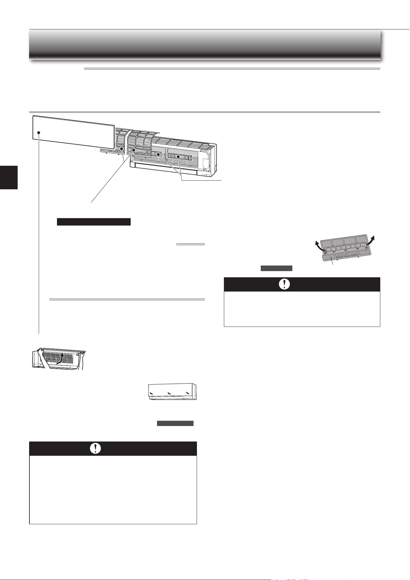
Front panel
1.Liftthefrontpaneluntila“click”isheard.
2.Close the front panel securely and press the
positionsindicatedbythearrows.
3.Cleanthefrontpanelwithoutdetachingitfromthe
unit.
• Wipewithasoftdrycloth.Adedicatedsoftdryclothisonlyprovidedwith
MSZ-EF**VGBtype.
• UsethededicatedSOFTDRYCLOTH.PartsNumber
MAC-1001CL-E
• Donotsoakthefrontpanelinwater.
Im porta nt
• The surface of the indoor unit is easily scratched, so never
rub or hit the unit with something hard. Also, when installing
or removing the front panel, handle it with care to prevent
scra tche s on it.
• Do not use abrasive cleaner to prevent scratches on the sur-
face of the indoor unit.
• It is very easy to get ngerprints on the surface of the indoor
unit. When ngerprints are noticeable, gently wipe them off
with a soft dry cloth.
• When using a commercially available chemical impregnated
cloth, follow its instructions.
• Do not leave the front panel open for a prolonged time.
Air cleaning lter
(Electrostatic anti-allergy enzyme
lter, option)
Every 3 months:
• Remove dirt by a vacuum cleaner.
When dirt cannot be removed by vacuum cleaning:
•
Soakthelteranditsframeinlukewarmwaterbeforerinsingit.
•
After washing, dry it well in shade.
Installalltabsoftheairlter.
Every ye a r:
• Replace itwitha newaircleaning
lterforbestperformance.
• Parts Number
MAC-2320FT
Pulltoremovefromtheairlter
Air lter (Nano platinum lter)
•
Clea n eve ry 2 w e ek s
• Removedirtbyavacuumcleaner,orrinsewithwater.
• Afterwashingwithwater,dryitwellinshade.
What is “Nano platinum lter” ?
Nano platinum is a ceramic particle that includes a platinum nanoparti-
cle. The particles are incorporated into the lter material, which results
in providing semi-permanent antibacterial and deodorizing characteris-
tics for the lter. Nano platinum surpasses the catechin (a bioavonoid
thatisfoundingreentea)inperformance.Nanoplatinumlterusesthis
compound not only to improve air quality but also to eliminate bacteria
andviruses.Thisairlterhasasemi-permanentlastingeffectevenafter
washingitwithwater.
En-12
Wi-Fi INTERFACE SETTING UP (VGK TYPE ONLY)
This Wi-Fi interface, communicates the status information and controls
the commands from the server by connecting to the indoor unit.
Wi-Fi interface
Wi-Fi interface
Front panel
Front panel
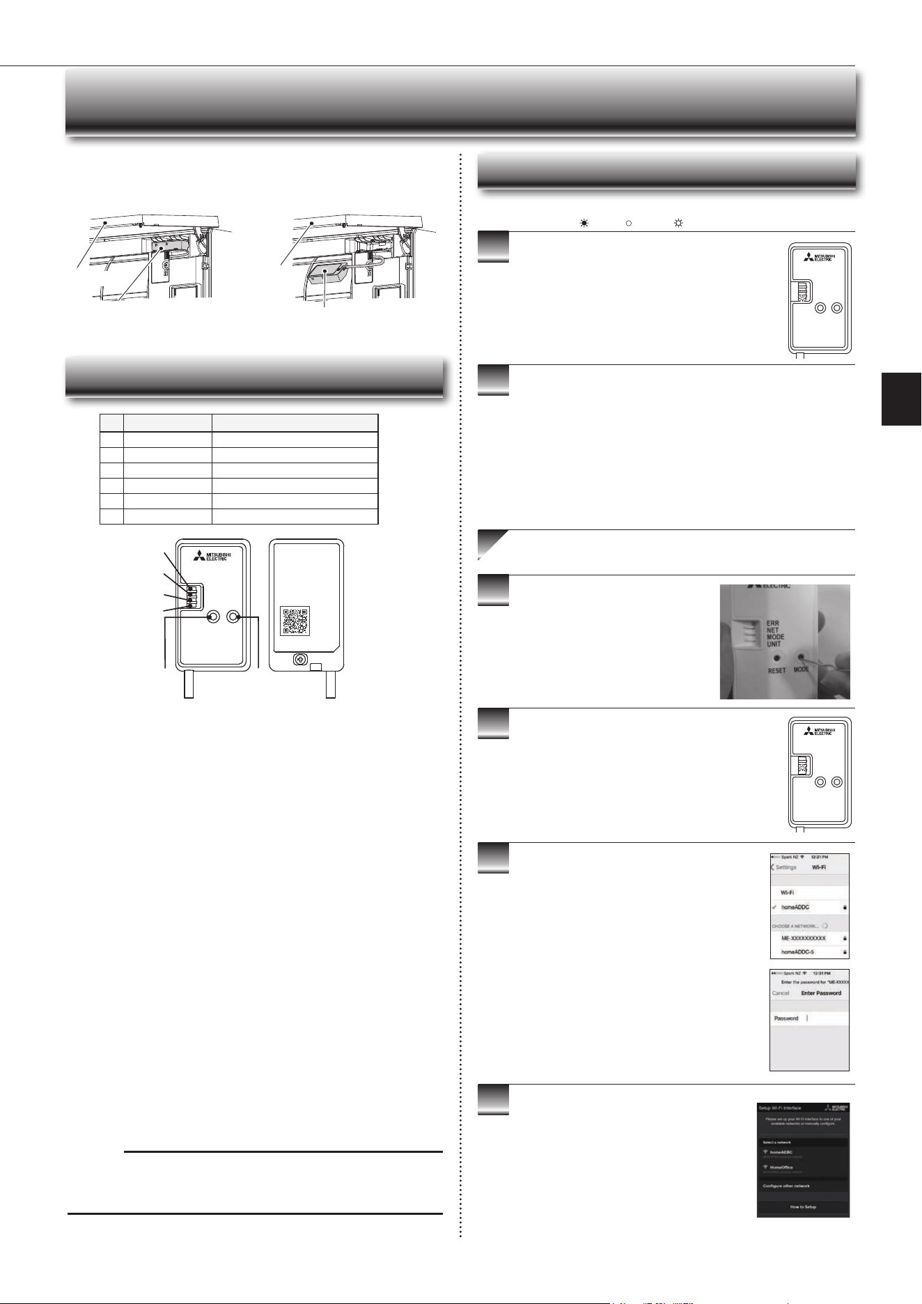
Wi-Fi interface introduction
ERR
NET
MODE
UNIT
RESET
MODE
Wi-Fi
INTERFACE
MODEL
XXXXXXXX
MAC
ID
SSID
KEY
: XXXXXXXXXXXX
: XXXXXXXXXX
: XXXXXXXXXXXX
: XXXXXXXXXXXX
VOLTAGE
CURRENT
:
:
MITSUBISHI ELECTRIC CORPORATION
WiFi.ASSY DWG No.
XXXXXXXXXXX
MADE IN CHINA
XXXXXXXXXX
>PP<
3
4
5
6
2
1
Note:
WhentheWi-Fiinterfaceisresettothefactorydefault,ALLthe
congurationinformationwillbelost.Takegreatcareinimplementingthis
operation.
(2) RESET Button
• HolddowntheRESETButtonfor2secondstorebootthesystem.
• HolddowntheRESETButtonfor14secondstoinitialisetheWi-Fiinterface
to the factory default.
No Item Description
1
MODEButton Selects modes.
2
RESETButton ResetsthesystemandALLsettings.
3
ERRLED(Orange) Showsthenetworkerrorstate.
4
NETLED(Green) Showsthenetworkstate.
5
MODELED(Orange) ShowstheAccessPointModestate.
6
UNITLED(Green) Showstheindoorunitstate.
3
4
5
6
Information for users
ThefollowingstepsexplainhowtoconnecttheWi-FiinterfacetoaRouter.
1
2
THERE ARE TWO OPTIONS OF
CONNECTING
EnsuretheWi-Fiinterfaceisconnectedcorrectlyasper
theprevioussection,‘ConnectingtheWi-Fiinterface’.
UNITLEDshouldbeashinggreenonly.
: ON : Flashing : OFF
KEY (LED LIGHTS):
DownloadandinstallWi-FiControlApptoyour
compatible Apple or Android smartphone/tablet
(searchterm:MitsubishiWi-FiControl).
ActivateAccessPointModeonyour
Wi-Fi interface by using a small object to
pressandholdtheMODEButtonfor7
seconds.
WhenAccessPointModeisenabledontheWi-Fi
interface,MODELEDstartsashingorange(every5
seconds).
CompletethesettingupintheAccessPointModewith
in10minutes.
Option 1 - Access Point Mode Pairing
Scanthematrixbarcodefromthelabelontheback
oftheinterfacetoconnecttoitsnetwork.
Ifyoucan'tconnectthisWi-Fiinterface,checkthe
labelonthebackoftheinterfacefortheSSID.
OpentheWi-Finetworksscreenonyour
smartphone/tabletandconnecttothenetwork
withthesamenameastheSSID.Thenetwork
password,labelledKEY,isjustundertheSSIDon
the interface.
YouwillnowbeconnectedtothisWi-Fiinterface.
OpenWi-FiControlAppandfollowthe‘Howto
Setup’instructionsinthe‘SetupWi-Fiinterface’
section.
If the app does not go to this section, you are
notconnectedtotheWi-Fiinterface’sAccess
Point;pleasestartprocessagain.
YoucaneitherselectyouravailableWi-Fi
Network,ormanuallycongureaWi-FiNetwork.
ERR
NET
MODE
UNIT
RESET
MODE
ERR
NET
MODE
UNIT
RESET
MODE
(1) MODE Button
■
WPS-Push mode <For a router with a WPS button>
[To enter the mode
]
HolddowntheMODEButtonfor2seconds.
[LED indication]
WhenWPS-PushisenabledontheWi-Fiinterface,theMODELEDstarts
ashingorange(everysecond).
[Tocancelthemode]
HolddowntheRESETButtonfor2secondstoreturntotheinitialstate.
■
Access Point mode <For a router without a WPS button and to set up with a
smart phone
>
[
To enter the mode]
HolddowntheMODEButtonfor7seconds.
[LED indication]
WhenAccessPointmodeisenabledontheWi-Fiinterface,theMODELED
startsashingorange(every5seconds).
[
Tocancelthemode]
HolddowntheMODEButtonfor7secondsagainandensurethattheMODE
LEDisnolongerashing.
Inanymode,theNETLEDwillashwhentheWi-Fiinterfaceisconnectedto
the Router.
En-13
● OPERATING INSTRUCTIONS ●
9
10
3
4
5
6
7
8
When WPS-Push is enabled on the Wi-Fi interface,
MODELEDstartsashingorange(everysecond).
OpenWi-FiControlApp.EnterMACandIDinto
‘Addnewunit’andselect‘Add’.
Oncecompleted,controlyourheatpumpviaWi-Fi.
7
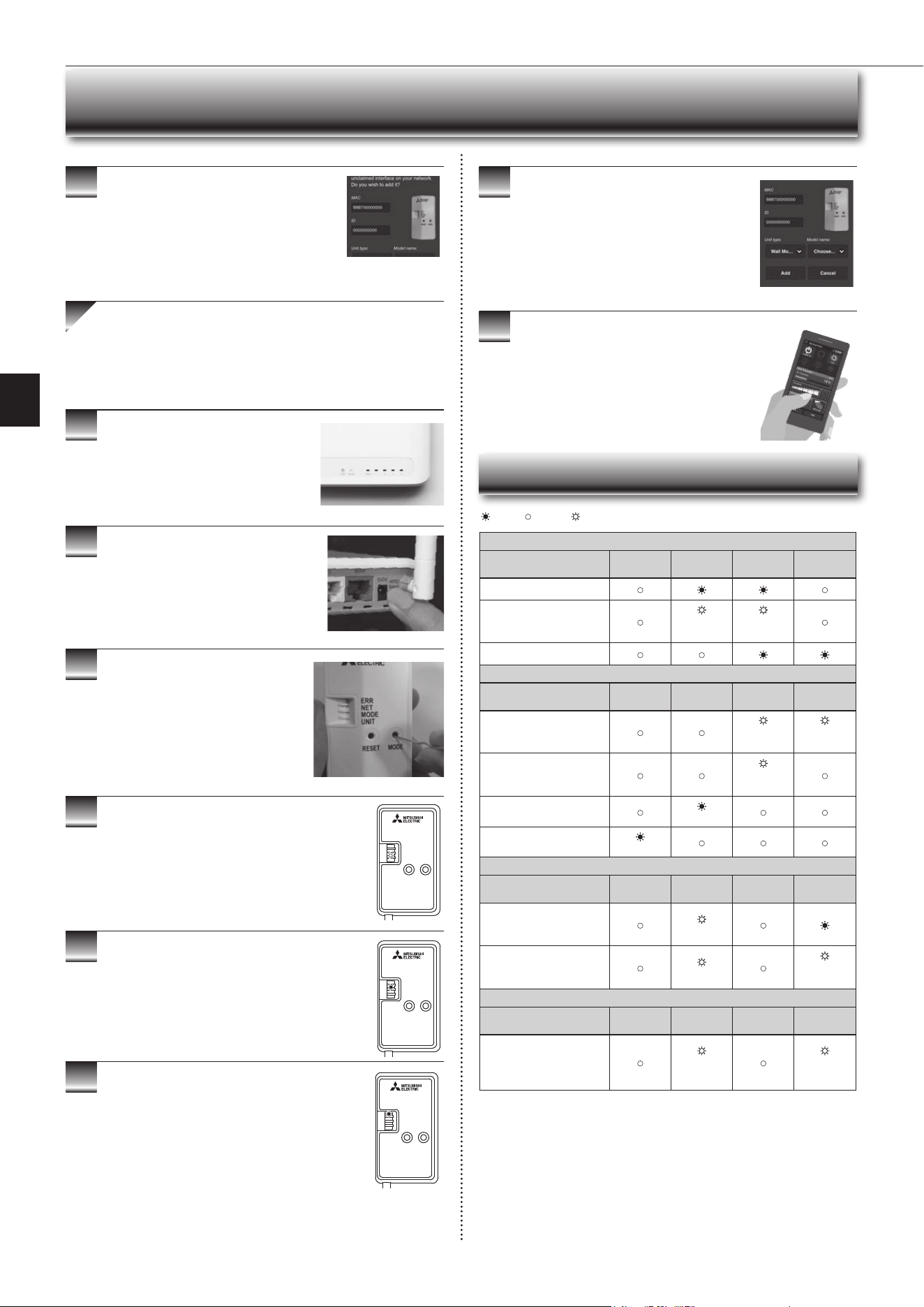
Wi-Fi INTERFACE SETTING UP (VGK TYPE ONLY)
● Software initialising
Description
ERR
(Orange)
NET
(Green)
MODE
(Orange)
UNIT
(Green)
Firmwareupdating
Firmwaredownloading
(every
second)
(every
second)
Reset to the factory default
● Wireless setting
Description
ERR
(Orange)
NET
(Green)
MODE
(Orange)
UNIT
(Green)
AccessPointMode
activated
(every5
sec)
(every5
sec)
WPS-PushModeactivated
(every
second)
Pairing process via WPS
completed
(5sec)
Pairing process via WPS
failed
(5sec)
● Connection to server in progress
Description
ERR
(Orange)
NET
(Green)
MODE
(Orange)
UNIT
(Green)
Communicatingwithserver,
and starting up indoor unit
communication
(*1)
Communicatingwithserver,
andcommunicatingwith
indoor unit
(*1)
(every5
sec)
● Normal operation
Description
ERR
(Orange)
NET
(Green)
MODE
(Orange)
UNIT
(Green)
Communicatingwithserver,
andcommunicatingwith
indoor unit
(every5
sec)
(every5
sec)
(*1)Detailsofashpattern
• Every0.5sec:Searchingforserver.
• Everysecond:RegisteringtheinformationoftheWi-Fiinterfacetoserver.
• Every5sec:Communicatingwithserver.
: ON : Flashing : OFF
Oncecompleted,theMACandIDwillbelledin
‘Addnewunit’.Select‘Add’andthencontrolyour
heat pump via Wi-Fi.
Option 2 - WPS-Push Pairing
• Please Note: The WPS and Router reset buttons may be
similar on some Routers.
•PleaseexercisecautionasresettingyourRouterwillerase
networkconguration.
CheckWi-FiandWPSareenabledonyour
Router. The connection procedure varies
depending on your Router – refer to your
Router’smanualformoreinformation.
ActivateWPSModeonyourRouter.This
willbeenabledforasetperiodallowing
approximately2minutestocompletethenext
step.Todoso,pleaserefertoyourRouter’s
manual.
Activate WPS on your Wi-Fi interface by
using a small object to press and hold the
MODEButtonfor2seconds.
When pairing process is completed on the Wi-Fi
interface,theNETLEDlightsupsolidgreenfor5
seconds.
IfERRLEDlightsuporangefor5secondsatanystage,
theremaybeaproblem;pleasestartprocessagain.
LED Pattern
ERR
NET
MODE
UNIT
RESET
MODE
ERR
NET
MODE
UNIT
RESET
MODE
ERR
NET
MODE
UNIT
RESET
MODE
En-14
Description
ERR
(Orange)
NET
(Green)
MODE
(Orange)
UNIT
(Green)
Connection to server
established, and connection to
indoor unit failed
Connection to Router failed,
and connection to indoor unit
established
Connection to Router failed,
and starting up indoor unit
connection
Connection to Router failed,
and connection to indoor unit
failed
Connection to server failed,
and connection to indoor unit
established
(*2)
Connection to server failed,
and starting up indoor unit
connection
(*2)
Connection to server failed,
and connection to indoor unit
failed
(*2)
: ON : Flashing : OFF
Wi-Fi INTERFACE SETTING UP (VGK TYPE ONLY)
Note:
• EnsurethattheRoutersupportstheWPA2-PSK(AES) encryption setting be-
fore starting the Wi-Fi interface setup.
• TheEndusershouldreadandacceptthetermsandconditionsoftheWi-Fi
service before using this Wi-Fi interface.
• To complete connection of this Wi-Fi interface to the Wi-Fi service, the Rout-
er may be required.
• ThisWi-Fiinterfacewillnotcommencetransmissionofanyoperationaldata
fromthesystemuntiltheEnduserregistersandacceptsthetermsandcon-
ditions of the Wi-Fi service.
• ThisWi-FiinterfaceshouldnotbeinstalledandconnectedtoanyMitsubishi
Electricsystemwhichistoprovideapplicationcriticalcoolingorheating.
• PleasewritedowntheinformationregardingtheWi-Fiinterfacesettingonthe
lastpageofthismanual,whenyousetupthisWi-Fiinterface.
• At the time of relocation or disposal, reset the Wi-Fi interface to the factory
default.
MitsubishiElectric’sWi-Fiinterfaceisdesignedforcommunicationto
MitsubishiElectric’sWi-Fiservice.ThirdpartyWi-Fiinterfacescannot
connecttoMitsubishiElectric’sWi-Fiservice.MitsubishiElectricisnot
responsibleforany(i)underperformanceofasystemoranyproduct;(ii)
systemorproductfault;or(iii)lossordamagetoanysystemorproduct;
whichiscausedbyorarisesfromconnectiontoand/oruseofanythird
partyWi-FiinterfaceoranythirdpartyWi-FiservicewithMitsubishiElectric
equipment.
For the latest information regarding Wi-Fi Control:
NewZealandbasedenquiriespleasevisit:www.mitsubishi-electric.co.nz/wi
Australianbasedenquiriespleasevisit:www.mitsubishielectric.com.au/wi
Onceregisteredyouwillbeabletocontrolyourheat
pumpwithyoursmartphone,tabletoronlineaccount
using an internet connection.
(For a list of compatible devices, please visit the
MitsubishiElectricwebsite).
User Manual
A copy of the user manual, terms & conditions and
privacypolicycanbedownloadedatanytimefromthe
MitsubishiElectricwebsite.
Mitsubishi Electric New Zealand
www.mitsubishi-electric.co.nz/wi
Phone:0800639434
Mitsubishi Electric Australia
www.mitsubishielectric.com.au/wi
Phone:1300728119
Register Your Heat Pump(s)
ThankyouforchoosingaMitsubishiElectricHeatPumpwithWi-FiControl.
OnceyourWi-Fiinterfaceisinstalled,eitherdownloadtheapp(searchterm:
MitsubishiWi-FiControl)orvisitourwebsitetoregisteryourheatpump(s).
*AppleandtheApplelogoaretrademarksofAppleInc.,registeredintheU.S.
andothercountries.AppStoreisaservicemarkofAppleInc.,registeredin
the U.S. and other countries.
*GooglePlayandtheGooglePlaylogoaretrademarksofGoogleLLC.
Troubleshooting
Mitsubishi Electric Wi-Fi Heat Pump Control
(*2)Detailsofashpattern
• Every 0.5 sec:
IP address setting is invalid.
MakesurethatDHCPisenabled,orcheckIPaddresssettingsoftheWi-Fi
interface.
Iftherearenoproblemsontheitemsabove,butthelampisstillashing,
pushRESETButtonformorethan14secondstoretrythepairing.
• Every second:
DNS setting is invalid.
FIXDNSsettingoftheRouter,DNSaddresssettingoftheWi-Fiinterface,
orimporttheratiowaveenvironment.
Iftherearenoproblemsontheitemsabove,butthelampisstillashing,
pushRESETButtonformorethan14secondstoretrythepairing.
• Once every 5 sec:
Notcommunicatingwithserverproperly.
PushRESETButtonfor2seconds.
• Twice every 5 sec:
Not connected to server.
CheckiftheRouterisconnectedtotheInternet.
• Three times every 5 sec:
Notcommunicatingwithserver.(Quickcommunicationerror)
PushRESETButtonfor2seconds.
Checkthefollowingrstinthecaseslistedintheabovetable.
•MakesurethatthecommunicationdistanceisnottoofarbetweentheWi-Fi
interface and the Router.
• Makesure2.4GHzisenabledondualbandRouters.
• MakesurethatWPSisworkingontheRouter.
• MakesurethattheRouteriscompatiblewiththeWi-Fiinterface.
• IfStaticIPhasbeenset-makesureitiscorrectasperRouternetworksettings.
•MakesurethattheRouterusesWPA2-PSK(AES)encryption.
•MakesurethatthenumberofconnecteddevicestotheRouterdoesnot
exceed the limit.
TheWi-FiInterfaceusesOpenSourceSoftware.ToviewtheOpen
Sourcesoftwarelicence(s),pleasegotothefollowingwebsitewhilst
connected to the Wi-Fi Interface during the Access Point mode.
http://192 .168 .11.1/ license
[Abouttrademarks]
• WPS is the connection via Wi-Fi Protected Setup.
• “Wi-Fi
®
”,“Wi-FiProtectedSetup™”,“WPA2™”aretrademarksorregistered
trademarksoftheWi-FiAlliance.
En-15
● OPERATING INSTRUCTIONS ●
Even if these items are checked, when the unit does not recover from the
trouble, stop using the air conditioner and consult your dealer.
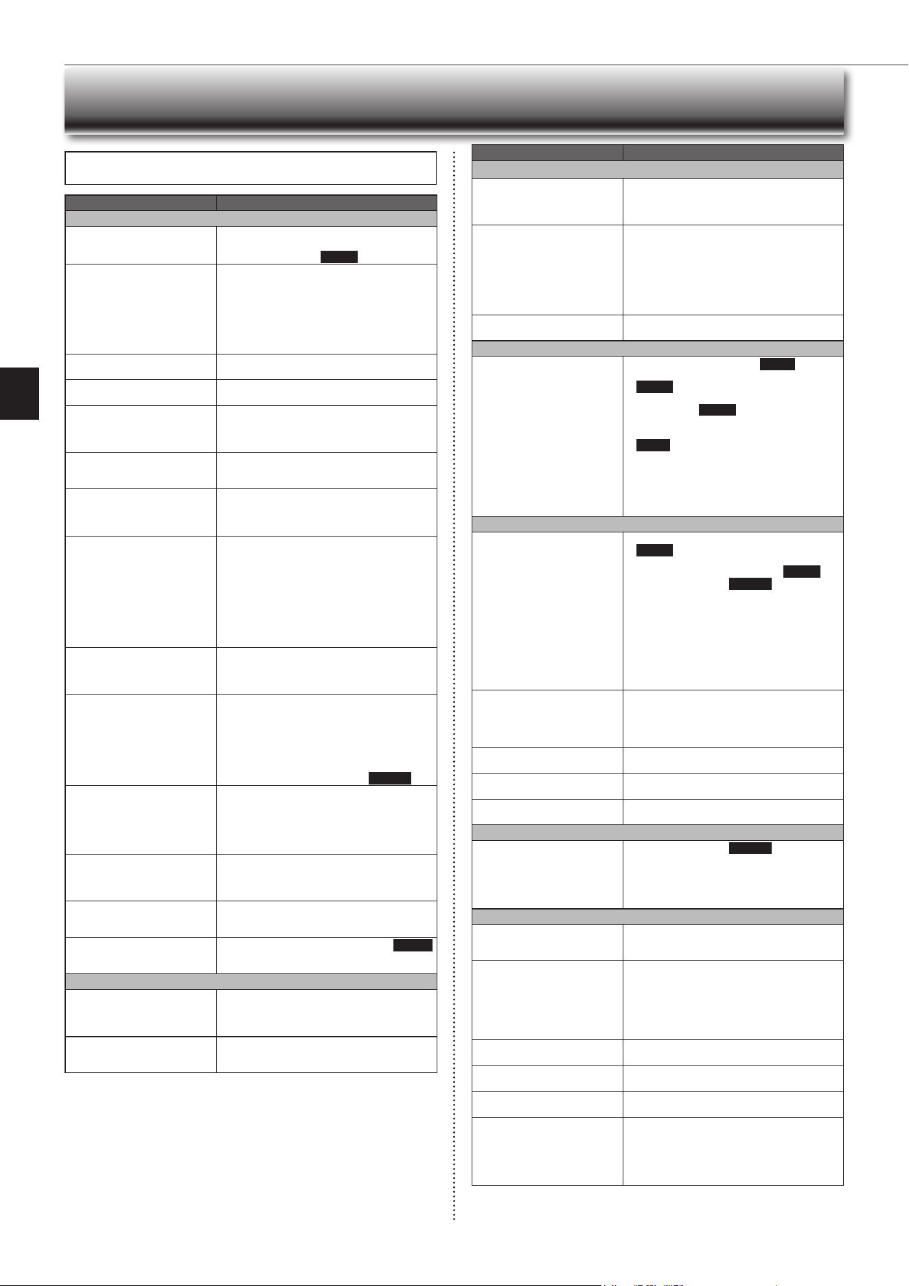
WHEN YOU THINK THAT TROUBLE HAS OCCURRED
Symptom Explanation & Check Points
Indoor Unit
The unit cannot be operated.
• Isthebreakerturnedon?
• Isthepowersupplyplugconnected?
• Is the ONtimerset?
Page 8
The horizontal vane does not
move.
• Are the horizontal vane and the vertical vane
installedcorrectly?
• Isthefanguarddeformed?
• Whenthebreakeristurnedon,thehorizontal
vanes’positionwillberesetinaboutaminute.
After the reset has completed, the normal hori-
zontalvanes’operationresumes.Thesameis
true in the emergency cooling operation.
The unit cannot be operated for
about3minuteswhenrestarted.
• This protects the unit according to instructions
fromthemicroprocessor.Pleasewait.
Mistisdischargedfromtheair
outlet of the indoor unit.
•
The cool air from the unit rapidly cools moisture
in the air inside the room, and it turns into mist.
Whitesmokeisdischargedfrom
the air inlet of the indoor unit.
• When the heating operation starts after the
defrosting operation, vapor generated from the
condensationontheheatexchangerlookslike
whitesmoke.
TheswingoperationoftheHORI-
ZONTAL VANE is suspended for
awhile,thenrestarted.
• ThisisfortheswingoperationoftheHORIZON-
TAL VANE to be performed normally.
Whenswingisselectedin
COOL/DRY/FAN mode, the
lowerhorizontalvanedoesnot
move.
• Itisnormalthatthelowerhorizontalvanedoes
not move when swing is selected in COOL/
DRY/FAN mode.
Theairowdirectionchanges
during operation.
The direction of the horizontal
vanecannotbeadjustedwith
the remote controller.
• When the unit is operated in COOL or DRY
mode,iftheoperationcontinueswithairblow-
ingdownfor0.5to1hour,thedirectionofthe
airowisautomaticallysettoupwardposition
topreventwaterfromcondensinganddripping.
• Intheheatingoperation,iftheairowtempera-
tureistooloworwhendefrostingisbeingdone,
the horizontal vane is automatically set to hori-
zontal position. Also the fan speed decreases
or the fan stops.
The operation stops for about
10minutesintheheating
operation.
• Outdoorunitisindefrost.
Since this is completed in max. 10 minutes,
pleasewait.(Whentheoutside temperatureis
toolowandhumidityistoohigh,frostisformed.)
The unit starts operation by
itselfwhenthemainpoweris
turned on, though it isn't oper-
atedwiththeremotecontroller.
• These models are equipped with an auto
restart function. When the main power is
turned off without stopping the unit with the
remote controller and is turned on again, the
unit starts operation automatically in the same
modeastheonesetwiththeremotecontrol-
ler justbeforethe shutoff of the main power.
Refer to “Auto restart function”.
Page10
Thetwohorizontalvanestouch
each other. The horizontal
vanes are in an abnormal posi-
tion. The horizontal vanes do
not return to the correct “close
position”.
Performoneofthefollowing:
•
Turnoffandonthebreaker.Makesurethehori-
zontal vanes move to the correct “close position”.
• Start and stop the emergency cooling operation
andmakesurethehorizontalvanesmovetothe
correct “close position”.
The indoor unit discolors over
time.
• Althoughplasticturnsyellowduetotheinuence
of some factors such as ultraviolet light and
temperature, this has no effect on the product
functions.
Theceilingandthewallsaround
the indoor unit have smudges.
• Itisbecausetheceilingandthewallsgetdust
in the air due to air circulation by the air condi-
tioner.
Waterleaksfromtheindoor
unit.
• Isthefrontpanelclosedaccurately?Page11
• Doeswaterowsmoothlyfromtheedgeofthe
drainhose?
Multi System
Theindoorunitwhichisnot
operatingbecomeswarmanda
sound,similartowaterowing,
is heard from the unit.
• Asmallamountofrefrigerantcontinuestoow
into the indoor unit even though it is not operat-
ing.
When heating operation is
selected, operation does not
startrightaway.
• When operation is started during defrosting of
outdoorunitisdone,ittakesafewminutes(max.
10minutes)toblowoutwarmair.
Symptom Explanation & Check Points
Outdoor Unit
The fan of the outdoor unit does
not rotate even though the com-
pressorisrunning.Evenifthe
fan starts to rotate, it stops soon.
• When the outside temperature is low during
cooling operation, the fan operates intermittently
tomaintainsufcientcoolingcapacity.
Waterleaksfromtheoutdoor
unit.
• During COOL and DRY operations, pipe or pipe
connecting sections are cooled and this causes
watertocondense.
• Intheheatingoperation,watercondensedon
theheatexchangerdripsdown.
• In the heating operation, the defrosting operation
makesiceformingontheoutdoorunitmeltand
dripdown.
Whitesmokeisdischargedfrom
the outdoor unit.
• In the heating operation, vapor generated by the
defrostingoperationlookslikewhitesmoke.
Remote Controller
The display on the remote
controller does not appear or it
is dim. The indoor unit does not
respond to the remote control
signal.
• Arethebatteriesexhausted?Page5
• Is the polarity (+, -) of the batteries correct?
Page5
• Did you press the reset button after replacing
thebatteries?
Page5
• Isthesettingofmultipleindoorunits’installation
the same as before replacing the batteries?
Page5
• Are any buttons on the remote controller of other
electricappliancesbeingpressed?
• Theindoorunitmaynotreceivethesignalwell
depending on the condition in the room. Get
close to the indoor unit and operate the remote
controller.
Does Not Cool or Heat
The room cannot be cooled or
heatedsufciently.
• Isthetemperaturesettingappropriate?
Page6
• Isthefansettingappropriate?Pleasechange
fanspeedtoHighorSuperHigh.
Page7
• Aretheltersclean?Page11
•
Is the fan or heat exchanger of the indoor unit
clean?
• Arethereanyobstaclesblockingtheairinletor
outletoftheindoororoutdoorunit?
• Isawindowordooropen?
• Itmaytakeacertaintimetoreachthesetting
temperature or may not reach that depending on
the size of the room, the ambient temperature,
andthelike.
The room cannot be cooled
sufciently.
• Whenaventilationfanoragascookerisused
in a room, the cooling load increases, resulting
inaninsufcientcoolingeffect.
• When the outside temperature is high, the cool-
ingeffectmaynotbesufcient.
The room cannot be heated
sufciently.
• Whentheoutsidetemperatureislow,theheat-
ingeffectmaynotbesufcient.
Airdoesnotblowoutsoonin
the heating operation.
• Pleasewaitastheunitispreparingtoblowout
warmair.
Poor cooling or heating perfor-
mance.
• Doyouhaveanarrangementwithyourelectric
companyforDemandResponse?
Airow
The air from the indoor unit
smells strange.
• Aretheltersclean?Page11
• Is the fan or heat exchanger of the indoor unit
clean?
• Theunitmaysuckinanodoradheringtothe
wall,carpet,furniture,cloth,etc.andblowitout
withtheair.
Sound
Crackingsoundisheard. • This sound is generated by the expansion/
contraction of the front panel, etc. due to change
in temperature.
“Burbling” sound is heard. • This sound is heard when the outside air is
absorbed from the drain hose by turning on the
rangehoodortheventilationfan,makingwater
owinginthedrainhosetospoutout.
Thissoundisalsoheardwhentheoutsideair
blowsinto thedrain hosein casethe outside
windisstrong.
Mechanicalsoundisheardfrom
the indoor unit.
• Thisistheswitchingsoundinturningon/offthe
fan or the compressor.
Thesoundofwaterowingis
heard.
• This is the sound of refrigerant or condensed
waterowingintheunit.
Hissingsoundissometimes
heard.
• Thisisthesoundwhentheowofrefrigerant
inside the unit is changed.
Heatingoperationstopsandthe
sound is heard.
• The outdoor unit is defrosting.
• Heating operationstartsafter thefroston the
outdoorunithasbeenremoved.Thiscantake
about2to10minutes.
• Crackingsound,Soundofwaterowing,Hiss-
ing sound and Whistling sound are heard.
En-16
In the following cases, stop using the air conditioner and consult your dealer.
• Whenwaterleaksordripsfromtheindoorunit.
• Whentheoperationindicatorlampblinks.
• Whenthebreakertripsfrequently.
• TheremotecontrolsignalisnotreceivedinaroomwhereanelectronicON/
OFFtypeuorescentlamp(inverter-typeuorescentlamp,etc.)isused.
• OperationoftheairconditionerinterfereswithradioorTVreception.Anampli-
ermayberequiredfortheaffecteddevice.
• When an abnormal sound is heard.
• Whenanyrefrigerantleakageisfound.
WHEN YOU THINK THAT
TROUBLE HAS OCCURRED
Symptom Explanation & Check Points
Timer
Weeklytimerdoesnotoperate
according to settings.
• Is the ON/OFFtimerset? Page 8
• Transmitthesettinginformationoftheweekly
timer to the indoor unit again. When the informa-
tionis successfullyreceived, along beepwill
sound from the indoor unit. If information fails to
bereceived,3shortbeepswillbeheard.Ensure
information is successfully received.
Page 9
• When a power failure occurs and the main
powerturnsoff,theindoorunitbuilt-inclockwill
beincorrect.Asaresult,theweeklytimermay
notworknormally.
Be sure to placetheremote controller where
the signal can be received by the indoor unit.
Page5
The unit starts/stops the opera-
tion by itself.
• Istheweeklytimerset? Page 9
Others
Thealuminumnontheedgeof
the heat exchanger is discolored
as if it is burnt.
• Thisisthecoatingresindiscoloredduetoweld-
ingheatwhen theheatexchanger wasbeing
produced.
• The operation of the air conditioner is not the
cause of the discoloration.
• It affects neither the performance of the heat
exchanger nor the use of the air conditioner.
1
OperatebyCOOLmodewiththehighesttemperature
setorFANmodefor3to4hours.Page6
• This dries the inside of the unit.
• Moistureintheairconditionercontributestofavorableconditionsfor
growthoffungi,suchasmold.
2
Press
to stop the operation.
3
Turnoffthebreakerand/ordisconnectthepowersup-
ply plug.
4
Remove all batteries from the remote controller.
When using the air conditioner again:
1
Cleantheairlter.Page11
2
Checkthattheairinletandoutletoftheindoorand
outdoorunitsarenotblocked.
3
Checkthattheearthisconnectedcorrectly.
4
Refertothe“PREPARATIONBEFOREOPERATION”,
andfollowtheinstructions.
Page5
WHEN THE AIR CONDITIONER IS NOT
GOING TO BE USED FOR A LONG TIME
Electrical work
• Provideanexclusivecircuitforthepowersupplyoftheairconditioner.
• Besuretoobservethebreakercapacity.
If you have any questions, consult your dealer.
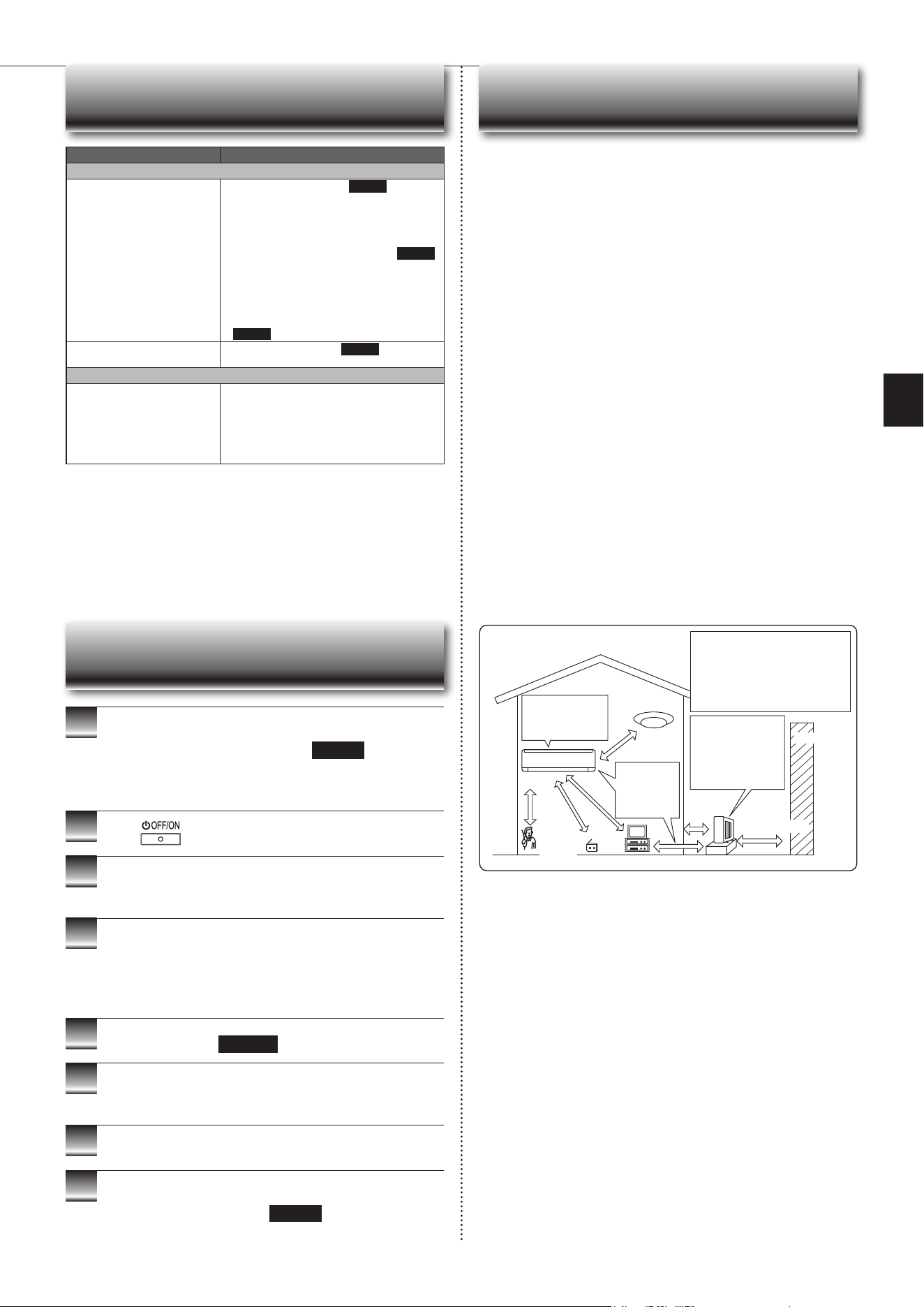
INSTALLATION PLACE AND
ELECTRICAL WORK
To prevent the effects
ofauorescentlamp,
keepasfarapartas
possible.
wall,etc.
Inverter-type
uorescentlamp
Keepaspace
to prevent
the picture
distortion or
the noise.
1m
or
more
Radio
100
mmor
more
TV
Cordless
phone or
Portable
phone
3mormore
1m
or more
The installation location of the outdoor
unitshould be at least 3m awayfrom
the antennas for TV sets, radios, etc. In
areaswherethereceptionisweak,pro-
videgreaterspacebetweentheoutdoor
unit and the antenna of the affected
device if operation of the air conditioner
interfereswithradioorTVreception.
200mmormore
For the optimum ef-
ciency
andtoextend
the life time of using,
the outdoor unit
should be installed in
awell-ventilateddry
place.
Installation place
Avoid installing the air conditioner in the following places.
• Where there is much machine oil.
• Salty places such as the seaside.
• Wheresuldegasisgeneratedsuchashotspring,sewage,wastewater.
• Whereoilissplashedorwheretheareaislledwithoilysmoke(suchascook-
ingareasandfactories,inwhichthepropertiesofplasticcouldbechanged
anddamaged).
• Wherethereishigh-frequencyorwirelessequipment.
• Wheretheairfromtheoutdoorunitairoutletisblocked.
• Where the operation sound or air from the outdoor unit bothers the house next
door.
• Themountingheightofindoorunit1.8mto2.3misrecommended.Ifitis
impossible, please consult your dealer.
• Donotoperatetheairconditionerduringinteriorconstructionandnishing
work,orwhilewaxingtheoor.Beforeoperatingtheairconditioner,ventilate
theroomwellaftersuchworkisperformed.Otherwise,itmaycausevolatile
elementstoadhereinsidetheairconditioner,resultinginwaterleakageor
scatteringofdew.
• Theindoorunitmustbeinstalledinroomswhichexceedtheoorspacespeci-
ed.Pleaseconsultyourdealer.
For Wi-Fi interface
• Do not use the Wi-Fi interface nearby the medical electrical equipment or peo-
plewhohaveamedicaldevicesuchasacardiacpacemakeroranimplantable
cardioverter-debrillator.
It can cause an accident due to malfunctions of the medical equipment or
device.
• Thisequipmentshouldbeinstalledandoperatedwithaminimumdistanceof
20cmbetweenthedeviceandtheuserorbystanders.
• DonotusetheWi-Fiinterfacenearbyotherwirelessdevices,microwaves,
cordless phones, or facsimiles.
En-17
● OPERATING INSTRUCTIONS ●
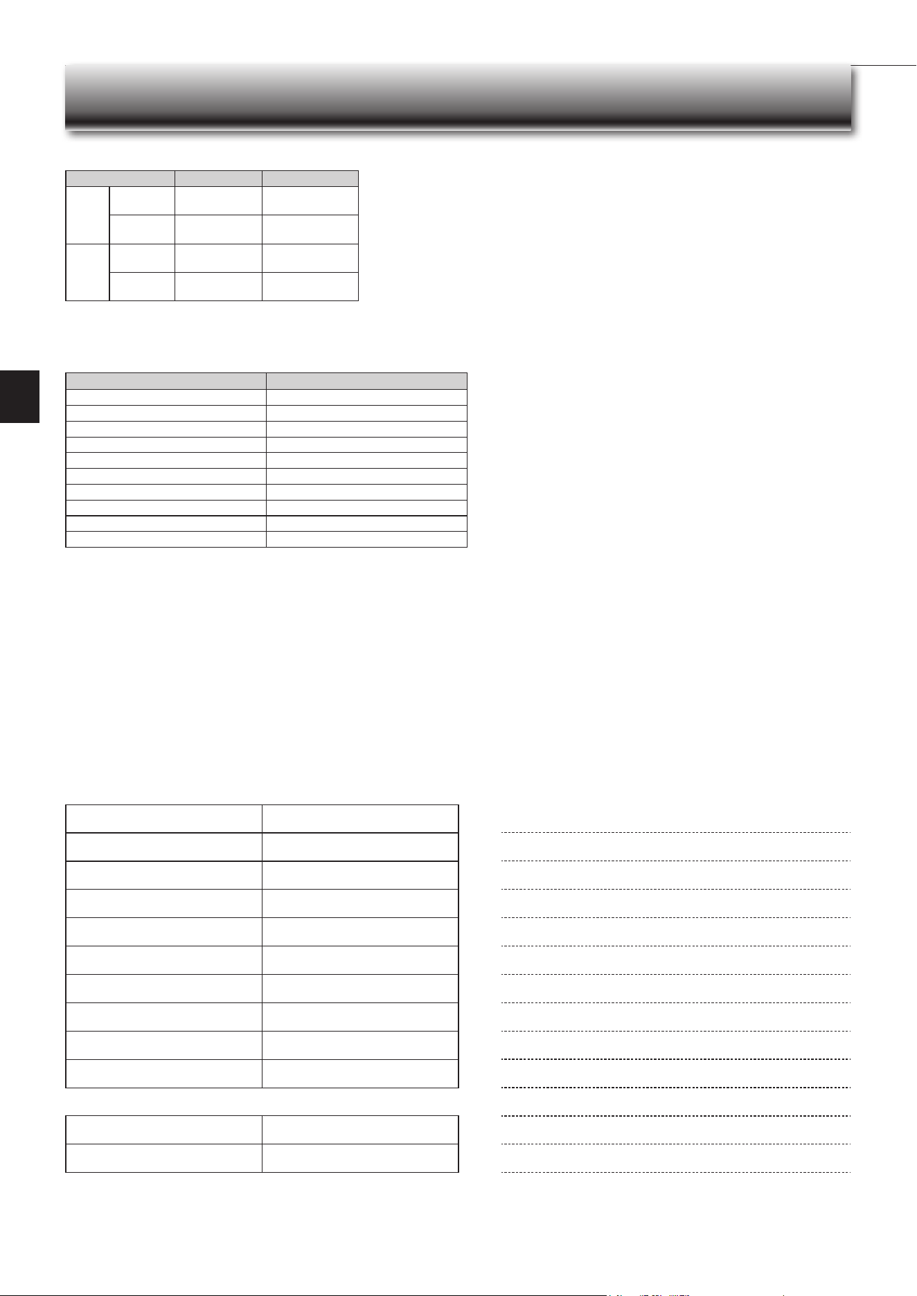
SPECIFICATIONS
Wi-Fi interface setting information
Indoor unit model name
Indoor unit serial number
Outdoorunitmodelname
Outdoorunitserialnumber
Wi-FiinterfaceMACaddress(MAC)
Wi-Fiinterfaceserialnumber(ID)
Wi-FiinterfaceSSID(SSID)
Wi-FiinterfaceKEY(KEY)
System commissioning date
Wi-Fi interface installation date
Installer contact details
Name
Telephone number
MEMO
Indoor Outdoor
Cooling
Upper limit
32°CDB
23°CWB
46°CDB
—
Lowerlimit
21°CDB
15°CWB
-10°CDB
—
Heating
Upper limit
27°CDB
—
24°CDB
18°CWB
Lowerlimit
20°CDB
—
-15°CDB
-16°CWB
Guaranteed operating range
DB : Dry Bulb
WB : Wet Bulb
Wi-Fi interface
Model MAC-578IF2-E
Input Voltage DC12.7V(fromindoorunit)
Powerconsumption MAX.2W
SizeH×W×D(mm) 73.5×41.5×18.5
Weight(g) 46(includingcable)
Transmitterpowerlevel(MAX.) 20dBm@IEEE802.11b
RF channel 1ch~13ch(2412~2472MHz)
Radio protocol IEEE802.11b/g/n(20)
Encryption AES
Authentication WPA2-PSK
SoftwareVersion XX.00

HEADOFFICE:TOKYOBUILDING,2-7-3,MARUNOUCHI,CHIYODA-KU,TOKYO100-8310,JAPAN
DG79A0D4H02