
Wisen Innovation Technical Doc. No.2026 WiSen Vision Unit (TR) - User Manual
www.wisencn.com Page - 1 - of 15
WiSen Vision Unit (TR)
User Manual
3004
Wuxi Wisen Innovation Co., Ltd.
April 2026

Wisen Innovation Technical Doc. No.2026 WiSen Vision Unit (TR) - User Manual
www.wisencn.com Page - 2 - of 15
Revision History
Rev.
Issue Date
Revisions Written By Revised By
V1.0
21/04/2026
1st Issue Xinhu Nie Dr. Yan Wu
Document Definition:
This document defines the specifications (i.e., introduction, technical features, deployment and maintenance
methods) of the WiSen Vision Unit, which is one of the key components in Wisen Low Power, Intelligent, Wireless
Sensor Network (WSN) Monitoring system. It is responsible to:
Capture high-definition images (8MP) even in ultra-low light conditions;
Issue visual (LED) and audible (buzzer) warnings on-site;
Form a time-synchronised WSN with other nodes in the system;
Transmit image data to a server via public wireless network or local WiFi / cabled network connections.
Overall, Vision Unit follows the basic procedures as shown below:
Imaging: All Vision Units capture images periodically at interval T;
Trigger Listening: The built-in radio chip listens for trigger ping signals from nodes on the same frequency
band for activation;
Activation Response: Upon activation, the unit immediately captures an image and simultaneously
activates the audible (buzzer) and visual (LED) warnings.
Scope:
Customer Site Project Managers and Engineers, Wisen Service Engineers, etc.

Wisen Innovation Technical Doc. No.2026 WiSen Vision Unit (TR) - User Manual
www.wisencn.com Page - 3 - of 15
Table of Contents
1. Product Introduction ..............................................................................................................................................- 4 -
2. System Structure Layout .........................................................................................................................................- 5 -
3. WiSen Vision Unit & Radio Features .......................................................................................................................- 6 -
4. WiSen Vision Unit Terminologies ............................................................................................................................- 8 -
5. Operation Procedures .............................................................................................................................................- 9 -
5.1.WiSen Vision Unit Location Choices ...........................................................................................................- 9 -
5.2.Deployment Procedures ............................................................................................................................- 9 -
5.3.Mounting Options ................................................................................................................................... - 11 -
6. General Maintenance and Notification ................................................................................................................. - 11 -
7. Package Information ............................................................................................................................................. - 13 -
8. Safety and Warning............................................................................................................................................... - 13 -
9. Contact ................................................................................................................................................................. - 15 -
Wisen Innovation Technical Doc. No.2026 WiSen Vision Unit (TR) - User Manual
www.wisencn.com Page - 4 - of 15
1. Product Introduction
The WiSen Vision Unit is one of the key products in our patented WisenMeshWAN® and
WISENMESHNET
®
geotechnical safety monitoring system. Working together with Wisen nodes and gateways, it
includes a high-definition 8MP black-light-grade camera with automatic flash, and an LED/buzzer warning system. The
unit is powered by primary batteries or external DC (7-32V) and uses its embedded 2G/3G/4G or WiFi/Ethernet
modules for image transmission.
This product operates using our core technology, i.e., WisenMeshWAN® and WISENMESHNET
®
Low Power, Intelligent,
Wireless Sensor Network protocol. This product satisfies the three fundamental identities of the system:
A. Network Life Span: to maximise battery life across the mesh network as a whole;
B. Network Data Arrival Rate: to minimise data packet loss;
C. Single Node Environmental Coverage: to maximise radio coverage.
Our product has a minimum IP68 rate and is designed to work in a tough environment. It is small in size, reliable in
performance, easy for maintenance, and has strong immunity to radio-interference.
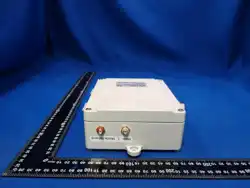
Figure. WiSen Vision Unit Overview in Photos.
Wisen Innovation Technical Doc. No.2026 WiSen Vision Unit (TR) - User Manual
www.wisencn.com Page - 5 - of 15
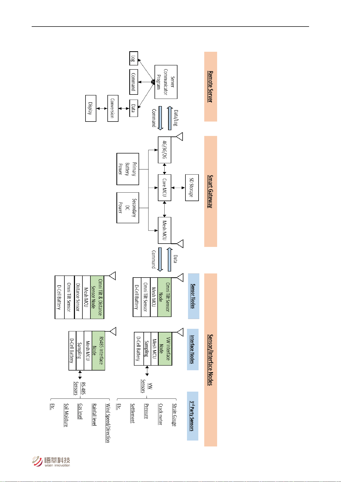
2. System Structure Layout
Figure. System Structure Layout.

Wisen Innovation Technical Doc. No.2026 WiSen Vision Unit (TR) - User Manual
www.wisencn.com Page - 6 - of 15
3. WiSen Vision Unit & Radio Features
WiSen Vision Unit Features:
Basics
Primary Battery Power
Qty. x 4 (3.6V Lithium primary D-Cell ER34615)
Secondary DC Power
7 - 32VDC @ Min. 2A
4G Network Stop Voltage
2.1V
Local Storage
≥ 100 days @ T=60min (2600 Images)
Dimension (L x W x H)
180 x 140 x 60mm
Weight
≤ 2.6kg
Cable Gland
Qty. 1 x EMC-CMA20 for Camera & LED/Buzzer;
Qty. 1 x EMC-CMA14 for external DC input
External Camera – High Definition 8MP / Full Colour / Black Light Grade / Waterproof
Image Resolution
3840 x 2160
Image Compression
JPEG
HD Lens
5.0mm
Angle of View
Horizontal 93° / Vertical 50°
Camera Flash Range
White flash, 20-30m+ in complete darkness
Warm-up Time
48s
Operating Temperature
-20°C to 65°C
IP Rating
IP68
Enclosure Material
Aluminium alloy
External LED / Buzzer On-Site Warning
Buzzer Volume
≥ 90dB @ 10cm
LED Colours
Off / Green / Yellow / Orange / Red

Wisen Innovation Technical Doc. No.2026 WiSen Vision Unit (TR) - User Manual
www.wisencn.com Page - 7 - of 15
Basics
Warning Pattern
Yellow LED + buzzer beeping once per second (default)
Operating Modes
Mode 1 (Default)
Photo automatically taken at every T (3min to 24hrs)
Mode 2 (Passive)
Photo taken only upon command
Mode 3 (Trigger)
Photo taken when any node in trigger mesh system is
triggered
External Interface
Wireless Module
4G Daughter Board (default) or 2.4GHz WiFi Daughter
Board
Wired Port
RS232 on Board / Ethernet Daughter Board
WSN Interface
Mesh Wireless Interface
Wisen Protocol
Standard System Parameter
Temperature
Range: -40 to 85°C; Accuracy: ±0.1°C; Resolution: 0.1°C
Humidity
Range: 0 to 100%RH; Accuracy: ±1.5%RH
Voltage
Accuracy: ±0.1V
Industrial Standard
Casing and Painting Materials
Aluminium-Alloy Die Castings 12 (Epoxy Polyester Powder
Coating)
IP Rating
≥ IP67
Operating Temperature
-40 to 85°C
Wisen Innovation Technical Doc. No.2026 WiSen Vision Unit (TR) - User Manual
www.wisencn.com Page - 8 - of 15
4G General Features:
Frequency Bands LTE-TDD B41
LTE-FDD BB2/B4/B5
B12/B13/B25/B26/B66
UMTS/HSPA+ B1/B2/B4/B5/B6/B8/B19
GSM/GPRS/EDGE 850/900/1800/1900 MHz
Supply Voltage 3.4V ~ 4.2V, Typ: 3.8V
Control Via AT Commands
Operation Temperature -40℃ ~ +85℃
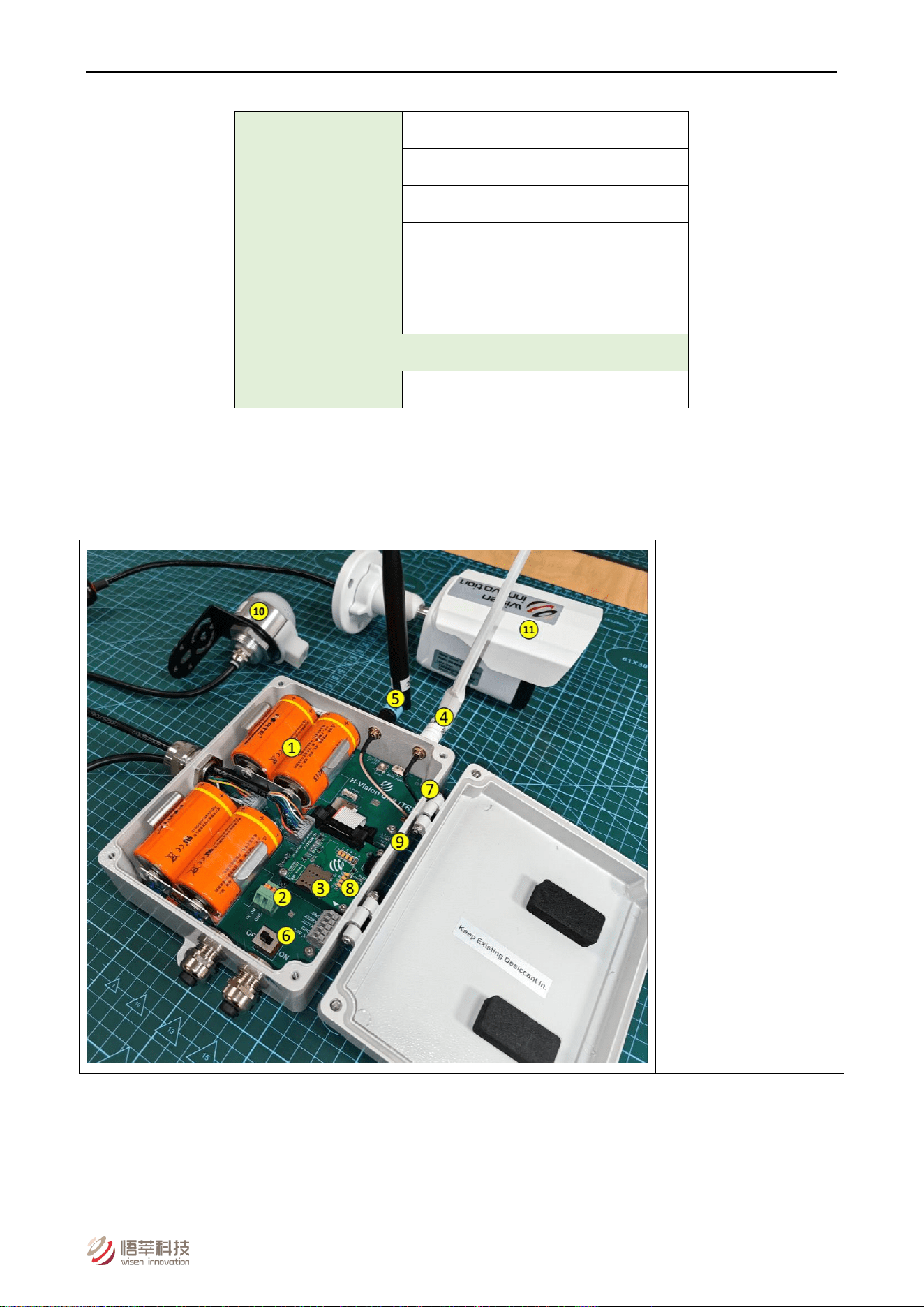
4. WiSen Vision Unit Terminologies
(1) Internal Battery
(2) External DC Terminal
(3) SIM Card
(4) 4G Antenna
(5) Mesh Antenna
(6) Power Switch
(7) Mesh LEDs
(8) 4G LEDs
(9) NET LED
(10) Warning LED/Buzzer
(11) X1 Camera
Figure. Vision Unit Terminologies.
Wisen Innovation Technical Doc. No.2026 WiSen Vision Unit (TR) - User Manual
www.wisencn.com Page - 9 - of 15
5. Operation Procedures
5.1.WiSen Vision Unit Location Choices
Location: There are two fundamental considerations that are used by Wisen to identify available location for a WiSen
Vision Unit:
1) Firstly, the mesh coverage is the primary factor to be considered. It is vital to arrange the wireless mesh
topology so that all the nodes in the system are connected. The recommended location of a Vision Unit is
next to the gateway, where wireless trigger pings from nodes can always be received;
2) Secondly, 2G/3G/4G coverage (or equivalent when WiFi, Ethernet modules are used) in the site must be
available to ensure communication between a Vision Unit and a remote server. The simplest way to check
the signal availability on site will be to use a mobile phone having the same service operator as that of the
Vision Unit;
3) Camera placement: avoid nearby objects that may reflect flash; avoid facing strong light sources.
5.2.Deployment Procedures
1) Open packaging, take out unit, open lid;
2) Insert 4 x ER34615 batteries (observe polarity);
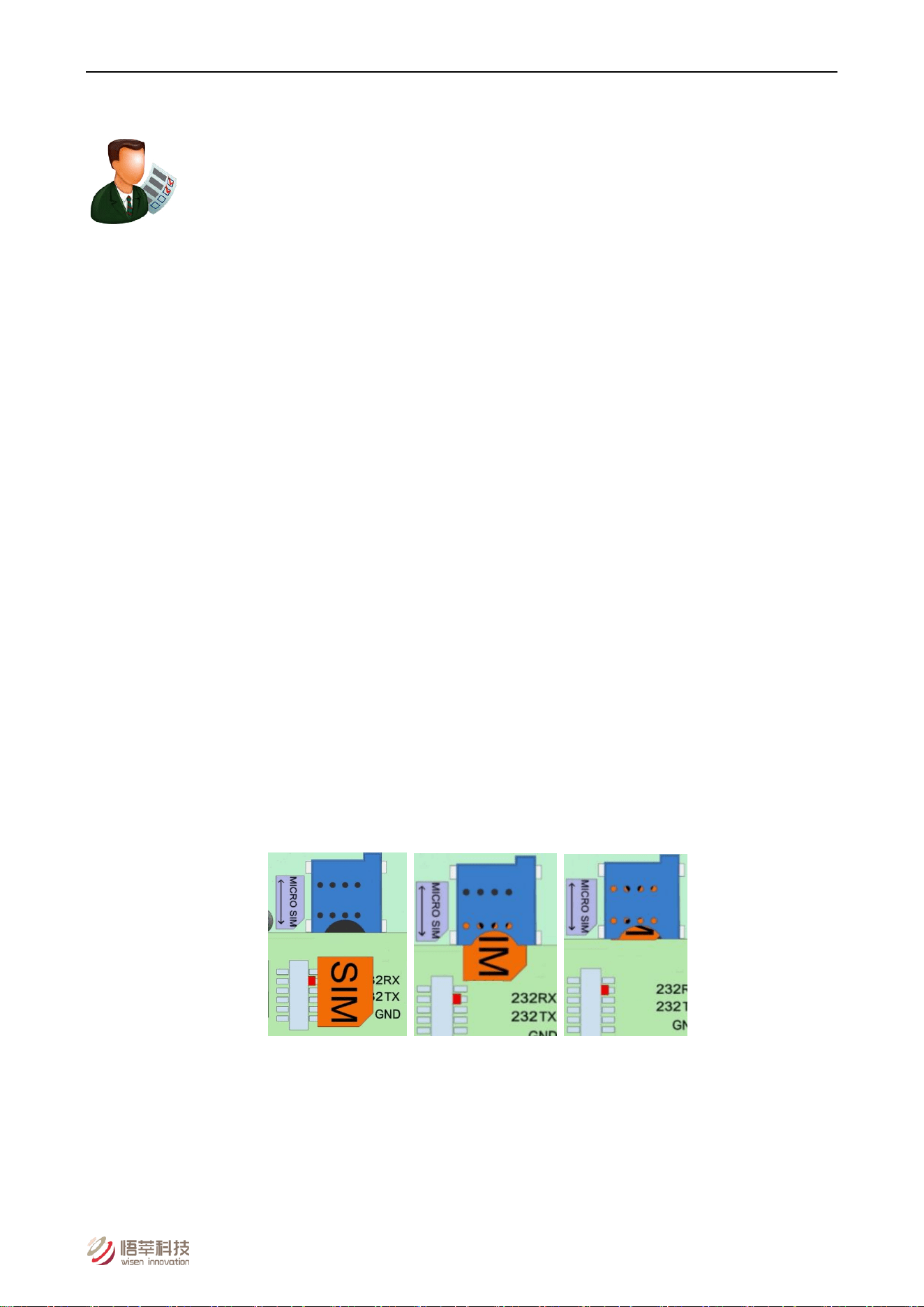
3) Insert Micro SIM card into 4G daughter board (golden chip facing PCB, cut-corner outward);
Figure. SIM Card Insertion.
Note:
A. SIM Card Installation: To insert/replace the SIM card, you MUST Turn off the power!
B. Push the SIM card all the way into the SIM holder until you hear a click, which means a secured
insertion is made.
Wisen Innovation Technical Doc. No.2026 WiSen Vision Unit (TR) - User Manual
www.wisencn.com Page - 10 - of 15
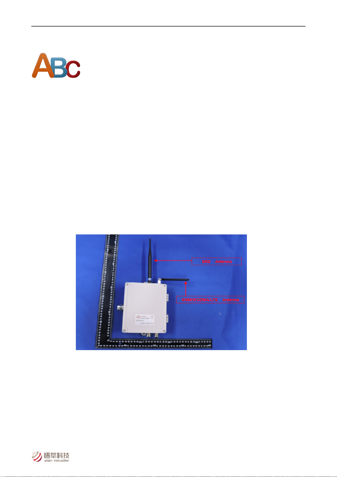
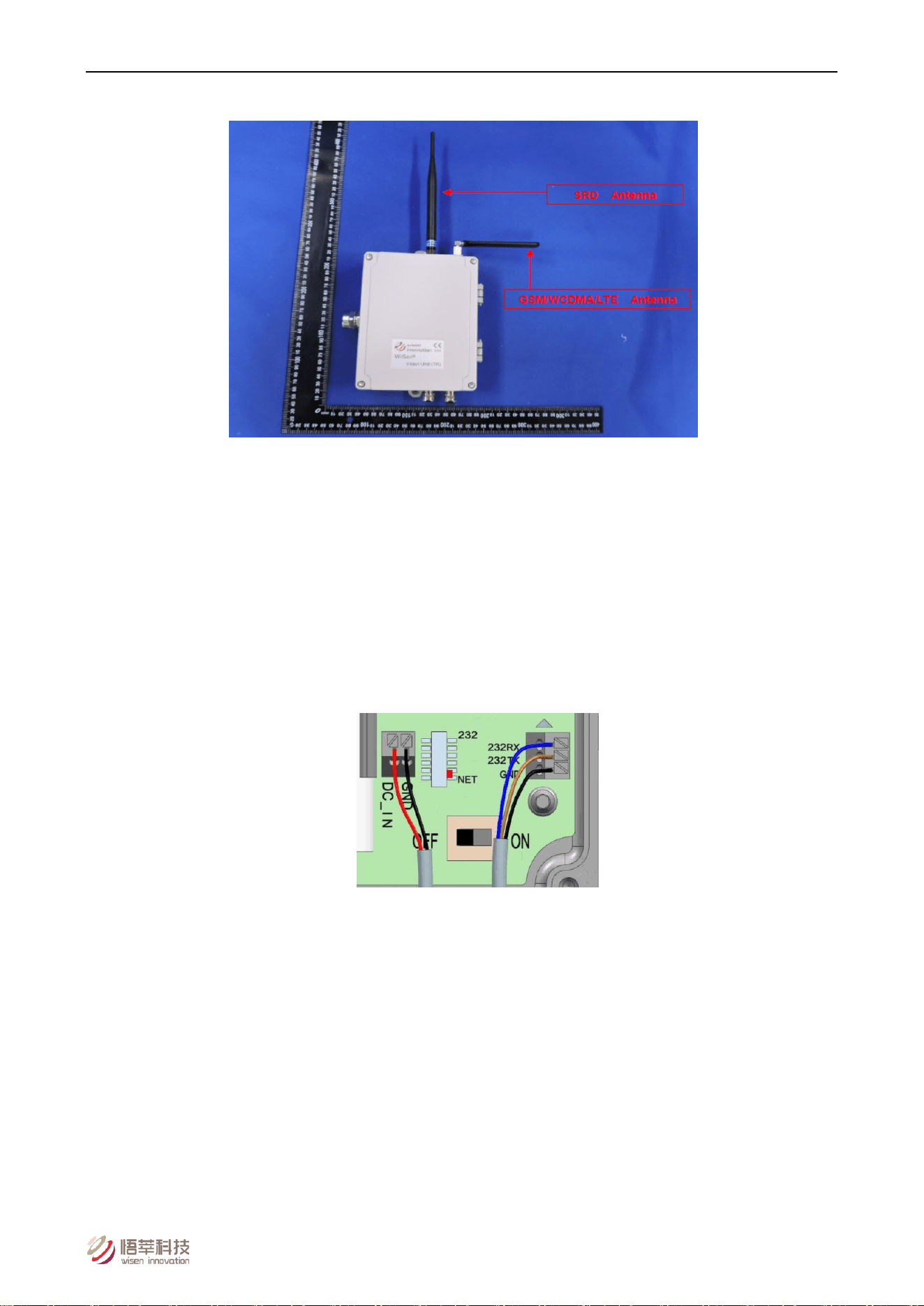
4) Install antennas (mesh and 4G) firmly;
Figure. Mesh Antenna (left) and 2G/3G/4G Antenna (right).
5) Connect external camera:
Orange -> R-; White -> R+; Green -> T-; Blue -> T+; Black -> GND; Red -> VCC
6) Connect LED/Buzzer (if used):
Green -> G; Yellow -> Y; Red -> R; White -> Buzzer; Black -> VCC
7) Connect external DC power if needed (DC_IN and GND terminals);
Warning: incorrect power connection will cause serious damage.
Figure. DC Cable & RS232 Connections.
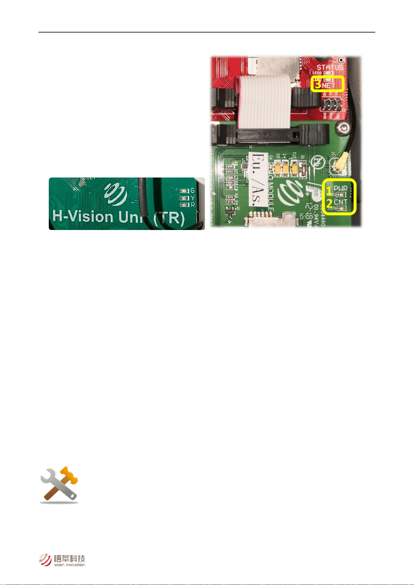
8) Power on a Vision Unit: observe LED sequence: Red, Yellow, Green flash once each, then warning colour
flashes 3 times with buzzer;
9) On the 4G daughter board, the LED flashing sequence is as shown below:
A. “PWR” (power supply) turns on;
B. “CNT”: slow flashes (meaning searching for a valid network), then quick flashes (meaning registering to
the found network);
C. On the Vision Unit main board, “NET” LED turns to solid green (meaning a successful connection to the
cloud sever was established).
Wisen Innovation Technical Doc. No.2026 WiSen Vision Unit (TR) - User Manual
www.wisencn.com Page - 11 - of 15
It overall takes about 30-40s to connect to a server.
Figure. Mesh LED and 4G Daughter Board LEDs.
10) After initial 2 intervals (3min each), unit reverts to configured T;
ONLY if connection to server is available, the 2nd Time Interval takes one photo and sends back to
the server.
11) Tighten lid and cable glands;
12) Validate image data on Wisen Visualisation Platform.
5.3.Mounting Options
Mount unit securely on pole or wall using fixing bracket. Ensure camera has clear view of target area and is not
obstructed.
6. General Maintenance and Notification
1) Once the Vision Unit is installed and working, please do not interfere with it (e.g., moving around, power cycling)
unless it is absolutely necessary;

Wisen Innovation Technical Doc. No.2026 WiSen Vision Unit (TR) - User Manual
www.wisencn.com Page - 12 - of 15
2) The Vision Unit relies on radio signals to communicate with the nodes. It must be wirelessly reachable by the
nodes and please ensure that it is not covered by any materials, which would block the radio signals, for example,
chicken wire, aluminum sheet hoardings, etc.;
3) If no data is received from the Vision Unit, then please carry out investigations in the following two stages:
A. Remote Inspection of historical data, to identify:
a) Whether the heart-beat message has been sent back successfully at each time interval;
b) Whether the voltage in the heart-beat message is as expected, if not, please check the batteries;
c) Whether the signal strength has become significantly weaker, if yes, please check the antenna has been
screwed on firmly;
d) Whether the SIM card contract is valid and that payment is paid up to date.
B. On-site Inspection: if all above are good, please arrange for an on-site inspection to check:
a) Whether the Vision Unit has visible external damage;
b) Please check that the 2G/3G/4G and Mesh antennas have not been screwed to the wrong connectors;
c) Whether the antenna is bent or damaged and it is not blocked by new construction, e.g., hoardings;
d) Whether any live and high voltage cable is directly hanging right next to the Vision Unit 4G antenna; [If
so, remove and keep a minimum 0.5m distance];
e) If an external DC power is used on a Vision Unit, then ensure it is NOT shared with any other heavy
machinery, which will cause a power surge;
f) Whether any connectors are loose.
Notices
:
i. Case One: If any improvement has been made from the list above, please inspect the data from the Wisen
Visualisation Platform;
ii. Case Two: If all the actions from the list above have not cured the problem, please do take high quality photos
during the site inspection and share with the Wisen support team for further consultancy (if needed).
Wisen Innovation Technical Doc. No.2026 WiSen Vision Unit (TR) - User Manual
www.wisencn.com Page - 13 - of 15
7. Package Information
Standard:
No.
Items
Dimension (mm) Qty.
1)
WiSen Vision Unit
200x180x60 1
2)
Wisen X1 Camera (with 1m cable)
68x68x174 1
3)
Mesh Antenna
200 1
4)
4G Antenna
200 1
5)
LED/Buzzer Warning Unit (with cable)
- 1
6)
Cap-Hex-Head Screw (lid)
M4x20 4
7)
Cap-Hex-Head Screw (back)
M6x14 4
8)
User Manual*
Downloadable from Wisen Visualisation Platform
9)
Inspection Report*
8. Safety and Warning
Warning: Please read the following instructions carefully.
1)Operation Safety
Before taking any action, please read all the information provided carefully, and keep the guidance
documents safe;
Ensure that any procedure and installation are correctly carried out. This product has been designed to a
Wisen Innovation Technical Doc. No.2026 WiSen Vision Unit (TR) - User Manual
www.wisencn.com Page - 14 - of 15
certain water-proof level. However, it is vulnerable to water ingress when the lid is open or if the cable gland
has not been sealed properly.
2)Electrical Safety
To install the batteries into a holder, please follow the “+” (positive) and “-” (negative) signs in any Wisen
product. Wrong orientation of a battery could potentially cause unit damage. Notice: The orientation of
battery can vary among products.
When disconnecting the battery, please take special care NOT to apply excessive force, otherwise the
battery holder and the nearby circuitry may be damaged.
3)Warning
Notice:
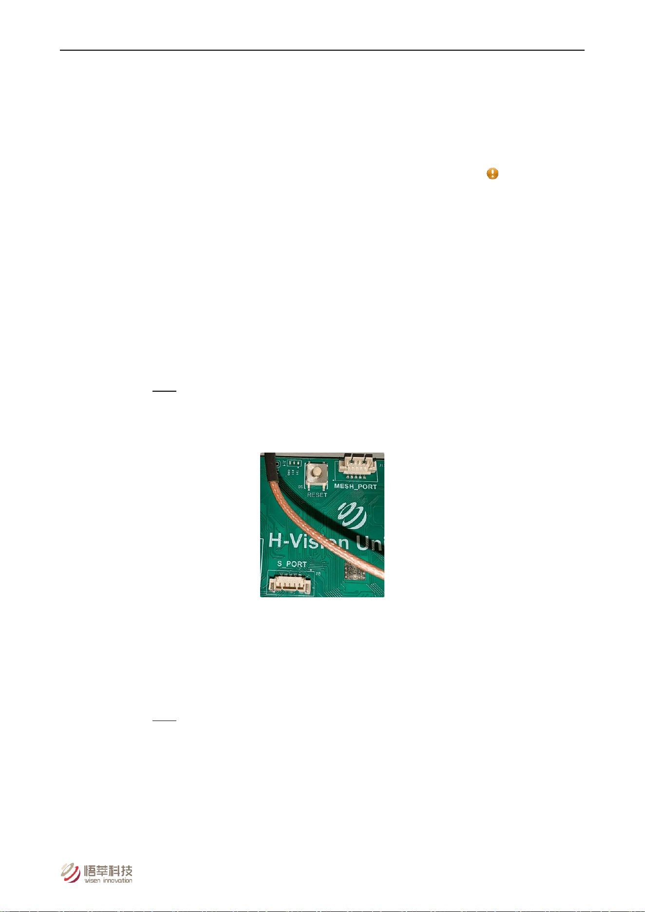
It should be ensured that only maintenance personnel is allowed to open the Vision Unit to:
A. Access both local firmware upgrade ports.
Note: Local firmware upgrade ports contain two parts:
a. S_PORT, for Vision Unit control;
b. MESH_PORT, for Mesh network control.
Figure. S_PORT, MESH_PORT and Reset Button.
B. Use the Reset button.
C. Turn on or off the power switch;
D. Replace TF card.
Note: TF storage card must NOT be removed without notifying Wisen Support team first.
In case, if TF storage card is indeed damaged for some reason during usage, please contact Wisen
Support team, we will guide a user to the official website link corresponding to the industrial
grade TF storage card. Or we will send out a new TF storage card to the user for replacements.
This product must not be disassembled under any circumstances, to do so will void the warranty and may
leave the product in a dangerous state;

Wisen Innovation Technical Doc. No.2026 WiSen Vision Unit (TR) - User Manual
www.wisencn.com Page - 15 - of 15
If all the above are not followed, the manufacturer cannot be held responsible for any damage and injury
caused to the users.
4)Caution
Danger of explosion if battery is the incorrectly specified type. ONLY use the type recommended by the
manufacturer. Observe any warnings specified by the battery manufacturer.
When disposing of the batteries, please contact your local authorities or dealer and ask for the correct
method of disposal.
9. Contact
- Wuxi Wisen Innovation Co., Ltd. Website: www.wisencn.com
- Email: [email protected]
- FCC Warning
- This device complies with part 15 of the FCC Rules. Operation is subject to the following two conditions: (1) This
device may not cause harmful interference, and (2) this device must accept any interference received, including
interference that may cause undesired operation.
-
- Any Changes or modifications not expressly approved by the party responsible for compliance could void the
user's authority to operate the equipment.
-
- Note: This equipment has been tested and found to comply with the limits for a Class B digital device, pursuant
to part 15 of the FCC Rules. These limits are designed to provide reasonable protection against harmful
interference in a residential installation. This equipment generates uses and can radiate radio frequency energy
and, if not installed and used in accordance with the instructions, may cause harmful interference to radio
communications. However, there is no guarantee that interference will not occur in a particular installation. If this
equipment does cause harmful interference to radio or television reception, which can be determined by turning
the equipment off and on, the user is encouraged to try to correct the interference by one or more of the
following measures:
-
- -Reorient or relocate the receiving antenna.
- -Increase the separation between the equipment and receiver.
- -Connect the equipment into an outlet on a circuit different from that to which the receiver is connected.
- -Consult the dealer or an experienced radio/TV technician for help.
-
- This equipment complies with FCC radiation exposure limits set forth for an uncontrolled environment. This equipment
should be installed and operated with minimum distance 20cm between the radiator & your body.
End of User Manual