1
Owner’s Manual
Este manual está disponible en español en la página de Eaton:
Tripplite.Eaton.com/support
Ce manuel est disponible en français sur le site Web de Eaton :
Tripplite.Eaton.com/support
Dieses Handbuch ist in deutscher Sprache auf der Eaton-Website verfügbar:
Tripplite.Eaton.com/support
Questo manuale è disponibile in italiano sul sito web di Eaton:
Tripplite.Eaton.com/support
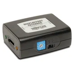
Purchased product
may differ from image.
Models:
B127A-1A1-BDBD
B127A-1A1-BDBH
B127A-110-BD
B127A-111-BDTD
DisplayPort over Cat6 4K
Extender Kits and Receiver
with Repeater

2
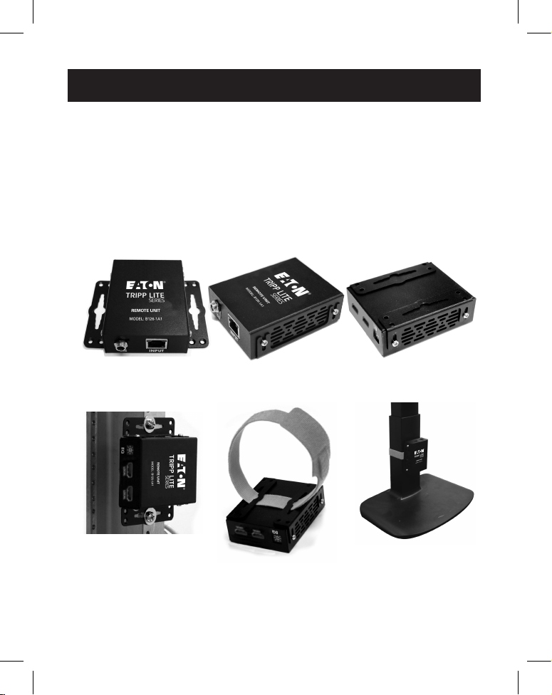
Package Contents
Optional Accessories
Product Features
B127A-1A1-BDBH
• DisplayPort 1.2a to HDMI over Cat6 Power over Cable (PoC) Extender
Kit
• Extends a 4K x 2K (3840 x 2160) @ 60 Hz signal, as specied in HDMI
2.0, up to 230 ft. (70 m) from the source.
• Built-in local HDMI port supports 4K @ 60 Hz signal
• Real-time video compression and decompression technology
• Supports up to 7.1-channel surround sound audio
• Receiver features built-in Toslink port for audio extraction function
• Transmitter
• Receiver
• External Power Supply (Input: 100-240V, 50/60 Hz, 0.6A;
Output: 24V 1A)
• (4x) International Plugs*
• Mounting Hardware
• Owner's Manual
*Includes NEMA 1-15P (North America), CEE 7/16 Schuko (Europe), BS 1363 (U.K.) and AS/NZS 3112 (Australia) plugs
• N202-Series Cat6 24 AWG Solid-Wire Patch Cables
• P569-XXX-CERT or P568-XXX-2A Series High-Speed HDMI Cables
• P580-Series DisplayPort Cables with Latches
• B127A-010-H Signal Booster

3
Product Features
• Compatible with B127A-010-H signal booster (sold separately) to
increase transmission distance up to 400 ft. from the source
• HDCP 2.2 compatible
• Plug-and-play - no software or drivers required
• Supports bi-directional IR and USB 1.1 function by DIP switch selection
• Includes mounting hardware that enables both the local transmitter
and remote receiver units to be wall-mounted, rack-mounted or pole-
mounted
B127A-1A1-BDBD
• DisplayPort 1.2a over Cat6 extender and receiver kit with Power over
Cable (PoC)
• Extends a 4K x 2K (3840 x 2160) @ 30 Hz signal up to 230 ft. (70 m)
from the source
• Built-in local HDMI port supports 4K x 2K (3840 x 2160) @ 30 Hz
resolutions
• Real-time video compression and decompression technology
• Supports up to 7.1-channel surround sound audio
• Compatible with B127A-010-H signal booster (sold separately) to
increase transmission distance up to 400 ft. from the source
• Receiver features a Toslink port for audio extraction
• Supports DisplayPort 1.2a and is HDCP 2.2 compatible
• Plug-and-play - no software or drivers required
• Supports bi-directional IR and USB 1.1 function by DIP switch selection
• Includes mounting hardware that enables both the local transmitter
and remote receiver units to be wall-mounted, rack-mounted or pole-
mounted

4
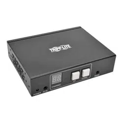
B127A-110-BD
• DisplayPort 1.2a over Cat6 daisy-chainable receiver with repeater and
Power over Cable (PoC)
• Extends and repeats a 4K x 2K (3840 x 2160) @ 30 Hz signal up to
230 ft. (70 m) from the source in daisy-chain installations
• Can be daisy-chained up to 4 times via additional B127A-110-BD
units, each link capable of adding an additional 230 ft. of transmission
distance for a total of 920 ft.
• Real-time video compression and decompression technology
• Features a Toslink port for audio extraction
• Supports DisplayPort 1.2a and HDCP 2.2
• Plug-and-play – no software or drivers required
• Supports up to 7.1-channel surround sound audio
• ncludes mounting hardware that enables the unit to be wall-mounted,
rack-mounted or pole-mounted
• Increases the maximum transmission distance to 1,090 ft. with the
addition of a B127A-010-H signal booster (sold separately) to the rst
link of a daisy-chain installation
Note: The signal booster will only work when used in the rst link of the daisy-chain
installation.
Package Contents

5
B127A-111-BDTH
• DisplayPort 1.2a over Cat6 daisy-chainable extender kit with Power
over Cable (PoC)
• Extends and repeats a 4K x 2K (3840 x 2160) @ 30 Hz signal up to
230 ft. (70 m) from the source in daisy-chain installations
• Can be daisy-chained up to 4 times via additional B127A-110-BD
units, each link capable of adding an additional 230 ft. of transmission
distance for a total of 920 ft.
• Built-in local HDMI port supports 4K x 2K (3840 x 2160) @ 30 Hz
resolutions
• Bi-directional PoC technology allows the external power supply to
be plugged in at either the transmitter or receiver end to power the
whole installation
• Real-time video compression and decompression technology
• Features a Toslink port for audio extraction
• Supports up to 7.1-channel surround sound audio
• Supports DisplayPort 1.2a and HDCP 2.2
• Plug-and-play – no software or drivers required
• Includes mounting hardware that enables the receiver unit to be wall-
mounted, rack-mounted or pole-mounted
• Increases the maximum transmission distance to 1,090 ft. with the
addition of a B127A-010-H signal booster (sold separately) to the rst
link of a daisy-chain installation
Note: The signal booster will only work when used in the rst link of the daisy-chain
installation.
Package Contents

6
Disclaimer
Before installation, check the following settings of your source(s)
and TV/monitor(s):
1. Set to display 60 Hz. Double-check factory settings, in case the
default is set to a lower frequency (Hz) than advertised.
2. Ensure the input setting of your monitor is set at HDMI 2.0 or
DisplayPort 1.2a. Some displays may have default setting at
HDMI 1.4.
Note: This is only important for the B127A-1A1-BDBH model; the
B127A-1A1-BDBD, B127A-110-BD and B127A-111-BDTD will need DP 1.2a
settings.
3. Check if the Ultra HD (UHD) Deep Color setting is enabled on your
TV/monitor. Conrm with your TV/monitor manufacturer which HDMI
ports support UHD Deep Color.
Note: Only for the B127A-1A1-BDBH model.
4. Check the USB/IR DIP switch, as the default setting is set to “IR”.
Notes: Only for the B127A-1A1-BDBH and B127A-1A1-BDBD models. The
B127A-111-BDTD and B127A-110-BD units do not have IR/USB ports or a DIP
switch.To connect a local monitor to your installation, the UHD Deep Color setting
may need to be disabled on your local TV/monitor (depending on the make/
model) to achieve 4K/60 Hz resolution.
7
Mounting Instructions
The B127A-1A1-BDBH, B127A-1A1-BDBD, B127A-110-BD and
B127A-111-BDTD include mounting hardware that allows for a variety
of mounting methods. The following images illustrate how the included
mounting brackets can be attached for dierent installations.
Note: The model shown in the below images is for illustrative purposes only. Your
product may vary by model number, size or port orientation. The mounting options
for all over IP units are the same.
19” Rack-Mount Pole-Mount
Wall-Mount
8
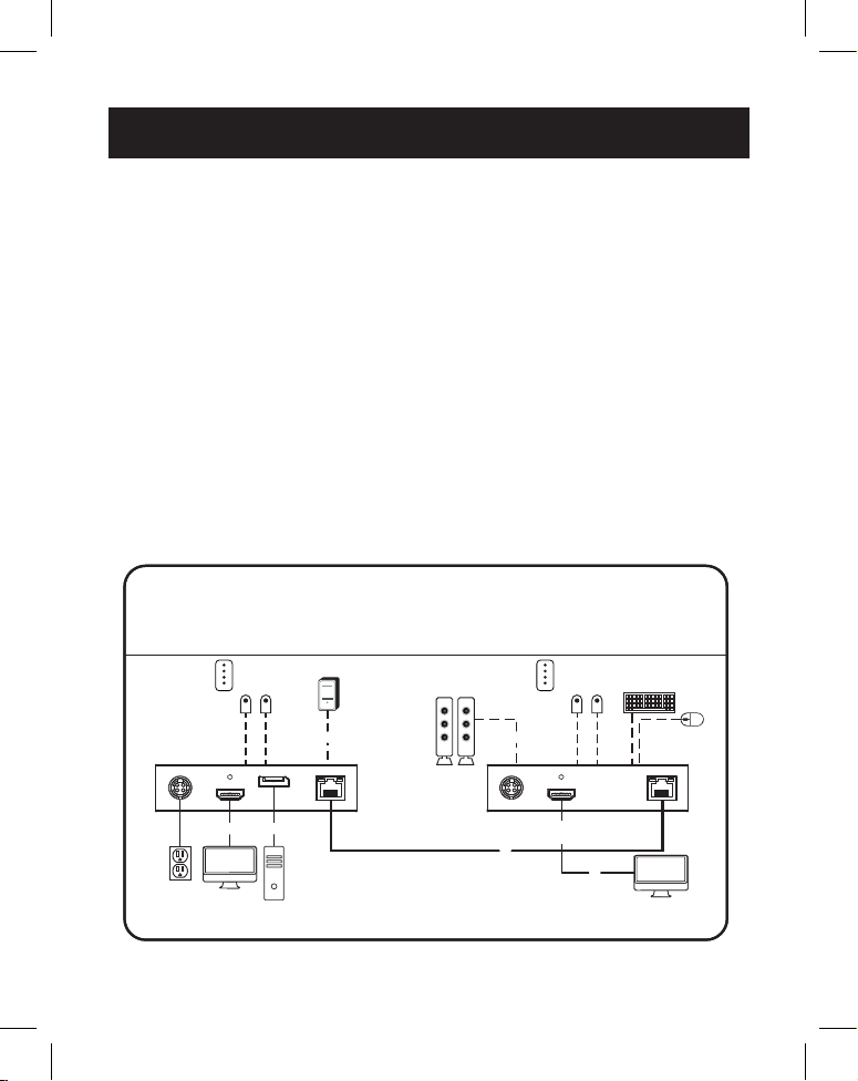
Standard Extender Kit Installation
Model B127A-1A1-BDBH
Notes:
1) Test to ensure the entire installation works properly before pulling cables through
ceilings/walls.
2) To achieve maximum distance and performance, use 24 AWG solid wire Cat6
cable. Using stranded-wire Cat6 cable or cable with a gauge (AWG) size higher
than 24 AWG will result in shorter extension distance. Higher gauge cabling, such
as 26 AWG, has a more limited transmission capability than lower gauge cabling.
N202-Series Cat6 cables are made with 24 AWG solid-wire cabling.
3) The installation diagram shows a B127A-1A1-BDBH unit.
4) External power is not required for remote receiver units due to Power over Cable
(PoC) technology incorporated in the transmitter units.
5) If there are issues with a ickering video signal after installation, remove the Cat6
cable and try another one, either the same length or shorter. If the icker persists,
change the host computer's resolution to 1920 x 1080 to see if the image itself is
stable.
B127A-1A1-BDBH extender kit
LOCAL / TRANSMITTER REMOTE / RECEIVER
Micro-USB cable
Toslink cable
Up to 230 ft. Cat6 solid cable at 4K/60 Hz
Up to 15 ft. DisplayPort cable at 4K/60 Hz
Up to 15 ft. HDMI 2.0 cable at 4K/60 Hz
DisplayPort
Source
Monitor
TV
Up to 230 ft. (70 m) at 4K/60 Hz
IR Control
Pad
IR
SENSOR
IR Control
Pad
IR
SENSOR
USB
MOUSE
USB
KEYBOARD
B127A-1A1-BDBH extender kit
Up to 230 ft. Cat6 solid cable at 4K/60 Hz
Micro USB cable
Up to 15 ft. DisplayPort cable at 4K/60 Hz
Toslink cable
Up to 15 ft. HDMI 2.0 cable at 4K/60 Hz
IR Control
Pad
USB
MOUSE
DisplayPort
Source
LOCAL / TRANSMITTER REMOTE / RECEIVER
Monitor
TV
IR Control
Pad
IR
SENSOR
IR
SENSOR
USB
KEYBOARD
Up to 230 ft. (70 m) at 4K/60 Hz

9
Standard Extender Kit Installation
1. Make sure all equipment in the installation—such as monitors, the
DisplayPort source and the transmitter—is powered OFF.
2. Using a DisplayPort cable, connect the DisplayPort source to the
INPUT port on the local transmitter unit.
3. Optional for B127A-1A1-BDBH: Using an HDMI cable (such
as P569-XXX-CERT or P568-XXX-2A Series cables), connect a local
monitor to the LOCALOUT port on the B127A-1A1-BDBH local
transmitter unit.
4. Using Cat6 cable, connect the RJ45 port on the local transmitter
unit to the RJ45 port on the remote receiver unit.
5. Optional: To extend the transmission distance up to 400 ft.,
connect a B127A-010-H signal booster (sold separately) between
the transmitter and receiver using Cat6 cable.
6. Using an HDMI cable (such as P569-XXX-CERT or P568-XXX-2A
Series cables), connect the remote receiver unit’s HDMI port to a
monitor.
7. Turn the power on to your connected TVs/monitors.
8. Connect the external power supply to the local transmitter
unit and plug it into an available wall outlet or (optional) Surge
Protector, Power Distribution Unit (PDU) or Uninterruptible Power
Supply (UPS). The POWER (green) LED on the local transmitter
unit will illuminate to indicate the unit is receiving power from the
external power supply. The POWER (green) LED on the remote
receiver unit will illuminate to indicate the unit is receiving power
from the local transmitter unit through PoC technology.
Note: The external power adapter can be plugged into either the transmitter
or receiver unit.
9. Turn on the power to the DisplayPort source.
10. The (orange) RJ45 LED will illuminate on both the local transmitter
and remote receiver units to indicate a signal is being received
from the source to display. The screen should now display on the
connected monitor.

10
Standard Extender Kit Installation
Model B127A-1A1-BDBD
Notes:
1) Test to ensure the entire installation works properly before pulling cables through
ceilings/walls.
2)
To achieve maximum distance and performance, use 24 AWG solid wire Cat6
cable. Using stranded-wire Cat6 cable, or cable with a gauge (AWG) size higher
than 24 AWG, will result in shorter extension distance. Higher gauge cabling, such
as 26 AWG, has a more limited transmission capability than lower gauge cabling.
N202-Series Cat6 cables are made with 24 AWG solid-wire cabling.
3) The installation diagram shows a B127A-1A1-BDBD unit.
4) External power is not required for remote receiver units due to Power over Cable
(PoC) technology incorporated in the transmitter units.
5) If there are issues with a ickering video signal after installation, remove the Cat6
cable and try another one, either the same length or shorter. If the icker persists,
change the host computer's resolution to 1920 x 1080 to see if the image itself is
stable.
B127A-1A1-BDBD extender kit
LOCAL / TRANSMITTER REMOTE / RECEIVER
Micro-USB cable
Toslink cable
Up to 230 ft. Cat6 solid cable at 4K/30 Hz
Up to 15 ft. DisplayPort cable at 4K/30 Hz
Up to 15 ft. HDMI 2.0 cable at 4K/30 Hz
DisplayPort
Source
Monitor
TV
Up to 230 ft. (70 m) at 4K/30 Hz
IR Control
Pad
IR
SENSOR
IR Control
Pad
IR
SENSOR
USB
MOUSE
USB
KEYBOARD
B127A-1A1-BDBD extender kit
Up to 230 ft. Cat6 solid cable at 4K/30 Hz
Micro-USB cable
Up to 15 ft. DisplayPort cable at 4K/630 Hz
Toslink cable
Up to 15 ft. HDMI 2.0 cable at 4K/30 Hz
IR Control
Pad
USB
MOUSE
DisplayPort
Source
LOCAL / TRANSMITTER REMOTE / RECEIVER
Monitor
TV
IR Control
Pad
IR
SENSOR
IR
SENSOR
USB
KEYBOARD
Up to 230 ft. (70 m) at 4K/30 Hz

11
Standard Extender Kit Installation
1. Make sure all equipment in the installation—such as monitors, the
DisplayPort source and the transmitter—is powered OFF.
2. Using a DisplayPort cable, connect the DisplayPort source to the
INPUT port on the local transmitter unit.
3. Using an HDMI cable (such as P569-XXX-CERT or P568-XXX-2A Series
cables), connect a local monitor to the LOCALOUT port on the
B127A-1A1-BDBD local transmitter unit.
4. Using Cat6 cable, connect the RJ45 port on the local transmitter unit
to the RJ45 port on the remote receiver unit.
5. Optional: To extend the transmission distance up to 400 ft.,
connect a B127A-010-H signal booster (sold separately) between the
transmitter and receiver using Cat6 cable.
6. Using a DisplayPort cable, connect the remote receiver unit’s
DisplayPort port to a monitor.
7. Turn the power on to your connected TVs/monitors.
8. Connect the external power supply to the local transmitter unit and
plug it into an available wall outlet or (optional) Surge Protector,
Power Distribution Unit (PDU) or Uninterruptible Power Supply (UPS).
The POWER (green) LED on the local transmitter unit will illuminate to
indicate the unit is receiving power from the external power supply.
The POWER (green) LED on the remote receiver unit will illuminate
to indicate the unit is receiving power from the local transmitter unit
through PoC technology.
9. Turn on the power to the DisplayPort source.
10. The (orange) RJ45 LED will illuminate on both the local transmitter
and remote receiver units to indicate a signal is being received
from the source to display. The screen should now display on the
connected monitor.
12
Standard Extender Kit Installation
Model B127A-111-BDTD
Notes:
1) Test to ensure the entire installation works properly before pulling cables through
ceilings/walls.
2) To achieve maximum distance and performance, use 24 AWG solid wire Cat6 cable.
Using stranded-wire Cat6 cable or cable with a gauge (AWG) size higher than 24
AWG will result in shorter extension distance. Higher gauge cabling, such as 26
AWG, has a more limited transmission capability than lower gauge cabling. N202-
Series Cat6 cables are made with 24 AWG solid-wire cabling.
3) The installation diagram shows a B127A-111-BDTD kit.
4) External power is not required for remote receiver units due to Power over Cable
(PoC) technology incorporated in the transmitter units.
5) If there are issues with a ickering video signal after installation, remove the Cat6
cable and try another one, either the same length or shorter. If the icker persists,
change the host computer's resolution to 1920 x 1080 to see if the image itself is
stable.
DC 24V, 1A
OUTPUTLOCAL INPUT
DC 24V, 1A
OUTPUTOUTPUT
INPUT
DC 24V, 1A
OUTPUTOUTPUT
INPUT
Up to 230 ft. (70 m) Cat6 cable at 4K/60Hz
Up to 15 ft. (4.5 m) HDMI 2.0 cable at 4K/60Hz
Toslink cable
Up to 15 ft. (4.5 m) DisplayPort cable at 4K/60Hz
B127A-111-BDTD
extender kit
DisplayPort
Source
Monitor
Monitor Monitor
Up to 230 ft. (70 m)
at 4K/60Hz
Up to 230 ft. (70 m)
at 4K/60Hz
LOCAL / TRANSMITTER REMOTE / RECEIVER
B127A-1A1-BDTD
extender kit
Up to 230 ft. (70 m) Cat6 solid cable at 4K/60 Hz
Up to 15 ft. (4.5 m) HDMI 2.0 cable at 4K/60 Hz
Toslink cable
Up to 15 ft. (4.5 m) DisplayPort cable at 4K/60 Hz
LOCAL / TRANSMITTER REMOTE / RECEIVER
Monitor
Monitor Monitor
DisplayPort
Source
Up to 230 ft. (70 m)
at 4K/60 Hz
Up to 230 ft. (70 m)
at 4K/60 Hz

13
Standard Extender Kit Installation
1. Make sure all equipment in the installation—such as monitors, the
DisplayPort source and the transmitter—is powered OFF.
2. Using a DisplayPort cable, connect the DisplayPort source to the
INPUT port on the local transmitter unit.
3. Optional: Using an HDMI cable (such as P569-XXX-CERT or
P568-XXX-2A Series cables), connect a local monitor to the
LOCALOUT port on the B127A-1A1-BDBD local transmitter unit.
4. Using Cat6 cable, connect the RJ45 port on the local transmitter unit
to the RJ45 port on the remote receiver unit.
5. Optional: To extend the transmission distance up to 400 ft.,
connect a B127A-010-H signal booster (sold separately) between the
transmitter and receiver using Cat6 cable.
Note: In a daisy-chain installation, the B127A-010-H signal booster unit must be
placed between the transmitter and rst receiver in the chain or else the signal
booster will not function.
6. Using a DisplayPort cable (such as P580-Series cables), connect the
remote receiver unit’s DisplayPort output to a monitor.
7. Turn the power on to your connected TVs/monitors.
8. Connect the external power supply to the local transmitter unit and
plug it into an available wall outlet or (optional) Surge Protector,
Power Distribution Unit (PDU) or Uninterruptible Power Supply (UPS).
The POWER (green) LED on the local transmitter unit will illuminate to
indicate the unit is receiving power from the external power supply.
The POWER (green) LED on the remote receiver unit will illuminate
to indicate the unit is receiving power from the local transmitter unit
through PoC technology.
Note: The external power adapter can be plugged into either the transmitter or
the receiver.
9. Turn on the power to the DisplayPort source.

14
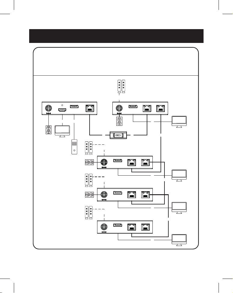
Receiver with Repeater Daisy-Chain Installation
Model B127A-111-BTBD and B127A-110-BD
Notes:
1) Test to ensure the entire installation works properly before pulling cables through
ceilings/walls
2) To achieve maximum distance and performance, use 24 AWG solid wire Cat6 cable.
Using stranded wire Cat6 cable or cable with a gauge (AWG) size higher than 24
AWG will result in shorter extension distance. Higher gauge cabling, such as 26
AWG, has a more limited transmission capability than lower gauge cabling. N202-
Series Cat6 cables are made with 24 AWG solid wire cabling.
3) The installation diagram shows the B127A-111-BDTD and B127A-110-BD
installation.
4) The B127A-111-BDTD and B127A-110-BD can be daisy-chained up to 4 levels,
each link extending 230 ft. (70 m) for a total of 920 ft. (280 m). This distance can
be extended a total of 1,090 ft. (330 m) by adding a B127A-010-H signal booster
between the transmitter and rst receiver in the daisy-chain installation.
5) If there are issues with a ickering video signal after installation, remove the Cat6
cable and try another one, either the same length or shorter. If the icker persists,
change the host computer's resolution to 1920 x 1080 to see if the image itself is
stable.
Standard Extender Kit Installation
10. The (orange) RJ45 LED will illuminate on both the local transmitter
and remote receiver units to indicate a signal is being received
from the source to display. The screen should now display on the
connected monitor.
15
Receiver with Repeater Daisy-Chain Installation
Level 4
Level 3
Level 2
Level 1
DC 24V, 1A
OUTPUTOUTPUT
INPUT
DC 24V, 1A
OUTPUTOUTPUT
INPUT
DC 24V, 1A
OUTPUTOUTPUT
INPUT
DC 24V, 1A
OUTPUTOUTPUT
INPUT
DC 24V, 1A
OUTPUTOUTPUT
INPUT
Up to 230 ft. (70 m) Cat6 cable at 4K/60Hz
Up to 15 ft. (4.5 m) HDMI 2.0 cable at 4K/60Hz
Toslink cable
Up to 200 ft. (60.9 m) Cat6 solid cable at 4K/60Hz
Up to 15 ft. (4.5 m) DisplayPort cable at 4K/60Hz
DC 24V, 1A
OUTPUTLOCAL INPUT
B127A-110-BD
extender kit
DisplayPort
Source
Monitor
Monitor
Monitor
Monitor
Monitor
B127A-110-BD
extender kit
Up to 230 ft. (70 m) Cat6 solid cable at 4K/60 Hz
Up to 15 ft. (4.5 m) HDMI 2.0 cable at 4K/60 Hz
Toslink cable
Up to 200 ft. (60.9 m) Cat6 solid cable at 4K/60 Hz
Up to 15 ft. (4.5 m) DisplayPort cable at 4K/60 Hz
Monitor
Monitor
Monitor
Monitor
Monitor
DisplayPort
Source
Level 1
Level 2
Level 3
Level 4

16
1. Make sure all equipment in the installation – such as TVs, Blu-ray
players and the transmitter – is powered OFF.
2. Connect the DisplayPort source to the INPUT port on the
B127A-111-BDTD local transmitter unit using a DisplayPort cable
(such as P580-Series cables).
3. Connect a local monitor to the local HDMI port using an HDMI cable
(such as P569-XXX-CERT or P568-XXX-2A High-Speed HDMI cables)
4. Optional: To increase the maximum transmission distance, connect
a B127A-010-H signal booster (sold separately) between the
transmitter and receiver using Cat6 cable.
Note: In a daisy-chain installation, the B127A-010-H signal booster unit must be
placed between the transmitter and first receiver in the chain or the signal booster
will not function.
5. Using Cat6 cable, connect one of the RJ45 output ports on the local
unit to the RJ45 input port on the B127A-111-BDTD transceiver unit.
6. Connect a monitor to the DisplayPort output port on the transceiver
unit using a DisplayPort cable (such as P580-Series DisplayPort
Cables).
7. Connect the external power supply to the local transmitter unit
and plug it into a surge protector, power distribution unit (PDU)
or uninterruptible power supply (UPS). The green RJ45 LED on
the receiver will illuminate to indicate the unit is receiving power.
Up to four units can be daisy-chained (one transmitter and three
transceivers). To connect additional transceiver units, proceed to
step 8. To finish your installation with a B127A-110-BD unit, proceed
to step 12.
8. Using Cat6 cable, connect the RJ45 output port on the
B127A-111-BDTD unit receiver unit to the RJ45 input port on a
B127A-110-BD transceiver unit.
Receiver with Repeater Daisy-Chain Installation

17
Receiver with Repeater Daisy-Chain Installation
9. Connect a monitor to the DisplayPort output port on the
B127A-110-BD that you just added using a DisplayPort cable (such as
P580-Series DisplayPort cables).
10. Connect the external power supply to the B127A-110-BD and
plug it into a surge protector, power distribution unit (PDU or
uninterruptible power supply (UPS). The green power LED and
the green RJ45 LED’s will illuminate to indicate the unit is receiving
power.
11. To add a second B127A-110-BH, repeat steps 8 through 10. To
finish your installation with a B127A-110-BH, proceed to step 12.
12. Using Cat6 cable, connect the RJ45 OUTPUT port on the last
B127A-110-BD to the RJ45 INPUT port.
13. Connect a monitor to the DisplayPort INPUT port on the last
B127A-110-BD using a DisplayPort cable.
14. The green LED on the B127A-110-BD will illuminate to indicate the
unit is receiving power from the previous transceiver. The orange
LED will illuminate to indicate the unit is connected to a powered
ON remote/repeater unit.
15. Turn on the power to the DisplayPort source. The orange RJ45 LED’s
on the local unit will illuminate to indicate a signal is being received
from the source.
16. The maximum number of daisy-chain layers is four for a total
distance of 920 ft., but the distance can be extended to 1,090 ft.
when a B127A-010-H signal booster is used. See the B127A-010-H
product features on Tripplite.Eaton.com for details.

18
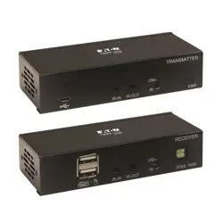
USB/IR Controls
(B127A-1A1-BDBD and B127A-1A1-BDBH only)
The B127A-1A1-BDBD and B127A-1A1-BDBH extender kits provide the
following functional controls:
• USB 1.1 – One USB Micro-B input at transmitter, dual USB-A outputs
at receiver
• Bi-Directional IR – Dual 3.5 mm jacks at both the transmitter and
receiver
(Optional) Connect the included IR-OUT cable to the transmitter unit’s
IR-OUT port. Place the sensor on the IR-OUT cable in an unobstructed
area within clear view of the device being controlled. Then connect the
included IR-IN cable to the receiver unit’s IR-IN port. The IR-IN cable will
communicate the desired command via the transmitter’s IR-OUT cable.
Note: The IR-OUT cable receives the signal from the remote control and sends it to the
device being controlled (e.g. Blu-ray player, etc.).
(Optional) With a user-supplied USB Micro-B cable (such as
U050-XXX Series USB cable), connect to the transmitter’s Micro-B port.
Then connect a keyboard and mouse to the available USB-A ports on the
receiver unit.
19
Warranty
1-Year Limited Warranty
We warrant our products to be free from defects in materials and workmanship for a period of
one (1) year from the date of initial purchase. Our obligation under this warranty is limited to
repairing or replacing (at its sole option) any such defective products. Visit Tripplite.Eaton.com/
support/product-returns before sending any equipment back for repair. This warranty does not
apply to equipment which has been damaged by accident, negligence or misapplication or has
been altered or modied in any way.
EXCEPT AS PROVIDED HEREIN, WE MAKE NO WARRANTIES, EXPRESS OR IMPLIED, INCLUDING
WARRANTIES OF MERCHANTABILITY AND FITNESS FOR A PARTICULAR PURPOSE. Some states do
not permit limitation or exclusion of implied warranties; therefore, the aforesaid limitation(s) or
exclusion(s) may not apply to the purchaser.
EXCEPT AS PROVIDED ABOVE, IN NO EVENT WILL WE BE LIABLE FOR DIRECT, INDIRECT, SPECIAL,
INCIDENTAL OR CONSEQUENTIAL DAMAGES ARISING OUT OF THE USE OF THIS PRODUCT, EVEN
IF ADVISED OF THE POSSIBILITY OF SUCH DAMAGE. Specically, we are not liable for any costs,
such as lost prots or revenue, loss of equipment, loss of use of equipment, loss of software, loss
of data, costs of substitutes, claims by third parties, or otherwise.
WEEE Compliance Information for Customers and Recyclers (European
Union)
Under the Waste Electrical and Electronic Equipment (WEEE) Directive and implementing
regulations, when customers buy new electrical and electronic equipment from Eaton,
they are entitled to:
• Send old equipment for recycling on a one-for-one, like-for-like basis (this varies
depending on the country)
• Send the new equipment back for recycling when this ultimately becomes waste
WARNING
Use of this equipment in life support applications where failure of this equipment can reasonably
be expected to cause the failure of the life support equipment or to signicantly aect its safety
or eectiveness is not recommended.
Eaton has a policy of continuous improvement. Specications are subject to change without
notice. Photos and illustrations may dier slightly from actual products.

20
Eaton
1000 Eaton Boulevard
Cleveland, OH 44122
United States
Eaton.com
© 2023 Eaton
All Rights Reserved
Publication No. 23-09-157 /
93-3D25_RevE
September 2023
Eaton is a registered
trademark.
All trademarks are property
of their respective owners.
933D25