MAC Viper XIP
User Manual
with Safety and Installation Manual

User documentation update information
Revision E
Added Stand-Alone mode, additional outdoor actions, fixture-to-fixture firmware upload, support for multi-universe
overflow. Very slight increase in zoom angle at wide end of zoom range. Non-resettable counters GET command
available via RDM. Several improvements for clarity.
Covers fixture firmware v. 1.2.x.
Revision D
Added FX macros, Framing Mode, rain sensor and outdoor use functions, service log, NFC functionality, control data
source and power supply readouts, and information on storing the battery cover in the head air filter compartment when
using a wireless Universal Connect Module. Added ‘Wet locations’ classification.
Covers fixture firmware v. 1.1.0.
Revision C
Added error message SRNM / SR NO MISMATCH. Added warning about opening fixture for service in dry conditions
only.
Covers fixture firmware v. 1.0.0.
Revision B
First public release.
Covers fixture firmware v. 1.0.0.
©2024–2025 HARMAN PROFESSIONAL DENMARK ApS. All rights reserved. Features, specifications and appearance are subject to
change without notice. HARMAN PROFESSIONAL DENMARK ApS and all affiliated companies disclaim liability for any injury, damage,
direct or indirect loss, consequential or economic loss or any other loss occasioned by the use of, inability to use or reliance on the
information contained in this document. Martin is a registered trademark of HARMAN PROFESSIONAL DENMARK ApS registered in
the United States and/or other countries.
HARMAN PROFESSIONAL DENMARK ApS, Olof Palmes Allé 44, 8200 Aarhus N, Denmark
HARMAN PROFESSIONAL, INC. 8500 Balboa Blvd., Northridge CA 91325, USA
www.martin.com
MAC Viper XIP User Manual with Safety and Installation Manual, English, P/N 5145649-00, Revision E

Table of contents
Introduction ......................................................................................... 5
Operating the fixture ................................................................. 5
Applying mains power .............................................................. 6
Cold starting ............................................................................. 6
Connecting to data ............................................................................. 6
Data via DMX cable ................................................................. 6
Data via Ethernet cable ............................................................ 7
Control options ................................................................................... 9
DMX ......................................................................................... 9
P3 creative LED and video....................................................... 9
RDM ....................................................................................... 10
Effects ............................................................................................... 11
Rotating gobos ....................................................................... 11
Animation wheel ..................................................................... 14
Light and heavy frost .............................................................. 14
Rotating prism ........................................................................ 14
Iris ........................................................................................... 14
Zoom ...................................................................................... 14
Framing .................................................................................. 15
Zoom and focus ..................................................................... 15
FX: Pre-programmed effects macros ..................................... 16
LED frequency ....................................................................... 16
Pan and Tilt ............................................................................ 16
Fixture setup ..................................................................................... 17
Fixture ID ................................................................................ 17
DMX control mode ................................................................. 17
DMX address ......................................................................... 17
DMX universe ......................................................................... 17
Network settings ..................................................................... 17
Pan/tilt inversion ..................................................................... 18
Pan/tilt speed ......................................................................... 18
Effects speed ......................................................................... 18
Pan and tilt limits .................................................................... 18
Pan and tilt feedback .............................................................. 19
Followspot mode .................................................................... 19
Dimming curves ..................................................................... 20
Tungsten emulation ................................................................ 20
Gobo CT correction ................................................................ 20
Keylight calibration ................................................................. 20
Color mode ............................................................................. 21
Focus tracking ........................................................................ 21
Video tracking ........................................................................ 21
Cooling mode ......................................................................... 21
Studio mode ........................................................................... 22
Outdoor operation and drying out function ............................. 22
DMX reset enable .................................................................. 23
Effect shortcuts ...................................................................... 23
Display on/off ......................................................................... 23
Display sleep .......................................................................... 23
Display rotation ...................................................................... 23
Display intensity ..................................................................... 23
Display contrast ...................................................................... 24

Error display mode ................................................................. 24
Hibernation mode ................................................................... 24
Framing mode ........................................................................ 24
Stand-alone operation ............................................................ 24
Storing and recalling custom settings .................................... 26
Resetting to factory defaults................................................... 26
Fixture information readouts .................................................. 26
Fan cleaning ........................................................................... 28
DMX LIVE signal monitoring .................................................. 28
Manual control ........................................................................ 28
Viewing stored status messages ........................................... 28
Fixture test sequences ........................................................... 29
Resetting the fixture ............................................................... 29
Calibration .............................................................................. 29
Adjustment menu (Martin Global Service only) ...................... 30
Loading factory default calibration values .............................. 31
Displaying test patterns .......................................................... 31
‘Identify device’ signal ............................................................ 31
Service log.............................................................................. 31
Control panel .................................................................................... 32
Using the control panel .......................................................... 32
Status LED ............................................................................. 32
Battery power ......................................................................... 33
Shortcuts ................................................................................ 33
Settings stored permanently .................................................. 33
Activating service mode ......................................................... 34
Using RDM ....................................................................................... 35
Martin Companion
®
and RDM ................................................ 35
RDM functions ........................................................................ 36
Using NFC ........................................................................................ 40
Control menus .................................................................................. 41
DMX protocols .................................................................................. 49
Basic DMX Mode ................................................................... 49
Extended DMX Mode ............................................................. 55
Ludicrous DMX Mode ............................................................. 61
Control/Settings DMX channel ......................................................... 62
FX ..................................................................................................... 65
FX table .................................................................................. 66
Pan/tilt and zoom orientation guide .................................................. 70
Service messages ............................................................................ 72
Accessories and service procedures................................................ 78
Uploading new firmware ......................................................... 78
Fixture-to-fixture firmware uploads ........................................ 79
Installing a Universal Connect Module ................................... 80
Installing a Hexcel Louver ...................................................... 81
Installing a Concentric Ring louver ........................................ 82
Installing a Followspot Handle ............................................... 82
Removing the top head cover ................................................ 83
Reinstalling the head cover .................................................... 84
Internal effect module calibration ........................................... 85
Replacing rotating gobos ....................................................... 85

Martin
®
MAC Viper XIP User Manual Revision E 5
Introduction
Warning! Before installing, operating or servicing the MAC Viper XIP lighting
fixture, read the latest version of the fixture’s Safety and Installation Manual,
paying particular attention to the Safety Precautions section. The Safety and
Installation Manual is supplied with the fixture and included at the back of this
user manual. The latest version is also available for download from the MAC
Viper XIP area of the Martin® website at www.martin.com.
Important! Full specifications for MAC Viper XIP fixtures and accessories are
available in the MAC Viper XIP area of the Martin
®
website at www.martin.com.
Thank you for selecting the MAC Viper XIP lighting fixture from Martin.
This User Manual is a supplement to the Safety and Installation Manual that is supplied with the fixture
and attached to the back of this User Manual. The User Manual contains information that is mainly of
interest for lighting designers and operators, whereas the Safety and Installation Manual contains
important information for all users, especially installers and technicians.
We recommend that you check the Martin website regularly for updated documentation. We publish
revised versions each time we can improve the quality of the information we provide and each time we
release new firmware with changes or new features. Each time we revise this guide we list any
important changes on page 2 so that you can keep track of updates.
The output of LEDs, like all light sources, changes gradually over many thousands of hours of use. If
you require products to perform to very precise color specifications, you may eventually need to make
small readjustments at the lighting controller.
Operating the fixture
Before applying power to or operating the MAC Viper XIP:
• Read the ‘Safety Information’ section of the fixture’s Safety and Installation Manual that is included
at the end of this User Guide, supplied with the fixture and available for download from the Martin
website at www.martin.com.
• Check that the installation is safe and secure.
• If the fixture is moved from a cold to a warm environment, remove it from its flightcase or
packaging and give it at least two hours to acclimatize before applying power. This will help to
avoid damage due to condensation.
• Check that the fixture is in perfect condition. Do not apply power to a fixture that is obviously
damaged, or you may create a safety risk and make the damage worse.
• Check that the base is fastened securely so that the torque reaction when the head moves will not
cause the base to move.
• Check that the head tilt lock is released.
• Be prepared for the head to move suddenly. Check that there will be no risk of collision with
persons or objects.
• Be prepared for the fixture to light up suddenly. Check that no-one is looking at the fixture from
close range.
• Check that the voltage and frequency of the power supply match the power requirements of the
fixture.

6 Martin
®
MAC Viper XIP User Manual Revision E
Applying mains power
The fixture does not have an on/off switch. It becomes active as soon as AC mains power is applied at
the power input connector. Be prepared for the head to move and for the fixture to suddenly emit bright
light.
Each time power is applied to the fixture, it will reset all effects and functions to their home positions. A
reset typically takes around 45 seconds.
Cold starting
At +5° C (41° F) and below, the fixture starts up in cold-start mode. In this mode, the current to some
motors is increased and reset speed is reduced. This makes sure that the fixture can reset safely
without any step loss. After a successful reset, the fixture stays in cold-start mode until it has warmed
up. In cold-start mode there is a slight increase in noise from the fixture. Some effects (especially gobo
changes and speed) are slower than normal.
The fixture begins to exit cold-start mode when it reaches an internal temperature of approximately
15° C (59° F). By the time it reaches 20° C (68° F) it has exited cold-start mode completely.
To warm up the fixture as quickly as possible, set LED output to full intensity. If you prefer the fixture
not to project light during warmup, set the CMY and CTO flags to 99%, i.e. almost fully closed, and set
all framing blades to 99%, i.e. almost fully inserted. Note that if you set framing blades to 100% (fully
inserted), LED output will be shut down and the LED warmup effect will be lost.
Connecting to data
Warning! Before installing the MAC Viper XIP, read the latest version of the fixture’s Safety and
Installation Manual that is attached to the User Manual, paying particular attention to the ‘Safety
Precautions’ section. Besides important safety information, the Safety and Installation Manual contains
instructions for connecting to AC mains power.
When using the fixture outdoors or in any environment where water or humidity is present, use
connectors rated minimum IP65.
If independent control of a fixture is required, it must have its own DMX channels. Fixtures that are
required to behave identically can share the same DMX address and channels.
The number of fixtures that you can connect to DMX data in a daisy chain is limited by the number of
DMX channels required by the fixtures. A maximum of 512 channels is available in one DMX universe.
To add more fixtures or groups of fixtures when you no longer have enough DMX channels, add a
DMX universe and another daisy-chained link.
The MAC Viper XIP has two pairs of connectors for control data In/Out:
• one pair of locking 5-pin XLR sockets that accept IP65-rated Neutrik TOP (or compatible)
connectors, and
• one pair of etherCON sockets that accept IP65-rated Neutrik TOP (or compatible) Ethernet
connectors.
All sockets are protected by rubber caps. Keep the rubber caps in place at all times on unused sockets.
Data via DMX cable
The MAC Viper XIP has 5-pin locking XLR sockets for DMX and RDM input and output via DMX cable.
The pin-out on both sockets is:
• Pin 1 to shield
• Pin 2 to data 1 cold (-)
• Pin 3 to data 1 hot (+).
Pins 4 and 5 are not used by the fixture but are bridged between input and output sockets. These pins
can therefore be used as a pass-through connection for an additional data signal if required.

Martin
®
MAC Viper XIP User Manual Revision E 7
Tips for reliable data transmission via DMX cable
• Use shielded twisted-pair high-quality DMX cable.
• 24 AWG cable is suitable for runs up to 300 meters (1000 ft). Heavier gauge cable and/or an
amplifier is recommended for longer runs.
• Do not use microphone cable, as standard microphone cable does not have the correct impedance
and cannot transmit control data reliably over long runs.
• To split the data link into branches, use an optically isolated splitter-amplifier. Use an RDM-
compatible splitter-amplifier when using RDM.
• Do not overload the DMX data link. You can connect up to a maximum of 32 devices on a serial
DMX link.
• Install a DMX termination plug at the end of the DMX link.
Connecting to data via DMX cable
To connect the fixture to DMX and/or RDM data carried over DMX cable:
1. Connect the DMX data output from the controller to the fixture’s data input (male XLR) socket
using good-quality DMX cable.
2. Run DMX cable from the fixture’s data output (female XLR) socket to the data input of the next
fixture and continue until the link is complete.
3. Terminate the data link by connecting a 120 Ohm, 0.25 Watt resistor between the data 1 hot (+)
and cold (-) conductors at the end of the link. If the link is divided into branches using a DMX
splitter, terminate each branch of the link.
Data via Ethernet cable
The MAC Viper XIP has etherCON data sockets that support Art-Net, sACN and Martin P3. Either
socket can be used for input and the other socket used for throughput. The etherCON data sockets
have a fail-safe bypass feature. This means that the fixture will relay a data signal from the socket used
for input to the socket used for throughput even if power to the fixture is shut down or lost.
Tips for reliable data transmission via Ethernet cable
• Use shielded twisted-pair Ethernet cable of type S/UTP, SF/UTP, S/STP or SF/STP only. The
cable must be rated Cat 5e or better.
• The cable shield must be electrically connected to connector housings, and the other devices on
the data link must also support shielded connections.
• The MAC Viper XIP is compatible with 10/100 Mbit Ethernet only. Do not connect the fixture to a
network port or device that is fixed to Gigabit Ethernet speed. If you need to integrate an MAC
Viper XIP in a Gigabit Ethernet network, use a network switch to allow the link towards the fixture
to operate at 100 Mbit/s Ethernet speed.
• To split the data link into branches, use a standard network switch that is able to operate at 100
Mbit/s towards the fixtures.
• Even though every fixture has a fail-safe bypass mechanism and minimal latency insertion, we
recommend that you avoid connecting more than 50 devices in a single daisy-chain or branch.
• Unlike DMX cable, Ethernet cable does not require termination at the end of a daisy-chain of
fixtures.
Connecting to data via Ethernet cable
To connect the fixture to Art-Net, sACN or Martin P3 via Ethernet cable:
1. Connect the Ethernet cable to either of the fixture’s etherCON data sockets.
2. Run Ethernet cable from the fixture’s other etherCON data socket to a data socket on the next
fixture.

8 Martin
®
MAC Viper XIP User Manual Revision E
3. Continue connecting data sockets as described above until the link is complete.
Fail-safe connection
The fixture has a fail-safe network connection. If the fixture loses power or if you shut it down, it will
continue to relay an Ethernet signal – the Art-Net / sACN / P3 signal to the other networked fixtures in
the daisy chain will not be interrupted.
Data rate
Any Ethernet switch used to relay Art-Net, sACN or P3 data to the fixture must be capable of running at
10/100 Mbps speed, as the fixture does not support Gigabit Ethernet data rates.

Martin
®
MAC Viper XIP User Manual Revision E 9
Control options
You can control the MAC Viper XIP using DMX and/or Martin P3 protocol, and the fixture is also RDM-
compatible. The fixture auto-senses the type of data that it is receiving and will respond correctly with
no need for manual protocol selection.
The following options are available:
• DMX control over standard DMX cable connected to the fixture’s 5-pin XLR connectors.
• DMX control using Art-Net over Ethernet cable connected to the fixture’s etherCON connectors.
• DMX control using streaming ACN over Ethernet cable connected to the fixture’s etherCON
connectors.
• DMX control over DMX cable and P3 video data over Ethernet cable.
• P3 video data with embedded DMX commands over Ethernet cable. If you connect DMX / Art-Net /
sACN to the P3 system controller, the controller can merge the DMX commands into the P3 signal
and send them to the fixture over Ethernet.
The P3 Mix DMX channel lets you choose how the fixture should behave if it receives both DMX data
and P3 video data. You can use the P3 video pixel data to control the intensity and/or the color of the
fixture’s output with real-time control.
UCM accessory
The fixture’s UCM (Universal Connect Module) port lets you connect a wireless control receiver
(available from different manufacturers).
Data rate
Any Ethernet switch used to relay Art-Net, streaming ACN or P3 data to the MAC Viper XIP must be
capable of running at 10/100 Mbps speed, as the fixture does not support Gigabit Ethernet data rates.
DMX
The MAC Viper XIP accepts a DMX-512A data signal.
DMX setup
The DMX address, also known as the start channel, is the first channel used to receive instructions
from the controller. For independent control, each fixture must be assigned its own control channels. If
you give the same DMX address to two fixtures of the same type, they will behave identically. Address
sharing can be useful for diagnostic purposes and symmetrical control, particularly when combined
with the inverse pan and tilt options.
From firmware v. 1.2.x the fixture supports multi-universe overflow. If a fixture’s DMX footprint exceeds
the number of control channels available for the fixture in one DMX universe, the fixture automatically
uses channels at the start of the next DMX universe.
DMX modes
You can set the MAC Viper XIP to one of three DMX operating modes: Basic, Extended and Ludicrous
See the DMX Protocols section starting on page 49 of this manual for details of the commands
available and number of DMX channels used in each DMX mode.
P3 creative LED and video
The MAC Viper XIP accepts video data using Martin’s proprietary P3 video protocol that has been a
well-established standard in the industry for over 15 years. It lets you send a video signal from a media
server or other video source to P3-compliant creative LED fixtures and moving heads over Ethernet
cable using Martin’s reliable P3 data protocol.

10 Martin
®
MAC Viper XIP User Manual Revision E
The intuitive graphic user interface in Martin P3 controllers lets you visualize and set up a custom
installation that can contain a huge number of fixtures in any kind of physical arrangement within a few
minutes. Device identification is automatic. You can arrange devices on the monitor using drag-and-
drop. Latency from video input to output on fixtures is extremely low, while there is no latency between
fixtures as they are fully synchronized via the P3 protocol. If you use P3 you do not need to worry
about IP addresses, as P3 does not use IP addresses or IP communication.
The P3 protocol will supply both DMX data and video pixel data to fixtures over a network cable. On
the MAC Viper XIP you can use the video pixel data to control the intensity and/or the color of the
fixture’s output with real-time control using the P3 Mix DMX channel.
RDM
The MAC Viper XIP is compatible with RDM (Remote Device Management), which allows remote
fixture setup and management over the DMX data link. See ‘Using RDM’ on page 35.
Martin
®
MAC Viper XIP User Manual Revision E 11
Effects
This section gives details of the effects available in the MAC Viper XIP. See the ‘DMX protocols’
section starting on page 49 for a full list of the DMX channels and values required to control the
different effects.
Shutter and strobe effects
The fixture’s electronic shutter effect provides instant blackout and snap open as well as regular or
random strobe effects with variable speed from approximately 1 Hz to 20 Hz.
Dimming
Smooth 0-100% overall dimming is available with 16-bit control resolution. Four dimming curves are
available (see ‘Dimming curves’ on page 20).
When Hybrid LED Dimming Mode is selected on channel 48 in Basic DMX Mode or channel 58 in
Extended and Ludicrous DMX Modes, dimming is achieved using reduction in electrical current from
100% to 70% intensity, and dimming is achieved using PWM from 70% to 0% intensity.
CMY color mixing
The fixture features CMY color mixing with 16-bit resolution. Colors are obtained using continuously
variable dichroic color flags with the following color characteristics:
• Cyan 529Y SP
• Magenta 606Y SP
• Yellow 519Y SP
• CTO 5800-3000Y SP
You may find it advantageous to deploy the Spectral Enhancement filter on the color wheel (see below)
in combination with CMY color mixing.
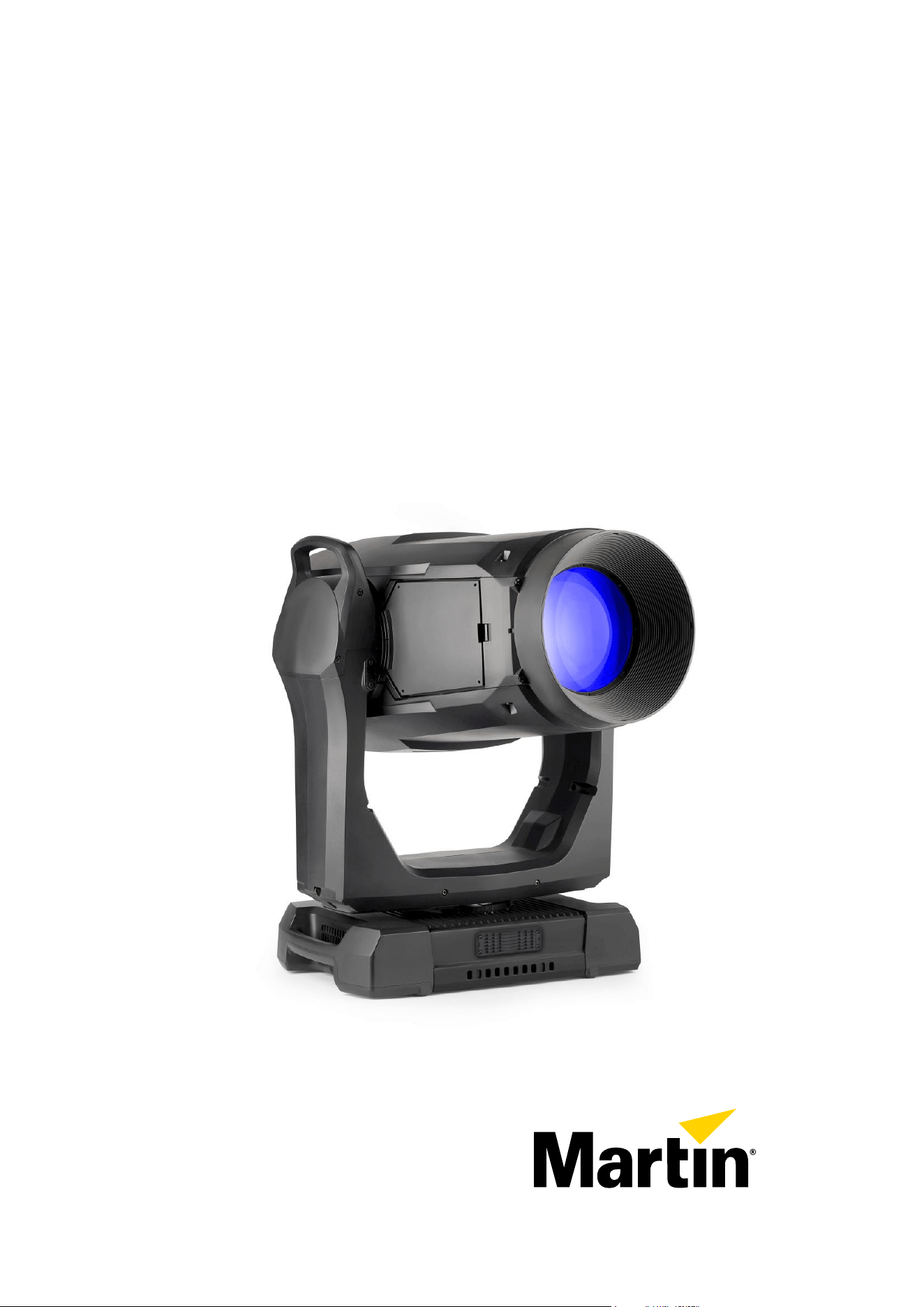
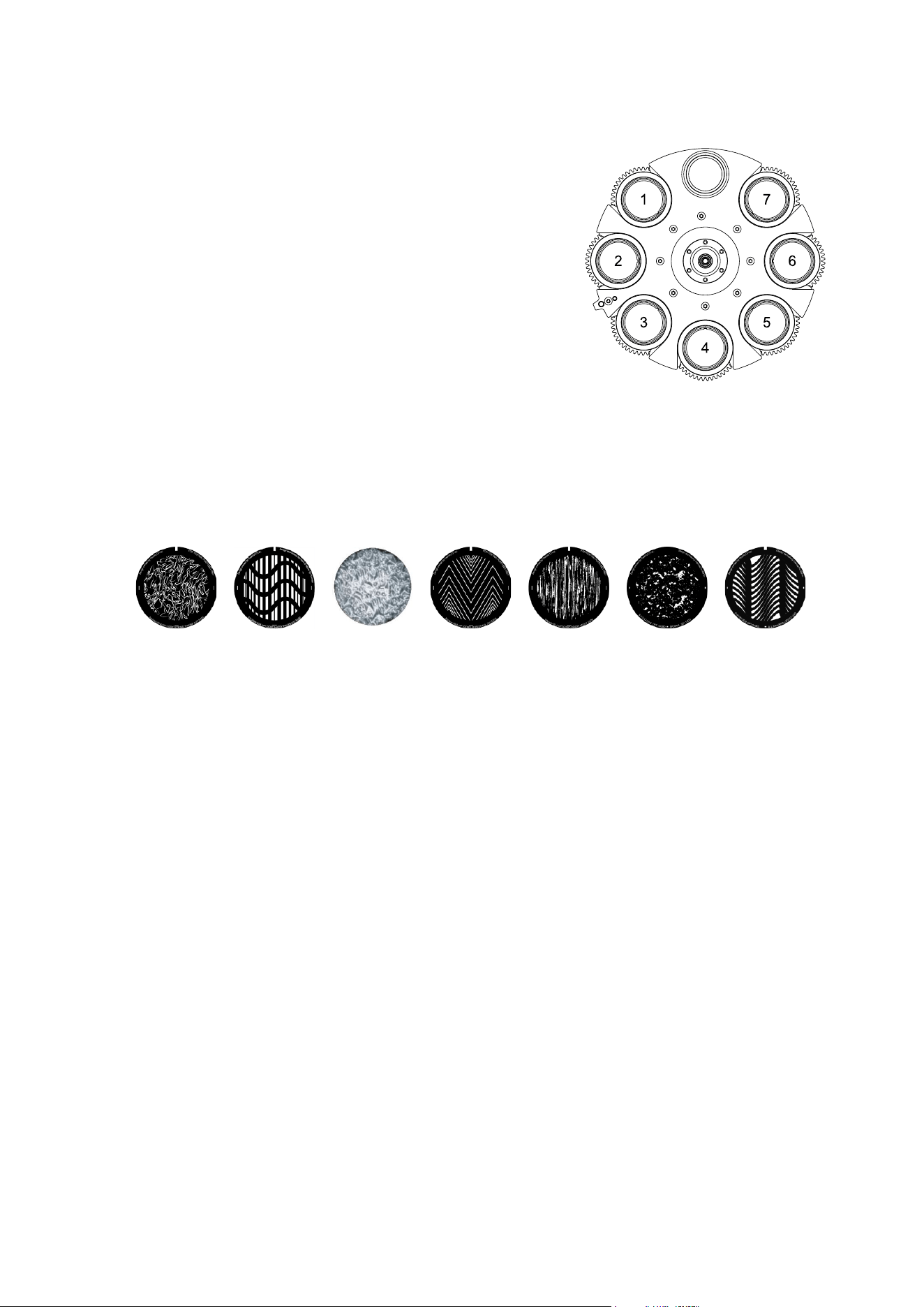
Color wheel
See illustration on right. The fixture features
a color wheel with five dichroic color filters
plus open. Besides stepped color selection
and variable wheel indexing, the color wheel
also offers continuous scrolling with variable
speed and direction, random colors and
color shake.
You can use CMY color mixing in
combination with the color wheel if you want
to fine-tune a color.
You may find it advantageous to deploy the
Spectral Enhancement filter in combination
with CMY color mixing.
Rotating gobos
The gobos on Gobo Wheel 1 and 2 in the MAC Viper XIP have the same dimensions and
specifications and are therefore interchangeable, but the goboholders on the two gobo wheels are
different. You cannot move a goboholder from one gobo wheel to the other.
We number gobo wheels in Martin fixtures starting from the light source. In the MAC Viper XIP:
• The wheel closer to the LEDs is Gobo Wheel 1, the aerial effects wheel.
• The wheel closer to the front lens is Gobo Wheel 2, the breakup effects wheel.
5
Dark Red
630Y SP
2
CTB
CTB67b SP
3
Orange
593Y SP
1
Spectral
Enhancement
CRI 447 SP
4
Navy Blue
444Y SP
12 Martin
®
MAC Viper XIP User Manual Revision E
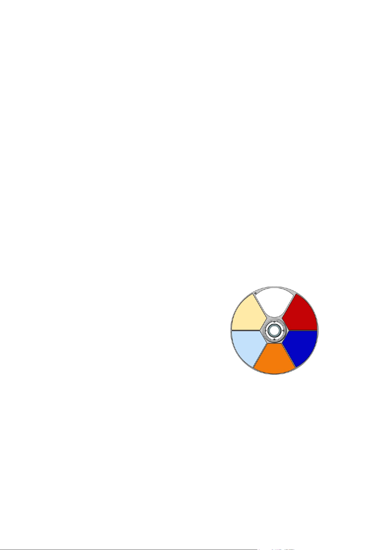
Gobo Wheel 1 – aerial wheel
Gobo Wheel 1, the aerial effects wheel, has seven rotating
gobos that can be used in any situation but are especially
suitable for midair effects. Gobos can be selected, indexed
(positioned at an angle), rotated continuously and shaken
(bounced).
Gobo selection on Gobo Wheel 1 is done on channel 15 in all
the fixture’s DMX modes. This channel offers gobo selection,
gobo shake, continuous gobo wheel rotation and random gobo
selection.
The following two channels (channel 16 and 17) set gobo
indexing or gobo continuous rotation with 16-bit control
resolution. Both functions can be combined with any selection
on channel 15. Making a change on channel 15 will not change
the behavior selected on channels 16 and 17.
All gobos are interchangeable. Details of gobo replacement
procedures are given towards the end of this manual.
The slots on the rotating gobo wheel are ordered as shown on the right.
The fixture’s standard gobos are shown in the correct order below.
1
2
3
4
5
6
7
Slot
Gobo
P/N
1
Time Ripples
P/N: 5141771-00
2
Look Sharper
P/N: 5141772-00
3
Compass
P/N: 5141773-00
4
Deep Space
P/N: 5141774-00
5
Radar
P/N: 5141775-00
6
Short Cuts
P/N: 5141776-00
7
A Lot of Spot
P/N: 5141777-00
MAC Viper XIP Gobo Wheel 1
Gobo Wheel 1
(seen from LED side)
Martin
®
MAC Viper XIP User Manual Revision E 13
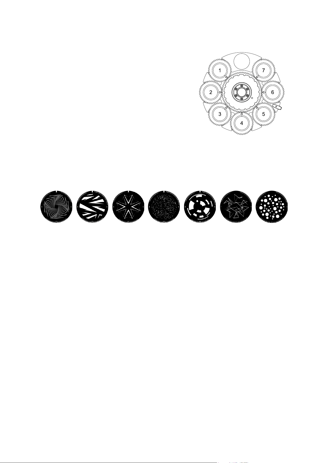
Gobo Wheel 2 - breakup wheel
Gobo Wheel 2, the breakup effects wheel, has seven rotating
gobos that can be used in any situation but are especially
suitable for breakup effects when used together with the
animation wheel.
Gobo selection on Gobo Wheel 2 is done on channel 18 in all
the fixture’s DMX modes. This channel offers gobo selection,
gobo shake, continuous gobo wheel rotation and random gobo
selection.
The following two channels (channel 19 and 20) set gobo
indexing or gobo continuous rotation with 16-bit control
resolution. Both functions can be combined with any selection
on channel 18. Making a change on channel 18 will not change
the behavior selected on channels 19 and 20.
All gobos are interchangeable except Gobo 3 (Limbo), which is
fused glass and is glued into the goboholder. Details of gobo
replacement procedures are given towards the end of this
manual.
The slots on the rotating gobo wheel are ordered as shown on the right. The fixture’s standard gobos
are shown in the correct order below.
1
2
3
4
5
6
7
Slot
Gobo
P/N
1
String Theory
P/N: 5141778-00
2
Hazey Waves
P/N: 5141779-00
3
Limbo
P/N: 5141840-00
4
Up Is Down
P/N: 5141780-00
5
Brush Up
P/N: 5141781-00
6
Sponge
P/N: 5141782-00
7
All Wrapped Up
P/N: 5141783-00
MAC Viper XIP Gobo Wheel 2
Gobo Wheel 2
(seen from LED side)

14 Martin
®
MAC Viper XIP User Manual Revision E
Animation wheel
The MAC Viper XIP is supplied with the “Worms That
Turn” gobo animation wheel (P/N: 5139137-00)
installed. The wheel can be used to add animation
effects to gobo projections. When using gobo
animation, adjusting the fixture’s focus will help obtain
the most realistic results.
You can insert the animation wheel into the beam or
select a gentle animation wheel shake (a gentle
rocking movement) with variable speed on channel 21
in all the fixture’s DMX Modes. Once you have
deployed the animation wheel on channel 21, you can
select a static indexed angle, continuous animation
wheel rotation or define the center angle for the
animation wheel gentle shake with 16-bit resolution on
channels 22 and 23 in all DMX Modes.
Light and heavy frost
The MAC Viper XIP features two frost filters that are controllable via DMX: a light and a heavy filter.
The light frost filter – Frost filter 1 - is mounted in the same plane as the prism inside the fixture, so you
cannot use these two effects at the same time. If you try to deploy both effects at the same time, the
prism takes priority. Deploying the light frost filter slightly limits the narrowest zoom angle available.
The heavy frost filter – Frost filter 2 – can be deployed at all times. Deploying the heavy frost filter
slightly limits the narrowest zoom angle available.
Rotating prism
The MAC Viper XIP features a four-facet circular prism for multiple beam effects. The prism can be
inserted into the beam at indexed angles, rotated with variable direction and speed or shaken with
variable speed.
Inserting the prism slightly limits the narrowest zoom angle available.
Iris
The fixture has a motorized iris that can be set to a static aperture to narrow the beam. You can also
set the iris to a dynamic opening or closing pulse with variable speed.
Zoom
Zoom control via DMX lets you vary the beam angle within this range:
• Wide
- Beam angle (half-peak): 51.9°
- Field angle (tenth-peak): 53.6°
- Cutoff angle (3%): 53.9°
• Narrow
- Beam angle (half-peak): 5.1°
- Field angle (tenth-peak): 5.7°
- Cutoff angle (3%): 5.9°
‘Worms That Turn’ gobo
animation wheel

Martin
®
MAC Viper XIP User Manual Revision E 15
Framing
The MAC Viper XIP’s framing module has 4 individually controllable framing blades with fully variable
angle of +/-30° through the entire insertion path from 0-100% (full curtain). The whole framing module
can rotate through +/-83°.
The framing blades have independent control of angle and amount of insertion for each blade.
Adjusting these parameters gives enormous flexibility in forming the beam into shapes of different sizes
with three or four sides. It is possible to angle the framing blades before inserting them into the beam –
a feature that gives more creative possibilities.
With the fixture installed in a lighting rig with the head below the base and with the head the right way
up, the framing blades are numbered counting clockwise from the 12 o’clock position:
• Blade 1 = Top
• Blade 2 = Right
• Blade 3 = Bottom
• Blade 4 = Left
16-bit control of framing blade position and angle and 16-bit control of framing module angle are
available in Extended DMX Mode.
Two framing control modes are available from firmware v.1.1.0 (see ‘Framing mode’ on page 24).
Zoom and focus
Adjusting focus lets you vary the sharpness of projected images at different distances. It can be
particularly effective when used together with gobos and the animation wheel.
The MAC Viper XIP’s zoom lens varies the focused field angle from 5.7° to 51°. Wide zoom angles
allow sharp focus on projection surfaces close to the fixture. At narrower zoom angles, sharp focus is
only possible further from the fixture.
If zoom is set to the narrowest position, it is not possible to focus on all effects at all distances. So
when Zoom/Focus tracking is disabled:
• You can find the narrowest zoom angle at which sharp focus is possible by setting focus to DMX
value = 0, then starting at the narrowest zoom angle and gradually moving towards wide until you
achieve sharp focus.
• At the widest zoom angle, simply set zoom to widest and adjust focus until you achieve sharp
focus.
When Zoom/Focus tracking is enabled, we suggest that you set zoom to medium and then change the
focus setting until you achieve sharp focus with the desired effect. Changing the zoom angle will now
automatically change focus to keep a relatively sharp focus (some fine tuning may be necessary if you
want the sharpest focus). Not all effects can be in sharp focus at all zoom settings. At some
combinations of effect and distance, zooming to the widest or narrowest angles can cause loss of focus
if the effect is no longer within its focusable zoom range at that distance.
Zoom/focus linking
Focus varies with zoom angle, but focus can be linked to zoom so that it automatically adjusts to match
changes in zoom angle. Focus on rotating gobos matches zoom closely, while focus on the animation
wheel matches zoom best in the center of the zoom range and slightly less precisely at the two
extremes of the zoom range.
Linked zoom/focus works within 3 distance ranges: close-, medium- and long-range. The ranges are as
follows (figures are approximate):
• Close (5 - 10 meters / 16.5 - 33 ft.)
• Medium (10 - 20 meters / 33 - 66 ft.)
• Long (20 meters - infinity / 66 ft. - ∞)

16 Martin
®
MAC Viper XIP User Manual Revision E
To link zoom and focus, select a distance range using the Control/Settings DMX channel, FOCUS
TRACKING in the control panel PERSONALITY menu, RDM or a P3 System Controller. Then adjust
focus to obtain the required degree of sharpness. Linking is now enabled and focus will auto-adjust to
match changes in zoom angle.
CTO
16-bit color temperature control using the CTO flag in the CMY module is available on two channels in
all the fixture’s DMX modes. You can adjust the fixture’s base color temperature from 5800 K to
2850 K.
CTC
8-bit color temperature control is available on a separate channel. You can adjust color temperature
from 2000 K to 12 850 K.
The default DMX value on this channel is 114. At this value, color temperature is not modified.
Changing the DMX value adjusts color temperature to a calibrated level on the black body curve. The
fixture achieves this by automatically deploying the CMY and CTO flags.
Green/Magenta shift
Green/Magenta shift, or tint, can be adjusted from a Magenta shift (0.05 negative Duv) to Green shift
(0.05 positive Duv).
The default DMX value on this channel is 127. At value 127-128, there is no green or magenta shift.
Changing the DMX value moves the white point off the black body curve towards green or magenta
while keeping the correlated color temperature unchanged. The fixture achieves this by automatically
deploying the CMY and CTO flags.
FX: Pre-programmed effects macros
FX are implemented from MAC Viper XIP firmware version 1.1.0. See ‘FX’ on page 65 for a full list of
the FX available.
You can quickly check which firmware version a fixture is running using the fixture’s control panel, an
RDM controller or a P3 system controller. For information on updating firmware, see ‘Uploading new
firmware’ on page 78.
LED frequency
In all DMX modes, it is possible to adjust the LED refresh rate by +/- 2% relative to the standard PWM
frequency of 2400 Hz.
The MAC Viper XIP features a Hybrid LED management setting that changes the LED dimming
functionality from pure PWM dimming to combined analog/PWM dimming. Hybrid LED dimming is
activated when the LED Frequency channel (48 in Basic Mode, 58 in Extended and Ludicrous Modes)
is set to zero. The hybrid LED dimming setting reduces dimming switching noise. Note that when
reducing light intensity using hybrid dimming, color temperature becomes warmer than when using
pure PWM dimming.
Pan and Tilt
The MAC Viper XIP ’s head can pan through a range of 540° and tilt through 268° with 16-bit control
resolution available in all the fixture’s DMX Modes.
See the pan/tilt orientation reference drawings at the end of this user manual for a guide to the
direction of pan and tilt movement.

Martin
®
MAC Viper XIP User Manual Revision E 17
Fixture setup
You can adjust fixture settings using one or more of the following methods:
• The fixture’s onboard control panel (see ‘Control panel’ on page 32)
• RDM (see ‘Using RDM’ on page 35)
• DMX (see ‘Control/Settings DMX channel’ on page 62)
• A Martin P3 System Controller
• NFC using the Martin Companion Mobile app (see ‘Using NFC’ on page 40).
Any changes that you make to the fixture’s settings are stored in memory when the fixture is powered
off.
Fixture ID
Available using: Control panel – RDM – P3 – NFC
FIXTURE ID lets you view or set a 4-digit custom ID number to help you identify the fixture. When you
open this setting for the first time, the fixture displays its DMX address. It will continue to display this
until you set an ID number for the fixture.
DMX control mode
Available using: Control panel – RDM – P3 – NFC
The MAC Viper XIP offers three DMX modes: Basic, Extended and Ludicrous. See the ‘DMX protocols’
section at the end of this manual for details of the DMX control options available in the different modes
and the number of DMX channels used.
Because the fixture’s DMX mode affects the number of DMX channels used, it will also affect the
assignment of DMX addresses to fixtures. It is therefore a good idea to set the DMX mode of all the
fixtures in the installation before you set their DMX addresses.
DMX address
Available using: Control panel – RDM – P3 – NFC
The DMX address, also known as the start channel, is the first channel used to receive instructions
from a DMX controller. If you have a group of fixtures and you set the first fixture’s DMX address to 1,
the fixture will use DMX channel 1 and the channels above it (the number of channels used will depend
on the fixture’s DMX mode). The channels above these are available for the next fixture.
For independent control, each fixture must be assigned its own control channels. You can give the
same DMX address to two fixtures of the same type if you want them to behave identically. Giving the
same DMX address to multiple fixtures can be useful for grouped control and troubleshooting.
DMX universe
Available using: Control panel – RDM – P3 – NFC
It is possible to manually set the fixture’s DMX universe from 1 to 63999.
From firmware v.1.2.x, fixtures that are connected via Art-Net, sACN or Martin P3 support multi-
universe overflow (channels can start in one DMX universe and continue into the next DMX universe).
Network settings
Available using: Control panel – RDM – P3 – NFC
The following Ethernet settings are available:
• IP ADDRESS lets you view the fixture’s IP address or manually set a new static IP address.
• SUBNET MASK lets you view the fixture’s subnet mask or manually set a new subnet mask.

18 Martin
®
MAC Viper XIP User Manual Revision E
• MAC ADDRESS lets you view the fixture’s 12-digit MAC address.
• RESET IP SETUP lets you clear all Ethernet settings and return the fixture to automatic
IP addressing, in which the fixture auto-generates its own IP address based on its MAC address.
Besides the above, RDM also offers additional advanced network settings (see ‘RDM functions’ on
page 36).
Pan/tilt inversion
Available using: Control panel – RDM – P3 – NFC
The PAN INVERT and TILT INVERT settings let you reverse the direction of pan and tilt. This can be
useful if you want to create symmetrical effects with multiple fixtures, or if you want to coordinate the
movement of fixtures that are standing on the floor with fixtures that are being flown upside down in a
rig.
Pan/tilt speed
Available using: Control panel – DMX – RDM – P3 – NFC
The PAN / TILT SPEED setting has three options:
• STANDARD is designed to give a good compromise between speed and smoothness of pan and
tilt movement.
• FAST optimizes pan and tilt movement for speed. Slow pan and tilt movement may be less
smooth.
• SMOOTH optimizes pan and tilt movement for smoothness. Maximum pan and tilt movement
speed is reduced.
Effects speed
Available using: Control panel – RDM – P3 – NFC
You can optimize effects movement depending on whether you want the fastest or the smoothest
action. There are four options:
• STANDARD is designed to give a good compromise between speed and smoothness of effects
movement.
• FAST optimizes effects movement for speed. Slow effects movement may be less smooth.
• SMOOTH optimizes effects movement for smoothness. Maximum effects movement speed is
reduced.
• FOLLOW P/T sets effects movement to the option that is selected for pan and tilt movement (see
above).
Pan and tilt limits
Available using: Control panel – DMX – RDM – P3 – NFC
The pan and tilt limit options let you define minimum and maximum limits for pan and tilt angles so that
you can install fixtures close to obstacles (such as other fixtures or trusses) with no risk of collision, so
that the beam will only hit a certain area of a stage or set, or so that you can avoid the fixture shining
into the eyes of the audience, for example. If you set limits, the fixture’s pan and tilt movement will
remain in a ‘safe zone’ within those limits.
The STORE LOWER PAN LIMIT and STORE UPPER PAN LIMIT settings define the minimum and
maximum limits for the fixture’s pan range. STORE LOWER TILT LIMIT and STORE UPPER TILT
LIMIT do the same thing for tilt range.
To set a limit, use the pan or tilt DMX channel to move the head to the position where you want to set
the limit, then send the relevant STORE command for the amount of time required to activate it.

Martin
®
MAC Viper XIP User Manual Revision E 19
Once you have stored one or more pan and tilt limits, send an ENABLE PAN AND TILT LIMITS
command to activate the limits. Sending a RESET PAN/TILT LIMITS command erases all the limits
that have been stored.
An LIM message appears in the control panel display when one or more pan and tilt limits are active.
Note that when you power the fixture off, the head may move under its own weight to a position that is
outside its pan and tilt limits.
Pan and tilt feedback
Available using: Control panel only
The fixture features pan/tilt position feedback sensors to ensure accurate positioning of the head.
Pan/tilt feedback is enabled by default. If you experience unexpected positioning behavior, it can be
useful to disable the pan/tilt position feedback system using the SERVICE control menu.
Pan and tilt feedback error timeouts
If the fixture cannot find a correct pan and/or tilt position, it tries to find the position for ten seconds.
• If within that ten-second period it finds the correct position and can hold it for two seconds, it drops
the ten-second period and returns to normal operation.
• If within that ten-second period it cannot find the correct position, it registers a pan/tilt feedback
error, shuts down light output and stops responding to pan and tilt control input. This minimizes
potential disruption during a show, for example.
If the fixture has registered a pan/tilt feedback error and shut down light output, a pan/tilt reset is
required before it will return to normal operation.
Followspot mode
Available using: Control panel – DMX – RDM – P3 – NFC
A followspot mode is provided for use when a followspot handle is installed (see ‘Installing a Followspot
Handle’ on page 82).
• ENABLE/DISABLE lets you disable the pan/tilt motors when using the fixture as a followspot. This
setting lets you move the head manually.
A followspot operator can enable and disable followspot mode at the fixture by holding the
followspot handle to prevent any unwanted movement and then opening the PAN/TILT →
FOLLOWSPOT MODE menu.
• The followspot operator can hold the head stationary while in followspot mode by activating the
shortcuts menu in the control panel and selecting TOGGLE HOLD to ON. While toggled on, this
setting holds the head in its current position. Toggling the setting to OFF releases the head.
The TOGGLE HOLD setting is intended for use by the followspot operator and is therefore
available in the shortcut menu of the fixture’s control panel only.

20 Martin
®
MAC Viper XIP User Manual Revision E
Dimming curves
Available using: Control panel – DMX – RDM – P3 – NFC
Four dimming curves are available:
• LINEAR – The increase in light intensity appears to be linear as DMX value is increased.
• SQUARE LAW – light intensity control is finer at low levels and coarser at high levels.
• INVERSE SQUARE LAW – light intensity control is coarser at low levels and finer at high levels.
• S-CURVE – light intensity control is finer at low levels and high levels and coarser at medium
levels.
Tungsten emulation
Available using: Control panel – DMX – RDM – P3 – NFC
In tungsten emulation mode, the fixture’s white light output is warmer, the warm shift is increased at
lower dimming levels, and response to fast changes in intensity is slower, giving an ‘afterglow‘ effect
after dimming. This mode gives the look and feel of a fixture that uses an incandescent light bulb as its
source.
Gobo CT correction
Available using: Control panel – DMX – RDM – P3 – NFC
This setting compensates for any shift in color temperature by applying automatic CT correction when
a gobo is inserted into beam.
Keylight calibration
Available using: Control panel – DMX – RDM – P3 – NFC
Recalibration may become necessary to keep the keylight characteristics of multiple fixtures consistent
if you replace the CTO flag, CTB filter or spectral enhancement filter with a new one.
Adjusting keylight calibration involves setting the amount of Cyan, Magenta and Yellow that is added to
the CTO flag, CTB filter or spectral enhancement filter in order to fine-tune the output characteristics
across multiple fixtures. You carry out these adjustments remotely via DMX.
To adjust the keylight calibration settings in multiple fixtures:
1. Apply power to the fixtures that you want to calibrate and aim them at an even white surface.
2. On each fixture, go to the Control / Settings DMX channel, and hold the DMX value required for
‘Start CTO keylight calibration’, ‘Start CTB keylight calibration’ or ‘Start spectral enhancement
keylight calibration’ for 5 seconds. The fixture will engage the CTO flag, CTB filter or spectral
enhancement filter and set CMY to 0%.
3. On each fixture’s CMY channels, adjust the CMY values until the output of all fixtures looks the
same.
4. On the Control / Settings channel, hold the DMX value required for ‘Store CTO keylight calibration’,
‘Store CTB keylight calibration’ or ‘Store spectral enhancement keylight calibration’ for 5 seconds.

Martin
®
MAC Viper XIP User Manual Revision E 21
The fixture will now behave as follows:
• When keylight calibration is used in MANUAL mode, it will use the custom values stored using the
above procedure.
• When keylight calibration is used in AUTOMATIC mode, it will use the values stored during the
original calibration procedure at the factory.
Color mode
Available using: Control panel – DMX – RDM – P3 – NFC
The fixture offers three modes for managing color:
• DIRECT – Direct mode gives direct control of CMY flags with no adjustment for calibration.
• CALIBRATED – Calibrated mode provides calibration of the CMY flags. Calibrated Mode may be
useful if you notice slight differences in color across multiple fixtures when using using CMY color
mixing. Note that the colors obtained through CMY color mixing in Calibrated Mode may differ
significantly from the colors obtained in Direct Mode. Multiple fixtures in the same installation
should normally ALL be set to either Direct, Calibrated or Extended Gamut Mode in order to ensure
the most consistent color behavior.
• EXTENDED GAMUT - Extended Gamut Mode gives improved color consistency across multiple
fixtures but is also optimized for color saturation. Calibrated Mode (see above) provides calibrated
CMY color mixing throughout the entire spectrum at the expense of slightly less saturated deep
colors, but Extended Gamut Mode provides a combination of calibrated mixed colors and saturated
deep colors.
Focus tracking
Available using: Control panel – DMX – RDM – P3 – NFC
FOCUS TRACKING sets focus to automatically adjust to match the fixture’s zoom angle. You can
enable or disable focus tracking, and you can optimize this feature to give the sharpest focus at far,
medium or near projection distances. Focus tracking is disabled by default.
Regardless of whether focus tracking is enabled or disabled, you can always adjust focus via DMX.
Video tracking
Available using: Control panel – DMX – RDM – P3 – NFC
When VIDEO TRACKING is enabled, color fading is optimized for speed of color changes if used with
a video source. The fixture does not ‘smooth out’ DMX input but instead snaps instantly when a DMX
value changes. We recommend that you enable video tracking when displaying video.
When VIDEO TRACKING is disabled, color fading is optimized for smoothness. The fixture processes
the DMX signal it receives, tracking (or smoothing out) changes in values in order to ensure smooth
fading between colors and/or intensities. This signal processing takes fractions of a second and is
normally invisible, but if the fixture is used to display video (using a Martin P3 System Controller, for
example) the processing can interfere with video response times. We recommend that you disable
video tracking during normal DMX control.
Cooling mode
Available using: Control panel – DMX – RDM – P3 – NFC
The cooling mode setting lets you decide whether to give priority to lowest cooling fan noise or
maximum light output. Five settings are available:
• REGULATED FANS balances the fixture’s noise and light output characteristics. Fans are at first
set to a low speed that gives very low noise. If the fixture’s operating temperature rises above the
permitted range, fan speed is increased. If the fixture reaches maximum permitted operating
temperature and full-speed fan operation is not enough to control fixture temperature, light output
intensity is limited to keep the fixture within its operating temperature range.

22 Martin
®
MAC Viper XIP User Manual Revision E
• At the FULL setting, the fans operate at constant full speed without temperature regulation. This
setting maximizes cooling and gives priority to the highest possible light output intensity. FULL fan
mode can also be used as a quick way of dislodging dirt from fans. The fixture reduces light output
if full fan speed is not enough to keep the fixture within its operating temperature limits.
• At the MEDIUM setting, the fans operate at constant medium speed without temperature
regulation. The fixture reduces light output if medium fan speed is not enough to keep the fixture
within its operating temperature limits.
• At the LOW setting, the fans operate at constant low speed without temperature regulation. The
fixture reduces light output if low fan speed is not enough to keep the fixture within its operating
temperature limits.
• At the ULTRA LOW setting, the fans operate at constant very low speed without temperature
regulation in order to give the lowest possible noise level. The fixture reduces light output if ultra-
low fan speed is not enough to keep the fixture within its operating temperature limits.
Because the MAC Viper XIP adjusts the maximum possible light output intensity level as a function of
fixture temperature, the choice of cooling mode will affect the maximum intensity level available. The
exact level will vary depending on factors such as ambient temperature, airflow in the installation etc.,
but to give an approximate indication, at ambient temperature 20–25° C (68–77° F) you can expect to
obtain the following intensity levels in the fixture’s different cooling modes relative to the CONSTANT
FANS FULL mode:
• REGULATED FANS, STUDIO MODE OFF: 93%
• REGULATED FANS, STUDIO MODE 1 ENABLED: 83%
• REGULATED FANS, STUDIO MODE 2 ENABLED: 72%
• CONSTANT FANS ULTRA LOW: 77%
• CONSTANT FANS LOW: 93%
• CONSTANT FANS MEDIUM: 98%
• CONSTANT FANS FULL: 100%
Studio mode
Available using: Control panel – DMX – RDM – P3 – NFC
Studio mode limits maximum light intensity, reducing fan noise when the fixture is set to REGULATED
FANS cooling mode. Two settings are available:
• STUDIO MODE 1 sets a 90% light intensity limit, and
• STUDIO MODE 2 sets an 80% light intensity limit.
Setting the fixture to Studio Mode offers the benefit of less noise and less CCT shift when dimming.
This can be advantageous in applications where you want to keep color temperature as stable as
possible when dimming.
Outdoor operation and drying out function
Available using: Control panel – DMX – RDM – P3 – NFC
From firmware v.1.2.x, the fixture has the following features to help you manage using the fixture
outdoors:
• The fixture’s rain sensor can tell you if the fixture is currently WET or DRY.
• Rain sensor data is logged so that you can also see the amount of time the fixture has been wet
(a) since it was last powered on and (b) in its lifetime.
• The fixture can tell you what its current orientation is. Note that, if the fixture indicates that it is
installed CONNECTORS UP in wet conditions, there is a risk that water will pool around
connectors so you need to reposition the fixture. Do not position the fixture with its connections
panel facing upwards in a wet location.

Martin
®
MAC Viper XIP User Manual Revision E 23
• If you run a DRY OFF procedure, the fixture sets effects to positions where they create heat to
accelerate the drying of the outside of the fixture. Pan and tilt are set to their home positions.
Placing a wet fixture in an enclosed space can lead to corrosion and condensation. If the fixture
has been used in wet or damp conditions, run the DRY OFF procedure before putting the fixture
into a flightcase or other container for storage or transport.
• The SAFE PARKING function moves the fixture head to a safe position where no water or snow
can build up in front of the lens and where sunlight damage is avoided. To move the fixture out of
the safe parking position and return to normal operation, you must send a STOP ACTIONS
command or send a different outdoor actions command.
DMX reset enable
Available using: Control panel – RDM – P3 – NFC
This setting lets you decide whether it should be possible to send a reset command to the fixture via
DMX. Disabling DMX RESET ENABLE makes it impossible to reset a fixture accidentally, an action
that could cause a major disruption during a show.
Effect shortcuts
Available using: Control panel – DMX – RDM – P3 – NFC
If you enable EFFECT SHORTCUTS (also called parameter shortcuts), the color and gobo wheels take
the shortest path between two colors or gobos, crossing the open position if necessary. This setting
gives the fastest changes.
If you disable EFFECT SHORTCUTS, the color and gobo wheels will always avoid the open position
when changing from one color or gobo to another. This avoids any flash of white light that may be
visible if the wheel passes the open position.
Display on/off
Available using: DMX – P3 – NFC
You can black out and light up the fixture’s onboard control panel display remotely from a DMX
controller, P3 System Controller or from Martin Companion Mobile via NFC in order to limit distractions
for the audience.
Display sleep
Available using: Control panel – RDM – P3 – NFC
You can set the fixture’s onboard control panel display to remain permanently on, or enter sleep mode
and black out after 2 minutes, 5 minutes or 10 minutes to limit distractions for the audience.
If the control panel is in sleep mode, it will light up again as soon as a button on the control panel is
pressed. If ERROR DISPLAY MODE (see below) is set to NORMAL, the display will light up again if
the fixture detects an error.
Display rotation
Available using: Control panel – RDM – P3 – NFC
You can set the orientation of the control panel display to NORMAL or ROTATE 180° (display inverted
to make it easier to read if you install the fixture with the head hanging vertically downwards).
Display intensity
Available using: Control panel – RDM – P3 – NFC
You can set the brightness of the control panel display from 10% to 100%.

24 Martin
®
MAC Viper XIP User Manual Revision E
Display contrast
Available using: Control panel – RDM – P3 – NFC
You can set the contrast of the backlit LCD control panel display from 3% to 100%. The default setting
is 41%.
Error display mode
Available using: Control panel – RDM – P3 – NFC
The fixture has two options for displaying any errors detected by the self-diagnostic system:
• SILENT disables the showing of error messages and warnings in the control panel display unless
the display is activated manually by keypress. The status LED still lights amber to indicate a
warning and red to indicate an error.
• NORMAL enables error messages and warnings in the control panel display. If the fixture needs to
report an error, the display lights up and shows the error message. The status LED lights amber to
indicate a warning and red to indicate an error.
Hibernation mode
Available using: Control panel – DMX – RDM – P3 – NFC
Hibernation mode sets light output intensity to zero and disables effect deployment. It brings power
consumption down to around 6 W and provides an economical option if you want to keep power
applied to the fixture when it is not in use. In a theatrical or architectural setting, for example, you can
set up a cue at the controller that switches the fixture to hibernation mode during periods when the
fixture is not active.
When you bring the fixture out of hibernation mode it performs a full reset, so be prepared for it to
move.
Framing mode
Available using: Control panel – DMX – RDM – P3 – NFC
From firmware v. 1.1.0 the fixture offers two framing mode options that differ in the way the framing
blades are managed to ensure that each blade does not contact or affect any other blade:
• LEGACY framing mode emulates a 2-layer framing system, like the one found in Martin’s MAC
Viper and MAC Encore fixtures. This mode limits framing blades to maximum 50% deployment at
maximum DMX value. The corners of angled blades are also limited to maximum 50% deployment.
• STANDARD framing mode uses an algorithm which designates primary and secondary framing
blades. Secondary blades must always make room for primary blades. Priority is given to angled
blades.
Stand-alone operation
Available using: Control panel – DMX – RDM with Martin Companion – P3 – NFC
Note: Stand-alone operation is implemented in the MAC Viper XIP firmware from v.1.2.x.
In stand-alone operation, the fixture can show one or more scenes (a ‘scene’ is a programmed ‘look’ or
combination of effects) with no controller connected.
Single-scene stand-alone
Using the DMX Control/Settings channel or the fixture’s control panel, you can set up single-scene
stand-alone operation as follows:
1. Using either DMX control or manual control in the fixture's control panel, set the fixture to display
the scene that you want to store as the stand-alone scene.

Martin
®
MAC Viper XIP User Manual Revision E 25
2. Send a Record Current Look command using the Control/Settings DMX channel or the fixture’s
control panel to store that scene into the fixture's memory (note that sending this command will
delete any previously stored scenes).
3. Set Offline Mode to Run Stand-Alone Show using the Control/Settings DMX channel or the fixture’s
control panel. The fixture will now show that scene at all times when it is powered on and not
receiving a control signal.
If the fixture receives a DMX control signal during stand-alone scene playback, it will immediately
stop showing its saved scene. If the external control signal stops, if fixture power is cycled off and
on again or if the fixture is reset, it will again show its saved stand-alone scene.
4. If you disable stand-alone operation, the fixture holds its last look if it stops receiving a control
signal. However, disabling stand-alone operation does not delete the saved scene from memory:
the scene will still be available if you enable stand-alone operation again.
Multi-scene stand-alone with Martin Companion
Using RDM via the Martin Companion Desktop application you can set up a single-scene or multi-
scene stand-alone show. You can program up to 16 scenes with individual hold (scene duration) and
fade (scene change) times. You can synchronize the stand-alone show in multiple fixtures. Martin
Companion features an intuitive interface, so we only give brief details of stand-alone programming
below.
To program a stand-alone show using Martin Companion:
1. Connect a PC running the Martin Companion application to the data link. If fixtures are connected
via a traditional DMX512 link, you can connect the PC to the link using the Martin Companion
USB-to-DMX hardware interface that is available from Martin suppliers. You can also connect the
fixtures via standard network cable to the PC running Martin Companion Desktop.
2. Apply power to the fixtures on the link that you want to program.
3. Navigate to the Stand-alone screen in Martin Companion and wait for all fixtures to be discovered
automatically. Then select which fixtures you want to program for stand-alone operation using the
checkboxes in front of them.
You can now:
• click on Create to create a new stand-alone show for those fixtures, or
• click on Edit to modify the stand-alone show already present inside the selected fixtures, or
• click on Clear Fixture(s) to delete any previous stand-alone show from the selected fixtures.
You can also load a previously created show from a file if you click on Load Show.
4. The rest of the stand-alone programming process is fairly intuitive in Martin Companion’s interface.
Note that not all fixtures in a stand-alone show have to show the same scenes – it is possible to create
a different scene for each fixture. Martin Companion automatically selects one fixture to act as the host
in synchronized stand-alone operation (see below).
If you enable stand-alone operation, the host fixture will run its stand-alone show and send
synchronizing signals to client fixtures (see below) at all times when it is powered on and not receiving
a control signal.
If fixtures receive a control signal during stand-alone scene playback, they will immediately stop
showing their stand-alone show. If fixture power is cycled off and on again or if the fixture is reset, it will
again show its saved stand-alone show.
If you disable stand-alone operation, fixtures hold their last look if they stop receiving a control signal.
However, disabling stand-alone operation does not delete the saved show from memory: the show will
still be available if you enable stand-alone operation again.
Saving stand-alone shows in Martin Companion
Once you have created a stand-alone show, you can save it and recall it in the Martin Companion
application.

26 Martin
®
MAC Viper XIP User Manual Revision E
Synchronized stand-alone operation
Can be set up using: Control panel – RDM with Martin Companion – NFC
Fixtures that are programmed together for stand-alone operation can be set up so that they play back
their stand-alone scenes at the same time in synchronized stand-alone operation. Synchronization is
possible when:
• fixtures are connected to each other on a data link (and set to the same DMX universe when
connected via network cables),
• stand-alone operation is enabled in the fixtures,
• the fixtures are not receiving a signal from an external controller, and
• one fixture is set to be host while the other fixtures are set to be clients.
Martin Companion automatically configures synchronized stand-alone operation as follows:
• HOST – Martin Companion automatically sets one fixture on the link to act as the stand-alone host.
The host fixture sends stand-alone scene change instructions to client fixtures and decides the
fade (crossfade between scenes) and wait (scene duration) times of the client fixtures’ stand-alone
shows. The host fixture tells the client fixtures to go the next scene, but the lighting effect that each
fixture uses in a specific scene is stored inside that fixture individually. This means that not all
fixtures have to show the same lighting effect in each scene – only the fade and wait times are
synchronized
• CLIENT – Client fixtures listen for and obey instructions from the host fixture. If they do not receive
synchronizing signals from a host fixture, they do not run their programmed stand-alone show.
If you use the fixture’s control panel, you can manually select from three STAND-ALONE MODE
options:
• INDIVIDUAL – the fixture runs its own programmed stand-alone show and ignores any
synchronizing signal.
• SYNC HOST – this manually sets the fixture to act as the stand-alone host as described above.
• SYNC CLIENT – this sets the fixture to act as the stand-alone client. If the client fixture does not
receive synchronizing signals from a host fixture, they do not run their programmed stand-alone
show.
Storing and recalling custom settings
Available using: Control panel only
The custom configuration function CUSTOM 1 - CUSTOM 3 allows you to save and recall up to three
sets of fixture settings. These include all the settings in the PERSONALITY menu as well as the
fixture’s DMX address, DMX control mode and user-settable 4-digit fixture ID.
Resetting to factory defaults
Available using: Control panel – RDM – P3 – NFC
It is possible to return the fixture to its factory default settings, erasing any custom settings that you
have configured.
Note that restoring factory default settings does not affect the fixture’s calibration settings.
Fixture information readouts
Power on time
Available using: Control panel – RDM – P3 – NFC
The fixture has two counters that register the number of hours the fixture has been powered on:
• One counter registers the number of hours since manufacture and is not user-resettable.
• One counter can be reset by the user to keep track of hours since last service, for example.

Martin
®
MAC Viper XIP User Manual Revision E 27
Power on cycles
Available using: Control panel – RDM – P3 – NFC
The fixture has two counters that register the number of times power has been cycled off and on:
• One counter registers the number of power cycles since manufacture and is not user-resettable.
• One counter can be reset by the user to keep track of the number of power cycles since the last
service, for example.
LED operating time
Available using: Control panel – RDM – P3 – NFC
The fixture has two counters that register the number of hours LEDs have been active:
• One counter registers the number of hours of LED operation since manufacture and is not user-
resettable.
• One counter can be reset by the user to keep track of hours of LED operation since the last
service, for example.
Firmware version
Available using: Control panel – RDM – P3 – NFC
The FIRMWARE command lets you see which firmware (fixture software) version is installed in the
fixture.
Instructions for updating the firmware are given later in this user manual.
RDM unique ID number
Available using: Control panel – RDM – P3 – NFC
The fixture receives a unique 12-digit RDM ID number at the factory to allow RDM devices to identify it.
You can view this number, but it is of course non-resettable.
Manufacturer’s serial number
Available using: RDM – P3 – NFC
The fixture receives a unique serial number at the factory. You can view this number, but it is of course
non-resettable.
Temperature readouts
Available using: Control panel – RDM – P3 – NFC
You can consult readings from all of the fixture’s temperature sensors. When using the fixture’s control
menus, scroll through the list of sensors and press ENTER to view a readout. Press MENU to return to
the list of sensors.
Temperatures are indicated in degrees Celsius.
Fan speeds
Available using: Control panel – RDM – NFC
The fixture is capable of telling you the speed in RPM of each of its cooling fans. When using the
fixture’s control menus, scroll through the list of cooling fans and press ENTER to view a fan speed
readout. Press MENU to return to the list of cooling fans.

28 Martin
®
MAC Viper XIP User Manual Revision E
Fan cleaning
Available using Control panel – RDM – P3 – NFC
Fan cleaning mode sets the cooling fans to spin at maximum speed for a short period in order to
dislodge dust, confetti, etc. from fan blades. The fan cleaning sequence is not enough to clean fan
blades completely, but it removes large particles so it can be effective at removing the worst dirt
between services while a fixture is still in the rig.
DMX LIVE signal monitoring
Available using: Control panel only
The DMX LIVE → SOURCE command lets you view the current control data source: No data being
received / DMX / Art-Net / sACN / P3 / wireless Universal Connect Module,
You can view the DMX values 0 – 255 that are currently being received on each of the fixture’s DMX
channels in the control panel’s DMX LIVE menu. This can be useful for troubleshooting purposes.
• RATE displays the DMX refresh rate in packets per second. Values lower than 10 or higher than
44 may result in erratic performance, especially when using tracking control.
• QUALITY displays the quality of the received DMX data as a percentage of usable packets from
the data received. Values much below 100 indicate interference, poor connections, or other
problems with the serial data link that are the most common cause of control problems.
• START CODE displays the DMX start code. Packets with a start code other than 0 may cause
irregular performance.
Manual control
Available using: Control panel only
You can control all the fixture’s effects (including pan and tilt), manage FX and store a stand-alone
scene manually using the fixture’s control panel without the need for a DMX signal.
To manually control the fixture:
1. Scroll to the MANUAL CONTROL menu and then use the UP and DOWN buttons to scroll to the
effect that you want to control. Press ENTER.
2. Use the UP and DOWN buttons to scroll to the DMX value from 000 to 255 (or 000 to 65535 where
16-bit control is available) that you want to send to that effect. Press ENTER to confirm and send
that value.
3. To return to the list of effects, press MENU.
4. If you want to manually control other effects together with the first effect, repeat steps 1. and 2. and
3. above for the other effects.
The fixture will continue to show the effects that you have set manually until you set new manual
control values for the effects.
5. If you press the MENU button and exit the MANUAL CONTROL menu after you have set the
fixture to show effects, the fixture will continue to show those effects until:
• you enter the MANUAL CONTROL menu and disable the effects,
• the fixture receives another control signal, or
• you cycle fixture power / carry out a reset.
Viewing stored status messages
Available using: Control panel, RDM
It is possible to view a list of up to twenty status (error and warning) messages that the fixture has
stored using either the SERVICE menu in the fixture’s control panel or an RDM-compatible DMX
controller.

Martin
®
MAC Viper XIP User Manual Revision E 29
Fixture test sequences
Available using: Control panel – RDM – P3 – NFC
You can run an automatic sequence to test all the fixture’s effects or manually test individual effects.
Automatic effects test
When using the fixture’s control panel, test all the effects as follows:
1. Scroll to TEST → TEST ALL and press ENTER to confirm. The automatic test will run.
2. To stop the test and return to the previous level of the menu structure, press MENU.
Manual effects tests
When using the fixture’s control panel, test individual effects as follows.
To test LED dimming:
1. Scroll to TEST → TEST DIMMER and press ENTER.
2. To stop the test and return to the previous level of the menu structure, press MENU.
To test an individual effect:
1. Select TEST → TEST EFFECTS and press ENTER.
2. Use the DOWN and UP buttons to scroll through all the fixture’s effects.
3. When you have reached the effect that you want to test, press ENTER to confirm your selection.
The fixture will now run an automatic test of that effect.
4. Press MENU to exit the test and return to the list of effects.
To manually test pan and tilt:
1. Select TEST → TEST PAN/TILT and then either PAN or TILT.
2. Press ENTER. The fixture will now run an automatic test of pan or tilt functionality.
3. To stop the test and return to the previous level of the menu structure, press MENU.
Resetting the fixture
Available using: Control panel – DMX – RDM – P3 – NFC
You can reset the entire fixture, returning it to its state when first powered on. Be prepared for the head
to move through its full range of pan and tilt movement while pan and tilt resets. The reset process
takes several seconds.
Calibration
Available using: Control panel – DMX
The SERVICE → CALIBRATION control menu and the Control/Settings DMX channel let you define
custom offsets in the fixture software to adjust the positions of pan, tilt and effects relative to the DMX
values the fixture receives. Creating calibration offsets allows you to fine-tune fixtures and achieve
uniform behavior in multiple fixtures.
Martin fixtures are adjusted and calibrated at the factory, and further calibration should only be
necessary if fixtures have been subjected to abnormal shocks during transport or if normal wear and
tear has affected alignment after an extended period of use. You can also use calibration to fine-tune
fixtures for a particular location or application.
Calibrating focus at the open gobo position lets you adjust the fixture’s beam between soft-edged and
hard-edged when no gobo is being projected.
We recommend using one of the following two procedures to adjust calibration settings.
When you have calibrated effects using one of these two procedures, the fixture will remember any

30 Martin
®
MAC Viper XIP User Manual Revision E
new calibration values that you have set, and the new positions will not be affected by powering the
fixture off and on.
Calibration procedure
First, aim a reference fixture and the fixtures that you want to calibrate at a flat surface. You can
calibrate fixtures one at a time or line up multiple fixtures in a row.
Apply power and set pan, tilt and effects to the same DMX values.
Calibration using the fixture’s control panel
To calibrate effects positions using control panel, for each fixture that you want to calibrate:
1. Open the SERVICE → CALIBRATION menu.
2. Scroll through the effects until you reach the effect that you want to calibrate. Press ENTER to
select that effect.
3. Adjust calibration by scrolling through the values while comparing the light output with the
reference fixture.
4. When you are happy with a calibration value, press ENTER to confirm and then press MENU to
return to the list of effects.
5. Continue scrolling through the effects, repeating the above process to calibrate individual effects.
6. When you have finished calibrating the last effect, press and hold MENU to exit.
Calibration using the Control/Settings DMX channel
To calibrate effects positions using DMX, for each fixture that you want to calibrate:
1. Set the first effect that you want to calibrate to a specific value via DMX (for example, set all the
fixtures in a group to the same DMX value in the middle of the range on the zoom channel).
2. Select ‘Enable calibration’ on the Control/Settings DMX channel and hold for 5 seconds to activate.
3. The fixture now registers the current positions of all effects and holds them there. To select an
effect to adjust, you must first release it from its hold position by changing the value on its DMX
channel by +/- 10%. The effect then returns to its hold position. The effect's DMX channel now
represents the full calibration range. The range can vary but is typically +/- 5-10%. In this case you
can adjust the effect’s position using that effect’s DMX channel (8- or 16-bit) as follows:
- DMX value 0 = -5%
- DMX value 127/32767 = 0%
- DMX value 255/65535 = +5%.
4. Adjust the effect until it is in the required position (for example, adjust the zoom angle on each
fixture in the group until the angle on all fixtures is identical – this is the position that you will obtain
when you send DMX value 200).
5. Send a ‘Store XXX calibration’ command on the Control/Settings channel for each effect that you
adjust and hold that command for 5 seconds to activate. The new calibration offset is now stored in
memory.
6. When you have finished adjusting calibration offsets, send value 0 on the Control/Settings channel
and hold for 5 seconds to exit the DMX calibration procedure and return to normal DMX control.
Adjustment menu (Martin Global Service only)
Available using: Control panel only.
Important! The SERVICE → ADJUST menu contains procedures that are for use during mechanical
adjustment by Martin Global Service or authorized Martin service partners only. Do not enter the
ADJUST menu without service documentation from Martin, or you may cause damage to the fixture
that is not covered by the product warranty.

Martin
®
MAC Viper XIP User Manual Revision E 31
Pan/tilt auto-calibration
The control panel SERVICE → ADJUST menu contains a command that starts a pan and tilt auto-
calibration sequence. Pan and tilt move through their full movement range during auto-calibration.
Make sure that the fixture is secure and that there is space around the head for full pan and tilt
movement before you start this sequence.
Loading factory default calibration values
Available using: Control panel – DMX
The fixture keeps the original factory-set calibration values in memory even if you have set custom
calibration values using one of the procedures outlined above. You can erase any custom calibration
values that you have defined and reload the default factory calibration values by applying a SERVICE
→ CALIBRATION → LOAD DEFAULTS → LOAD command.
Overwriting factory default calibration values
Available using: Control panel only
It is possible to overwrite the factory-set calibration values and replace them with the currently defined
calibration values, but take care when doing this. Please contact Martin Service if you have any
questions about making this change.
Important! Overwriting factory default calibration values with custom values is permanent. If
you have set a custom value and applied a CALIBRATION → LOAD DEFAULTS → SAVE
command, you will not be able to recover the original factory default value.
To overwrite the factory default calibration values:
1. Set new calibration values for the effects that you want to recalibrate using one of the two
procedures outlined above.
2. Apply a SERVICE → CALIBRATION → SAVE DEFAULTS → SAVE command. Important! This
command will permanently overwrite the factory default calibration settings.
Displaying test patterns
Available using: P3
It is possible to display test patterns, adjust test pattern intensity and override any DMX signal that the
fixture is receiving using a Martin P3 System Controller.
‘Identify device’ signal
Available using: RDM – P3 – NFC
The Identify Device command makes the fixture flash a signal and move the head so that you can
identify it in the rig.
Service log
Available using: Control panel
The SERVICE LOG → EXPORT command in the control panel’s SERVICE menu lets you take a
snapshot of all the fixture’s settings and all the data stored in memory to a USB flash memory drive
inserted in the USB port located behind the cover to the right of the control panel. The settings and
data include such information as current status messages and a status message history, rain sensor
data, DMX address, DMX universe, IP address and MAC address, current values for all the fixture’s
counters, current status of all the fixture’s settings etc.
The SERVICE LOG → CLEAR command lets you delete all stored status messages permanently from
the fixture’s memory.
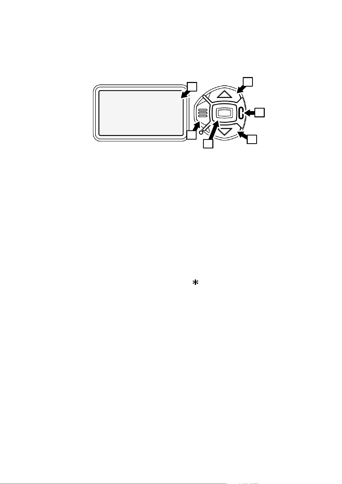
32 Martin
®
MAC Viper XIP User Manual Revision E
Control panel
This section explains how to use the fixture’s onboard control panel and control menus. You can find a
complete map of the control menu structure in ‘Control menus’ on page 41.
A – Control panel display
B – Menu button
C – Enter button
D – Up button
E – Down button
F – Status LED
When the fixture is powered on, it first boots and resets, then it displays its DMX address (or its fixture
ID number, if one has been set) and any status messages in the display A.
The display can be set to automatically rotate to match standing or hanging fixture orientation in the
PERSONALITY → DISPLAY menu or the Shortcuts menu (see “Shortcuts” on page 33).
Using the control panel
• Press the MENU button B or Enter button C to access the menus.
• Use the UP and DOWN buttons D and E to scroll up and down menus.
• Press the ENTER button C to enter a menu or make a selection.
• The currently selected menu item is indicated by a star:
• Press the MENU button B to step backwards through the menus.
Status LED
The LED F next to the control buttons indicates fixture status by showing a color and DMX status by
flashing or lighting constantly:
• GREEN: All parameters normal.
• AMBER: Warning (service interval exceeded, for example).
If ERROR MODE is set to Normal, the warning message will be shown in the display. If ERROR
MODE is set to Silent, the display must be activated by pressing the Enter button C to display the
warning message.
• RED: Error detected.
- If ERROR MODE is set to NORMAL, the error message will be shown in the display.
- If ERROR MODE is set to SILENT, display the error message by entering the menus and going
to SERVICE → ERROR LIST.
• FLASHING: No DMX signal detected.
• CONSTANT: Valid DMX signal detected.
D
F
E
B
A
C
1
DMX ADDRESS
DMX RANGE 1–33

Martin
®
MAC Viper XIP User Manual Revision E 33
If a valid DMX signal is detected and there are no warnings/errors, the status LED remains active but it
turns off when the display turns off.
Battery power
Warning! The fixture’s lithium battery is not rechargeable. Do not try to recharge it. If the battery is
discharged, obtain a replacement from your Martin supplier.
The MAC Viper XIP contains a CR123A 3-volt lithium battery behind a cover next to the control panel.
The battery gives access to the most important functions in the control panel when the fixture is not
connected to AC power. The following functions are available on battery power:
• DMX address
• DMX Mode (Basic, Extended or Ludicrous)
• Fixture ID
• Personality settings
• Default fixture settings
• Information (Power On Hours and Power Cycles counters, Software version)
• Error list.
To activate the display when the fixture is not connected to power, press the MENU button B. Press
again to enter the menus. The display extinguishes after 10 seconds with no user input and the control
panel is de-activated after 1 minute with no user input. Press the MENU button B again to re-activate.
Shortcuts
If you hold the MENU button B pressed in for 2 - 3 seconds, a shortcut menu with the most important
commands appears. Select a command with the UP and DOWN buttons and press the ENTER button
C to activate, or press the MENU button B again to cancel.
• RESET ALL resets the whole fixture.
• ROTATE DISPLAY rotates the fixture’s control panel display 180°.
• FOLLOWSPOT TOGGLE puts the fixture into / takes the fixture out of Followspot Mode, and
• TOGGLE HOLD POSITION uses the pan and tilt motors to hold the head in its current position until
position hold is toggled off again (see ‘Followspot mode’ on page 19).
• SERVICE LOG executes the SERVICE LOG → EXPORT command described in ‘Service log’ on
page 31. It exports a copy of all the fixture’s stored data and settings to any USB flash drive that is
inserted in the USB port behind the battery cover.
Settings stored permanently
The following settings are stored permanently in the fixture memory and are not affected by powering
the fixture off and on or by updating the fixture software:
• DMX address
• DMX Mode
• Fixture ID
• Personality settings (pan/tilt, cooling, dimming curve, DMX reset, effect shortcuts, display settings,
error mode, etc.)
• Resettable and non-resettable counters
• Service settings (adjustment, calibration)
These settings can be returned to factory defaults using the control menus or via DMX.

34 Martin
®
MAC Viper XIP User Manual Revision E
Activating service mode
Holding the MENU and ENTER buttons both pressed in while powering the fixture on puts the fixture
into service mode, in which pan and tilt are disabled and a SERV warning appears in the display.
Service mode removes the risk of unexpected head movement during service adjustments.
To take the fixture out of SERVICE mode, power the fixture off, then reapply power and allow the
fixture to start normally.

Martin
®
MAC Viper XIP User Manual Revision E 35
Using RDM
RDM can be used to adjust many fixture settings and view readouts. This chapter gives information on
using the Martin Companion Windows software application to set up and manage the MAC Viper XIP
via RDM. While we recommend the use of Martin Companion, most of the commonly available RDM
controllers also support the MAC Viper XIP. Check with the controller manufacturer if you cannot find
the Martin MAC Viper XIP in the list of supported fixtures. The exact procedures and command names
used by different RDM controllers vary.
Setting up single or multiple fixtures
You can set behavior in one fixture by sending a unicast RDM command to that one fixture only, or you
can set behavior in all the fixtures on the data link by sending a broadcast RDM command to all the
fixtures.
Martin Companion
®
and RDM
To set up MAC Viper XIP fixtures via RDM, we recommend using the Martin Companion Cable PC-
to-DMX interface that is available as an accessory from Martin suppliers. This tool plugs into the USB
port of a Windows PC and connects to Martin fixtures over the DMX data link via a 5-pin XLR
connector. You can also connect the fixtures via standard network cables to a PC running Martin
Companion Desktop.
The Martin Companion Cable is designed to work together with the Martin Companion Desktop
software suite for Windows desktop and laptop PCs. Martin Companion Desktop can be downloaded
free of charge from the Martin website at www.martin.com. Martin Companion will always offer the
latest MAC Viper XIP features and firmware when your PC is connected to the Internet.
Instructions for connecting the Martin Companion Cable are supplied with the tool and can also be
downloaded from the Martin website.
Martin Companion offers the following features:
• Simple PC-based user interface
• Update of fixture firmware
• RDM configuration and DMX addressing
• Stand-alone show programming with automatic start when fixtures are powered on.
RDM functions
A full list of the RDM functions that MAC Viper XIP fixtures support is given at the end of this chapter.
We refer to these functions using the more specific term ‘PIDs’ (‘Parameter IDs’).
Fixture discovery
Before you can communicate with fixtures using RDM, you must send a fixture discovery command to
all the devices on the data link so that the RDM controller can identify them. It does this by retrieving
each device’s factory-set unique identifier (UID). This process can take some time, depending on the
number of devices on the link.
To identify the fixtures on the link:
1. Check that the fixtures are correctly connected to the RDM controller on the data link and that
power is applied to all fixtures.
2. Send a discovery command via RDM (Martin Companion does this automatically as soon as the
cable is connected).
3. Give the controller time to identify the devices on the link and prepare for communication with the
devices.

36 Martin
®
MAC Viper XIP User Manual Revision E
Supported parameters
MAC Viper XIP fixtures can communicate their supported control parameters to the RDM controller and
give brief information on each parameter.
Example: setting a DMX address
You can set the DMX address of a fixture (or fixtures) on the data link via RDM. An example procedure
from Martin Companion v. 2.0 might look like this, but the procedure will vary depending on which RDM
controller you use:
1. Check that fixtures are powered on a connected to data over the DMX/RDM link.
2. Connect the Martin Companion Cable to your computer and to the DMX/RDM link.
3. Start the Martin Companion application.
4. Navigate to the RDM view in Martin Companion.
5. Wait until RDM Discovery has completed. This happens automatically, you just need to wait for the
Discovery icon top right to stop blinking.
6. Navigate to the Patch tab and check the Mode and Address columns.
7. Update the values in those columns to change the DMX mode and/or DMX start address for the
selected fixtures.
Status messages
The MAC Viper XIP features a self-diagnostic system that detects any issues concerning correct
operation or safety (temperature that exceeds safe level, for example) and communicates the issues as
status messages or warnings. These messages can be useful in connection with service and
maintenance. Error messages appear in the fixture’s control panel display, but you can also call them
up via RDM.
It is possible to:
• Call up a list of any status messages that the fixture has stored in memory.
• View information on the messages.
• Clear the stored list of status messages.
RDM functions
MAC Viper XIP fixtures support the following RDM PIDs:
PID
Name
Description
GET
SET
Device discovery
0x0001
DISC_UNIQUE_BRANCH
Fixture discovery
N/A
N/A
0x0002
DISC_MUTE
Fixture discovery
N/A
N/A
0x0003
DISC_UN_MUTE
Fixture discovery
N/A
N/A
Device information
0x0060
DEVICE_INFO
Get basic fixture info
✓
0x0080
DEVICE_MODEL_DESCRIPTION
Product name
✓
0x0081
MANUFACTURER_LABEL
Manufacturer name
✓
0x0082
DEVICE_LABEL
Info label (user-
settable)
✓
✓
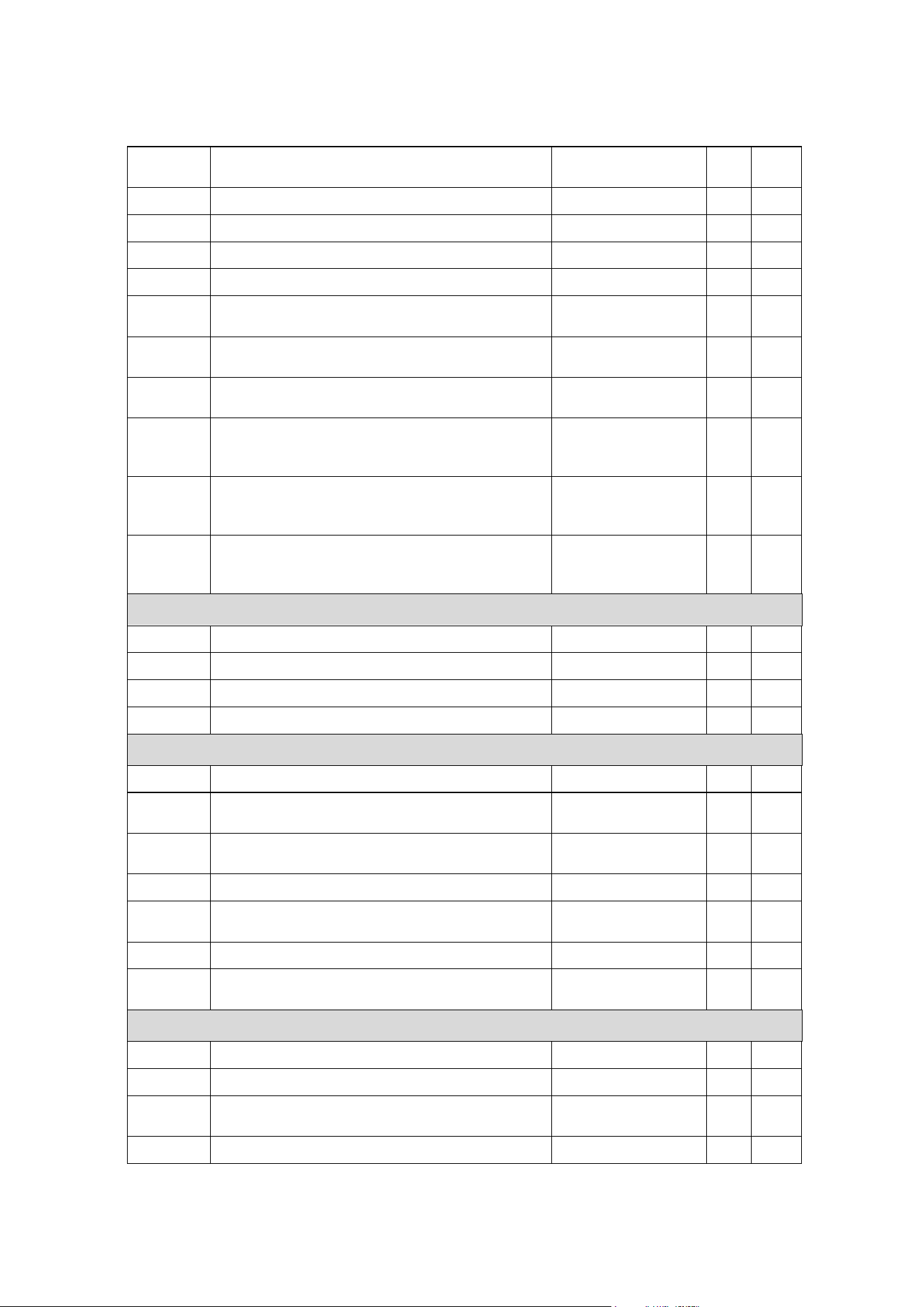
Martin
®
MAC Viper XIP User Manual Revision E 37
PID
Name
Description
GET
SET
0x8003
FIXTURE_ID
Fixture number (user-
settable)
✓
✓
0x8700
SERIAL_NUMBER
Fixture serial number
✓
0x00C0
SOFTWARE_VERSION_LABEL
Firmware version
✓
0x0200
SENSOR_DEFINITION
Sensor description
✓
0x0201
SENSOR_VALUE
Sensor value
✓
✓
0x0400
DEVICE_HOURS
Fixture hours counter
(resettable)
✓
✓
0x0401
LED_HOURS
Fixture LED hours
counter (resettable)
✓
✓
0x0405
DEVICE_POWER_CYCLES
Fixture power cycles
counter (resettable)
✓
✓
0x870A
DEVICE_HOURS_TOTAL
Read fixture hours
counter (non-
resettable)
✓
0x870B
LAMP_HOURS_TOTAL
Read LED hours
counter (non-
resettable)
✓
0x870C
POWER_CYCLES_TOTAL
Read Fixture power
cycles counter (non-
resettable)
✓
DMX setup
0x00E0
DMX_PERSONALITY
DMX mode
✓
✓
0x00E1
DMX_PERSONALITY_DESCRIPTION
DMX mode details
✓
0x00F0
DMX_START_ADDRESS
DMX start address
✓
✓
0x0121
SLOT_DESCRIPTION
DMX channel details
✓
Ethernet setup
0x0700
LIST_INTERFACES
List Ethernet ports
✓
0x0701
INTERFACE_LABEL
Name of Ethernet
port
✓
0x0702
INTERFACE_HARDWARE_ADDRESS_TYPE1
MAC address of
Ethernet Port
✓
0x0703
IPV4_DHCP_MODE
Enable DHCP client
✓
0x0705
IPV4_CURRENT_ADDRESS
Get current IP
address
✓
0x0706
IPV4_STATIC_ADDRESS
Set static IP address
✓
✓
0x0709
INTERFACE_APPLY_CONFIGURATION
Apply Ethernet
configuration
✓
Device management
0x0050
SUPPORTED_PARAMETERS
Parameter discovery
✓
0x0051
PARAMETER_DESCRIPTION
Parameter discovery
✓
0x0090
FACTORY_DEFAULTS
Reset to factory
defaults
✓
✓
0x1000
IDENTIFY_DEVICE
Identify fixture in rig
✓
✓

38 Martin
®
MAC Viper XIP User Manual Revision E
PID
Name
Description
GET
SET
0x1001
RESET_DEVICE
Reset fixture
✓
0x1020
PERFORM_SELFTEST
Run self-test
✓
✓
0x1021
SELF_TEST_DESCRIPTION
Self-test description
✓
0x0500
DISPLAY_INVERT
Flip display
✓
✓
0x0501
DISPLAY_LEVEL
Set display intensity
✓
✓
0x0600
PAN_INVERT
Invert pan
✓
✓
0x0601
TILT_INVERT
Invert tilt
✓
✓
0x8001
DMX_RESET
Enable fixture
resettable via DMX
✓
✓
0x8301
EFFECT_SPEED
Set effects speed
✓
✓
0x8302
EFFECT_SHORTCUTS_ENABLE
Enable effect
shortcuts (parameter
shortcuts)
✓
✓
0x8308
DISPLAY_ERRORS_ENABLE
Show errors in
display
✓
✓
0x8310
DIMMER_CURVE
Set dimmer curve
✓
✓
0x8004
COLOR_MODE
Set color mode
✓
✓
0x8311
FOCUS_TRACKING
Set focus tracking
✓
✓
0x8325
VIDEO_TRACKING
Set video tracking
✓
✓
0x8312
DISPLAY_AUTO_OFF
Enable onboard
display auto off
✓
✓
0x8326
DISPLAY_CONTRAST
Set onboard display
contrast
✓
✓
0x8329
HIBERNATION_MODE
Enable hibernation
mode
✓
✓
0x832A
TUNGSTEN_MODE
Enable tungsten
mode
✓
✓
0x832D
GOBO_CT_CORRECTION
Enable CT correction
when gobo deployed
✓
✓
0x8330
STUDIO_MODE
Off, Studio Mode 1,
Studio Mode 2
✓
✓
0x8331
KEYLIGHT_CALIBRATION
Keylight calibration
Auto / Manual / Off
✓
✓
0x8337
OUTDOOR_ACTIONS
0 = Stop outdoor
actions 2 = Run dry
off function, 3 = Go to
safe parking position,
✓
✓
0x833E
FRAMING_MODE
Framing options
Standard / Legacy
✓
✓
0x8400
PAN_TILT_SPEED
Set P/T speed
✓
✓
0x8402
PAN_TILT_LIMITATION_ENABLE
Enable P/T limits
✓
✓
0x8403
PAN_LIMITATION_MINIMUM
Pan minimum limit
✓
✓
0x8404
PAN_LIMITATION_MAXIMUM
Pan maximum limit
✓
✓
0x8405
TILT_LIMITATION_MINIMUM
Tilt minimum limit
✓
✓
Martin
®
MAC Viper XIP User Manual Revision E 39
PID
Name
Description
GET
SET
0x8406
TILT_LIMITATION_MAXIMUM
Tilt maximum limit
✓
✓
0x8409
PAN_TILT_LIMITATION_RESET
Reset P/T limits
✓
0x8500
FOLLOW_SPOT_MODE_ENABLE
Enable followspot
mode
✓
✓
0x8603
FAN_CLEAN
Activate fan cleaning
✓
✓
0x8604
FAN_MODE
Select cooling fan
mode
✓
✓
Stand-alone control via Martin Companion
0x1030
CAPTURE_PRESET
Capture current ‘look’
and store as preset
✓
0x1031
PRESET_PLAYBACK
Play back any of the
stored presets
✓
✓
0x8220
MANUAL_MODE_OVERRIDE
Override DMX control
with values sent via
RDM
✓
✓
0x810B
PRESET_PLAYBACK_LIMIT
Sets total number of
scenes in Stand-
Alone mode
✓
✓
0x8101
SYNCHRONIZED
Sets fixture to
Individual, Sync Host
or Sync Client Stand-
Alone Mode
✓
✓
0x810C
OFFLINE_MODE
Behavior when fixture
is not receiving DMX:
Hold Last Look or
Run Stand-Alone
Show
✓
✓
0x810D
STAND-ALONE_CTRL_MODE
Gets the currently
setup stand-alone
control mode (the
control mode for the
currently
programmed scene).
✓
Status messages
0x0020
QUEUED_MESSAGE
Get queued
messages
✓
0x0030
STATUS_MESSAGES
Get status/error
information
✓
0x0031
STATUS_ID_DESCRIPTION
Status/error
description
✓
0x0032
CLEAR_STATUS_ID
Clear status/error
queue
✓
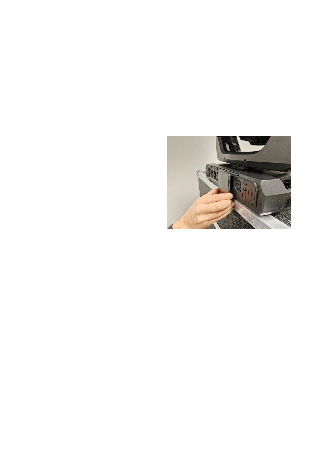
40 Martin
®
MAC Viper XIP User Manual Revision E
Using NFC
The MAC Viper XIP has an NFC interface which lets you configure and read out information from the
fixture using an NFC-capable cellphone with the Martin Companion Mobile app (available for Android
and iOS) installed.
You can carry out the following actions via the NFC interface using the Martin Companion app:
• Adjust all the settings that are available in the fixture’s onboard control menus (set DMX mode, set
DMX address, select dimmer curve, select fan mode etc.)
• Monitor the fixture (read out fixture sensor data, error codes, usage data, serial numbers, firmware
version etc.)
• Trigger quick actions on the fixture (reset to factory defaults, reset pan/tilt limits, run a self-test etc.)
To use the NFC interface:
1. Download the Martin Companion app to your
cellphone from the Apple App Store or
Google Play Store.
2. Check that NFC is enabled on the cellphone.
3. Hold the cellphone with its NFC antenna
directly in front of the fixture display as shown
in the photo on the right. The fixture’s NFC
antenna is located directly behind the control
panel display.
The location of the cellphone NFC antenna is
different from phone to phone. Please refer to
your cellphone manual if you are not sure
about the placement of the NFC antenna.
The fixture’s NFC interface is also available when the fixture is powered off, even if the fixture’s internal
battery is discharged or missing.
The status LED in the control panel flashes faster when NFC communication is taking place.
We recommend that you always use the latest version of the Martin Companion app.
Martin
®
MAC Viper XIP User Manual Revision E 41
Control menus
The following commands are available in the fixture’s control panel. Note that commands can also be
available using RDM, using DMX on the Control/Settings channel, using P3 with a Martin P3 System
Controller or using Martin Companion Mobile via NFC.
Default settings are given in bold print.
Menus marked with a battery icon below are available when the fixture is not connected to
power.
Menu level 1
Menu level 2
Menu level 3
Notes
DMX SETUP
DMX ADDRESS
1 - XXX
Set DMX address (default address =
1). The DMX address range is limited
so that the fixture will always have
enough DMX channels within the 512
available.
CONTROL MODE
BASIC
Set DMX control mode
EXTENDED
LUDICROUS
DMX UNIVERSE
1 - 63999
Set DMX universe.
WIRELESS
NO MODULE ATTACHED
The content of this menu depends on the manufacturer and model of the UCM
(Universal Connect Module) that was plugged into the fixture. See that module’s
documentation for details.
ETHERNET SETUP
IP ADDRESS
XXX.XXX.XXX.XXX
Display fixture’s static IP address
PART 1 MSB
Set far left block (most significant byte)
of IP address
PART 2
Set middle left block of IP address
PART 3
Set middle right block of IP address
PART 4 LSB
Set far right block (least significant
byte) of IP address
SUBNET MASK
XXX.XXX.XXX.XXX
EDIT SUBNET
MASK
XXX.XXX.XXX.XXX
Display fixture’s subnet mask
XXX.XXX.XXX.XXX
Set subnet mask with 1-bit increments
from the left
MAC ADDRESS
XX:XX:XX:XX:XX:XX
Display fixture’s MAC address
RESET IP SETUP
RESET
ARE YOU SURE?
→YES/NO
Reset static IP address and subnet
mask to factory default values – fixture
auto-generates its own IP address
based on its MAC address
FIXTURE ID
0 - 9999
User-settable 4-digit fixture ID number
(default = 0)
42 Martin
®
MAC Viper XIP User Manual Revision E
PERSONALITY
PAN/TILT
PAN INVERT
ON/OFF
Inverse DMX pan control: right → left
TILT INVERT
ON/OFF
Inverse DMX tilt control: down → up
FOLLOWSPOT
MODE
ON/OFF
Enable followspot mode: pan/tilt
motors disabled, head can be moved
manually
TOGGLE HOLD
Holds head in current position
NB: Only available in shortcut menu!
LIMIT PAN/TILT
LIMIT ENABLE
ON/OFF
Enable limits for pan and tilt
PAN MIN → degrees
Set minimum pan angle limit
PAN MAX → degrees
Set maximum pan angle limit
TILT MIN → degrees
Set minimum tilt angle limit
TILT MAX → degrees
Set maximum tilt angle limit
RESET PAN / TILT
LIMITS
Confirm with: ARE YOU SURE?
YES/NO
Returns fixture to default pan/tilt limits.
SPEED
PAN/TILT
FAST
Adjust speed of pan and tilt movement
SMOOTH
STANDARD
EFFECT
FAST
Adjust speed of effects movement
SMOOTH
STANDARD
FOLLOW P/T
Effects speed follows pan/tilt speed
setting
DIMMER CURVE
S-CURVE
S-curve (fixture emulates incandescent
lamp voltage linear RMS dimming
curve)
INV SQ LAW
Inverse square law dimming curve
SQUARE LAW
Square law dimming curve
LINEAR
Optically linear dimming curve
TUNGSTEN
EMULATOR
ON
Color temperature and dimming
characteristics emulate incandescent
tungsten lamp behavior
OFF
COLOR MODE
DIRECT COLOR
Direct control of CMY flags
CALIBRATED COLOR
Color mixing optimized for even color
rendition across multiple fixtures
EXTENDED GAMUT
Color mixing optimized for saturation
FOCUS TRACKING
FAR
Focus tracks zoom position
MEDIUM
NEAR
DISABLED
VIDEO TRACKING
ENABLED
Color fading optimized for speed of
color changes
DISABLED
Color fading optimized for smoothness

Martin
®
MAC Viper XIP User Manual Revision E 43
DMX RESET
ON
Fixture can be reset via DMX
OFF
Fixture cannot be reset via DMX
EFFECT
SHORTCUT
ON
Effects take shortest route during
changes, crossing open positions if
necessary
OFF
Effects avoid open positions during
effects changes
COOLING MODE
CONSTANT FAN FULL
Fans optimized for maximum light
intensity, fans run at full speed, light
intensity reduced if necessary to keep
fixture within temperature limits
CONSTANT FAN MEDIUM
Fans run at medium speed, light
intensity reduced if necessary to keep
fixture within temperature limits
CONSTANT FAN LOW
Fans run at low speed, light intensity
reduced if necessary to keep fixture
within temperature limits
CONSTANT FAN ULOW
Fans optimized for lowest noise, fans
run at ultra-low speed, light intensity
reduced if necessary to keep fixture
within temperature limits
REGULATED FANS
Compromise between light intensity
and quietness, fan speed temperature-
regulated, light intensity only reduced if
fans reach full speed and further action
necessary to keep fixture within
temperature limits
STUDIO MODE
OFF
STUDIO MODE 1
Limits output intensity by 10% to
reduce noise in REGULATED FANS
cooling mode
STUDIO MODE 2
Limits output intensity by 20% to
reduce noise in REGULATED FANS
cooling mode
GOBO CT
CORRECTION
ENABLED
Automatic color temperature correction
when gobo is inserted into beam
DISABLED
KEY LIGHT
CALIBRATION
OFF
Key light calibration disabled
MANUAL
User can manually change CMY
values to adjust keylight calibration
AUTOMATIC
CMY calibration values are
automatically calculated
44 Martin
®
MAC Viper XIP User Manual Revision E
DISPLAY
DISPLAY SLEEP
10 MINUTES
Control panel display goes into sleep mode
10 minutes after last key press
5 MINUTES
Control panel display goes into sleep
mode 5 minutes after last key press
2 MINUTES
Control panel display goes into sleep
mode 2 minutes after last key press
ON
Control panel permanently on
DISPLAY
INTENSITY
10 ... 100
Set control panel display intensity in %
(default = 50%)
DISPLAY ROTATION
ROTATE 180
Control panel display inverted
NORMAL
Control panel display orientation
normal
DISPLAY
CONTRAST
3 … 100
Set control panel display contrast
(default = 50%)
ERROR MODE
SILENT
Disable error messages and warnings
in display (the status LED will still light
to indicate fixture status if an error has
been detected or the fixture has a
warning)
NORMAL
Enable error messages and warnings
in control panel display
HIBERNATION
MODE
ON
Enable Hibernation Mode (light output
set to zero, all effect movement
disabled)
OFF
Disable Hibernation Mode
FRAMING MODE
LEGACY
Blade insertion is limited so that max.
DMX value for insertion gives 50%
insertion. Corners of angled blades
also reach max. 50% insertion.
STANDARD
Framing is controlled with designated
primary and secondary blades.
Secondary blades must make room for
primary blades, with angle as first
priority.
STAND-ALONE
OFFLINE MODE
RUN STAND-ALONE
SHOW
Stand-Alone mode enabled / disabled
HOLD LAST LOOK
STAND-ALONE
MODE
INDIVIDUAL
Fixture runs its own stand-alone show
and ignores all external stand-alone
synchronizing signals.
SYNC HOST
Fixture sends synchronizing stand-
alone signals.
SYNC CLIENT
Fixture listens for synchronizing stand-
alone signals. If it does not receive
synchronizing signals, it does not show
its stand-alone show.
RECORD CURRENT
LOOK
SURE? Y/N
Stores current look as single-scene
stand-alone show.
Martin
®
MAC Viper XIP User Manual Revision E 45
DEFAULT SETTINGS
FACTORY
DEFAULT
LOAD
ARE YOU SURE?
→ YES/NO
Return all settings (except calibrations)
to factory defaults
CUSTOM 1
LOAD
ARE YOU SURE?
→ YES/NO
Load Custom Settings 1
SAVE
ARE YOU SURE?
→ YES/NO
Save current settings as Custom
Settings 1
CUSTOM 2
LOAD
ARE YOU SURE?
→ YES/NO
Load Custom Settings 2
SAVE
ARE YOU SURE?
→ YES/NO
Save current settings as Custom
Settings 2
CUSTOM 3
LOAD
ARE YOU SURE?
→ YES/NO
Load Custom Settings 3
SAVE
ARE YOU SURE?
→ YES/NO
Save current settings as Custom
Settings 3
INFORMATION
POWER ON TIME
TOTAL
0 … XXX HR
Display number of hours fixture has
been powered on since manufacture
(not user-resettable)
RESETTABLE
0 … XXX HR
Display number of hours fixture has
been powered on since last counter
reset
CLEAR COUNTER?
→ YES/NO
Reset counter
POWER ON
CYCLES
TOTAL
0 … XXX HR
Display number of times fixture has
been powered on since manufacture
(not user-resettable)
RESETTABLE
0 … XX HR
Display number of times fixture has
been powered on since last counter
reset
CLEAR COUNTER?
→ YES/NO
Reset counter
LED ON TIME
TOTAL
0 … XX HR
Display number of hours LEDs have
been powered on since manufacture
(not user-resettable)
RESETTABLE
0 … XX HR
Display number of hours LEDs have
been powered on since last counter
reset
CLEAR COUNTER?
→ YES/NO
Reset counter
SW VERSION
XX.XX.XX
Display currently active firmware
(fixture software) version
RDM UID
4D50.XXXXXXXX
Display fixture’s unique RDM ID
FAN SPEEDS
HEAD FAN 1 ...
BASE FAN 1 …
0 … XXX RPM
Scroll to display current speed of
cooling fans
46 Martin
®
MAC Viper XIP User Manual Revision E
TEMPERATURES
(since last fixture
reset)
UI…LED BOARD
CURRENT / MIN /
MAX X C
Scroll through PCB temperature
sensors, then display current, minimum
and maximum temperature in °C of
PCBs since fixture was last reset /
powered on
DMX LIVE
SOURCE
NO INPUT / DMX / ART-NET / SACN / P3 /
UCM
Display current control data source
(UCM = Universal Connect Module)
RATE
0 – 44 Hz
DMX transmission speed in packets
per second
QUALITY
0 – 100%
Percentage of packets received
START CODE
0 – 255
Value of DMX start code
STROBE … FX
SYNC
XXX
Scroll to see values being received on
each DMX channel
TEST
TEST ALL
DIMMER … TILT
Run test sequence of all functions.
To test a specific function, use
UP/DOWN buttons to scroll through
functions.
Press ENTER to pause and press
again to restart test sequence.
Press MENU button to exit test.
TEST LEDS
DIMMER
Run test sequence of LEDs only.
Press MENU button to exit test
TEST EFFECTS
GOBO WHEEL…FOCUS
Run test sequence of effects.
To test a specific effect, use
UP/DOWN buttons to scroll through
effects.
Press ENTER to pause and press
again to restart test sequence.
Press MENU button to exit test.
TEST PAN/TILT
PAN
Run test sequence of pan functions.
Press MENU button to exit test
TILT
Run test sequence of tilt functions.
Press MENU button to exit test
MANUAL CONTROL
RESET
Reset fixture
STROBE
…
FX1, FX1 ADJUST,
FX2, FX2 ADJUST,
FX SYNC
Scroll through effects, then manually
control an effect
SERVICE
ERROR LIST
Empty or up to 20 errors
Show all error and warning messages
stored in memory
FAN CLEAN
OFF
Run cooling fans at high speed to help
dislodge dust and debris
ON

Martin
®
MAC Viper XIP User Manual Revision E 47
PAN/TILT
FEEDBACK
OFF
Enable/disable pan/tilt position
feedback system
ON
ADJUST
Important! For use
by (or with guidance
from) Martin Service
only!
P/T
AUTOCALIBRATION
PRESS UP →
START
Starts pan and tilt autocalibration.
Warning! Head will move! Allow room
for full pan/tilt movement.
FROST POSITION
LIGHT FROST
(FLAG 1) POSITION
Important! For use by authorized
service technicians during mechanical
adjustment only. Do not enter the
ADJUST menu without Martin service
documentation, or you may make the
fixture impossible to use correctly.
HEAVY FROST
(FLAG 2) POSITION
FRAMING
FRAMING BLADE 1
LEFT
FRAMING BLADE 1
RIGHT
…
FRAMING BLADE 4
LEFT
FRAMING BLADE 4
RIGHT
CALIBRATION
CYAN...TILT
Calibration range
(varies depending on
effect)
Scroll through effects, press Enter to
select. Adjust position and press Enter
to confirm.
LOAD DEFAULTS
LOAD
Load factory default calibration settings
SAVE DEFAULTS
SAVE
Replace factory default calibration
settings with current calibration
settings
EXPECTED
MODULES
Important! For use
by (or with guidance
from) Martin Service
only!
MODULE STATUS
PAN ... PIXEL BEAM
1: FOUND/MISSING
Lists internal effect modules that the
fixture expects to detect and reports
them as either FOUND or MISSING
UNKNOWN
MODULE
NONE AVAILABLE
No modules detected
XXXX (PAN ... PIXEL
BEAM 1)
One module has a red flashing LED on
its PCB. Identify which module has the
flashing LED, then select the module
from the UNKNOWN module list to
make it KNOWN.
DELETE MODULE
PAN ... PIXEL
BEAM 1
Caution! This action deletes module
type ID. Module will now be detected
as UNKNOWN.
CONSOLIDATE
FIXTURE
JOIN NEW UI
In case of SR NO MISMATCH
warning, JOIN NEW UI consolidates
saved data from the modules to the UI.
Apply this command after installing a
new UI.
The fixture still works if there is an "SR
NO MISMATCH" warning, but the
modules do not share
calibration/adjustment data with the UI.
JOIN NEW
MODULES
In case of a "SR NO MISMATCH"
warning, JOIN NEW MODULES
consolidates saved data from the UI to
the modules. Apply this command after
installing new modules.
The fixture still works if there is an "SR
NO MISMATCH" warning, but the UI
48 Martin
®
MAC Viper XIP User Manual Revision E
does not share calibration/adjustment
data with the modules.
OUTDOOR
ACTION
STOP / DRY OUT
Activates fixture’s drying out function
WET STATE
DRY / WET
Displays current rain sensor status
WET CURRENT
XXX MIN
Displays number of minutes fixture has
been wet since last powered on
WET TOTAL
XXX MIN
Displays total number of minutes
fixture has been wet in its lifetime
ORIENTATION
STANDING /
HANGING /
CONNECTORS UP /
CONNECTORS
DOWN / SIDEWAYS
90 CW / SIDEWAYS
90 CCW
Displays current fixture orientation
POWER SUPPLY
DC VOLTAGE
24VDC
ENABLE / DISABLE
Display 24 V / 48 V internal DC voltage
status (can be useful for service, can
indicate a blown internal fuse)
48VDC
ENABLE / DISABLE
AC VOLTAGE
CURRENT →
0 – XXX VAC
Display current mains power voltage
value
MIN →
0 – XXX VAC
Display lowest mains power voltage
value since fixture powered on
MAX →
0 – XXX VAC
Display highest mains power voltage
value since fixture powered on
FREQUENCY
XXHZ
Display current mains power AC
frequency in Hz
SERVICE LOG
NO DEVICE /
EXPORT
No USB device present /
Press ENTER to export Service Log
data to USB device
CLEAR
ARE YOU SURE?
YES/NO
Clears all saved error data
USB
NO DEVICE
No USB memory device detected at
USB port or no firmware detected on
USB memory device
UPDATING FILES
Fixture updating internal memory from
USB memory device
AVAILABLE
FIRMWARE
XX.XX.XX ...
XX.XX.XX
Select firmware from versions stored in
internal memory. Scroll to select
version, then press Enter and confirm
your choice to update.
FIXTURE TO
FIXTURE FW
UPLOAD VIA
DMX512
STOP / START /
FORCE
Set fixture to upload its firmware to all
the other fixtures of the same type on
the data link.
UPLOAD VIA ART-
NET
STOP / START /
FORCE
UPLOAD SPEED
HIGH SPEED / HIGH
STABILITY
Select fixture-to-fixture firmware upload
speed. High stability takes more time
but is more reliable.
Martin
®
MAC Viper XIP User Manual Revision E 49
DMX protocols
Basic DMX Mode
54 DMX channels
Channel
DMX Value
Function
Fade
type
Default
value
1
0–19
20–49
50–200
201–210
211–255
Strobe/shutter
Shutter closed
Shutter open
Strobe slow → fast
Shutter open
Random strobe slow → fast
Snap
30
2
0–65535
Dimmer
Closed → Open
Fade
0
3
4
0–65535
Cyan
Intensity 0 → 100%
Fade
0
5
6
0–65535
Magenta
Intensity 0 → 100%
Fade
0
7
8
0–65535
Yellow
Intensity 0 → 100%
Fade
0
9
10
0–65535
CTO
Open (5800 K) → Warm (2850 K)
Fade
0
11
12
0–37
38–113
114
115–255
CTC (Color Temperature Control)
2000 K
2000 K → 5750 K
Open (5800 K)
5850 K → 12850 K
Fade
114
13
0–126
127–128
129–255
Green/Magenta shift (tint)
Shift from Magenta / negative Duv to neutral
No shift (native / on black body curve)
Shift towards Green / positive Duv
Fade
128
14
0
1
2
3
4
5
6–23
24
25–40
41
42–57
58
59–74
75
Color wheel
Stepped selection
Open
Slot 1 (Spectral Enhancement)
Slot 2 (CTB)
Slot 3 (Deep Orange)
Slot 4 (Navy Blue)
Slot 5 (Red)
No function
Color wheel indexing
Open
Open → Slot 1
Slot 1
Slot 1 → Slot 2
Slot 2
Slot 2 → Slot 3
Slot 3
Snap
0

50 Martin
®
MAC Viper XIP User Manual Revision E
14
contd.
76–91
92
93–108
109
110–125
126
127
128–137
138–147
148–157
158–167
168–177
178–187
188–191
192–214
215–216
217–239
240
241–255
Slot 3 → Slot 4
Slot 4
Slot 4 → Slot 5
Slot 5
Slot 5 → Open
Open
No function
Color wheel shake
Shake around Open 360° → 10°
Shake around Slot 1 360° → 10°
Shake around Slot 2 360° → 10°
Shake around Slot 3 360° → 10°
Shake around Slot 4 360° → 10°
Shake around Slot 5 360° → 10°
No function
Color wheel rotation
CW rotation fast → slow
Stop (wheel stops at current position)
CCW rotation slow → fast
Random color
Stop (wheel stops at currently selected color)
Random color slow → fast
15
0
1
2
3
4
5
6
7
8–127
128–136
137–145
146–154
155–163
164–172
173–181
182–190
191
192–215
216–239
240
241–255
Gobo wheel 1 gobo selection
(add indexing or rotation on next channels)
Stepped selection
Open
Slot 1 (Time Ripples)
Slot 2 (Look Sharper)
Slot 3 (Compass)
Slot 4 (Deep Space)
Slot 5 (Radar)
Slot 6 (Short Cuts)
Slot 7 (A Lot of Spot)
No function
Gobo shake
Shake slot 1 360° → 10°
Shake slot 2 360° → 10°
Shake slot 3 360° → 10°
Shake slot 4 360° → 10°
Shake slot 5 360° → 10°
Shake slot 6 360° → 10°
Shake slot 7 360° → 10°
No function
Gobo wheel rotation
CW rotation fast → slow
CCW rotation slow → fast
Random gobo
Stop (wheel stops at currently selected gobo)
Random gobo slow → fast
Snap
0
16
0–16383
16384
16385–32767
32768–49150
49151–49152
49153–65535
Gobo wheel 1 gobo indexing/rotation
Gobo indexing
Indexing -180° → 0°
Indexed at 0°
Indexing 0° → +180°
Gobo rotation
CW gobo rotation fast → slow
Stop (gobo stops at current position)
CCW gobo rotation slow → fast
Fade
16384
17
Martin
®
MAC Viper XIP User Manual Revision E 51
18
0
1
2
3
4
5
6
7
8–127
128–136
137–145
146–154
155–163
164–172
173–181
182–190
191
192–215
216–239
240
241–255
Gobo wheel 2 gobo selection
(add indexing or rotation on next channels)
Stepped selection
Open
Slot 1 (String Theory)
Slot 2 (Hazey Waves)
Slot 3 (Limbo)
Slot 4 (Up Is Down)
Slot 5 (Brush Up)
Slot 6 (Sponge)
Slot 7 (All Wrapped Up)
No function
Gobo shake
Shake slot 1 360° → 10°
Shake slot 2 360° → 10°
Shake slot 3 360° → 10°
Shake slot 4 360° → 10°
Shake slot 5 360° → 10°
Shake slot 6 360° → 10°
Shake slot 7 360° → 10°
No function
Gobo wheel rotation
CW rotation fast → slow
CCW rotation slow → fast
Random gobo
Stop (wheel stops at currently selected gobo)
Random gobo slow → fast
Snap
0
19
0–16383
16384
16385–32767
32768–49150
49151–49152
49153–65535
Gobo wheel 2 gobo indexing/rotation
Gobo indexing
Indexing -180° → 0°
Indexed at 0°
Indexing 0° → +180°
Gobo rotation
CW rotation fast → slow
Stop (gobo stops at current position)
CCW rotation slow → fast
Snap
16384
20
21
0
1
2
3
4–23
24
25–74
75
76–126
127
128–148
149–169
170–190
191
Animation wheel insertion
(add indexing or rotation on next channels)
Stepped insertion
Open
Horizontal pattern
Diagonal pattern
Vertical pattern
No function
Continuous insertion
Open
Wheel insertion
Horizontal pattern
Diagonal patterns
Vertical pattern
Wheel shake
Horizontal pattern shake slow → fast
Diagonal pattern shake slow → fast
Vertical pattern shake slow → fast
No function
Snap
0

52 Martin
®
MAC Viper XIP User Manual Revision E
21
contd.
192
193–239
240
241–255
Bounce
Stop (wheel stops at current position)
Bounce between horizontal and vertical
slow → fast
Random pattern
Stop (wheel stops at current pattern)
Random patterns between horizontal and
vertical slow → fast
22
0–16383
16384
16385–32767
32768–49150
49151–49152
49153–65535
Animation wheel indexing/rotation
Animation wheel indexing
Indexing -180° → 0°
Indexed at 0°
Indexing 0° → +180°
Animation wheel rotation
CW rotation fast → slow
Stop (wheel stops at current position)
CCW rotation slow → fast
Fade
16384
23
24
0–255
Light Frost (Frost 1)
No frost → full frost
Fade
0
25
0–255
Heavy Frost (Frost 2)
No frost → full frost
Fade
0
26
0
1
2–127
128–191
192–255
Prism selection (select indexed angle or
rotation on next channels)
Stepped selection
Open
Prism 1
No function
Prism shake
Shake prism slow → fast
No function
Snap
0
27
0–16383
16384
16385–32767
32768–49150
49151–49152
49153–65535
Prism indexing/rotation
Prism indexing
Indexing -180° → 0°
Prism indexed at 0°
Indexing 0° → +180°
Prism rotation
CW rotation fast → slow
Stop (prism stops at current position)
CCW rotation slow → fast
Fade
16384
28
29
0–191
192
193–223
224
225–255
Iris
Iris opening
Open → closed
Opening pulse
Stop (iris stops at current position)
Opening pulse slow → fast
Closing pulse
Stop (iris stops at current position)
Closing pulse slow → fast
Fade
0
30
0–65535
Zoom
Wide → narrow
Fade
32768
31
32
0–65535
Focus
Infinity → near
Fade
32768
33

Martin
®
MAC Viper XIP User Manual Revision E 53
34
0–255
Framing blade 1 position
Out → in
Fade
0
35
0–126
127–128
129–255
Framing blade 1 angle
Minimum
Parallel
Maximum
Fade
128
36
0–255
Framing blade 2 position
Out → in
Fade
0
37
0–126
127–128
129–255
Framing blade 2 angle
Minimum
Parallel
Maximum
Fade
128
38
0–255
Framing blade 3 position
Out → in
Fade
0
39
0–126
127–128
129–255
Framing blade 3 angle
Minimum
Parallel
Maximum
Fade
128
40
0–255
Framing blade 4 position
Out → in
Fade
0
41
0–126
127–128
129–255
Framing blade 4 angle
Minimum
Parallel
Maximum
Fade
128
42
0–126
127–128
129–255
Framing rotation
Minimum
Parallel
Maximum
Fade
128
43
0–65535
Pan
Left → right
Fade
32768
44
45
0–65535
Tilt
Forward → backward
Fade
32768
46
47
Fixture Control/Settings – see ‘Control/Settings DMX channel’ on page 62
48
0
1–127
128
129–254
255
LED Frequency
Hybrid dimming
Variable -2% → 0%
2400 Hz
Variable 0% → +2%
No function
Snap
128

54 Martin
®
MAC Viper XIP User Manual Revision E
49
0–26
27–228
229–255
P3 Mix
DMX Mode
Intensity and colors fully controlled by DMX,
P3 pixel data ignored
Mixed Mode
Crossfade from DMX control of intensity and
colors to P3 control of intensity and colors:
• At 27, intensity and colors are still fully
controlled by DMX.
• Between 27 and 228, you mix/crossfade
from DMX to P3 control.
• At 228, the intensity of each of the 6 x
Animotion segments is controlled by 6 x
separate P3 pixels and color is controlled
using the average color of the six P3
pixels.
Video Mode
Intensity of 6 x Animotion segments
controlled by 6 x P3 pixels, color controlled
by DMX (DMX channels ‘color’ the P3 pixel
data)
Snap
0
50
0–255
FX 1 Select
FX Selection 1 -255
Snap
0
51
0–126
127–128
129–255
FX 1 Adjust
Backwards fast → slow
Stop
Forwards slow → fast
Fade
128
52
0–255
FX 2 Select
FX Selection 1 -255
Snap
0
53
0–126
127–128
129–255
FX 2 Adjust
Backwards fast → slow
Stop
Forwards slow → fast
Fade
128
54
0
1–35
36
37–100
101–120
121–140
141–255
FX Synchronization
No sync
Fixture offset (shift 10° → 350°)
Synchronized
No function
Random start (FX1 adjust channel controls
overall speed)
Random duration
No function
Snap
36
Martin
®
MAC Viper XIP User Manual Revision E 55
Extended DMX Mode
64 DMX channels
Channel
DMX Value
Function
Fade
type
Default
value
1
0–19
20–49
50–200
201–210
211–255
Strobe/shutter
Shutter closed
Shutter open
Strobe slow → fast
Shutter open
Random strobe slow → fast
Snap
30
2
0–65535
Dimmer
Closed → Open
Fade
0
3
4
0–65535
Cyan
Intensity 0 → 100%
Fade
0
5
6
0–65535
Magenta
Intensity 0 → 100%
Fade
0
7
8
0–65535
Yellow
Intensity 0 → 100%
Fade
0
9
10
0–65535
CTO
Open (5800 K) → Warm (2850 K)
Fade
0
11
12
0–37
38–113
114
115–255
CTC (Color Temperature Control)
2000 K
2000 K → 5750 K
Open (5800 K)
5850 K → 12850 K
Fade
114
13
0–126
127–128
129–255
Green/Magenta shift (tint)
Shift from Magenta / negative Duv to no shift
No shift (native / on black body curve)
Shift towards Green / positive Duv
Fade
128
14
0
1
2
3
4
5
6–23
24
25–40
41
42–57
58
59–74
75
76–91
92
93–108
Color wheel
Stepped selection
Open
Slot 1 (Spectral Enhancement)
Slot 2 (CTB)
Slot 3 (Deep Orange)
Slot 4 (Navy Blue)
Slot 5 (Red)
No function
Color wheel indexing
Open
Open → Slot 1
Slot 1
Slot 1 → Slot 2
Slot 2
Slot 2 → Slot 3
Slot 3
Slot 3 → Slot 4
Slot 4
Slot 4 → Slot 5
Snap
0

56 Martin
®
MAC Viper XIP User Manual Revision E
14
contd.
109
110–125
126
127
128–137
138–147
148–157
158–167
168–177
178–187
188–191
192–214
215–216
217–239
240
241–255
Slot 5
Slot 5 → Open
Open
No function
Color wheel shake
Shake around Open 360° → 10°
Shake around Slot 1 360° → 10°
Shake around Slot 2 360° → 10°
Shake around Slot 3 360° → 10°
Shake around Slot 4 360° → 10°
Shake around Slot 5 360° → 10°
No function
Color wheel rotation
CW rotation fast → slow
Stop (wheel stops at current position)
CCW rotation slow → fast
Random color
Stop (wheel stops at currently selected color)
Random color slow → fast
15
0
1
2
3
4
5
6
7
8–127
128–136
137–145
146–154
155–163
164–172
173–181
182–190
191
192–215
216–239
240
241–255
Gobo wheel 1 gobo selection
(add indexing or rotation on next channels)
Stepped selection
Open
Gobo 1 (Time Ripples)
Gobo 2 (Look Sharper)
Gobo 3 (Compass)
Gobo 4 (Deep Space)
Gobo 5 (Radar)
Gobo 6 (Short Cuts)
Gobo 7 (A Lot of Spot)
No function
Gobo shake
Shake Gobo 1, 360° → 10°
Shake Gobo 2, 360° → 10°
Shake Gobo 3, 360° → 10°
Shake Gobo 4, 360° → 10°
Shake Gobo 5, 360° → 10°
Shake Gobo 6, 360° → 10°
Shake Gobo 7, 360° → 10°
No function
Gobo wheel rotation
CW rotation fast → slow
CCW rotation slow → fast
Random gobo
Stop (wheel stops at currently selected gobo)
Random gobo slow → fast
Snap
0
16
0–16383
16384
16385–32767
32768–49150
49151–49152
49153–65535
Gobo wheel 1 gobo indexing/rotation
Gobo indexing
Indexing -180° → 0°
Indexed at 0°
Indexing 0° → +180°
Gobo rotation
CW gobo rotation fast → slow
Stop (gobo stops at current position)
CCW gobo rotation slow → fast
Fade
16384
17
Martin
®
MAC Viper XIP User Manual Revision E 57
18
0
1
2
3
4
5
6
7
8–127
128–136
137–145
146–154
155–163
164–172
173–181
182–190
191
192–215
216–239
240
241–255
Gobo wheel 2 gobo selection
(add indexing or rotation on next channels)
Stepped selection
Open
Gobo 1 (String Theory)
Gobo 2 (Hazey Waves)
Gobo 3 (Limbo)
Gobo 4 (Up Is Down)
Gobo 5 (Brush Up)
Gobo 6 (Sponge)
Gobo 7 (All Wrapped Up)
No function
Gobo shake
Shake Gobo 1, 360° → 10°
Shake Gobo 2, 360° → 10°
Shake Gobo 3, 360° → 10°
Shake Gobo 4, 360° → 10°
Shake Gobo 5, 360° → 10°
Shake Gobo 6, 360° → 10°
Shake Gobo 7, 360° → 10°
No function
Gobo wheel rotation
CW rotation fast → slow
CCW rotation slow → fast
Random gobo
Stop (wheel stops at currently selected gobo)
Random gobo slow → fast
Snap
0
19
0–16383
16384
16385–32767
32768–49150
49151–49152
49153–65535
Gobo wheel 2 gobo indexing/rotation
Gobo indexing
Indexing -180° → 0°
Indexed at 0°
Indexing 0° → +180°
Gobo rotation
CW rotation fast → slow
Stop (gobo stops at current position)
CCW rotation slow → fast
Snap
16384
20
21
0
1
2
3
4–23
24
25–74
75
76–126
127
128–148
149–169
170–190
191
Animation wheel insertion
(add indexing or rotation on next channels)
Stepped insertion
Open
Horizontal pattern
Diagonal pattern
Vertical pattern
No function
Continuous insertion
Open
Wheel insertion
Horizontal pattern
Diagonal patterns
Vertical pattern
Wheel shake
Horizontal pattern shake slow → fast
Diagonal pattern shake slow → fast
Vertical pattern shake slow → fast
No function
Snap
0

58 Martin
®
MAC Viper XIP User Manual Revision E
21
contd.
192
193–239
240
241–255
Bounce
Stop (wheel stops at current position)
Bounce between horizontal and vertical
slow → fast
Random pattern
Stop (wheel stops at current pattern)
Random patterns between horizontal and
vertical slow → fast
22
0–16383
16384
16385–32767
32768–49150
49151–49152
49153–65535
Animation wheel indexing/rotation
Animation wheel indexing
Wheel indexing -180° → 0°
Wheel indexed at 0°
Wheel indexing 0° → +180°
Animation wheel rotation
CW rotation fast → slow
Stop (wheel stops at current position)
CCW rotation slow → fast
Fade
16384
23
24
0–255
Light Frost (Frost 1)
No frost → full frost
Fade
0
25
0–255
Heavy Frost (Frost 2)
No frost → full frost
Fade
0
26
0
1
2–127
128–191
192–255
Prism selection (select indexed angle or
rotation on next channels)
Stepped selection
Open
Prism 1
No function
Prism shake
Shake prism slow → fast
No function
Snap
0
27
0–16383
16384
16385–32767
32768–49150
49151–49152
49153–65535
Prism indexing/rotation
Prism indexing
Prism indexing -180° → 0°
Prism indexed at 0°
Prism indexing 0° → +180°
Prism rotation
CW rotation fast → slow
Stop (prism stops at current position)
CCW rotation slow → fast
Fade
16384
28
29
0–49151
49152
49153–57343
57344
57345–65535
Iris
Iris opening
Open → closed
Opening pulse
Stop (iris stops at current position)
Opening pulse slow → fast
Closing pulse
Stop (iris stops at current position)
Closing pulse slow → fast
Fade
0
30
31
0–65535
Zoom
Wide → narrow
Fade
32768
32
33
0–65535
Focus
Infinity → Near
Fade
32768
34

Martin
®
MAC Viper XIP User Manual Revision E 59
35
0–65535
Framing blade 1 position
Out → in
Fade
0
36
37
0–32766
32767–32768
32769–65535
Framing blade 1 angle
Minimum
Parallel
Maximum
Fade
32768
38
39
0–65535
Framing blade 2 position
Out → in
Fade
0
40
41
0–32766
32767–32768
32769–65535
Framing blade 2 angle
Minimum
Parallel
Maximum
Fade
32768
42
43
0–65535
Framing blade 3 position
Out → in
Fade
0
44
45
0–32766
32767–32768
32769–65535
Framing blade 3 angle
Minimum
Parallel
Maximum
Fade
32768
46
47
0–65535
Framing blade 4 position
Out → in
Fade
0
48
49
0–32766
32767–32768
32769–65535
Framing blade 4 angle
Minimum
Parallel
Maximum
Fade
32768
50
51
0–32766
32767–32768
32769–65535
Framing rotation
Minimum
Parallel
Maximum
Fade
32768
52
53
0–65535
Pan
Left → right
Fade
32768
54
55
0–65535
Tilt
Forward → backward
Fade
32768
56
57
Fixture Control/Settings – see ‘Control/Settings DMX channel’ on page 62
58
0
1–127
128
129–254
255
LED Frequency
Hybrid dimming
Variable -2% → 0%
2400 Hz
Variable 0% → +2%
No function
Snap
128

60 Martin
®
MAC Viper XIP User Manual Revision E
59
0–26
27–228
229–255
P3 Mix
DMX Mode
Intensity and colors fully controlled by DMX,
P3 pixel data ignored
Mixed Mode
Crossfade from DMX control of intensity and
colors to P3 control of intensity and colors:
• At 27, intensity and colors are still fully
controlled by DMX.
• Between 27 and 228, you mix/crossfade
from DMX to P3 control.
• At 228, the intensity of each of the 6 x
Animotion segments is controlled by 6 x
separate P3 pixels and color is controlled
using the average color of the six P3
pixels.
Video Mode
Intensity of 6 x Animotion segments
controlled by 6 x P3 pixels, color controlled
by DMX (DMX channels ‘color’ the P3 pixel
data)
Snap
0
60
0–255
FX 1 Select
FX Selection 1 -255
Snap
0
61
0–126
127–128
129–255
FX 1 Adjust
Backwards fast → slow
Stop
Forwards slow → fast
Fade
128
62
0–255
FX 2 Select
FX Selection 1 -255
Snap
0
63
0–126
127–128
129–255
FX 2 Adjust
Backwards fast → slow
Stop
Forwards slow → fast
Fade
128
64
0
1–35
36
37–100
101–120
121–140
141–255
FX Synchronization
No sync
Fixture offset (shift 10° → 350°)
Synchronized
No function
Random start (FX1 adjust channel controls
overall speed)
Random duration
No function
Snap
36
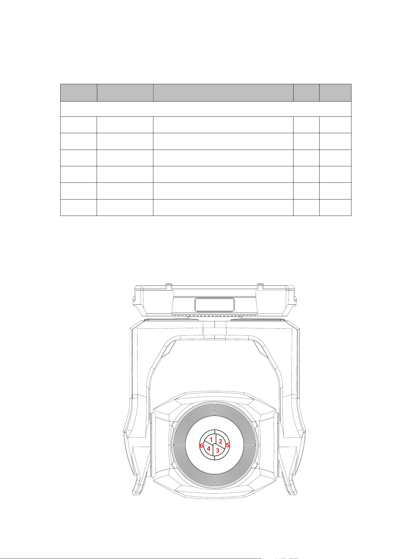
Martin
®
MAC Viper XIP User Manual Revision E 61
Ludicrous DMX Mode
70 DMX channels
Channel
DMX Value
Function
Fade
type
Default
value
Channels 1 – 64 as in Extended Mode
65
0–255
Intensity LED Segment 1
0
→
100%
Fade
255
66
0–255
Intensity LED Segment 2
0
→
100%
Fade
255
67
0–255
Intensity LED Segment 3
0
→
100%
Fade
255
68
0–255
Intensity LED Segment 4
0
→
100%
Fade
255
69
0–255
Intensity LED Segment 5
0
→
100%
Fade
255
70
0–255
Intensity LED Segment 6
0
→
100%
Fade
255
Segment numbering
Ludicrous DMX mode gives individual control of the six LED segments that make up the light engine.
The segments are numbered as shown below (fixture hanging downwards, display and connectors at
back of fixture, pan at 50%, fixture tilted forward).
62 Martin
®
MAC Viper XIP User Manual Revision E
Control/Settings DMX channel
The table below lists the control/settings functions available via DMX on the following channels:
• In Basic DMX Mode: on channel 47
• In Extended and Ludicrous DMX Modes: on channel 57.
The commands on the Control/Settings channel must be held for a certain number of seconds in order
to implement them. The required number of seconds is indicated after each command.
Channel
DMX value
Function
Fade
type
Default
value
Channel
depends
on DMX
mode
0–9
10–14
15
16
17
18
19–22
23
24
25
26
27
28
29
30
31
32
33
34
35
36
37
38
39
40
41–51
52
53
54
55
56
57
58
59–60
61
62
No function
Reset fixture (5 sec.)
No function
Reset color (5 sec.)
Reset beam (5 sec.)
Reset pan and tilt (5 sec.)
No function
Linear dimmer curve (1 sec.)
Square law dimmer curve (default, 1 sec.)
Inverse square law dimmer curve (1 sec.)
S-Curve dimmer curve (1 sec.)
Pan and tilt speed = Standard
(default, 1 sec.)
Pan and tilt speed = Fast (1 sec.)
Pan and tilt speed = Smooth (1 sec.)
Effect shortcuts = ON (default, 1 sec.)
Effect shortcuts = OFF (1 sec.)
Disable focus tracking (1 sec.)
Enable focus tracking at near distance
(1 sec.)
Enable focus tracking at medium distance
(default, 1 sec.)
Enable focus tracking at far distance
(1 sec.)
Enable video tracking (1 sec.)
Disable video tracking (default, 1 sec.)
Extended gamut mode (1 sec.)
Calibrated color mode (1 sec.)
Direct color mode (default, 1 sec.)
No function
Control panel display = ON (default, 1 sec.)
Control panel display = OFF
Regulated fan speed, fixed light output
intensity (default, 1 sec.)
Full fan speed, regulated light output
intensity (1 sec.)
Medium fan speed, regulated light output
intensity (1 sec.)
Low fan speed, regulated light output
intensity (1 sec.)
Ultra-low fan speed, regulated light output
intensity (1 sec.)
No function
Hibernation = ON (1 sec.)
Hibernation = OFF (default, 1 sec.)
Snap
0

Martin
®
MAC Viper XIP User Manual Revision E 63
63
64
65
66
67
68
69
70
71
72
73
74
75
76
77–78
79
80
81–83
84
85
86
87
88
89
90–93
94
95
96–99
100
101
102
103
104
105
106
107
108
109
110
111
112
113
114
115
116–191
192
193
194
195
196
Followspot = ON (1 sec.)
Followspot = OFF (default, 1 sec.)
Pan tilt limit = ON (1 sec.)
Pan tilt limit = OFF (default, 1 sec.)
Store lower pan limit (1 sec.)
Store upper pan limit (1 sec.)
Store lower tilt limit (1 sec.)
Store upper tilt limit (1 sec.)
Reset pan tilt limits (1 sec.)
Tungsten emulation = ON (1 sec.)
Tungsten emulation = OFF (default, 1 sec.)
Stand-alone: Record current look (5 sec.)
Offline mode = Run stand-alone show
(5 sec.)
Offline mode = Hold last look (default,
5 sec.)
No function
Enable gobo CT correction (default, 1 sec.)
Disable gobo CT correction (1 sec.)
No function
Studio mode 2 (1 sec.)
Studio mode 1 (1 sec.)
Studio mode = OFF (default, 1 sec.)
Disable keylight calibration (1 sec.)
Keylight calibration manual (1 sec.)
Keylight calibration automatic
(default, 1 sec.)
No function
Standard framing mode
Legacy framing mode
No function
Enable calibration (5 sec.)
Store pan and tilt calibration (5 sec.)
No function
Store Cyan calibration (5 sec.)
Store Magenta calibration (5 sec.)
Store Yellow calibration (5 sec.)
Store CTC calibration (5 sec.)
Store all CMYC calibration (5 sec.)
Store Rotating Gobo 1 / Current slot index
calibration (5 sec.)
Store Rotating Gobo 2 / Current slot index
calibration (5 sec.)
No function
Store beam effect/framing calibration
(5 sec.)
Store iris calibration (5 sec.)
Store focus calibration (5 sec.)
Store zoom calibration (5 sec.)
Store color wheel calibration (5 sec.)
No function
Start CTB filter keylight calibration (5 sec.)
Store CTB filter keylight calibration (5 sec.)
Start CTO flag keylight calibration (5 sec.)
Start Spectral Enhancement filter keylight
calibration (5 sec.)
Store CTO flag keylight calibration (5 sec.)

64 Martin
®
MAC Viper XIP User Manual Revision E
197
198
199
200–210
210
211
212
213
214–255
Store Spectral Enhancement filter keylight
calibration (5 sec.)
Store all calibration values except keylight
calibration (5 sec.)
Reset all calibration values to factory
default (excluding keylight calibration,
5 sec.)
No function
Outdoor: Stop actions and return to normal
operation
No function
Outdoor: Run drying off procedure (1 sec.,
stops when sequence is complete, or stop
by sending value 210)
Outdoor: Head goes immediately to safe
parking position (1 sec., return to normal
operation by sending value 210)
No function

Martin
®
MAC Viper XIP User Manual Revision E 65
FX
The table on the following pages lists the pre-programmed dynamic FX (effect macros) available in the
MAC Viper XIP. To control the FX you can:
• Select an effect, or two effects that can run simultaneously, on DMX channels 50 and 52 (Basic
Mode) or 60 and 62 (Extended and Ludicrous Modes) by sending the values listed in the table.
• Adjust effect speed on channels 51 and 53 (Basic Mode) or 61 and 63 (Extended and Ludicrous
Modes).
• Adjust synchronization of effects across different fixtures on channel 54 (Basic Mode) or 64
(Extended and Ludicrous Modes).
Effects types
Intensity FX (1-15)
These effects modulate the intensity of the output while keeping the color(s) set on the CMY and color
wheel channels and any other effects applied.
Animotion effects (32-46)
The MAC Viper XIP’s Animotion effects modulate the individual segments of the fixture's LED array
individually, giving unique animated effects.
Color FX (64-91)
These effects override the color(s) set on the CMY and color wheel channels.
Beam shaping FX (96-110)
These effects use the fixture’s iris, zoom and prism to dynamically change the shape of the beam.
Gobo and Animation FX (128-143)
These effects apply dynamic movement to gobos. Certain effects add zoom to the movement.
Gobo 1 FX are applied to the gobo that is currently selected on gobo wheel 1 and Gobo 2 FX are
applied to the gobo that is currently selected on gobo wheel 2.
Framing FX (160-194)
These effects use the fixture’s framing system to give static and dynamic beam shapes.
FX 160 (FX2 y-axis selection) is available on the FX2 Selection channel 52 in Basic Mode / 62 in
Extended and Ludicrous Modes only. Selecting FX 160 on channel 52 / 62 changes the function of
channel 53 / 63. If you select FX 160 on channel 52 / 62, channel 53 / 63 now lets you adjust the y-axis
of any FX from 161 - 194 that you select on the FX1 Selection channel 50 / 60.
FX 161 - 194 are available on the FX1 Selection channel 50 (Basic Mode) / 60 (Extended and
Ludicrous Modes) only.
Pan and tilt FX (224-235)
These effects use pan and tilt to move the beam following pre-programmed shapes.
66 Martin
®
MAC Viper XIP User Manual Revision E
FX table
DMX Value
Effect
0
No FX
Intensity FX
1
Strobe Pulse Width (when Strobe is activated on
Channel 1)
2
Wave (sine wave)
3
Step (50/50 on/off)
4
Pulse
5
Blackout Strobe
6
2x Strobe
7
3x Strobe
8
4x Strobe
9
Up, Down, Flash
10
Up, Flash, Down, Flash
11
Random Levels
12
Electric Arc
13
Atomic Lighting
14
Thunderstorm
15
Welding
16–31
No function
Animotion FX
32
Stop Motion
33
Movie Flicker
34
Random Dimmers
35
Shakey Dimmers
36
Negative Pulse
37
Positive Pulse
38
Radar Wave
39
Radar Step
40
Radar Pulse
41
Odd/Even Wave
42
Odd/Even Step
43
Odd/Even Pulse
44
5-Step Wave
45
5-Step Step
46
5-Step Pulse
47–63
No function
Color FX
64
Rainbow Wave
65
Rainbow Step
66
Rainbow Pulse
67
RGB Wave
68
RGB Step
69
RGB Pulse
70
CMY Wave
71
CMY Step
72
CMY Pulse
73
Mix to White Wave
74
Mix to White Step
75
Mix to White Pulse
76
Random Mix Wave
77
Random Mix Step
78
Random Mix Pulse
79
Random Subtle Wave
Martin
®
MAC Viper XIP User Manual Revision E 67
DMX Value
Effect
80
Red-White-Blue Fade
81
Red-White-Blue Snaps
82
Full Bumps
83
All Bumps
84
Split Bumps
85
Random Split Bumps
86
Color Shaker
87
Fire
88
Water
89
Ice
90
Hot and Cold
91
Warm and Fuzzy
92–95
No function
Beam Shaping FX
96
Iris Wave (sine wave)
97
Iris Step (50/50 on/off)
98
Iris Pulse
99
Zoom Wave (sine wave, keeps current speed mode)
100
Zoom Step (50/50 on/off, keeps current speed mode)
101
Zoom Pulse (keeps current speed mode)
102
Random Size Wave
103
Random Size Step
104
Random Size Pulse
105
Prism Quarter Tick Tock
106
Prism Half Tick Tock
107
Prism Full Tick Tock
108
Beam Splash
109
Beam Splash Invert
110
Pin to Flood (keeps current speed mode)
111–127
No function
Gobo and Animation FX
128
Gobo 1 Tick Tick Tick
129
Gobo 1 Quarter Tick Tock
130
Gobo 1 Half Tick Tock
131
Gobo 1 Full Tick Tock
132
Gobo 1 Fade Spin Zoom
133
Gobo 1 Twist
134
Gobo 1 Expand Twist
135
Gobo 1 Collapse Twist
136
Gobo 2 Tick Tick Tick
137
Gobo 2 Quarter Tick Tock
138
Gobo 2 Half Tick Tock
139
Gobo 2 Full Tick Tock
140
Gobo 2 Fade Spin Zoom
141
Gobo 2 Twist
142
Gobo 2 Expand Twist
143
Gobo 2 Collapse Twist
144-159
No function

68 Martin
®
MAC Viper XIP User Manual Revision E
DMX Value
Effect
Framing FX
Available on FX2 Select channel only
160
When selected on channel 46, FX160 enables y-axis
selection on channel 47 for FX 167-194 if one of these
is selected on channel 44.
Available on FX1 Select channel only
161
Vertical Bar Slim
162
Vertical Bar Medium
163
Vertical Bar Large
164
Horizontal Bar Slim
165
Horizontal Bar Medium
166
Horizontal Bar Large
167
Small Square
168
Medium Square
169
Large Square
170
Small Horizontal Rectangle
171
Medium Horizontal Rectangle
172
Large Horizontal Rectangle
173
Small Vertical Rectangle
174
Medium Vertical Rectangle
175
Large Vertical Rectangle
176
Small Parallelogram Left
177
Medium Parallelogram Left
178
Small Parallelogram Right
179
Medium Parallelogram Right
180
Vertical Bar Slim to Horizontal Bar Slim
181
Vertical Bar Medium to Horizontal Bar Medium
182
Vertical Bar Large to Horizontal Bar Large
183
Vertical Bar Slim to Medium Square
184
Vertical Bar Medium to Medium Square
185
Horizontal Bar Slim to Medium Square
186
Horizontal Bar Medium to Medium Square
187
Medium Square to Medium Horizontal Rectangle
188
Medium Square to Medium Vertical Rectangle
189
Medium Square to Large Horizontal Rectangle
190
Medium Square to Large Vertical Rectangle
191
Small Square to Small Parallelogram Left
192
Medium Square to Medium Parallelogram Left
193
Small Square to Small Parallelogram Right
194
Medium Square to Medium Parallelogram Right
195-223
No function

Martin
®
MAC Viper XIP User Manual Revision E 69
DMX Value
Effect
Pan/Tilt FX
224
Pan and Tilt Circle Small
225
Pan and Tilt Circle Medium
226
Pan and Tilt Circle Large
227
Pan and Tilt Figure 8 Small
228
Pan and Tilt Figure 8 Medium
229
Pan and Tilt Figure 8 Large
230
Pan and Tilt Diagonal Line Small
231
Pan and Tilt Diagonal Line Medium
232
Pan and Tilt Diagonal Line Large
233
Pan and Tilt Square Small
234
Pan and Tilt Square Medium
235
Pan and Tilt Square Large
236-255
No function
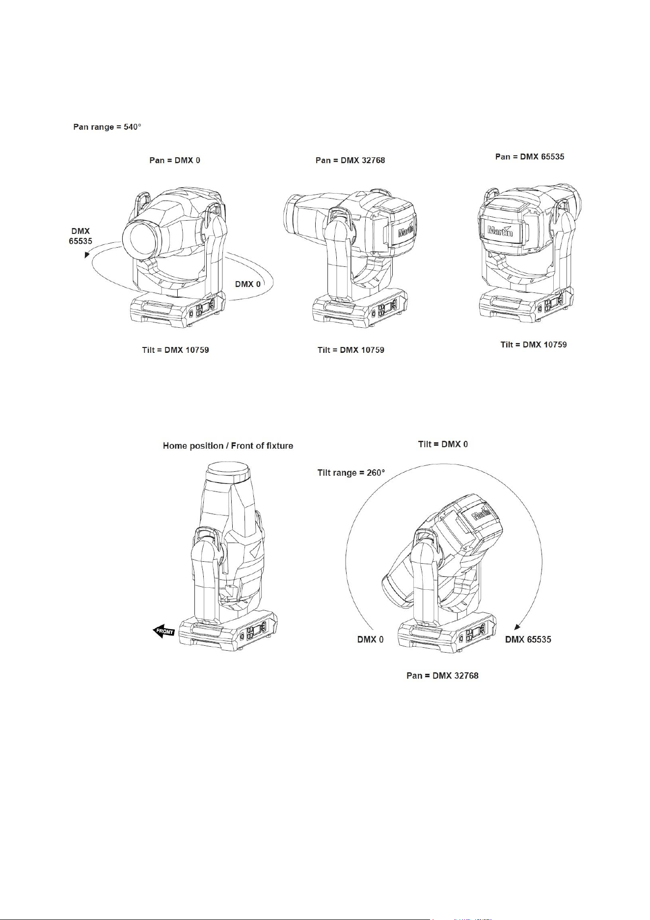
70 Martin
®
MAC Viper XIP User Manual Revision E
Pan/tilt and zoom orientation guide
Fixture shown in illustrations is for example purposes only
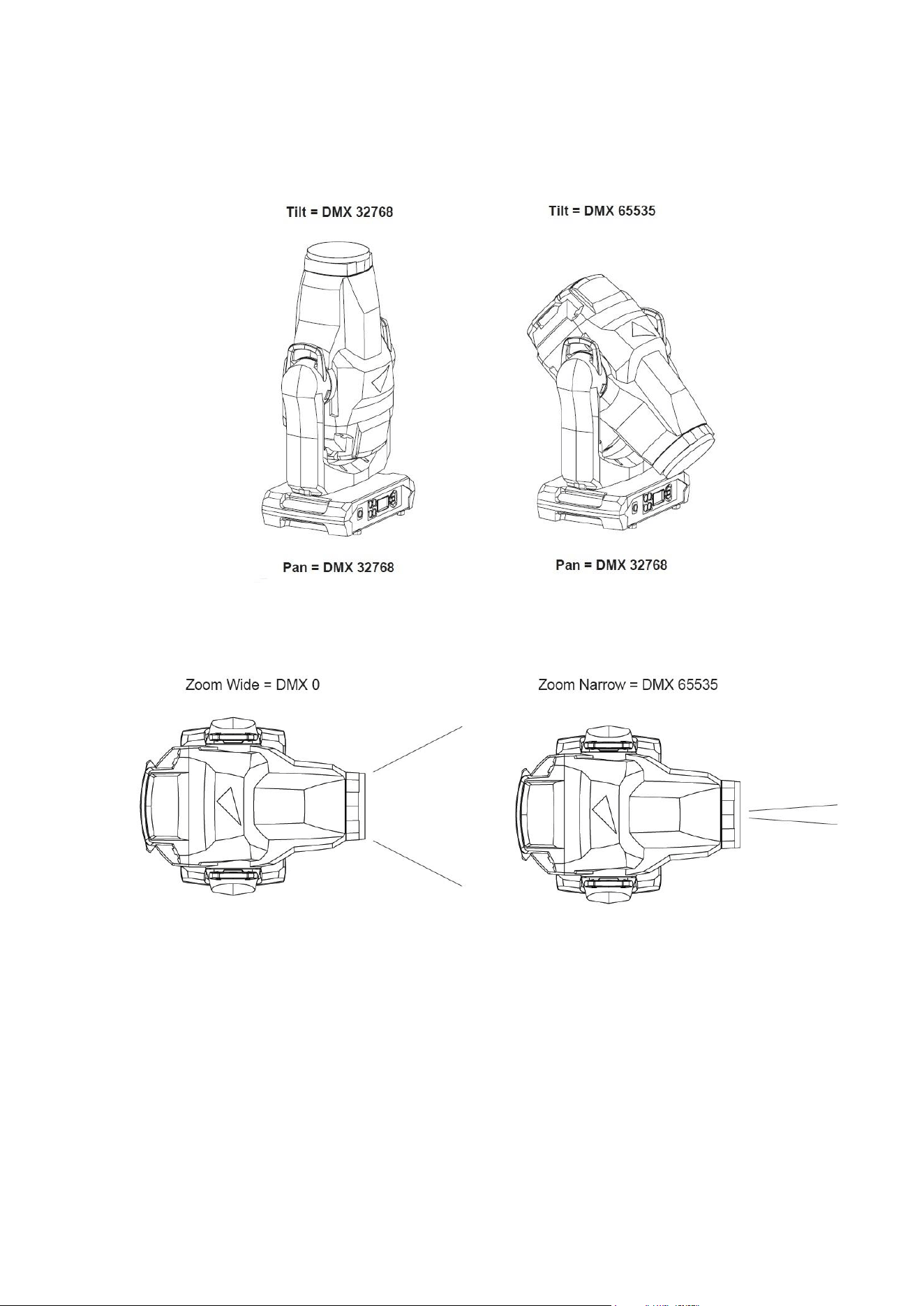
Martin
®
MAC Viper XIP User Manual Revision E 71
Fixture shown in illustrations is for example purposes only

72 Martin
®
MAC Viper XIP User Manual Revision E
Service messages
The MAC Viper XIP gives service and maintenance information by displaying a large 3- or 4-character
short code and a smaller full-text message in the fixture’s display. The short code is visible at a
distance, allowing easier reading with the fixture still in the rig, for example, while the full-text message
gives more detailed information.
Excessively high temperatures
If any of the temperature sensors reports that the fixture has exceeded its recommended temperature
range, the fixture reports a temperature warning and reduces light output to reduce its temperature. If
the temperature reaches a dangerous level, light output is shut down completely.
Temperature warnings are canceled and full light output becomes available again as soon as the
temperature returns to normal.
Warning messages
Warning messages indicate that either:
• problems might appear in the future if no action is taken, or
• the user needs to pay special attention to a function or procedure when working with the fixture.
The fixture communicates warnings as follows:
• Warning codes are shown continuously in the display and disappear when the user reacts to the
warning.
• If more than one warning is detected, all warnings are displayed in sequence.
• If the display is inactive, the fixture’s status LED flashes amber to indicate that there is a warning.
Activating the display will show the warning.
The possible warning messages are listed below:
Short code
Long message and explanation
BANK
BANK NO ACCESS
Error unpacking firmware bank during/after software upload. Fixture will continue to
operate on existing firmware. Warning message is cleared by a successful software
upload or at the next power off/on cycle.
BATM
BATTERY MODE
Fixture in battery mode. Certain control menu items are not available.
BETW
BEAM TMP HIGH
LED beam pixels sensor detects abnormally high operating temperature.*
CMTW
CMY TEMP HIGH
CMY module sensor detects abnormally high operating temperature.*
CTUP
CONNECTORS UPWARD
Fixture oriented with connections panel facing upwards.
DRYO
DRYING
Drying out function active.
DRYR
DRY OUT FUNC RECOM
Drying out function recommended.
EFTW
EFF TEMP HIGH
Effects module sensor detects abnormally high operating temperature.*
F2TW
FRAMING2 TMP HIGH
Framing module sensor 2 detects abnormally high operating temperature.*

Martin
®
MAC Viper XIP User Manual Revision E 73
FRTW
FRAMING TMP HIGH
Framing module sensor 1 detects abnormally high operating temperature.*
FTNA
FROST ADJUST
Frost effect out of adjustment range.
G11M
GOBO 1-1 MISSING
Gobo Wheel 1: Gobo 1 not detected.
G12M
…
G17M
GOBO 1-2 … GOBO 1-7 MISSING
Gobo Wheel 1: Gobo 1 … 7 not detected.
G21M
GOBO 2-1 MISSING
Gobo Wheel 2: Gobo 1 not detected.
G22M
…
G27M
GOBO 2-2 … GOBO 2-7 MISSING
Gobo Wheel 2: Gobo 1 … Gobo 7 not detected.
LDTW
LED DRV TMP HIGH
LED Driver PCB sensor detects abnormally high operating temperature.*
LETW
LED BOARD TEMP HIGH
LED PCB sensor detects abnormally high operating temperature.*
NFCW
NFC WARNING
NFC system unable to access data.
PARK
SAFE PARKING
Fixture is in Safe Parking mode.
PNTW
PAN TEMP HIGH
Pan motor sensor detects abnormally high operating temperature.*
PUTW
PSU TEMP HIGH
PSU sensor detects abnormally high operating temperature.*
SERV
SERVICE MODE
Fixture in service mode.
TLTW
TILT TEMP HIGH
Tilt motor sensor detects abnormally high operating temperature.*
UITW
UI TEMP HIGH
User interface (LCD display and control panel) PCB sensor detects abnormally high
operating temperature.*
ZFTW
ZF TEMP HIGH
Zoom/focus PCB sensor detects abnormally high operating temperature.*
*High temperature warnings are canceled as soon as temperature returns to normal. If temperature
reaches cutoff level, the warning is replaced by a cutoff error message.

74 Martin
®
MAC Viper XIP User Manual Revision E
Error messages
Error messages indicate that a problem is present. The fixture communicates errors as follows:
• Error messages flash in the display.
• If more than one error is detected, the fixture flashes all errors three times each.
• Errors are shown in the display regardless of display status: they override an inactive display and
any other information that the display might be showing.
• If an error is present, the status LED flashes red.
The possible error messages are listed below:
Short code
Long message and explanation
APER
AW POS ERROR
Animation Wheel position error.
ARER
AW ROT ERROR
Animation Wheel rotation error.
C1ER
COLORWHEEL 1 ERR
Color Wheel error.
CECM
COM ERR CMY
CMY module communication error.
CEEF
COM ERR EFFECT
Effects module communication error.
CELD
COLOR ENGINE ERR LED DRV
LED driver communication error.
CEPT
COM ERR PAN TILT
Pan/tilt system communication error.
CEZF
COM ERR Z/F
Zoom/focus effect communication error.
CMTC
CMY TEMP CUTOFF
CMY module temperature cutoff activated.
CMTE
CMY TEMP SEN ERR
CMY module temperature sensor error.
COLD
FIXTURE COLD
Fixture too cold. Physical movement of effects is disabled until fixture has warmed up.
CTER
CTC ERROR
CTC flag position error.
CYER
CYAN ERROR
Cyan flag position error.
EFTC
EFF TEMP CUTOFF
Effects module temperature cutoff activated.
EFTE
EFF TEMP SEN ERR
Effects module temperature sensor error.
F2TC
FROST TEMP CUTOFF
Frost effect temperature cutoff activated.
F2TE
FROST TEMP SEN ERR
Frost effect temperature sensor error.

Martin
®
MAC Viper XIP User Manual Revision E 75
FAN
BASE FAN 1 ERR
FAN
BASE FAN 2 ERR
FAN
BASE FAN 3 ERR
FAN
BASE FAN 4 ERR
FAN
HEAD FAN 1 ERR
FAN
HEAD FAN 2 ERR
FAN
HEAD FAN 3 ERR
FAN
HEAD FAN 4 ERR
FAN
HEAD FAN 5 ERR
FAN
HEAD FAN 6 ERR
FAN
HEAD FAN 7 ERR
FAN
HEAD FAN 8 ERR
FAN
HEAD FAN 9 ERR
FAN
HEAD FAN 10 ERR
FAN
HEAD FAN 11 ERR
FBEP
PAN FBACK ERR
Pan position magnetic indexing system timeout. Fixture is unable to correct pan
position (but pan movement will often still be possible).
FBET
TILT FBACK ERR
Tilt position magnetic indexing system timeout. Fixture is unable to correct tilt position
(but tilt movement will often still be possible).
FBEZ
ZOOM FBACK ERR
Zoom effect position magnetic indexing system timeout. Fixture is unable to correct
zoom position (but zoom effect will often still be useable).
FOER
FOCUS ERROR
Focus position error.
FRCE
FRAMING COM ERROR
Framing module communication error.
FRTC
FR TEMP CUTOFF
Framing module temperature cutoff activated.
FRTE
FR TEMP SEN ERR
Framing module temperature sensor error.
FSER
FRAMING1 INS ERR
Framing blade 1 insertion position error.
FSER
FRAMING1 ANG ERR
Framing blade 1 angle position error.
FSER
FRAMING2 INS ERR
Framing blade 2 insertion position error.
FSER
FRAMING2 ANG ERR
Framing blade 2 angle position error.
FSER
FRAMING3 INS ERR
Framing blade 3 insertion position error.

76 Martin
®
MAC Viper XIP User Manual Revision E
FSER
FRAMING3 ANG ERR
Framing blade 3 angle position error.
FSER
FRAMING4 INS ERR
Framing blade 4 insertion position error.
FSER
FRAMING4 ANG ERR
Framing blade 4 angle position error.
FW
SERVICE MODE
Fixture in Service Mode.
G1ER
GOBO W 1 ERR
Gobo Wheel 1 position error.
G2ER
GOBO W 2 ERR
Gobo Wheel 2 position error.
HFER
HEAVY FROST ERROR
Heavy frost effect position error.
IRER
IRIS ERROR
Iris effect position error.
LDTC
LED TEMP CUTOFF
LED temperature cutoff activated.
LDTE
LED TEMP SEN ERR
LED temperature sensor error.
LETC
LED BOARD TMP CUTOFF
LED PCB temperature sensor cutoff activated.
LETE
LED BOARD SEN ERR
LED PCB temperature sensor error.
LFER
LIGHT FROST ERR
Light frost effect position error.
MAER
MAGENTA ERR
Magenta flag position error.
MMER
MISSING MODULE ERR
Impossible to communicate with a module that should be present. Module missing or
not correctly connected.
NFCE
NFC ERROR
NFC communication not working.
PAER
PAN ERROR
Pan position electrical indexing system timeout.
PRIE
PRISM INS ERR
Prism insertion position error.
PRRO
PRISM ROT ERR
Prism rotation error.
PSER
PAN SENSOR ERROR
Fixture unable to retrieve reliable data from pan position sensor.
PTCM
P/T SENSOR ADJUST
Pan/tilt sensors are incorrectly adjusted.

Martin
®
MAC Viper XIP User Manual Revision E 77
PTTC
PAN TILT TEMP CUTOFF
Pan/tilt PCB temperature cutoff activated.
PTTE
PAN TILT TEMP ERROR
Pan/tilt PCB temperature sensor error.
PRRO
PRISM ROT ERR
Prism rotation error.
PUTC
PSU TEMP CUTOFF
PSU temperature cutoff activated.
PUTE
PSU TEMP SEN ERR
PSU temperature sensor error.
R1ER
GOBO W 1 ROT ERR
Gobo Wheel 1 rotation error.
R2ER
GOBO W 2 ROT ERR
Gobo Wheel 2 rotation error.
SEER
ARTNET SOURCES EXCEEDED / ETH SOURCES EXCEEDED / SACN SOURCES
EXCEEDED
Number of Art-Net / Ethernet protocol / sACN control sources exceeded.
SRNM
SERIAL NUMBER MISMATCH
One of the modules originally installed and calibrated in the fixture has been replaced
with a module from another fixture.
TIER
TILT ERROR
Tilt position electrical indexing circuit timeout.
TSER
TILT SENSOR ERR
Fixture unable to retrieve reliable data from tilt position sensor.
UITC
UI PCB TEMP CUTOFF
User interface module temperature cutoff activated.
UITC
UI TEMP CUTOFF
User interface (LCD display and control panel) temperature cutoff activated.
UITE
UI TEMP SEN ERR
User interface (LCD display and control panel) temperature sensor error.
WEER
WASH EFFECT ERROR
Wash effect position error.
YEER
YELLOW ERROR
Yellow flag position error.
ZFTC
ZF TEMP CUTOFF
Zoom/focus module temperature cutoff activated.
ZFTE
ZF TEMP SEN ERR
Zoom/focus module temperature sensor error.
ZOER
ZOOM ERROR
Zoom position error.
ZSER
ZOOM SENSOR ERROR
Zoom position sensor error.

78 Martin
®
MAC Viper XIP User Manual Revision E
Accessories and service procedures
This section gives instructions for service procedures that may be carried out by the user. For any
procedure that is not described below or in the MAC Viper XIP Safety and Installation Manual, please
contact your Martin supplier for assistance.
Before carrying out service on the fixture, read the ‘Safety Information’ section of the fixture’s Safety
and Installation Manual that is included at the end of this User Guide, supplied with the fixture and
available for download from the Martin website at www.martin.com. Do not remove any cover from the
fixture unless the fixture is in a dry location under dry conditions.
Uploading new firmware
Important! Do not switch the fixture off or disconnect the source of the firmware during an update, or
the firmware will be corrupted.
Fixture information and settings are not affected when you upload new firmware to the fixture.
All MAC Viper XIP fixtures that are powered on and connected via a DMX link to the fixture that you
update will also have their firmware updated.
If you update firmware to a newer version, check the MAC Viper XIP area of www.martin.com to see
whether an updated version of the fixture’s User Manual is available for the new firmware.
You can check the currently installed firmware version in the INFORMATION menu in the fixture’s
control panel. Firmware updates can be downloaded automatically from the Martin cloud using the
Martin Companion software suite on a PC connected to the Internet.
You can update the fixture’s firmware using one of the following methods:
• A USB memory device inserted into the USB port beside the fixture’s control panel.
• A Windows PC running the Martin Companion application with a Martin Companion Cable
USB/DMX hardware interface connected either to the fixture’s DMX IN socket or to the DMX
link.
• A Martin P3 System Controller or Windows PC running the Martin P3-PC application,
connected to the fixture(s) via network cables. See the P3 System Controller user manual for
more information.
Installing using a USB memory device
The following are required in order to install firmware using a USB flash drive:
• The MAC Viper XIP ‘.BANK’ firmware update file, which the Martin Companion application will
download automatically when you run Martin Companion on a PC with an Internet connection.
• A USB flash drive with the firmware update file copied from a PC into the USB flash drive’s root
directory.
To install the MAC Viper XIP firmware:
1. Download the ‘.BANK’ firmware file from the Martin cloud within the Martin Companion Application
and press Download USB Stick Firmware...
2. Read the firmware release notes carefully to check for any instructions or warnings, and copy the
firmware file to the root directory of the USB flash drive.
3. Disconnect the DMX data link from the MAC Viper XIP.
4. Insert the USB flash drive into the MAC Viper XIP’s USB host socket. The fixture should recognize
the USB flash drive and illuminate the display. If the fixture does not recognize the USB flash drive,
navigate to SERVICE → USB in the fixture’s control panel.
5. AVAILABLE FIRMWARE will appear in the display. You can now scroll through the firmware
versions available.

Martin
®
MAC Viper XIP User Manual Revision E 79
6. To install a firmware version, select it and press ENTER. The MAC Viper XIP asks you to confirm
installation of the new firmware. Press ENTER to confirm and press MENU to exit without
confirming.
7. Allow the fixture to install the firmware and reboot. Do not remove the USB flash drive until the
fixture has successfully rebooted.
8. Remove the USB flash drive. The newly-installed firmware version will now be displayed in the
INFORMATION menu.
9. Reconnect the data link.
Installing using a PC and Martin Companion
The following are required in order to install firmware using a PC:
• A Windows PC running the latest version of the Martin Companion software suite (available for
download free of charge from the Martin website at www.martin.com).
• The MAC Viper XIP firmware file, which the Martin Companion application will download
automatically when you run Martin Companion on a PC with an Internet connection.
• The Martin Companion Cable USB-DMX hardware interface, available from your Martin
supplier by ordering P/N 91616091.
To install the MAC Viper XIP firmware using a PC and Martin Companion:
1. Apply power to the MAC Viper XIP fixture(s) and allow it to boot.
2. Connect the Martin Companion Cable’s USB connector to a USB port on your PC. Connect the
Martin Companion Cable’s XLR connector either directly to the fixture’s DMX IN connector or to the
DMX link.
3. Start the PC and launch the Martin Companion application. Check that Martin Companion correctly
detects the Martin Companion Cable (a green dot should appear next to USB Connected in the
top right-hand corner of the window).
4. Locate the latest MAC Viper XIP firmware in Martin Companion’s Firmware window.
5. Start the firmware update by clicking Update Firmware in Martin Companion. Do not disconnect
the Martin Companion Cable or power off the fixture(s) until the upload is complete and the
fixture(s) has successfully rebooted.
6. If you are updating multiple fixtures over a DMX link, check that they have all rebooted correctly.
Fixture-to-fixture firmware uploads
It is possible to update the firmware in one fixture (using a USB flash memory flash memory device, for
example), and then use that fixture to carry out a fixture-to-fixture firmware upload. This method will
install the new firmware in all the other fixtures that are powered on and connected to the same DMX /
RDM / Art-Net data link. You must use the control panel of the fixture with the new firmware to send the
firmware out to the other fixtures on the data link. The other fixtures will automatically recognize that
firmware is being sent to them and accept the firmware update. Only MAC Viper XIP fixtures will accept
the new firmware – other types of fixture will ignore it.
To carry out a fixture-to-fixture upload:
1. Apply power to the fixture that has the new firmware, apply power to the fixtures that you want to
send the firmware to, and wait for all the fixtures to reset. Disconnect any DMX, Art-Net, sACN or
P3 controllers from the data link.
2. In the fixture that has the new firmware, open the SERVICE menu and go to FIXTURE TO
FIXTURE FW. Select from UPLOAD VIA DMX512 or UPLOAD VIA ART-NET, depending on the
type of data link used, and select START. The firmware will be uploaded to the other fixtures on
the data link using RDM protocol.
Note that fixtures on an Art-Net link must be in the same DMX universe.
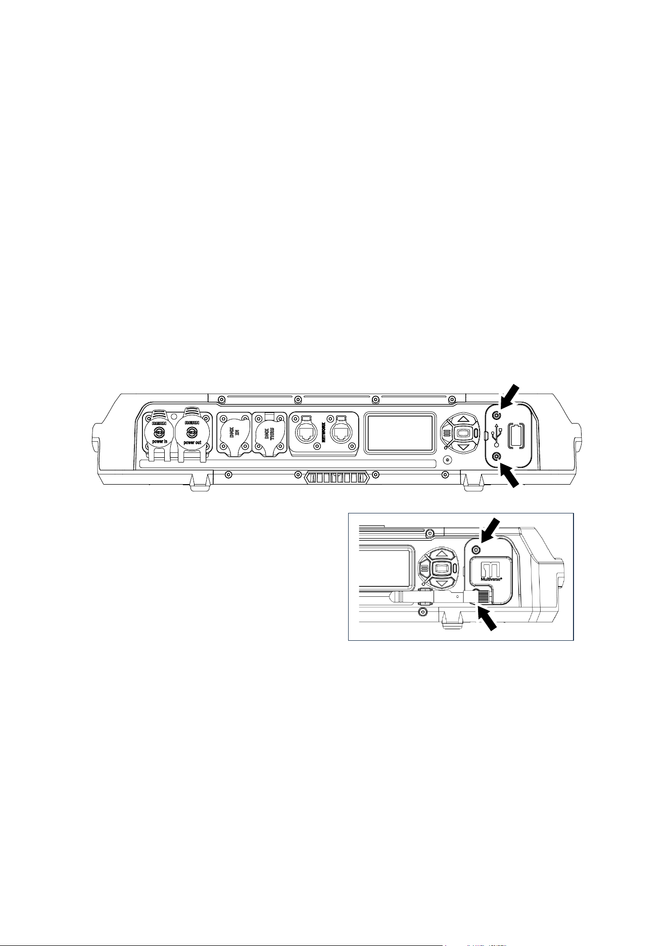
80 Martin
®
MAC Viper XIP User Manual Revision E
The FORCE command forces all connected fixtures to accept the new firmware, even if they
already have that firmware version installed (if fixtures already have a firmware version installed,
they will normally ignore uploads of that same firmware version).
You can select from two firmware transfer speeds: HIGH SPEED and HIGH STABILITY. If you
encounter problems that may be caused by interference, imperfect data connectivity, external
noise, etc. while you are trying to upload firmware, select HIGH STABILITY. This sends each data
packet twice and may resolve stability issues.
3. When the firmware upload is complete, the fixtures that have received firmware will reboot on the
new firmware.
Installing a Universal Connect Module
Universal Connect Modules available from various manufacturers can be installed on the MAC Viper
XIP. The module mounts onto the fixture’s connections/control panel in place of the battery/USB port
cover.
To install a Universal Connect Module:
1. See illustration below. Remove the two screws (arrowed) from the plastic battery/USB port cover
and lever the cover gently away from the connections/control panel with a plastic lever (or flat-
headed screwdriver). This cover mates with the fixture’s USB port with a rubber seal, so there will
be some resistance when you lever the cover off. Do not remove the yellow rubber battery cover
that becomes visible when you remove the plastic battery/USB port cover.
2. See illustration on right. Line up the USB-C
connector on the back of the Universal Connect
Module with the fixture’s USB port. Make sure
that you feel the USB plug reaching the USB
header, then push the module into position on
the connections/control panel so that the USB
connector mates with the USB port in the fixture.
Reinstall the two screws (arrowed) from the
original cover. You will probably need to
unscrew the antenna temporarily for easy
access to the lower of the two screws.
To keep the battery cover in a safe and convenient place, it is possible to fit the cover into one of the
head air filter compartments:
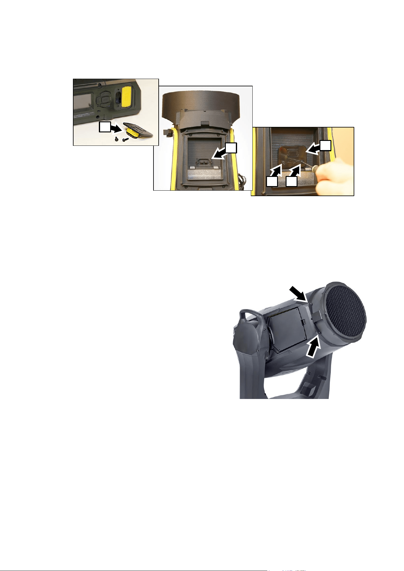
Martin
®
MAC Viper XIP User Manual Revision E 81
1. Remove the head air filter cover and head air filter on the tilt lock side of the fixture’s head
following the instructions in the ‘Service and Maintenance’ chapter of the fixture’s Safety and
Installation Manual included at the end of this User Manual.
2. See photos above. Fit the battery cover into the space provided behind the air filter, pushing the
yellow seal A into the recess B with the main body of the battery cover C pointing upwards,
towards the front of the head.
3. Fasten the battery cover into its storage space using the two screws D provided in the storage
space.
4. Reinstall the air filter and air filter cover as described in the Safety and Installation Manual.
Installing a Hexcel Louver
A Hexcel Louver for the MAC Viper XIP is available
from City Theatrical, Part Number 2817. See details at
www.citytheatrical.com.
See illustration on right. The Hexcel Louver mounts
onto the head using the four screws provided on the
front of the head, two screws (arrowed), on each side.
A
C
D
D
B
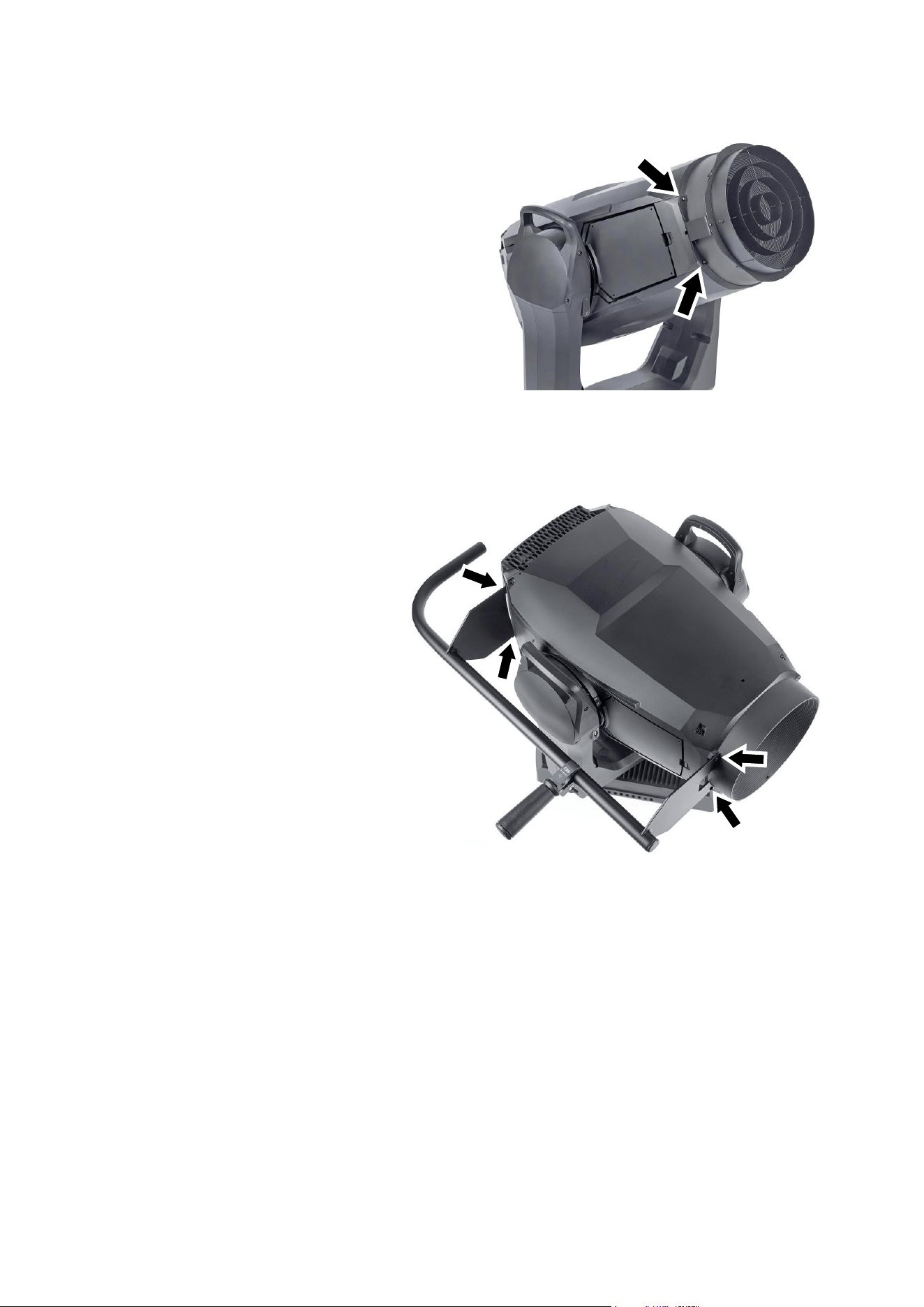
82 Martin
®
MAC Viper XIP User Manual Revision E
Installing a Concentric Ring louver
A Concentric Ring Louver for the MAC Viper XIP is
available from City Theatrical, Part Number 2816. See
details at www.citytheatrical.com.
See illustration on right. The Concentric Ring Louver
mounts onto the front of the head using the four
screws (arrowed), two screws on each side of the
head.
Installing a Followspot Handle
A Followspot Handle for the MAC Viper
XIP is available from City Theatrical,
Part Number 2815. See details at
www.citytheatrical.com.
See illustration on right. The Followspot
Handle mounts onto the head of the
fixture using the four screws (arrowed) in
the front and back of the head. You can
mount the Followspot Handle on either
side of the head.
Set the fixture to Followspot Mode in the
control menus, via RDM, on the
Control/Settings DMX channel or via P3
when using the Followspot Handle.
• FOLLOWSPOT MODE disables
DMX control of pan and tilt,
releasing the head for manual
aiming.
• The TOGGLE HOLD command in
the fixture’s control panel shortcut menu holds the head stationary or releases it.
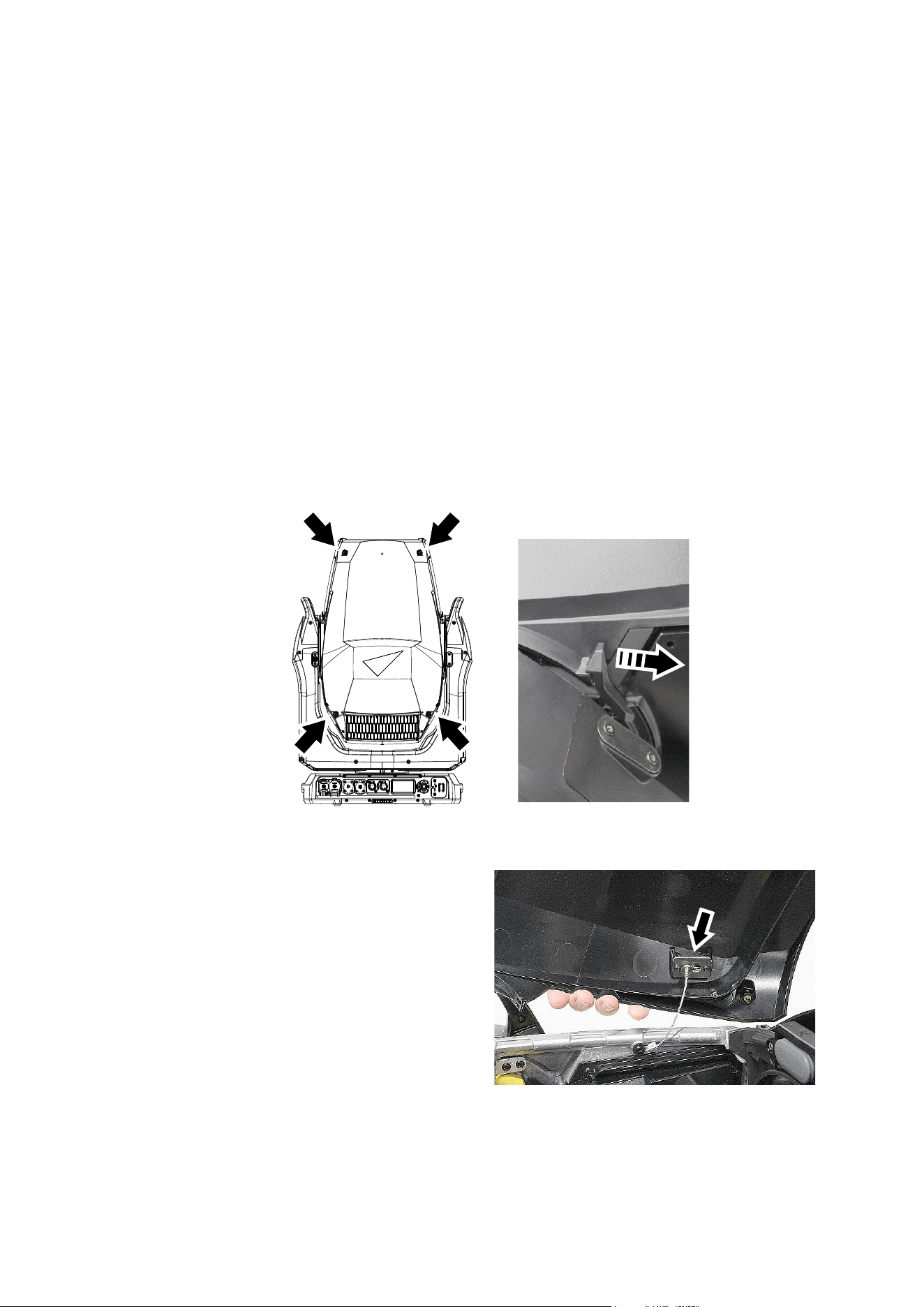
Martin
®
MAC Viper XIP User Manual Revision E 83
Removing the top head cover
Seal care
The fixture’s yellow rubber seals, particularly in the head, can become sticky over time. This can make
covers difficult to remove, and you can risk displacing or deforming seals during cover removal. To
make service easier and protect the seals, apply a very thin film of silicone grease to them when
servicing the head. Apply just enough grease to act as a release agent. Wipe off any excess grease.
When the grease is correctly applied it should hardly be visible.
Cover removal
To remove the top head cover:
1. Disconnect the fixture from power and allow it to cool for 20 minutes.
2. Place the fixture on a stable work surface, tilt the head so that the Martin logo is facing the correct
way up – in this position the top head cover faces upwards – and apply the tilt lock.
3. See illustration below. Release the four captive screws (arrowed) in the top head cover. On each
side of the head, push the head cover release latch towards the front of the head and lift the head
cover up slightly to release it. It is possible to release the head cover from the latches one side at a
time, but do not apply excessive force to the head cover.
4. When you have released the head cover on
both sides of the head, lift the head cover up
completely and either disconnect the head
cover safety wire (see illustration on right) or
leave the head cover hanging on the safety
wire.
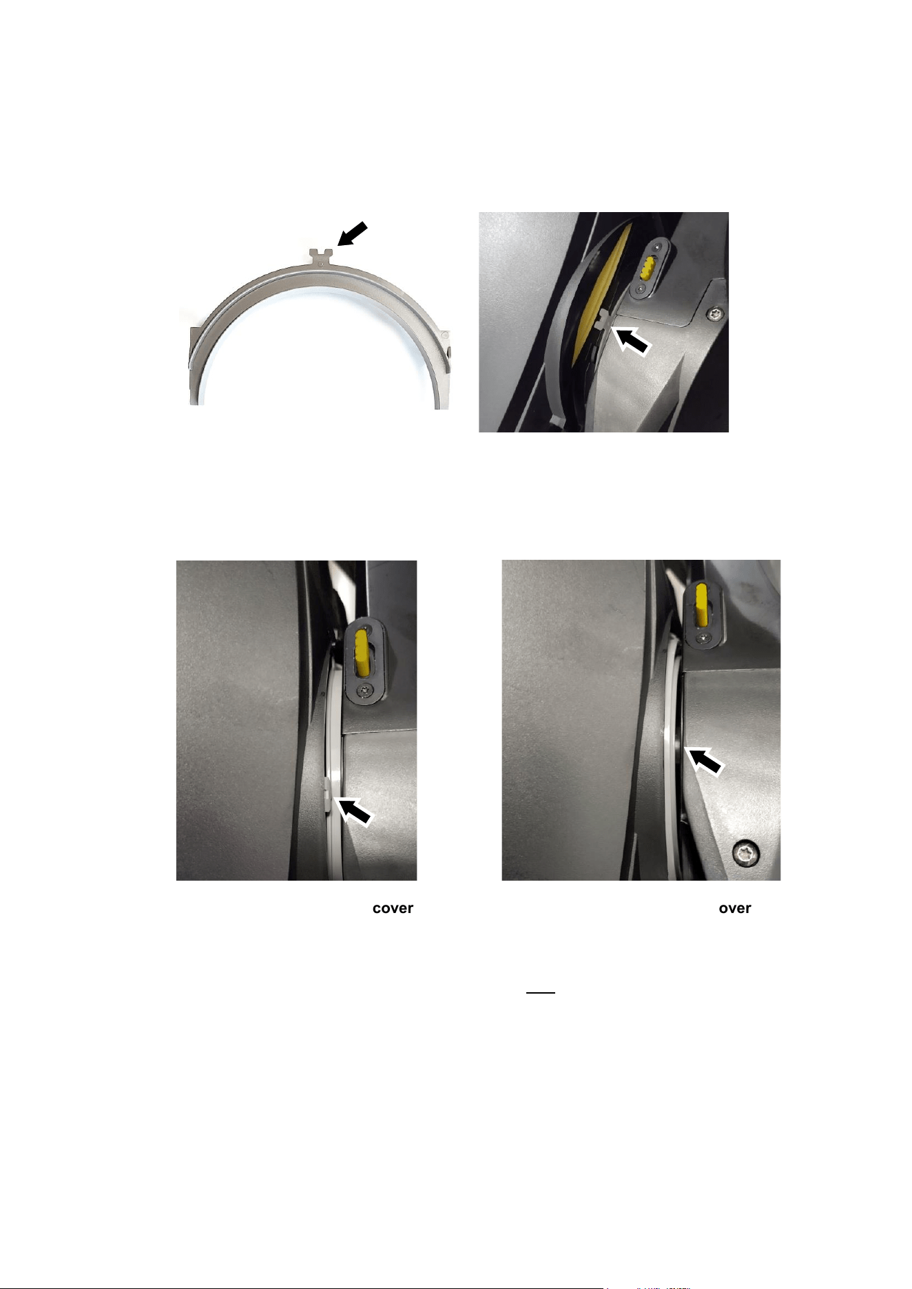
84 Martin
®
MAC Viper XIP User Manual Revision E
Reinstalling the head cover
To reinstall the head cover:
1. Make sure that the safety wire is securely attached using its push-and-slide lock (see illustration on
previous page).
2. See illustration above. A tilt insert sits around the tilt pivot on each side of the yoke. The tilt inserts
only need to be removed when removing the yoke cover – you should leave them in position when
removing and reinstalling head covers. However, you must make sure that the tabs (arrowed) in
the inserts on both sides of the yoke fit inside the head cover when you reinstall the cover as
shown in the illustration below.
3. The rubber seals in the head can become sticky over time, making covers difficult to remove and
making it possible to deform or misplace the seal. Apply a very thin layer of silicone grease to the
rubber seals to act as a release agent for the next time a head cover is removed.
4. Place the head cover onto the head, checking that the tabs in the tilt inserts fit inside the head
cover. Make sure that the head cover release latches (see illustration on previous page) click
towards the back of the head to hold the head cover in place.
5. Reinstall the four head cover screws. Important! Do not overtighten the head cover screws –
apply a maximum torque of 1.5 Nm.
6. Check that the head cover is secure, with no gaps visible around any part of the cover.
Incorrect – tab outside head cover
Correct – tab inside head cover
✓
X

Martin
®
MAC Viper XIP User Manual Revision E 85
7. Release the tilt lock before operating the fixture.
Internal effect module calibration
The MAC Viper XIP is calibrated at the factory when its effects modules are installed. We therefore
recommend that you keep the original modules with the fixture if you disassemble the fixture for
service. If you swap modules from one fixture to another, the fixtures may need to be recalibrated if it is
important for you to maintain consistent color characteristics across different fixtures.
Replacing rotating gobos
The MAC Viper XIP uses specially designed borosilicate 3.3 rotating gobos. The gobos are a custom
size. Their external diameter is 27.1 mm +0/-0.2 mm (1.067 in. +0/-0.008 in.), and the image diameter
is 22 mm (0.866 in.). The gobo thickness is 1.1 mm +/- 0.1 mm (0.04 in. +/- 0.004 in.). The gobos are
manufactured in Borofloat 33 glass with a heavy matted aluminum coating.
Although the goboholders on Gobo Wheel 1 are different from the goboholders on Gobo Wheel 2, the
actual gobos are the same type and size and can be interchanged no matter which wheel they are
installed on.
Replacement gobos must have the same dimensions, construction, materials and quality as the gobos
supplied as standard. Using gobos that do not meet this requirement – such as metal gobos – will very
probably cause damage that is not covered by the product warranty.
Optical components have fragile coatings and are exposed to very high temperatures. Handle and
store components with care.
See ‘Rotating gobos’ on page 11 for names, illustrations and part numbers of the gobos installed as
standard.
Avoiding damage to gobos
Follow these precautions when handling, using and storing gobos:
• Do not use gobos with dark coatings on either side, as these will absorb heat – either directly from
the light source or reflected back from other optical components – and will not be durable.
• Do not use metal gobos in the MAC Viper XIP: their durability may be reduced when used in this
fixture.
• Store all gobos in a dust-free environment with approx. 50% humidity.
• Wear clean nitrile cleanroom gloves when handling gobos.
• Avoid scratching coated and uncoated sides.
• Do not place a gobo with the coated side face-down on any surface.
• Avoid touching the other gobos when removing a gobo from a rack: the sharp edge of one gobo
can scratch the others.
• Keep gobos perfectly clean to reduce the risk of heat damage.
• When cleaning gobos, use a repeated dabbing action rather than a rubbing action. When rinsing,
use distilled or even better deionized water to avoid residue that will appear as drying marks.
• If possible, clean the coated side of gobos with dust and oil-free compressed air only. If the coated
side is contaminated with oil, clean with isopropyl alcohol and optics cleaning tissues.
• Clean the uncoated side of gobos with isopropyl alcohol or photographic quality lens-cleaner and
optics cleaning tissues.
• Do not try to clean gobos in an ultrasound bath, as this may cause delamination of the coating.
• Do not use acidic or alkaline cleaning solutions, as they will attack the aluminum coating.
• Correct gobo orientation is critical. Read the guidelines given in this chapter carefully before
installing a gobo.
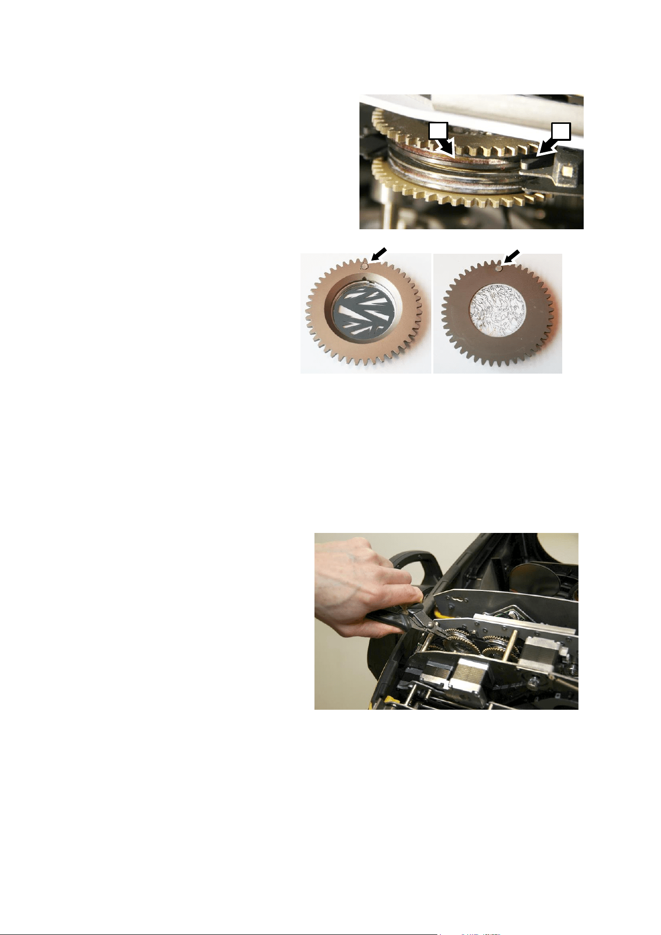
86 Martin
®
MAC Viper XIP User Manual Revision E
Goboholder clips
See photo on right. Goboholders in the MAC Viper XIP
have grooves A around their edges that are held in
clips B in the gobo wheel.
Goboholder reference marks
See photos on right. The goboholders in
the MAC Viper XIP have magnets
(arrowed) that you can use as reference
points.
Gobo replacement procedure
We recommend that you replace goboholders one at a time. This makes it easier to orient the
goboholders correctly in the wheel.
To replace a rotating gobo:
1. Remove the top head cover as described earlier in this chapter.
2. Release the tilt lock, tilt the head to a convenient angle for access to the gobo wheels and reapply
the tilt lock.
3. Gobo wheel 1 is closest to the LED light source, Gobo wheel 2 is closest to the front lens. Rotate
the gobo wheel until the gobo that you
want to replace is easily accessible.
4. Without rotating the gobo wheel, place
your thumb on the teeth of the goboholder
and rotate the goboholder until the
magnet is pointing directly away from the
center of the gobo wheel. This gives you a
reference. You will need to reinstall a
goboholder with the magnet in exactly this
position.
5. See photo on right. Using a pair of flat-
nosed pliers, grasp the teeth of the
goboholder firmly and pull the goboholder
out of its clip in the gobo wheel.
For instructions on how to install a new gobo in a goboholder, see later in this section.
To reinstall a goboholder in the gobo wheel:
1. Rotate the goboholders in the wheel so that the magnets are pointing directly away from the center
of the gobo wheel.
2. Line up the goboholder that you are installing with its magnet also pointing directly away from the
center of the gobo wheel.
B
A
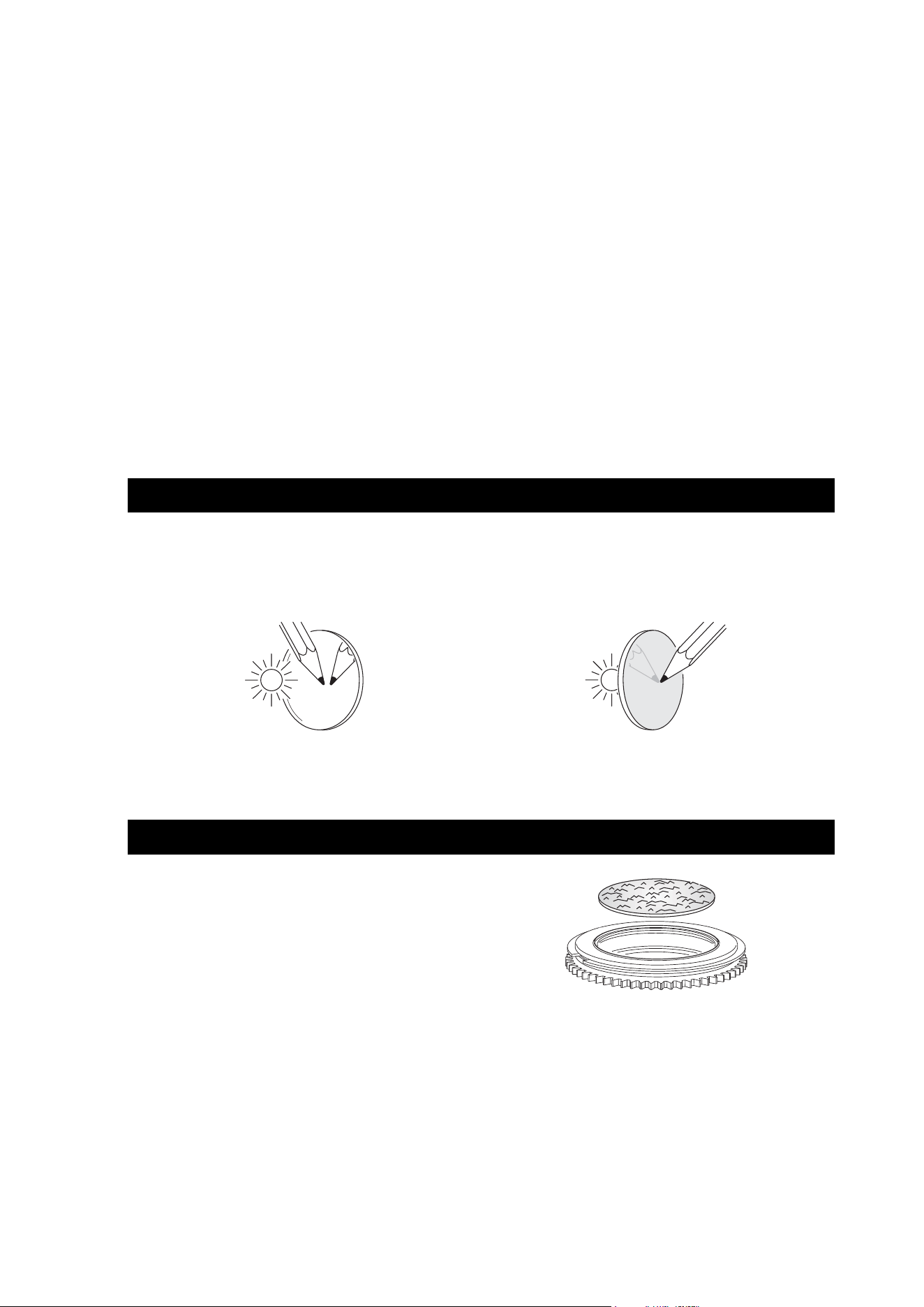
Martin
®
MAC Viper XIP User Manual Revision E 87
3. Bend the thin metal plate on the gobo wheel away from the wheel very slightly so that you have
room to slide the goboholder back into its clip in the gobo wheel.
4. Holding the goboholder teeth with flat-nosed pliers, slide the goboholder back into the jaws of its
clip.
5. Check that the gobo is pushed fully into its clip and held securely. To check that the goboholder is
correctly installed, rotate the goboholder at least 180° in both directions in the gobo wheel and
check that it and all the other goboholders move freely.
Replacing a gobo in a goboholder
The rotating gobos in the MAC Viper XIP are held in their holders by springs and can be removed from
their holders as described in this section.
Gobo orientation: general
Make sure that you install gobos facing in the correct direction, or they may suffer heat damage. The
orientations shown below are correct in most cases, but consult your Martin dealer or gobo supplier if
you are in any doubt about the orientation of a specific gobo type.
Coated Glass gobos
The heavy matted aluminum coated borosilicate gobos in the MAC Viper XIP are factory-installed
with the more reflective sides facing towards the LED light source. Replacement gobos must also be
installed with more reflective sides facing the LEDs in order to avoid heat damage.
More reflective side towards LEDs
To minimize the risk of gobo overheating and
damage, turn the more reflective side of a
coated gobo towards the light source.
Less reflective side away from LEDs
The less reflective side of a coated gobo will
absorb less heat if it faces away from the light
source.
Textured Glass gobos
Flat side towards goboholder
If you install a textured glass gobo in the fixture,
note that a textured glass gobo sits most
squarely in a goboholder with the flat side placed
down into the recess in the goboholder. If in
doubt, consult your Martin dealer or gobo
supplier. We recommend that textured glass
gobos are glued into the goboholder.
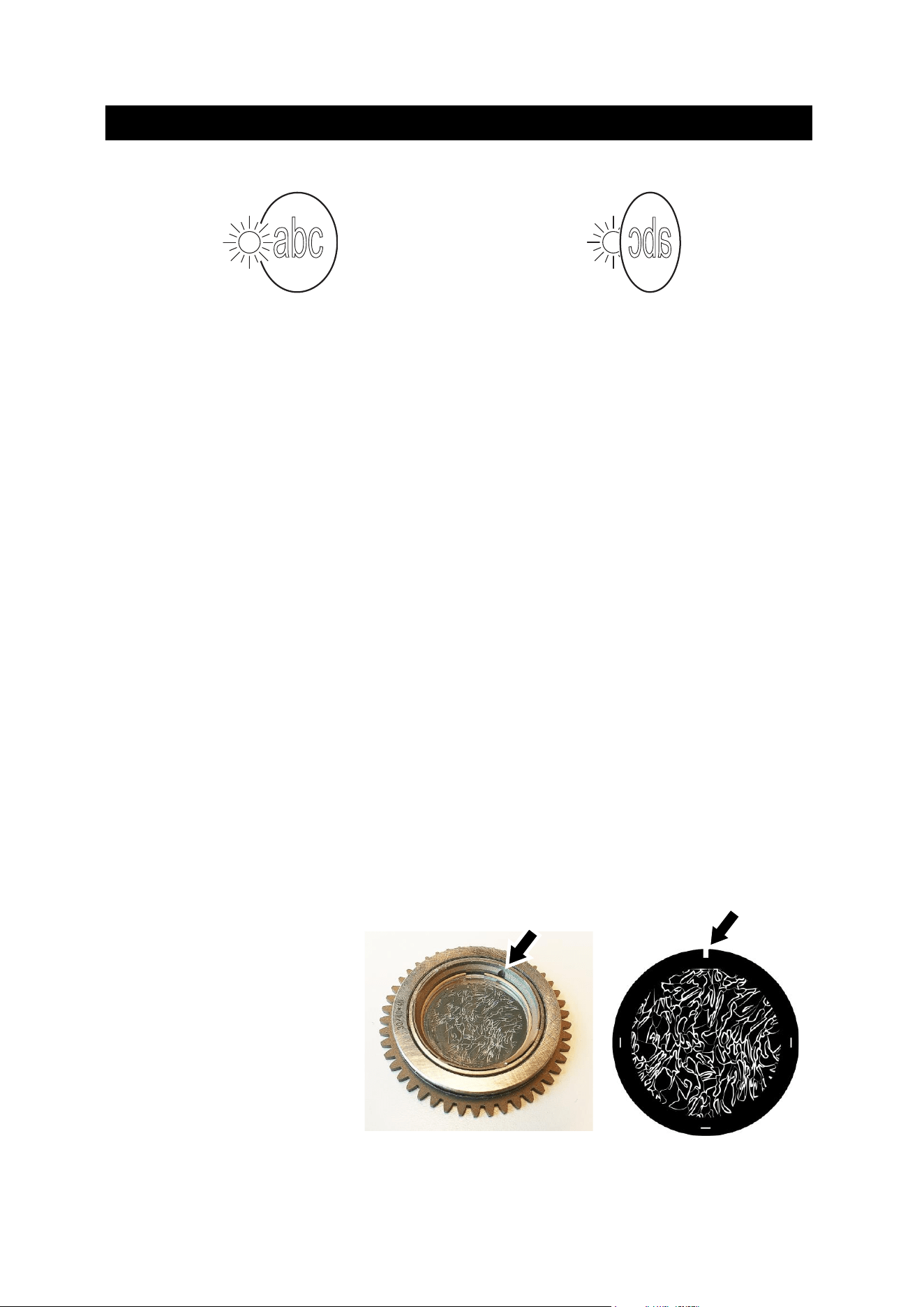
88 Martin
®
MAC Viper XIP User Manual Revision E
Image/text gobos
True image towards LEDs
Reversed image away from LEDs
Gobos that have a specific left/right orientation (such as text gobos) will appear correctly in the
projection if they appear correctly when viewed from the side that faces towards the LED light
source.
Goboholder and gobo orientation, Gobo Wheel 1 (Aerial Wheel)
• Gobo Wheel 1 is the wheel that is closest to the LED light source.
• The side of the goboholder with the gobo retaining spring and with the teeth faces towards the LED
light source.
• The shiny side of the gobo faces towards the spring and towards the teeth in the goboholder so
that it faces towards the LED light source.
• The white, non-reflective side of the gobo faces away from the spring and away from the teeth in
the goboholder so that it faces towards the front lens.
Goboholder and gobo orientation, Gobo Wheel 2 (Breakup Wheel)
• Gobo Wheel 2 is the wheel that is closest to the front lens.
• The side of the goboholder with the gobo retaining spring and without the teeth faces towards the
LED light source.
• The shiny side of the gobo faces towards the spring and away from the teeth in the goboholder so
that it faces towards the LED light source.
• The white, non-reflective side of the gobo faces away from the spring and towards the teeth in the
goboholder so that it faces towards the front lens.
Gobo orientation, Wheels 1 and 2
On both gobo wheels in the MAC Viper XIP:
• Images or text on gobos must appear correctly (i.e. not flipped left to right) when looking at the
goboholder from the side with the spring.
• The textured side of textured glass gobos must always face towards the spring. The flat side of
textured gobos must face downwards so that the gobo sits flat in the goboholder.
Gobo alignment
See illustrations on right. Note the
position of the alignment marks
(arrowed) on goboholders and
gobos. Install gobos with the
alignment marks next to each
other.

Martin
®
MAC Viper XIP User Manual Revision E 89
Replacing a gobo
Avoid getting grease from your fingers or dirt onto gobos. Hold gobos by their edges only. Wear clean
nitrile cleanroom gloves when handling gobos.
To replace a gobo in a goboholder:
1. See photo on right. Place the goboholder on a clean
surface with the recess for the gobo and gobo spring
facing upwards. Note the position of the ends (arrowed)
of the gobo retaining spring. Taking care not to scratch
the gobo, use a flat-bladed screwdriver or similar tool
inserted between the spring and the goboholder (not
between the spring and the gobo), to lever one end of
the retaining spring out of the groove in the goboholder.
Lift the retaining spring out of the goboholder.
2. Turn the goboholder over so that the recess faces
downwards and let the gobo fall out of the holder onto a
clean, soft surface. Turn the goboholder over again and
put it on the surface with the recess facing upwards.
3. Holding the new gobo by its edges, insert it into the goboholder with the alignment marks on gobo
and goboholder correctly lined up. The correct gobo orientation is different for Gobo Wheels 1 and
2. Make sure that you insert the gobo facing the correct way round by referring to the guidelines
earlier in this section.
4. Check that the gobo is seated flat in the holder. See photo at Point 1 above. Insert the retaining
spring into the goboholder in its original position and press it into its groove in the goboholder.
Important! The gap in the spring must be in the position shown in the photo at Point 1. Check that
the spring is pressed as flat as possible against the gobo and that the gobo is held securely in the
goboholder.
5. Reinstall the goboholder in the gobo wheel and reinstall the top head cover following the directions
given earlier in this section.

90 Martin
®
MAC Viper XIP User Manual Revision E
Compliance and specifications
See the Safety and Installation Manual attached to this user manual for details of this product’s
compliance with national and international standards, FCC rules etc.
See the Martin website at www.martin.com for technical specifications for this product.

www.martin.com
MAC Viper XIP
Safety and Installation Manual
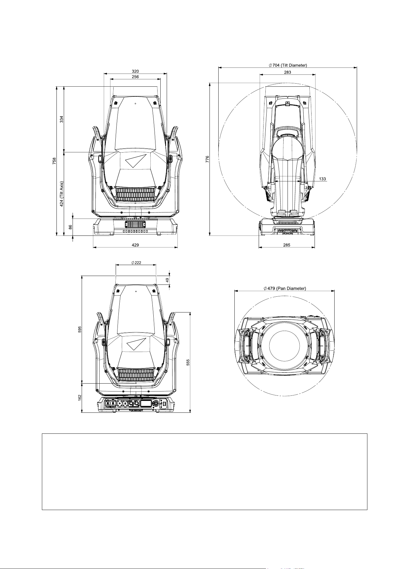
Dimensions
All dimensions are in millimeters
©2024-2025 HARMAN PROFESSIONAL DENMARK ApS. All rights reserved. Features, specifications and appearance are subject
to change without notice. HARMAN PROFESSIONAL DENMARK ApS and all affiliated companies disclaim liability for any injury,
damage, direct or indirect loss, consequential or economic loss or any other loss occasioned by the use of, inability to use or reliance
on the information contained in this document. Martin is a registered trademark of HARMAN PROFESSIONAL DENMARK ApS
registered in the United States and/or other countries.
HARMAN PROFESSIONAL DENMARK ApS, Olof Palmes Allé 44, 8200 Aarhus N, Denmark
HARMAN PROFESSIONAL, INC. 8500 Balboa Blvd., Northridge CA 91325, USA
www.martin.com
MAC Viper XIP Safety and Installation Manual, English, Revision E

Martin
®
MAC Viper Safety and Installation Manual Revision E 3
Table of contents
Dimensions ................................................................................................................. 2
Safety information ....................................................................................................... 4
Introduction ............................................................................................................... 10
Packing and unpacking .................................................................................. 10
Condensation ................................................................................................. 10
Before using the product for the first time ...................................................... 10
Applying mains power .................................................................................... 10
Cold starting ................................................................................................... 11
Overview ................................................................................................................... 11
Tilt lock ........................................................................................................... 11
Physical installation ................................................................................................... 12
Installation location ........................................................................................ 12
Installation environment ................................................................................. 12
Avoiding damage from other light sources ..................................................... 12
Standing the fixture on a flat surface .............................................................. 12
Mounting the fixture on a truss ....................................................................... 13
Securing with a safety cable .......................................................................... 13
AC mains power ........................................................................................................ 15
Linking fixtures to power in a chain at 100-120 V ........................................... 15
Linking fixtures to power in a chain at 200-240 V ........................................... 15
Connecting to power ...................................................................................... 16
Data connections ...................................................................................................... 16
Service and maintenance .......................................................................................... 17
Service mode ................................................................................................. 17
Cleaning ......................................................................................................... 17
Cleaning air filters .......................................................................................... 18
Battery replacement ....................................................................................... 19
Installing a Universal Connect Module Accessory ......................................... 20
Lubrication ..................................................................................................... 20
Seal care ........................................................................................................ 20
4 Martin
®
MAC Viper XIP Safety and Installation Manual Revision E
Safety information
WARNING!
Read the safety precautions in this manual before installing,
powering, operating or servicing this product.
The following symbols are used to identify important safety information on the product and in this manual:
Warning!
Safety hazard.
Risk of severe
injury or death.
Warning!
Hazardous
voltage. Risk
of lethal or
severe electric
shock.
Warning!
Fire hazard.
Warning!
Burn hazard.
Hot surface.
Do not touch.
Warning!
Intense light
emission.
Warning!
See user
documentation.
Warning! This fixture corresponds to Application Group BLH-C according to EN IEC 62471-7
for stage lighting. It is a Risk Group 3 product according to EN 62471 and Risk Group 2
product according to IEC/TR 62778 (see “Protection from eye injury” on page 8 for full
details). Possibly hazardous radiation emitted from this product. May be harmful to the eyes.
Do not stare directly into the light output from the product. Position the product so that
prolonged staring into the product at a distance closer than 56 m (184 ft.) is not expected.
Do not view the light output with optical instruments or any device that may concentrate the
beam.
The MAC Viper XIP lighting fixture presents risks of severe injury or death due to fire and
burn hazards, electric shock and falls if the safety precautions in this manual are not
followed.
You may carry out external cleaning and service as described in the fixture’s user
documentation, following the warnings and instructions provided, but any service operation
not described in this Safety and Installation manual or in the fixture’s User Manual must be
referred to an authorized Martin service technician.
The MAC Viper XIP is for professional use as a stage light only. It is not for household or
general lighting applications. Respect all locally applicable laws, codes and regulations
when installing, powering, operating or servicing the fixture.
Ensure that the installation complies with the provisions of ANSI/ESTA E1.58-2017. This
standard gives important information on the temporary use of stage and studio lighting
equipment outdoors that is supervised by qualified personnel while energized and
inaccessible to the general public in the USA as referred to by NFPA 70 article 520.10.
Touring shows in Canada must obtain a permit from the relevant authority before the first
performance. Respect national and local regulations at all times.
The light source contained in this fixture must be replaced by Martin
®
Service or an
authorized Martin Service partner only.
Install, operate and service Martin products only as directed in their user documentation, or
you may create a safety hazard or cause damage that is not covered by product warranties.
Read this manual before installing, powering, operating or servicing the fixture. Follow the
safety precautions and observe all warnings in this Safety and Installation Manual, in the
fixture’s User Manual, and printed on the fixture.

Martin
®
MAC Viper Safety and Installation Manual Revision E 5
The latest versions of this Safety and Installation Manual and the fixture’s User Manual are
available for download from the MAC Viper XIP area of the Martin website at
www.martin.com. Before you install, operate or service the fixture, check the Martin website
and make sure that you have the latest user documentation for the fixture. Document
revisions are indicated at the bottom of page 2.
Technical Support
If you have questions about how to install or operate the fixture safely, please contact
Harman Professional Technical support:
• For technical support in North America, please contact
HProTechSupportUSA@harman.com
Phone: (844) 776-4899
• For technical support outside North America, please contact your national distributor.
Protection from electric shock
The fixture has an ingress protection rating of IP54 that is applicable in EN/IEC regions
(Europe and other countries). It has a ‘Damp or Wet Locations’ rating that is applicable in
the USA and Canada. Damp locations are considered to be partially protected locations
under stage and event canopies, marquees, tents, roofed open bars and similar locations,
while ‘Wet Locations’ include most outdoor areas without cover or protective shields, or
some indoor areas exposed to water dripping or splashing.
An IP54 and Wet Locations rating means that a fixture can withstand rain, splashing water,
condensation etc. but not high-pressure water jets. The fixture is designed to be used under
any weather conditions, but it must not be exposed to an artificially high volume of water (in
a fountain, waterfall or shower, for example). The most extreme rain ever recorded had a
volume of 400 mm / 16 inches per hour. The fixture is designed to withstand such a
condition. A fountain, waterfall or shower can create a much bigger volume of water (up to
15 000 mm / 50 feet per hour). The fixture is not designed to withstand conditions like these.
Do not immerse the fixture in water.
Shut down power to the fixture immediately if extreme conditions such as flooding arise.
Do not expose the fixture to high-pressure water jets.
The fixture is designed for temporary outdoor installation only. Installing it permanently in an
outdoor location could cause accelerated aging that would potentially affect its IP54 / Wet
Locations rating. This would create a potential safety hazard and a risk of damage. Do not
use the fixture for permanent outdoor lighting.
Do not install the fixture in locations where the air is aggressive to materials (where the air
has a high salt or chlorine content, close to the sea or a swimming pool, for example).
Do not operate the fixture if the ambient temperature (Ta) falls below -10° C (14° F). Do not
operate the fixture in ambient temperatures below 5° C (41° F) if ice is forming on the fixture.
Protect the fixture from snow and ice. Freezing water may deform the fixture’s housing,
creating a safety hazard. Monitor weather conditions and take all appropriate safety
precautions if a freezing hazard is forecast or present.
The fixture is rated IP54 / ‘Wet Locations’ only when the following types of connector are
used on cables connected to the fixture:
• Neutrik powerCON TRUE1 NAC3FX-W-TOP connector at the power IN socket,
• Neutrik powerCON TRUE1 NAC3MX-W-TOP connector at the power THRU socket,
• Neutrik TOP series 5-pin locking XLR connectors at the XLR (DMX, RDM) data sockets,
and
• Neutrik TOP series etherCON connectors at the Ethernet (Art-Net, sACN) data sockets.
Use only these connector types and use only cables that are suitable for the given
application with respect to humidity, water and sunlight resistance.

6 Martin
®
MAC Viper XIP Safety and Installation Manual Revision E
The power and data connectors are fitted with rubber caps to protect from water ingress.
Keep rubber caps installed at all times on all connectors that are not in use.
Do not install the fixture with the connections panel facing upwards in locations that require
an IP54 / Damp or Wet Locations rating.
Support the weight of cable runs. Do not allow a length of cable to hang from a connector.
Arrange cables so that they arrive at connectors from below.
Create a ‘drip loop’ if necessary (see drawing on right). With
this arrangement, gravity will cause any condensation or
water droplets to run away from connectors.
The fixture accepts AC mains power at 100-240 V~
(nominal), 50/60 Hz. Do not connect the fixture to mains
power that is not within this range.
The fixture has a maximum total power consumption of
1040 W.
The fixture draws a maximum total current of:
• 11.0 A when connected to mains power at 100 V~
• 5.2 A when connected to mains power at 200 V~
• 4.6 A when connected to mains power at 240 V~.
Do not connect a device – or an interconnected daisy chain of devices – to power if the
maximum resulting current draw will exceed the electrical ratings of any cable or connector
used to supply power.
Before connecting any devices to the fixture’s power throughput socket, check the maximum
current draw of all the devices that you will connect to power in a chain. Do not exceed a
total of 16 amps maximum when you add together the current draw for the entire chain,
including the first device in the chain.
If you relay power from one fixture to another using power throughput sockets, observe the
following safety limits, or you may create a risk of fire and electric shock:
• Do not connect a MAC Viper XIP device to the fixture’s mains power thru/output socket
when supplying the fixture with mains power from 100 V to 120 V. Do not connect any
device that draws more than 5 A when operating within this mains power voltage range.
• Do not connect more than three (3) MAC Viper XIP fixtures in total to each other in an
interconnected chain when supplying the fixture with mains power from 200 V to 240 V.
The fixture draws a typical half-cycle RMS inrush current of 17.0 A for the first 10
milliseconds when mains power is first applied to the fixture at 230 V~, 50 Hz.
The voltage and frequency at the power throughput socket are the same as that applied at
the power input socket.
To connect the fixture to mains power, you must first obtain 12 AWG or 2.5 mm
2
power input
cable that is 16 A rated and temperature-rated to suit the installation environment. In the
USA and Canada, the cable must be UL-listed, type SJTW or equivalent. In the EU, the
cables must be type H05RN-F or equivalent. Suitable cables with the correct connectors are
available from Martin.
Ensure that the fixture is electrically connected to ground (earth) via the power input cable.
Do not remove the protective coating on the housing or loosen screws to establish a
separate ground (earth) connection from the fixture’s chassis.
Use only a source of mains power that complies with local building and electrical codes and
has both overload and ground-fault (earth-fault) protection.
Socket outlets or external power switches used to supply the fixture with power must be
located near the fixture and easily accessible so that the fixture can easily be disconnected
from power.
Drip loop
Martin
®
MAC Viper Safety and Installation Manual Revision E 7
Disconnect the fixture from AC mains power before carrying out any installation, cleaning or
maintenance work and when the fixture is not in use.
Isolate the fixture from power immediately if the power plug or any seal, cover, cable, or
other component is damaged, defective, deformed, showing signs of water ingress or
showing signs of overheating. Do not reapply power until repairs have been completed.
Before using the fixture, check that all power distribution equipment and cables are in
perfect condition and rated for the electrical requirements of all connected devices.
Do not remove any cover from the fixture except as described in the fixture’s user
documentation.
The fixture contains components that are accessible and live at high voltage while the fixture
is connected to power and that remain under tension for up to five minutes after power is
disconnected. Wait for at least five minutes after disconnecting from power before opening
any of the fixture’s covers.
Open covers and carry out service of internal components in a dry location and in dry
conditions only.
The DMX and Ethernet transceivers of the fixture are isolated/SELV to prevent ground loops
and for safety reasons.
Do not use this equipment at an altitude of more than 2000 m (6570 ft.) above sea level.
Protection from burns and fire
Do not operate the fixture if the ambient temperature (T
a
) exceeds 40° C (104° F).
The exterior of the fixture becomes hot during use. After 5 minutes of operation a surface
temperature of 80° C (176° F) shall be expected. The maximum steady state surface
temperature is also 80° C (176° F). Avoid contact by persons and materials.
Allow the fixture to cool for at least 15 minutes before handling.
Keep flammable materials well away from the fixture. Keep all combustible materials (e.g.
fabric, wood, paper) at least 0.2 m (8 in.) away from the fixture.
Ensure that there is free and unobstructed airflow around the fixture. Provide a minimum
clearance of 0.5 m (1.7 ft.) around fans and air vents.
Do not use the fixture to illuminate surfaces within 3.25 m (10.7 ft.) of the fixture.
Do not stick filters, masks or other materials onto any optical component.
See drawing on right. The fixture’s lenses
can focus the sun’s rays inside the fixture,
creating a risk of fire and damage. Do not
expose the front of the fixture to sunlight or
any other source of powerful light from any
angle, even for a few seconds. Make sure
that the head will be pointing away from the
sun and from any other potential source of powerful light at all times, even when the fixture
is not in use.
Do not attempt to bypass thermostatic switches or fuses.
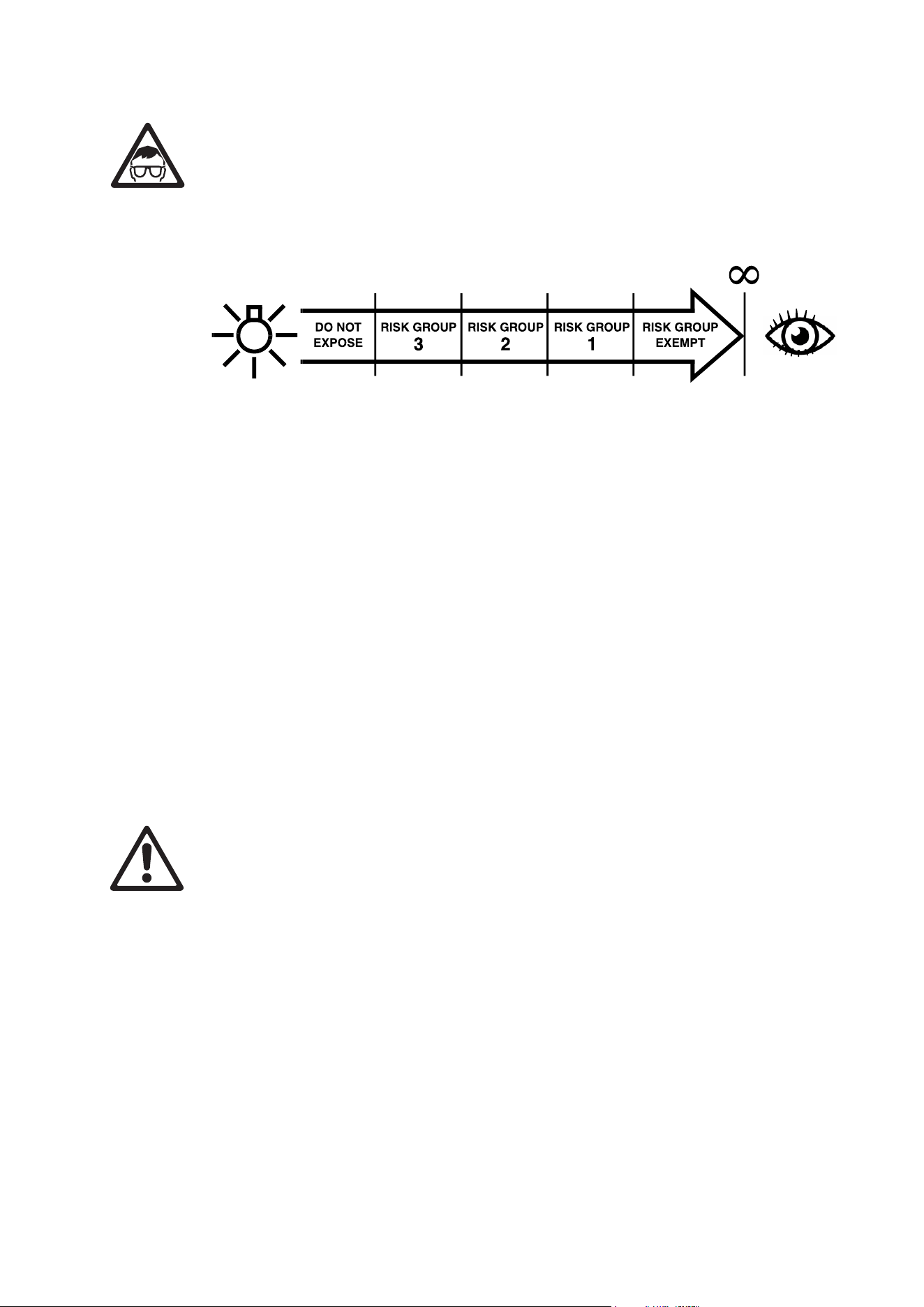
8 Martin
®
MAC Viper XIP Safety and Installation Manual Revision E
Protection from eye injury
This fixture corresponds to Application Group BLH-C according to EN IEC 62471-7 for stage
lighting, Risk Group 3 according to EN 62471 when all photobiological risks are considered
and Risk Group 2 according to IEC/TR 62778 for blue light only. It emits possibly hazardous
optical radiation. It falls into the Risk Group categories shown below according to EN 62471
and IEC/TR 62778 under worst-case conditions:
At a distance of less than 4.5 m (14.8 ft.) from the fixture, the light output can potentially
cause eye or skin injury before an exposed person's natural aversion responses (blink reflex
and reaction to skin discomfort) can protect them. At distances greater than 4.5 m (14.8 ft.),
potential eye and skin injury hazards from the light output are normally prevented by natural
aversion reflexes.
Position the fixture so that persons cannot be exposed to the fixture's light output at a
distance of less than 4.5 m (14.8 ft.) from the fixture and so that prolonged staring into the
light output at less than 56 m (184 ft.) is not expected.
Application Group BLH-C defines a time class (short time) <10 s that shall be respected
within the declared RG2 distance in the case of intentional effect lighting or unintentional
view into a stage luminaire.
Do not look directly into the fixture’s light output.
Do not look at the light output with magnifiers, telescopes, binoculars or similar optical
instruments that may concentrate the light output.
Ensure that persons are not looking directly into the front of the fixture when the product
lights up suddenly. This can happen when power is applied, when the product receives a
DMX signal, or when certain control menu items are selected.
Disconnect the fixture from power at all times when the fixture is not in use.
Provide well-lit conditions to reduce the pupil diameter of anyone working on or near the
fixture.
Protection from injury
The fixture weighs 37 kg (81.6 lbs.) not including rigging hardware.
When the fixture is in use, it must be either:
• fastened to a secure, stable structure such as a rigging truss, or
• standing on a stable horizontal surface where it will not present a danger of tripping or
falling.
Install the fixture only as directed in this manual.
The fixture is not portable when installed.
Ensure that all supporting structures and hardware used can hold at least six (6) times the
weight that they support (or more if required by locally applicable regulations).
Ensure that all rigging hardware items (rigging clamps, omega brackets etc.) are in perfect
condition, are approved by a professional body such as TÜV for the weight that they will
support, and that they comply with all locally applicable regulations.
Ensure that all supporting structures and rigging hardware items are suitable for the
installation environment and will be safe under all weather and temperature conditions.
0.2 m
(7.9 in.)
4.5 m
(14.8 ft.)
56 m
(184 ft.)
62 m
(204 ft.)

Martin
®
MAC Viper Safety and Installation Manual Revision E 9
Monitor weather conditions and take all appropriate safety precautions if a hazard is forecast
or present.
If suspending from a rigging structure, fasten the fixture to a truss or similar support using
two rigging clamps and omega brackets. Do not try to suspend the fixture from only one
rigging clamp. Do not use safety cables as the primary means of support.
When clamping a fixture to a truss or other supporting structure in any orientation apart from
hanging vertically with the head pointing downwards, use half-coupler-type rigging clamps.
Do not use G-clamps, quick-trigger clamps or any other type of clamp that does not
completely encircle the supporting structure when fastened.
If there is any danger that this product may cause injury or damage if the primary means of
attachment fails, secure it as described in this user manual with a securely anchored safety
cable that will catch it if it falls. Ensure that all safety cables used for secondary attachment
are in perfect condition, are approved by a professional body such as TÜV for the weight
that they will secure, and that they comply with all locally applicable regulations.
Remove as much slack as possible from the safety cable (by looping it more than once
around the chord of a rigging truss, for example). Make sure that, if a primary means of
attachment fails, the fixture cannot fall more than 20 cm (8 inches) maximum before the
safety cable catches it.
If the safety cable attachment point becomes deformed, do not suspend the fixture. Have
the fixture repaired by an authorized Martin service partner.
Allow enough clearance around the head to ensure that it cannot collide with an object or
another fixture when it moves.
Check that all external covers and rigging hardware are securely fastened.
Block access below the work area and work from a stable platform whenever installing,
servicing or moving the fixture. Make sure that there is no risk of injury from falling parts,
tools or other materials.
Do not operate the fixture with missing or damaged covers, shields or any optical
component.
Do not lift or carry the fixture by its head. Support the fixture by its base only.
In the event of an operating problem, stop using the fixture immediately and disconnect it
from power. Do not attempt to use a fixture that is obviously damaged.
Do not modify the fixture in any way not described in the fixture’s user documentation. Install
only parts and accessories that are supplied by or approved by Martin for the fixture.
Refer any service operation not described in this manual to Martin Service or an authorized
Martin service partner.

10 Martin
®
MAC Viper XIP Safety and Installation Manual Revision E
Introduction
Thank you for selecting the MAC Viper XIP moving head lighting fixture from Martin®.
This Safety and Installation Manual is supplied with the fixture. It gives details of installing and servicing
the fixture as well as connecting to mains power. The MAC Viper XIP User Manual, containing full
instructions for connecting to control data, setting up, controlling and monitoring the fixture is available for
download from the MAC Viper XIP area of the Martin website at www.martin.com. If you have any difficulty
locating this document, please contact your Martin supplier for assistance.
Before installing, operating or servicing the MAC Viper XIP, please check the fixture’s area of the Martin
website at www.martin.com and make sure that you have the latest user documentation for the product.
Not all product specifications are included in the fixture’s user documentation. You can find full
specifications for the fixture in the MAC Viper XIP area of the Martin website. The online specifications
include information to help you order accessories such as cables, flightcases etc.
The fixture is supplied with this Safety and Installation manual and two Martin omega brackets for
fastening a rigging clamp to the fixture base.
Packing and unpacking
Allow the fixture to cool for 30 minutes before packing it for storage or transport in a flightcase or
packaging. If the fixture is wet, wipe it with a soft, dry cloth and apply power until the fixture is completely
dry before packing. This will avoid moisture damage and mold.
If you move the fixture from a cold to a warm environment, remove it from its flightcase or packaging and
give it at least two hours to acclimatize before you apply power. This will help to avoid damage due to
internal condensation.
Condensation
When using the fixture in outdoor locations – especially locations with wide temperature variations and/or
high humidity – we recommend that you keep power applied to the fixture at all times in order to avoid
condensation inside the fixture. However, it is possible to shut down power to the fixture for up to 18 hours
if followed by a period of 6 hours with power applied.
Before using the product for the first time
1. Check the support pages on the Martin Professional website at www.martin.com for the most recent
user documentation and technical specifications for the fixture. Martin user manual revisions are
identified by the revision letter at the bottom of the inside cover.
2. Read ‘Safety information’ on page 4 before installing, operating or servicing the fixture.
3. Unpack and ensure that there is no transportation damage before using the fixture. Do not attempt to
operate a damaged fixture.
4. Check that the voltage and frequency of the local power source match the mains power requirements
of the fixture.
5. Either hard-wire the fixture’s power input cable to an AC mains power source or install as described in
this manual a power plug (cord cap) that is suitable for local power outlets on the power input cable
and connect the cable to an AC mains power outlet. If you need to fabricate a power cable, use only
the cable and connector specified in this manual.
Applying mains power
The fixture does not have an on/off switch. It becomes active as soon as AC mains power is applied at the
power input connector. Be prepared for the head to move and for the fixture to suddenly emit bright light.
Each time power is applied to the fixture, it will reset all effects and functions to their home positions. A
reset typically takes around 45 seconds.
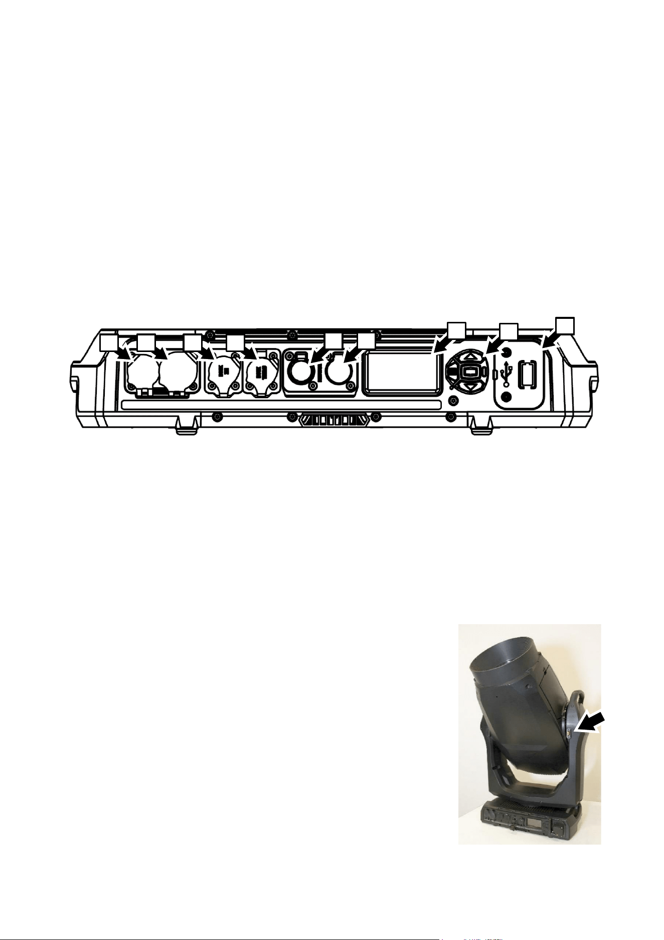
Martin
®
MAC Viper Safety and Installation Manual Revision E 11
Cold starting
At +5° C (41° F) and below, the fixture starts up in cold-start mode. In this mode, the current to some
motors is increased and reset speed is reduced. This makes sure that the fixture can reset safely without
any step loss. After a successful reset, the fixture stays in cold-start mode until it has warmed up. In cold-
start mode there is a slight increase in noise from the fixture. Some effects (especially gobo changes and
speed) are slower than normal.
The fixture exits cold-start mode as soon as it reaches an internal temperature of approximately 20° C
(68° F).
To warm up the fixture as quickly as possible, set LED output to full intensity. If you prefer the fixture not to
project light during warmup, set the CMY and CTO flags to 99%, i.e. almost fully closed, and set all
framing blades to 99%, i.e. almost fully inserted. Note that if you set these effects to 100%, LED output will
be shut down and the LED warmup effect will be lost.
Overview
A – AC mains power IN (accepts Neutrik
powerCON TRUE1 TOP or compatible)
B – AC mains power OUT/THRU (accepts
Neutrik powerCON TRUE1 TOP or
compatible)
C – DMX data IN (5-pin locking male XLR)
D – DMX data OUT/THRU (5-pin locking female
XLR)
E – Control data Ethernet port A in/out
F – Control data Ethernet port B in/out
G – Control panel display
H – Control buttons
I – Cover for CR123A lithium battery and
USB-C port (can be used with accessory
options)
Tilt lock
The fixture has a tilt lock located on the yoke (see illustration on right) that
can be applied during servicing, for example.
It is not necessary to release the tilt lock before transporting the MAC Viper
XIP in its Martin flightcase, but the head must be angled at approximately
45° to match the flightcase insert.
G
I
H
E
F
A
B
C
D

12 Martin
®
MAC Viper XIP Safety and Installation Manual Revision E
Physical installation
Warning! Read ‘Safety information’ on page 4 before installing the fixture.
To avoid head collisions when installing MAC Viper XIP fixtures next to each other,
allow a minimum center-to-center distance between fixtures of 704 mm (27.8 inches).
Martin can supply installation hardware such as rigging clamps and safety cables that are suitable for use
with the fixture (see the product specifications on the MAC Viper XIP product page on the Martin website
at www.martin.com).
Installation location
The MAC Viper XIP is designed for permanent or temporary indoor use or for temporary outdoor use. A
fixture with an ‘IP54 / Wet Locations’ rating can withstand rain and splashing water, but it cannot withstand
high pressure water jets or immersion in water.
Fasten the fixture to a secure structure or surface or stand it on a surface where it cannot be moved or fall
over. If you install the fixture in a location where it may cause injury or damage if it falls, secure it as
directed in this manual using a securely anchored safety cable that will hold the fixture if the primary
fastening method fails.
Installation environment
The fixture has a rugged construction and is designed to withstand temporary outdoor conditions.
However, it is not designed for use in extreme environments such as air with a high content of salt,
chlorine, acid or other aggressive agents. Exposure to harsh environmental conditions like these may
result in deterioration of the product that is not covered by the product warranty. If the fixture is exposed to
salt etc., rinse it carefully in pure water.
The fixture is designed and tested according to the IP54 standard. This means that the fixture is dust-
protected, not dust-tight. Ingress of dust is not entirely prevented, but it shall not enter in sufficient quantity
to interfere with the safe operation of the fixture. If the fixture is used in dusty or sandy environments,
cleaning will be required after use. Before using the fixture in a dusty or sandy environment, we
recommend that you replace the gauze air filters in the head with the disposable air filters with a paper
element that are available from Martin in sets of 12 (P/N 50400765). Air filter replacement takes no more
than a few seconds.
Avoiding damage from other light sources
Do not point the light output from other lighting fixtures at the MAC Viper XIP, as powerful light can
damage the display.
Standing the fixture on a flat surface
The fixture can be placed on a hard, fixed, flat horizontal surface provided that there is no risk that it may
cause an obstruction or be knocked over. Ensure that the surface can safely bear the weight of all items
that it will support, including any dynamic loads.
If you install the fixture in a location where it may cause injury or damage if it falls, secure it as directed in
this chapter with a securely anchored safety cable.
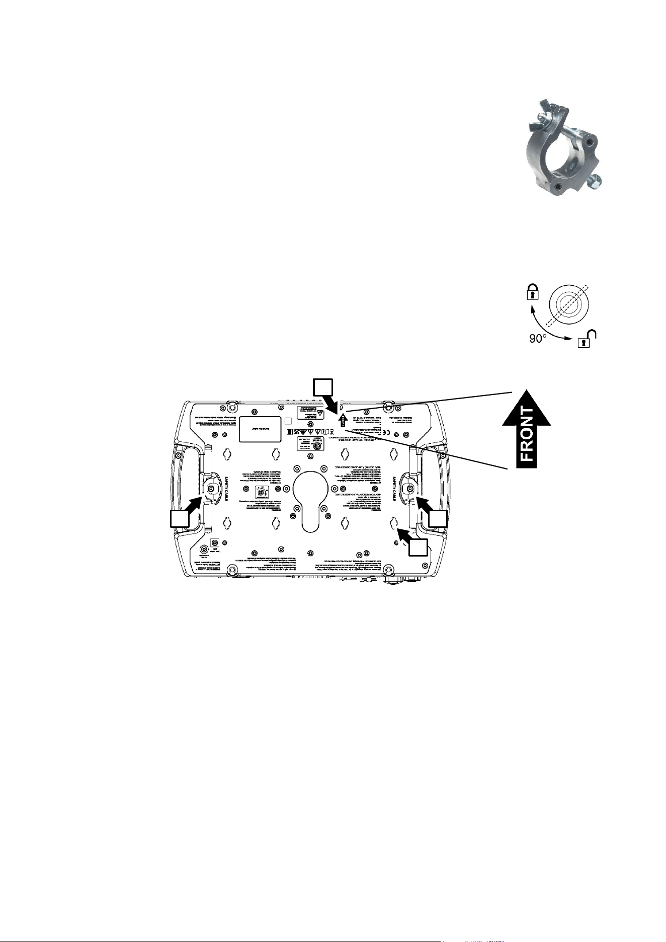
Martin
®
MAC Viper Safety and Installation Manual Revision E 13
Mounting the fixture on a truss
The fixture can be clamped to a truss or similar rigging structure in any orientation.
Use half-coupler type clamps (see illustration on right) that completely encircle the
truss chord or tubular support.
If installing the fixture outdoors, mount it so that the connections panel does not face
upwards. Ensure that cables arrive from below the fixture, creating ‘drip loops’ in
cables if necessary. Check that all rigging hardware is suitable for outdoor use.
To clamp the fixture to a truss:
1. Check that the rigging structure can support at least six times (or more if required
by local regulations) the weight of all fixtures and equipment to be installed on it.
2. Block access under the work area.
3. The fixture is supplied with two omega-type brackets. Bolt a half-coupler type rigging clamp that is in
perfect condition and approved for the weight that it will support securely to the each bracket. Use
M12, grade 8.8 steel minimum bolts with self-locking nuts.
4. Fasten the two omega brackets complete with rigging clamps to the base of the
fixture by locking each bracket’s quarter-turn fasteners into two of the receptacles
(see B in illustration below) in the base of the fixture. The brackets must be spaced
evenly. Turn quarter-turn fasteners a full 90° to lock them as shown on right.
5. Note the position of the arrow marked FRONT (see A in illustration above). Working from a stable
platform, hang the fixture on the truss and fasten the two rigging clamps onto the truss with FRONT
pointing towards the main area to be illuminated.
6. Secure the fixture with a safety cable as directed below.
7. Make sure that there is no possibility of the head colliding with other fixtures or objects when it moves
through its full pan and tilt ranges.
Securing with a safety cable
1. Obtain a safety cable that is approved for the weight of the fixture.
2. Fasten the cable to one of the safety cable attachment points in the base of the fixture (see C in
illustration on previous page) by either looping it around or fastening a carabiner clip to the attachment
point. Do not use one of the fixture’s carrying handles as the attachment point for the safety cable.
Half-coupler
clamp
A
B
C
C
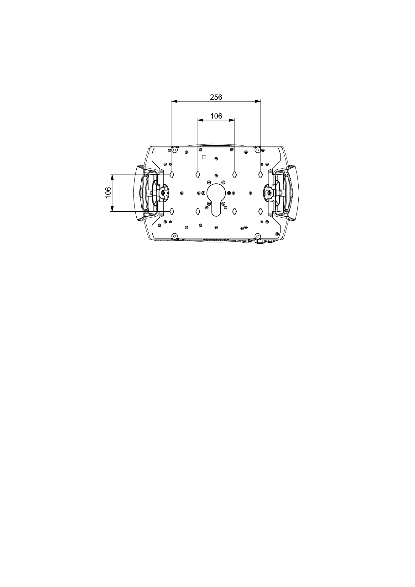
14 Martin
®
MAC Viper XIP Safety and Installation Manual Revision E
3. Remove as much slack as possible from the safety cable (by looping the cable around the truss chord,
for example) and fasten it to a secure anchoring point.
4. Make sure that the safety cable will hold the fixture if a primary attachment fails.
Quarter-turn receptacles in base

Martin
®
MAC Viper Safety and Installation Manual Revision E 15
AC mains power
Warning! Read ‘Safety information’ on page 4 before connecting the fixture to AC
mains power.
The fixture has an auto-ranging power supply that accepts AC mains power at 100-240 V at
50/60 Hz. Do not apply AC mains power at any other voltage or frequency to the fixture.
The fixture’s maximum current draw is as follows:
• At 100-120 V~: 11.0 A
• At 200-240 V~: 5.2 A
Typical half-cycle RMS inrush current: 17.0 A at 230 V, 50 Hz.
Typical earth-leakage current: 0.7 mA.
The fixture requires a power input cable with an IP65-rated Neutrik powerCON TRUE1 NAC3FX-W (TOP)
or equivalent female cable connector for AC mains power input. The cable must meet the requirements
listed under “Protection from electric shock” on page 5. Martin can supply suitable input cables with
connectors 1.5 m (4.9 ft.) or 5 m (16.4 ft.) long, as well as loose input connectors (see the Martin website
at www.martin.com).
The fixture can be hard-wired to a building electrical installation if you want to install it permanently.
Alternatively, you can connect it to local power outlets if you install a suitable power plug on the power
input cable. When installing a power plug, follow the plug manufacturer’s instructions and connect the
wires in the power cable following the color coding guide in the table below:
Live or L
Neutral or N
Earth, Ground or
US system
Black
White
Green
EU system
Brown
Blue
Yellow/green
If you need to install a Neutrik powerCON TRUE1 (TOP) or equivalent IP65-rated connector on a power
cable, follow the connector manufacturer’s instructions (normally published on the manufacturer’s website
or included with the product), respecting the color coding guide above.
Linking fixtures to power in a chain at 100-120 V
If you are supplying the fixture with AC mains power at 100-120 V, do not connect any other MAC Viper
XIP fixture to the mains power OUT/THRU socket on the fixture’s connections panel. Do not connect any
device to the mains power OUT/THRU that draws a current of more than 5 A.
Linking fixtures to power in a chain at 200-240 V
If you are supplying the fixture with AC mains power at 200-240 V, you can connect up to three (3) fixtures
in total to mains power in a linked daisy chain as follows:
1. Obtain a 12 AWG / 2.5 mm2 power input cable and 12 AWG / 2.5 mm2 power relay cables (available
from Martin – see the Martin website at www.martin.com).
2. Relay mains power from one fixture to another by connecting fixtures to power in a linked daisy-chain,
mains power OUT/THRU socket to mains power IN socket. This daisy-chain may contain up to a
maximum of three (3) fixtures total.

16 Martin
®
MAC Viper XIP Safety and Installation Manual Revision E
If you are supplying a fixture with AC mains power at 200-240 V, do not connect any device – or chain of
devices – that draws a current of more than 10.8 A to the mains power OUT/THRU socket of that first
fixture.
If you connect three fixtures to power in a daisy-chain, we recommend that you draw power from a circuit
that is protected by a type C MCB (Miniature Circuit Breaker). This will avoid the breaker tripping
unnecessarily due to inrush current.
Connecting to power
Connect the fixture to AC mains power by lining up the keys in the IP65 power input cable connector with
the keyways in the mains power IN connector in the connections panel, inserting the connector and
twisting clockwise. Twist the cable connector counterclockwise and remove it from the connections panel
to disconnect.
The mains power connectors support hot-plugging, but it is still good practice to shut down power to the
power input cable before connecting to or disconnecting from the fixture if you can do this without
inconvenience.
The fixture does not have an on/off switch. It becomes active as soon as power is applied at the power
input connector. Be prepared for the head to move suddenly and for the fixture to emit bright light as soon
as power is applied.
Data connections
See the MAC Viper XIP User Manual available for download from www.martin.com for full details of
connecting the fixture to control data.
Use shielded twisted-pair Ethernet cable of type S/UTP, SF/UTP, S/STP or SF/STP only for the data link.
The cable must be rated Cat 5e or better. The cable shield must be electrically connected to connector
housings, and the other devices on the data link must also support shielded connections.

Martin
®
MAC Viper Safety and Installation Manual Revision E 17
Service and maintenance
Warning! Read ‘Safety information’ on page 4 before servicing the fixture.
Refer any service or repair operation not described in this manual or in the
fixture’s User Manual to an authorized Martin service technician. Do not try to
carry out such an operation yourself, as doing so may present a health or safety
risk. It may also cause damage or malfunction, and it may void your product
warranty. The LED light source is not user-replaceable.
Installation, on-site service and maintenance can be provided worldwide by the Martin Professional Global
Service organization and its approved agents, giving owners access to Martin’s expertise and product
knowledge in a partnership that will ensure the highest level of performance throughout the product’s
lifetime. Please contact your Martin supplier for details.
The user must clean the MAC Viper XIP periodically to maintain optimum performance and cooling,
removing air filters from the head and base as described in this chapter for inspection and cleaning. The
user may replace the fixture’s 3-volt lithium battery as described in this chapter. The user may upload
firmware (fixture software) via the fixture’s DMX data input port, Ethernet port or USB-C port using
firmware from Martin and instructions in the fixture’s User Manual (available for download from the Martin
website at www.martin.com). The user may also install custom gobos as directed in the fixture’s User
Manual. Finally, the user may install or uninstall an optional wireless DMX accessory that fits onto the
fixture’s USB port following instructions from Martin. All other service operations on the MAC Viper XIP
must be carried out by Martin, its approved service agents or trained and qualified personnel using the
official Martin service documentation for the MAC Viper XIP.
It is Martin policy to apply the strictest possible calibration procedures and use the best quality materials
available to ensure optimum performance and the longest possible component lifetimes. However, optical
components are subject to wear and tear over the life of the product, resulting in gradual changes in color
over many thousands of hours of use. The extent of wear and tear depends heavily on operating
conditions and environment, so it is impossible to specify precisely whether and to what extent
performance will be affected. However, you may eventually need to replace optical components if their
characteristics are affected by wear and tear after an extended period of use and if you require fixtures to
perform within very precise optical and color parameters.
Service mode
Pressing MENU and ENTER buttons immediately when the fixture name appears in the display while
powering the fixture on puts the fixture into service mode, in which pan and tilt motors are deactivated and
SERV appears in the display. To take the fixture out of service mode, power off and then power on again
normally.
The MAC Viper XIP User Guide (available for download from the MAC Viper XIP page on
www.martin.com) gives full details of the menus in the fixture’s control panel.
Cleaning
Important! Excessive dust, smoke fluid, and particle buildup degrades performance, causes
overheating and will damage the fixture. Damage caused by inadequate cleaning or maintenance
is not covered by the product warranty.
At regular intervals, the front glass must be cleaned to optimize light output and air filters must be
removed for inspection and cleaning. Cleaning schedules for lighting fixtures vary greatly depending on
the operating environment. It is therefore impossible to specify precise cleaning intervals for the fixture.
Environmental factors that may result in a need for frequent cleaning include:
• Use of smoke or fog machines.
• High airflow rates (near air conditioning vents, for example).
• Presence of cigarette smoke.
• Airborne dust (from stage effects, building structures and fittings or the natural environment at outdoor
events, for example).
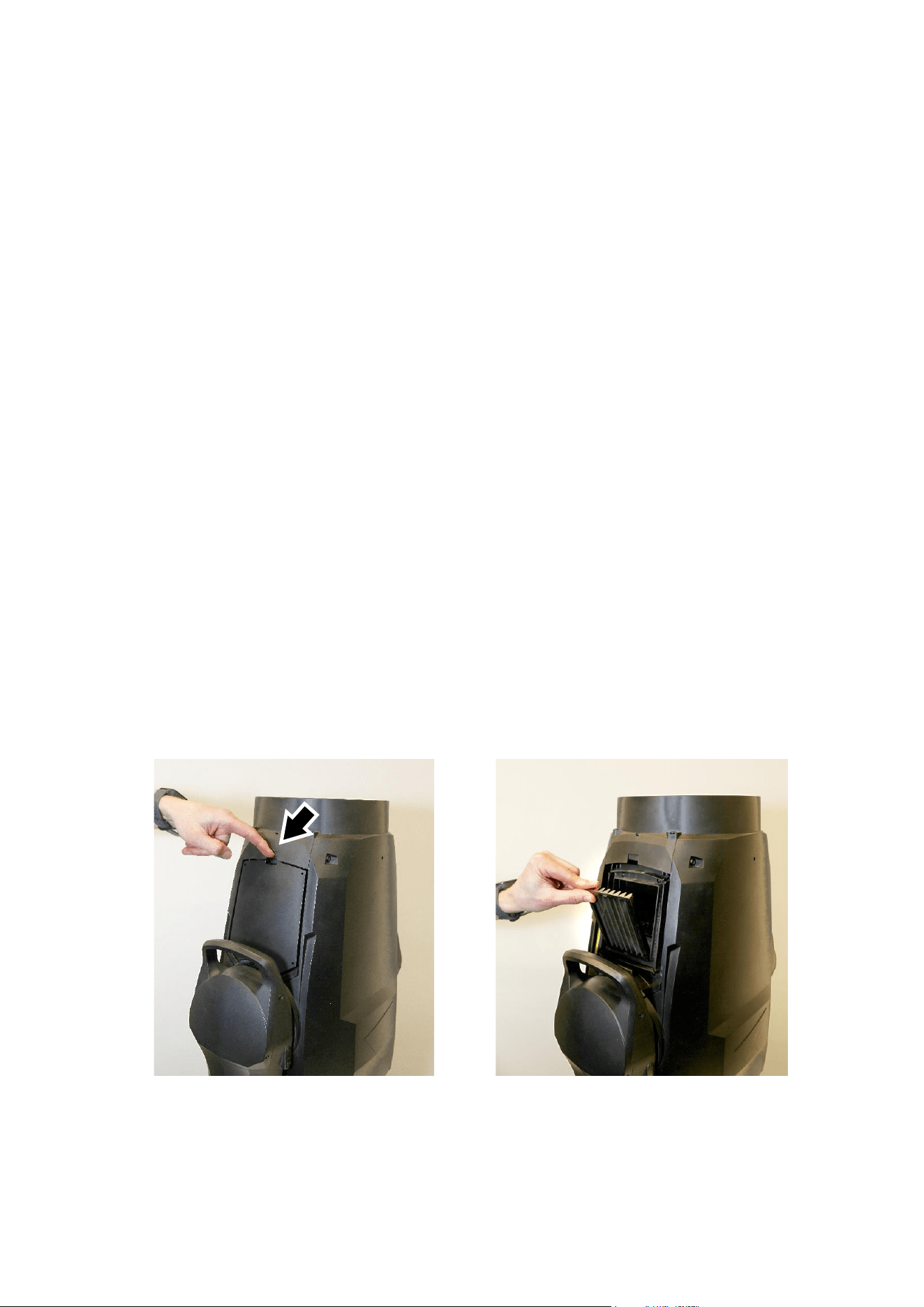
18 Martin
®
MAC Viper XIP Safety and Installation Manual Revision E
If one or more of these factors is present, inspect fixtures within their first 100 hours of operation to see
whether cleaning is necessary. Check again at frequent intervals. This procedure will allow you to assess
cleaning requirements in your particular situation. If in doubt, consult your Martin dealer about a suitable
maintenance schedule.
Use gentle pressure only when cleaning, and work in a clean, well-lit area. Do not use any product that
contains solvents or abrasives, as these can cause surface damage.
To clean the fixture:
1. Disconnect the fixture from power and allow it to cool for at least 15 minutes.
2. Vacuum or gently blow away dust and loose particles from the outside of the fixture and air vents with
low-pressure compressed air. Holding cooling fan blades stationary with a screwdriver will protect
them from spinning too fast and possibly being damaged when you apply a vacuum or air jet.
3. Clean surfaces using warm water with a little detergent and a soft cloth, sponge or soft brush of the
type used for washing cars. Do not rub glass surfaces hard: lift particles off with a soft repeated press.
Dry with a soft, clean, lint-free cloth or low-pressure compressed air. Remove stuck particles with an
unscented tissue or cotton swab moistened with glass cleaner or distilled water.
4. Wipe the fixture with a soft, dry cloth after cleaning. We recommend that you apply power to the fixture
for a short time, which will allow it to warm up slightly and dry out completely, before putting it into
storage.
Cleaning air filters
The MAC Viper XIP has two wire gauze air filters in the head (one on either side of the head) and two wire
gauze air filters in the base. When using the fixture in dusty conditions we recommend the use of head air
filters with paper elements. These are available as accessories in sets of 12 from Martin suppliers by
ordering P/N 50400765.
Head air filters
To service the head air filters:
1. Disconnect the fixture from power and allow to cool for 30 minutes.
2. Position the head pointing upwards so that the head air filter covers are accessible.
3. See illustrations below. Release the latches (arrowed) and remove the two head air filter covers, one
on each side of the head. Remove the air filters from their recesses in the head.
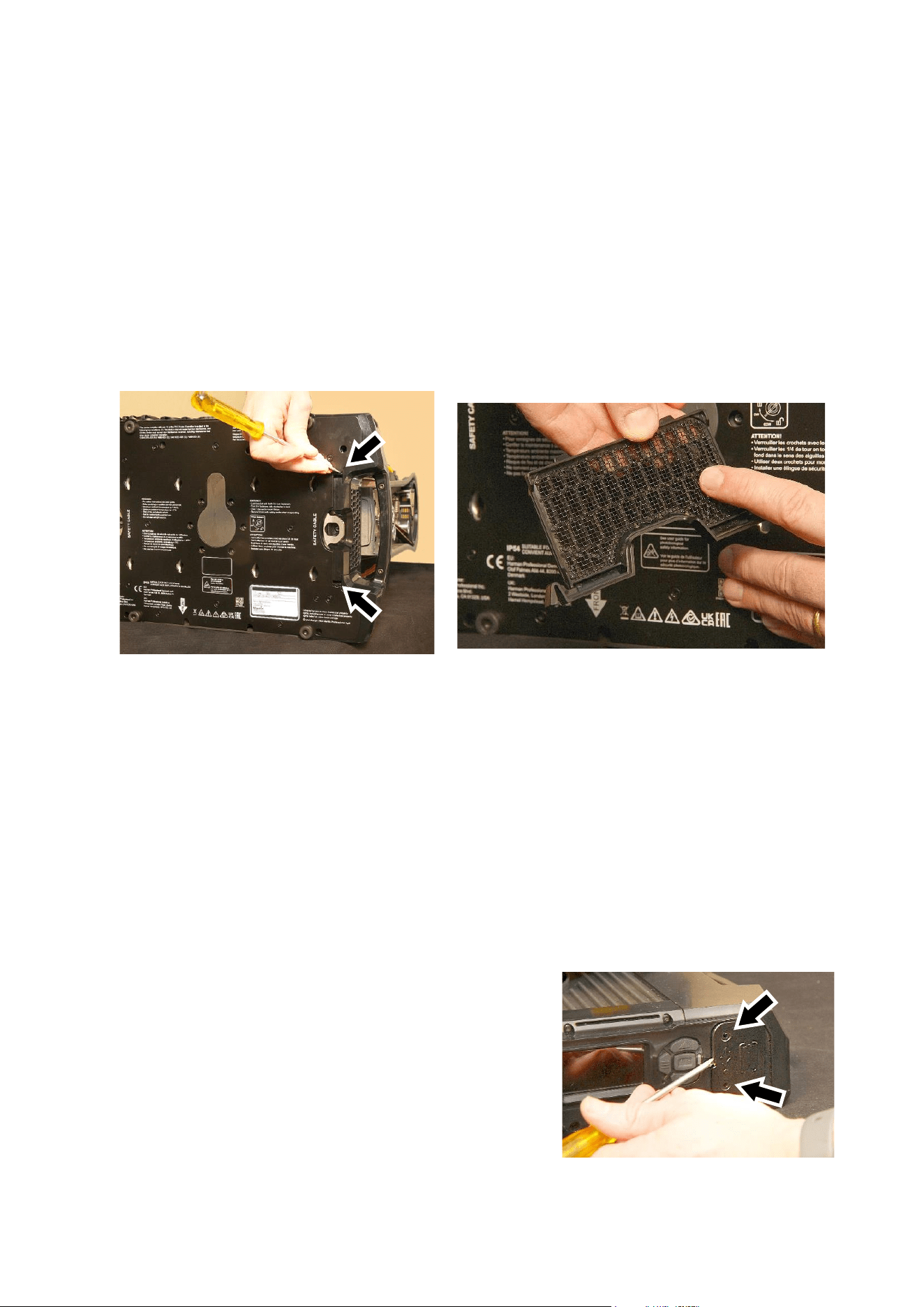
Martin
®
MAC Viper Safety and Installation Manual Revision E 19
4. Dispose of paper air filters. Do not try to clean or re-use a paper air filter. Clean metal air filters with a
soft brush and vacuum cleaner or compressed air, taking care to avoid damaging the filter mesh. If
metal filters are greasy, you can clean them in a household dishwasher at maximum 50° C (122° F),
short cycle recommended. Dry them completely before reinstalling. The metal filter is designed to be
re-used, but replace it with a new item if it is not in clean, undamaged condition after cleaning.
5. Place the clean air filters into their recesses in the head, making sure that there is no gap for air to
pass around the edges of the filter.
6. Hook the rear end of each filter cover into the head and push the front end into the head until its clip
engages fully. Check that the covers are held securely and cannot fall out of the head.
Base air filters
To service the base air filters:
1. See illustrations below. For each of the two air filters, push on the air filter cover retaining clips
(arrowed) to release them, then remove the filter from the base.
2. Remove dust from each filter with a soft brush and/or low-pressure compressed air. Remove grease
with warm soapy water. You can clean the filters in a household dishwasher at maximum 50° C (122°
F), short cycle recommended.
3. Dry each filter carefully, then push it back into its recess in the base until both retaining clips lock into
place. Make sure that the filter is held securely.
Battery replacement
Warning! Disconnect the fixture from AC power before replacing its battery. Do not attempt to
recharge the battery, or you may create a risk of fire or explosion.
The MAC Viper XIP has a non-rechargeable 3-volt lithium battery that provides power to the control panel
and display when the fixture is not connected to AC mains power. If the battery runs flat, you must replace
it. Do not attempt to recharge it.
The battery is located behind a cover in the USB port / battery compartment next to the control panel on
the base of the fixture. If a wireless DMX module accessory is installed, the battery is behind this module.
To replace the battery:
1. Order Martin P/N 05801011 (CR123A, 3 V lithium battery).
2. Disconnect the fixture from AC mains power and allow to
cool.
3. See illustration on right. Remove the two Torx10 screws
from their holes (arrowed) in the black USB port / battery
compartment cover.
4. Carefully lever the cover off the fixture base with a flathead
screwdriver. Take care not to damage seals.

20 Martin
®
MAC Viper XIP Safety and Installation Manual Revision E
5. See illustration on right. The battery is located behind a
yellow rubber cover. Pull the yellow cover off the battery
compartment and remove the used battery.
6. Insert the new CR123A battery, respecting the correct
battery polarity (positive terminal facing upwards,
towards the head).
7. Reinstall the yellow rubber cover over the battery
compartment. Check the condition of the seal on the
black cover (or the wireless DMX module, if used) that
fits over the USB port / battery compartment. The seal
must be in perfect condition. If not, contact your Martin
supplier for a replacement. Install the cover (or module), fastening it in position with its two screws.
Check that it is closed securely before reapplying power.
8. Dispose of the used battery responsibly: send to an authorized waste recycling and disposal center.
Installing a Universal Connect Module Accessory
The MAC Viper XIP User Manual available for download from the Martin website at www.martin.com
contains instructions for installing a wireless Universal Connect Module accessory.
Lubrication
The MAC Viper XIP does not require lubrication under normal circumstances. Moving parts can be
checked and a long-lasting Teflon-based grease reapplied by a Martin service partner if necessary.
Seal care
The yellow rubber seals, particularly on the fixture’s head, can become sticky over time. This can make
covers difficult to remove and you can risk displacing or deforming seals during cover removal. To make
service easier and protect the seals, apply a very thin film of silicone grease to them. Apply just enough
grease to act as a release agent and wipe off any excess. The grease should hardly be visible when it is
correctly applied.

Martin
®
MAC Viper Safety and Installation Manual Revision E 21
Specifications
For full product specifications, see the MAC Viper XIP area of the Martin website at www.martin.com
FCC compliance
This equipment has been tested and found to comply with the limits for a Class B digital device, pursuant
to part 15 of the FCC Rules. These limits are designed to provide reasonable protection against harmful
interference in a residential installation. This equipment generates, uses and can radiate radio frequency
energy and, if not installed and used in accordance with the instructions, may cause harmful interference
to radio communications. However, there is no guarantee that interference will not occur in a particular
installation. If this equipment does cause harmful interference to radio or television reception, which can
be determined by turning the equipment off and on, the user is encouraged to try to correct the
interference by one or more of the following measures:
• Reorient or relocate the receiving antenna.
• Increase the separation between the equipment and receiver.
• Connect the equipment into an outlet on a circuit different from that to which the receiver is connected.
• Consult the dealer or an experienced radio/TV technician for help.
FCC supplier’s declaration of conformity declaration
This device complies with part 15 of the FCC Rules. Operation is subject to the following two conditions:
• This device may not cause harmful interference.
• This device must accept any interference received, including interference that may cause undesired
operation.
Canadian Interference-Causing Equipment Regulations – Règlement sur le Matériel Brouilleur du
Canada
This Class B digital apparatus meets all requirements of the Canadian Interference-Causing Equipment
Regulations.Cet appareil numérique de la classe B respecte toutes les exigences du Règlement sur le
Matériel Brouilleur du Canada.
CAN ICES (B) / NMB (B)
EU Declaration of Conformity
Harman Professional, Inc. hereby declares that the equipment type MAC Viper XIP complies with the
following: European Union Restriction of Hazardous Substances Recast (RoHS2) Directive 2011/65/EU
and as amended by 2015/863; European Radio Equipment Directive (RED) 2014/53/EU.
Type: NFC tag
Frequency: 13.56 MHz
The full text of the EU Declaration of Conformity covering this product is available for download from the
MAC Viper XIP product area of the Martin website at www.martin.com.
Conditional connection
For conformity with mains voltage fluctuations and flicker according to EN61000-3-11 during extensive use
of continuous strobe effects the user must determine, in consultation with the mains power supply
authority if necessary, that the equipment is connected to a supply impedance of less than 0.39 ohms at
50 Hz.
Disposing of this product
Martin products are supplied in compliance with Directive 2012/19/EC of the European
Parliament and of the Council of the European Union on WEEE (Waste Electrical and
Electronic Equipment), where applicable.
Help preserve the environment! Ensure that this product is recycled at the end of its life.
Your supplier can give details of local arrangements for the disposal of Martin products

www.martin.com
