315-750-4008
RELIABLE EFFICIENT VALUE
This manual contains important safety precautions. Read and understand this manual carefully
before using the product. Failure to follow these instructions may result in serious injury.
The specifications, descriptions, and illustrations in this manual are as accurate as possible at
the time of publication, but are subject to change without notice.
Keep this manual with the product for future reference.
www.mechmaxx.com
OPERATOR’S MANUAL
EN
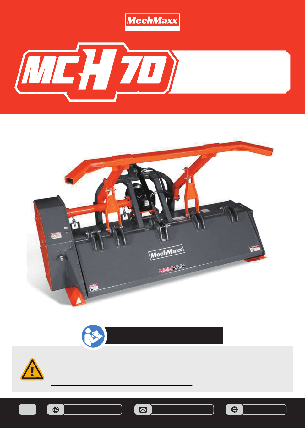
70" 3-POINT
HITCH BRUSH
MULCHER

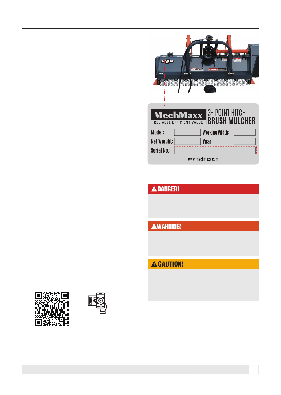
70" 3-POINT HITCH BRUSH MULCHER
Before operating the machine, please read this
manual carefully and make sure you understand all
safety warnings, assembly instructions, operating
procedures, maintenance requirements, and
troubleshooting information. Proper assembly, safe
operation, and regular maintenance will help ensure
reliable performance, extend the service life of the
machine, and reduce the risk of personal injury or
equipment damage.
The illustrations and specifications in this manual
are for reference only. The actual product may vary
slightly due to model configuration, production
updates, or technical improvements. If you have any
questions during assembly, operation, or mainte-
nance, stop using the machine and contact your
dealer or service representative for assistance.
This machine is designed for specific applications
only. We strongly recommend that this machine not
be modified or used for any application other than
its intended purpose. If you have any questions
regarding a particular application, DO NOT use the
machine until you have contacted us to determine
whether the application can or should be performed
with this product.
Use only genuine MechMaxx parts when servicing or
repairing this machine. Replacement parts
manufactured by other companies may fit this
machine, but they may present potential safety
hazards. Replacement parts can be purchased from
your authorized MechMaxx dealer.
• The serial number of your machine
• The part number
• The part description
• The quantity needed
1
INTRODUCTION
INTRODUCTION
Indicates an imminently hazardous situation
which, if not avoids, will result in death or serious
injury.
SCAN THE QR CODE TO
CONTACT US
Indicates a potentially hazardous situation which,
if not avoided, could result in death or serious
injury.
Indicates a potentially hazardous situation which,
if not avoided, may result in minor or moderate
injury. It may also be used to alert against unsafe
practices.
Ordering Parts
Safety Definitions

70" 3-POINT HITCH BRUSH MULCHER
Overall Dimensions
TABLE OF CONTENTS
TABLE OF CONTENTS
TABLE OF CONTENTS
SPECIFICATIONS
SAFETY SIGNS
SAFETY
2
3
3
6
Finishing the Work
Trap Door
14
Push Working
13
14
MAINTENANCE 15
Safety First
15
Replacing Drive Belts
16
Tighten All Bolts
16
Tightening Torque
17
Visual Inspection
18
Tool Replacement
18
PARTS DIAGRAM
19
Parts List
20
Personal Safety
General Safety
Prior to Operation
Description and Applications
6
6
6
Operational Safety – Work Area
7
The Hazard Zone
7
Hazard Zone Precautions
7
Dangerous Locations
7
Precautions
7
Urban Precautions
8
Stopping the Rotor Before Exiting the Carrier
ASSEMBLY
Safety Frame Assembly
4
6
8
8
8
8
10
10
ATTACH MULCHER TO TRACTOR
11
Mounting Instructions
11
Hydraulic Hose Connection
11
PTO Shaft Adjustment
11
Avoid Power Lines
Operator Protection
Carrier Cab Protection
13
MULCHER OPERATION
13
Pull Working
15
Rotor Drive Belts
16
Lubrication Points
2
70" 3-POINT HITCH BRUSH MULCHER
SPECIFICATIONS
3
SPECIFICATIONS
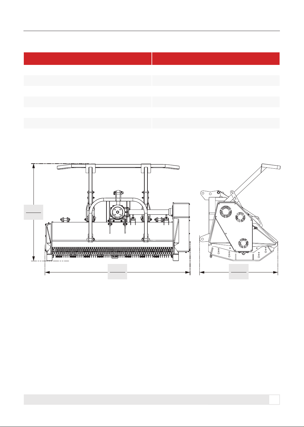
Model MCH70
Recommended PTO HP
Working Width
PTO Speed
Number Of Blades
3-Point Hitch
Weight
Gearbox Oil Type
70-110 HP
70 in
540 RPM
32 pcs
CAT 2
1984 lbs
85W-90
1430mm
56.3”
2176mm
85.6”
1142mm
44.9”
Overall Dimensions
70" 3-POINT HITCH BRUSH MULCHER
4
SAFETY SIGNS
SAFETY SIGNS
The SAFETY SYMBOL indicates there is a potential hazard to personal safety involved and extra safety
precaution must be taken. When you see this symbol, be alert and carefully read the message that follows it. In
addition to design and configuration of equipment, hazard control and accident prevention are dependent upon
the awareness, concern, prudence and proper training of personnel involved in the operation, transport,
maintenance and storage of equipment.
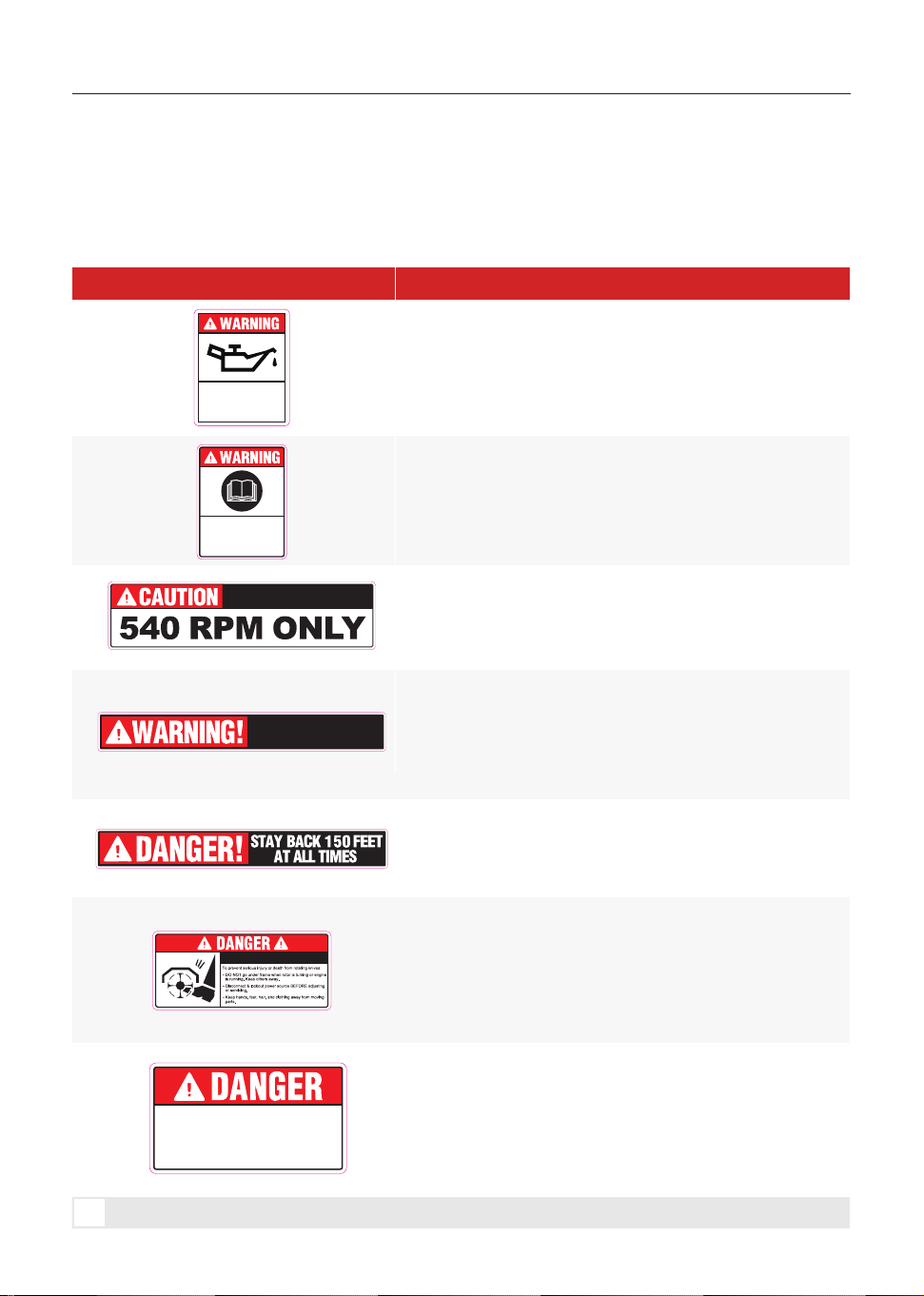
ENGINE OIL WARNING LABEL
This label reminds users to add the correct engine oil before
first use to prevent engine damage.
OPERATOR’S MANUAL WARNING LABEL
This label reminds users to read and understand the
operator’s manual before using the machine.
PTO SPEED CAUTION LABEL
This label warns users to operate the machine only with a
540 RPM PTO to avoid injury or machine damage.
REVERSE MOWING WARNING LABEL
This label warns users not to mow in reverse, as doing so
may cause damage to the mower.
STAY BACK DANGER LABEL
This label warns all bystanders to stay at least 150 ft away
from the machine during operation.
ROTATING KNIVES DANGER LABEL
This label warns users to keep away from rotating knives. Do
not go under the frame while the rotor or engine is running.
Disconnect and lock out the power source before adjustment
or service.
GUARD MISSING DANGER LABEL
This label warns users not to operate the machine if the
guard is missing or removed, as this creates an entangle-
ment hazard.
LABEL MEANING
MUST ADD OIL
BEFORE FIRST
USE
ROTATING KNIVES HAZARD
GUARD MISSING.
WHEN THIS IS VISIBLE,
DO NOT OPERATE.
ENTANGLEMENT HAZARD.
To avoid Injury or Machine Damage:
Operate only with 540 rpm PTO
DO NOT MOW IN REVERSE,
OR DAMAGE WILL OCCUR
TO YOUR MOWER!
Read and
understand the
operator’s manual
before using this
machine.
70" 3-POINT HITCH BRUSH MULCHER
5
SAFETY SIGNS
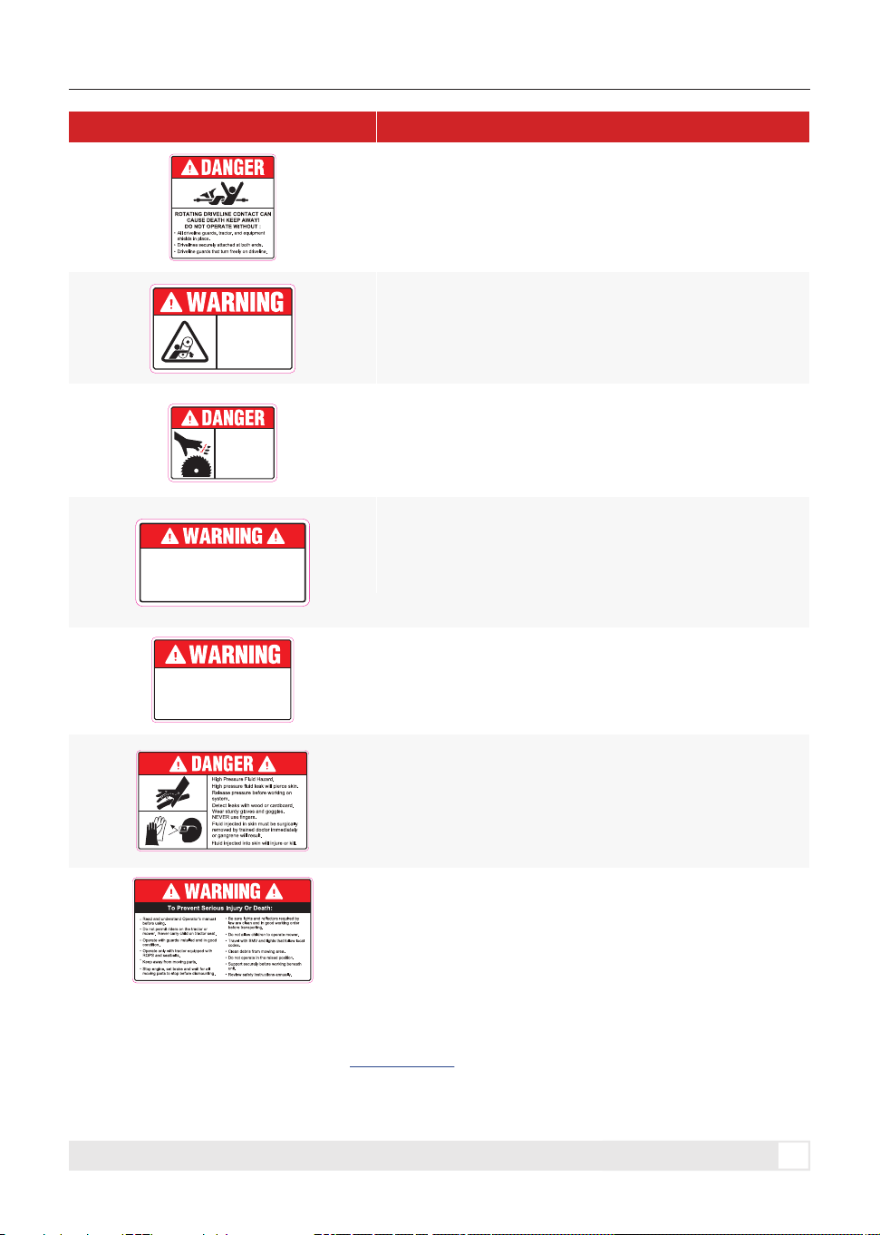
They were designed to help you safely operate your implement. Read and follow their directions.
1. Keep all safety labels clean and legible.
2. Replace all damaged or missing labels. mechmaxx.com
3. Some replacement components installed during repair require safety labels to be affixed as specified by
MechMaxx. When ordering new components make sure the correct safety labels are included in the request.
ROTATING
BLADES
KEEP HANDS
AWAY
ROTATING DRIVELINE DANGER LABEL
This label warns users to keep away from the rotating
driveline. Do not operate the machine unless all driveline
guards, tractor shields, and equipment shields are installed
and the driveline is securely attached.
BELT DRIVE WARNING LABEL
This label warns users of hand and arm entanglement
hazards from the belt drive. Do not open or remove safety
shields while the engine is running.
ROTATING BLADES DANGER LABEL
This label warns users to keep hands away from rotating
blades. Contact with the blades can cause serious injury or
amputation.
PTO DRIVELINE WARNING LABEL
This label warns users to measure and cut the PTO driveline
according to the owner’s manual before operation. Incorrect
driveline length may damage both the tractor and the
implement.
HIGH PRESSURE FLUID DANGER LABEL
This label warns users that high-pressure fluid leaks can
pierce the skin and cause serious injury or death. Release
system pressure before service, use wood or cardboard to
check for leaks, and never use fingers.
PTO STARTUP WARNING LABEL
This label warns users to engage the tractor clutch slowly
during startup to prevent damage. Keep the PTO shaft within
25° of level during operation.
GENERAL SAFETY WARNING LABEL
This label reminds users to read the manual, keep guards in
place, stay away from moving parts, keep children away,
clear debris, and stop the engine before service or dismount-
ing.
LABEL MEANING
ENGAGE THE TRACTOR CLUTCH
SLOWLY DURING STARTUP, OR
DAMAGE MAY OCCUR. KEEP THE
PTO SHAFT WITHIN 25° OF LEVEL
DURING OPERATION.
The PTO driveline MUST be measured
and cut, if required, according to the
Owner’s Manual. Failure to do so will
result in damage to both the tractor
and the implement.
BELT DRIVE:
HAND AND ARM
ENTANGLEMENT
HAZARD.
Do not open or remove
safety shields while engine is
running.
70" 3-POINT HITCH BRUSH MULCHER
6
General Safety
SAFETY
SAFETY
With any piece of equipment, new or used, the most
important part of its operation is safety! We
encourages you and your employees to familiarize
yourselves with your new equipment and to stress
safe operation!!
Do not operate the machine while under the
influence of alcohol, drugs, or medication that may
affect your ability to operate it safely.
• Read the owner's manual in its entirety and follow
all safety procedures.
• Check all grease points per the owner's manual.
• Inspect all fasteners for tightness with power off.
• Manually turn rotor to inspect tool bolts with
engine off.
• Check the gearbox oil (PTO models) for the proper
level per the owner’s manual.
• Obey all safety labels on the forestry mulcher.
They are provided for your protection. If any labels
are removed, damaged, or made unreadable in any
way, call your dealer for a replacement.
The hitch brush mulcher is built for demanding brush
shredding, land clearing, trail maintenance, and
stump grinding applications. Its heavy-duty fixed
tools are designed to cut through dense vegetation
and reduce material into fine mulch.
By making repeated passes over the material, the
mulcher helps achieve the desired particle size and
finish. The shredded mulch can be left on the ground
to help retain moisture, improve soil condition, and
provide temporary erosion control on slopes.
Do not wear loose clothing, shorts, sandals, or
jewelry. Tie back long hair so that it is above
shoulder level.
Personal Safety
Prior to Operation
Description and Applications
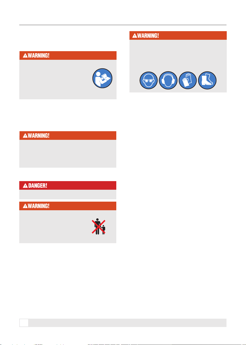
Read and understand this manual
and all safety labels attached to the
machine before operation. Become
familiar with the machine’s
controls, limitations, proper
operation, and potential hazards.
If this machine is loaned, rented, sold, or used by
someone other than the original purchaser,
always provide this manual and proper safety
training before operation.
Keep children, pets, and
bystanders away from the work
area. Stop the machine
immediately if anyone enters the
operating area.
Always wear proper personal protective
equipment during operation, including safety
glasses with side shields, hearing protection,
gloves, heavy long pants, and protective
footwear.
Never allow children to operate this machine.

70" 3-POINT HITCH BRUSH MULCHER
7
SAFETY
For the purpose of this manual, the front of the
mulcher refers to the side where the rotor is
exposed. The rear of the mulcher refers to the side
equipped with deflection chains.
For crawler or rubber-tire carrier machines, if the
mulcher is mounted on the front of the machine, the
front of the mulcher faces the same forward
direction as the carrier. If the mulcher is mounted on
the rear of the machine, the front of the mulcher
faces away from the rear of the carrier.
Mounting positions may vary for excavators and
other boom-type machines. However, all references
to the front and rear of the mulcher in this manual
remain based on the rotor side and deflection-chain
side.
Flying debris, thrown objects, and falling objects can
cause serious injury or death. Improper operation or
failure to follow safety precautions may also result
in serious injury or death.
All personnel must stay clear of the hazard zone
while the mulcher is operating. The shaded area in
the figure must be considered off limits to all
individuals.
The operator must follow the precautions below
before and during mulcher operation.
Operational Safety – Work Area
The Hazard Zone
It is the operator’s responsibility to make sure that
no one enters the hazard zone.
Warn all persons in the area about the hazard zone
before starting operation.
Stay alert for bystanders or unauthorized persons
entering the work area who may not be aware of the
hazard.
Land clearing operations often involve other
machines, vehicles, and workers on the jobsite.
Always be aware of surrounding traffic and activity.
Maintain a safe clearance of at least 150 ft (45 m)
on each side of the mulcher and 300 ft (90 m) in
front of and behind the mulcher during operation.
Flying debris, thrown objects, and falling objects can
cause serious injury or death. Improper operation or
failure to follow safety precautions may also result
in serious injury or death.
All personnel must stay clear of the hazard zone
while the mulcher is operating. The most dangerous
areas are directly in front of and behind the mulcher.
Wood pieces, rocks, and other debris may be thrown
from the mulcher, especially when the mulcher is
raised high enough for material to escape
1. Never allow anyone to enter the safety zone while
the mulcher is operating.
2. Inspect the carrier and mulcher daily for damaged
or missing deflection chains, guards, and flaps.
Use extra caution in the following situations:
• When the mulcher is being raised out of the
material being processed.
• When the mulcher is being lowered into new
material.
• When working near rocks, wood debris, or uneven
ground.
If equipped, close the hydraulic trap door during
pull-working to help contain material and produce a
finer shredded result.
Hazard Zone Precautions
Dangerous Locations
Precautions
Hitch Brush
Mulcher
300 ft (90 m)
300 ft (90 m)
300 ft (90 m)
300 ft (90 m)

70" 3-POINT HITCH BRUSH MULCHER
Additional safety procedures and precautions are
required when operating the mulcher in or near
populated areas, including:
• Streets or highways
• Parks, golf courses, or other public areas
• Residential, commercial, or occupied areas
• Buildings, fences, utilities, or other structures
Before operation, establish safety controls suitable
for the jobsite. Secure the work area with colored
warning tape, cones, signs, or barriers as needed.
When working near highways or roads, place
warning signs at least 1,000 ft (300 m) before the
edge of the hazard zone. Use a traffic director
whenever the hazard zone may affect pedestrian or
vehicle traffic.
Keep all pedestrians, vehicles, and unauthorized
persons outside the hazard zone at all times.
Contact with overhead power lines can cause
serious injury or death. Never allow any part of the
equipment, attachment, or carried material to come
close to an electric line.
Maintain a minimum clearance of 3 m (10 ft) plus
twice the length of the line insulator from all power
lines. Use a signal person to guide the operator
when working near overhead lines. Use approved
protective covers, shrouds, or insulators when
required.
Always be aware of the direction in which trees may
fall. Direct falling trees away from power lines at all
times.
Flying debris, thrown objects, and falling objects can
cause serious injury or death. The operator must be
properly protected before operating the mulcher.
Replace any damaged, missing, or weakened
polycarbonate windows, guards, or falling object
protection components before operation.
Improper operation or failure to follow safety
precautions may result in serious injury or death. All
personnel must stay clear of the hazard zone while
the mulcher is operating.
For PTO Carriers
Install 1/2 in. (1.25 cm) thick polycarbonate, or
equivalent material, in place of or outside the cab
glass between the operator and the mulcher.
A steel mesh screen with a maximum opening size
of 2 in. (5 cm) and a wire diameter of 1/4 in. (0.6
cm) is recommended outside the cab, between the
mulcher and the operator, to help protect the
polycarbonate from scratches and damage.
For Forestry Prime Movers with Enclosed Cabs
Install 1/2 in. (1.25 cm) thick polycarbonate, or
equivalent material, in place of or outside the cab
glass between the operator and the mulcher.
A steel mesh screen with a maximum opening size
of 2 in. (5 cm) and a wire diameter of 1/4 in. (0.6
cm) is recommended outside the cab, between the
mulcher and the operator.
For Excavators and Boom-Type Carriers with
Enclosed Cabs
The front cab window facing the boom should be
protected with 1/2 in. (1.25 cm) thick polycarbonate,
or equivalent material, installed in place of or
outside the cab glass between the operator and the
mulcher.
A steel mesh screen with a maximum opening size
of 2 in. (5 cm) and a wire diameter of 1/4 in. (0.6
cm) is recommended outside the cab, between the
mulcher and the operator, to help protect the
polycarbonate from scratches and damage.
Contact with a moving rotor can cause serious injury
or death. Never exit the carrier until the rotor has
completely stopped.
To stop the rotor:
1. Lower the engine speed to idle.
2. Shut off the mulcher hydraulic circuit or PTO
drive.
3. If safe to do so, lower the mulcher and allow the
rotor to contact the ground or debris until it stops.
If there is no safe place to stop the rotor, remain in
the cab and wait until the rotor has come to a
complete stop before exiting.
Urban Precautions
Avoid Power Lines
Operator Protection
Carrier Cab Protection
Stopping the Rotor Before Exiting the
Carrier
8
SAFETY

70" 3-POINT HITCH BRUSH MULCHER
Even if certain safety precautions are not specifically mentioned above, always remain alert, follow
safe operating practices, and operate the machine properly according to this manual and the engine
manual.
9
SAFETY
70" 3-POINT HITCH BRUSH MULCHER
ASSEMBLY
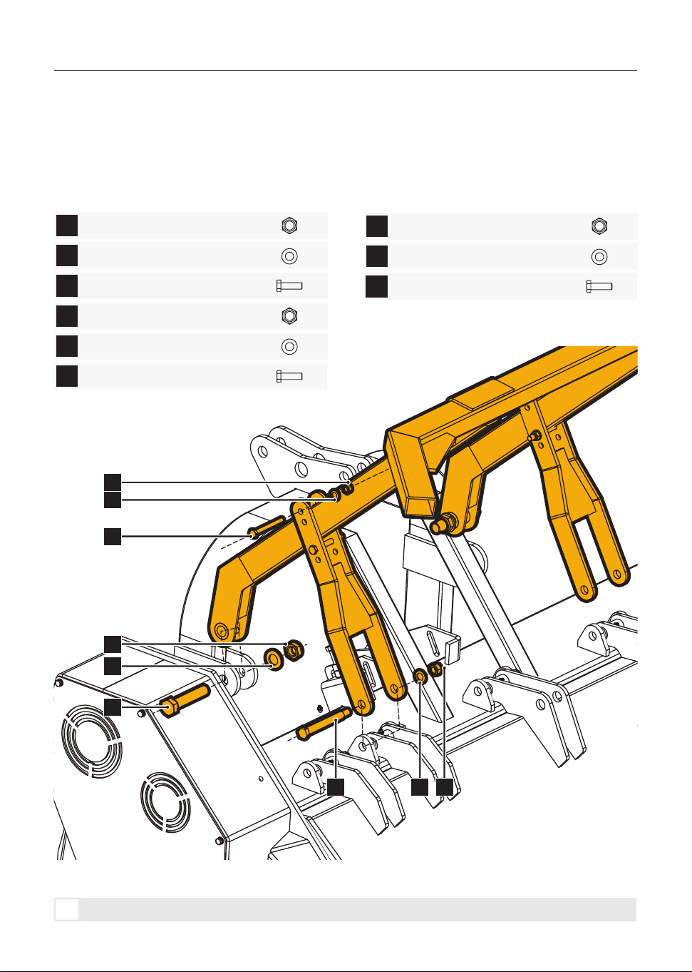
1. Secure the safety frame to the headstock using Hex Bolt M24 × 120, Flat Washer 24, and Hex Nut M24.
2. Install the brackets onto the safety frame using Flat Washer 12, Hex Bolt M12 × 100, and Hex Nut M12.
3. Secure the safety frame using the fixing shaft, Flat Washer 16, and Hex Nut M16.
Hex lock nut M24
X2A
C
B
Hex bolt M24 X 120mm
Flat washer 24
X2
X2
Hex lock nut M12
X2D
F
E
Hex bolt M12 X 100mm
Flat washer 12
X2
X2
Hex lock nut M16
X2G
I
H
Fixing Shaft
Flat washer 16
X2
X2
Safety Frame Assembly
10
C
B
A
F
E
D
I H
G
ASSEMBLY

70" 3-POINT HITCH BRUSH MULCHER
ATTACH MULCHER TO TRACTOR
The following instructions will help you attach the
brush mulcher to your tractor.
The brush mulcher uses a 3-point hitch system for
easy installation. If you have installed 3-point hitch
equipment before, attaching the brush mulcher
should be straightforward.
IMPORTANT: A front counterweight may be required
for safe transportation and operation of the tractor
and brush mulcher. At least 20% of the gross vehicle
weight must remain on the tractor’s front axle.
11
1.Park the tractor and brush mulcher on firm, level
ground.
2.Stop the tractor engine, set the parking brake, and
remove the ignition key before installation.
3.Make sure the tractor horsepower and hitch
category are within the required range for the brush
mulcher.
4.Slowly back the tractor toward the brush mulcher
until the lower 3-point hitch arms are aligned with
the lower hitch pins on the brush mulcher.
5.Attach the lower hitch arms to the lower hitch pins
and secure them with locking pins or linchpins.
6.Attach the tractor top link to the upper hitch point
of the brush mulcher and secure it with the proper
pin.
7.Adjust the top link until the brush mulcher is level
and properly positioned.
8.Stabilize the lower 3-point hitch arms to prevent
excessive side-to-side movement.
9.Connect the PTO shaft to the tractor PTO output
shaft and the brush mulcher gearbox input shaft.
Make sure the locking devices are fully engaged.
10.Check that the PTO shaft length is suitable and
that the shaft can telescope freely throughout the
full lifting range.
11.Attach the PTO shaft safety chains to prevent the
guards from rotating.
12.Slowly raise and lower the brush mulcher with the
tractor 3-point hitch to check for proper clearance.
Make sure the PTO shaft does not bind or contact
the tractor or brush mulcher.
13.Check all pins, bolts, guards, and shields before
operation. Make sure everything is securely
installed.
14.Start the tractor at low idle, engage the PTO
slowly, and check that the brush mulcher operates
smoothly before beginning work.
Note: To disconnect the brush mulcher from the
tractor, follow the above steps in reverse order.
When connecting the brush mulcher to the tractor,
route the hydraulic hoses as far away from the
operator as possible. Keep the hoses away from
sharp edges and prevent them from dragging on the
ground.
1.Stop the tractor engine, set the parking brake, and
relieve all hydraulic pressure before connecting the
hydraulic hoses.
2.Clean the hydraulic couplers on both the tractor
and the brush mulcher to prevent dirt or contami-
nants from entering the hydraulic system.
3.Connect the brush mulcher hydraulic hoses to the
tractor auxiliary hydraulic outlets. Make sure each
quick coupler is fully seated and locked.
4.Route the hydraulic hoses away from the operator,
PTO shaft, sharp edges, moving parts, and hot
surfaces. Do not allow the hoses to drag on the
ground.
5.Slowly operate the tractor hydraulic control lever
to check that the brush mulcher hydraulic functions
work properly.
6.Check all hydraulic connections for leaks. Use
cardboard or wood to check for leaks; never use
your hands.
7.If any leak, abnormal movement, or hose
interference is found, stop the tractor, relieve
hydraulic pressure, and correct the problem before
operation.
Mounting Instructions
Hydraulic Hose Connection
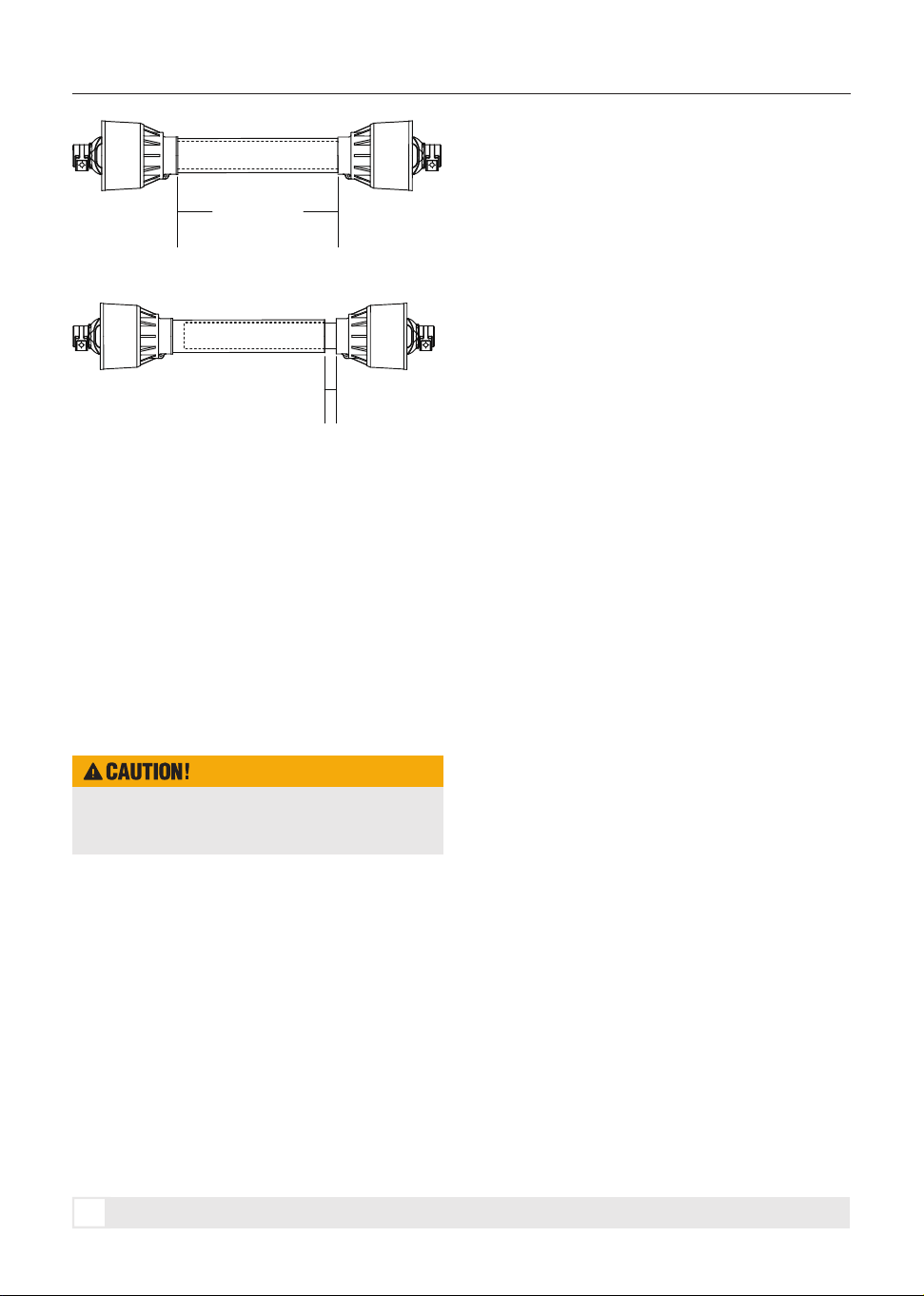
The PTO shaft assembly may need to be shortened
to fit your tractor properly. This helps prevent the
driveline from bottoming out, which could cause
serious damage to the tractor PTO drive system,
gearbox, or driveline components.
PTO Shaft Adjustment
ATTACH MULCHER TO TRACTOR
70" 3-POINT HITCH BRUSH MULCHER
12
The PTO shaft assembly is at its shortest length
when the brush mulcher is lowered and the PTO
shaft is straight and aligned with the brush mulcher
gearbox. There must be at least 0.50 in. of free
travel before the shaft is fully retracted.
To check:
a. Lower the brush mulcher until the PTO shaft is
parallel to the ground and aligned straight with the
brush mulcher gearbox.
b. Check that there is at least 0.50 in. of free travel
before the shaft is fully retracted.
If there is not at least 0.50 in. of free travel, the PTO
shaft must be shortened before operation.
Failure to maintain the required clearance may
damage the tractor PTO.
FULLY
RETRACTED
0.50” (13mm) FREE TRAVEL
ATTACH MULCHER TO TRACTOR

70" 3-POINT HITCH BRUSH MULCHER
13
MULCHER OPERATION
Flying debris, thrown objects, and falling objects
can cause serious injury or death. Before
operating the mulcher, make sure all personnel
are outside the hazard zone as described in the
Safety section of this manual.
Flying debris, thrown objects, and falling objects
can cause serious injury or death. Before
changing direction, make sure all personnel are
outside the hazard zone.
The following instructions are intended to help
ensure safe and effective operation of the brush
mulcher. Read this section carefully and use
extreme caution at all times.
Raise the mulcher head above the material to be
processed, or as high as practical. Retract the
hydraulic top link on three-point hitch carriers, or
retract the tilt cylinders on loader-arm carriers, to
rotate the mulcher and trap door upward. This
exposes more of the rotor area to the material.
Move the carrier forward slowly to engage the
material.
If the mulcher is equipped with a trap door, place the
trap door in the open position to allow maximum
exposure of the mulching tools.
Fully engage the material and lower the mulcher
head as the work allows. If engine RPM begins to
drop, slowly move the carrier backward while
continuing to lower the head.
As the head approaches the ground, rotate the head
downward carefully. Do not rotate the head too
quickly.
Control carrier speed and cutting depth by
monitoring engine RPM. Do not allow the engine
speed to drop below its proper torque range, or
below the point where the engine can quickly recover
after the load is reduced.
After the material has been knocked down, position
the mulcher for pull-working. This mode is used to
complete the shredding and finishing work.
Begin pull-back shredding when the deflection
chains are slightly off the ground and the front
corner of the mulcher shoes contacts the ground.
For a finer grind, raise the head slightly after ground
contact.
Move the carrier slowly backward so the material is
repeatedly ground against the counter combs inside
the mulcher body.
If equipped, close the trap door to retain as much
material as possible inside the mulcher shroud. This
improves shredding performance and helps contain
debris.
Operate in low gear. Raise and lower the mulcher
head slightly as needed according to engine RPM
and cutting load.
For loose stumps, tilt the cutter head back, raise it
above the stump, and slowly lower it to remove a
layer from the stump. Repeat this process as
needed.
As a general rule, do not rotate the cutter head
forward. The rotor may catch the loose stump and
throw it toward the carrier.
In some cases, it may be better to use the rotor to
create a small hole and roll the stump into it. This
helps hold the stump in place during grinding.
Lower the mulcher to keep the stump engaged and
pinned to the ground. Continue grinding downward
as the tools climb up and over the stump.
Repeat the process, removing the stump gradually.
Work only an inch or two at a time and use extreme
caution to avoid ejecting the stump under or toward
the carrier.
For stumps still fixed in the ground, move the carrier
back and forth while gradually lowering the cutter
head.
Stump grinding is most effective in the forward
direction. This allows the rotor to move over the
stump while using the added force of gravity and
forward motion.
Push Working
Loose Stumps
Fixed Stumps
Pull Working
MULCHER OPERATION

70" 3-POINT HITCH BRUSH MULCHER
14
NOTICE: Moving the rotor back and forth changes
the angle of attack, changes the cutting arc of the
tools, reduces continuous friction, tears the fibers
laterally, and helps split tree fibers horizontally.
After material has been knocked down, shredded,
and stumps have been removed, perform the final
finishing grind.
Final grinding should be done while moving
backward. Raise the head clear of the material and
move forward to begin each finishing pass.
Begin pull-back shredding when the deflection
chains are slightly off the ground and the front
corner of the mulcher shoes contacts the ground.
The slower the carrier speed, the finer the finished
mulch.
The trap door has two main functions:
1. It opens to maximize exposure of the mulching
tools during take-down operation.
2. It closes to contain brush and debris inside the
mulcher shroud for improved shredding during
pull-working and finishing operation.
NOTICE: The trap door must be open when taking
down trees and heavy brush. The door may be
damaged if it is rammed into heavy material while
closed.
Finishing the Work
Trap Door
MULCHER OPERATION
70" 3-POINT HITCH BRUSH MULCHER
15
MAINTENANCE
MAINTENANCE
Proper preventive maintenance helps ensure that the
mulcher performs at its full capability and reduces
unnecessary breakdowns caused by neglect.
The manufacturer’s warranty is conditional upon
following all recommended maintenance
procedures.
Before performing maintenance, follow these safety
precautions:
• Service the machine only on flat, firm, and stable
ground.
• Disconnect the PTO driveline and place it in the
holding chain. This applies to PTO-driven
machines only.
• To raise the rotor above ground level, adjust the
depth shoes downward or place the depth shoes
securely on firm blocks.
• Raising the rotor allows it to be rotated for
cleaning, belt replacement, or tool replacement.
During maintenance, rotate the rotor by hand only.
• Always check that the mulcher is stable before
reaching under or into the machine.
• Use only original replacement parts for repairs.
When the mulcher is attached to the carrier, the
weight of the mulcher may reduce weight on the
carrier’s front axle. During transport, at least 20% of
the carrier’s unladen weight must remain on the
front axle to ensure reliable steering and reduce the
risk of tipping backward. Add front ballast to the
carrier if necessary.
The mulching rotor is driven by power drive belts.
Before inspecting, adjusting, or replacing the rotor
drive belts:
• Shut off the engine.
• Depressurize the carrier hydraulic system.
• Wait until all machine components have complete-
ly stopped before touching them.
• Use lockout/tagout procedures in accordance with
29 CFR 1910.147 during inspection or mainte-
nance when required.
• Secure lifting cylinders with approved locking
devices before entering any hazardous area.
• Install safety locks and support devices before
working under or near raised components.
Refer to the Safety section of this manual for
additional information.
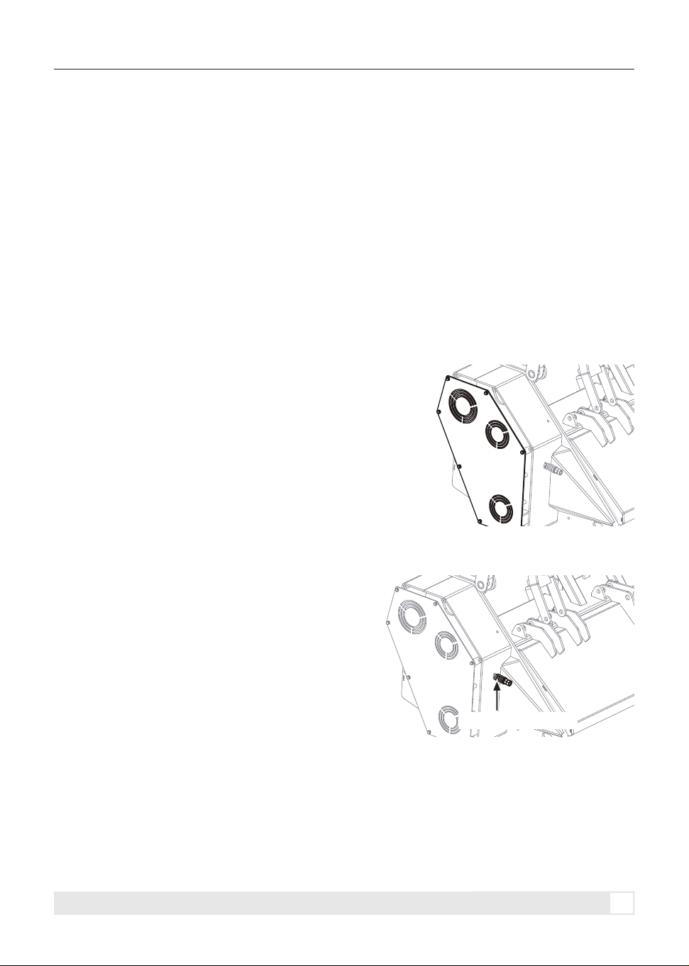
After the first 8 hours of operation, re-tension the
belts.
Check belt tension every 10–20 working hours, and
check more frequently during the first 24 to 48 hours
of operation.
To check and adjust belt tension:
1.Remove the inspection plates from the side
access panels to check belt tension.
2.Loosen the fixing screws until the bearing housing
can be moved with the adjustment bolt.
The ideal belt tension is the lowest tension at which
the belt will not slip under peak load.
Do not over-tension the belts. Excessive belt tension
will shorten belt and bearing life.
Keep belts clean and free from foreign material that
may cause slipping.
Safety First
Adjusting Rotor Drive Belt Tension
Rotor Drive Belts
Belt Adjustment Bolt
70" 3-POINT HITCH BRUSH MULCHER
16
MAINTENANCE
Over-lubricating sealed drive bearings may cause
premature seal failure, bearing failure, premature
shaft wear, or hydraulic motor shaft failure.
Never apply belt dressing. Belt dressing may
damage the belt and cause premature failure.
When proper belt tension is achieved:
1. Lock the adjustment bolt.
2. Tighten the fixing screws securely.
Before lubrication or maintenance:
• Shut off the engine.
• Depressurize the carrier hydraulic system.
• Wait until all machine components have complete-
ly stopped before touching them.
Grease the rotor bearings daily.
Use 1 pump of grease for each hour of operation.
For best results and longer component life, apply 4
pumps of grease after every 4 hours of operation.
If grease is found inside the belt housing, reduce the
frequency of lubrication.
Drive Shaft Bearing Housing
Grease the drive shaft bearing housing every 50
hours. Apply 1–2 pumps maximum.
Open the front access panels on each side and use a
hand grease pump only.
Excess lubrication may increase the operating
temperature of the bearing housing.
The mulcher is assembled with high-grade fasteners
and locking nuts where applicable. All fasteners are
tightened to the proper torque range during
assembly.
However, the forces generated during mulcher
operation may cause bolts to loosen.
Check all bolts and fasteners for tightness after the
first 10 hours of operation. After that, check all bolts
daily before operation.
Lubrication Points
Tighten All Bolts
Rotor Bearings
Replacing Drive Belts
The hitch brush mulcher must be level when
checking the gearbox oil level. Do not overfill.
Check Gearbox oil
Type of Lubrication: SAE 85W-90 Gear Lube.
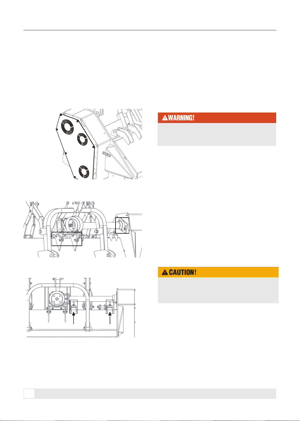
1.Remove the inspection plates from the side
access panels to check belt tension.
2.Before removing the belt, loosen the bolts shown
in the figure first.
4. Use a thin rod-like tool to carefully separate the
belt from the pulley.
5.Remove the old belt and install the new belt onto
the pulleys.
6.After adjusting the belt to the proper tension,
reinstall the inspection plate securely.
3.Then adjust the two belt tensioning bolts to
release belt tension.

70" 3-POINT HITCH BRUSH MULCHER
17
MAINTENANCE
Please follow the table below to identify the torque value as required.
Tightening Torque
Torque tolerance +0%,-15% of torquing values. Unless otherwise specified use torque values listed above.
1
in-tpi = nominal thread diameter in inches-threads per
inch
2
N.m= newton-meters
3
ft-lb= foot pounds
4
mm x pitch = nominal thread diameter in millimeters x
thread pitch
TORQUE VALUES CHART FOR COMMON BOLT SIZES
Grade 2 Grade 5
Bolt Head Identification Bolt Head Identification
Grade 8 Class 5.8 Class 8.8 Class 10.9
Bolt Size
(Inches)
in-tpi
1
Bolt Size
(Inches)
mm x pitch
4
N.m
2
N.m
ft-lb
3
ft-lb
N.m
ft-lb
N.m
ft-lb
N.m
ft-lb
N.m
ft-lb
1/4"-20
1/4"-28
5/16"-18
5/16"-24
3/8" -16
3/8" -24
7/16" -14
7/16"-20
1/2" -13
1/2" -20
9/16"-12
9/16"-18
5/8" - 11
5/8" -18
3/4" -10
3/4" -16
7/8" -9
7/8" -14
1"-8
1"-12
1-1/8"-7
1-1/8" -12
1-1/4"-7
1-1/4" -12
1-3/8"-6
1-3/8" -12
1-1/2" -6
1-1/2" -12
M5X0.8
M6X1
M8X 1.25
M8X1
M10X 1.5
M10X0.75
M12X 1.75
M12X 1.5
M12X1
M14 X2
M14 X 1.5
M16X2
M16X 1.5
M18 X 2.5
M18 X 1.5
M20 X 2.5
M20 X 1.5
M24X3
M24 X2
M30 X 3.5
M30×2
M36 X3.5
M36X2
4
7
17
18
33
39
58
60
90
92
99
145
155
195
220
280
310
480
525
960
1060
1730
1880
3
5
12
13
25
29
42
44
66
68
73
105
115
145
165
205
230
355
390
705
785
1270
1380
6
11
26
28
52
61
91
95
105
145
155
225
240
310
350
440
650
760
830
1510
1680
2650
2960
5
8
19
21
39
45
67
70
77
105
115
165
180
230
260
325
480
560
610
1120
1240
1950
2190
9
15
36
39
72
85
125
130
145
200
215
315
335
405
485
610
900
1050
1150
2100
2320
3660
4100
7
11
27
29
53
62
93
97
105
150
160
230
245
300
355
450
665
780
845
1550
1710
2700
3220
7.4
8.5
15
17
27
31
43
49
66
75
95
105
130
150
235
260
225
250
340
370
480
540
680
750
890
1010
1180
1330
5.6
6
11
13
20
22
32
36
49
55
70
79
97
110
170
190
165
185
250
275
355
395
500
555
655
745
870
980
11
13
24
26
42
47
67
75
105
115
150
165
205
230
360
405
585
640
875
955
1080
1210
1520
1680
1990
2270
2640
2970
8
10
17
19
31
35
49
55
76
85
110
120
150
170
265
295
430
475
645
705
795
890
1120
1240
1470
1670
1950
2190
16
18
33
37
59
67
95
105
145
165
210
235
285
325
510
570
820
905
1230
1350
1750
1960
2460
2730
3230
3680
4290
4820
12
14
25
27
44
49
70
78
105
120
155
170
210
240
375
420
605
670
910
995
1290
1440
1820
2010
2380
2710
3160
3560
8.85.8 10.9

70" 3-POINT HITCH BRUSH MULCHER
Visual Inspection
Tool Replacement
18
MAINTENANCE
Check the tools daily for the following:
• Lateral clearance
• Bolt tightness
• Condition of carbide tips
• Cracks, wear, or missing components
Refer to the model-specific parts manual for the
correct torque values.
After the first 20 to 40 hours of operation, check all
tools for proper torque. Failure to check tool torque
after the initial break-in period may result in tool or
tool holder failure.
1. Remove the fixing bolts.
2. Remove the old tool and install the new tool.
3. Install new fixing bolts.
4. Tighten the bolts to the factory-specified torque
value. Refer to the model-specific parts manual
for the correct torque specification.
Use only factory-supplied high-strength bolts.
NOTICE: Always use new hardware when replacing
tools to ensure proper torque and secure installa-
tion.
70" 3-POINT HITCH BRUSH MULCHER
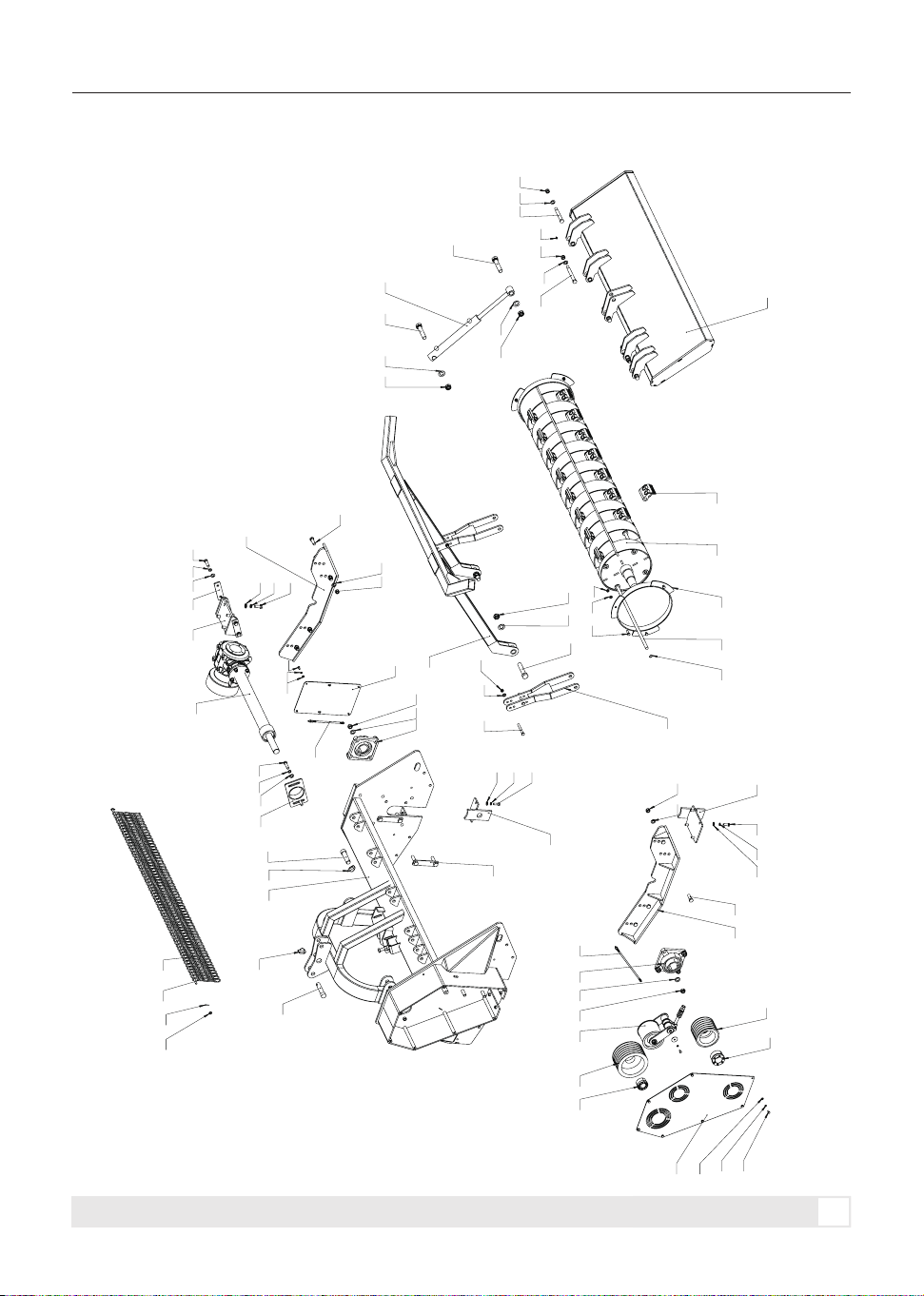
PARTS DIAGRAM
19
PARTS DIAGRAM
1
2
3
6
10
5
4
13
7
8
9
11
12
14
15
16
17
19
18
21
20
22
23
41
42
49
30
29 26 28
40
39
43
464748
44 45
46
47
48
28
40
39
49
42
41
52
51 50
27
52 51 50
56
57
44
45 44
43
58 48
59
53
54 55
535455 34
53
55 54
44
45
36
44 45
32
37
60 61
62
61 38
25 33
31
31
65
66

70" 3-POINT HITCH BRUSH MULCHER
Parts List
NO.
DESCRIPTION
QTY.
1
2
3
4
5
6
7
8
9
10
11
12
13
14
15
16
17
18
19
20
21
22
23
24
25
26
27
28
29
30
31
32
33
34
1
1
1
1
1
1
1
1
1
2
1
4
2
4
2
1
1
1
1
2
3
1
2
1
1
1
1
2
1
1
3
32
60
1
Frame Weldment
Base Weldment 1
Base Weldment 2
Support Seat Weldment 1
Support Seat Weldment 2
Mulching Rotor Weldment
Guard Weldment
Adjustment Seat Weldment
Gearbox Seat Weldment
Support Bracket Weldment
Safety Frame Weldment
Fixing Bolt Weldment
Guard Weldment
Knife Shaft
Fixing Plate
Small Pulley
Large Pulley
Cover Plate 1
Cover Plate 2
Fixed Shaft 1
Fixed Shaft 2
Pin Shaft
Pin Shaft 2
Flat Washer
Drag Chain Shaft
Tensioner Pulley Assembly
Gearbox Assembly
Bearing with Square Housing UCF212
Taper Lock Bushing
Taper Lock Bushing
11 x 45 Ring-Type O Pin
Knife
Deflection Chain
Hydraulic Cylinder
20
PARTS DIAGRAM

70" 3-POINT HITCH BRUSH MULCHER
NO.
DESCRIPTION
QTY.
35
36
37
38
39
40
41
42
43
44
45
46
47
48
49
50
51
52
53
54
55
56
57
58
59
60
61
62
63
64
65
66
1
5
8
2
8
8
18
18
8
17
13
6
6
10
17
6
6
6
4
4
4
4
4
4
4
6
8
6
2
2
1
1
Drive Shaft Dust Cover
Straight Pressure Grease Fitting M8 x 1
Internal Circlip 19
Cotter Pin 3 x 20
Non-Metallic Insert Hex Thin Lock Nut M18
Flat Washer 18
Hex Head Bolt, Full Thread M8 x 16
Spring Washer 8
Hex Head Bolt, Full Thread M16 x 50
Flat Washer 16
Non-Metallic Insert Hex Thin Lock Nut M16
Hex Head Bolt, Full Thread M12 x 35
Spring Washer 12
Flat Washer 12
Flat Washer 8
Hex Head Bolt, Full Thread M14 x 55
Spring Washer 14
Flat Washer 14
Hex Head Bolt, Half Thread M24 x 120
Flat Washer 24
Non-Metallic Insert Hex Thin Lock Nut M24
Hex Head Bolt, Full Thread M16 x 40
Spring Washer 16
Hex Head Bolt, Half Thread M12 x 100
Non-Metallic Insert Hex Thin Lock Nut M12
Hex Head Bolt, Full Thread M10 x 35
Flat Washer 10
Non-Metallic Insert Hex Thin Lock Nut M10
Hex Head Bolt, Full Thread M16 x 80
Hex Nut M16
Grease Hose Assembly 1
Grease Hose Assembly 2
21
PARTS DIAGRAM

RELIABLE EFFICIENT VALUE
315-750-4008
Our company is committed to continuous product improvement. The actual
product may differ from the pictures or descriptions in this manual. Specifica-
tions and design are subject to change without prior notice.
www.mechmaxx.com