ITEM #5971313
MODEL #L1120I
AS24010
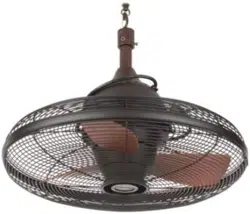
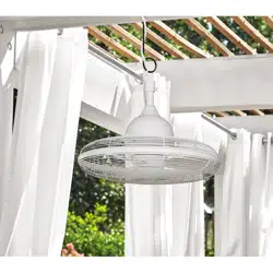
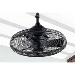
VALDOSTA PORTABLE FAN
Español p.13
ATTACH YOUR RECEIPT HERE
Thanks you for purchasing this HARBOR BREEZE product.
Questions, problems or missing parts?
Before returning, contact us on:
888-251-1003, 8 a.m. - 8 p. m., EST, Monday - Sunday or [email protected].
Serial Number
Purchase Date
Serial Number
Purchase Date

2
TABLE OF CONTENTS
Package Contents...............................................................................................................
Hardware Contents.............................................................................................................
Safety Information...............................................................................................................
Preparation .........................................................................................................................
Assembly Instructions...........................................................................................................
Operating Instructions ........................................................................................................
Care and Maintenance .......................................................................................................
Troubleshooting...................................................................................................................
FCC Warning........................................................................................................................
3
4
4
5
5
8
10
10
11
Limited Lifetime Warranty....................................................................................................
Replacement Parts List ......................................................................................................
11
12
3
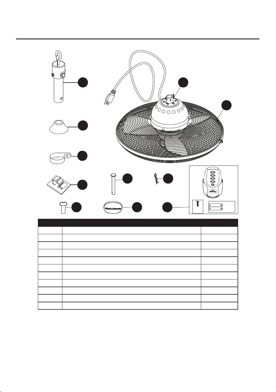
PACKAGE CONTENTS
PART DESCRIPTION QUANTITY
A Downrod Assembly 1
B Coupling Cover 1
C Rod Clip 1
D Motor Body 1
E Wire Clip 6
F Coupling (Preassembled to the Motor Body (D)) 1
G Cross Pin (Preassembled to Coupling (F)) 1
H Clip (Preassembled to Coupling (F)) 1
I Coupling Screw (Preassembled to Coupling (F)) 2
J Decorative cover 1
K Remote Unit 1
A
B
C
G H
I
E
D
F
J K
OFF
HI
MED
LO
x2
x2
4
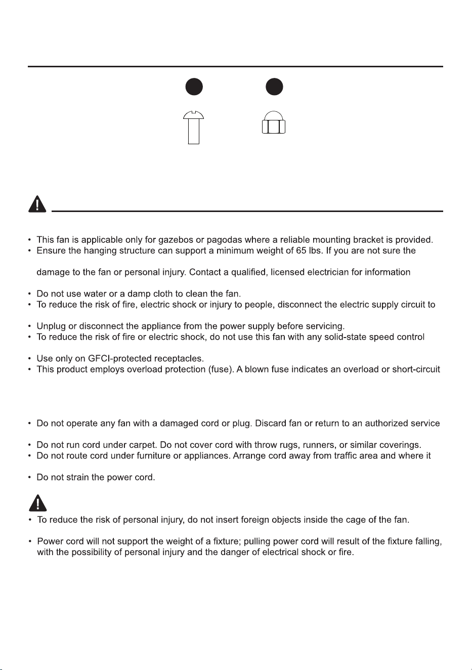
HARDWARE CONTENTS (shown actual size)
SAFETY INFORMATION
READ AND SAVE THESE INSTRUCTION
hanging structure can support the weight, do not attempt to install this fan as it may fall and cause
regarding proper mounting methods in your area.
the fan before installing, cleaning and servicing the item.
device.
situation. If the fuse blows, unplug the product from the outlet. Replace the fuse as per the user
servicing instructions (follow product marking for proper fuse rating) and check the product. If the
replacement fuse blows, a short circuit may have happened and the product should be discarded or
returned to an authorized service facility for examination and/or repair.
facility for examination and/or repair.
will not be tripped over.
Set Screw
Qty. 1
Acorn Nut
Qty. 1
AA BB
WARNING
Do not damage or deform the cage of the fan.
5
PREPARATION
Before beginning assembly of the product, make sure all parts are present. Compare parts with
package contents list and hardware contents list. If any part is missing or damaged, do not attempt to
assemble the product.
Estimated Assembly Time: 45 minutes
Tools Required for Assembly (not included): Philips Screwdriver, Step Ladder, Tape and Pliers.
IMPORTANT: To avoid over-pull to damage the wire and plug, turn off circuit breakers and wall
switch to the fan supply line leads.
ASSEMBLY INSTRUCTIONS
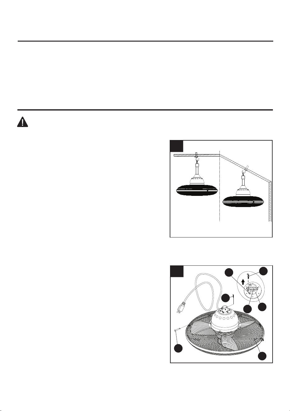
1. Choose the desired mounting method:
A. Standard Mounting:
Note: For a ceiling higher than 8 ft., you can
purchase an extension downrod.
B.
Angle Mounting: Angle mounting is used for
vaulted or angled ceilings.
Note: The preferred mounting method is to gazebos
or pagodas. However, other mounting methods
are also supported. For example, the fan can be
mounted on a drywall, provided the surface supports
a minimum weight of 65 lbs.
1
A
B
2. Remove the clip (H) and cross pin (G) from the
coupling (F) on the motor body (D). Loosen the
coupling screws (I) on the motor body (D).
2
H
F
D
G
I
H
G
6
ASSEMBLY INSTRUCTIONS
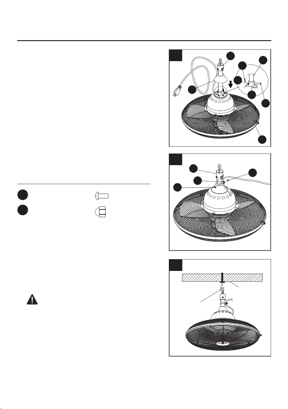
3. Insert downrod assembly (A) through coupling cover
(B) into coupling (F). Make sure to align the hole in
downrod assembly (A) with the hole in coupling (F).
Install cross pin (G) through coupling (F) and downrod
assembly (A). Insert clip (H) into cross pin (G) until it
snaps into place. Tighten coupling screws (I) and slide
the coupling cover (B) onto the motor body (D).
3
4.
Secure the wire from motor body (D) to the downrod
assembly (A) with rod clip (C). Use set screw (AA) and
acorn nut (BB) to tighten rod clip (C).
4
Hardware Used
Set Screw
Acorn Nut
x 1
x 1
AA
BB
A
A
BB
C
AA
G
B
D
A
H
I
F
5. For ceiling-mount installations, attach a standard
mounting bracket (not included) to a ceiling or outdoor
gazebo/pagoda per the bracket instructions. Then,
attach the fan assembly to the mounting bracket from
the spring clip on downrod assembly (A).
5
W
ARNING:
Ensure the hanging structure
can support a minimum weight of 65 Ibs and allow
enough depth for safety mounting. If you are not
sure the hanging structure can support the weight,
do not attempt to install this fan as it may fall and
cause damage to the fan or personal injury
.
Bracket
Spring Clip
7
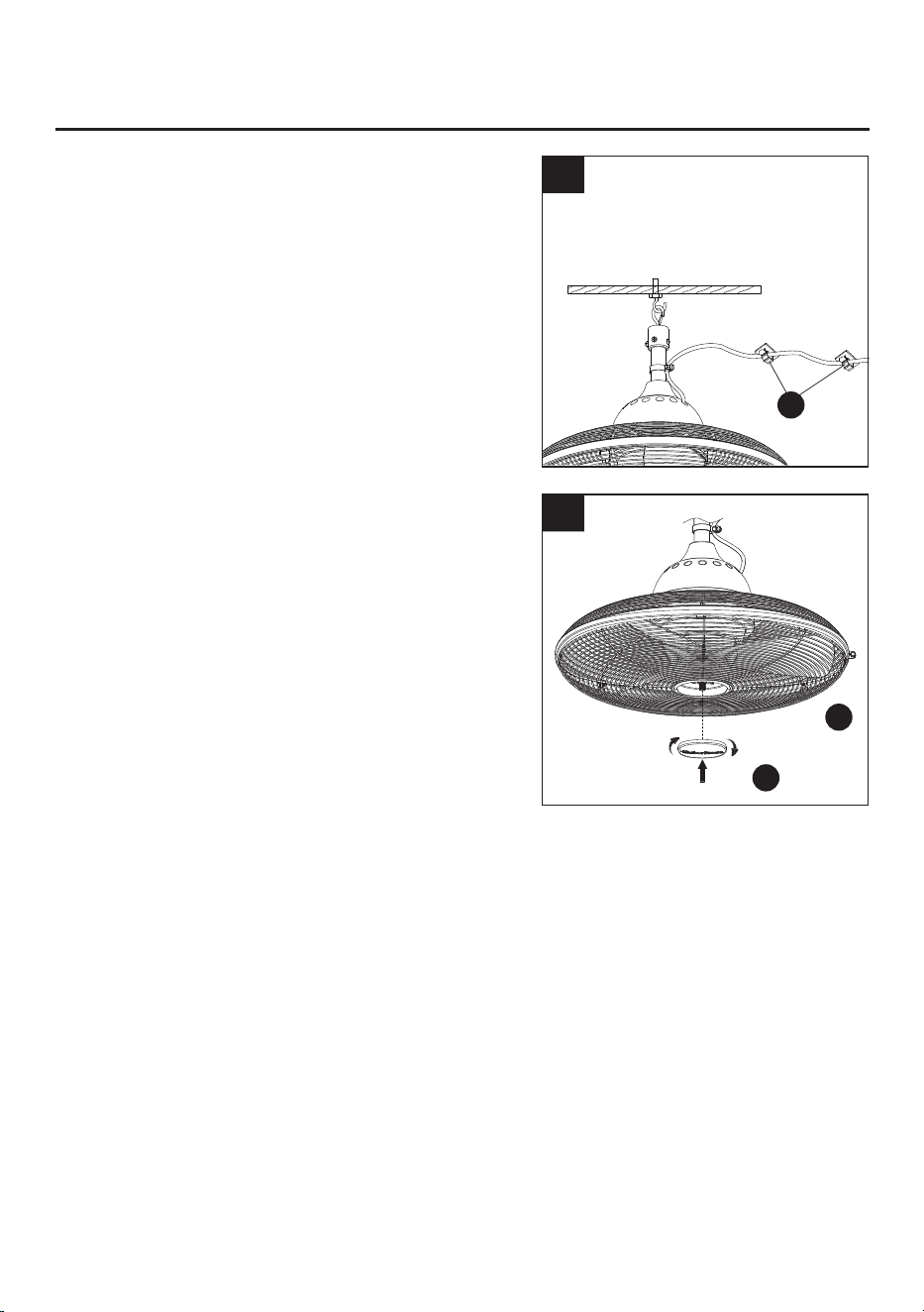
6.
Peel the back
ing of
f the adhesive tape stripes
on the
bottom of the wire clips (E).
Attach the wire clips (E)
as needed to the wall or ceiling and press gently
. Clip
the power cord to the wire clips (E). Plug the power
cord into a ground 3-prong outlet. Once you restore
power to the house, the fan is ready to use.
6
ASSEMBLY INSTRUCTIONS
E
7.
Tighten the decorative cover (J) onto the Motor Body
(D) in clockwise direction.
7
J
D
8
1
2
3
OPERATIING INSTRUCTIONS
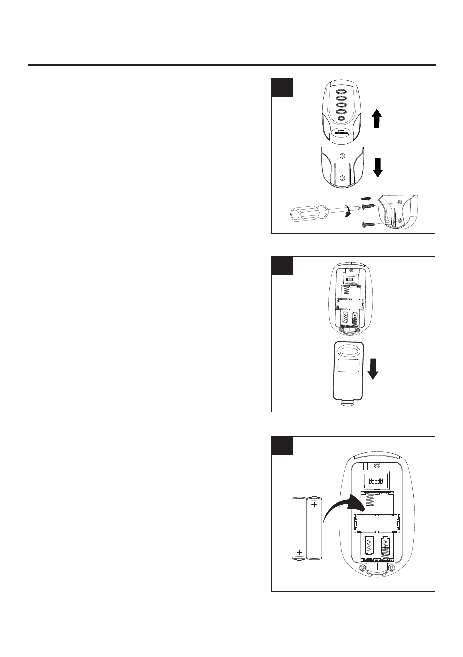
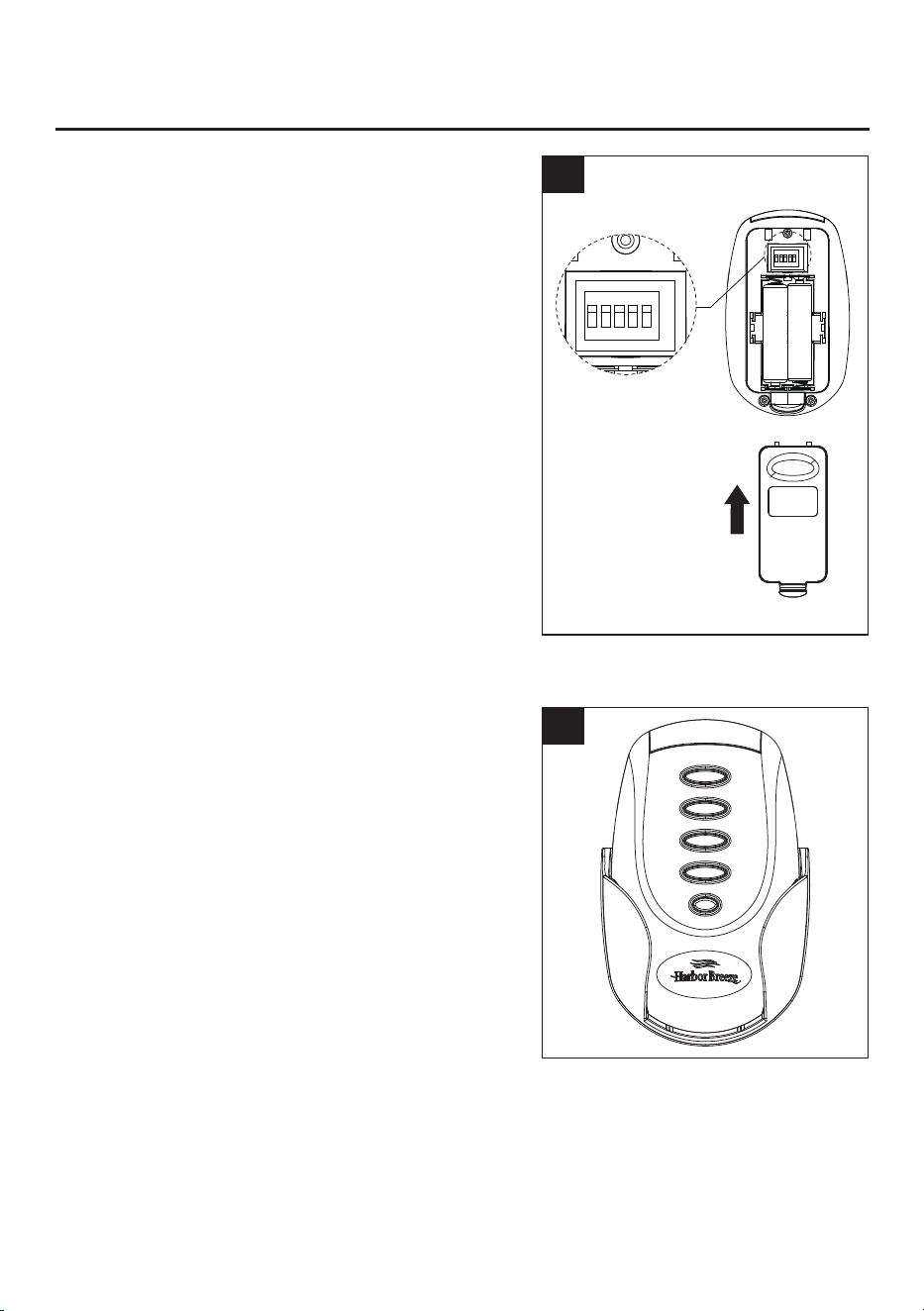
2. Open the battery cover.
3. To make fan operational, install two 1.5V AAA batteries
(included). Replace the battery cover.
NOTE: This remote control uses two 1.5V AAA batteries.
Replace batteries with the correct size and type of battery.
Clean the battery contacts and area inside the device
prior to installing new batteries. Ensure the batteries are
installed correctly with regard to the polarity ( + and -).
NOTE: If not used for long periods of time, remove
battery to prevent damage to transmitter. Store the
remote control away from excessive heat and humidity.
1.
Slide the transmitter out of the transmitter holder. Select
a location to install your transmitter holder. Attach the
transmitter holder with screws provided.
ON
ECE
1 2 3 4 5
ON
ECE
1 2 3 4 5
O
FF
HI
M
ED
L
O
4.
4
OPERATIING INSTRUCTIONS
9
ON
1
2
3
4
5
ON
1
2
3
4
5
The remote unit has 32 different code combinations,
each transmitter of this remote control carries a unique
ID code to facilitate communication between paired
devices. The ID code is set by factory and is not user
changeable. However, you will be required to perform
an “ID code learning” process manually under these
circumstances.
• If you have multiple fans installed within a close
proximity and want to control all fans NOT using the
same remote transmitter.
NOTE: Each fan requires its own receiver.
• When your remote control is not responding (make
sure battery is not flat).
• After you have replaced a faulty transmitter or
receiver with a new one.
Otherwise the remote control will not work.
To perform this process manually, follow steps below:
Simply change the combination code by sliding dip
switches in the remote. Press the “ OFF” button for 5
seconds within 1 minute after restoring power to the
fan, the fan will beep five times . This indicate the
code learning process has been completed.
5.
5
Special function! Start the fan without transmitter in
the following way:
Flip the power switch 3 times within 8 seconds to
obtain High speed
Flip the power switch 4 times within 8 seconds to
obtain Medium speed
Flip the power switch 5 times within 8 seconds to
obtain Low speed
OFF
HI
MED
LO
Remote functions:
OFF: Turns off the fan
HI: High speed
MED: Medium speed
LO: Low speed, Press the button for 5 seconds to turn
ON/OFF the buzzer
No function
①
②
③
④
⑤
①
②
③
④
⑤
10
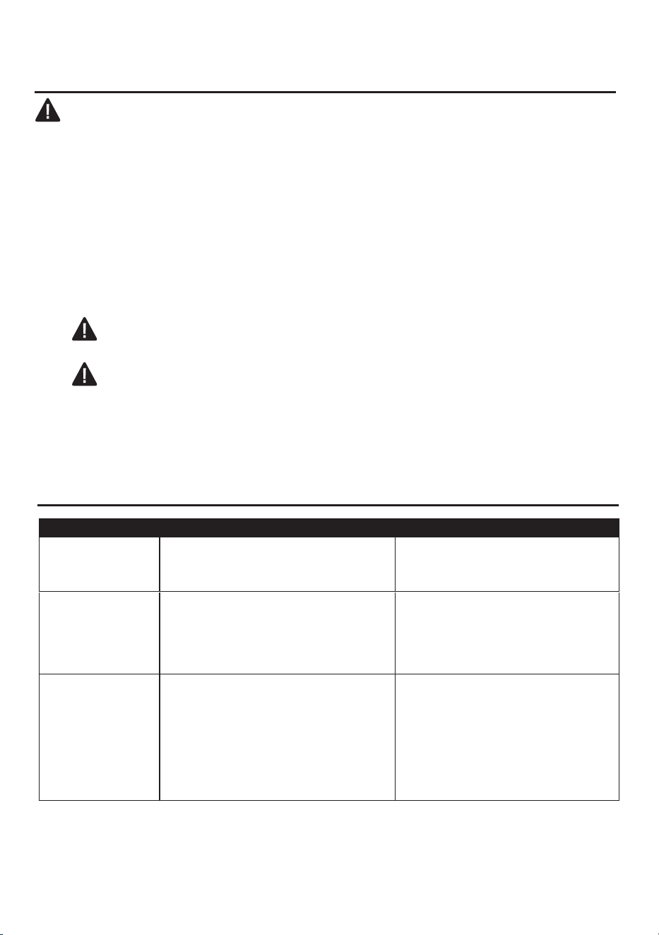
• Clean fan housing with only a soft brush or lint-free cloth to avoid scratching the finish. Clean
blades with a lint-free cloth.
• This product employs overload protection (fuse). A blown fuse indicates an overload or short-circuit
situation. If the fuse blows, unplug the product from the outlet and replace the fuse as below:
1) Grab the plug and remove it from the receptacle or other outlet device. Do not unplug by pulling
on cord.
2) Slide open fuse access cover on top of attachment plug toward blades.
3) Remove the fuse carefully.
4) Replace fuse.
CAUTION: Risk of fire. Use only 5-amp, 125-volt fuses.
5) Slide closed the fuse access cover on top of attachment plug.
CAUTION: Risk of fire. Do NOT replace the attachment plug, as it contains a safety device
IMPORTANT: Shut off the main power supply before beginning any maintenance. Do not use
water or a damp cloth to clean the ceiling fan.
CARE AND MAINTENANCE
(fuse) that should not be removed. Discard the product if the attachment plug is damaged.
PROBLEM POSSIBLE CAUSE CORRECTIVE ACTION
1. Fan does not
move
1. Power is off or fuse is blown.
2. Bad wire connection.
1. Turn power on or check fuse.
2.
Turn power off. call customer
service to check all connections.
2. Noisy operation 1. Blades are loose.
2. Blade is cracked.
3. Non-approved speed control.
1. Tighten all blade screws.
2. Replace blades (call customer
service for special replacement).
3. Replace with an approved speed
control device.
3. Excessive
wobbling
1. Unbalanced blades.
2. Blades are loose.
3. Fan not securely mounted.
4. Fan too close to vaulted ceiling.
1. Switch with blade from opposite
side.
2. Tighten all blade screws.
3. Turn off power. Carefully loosen
canopy, and remount securely.
4. Lower or move fan. Extension
downrods may be offered (call
customer service).
TROUBLESHOOTING

11
The manufacturer warrants this fan to be free from defects in work
manship and material present at
time of shipment from the factory for life (with limitations) from the date of purchase.
This warranty
applies only to the original purchaser. The manufacturer agrees to correct such defect at no charge
or, at our option, replace the ceiling fan with a comparable or superior model.
To obtain warranty service, present a copy of your sales receipt as proof of purchase. All cost of
removal and reinstallation are the expressed responsibility of the purchaser. Any damage to the
ceiling fan by accident, misuse or improper installation, or by affixing accessories not produced by
this warranty, are at the purchaser’s own responsibility. The manufacturer assumes no responsibility
whatsoever for fan installation during the limited lifetime warranty. Any service performed by an
unauthorized person will render the warranty invalid.
Due to varying climatic conditions, this warranty does not cover changes in brass finish, rusting,
pitting, tarnishing, corroding or peeling. Brass finish fans maintain their beauty when protected from
varying weather conditions.
Any replacement of defective parts for the ceiling fan must be reported within the first year from the
date of purchase. For the balance of the warranty, call our customer service department at
888 - 251 - 1003 for return authorization and shipping instructions so that we may repair or replace the
ceiling fan. Any fan or parts returned improperly packaged is the sole responsibility of the purchaser.
There is no further expressed warranty. The manufacturer disclaims any and all implied warranties.
The duration of any implied warranty which cannot be disclaimed is limited to the lifetime limited
period as specified in our warranty. The manufacturer shall not be liable for incidental, consequential
or special damages arising at or in connection with product use or performance except as may
otherwise be accorded by law. This warranty gives you specific legal rights, and you also have other
rights which vary from state to state. This warranty supersedes all prior warranties.
Note: A small amount of “wobble” is normal and should not be considered a defect.
This device complies with Part 15 of the FCC Rules.
Operation is subject to the following two conditions:
(1) This device may not cause harmful interference, and (2) this device must accept any interference
received, including interference that may cause undesired operation. Please note that changes or
modifications not expressly approved by the party responsible for compliance could void the user's
authority to operate the equipment.
Note: The remote control has been tested and found to comply with the limits for Class B digital device,
pursuant to part 15 of the FCC Rules. These limits are designed to provide reasonable protection
against harmful interference in a residential installation.
The remote control generates, uses and can radiate radio frequency energy and, if not installed and
used in accordance with the instructions, may cause harmful interference to radio or television
reception, which can be determined by turning the equipment off and on, the user is encouraged to
try to correct the interference by one or more of the following measures:
- Reorient or relocate the receiving antenna.
- Increase the separation between the equipment and the receiver.
- Connect the equipment into an outlet on a circuit different from that to which the receiver is
connected.
Consult the dealer or an experienced radio/TV technician for help.
LIMITED LIFETIME WARRANTY
FCC WARNING
12
OFF
HI
MED
LO
x2
x2
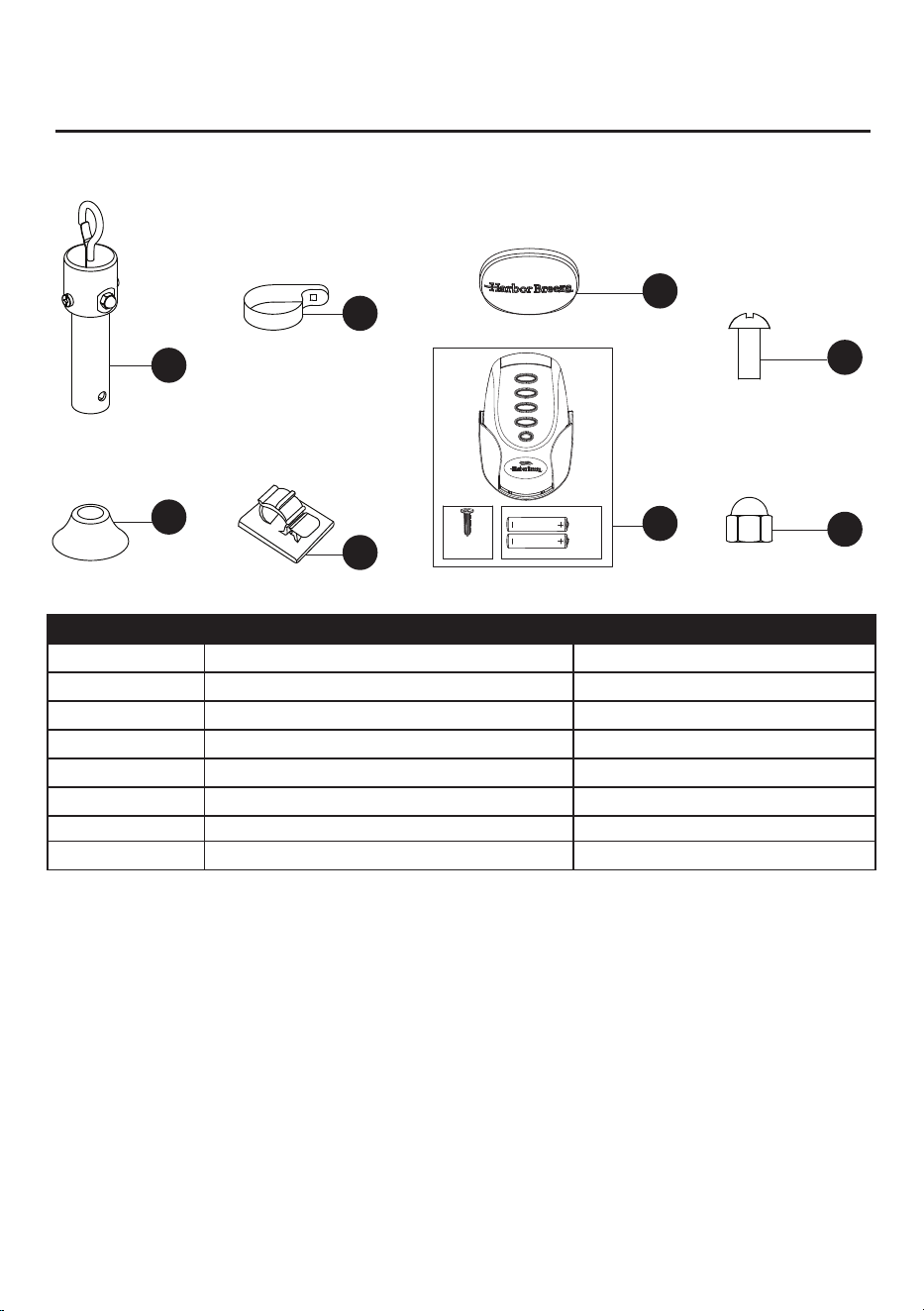
PART DESCRIPTION PART #
A Downrod Assembly
A103-0230406
B Coupling Cover
A106-0108406
C Rod Clip B170-0010005
E
J
K
B166-0384036
A183-B023406
A137-C002036
AA
B166-0814070
BB
Wire Clip
Decorative cover
Remote Unit
Set Screw
Acorn nut
B166-0813070
For replacement parts, call our customer service department at 888-251-1003, 8 a.m. - 8 p.m., EST,
Monday - Sunday. You could also contact us at [email protected].
Printed in China
A
AA
J
K
BB
B
C
E
REPLACEMENT PARTS LIST