
P250096
Ceiling Fan Installation Manual
93164932_A

Date Purch as ed
Sto re Pu rchas ed
Model No.
Serial No.
Vend or No.
126900
P250096
Limited Lifetime Warranty
Progress Lighting fan motors are warranted to the original purchaser to be free of electrical and/or mechanical defects for so
long as the original purchaser owns the fan. Pull chain switches, reverse switches, capacitors and metal finishes are warranted to
be free from defects in materials or workmanship for a period of 1 year from the date of purchase. Warping of wooden or plastic
blades is not covered by this warranty nor is corrosion and/or deterioration of any finishes for fans installed within ten miles of
any sea coast. Extended warranties for ENERGY STAR
®
qualified products may apply.
Progress Lighting ceiling fans with built-in LED light sources, when properly installed and under normal conditions of use, are
warranted to be free from defects in material and workmanship which cause the light sources to fail to operate in accordance
with the specifications for (i) five (5) years from the date of purchase on the LED Light modules and electrical components for
fans used in single family residences, and (ii) three (3) years from the date of purchase on the LED Light modules and electrical
components for fans used in multi-family or commercial applications. LED bulbs supplied by Progress Lighting carry no
warranty other than manufacturer’s warranty. Non-LED bulbs carry no warranty.
With proof of purchase, the original purchaser may return the defective fan to the place of purchase during the first 30 days for
replacement. After 30 days, the original purchaser MUST contact Progress Lighting at (864) 678-1000 for repair or replacement
which shall be determined in Progress Lighting’s sole discretion and shall be purchaser’s sole and exclusive remedy.
Labor and Shipping Excluded. This warranty does not cover any costs or fees associated with the labor (including, but not
limited to, electrician’s fees) required to install, remove, or replace a fan or any fan parts.
This warranty shall not apply to any loss or damage resulting from (i) normal wear and tear or alteration, misuse, abuse or
neglect, or (ii) improper installation, operation, repair or maintenance by original purchaser or a third party, including without
limitation improper voltage supply or power surge, use of improper parts or accessories, unauthorized repair (made or
attempted) or failure to provide maintenance to the fan.
THE FOREGOING WARRANTIES STATE PROGRESS LIGHTING’S ENTIRE WARRANTY OBLIGATION AND
ORIGINAL PURCHASER’S SOLE AND EXCLUSIVE REMEDY RELATED TO SUCH PRODUCTS. PROGRESS
LIGHTING IS NOT RESPONSIBLE FOR DAMAGES (INCLUDING INDIRECT, SPECIAL, INCIDENTIAL OR
CONSEQUENTIAL), DUE TO PRODUCT FAILURE, WHETHER ARISING OUT OF BREACH OF WARRANTY,
BREACH OF CONTRACT, OR OTHERWISE. THIS WARRANTY IS GIVEN IN LIEU OF ALL OTHER WARRANTIES,
WHETHER EXPRESSED OR IMPLIED, INCLUDING THOSE OF MERCHANTABILITY, FITNESS FOR A PARTICULAR
PURPOSE OR NONINFRINGEMENT.
Some states do not allow limitations on how long an implied warranty lasts or the exclusion or limitations of incidental or
consequential damages, so the above limitations and exclusions may not apply to you. This warranty gives you specific rights
and you may have other rights which vary from state to state.
UPC
785247266678
785247266661
785247266654

Table of Contents
Safety Rules.....................................................................................................................................................................................
Unpacking Your Fan .......................................................................................................................................................................
Installing Your Fan .........................................................................................................................................................................
Operating Your Transmitter ...........................................................................................................................................................
1.
2.
3.
8.
Care of Your Fan ............................................................................................................................................................................
Troubleshooting ............................................................................................................................................................................
Specifications ................................................................................................................................................................................
10.
11.
9.
1. Safety Rules
1. To reduce the risk of electric shock, ensure electricity has been turned off
at the circuit breaker or fuse box before beginning.
2. All wiring must be in accordance with the National Electrical Code and
local electrical codes. Electrical installation should be performed by a
qualified licensed electrician.
3. WARNING: To reduce the risk of electrical shock and fire, do not use
this fan with any solid-state fan speed control device.
4. WARNING: To reduce the risk of fire, electric shock, or personal injury,
mount to outlet box marked "Acceptable for Fan Support of 15.9 kg (35 lbs.)
Or Less" and use mounting screws provided with the outlet box. Most outlet
boxes commonly used for the support of light fixtures are not acceptable for
fan support and may need to be replaced. Due to the complexity of the
installation of this fan, a qualified licensed electrician is strongly
recommended.
WARNING
TO REDUCE THE RISK OF FIRE, ELECTRIC SHOCK OR PERSONAL
INJURY, MOUNT FAN TO OUTLET BOX MARKED ACCEPTABLE FOR
FAN SUPPORT.
5. The outlet box and support structure must be securely mounted and
capable of reliably supporting a minimum of 35 lbs (15.9 kg) or less.
Use only UL-listed outlet boxes marked FOR FAN SUPPORT.
6. The fan must be mounted with a minimum of 7 ft (2.1m) clearance from
the trailing edge of the blades to the floor.
7. To operate the reverse function on this fan, slide the reverse switch to the
opposite position. Do not operate reverse switch while fan blades are in
motion. Fan must be turned off and blades stopped before reversing blade
direction.
8. Avoid placing objects in the path of the blades.
9. To avoid personal injury or damage to the fan and other items, be
cautious when working around or cleaning the fan.
10. Do not use water or detergents when cleaning the fan or fan blades. A
dry dust cloth or lightly dampened cloth will be suitable for most
cleaning.
11. After making electrical connections, spliced conductors should be
turned upward and pushed carefully up into the outlet box. The wires
should be spread apart with the grounded conductor and the
equipment-groundi
ng conductor on one side of the outlet box.
12. Electrical diagrams are for reference only. Light kits that are not packed
with the fan must be UL Listed and marked suitable for use with the
model fan you are installing. Switches must be UL General Use
Switches. Refer to the Instructions packaged with the light kits
NOTE
READ AND SAVE ALL INSTRUCTIONS!
WARNING
TO REDUCE THE RISK OF PERSONAL INJURY, DO NOT BEND THE
BLADE ARMS (ALSO REFERRED TO AS BRACKETS) DURING
ASSEMBLY OR AFTER INSTALLATION. DO NOT INSERT OBJECTS IN
THE PATH OF THE BLADES.
Unpacking Your Fan 2.
1
2
3
5
7
9
10
8
6
4
11
a
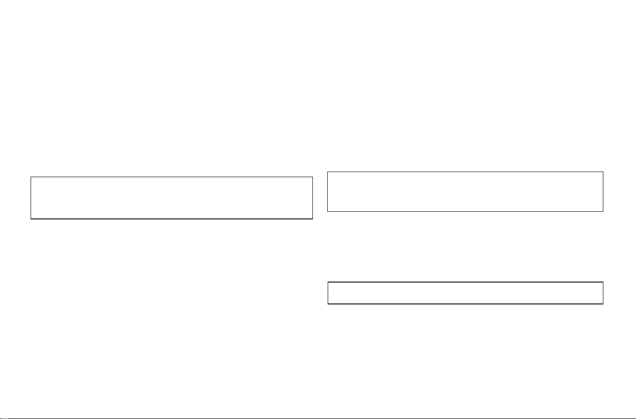
Unpack your fan and check the contents. You should have the following items:
1.Hanger bracket
2.Canopy
3.Canopy cover
4.Ball/downrod assembly
5.Coupling cover
6.Fan motor assembly
7.Decorative cover
8.Transmitter incl. holder + 1 mounting screw
9.Receiver with 5 wire nuts
10.12V 23A battery
11.Loose parts bag containing:
a.Mounting hardware
Wire nuts (4)
ON
ON
1 2 3 4
Tools Required
Phillips screw driver, straight slot screw driver,
adjustable wrench, step ladder, and wire cutters.
Mounting Options
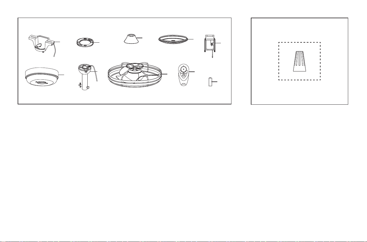
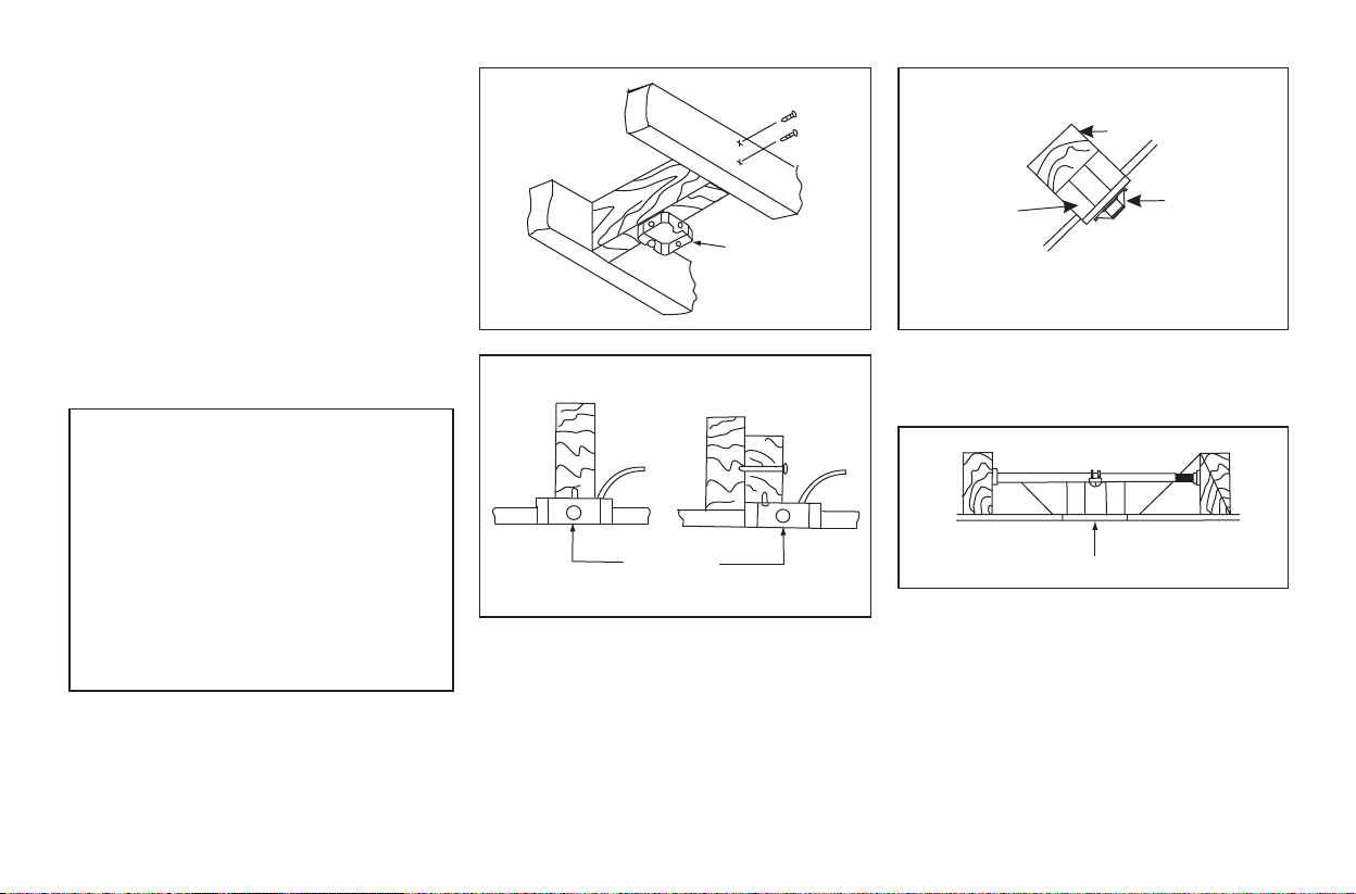
If there isn't an existing UL listed mounting box,
then read the following instructions. Disconnect
the power by removing fuses or turning off
circuit breakers.
Secure the outlet box directly to the building
structure. Useappropriate fasteners and building
materials. The outlet box and its support must be
able to fully support the moving weight of the
fan (at least 35 lbs). Do not use plastic outlet
boxes.
3. Installing Your Fan
WARNING
TO REDUCE THE RISK OF FIRE, ELECTRIC
SHOCK, OR OTHER PERSONAL INJURY,
MOUNT FAN ONLY TO AN OUTLET BOX
MARKED ACCEPTABLE FOR FAN SUPPORT
AND USE THE MOUNTING SCREWS
PROVIDED WITH THE OUTLET BOX. OUTLET
BOXES COMMONLY USED FOR THE
SUPPORT OF LIGHTING FIXTURES MAY NOT
BE ACCEPTABLE FOR FAN SUPPORT AND
MAY NEED TO BE REPLACED. CONSULT A
QUALIFIED ELECTRICIAN IF IN DOUBT.
Figure 1
Outlet box
Figure 2
Outlet box
Figure 3
Angled ceiling
maximum
25 angle
Recessed
outlet box
Provide strong support
Ceiling
hanger
bracket
Figure 4
Outlet box
Note: You may need a longer downrod to
maintain proper blade clearance when installing
on a steep, sloped ceiling.
To hang your fan where there is an existing
fixture but no ceiling joist, you may need an
installation hanger bar as shown in Figure 4
(available at your Progress Lighting Retailer).
4.
Hanging the Fan
WARNING
FAILURE TO PROPERLY INSTALL
LOCK PIN AS NOTED IN STEP 5
COULD RESULT IN FAN LOOSENING AND
POSSIBLY FALLING.
Ceiling hanger
bracket
UL Listed
electrical box
Washers
Mounting screws
(supplied with
electrical box)
120V wires
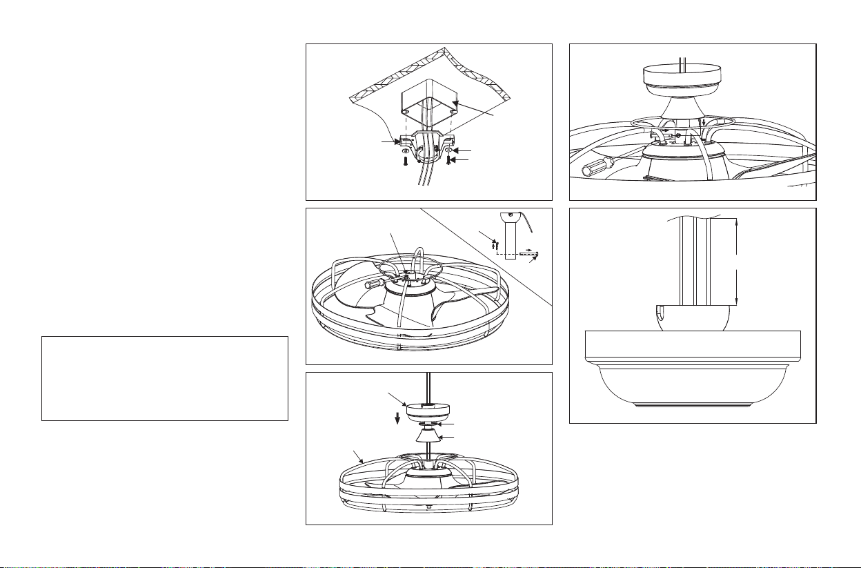
Figure 5
Figure 6
Figure 8
Figure 9
Figure 7
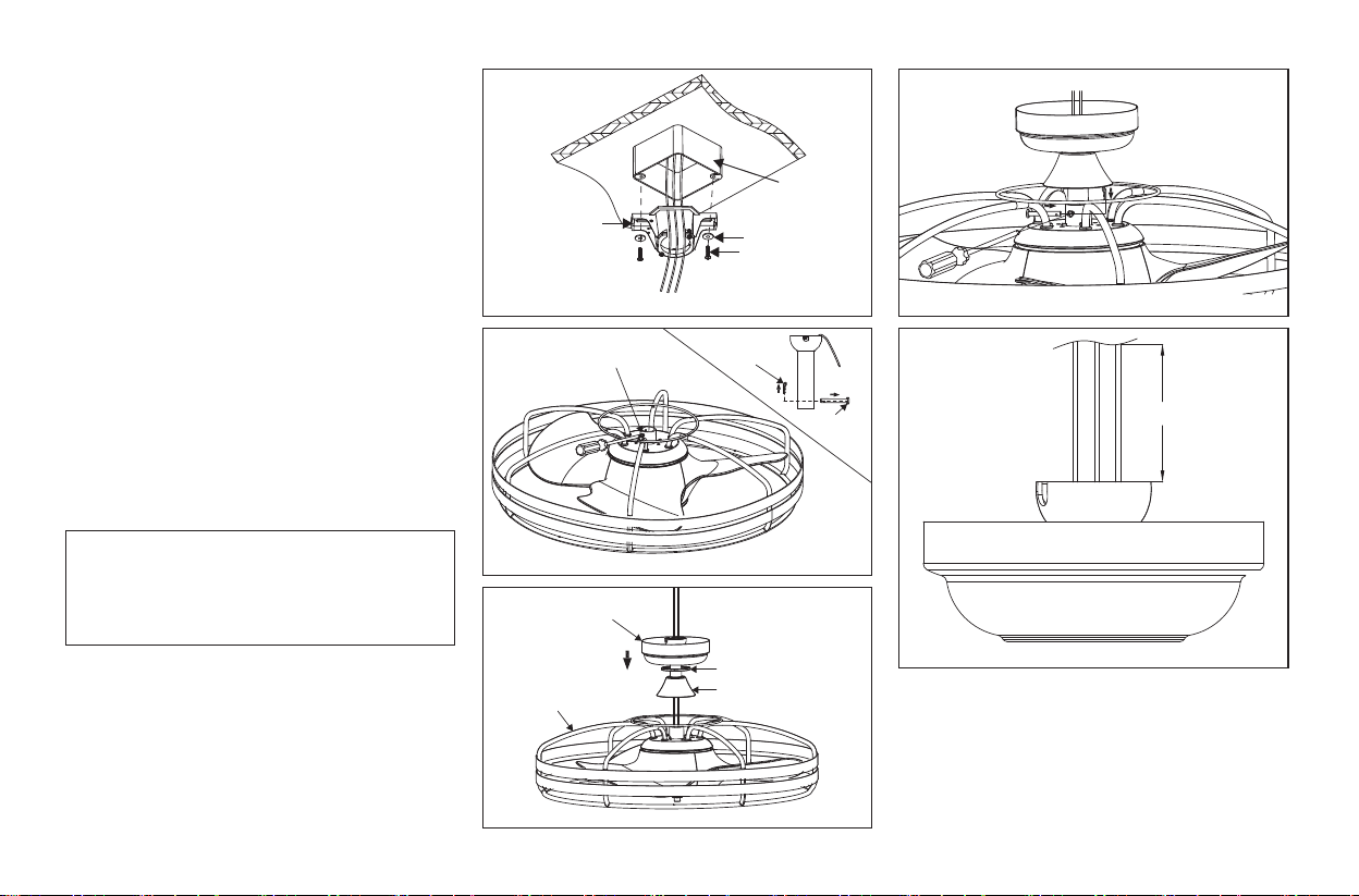
Step 5. Carefully insert the hanger pin through
the holes in the collar and downrod. Be careful
not to jam the pin against the wiring inside the
downrod. Insert the lock pin through the hole near
the end of the hanger pin until it snaps into its
locked position, and tighten set screws as shown
in Figure 8.
Step 6. Cut off excess fixture wires leaving
approximately 6 to 9 inches above top of hanger
ball/downrod assembly. (Figure 9)
REMEMBER to turn off the power. Follow the
steps below to hang your fan properly:
Step 1. Pass the 120-volt supply wires through
the center hole in the ceiling hanger bracket as
shown in Fig. 5.
Step 2. Secure the hanger bracket to the ceiling
outlet box with the screws and washers provided
with your outlet box.
Step 3. Remove the hanger pin, lock pin and set
screws from the top of the motor assembly. (Fig. 6)
Step 4. Route wires exiting from the top of the fan
motor through the coupling cover, canopy cover,
canopy and then through the downrod. (Fig. 7)
6 to 9in
Set screw
Canopy
Canopy cover
Coupling cover
Fan motor
assembly
Lock pin
Hanger
pin

5.
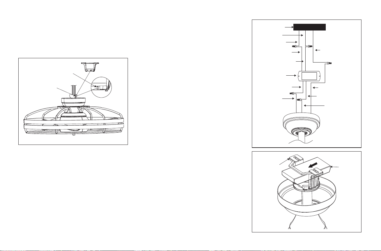
Step 7. Carefully lift the assembly and rest the
hanger ball of downrod assembly on the hanger
bracket attached to the outlet box. Be sure the
groove in the hanger ball is lined up with the tab
on the hanger bracket. (Fig.10)
WARNING: Fan must be installed at a maximum
distance of 20 feet from the transmitting unit for
proper signal transmission between the
transmitting unit and the fan’s receiving unit. If
you feel you do not have enough electrical wiring
knowledge or experience, have your fan installed
by a licensed electrician.
Step 1. Motor to receiver electrical connections:
Connect the black wire from the fan to the black
wire from the receiver. Connect the white wire
from the fan to the white wire from the receiver.
(Fig.11)
Step 2. Receiver to house supply wires electrical
connections: Connect the black (hot) wire from
the ceiling to the black wire marked "AC IN L"
from the receiver. Connect the white (neutral)
wire from the ceiling to the white wire marked
"AC IN N" from the receiver. (Fig.11)
Step 3. Ground wires connections: Connect the
GROUND wire from the house to the GREEN
wires from the motor assembly and mounting
plate. (Fig.11)
Secure all wire connections with the plastic wire
nuts provided.
Step 4. Place the receiver into the hanger bracket
and keep flat in opposition of ceiling. (Fig. 12)
WARNING: To avoid possible electrical shock,
be sure electricity is turned off at the main fuse
box before wiring.
Make the Electric
Connections
Figure 10
Figure 11
Figure 12
Ground wire
White (AC IN N)
Receiver
Black(TO MOTOR L)
Black
White(TO MOTOR N)
White
Tab
Groove
Hanger
bracket
Receiver
Black(AC IN L)
Ground wire
White
Outlex box
Black

6.
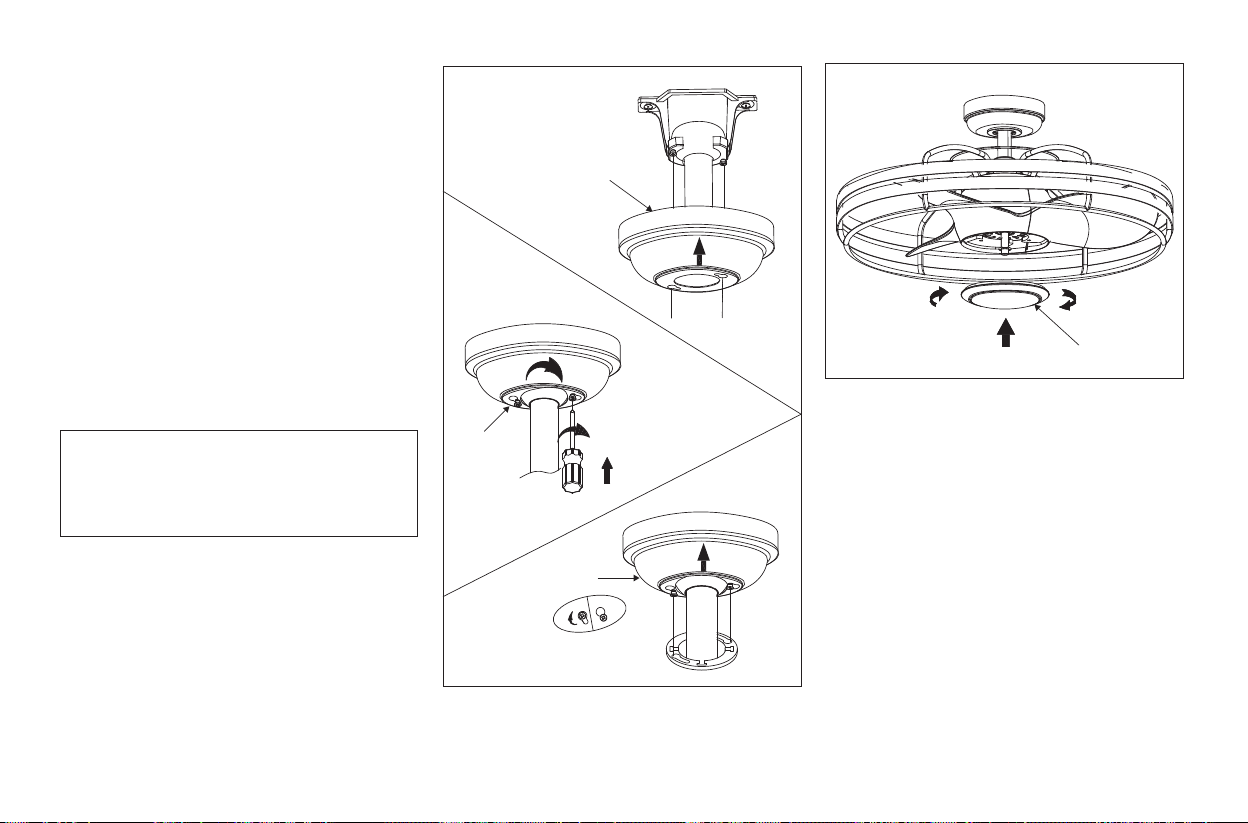
Step 1. Tuck connections neatly into ceiling
outlet box.
Step 2. Slide the canopy up to mounting bracket
and place the key hole on the canopy over the
screw on the mounting bracket, turn canopy until
it locks in place at the narrow section of the key
holes. (Fig. 13)
Step 3. Align the circular hole on canopy with the
remaining hole on the mounting bracket, secure
by tightening the two set screws. Note: Adjust the
canopy screws as necessary until the canopy and
canopy cover are snug.
Step 4. Secure the decorative cover to fan motor
assembly by twisting in a clockwise direction. Do
not over-tighten. (Figure 14)
Finishing the Installation
WARNING
Make sure the notch on the hanging bracket properly
sits in the groove in the hanger ball before attaching
the canopy to the bracket by turning the housing until
it drops into place.
Figure 13
Figure 14
Decorative cover
Decorative
cover
Canopy
Canopy
7.
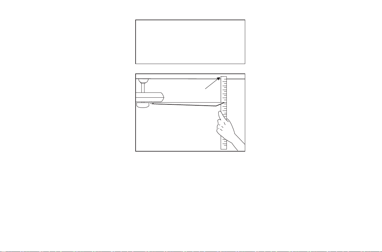
All blades are grouped by weight. Because
natural woods vary in density, the fan may
wobble even though the blades are weighed
equally.
The following procedure should correct most fan
wobbling problems. Check after each step.
1. Check that all blade and blade arm screws are
secure.
2. Most fan wobbling problems are caused when
blade levels are unequal. Check this level by
selecting a point on the ceiling above the tip of
one of the blades. Measure this distance as shown
in Figure 15. Rotate the fan until the next blade is
positioned for measurement. Repeat for each
blade. The distance deviation should be equal
within 1/8".
3. If the blade wobble is still noticeable,
interchanging two adjacent (side by side) blades
can redistribute the weight and possibly result in
smoother operation.
WARNING
TO REDUCE THE RISK OF PERSONAL
INJURY, DO NOT BEND THE BLADE
HOLDERS WHILE INSTALLING,
BALANCING THE BLADES, OR CLEANING
THE FAN. DO NOT INSERT FOREIGN
OBJECTS BETWEEN ROTATING FAN
BLADES.
Touching
ceiling
Figure 15
Blade Balancing
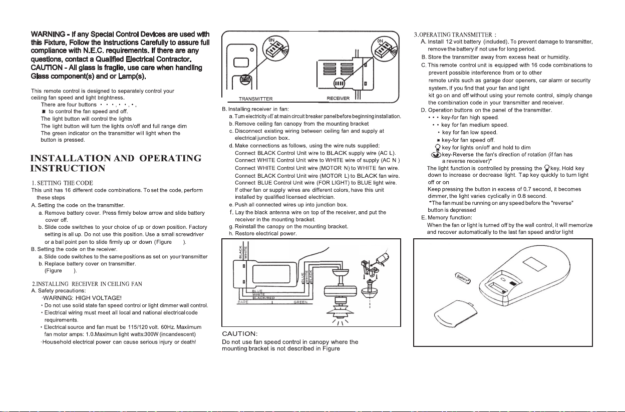
Figure 17
Operating Your Transmitter 8.
17.
16-1
16-2
CODE
SWITCHES
(FIG 16-1)
CODE
SWITCHES
(FIG 16-2)
AC
SUPPLY
RECEIVER
Figure 18
9.
Care of Your Fan
Speed settings for warm or cool weather depend
on factors such as the room size, ceiling height,
number of fans and so on.
NOTE: to operate the reverse function on this
fan, slide the reverse switch to the opposite
position. Do not operate reverse switch while fan
blades are in motion. Fan must be turned off and
blades stopped before reversing blade direction.
Warm weather - (Forward) A downward airflow
creates a cooling effect as shown in Fig. 19. This
allows you to set your air conditioner on a warmer
setting without affecting your comfort.
Cool weather - (Reverse) An upward airflow
moves warm air off the ceiling area as shown in
Fig. 20. This allows you to set your heating unit
on a cooler setting without affecting your
comfort.
Here are some suggestions to help you maintain
your fan.
1. Because of the fan's natural movement, some
connections may become loose. Check the
support connections, brackets, and blade
attachments twice a year. Make sure they are
secure. (It is not necessary to remove fan from
ceiling.)
2. Clean your fan periodically to help maintain its
new appearance over the years. Use only a soft
brush or lint-free cloth to avoid scratching the
finish. The plating is sealed with a lacquer to
minimize discoloration or tarnishing. Do not use
water when cleaning. This could damage the
motor, or the wood, or possibly cause an electrical
shock.
3. You can apply a light coat of furniture polish to
the wood blades for additional protection and
enhanced beauty. Cover small scratches with a
light application of shoe polish.
4. There is no need to oil your fan. The motor
has permanently lubricated bearings.
Figure 19
Figure 20
IMPORTANT
MAKE SURE THE POWER IS OFF AT THE
ELECTRICAL PANEL BOX BEFORE YOU
ATTEMPT ANY REPAIRS. REFER TO THE
SECTION "MAKING ELECTRICAL
CONNECTIONS"
Reverse
Switch

Troubleshooting
10.
Solution
1. Check circuit fuses or breakers.
2. Check line wire connections to the fan and switch wire connections in the switch housing.
CAUTION: Make sure main power is off.
1. Make sure all motor housing screws are snug.
2. Make sure the screws that attach the fan blade bracket to the motor hub is tight.
3. Make sure wire nut connections are not rubbing against each other or the interior wall of the switch housing.
CAUTION: Make sure main power is off.
4. Allow a 24-hour "breaking-in" period. Most noise associated with a new fan disappear during this time.
5. If using an optional light kit, make sure the screws securing the glassware are tight. Check that light bulb is also secure.
6. Make sure the upper canopy is a short distance from the ceiling. It should not touch the ceiling.
1. Do not connect the fan with wall mounted variable speed control (s).
Remote control
malfunction
Problem
Fan will not start.
Fan sounds noisy.
11.
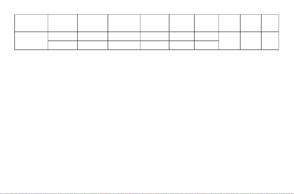
Specifications
15.87 20.72 4.63'
52"
These are approximate measures. They do not include Amps and Wattage used by the light kit.
©2022 Progress Lighting, Inc.
701 Millennium Blvd.,
Greenville, SC 29607
All Rights Reserved
135
288
672.90
1506.23
lbs lbs
Fan Size
VoltsSpeed
Amps
Watts
RPM
CFM
N.W. G.W. C.F.
Low
High
5.39
14.97
0.09
0.13
120
120
P250096
Manual de instalación del ventilador de techo
93164932_A
126900
P250096
Garantía Limitada Vitalicia
UPC
785247266678
785247266661
785247266654
Fecha de compra
Compra realizada
en la tienda
Nº. de modelo
Nº. de serie.
N°. de proveedor
Los motores de ventilador tienen una garantía sin defectos eléctricos y/o mecánicos para el comprador original durante el tiempo que
el comprador original sea propietario del ventilador. Los interruptores de cordón o cadena, los interruptores de inversión, los
condensadores y los acabados metálicos están garantizados como libres de defectos en los materiales o en la mano de obra durante un
período de 1 año a partir de la fecha de compra. La deformación de las aspas de madera o plástico no está cubierta por esta garantía, ni
tampoco la corrosión y/o el deterioro de los acabados de los ventiladores instalados a menos de diez millas de cualquier costa marítima.
Es posible que se apliquen garantías ampliadas para los productos calificados como ENERGY STAR®.
Los ventiladores Progress Lighting de techo con fuentes de luz LED incorporadas, cuando se instalan correctamente y en condiciones
normales de uso, están garantizados contra defectos de materiales y mano de obra que hagan que las fuentes de luz no funcionen de
acuerdo con las especificaciones durante (i) cinco (5) años a partir de la fecha de compra en los módulos de luz LED y los componentes
eléctricos para los ventiladores utilizados en residencias unifamiliares, y (ii) tres (3) años a partir de la fecha de compra en los módulos
de luz LED y los componentes eléctricos para ventiladores utilizados en aplicaciones multi-familiares o comerciales. Las bombillas
LED suministradas por Progress Lighting no tienen más garantía que la del fabricante. Las bombillas no LED no están cubiertas por la
garantía.
Con la prueba de compra, el comprador original puede devolver el ventilador defectuoso al lugar de compra durante los primeros 30
días para su sustitución. El comprador original DEBE ponerse en contacto con Progress Lighting al (864) 678-1000, después de 30
días, para la reparación o el reemplazo que se determinará a la entera discreción de Progress Lighting y será el único y exclusivo
recurso del comprador.
No se incluye la mano de obra ni el envío. Los gastos de mano de obra (incluidos, entre otros, los honorarios del electricista) necesarios
para instalar, desmontar o reparar un ventilador o cualquier pieza del mismo no están cubiertos por esta garantía.
Esta garantía no se aplicará a ninguna pérdida o daño resultante de (i) el desgaste normal o la alteración, el mal uso, el abuso o la
negligencia, o (ii) la instalación, el funcionamiento, la reparación o el mantenimiento inadecuados por parte del comprador original o
de un tercero, incluyendo, sin limitación, el suministro de voltaje inadecuado o la subida de tensión, el uso de piezas o accesorios
inadecuados, la reparación no autorizada (realizada o intentada) o la falta de mantenimiento del ventilador.
LAS GARANTÍAS ANTERIORES ESTABLECEN LA OBLIGACIÓN DE GARANTÍA COMPLETA DE PROGRESS LIGHTING
Y EL ÚNICO Y EXCLUSIVO RECURSO DEL COMPRADOR ORIGINAL EN RELACIÓN CON DICHOS PRODUCTOS.
PROGRESS LIGHTING NO SE HACE RESPONSABLE DE LOS DAÑOS (INCLUIDOS AQUELLOS INDIRECTOS,
ESPECIALES, INCIDENTALES O DERIVADOS), DEBIDOS A FALLOS DEL PRODUCTO, YA SEAN POR EL
INCUMPLIMIENTO DE LA GARANTÍA, EL INCUMPLIMIENTO DEL CONTRATO U OTRO MOTIVO. ESTA GARANTÍA SE
OTORGA EN LUGAR DE TODAS LAS DEMÁS GARANTÍAS, YA SEAN EXPRESAS O IMPLÍCITAS, INCLUIDAS LAS DE
COMERCIABILIDAD, IDONEIDAD PARA UN FIN DETERMINADO O NO INFRACCIÓN.
Algunos estados no permiten la limitación de la duración de una garantía implícita o la exclusión o limitación de los daños incidentales
o consecuentes, por lo que las limitaciones y exclusiones anteriores pueden no aplicarse en su caso. Esta garantía otorga derechos
específicos, que junto a otros derechos, pueden varían de un estado a otro.

Índice
Normas de seguridad......................................................................................................................................................................
Desembalando el ventilador .........................................................................................................................................................
Instalación del ventilador ..............................................................................................................................................................
Manejo del transmisor....................................................................................................................................................................
1.
2.
3.
8.
Cuidados del ventilador .................................................................................................................................................................
Solución de problemas ................................................................................................................................................................
Especificaciones ...........................................................................................................................................................................
10.
11.
9.
1. Normas de seguridad
ADVERTENCIA
AVISO IMPORTANTE
¡LEA Y GUARDE ESTAS INSTRUCCIONES DE USO!
ADVERTENCIA
1. Para reducir el riesgo de descarga eléctrica, asegúrese de que la electricidad ha sido
desconectada en el interruptor principal o la caja de fusibles antes de comenzar.
2. El cableado debe cumplir el Código Eléctrico Nacional y los códigos eléctricos
locales. La instalación eléctrica debe ser realizada por un electricista calificado con
licencia.
3. ADVERTENCIA: Para reducir el riesgo de descarga eléctrica e incendio, no utilice
este ventilador con ningún dispositivo de control de velocidad del ventilador de
estado sólido.
4. ADVERTENCIA: Para reducir el riesgo de incendio, descarga eléctrica o lesiones
personales, monte una caja de distribución marcada como "Aceptable para el soporte
del ventilador de 15,9 kg (35 lbs.) O menos" y utilice los tornillos de montaje
proporcionados con la caja de distribución. La mayoría de las cajas de distribución
comúnmente utilizadas para el soporte de lámparas no son aceptables para el soporte
del ventilador y es posible que deban reemplazarse. Debido a la complejidad de la
instalación de este ventilador, se recomienda enfáticamente la intervención de un
electricista autorizado y calificado.
9. Preste atención al trabajar alrededor o limpiar el ventilador para evitar lesiones
personales o daños al ventilador y a otros elementos.
10. No utilice agua ni detergentes para limpiar el ventilador o las aspas. Un paño seco o
ligeramente humedecido será adecuado para la mayoría de las limpiezas.
11. Tras conectar las conexiones eléctricas, los conductores empalmados deben ser
girados hacia arriba y empujados cuidadosamente hacia la caja de distribución. Los
cables deben estar separados con el conductor de conexión a tierra y el conductor de
conexión a tierra del equipo en un lado de la caja de distribución.
12. Los diagramas eléctricos son sólo para referencia. Los kits de iluminación que no
están empacados con el ventilador deben estar homologada por UL y marcados
como adecuados para usar con el modelo de ventilador instalando. Los interruptores
deben ser interruptores UL de uso general. Consulte las instrucciones que
acompañan a los kits de iluminación
5. La caja de salida y la estructura de soporte deben estar montadas de forma segura y
ser capaces de soportar de forma fiable un mínimo de 35 libras (15,9 kg) o menos.
Utilice únicamente cajas de distribución con certificación UL marcadas como
SOPORTE DEL VENTILADOR.
6. El ventilador debe montarse con un espacio mínimo de 2,1 m desde el borde de salida
de las aspas hasta el suelo.
7. Para usar la función reversa en este ventilador, active el interruptor de reversa
en la posición opuesta. No accione el interruptor de inversión mientras las
aspas del ventilador estén en movimiento. El ventilador debe estar apagado y
las aspas detenidas antes de invertir la dirección de las aspas.
8. Evite colocar objetos en la trayectoria de las aspas.
PARA REDUCIR EL RIESGO DE INCENDIO, DESCARGA ELÉCTRICA O LESIONES
PERSONALES, MONTE EL VENTILADOR EN UNA CAJA DE DISTRIBUCIÓN
INDICADA COMO ACEPTABLE PARA EL SOPORTE DEL VENTILADOR.
PARA REDUCIR EL RIESGO DE LESIONES PERSONALES, NO DOBLE LOS
BRAZOS DE LAS ASPAS (TAMBIÉN LLAMADOS SOPORTES) DURANTE EL
MONTAJE O DESPUÉS DE LA INSTALACIÓN. NO INTERPONGA OBJETOS EN
LA TRAYECTORIA DE LAS ASPAS.

Desembalando el ventilador 2.
1
2
3
5
7
9
10
8
6
4
11
a
Desembale su ventilador y compruebe el contenido. Debe disponer de los siguientes componentes:
1. Soporte de suspensión
2. Florón
3. Florón superior
4.Conjunto bola/tija descendente
5.Cubierta de acoplamiento
6. Conjunto del motor del ventilador
7. Cubierta decorativa
8.Transmisor con soporte incl. + 1 tornillo de montaje
9. Receptor con 5 empalmes plásticos
10. Batería de 12V 23A
11. Bolsa de piezas sueltas que contiene:
a. Herrajes/partes del montaje
Empalmes plásticos (4)
ON
ON
1 2 3 4
Herramientas necesarias
Opciones de montaje
3. Cómo instalar el ventilador
ADVERTENCIA
Imagen 1
Caja de distribución
Imagen 2
Caja de
distribución
Imagen 3
Techo inclinado
máximo
25 grados (Ángulo)
Caja de
distribución
empotrada
Disponga de un fuerte
soporte
Techo
Soporte
colgante
Imagen 4
Caja de distribución
PARA REDUCIR EL RIESGO DE INCENDIO,
DESCARGA ELÉCTRICA U OTRAS LESIONES
PERSONALES, MONTE EL VENTILADOR SÓLO EN
UNA CAJA DE DISTRIBUCIÓN INDICADA COMO
ACEPTABLE PARA EL SOPORTE DEL VENTILADOR
Y UTILICE LOS TORNILLOS DE MONTAJE SUMINIS-
TRADOS CON LA CAJA DE DISTRIBUCIÓN. LAS
CAJAS DE TOMA DE CORRIENTE COMÚNMENTE
UTILIZADAS PARA EL SOPORTE DE ACCESORIOS
DE ILUMINACIÓN PUEDEN NO SER ACEPTABLES
PARA EL SOPORTE DEL VENTILADOR Y PUEDEN
NECESITAR SER REEMPLAZADAS. CONSULTE A UN
ELECTRICISTA CUALIFICADO EN CASO DE DUDA.
Destornillador Phillips, destornillador de ranura recta,
llave inglesa, escalera de mano y corta alambres.
Aviso: Puede que necesite una tija descendente más
larga para mantener la distancia adecuada de la aspa
cuando se instala en un techo empinado e inclinado.
Para colgar el ventilador donde hay una luminaria
existente, pero no hay viga de techo, puede necesitar
una barra de suspensión de instalación como se
muestra en la imagen 4
(disponible en tu distribuidor de Progress Lighting).
Si no existe una caja de montaje homologada por UL,
lea las siguientes instrucciones. Desconecte la
corriente eléctrica quitando los fusibles o apagando los
disyuntores.
Asegure la caja de distribución directamente a la
estructura del edificio. Utilice elementos de fijación y
materiales de construcción adecuados. La caja de
distribución y su soporte deben ser capaces de soportar
completamente el peso en movimiento del ventilador
(al menos 18,88 Kg). No utilice cajas de distribución
de plástico.
4.
Instalación del ventilador en
el techo
Soporte de
suspensión
en el techo
Caja eléctrica
homologada
por U
Arandelas
Tornillos de montaje
(suministrados con
caja eléctrica)
Cables de 120V
Imagen 5
Imagen 6
Imagen 8
Imagen 9
Imagen 7
Paso 5. Introduzca con cuidado el pasador de
suspensión a través de los orificios del collarín y de la
varilla de bajada. Tenga cuidado de no atascar el
pasador contra el cableado dentro de la varilla de bajada.
Inserte el pasador de bloqueo a través del orificio cerca
del extremo del pasador de suspensión hasta que encaje
en su posición de bloqueo, y apriete los tornillos de
fijación como se muestra en la imagen 8.
Paso 6. Corte el exceso de cables dejando
aproximadamente de 15 a 23 cm por encima del
conjunto de bola de suspensión/varilla de bajada.
(Imagen 9)
RECUERDE desconectar la alimentación. Siga los
siguientes pasos para colgar su ventilador
correctamente:
Paso 1. Pase los cables de alimentación de 120 voltios a
través del orificio central del soporte de suspensión del
techo, como se muestra en la Fig. 5.
Paso 2. Fije el soporte de suspensión a la caja de salida
del techo con los tornillos y las arandelas suministrados
con su caja de salida.
Paso 3. Retire el pasador de suspensión, el pasador de
bloqueo y los tornillos de fijación de la parte superior
del conjunto del motor. (Fig. 6)
Paso 4. Dirija los cables que salen de la parte superior
del motor del ventilador a través de la cubierta de
acoplamiento, la cubierta del florón, la marquesina y
luego a través de la varilla de bajada. (Imagen 7)
De 15 a 23 cm
Tornillo de fijación
Base
Cubierta del florón
Cubierta de
acoplamiento
Montaje del
motor del
ventilador
Pasador de
bloqueo
Pasador
de suspensión
ADVERTENCIA
SI NO SE INSTALA CORRECTAMENTE EL
PASADOR DE BLOQUEO COMO SE INDICA EN
EL PASO 5
PUEDE PROVOCAR QUE EL VENTILADOR SE
AFLOJE Y POSIBLEMENTE SE CAIGA.
5.
Paso 7. Levante con cuidado el conjunto y apoye la bola
de suspensión del conjunto de la barra de bajada en el
soporte de suspensión fijado a la caja de salida.
Asegúrese de que la ranura de la bola de suspensión esté
alineada con la lengüeta del soporte de suspensión.
(Fig. 10)
ADVERTENCIA: El ventilador debe instalarse a una
distancia máxima de 6 metros de la unidad transmisora
para una correcta transmisión de la señal entre la unidad
transmisora y la unidad receptora del ventilador. Si cree
que no tiene suficientes conocimientos o experiencia en
el cableado eléctrico, encargue la instalación de su
ventilador a un electricista autorizado.
Paso 1. Conexiones eléctricas del motor al receptor:
Conecte el cable negro del ventilador al cable negro del
receptor. Conecte el cable blanco del ventilador al cable
blanco del receptor. (Imagen 11)
Paso 2. Conexiones eléctricas del receptor a los cables
de alimentación de la casa: Conecte el cable negro
(caliente) del techo al cable negro marcado "AC IN L"
del receptor. Conecte el cable blanco (neutro) del techo
al cable blanco marcado "AC IN N" del receptor.
(Imagen 11)
Paso 3. Conexión de los cables a la toma de tierra:
Conecte el cable de TIERRA de la casa a los cables
VERDES del conjunto del motor y de la placa de
montaje. (Imagen 11)
Asegure todas las conexiones de los cables con las
tuercas de plástico suministradas.
Paso 4. Coloque el receptor en el soporte de suspensión
y manténgalo plano contra el techo. (Fig. 12)
ADVERTENCIA: Para evitar posibles descargas
eléctricas, antes pasar al cableado, asegúrese de que la
electricidad de la casa está desconectada. Mire en la caja
de fusibles principal.
Conexiones eléctricas
Imagen 10
Imagen 11
Imagen 12
Cable de toma a tierra
Blanco (AC IN N)
Receptor
Negro
(AL L DEL MOTOR)
Negro
Blanco
(AL N DEL MOTOR)
Blanco
Solapa
Ranura
Suspensor
del techo
Receptor
Negro (AC IN L)
Cable de toma a tierra
Blanco
Caja de
distribución
Negro
6.
Paso 1. Coloque las conexiones de forma ordenada en la
caja de salida del techo.
Paso 2. Deslice la base hasta el soporte de montaje y
coloque el orificio de la llave en la base sobre el tornillo
del soporte de montaje, gire la base hasta que se bloquee
en la sección estrecha de los orificios de la llave.
(Fig. 13)
Paso 3. Alinee el orificio circular de la base con el
orificio restante del soporte de montaje, fíjelo apretando
los dos tornillos de fijación. Nota: Ajuste los tornillos de
la base según sea necesario hasta que la base y su
cubierta estén bien ajustadas.
Paso 4. Fije la cubierta decorativa al conjunto del motor
del ventilador girando en el sentido de las agujas del
reloj. No apriete demasiado. (Imagen 14)
Finalizando la instalación
ADVERTENCIA
Asegúrese de que la muesca del soporte de suspensión
se asienta correctamente en la ranura de la bola de
suspensión antes de fijar la base en el soporte girando
la carcasa hasta que caiga en su sitio.
Imagen 13
Imagen 14
Cubierta decorativa
Cubierta
decorativa
Base
Florón (base)

7.
Todas las aspas están agrupadas por peso. Debido a que
las maderas naturales varían en densidad, el ventilador
puede tambalearse aunque las aspas tengan el mismo
peso.
El siguiente procedimiento debería corregir la mayoría
de los problemas de bamboleo del ventilador. Verifique
cada paso.
1.Compruebe que todos los tornillos de las aspas y de
los brazos de las aspas estén bien sujetos.
2.La mayoría de los problemas de bamboleo del
ventilador son causados cuando los niveles de las aspas
son desiguales. Compruebe este nivel seleccionando un
punto en el techo por encima de la punta de una de las
aspas. Mida esta distancia como se muestra en la
imagen 15. Gire el ventilador hasta que el siguiente aspa
esté posicionada para la medición. Repítalo en cada
aspa. La desviación de la distancia debe ser igual a un
rango de 3,175 mm.
3.Si el balanceo de las aspas sigue siendo perceptible,
puede intercambiar dos aspas adyacentes (una al lado de
la otra) para redistribuir el peso con más agilidad.
ADVERTENCIA
Tocando
el techo
Imagen 15
Equilibrado de las aspas
PARA REDUCIR EL RIESGO DE LESIONES
PERSONALES, NO DOBLE LOS SOPORTES DE LAS
ASPAS AL INSTALAR, EQUILIBRAR LAS ASPAS O
LIMPIAR EL VENTILADOR. NO INTERPONGA
OBJETOS EXTRAÑOS ENTRE LAS ASPAS GIRATO-
RIAS DEL VENTILADOR.
Manejo del transmisor 8.
ADVERTENCIA - Si se utiliza algún dispositivo de control
especial con este aparato, siga cuidadosamente las
instrucciones para garantizar el pleno cumplimiento de los
requisitos de la N.E.C. Si tiene alguna duda, póngase en
contacto con un electricista cualificado. PRECAUCIÓN -
Todo el cristal es frágil, tenga cuidado al manipular los
componentes de cristal y las lámparas.
Imagen 18
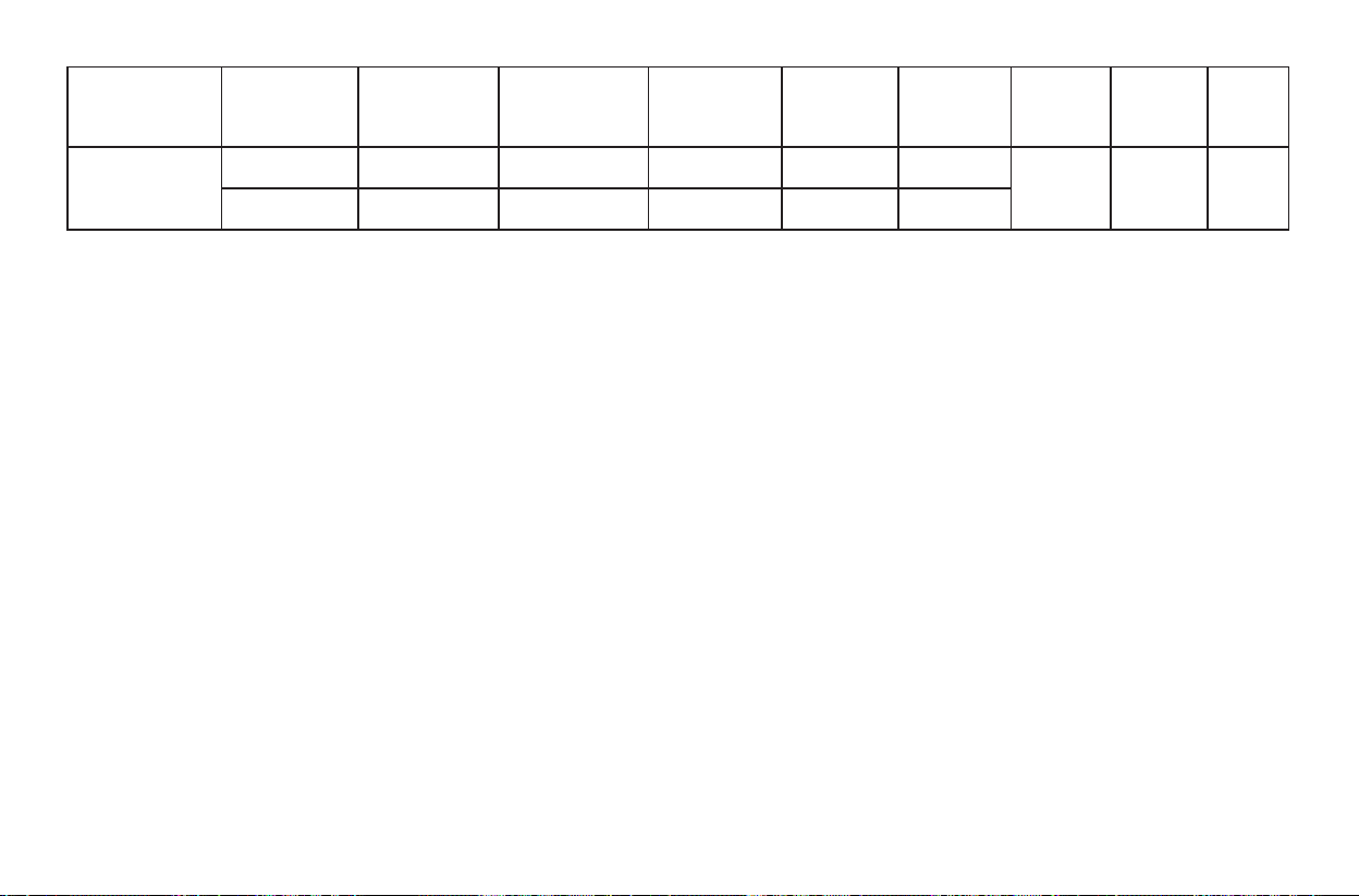
3. FUNCIONAMIENTO DEL TRANSMISOR:
A. Ponga la batería de 12 voltios (incluida). Para evitar que se dañe el
transmisor, retire la batería si no se utiliza durante un período
prolongado.
B. Guarde el transmisor lejos del exceso de calor o humedad.
C. Este mando a distancia está equipado con 16 combinaciones de
códigos para evitar posibles interferencias con otros mandos a
distancia, como abridores de puertas de garaje, alarmas de coche o
sistemas de seguridad. Si encuentra que el ventilador y kit de luces
se encienden y apagan sin usar su mando a distancia, simplemente
cambie el código de combinación en su transmisor y receptor.
D. Botones de funcionamiento en el panel del transmisor.
La función de las luces se controla pulsando la tecla. Mantenga
la tecla Mantenga pulsada la tecla para aumentar o disminuir la luz.
apagar o encender la luz Si se mantiene pulsado el
botón durante más de 0,7 segundos, se vuelve más tenue, la luz
varía cíclicamente en 0,8 segundos.
* El ventilador debe estar funcionando a cualquier velocidad antes
de pulsar el botón de "inversión"
E. Función de memoria:
Al apagar el ventilador o la luz con el mando de pared, se
memorizan y se recupera automáticamente a la última velocidad
del ventilador y/o la luz apagada
tecla para velocidad alta del ventilador.
tecla para velocidad media del ventilador.
tecla para velocidad baja del ventilador.
tecla para velocidad del ventilador o apagado.
tecla para encender las luces y mantenerla pulsada para atenuarlas
tecla para invertir el sentido de giro del ventilador (si el
ventilador tiene receptor de inversión)*
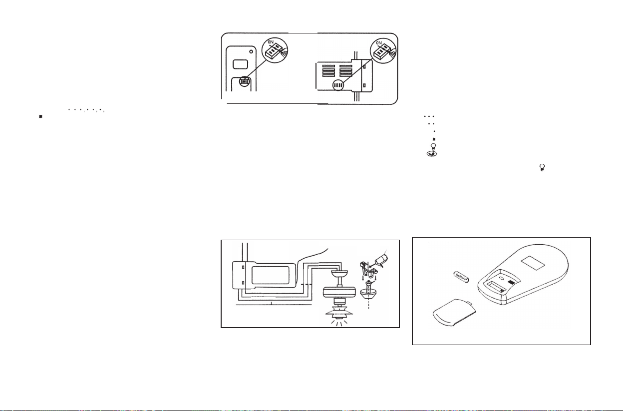
1. AJUSTE DEL CÓDIGO
Esta unidad tiene 16 combinaciones de códigos diferentes. Para ajustar
el código, siga estos pasos
A. Ajuste del código en el transmisor.
a. Retire la tapa de la batería. Presione firmemente debajo de la
flecha y deslice la tapa de la batería hacia afuera.
b. Deslice los interruptores de código a su elección de posición arriba
o abajo. El ajuste de fábrica es todo hacia arriba. No utilice esta
posición. Utilice un pequeño destornillador o un bolígrafo para
deslizar firmemente hacia arriba o hacia abajo (Imagen 16-1).
B. Ajuste del código en el receptor.
a. Deslice los interruptores de código a las mismas posiciones del
transmisor
b. Vuelva a colocar la tapa de la batería en el transmisor.
(Imagen 16-2).
2. INSTALACIÓN DEL RECEPTOR EN EL VENTILADOR DE TECHO
A. Precauciones de seguridad:
• ADVERTENCIA: ¡ALTA TENSIÓN!
• No utilice el control de velocidad del ventilador de estado sólido o
el control de pared del regulador de luz.
• El cableado eléctrico debe cumplir todos los requisitos de los
códigos eléctricos locales y nacionales.
• La fuente eléctrica y el ventilador deben tener un voltaje de
115/120 y 60Hz. Amperios máximos del motor del ventilador:
1,0.Vatios máximos de luz: 300W (incandescente)
• ¡La energía eléctrica doméstica puede causar lesiones graves o la
muerte!
Este mando a distancia está diseñado para controlar la velocidad del
ventilador de techo y el brillo de la luz por separado.
Hay cuatro botones para controlar la velocidad del ventilador y el
apagado.
Botón para controlar las luces
El botón de la luz encenderá las luces y las atenuará al máximoEl
indicador verde del transmisor se ilumina cuando se pulsa el botón.
INSTRUCCIONES DE INSTALACIÓN
Y FUNCIONAMIENTO
B. Instalación del receptor en el ventilador:
a. Desconecte la electricidad en el panel del disyuntor principal antes de
comenzar la instalación.
b. Retire el dosel del ventilador de techo del soporte de montaje
c. Desconecte el cableado existente entre el ventilador de techo y el suministro
en la caja de conexiones eléctricas.
d. Realice las conexiones como se indica a continuación, utilizando las tuercas
para cables suministradas:
Conecte el cable NEGRO de la unidad de control al cable NEGRO de
suministro (AC a Línea).
Conecte el cable BLANCO de la unidad de control al cable BLANCO de
suministro (AC a Neutro)
Conecte el cable BLANCO de la unidad de control (MOTOR N) al cable
BLANCO de alimentación.
Conecte el cable NEGRO de la unidad de control (MOTOR L) al cable
NEGRO del ventilador.
Conecte el cable azul de la unidad de control (para la luz) al cable azul de
la luz.
Si otros cables del ventilador o del suministro son de diferente color, haga
que esta unidad
sea instalada por un electricista cualificado.
e. Empuje todos los cables conectados hacia arriba en la caja de conexiones.
f. Coloque el cable negro de atea encima del receptor y ponga el receptor en el
soporte de montaje.
g. Vuelva a colocar la tapa en el soporte de montaje.
h. Restablezca la alimentación eléctrica.
ATENCIÓN:
No utilice el control de velocidad en el soporte de montaje que no se
describe en la imagen 17.
TRANSMISOR RECEPTOR
CÓDIGO
INTERRUP-
TORES
(IMAGEN 16-2)
INTERRUPTORES
DE CÓDIGO
(IMAGEN 16-1)
Imagen 17
SUMINISTRO
AC
RECEPTOR
PELADO
AZUL
BLANCO
NEGRO/ROJO
AZUL
BLANCO
NEGRO
NEGRO
BLANCO
VERDE

9. Cuidados del ventilador
Los ajustes de velocidad para clima cálido o frío
dependen de factores como el tamaño de la habitación,
la altura del techo, el número de ventiladores, etc.
NOTA: para usar la función inversa en este
ventilador, active el interruptor de inversión a la
posición opuesta. No accione el interruptor de
inversión mientras las aspas del ventilador estén
en movimiento. El ventilador debe estar apagado
y las aspas detenidas antes de invertir la dirección
de las aspas.
Tiempo cálido - (Hacia adelante) Un corriente de aire
hacia abajo crea un efecto de enfriamiento como se
muestra en la imagen 19. Esto le permite poner el aire
acondicionado en un ajuste más cálido sin afectar su
comodidad.
Tiempo frío - (Hacia atrás) Una corriente de aire
ascendente desplaza el aire caliente de la zona del techo
como se muestra en la imagen 20. Esto le permite poner
la unidad de calefacción en un ajuste más frío sin afectar
a su comodidad.
A continuación le ofrecemos algunas sugerencias para
ayudarle a mantener su ventilador.
1. Debido al movimiento natural del ventilador, algunas
conexiones pueden aflojarse. Revise las conexiones del
soporte, los soportes y las fijaciones de las aspas dos
veces al año. Asegúrese de que está todo bien firme.
(No es necesario retirar el ventilador del techo.)
2. Limpie su ventilador periódicamente para ayudar a
mantener un aspecto nuevo a lo largo de los años.
Utilice sólo un cepillo suave o un paño sin pelusas para
evitar rayar el acabado. El chapado está sellado con una
laca para minimizar la decoloración o el deslustre. No
utilice agua para limpiar el ventilador. Esto podría dañar
el motor, o la madera, o posiblemente causar una
descarga eléctrica.
3.Puede aplicar una ligera capa de cera para muebles a
las aspas de madera para obtener una protección
adicional y una mayor belleza. Cubra los pequeños
arañazos con una ligera aplicación de betún para
zapatos.
4.No es necesario engrasar el ventilador. El motor
tiene rodamientos permanentemente lubricados.
Imagen 19
Imagen 20
AVISO IMPORTANTE
ASEGÚRESE DE QUE LA ENERGÍA ESTÁ
DESCONECTADA EN LA CAJA DE
CONTROLES ELÉCTRICO ANTES DE
INTENTAR CUALQUIER REPARACIÓN.
CONSULTE LA SECCIÓN "CÓMO HACER
LAS CONEXIONES ELÉCTRICAS"
Interruptor
de reversa

Solución de problemas 10.
Solución
Mal funcionamiento
del mando a distancia
Problema
El ventilador no se enciende.
El ventilador hace ruido.
1.Revise los fusibles o los disyuntores del circuito.
2.Revise las conexiones de los cables del ventilador y las conexiones de los cables del interruptor en la carcasa del interruptor.
PRECAUCIÓN: Asegúrese de que la alimentación principal está desconectada.
1.Asegúrese de que todos los tornillos de la carcasa del motor estén bien ajustados.
2.Asegúrese de que los tornillos que unen el soporte de aspas del ventilador al cuerpo del motor están bien ajustadas.
3.Asegúrese de que las conexiones de tuerca de cable no choquen unas con otras o con la pared interior de la caja del interruptor.
PRECAUCIÓN: Asegúrese de que la alimentación principal está desconectada.
4.Póngalo o déjelo en funcionamiento durante 24 horas. La mayoría de los ruidos asociados a un nuevo ventilador desaparecen
durante este tiempo.
5.Si utiliza un kit de iluminación opcional, asegúrese de que los tornillos que aseguran la cristalería estén bien apretados.
Compruebe que la bombilla también está asegurada.
6.Asegúrese de que el florón superior esté a una corta distancia del techo. Pero no debe tocar el techo.
1. No conecte el ventilador con el control de velocidad variable montado en la(s) pared(es).
11.Especificaciones
7,20 kg 9,40 kg
1,41
52"
Estas son medidas aproximadas. No incluyen los amperios y vatios utilizados por el kit de iluminación.
©2022 Progress Lighting, Inc.
701 Millennium Blvd.,
Greenville, SC 29607
Todos los derechos reservados
135
288
672,90
1506,23
Baja
Alta
5,39
14,97
0,09
0,13
120
120
Tamaño del
ventilador
Velocidad Voltios Amperios Vatios RPM PCM P.N. P.B. M
3

