
Thank you for choosing Rough Country for all your suspension needs.
Rough Country recommends a certified technician install this system. In addition to these instructions, professional
knowledge of disassembly/reassembly procedures as well as post installation checks must be known. Attempts to
install this system without this knowledge and expertise may jeopardize the integrity and/or operating safety of the
vehicle.
Please read instructions before beginning installation. Check the kit hardware against the parts list on
the next page. Be sure you have all needed parts and know where they go. Also, please review tools needed list
and make sure you have the needed tools.
PRODUCT USE INFORMATION
As a general rule, the taller a vehicle is, the easier it will roll. Seat belts and shoulder harnesses
should be worn at all times. Avoid situations where a side rollover may occur.
Generally, braking performance and capability are decreased when larger/heavier tires and wheels are used. Take
this into consideration while driving. Do not add, alter, or fabricate any factory or after-market parts to increase vehi-
cle height over the intended height of the Rough Country product purchased. Mixing component brands is not recom-
mended.
Rough Country makes no claims regarding lifting devices and excludes any and all implied claims. We will not be
responsible for any product that is altered. If questions exist we will be happy to answer any questions concerning
the design, function, and correct use of our products.
This vehicle will require the EPAS (Electronic Power Assist Steering) plugs to be disconnect-
ed prior to beginning installation of this kit. See installation instructions. Failure to disconnect these plugs
may result in damage to the EPAS module resulting in an error message being displayed, which will require
replacement of the EPAS module.
DEALER AND VEHICLE OWNER
Any vehicle equipped with any Rough Country product should have a “Warning to Driver” decal in-
stalled on the inside of the windshield or on the vehicle’s dash. The decal should act as a constant reminder for
whoever is operating the vehicle of its unique handling characteristics.
INSTALLING DEALER - it is your responsibility to install the warning decal and forward these installation instructions
on to the vehicle owner for review. These instructions should be kept in the vehicle for its service life.
Note to installer : Before installation begins we recommend that a test drive be performed. While driv-
ing check for uncommon sounds and/or vibrations . What you feel and hear during the test drive will only magnify
once lift kit is installed. Advise you to discuss possible issues identified from drive with customer before proceeding
to install this kit.
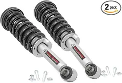
2004-18 Ford F150 Loaded Strut Instructions
Ford F-150 Loaded Strut
Tools Needed
5mm Allen
8mm Wrench/Socket
10mm Wrench/Socket
15mm Wrench/Socket
18mm Wrench/Socket
21mm Wrench/Socket
27mm Wrench/Socket
30mm Wrench/Socket
Hand Vacuum Pump
Torque Wrench
Hammer
Floor Jack
Jack Stands
Torque Specs:
Size Grade 5 Grade 8
5/16” 15 ft/lbs 20 ft/lbs
3/8” 30 ft/lbs 35 ft/lbs
7/16” 45 ft/lbs 60 ft/lbs
1/2” 65 ft/lbs 90 ft/lbs
9/16” 95 ft/lbs 130 ft/lbs
5/8” 135 ft/lbs 175 ft/lbs
3/4” 185 ft/lbs 280 ft/lbs
Class 8.8 Class 10.9
12MM 55ft/lbs 75ft/lbs
14MM 85ft/lbs 120ft/lbs
16MM 130ft/lbs 165ft/lbs
18MM 170ft/lbs 240ft/lbs
1. Jack up the front of the vehicle and support the vehicle with jack stands, so that the front wheels are off the
ground. Next, remove the front tires/wheels, using a 21mm deep well socket.
2. Using a 15mm socket remove the front skid, if the truck is equipped with a full front skid.
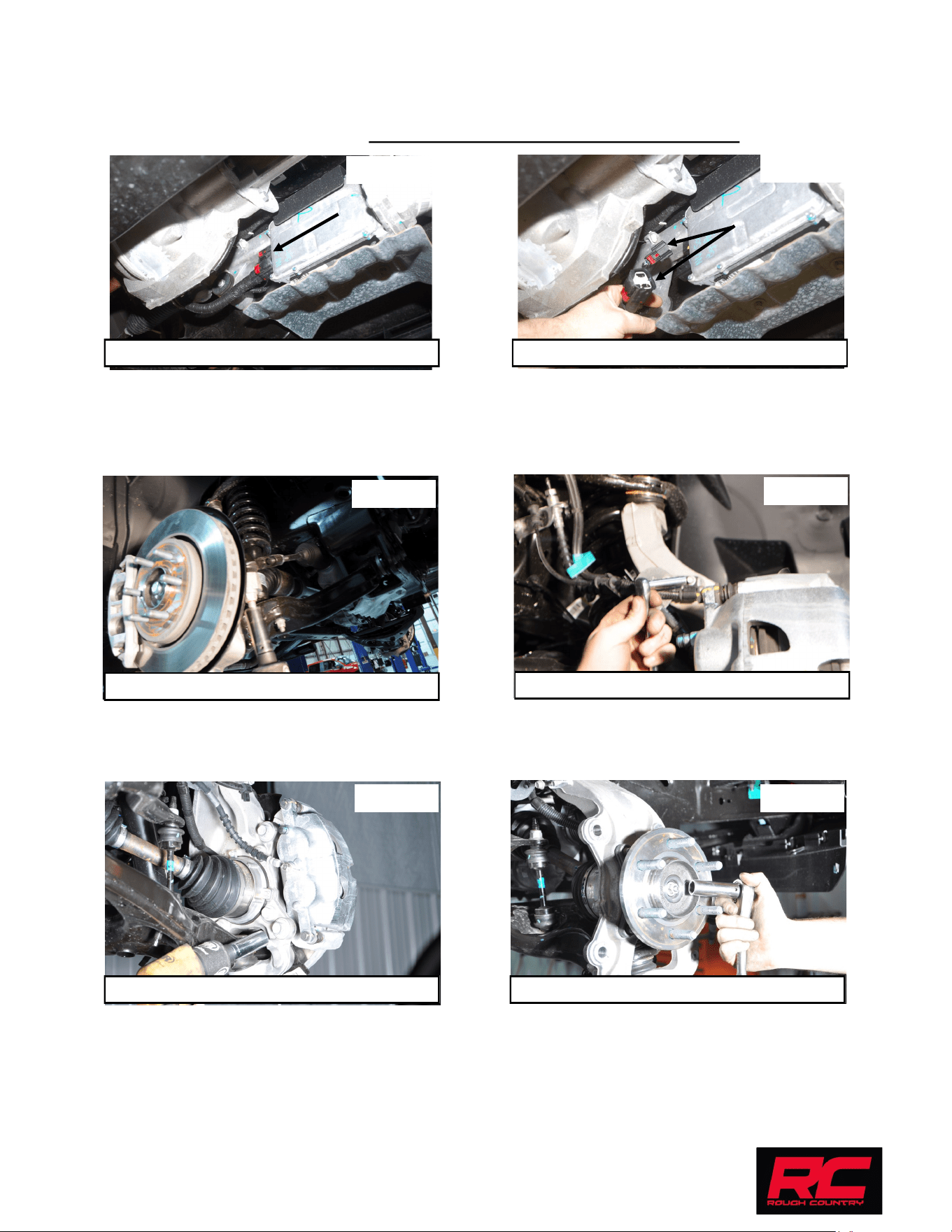
3. Disconnect the EPAS (Electronic Power Assist Steering) Plugs as shown located on the steering assembly by
the front differential. See Photo 1 & 2. This must be done BEFORE installation is started.
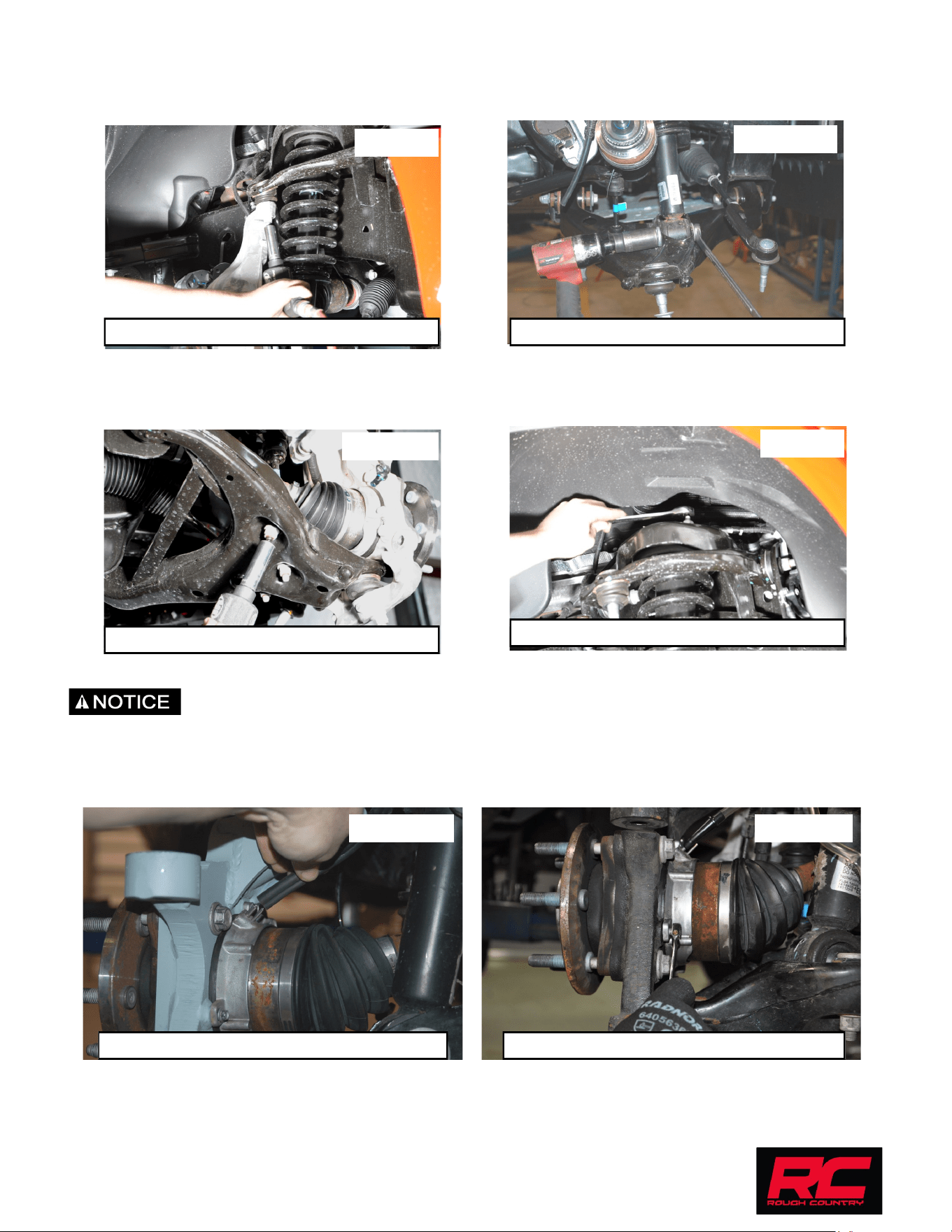
4. Using a 21mm wrench remove the nut from the tie rod on the knuckle. Using a tie rod/ball joint puller, remove the
tie rod from the knuckle. Push linkage forward to make room for installation. Retain factory hardware. See Photo
3.
5. Using a 8mm socket remove the ABS bracket from the knuckle and also remove the brake line bracket with a
10mm socket. See Photo 4.
6. Next remove the caliper bolts with a 18mm socket as shown in Photo 5 and the dust shield bolts with a 8mm
socket. Remove the ABS wire from the knuckle with a 5mm Allen wrench.
7. Use a pair of pliers to pull off the axle dust cap and remove the axle nut with a 15mm socket. See Photo 6.
8. Remove the sway bar nut using a 18mm wrench. Retain factory hardware.
9. Using a 21mm wrench and a 1 1/16” socket loosen the lower control arm bolts. Do not remove the bolts just
loosen them so you can later swing the lower control arm down.
INSTALLATION INSTRUCTIONS
Photo 3
Photo 4
Photo 5 Photo 6
Photo 1
Photo 2
Locate the EPAS plug. Unplug the EPAS.
Remove the tie rod end from the knuckle.
Remove the ABS bracket from the knuckle.
Remove the brake caliper. Remove the axle nut.
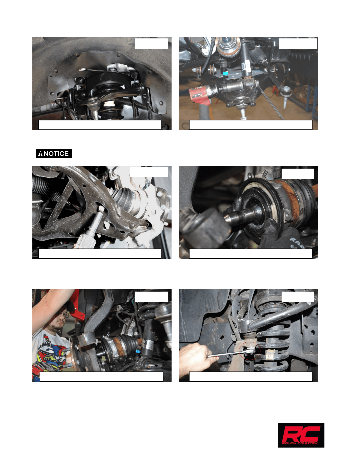
10. Place jack stand under the knuckle for support. Remove upper control arm nut, using a 18mm wrench. Using the
appropriate tool remove the ball joint to separate from the upper control arm. Do not allow the knuckle to pull out
far enough that it pulls the shaft out of the differential. See Photo 7.
11. Remove the lower strut bolt using a 30mm socket and 27mm wrench for 04-13 models and 18mm socket for 14-
18 models. See Photos 8a&b. Retain hardware for reuse.
12. Using a 18mm wrench, remove the nuts on the upper strut tower that holds the assembly in place. See Photo 9.
13. Lower the jack to let the lower control arm and knuckle swing down so the strut can be removed.
14. Remove the upper control arm.
We recommend using OE instructions for disassembly and assembly of IWE actuator, the
following instructions are for reference only.
15. Disconnect vacuum tubes from the actuator. See Photo 10.
16. Using a 8mm wrench, remove the (3) bolts securing the actuator to the knuckle. See Photo 11.
17. Push CV axle inward allowing the knuckle to pivot outward to allow for more clearance to remove the strut.
Photo 7
Photo 8a
Photo 9
Photo 10 Photo 11
Remove the upper control arm nut. Remove the lower strut bolt. 04-13 Models
Remove the upper strut nuts.
Remove the vacuum tubes from the actuator. Remove the actuator bolts from the knuckle.
Photo 8b
Remove the lower strut bolts. 14-18 Models
18. Install the supplied strut in the upper mount using the factory hardware. Tighten using an 18mm wrench. See
Photo 12.
19. Install the lower strut bolt using a 30mm socket and 27mm wrench for 04-13 models and 18mm socket for 14-18
models. See Photos 13a&b. Retain hardware for reuse.
20. We recommend using OE instructions for disassembly and assembly of IWE actuator, the following in-
structions are for reference only.
21. Make sure the actuator splines line up to the splines on the CV shaft. See photo 14.
22. Install CV shaft into the knuckle assembly. See Photo 15.
23. Using a floor jack, raise the lower control arm and connect the upper ball joint on the upper control arm to the
spindle. Tighten using an 18mm wrench. See Photo 16.
Photo 14
Photo 15
Align actuator splines on CV shaft.
Install CV shaft into knuckle.
Photo 16
Install upper ball joint in knuckle.
Photo 12 Photo 13a
Install the upper strut hardware. Install the lower strut bolt. 04-13 Models
Photo 13b
Install the lower strut bolts. 14-18 Models
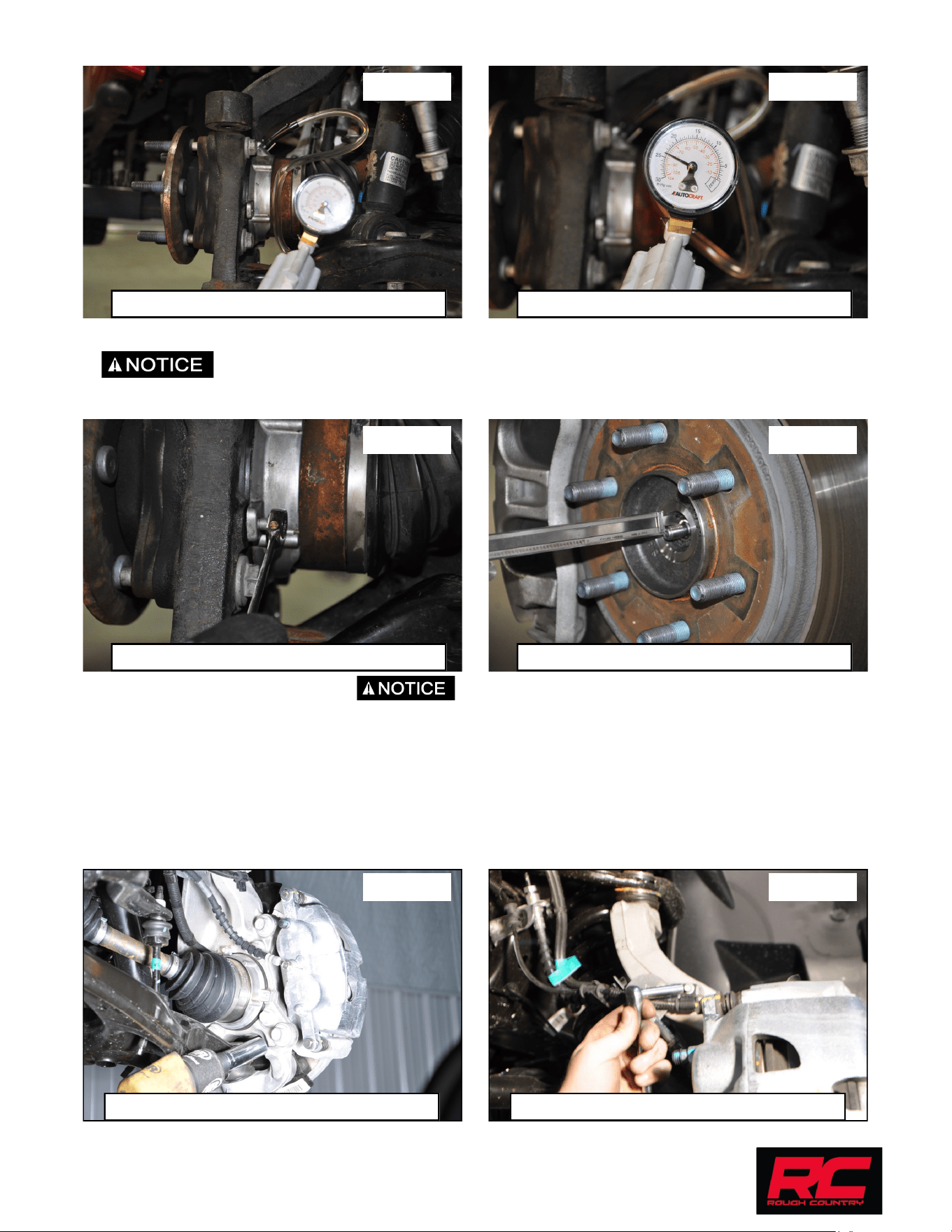
24. Reinstall the steering linkage nut using a 21mm wrench. Using a hand vacuum pump, apply and hold 24inHG of
vacuum to the actuator through the large port. See Photos 17 and 18.
25. Install the (3) bolts securing the actuator to the knuckle and tighten using an 8mm wrench. See Photo 24.
26. With vacuum still applied to actuator. Measure the depth of the CV shaft threads protruding
through the hub bearing. If minimum 15.5mm or .61” is not achieved, rotate the hub to eliminate binding of the
splines. See Photo 25.
27. Install axle nut and tighten to 30 lb.ft. Do Not Use an impact, caution must be taken or damage to
shaft may occur.
28. Verify free rotation of the hub with NO CV shaft rotation. No clicking or grinding noise should be present
29. Release the vacuum from the actuator and rotate the hub to engage the actuator. You may hear/feel the actua-
tor engage.
30. Verify that the hub and CV rotate together. Reconnect the vacuum lines to the actuator.
31. Next slide on the brake rotor and install the brake caliper with the factory hardware. Torque to factory specs us-
ing an 18mm socket. See Photo 21.
32. Install the ABS line and brake line onto the knuckle using the factory hardware. Torque to factory specs using an
8mm socket and a 10mm socket. See Photo 22.
Photo 17 Photo 18
Photo 19 Photo 20
Use vacuum to hold the actuator in. 24inHG of vacuum.
Install the actuator bolts. Check CV depth in knuckle.
Install the ABS bracket on the knuckle. Install the brake caliper.
Photo 21 Photo 22
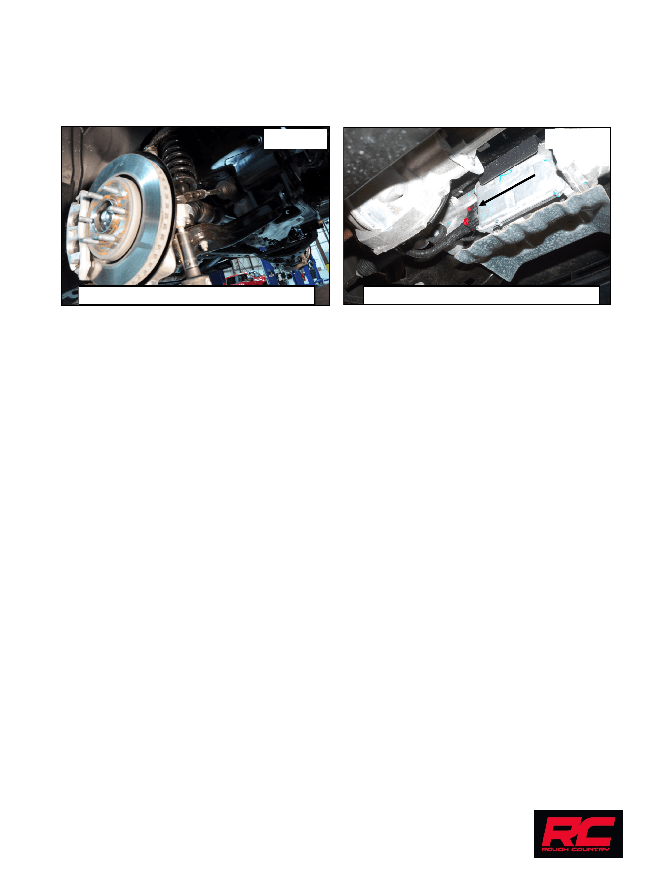
33. Install the tie rod end on the knuckle using the factory hardware. Tighten using a 21mm wrench. See Photo 23.
34. Repeat steps 4-33 on opposite side of vehicle.
35. Using a 18mm wrench, reinstall sway bar using factory hardware. Torque to factory specs.
36. Install the wheels / tires, using a 21mm deep well socket.
37. Reconnect the EPAS plugs. See photo 24.
38. Jack up the vehicle and remove the jack stands. Lower the vehicle to the floor and torque all bolts to factory
specifications.
39. Vehicle will have to have a front-end alignment.
By purchasing any item sold by Rough Country, LLC, the buyer expressly warrants that he/she is in compliance with
all applicable , State, and Local laws and regulations regarding the purchase, ownership, and use of the item. It shall
be the buyers responsibility to comply with all Federal, State and Local laws governing the sales of
any items listed, illustrated or sold. The buyer expressly agrees to indemnify and hold harmless
Rough Country, LLC for all claims resulting directly or indirectly from the purchase, ownership, or
use of the items.
Reconnect the EPAS plug. Install the tie rod end in the knuckle.
Photo 23 Photo 24
Thank you for choosing Rough Country for all your suspension needs.