Version 1
December 29, 2025
For Models ECB601 and ECB501 only
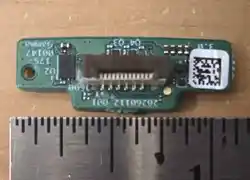
Model: EB-POS24G FCC ID: WR926POSMRSAN1 IC: 7981A-26POSMRSAN1
Confidential
2
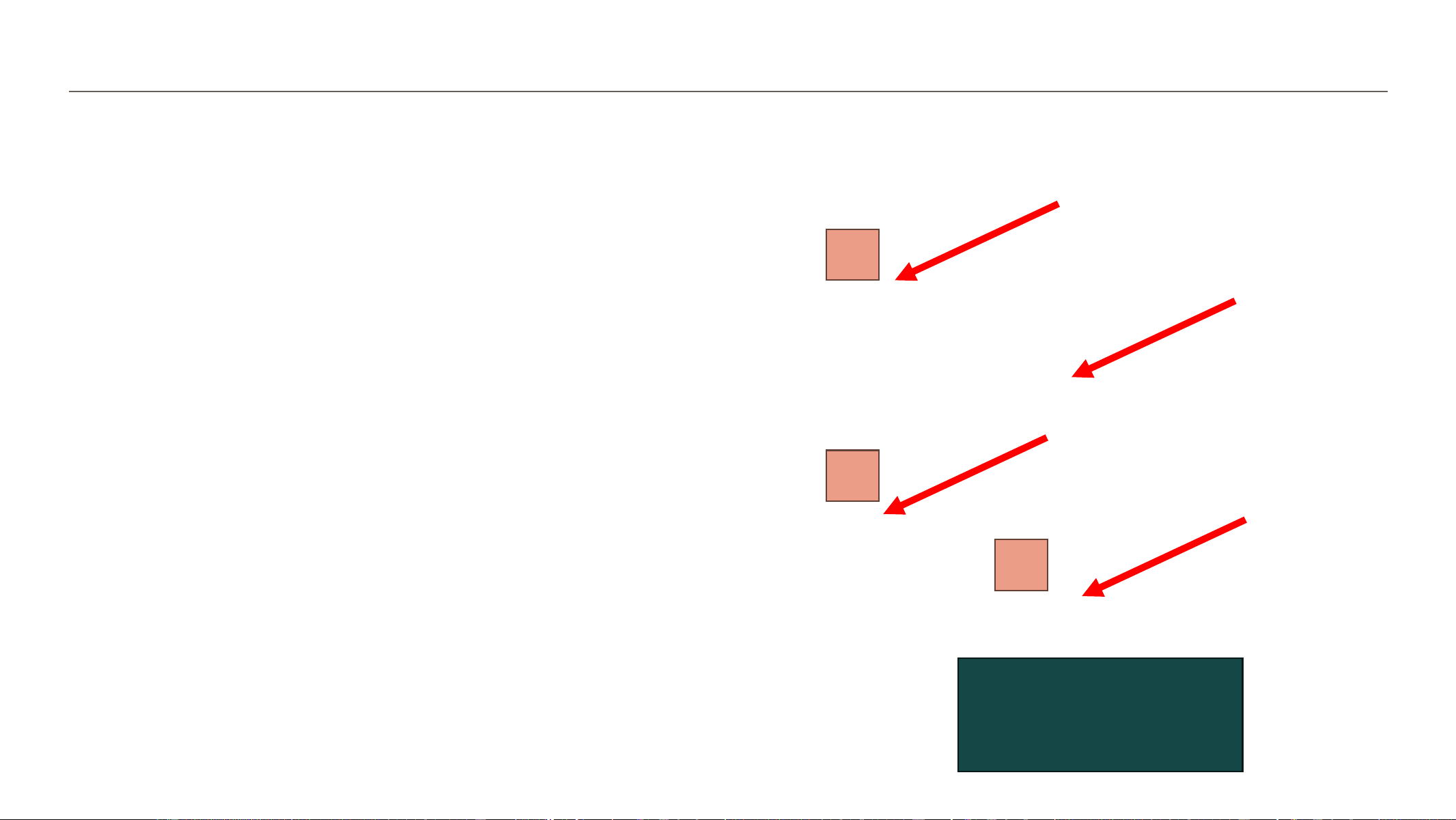
Disassembly - Remove Rear Housing
1
2
3
1. Remove the 4 screws holding the backing plate in place
2. Remove rear cover
3. Using a plastic wedge, lift the rear housing away from the
front housing
Screw Torque
6.0 +/- 0.2 kgf-cm

Confidential
3
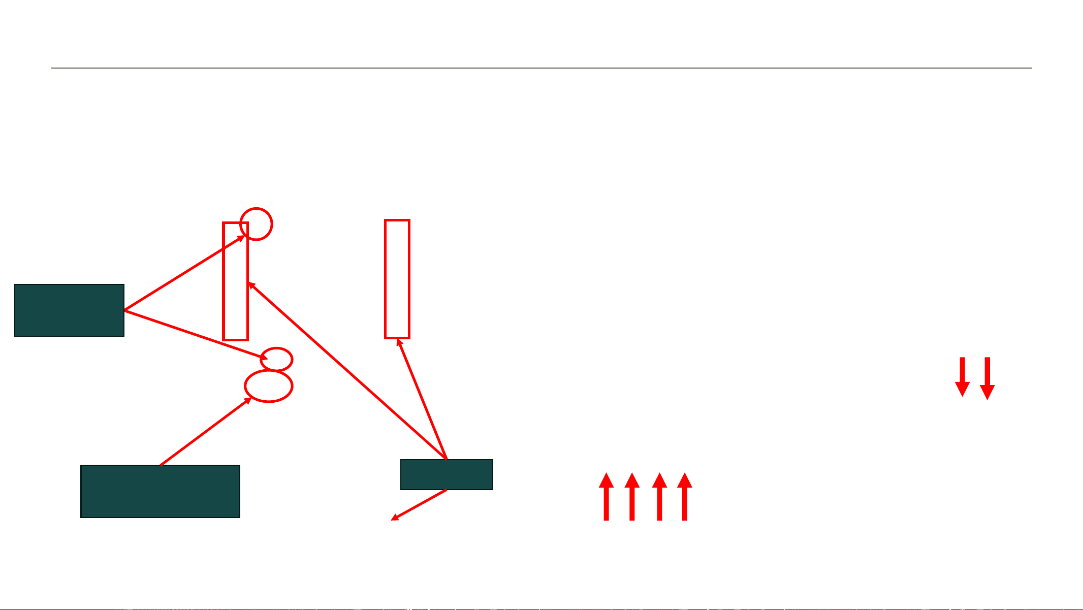
6. Remove and set aside the two gaskets
7. Detach the speaker wire connector by gently
tugging up.
8. Open FFC flex connector drawer
9. Gently tug the FFC flex connector up to detach
Disassembly – Gaskets and Connectors
FFC Flex
Connector
Wire
connectors
Gaskets
Confidential
4
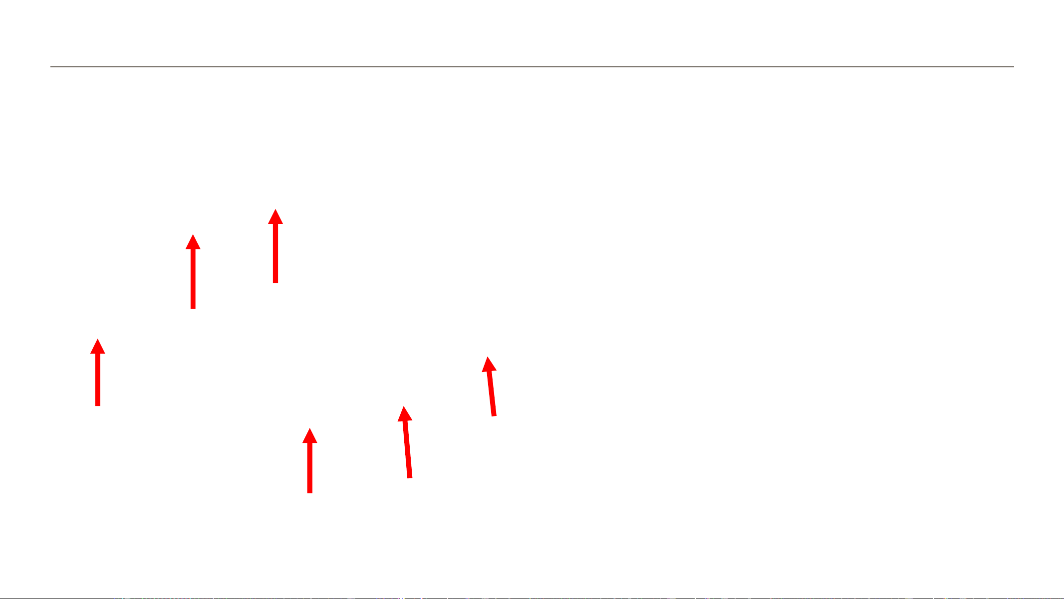
Front Housing to Rear Housing Disassembly
1. Pull apart both sub assembly halves. Ensure FPC Cable
and speaker connector are lose during disassembly.

Confidential
5
Disassembly – Front Housing Radar Board PCBA Connections
1. Open FFC flex connector
2. Remove FFC flex cable from
PCBA connector
FFC Flex
Connector

Confidential
6
Front Housing – Radar Board Insertion and removal
1. Ensure orientation of radar board is correct
2. Insert radar board into the LDS frame
3. Reverse the process to remove the radar board

Confidential
7
Front Housing – PCBA Connections
1. Insert Radar flex into PCBA
connector, check the silk screen line
is parallel with connector.
2. Insert Radar FFC flex into connector.
3. Close connector.
Confidential
8
6. Insert the two gaskets
7. Connect the speaker wire connector by lining up
the connector and gently pushing down.
8. Open FFC flex connector drawer
9. Gently push the FFC flex connector in and close
the drawer to latch flex in
Assembly – Gaskets and Connectors
FFC Flex
Connector
Wire
connectors
Gaskets
Confidential
9
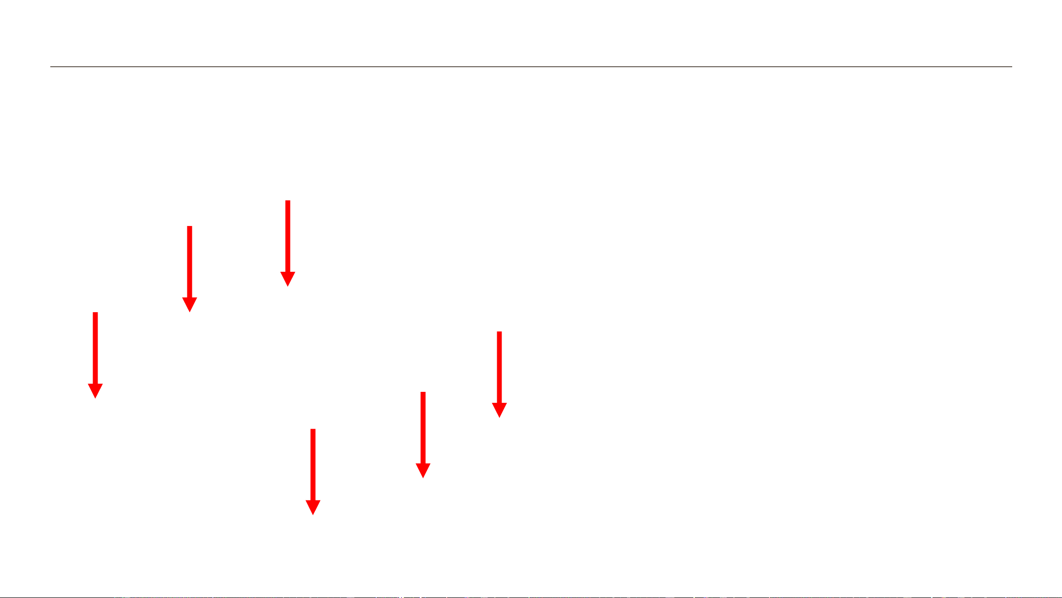
Front Housing to Rear Housing Assembly
1. Bring both sub assembly halves together as a clamshell.
Ensure FPC Cable does not get caught underneath
during assembly.
Confidential
10
Full Unit Assembly – Rear Cover
1. Place rear cover into opening of housing.
2. Insert and torque 4x screws.
3. Torque screws in the following pattern as labelled below.
Torque
6.0 +/- 0.2 kgf-cm
4
3
1
2
Photos for reference purposes only
1
2
3
4

Confidential
11
Regulatory Approvals
This Limited Modular Approved device complies with FCC 15.249 & 15.209 rules and RSS-210 requirements. The host device manufacturer is responsible for compliance to any
other FCC/ISED rules that apply to the host not covered by the modular transmitter grant certification. The final host device will require Part 15 Subpart B/ICES-003
compliance testing with the modular transmitter installed.
This module is not sold separately and is not intended/installed to be used in any host except for Ecobee Inc. Models ECB601 and ECB501 and in case where the module will be
integrated in other non-identical hosts in the future, we will expand the LMA to include the new hosts after an appropriate assessment to the FCC/ISED rules.
Integration instructions for host device manufacturers can be found below and are compliant with the KDB 996369 D03 OEM Manual v01.
Specific Operational Use Conditions
The module is tested for mobile RF exposure use conditions. Using the module for portable conditions will require additional assessment though a Class II permissive change or
a change in FCC ID through a new application.
The host manufacturer installing this module into their product must ensure that the final product complies with the FCC and/or ISED requirements by a technical assessment
or evaluation against the FCC and/or ISED rules. The host manufacturer must be aware not to provide information to the end user regarding how to install or remove this RF
module in the user’s manual of the end product which integrates this module. The host’s end-user manual shall include all required regulatory information/warning as
shown in this manual.
The module are not permitted to be used in satellites and aircrafts.
Limited Module Procedure
This limited module approved transmitter does not have a RF shield over the transmitter portion of the device and the transmitter is not tested in stand-alone configuration
The end host shall ensure spurious radiated emissions meets FCC and ISED rules.
Integration instructions

Confidential
12
RF Exposure Conditions
A 20 cm minimum distance must be maintained between the antenna and the users for the host device this module is integrated into. Under such
configuration, the FCC radiation exposure limits set forth for an uncontrolled environment can be satisfied. Further RF exposure shall be re-
evaluated to the scenario of portable and co-located use.
Antenna
Antenna is integrated in the RF chip. Tx antenna gain is 3 dBi. No external antenna connection is required for normal function of the radar.
User Manual of the End Product
In the user manual of the end product, the end user must be informed to keep at least 20 cm separation with the antenna while this end product is installed and operated. The
end user must be informed that the FCC radio-frequency exposure guidelines for an uncontrolled environment can be satisfied.
The end user must also be informed that any changes or modifications not expressly approved by the manufacturer could void the user’s authority to operate this equipment.
Label and compliance information
The final end product must be labeled, in a font size of 4pt or greater, in a visible area with the following:
Contains FCC ID: WR926POSMRSAN1
Contains IC: 7981A-26POSMRSAN1
Integration instructions Continued

Confidential
13
Additional Notice
This module is intended for internal use with the specific platform ECB601 and ECB501. The integrator is responsible for the compliance to all the rules that apply to the
product into which this certified limited RF module is integrated. Additional testing and certification may be necessary when multiple transmitter are used.
A Class II permissive change is required if the module is integrated in different hosts.
1. Radiated field strength must be tested per ANSI C63.10-2020 and comply with FCC Part 15.249, RSS-210 Annex B.10 requirements. After the module is installed into
the host device, the fundamental Emission must not exceed the field strength document in the test report (88 dBµV/m, AVG). The field strength shall be measured
using an Average detector with RBW = 1 MHz and Peak detector with RBW = 1 MHz. The DUT have one channel – radiated power measurement should be
performed with frequency range greater than 24000 – 24250 MHz.
2. Transmitter Spurious Emissions must be tested per ANSI C63.10-2020 and comply with FCC Part 15.249(d), 15.209, RSS-210 Annex B.10(b), and RSS-Gen Section 8.9.
The field strength for frequencies above 1 GHz shall be measured using an Average and Peak detector with RBW = 1 MHz; frequencies at or below 1 GHz shall be
measured using a Quasi-Peak detector with RBW = 120 kHz. The frequency range to be investigated is from 9 kHz up to the 5
th
harmonic or 100 GHz.
3. If connected to public AC Mains network, an assessment of conducted emissions should be performed as per FCC Part 15.207 and RSS-GEN Section 8.8. AC power
line conducted emissions shall be measured using a Quasi-Peak and Average detector with RBW = 9 kHz from 150 kHz to 30 MHz.
4. RF Exposure should be re-examined if the use case has been changed to ensure the RF exposure compliance from the initial filling is still applicable If no longer
applicable, KDB 447498 D04 and other appropriate FCC RF Exposure procedure should be consulted and consideration of C2PC procedure if required per FCC policy.
A 20 cm minimum distance has to be able to be maintained between the antenna and the users for the host this module is integrated into. Under such configuration, the
radiation exposure limits set forth for a population/ uncontrolled environment can be satisfied. Further RF exposure shall be re-evaluated to the scenario of portable, and
collocated use.
Integration instructions Continued