PDF export of the original HTML instructions
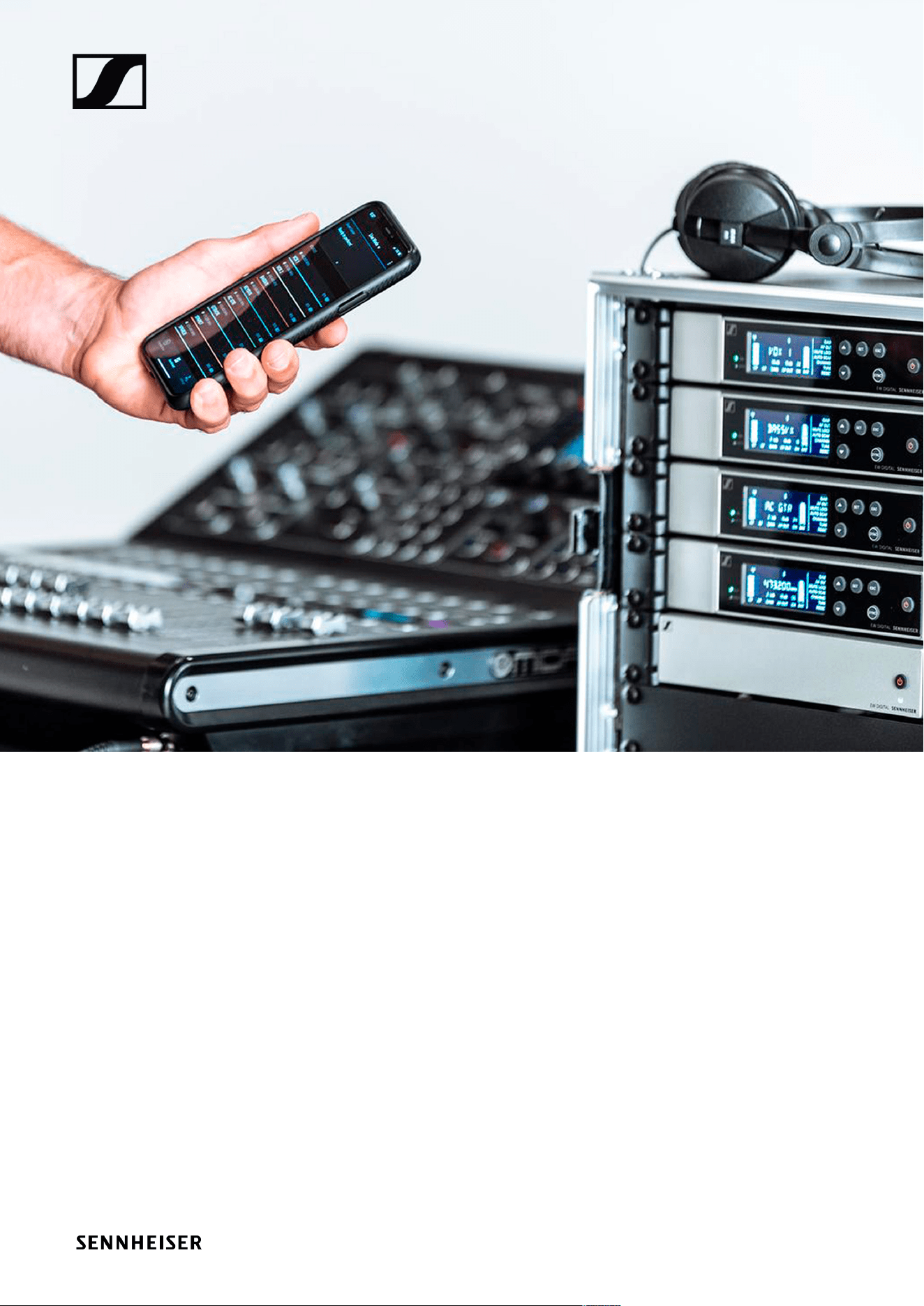
Evolution Wireless Digital
Evolution Wireless Digital v5.7 | 11/2025

Contents
1. Preface...........................................................................................................................................10
2. Product information..................................................................................................................... 11
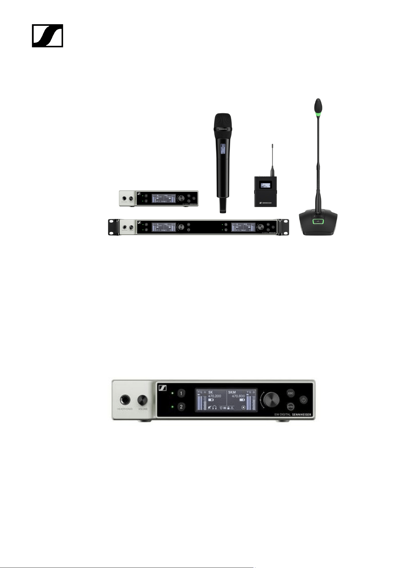
Products of the EW-D series.................................................................................................. 11
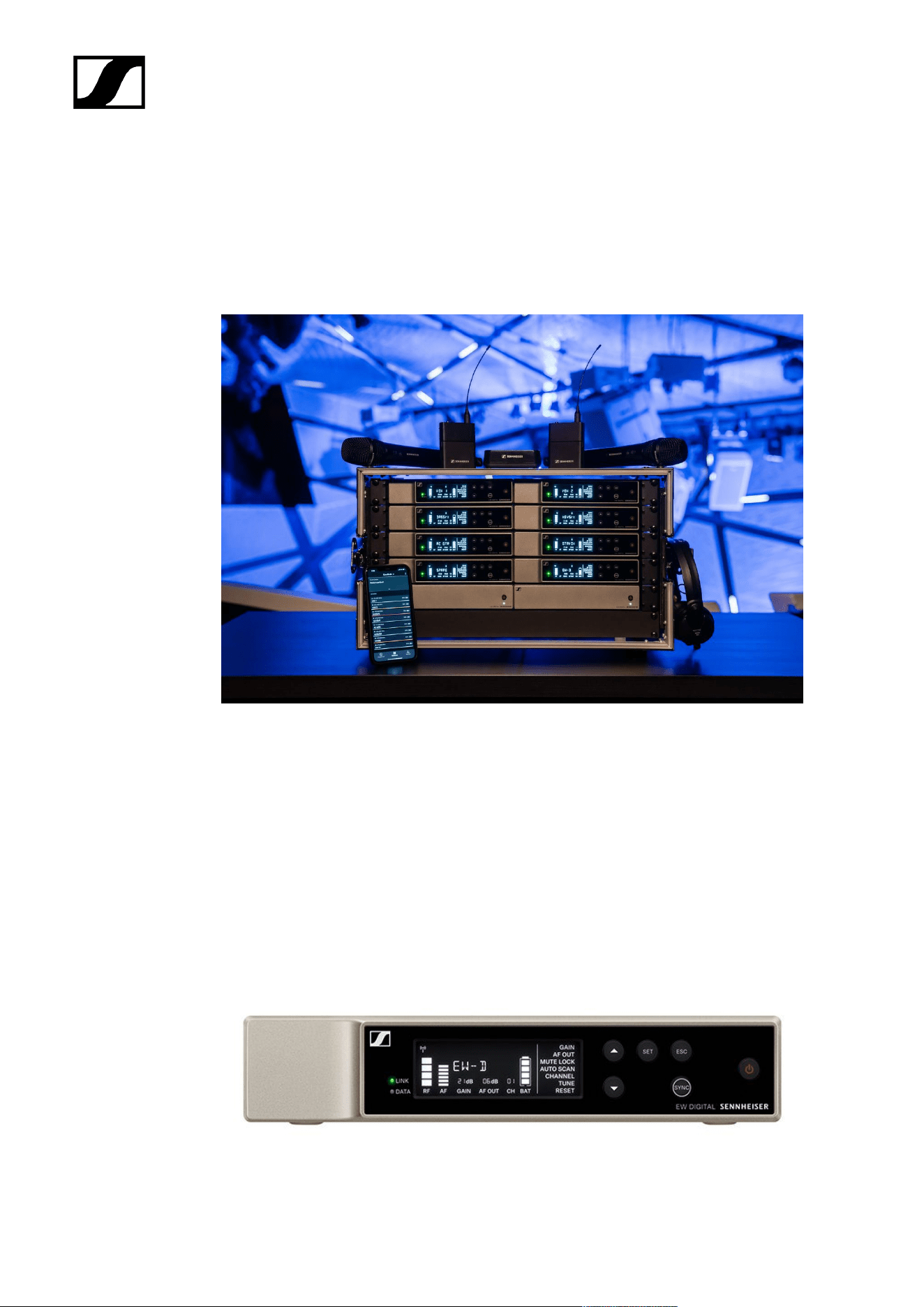
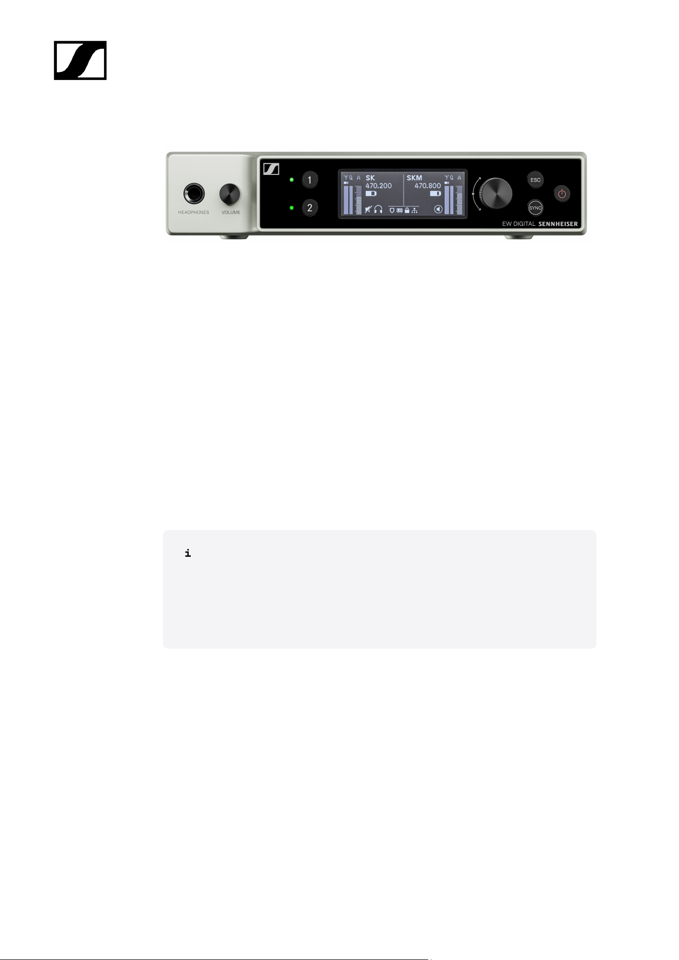
EW-D EM rack receiver....................................................................................................11
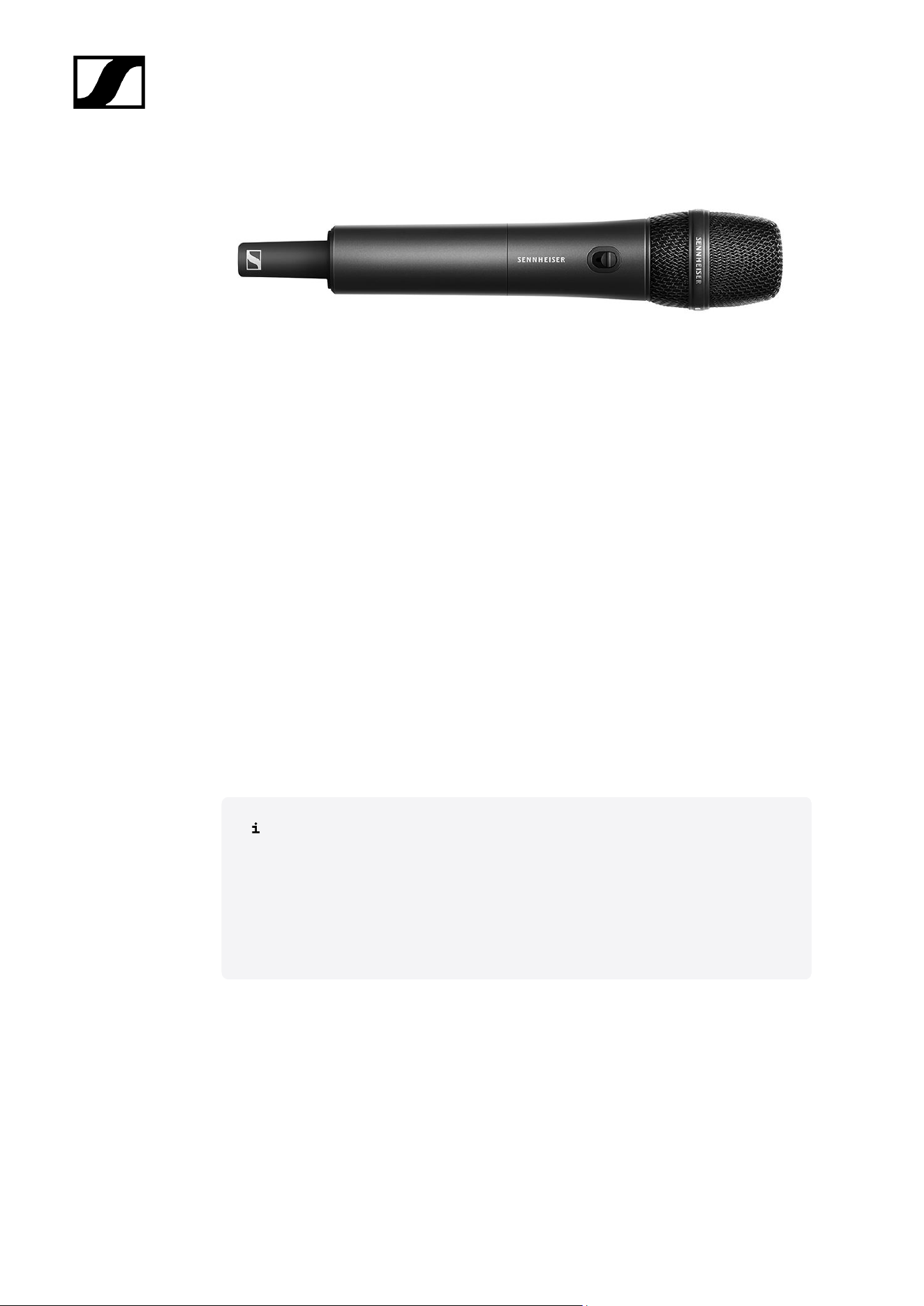
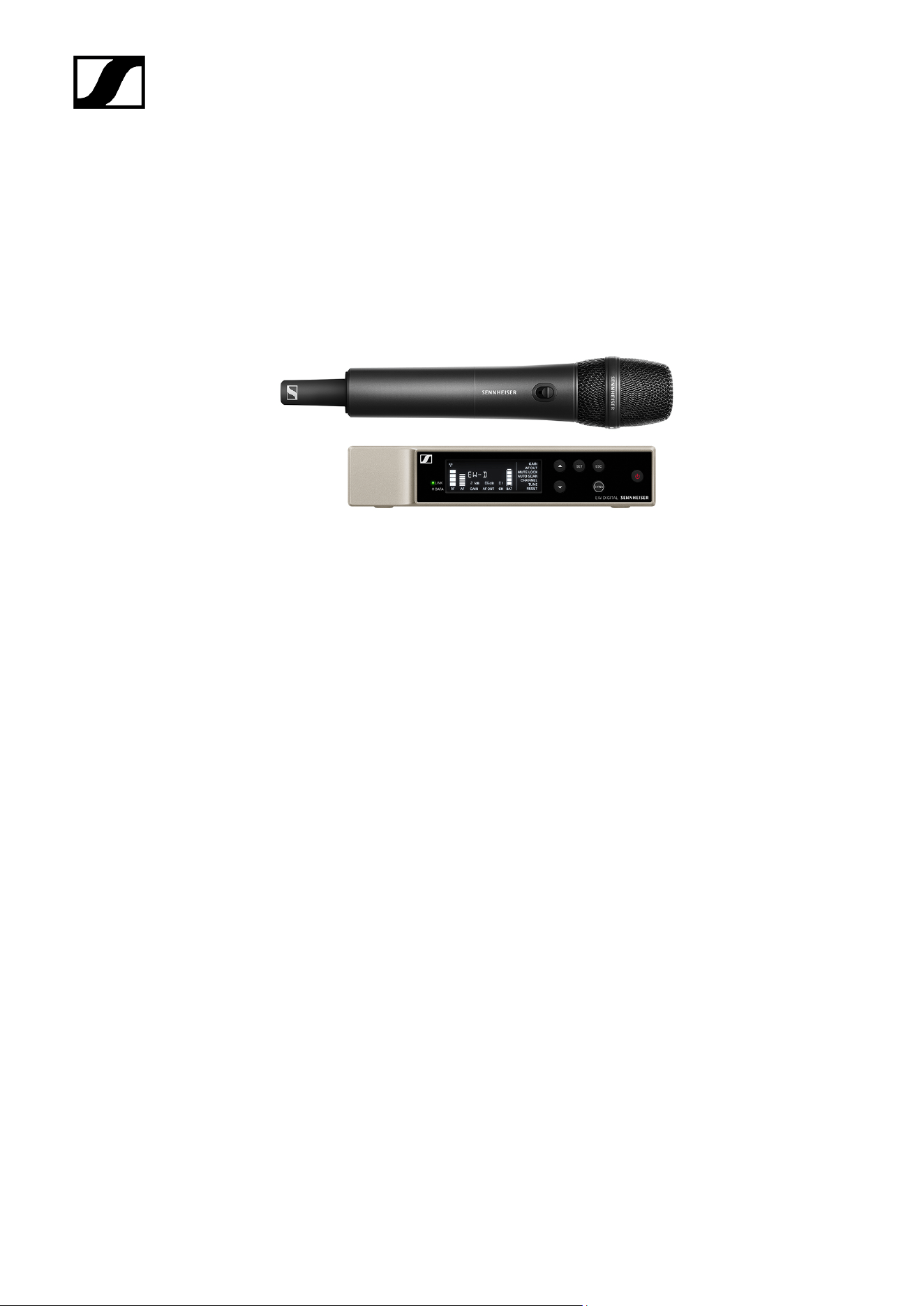
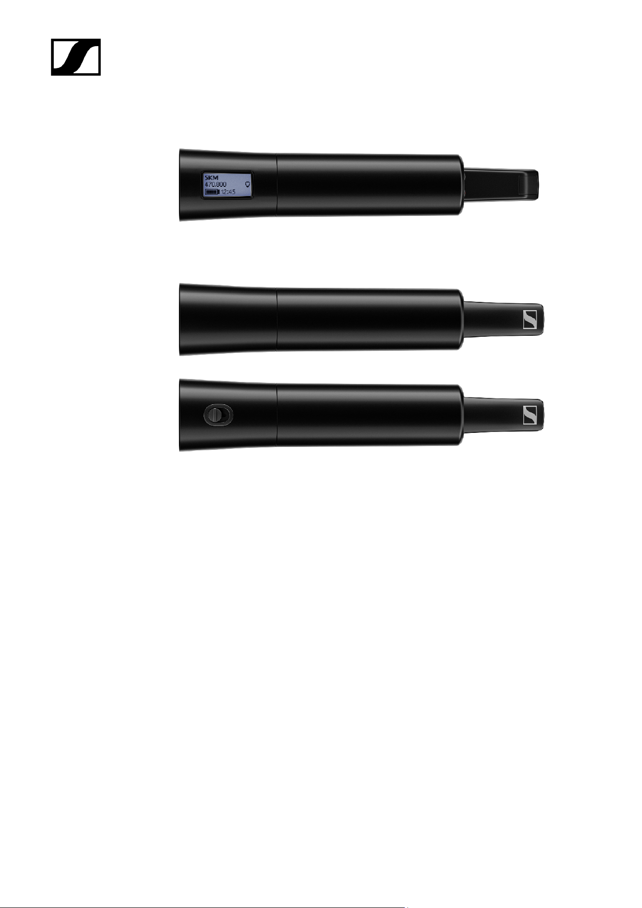
EW-D SKM-S handheld transmitter............................................................................... 13
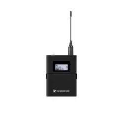
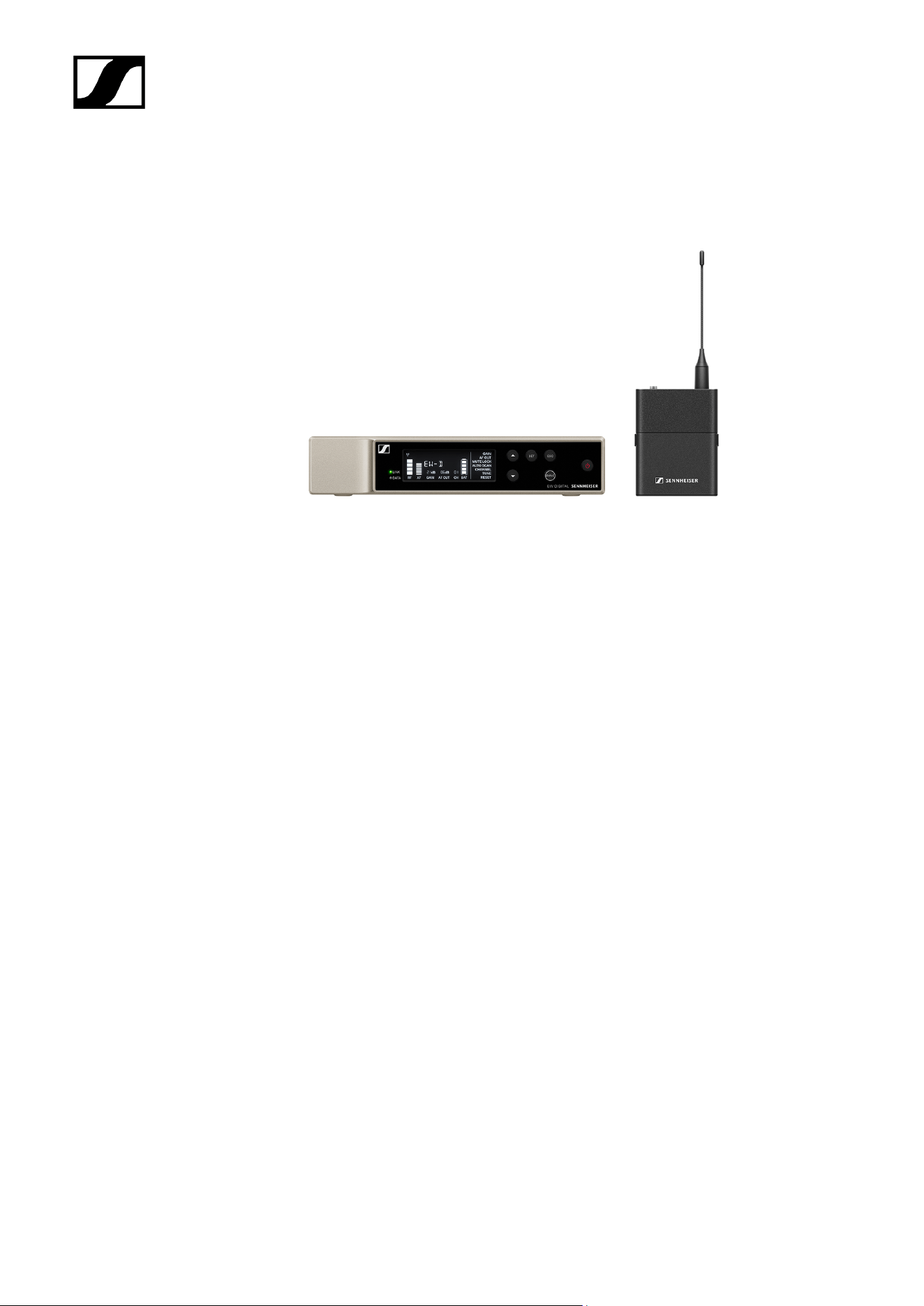
EW-D SK bodypack transmitter..................................................................................... 14
Sets available for the EW-D series........................................................................................16
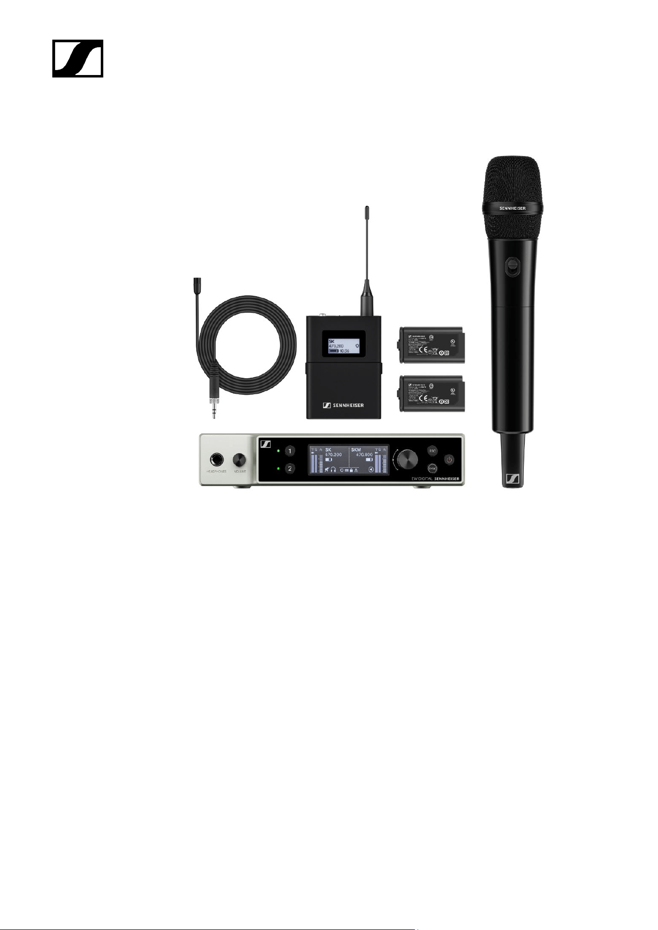
EW-D ME2 SET | Lavalier Set.........................................................................................16
EW-D ME3 SET | Headmic Set.......................................................................................18
EW-D ME4 SET | Lavalier Set........................................................................................20
EW-D Cl1 SET | Instrument Set......................................................................................22
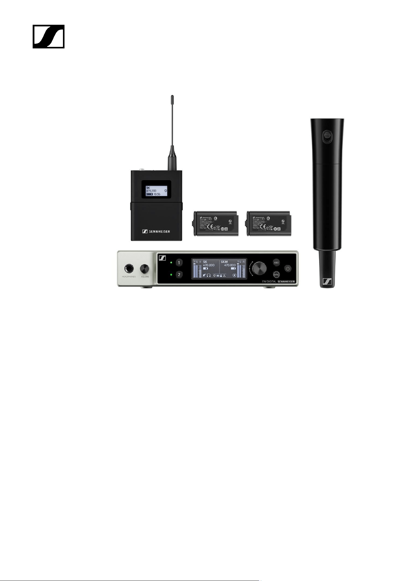
EW-D SK BASE SET | Base Set..................................................................................... 24
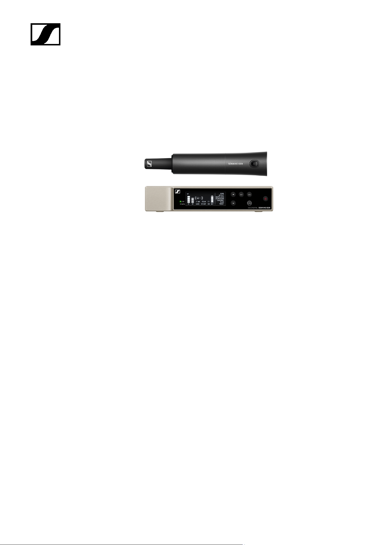
EW-D 835-S SET | Handheld Set.................................................................................. 26
EW-D SKM-S BASE SET | Base Set.............................................................................. 28
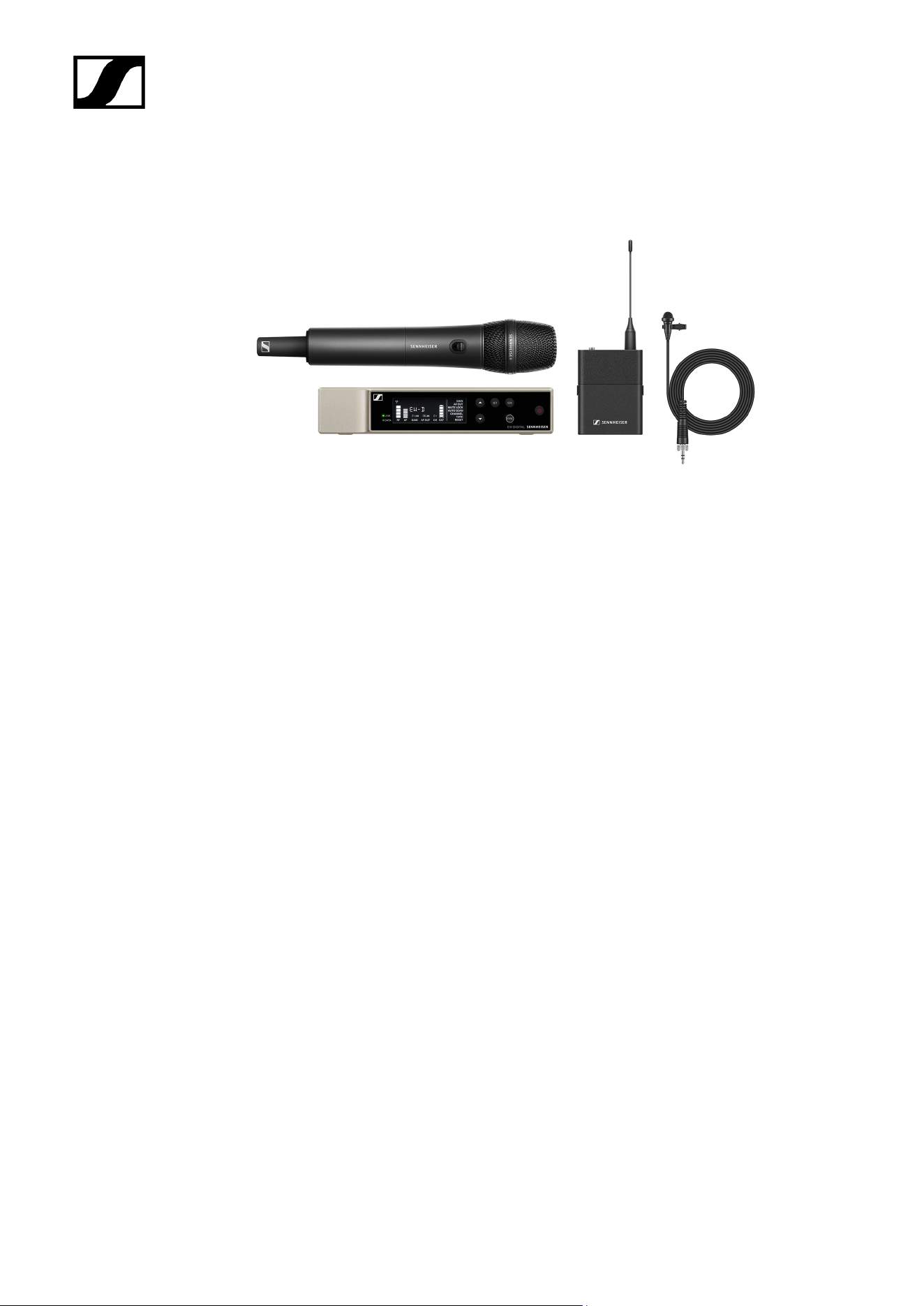
EW-D ME2/835-S SET | Combo Set.............................................................................30
Products of the EW-DX series...............................................................................................32
EW-DX EM 2 rack receiver............................................................................................. 32
EW-DX EM 2 Dante rack receiver................................................................................. 34
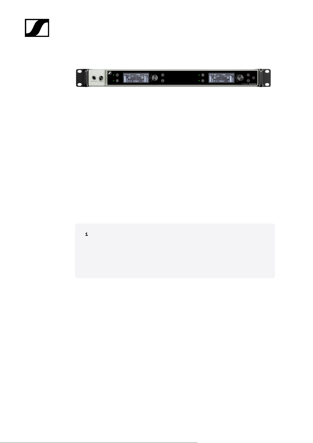
EW-DX EM 4 Dante rack receiver................................................................................. 35
EW-DX SKM | EW-DX SKM-S handheld transmitter...................................................36
EW-DX SK | EW-DX SK 3-PIN bodypack transmitter..................................................38
Table stand EW-DX TS 3-pin | EW-DX TS 5-pin..........................................................40
Sets available for the EW-DX series.....................................................................................42
EW-DX 835-S SET | Handheld Set................................................................................ 42
EW-DX MKE 2 SET | Lavalier Set.................................................................................. 44
EW-DX MKE 2-835-S SET | Combo Set........................................................................46
EW-DX SK-SKM-S BASE SET | Base Set......................................................................48
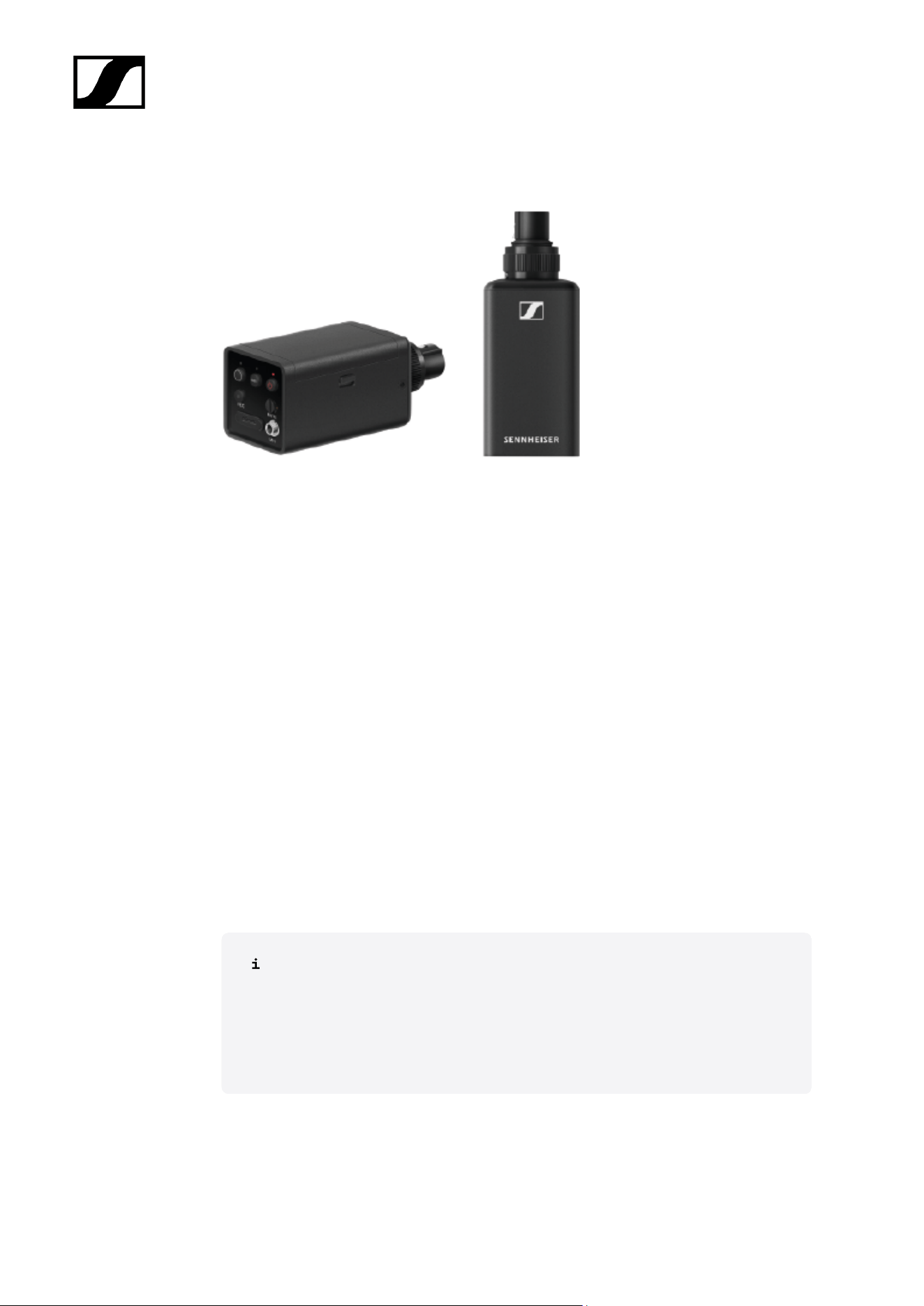
Products of the EW-DP series...............................................................................................50
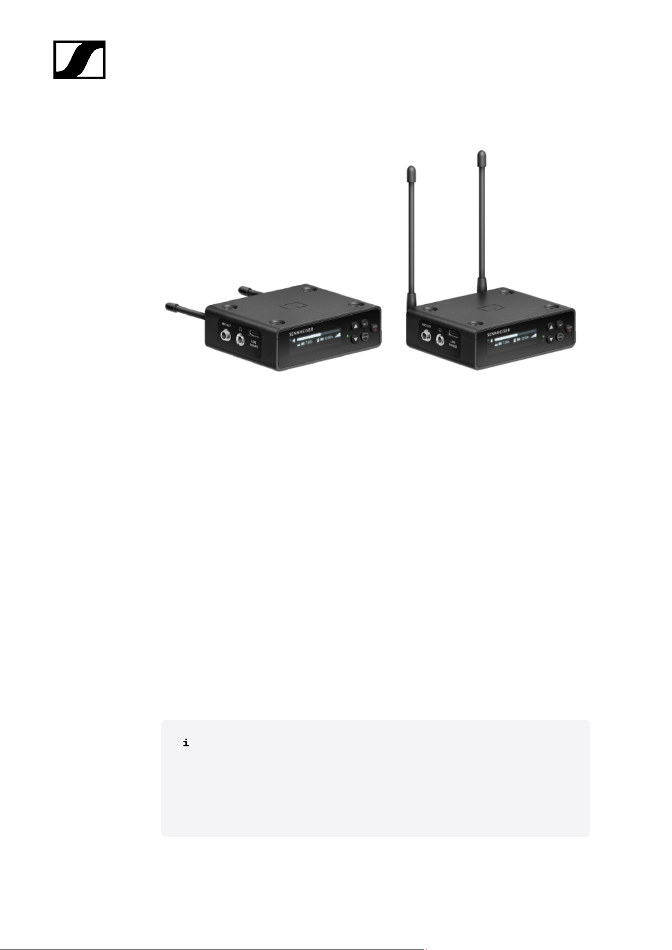
EW-DP EK portable receiver...........................................................................................51
EW-DP SKP plug-on transmitter....................................................................................52
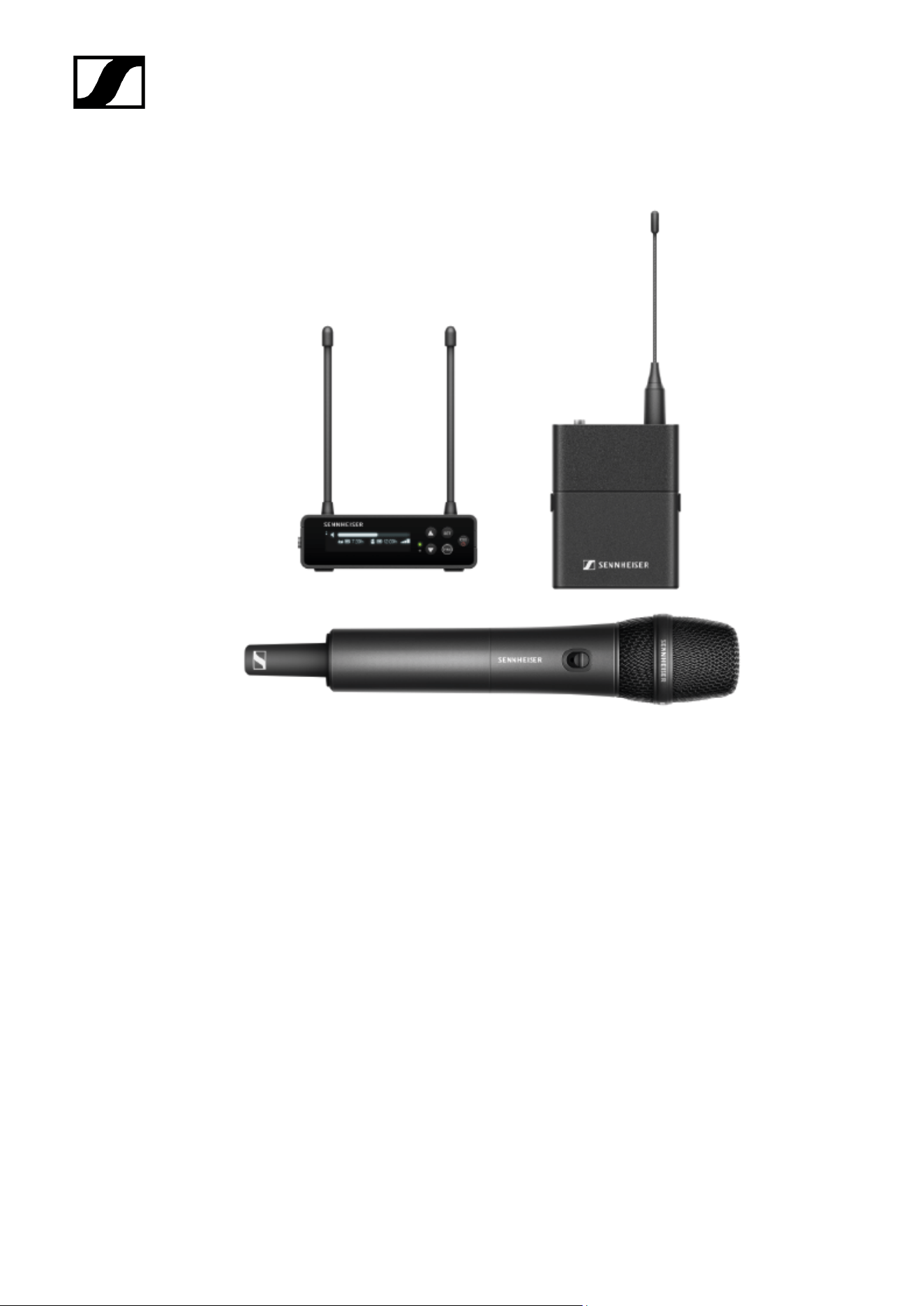
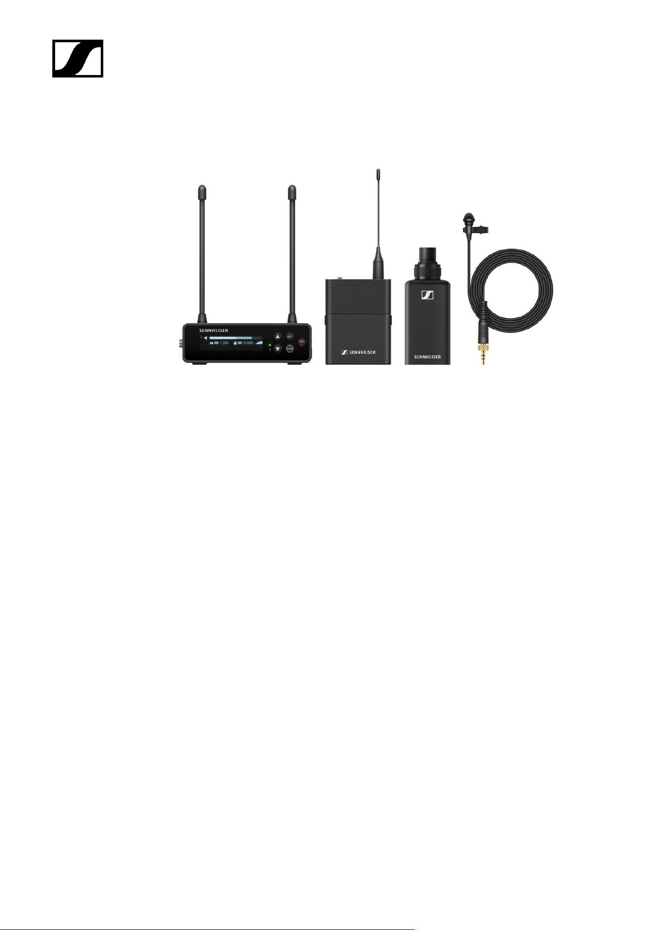
Sets available for the EW-DP series.....................................................................................53
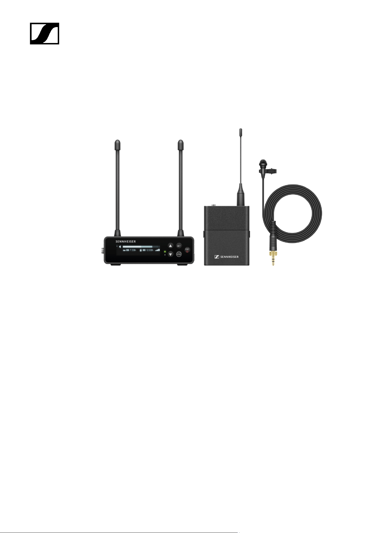
EW-DP ME-2 | Lavalier Set.............................................................................................53
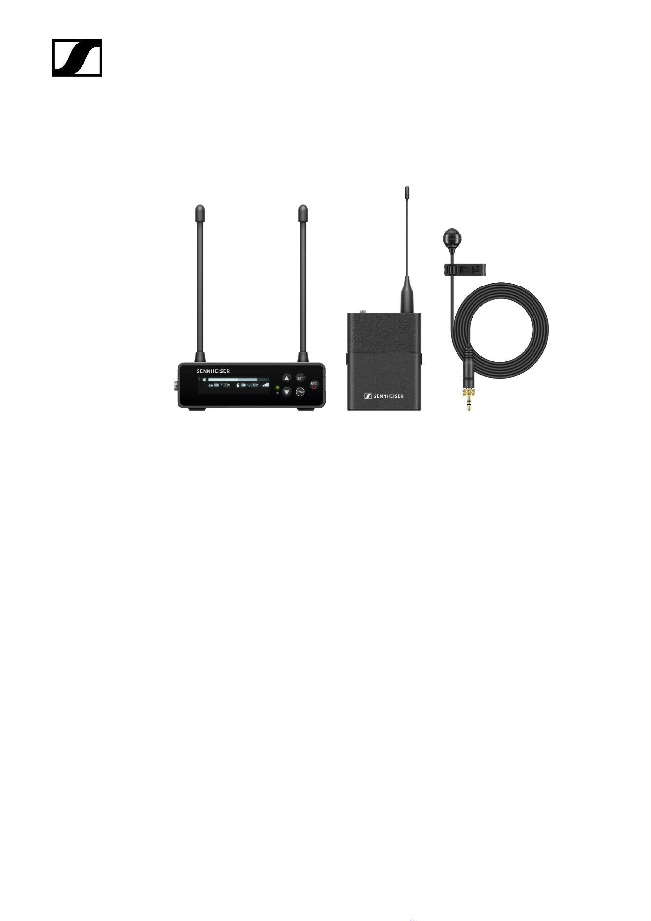
EW-DP ME-4 | Lavalier Set............................................................................................ 55
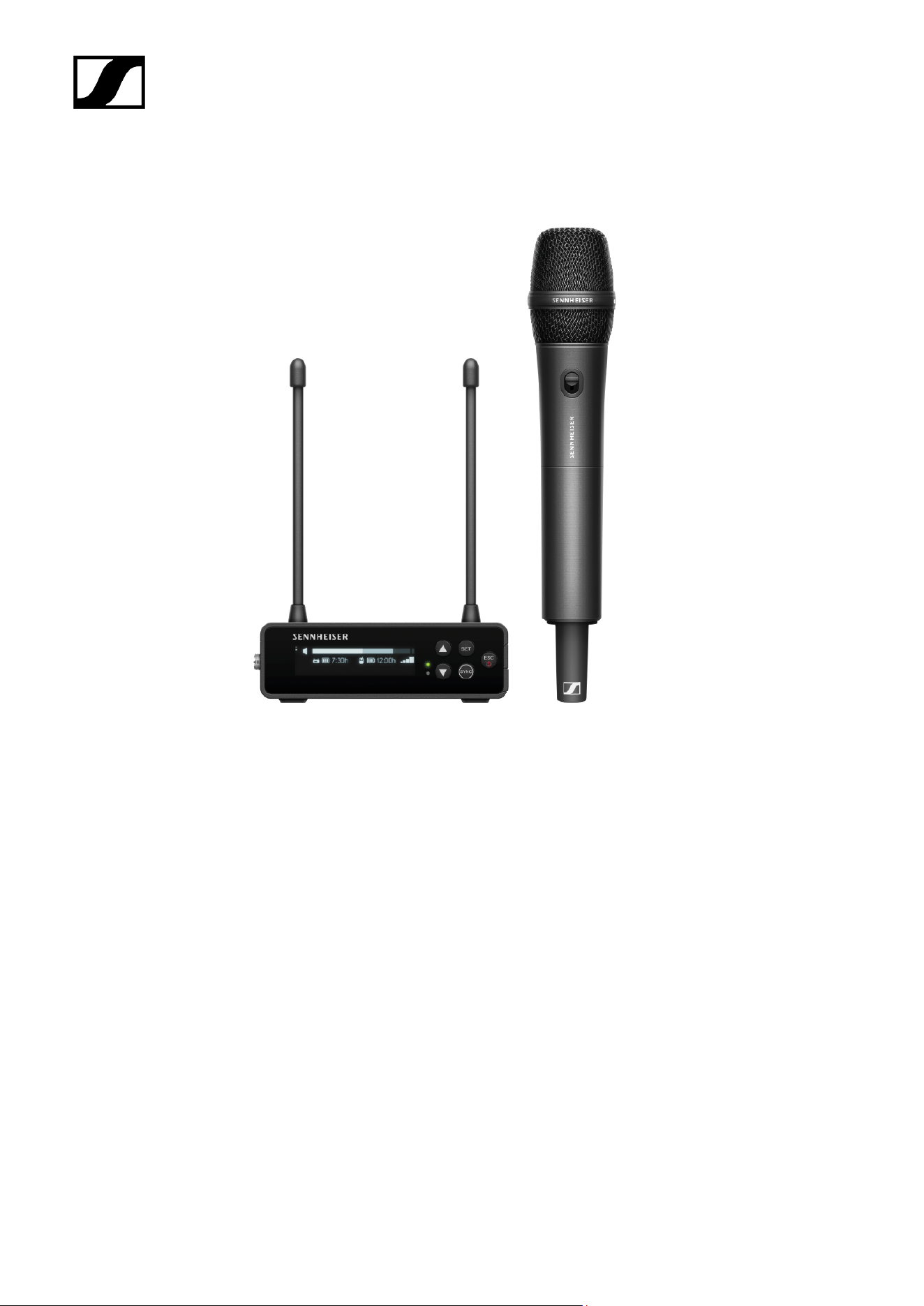
EW-DP 835 | Handheld Set............................................................................................ 57
EW-DP ENG | Lavalier Set..............................................................................................59

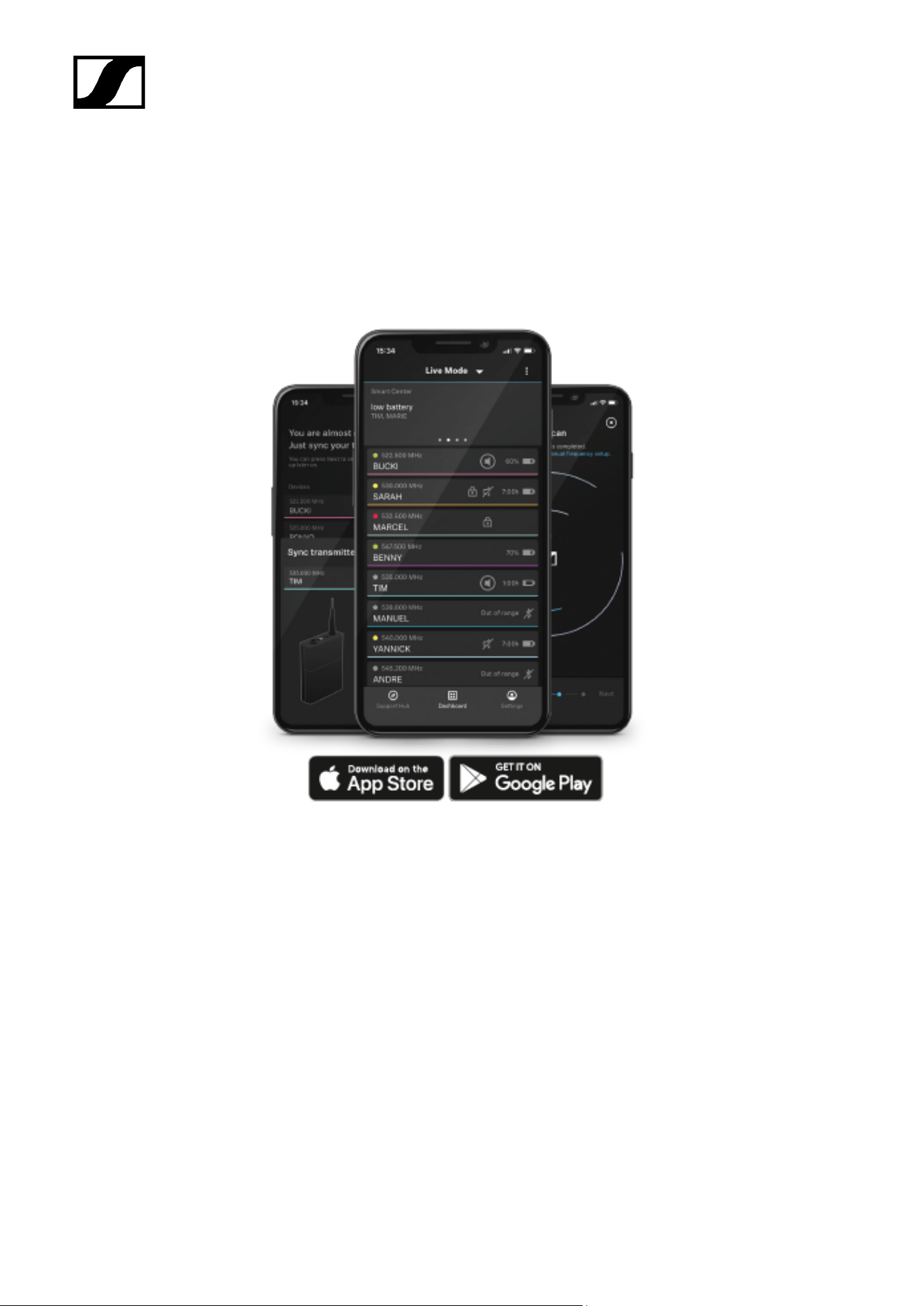
Smart Assist app......................................................................................................................61
Accessories...............................................................................................................................62
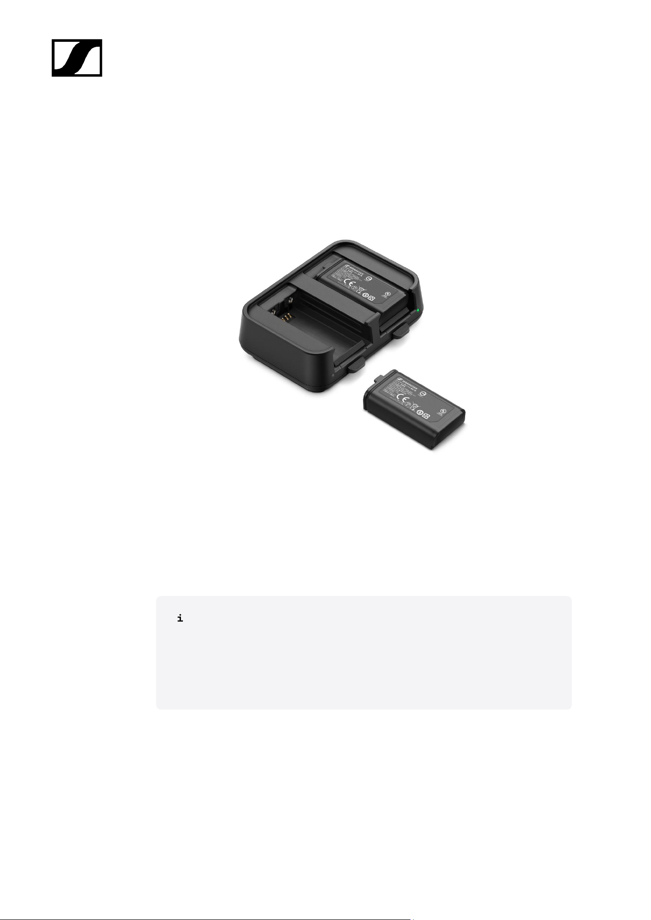
BA 70 rechargeable battery and L 70 USB charger.................................................... 62
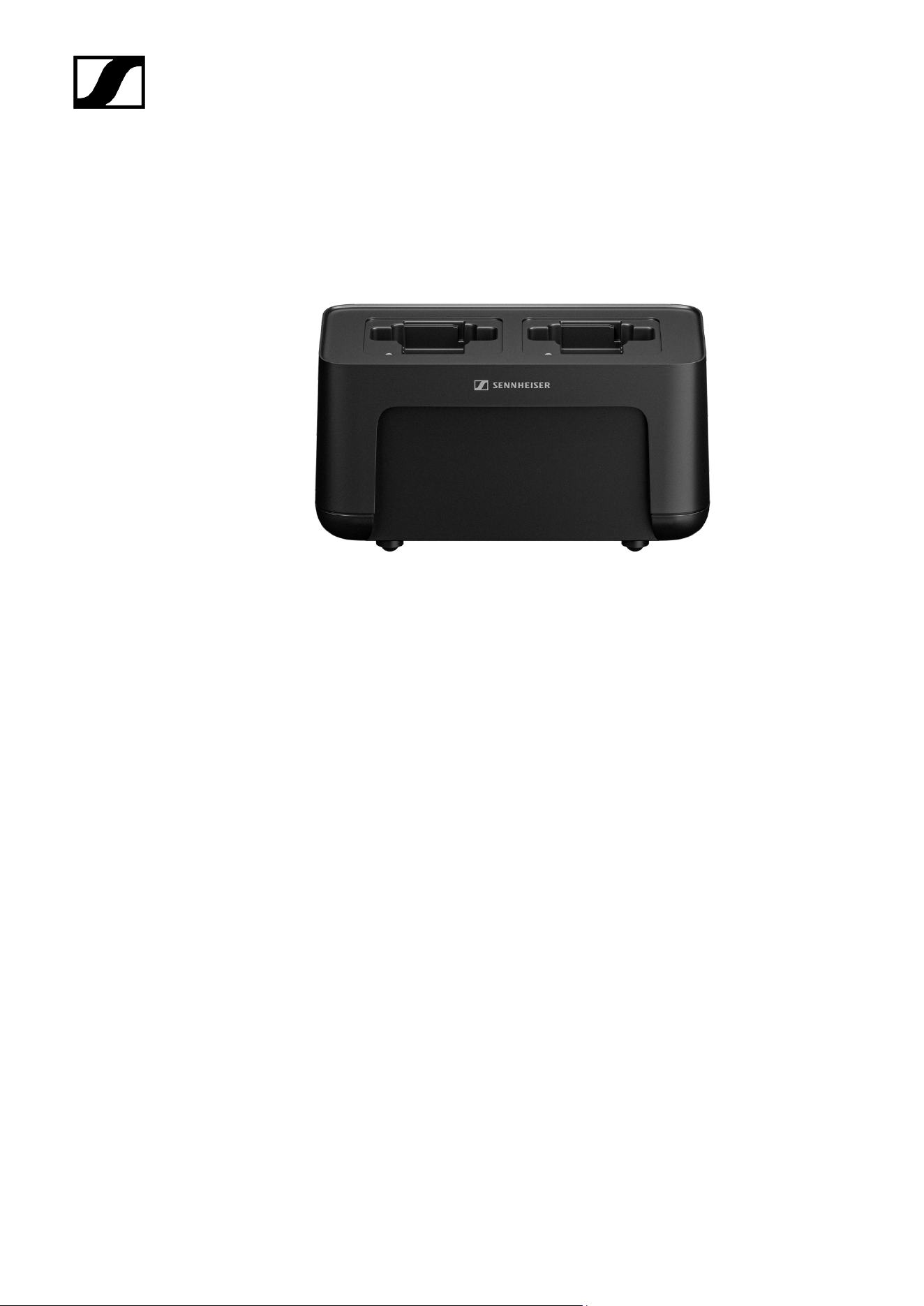
CHG 70N-C network-enabled charger..........................................................................63
EW-D ASA antenna splitter............................................................................................65
EW-D AB antenna booster............................................................................................. 66
Antennas............................................................................................................................67
Accessories for rack mounting....................................................................................... 71
Mounting accessories for EW-DP EK............................................................................73
Cables for EW-DP EK...................................................................................................... 74
Color Coding Sets............................................................................................................ 75
Frequency ranges.................................................................................................................... 76
3. Instruction manual......................................................................................................................79
EW-D EM rack receiver.......................................................................................................... 79
Product overview..............................................................................................................79
Connecting/disconnecting the receiver to/from the power supply system.............81
Connecting antennas.......................................................................................................83
Outputting audio signals.................................................................................................85
Installing receivers in a rack.......................................................................................... 86
Switching the receiver on and off................................................................................. 89
Lock-off function..............................................................................................................90
Meaning of the LEDs....................................................................................................... 91
Displays on the receiver’s display panel...................................................................... 93
Buttons for navigating the menu................................................................................... 95
Opening the menu and navigating the menu items.................................................... 96
Using EW-D Color Coding Sets to label transmission paths....................................105
EW-D SKM-S handheld transmitter.................................................................................... 106
Product overview............................................................................................................106
Inserting and removing the batteries/rechargeable batteries................................. 107
Replacing the microphone module.............................................................................. 109
Using EW-D Color Coding Sets to label transmission paths..................................... 111
Switching the handheld transmitter on and off.......................................................... 112
Checking the battery status of the transmitter (Check function)............................. 113
Identifying the paired receiver (Identify function)...................................................... 114
Meaning of the LEDs...................................................................................................... 115
Establishing a connection to the receiver................................................................... 118
Muting the handheld transmitter..................................................................................119

EW-D SK bodypack transmitter...........................................................................................120
Product overview............................................................................................................ 120
Inserting and removing the batteries/rechargeable batteries..................................121
Connecting a microphone to the bodypack transmitter........................................... 123
Connecting an instrument or line source to the bodypack transmitter...................125
Using EW-D Color Coding Sets to label transmission paths....................................126
Changing the belt clip....................................................................................................127
Switching the bodypack transmitter on and off.........................................................128
Checking the battery status of the transmitter (Check function)............................ 129
Identifying the paired receiver (Identify function)..................................................... 130
Meaning of the LEDs...................................................................................................... 131
Establishing a connection to the receiver.................................................................. 134
Muting the bodypack transmitter................................................................................ 135
EW-DX EM 2 rack receiver...................................................................................................136
Product overview............................................................................................................ 136
Connecting/disconnecting the receiver to/from the power supply system...........139
Connecting receivers in a network.............................................................................. 142
Connecting antennas..................................................................................................... 143
Outputting audio signals............................................................................................... 145
Installing receivers in a rack.........................................................................................147
Switching the receiver on and off................................................................................150
Lock-off function............................................................................................................. 151
Using the headphone output........................................................................................ 152
Meaning of the LEDs..................................................................................................... 153
Displays on the receiver’s display panel.....................................................................155
Buttons for navigating the menu................................................................................. 165
Opening the menu and navigating the menu items.................................................. 166
Menu structure................................................................................................................167
Setting options in the menu......................................................................................... 168
System menu item......................................................................................................... 194
Updating the firmware of the receiver....................................................................... 206
EW-DX EM 2 Dante rack receiver....................................................................................... 207
Product overview............................................................................................................207
Connecting/disconnecting the receiver to/from the power supply system...........210
Connecting receivers in a network.............................................................................. 213
Connecting receivers in a Dante® network.................................................................214
Connecting antennas.....................................................................................................220

Outputting audio signals...............................................................................................222
Installing receivers in a rack........................................................................................ 224
Switching the receiver on and off................................................................................227
Lock-off function............................................................................................................ 228
Using the headphone output........................................................................................229
Meaning of the LEDs.....................................................................................................230
Displays on the receiver’s display panel.................................................................... 232
Buttons for navigating the menu................................................................................. 242
Opening the menu and navigating the menu items.................................................. 243
Menu structure...............................................................................................................244
Setting options in the menu.........................................................................................245
System menu item..........................................................................................................271
Updating the firmware of the receiver....................................................................... 284
EW-DX EM 4 Dante rack receiver.......................................................................................285
Product overview........................................................................................................... 285
Connecting/disconnecting the receiver to/from the power supply system.......... 289
Connecting receivers in a network............................................................................. 290
Connecting receivers in a Dante® network.................................................................291
Connecting antennas.................................................................................................... 296
Outputting audio signals.............................................................................................. 299
Installing receivers in a rack.........................................................................................301
Switching the receiver on and off...............................................................................304
Lock-off function............................................................................................................305
Using the headphone output....................................................................................... 306
Meaning of the LEDs.....................................................................................................307
Displays on the receiver’s display panel.................................................................... 309
Buttons for navigating the menu................................................................................. 318
Opening the menu and navigating the menu items...................................................319
Menu structure...............................................................................................................320
Setting options in the menu......................................................................................... 321
System menu item.........................................................................................................347
Updating the firmware of the receiver....................................................................... 360
EW-DX SKM | EW-DX SKM-S handheld transmitter......................................................... 361
Product overview............................................................................................................ 361
Inserting and removing the batteries/rechargeable batteries................................ 363
Replacing the microphone module............................................................................. 365
Switching the handheld transmitter on and off.........................................................367

Checking the battery status of the transmitter (Check function)............................368
Identifying the paired receiver (Identify function).....................................................369
Meaning of the LEDs.....................................................................................................370
Establishing a connection to the receiver.................................................................. 373
Information on the handheld transmitter’s display................................................... 374
Buttons for navigating the menu................................................................................. 376
Opening the menu and navigating the menu items.................................................. 377
Lock-off function............................................................................................................389
Configuring mute mode and muting the handheld transmitter (EW-DX SKM-S
only)................................................................................................................................. 390
Updating the firmware of the transmitter.................................................................. 392
EW-DX SK | EW-DX SK 3-PIN bodypack transmitter....................................................... 393
Product overview........................................................................................................... 393
Inserting and removing the batteries/rechargeable batteries................................ 395
Connecting a microphone to the bodypack transmitter........................................... 397
Connecting an instrument or line source to the bodypack transmitter..................400
Changing the belt clip...................................................................................................402
Switching the bodypack transmitter on and off........................................................403
Checking the battery status of the transmitter (Check function)........................... 404
Identifying the paired receiver (Identify function).....................................................405
Meaning of the LEDs.................................................................................................... 406
Establishing a connection to the receiver..................................................................409
Information on the bodypack transmitter’s display...................................................410
Buttons for navigating the menu..................................................................................412
Opening the menu and navigating the menu items...................................................413
Lock-off function............................................................................................................426
Configuring mute mode and muting the bodypack transmitter...............................427
Updating the firmware of the transmitter.................................................................. 428
Table stand EW-DX TS 3-pin | EW-DX TS 5-pin............................................................... 429
Product overview........................................................................................................... 429
Inserting and removing the BA 40 rechargeable battery..........................................431
Charging the table stand..............................................................................................432
Meaning of the LEDs.....................................................................................................434
Connecting a gooseneck microphone........................................................................ 436
Switching the table stand on/off.................................................................................437
Establishing a connection to the receiver..................................................................438
Muting the table stand................................................................................................. 439

EW-DP EK portable receiver............................................................................................... 440
Product overview........................................................................................................... 440
Power supply.................................................................................................................. 442
Outputting audio signals.............................................................................................. 444
Mounting the receiver / mounting options................................................................ 445
Switching the receiver on and off............................................................................... 454
Meaning of the LEDs.....................................................................................................455
Displays on the receiver’s display panel.................................................................... 457
Buttons for navigating the menu.................................................................................459
Opening the menu and navigating the menu items..................................................460
EW-DP SKP plug-on transmitter.........................................................................................469
Product overview........................................................................................................... 469
Power supply.................................................................................................................. 472
Using a microSD card................................................................................................... 474
Attaching an XLR microphone..................................................................................... 476
Connecting a lavalier microphone............................................................................... 477
Switching the plug-on transmitter on and off........................................................... 478
Starting/stopping recording.........................................................................................479
Activating/deactivating the low-cut filter..................................................................480
MUTE mode.....................................................................................................................481
Meaning of the LEDs.....................................................................................................482
Establishing a radio link | Synchronizing the receiver and transmitter..........................485
Connecting to the EW-D EM receiver / synchronizing the EW-D EM.................... 486
Connecting to the EW-DX EM receivers / synchronizing the EW-DX EM..............488
Connecting to the EW-DP EK receiver / synchronizing the EW-DP EK..................490
L 70 USB charger.................................................................................................................. 492
Connecting/disconnecting the charger to/from the power supply system...........492
Charging the rechargeable battery............................................................................. 493
CHG 70N-C charger..............................................................................................................495
Product overview........................................................................................................... 495
Connecting/disconnecting the charger to/from the power supply system...........497
Connecting a charger in a network............................................................................ 499
Cascading chargers....................................................................................................... 501
Charging the rechargeable battery............................................................................. 503
Power saving mode....................................................................................................... 505
EW-D ASA antenna splitter................................................................................................. 506
Product overview........................................................................................................... 506

Connecting/disconnecting the EW-D ASA to/from the power supply system..... 508
Connecting receivers to the EW-D ASA.....................................................................509
Connecting antennas..................................................................................................... 510
Information on antenna amplifiers and cable lengths............................................... 511
Configuring multi-channel systems............................................................................. 512
Installing the EW-D ASA in a rack...............................................................................514
Switching the EW-D ASA on and off...........................................................................515
AWM active directional antenna......................................................................................... 516
Product overview............................................................................................................ 516
Antenna setup.................................................................................................................519
Connecting the cable to the antenna......................................................................... 520
Recommended cable lengths....................................................................................... 522
Installing and mounting the antenna.......................................................................... 523
Setting the gain............................................................................................................. 530
GAIN LED.........................................................................................................................531
Cleaning and maintenance...................................................................................................532
4. Knowledge base....................................................................................................................... 534
FAQ.......................................................................................................................................... 534
Radio and frequencies.................................................................................................. 534
Audio................................................................................................................................536
Usability...........................................................................................................................538
Accessories..................................................................................................................... 541
Smart Assist app........................................................................................................... 543
5. Specifications............................................................................................................................545
System.................................................................................................................................... 545
EW-D EM rack receiver........................................................................................................ 547
EW-DX EM 2 rack receiver.................................................................................................. 548
EW-DX EM 2 Dante rack receiver.......................................................................................549
EW-DX EM 4 Dante rack receiver...................................................................................... 550
EW-D SKM-S handheld transmitter.................................................................................... 551
EW-DX SKM | EW-DX SKM-S handheld transmitter........................................................ 552
EW-D SK bodypack transmitter.......................................................................................... 553
EW-DX SK | EW-DX SK 3-PIN bodypack transmitter....................................................... 554
Table stand EW-DX TS 3-pin | EW-DX TS 5-pin............................................................... 555
EW-DP EK portable receiver................................................................................................556
EW-DP SKP plug-on transmitter receiver.......................................................................... 557
EW-D ASA antenna splitter................................................................................................. 558

EW-D AB antenna booster...................................................................................................560
AWM active directional antenna......................................................................................... 561
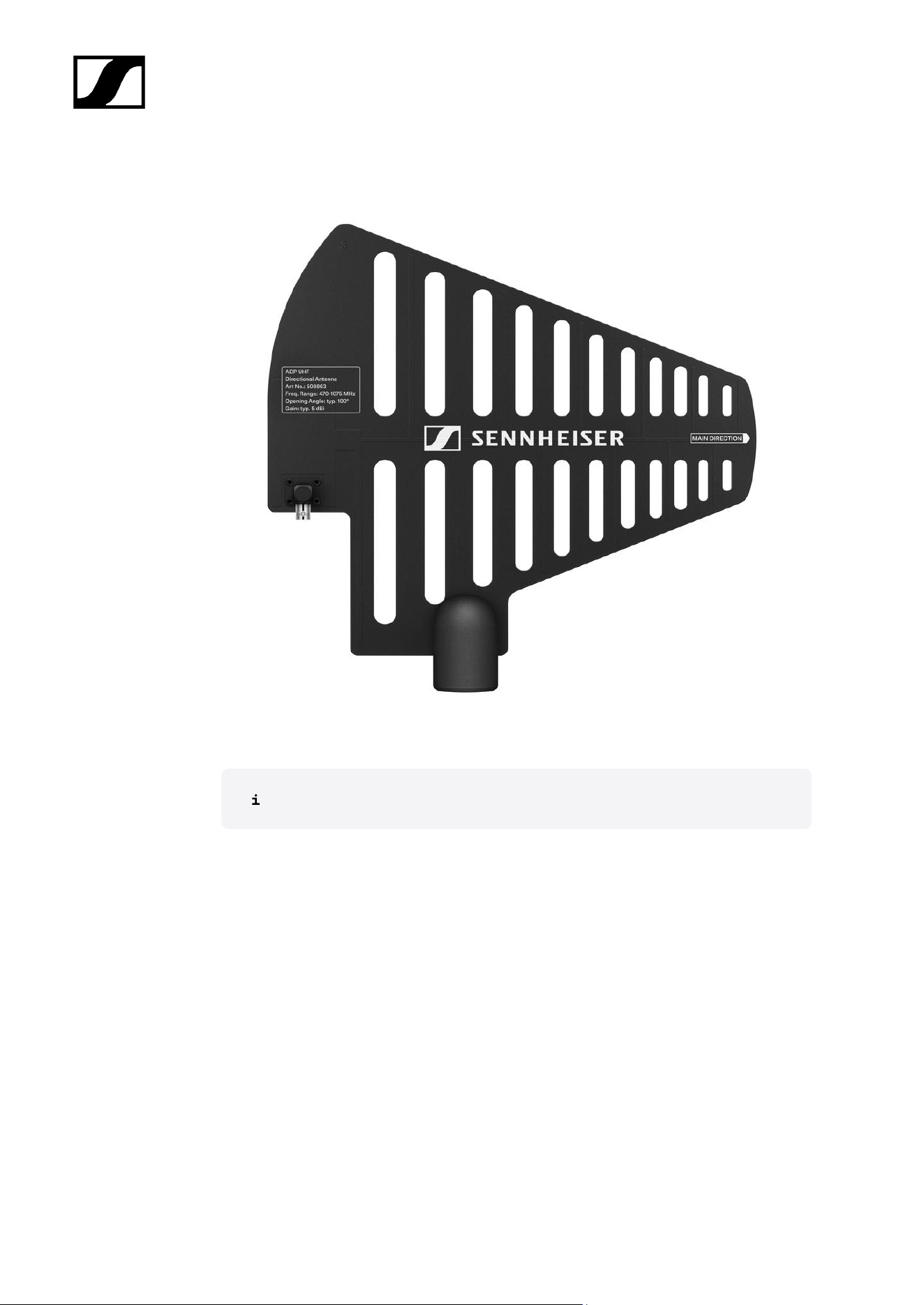
ADP UHF passive directional antenna (470 – 1075 MHz).................................................568
BA 70 rechargeable battery................................................................................................. 570
L 70 USB charger................................................................................................................... 571
CHG 70N-C charger.............................................................................................................. 572
6. Contact.......................................................................................................................................574

Evolution Wireless Digital
1. Preface
PDF export of the original HTML instructions
This PDF document is an automated export of an interactive set of HTML instructions.
It may be the case that not all contents and interactive elements are contained in the
PDF as they cannot be presented in this format. Furthermore, automatically generated
page breaks may cause coherent contents to be moved slightly. We can therefore only
guarantee the completeness of the information in the HTML instructions, and recommend
that you use these. You can find this in the documentation portal at www.sennheiser.com/
documentation.
10
Evolution Wireless Digital
2. Product information
All information about the product and available accessories at a glance.
Products of the EW-D series
For information about the available accessories, see Accessories.
For information about the available sets, see Sets available for the EW-D series.
For information about the frequency ranges, see Frequency ranges.
You can find technical specifications for the series and the individual products under
Specifications.
You can find information about starting up and operating the products under Instruction
manual.
EW-D EM rack receiver
The EW-D EM rack receiver is available in the following versions:
11

| 2 - Product information
EW-D EM (Q1–6) | 470.2 – 526 MHz | Art. no. 508800
EW-D EM (R1–6) | 520 – 576 MHz | Art. no. 508801
EW-D EM (R4–9) | 552 – 607.8 MHz | Art. no. 508802
EW-D EM (S1–7) | 606.2 – 662 MHz | Art. no. 508803
EW-D EM (S4–7) | 630 – 662 MHz | Art. no. 508804
EW-D EM (S7–10) | 662 – 693.8 MHz | Art. no. 508805
EW-D EM (T1/7) | 694,5 - 702,7 MHz & 748,3 - 757,7 MHz | Art. no. 700458
EW-D EM (T12) | 806,125 - 809,75 MHz | Art. no. 700459
EW-D EM (T13-14) | 819,2 - 823 MHz | Art. no. 700460
EW-D EM (U1/5) | 823.2 – 831.8 MHz & 863.2 – 864.8 MHz | Art. no. 508806
EW-D EM (V3–4) | 925.2 – 937.3 MHz | Art. no. 508808
EW-D EM (Y1–3) | 1785.2 – 1799.8 MHz | Art. no. 508809
You can find more detailed information about the EW-D EM in the following
sections:
• Startup and operation: EW-D EM rack receiver
• Specifications: EW-D EM rack receiver
12
| 2 - Product information
EW-D SKM-S handheld transmitter
The EW-D SKM-S handheld transmitter is available in the following versions:
EW-D SKM-S (Q1–6) | 470.2 – 526 MHz | Art. no. 508790
EW-D SKM-S (R1–6) | 520 – 576 MHz | Art. no. 508791
EW-D SKM-S (R4–9) | 552 – 607.8 MHz | Art. no. 508792
EW-D SKM-S (S1–7) | 606.2 – 662 MHz | Art. no. 508793
EW-D SKM-S (S4–7) | 630 – 662 MHz | Art. no. 508794
EW-D SKM-S (S7–10) | 662 – 693.8 MHz | Art. no. 508795
EW-D SKM-S (T1/7) | 694,5 - 702,7 MHz & 748,3 - 757,7 MHz | Art. no. 700458
EW-D SKM-S (T12) | 806,125 - 809,75 MHz | Art. no. 700456
EW-D SKM-S (T13-14) | 819,2 - 823 MHz | Art. no. 700457
EW-D SKM-S (U1/5) | 823.2 – 831.8 MHz & 863.2 – 864.8 MHz | Art. no. 508796
EW-D SKM-S (V3–4) | 925.2 – 937.3 MHz | Art. no. 508798
EW-D SKM-S (Y1–3) | 1785.2 – 1799.8 MHz | Art. no. 508799
You can find more detailed information about the EW-D SKM-S in the following
sections:
• Startup and operation: EW-D SKM-S handheld transmitter
• Specifications: EW-D SKM-S handheld transmitter
• Compatible microphone modules: Replacing the microphone module
13
| 2 - Product information
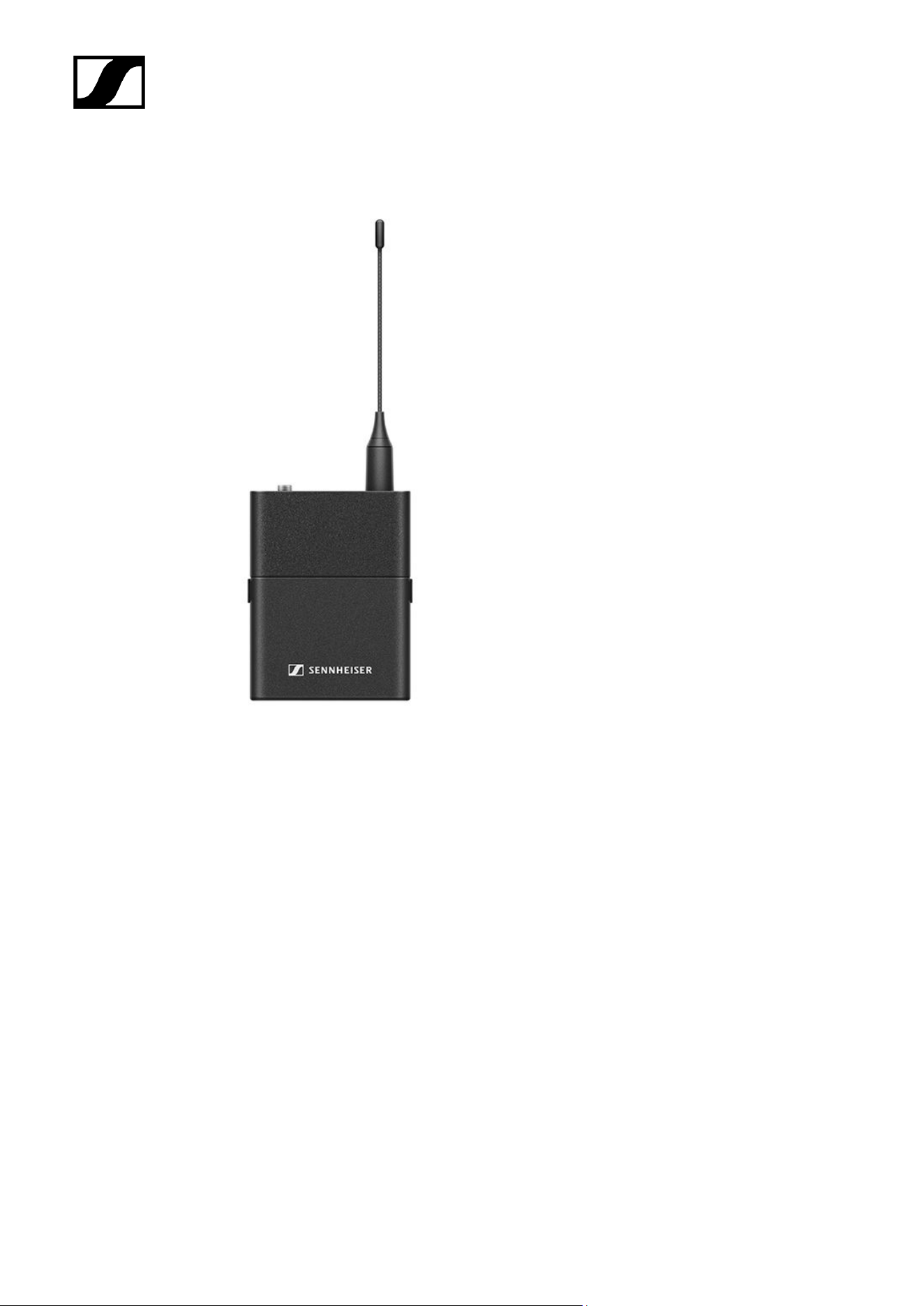
EW-D SK bodypack transmitter
The EW-D SK bodypack transmitter is available in the following versions:
EW-D SK (Q1–6) | 470.2 – 526 MHz | Art. no. 508780
EW-D SK (R1–6) | 520 – 576 MHz | Art. no. 508781
EW-D SK (R4–9) | 552 – 607.8 MHz | Art. no. 508782
EW-D SK (S1–7) | 606.2 – 662 MHz | Art. no. 508783
EW-D SK (S4–7) | 630 – 662 MHz | Art. no. 508784
EW-D SK (S7–10) | 662 – 693.8 MHz | Art. no. 508785
EW-D SK (T1/7) | 694,5 - 702,7 MHz & 748,3 - 757,7 MHz | Art. no. 700452
EW-D SK (T12) | 806,125 - 809,75 MHz | Art. no. 700453
EW-D SK (T13-14) | 819,2 - 823 MHz | Art. no. 700454
EW-D SK (U1/5) | 823.2 – 831.8 MHz & 863.2 – 864.8 MHz | Art. no. 508786
EW-D SK (V3–4) | 925.2 – 937.3 MHz | Art. no. 508788
EW-D SK (Y1–3) | 1785.2 – 1799.8 MHz | Art. no. 508789
14

| 2 - Product information
Sets available for the EW-D series
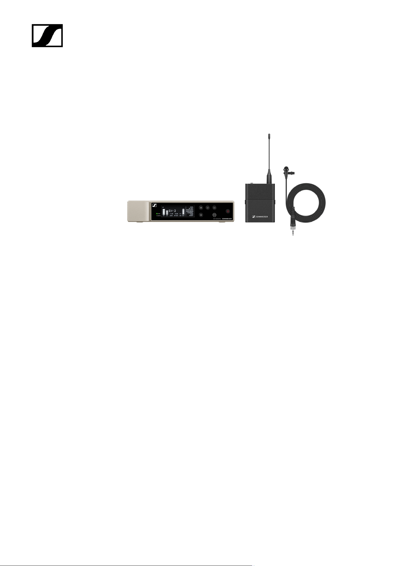
EW-D ME2 SET | Lavalier Set
The set consists of the following components:
• EW-D EM rack receiver
• EW-D SK bodypack transmitter
• ME 2 lavalier microphone
The set is available in the following versions:
EW-D ME2 SET (Q1–6) | 470.2 – 526 MHz | Art. no. 508700
EW-D ME2 SET (R1–6) | 520 – 576 MHz | Art. no. 508701
EW-D ME2 SET (R4–9) | 552 – 607.8 MHz | Art. no. 508702
EW-D ME2 SET (S1–7) | 606.2 – 662 MHz | Art. no. 508703
EW-D ME2 SET (S4–7) | 630 – 662 MHz | Art. no. 508704
EW-D ME2 SET (S7–10) | 662 – 693.8 MHz | Art. no. 508705
EW-D ME2 SET (T1/7) | 694,5 - 702,7 MHz & 748,3 - 757,7 MHz | Art. no. 700428
EW-D ME2 SET (T12) | 806,125 - 809,75 MHz | Art. no. 700429
EW-D ME2 SET (T13-14) | 819,2 - 823 MHz | Art. no. 700430
EW-D ME2 SET (U1/5) | 823.2 – 831.8 MHz & 863.2 – 864.8 MHz | Art. no. 508706
EW-D ME2 SET (V3–4) | 925.2 – 937.3 MHz | Art. no. 508708
EW-D ME2 SET (Y1–3) | 1785.2 – 1799.8 MHz | Art. no. 508709
16

| 2 - Product information
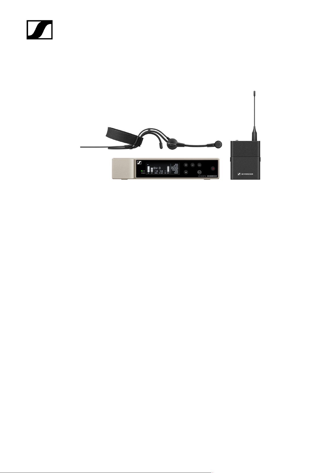
EW-D ME3 SET | Headmic Set
The set consists of the following components:
• EW-D EM rack receiver
• EW-D SK bodypack transmitter
• ME 3 lavalier microphone
The set is available in the following versions:
EW-D ME3 SET (Q1–6) | 470.2 – 526 MHz | Art. no. 508710
EW-D ME3 SET (R1–6) | 520 – 576 MHz | Art. no. 508711
EW-D ME3 SET (R4–9) | 552 – 607.8 MHz | Art. no. 508712
EW-D ME3 SET (S1–7) | 606.2 – 662 MHz | Art. no. 508713
EW-D ME3 SET (S4–7) | 630 – 662 MHz | Art. no. 508714
EW-D ME3 SET (S7–10) | 662 – 693.8 MHz | Art. no. 508715
EW-D ME3 SET (T1/7) | 694,5 - 702,7 MHz & 748,3 - 757,7 MHz | Art. no. 700431
EW-D ME3 SET (T12) | 806,125 - 809,75 MHz | Art. no. 700432
EW-D ME3 SET (T13-14) | 819,2 - 823 MHz | Art. no. 700433
EW-D ME3 SET (U1/5) | 823.2 – 831.8 MHz & 863.2 – 864.8 MHz | Art. no. 508716
EW-D ME3 SET (V3–4) | 925.2 – 937.3 MHz | Art. no. 508718
EW-D ME3 SET (Y1–3) | 1785.2 – 1799.8 MHz | Art. no. 508719
18

| 2 - Product information
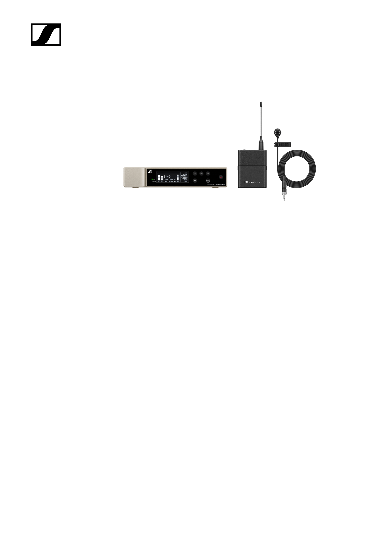
EW-D ME4 SET | Lavalier Set
The set consists of the following components:
• EW-D EM rack receiver
• EW-D SK bodypack transmitter
• ME 4 lavalier microphone
The set is available in the following versions:
EW-D ME4 SET (Q1–6) | 470.2 – 526 MHz | Art. no. 508720
EW-D ME4 SET (R1–6) | 520 – 576 MHz | Art. no. 508721
EW-D ME4 SET (R4–9) | 552 – 607.8 MHz | Art. no. 508722
EW-D ME4 SET (S1–7) | 606.2 – 662 MHz | Art. no. 508723
EW-D ME4 SET (S4–7) | 630 – 662 MHz | Art. no. 508724
EW-D ME4 SET (S7–10) | 662 – 693.8 MHz | Art. no. 508725
EW-D ME4 SET (T1/7) | 694,5 - 702,7 MHz & 748,3 - 757,7 MHz | Art. no. 700434
EW-D ME4 SET (T12) | 806,125 - 809,75 MHz | Art. no. 700435
EW-D ME4 SET (T13-14) | 819,2 - 823 MHz | Art. no. 700436
EW-D ME4 SET (U1/5) | 823.2 – 831.8 MHz & 863.2 – 864.8 MHz | Art. no. 508726
EW-D ME4 SET (V3–4) | 925.2 – 937.3 MHz | Art. no. 508728
EW-D ME4 SET (Y1–3) | 1785.2 – 1799.8 MHz | Art. no. 508729
20


| 2 - Product information
EW-D Cl1 SET | Instrument Set
The set consists of the following components:
• EW-D EM rack receiver
• EW-D SK bodypack transmitter
• Cl 1 lavalier microphone
The set is available in the following versions:
EW-D Cl1 SET (Q1–6) | 470.2 – 526 MHz | Art. no. 508730
EW-D Cl1 SET (R1–6) | 520 – 576 MHz | Art. no. 508731
EW-D Cl1 SET (R4–9) | 552 – 607.8 MHz | Art. no. 508732
EW-D Cl1 SET (S1–7) | 606.2 – 662 MHz | Art. no. 508733
EW-D Cl1 SET (S4–7) | 630 – 662 MHz | Art. no. 508734
EW-D Cl1 SET (S7–10) | 662 – 693.8 MHz | Art. no. 508735
EW-D Cl1 SET (T1/7) | 694,5 - 702,7 MHz & 748,3 - 757,7 MHz | Art. no. 700437
EW-D Cl1 SET (T12) | 806,125 - 809,75 MHz | Art. no. 700438
EW-D Cl1 SET (T13-14) | 819,2 - 823 MHz | Art. no. 700439
EW-D Cl1 SET (U1/5) | 823.2 – 831.8 MHz & 863.2 – 864.8 MHz | Art. no. 508736
EW-D Cl1 SET (V3–4) | 925.2 – 937.3 MHz | Art. no. 508738
EW-D Cl1 SET (Y1–3) | 1785.2 – 1799.8 MHz | Art. no. 508739
22

| 2 - Product information
EW-D SK BASE SET | Base Set
The set consists of the following components:
• EW-D EM rack receiver
• EW-D SK bodypack transmitter
The set is available in the following versions:
EW-D SK BASE SET (Q1–6) | 470.2 – 526 MHz | Art. no. 508740
EW-D SK BASE SET (R1–6) | 520 – 576 MHz | Art. no. 508741
EW-D SK BASE SET (R4–9) | 552 – 607.8 MHz | Art. no. 508742
EW-D SK BASE SET (S1–7) | 606.2 – 662 MHz | Art. no. 508743
EW-D SK BASE SET (S4–7) | 630 – 662 MHz | Art. no. 508744
EW-D SK BASE SET (S7–10) | 662 – 693.8 MHz | Art. no. 508745
EW-D SK BASE SET (T1/7) | 694,5 - 702,7 MHz & 748,3 - 757,7 MHz | Art. no. 700440
EW-D SK BASE SET (T12) | 806,125 - 809,75 MHz | Art. no. 700441
EW-D SK BASE SET (T13-14) | 819,2 - 823 MHz | Art. no. 700442
EW-D SK BASE SET (U1/5) | 823.2 – 831.8 MHz & 863.2 – 864.8 MHz | Art. no. 508746
EW-D SK BASE SET (V3–4) | 925.2 – 937.3 MHz | Art. no. 508748
EW-D SK BASE SET (Y1–3) | 1785.2 – 1799.8 MHz | Art. no. 508749
24

| 2 - Product information
EW-D 835-S SET | Handheld Set
The set consists of the following components:
• EW-D EM rack receiver
• EW-D SKM-S handheld transmitter
• MMD 835 microphone module
The set is available in the following versions:
EW-D 835-S SET (Q1–6) | 470.2 – 526 MHz | Art. no. 508750
EW-D 835-S SET (R1–6) | 520 – 576 MHz | Art. no. 508751
EW-D 835-S SET (R4–9) | 552 – 607.8 MHz | Art. no. 508752
EW-D 835-S SET (S1–7) | 606.2 – 662 MHz | Art. no. 508753
EW-D 835-S SET (S4–7) | 630 – 662 MHz | Art. no. 508754
EW-D 835-S SET (S7–10) | 662 – 693.8 MHz | Art. no. 508755
EW-D 835-S SET (T1/7) | 694,5 - 702,7 MHz & 748,3 - 757,7 MHz | Art. no. 700443
EW-D 835-S SET (T12) | 806,125 - 809,75 MHz | Art. no. 700444
EW-D 835-S SET (T13-14) | 819,2 - 823 MHz | Art. no. 700445
EW-D 835-S SET (U1/5) | 823.2 – 831.8 MHz & 863.2 – 864.8 MHz | Art. no. 508756
EW-D 835-S SET (V3–4) | 925.2 – 937.3 MHz | Art. no. 508758
EW-D 835-S SET (Y1–3) | 1785.2 – 1799.8 MHz | Art. no. 508759
26

| 2 - Product information
EW-D SKM-S BASE SET | Base Set
The set consists of the following components:
• EW-D EM rack receiver
• EW-D SKM-S handheld transmitter
The set is available in the following versions:
EW-D SKM-S BASE SET (Q1–6) | 470.2 – 526 MHz | Art. no. 508740
EW-D SKM-S BASE SET (R1–6) | 520 – 576 MHz | Art. no. 508741
EW-D SKM-S BASE SET (R4–9) | 552 – 607.8 MHz | Art. no. 508742
EW-D SKM-S BASE SET (S1–7) | 606.2 – 662 MHz | Art. no. 508743
EW-D SKM-S BASE SET (S4–7) | 630 – 662 MHz | Art. no. 508744
EW-D SKM-S BASE SET (S7–10) | 662 – 693.8 MHz | Art. no. 508745
EW-D SKM-S BASE SET (T1/7) | 694,5 - 702,7 MHz & 748,3 - 757,7 MHz | Art. no. 700446
EW-D SKM-S BASE SET (T12) | 806,125 - 809,75 MHz | Art. no. 700447
EW-D SKM-S BASE SET (T13-14) | 819,2 - 823 MHz | Art. no. 700448
EW-D SKM-S BASE SET (U1/5) | 823.2 – 831.8 MHz & 863.2 – 864.8 MHz | Art. no. 508746
EW-D SKM-S BASE SET (V3–4) | 925.2 – 937.3 MHz | Art. no. 508748
EW-D SKM-S BASE SET (Y1–3) | 1785.2 – 1799.8 MHz | Art. no. 508749
28

| 2 - Product information
EW-D ME2/835-S SET | Combo Set
The set consists of the following components:
• EW-D EM rack receiver
• EW-D SK bodypack transmitter
• EW-D SKM-S handheld transmitter
• ME 2 lavalier microphone
• MMD 835 microphone module
The set is available in the following versions:
EW-D ME2/835-S SET (Q1–6) | 470.2 – 526 MHz | Art. no. 508770
EW-D ME2/835-S SET (R1–6) | 520 – 576 MHz | Art. no. 508771
EW-D ME2/835-S SET (R4–9) | 552 – 607.8 MHz | Art. no. 508772
EW-D ME2/835-S SET (S1–7) | 606.2 – 662 MHz | Art. no. 508773
EW-D ME2/835-S SET (S4–7) | 630 – 662 MHz | Art. no. 508774
EW-D ME2/835-S SET (S7–10) | 662 – 693.8 MHz | Art. no. 508775
EW-D ME2/835-S SET (T1/7) | 694,5 - 702,7 MHz & 748,3 - 757,7 MHz | Art. no. 700446
EW-D ME2/835-S SET (T12) | 806,125 - 809,75 MHz | Art. no. 700447
EW-D ME2/835-S SET (T13-14) | 819,2 - 823 MHz | Art. no. 700448
EW-D ME2/835-S SET (U1/5) | 823.2 – 831.8 MHz & 863.2 – 864.8 MHz | Art. no. 508776
EW-D ME2/835-S SET (V3–4) | 925.2 – 937.3 MHz | Art. no. 508778
EW-D ME2/835-S SET (Y1–3) | 1785.2 – 1799.8 MHz | Art. no. 508779
30

| 2 - Product information
Products of the EW-DX series
For information about the available accessories, see Accessories.
For information about the available sets, see Sets available for the EW-DX series.
For information about the frequency ranges, see Frequency ranges.
You can find technical specifications for the series and the individual products under
Specifications.
You can find information about starting up and operating the products under Instruction
manual.
EW-DX EM 2 rack receiver
The EW-DX EM 2 rack receiver is available in the following versions:
EW-DX EM 2 (Q1–9) | 470.2 – 550 MHz | Art. no. 509342
EW-DX EM 2 (R1–9) | 520 – 607.8 MHz | Art. no. 509343
EW-DX EM 2 (S1–10) | 606.2 – 693.8 MHz | Art. no. 509344
EW-DX EM 2 (S2–10) | 614.2 – 693.8 MHz | Art. no. 509347
32

| 2 - Product information
EW-DX EM 2 (S4–10) | 630 – 693.8 MHz | Art. no. 509348
EW-DX EM 2 (U1/5) | 823.2 – 831.8 MHz & 863.2 – 864.8 MHz | Art. no. 509349
EW-DX EM 2 (V3–4) | 925.2 – 937.3 MHz | Art. no. 509351
EW-DX EM 2 (V5–7) | 941.7 – 951.8 MHz & 953.05 – 956.05 MHz & 956.65 – 959.65 MHz |
Art. no. 509352
EW-DX EM 2 (Y1–3) | 1785.2 – 1799.8 MHz | Art. no. 509355
You can find more detailed information about the EW-DX EM 2 in the following
sections:
• Startup and operation: EW-DX EM 2 rack receiver
• Specifications: EW-DX EM 2 rack receiver
33
| 2 - Product information
EW-DX EM 2 Dante rack receiver
The EW-DX EM 2 Dante rack receiver is available in the following versions:
EW-DX EM 2 Dante (Q1–9) | 470.2 – 550 MHz | Art. no. 509356
EW DX EM 2 Dante (R1–9) | 520 – 607.8 MHz | Art. no. 509357
EW DX EM 2 Dante (S1–10) | 606.2 – 693.8 MHz | Art. no. 509358
EW DX EM 2 Dante (S2–10) | 614.2 – 693.8 MHz | Art. no. 509361
EW DX EM 2 Dante (S4–10) | 630 – 693.8 MHz | Art. no. 509362
EW-DX EM 2 Dante (U1/5) | 823.2 – 831.8 MHz & 863.2 – 864.8 MHz | Art. no. 509363
EW DX EM 2 Dante (V3–4) | 925.2 – 937.3 MHz | Art. no. 509365
EW-DX EM 2 Dante (V5–7) | 941.7 – 951.8 MHz & 953.05 – 956.05 MHz & 956.65 – 959.65
MHz | Art. no. 509366
EW DX EM 2 Dante (Y1–3) | 1785.2 – 1799.8 MHz | Art. no. 509369
You can find more detailed information about the EW-DX EM 2 Dante in the
following sections:
• Startup and operation: EW-DX EM 2 Dante rack receiver
• Specifications: EW-DX EM 2 Dante rack receiver
34
| 2 - Product information
EW-DX EM 4 Dante rack receiver
The EW-DX EM 4 Dante rack receiver is available in the following versions:
EW-DX EM 4 Dante (Q1–9) | 470.2 – 550 MHz | Art. no. 509370
EW DX EM 4 Dante (R1–9) | 520 – 607.8 MHz | Art. no. 509371
EW DX EM 4 Dante (S1–10) | 606.2 – 693.8 MHz | Art. no. 509372
EW DX EM 4 Dante (S2–10) | 614.2 – 693.8 MHz | Art. no. 509375
EW DX EM 4 Dante (S4–10) | 630 – 693.8 MHz | Art. no. 509376
EW-DX EM 4 Dante (U1/5) | 823.2 – 831.8 MHz & 863.2 – 864.8 MHz | Art. no. 509377
EW DX EM 4 Dante (V3–4) | 925.2 – 937.3 MHz | Art. no. 509379
EW-DX EM 4 Dante (V5–7) | 941.7 – 951.8 MHz & 953.05 – 956.05 MHz & 956.65 – 959.65
MHz | Art. no. 509380
EW DX EM 4 Dante (Y1–3) | 1785.2 – 1799.8 MHz | Art. no. 509383
You can find more detailed information about the EW-DX EM 4 Dante in the
following sections:
• Startup and operation: EW-DX EM 4 Dante rack receiver
• Specifications: EW-DX EM 4 Dante rack receiver
35
| 2 - Product information
EW-DX SKM | EW-DX SKM-S handheld transmitter
Handheld transmitter without mute switch
The EW-DX SKM handheld transmitter without mute switch is available in the following
versions:
EW-DX SKM (Q1–9) | 470.2 – 550 MHz | Art. no. 509426
EW-DX SKM (R1–9) | 520 – 607.8 MHz | Art. no. 509427
EW-DX SKM (S1–10) | 606.2 – 693.8 MHz | Art. no. 509428
EW-DX SKM (S2–10) | 614.2 – 693.8 MHz | Art. no. 509431
EW-DX SKM (S4–10) | 630 – 693.8 MHz | Art. no. 509432
EW-DX SKM (U1/5) | 823.2 – 831.8 MHz & 863.2 – 864.8 MHz | Art. no. 509433
EW-DX SKM (V3–4) | 925.2 – 937.3 MHz | Art. no. 509435
EW-DX SKM (V5–7) | 941.7 – 951.8 MHz & 953.05 – 956.05 MHz & 956.65 – 959.65 MHz |
Art. no. 509436
EW-DX SKM (Y1–3) | 1785.2 – 1799.8 MHz | Art. no. 509439
36

| 2 - Product information
Handheld transmitter with mute switch
The EW-DX SKM-S handheld transmitter with mute switch is available in the following
versions:
EW-DX SKM-S (Q1–9) | 470.2 – 550 MHz | Art. no. 509412
EW-DX SKM-S (R1–9) | 520 – 607.8 MHz | Art. no. 509413
EW-DX SKM-S (S1–10) | 606.2 – 693.8 MHz | Art. no. 509414
EW-DX SKM-S (S2–10) | 614.2 – 693.8 MHz | Art. no. 509417
EW-DX SKM-S (S4–10) | 630 – 693.8 MHz | Art. no. 509418
EW-DX SKM-S (U1/5) | 823.2 – 831.8 MHz & 863.2 – 864.8 MHz | Art. no. 509419
EW-DX SKM-S (V3–4) | 925.2 – 937.3 MHz | Art. no. 509421
EW-DX SKM-S (V5–7) | 941.7 – 951.8 MHz & 953.05 – 956.05 MHz & 956.65 – 959.65 MHz |
Art. no. 509422
EW-DX SKM-S (Y1–3) | 1785.2 – 1799.8 MHz | Art. no. 509423
You can find more detailed information about the EW-DX SKM and EW-DX SKM-
S in the following sections:
• Startup and operation: EW-DX SKM | EW-DX SKM-S handheld
transmitter
• Specifications: EW-DX SKM | EW-DX SKM-S handheld transmitter
• Compatible microphone modules: Replacing the microphone module
37
| 2 - Product information
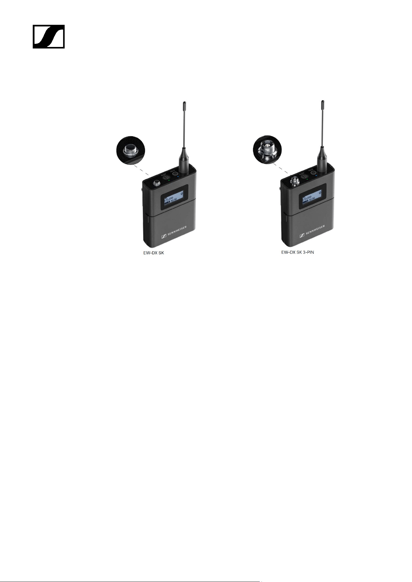
EW-DX SK | EW-DX SK 3-PIN bodypack transmitter
EW-DX SK bodypack transmitter
The EW-DX SK bodypack transmitter is available in the following versions:
EW-DX SK (Q1–9) | 470.2 – 550 MHz | Art. no. 509384
EW-DX SK (R1–9) | 520 – 607.8 MHz | Art. no. 509385
EW-DX SK (S1–10) | 606.2 – 693.8 MHz | Art. no. 509385
EW-DX SK (S2–10) | 614.2 – 693.8 MHz | Art. no. 509389
EW-DX SK (S4–10) | 630 – 693.8 MHz | Art. no. 509390
EW-DX SK (U1/5) | 823.2 – 831.8 MHz & 863.2 – 864.8 MHz | Art. no. 509391
EW-DX SK (V3–4) | 925.2 – 937.3 MHz | Art. no. 509393
EW-DX SK (V5–7) | 941.7 – 951.8 MHz & 953.05 – 956.05 MHz & 956.65 – 959.65 MHz | Art.
no. 509394
EW-DX SK (Y1–3) | 1785.2 – 1799.8 MHz | Art. no. 509397
EW-DX SK 3-PIN bodypack transmitter
The EW-DX SK 3-PIN bodypack transmitter is available in the following versions:
EW-DX SK 3-PIN (Q1–9) | 470.2 – 550 MHz | Art. no. 509398
EW-DX SK 3-PIN (R1–9) | 520 – 607.8 MHz | Art. no. 509399
38

| 2 - Product information
EW-DX SK 3-PIN (S1–10) | 606.2 – 693.8 MHz | Art. no. 509499
EW-DX SK 3-PIN (S2–10) | 614.2 – 693.8 MHz | Art. no. 509403
EW-DX SK 3-PIN (S4–10) | 630 – 693.8 MHz | Art. no. 509404
EW-DX SK 3-PIN (U1/5) | 823.2 – 831.8 MHz & 863.2 – 864.8 MHz | Art. no. 509405
EW-DX SK 3-PIN (V3–4) | 925.2 – 937.3 MHz | Art. no. 509407
EW-DX SK 3-PIN (V5–7) | 941.7 – 951.8 MHz & 953.05 – 956.05 MHz & 956.65 – 959.65 MHz
| Art. no. 509408
EW-DX SK 3-PIN (Y1–3) | 1785.2 – 1799.8 MHz | Art. no. 509411
You can find more detailed information about the EW-DX SK and EW-DX SK 3-
PIN in the following sections:
• Startup and operation: EW-DX SK | EW-DX SK 3-PIN bodypack
transmitter
• Specifications: EW-DX SK | EW-DX SK 3-PIN bodypack transmitter
• Compatible microphones: Connecting a microphone to the bodypack
transmitter
39
| 2 - Product information
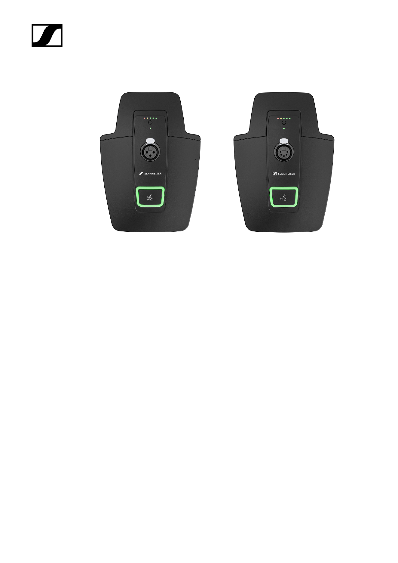
Table stand EW-DX TS 3-pin | EW-DX TS 5-pin
Table stand EW-DX TS 3-pin
The EW-DX TS 3-pin table stand is available in the following versions:
EW-DX TS 3-pin (Q1-9) | 470.2 – 550 MHz | Art. no. 509440
EW-DX TS 3-pin (R1-9) | 520 – 607.8 MHz | Art. no. 509441
EW-DX TS 3-pin (S1-10) | 606.2 – 693.8 MHz | Art. no. 509442
EW-DX TS 3-pin (S2-10) | 614.2 – 693.8 MHz | Art. no. 509445
EW-DX TS 3-pin (S4-10) | 630 – 693.8 MHz | Art. no. 509446
EW-DX TS 3-pin (U1/5) | 823.2 – 831.8 MHz & 863.2 – 864.8 MHz | Art. no. 509447
EW-DX TS 3-pin (V3-4) | 925.2 – 937.3 MHz | Art. no. 509449
EW-DX TS 3-pin (V5-7) | 941.7 – 951.8 MHz & 953.05 – 956.05 MHz & 956.65 – 959.65 MHz |
Art. no. 509450
EW-DX TS 3-pin (Y1-3) | 1785.2 – 1799.8 MHz | Art. no. 509453
Table stand EW-DX TS 5-pin
The EW-DX TS 5-pin table stand is available in the following versions:
EW-DX TS 5-pin (Q1-9) | 470.2 – 550 MHz | Art. no. 700191
EW-DX TS 5-pin (R1-9) | 520 – 607.8 MHz | Art. no. 700192
EW-DX TS 5-pin (S1-10) | 606.2 – 693.8 MHz | Art. no. 700193
40

| 2 - Product information
EW-DX TS 5-pin (S2-10) | 614.2 – 693.8 MHz | Art. no. 700195
EW-DX TS 5-pin (S4-10) | 630 – 693.8 MHz | Art. no. 700196
EW-DX TS 5-pin (U1/5) | 823.2 – 831.8 MHz & 863.2 – 864.8 MHz | Art. no. 700197
EW-DX TS 5-pin (V3-4) | 925.2 – 937.3 MHz | Art. no. 700199
EW-DX TS 5-pin (V5-7) | 941.7 – 951.8 MHz & 953.05 – 956.05 MHz & 956.65 – 959.65 MHz |
Art. no. 700200
EW-DX TS 5-pin (Y1-3) | 1785.2 – 1799.8 MHz | Art. no. 700203
You can find more detailed information about the EW-DX TS in the following
sections:
• Startup and operation: Table stand EW-DX TS 3-pin | EW-DX TS 5-pin
• Specifications: Table stand EW-DX TS 3-pin | EW-DX TS 5-pin
• Compatible microphones: Connecting a gooseneck microphone
41
| 2 - Product information
Sets available for the EW-DX series
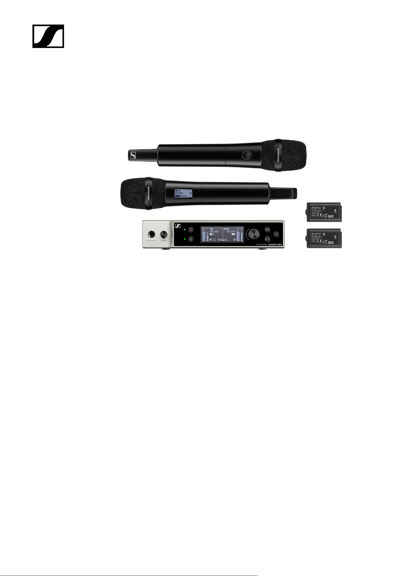
EW-DX 835-S SET | Handheld Set
The set consists of the following components:
• EW-DX EM 2 rack receiver
• 2x EW-DX SKM-S handheld transmitters
• 2x MMD 835 microphone module
• 2x BA 70 rechargeable batteries
The set is available in the following versions:
EW-DX 835-S SET (Q1–9) | 470.2 – 550 MHz | Art. no. 509300
EW-DX 835-S SET (R1–9) | 520 – 607.8 MHz | Art. no. 509301
EW-DX 835-S SET (S1–10) | 606.2 – 693.8 MHz | Art. no. 509302
EW-DX 835-S SET (S2–10) | 614.2 – 693.8 MHz | Art. no. 509305
EW-DX 835-S SET (S4–10) | 630 – 693.8 MHz | Art. no. 509306
EW-DX 835-S SET (U1/5) | 823.2 – 831.8 MHz & 863.2 – 864.8 MHz | Art. no. 509307
EW-DX 835-S SET (V3–4) | 925.2 – 937.3 MHz | Art. no. 509309
EW-DX 835-S SET (V5–7) | 941.7 – 951.8 MHz & 953.05 – 956.05 MHz & 956.65 – 959.65
MHz | Art. no. 509310
EW-DX 835-S SET (Y1–3) | 1785.2 – 1799.8 MHz | Art. no. 509313
42

| 2 - Product information
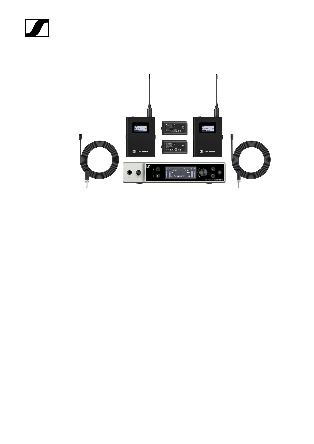
EW-DX MKE 2 SET | Lavalier Set
The set consists of the following components:
• EW-DX EM rack receiver
• 2x EW-DX SK bodypack transmitter
• 2x MKE 2 lavalier microphone
• 2x BA 70 rechargeable batteries
The set is available in the following versions:
EW-DX MKE 2 SET (Q1–9) | 470.2 – 550 MHz | Art. no. 509314
EW-DX MKE 2 SET (R1–9) | 520 – 607.8 MHz | Art. no. 509315
EW-DX MKE 2 SET (S1–10) | 606.2 – 693.8 MHz | Art. no. 509316
EW-DX MKE 2 SET (S2–10) | 614.2 – 693.8 MHz | Art. no. 509319
EW-DX MKE 2 SET (S4–10) | 630 – 693.8 MHz | Art. no. 509320
EW-DX MKE 2 SET (U1/5) | 823.2 – 831.8 MHz & 863.2 – 864.8 MHz | Art. no. 509321
EW-DX MKE 2 SET (V3–4) | 925.2 – 937.3 MHz | Art. no. 509323
EW-DX MKE 2 SET (V5–7) | 941.7 – 951.8 MHz & 953.05 – 956.05 MHz & 956.65 – 959.65
MHz | Art. no. 509324
EW-DX MKE 2 SET (Y1–3) | 1785.2 – 1799.8 MHz | Art. no. 509327
44

| 2 - Product information
EW-DX MKE 2-835-S SET | Combo Set
The set consists of the following components:
• EW-DX EM rack receiver
• 1x EW-DX SK bodypack transmitter
• 1x MKE 2 lavalier microphone
• 1x EW-DX SKM-S handheld transmitter
• 1x MMD 835 microphone module
• 2x BA 70 rechargeable batteries
The set is available in the following versions:
EW-DX MKE 2-835-S SET (Q1–9) | 470.2 – 550 MHz | Art. no. 509328
EW-DX MKE 2-835-S SET (R1–9) | 520 – 607.8 MHz | Art. no. 509329
EW-DX MKE 2-835-S SET (S1–10) | 606.2 – 693.8 MHz | Art. no. 509330
EW-DX MKE 2-835-S SET (S2–10) | 614.2 – 693.8 MHz | Art. no. 509333
EW-DX MKE 2-835-S SET (S4–10) | 630 – 693.8 MHz | Art. no. 509334
EW-DX MKE 2-835-S SET (U1/5) | 823.2 – 831.8 MHz & 863.2 – 864.8 MHz | Art. no. 509335
EW-DX MKE 2-835-S SET (V3–4) | 925.2 – 937.3 MHz | Art. no. 509337
46

| 2 - Product information
EW-DX MKE 2-835-S SET (V5–7) | 941.7 – 951.8 MHz & 953.05 – 956.05 MHz & 956.65 –
959.65 MHz | Art. no. 509338
EW-DX MKE 2-835-S SET (Y1–3) | 1785.2 – 1799.8 MHz | Art. no. 509341
You can find more detailed information about the set in the following sections:
• Startup and operation: Instruction manual
• Specifications: Specifications
47
| 2 - Product information
EW-DX SK-SKM-S BASE SET | Base Set
The set consists of the following components:
• EW-DX EM rack receiver
• 1x EW-DX SK bodypack transmitter
• 1x EW-DX SKM-S handheld transmitter
• 2x BA 70 rechargeable batteries
The set is available in the following versions:
EW-DX SK-SKM-S BASE SET (Q1–9) | 470.2 – 550 MHz | Art. no. 509462
EW-DX SK-SKM-S BASE SET (R1–9) | 520 – 607.8 MHz | Art. no. 509463
EW-DX SK-SKM-S BASE SET (S1–10) | 606.2 – 693.8 MHz | Art. no. 509464
EW-DX SK-SKM-S BASE SET (S2–10) | 614.2 – 693.8 MHz | Art. no. 509467
EW-DX SK-SKM-S BASE SET (S4–10) | 630 – 693.8 MHz | Art. no. 509468
EW-DX SK-SKM-S BASE SET (U1/5) | 823.2 – 831.8 MHz & 863.2 – 864.8 MHz | Art. no.
509469
EW-DX SK-SKM-S BASE SET (V3–4) | 925.2 – 937.3 MHz | Art. no. 509471
EW-DX SK-SKM-S BASE SET (V5–7) | 941.7 – 951.8 MHz & 953.05 – 956.05 MHz & 956.65 –
959.65 MHz | Art. no. 509338
48

| 2 - Product information
Products of the EW-DP series
For information about the available accessories, see Accessories.
For information about the available sets, see Sets available for the EW-DP series.
For information about the frequency ranges, see Frequency ranges.
You can find technical specifications for the series and the individual products under
Specifications.
You can find information about starting up and operating the products under Instruction
manual.
50
| 2 - Product information
EW-DP EK portable receiver
The EW-DP EK portable receiver is available in the following versions:
EW-DP EK (Q1–6) | 470.2 – 526 MHz | Art. no. 700050
EW-DP EK (R1–6) | 520 – 576 MHz | Art. no. 700051
EW-DP EK (R4–9) | 552 – 607.8 MHz | Art. no. 700052
EW-DP EK (S1–7) | 606.2 – 662 MHz | Art. no. 700053
EW-DP EK (S4–7) | 630 – 662 MHz | Art. no. 700054
EW-DP EK (S7–10) | 662 – 693.8 MHz | Art. no. 700055
EW-DP EK (T1/7) | 694,5 - 702,7 MHz & 748,3 - 757,7 MHz | Art. no. 700475
EW-DP EK (T12) | 806,125 - 809,75 MHz | Art. no. 700476
EW-DP EK (T13-14) | 819,2 - 823 MHz | Art. no. 700477
EW-DP EK (U1/5) | 823.2 – 831.8 MHz & 863.2 – 864.8 MHz | Art. no. 700056
EW-DP EK (V3–4) | 925.2 – 937.3 MHz | Art. no. 700058
EW-DP EK (Y1–3) | 1785.2 – 1799.8 MHz | Art. no. 700059
You can find more detailed information about the EW-DP EK in the following
sections:
• Startup and operation: EW-DP EK portable receiver
• Specifications: EW-DP EK portable receiver
51
| 2 - Product information
EW-DP SKP plug-on transmitter
The EW-DP SKP plug-on transmitter is available in the following versions:
EW-DP SKP (Q1–6) | 470.2 – 526 MHz | Art. no. 700080
EW-DP SKP (R1–6) | 520 – 576 MHz | Art. no. 700081
EW-DP SKP (R4–9) | 552 – 607.8 MHz | Art. no. 700082
EW-DP SKP (S1–7) | 606.2 – 662 MHz | Art. no. 700083
EW-DP SKP (S4–7) | 630 – 662 MHz | Art. no. 700084
EW-DP SKP (S7–10) | 662 – 693.8 MHz | Art. no. 700085
EW-DP EK (T1/7) | 694,5 - 702,7 MHz & 748,3 - 757,7 MHz | Art. no. 700478
EW-DP EK (T12) | 806,125 - 809,75 MHz | Art. no. 700479
EW-DP EK (T13-14) | 819,2 - 823 MHz | Art. no. 700480
EW-DP SKP (U1/5) | 823.2 – 831.8 MHz & 863.2 – 864.8 MHz | Art. no. 700086
EW-DP SKP (V3–4) | 925.2 – 937.3 MHz | Art. no. 700088
EW-DP SKP (Y1–3) | 1785.2 – 1799.8 MHz | Art. no. 700089
You can find more detailed information about the EW-DP SKP in the following
sections:
• Startup and operation: EW-DP EK portable receiver
• Specifications: EW-DP SKP plug-on transmitter
52
| 2 - Product information
Sets available for the EW-DP series
EW-DP ME-2 | Lavalier Set
The set consists of the following components:
• EW-DP EK portable receiver
• EW-D SK bodypack transmitter
• ME 2 lavalier microphone
The set is available in the following versions:
EW-DP ME-2 SET (Q1–6) | 470.2 – 526 MHz | Art. no. 508710
EW-DP ME-2 SET (R1–6) | 520 – 576 MHz | Art. no. 508711
EW-DP ME-2 SET (R4–9) | 552 – 607.8 MHz | Art. no. 508712
EW-DP ME-2 SET (S1–7) | 606.2 – 662 MHz | Art. no. 508713
EW-DP ME-2 SET (S4–7) | 630 – 662 MHz | Art. no. 508714
EW-DP ME-2 SET (S7–10) | 662 – 693.8 MHz | Art. no. 508715
EW-DP ME-2 SET (T1/7) | 694,5 - 702,7 MHz & 748,3 - 757,7 MHz | Art. no. 700463
EW-DP ME-2 SET (T12) | 806,125 - 809,75 MHz | Art. no. 700464
EW-DP ME-2 SET (T13-14) | 819,2 - 823 MHz | Art. no. 700465
53

| 2 - Product information
EW-DP ME-2 SET (U1/5) | 823.2 – 831.8 MHz & 863.2 – 864.8 MHz | Art. no. 508716
EW-DP ME-2 SET (V3–4) | 925.2 – 937.3 MHz | Art. no. 508718
EW-DP ME-2 SET (Y1–3) | 1785.2 – 1799.8 MHz | Art. no. 508719
You can find more detailed information about the set in the following sections:
• Startup and operation: Instruction manual
• Specifications: Specifications
54
| 2 - Product information
EW-DP ME-4 | Lavalier Set
The set consists of the following components:
• EW-DP EK portable receiver
• EW-D SK bodypack transmitter
• ME 4 lavalier microphone
The set is available in the following versions:
EW-DP ME-4 SET (Q1–6) | 470.2 – 526 MHz | Art. no. 508720
EW-DP ME-4 SET (R1–6) | 520 – 576 MHz | Art. no. 508721
EW-DP ME-4 SET (R4–9) | 552 – 607.8 MHz | Art. no. 508722
EW-DP ME-4 SET (S1–7) | 606.2 – 662 MHz | Art. no. 508723
EW-DP ME-4 SET (S4–7) | 630 – 662 MHz | Art. no. 508724
EW-DP ME-4 SET (S7–10) | 662 – 693.8 MHz | Art. no. 508725
EW-DP ME-4 SET (T1/7) | 694,5 - 702,7 MHz & 748,3 - 757,7 MHz | Art. no. 700466
EW-DP ME-4 SET (T12) | 806,125 - 809,75 MHz | Art. no. 700467
EW-DP ME-4 SET (T13-14) | 819,2 - 823 MHz | Art. no. 700468
EW-DP ME-4 SET (U1/5) | 823.2 – 831.8 MHz & 863.2 – 864.8 MHz | Art. no. 508726
EW-DP ME-4 SET (V3–4) | 925.2 – 937.3 MHz | Art. no. 508728
55

| 2 - Product information
EW-DP 835 | Handheld Set
The set consists of the following components:
• EW-DP EK portable receiver
• EW-D SKM-S handheld transmitter
• MMD 835 microphone module
The set is available in the following versions:
EW-DP 835 SET (Q1–6) | 470.2 – 526 MHz | Art. no. 508730
EW-DP 835 SET (R1–6) | 520 – 576 MHz | Art. no. 508731
EW-DP 835 SET (R4–9) | 552 – 607.8 MHz | Art. no. 508732
EW-DP 835 SET (S1–7) | 606.2 – 662 MHz | Art. no. 508733
EW-DP 835 SET (S4–7) | 630 – 662 MHz | Art. no. 508734
EW-DP 835 SET (S7–10) | 662 – 693.8 MHz | Art. no. 508735
EW-DP 835 SET (T1/7) | 694,5 - 702,7 MHz & 748,3 - 757,7 MHz | Art. no. 700469
EW-DP 835 SET (T12) | 806,125 - 809,75 MHz | Art. no. 700470
57

| 2 - Product information
EW-DP 835 SET (T13-14) | 819,2 - 823 MHz | Art. no. 700471
EW-DP 835 SET (U1/5) | 823.2 – 831.8 MHz & 863.2 – 864.8 MHz | Art. no. 508736
EW-DP 835 SET (V3–4) | 925.2 – 937.3 MHz | Art. no. 508738
EW-DP 835 SET (Y1–3) | 1785.2 – 1799.8 MHz | Art. no. 508739
You can find more detailed information about the set in the following sections:
• Startup and operation: Instruction manual
• Specifications: Specifications
58
| 2 - Product information
EW-DP ENG | Lavalier Set
The set consists of the following components:
• EW-DP EK portable receiver
• EW-D SK bodypack transmitter
• EW-DP SKP plug-on transmitter
• ME 2 lavalier microphone
The set is available in the following versions:
EW-DP ENG SET (Q1-6) | 470.2 - 526 MHz | Art. no. 700040
EW-DP ENG SET (R1-6) | 520 - 576 MHz | Art. no. 700041
EW-DP ENG SET (R4-9) | 552 - 607.8 MHz | Art. no. 700042
EW-DP ENG SET (S1-7) | 606.2 - 662 MHz | Art. no. 700043
EW-DP ENG SET (S4-7) | 630 - 662 MHz | Art. no. 700044
EW-DP ENG SET (S7-10) | 662 - 693.8 MHz | Art. no. 700045
EW-DP ENG SET (T1/7) | 694,5 - 702,7 MHz & 748,3 - 757,7 MHz | Art. no. 700472
EW-DP ENG SET (T12) | 806,125 - 809,75 MHz | Art. no. 700473
EW-DP ENG SET (T13-14) | 819,2 - 823 MHz | Art. no. 700474
EW-DP ENG SET (U1/5) | 823.2 - 831.8 MHz & 863.2 - 864.8 MHz | Art. no. 700046
EW-DP ENG SET (V3-4) | 925.2 - 937.3 MHz | Art. no. 700048
EW-DP ENG SET (Y1-3) | 1785.2 - 1799.8 MHz | Art. no. 700049
59

| 2 - Product information
Smart Assist app
You can operate your products easily and intuitively using the Smart Assist app for iOS and
Android.
You can make all device settings in the app and access other functions that are not available
on the devices themselves.
The app offers you the following benefits:
• Use all products easily and intuitively
• Update the firmware of all devices
• Easily configure multi-channel systems with automatic frequency setup
• Assign names and color labels to wireless links
• Get tips and support
61
| 2 - Product information
Accessories
BA 70 rechargeable battery and L 70 USB charger
BA 70 | Rechargeable battery | Art. no. 508860
L 70 USB | Charger | Art. no. 508861
EW-D CHARGING SET | L 70 USB charger with two BA 70 rechargeable batteries | Art. no.
508862
You can find more detailed information about the BA 70 rechargeable battery and
the L 70 USB charger in the following sections:
• Startup and operation: L 70 USB charger
• Specifications: L 70 USB charger | BA 70 rechargeable battery
62
| 2 - Product information
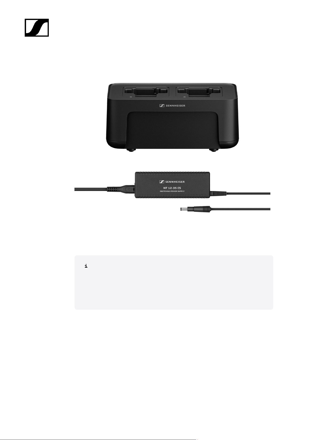
CHG 70N-C network-enabled charger
CHG 70N-C | Charger | Art. no. 700332
63
| 2 - Product information
CHG 70N-C + PSU KIT | CHG 70N-C charger with NT 12-35 CS power supply unit | Art. no.
700333
You can find more detailed information about the CHG 70N-C in the following
sections:
• Startup and operation: CHG 70N-C charger
• Specifications: CHG 70N-C charger | BA 70 rechargeable battery
64
| 2 - Product information
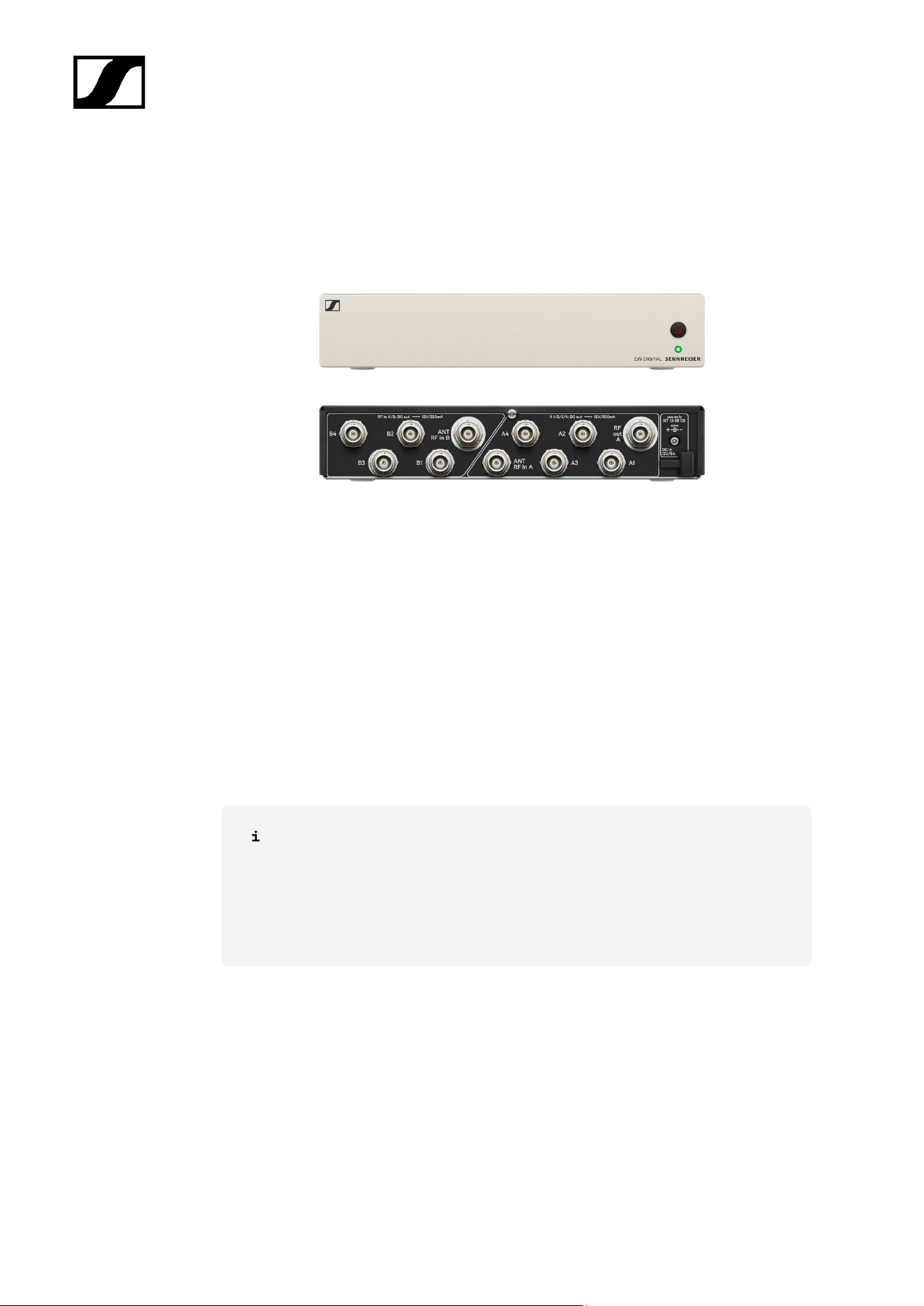
EW-D ASA antenna splitter
EW-D ASA active antenna splitter
Product versions:
EW-D ASA (Q-R-S) | 470 – 694 MHz | Art. no. 508879
EW-D ASA CN/ANZ (Q-R-S) | 470 – 694 MHz | Art. no. 508998
EW-D ASA (T-U-V-W) | 694 – 1075 MHz | Art. no. 508880
EW-D ASA (X-Y) | 1350 – 1805 MHz | Art. no. 508881
You can find more detailed information about the EW-D ASA in the following
sections:
• Startup and operation: EW-D ASA antenna splitter
• Specifications: EW-D ASA antenna splitter
65
| 2 - Product information
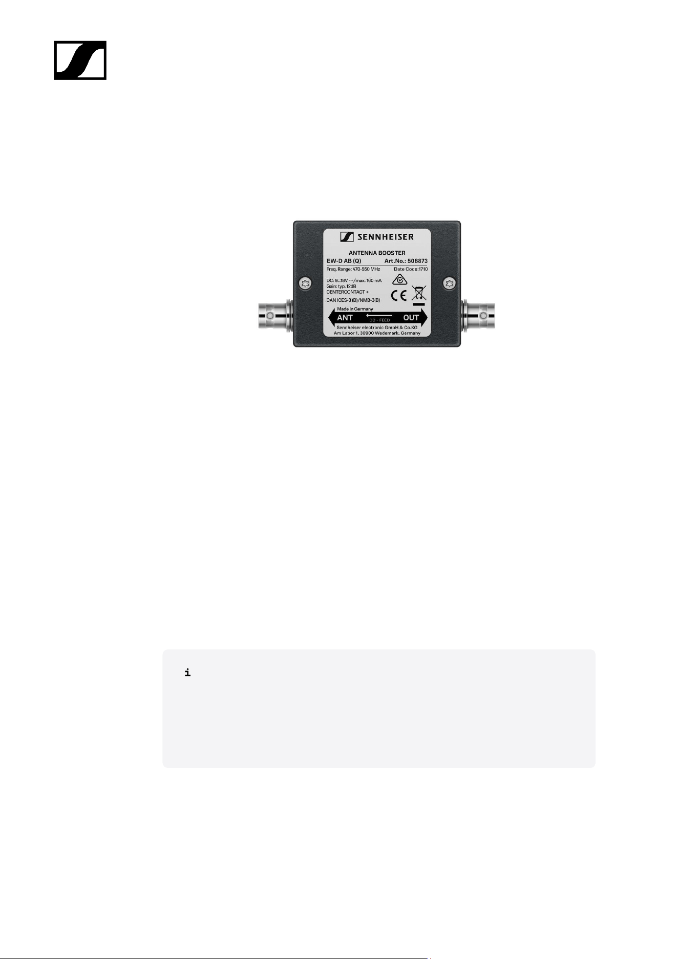
EW-D AB antenna booster
Product versions:
EW-D AB (Q) | 470 – 550 MHz | Art. no. 508873
EW-D AB (R) | 520 – 608 MHz | Art. no. 508874
EW-D AB (S) | 606 – 694 MHz | Art. no. 508875
EW-D AB (T) | 694 - 824 MHz | Art. no. 700462
EW-D AB (U) | 823 – 865 MHz | Art. no. 508876
EW-D AB (V) | 902 – 960 MHz | Art. no. 508877
EW-D AB (Y) | 1785 – 1805 MHz | Art. no. 508878
You can find more detailed information about the EW-D AB in the following
sections:
• Use: Information on antenna amplifiers and cable lengths
• Specifications: EW-D AB antenna booster
66

| 2 - Product information
Antennas
Rod antennas
Product versions:
Half Wave Dipole (Q) | 470 – 550 MHz | Art. no. 508868
Half Wave Dipole (R) | 520 – 608 MHz | Art. no. 508869
Half Wave Dipole (S) | 606 – 694 MHz | Art. no. 508870
Half Wave Dipole (T1-7) | 694,5 - 757,7 MHz | Art. no. 700461
Half Wave Dipole (T12-14) | 806,125 - 823 MHz | Art. no. 700504
Half Wave Dipole (U) | 823 – 865 MHz | Art. no. 508871
Half Wave Dipole (V) | 902 – 960 MHz | Art. no. 508966
Half Wave Dipole (Y) | 1785 – 1805 MHz | Art. no. 508872
67
| 2 - Product information
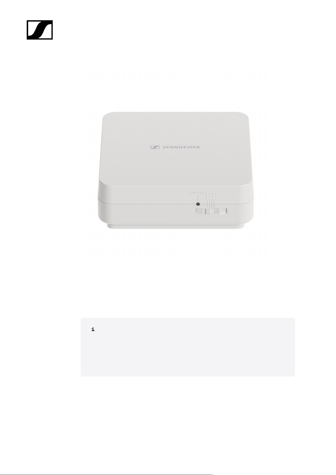
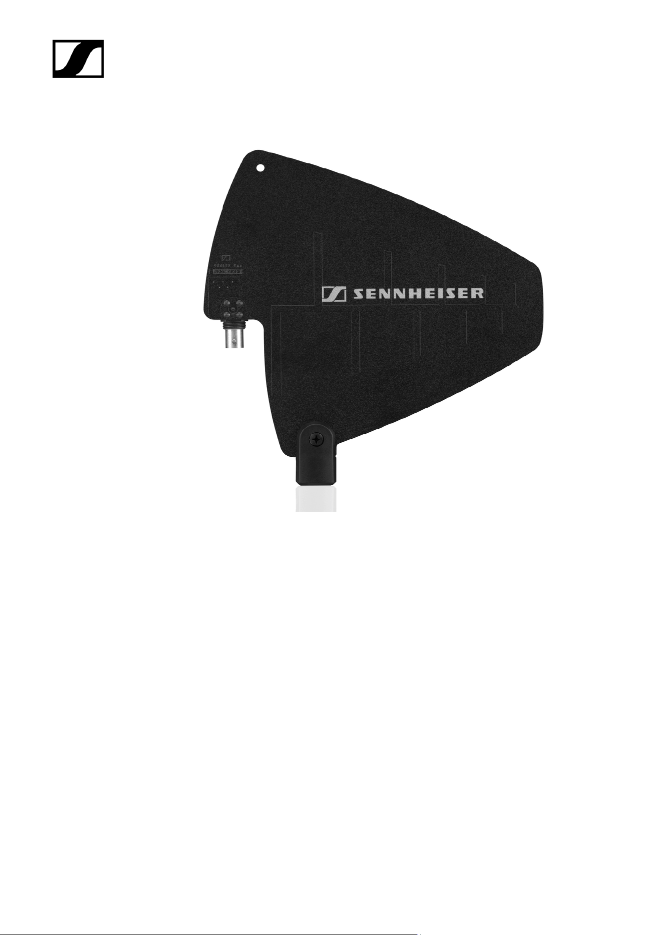
AWM active directional antenna
Product versions:
AWM UHF I | 470 – 694 MHz | Art. no. 508865
AWM UHF II | 823 – 1075 MHz | Art. no. 508866
AWM 1G8 | 1785 – 1805 MHz | Art. no. 508867
You can find more detailed information about the AWM antenna in the following
sections:
• Startup and operation: AWM active directional antenna
• Specifications: AWM active directional antenna
68
| 2 - Product information
AD 1800 passive directional antenna
AD 1800 | 1400 – 2400 MHz | Art. no. 504916
70
| 2 - Product information
Accessories for rack mounting
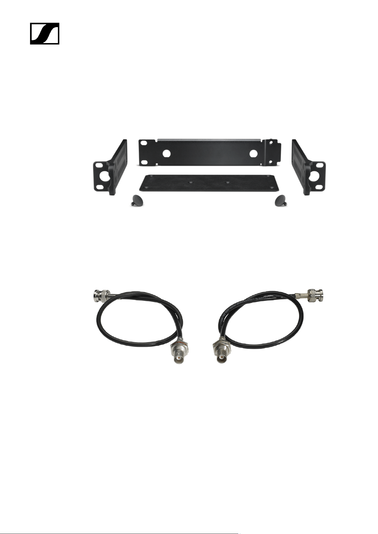
GA 3 rack mount kit
19" rack adapter for mounting the EW-D EM, EW-DX EM 2 or EW-D ASA in a 19" rack.
Art. no. 503167
AM 2 antenna front mount kit
Antenna front mount kit for installing antenna connections on the front of the rack when
using the EW-D EM, EW-DX EM 2 or EW-D ASA together with the GA 3 rack mount kit.
Art. no. 009912
Antenna Front Mount Kit
Antenna front mounting kit for 19" Sennheiser wireless rack units, including EW-DX EM 4
Dante.
Art. no. 700667
71

| 2 - Product information
72
| 2 - Product information
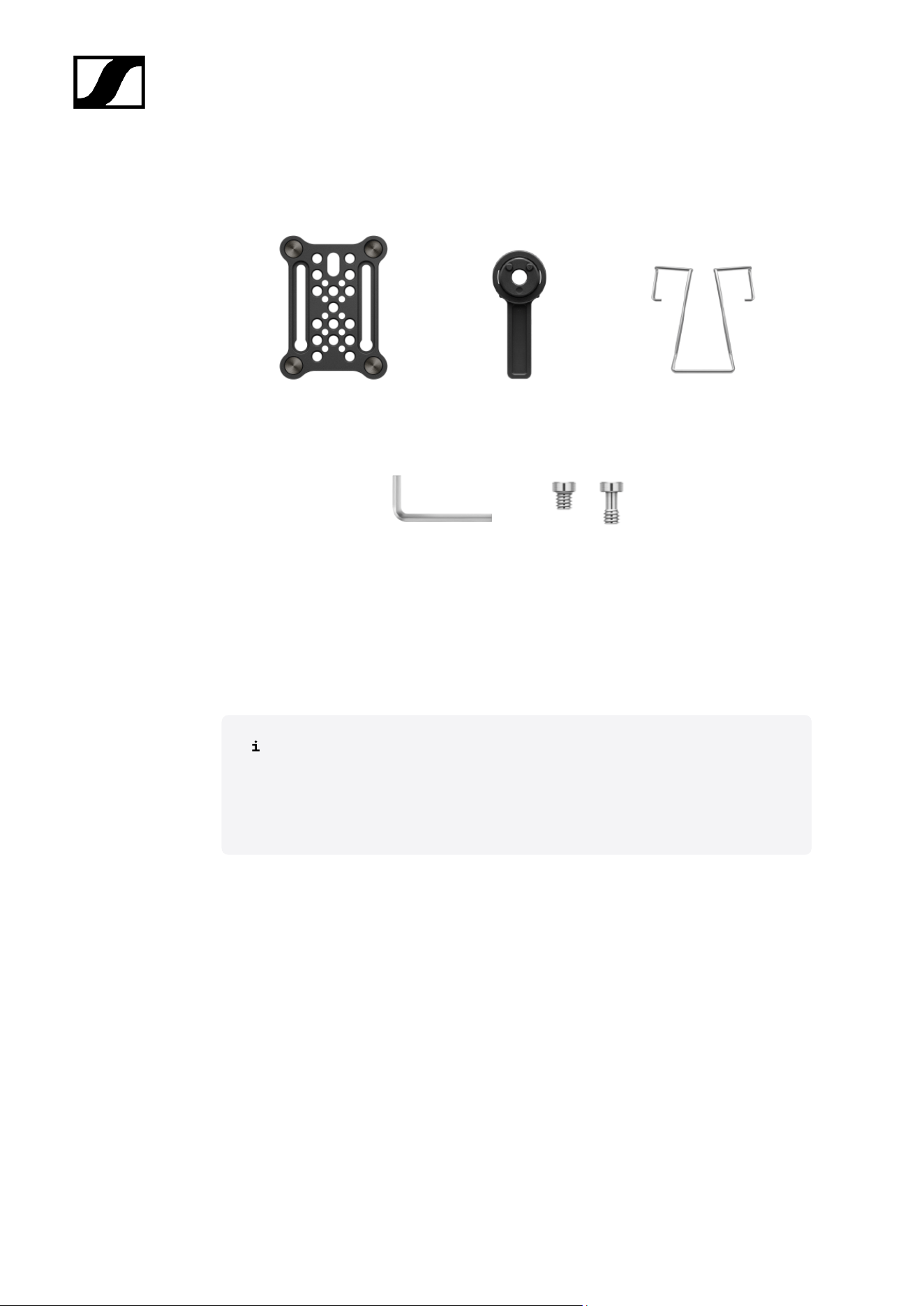
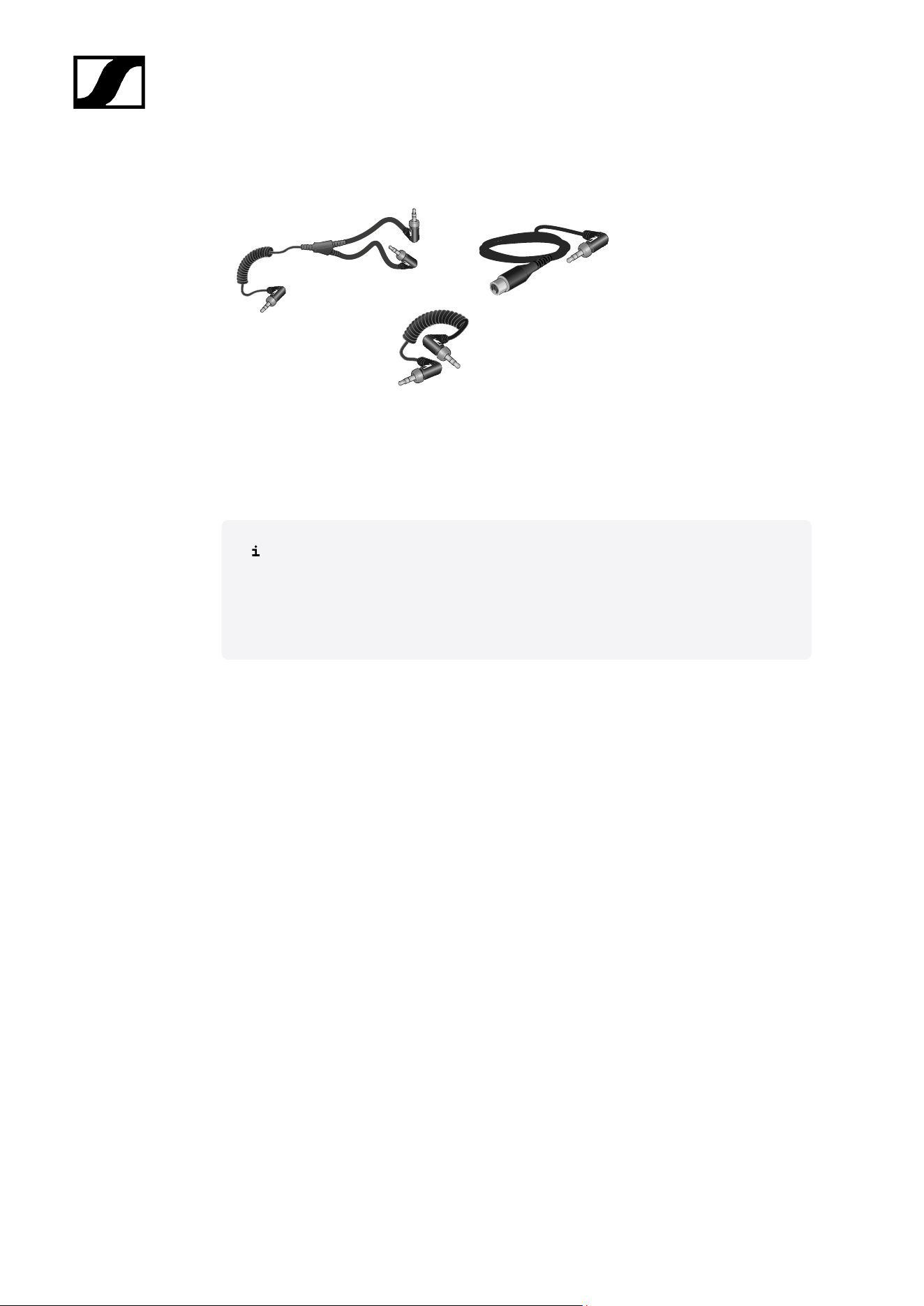
Cables for EW-DP EK
CL 35 | 3.5 mm jack cable | Art no. 586365
CL 35-Y | 3.5 mm Y-cable | Art. no. 700061
CL 35 XLR | 3.5 mm XLR cable | Art. no. 700062
3.5 mm jack cable, 3.5 mm Y-cable and 3.5 mm XLR cable for connecting one or
more EW-DP EK units to a camera.
• Startup and operation: EW-DP EK portable receiver
74
| 2 - Product information
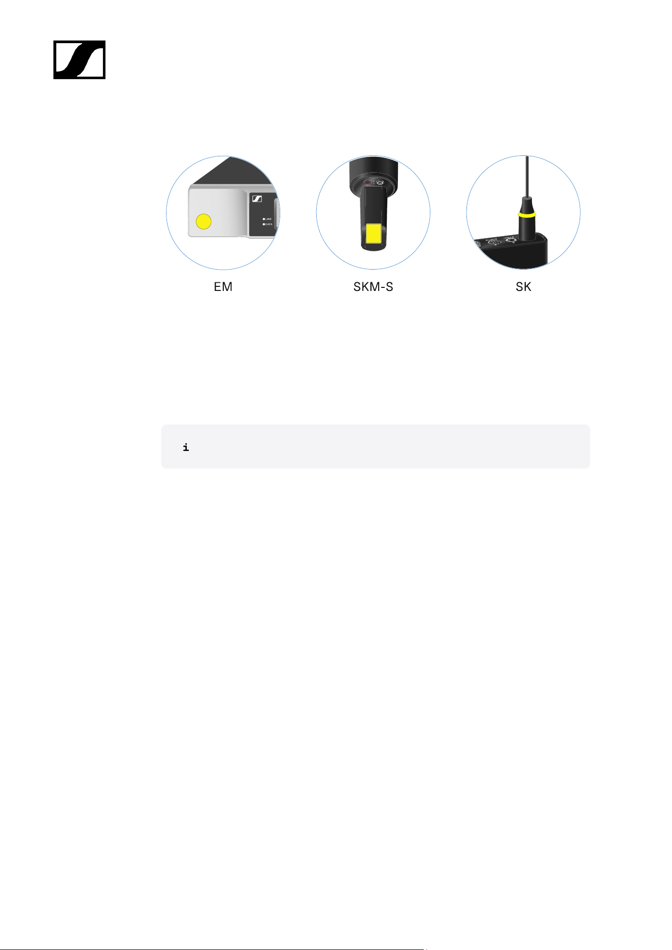
Color Coding Sets
EW-D COLOR CODING SET | For EM, SKM-S, SK | Art. no. 508989
EW-D SK COLOR CODING | For SK | Art. no. 508990
EW-D SKM COLOR CODING | For SKM-S | Art. no. 508991
EW-D EM COLOR CODING | For EM | Art. no. 508992
Using EW-D Color Coding Sets to label transmission paths
75
| 2 - Product information
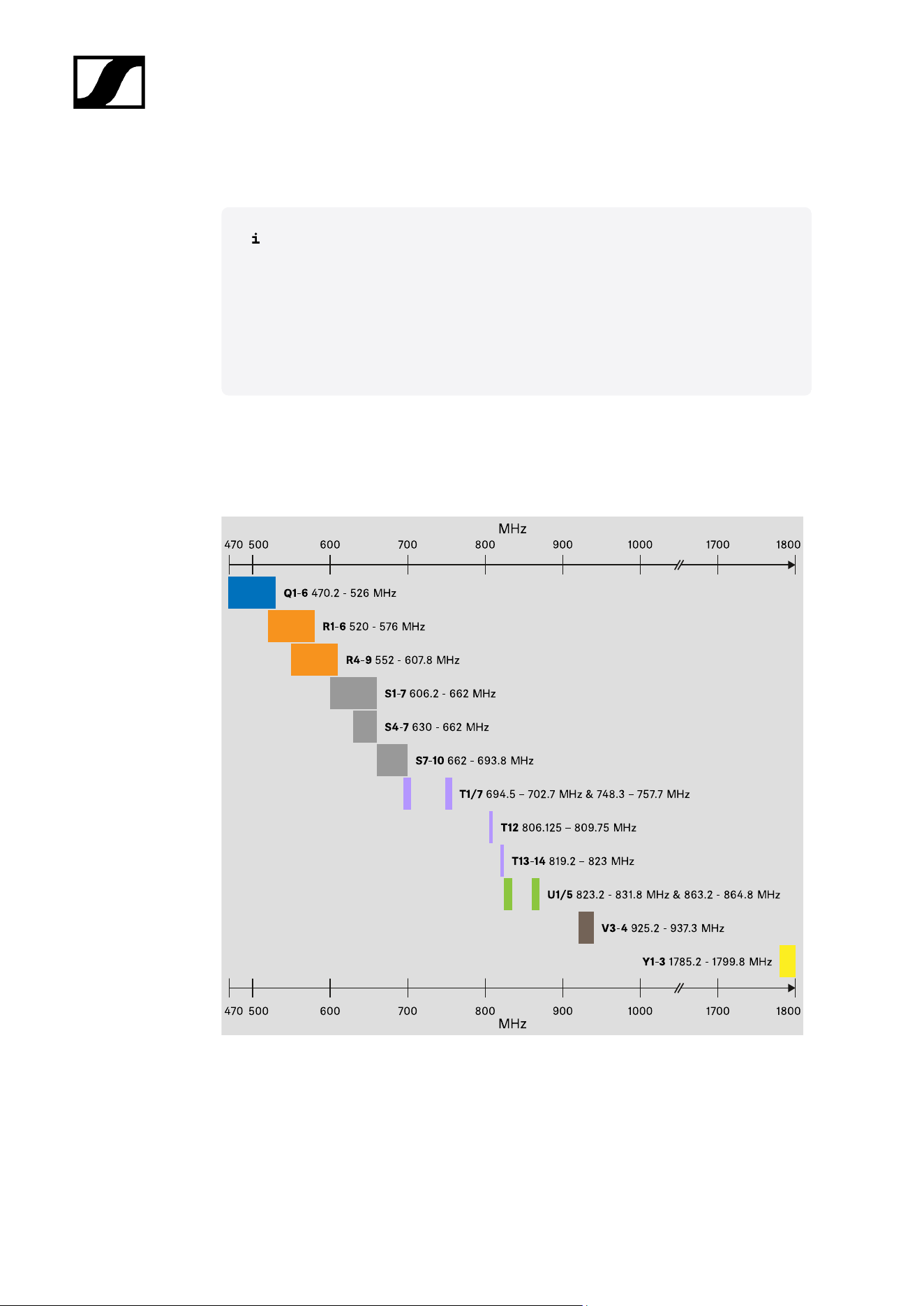
Frequency ranges
Frequency tables with the factory presets for all available frequency ranges can
be found in the download area of the Sennheiser website at:
sennheiser.com/download
• Enter EW-D, EW-DX or EW-DP in the search bar to show the frequency
tables.
EW-D | EW-DP
The products EW-D EM, EW-D SKM-S, EW-D SK, EW-DP EK and EW-DP SKP are available
in the following frequency ranges:
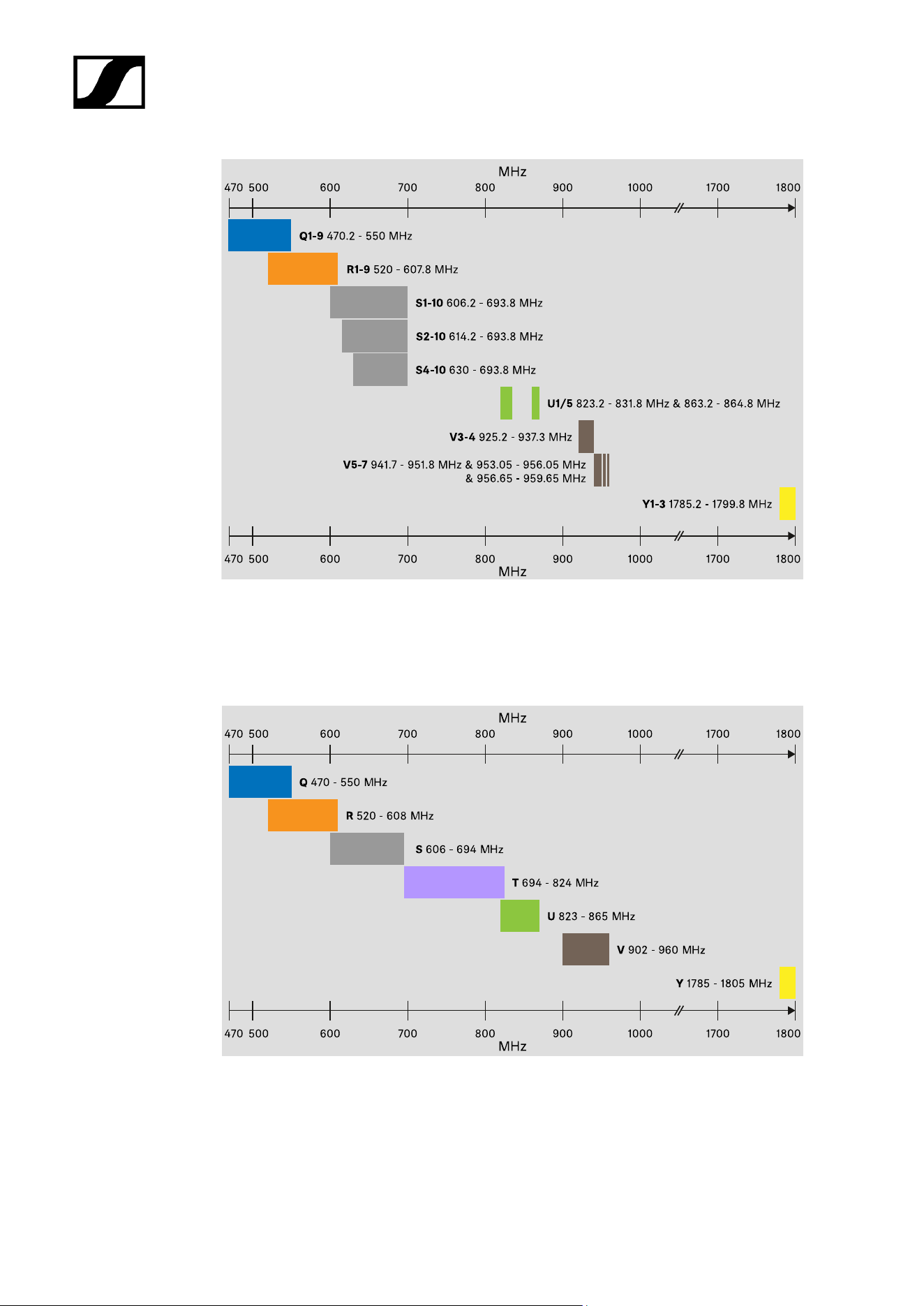
EW-DX
The products EW-DX EM 2, EW-DX EM 2 Dante, EW-DX EM 4 Dante, EW-DX SKM, EW-DX
SKM-S, EW-DX SK, EW-D SK 3-PIN, EW-DX TS 3-pin and EW-DX TS 5-pin are available in
the following frequency ranges:
76
| 2 - Product information
Accessories
The EW-D AB antenna booster and the Half Wave Dipole rod antennas are available in the
following frequency ranges:
The EW-D ASA antenna splitter is available in the following frequency ranges:
77

| 2 - Product information
470
500
600
70
800
900
1000
MHz
170
1800
Q-R-S 470 - 694 MHz
X-Y 1350 - 1805 MHz
T-U-V-W 694 - 1075 MHz
470
600
70
800
900
1000
MHz
170
1800
500
78
Evolution Wireless Digital
3. Instruction manual
Starting up and operating devices of the Evolution Wireless Digital series.
EW-D EM rack receiver
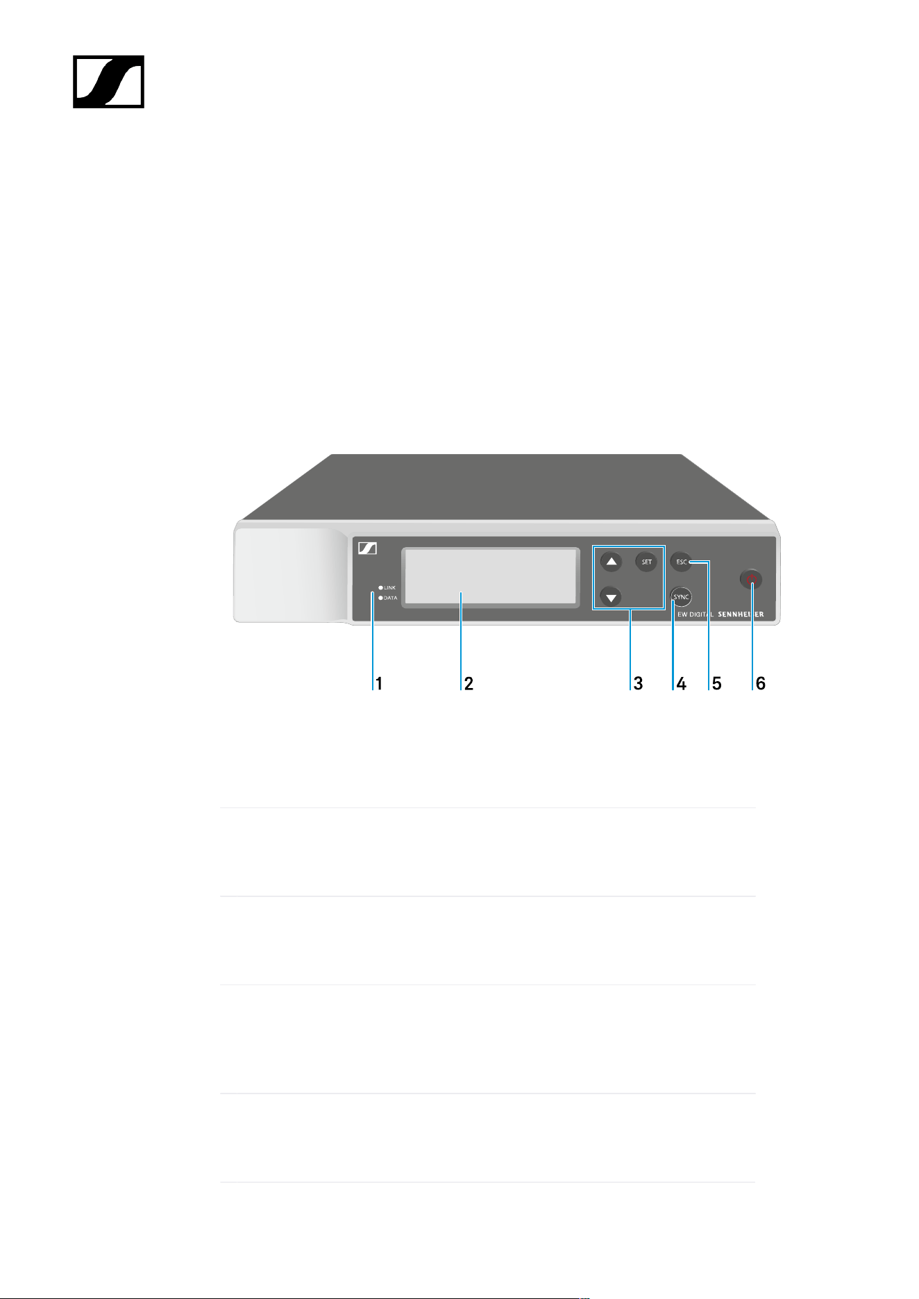
Product overview
Front
1 LINK and DATA LEDs to indicate connection status and Bluetooth status
• See Meaning of the LEDs
2 Display for status information and operating menu
• See Displays on the receiver’s display panel
3 UP/DOWN/SET menu buttons for navigating the operating menu
• See Buttons for navigating the menu
4 SYNC button
• See Establishing a radio link | Synchronizing the receiver and
transmitter
5 ESC button for canceling an action in the menu
• See Buttons for navigating the menu
79
| 3 - Instruction manual
6 ON/OFF button for switching the device on and off
• See Switching the receiver on and off
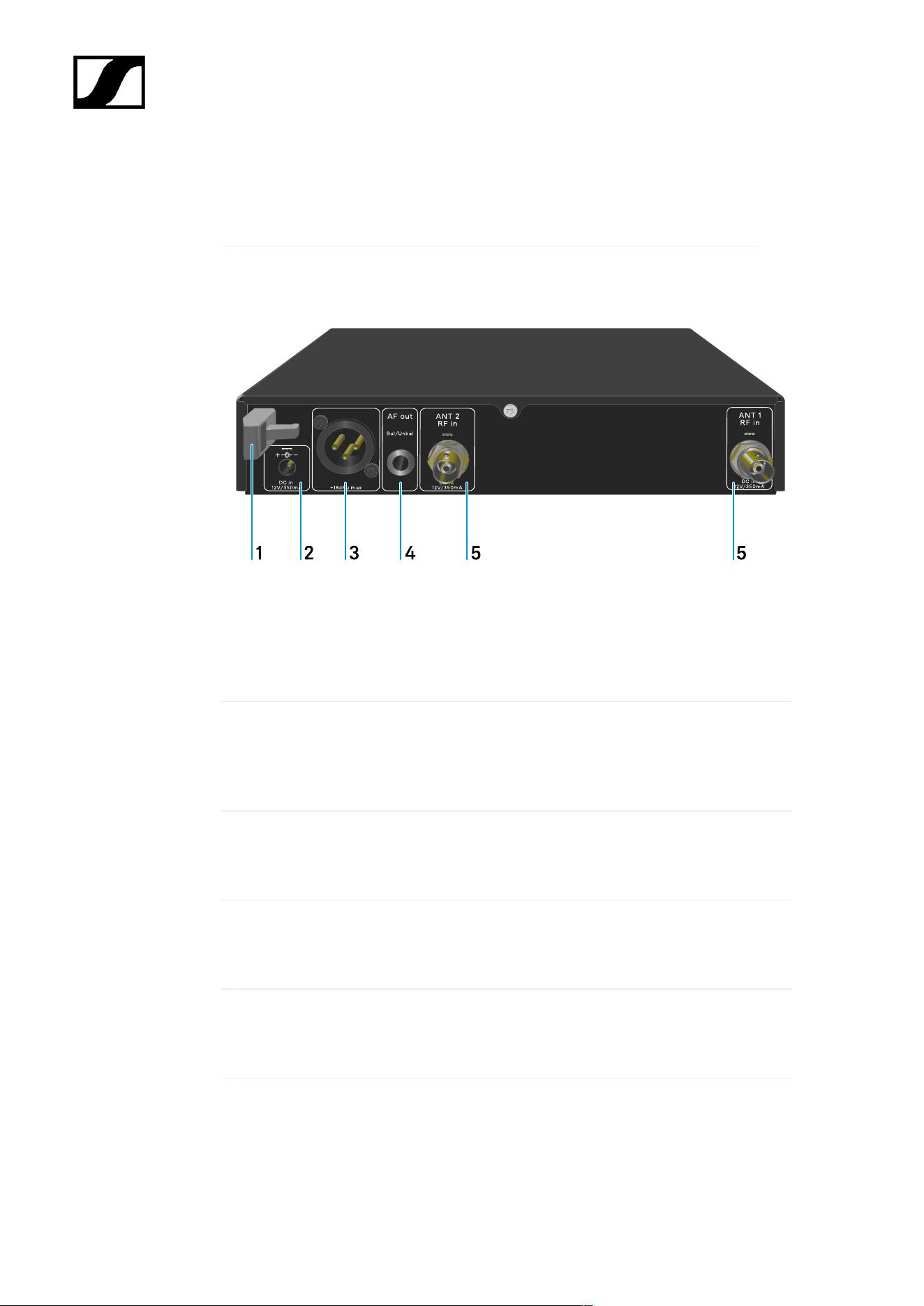
Back
1 Strain relief for the connection cable of the power supply unit
• See Connecting/disconnecting the receiver to/from the power supply
system
2 DC in connection socket for the power supply unit
• See Connecting/disconnecting the receiver to/from the power supply
system
3 XLR-3 socket AF out Bal for audio output
• See Outputting audio signals
4 6.3 mm jack socket AF out Unbal for audio output
• See Outputting audio signals
5 BNC sockets ANT 1 RF in and ANT 2 RF in for antenna inputs
• See Connecting antennas
80
| 3 - Instruction manual
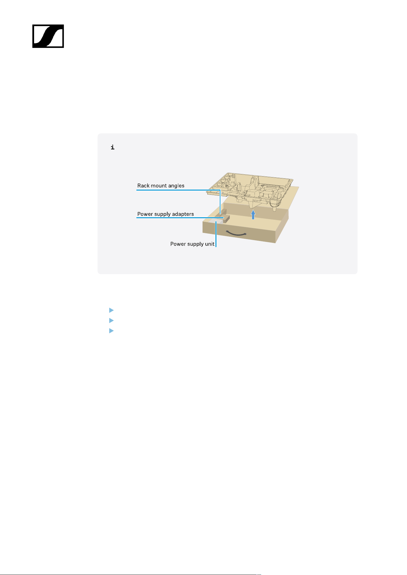
Connecting/disconnecting the receiver to/from the power supply
system
Use only the supplied power supply unit. It is designed for your receiver and ensures safe
operation.
You will find the power supply unit and the country adapters in the packaging
under the tray:
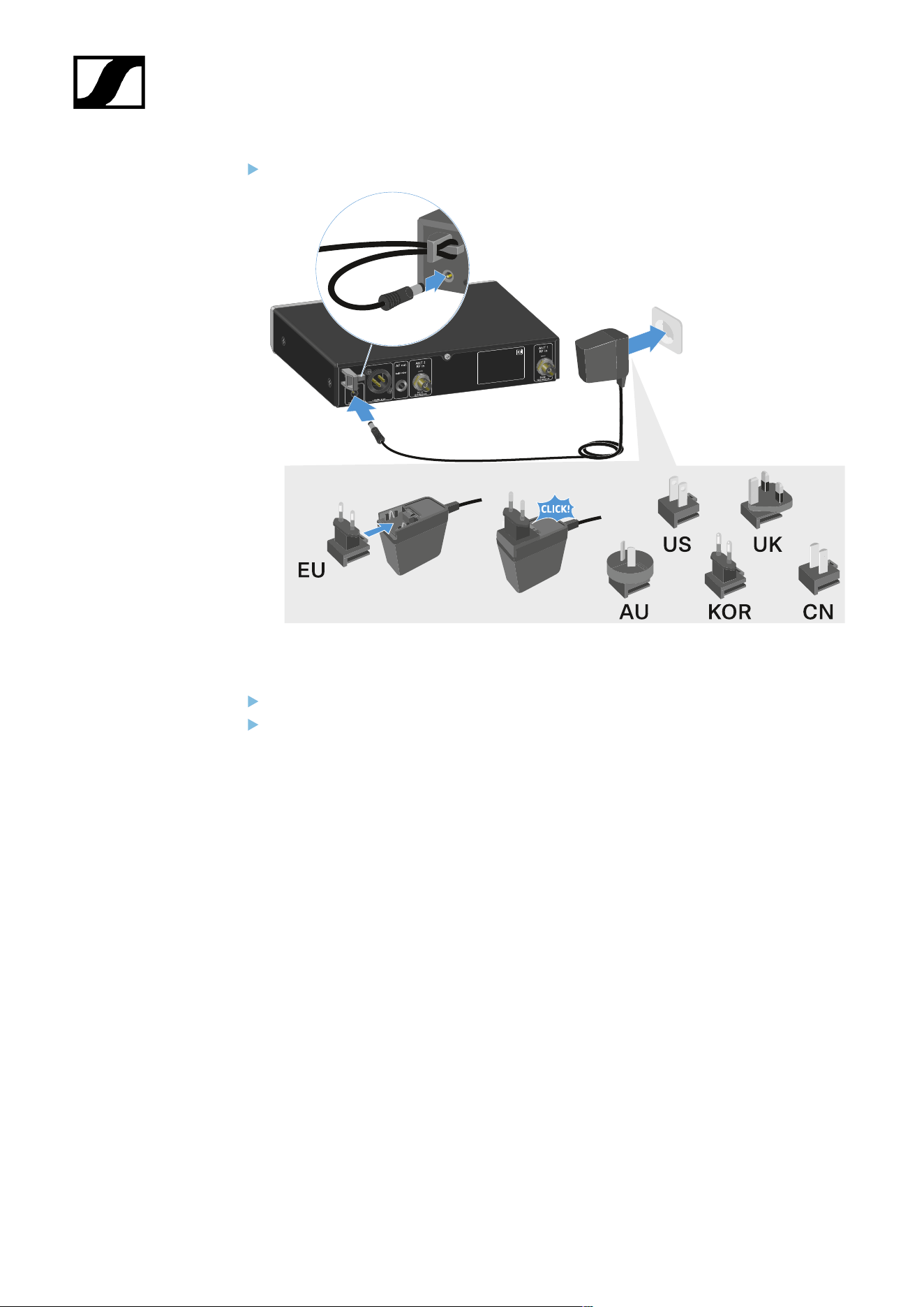
To connect the receiver to the power supply system:
Insert the plug of the power supply unit into the DC in socket on the receiver.
Pass the cable of the power supply unit through the strain relief.
Slide the supplied country adapter onto the power supply unit.
81
| 3 - Instruction manual
Plug the power supply unit into the wall socket.
To completely disconnect the receiver from the power supply system:
Unplug the power supply unit from the wall socket.
Unplug the power supply unit from the DC in socket on the receiver.
82
| 3 - Instruction manual
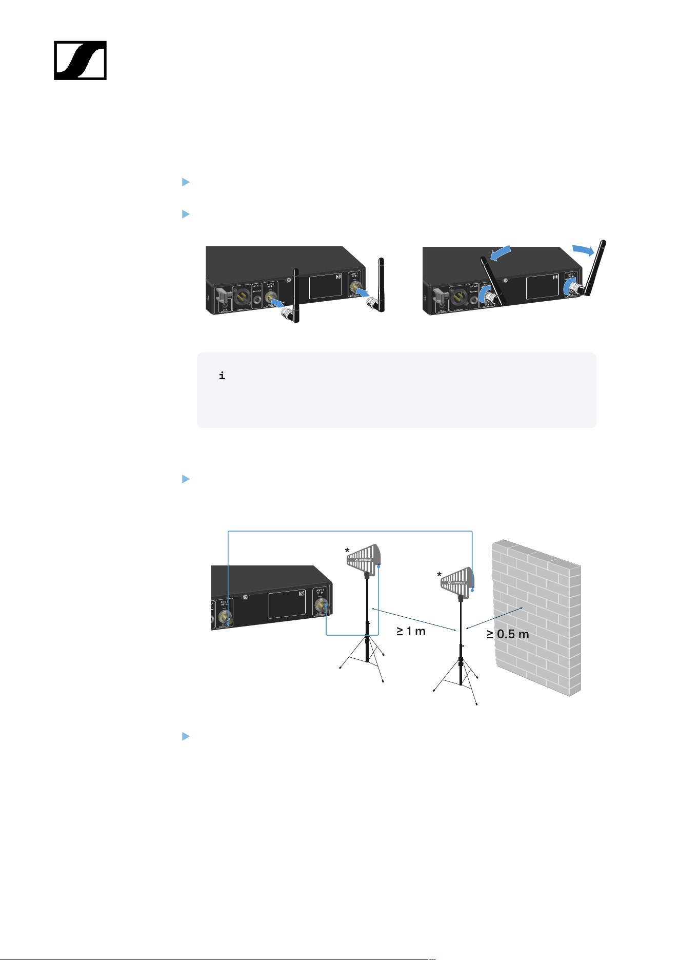
Connecting antennas
To connect the supplied rod antennas:
Connect the antennas to the two antenna inputs on the receiver as shown in the
figure.
Slightly angle the antennas to the left and right as shown in the figure.
If you are using more than one receiver, we recommend using remote
antennas and possibly the EW-D ASA antenna splitter (EW-D ASA
antenna splitter).
To connect remote antennas:
Connect the antennas to the two antenna inputs on the receiver as shown in the
figure.
Observe the specified minimum spacing.
83
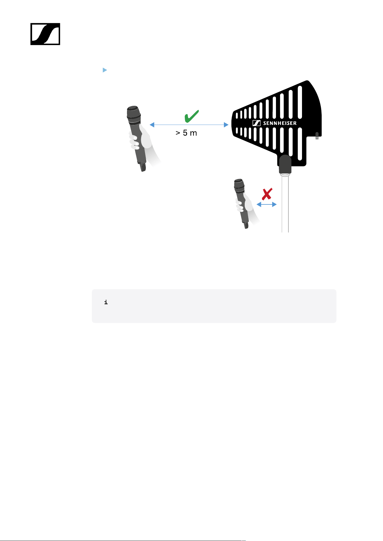
| 3 - Instruction manual
Observe the specified minimum spacing to the transmitters.
*Recommended antennas:
• ADP UHF | 470 – 1075 MHz
• AD 1800 | 1400 – 2400 MHz
If you are using more than one receiver, we recommend using remote antennas
and possibly the EW-D ASA antenna splitter (EW-D ASA antenna splitter).
84
| 3 - Instruction manual
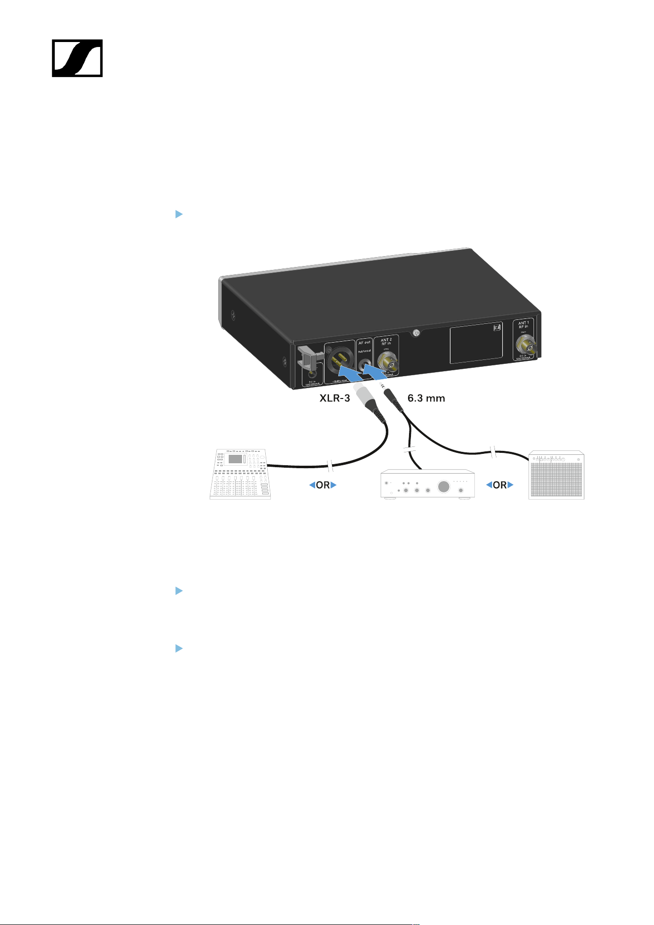
Outputting audio signals
The EW-D EM has a balanced XLR-3M output socket and an unbalanced 6.3 mm jack output
socket.
Always use only one of the two output sockets.
To connect an XLR cable:
Plug the XLR cable into the AF out Bal socket on the EW-D EM.
To connect a jack cable:
Plug the jack cable into the AF out Unbal socket on the EW-D EM.
85
| 3 - Instruction manual
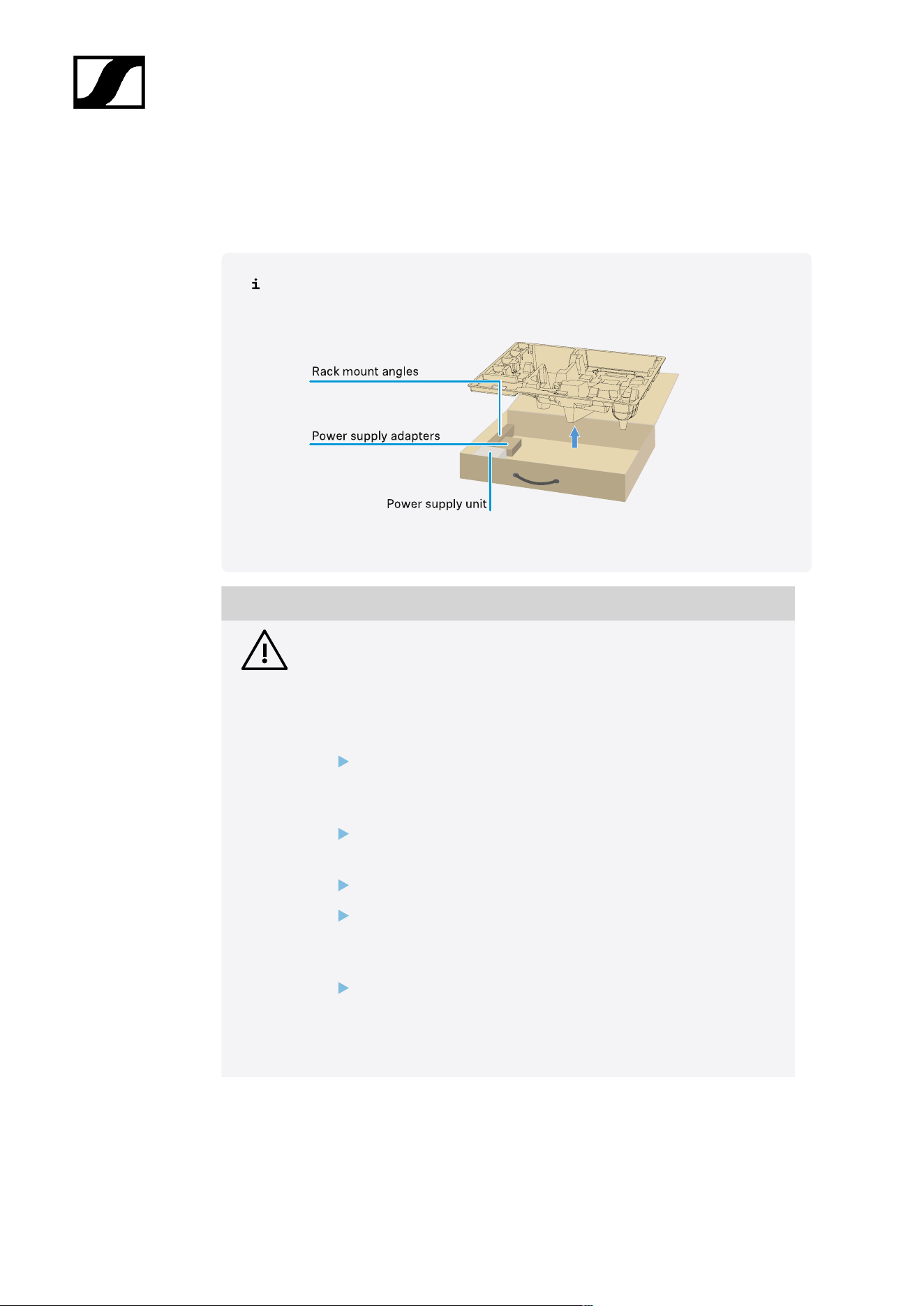
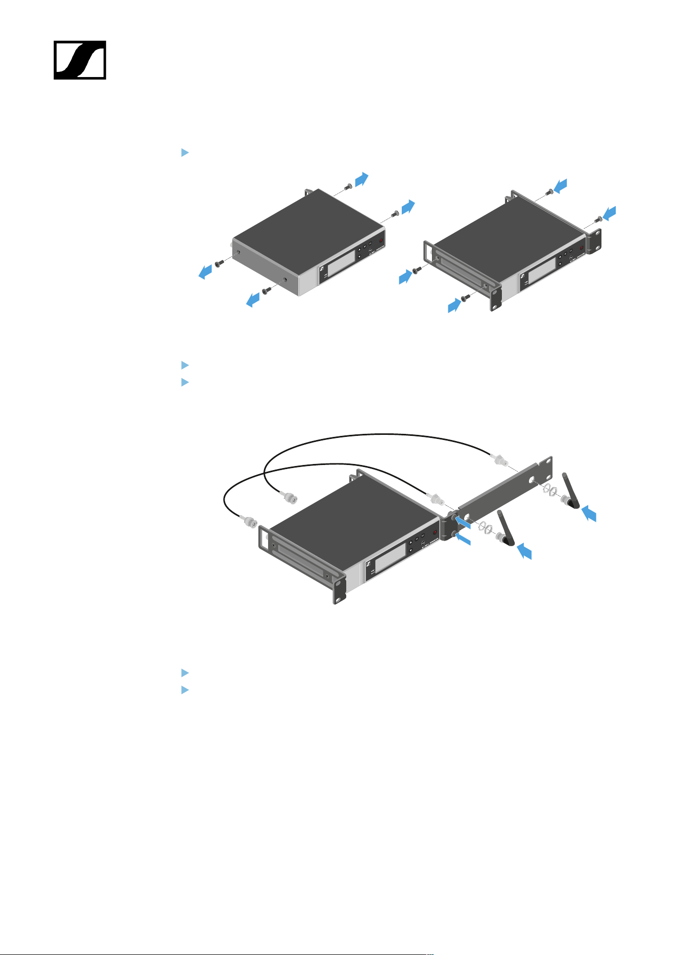
Installing receivers in a rack
Observe the following instructions when mounting the receiver in a rack.
The mounting brackets for installing the receiver in the rack can be found in the
packaging under the tray:
NOTICE
Rack mounting poses risks!
When installing the device in a closed 19" rack or multi-rack assembly,
please consider that, during operation, the ambient temperature, the
mechanical load and the electrical potentials will be different from those
of devices which are not mounted into a rack.
Make sure that the ambient temperature within the rack does
not exceed the permissible temperature limit stated in the
specifications. See (Specifications).
Ensure sufficient ventilation; if necessary, provide additional
ventilation.
Make sure that the mechanical load of the rack is even.
When connecting to the power supply system, observe the
information indicated on the type plate. Avoid overloading the
circuits. If necessary, provide overcurrent protection.
When mounting in a rack, please note that intrinsically harmless
leakage currents of the individual power supply units may
accumulate, thereby exceeding the permissible limit value. As a
remedy, ground the rack via an additional ground connection.
86
| 3 - Instruction manual
Mounting a single receiver in a rack:
Connect the mounting brackets to the sides of the receiver as shown.
Attach the front panel as shown.
If desired, attach the antennas to the front panel as shown. This requires the optional
AM 2 antenna front mount kit (see Accessories for rack mounting).
Mounting two receivers side by side in a rack
Place both receivers upside down and side by side on an even surface.
Tighten the jointing plate as shown.
87
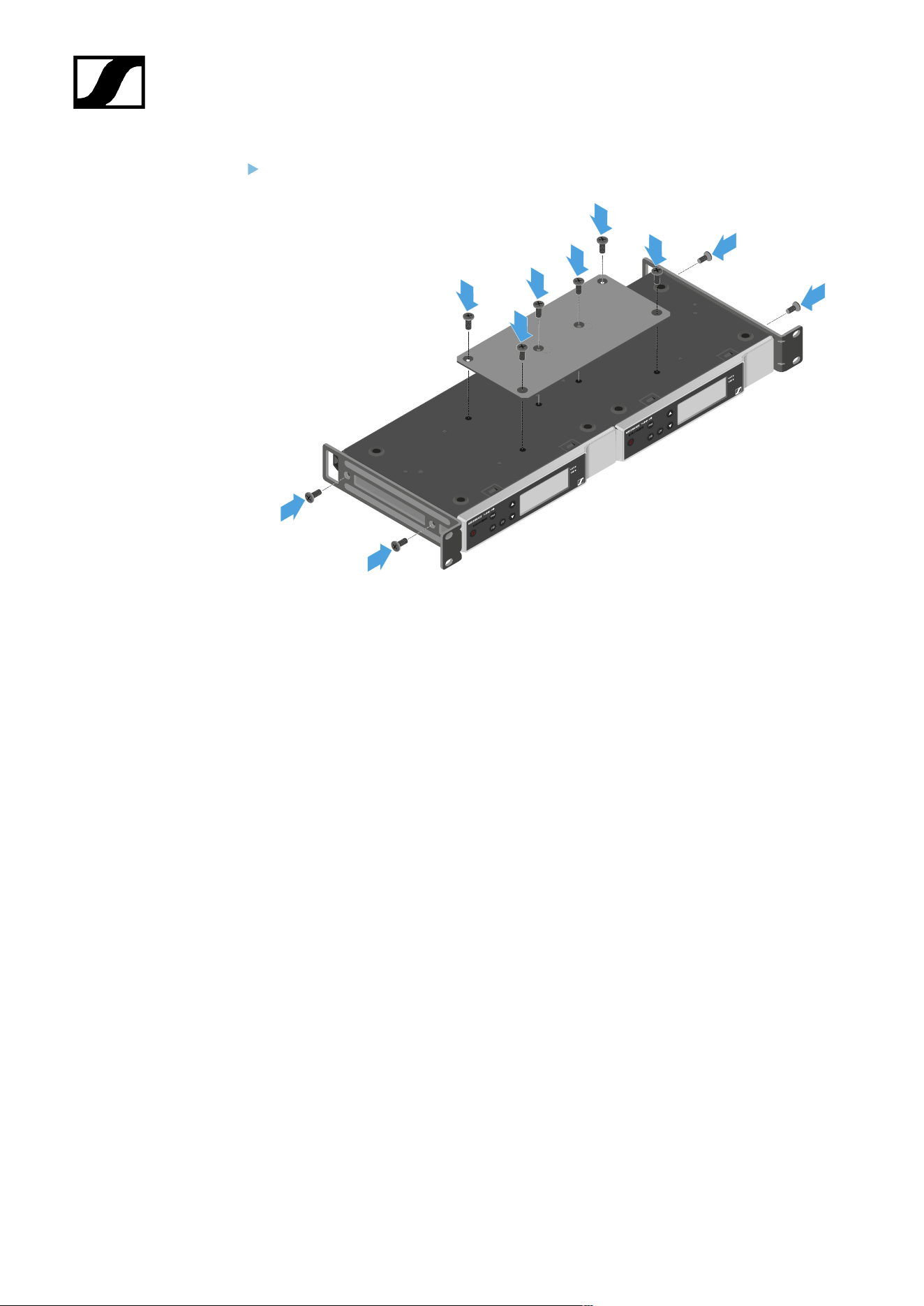
| 3 - Instruction manual
Attach the mounting brackets as shown.
88
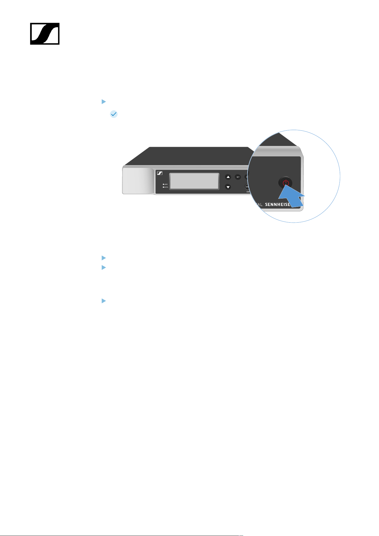
| 3 - Instruction manual
Switching the receiver on and off
To switch the receiver on:
Short-press the ON/OFF button.
The receiver switches on.
To switch the receiver to standby mode:
If necessary, deactivate the lock-off function (see Lock-off function).
Hold down the ON/OFF button until the display switches off.
To switch the receiver off completely:
Disconnect the receiver from the power supply system by unplugging the power
supply unit from the wall socket.
89

| 3 - Instruction manual
Lock-off function
To activate the key lock:
Press the UP and DOWN buttons simultaneously.
Key lock is activated and the lock icon is shown on the display.
To deactivate the key lock:
Simultaneously press the UP and DOWN buttons again.
Key lock is deactivated and the lock icon disappears from the display.
90
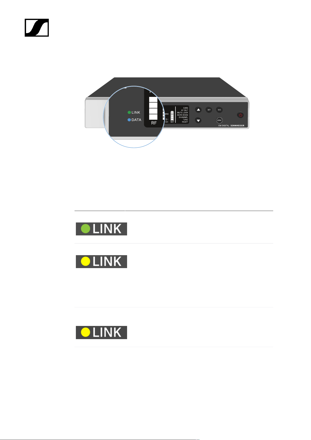
| 3 - Instruction manual
Meaning of the LEDs
The LINK and DATA LEDs on the front of the receiver can indicate the following information.
LINK LED
The LINK LED provides information about the status of the radio link between the transmitter
and receiver, as well as status information for the paired transmitter.
The LED is green:
• The link between the transmitter and receiver is established.
• The audio signal is active.
The LED is yellow:
• The link between the transmitter and receiver is established.
• The audio signal is muted.
or
• No microphone module is mounted on the SKM-S handheld
transmitter.
The LED is flashing
yellow:
• The link between the transmitter and receiver is established.
• The audio signal is overdriven (clipping).
The LED is
continuously red:
• No link between the transmitter and receiver.
91

| 3 - Instruction manual
The LED is flashing
red:
• The battery/rechargeable battery in the paired transmitter is
low.
DATA LED
The DATA LED provides information on the receiver’s Bluetooth Low Energy link to the
Smart Assist app and on the synchronization of transmitters and receivers.
The LED is flashing
blue:
• The Bluetooth Low Energy link is being established
between the receiver and a smartphone or tablet with the
Smart Assist app.
or
• The receiver is being synchronized with a transmitter.
The LED is blue:
• The firmware is being updated.
The LED is off:
• Normal operation
• There is currently no active data link.
92
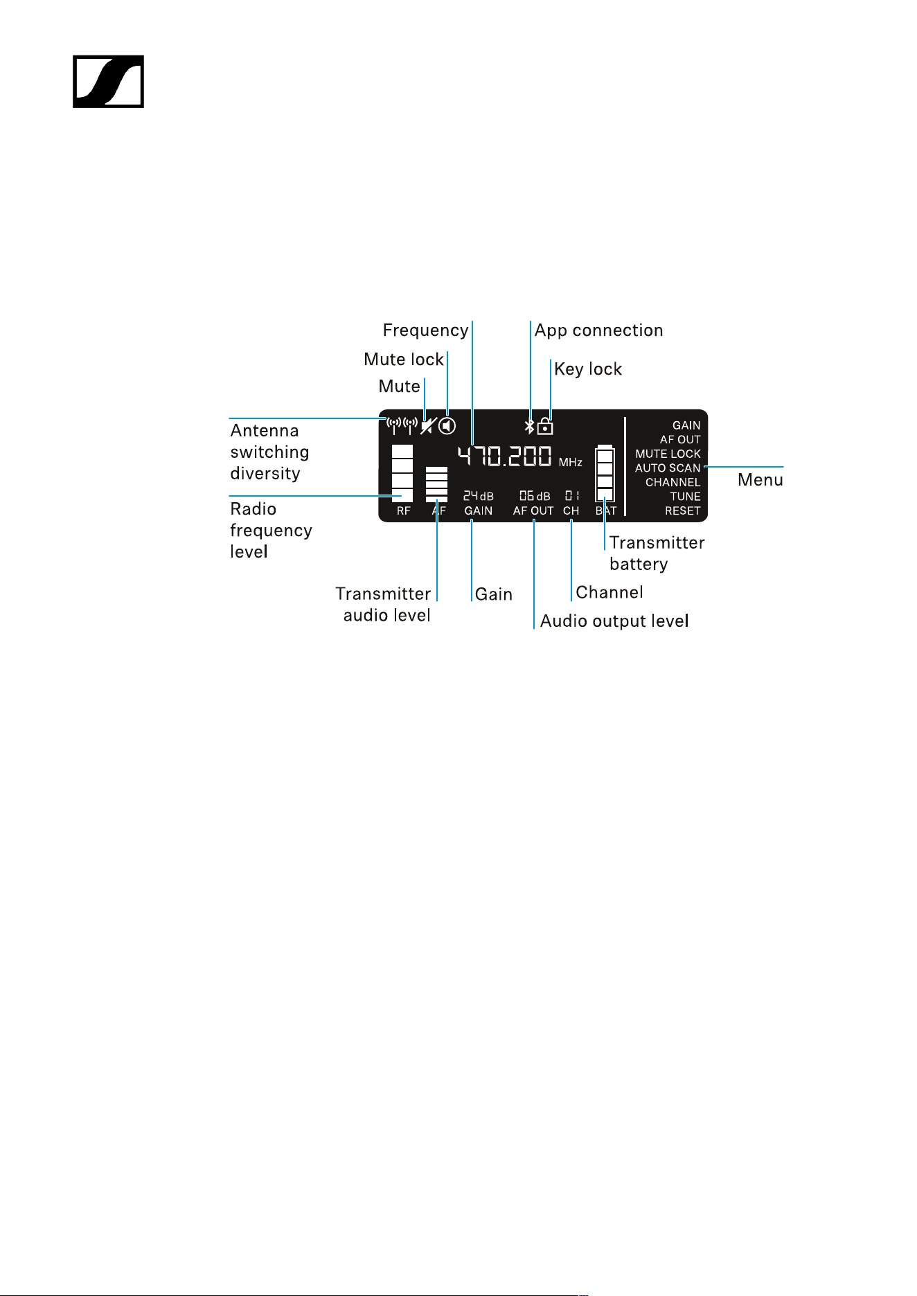
| 3 - Instruction manual
Displays on the receiver’s display panel
Status information such as frequency, reception quality, battery status and audio level is
shown on the display.
The display also shows the operating menu, which you can use to configure all of the settings
(see Buttons for navigating the menu).
Further information
Antenna switching diversity / radio level:
• Establishing a radio link | Synchronizing the receiver and transmitter
Mute / mute lock:
• MUTE LOCK menu item | Muting the handheld transmitter | Muting the bodypack
transmitter
Frequency:
• AUTO SCAN menu item | CHANNEL menu item | TUNE menu item
Connecting to the app:
• Smart Assist app
Lock-off function:
• Lock-off function
Menu:
• Buttons for navigating the menu
93

| 3 - Instruction manual
Transmitter battery
• SKM-S: Inserting and removing the batteries/rechargeable batteries | SK: Inserting
and removing the batteries/rechargeable batteries
Channel:
• CHANNEL menu item
Audio output level:
• AF OUT menu item
Gain:
• GAIN menu item
Transmitter audio level:
• GAIN menu item
94
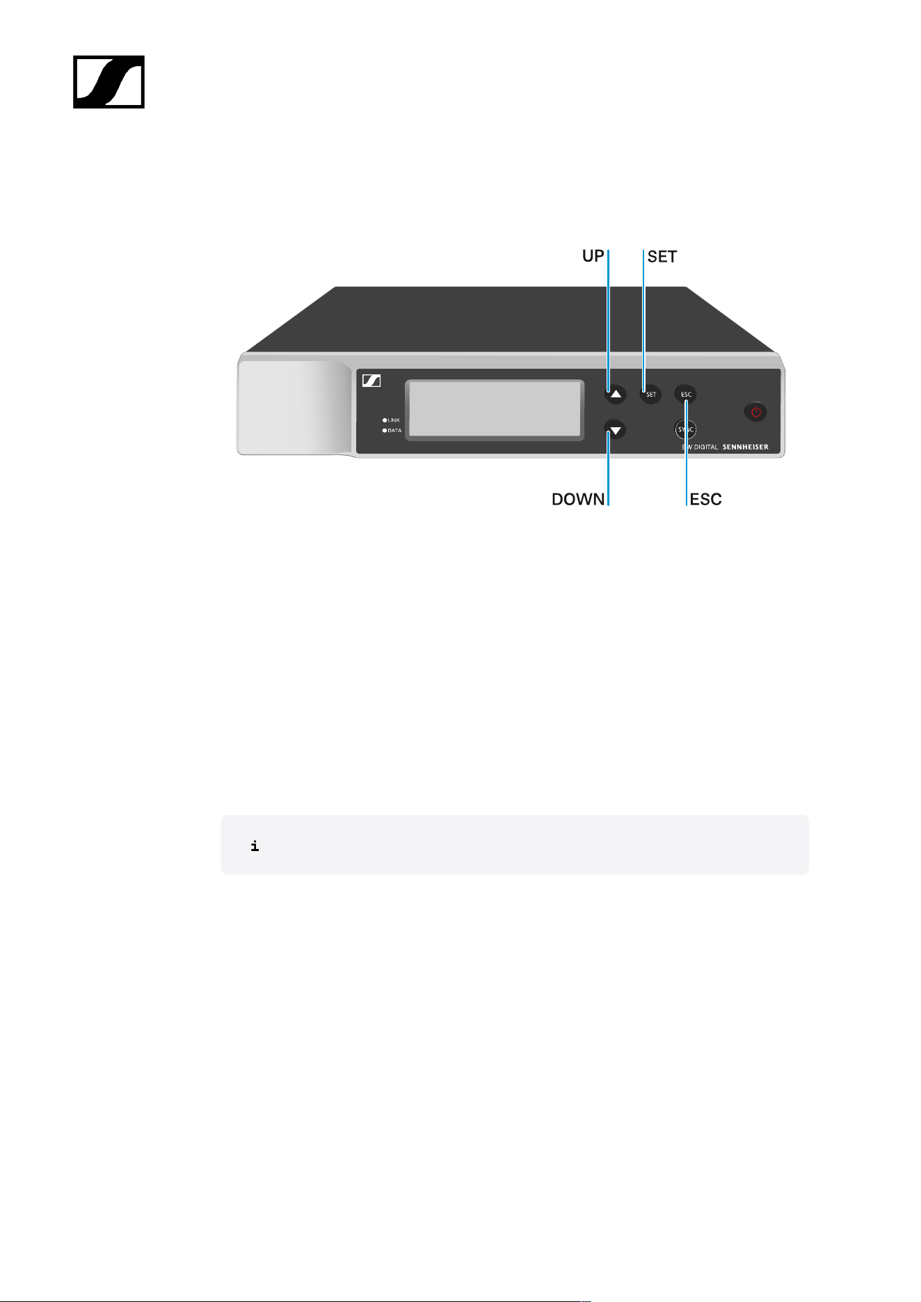
| 3 - Instruction manual
Buttons for navigating the menu
Use the following buttons to navigate through the receiver’s operating menu.
Press the SET button
• Open the menu
• Save settings in a menu item
Press the UP or DOWN button
• Changes to the previous or next menu item
• Changes the setting of a menu item
Press the ESC button
• Cancel input
Opening the menu and navigating the menu items
95
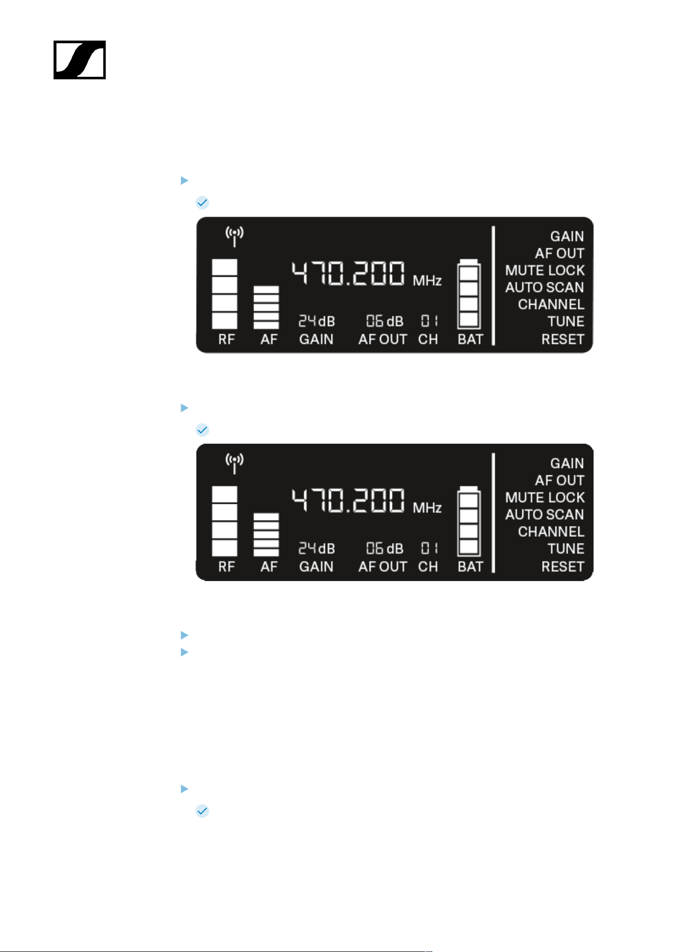
| 3 - Instruction manual
Opening the menu and navigating the menu items
To open the menu:
Press the SET button.
The first menu item GAIN flashes.
To navigate the menu items:
Press the UP and DOWN buttons.
The currently active menu item flashes.
To open a menu item:
Navigate to the desired menu item until it flashes.
Press the SET button to open the selected menu item.
GAIN menu item
Under the GAIN menu item, you can set the level of the audio signal coming from the coupled
transmitter (e.g. vocals via EW-D SKM-S or guitar via EW-D SK).
Open the GAIN menu item.
The item flashes on the display as follows.
96
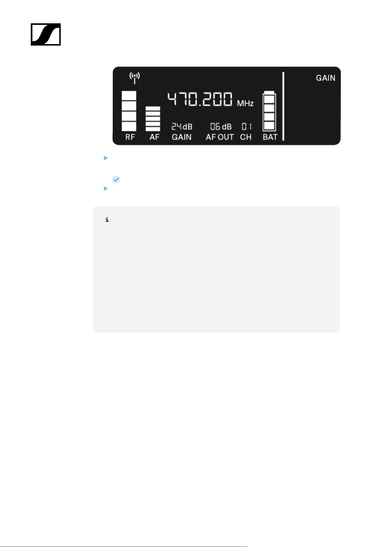
| 3 - Instruction manual
Press the UP or DOWN button to adjust the value. Make sure that the level indicator
AF on the display is not too high.
The LINK LED flashes yellow when the signal is overdriven.
Press the SET button to save the set value.
Recommended settings for a unity gain link:
Unity gain refers to the configuration where the audio signal arriving at a device
leaves the device with the same level.
Example: If you are using an EW-D wireless link instead of a guitar cable, with
unity gain settings, the volume of the guitar in the guitar amplifier will be as high
as it would be if using a guitar cable.
Possible unity gain settings:
• AF Out 18 dB | Gain 27 dB
• AF Out 12 dB | Gain 33 dB
• AF Out 6 dB | Gain 39 dB
97
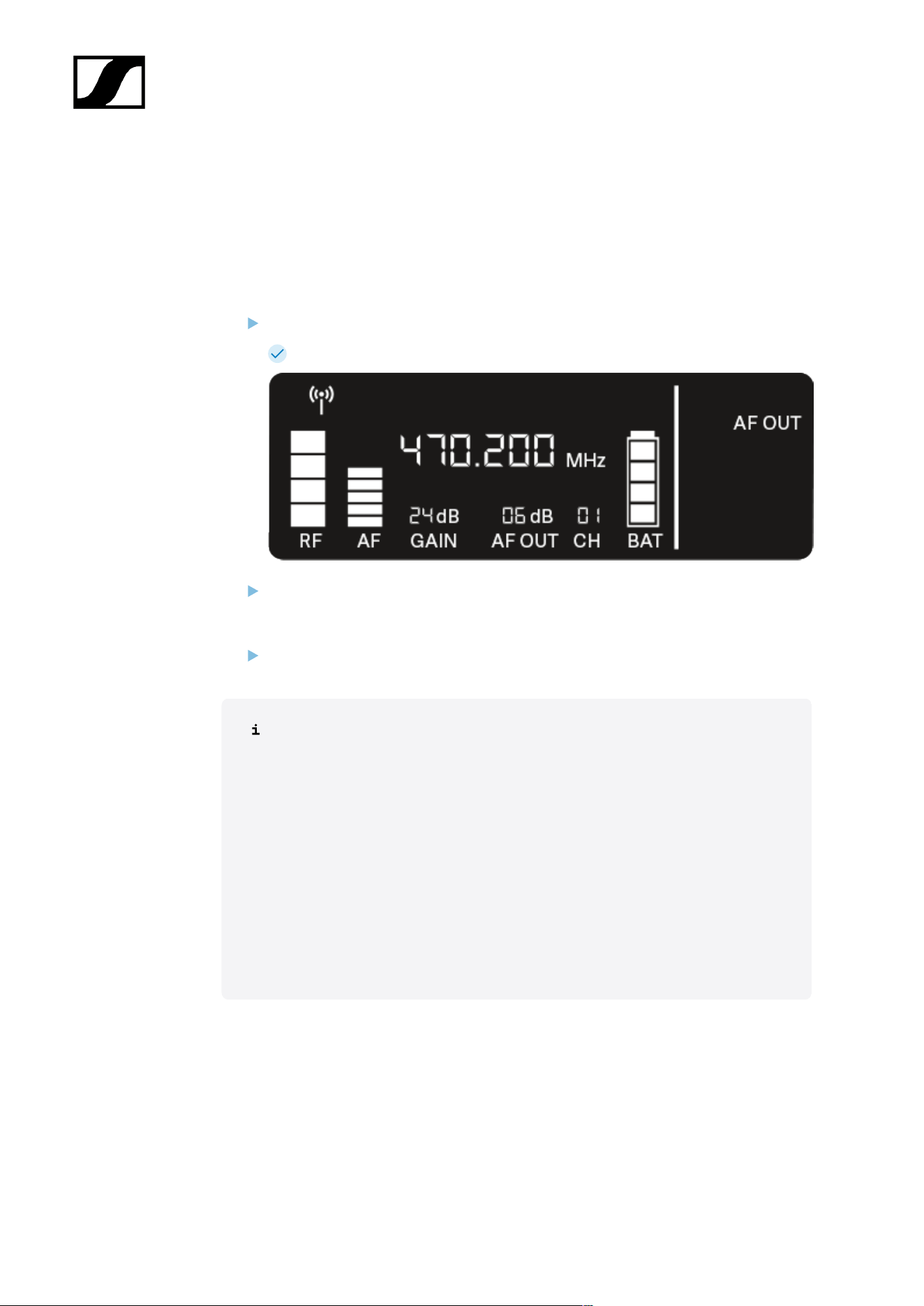
| 3 - Instruction manual
AF OUT menu item
Under the AF OUT menu item, you can set the level of the audio signal coming from the
receiver’s audio outputs (AF out Bal/Unbal). This audio signal can be output to a mixing
console or an amplifier, for example.
Open the AF OUT menu item.
The item flashes on the display as follows.
Press the UP or DOWN button to adjust the value. Make sure that the signal in the
next device in the signal chain (e.g. mixing console, power amplifier, guitar amplifier,
etc.) is not overdriven.
Press the SET button to save the set value.
Recommended settings for a unity gain link:
Unity gain refers to the configuration where the audio signal arriving at a device
leaves the device with the same level.
Example: If you are using an EW-D wireless link instead of a guitar cable, with
unity gain settings, the volume of the guitar in the guitar amplifier will be as high
as it would be if using a guitar cable.
Possible unity gain settings:
• AF Out 18 dB | Gain 27 dB
• AF Out 12 dB | Gain 33 dB
• AF Out 6 dB | Gain 39 dB
98
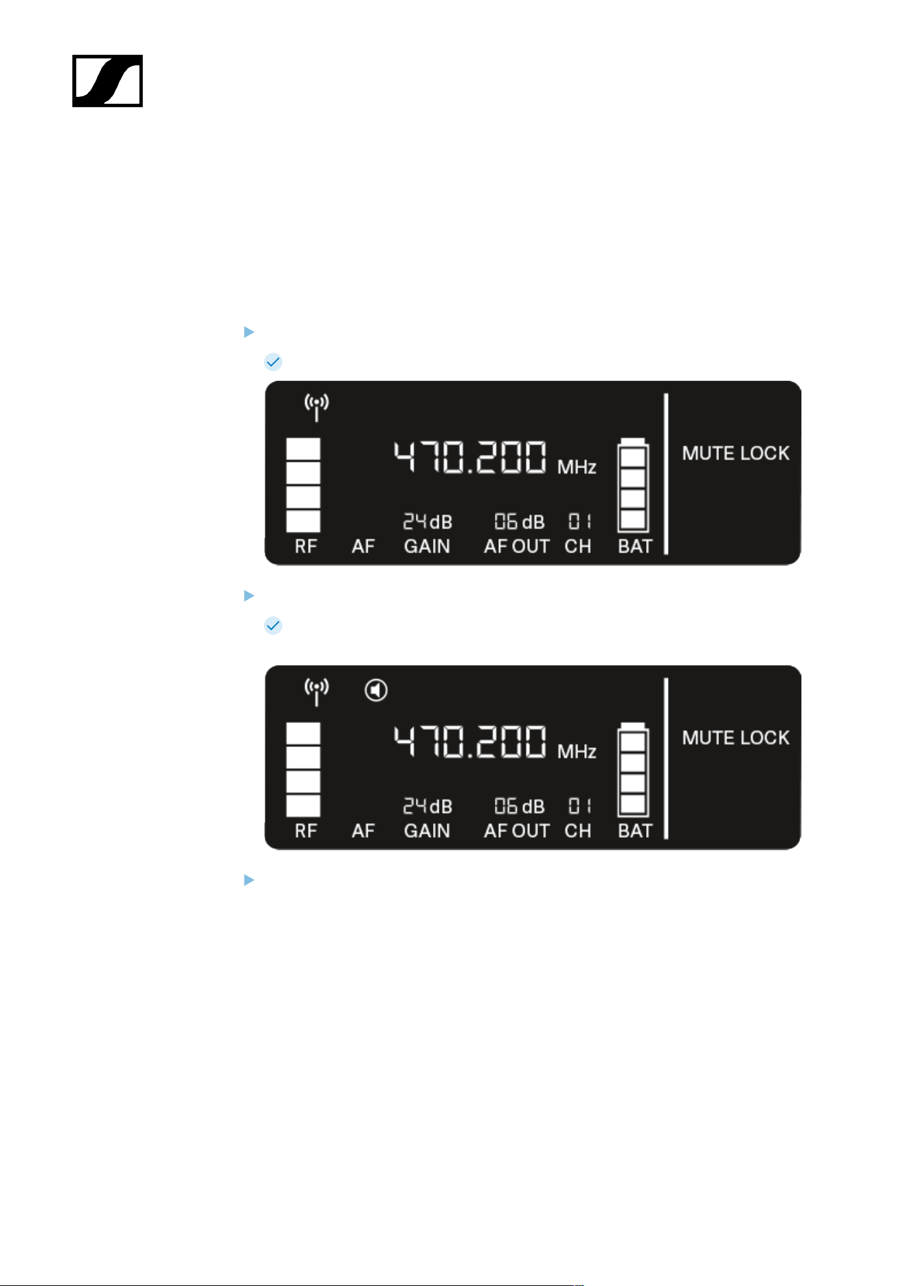
| 3 - Instruction manual
MUTE LOCK menu item
Under the MUTE LOCK menu item, you can disable the mute switch on the paired
transmitter.
The transmitter can then no longer be muted.
Open the MUTE LOCK menu item.
The item flashes on the display as follows.
Press the UP or DOWN button to enable or disable the function.
If the following icon appears on the display, the transmitter’s mute switch is
disabled.
Press the SET button to save the set value.
99
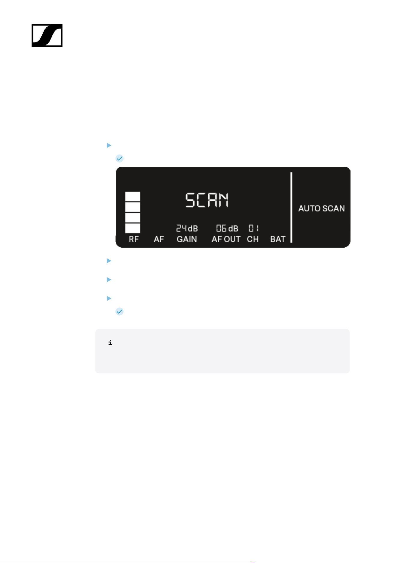
| 3 - Instruction manual
AUTO SCAN menu item
Under the AUTO SCAN menu item, you can perform an automatic frequency scan of your
area. This enables you to easily find and assign free radio frequencies.
The scan starts at the lowest frequency in the device’s frequency range.
Open the AUTO SCAN menu item.
The scan starts automatically. The next free frequency is shown on the display.
Press the SET button to accept the displayed frequency.
Or
Press the UP or DOWN button to display the next free frequency.
Or
Press the ESC button to cancel the scan.
The previous frequency remains unchanged.
If you have set a new frequency, you must still synchronize the receiver with
the transmitter to establish the radio link (see Establishing a radio link |
Synchronizing the receiver and transmitter).
100
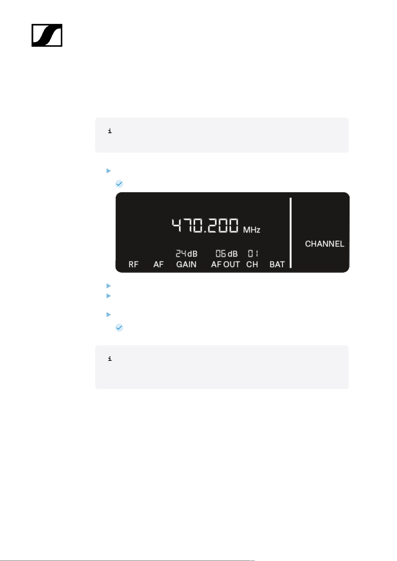
| 3 - Instruction manual
CHANNEL menu item
Under the CHANNEL menu item, you can set the radio frequency by selecting a preset
channel.
If you are not sure whether the selected frequency is free, we recommend
performing a scan to detect all free frequencies: AUTO SCAN menu item.
Open the CHANNEL menu item.
The item flashes on the display as follows.
Press the UP or DOWN button to select a preset channel.
Press the SET button to accept the displayed frequency.
Or
Press the ESC button to cancel the scan.
The previous frequency remains unchanged.
If you have set a new frequency, you must still synchronize the receiver with
the transmitter to establish the radio link (see Establishing a radio link |
Synchronizing the receiver and transmitter).
101
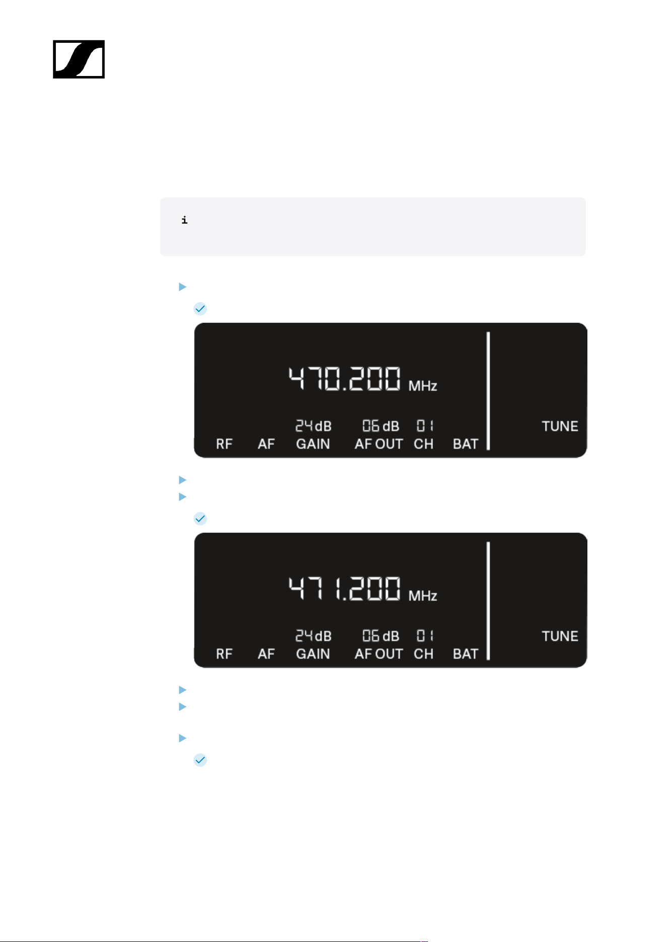
| 3 - Instruction manual
TUNE menu item
Under the TUNE menu item, you can manually set the radio frequency independently of the
preset channels.
If you are not sure whether the selected frequency is free, we recommend
performing a scan to detect all free frequencies: AUTO SCAN menu item.
Open the TUNE menu item.
The item flashes on the display as follows.
Press the UP or DOWN button to set the frequency in the megahertz range.
Press the SET button to save the set value.
The item flashes on the display as follows.
Press the UP or DOWN buttons to finely adjust the frequency in the kilohertz range.
Press the SET button to accept the displayed frequency.
Or
Press the ESC button to cancel the scan.
The previous frequency remains unchanged.
102

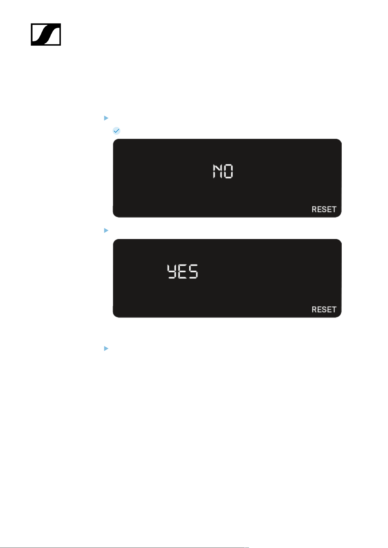
| 3 - Instruction manual
RESET menu item
Under the RESET menu item, you can reset the receiver to its factory settings.
Open the RESET menu item.
The item flashes on the display as follows.
Press the UP or DOWN button to switch between the options YES and NO.
• YES: The receiver is reset to its factory settings.
• NO: The receiver is not reset.
Press the SET button to save the set value.
104

| 3 - Instruction manual
Using EW-D Color Coding Sets to label transmission paths
You can use the EW-D Color Coding Sets (see Color Coding Sets) to identify which
transmitters belong to which receivers. This makes it easier to match up the individual
devices, especially in multi-channel systems.
You can also assign colors to the devices in the Smart Assist app.
105
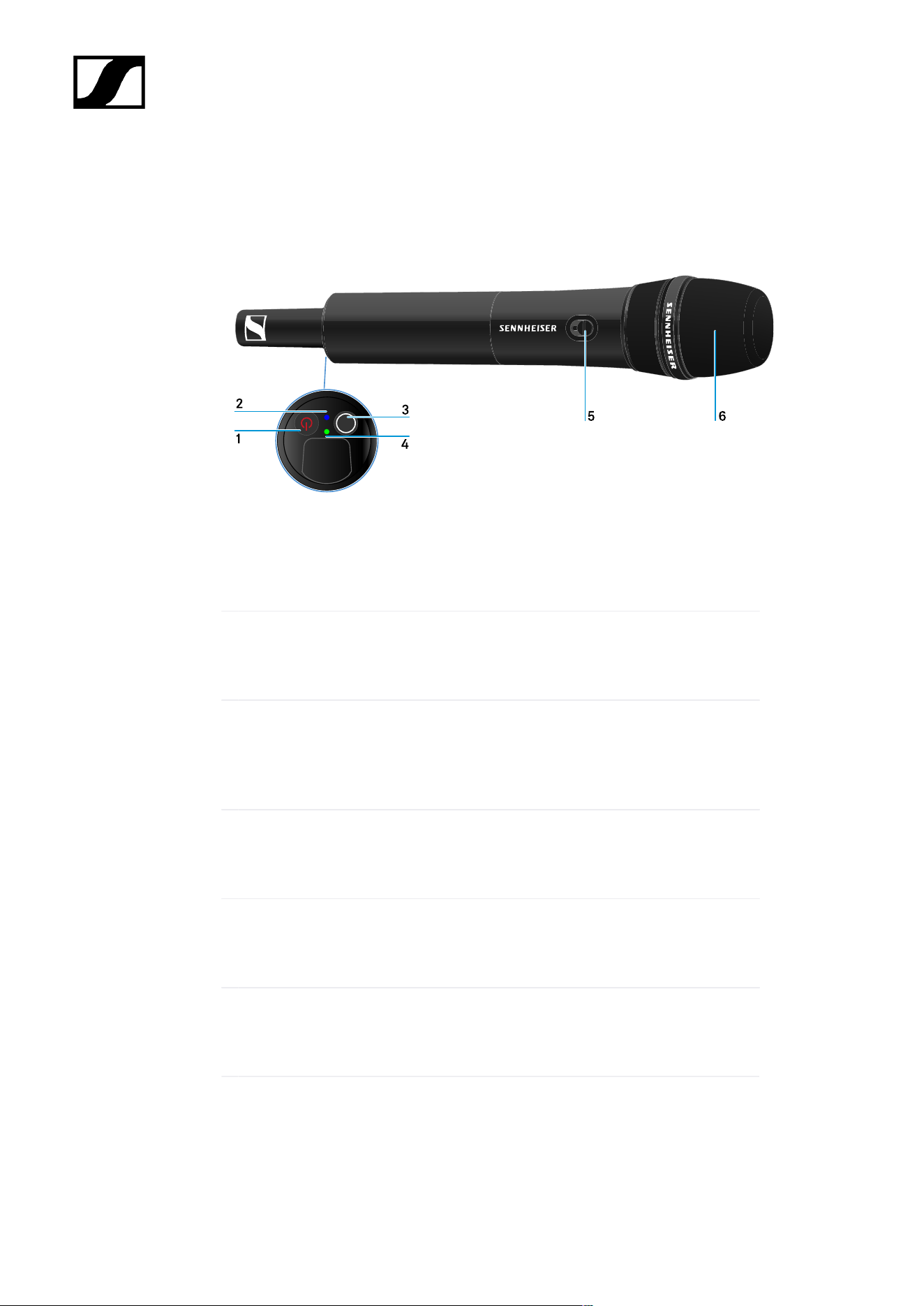
| 3 - Instruction manual
EW-D SKM-S handheld transmitter
Product overview
1 ON/OFF button
• See Switching the handheld transmitter on and off
2 DATA LED
• See Meaning of the LEDs
3 SYNC button
• See Establishing a radio link | Synchronizing the receiver and
transmitter
4 LINK LED
• See Meaning of the LEDs
5 Mute switch
• See Muting the handheld transmitter
6 Microphone module
• See Replacing the microphone module
106
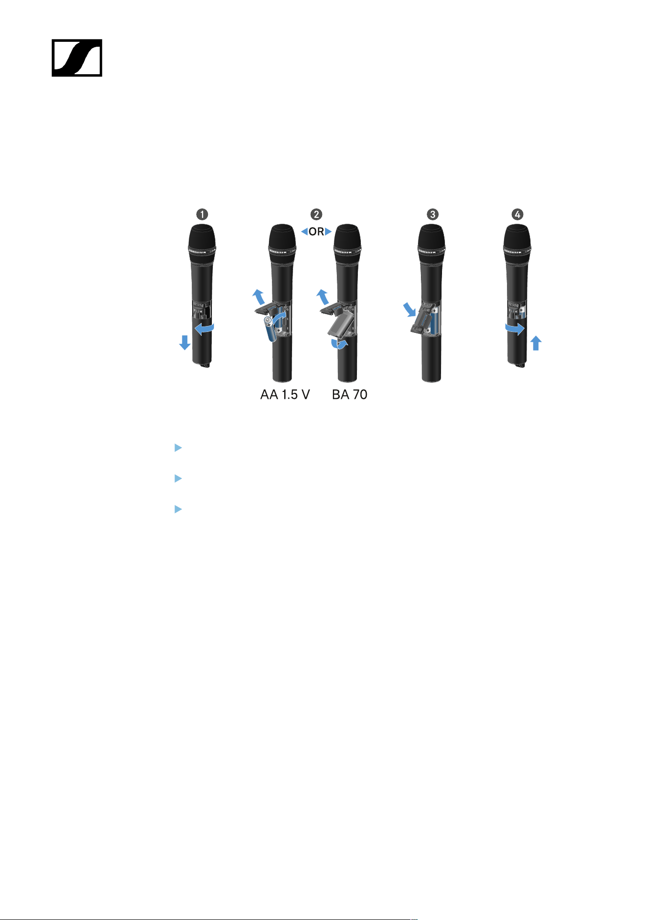
| 3 - Instruction manual
Inserting and removing the batteries/rechargeable batteries
You can operate the handheld transmitter either with batteries (AA, 1.5 V) or with the
rechargeable Sennheiser BA 70 battery.
Unscrew the microphone housing as shown in the figure and pull it down as far as it
will go.
Insert the batteries or the BA 70 rechargeable battery as indicated in the battery
compartment. Observe correct polarity.
Screw the microphone housing back on.
107

| 3 - Instruction manual
Note about the BA 70 rechargeable battery
• Make sure that the BA 70 rechargeable battery is inserted as follows:
108
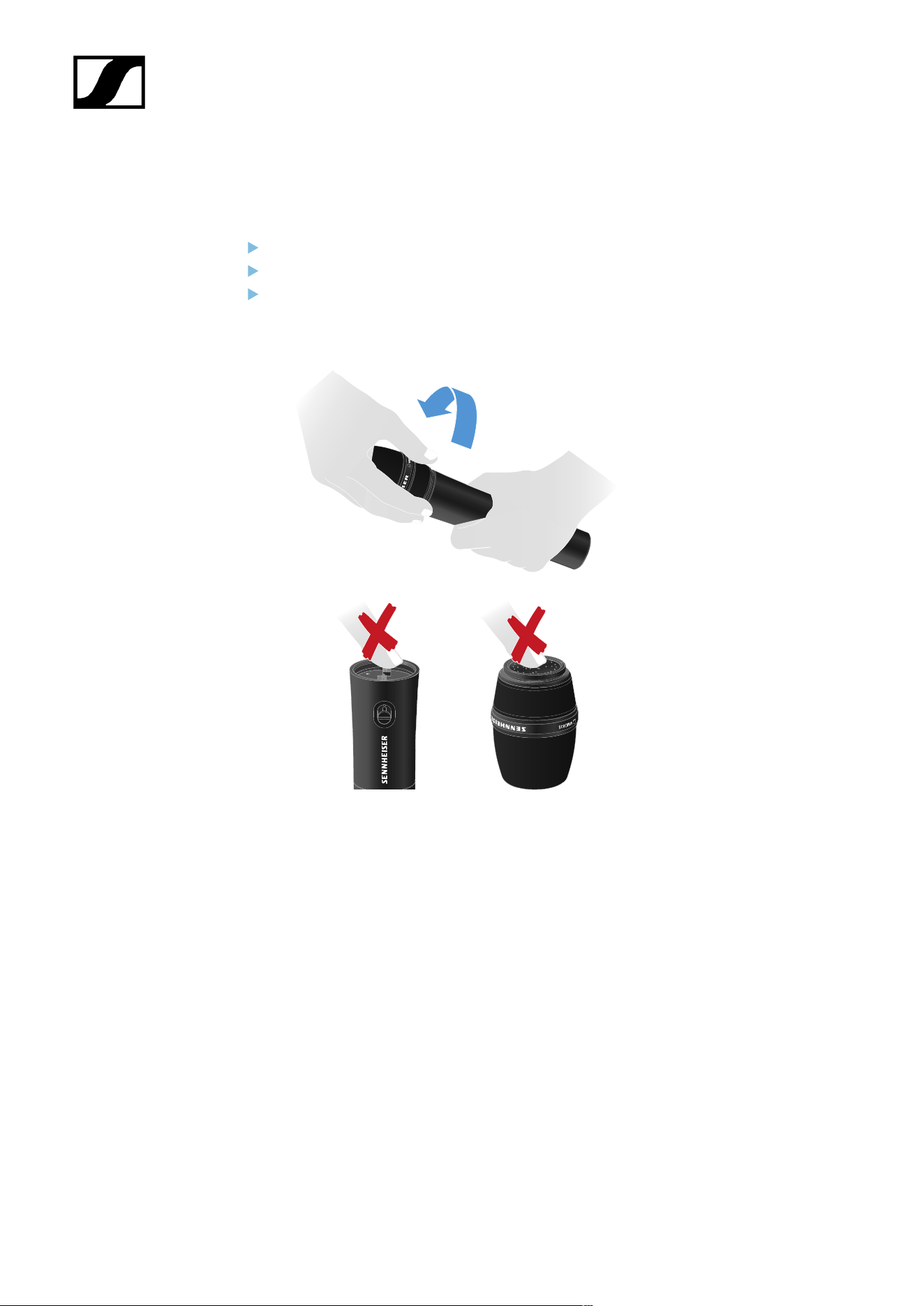
| 3 - Instruction manual
Replacing the microphone module
To replace the microphone module:
Unscrew the microphone module.
Screw the desired microphone module on.
Do not touch the wireless microphone contacts or the microphone module contacts. If
you touch the contacts, they may become dirty or bent.
Compatible microphone modules
The following microphone modules are compatible with the handheld transmitter:
• MMD 835-1 | Dynamic microphone module with cardioid pattern
• MMD 845-1 | Dynamic microphone module with super-cardioid pick-up pattern
• MME 865-1 | Condenser microphone module with super-cardioid pick-up pattern
• MMD 935-1 | Dynamic microphone module with cardioid pattern
• MMD 945-1 | Dynamic microphone module with super-cardioid pick-up pattern
• MMK 965-1 | Condenser microphone module with selectable pattern: cardioid and
super-cardioid
• MMD 42-1 | Dynamic microphone module with omni-directional pattern
• Neumann KK 204 | Condenser microphone module with cardioid pattern
109

| 3 - Instruction manual
• Neumann KK 205 | Condenser microphone module with super-cardioid pick-up
pattern
• MM 435 | Dynamic microphone module with cardioid pattern
• MM 445 | Dynamic microphone module with super-cardioid pick-up pattern
• ME 9002 | Condenser microphone module with omni-directional pattern
• ME 9004 | Condenser microphone module with cardioid pattern
• ME 9005 | Condenser microphone module with super-cardioid pick-up pattern
110

| 3 - Instruction manual
Using EW-D Color Coding Sets to label transmission paths
You can use the EW-D Color Coding Sets (see Color Coding Sets) to identify which
transmitters belong to which receivers. This makes it easier to match up the individual
devices, especially in multi-channel systems.
You can also assign colors to the devices in the Smart Assist app.
111
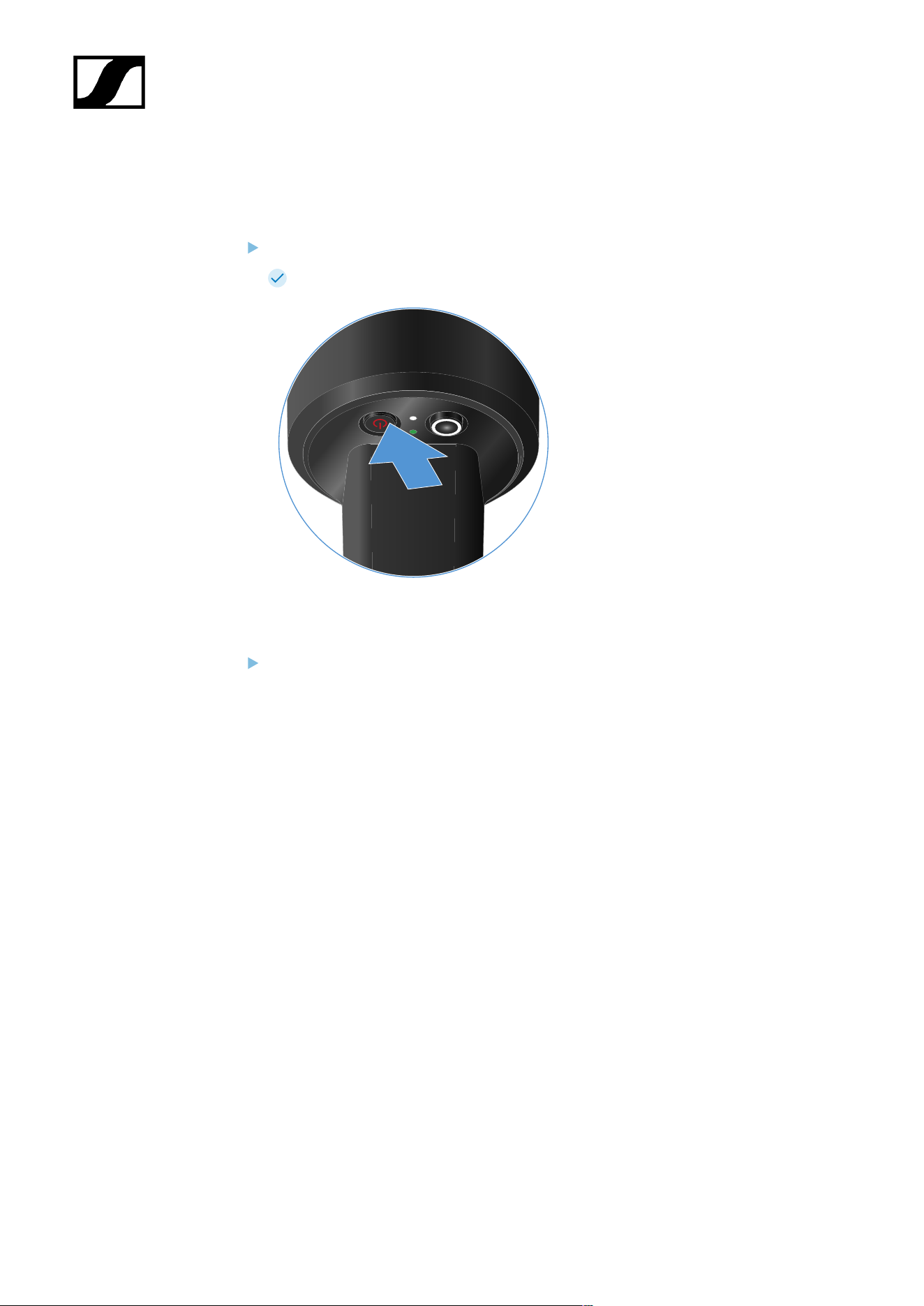
| 3 - Instruction manual
Switching the handheld transmitter on and off
To switch the handheld transmitter on:
Short-press the ON/OFF button.
The LINK LED lights up and the transmitter switches on.
To switch the handheld transmitter off:
Hold down the ON/OFF button until the LEDs switch off.
112
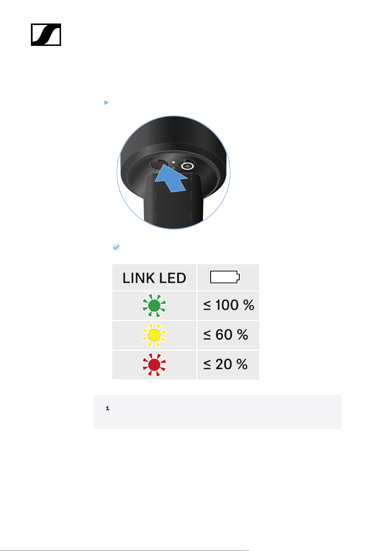
| 3 - Instruction manual
Checking the battery status of the transmitter (Check function)
To check the battery status of the transmitter:
Short-press the ON/OFF button on the transmitter.
The transmitter’s LINK LED flashes to indicate the current charge level of the
battery or the BA 70 rechargeable battery.
Pressing the transmitter’s ON/OFF button will simultaneously trigger the Identify
function: Identifying the paired receiver (Identify function).
113
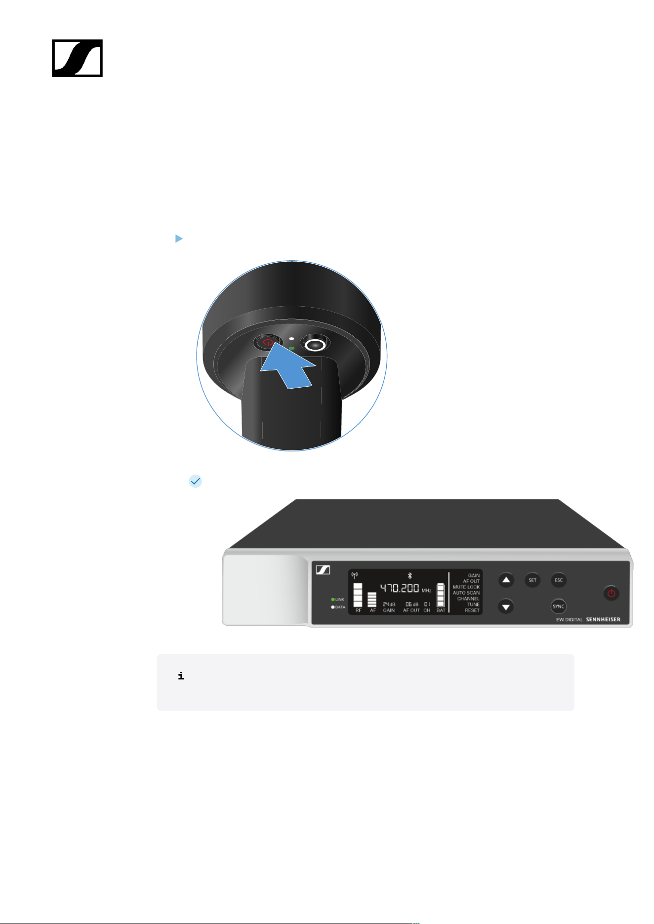
| 3 - Instruction manual
Identifying the paired receiver (Identify function)
In multi-channel systems, you can use the Check function to quickly identify to which
receiver the transmitter is paired.
Both the transmitter and receiver must be switched on.
Short-press the ON/OFF button on the transmitter.
The display on the paired receiver starts flashing.
Pressing the transmitter’s ON/OFF button will simultaneously trigger the Check
function: Checking the battery status of the transmitter (Check function).
114
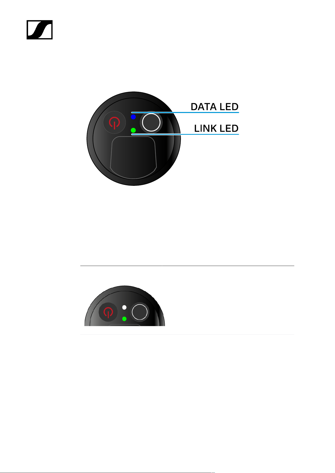
| 3 - Instruction manual
Meaning of the LEDs
The LINK and DATA LEDs on the bottom of the transmitter can indicate the following
information.
LINK LED
The LINK LED provides information about the status of the radio link between the transmitter
and receiver, as well as status information for the paired transmitter.
The LED is green:
• The link between the transmitter and receiver is
established.
• The transmission frequency is active.
The LED is yellow:
• The link between the transmitter and receiver is
established.
• The audio signal is muted or
• No microphone module is mounted on the
SKM-S handheld transmitter.
115

| 3 - Instruction manual
The LED is flashing yellow:
• The link between the transmitter and receiver is
established.
• The audio signal is overdriven (clipping).
The LED is continuously red:
• The (rechargeable) battery in the transmitter is
dead.
The LED is flashing red:
• The link between the transmitter and receiver is
established.
• The battery/rechargeable battery in the
transmitter is low.
The LED is off:
• No link between the transmitter and receiver.
• The transmitter is switched off.
DATA LED
The DATA LED provides information about the synchronization of transmitters and receivers.
116
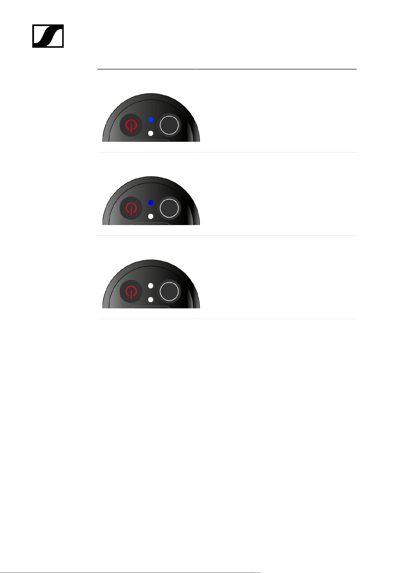
| 3 - Instruction manual
The LED is flashing blue:
• The transmitter is being synchronized with a
receiver.
The LED is blue:
• The firmware is being updated.
The LED is off:
• There is currently no active data link.
117

| 3 - Instruction manual
Establishing a connection to the receiver
To establish a radio link between the transmitter and the receiver, the devices must be
synchronized.
See Establishing a radio link | Synchronizing the receiver and transmitter
Conditions and restrictions for using frequencies
There may be special conditions and restrictions for using frequencies in your
country.
Before putting the product into operation, find the information for your country
at the following address:
sennheiser.com/sifa
118
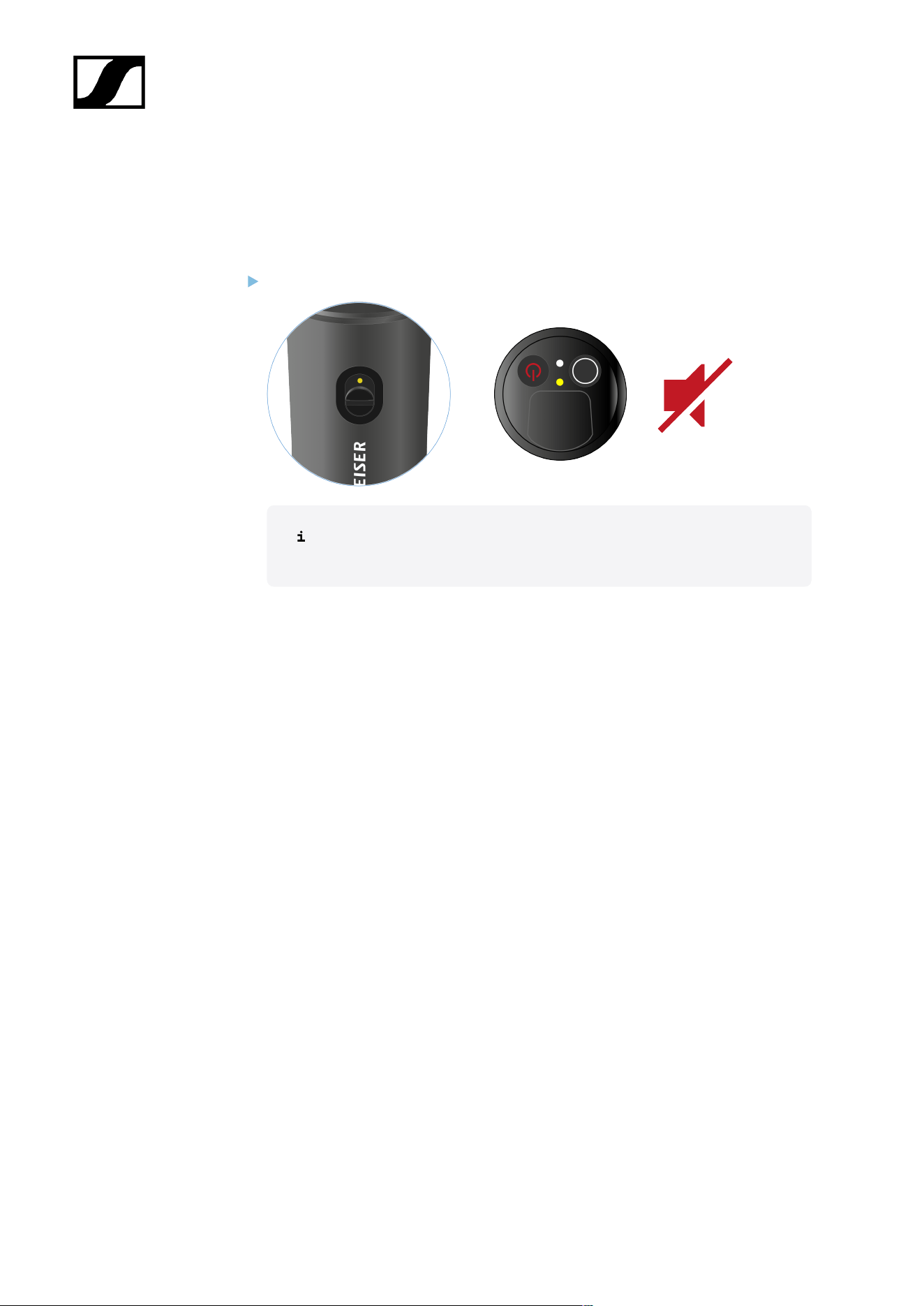
| 3 - Instruction manual
Muting the handheld transmitter
You can mute the audio signal using the mute switch.
Slide the mute switch to the desired position to mute or activate the audio signal.
You can disable the mute switch by activating the MUTE LOCK option on
the receiver (see MUTE LOCK menu item).
119
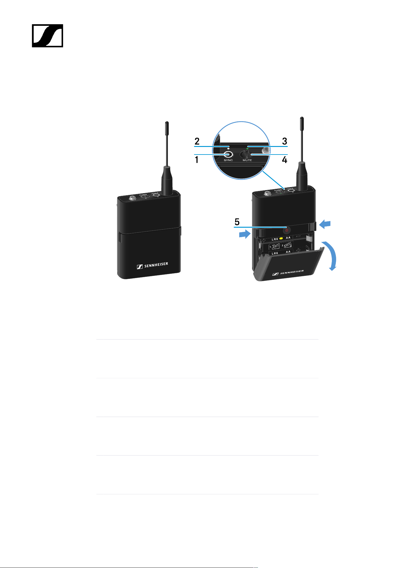
| 3 - Instruction manual
EW-D SK bodypack transmitter
Product overview
1 SYNC button
• See Establishing a radio link | Synchronizing the receiver and
transmitter
2 DATA LED
• See Meaning of the LEDs
3 LINK LED
• See Meaning of the LEDs
4 Mute switch
• See Muting the bodypack transmitter
5 ON/OFF button
• See Switching the bodypack transmitter on and off
120
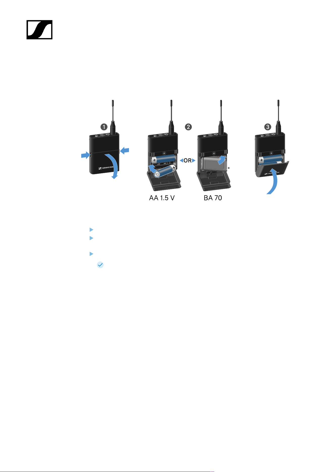
| 3 - Instruction manual
Inserting and removing the batteries/rechargeable batteries
You can operate the handheld transmitter either with batteries (AA, 1.5 V) or with the
rechargeable Sennheiser BA 70 battery.
Press the two catches and open the battery compartment cover.
Insert the batteries or the BA 70 rechargeable battery as indicated in the battery
compartment. Observe correct polarity.
Close the battery compartment.
The cover locks into place with an audible click.
121
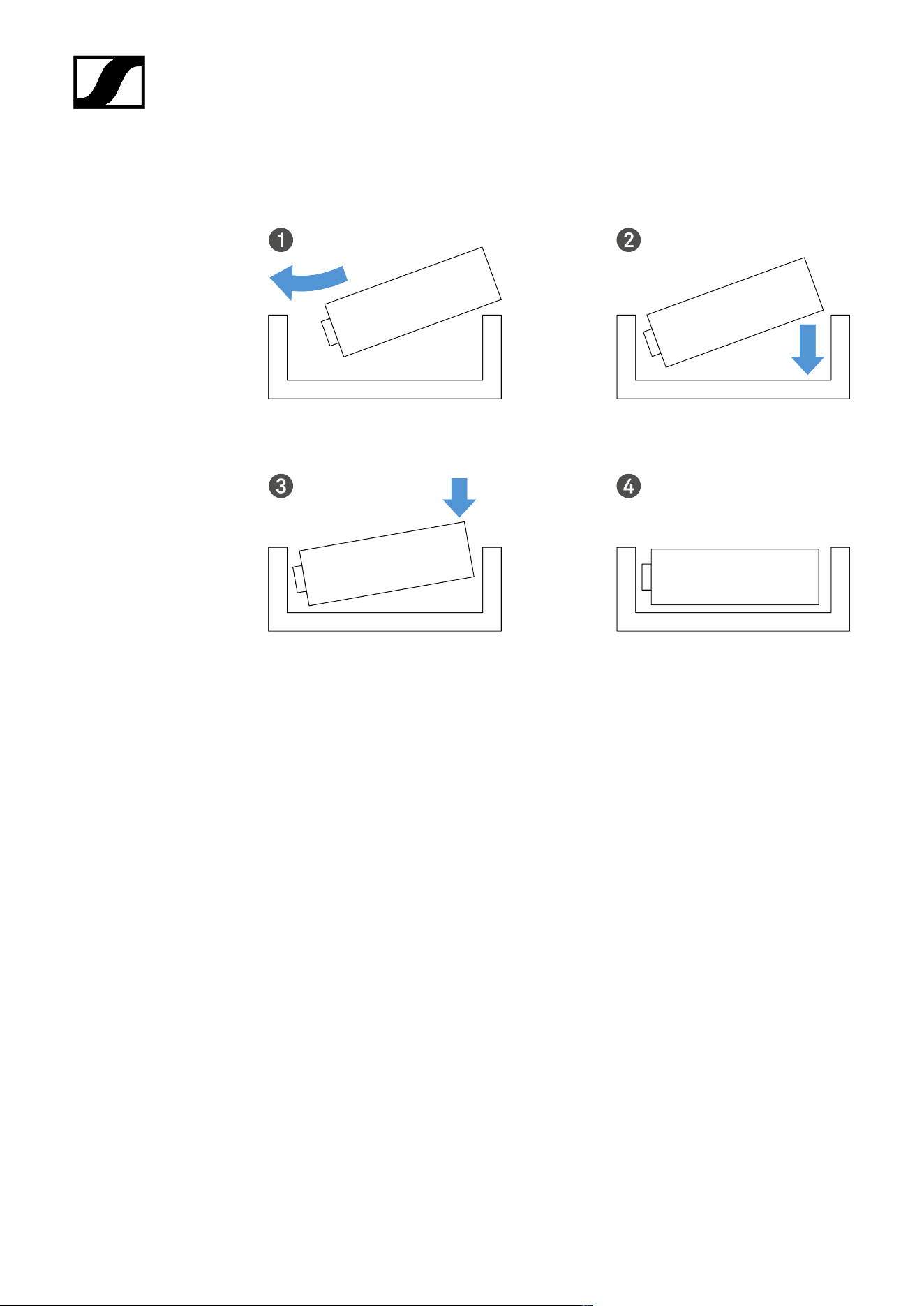
| 3 - Instruction manual
Note about the BA 70 rechargeable battery
• Make sure that the BA 70 rechargeable battery is inserted as follows:
122
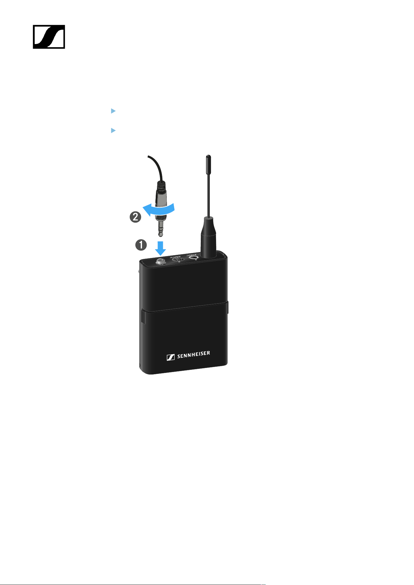
| 3 - Instruction manual
Connecting a microphone to the bodypack transmitter
To connect a microphone to the bodypack transmitter:
Insert the cable’s 3.5 mm jack plug into the socket on the bodypack transmitter as
shown in the diagram.
Screw the plug’s coupling ring onto the audio socket thread of the bodypack
transmitter.
Compatible microphones
The following microphones are compatible with the bodypack transmitter:
Lavalier microphones:
• ME 2 | Lavalier microphone with omni-directional pattern (models from 2021 and later
with gold-plated plug*)
• ME 4 | Lavalier microphone with cardioid pattern (models from 2021 and later with
gold-plated plug*)
• MKE Essential Omni | Lavalier microphone with omni-directional pattern
• MKE 2 Gold | Lavalier microphone with omni-directional pattern (models from 2018
and later with blue serial number label)
• MKE 1 | Lavalier microphone with omni-directional pattern
123

| 3 - Instruction manual
Headset microphones:
• ME 3 | Headset microphone with cardioid pattern (models from 2021 and later with
gold-plated plug*)
• HSP Essential Omni | Headset microphone with omni-directional pattern
• HSP 2 | Headset microphone with omni-directional pattern (models from March 2020
and later with code 1090 or higher)
• HS 2 | Headset microphone with omni-directional pattern (models from 2021 and later
with gold-plated plug*)
• SL Headmic 1 | Headset microphone with omni-directional pattern
*Pre-2021 models with a nickel plug are not recommended. They can pick up noise if they are
placed too close to the transmitter.
124
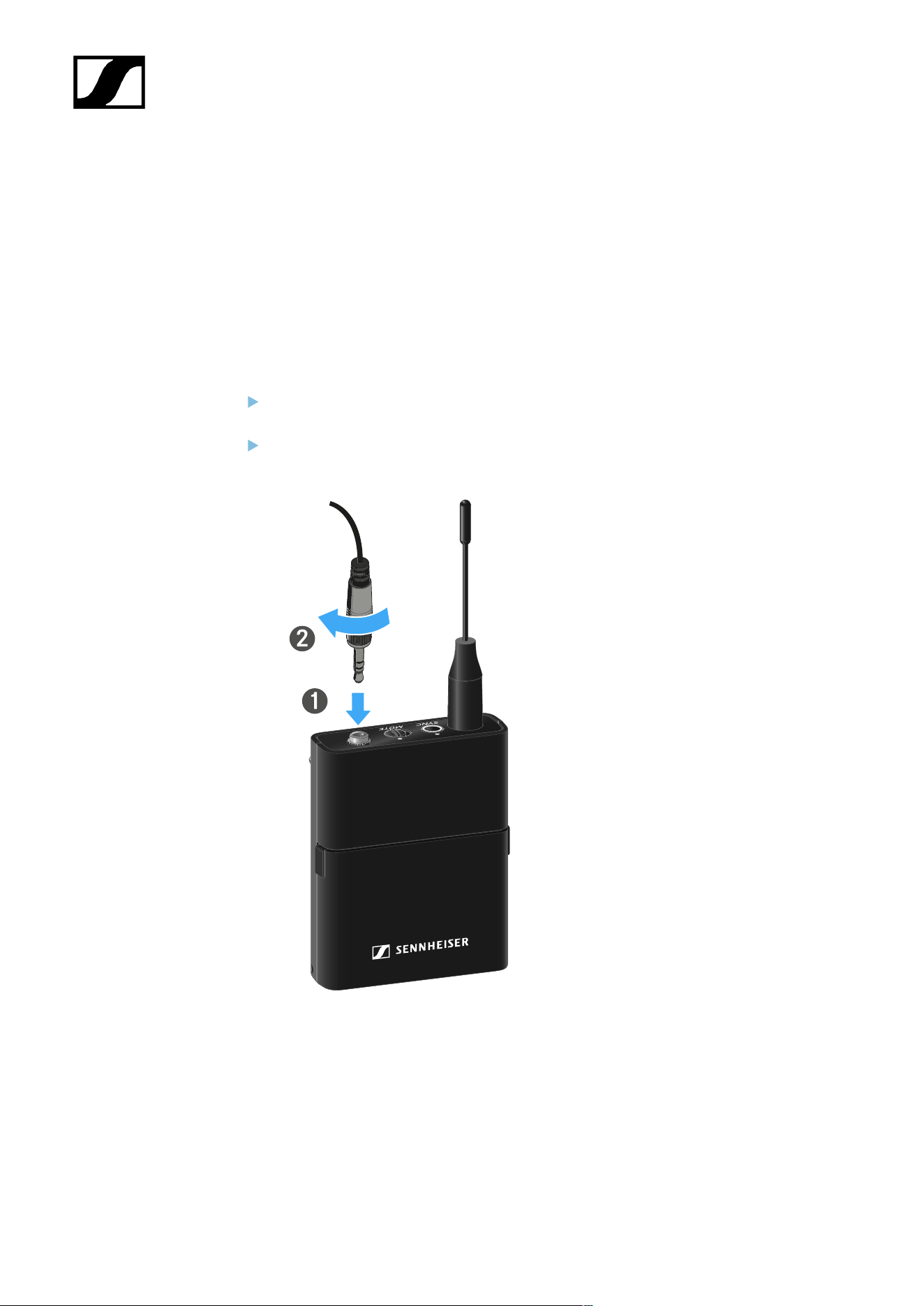
| 3 - Instruction manual
Connecting an instrument or line source to the bodypack
transmitter
You can connect instruments or audio sources with a line level to the bodypack transmitter.
To do this, you will need the CI 1 (6.3 mm jack plug on a lockable 3.5 mm jack plug) or CL 2
(XLR-3F plug on a lockable 3.5 mm jack plug) Sennheiser cables.
To connect an instrument or line source to bodypack transmitter:
Insert the cable’s 3.5 mm jack plug into the socket on the bodypack transmitter as
shown in the diagram.
Screw the plug’s coupling ring onto the audio socket thread of the bodypack
transmitter.
125
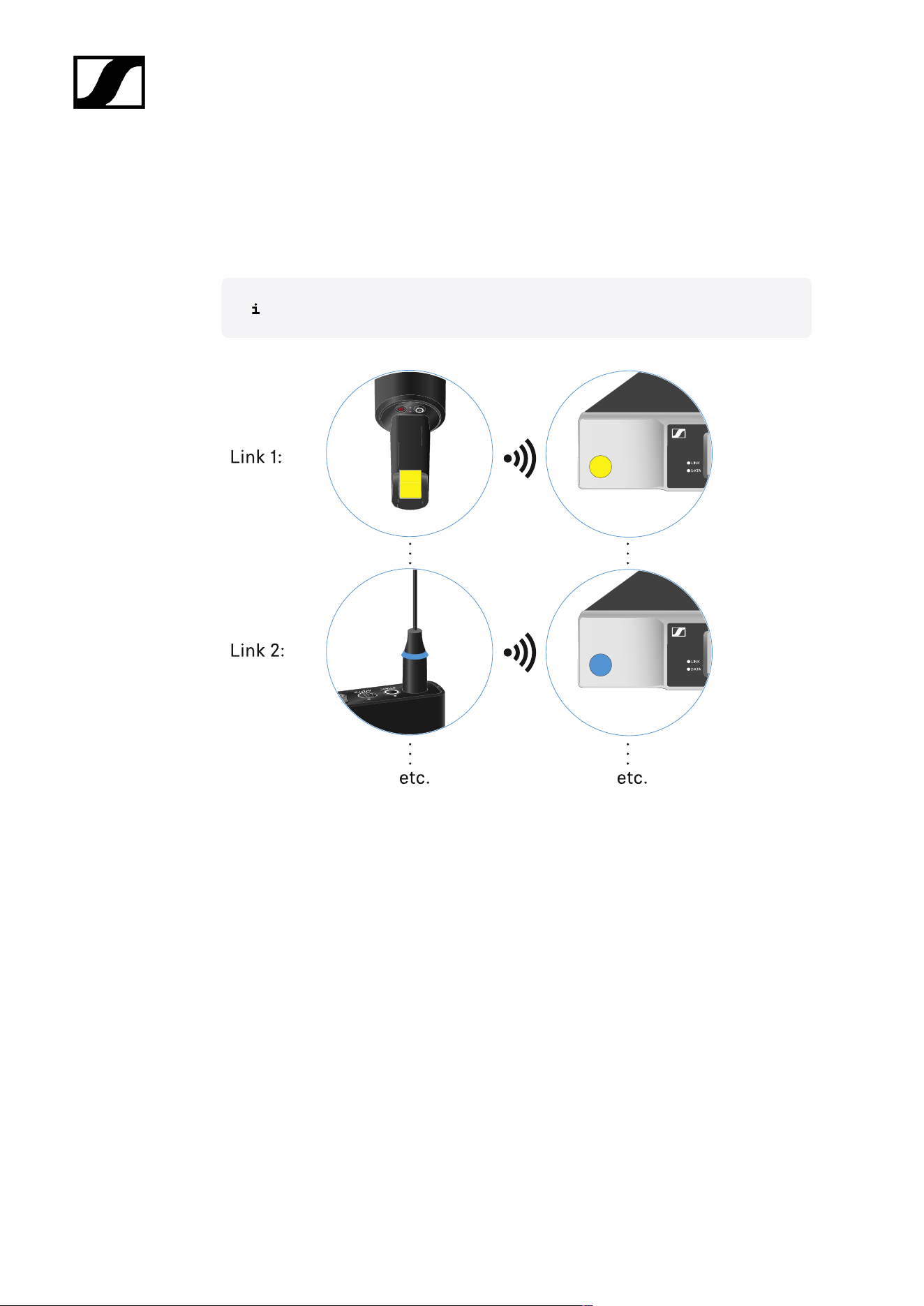
| 3 - Instruction manual
Using EW-D Color Coding Sets to label transmission paths
You can use the EW-D Color Coding Sets (see Color Coding Sets) to identify which
transmitters belong to which receivers. This makes it easier to match up the individual
devices, especially in multi-channel systems.
You can also assign colors to the devices in the Smart Assist app.
126
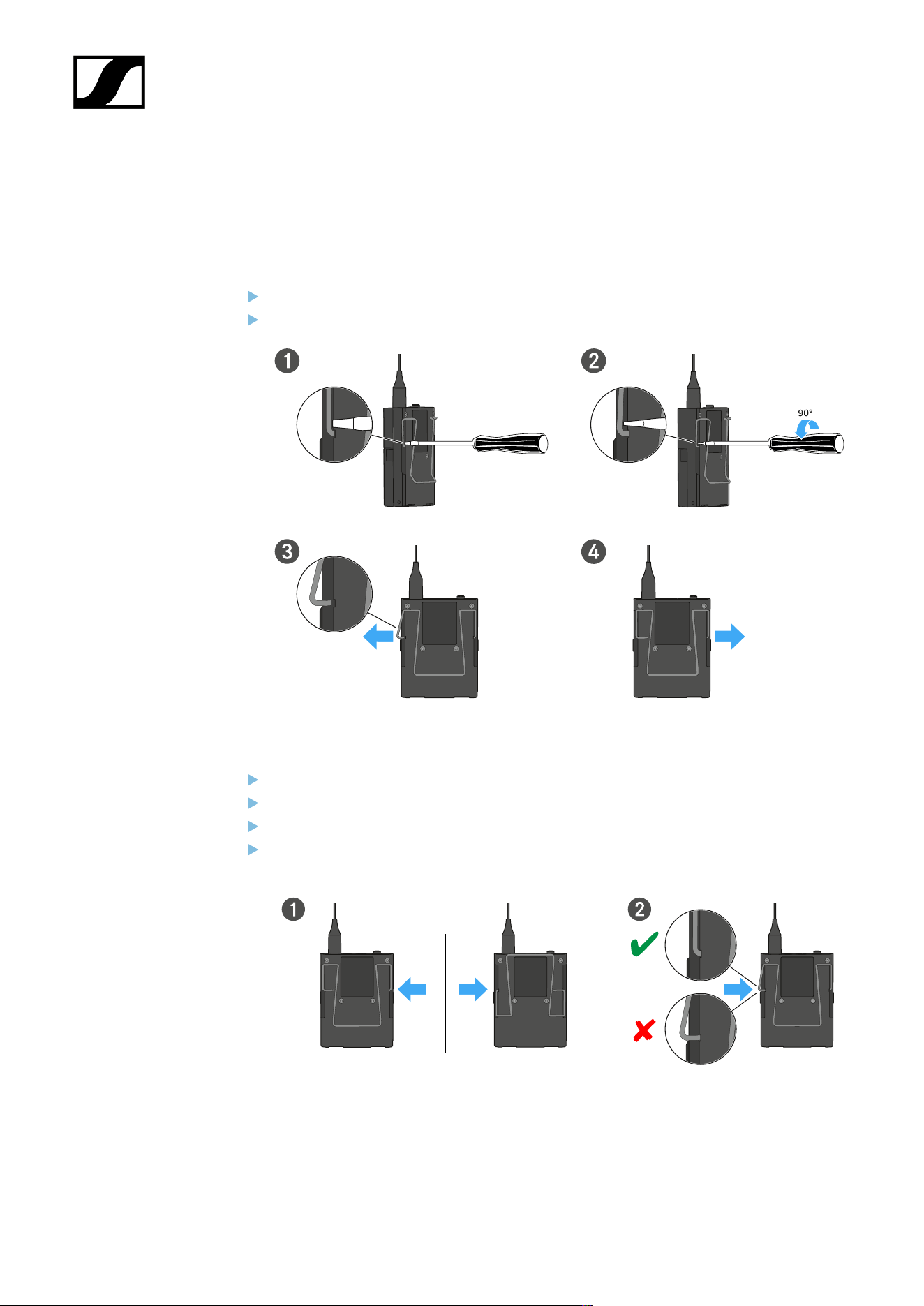
| 3 - Instruction manual
Changing the belt clip
You can change the belt clip on the bodypack transmitter or flip it over depending on how
you want to wear it.
To remove the belt clip:
Carefully loosen the belt clip with a small screwdriver as shown in the figure.
Be very careful not to scratch the housing.
To insert the belt clip:
Insert one side of the belt clip first as shown in the figure.
Then insert the second side of the belt clip.
Gently press the belt clip all the way in on both sides.
Always insert one side before the other, not at the same time, as otherwise the belt
clip could bend.
127

| 3 - Instruction manual
Switching the bodypack transmitter on and off
To switch the bodypack transmitter on:
Short-press the ON/OFF button.
The LINK LED lights up and the transmitter switches on.
To switch the bodypack transmitter off:
Hold down the ON/OFF button until the LEDs switch off.
128
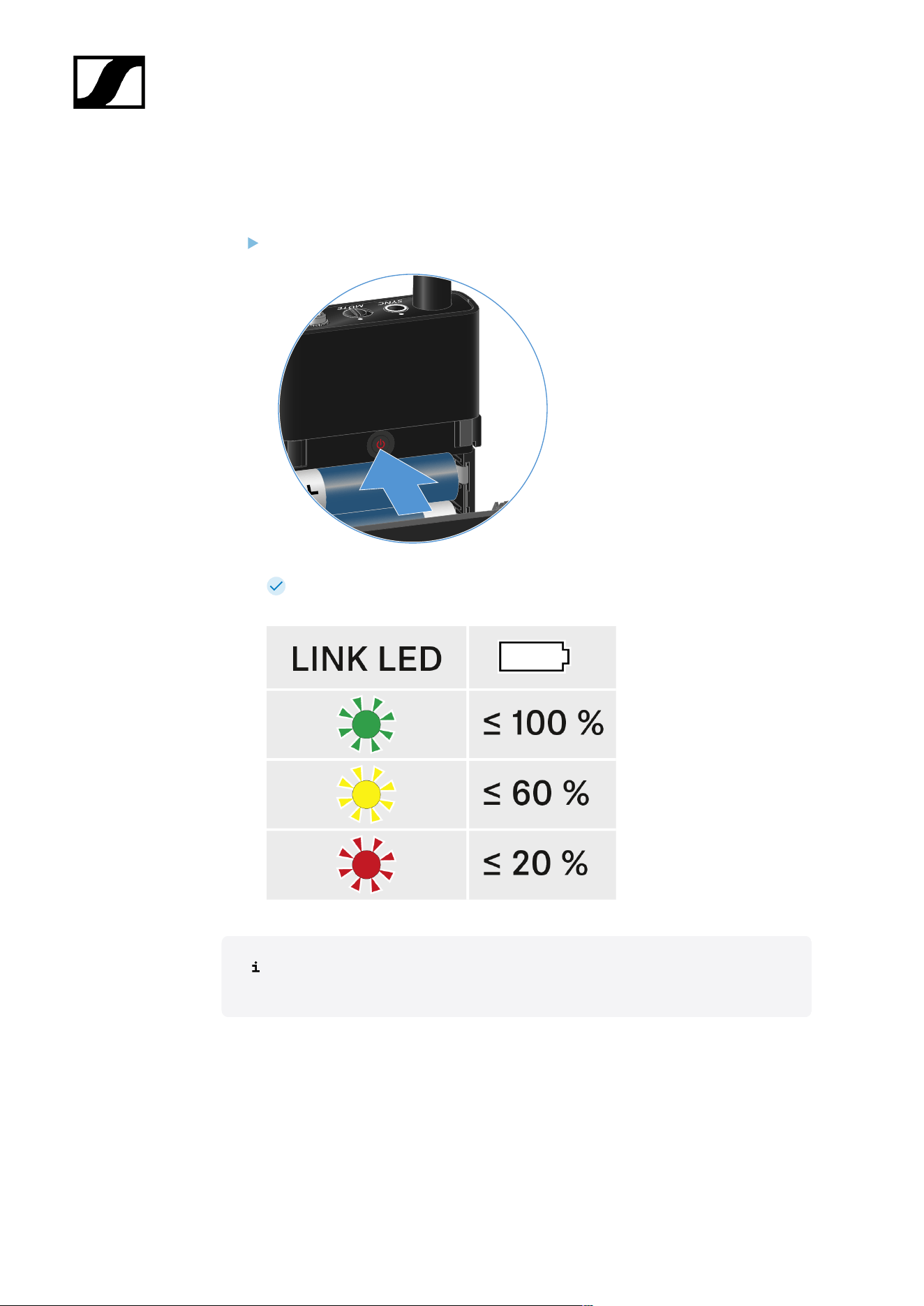
| 3 - Instruction manual
Checking the battery status of the transmitter (Check function)
To check the battery status of the transmitter:
Short-press the ON/OFF button on the transmitter.
The transmitter’s LINK LED flashes to indicate the current charge level of the
battery or the BA 70 rechargeable battery.
Pressing the transmitter’s ON/OFF button will simultaneously trigger the Identify
function: Identifying the paired receiver (Identify function).
129
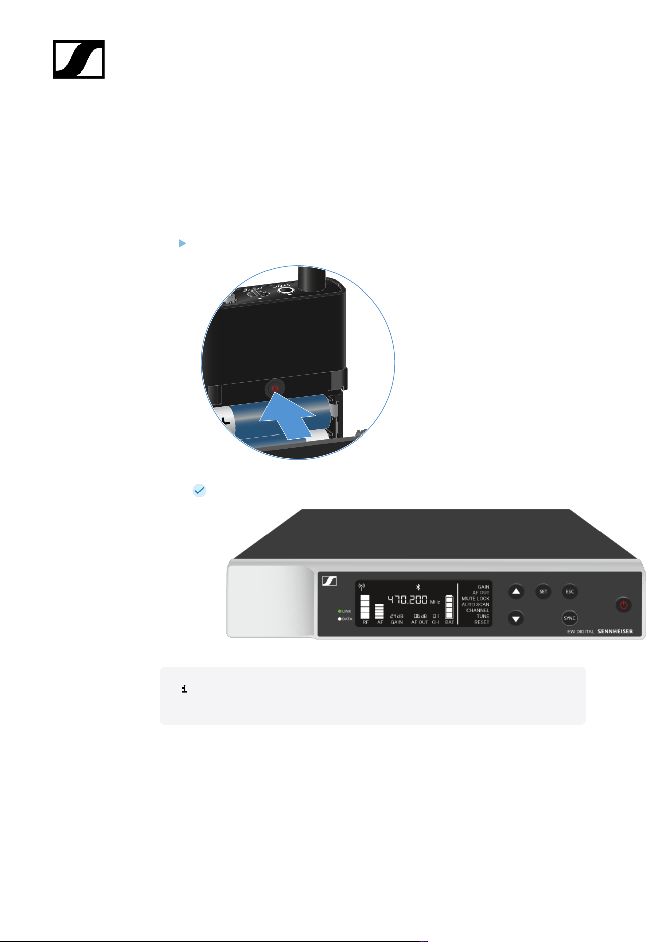
| 3 - Instruction manual
Identifying the paired receiver (Identify function)
In multi-channel systems, you can use the Check function to quickly identify to which
receiver the transmitter is paired.
Both the transmitter and receiver must be switched on.
Short-press the ON/OFF button on the transmitter.
The display on the paired receiver starts flashing.
Pressing the transmitter’s ON/OFF button will simultaneously trigger the Check
function: Checking the battery status of the transmitter (Check function).
130
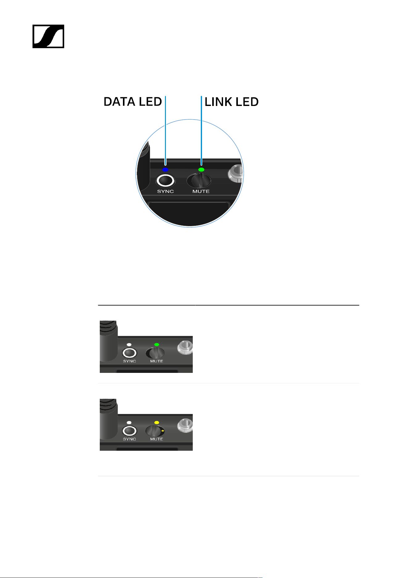
| 3 - Instruction manual
Meaning of the LEDs
The LINK and DATA LEDs on the top of the transmitter can indicate the following information.
LINK LED
The LINK LED provides information about the status of the radio link between the transmitter
and receiver, as well as status information for the paired transmitter.
The LED is green:
• The link between the transmitter and receiver is
established.
• The transmission frequency is active.
The LED is yellow:
• The link between the transmitter and receiver is
established.
• The audio signal is muted.
Or
• No microphone module is mounted on the SKM-S
handheld transmitter.
The LED is flashing yellow:
• The link between the transmitter and receiver is
established.
• The audio signal is overdriven (clipping).
131
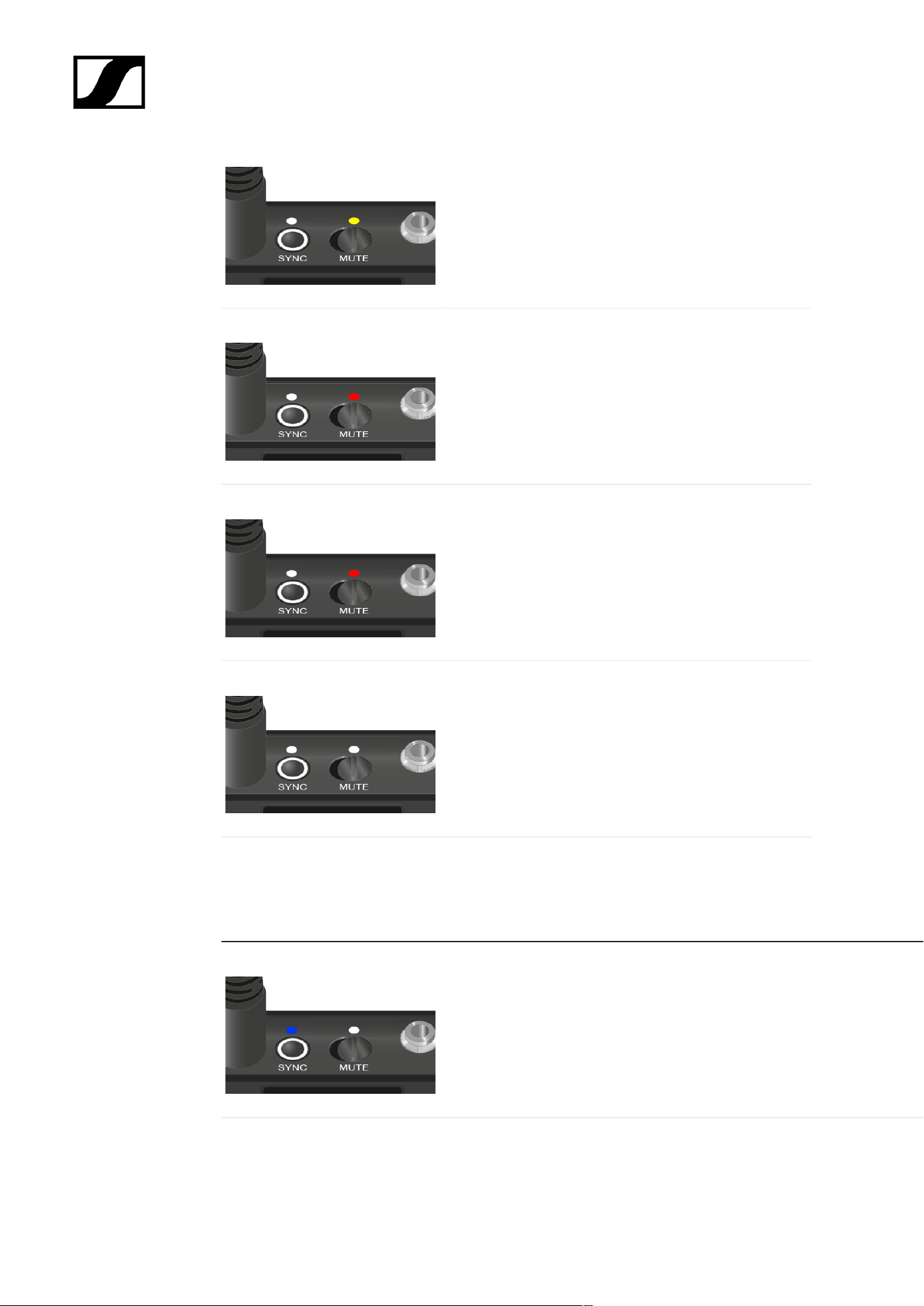
| 3 - Instruction manual
The LED is continuously red:
• The (rechargeable) battery in the transmitter is
dead.
The LED is flashing red:
• The link between the transmitter and receiver is
established.
• The battery/rechargeable battery in the
transmitter is low.
The LED is off:
• No link between the transmitter and receiver.
• The transmitter is switched off.
DATA LED
The DATA LED provides information about the synchronization of transmitters and receivers.
The LED is flashing blue:
• The transmitter is being synchronized with a receiver.
The LED is blue:
• The firmware is being updated.
132
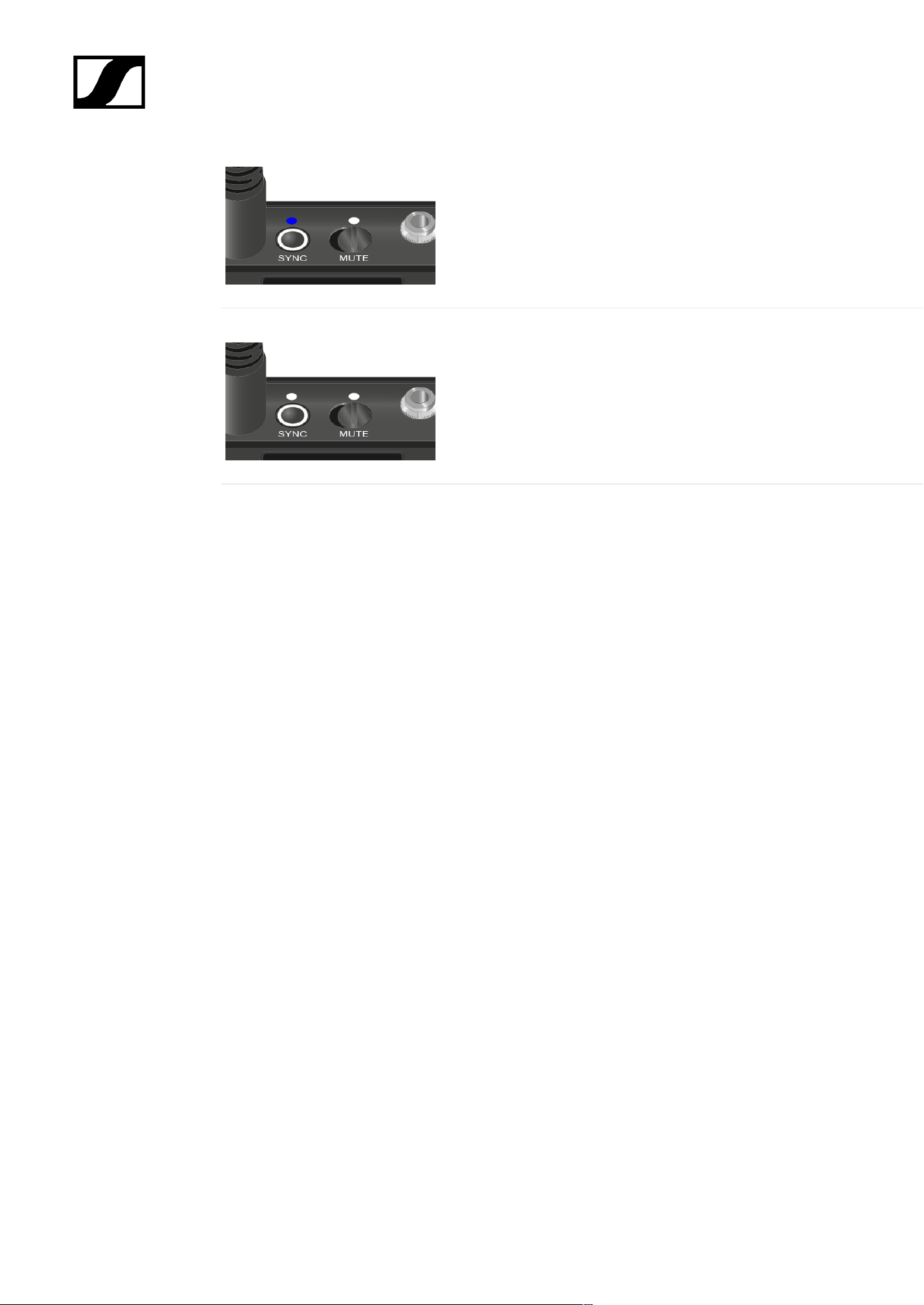
| 3 - Instruction manual
The LED is off:
• There is currently no active data link.
133

| 3 - Instruction manual
Establishing a connection to the receiver
To establish a radio link between the transmitter and the receiver, the devices must be
synchronized.
See Establishing a radio link | Synchronizing the receiver and transmitter
Conditions and restrictions for using frequencies
There may be special conditions and restrictions for using frequencies in your
country.
Before putting the product into operation, find the information for your country
at the following address:
sennheiser.com/sifa
134
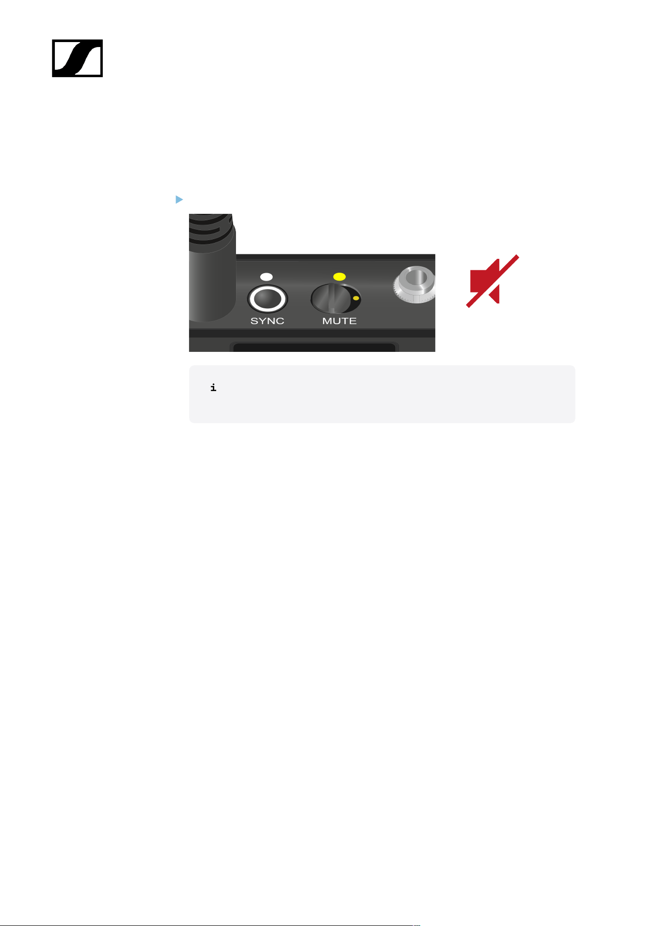
| 3 - Instruction manual
Muting the bodypack transmitter
You can mute the audio signal using the mute switch.
Slide the mute switch to the desired position to mute or activate the audio signal.
You can disable the mute switch by activating the MUTE LOCK option on
the receiver (see MUTE LOCK menu item).
135
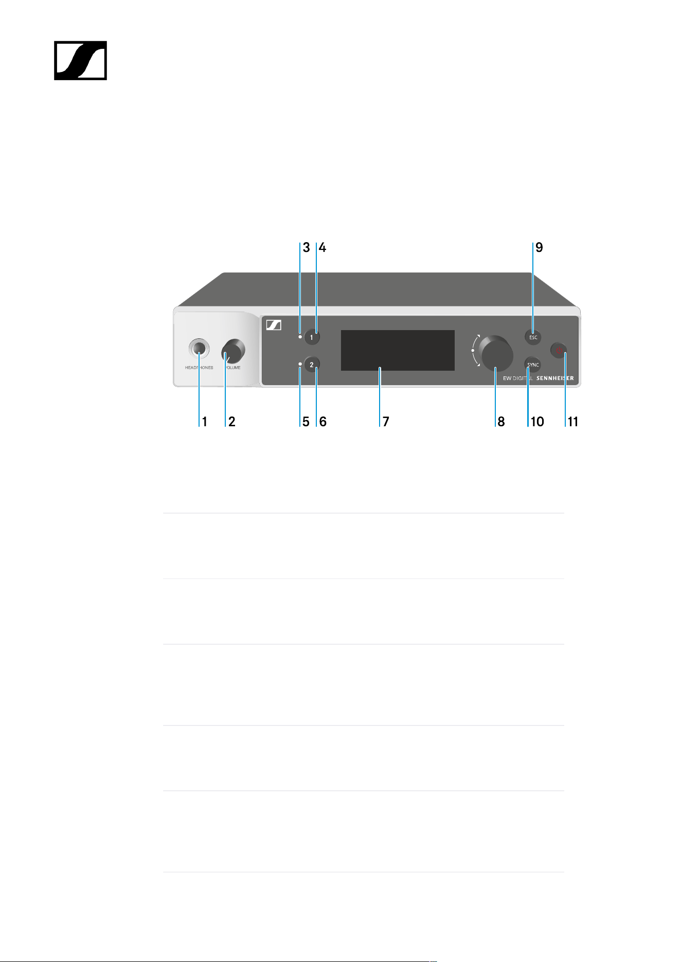
| 3 - Instruction manual
EW-DX EM 2 rack receiver
Product overview
Front
1 Headphone socket
• See Using the headphone output
2 Volume control for the headphone socket
• See Using the headphone output
3 CH 1 LED to indicate the status of channel 1
• See Meaning of the LEDs
4 CH 1 button for selecting channel 1
• See Displays on the receiver’s display panel
• See Buttons for navigating the menu
5 CH 2 LED to indicate the status of channel 2
• See Meaning of the LEDs
6 CH 2 button for selecting channel 2
• See Displays on the receiver’s display panel
• See Buttons for navigating the menu
136

| 3 - Instruction manual
7 Display for status information and operating menu
• See Displays on the receiver’s display panel
8 Jog dial (UP/DOWN/SET) for navigating the operating menu
• See Buttons for navigating the menu
9 ESC button for canceling an action in the menu
• See Buttons for navigating the menu
10 SYNC button for synchronizing the transmitter and receiver
• See Establishing a radio link | Synchronizing the receiver and
transmitter
11 ON/OFF button for switching the device on and off
• See Switching the receiver on and off
Back
1 PoE/Ethernet RJ-45 socket for controlling the device over the network and for Power
over Ethernet power supply
• See Connecting receivers in a network
• See Connecting/disconnecting the receiver to/from the power supply system
2 6.3 mm jack socket for AF out Unbalanced audio output for channel 1
• See Outputting audio signals
137

| 3 - Instruction manual
3 6.3 mm jack socket for AF out Unbalanced audio output for channel 2
• See Outputting audio signals
4 XLR-3 socket for AF out Balanced audio output for channel 2
• See Outputting audio signals
5 XLR-3 socket for AF out Balanced audio output for channel 1
• See Outputting audio signals
6 BNC sockets ANT 1 RF in and ANT 2 RF in for antenna inputs
• See Connecting antennas
7 Strain relief for the connection cable of the power supply unit
• See Connecting/disconnecting the receiver to/from the power supply system
8 DC in connection socket for the power supply unit
• See Connecting/disconnecting the receiver to/from the power supply system
138

| 3 - Instruction manual
Connecting/disconnecting the receiver to/from the power supply
system
You can operate the receiver using either the included power supply unit or with Power over
Ethernet (PoE IEEE 802.3af Class 0). Please refer to the following information.
Power from the power supply unit
If using a power supply unit, use only the power supply unit included with the
device. It is designed for your receiver and ensures safe operation.
You will find the power supply unit and the country adapters in the packaging
under the tray:
To connect the receiver to the power supply system:
Insert the plug of the power supply unit into the DC in socket on the receiver.
Pass the cable of the power supply unit through the strain relief.
Slide the supplied country adapter onto the power supply unit.
139

| 3 - Instruction manual
Plug the power supply unit into the wall socket.
To completely disconnect the receiver from the power supply system:
Unplug the power supply unit from the wall socket.
Unplug the power supply unit from the DC in socket on the receiver.
140
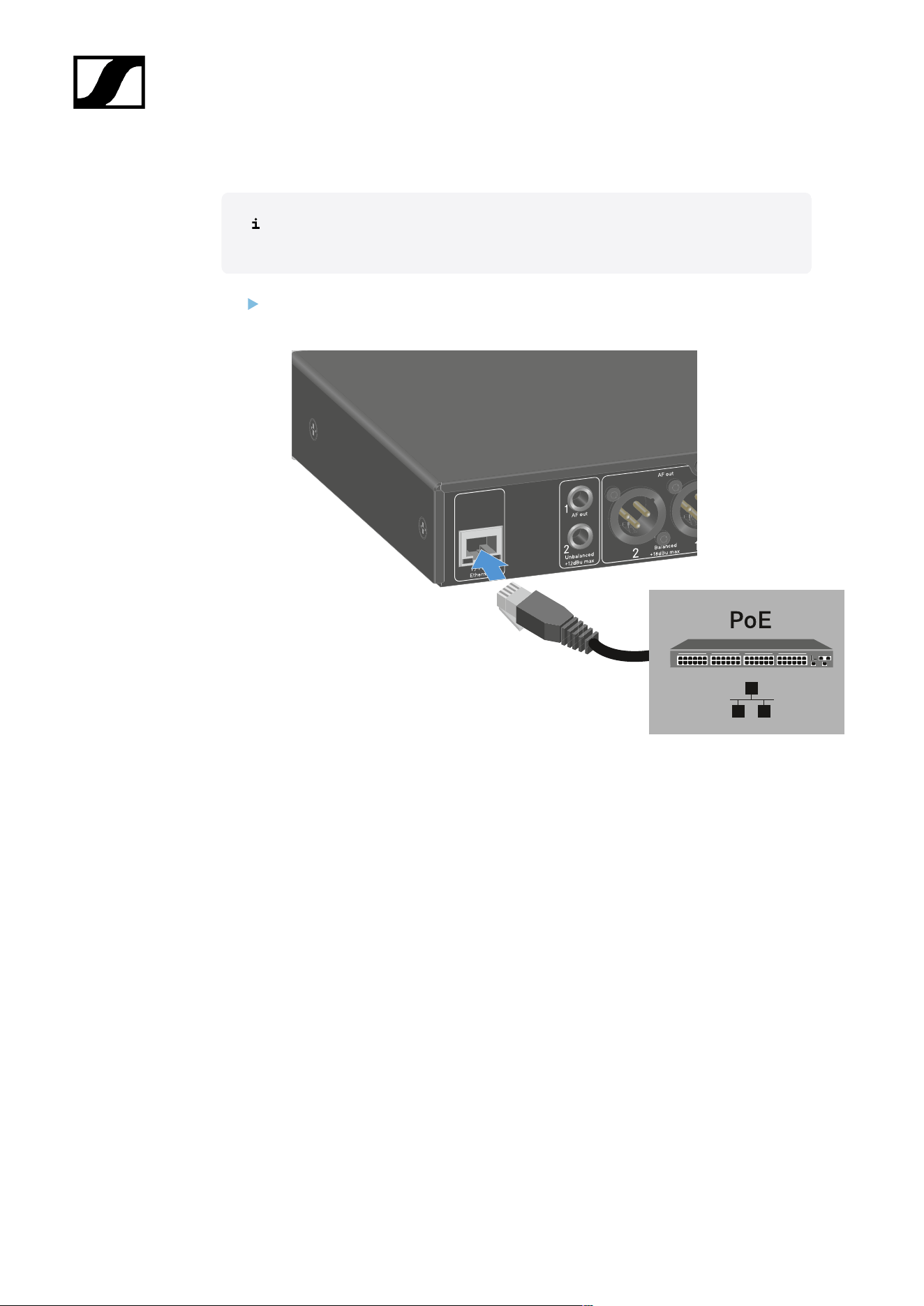
| 3 - Instruction manual
Power over Ethernet (PoE)
The receiver can be powered via Power over Ethernet (PoE IEEE 802.3af Class
0).
Connect the receiver to a PoE-enabled network switch.
141
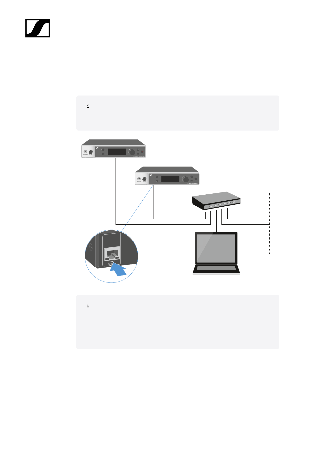
| 3 - Instruction manual
Connecting receivers in a network
You can monitor and control one or more receivers via a network connection using the
Sennheiser Wireless Systems Manager (WSM) or Sennheiser Control Cockpit (SCC)
software.
The network does not have to be a homogeneous network including only
receivers. You can integrate the receiver into your existing network infrastructure
with any other types of devices.
For more information about controlling devices via the Sennheiser Wireless
Systems Manager or Sennheiser Control Cockpit software, refer to the
instruction manual for the software. You can download the software here:
sennheiser.com/wsm
sennheiser.com/scc
142
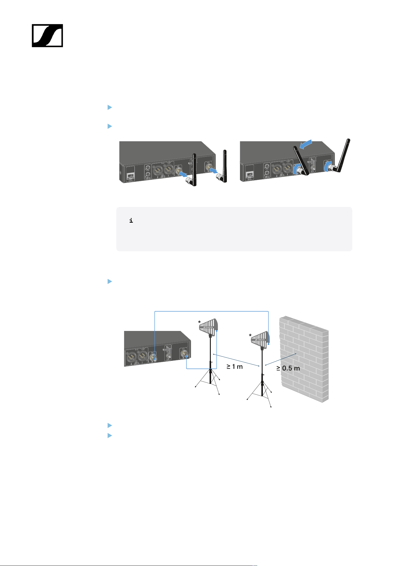
| 3 - Instruction manual
Connecting antennas
To connect the supplied rod antennas:
Connect the antennas to the two antenna inputs on the receiver as shown in the
figure.
Slightly angle the antennas to the left and right as shown in the figure.
If you are using more than one receiver, we recommend using remote
antennas and possibly the EW-D ASA antenna splitter (EW-D ASA
antenna splitter).
To connect remote antennas:
Connect the antennas to the two antenna inputs on the receiver as shown in the
figure.
Observe the specified minimum spacing.
Observe the specified minimum spacing to the transmitters.
143
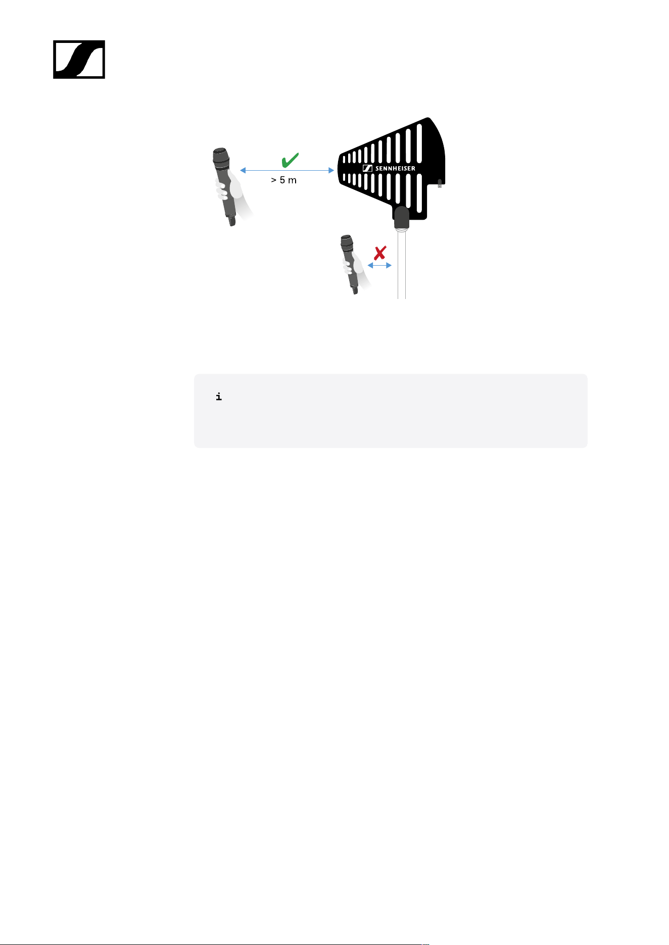
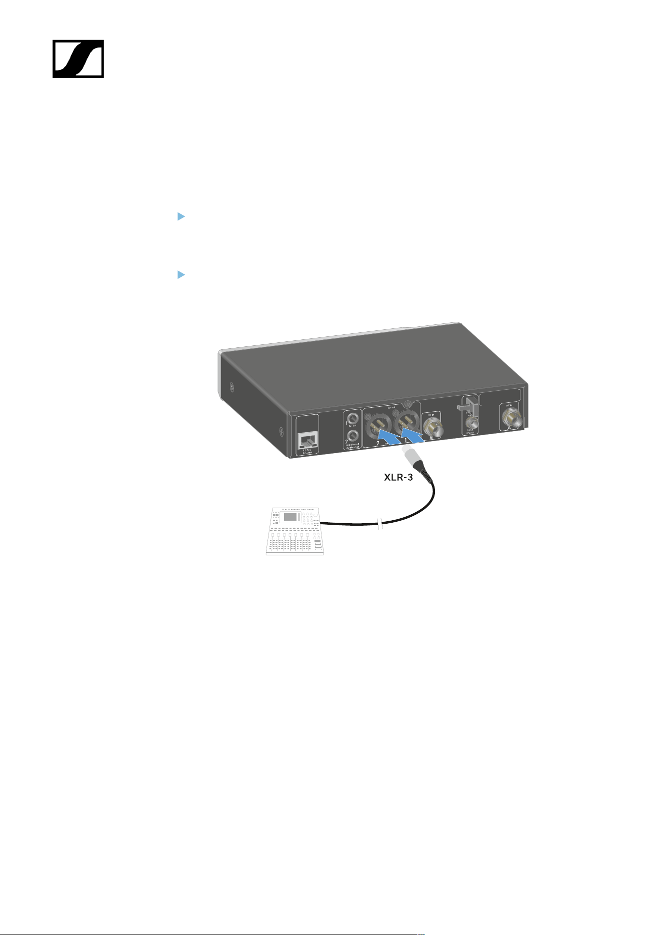
| 3 - Instruction manual
Outputting audio signals
Each of the two channels on the EW-DX EM 2 has both a balanced XLR-3M output socket
and an unbalanced 6.3 mm (1/4") jack output socket.
Always use only one of the two output sockets for each channel.
To connect an XLR cable:
Plug the XLR cable into the AF out Balanced socket for the respective channel on the
EW-DX EM 2.
145
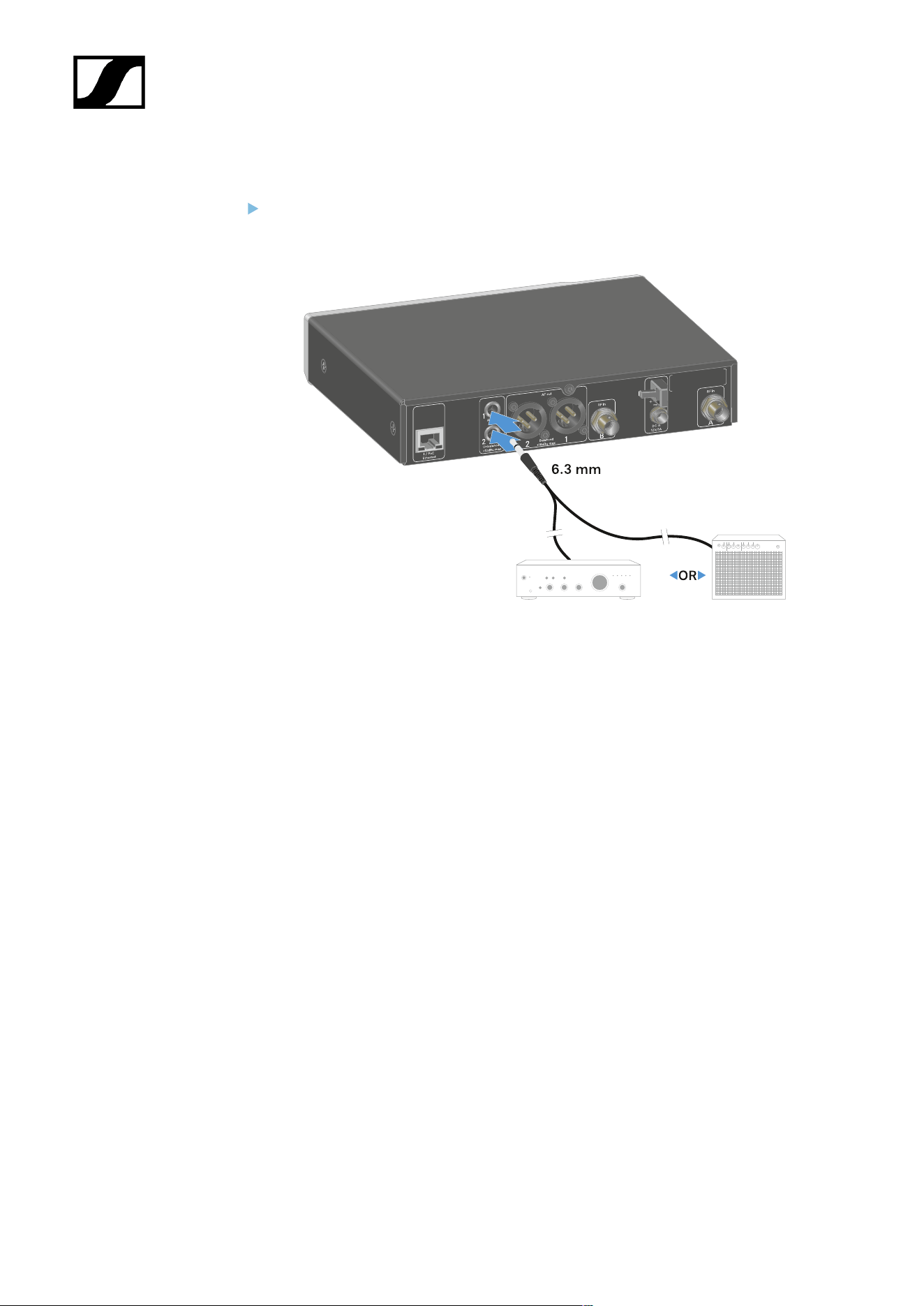
| 3 - Instruction manual
To connect a jack cable:
Plug the jack cable into the AF out Unbalanced socket for the respective channel on
the EW-DX EM 2.
146

| 3 - Instruction manual
Installing receivers in a rack
Observe the following instructions when mounting the receiver in a rack.
The mounting brackets for installing the receiver in the rack can be found in the
packaging under the tray:
NOTICE
Rack mounting poses risks!
When installing the device in a closed 19" rack or multi-rack assembly,
please consider that, during operation, the ambient temperature, the
mechanical load and the electrical potentials will be different from those
of devices which are not mounted into a rack.
Make sure that the ambient temperature within the rack does
not exceed the permissible temperature limit stated in the
specifications. See Specifications.
Ensure sufficient ventilation; if necessary, provide additional
ventilation.
Make sure that the mechanical load of the rack is even.
When connecting to the power supply system, observe the
information indicated on the type plate. Avoid overloading the
circuits. If necessary, provide overcurrent protection.
When mounting in a rack, please note that intrinsically harmless
leakage currents of the individual power supply units may
accumulate, thereby exceeding the permissible limit value. As a
remedy, ground the rack via an additional ground connection.
147
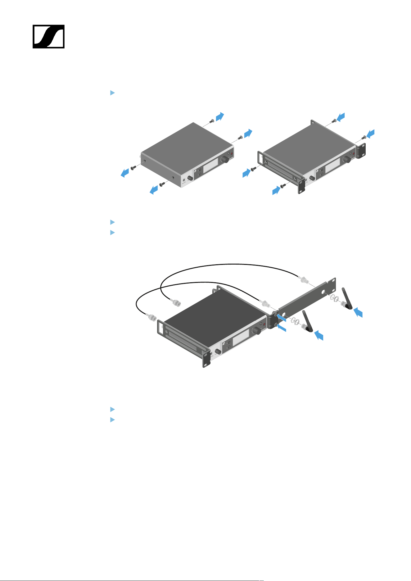
| 3 - Instruction manual
Mounting a single receiver in a rack
Connect the mounting brackets to the sides of the receiver as shown.
Attach the front panel as shown.
If desired, attach the antennas to the front panel as shown. This requires the optional
AM 2 antenna front mount kit (see Accessories for rack mounting).
Mounting two receivers side by side in a rack
Place both receivers upside down and side by side on an even surface.
Tighten the jointing plate as shown.
148

| 3 - Instruction manual
Attach the mounting brackets as shown.
149
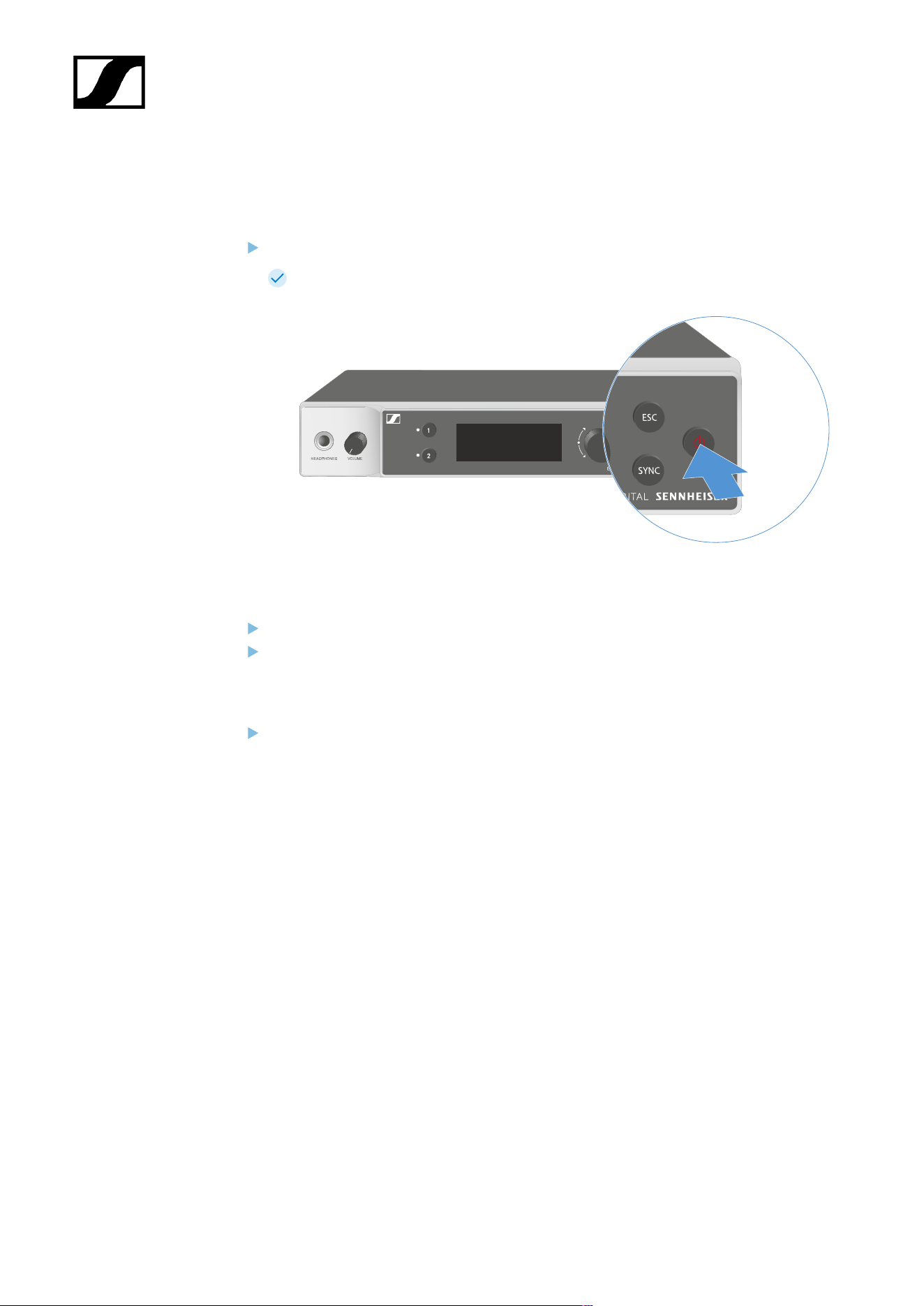
| 3 - Instruction manual
Switching the receiver on and off
To switch the receiver on:
Short-press the ON/OFF button.
The receiver switches on.
To switch the receiver to standby mode:
If necessary, deactivate the lock-off function (see Lock-off function).
Hold down the ON/OFF button until the display switches off.
To switch the receiver off completely:
Disconnect the receiver from the power supply system by unplugging the power
supply unit from the wall socket or disconnecting the PoE connection.
150
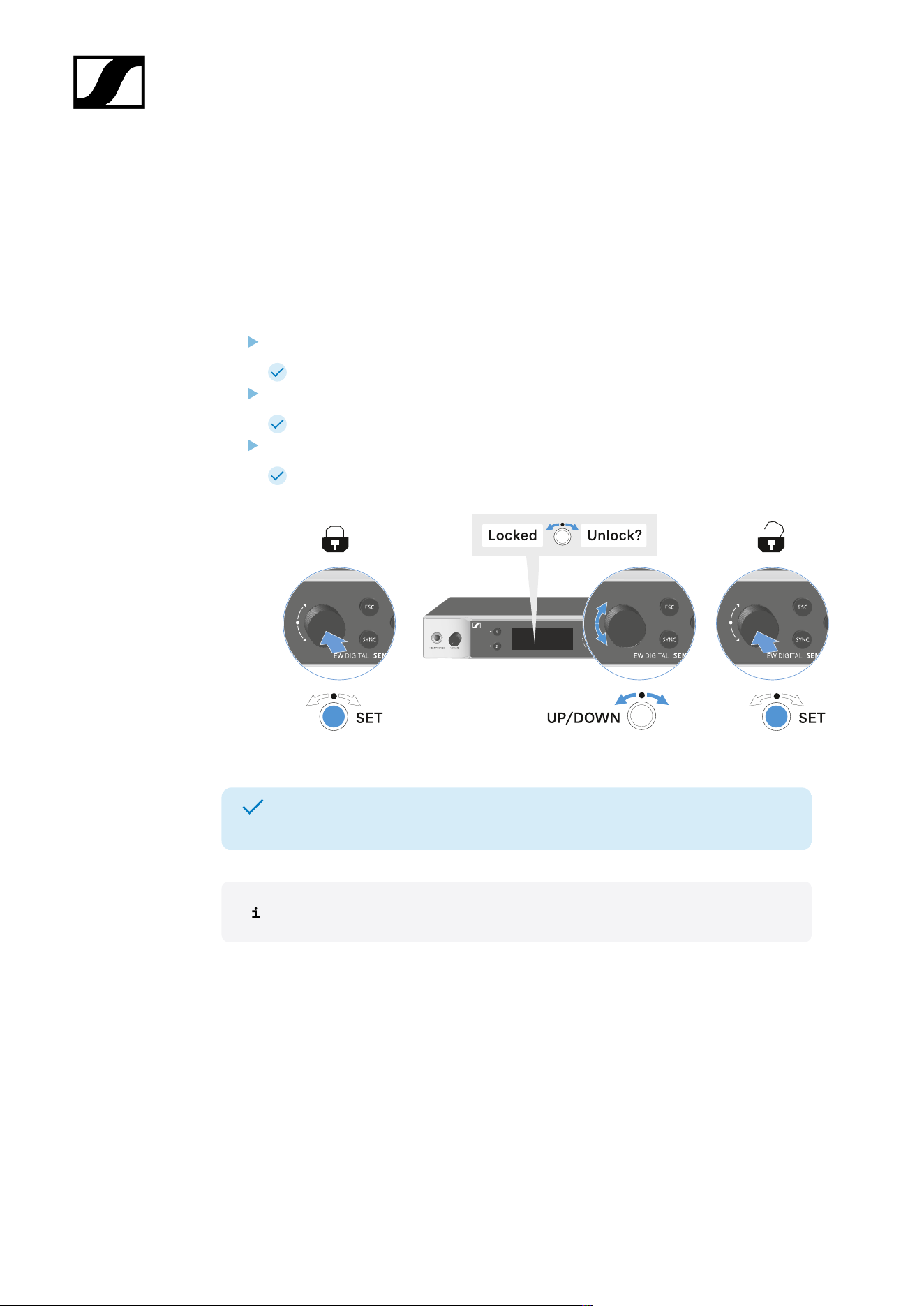
| 3 - Instruction manual
Lock-off function
You can enable or disable the automatic lock-off function in the This Device -> Device Lock
menu item (see System -> This Device menu item).
To temporarily deactivate the lock-off function:
Press the jog dial.
Locked appears in the display panel.
Turn the jog dial.
Unlock? appears in the display panel.
Press the jog dial.
Lock-off function is now temporarily deactivated.
The lock-off function remains deactivated while you are actively working in the
operating menu.
After 10 seconds of inactivity, it automatically activates again.
151

| 3 - Instruction manual
Using the headphone output
You can use the headphone output on the front of the receiver (6.3 mm jack) to listen to the
audio signals of the two channels.
CAUTION
Danger due to high volume levels
Volume levels that are too high may damage your hearing.
Turn down the volume of the headphone output before you put on
the headphone.
Connect the headphone to the headphone output.
Press the CH 1 or CH 2 button to listen to the audio signal from channel 1 or channel 2.
The headphone icon on the display indicates which channel is currently active
on the headphone output. By default, the signal from channel 1 is active on the
headphone output.
You can control the volume by turning the volume knob next to the headphone output.
152
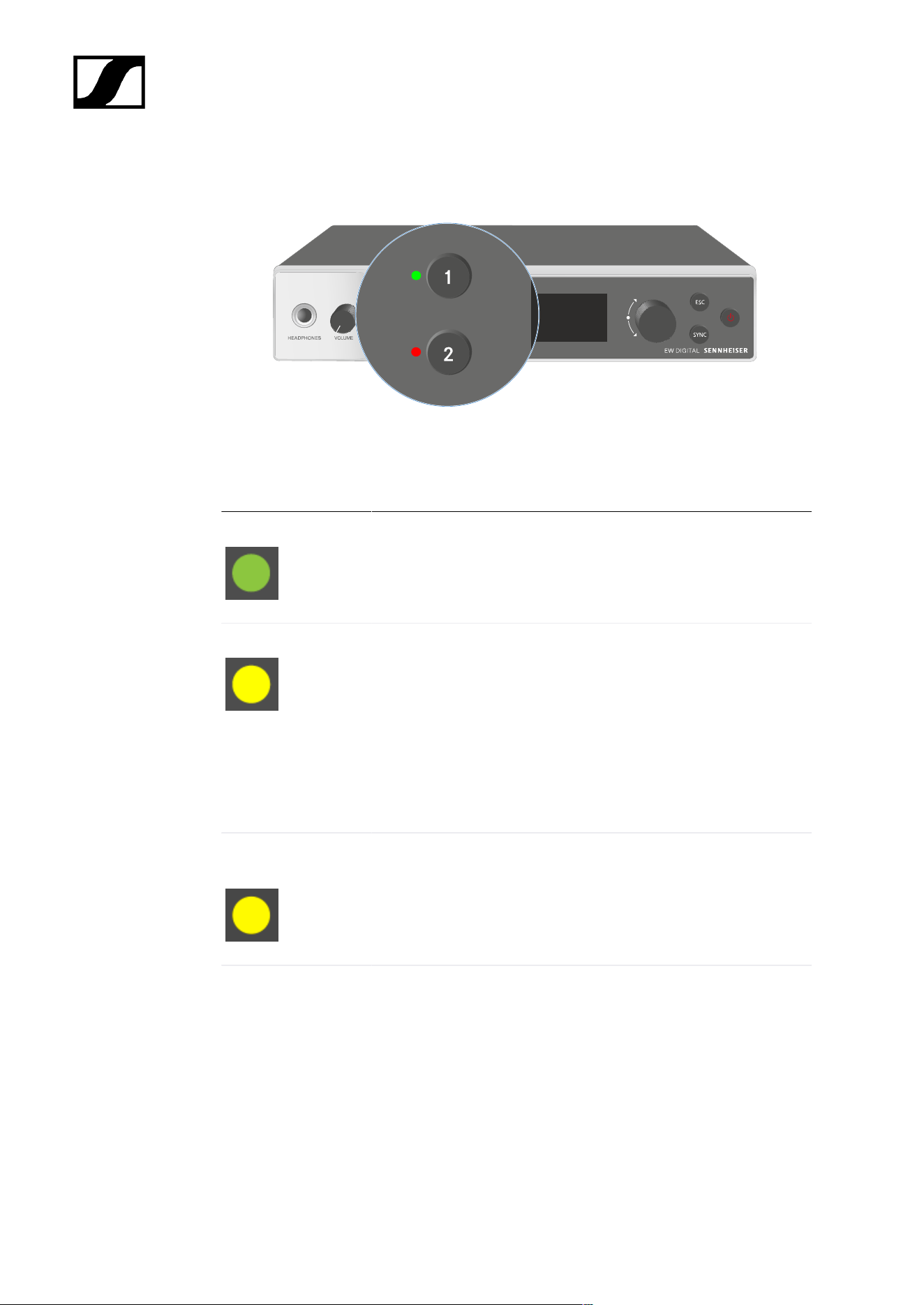
| 3 - Instruction manual
Meaning of the LEDs
The two LEDs on the front of the receiver indicate the following information for channel 1 and
channel 2.
The LED is green:
• The link between the transmitter and receiving channel is
established.
• The audio signal is active.
The LED is yellow:
• The link between the transmitter and receiving channel is
established.
• The audio signal is muted.
or
• No microphone module is mounted on the handheld
transmitter.
The LED is flashing
yellow:
• The link between the transmitter and receiving channel is
established.
• The audio signal is overdriven (clipping).
The LED is
continuously red:
• The link between the transmitter and receiving channel is
established.
• The audio signal is overdriven (clipping).
153

| 3 - Instruction manual
The LED is flashing
red:
• The link between the transmitter and receiving channel is
established.
• The battery/rechargeable battery in the paired transmitter is
low.
The LED is flashing
blue:
• The Bluetooth Low Energy link is being established
between the receiver and a smartphone or tablet with the
Smart Assist app.
or
• The receiving channel is being synchronized with a
transmitter.
The LED is blue:
• The firmware is being updated.
154

| 3 - Instruction manual
Displays on the receiver’s display panel
Status information such as frequency, reception quality, battery status and audio level is
shown on the display.
The display also shows the operating menu, which you can use to configure all of the settings
(see Buttons for navigating the menu).
Home screen
The home screen is the default view on the display. The following information for both
receiving channels is displayed here.
Antenna switching diversity:
Indicates which of the two antennas is currently active (left or right).
Signal level:
Displays the RF signal strength for the respective channel.
Link quality:
Displays the transmission quality for the respective channel.
155

| 3 - Instruction manual
On the one hand, the transmission quality depends on the field strength (RF
level indicator on the display). However, on the other hand, it also depends on
external sources of interference that cannot be identified on the RF level indicator
(for example, they may be on the same frequency or a very close neighboring
frequency or may not affect the field strength).
As a basic principle, a value significantly higher than 50% should be achieved
for a secure transmission.
Link name:
You can assign a name to the radio link in the receiver menu (see Ch 1 / Ch 2 -> Name menu
item).
Frequency:
You can set the frequency of the radio link manually or using the Auto-Setup function.
• See Ch 1 / Ch 2 -> Frequency menu item
• See Ch 1 / Ch 2 -> Scan / Auto Setup menu item
Transmitter audio level:
Displays the audio input level for the respective channel (see Ch 1 / Ch 2 -> Gain menu item).
This level is separate from the audio level that is output from the receiver (see Ch 1 / Ch 2 ->
AF Out menu item).
Transmitter battery:
Indicates the charging status of the transmitter’s BA 70 rechargeable battery or batteries.
When using the BA 70 rechargeable battery, the remaining runtime is also displayed in hours
and minutes.
Mute mode:
The mute switch is deactivated on the received transmitter.
The mute switch on the received transmitter is set to AF Mute and the audio
signal is muted.
• EW-DX SKM-S: Configuring mute mode and muting the handheld
transmitter (EW-DX SKM-S only)
• EW-DX SK: Configuring mute mode and muting the bodypack transmitter
Headphones:
156

| 3 - Instruction manual
The headphones icon indicates which channel is currently active on the
headphone output (see Using the headphone output).
Sync state:
This icon indicates that different values are set for the receiving channel of the
receiver and the transmitter. These values can be synchronized (see Connecting
to the EW-DX EM receivers / synchronizing the EW-DX EM).
System icons:
The LD icon is displayed when Link Density mode is activated. See System -> Link
Density menu item.
The lock icon is displayed when the Auto Lock function is enabled. See Lock-off
function.
The network icon appears when a network connection is successfully established.
See Connecting receivers in a network.
The shield icon is displayed when AES 256 encryption is enabled. See System ->
Link Encryption menu item.
Home screens 2 and 3
Turn the jog dial on the home screen to the right.
The second home screen appears with network information for the device.
Turn the jog dial to the right again.
The third home screen appears with information about the software and
hardware.
157
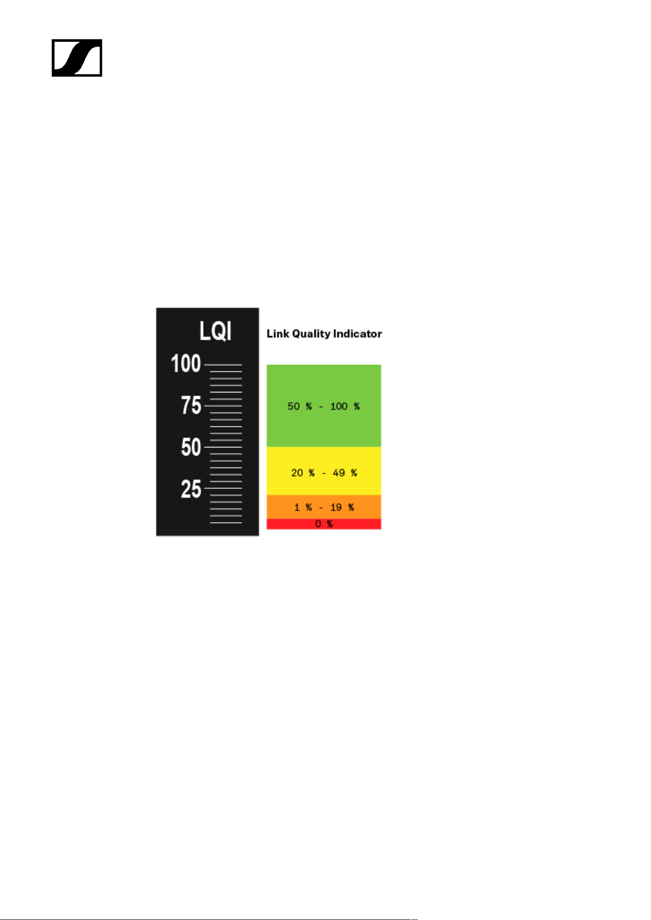
| 3 - Instruction manual
Meaning of the Link Quality Indicator
The LQI (Link Quality Indicator) on the display of the receiver shows the transmission
quality for the respective channel.
On the one hand, the transmission quality depends on the field strength (RF indicator on the
receiving channel display). However, on the other hand, it also depends on external sources
of interference that cannot be identified on the RF indicator (for example, they may be on the
same frequency or a very close neighboring frequency or may not affect the RF strength).
As a basic principle, an LQI value significantly higher than 50% should be achieved for a
secure transmission.
The LQI display shows the following information:
Green range from 50% to 100%:
• No transmission errors
The transmission quality is good enough to ensure an audio quality of 100%.
Yellow range from 20% to 49%:
• Individual transmission errors: short-term error correction active
• Individual audio artifacts may be audible
There are initial transmission errors. In rare cases, there are initial audible audio artifacts.
Error correction may be active in this case.
158

| 3 - Instruction manual
Orange range from 1% to 19%:
• Frequent transmission errors: long-term error correction active
• Risk of audio drop-outs
The transmission errors increase, which means that the error correction duration also
increases. There is a risk of audio drop-outs.
Red range 0%:
• No transmission
In this range, the transmission quality is so poor that audio drop-outs can no longer be
avoided.
159
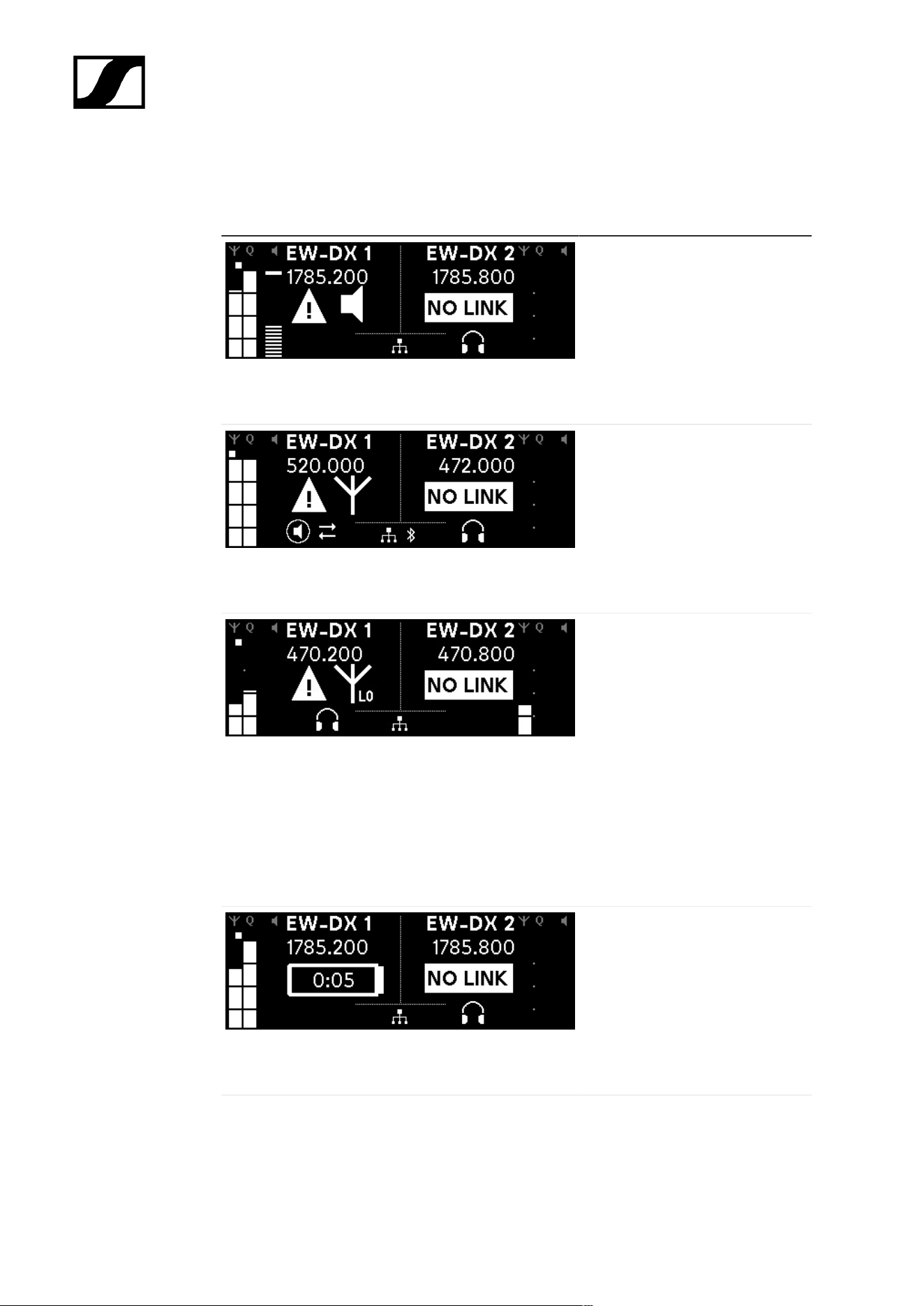
| 3 - Instruction manual
Status messages
In certain situations, status messages may appear on the display.
AF Peak
The device is experiencing
repeated or prolonged audio
overload.
• Check the input signal on
the transmitter and adjust
it.
RF Peak
The antenna signal is
overmodulated.
• Increase the distance
between the receiving
antenna and the
transmitter.
Low Signal
The received signal is too low
or the transmission quality is
insufficient.
• Check that the antenna is
properly connected and
inspect the system wiring.
• Check that the transmitter
is within the reception
range.
• Check the orientation of the
receiver’s antenna.
Low Battery
The transmitter’s batteries or
rechargeable battery pack have
little battery life remaining (less
than 30 minutes).
• Replace the rechargeable
battery or batteries.
160

| 3 - Instruction manual
NoLink
No link to a transmitter.
• Verify that the transmitter is
on and within range.
• Check whether the
transmitter is muted (“RF
Mute” setting).
161

| 3 - Instruction manual
Channel 1
On the receiver’s home screen, press the CH 1 button.
The home screen for channel 1 appears.
In addition to the status information displayed on the home screen, information about
the channel’s audio settings is also displayed.
Turn the jog dial to the right to view more information about the received transmitter.
Turn the jog dial further to the right to mute or unmute the channel’s audio signal.
162

| 3 - Instruction manual
Press the jog dial to confirm your selection.
163


| 3 - Instruction manual
Buttons for navigating the menu
Use the following buttons to navigate through the receiver’s operating menu.
Press the jog dial
• Jumps from the home screen to the operating menu
• Calls up a menu item
• Changes to a submenu
• Saves settings
Turn the jog dial
• Selects a standard display (see Displays on the
receiver’s display panel)
• Changes to the previous or next menu item
• Changes the setting of a menu item
Press the ESC button
• Cancels the entry and returns to the previous display
Opening the menu and navigating the menu items
165
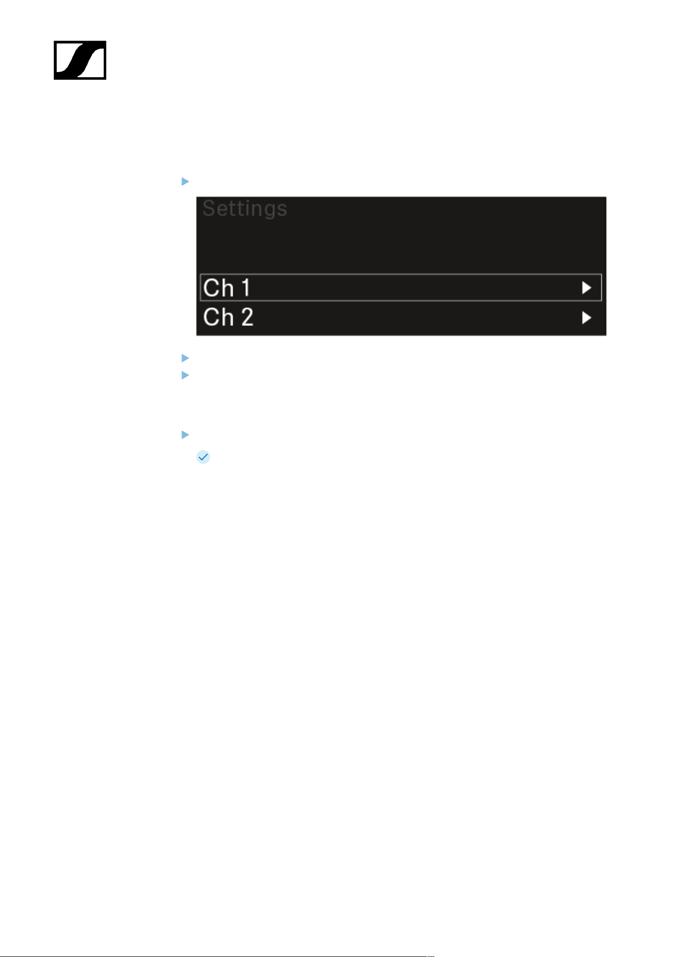
| 3 - Instruction manual
Opening the menu and navigating the menu items
To open the menu:
Press the jog dial when you are on the home screen.
Turn the jog dial to navigate to your desired menu item.
Press the jog dial to open the selected menu item.
To exit the menu:
Press the ESC button to exit the menu and return to the home screen.
Changes that were not previously saved by pressing the jog dial will be lost.
166
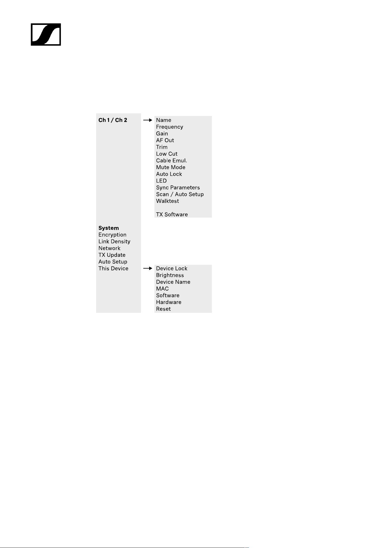
| 3 - Instruction manual
Menu structure
The figure shows the complete menu structure in an overview.
Version: firmware 3.0.0
167

| 3 - Instruction manual
Setting options in the menu
In the receiver menu, you can configure the following settings.
Changing the name of the radio link
• Ch 1 / Ch 2 -> Name menu item
Adjusting frequencies
• Ch 1 / Ch 2 -> Frequency menu item
Adjusting the gain of the wireless link
• Ch 1 / Ch 2 -> Gain menu item
Setting the output level of the audio signal
• Ch 1 / Ch 2 -> AF Out menu item
Adjusting the trim of the connected transmitter
• Ch 1 / Ch 2 -> Trim menu item
Adjusting the low-cut filter
• Ch 1 / Ch 2 -> Low Cut menu item
Configuring cable emulation for the bodypack transmitter
• Ch 1 / Ch 2 -> Cable Emul. menu item
Setting the function of the transmitter’s mute switch
• Ch 1 / Ch 2 -> Mute Mode menu item
Enabling the transmitter’s automatic lock-off function
• Ch 1 / Ch 2 -> Auto Lock menu item
Configuring the behavior of the transmitter’s LEDs
• Ch 1 / Ch 2 -> LED menu item
Activating/deactivating the parameters to be synchronized on the transmitters
• Ch 1 / Ch 2 -> Sync Parameters menu item
Performing a frequency scan and automatic frequency setup
• Ch 1 / Ch 2 -> Scan / Auto Setup menu item
168
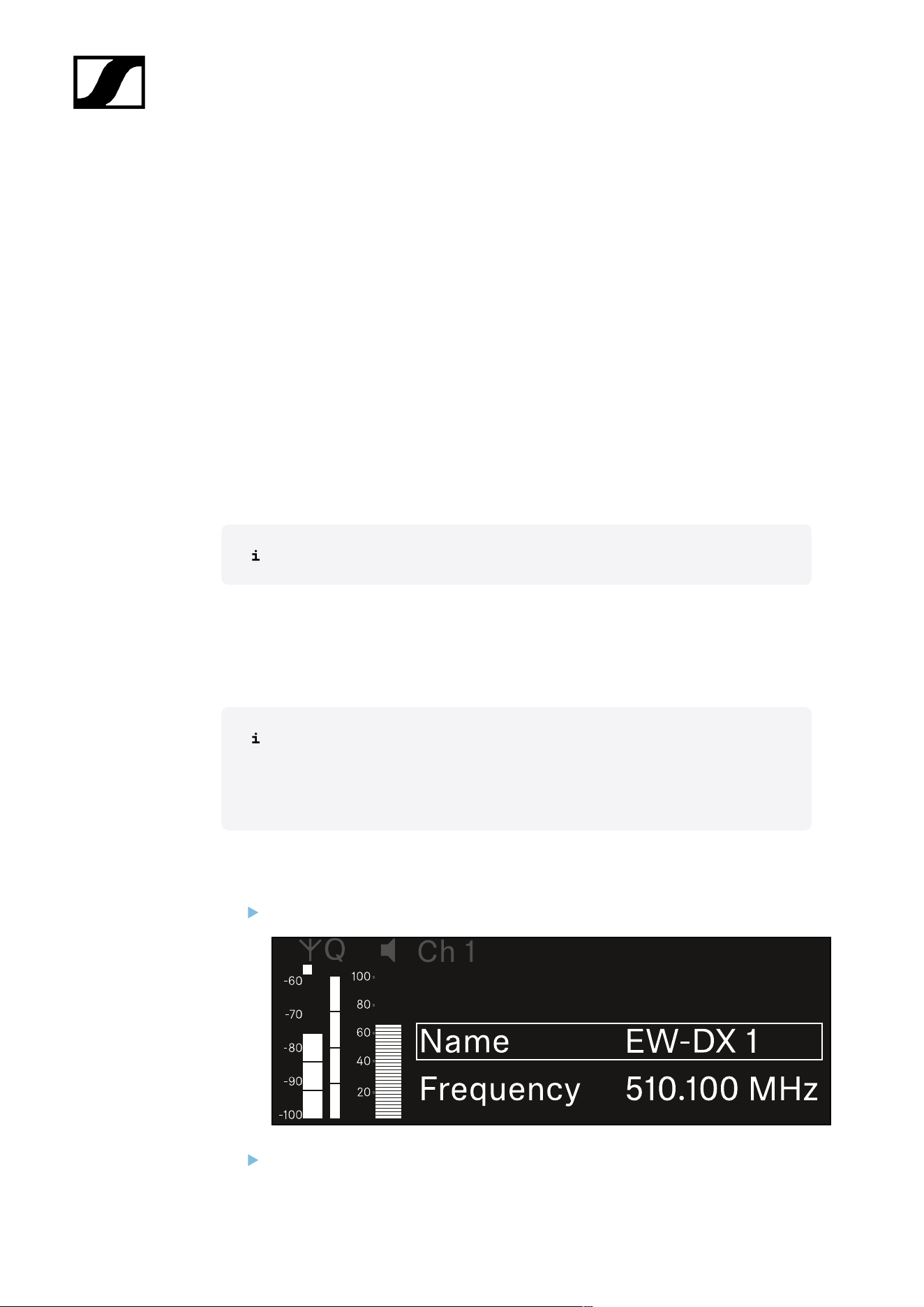
| 3 - Instruction manual
check the reception quality within the operating environment
• Ch 1 / Ch 2 -> Walktest menu item
Viewing the software version of the connected transmitters
• Ch 1 / Ch 2 -> TX Software menu item
Configuring different system settings
• Enabling AES 256 encryption
• Setting transmission mode
• Configuring network settings
• Updating the firmware for the transmitters
• Activating the Auto Setup function
• Changing device names
• System menu item
You can find an overview of the entire menu structure under Menu structure.
Ch 1 / Ch 2 -> Name menu item
In the Name menu item, you can define the name of the link for the channel in question.
This name is the name of the radio link between the transmitter and receiving
channel. You can set the name of the receiver as it will appear in a network from
the This Device menu in the system menu. See System -> This Device menu
item.
To open the Name menu item:
In the menu, navigate to the Name menu item for the desired channel.
Press the jog dial to open the menu.
169

| 3 - Instruction manual
The following view is displayed:
To enter the desired link name:
Turn the jog dial to select the desired character.
Press the jog dial to go to the next position.
At the last position, press the jog dial to save the selected name.
Or
Press the ESC button to cancel the entry without saving the settings.
For the chosen link name to appear on the display of the received transmitter,
you must synchronize the channel (Connecting to the EW-DX EM receivers /
synchronizing the EW-DX EM).
170

| 3 - Instruction manual
Ch 1 / Ch 2 -> Frequency menu item
In the Frequency menu item, you can adjust the frequency for the channel in question.
You can select a frequency from the predefined list or set the frequency manually.
To open the Frequency menu item:
In the menu, navigate to the Frequency menu item for the desired channel.
Press the jog dial to open the menu.
The following view is displayed:
Rotate the jog dial to select between the List and Frequency subitems.
The List subitem allows you to select a frequency from the predefined list. The
Frequency subitem lets you set the desired frequency manually.
171
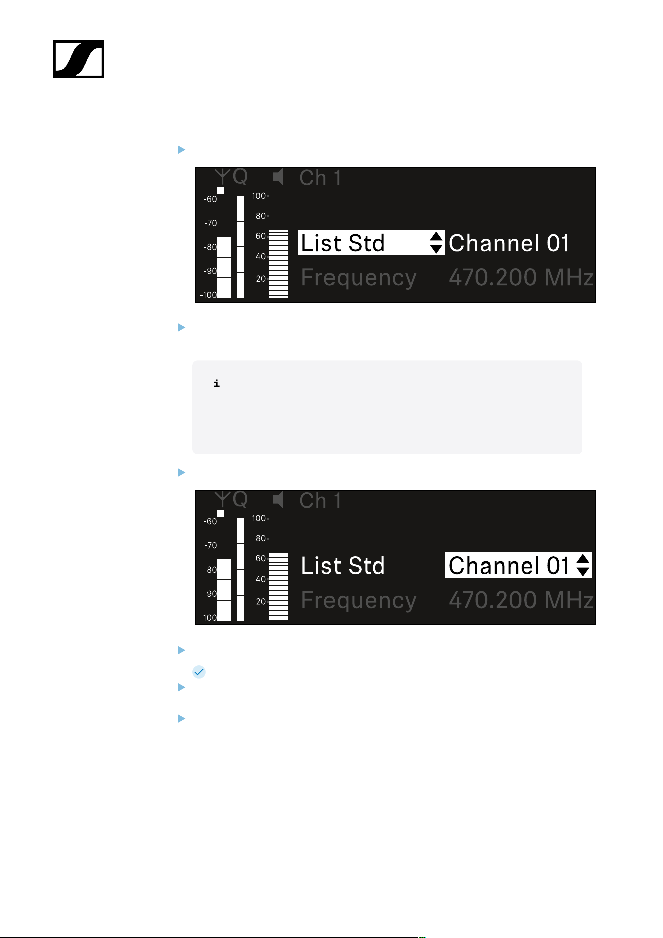
| 3 - Instruction manual
To select a frequency from a predefined list:
Open the List subitem.
Rotate the jog dial to choose between the predefined list (List Std) and the user-
defined list (List Usr).
You can create a custom list using the Wireless Systems Manager
(WSM) software and upload it to the receiver. For more information on
the WSM software, see:
sennheiser.com/wsm
Press the jog dial to confirm your selection.
Rotate the jog dial to select the desired channel from the list.
The frequency assigned to the channel is displayed.
Press the jog dial to save the selected channel.
Or
Press the ESC button to cancel the entry without saving the settings.
172

| 3 - Instruction manual
To set the frequency manually:
Open the Frequency subitem.
Turn the jog dial to set the MHz range for the frequency.
Press the jog dial to confirm your selection.
Turn the jog dial to set the kHz range for the frequency.
Press the jog dial to save your selected frequency.or
Or
Press the ESC button to cancel the entry without saving the settings.
173
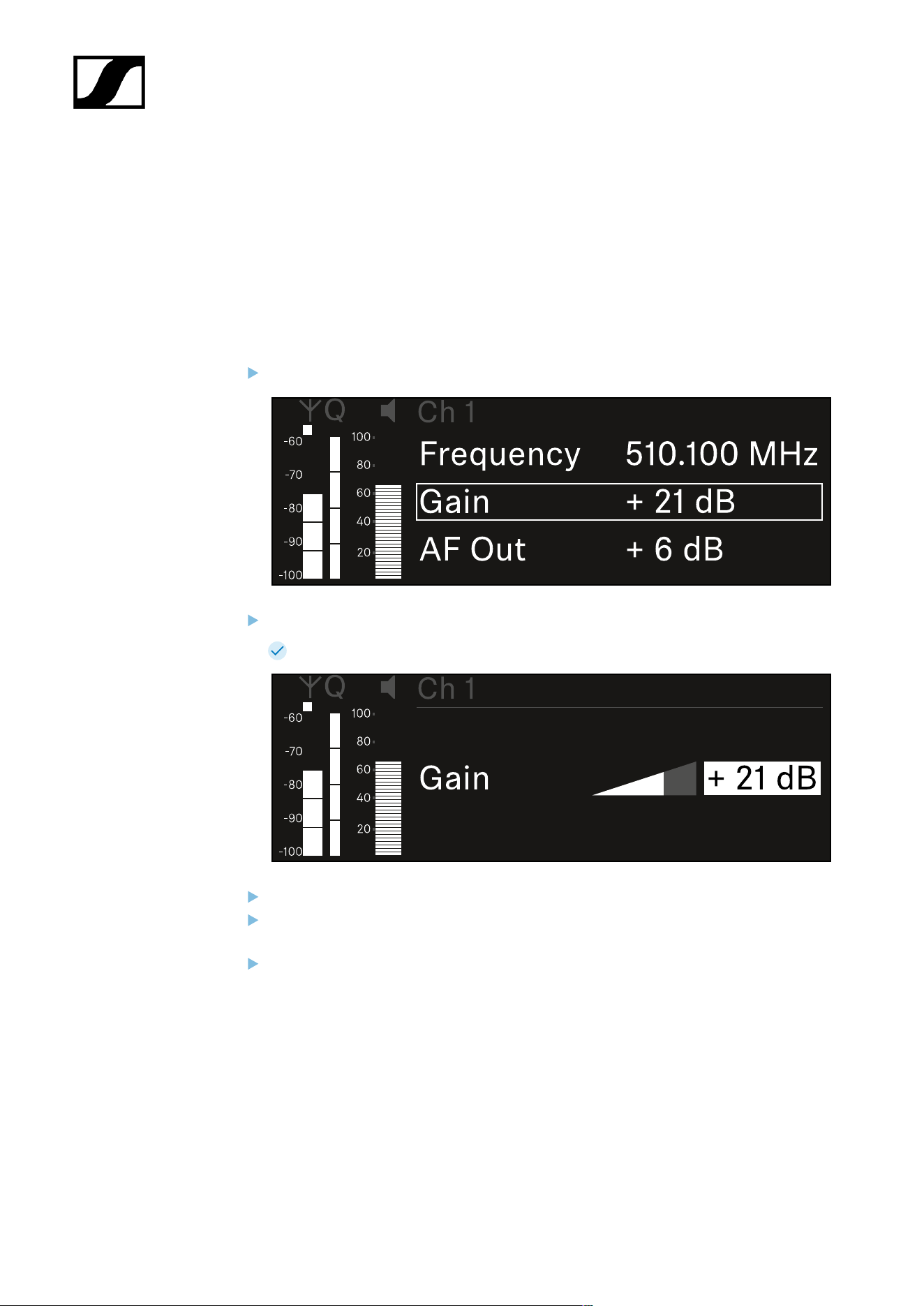
| 3 - Instruction manual
Ch 1 / Ch 2 -> Gain menu item
Under the Gain menu item, you can set the audio level of the audio signal coming from the
received transmitter (e.g. vocals or speech via EW-DX SKM or guitar via EW-DX SK).
• Setting range: -3 dB to +42 dB in increments of 3 dB
To open the Gain menu item:
In the menu, navigate to the Gain menu item for the desired channel.
Press the jog dial to open the menu.
The following view is displayed:
Turn the jog dial to set the desired value.
Press the jog dial to save your setting.
Or
Press the ESC button to cancel the entry without saving the settings.
174

| 3 - Instruction manual
Ch 1 / Ch 2 -> AF Out menu item
In the AF Out menu item, you can set the audio level that is output via the audio outputs of
the particular receiving channel.
To open the AF Out menu item:
In the menu, navigate to the AF Out menu item for the desired channel.
Press the jog dial to open the menu.
The following view is displayed:
Turn the jog dial to set the desired value.
Press the jog dial to save your setting.
Or
Press the ESC button to cancel the entry without saving the settings.
175
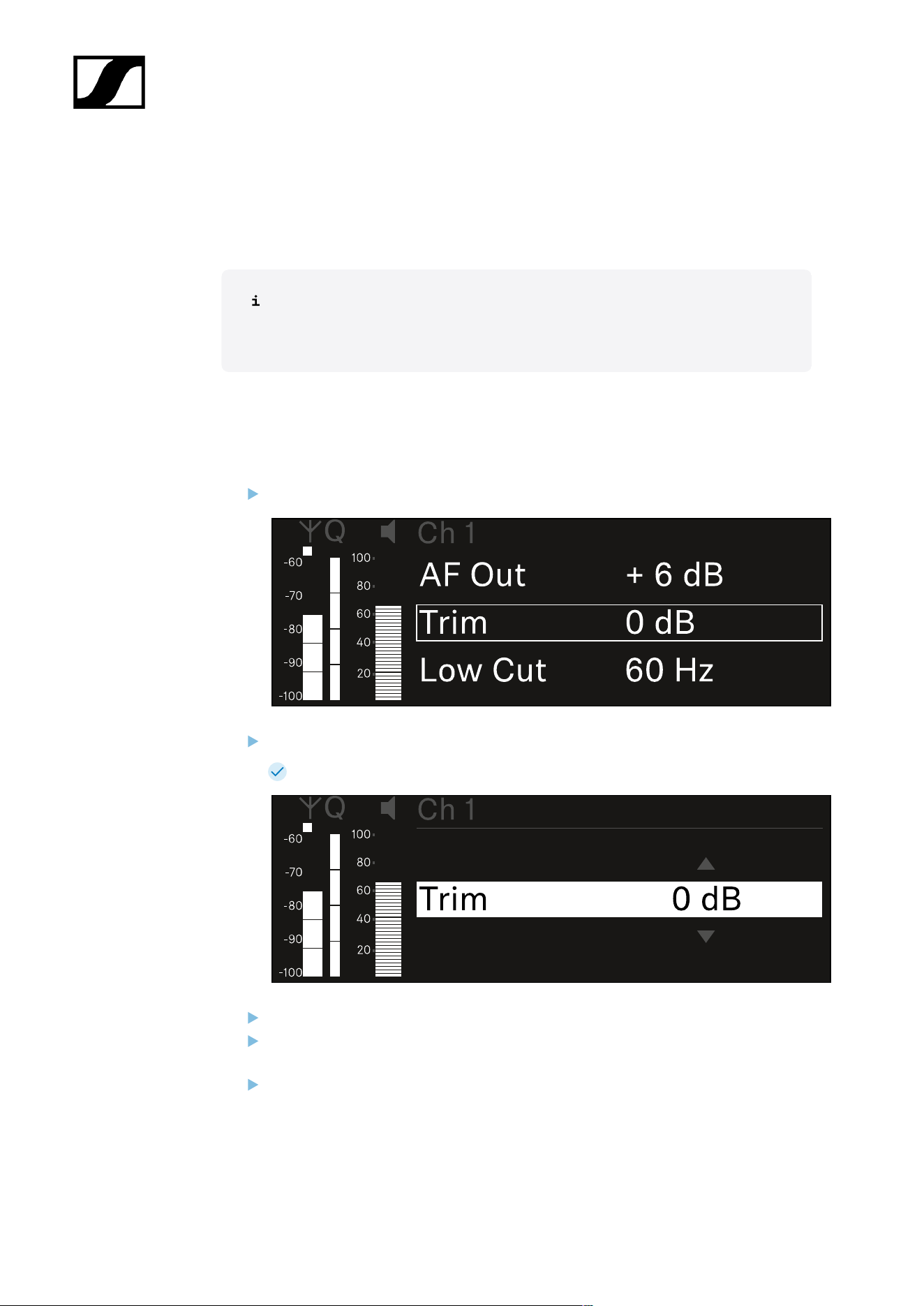
| 3 - Instruction manual
Ch 1 / Ch 2 -> Trim menu item
In the Trim menu item, you can adjust the audio level of the received transmitter to input
signals of different volumes.
For example, if you are using multiple transmitters in alternation for a single
receiving channel, you can adjust the transmitters to the different input signals
using the trim setting. You do not need to change the channel’s gain setting.
• Setting range: -12 dB to +6 dB in increments of 1 dB
To open the Trim menu item:
In the menu, navigate to the Trim menu item for the desired channel.
Press the jog dial to open the menu.
The following view is displayed:
Turn the jog dial to set the desired value.
Press the jog dial to save your setting.
Or
Press the ESC button to cancel the entry without saving the settings.
176

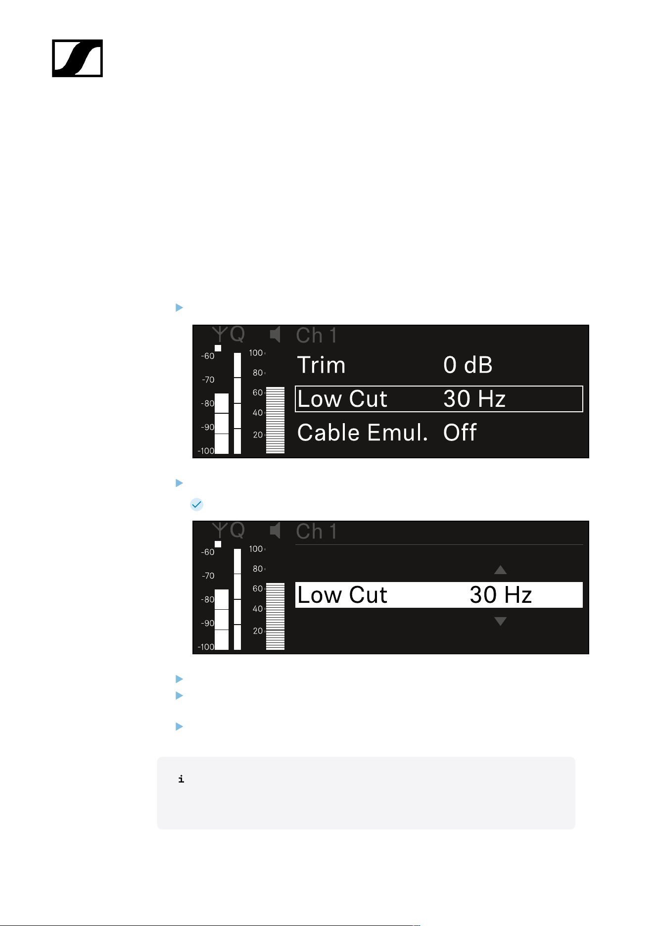
| 3 - Instruction manual
Ch 1 / Ch 2 -> Low Cut menu item
In the Low Cut menu item, you can set the value of the low cut filter for the respective
channel.
Setting range:
• For EW-DX SK | EW-DX SK 3-PIN: Off, 30 Hz, 60 Hz, 80 Hz, 100 Hz, 120 Hz
• For EW-DX SKM | EW-DX SKM-S: 60 Hz, 80 Hz, 100 Hz, 120 Hz
To open the Low Cut menu item:
In the menu, navigate to the Low Cut menu item for the desired channel.
Press the jog dial to open the menu.
The following view is displayed:
Turn the jog dial to set the desired value.
Press the jog dial to save your setting.
Or
Press the ESC button to cancel the entry without saving the settings.
For the set value to be applied to the received transmitter, you must synchronize
the channel (Connecting to the EW-DX EM receivers / synchronizing the EW-
DX EM).
178

| 3 - Instruction manual
Ch 1 / Ch 2 -> Cable Emul. menu item
In the Cable Emul. menu item, you can emulate instrument cable lengths:
Setting range:
• Off, Type 1, Type 2, Type 3
To open the Cable Emul. menu item:
In the menu, navigate to the Cable Emul. menu item for the desired channel.
Press the jog dial to open the menu.
The following view is displayed:
Turn the jog dial to set the desired value.
Press the jog dial to save your setting.
Or
Press the ESC button to cancel the entry without saving the settings.
179

| 3 - Instruction manual
Ch 1 / Ch 2 -> Mute Mode menu item
In the Mute Mode menu item, you can set the function of the mute switch on the connected
transmitter (EW-DX SK, EW-DX SK 3-PIN, EW-DX SKM-S, EW-DX TS).
EW-DX SKM-S, EW-DX SK/EW-DX SK 3-PIN setting range:
• Disabled: The mute switch has no function.
• RF Mute: The RF signal is deactivated when the mute switch is on.
• AF Mute: The audio signal is muted when the mute switch is on.
EW-DX TS setting range:
• Disabled: The MUTE button has no function.
• AF Mute: The audio signal is muted when the MUTE button is pressed. Pressing the
button again activates the audio signal.
• PTT (Push to talk): Press and hold the MUTE button to activate the audio signal.
• PTM (Push to mute): Press and hold the MUTE button to mute the audio signal.
To open the Mute Mode menu item:
In the menu, navigate to the Mute Mode menu item for the desired channel.
Press the jog dial to open the menu.
The following view is displayed:
Turn the jog dial to set the desired value.
Press the jog dial to save your setting.
180


| 3 - Instruction manual
Ch 1 / Ch 2 -> Auto Lock menu item
In the Auto Lock menu item, you can activate or deactivate the lock-off for the received
transmitter.
The lock-off prevents the transmitter from being unintentionally switched off and also
prevents any changes to the transmitter’s menu.
If you want to change settings in the transmitter’s menu while the lock-off is
active, you have to temporarily disable the lock-off:
• EW-DX SKM: Lock-off function
• EW-DX SK: Lock-off function
To open the Auto Lock menu item:
In the menu, navigate to the Auto Lock menu item for the desired channel.
Press the jog dial to open the menu.
The following view is displayed:
Turn the jog dial to set the desired value.
Press the jog dial to save your setting.
Or
Press the ESC button to cancel the entry without saving the settings.
182


| 3 - Instruction manual
Ch 1 / Ch 2 -> LED menu item
The LED menu item allows you to set the behavior of the LINK LED on the received
transmitter.
Setting range:
• ON: The LINK LED remains continuously lit.
• OFF: The LINK LED switches off while the lock-off function is active.
For this to occur, the automatic lock-off function must be enabled in the Auto
Lock menu item (see Ch 1 / Ch 2 -> Auto Lock menu item).
To open the LED menu item:
In the menu, navigate to the LED menu item for the desired channel.
Press the jog dial to open the menu.
The following view is displayed:
Turn the jog dial to set the desired value.
Press the jog dial to save your setting.
Or
Press the ESC button to cancel the entry without saving the settings.
184


| 3 - Instruction manual
Ch 1 / Ch 2 -> Sync Parameters menu item
In the Sync Parameters menu item, you can choose which settings for the transmitter you
want to transfer from the receiver to the transmitter during the synchronization.
All of the settings can also be set separately in the menu on the transmitter.
During synchronization, the values set in the transmitter are overwritten with the
values set in the receiver.
The following parameters can be enabled or disabled for transmission.
• Name
• Frequency
• Trim
• Low Cut
• Cable Emul.
• Mute Mode
• Auto Lock
• LED
To open the Sync Settings menu item:
In the menu, navigate to the Sync Settings menu item for the desired channel.
Press the jog dial to open the menu.
The following view is displayed:
186

| 3 - Instruction manual
Turn the jog dial to choose between the options.
Press the jog dial to open your selected option.
For each option, select whether it will be synchronized or not.
The value set for this function will be transferred during synchronization.
The value set for this function will not be transferred during
synchronization.
Press the jog dial to save your setting.
187
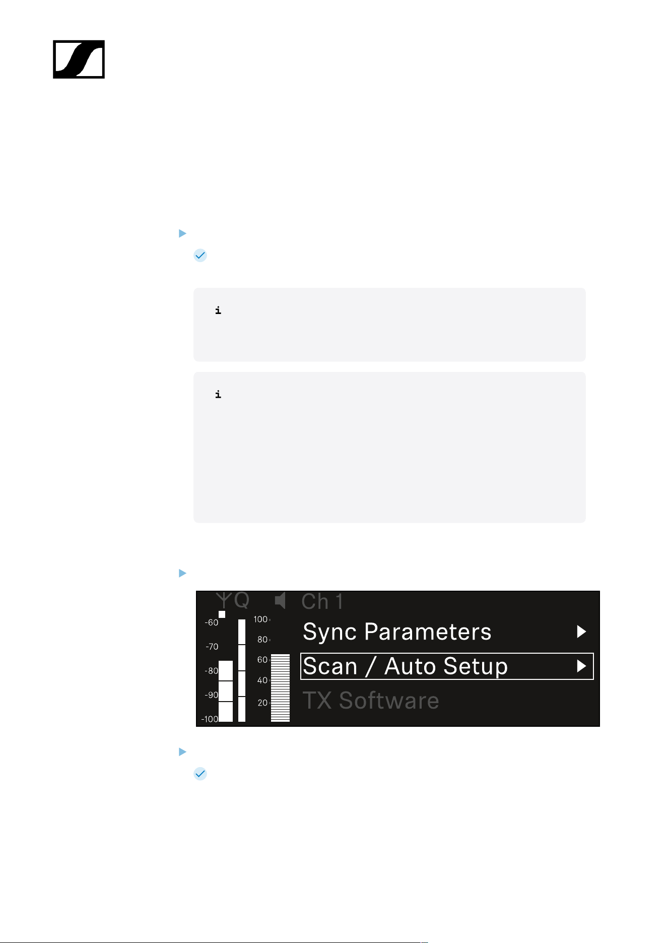
| 3 - Instruction manual
Ch 1 / Ch 2 -> Scan / Auto Setup menu item
The receiver lets you scan the frequency spectrum and display all of the free frequencies in
the selected frequency range. The automatic frequency setup can be used to distribute the
free frequencies to all of the EW-DX EM 2 devices available in the network automatically.
Switch off all transmitters before you perform the scan.
If transmitters are still switched on, they are detected as unavailable frequencies
and the frequencies that are actually available cannot then be used.
To perform the automatic frequency setup for all devices in the network,
the Auto Setup function must be enabled in the receiver’s system menu:
System -> Auto Setup menu item
An EM that is performing one of the following actions will be excluded
from the frequency setup of another EM:
• Remote (full) scan
• Scan Me / Scan Network -> Autosetup
• Bonding
• TX Sync
• TX Update
• Device Update (if in progress)
To open the Scan / Auto Setup menu item:
In the menu, navigate to the Scan / Auto Setup menu item for the desired channel.
Press the jog dial to open the menu.
The following view is displayed:
188

| 3 - Instruction manual
Turn the jog dial to choose between the Scan Me and Scan Network options.
• Scan Me: The frequency scan and the frequency setup are performed only for
the selected receiving channel.
• Scan Network: The frequency scan and the frequency setup are performed for
both channels of the receiver as well as for all other receivers available in the
network.
Press the jog dial to open your selected option.
Select a frequency from which to start the scan.
Press the jog dial to start the scan.
The spectrum is scanned for free frequencies above the selected frequency.
After the scan free frequencies are displayed, which you can then assign
to the channels.
189

| 3 - Instruction manual
Press the jog dial to assign the free frequencies to the receiving channels.
Or
Press the ESC key to cancel and not assign new frequencies.
Next, synchronize the receiving channels with the corresponding transmitters to
establish the radio link at the new selected frequencies (Synchronizing the receiver
and transmitter).
190

| 3 - Instruction manual
Ch 1 / Ch 2 -> Walktest menu item
The Walktest menu item allows the performance of a reception test.
Once you have set up and installed all of the receivers and transmitters for your event, we
recommend performing a walk test. This lets you check whether sufficient reception strength
is available throughout the entire area used.
Start the walktest function in this menu item and then walk the entire area with one
transmitter. The results of the walk test give you information about the reception quality.
Opening the Walktest menu item
In the menu, navigate to the Walktest menu item for the desired channel.
Press the jog dial to open the menu.
The following view is displayed:
To start the reception test:
Press the jog dial.
Walk the entire area on which you want to operate the system with the transmitter.
The following values are recorded on the display:
• RF: Reception from antenna in dBm
• LQI: Connection quality as a %, see Meaning of the Link Quality Indicator
• AF: Transmitter audio frequency in dBFS
191

| 3 - Instruction manual
To end the reception test:
Press the Jog-Dial to finish the walk test when you are ready.
192

| 3 - Instruction manual
Ch 1 / Ch 2 -> TX Software menu item
The TX Software menu item displays the software version of the received transmitter.
You cannot open this menu item to make settings.
In the menu, navigate to the TX Software menu item for the desired channel.
The version number of the transmitter software is shown on the display. The
transmitter must be switched on for this to be displayed.
You can find information about updating the transmitter firmware in section
System -> TX Update menu item.
193

| 3 - Instruction manual
System menu item
In the System menu, you can make system-wide settings that will affect the entire device and
not only the respective receiving channel.
The following menu items are available:
Link Encryption
• This menu item lets you secure the radio link with AES 256 encryption.
• System -> Link Encryption menu item
Link Density
• In this menu item, you can set the required transmission mode.
• System -> Link Density menu item
Network
• In this menu item, you can configure the settings for the network connection.
• System -> Network menu item
TX Update
• This menu item lets you perform a firmware update for the transmitters.
• System -> TX Update menu item
Auto Setup
• This menu item allows you to activate automatic frequency setup for the receiver.
• System -> Auto Setup menu item
This Device
• This menu item allows you to enter a device name and display information about the
receiver’s hardware and software.
• System -> This Device menu item
System -> Link Encryption menu item
You can secure the radio link between the transmitter and receiver using AES 256
encryption.
194
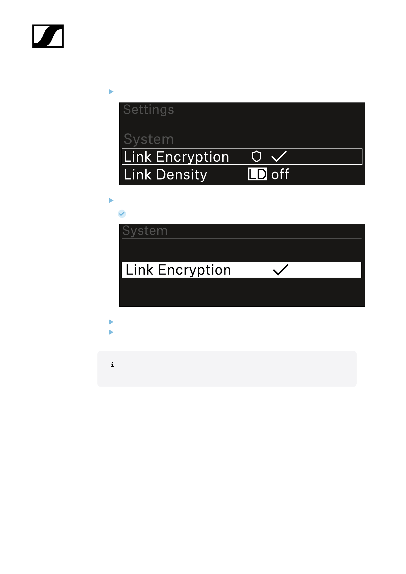
| 3 - Instruction manual
To open the Link Encryption menu item:
In the System menu, navigate to the Link Encryption menu item.
Press the jog dial to open the menu.
The following view is displayed:
Turn the jog dial to choose between the On and Off options.
Press the jog dial to save your setting.
After enabling AES 256 encryption, the connected transmitter must be
resynchronized with the receiver to enable encryption on the transmitter as well.
195
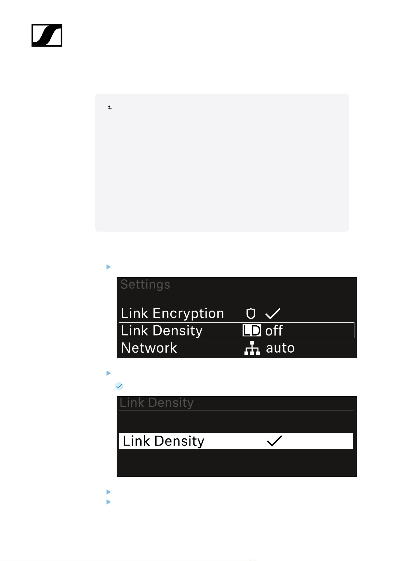
| 3 - Instruction manual
System -> Link Density menu item
Link Density mode (LD mode)
LD mode doubles the number of usable carrier frequencies in the available
spectrum, as the minimum distance for the equidistant frequency grid is halved.
This is achieved by reducing the modulation bandwidth of the transmitter. This
means that a much smaller frequency spacing between neighboring frequencies
can be selected, and therefore more frequencies can be used in the same
available spectrum without intermodulation.
LD mode is recommended if the following criteria are met:
• The required number of channels cannot be achieved using the normal
mode, as there may be only a small spectrum available.
• The distance between the transmitters and the antennas is not too great.
To open the Link Density menu item:
In the System menu, navigate to the Link Density menu item.
Press the jog dial to open the menu.
The following view is displayed:
Turn the jog dial to choose between the On and Off options.
Press the jog dial to save your setting.
196
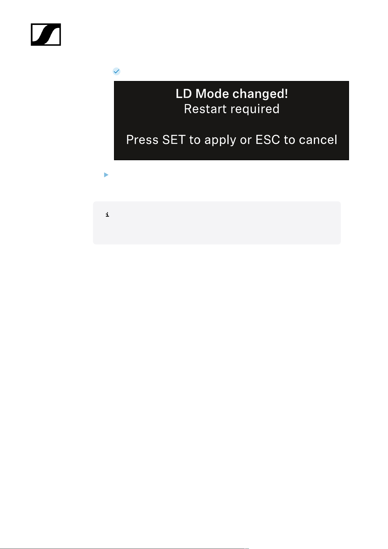
| 3 - Instruction manual
If you have enabled LD mode, the receiver must be restarted.
Press the jog dial to restart the receiver,
a. or press the ESC button to cancel the mode change.
After enabling LD mode and restarting the receiver, the connected transmitter
must be resynchronized with the receiver to enable LD mode on the transmitter
as well.
197
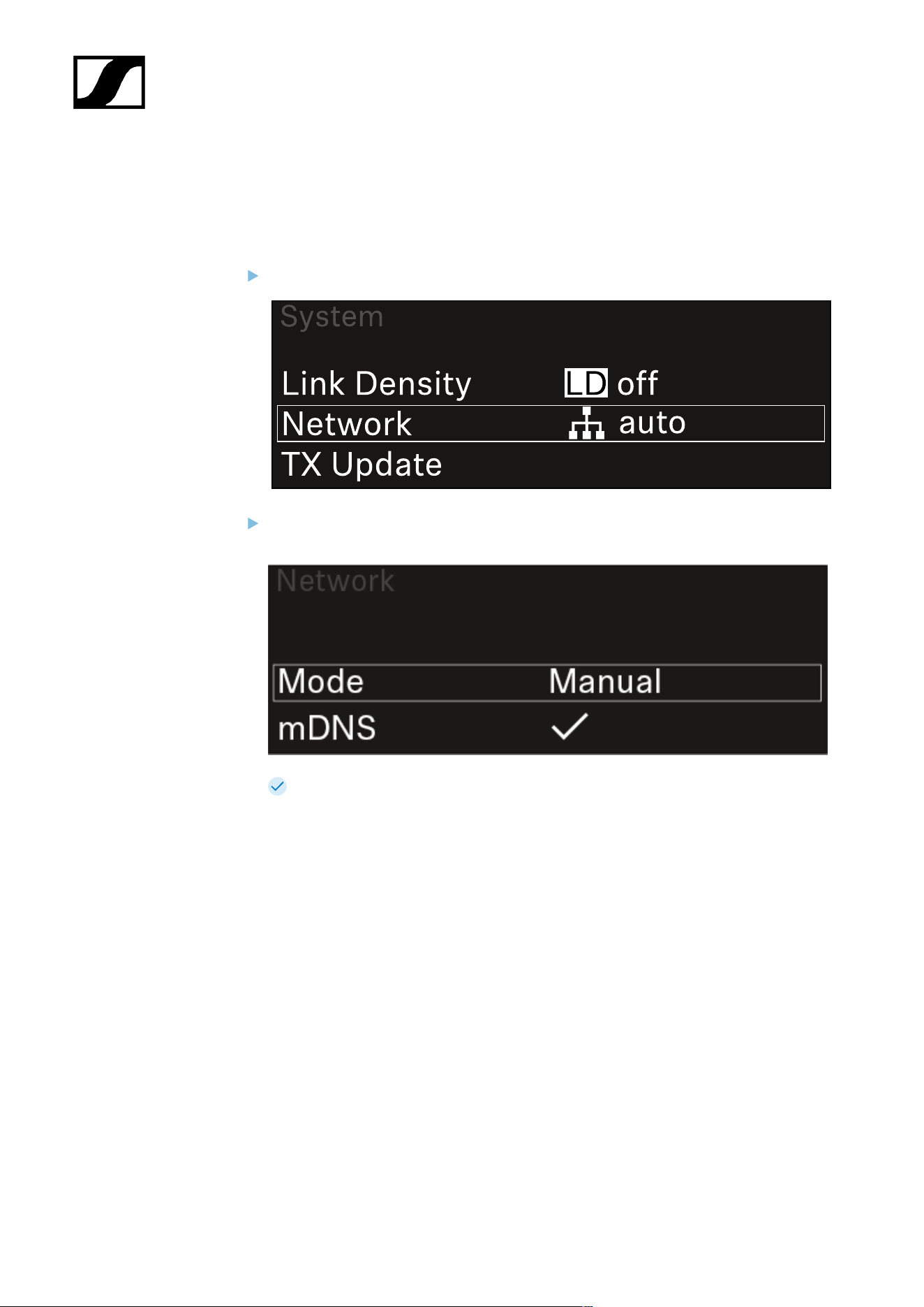
| 3 - Instruction manual
System -> Network menu item
In this menu item, you can configure the settings for the network connection.
To open the Network menu item:
In the System menu, navigate to the Network menu item.
Rotate the jog dial to navigate through the Network menu and select the desired
menu item.
You can make the following settings here:
Mode
• Auto: The network configuration is performed automatically.
• Manual: The network configuration can be performed manually.
mDNS
• You can enable or disable this option if you want to use mDNS for automatic
device detection in the network.
IP
• If the Mode option is set to Auto, the automatically assigned IP address is
displayed here.
• If the Mode option is set to Manual, you can set the IP address here.
Netmask
• If the Mode option is set to Auto, the automatically assigned netmask is
displayed here.
• If the Mode option is set to Manual, you can set the netmask here.
198
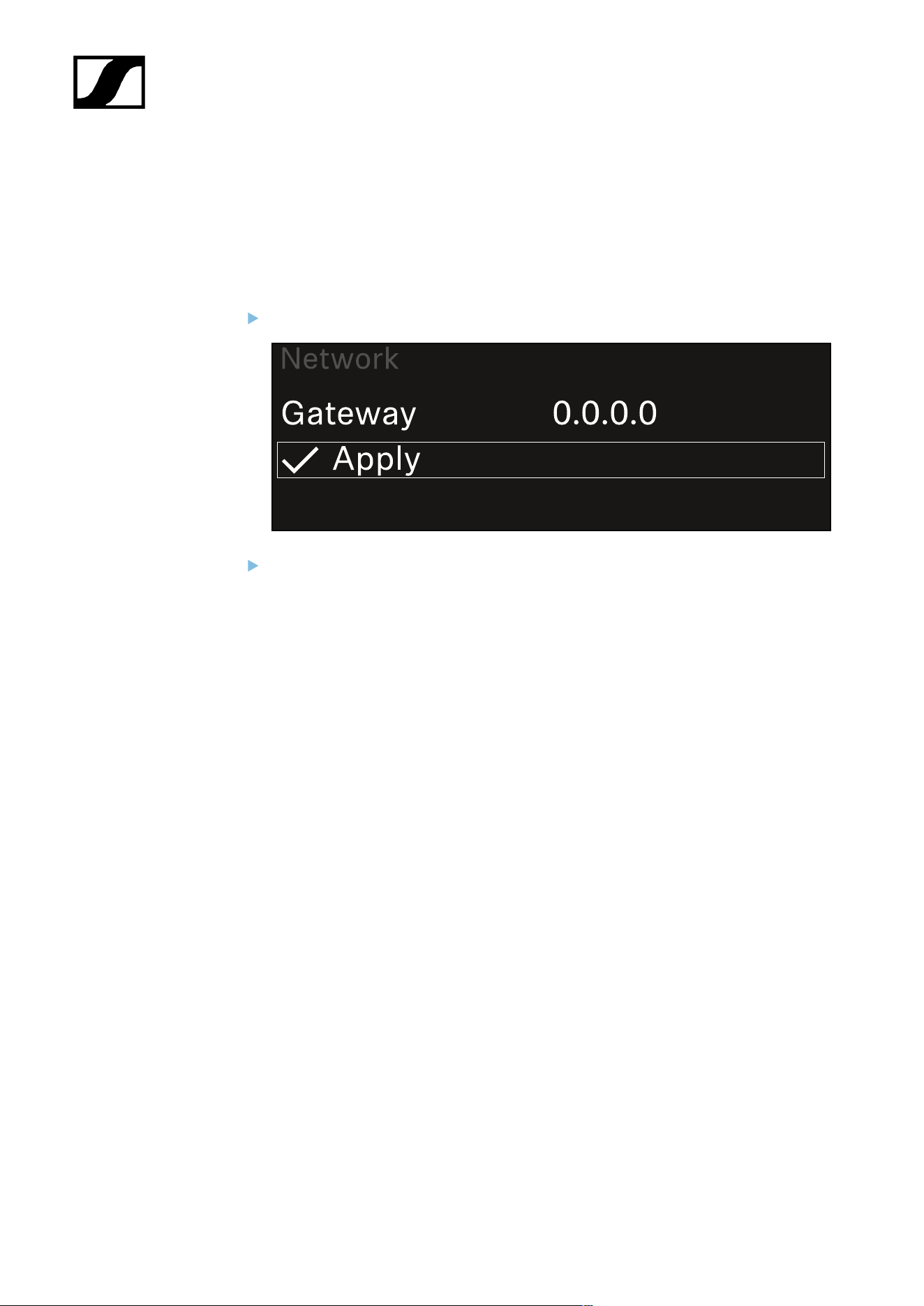
| 3 - Instruction manual
Gateway
• If the Mode option is set to Auto, the automatically assigned gateway is
displayed here.
• If the Mode option is set to Manual, you can set the gateway here.
To save the settings you have made:
Turn the jog dial until Apply appears in the selection frame.
Press the jog dial to save your settings.
199
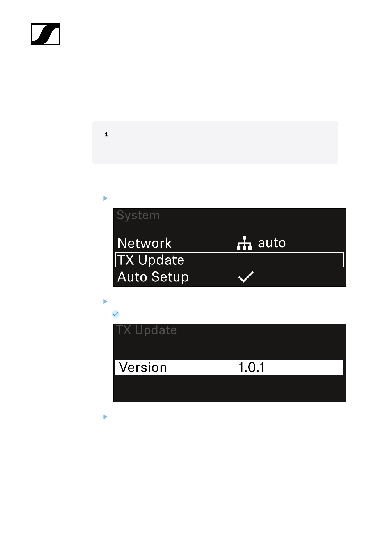
| 3 - Instruction manual
System -> TX Update menu item
This menu item lets you perform a firmware update for the transmitters. This update is
recommended after you perform a firmware update for the receiver (see Updating the
firmware of the receiver).
The firmware versions currently installed on the connected transmitter can be
viewed under the TX Software menu item for the respective channel (see Ch 1 /
Ch 2 -> TX Software menu item).
To open the TX Update menu item:
In the System menu, navigate to the TX Update menu item.
Press the jog dial to open the menu.
The available sender firmware is displayed:
Press the jog dial to start the firmware update.
200

| 3 - Instruction manual
Press the SYNC button on the connected transmitter for 3 seconds.
You have about 20 seconds to do this. The progress bar shows the remaining
time.
The system carries out the firmware update for the transmitter.
The progress of the update is shown on the receiver’s display.
The transmitter’s display shows that the firmware update is in progress.
201

| 3 - Instruction manual
NOTICE
Canceling the update can impair the function of the transmitter
If the transmitter is turned off during the firmware update, the update
may fail and the transmitter may cease to function correctly.
Do not turn off the transmitter during the update.
Do not remove the batteries or rechargeable battery pack during
the update.
Make sure that the transmitter’s (rechargeable) batteries are
sufficiently charged before updating.
202
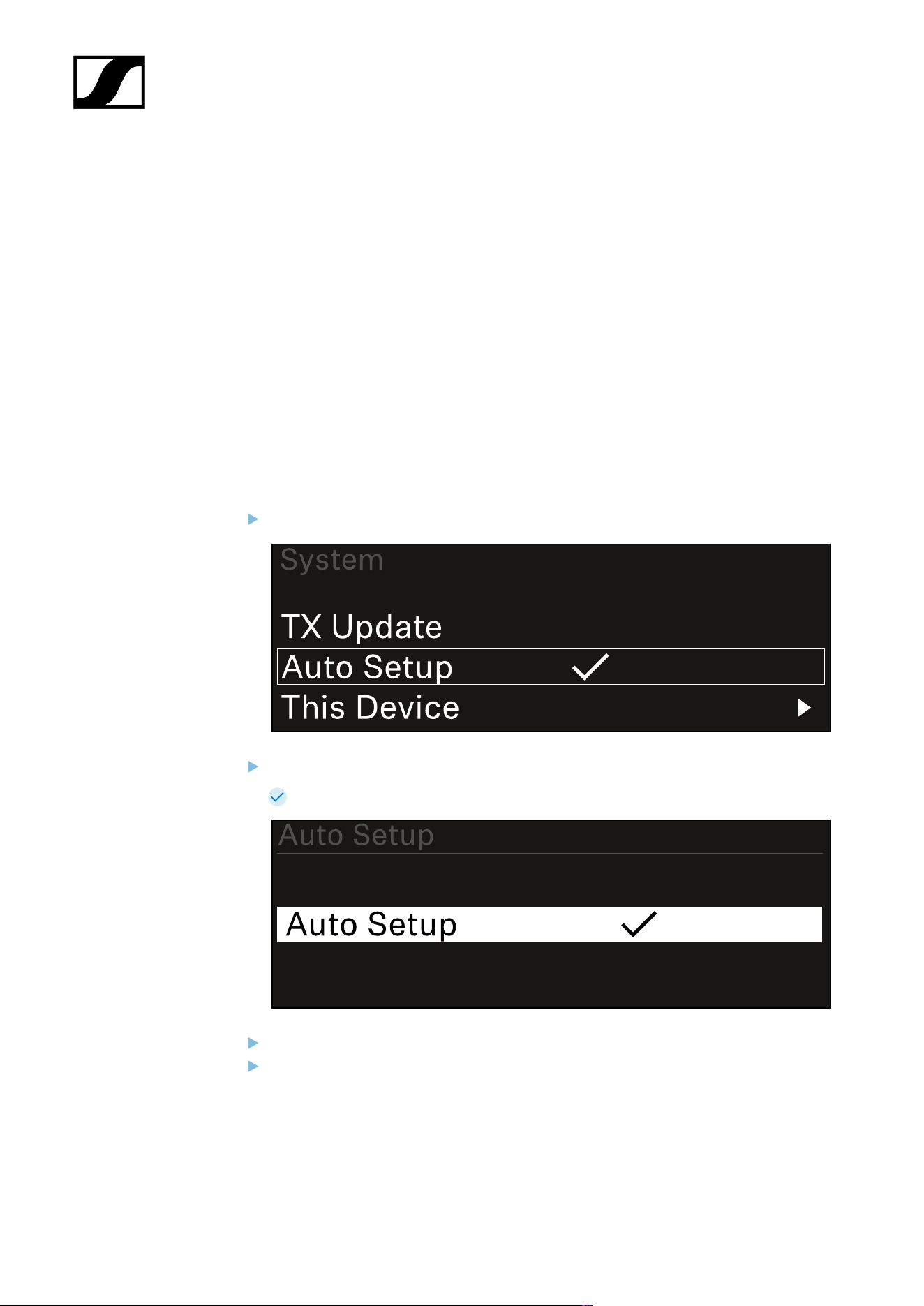
| 3 - Instruction manual
System -> Auto Setup menu item
In this menu item, you can activate the Auto Setup function for the receiver.
If the function is activated here, you can perform an automatic frequency setup for both
channels of this receiver via the Scan / Auto Setup menu item.
See Ch 1 / Ch 2 -> Scan / Auto Setup menu item.
The receiver will also be enabled for automatic frequency setup in a network consisting of
multiple receivers.
If the function is disabled here, you can only assign a frequency to the selected channel of
the receiver via the Scan / Auto Setup menu item.
To open the Auto Setup menu item:
In the System menu, navigate to the Auto Setup menu item.
Press the jog dial to open the menu.
The following view is displayed:
Turn the jog dial to choose between the On and Off options.
Press the jog dial to save your setting.
203

| 3 - Instruction manual
System -> This Device menu item
This menu item allows you to change the device name, view software and hardware
information, or reset the device to factory settings.
To open the This Device menu item:
In the System menu, navigate to the This Device menu item.
Press the jog dial to open the menu.
The following view is displayed:
Choose from the following:
• Device Lock: Set the lock-off of the receiver.
• Brightness: Set the brightness of the display.
• Device Name: Open this menu item to change the device name. This receiver
will be displayed in the network under this name.
• MAC: Shows the MAC address of the receiver.
• Software: Shows the software version of the receiver.
• HW Main/HW Front/HW Tuner: Displays the hardware versions of the boards
installed in the receiver.
• Reset:
• Audio Ch1 | Audio Ch2 | Audio All (EW-DX EM 2 / EW-DX EM 2
Dante): resets selected audio channel settings or all audio channel
settings to their default.
• Audio Ch1 | Audio Ch2 | Audio Ch3 | Audio Ch4 | Audio All (EW-
DX EM 4 Dante): resets selected audio channel settings or all audio
channel settings to their default.
204

| 3 - Instruction manual
• Network: resets the network settings and the claiming password to
their factory settings.
• Factory: resets the receiver to factory settings.
205

| 3 - Instruction manual
Updating the firmware of the receiver
You can update the receiver firmware using the Sennheiser Control Cockpit software, the
Wireless Systems Manager software or the Smart Assist app.
Updating with the Sennheiser Control Cockpit or the Wireless Systems Manager:
Connect the receiver to a network (see Connecting receivers in a network) and
establish the connection with the software.
For more information about controlling devices with the Sennheiser
Control Cockpit or Wireless Systems Manager software, refer to the
software help.
You can download the software here:
sennheiser.com/scc
sennheiser.com/wsm
To update the transmitter’s firmware, go to System -> TX Update in the
menu on the receiver. See System -> TX Update menu item
Updating with the Smart Assist app:
Connect the receiver to a network (see Connecting receivers in a network).
Connect a wireless access point to the network.
Connect your smartphone to this network.
Start the update process in the Smart Assist app:
Click on “Update” if the device is on the network.
Follow the instructions.
Or
Search for devices that can be updated.
Follow the instructions.
206

| 3 - Instruction manual
EW-DX EM 2 Dante rack receiver
Product overview
Front
1 Headphone socket
• See Using the headphone output
2 Volume control for the headphone socket
• See Using the headphone output
3 CH 1 LED to indicate the status of channel 1
• See Meaning of the LEDs
4 CH 1 button for selecting channel 1
• See Displays on the receiver’s display panel
• See Buttons for navigating the menu
5 CH 2 LED to indicate the status of channel 2
• See Meaning of the LEDs
6 CH 2 button for selecting channel 2
• See Displays on the receiver’s display panel
• See Buttons for navigating the menu
207
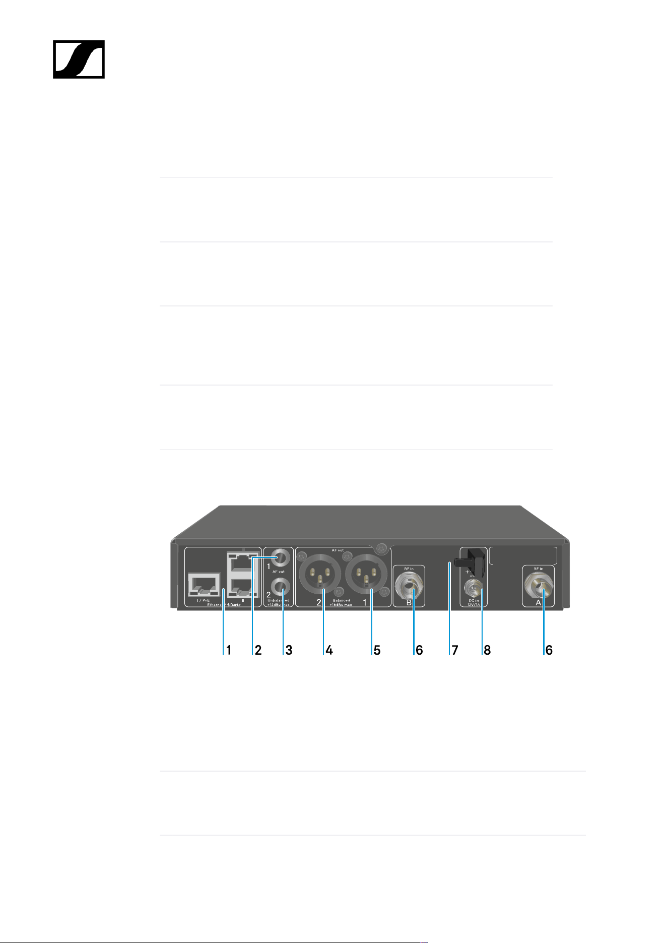
| 3 - Instruction manual
7 Display for status information and operating menu
• See Displays on the receiver’s display panel
8 Jog dial (UP/DOWN/SET) for navigating the operating menu
• See Buttons for navigating the menu
9 ESC button for canceling an action in the menu
• See Buttons for navigating the menu
10 SYNC button for synchronizing the transmitter and receiver
• See Establishing a radio link | Synchronizing the receiver and
transmitter
11 ON/OFF button for switching the device on and off
• See Switching the receiver on and off
Back
1 RJ-45 sockets: I/PoE (power supply via Power over Ethernet), II + III (control of the device
via network using Wireless Systems Manager / Sennheiser Control Cockpit and Dante)
• See Connecting receivers in a network
• See Connecting/disconnecting the receiver to/from the power supply system
2 6.3 mm jack socket for AF out Unbalanced audio output for channel 1
• See Outputting audio signals
208

| 3 - Instruction manual
3 6.3 mm jack socket for AF out Unbalanced audio output for channel 2
• See Outputting audio signals
4 XLR-3 socket for AF out Balanced audio output for channel 2
• See Outputting audio signals
5 XLR-3 socket for AF out Balanced audio output for channel 1
• See Outputting audio signals
6 BNC sockets ANT 1 RF in and ANT 2 RF in for antenna inputs
• See Connecting antennas
7 Strain relief for the connection cable of the power supply unit
• See Connecting/disconnecting the receiver to/from the power supply system
8 DC in connection socket for the power supply unit
• See Connecting/disconnecting the receiver to/from the power supply system
209
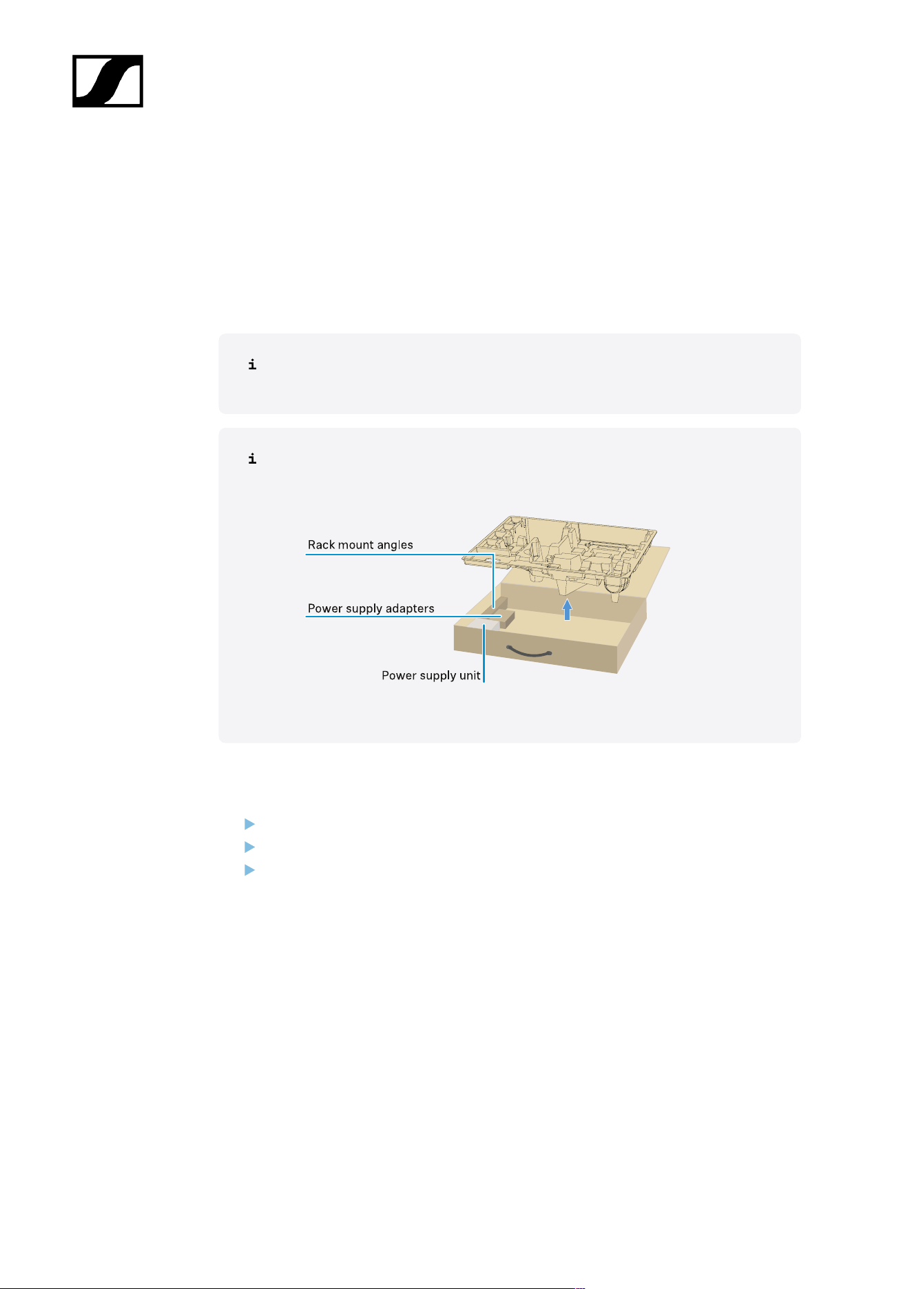
| 3 - Instruction manual
Connecting/disconnecting the receiver to/from the power supply
system
You can operate the receiver using either the included power supply unit or with Power over
Ethernet (PoE IEEE 802.3af Class 0). Please refer to the following information.
Power from the power supply unit
If using a power supply unit, use only the power supply unit included with the
device. It is designed for your receiver and ensures safe operation.
You will find the power supply unit and the country adapters in the packaging
under the tray:
To connect the receiver to the power supply system:
Insert the plug of the power supply unit into the DC in socket on the receiver.
Pass the cable of the power supply unit through the strain relief.
Slide the supplied country adapter onto the power supply unit.
210
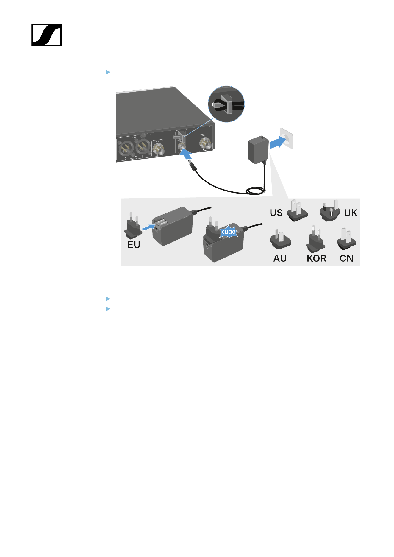
| 3 - Instruction manual
Plug the power supply unit into the wall socket.
To completely disconnect the receiver from the power supply system:
Unplug the power supply unit from the wall socket.
Unplug the power supply unit from the DC in socket on the receiver.
211
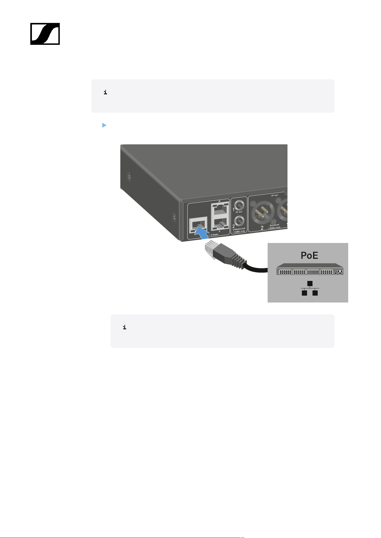
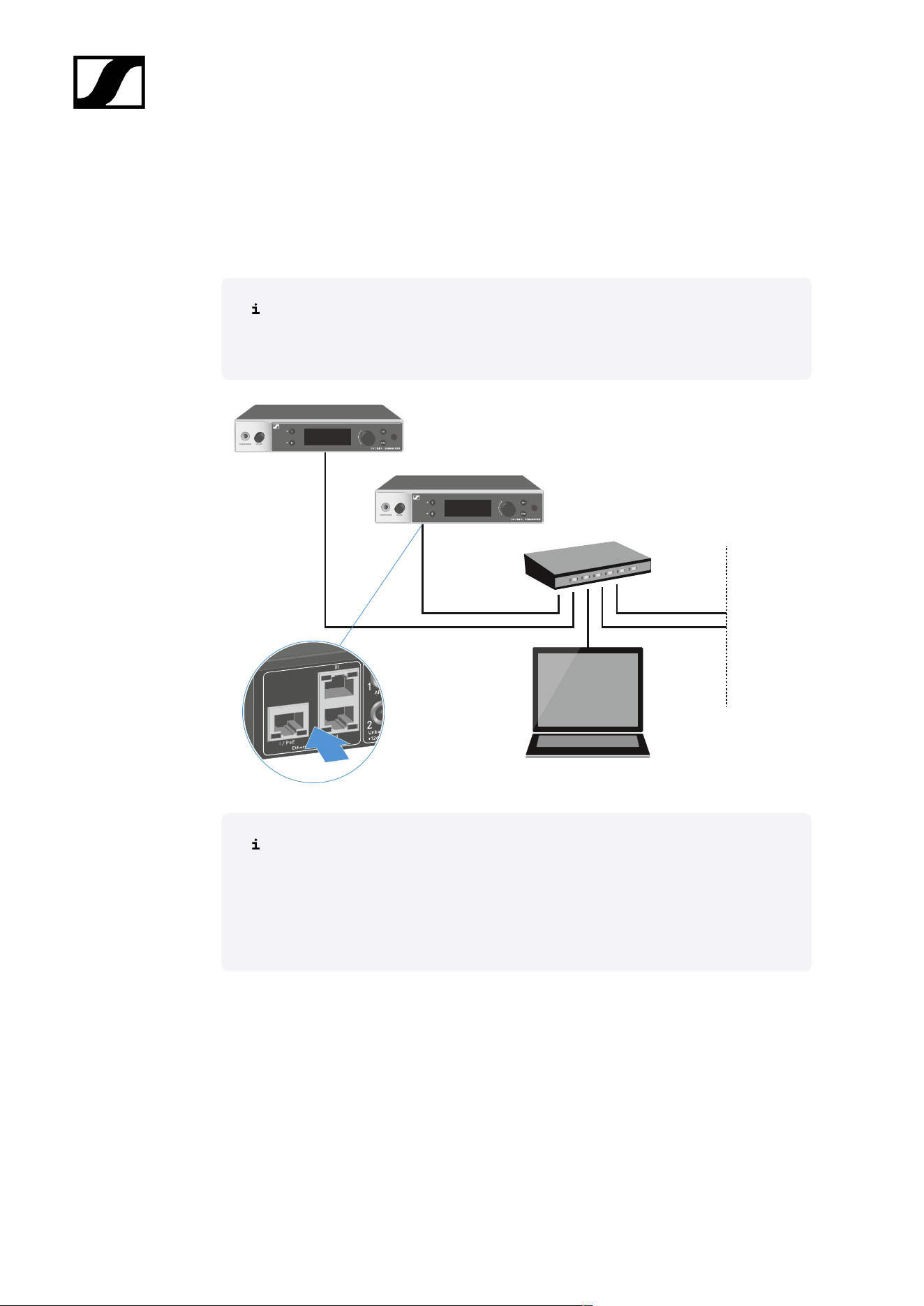
| 3 - Instruction manual
Connecting receivers in a network
You can monitor and control one or more receivers via a network connection using the
Sennheiser Wireless Systems Manager (WSM) or Sennheiser Control Cockpit (SCC)
software.
The network does not have to be a homogeneous network including only
receivers. You can integrate the receiver into your existing network infrastructure
with any other types of devices.
For more information about controlling devices via the Sennheiser Wireless
Systems Manager or Sennheiser Control Cockpit software, refer to the
instruction manual for the software. You can download the software here:
sennheiser.com/wsm
sennheiser.com/scc
213
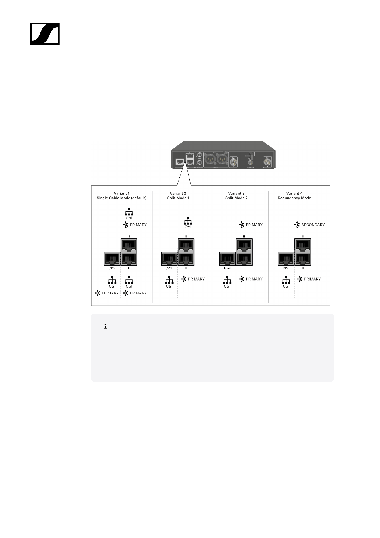
| 3 - Instruction manual
Connecting receivers in a Dante® network
Assignment of the network connections
The network connections have a different assignment depending on the network mode set.
The network mode can be changed in the Network menu, see System -> Network menu
item.
PoE = Power over Ethernet
Ctrl = network control via e.g. Wireless Systems Manager (WSM), Sennheiser
Control Cockpit (SCC) or third-party media control
PRIMARY = Dante® primary
SECONDARY = Dante® secondary
Information
The EW-DX EM 2 Dante and EW-DX EM 4 Dante receivers are equipped with a versatile
network interface with selectable network modes for flexible signal transmission. Further
information is available on the following pages.
In compact network systems that only have a limited number of receivers, the “Single Cable”
mode is the best option. This straightforward setup simplifies the installation and reduces the
cabling workload.
214

| 3 - Instruction manual
For larger, more extensive network configurations, the “Split or Redundancy Mode” is
recommended. In these operating modes, the differing control data can be wired separately
alongside the digital audio protocol data and also allow for redundant cabling.
When integrating several switches in a network, it is important to carefully consider the
possible effects on the network performance. A selected operating mode can, if the cabling
is faulty, restrict the network operation or lead to system failure. In this respect, it is also
important to ensure that the network switches from the respective manufacturers that
are used also support the data and audio protocols (e.g. Dante) and that they have been
configured accordingly.
The Spanning Tree Protocol (STP) has been implemented to avoid misconfigurations between
network modes and cabling and the resulting broadcast storms. The STP is configured with a
priority of 57344 and should be considered when setting up a network with managed switch
so that an EW-DX EM doesn't get the route bridge. STP could be enabled or disabled.
Detailed instructions can be obtained from the respective manufacturers of the individual
software applications.
First of all, set the network mode in the receiver, see EW-DX EM 2 Dante System ->
Network menu item and EW-DX EM 4 Dante System -> Network menu item.
Note the assignment of the sockets and the wiring examples on the following pages.
The following examples do not show all of the cabling options.
Connect the cables.
Information about the Dante Controller and the Dante network protocol settings
is available on the Audinate website: audinate.com.
Information on the use of remote software is available in the download area of
the Sennheiser website: sennheiser.com/download.
215
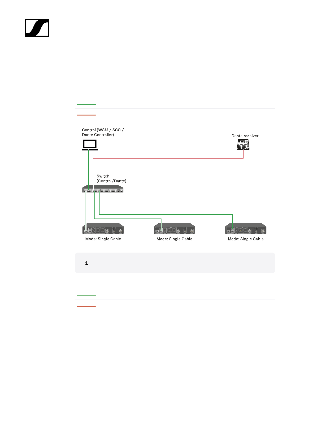
| 3 - Instruction manual
Connections and network settings
Single cable mode
Factory setting
Network control / Dante primary
Dante primary
The cable can be connected to network connections I, II or III.
Daisy-chain
Network control / Dante
Dante
216
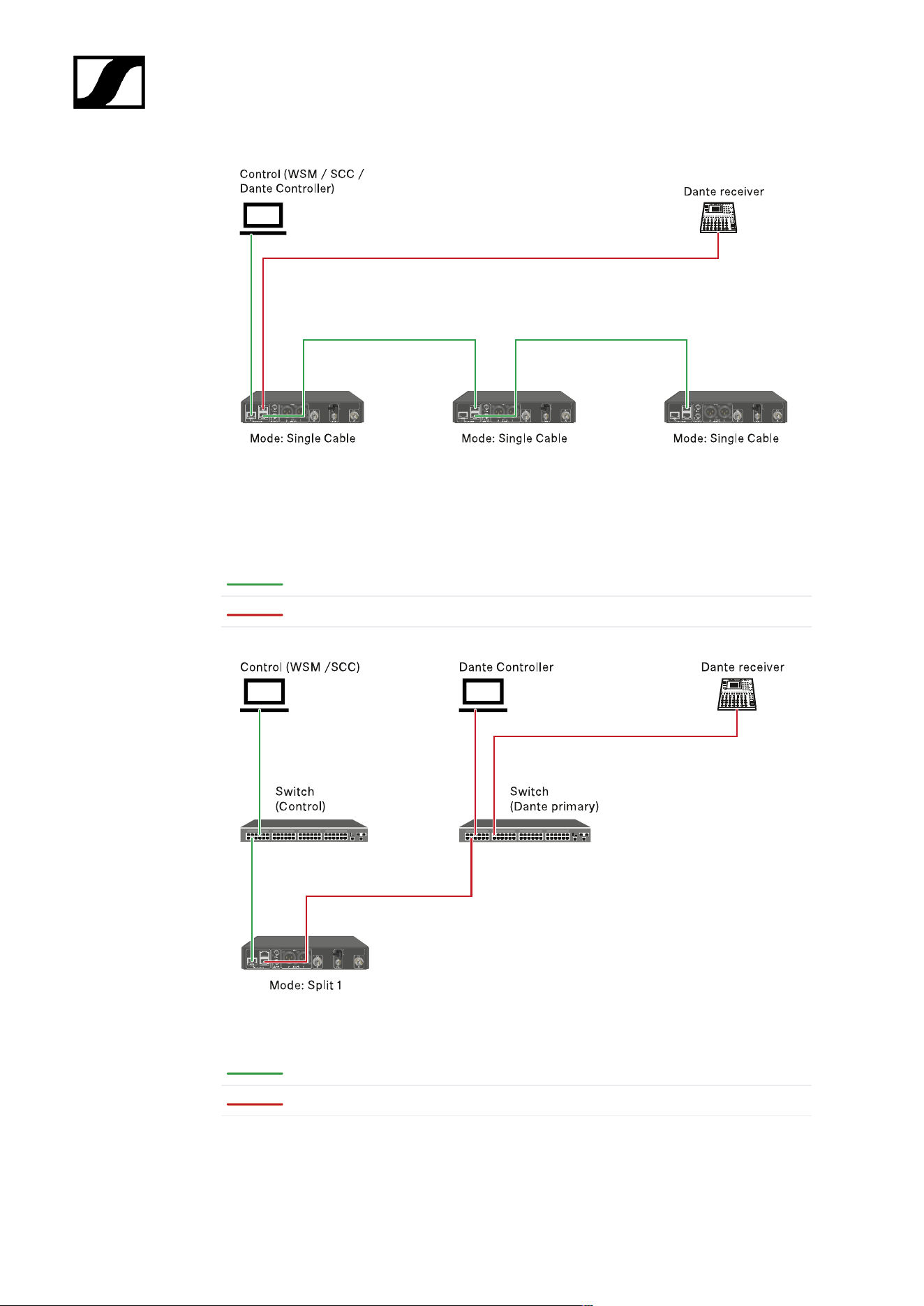
| 3 - Instruction manual
Split mode 1
Split 1 without daisy-chain
Network control
Dante primary
Split 1 with daisy-chain
Network control
Dante primary
217
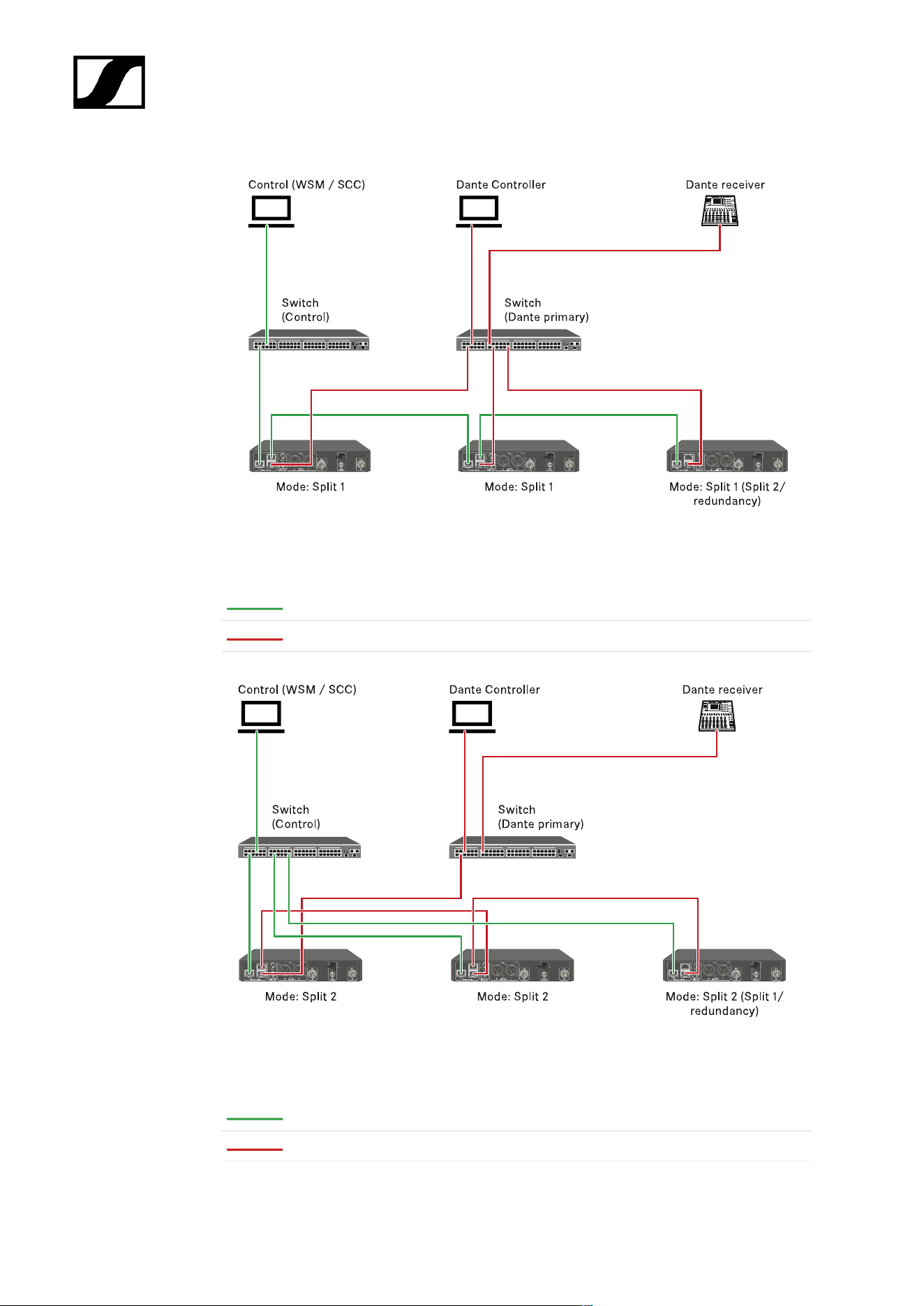
| 3 - Instruction manual
Split mode 2
Network control
Dante primary
Redundancy mode
Network control
Dante primary
218
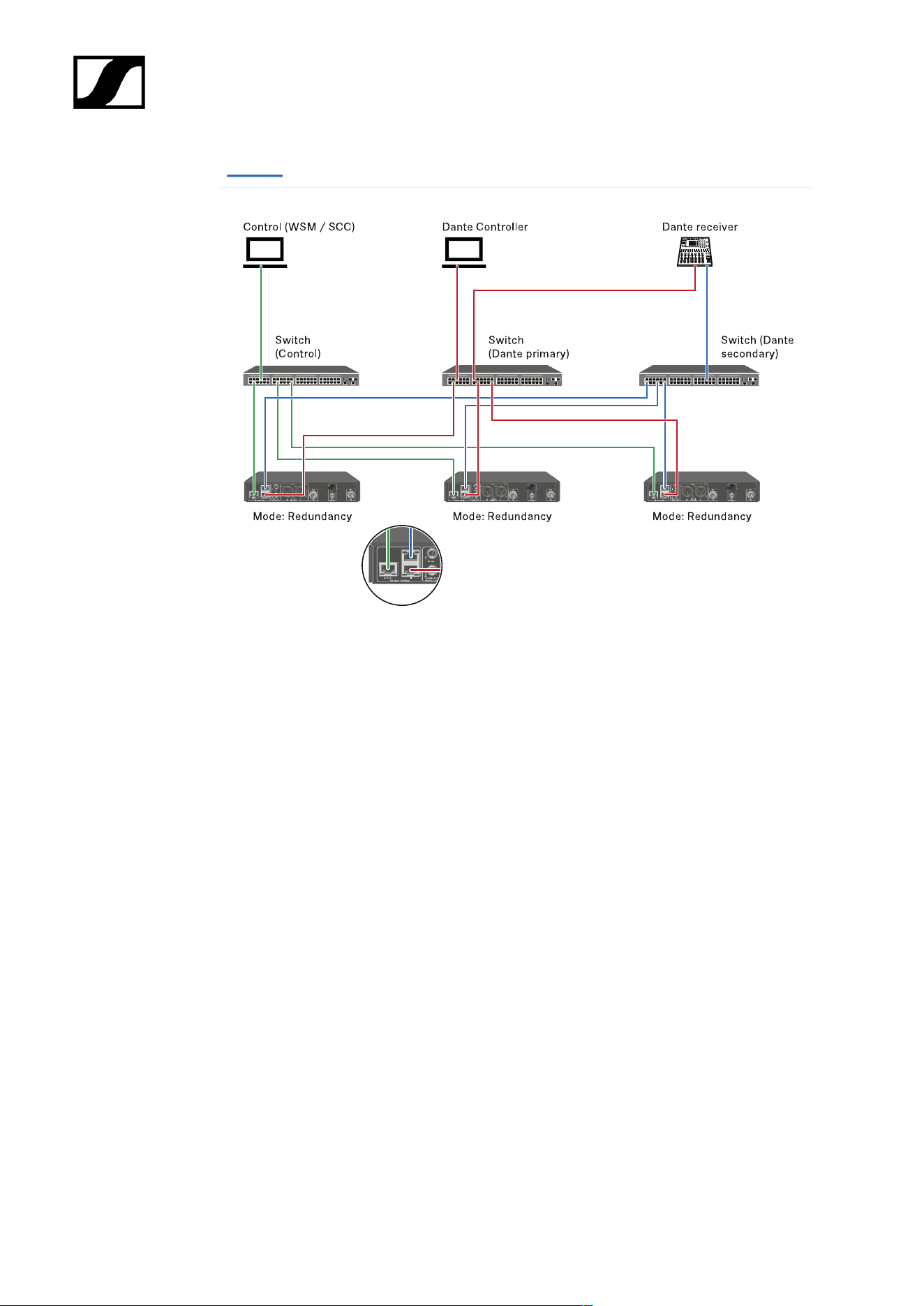
| 3 - Instruction manual
Dante secondary
219
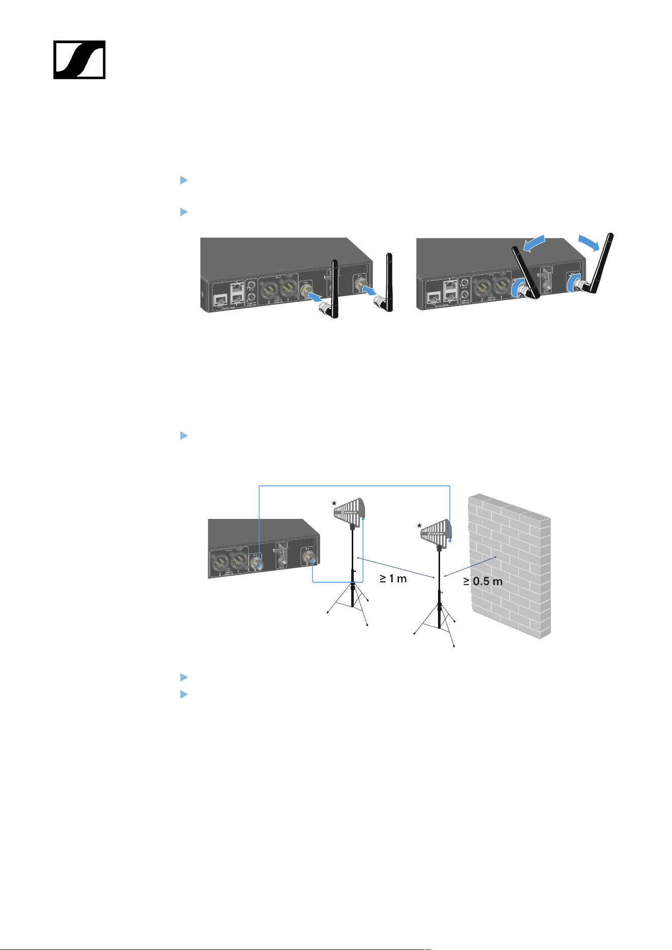
| 3 - Instruction manual
Connecting antennas
To connect the supplied rod antennas:
Connect the antennas to the two antenna inputs on the receiver as shown in the
figure.
Slightly angle the antennas to the left and right as shown in the figure.
If you are using more than one receiver, we recommend using remote antennas and
possibly the EW-D ASA antenna splitter (EW-D ASA antenna splitter).
To connect remote antennas:
Connect the antennas to the two antenna inputs on the receiver as shown in the
figure.
Observe the specified minimum spacing.
Observe the specified minimum spacing to the transmitters.
220
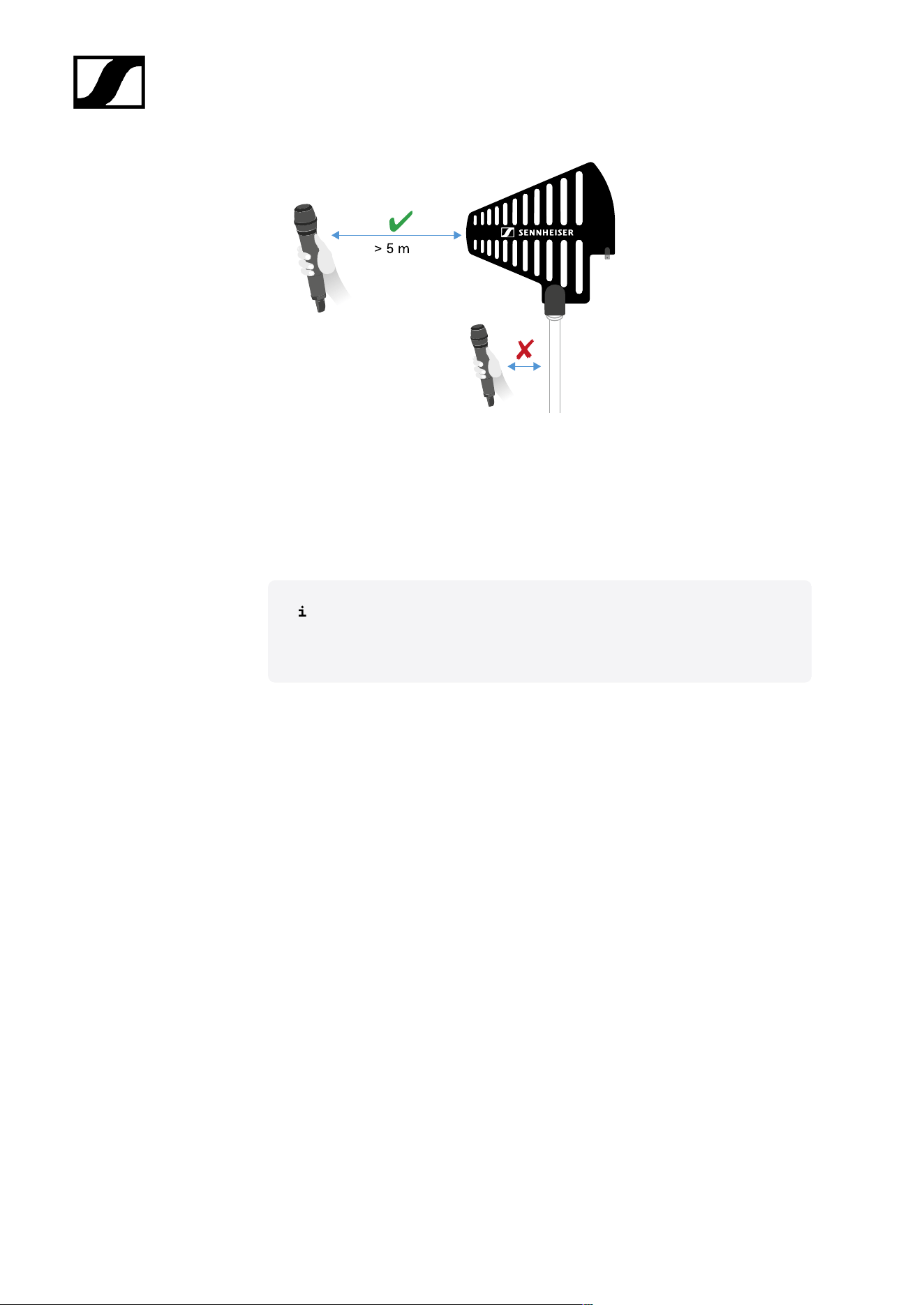
| 3 - Instruction manual
*Recommended antennas:
• ADP UHF | 470 – 1075 MHz
• AD 1800 | 1400 – 2400 MHz
• AWM UHF I | 470 – 694 MHz
• AWM UHF II | 823 – 1075 MHz
• AWM 1G8 | 1785 – 1805 MHz
If you are using more than one receiver, we recommend using remote
antennas and possibly the EW-D ASA antenna splitter (EW-D ASA
antenna splitter).
221
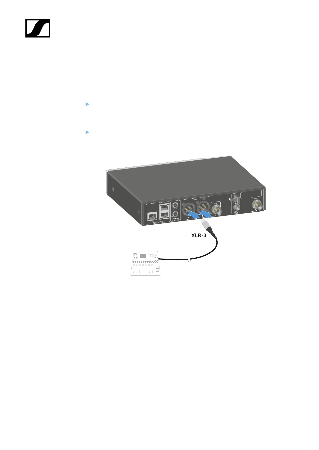
| 3 - Instruction manual
Outputting audio signals
Each of the two channels on the EW-DX EM 2 Dante has both a balanced XLR-3M output
socket and an unbalanced 6.3 mm (1/4") jack output socket.
Always use only one of the two output sockets for each channel.
To connect an XLR cable:
Plug the XLR cable into the AF out Balanced socket for the respective channel on the
EW-DX EM 2 Dante.
222
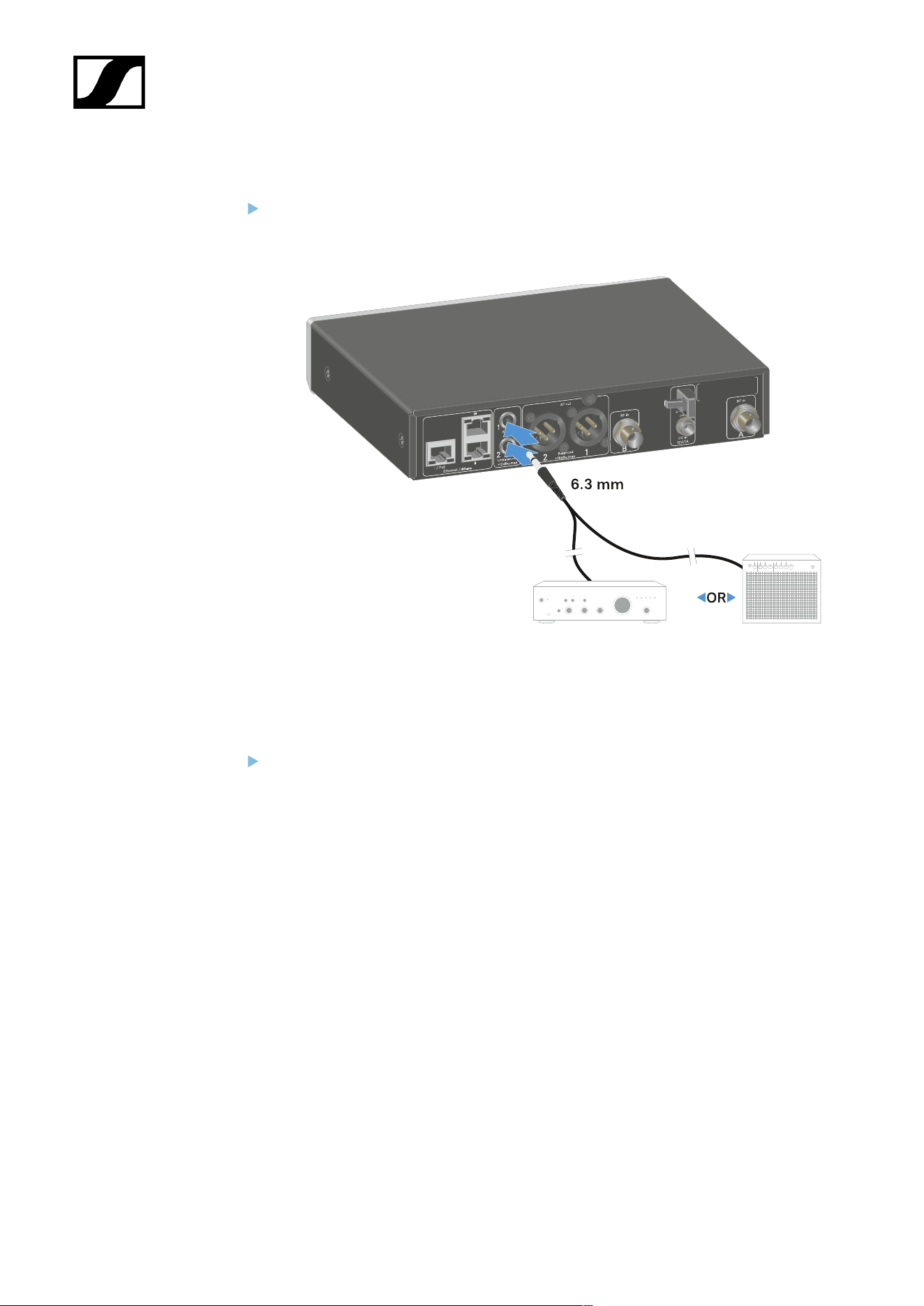

| 3 - Instruction manual
Installing receivers in a rack
Observe the following instructions when mounting the receiver in a rack.
The mounting brackets for installing the receiver in the rack can be found in the
packaging under the tray:
NOTICE
Rack mounting poses risks!
When installing the device in a closed 19" rack or multi-rack assembly,
please consider that, during operation, the ambient temperature, the
mechanical load and the electrical potentials will be different from those
of devices which are not mounted into a rack.
Make sure that the ambient temperature within the rack does
not exceed the permissible temperature limit stated in the
specifications. See Specifications.
Ensure sufficient ventilation; if necessary, provide additional
ventilation.
Make sure that the mechanical load of the rack is even.
When connecting to the power supply system, observe the
information indicated on the type plate. Avoid overloading the
circuits. If necessary, provide overcurrent protection.
When mounting in a rack, please note that intrinsically harmless
leakage currents of the individual power supply units may
accumulate, thereby exceeding the permissible limit value. As a
remedy, ground the rack via an additional ground connection.
224

| 3 - Instruction manual
Mounting a single receiver in a rack
Connect the mounting brackets to the sides of the receiver as shown.
Attach the front panel as shown.
If desired, attach the antennas to the front panel as shown. This requires the optional
AM 2 antenna front mount kit (see Accessories for rack mounting).
Mounting two receivers side by side in a rack
Place both receivers upside down and side by side on an even surface.
Tighten the jointing plate as shown.
225
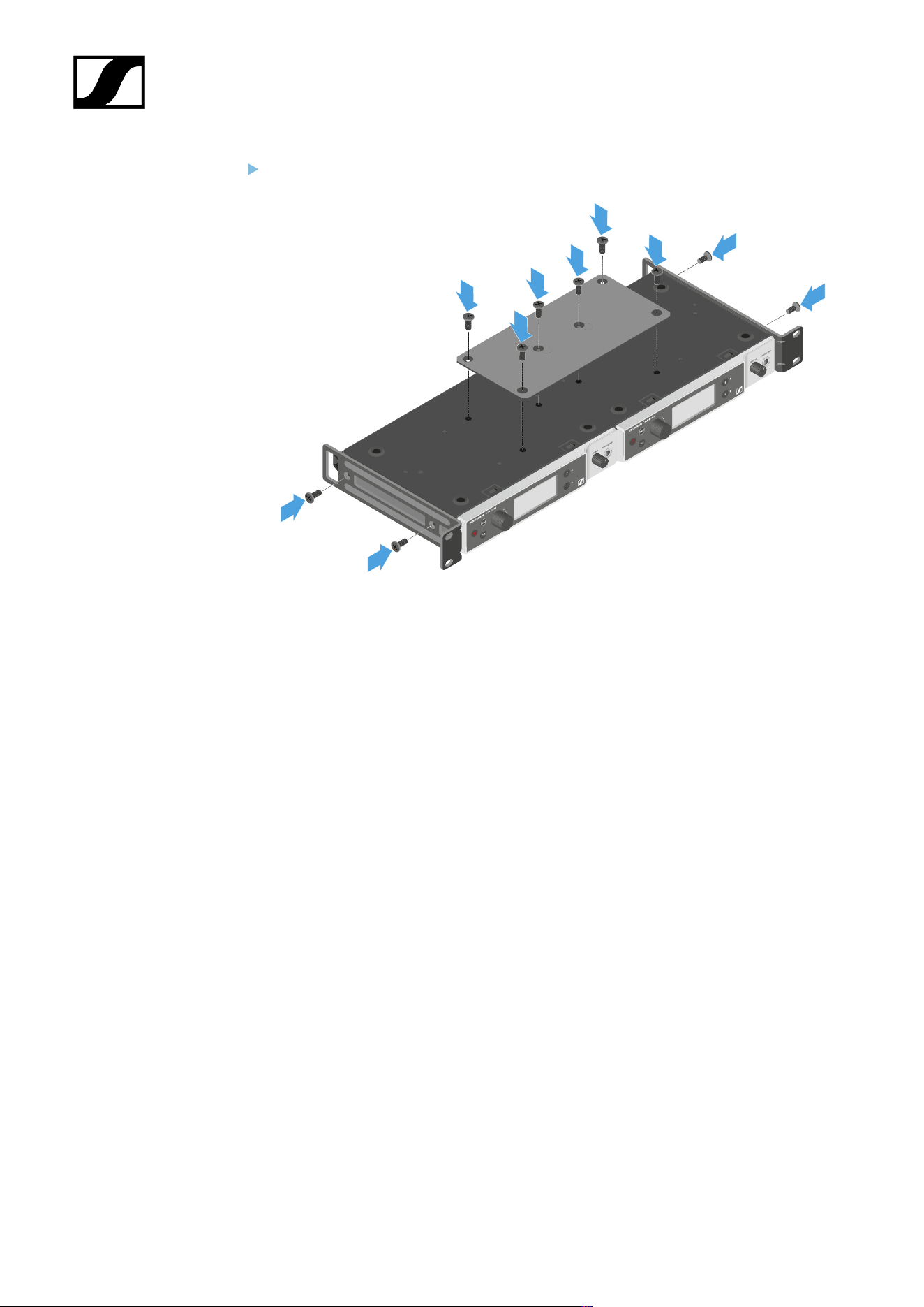
| 3 - Instruction manual
Attach the mounting brackets as shown.
226

| 3 - Instruction manual
Switching the receiver on and off
To switch the receiver on:
Short-press the ON/OFF button.
The receiver switches on.
To switch the receiver to standby mode:
If necessary, deactivate the lock-off function (see Lock-off function).
Hold down the ON/OFF button until the display switches off.
To switch the receiver off completely:
Disconnect the receiver from the power supply system by unplugging the power
supply unit from the wall socket or disconnecting the PoE connection.
227

| 3 - Instruction manual
Lock-off function
You can enable or disable the automatic lock-off function in the This Device -> Device Lock
menu item (see System -> This Device menu item).
To temporarily deactivate the lock-off function:
Press the jog dial.
Locked appears in the display panel.
Turn the jog dial.
Unlock? appears in the display panel.
Press the jog dial.
Lock-off function is now temporarily deactivated.
The lock-off function remains deactivated while you are actively working in the
operating menu.
After 10 seconds of inactivity, it automatically activates again.
228
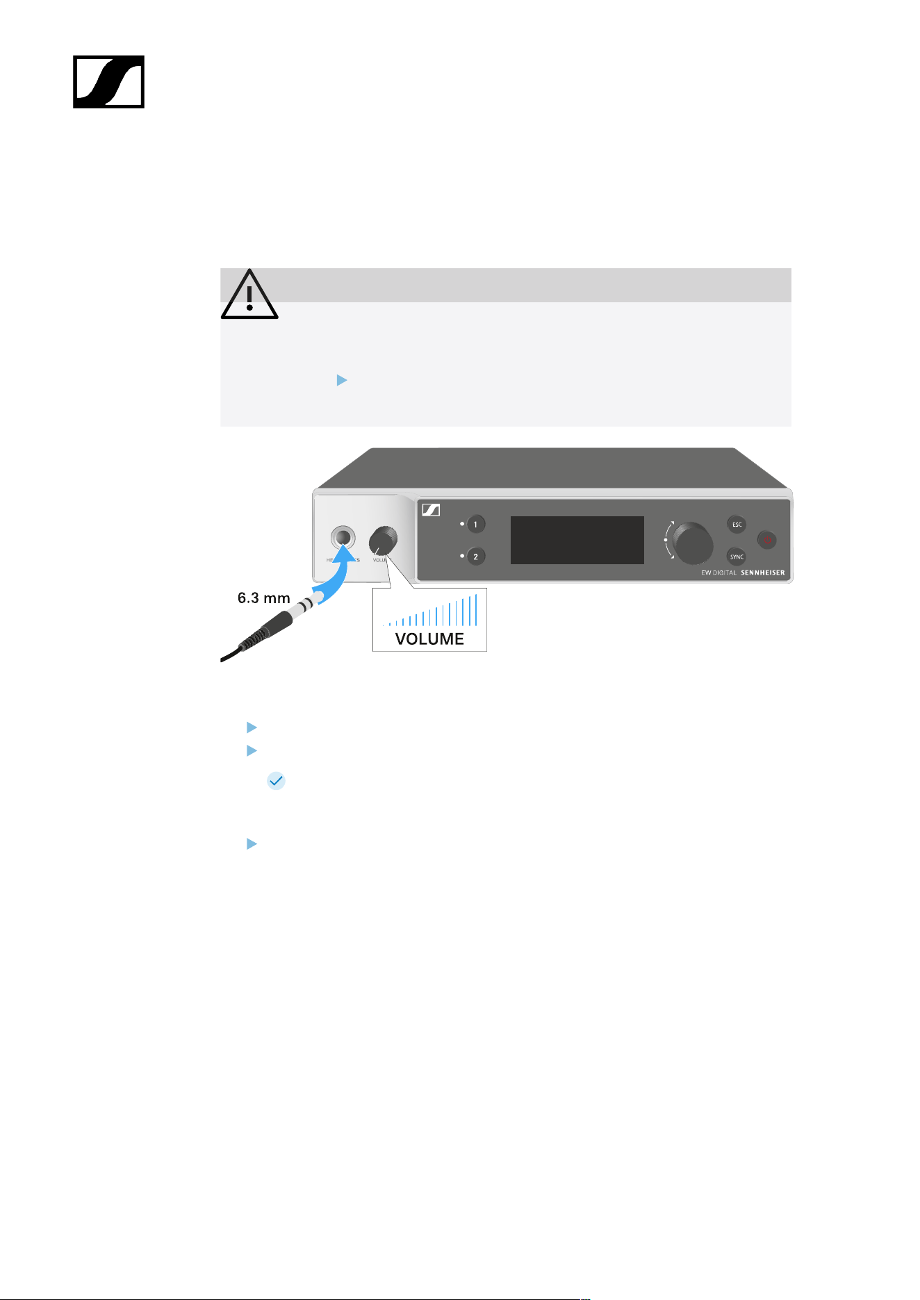
| 3 - Instruction manual
Using the headphone output
You can use the headphone output on the front of the receiver (6.3 mm jack) to listen to the
audio signals of the two channels.
CAUTION
Danger due to high volume levels
Volume levels that are too high may damage your hearing.
Turn down the volume of the headphone output before you put on
the headphone.
Connect the headphone to the headphone output.
Press the CH 1 or CH 2 button to listen to the audio signal from channel 1 or channel 2.
The headphone icon on the display indicates which channel is currently active
on the headphone output. By default, the signal from channel 1 is active on the
headphone output.
You can control the volume by turning the volume knob next to the headphone output.
229

| 3 - Instruction manual
Meaning of the LEDs
The two LEDs on the front of the receiver indicate the following information for channel 1 and
channel 2.
The LED is green:
• The link between the transmitter and receiving channel is
established.
• The audio signal is active.
The LED is yellow:
• The link between the transmitter and receiving channel is
established.
• The audio signal is muted.
or
• No microphone module is mounted on the handheld
transmitter.
The LED is flashing
yellow:
• The link between the transmitter and receiving channel is
established.
• The audio signal is overdriven (clipping).
The LED is
continuously red:
• The link between the transmitter and receiving channel is
established.
• The audio signal is overdriven (clipping).
230

| 3 - Instruction manual
The LED is flashing
red:
• The link between the transmitter and receiving channel is
established.
• The battery/rechargeable battery in the paired transmitter is
low.
The LED is flashing
blue:
• The Bluetooth Low Energy link is being established
between the receiver and a smartphone or tablet with the
Smart Assist app.
or
• The receiving channel is being synchronized with a
transmitter.
The LED is blue:
• The firmware is being updated.
231
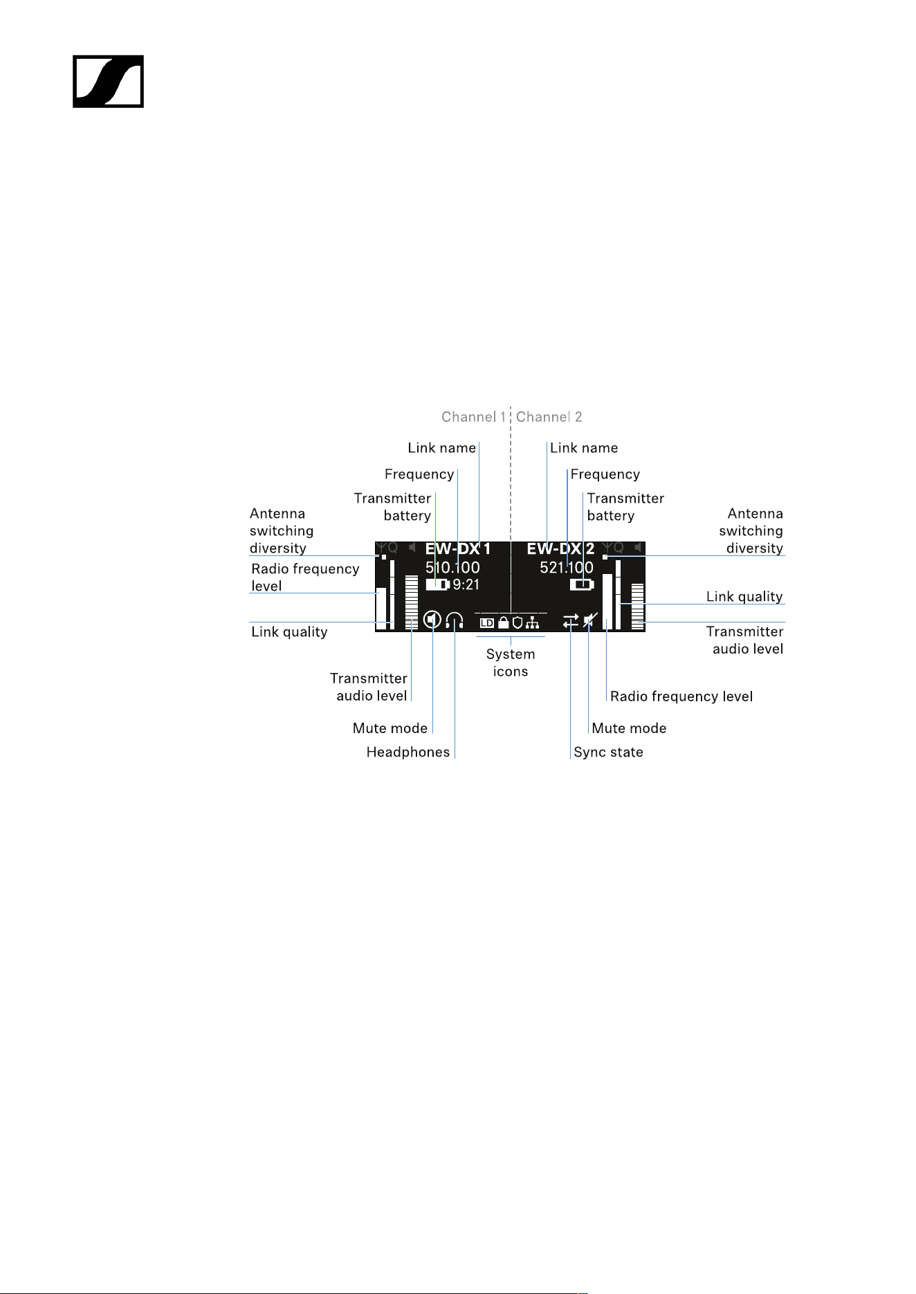
| 3 - Instruction manual
Displays on the receiver’s display panel
Status information such as frequency, reception quality, battery status and audio level is
shown on the display.
The display also shows the operating menu, which you can use to configure all of the settings
(see Buttons for navigating the menu).
Home screen
The home screen is the default view on the display. The following information for both
receiving channels is displayed here.
Antenna switching diversity:
Indicates which of the two antennas is currently active (left or right).
Signal level:
Displays the RF signal strength for the respective channel.
Link quality:
Displays the transmission quality for the respective channel.
232

| 3 - Instruction manual
On the one hand, the transmission quality depends on the field strength (RF
level indicator on the display). However, on the other hand, it also depends on
external sources of interference that cannot be identified on the RF level indicator
(for example, they may be on the same frequency or a very close neighboring
frequency or may not affect the field strength).
As a basic principle, a value significantly higher than 50% should be achieved
for a secure transmission.
Link name:
You can assign a name to the radio link in the receiver menu (see Ch 1 / Ch 2 -> Name menu
item).
Frequency:
You can set the frequency of the radio link manually or using the Auto-Setup function.
• See Ch 1 / Ch 2 -> Frequency menu item
• See Ch 1 / Ch 2 -> Scan / Auto Setup menu item
Transmitter audio level:
Displays the audio input level for the respective channel (see Ch 1 / Ch 2 -> Gain menu item).
This level is separate from the audio level that is output from the receiver (see Ch 1 / Ch 2 ->
AF Out menu item).
Transmitter battery:
Indicates the charging status of the transmitter’s BA 70 rechargeable battery or batteries.
When using the BA 70 rechargeable battery, the remaining runtime is also displayed in hours
and minutes.
Mute mode:
The mute switch is deactivated on the received transmitter.
The mute switch on the received transmitter is set to AF Mute and the audio
signal is muted.
• EW-DX SKM-S: Configuring mute mode and muting the handheld
transmitter (EW-DX SKM-S only)
• EW-DX SK: Configuring mute mode and muting the bodypack transmitter
Headphones:
233

| 3 - Instruction manual
The headphones icon indicates which channel is currently active on the
headphone output (see Using the headphone output).
Sync state:
This icon indicates that different values are set for the receiving channel of the
receiver and the transmitter. These values can be synchronized (see Connecting
to the EW-DX EM receivers / synchronizing the EW-DX EM).
System icons:
The LD icon is displayed when Link Density mode is activated. See System -> Link
Density menu item.
The lock icon is displayed when the Auto Lock function is enabled. See Lock-off
function.
The network icon appears when a network connection is successfully established.
See Connecting receivers in a network.
The shield icon is displayed when AES 256 encryption is enabled. See System ->
Link Encryption menu item.
Home screens 2 and 3
Turn the jog dial on the home screen to the right.
The second home screen appears with network information for the device.
Turn the jog dial to the right again.
The third home screen appears with information about the software and
hardware.
234

| 3 - Instruction manual
Meaning of the Link Quality Indicator
The LQI (Link Quality Indicator) on the display of the receiver shows the transmission
quality for the respective channel.
On the one hand, the transmission quality depends on the field strength (RF indicator on the
receiving channel display). However, on the other hand, it also depends on external sources
of interference that cannot be identified on the RF indicator (for example, they may be on the
same frequency or a very close neighboring frequency or may not affect the RF strength).
As a basic principle, an LQI value significantly higher than 50% should be achieved for a
secure transmission.
The LQI display shows the following information:
Green range from 50% to 100%:
• No transmission errors
The transmission quality is good enough to ensure an audio quality of 100%.
Yellow range from 20% to 49%:
• Individual transmission errors: short-term error correction active
• Individual audio artifacts may be audible
There are initial transmission errors. In rare cases, there are initial audible audio artifacts.
Error correction may be active in this case.
235

| 3 - Instruction manual
Orange range from 1% to 19%:
• Frequent transmission errors: long-term error correction active
• Risk of audio drop-outs
The transmission errors increase, which means that the error correction duration also
increases. There is a risk of audio drop-outs.
Red range 0%:
• No transmission
In this range, the transmission quality is so poor that audio drop-outs can no longer be
avoided.
236

| 3 - Instruction manual
Status messages
In certain situations, status messages may appear on the display.
AF Peak
The device is experiencing
repeated or prolonged audio
overload.
• Check the input signal on
the transmitter and adjust
it.
RF Peak
The antenna signal is
overmodulated.
• Increase the distance
between the receiving
antenna and the
transmitter.
Low Signal
The received signal is too low
or the transmission quality is
insufficient.
• Check that the antenna is
properly connected and
inspect the system wiring.
• Check that the transmitter
is within the reception
range.
• Check the orientation of the
receiver’s antenna.
Low Battery
The transmitter’s batteries or
rechargeable battery pack have
little battery life remaining (less
than 30 minutes).
• Replace the rechargeable
battery or batteries.
237

| 3 - Instruction manual
NoLink
No link to a transmitter.
• Verify that the transmitter is
on and within range.
• Check whether the
transmitter is muted (“RF
Mute” setting).
238
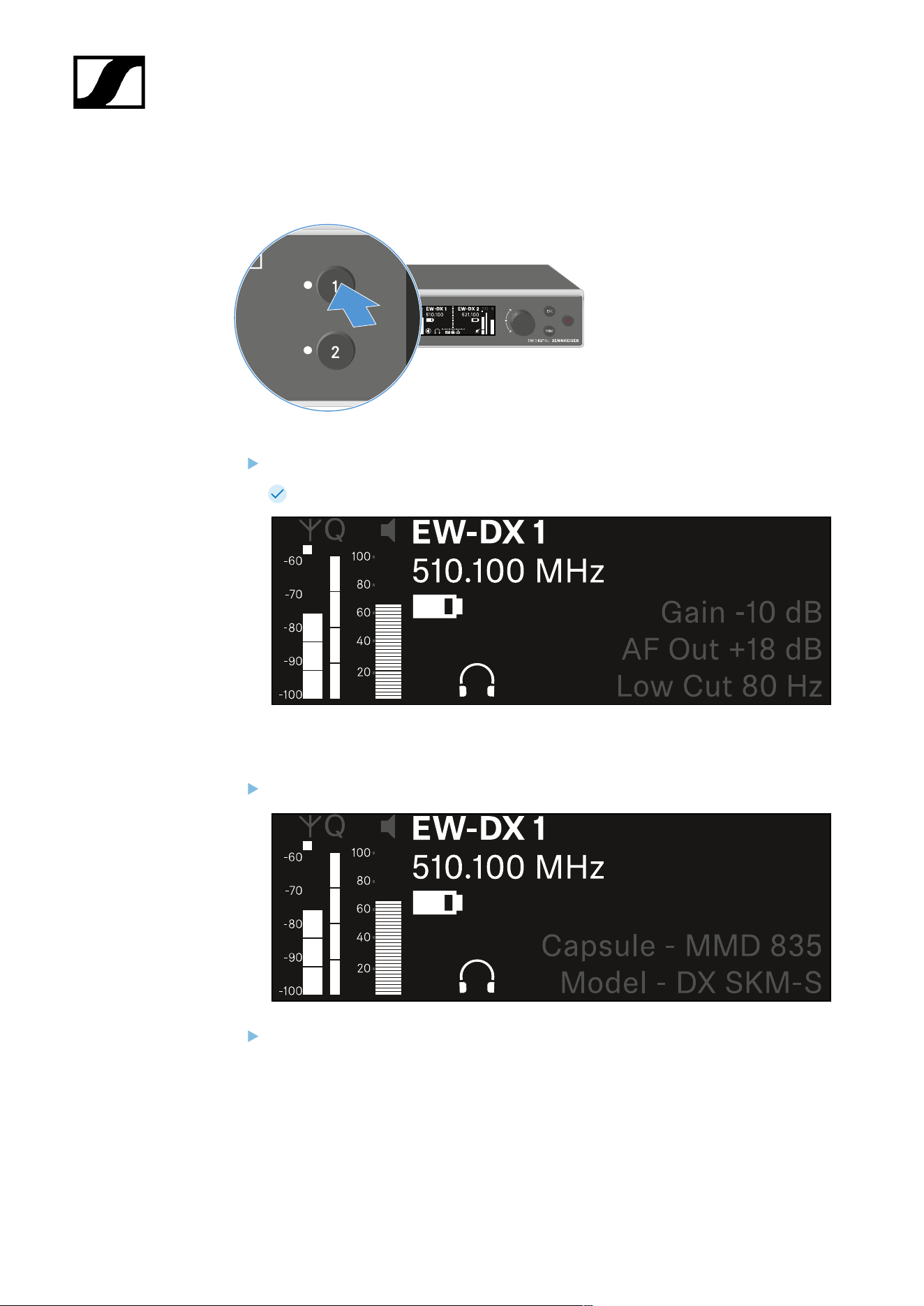
| 3 - Instruction manual
Channel 1
On the receiver’s home screen, press the CH 1 button.
The home screen for channel 1 appears.
In addition to the status information displayed on the home screen, information about
the channel’s audio settings is also displayed.
Turn the jog dial to the right to view more information about the received transmitter.
Turn the jog dial further to the right to mute or unmute the channel’s audio signal.
239

| 3 - Instruction manual
Press the jog dial to confirm your selection.
240
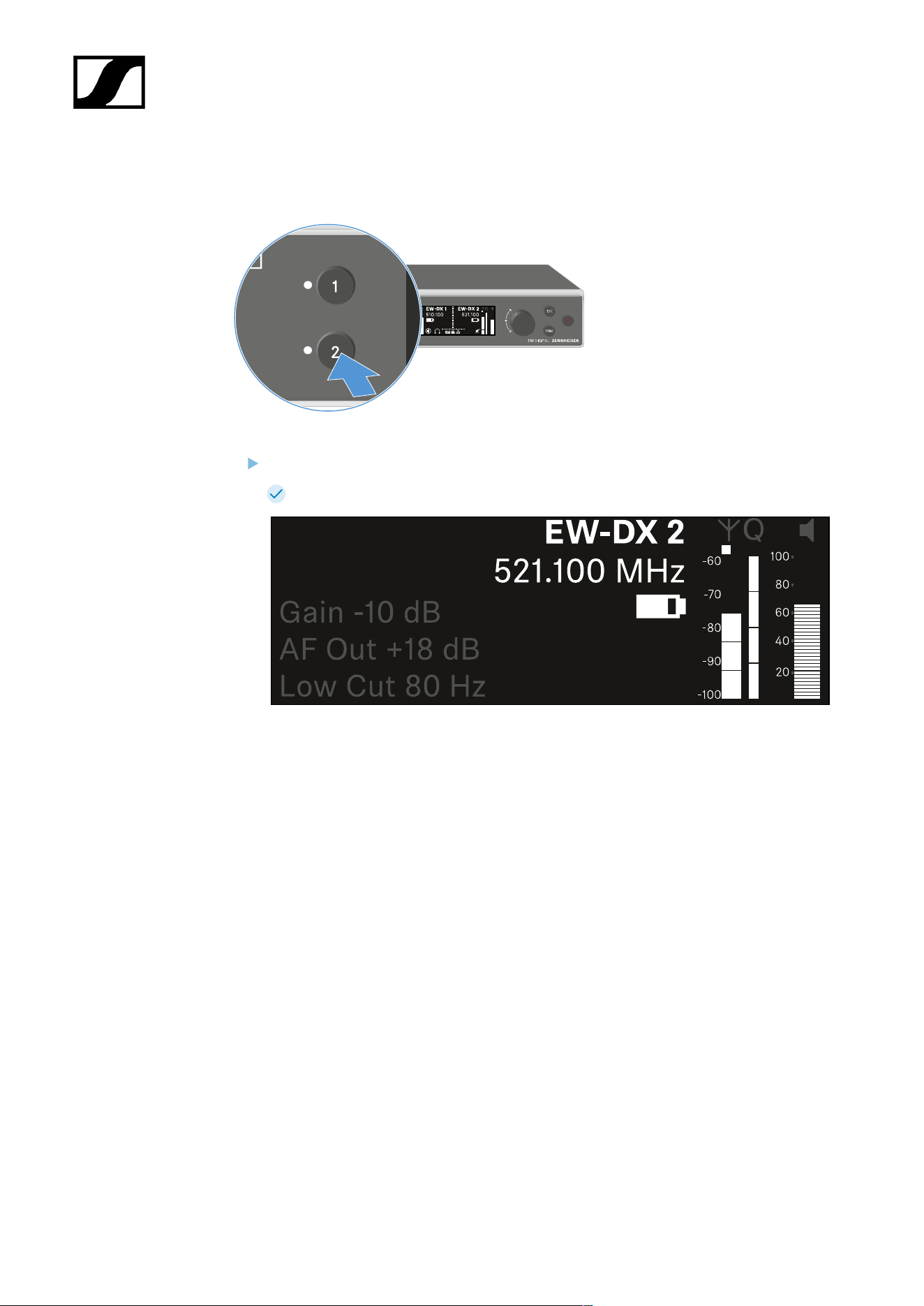
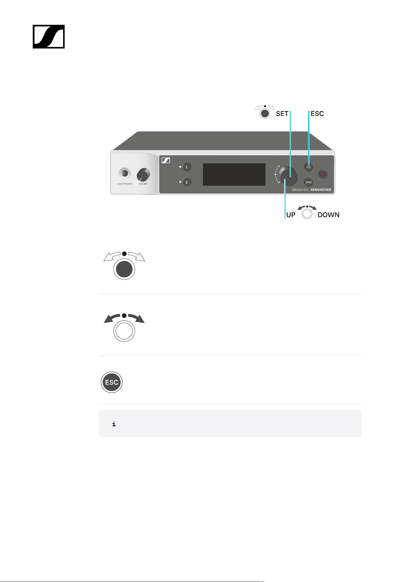
| 3 - Instruction manual
Buttons for navigating the menu
Use the following buttons to navigate through the receiver’s operating menu.
Press the jog dial
• Jumps from the home screen to the operating menu
• Calls up a menu item
• Changes to a submenu
• Saves settings
Turn the jog dial
• Selects a standard display (see Displays on the
receiver’s display panel)
• Changes to the previous or next menu item
• Changes the setting of a menu item
Press the ESC button
• Cancels the entry and returns to the previous display
Opening the menu and navigating the menu items
242

| 3 - Instruction manual
Opening the menu and navigating the menu items
To open the menu:
Press the jog dial when you are on the home screen.
Turn the jog dial to navigate to your desired menu item.
Press the jog dial to open the selected menu item.
To exit the menu:
Press the ESC button to exit the menu and return to the home screen.
Changes that were not previously saved by pressing the jog dial will be lost.
243

| 3 - Instruction manual
Menu structure
The figure shows the complete menu structure in an overview.
Version: firmware 3.0.0
244

| 3 - Instruction manual
Setting options in the menu
In the receiver menu, you can configure the following settings.
Changing the name of the radio link
• Ch 1 / Ch 2 -> Name menu item
Adjusting frequencies
• Ch 1 / Ch 2 -> Frequency menu item
Adjusting the gain of the wireless link
• Ch 1 / Ch 2 -> Gain menu item
Setting the output level of the audio signal
• Ch 1 / Ch 2 -> AF Out menu item
Adjusting the trim of the connected transmitter
• Ch 1 / Ch 2 -> Trim menu item
Adjusting the low-cut filter
• Ch 1 / Ch 2 -> Low Cut menu item
Configuring cable emulation for the bodypack transmitter
• Ch 1 / Ch 2 -> Cable Emul. menu item
Setting the function of the transmitter’s mute switch
• Ch 1 / Ch 2 -> Mute Mode menu item
Enabling the transmitter’s automatic lock-off function
• Ch 1 / Ch 2 -> Auto Lock menu item
Configuring the behavior of the transmitter’s LEDs
• Ch 1 / Ch 2 -> LED menu item
Activating/deactivating the parameters to be synchronized on the transmitters
• Ch 1 / Ch 2 -> Sync Parameters menu item
Performing a frequency scan and automatic frequency setup
• Ch 1 / Ch 2 -> Scan / Auto Setup menu item
245

| 3 - Instruction manual
Check the reception quality within the operating environment
• Ch 1 / Ch 2 -> Walktest menu item
Viewing the software version of the connected transmitters
• Ch 1 / Ch 2 -> TX Software menu item
Configuring different system settings
• Enabling AES 256 encryption
• Setting transmission mode
• Configuring network settings
• Updating the firmware for the transmitters
• Activating the Auto Setup function
• Changing device names
• System menu item
You can find an overview of the entire menu structure under Menu structure.
Ch 1 / Ch 2 -> Name menu item
In the Name menu item, you can define the name of the link for the channel in question.
This name is the name of the radio link between the transmitter and receiving
channel. You can set the name of the receiver as it will appear in a network from
the This Device menu in the system menu. See System -> This Device menu
item.
To open the Name menu item:
In the menu, navigate to the Name menu item for the desired channel.
Press the jog dial to open the menu.
246
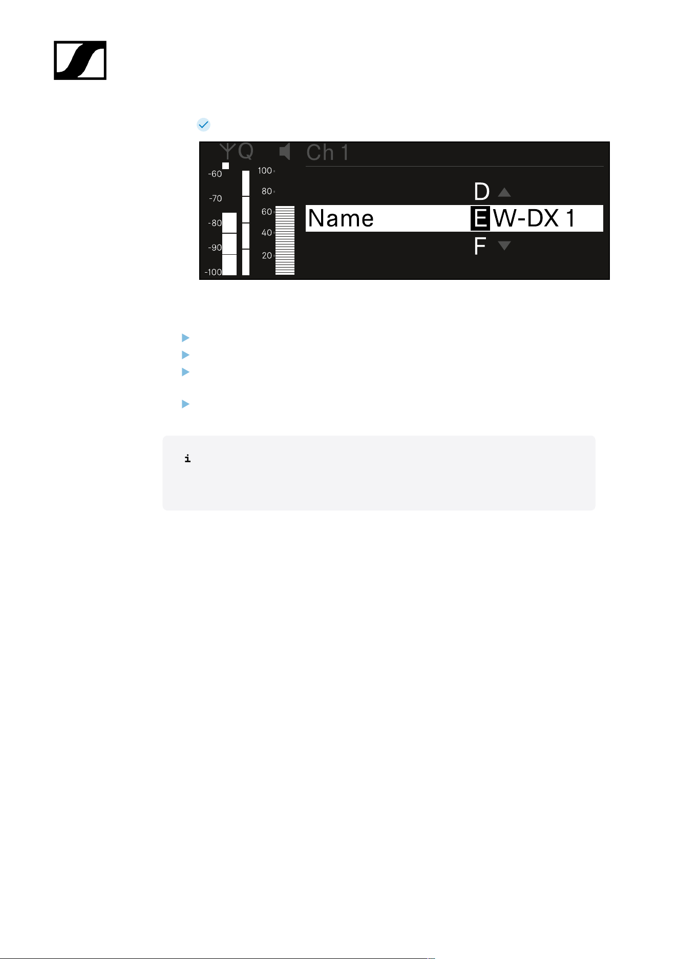
| 3 - Instruction manual
The following view is displayed:
To enter the desired link name:
Turn the jog dial to select the desired character.
Press the jog dial to go to the next position.
At the last position, press the jog dial to save the selected name.
Or
Press the ESC button to cancel the entry without saving the settings.
For the chosen link name to appear on the display of the received transmitter,
you must synchronize the channel (Connecting to the EW-DX EM receivers /
synchronizing the EW-DX EM).
247

| 3 - Instruction manual
Ch 1 / Ch 2 -> Frequency menu item
In the Frequency menu item, you can adjust the frequency for the channel in question.
You can select a frequency from the predefined list or set the frequency manually.
To open the Frequency menu item:
In the menu, navigate to the Frequency menu item for the desired channel.
Press the jog dial to open the menu.
The following view is displayed:
Rotate the jog dial to select between the List and Frequency subitems.
The List subitem allows you to select a frequency from the predefined list. The
Frequency subitem lets you set the desired frequency manually.
248

| 3 - Instruction manual
To select a frequency from a predefined list:
Open the List subitem.
Rotate the jog dial to choose between the predefined list (List Std) and the user-
defined list (List Usr).
You can create a custom list using the Wireless Systems Manager
(WSM) software and upload it to the receiver. For more information on
the WSM software, see:
sennheiser.com/wsm
Press the jog dial to confirm your selection.
Rotate the jog dial to select the desired channel from the list.
The frequency assigned to the channel is displayed.
Press the jog dial to save the selected channel.
Or
Press the ESC button to cancel the entry without saving the settings.
249
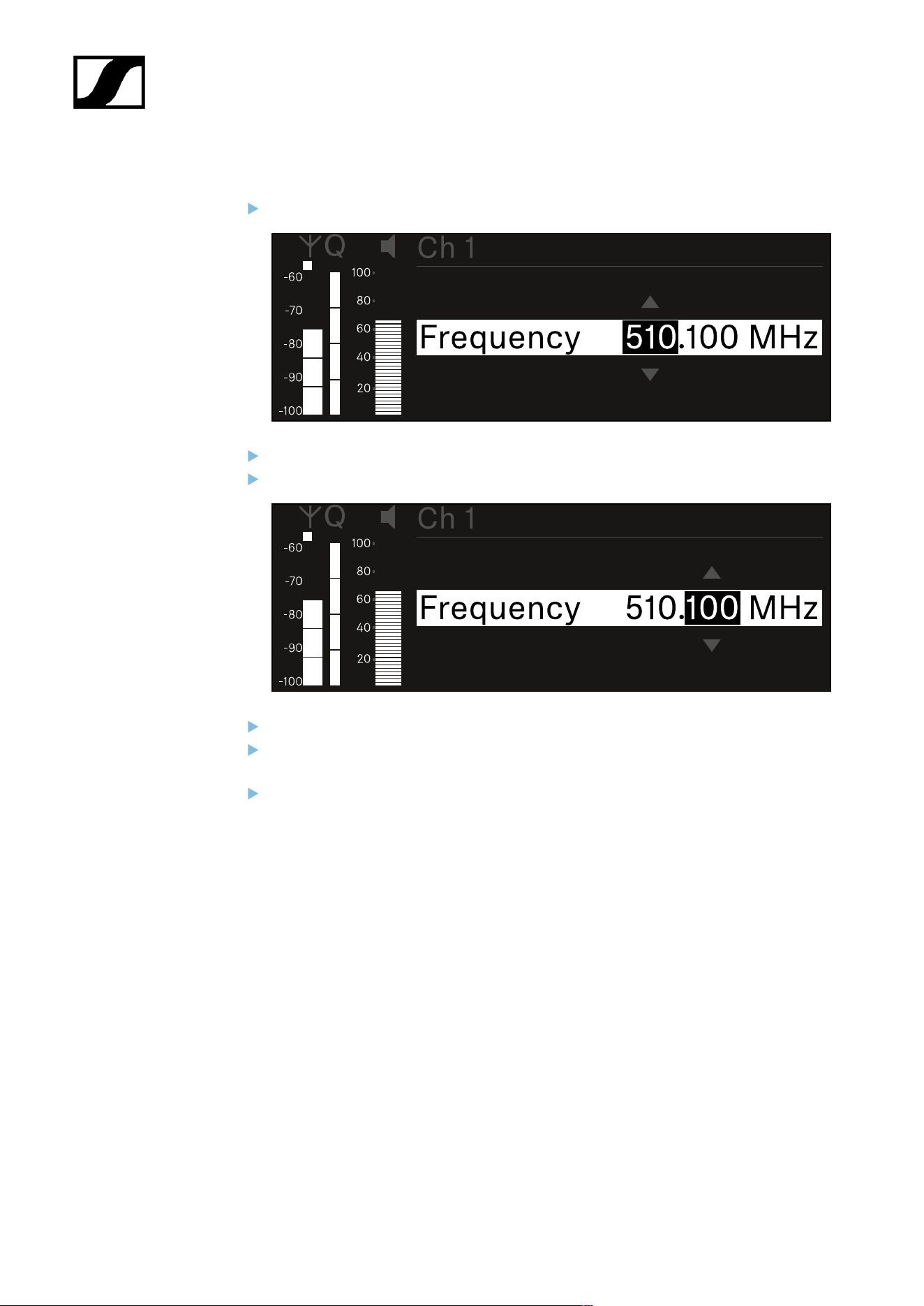
| 3 - Instruction manual
To set the frequency manually:
Open the Frequency subitem.
Turn the jog dial to set the MHz range for the frequency.
Press the jog dial to confirm your selection.
Turn the jog dial to set the kHz range for the frequency.
Press the jog dial to save your selected frequency.or
Or
Press the ESC button to cancel the entry without saving the settings.
250

| 3 - Instruction manual
Ch 1 / Ch 2 -> Gain menu item
Under the Gain menu item, you can set the audio level of the audio signal coming from the
received transmitter (e.g. vocals or speech via EW-DX SKM or guitar via EW-DX SK).
• Setting range: -3 dB to +42 dB in increments of 3 dB
To open the Gain menu item:
In the menu, navigate to the Gain menu item for the desired channel.
Press the jog dial to open the menu.
The following view is displayed:
Turn the jog dial to set the desired value.
Press the jog dial to save your setting.
Or
Press the ESC button to cancel the entry without saving the settings.
251

| 3 - Instruction manual
Ch 1 / Ch 2 -> AF Out menu item
In the AF Out menu item, you can set the audio level that is output via the audio outputs of
the particular receiving channel.
To open the AF Out menu item:
In the menu, navigate to the AF Out menu item for the desired channel.
Press the jog dial to open the menu.
The following view is displayed:
Turn the jog dial to set the desired value.
Press the jog dial to save your setting.
Or
Press the ESC button to cancel the entry without saving the settings.
252

| 3 - Instruction manual
Ch 1 / Ch 2 -> Trim menu item
In the Trim menu item, you can adjust the audio level of the received transmitter to input
signals of different volumes.
For example, if you are using multiple transmitters in alternation for a single
receiving channel, you can adjust the transmitters to the different input signals
using the trim setting. You do not need to change the channel’s gain setting.
• Setting range: -12 dB to +6 dB in increments of 1 dB
To open the Trim menu item:
In the menu, navigate to the Trim menu item for the desired channel.
Press the jog dial to open the menu.
The following view is displayed:
Turn the jog dial to set the desired value.
Press the jog dial to save your setting.
Or
Press the ESC button to cancel the entry without saving the settings.
253


| 3 - Instruction manual
Ch 1 / Ch 2 -> Low Cut menu item
In the Low Cut menu item, you can set the value of the low cut filter for the respective
channel.
Setting range:
• For EW-DX SK | EW-DX SK 3-PIN: Off, 30 Hz, 60 Hz, 80 Hz, 100 Hz, 120 Hz
• For EW-DX SKM | EW-DX SKM-S: 60 Hz, 80 Hz, 100 Hz, 120 Hz
To open the Low Cut menu item:
In the menu, navigate to the Low Cut menu item for the desired channel.
Press the jog dial to open the menu.
The following view is displayed:
Turn the jog dial to set the desired value.
Press the jog dial to save your setting.
Or
Press the ESC button to cancel the entry without saving the settings.
For the set value to be applied to the received transmitter, you must synchronize
the channel (Connecting to the EW-DX EM receivers / synchronizing the EW-
DX EM).
255
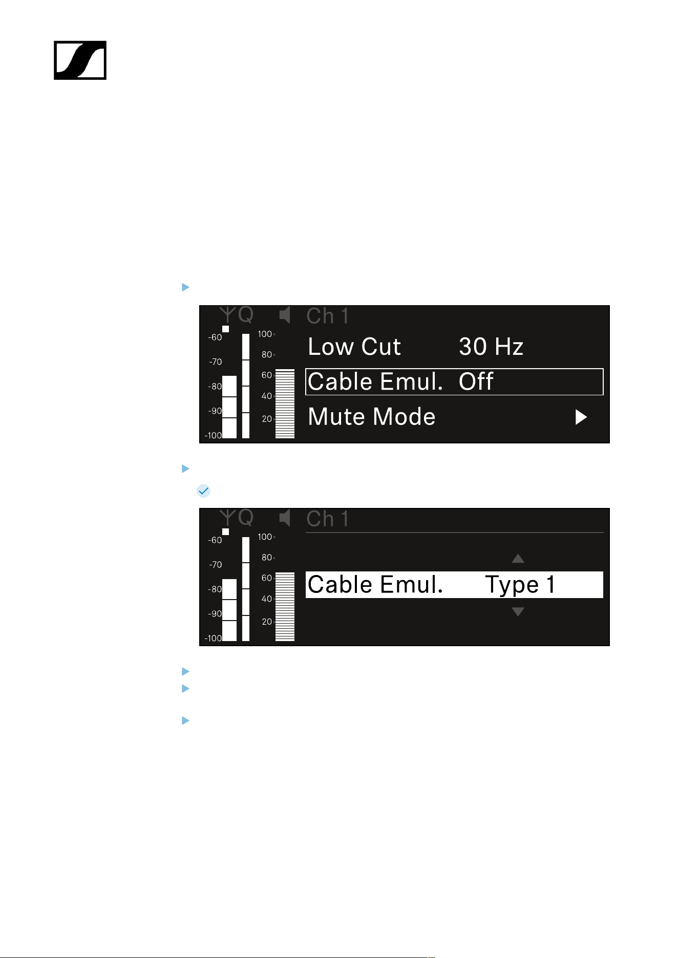
| 3 - Instruction manual
Ch 1 / Ch 2 -> Cable Emul. menu item
In the Cable Emul. menu item, you can emulate instrument cable lengths:
Setting range:
• Off, Type 1, Type 2, Type 3
To open the Cable Emul. menu item:
In the menu, navigate to the Cable Emul. menu item for the desired channel.
Press the jog dial to open the menu.
The following view is displayed:
Turn the jog dial to set the desired value.
Press the jog dial to save your setting.
Or
Press the ESC button to cancel the entry without saving the settings.
256

| 3 - Instruction manual
Ch 1 / Ch 2 -> Mute Mode menu item
In the Mute Mode menu item, you can set the function of the mute switch on the connected
transmitter (EW-DX SK, EW-DX SK 3-PIN, EW-DX SKM-S, EW-DX TS).
EW-DX SKM-S, EW-DX SK/EW-DX SK 3-PIN setting range:
• Disabled: The mute switch has no function.
• RF Mute: The RF signal is deactivated when the mute switch is on.
• AF Mute: The audio signal is muted when the mute switch is on.
EW-DX TS setting range:
• Disabled: The MUTE button has no function.
• AF Mute: The audio signal is muted when the MUTE button is pressed. Pressing the
button again activates the audio signal.
• PTT (Push to talk): Press and hold the MUTE button to activate the audio signal.
• PTM (Push to mute): Press and hold the MUTE button to mute the audio signal.
To open the Mute Mode menu item:
In the menu, navigate to the Mute Mode menu item for the desired channel.
Press the jog dial to open the menu.
The following view is displayed:
Turn the jog dial to set the desired value.
Press the jog dial to save your setting.
257

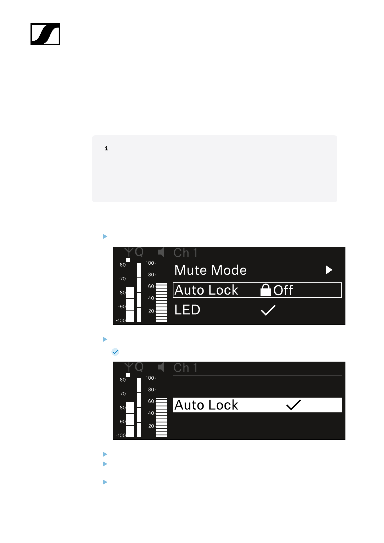
| 3 - Instruction manual
Ch 1 / Ch 2 -> Auto Lock menu item
In the Auto Lock menu item, you can activate or deactivate the lock-off for the received
transmitter.
The lock-off prevents the transmitter from being unintentionally switched off and also
prevents any changes to the transmitter’s menu.
If you want to change settings in the transmitter’s menu while the lock-off is
active, you have to temporarily disable the lock-off:
• EW-DX SKM: Lock-off function
• EW-DX SK: Lock-off function
To open the Auto Lock menu item:
In the menu, navigate to the Auto Lock menu item for the desired channel.
Press the jog dial to open the menu.
The following view is displayed:
Turn the jog dial to set the desired value.
Press the jog dial to save your setting.
Or
Press the ESC button to cancel the entry without saving the settings.
259


| 3 - Instruction manual
Ch 1 / Ch 2 -> LED menu item
The LED menu item allows you to set the behavior of the LINK LED on the received
transmitter.
Setting range:
• ON: The LINK LED remains continuously lit.
• OFF: The LINK LED switches off while the lock-off function is active.
For this to occur, the automatic lock-off function must be enabled in the Auto
Lock menu item (see Ch 1 / Ch 2 -> Auto Lock menu item).
To open the LED menu item:
In the menu, navigate to the LED menu item for the desired channel.
Press the jog dial to open the menu.
The following view is displayed:
Turn the jog dial to set the desired value.
Press the jog dial to save your setting.
Or
Press the ESC button to cancel the entry without saving the settings.
261


| 3 - Instruction manual
Ch 1 / Ch 2 -> Sync Parameters menu item
In the Sync Parameters menu item, you can choose which settings for the transmitter you
want to transfer from the receiver to the transmitter during the synchronization.
All of the settings can also be set separately in the menu on the transmitter.
During synchronization, the values set in the transmitter are overwritten with the
values set in the receiver.
The following parameters can be enabled or disabled for transmission.
• Name
• Frequency
• Trim
• Low Cut
• Cable Emul.
• Mute Mode
• Auto Lock
• LED
To open the Sync Settings menu item:
In the menu, navigate to the Sync Settings menu item for the desired channel.
Press the jog dial to open the menu.
The following view is displayed:
263
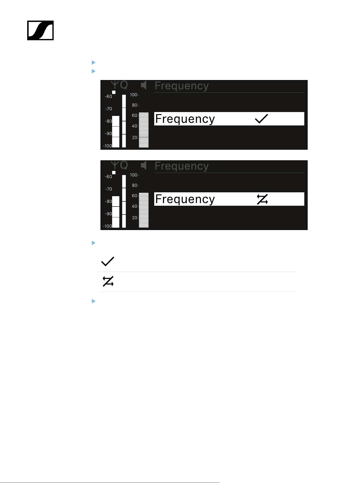
| 3 - Instruction manual
Turn the jog dial to choose between the options.
Press the jog dial to open your selected option.
For each option, select whether it will be synchronized or not.
The value set for this function will be transferred during synchronization.
The value set for this function will not be transferred during
synchronization.
Press the jog dial to save your setting.
264
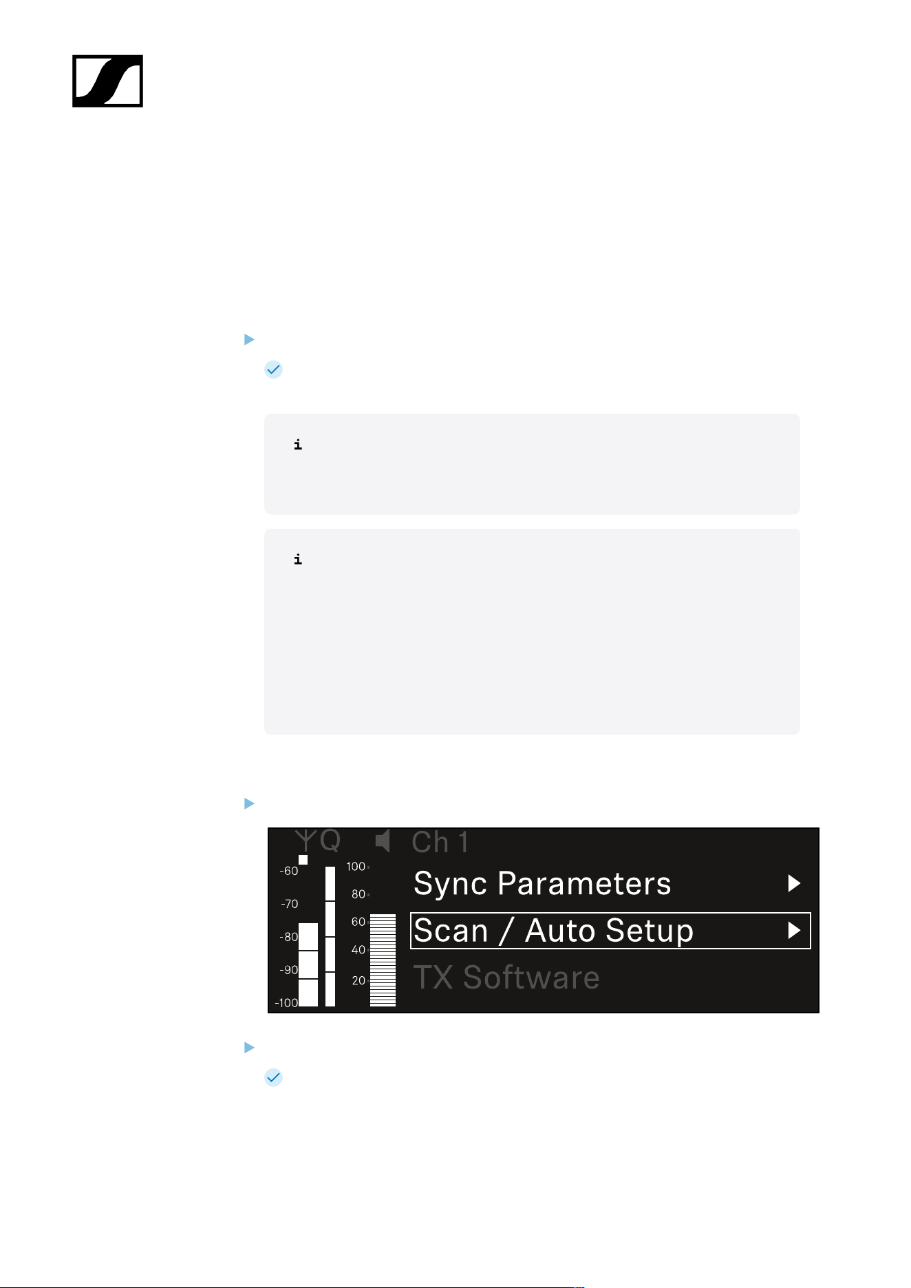
| 3 - Instruction manual
Ch 1 / Ch 2 -> Scan / Auto Setup menu item
The receiver lets you scan the frequency spectrum and display all of the free frequencies
in the selected frequency range. The automatic frequency setup can be used to distribute
the free frequencies to all of the EW-DX EM 2 Dante devices available in the network
automatically.
Switch off all transmitters before you perform the scan.
If transmitters are still switched on, they are detected as unavailable frequencies
and the frequencies that are actually available cannot then be used.
To perform the automatic frequency setup for all devices in the network,
the Auto Setup function must be enabled in the receiver’s system menu:
System -> Auto Setup menu item
An EM that is performing one of the following actions will be excluded
from the frequency setup of another EM:
• Remote (full) scan
• Scan Me / Scan Network -> Autosetup
• Bonding
• TX Sync
• TX Update
• Device Update (if in progress)
To open the Scan / Auto Setup menu item:
In the menu, navigate to the Scan / Auto Setup menu item for the desired channel.
Press the jog dial to open the menu.
The following view is displayed:
265
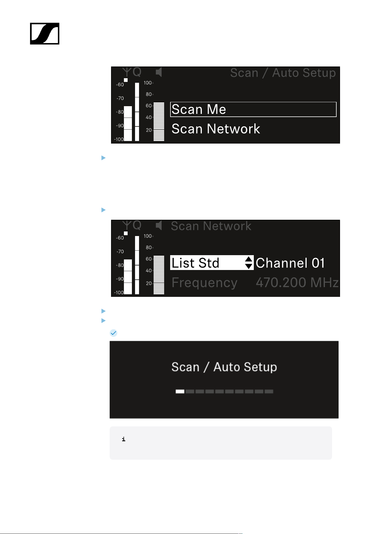
| 3 - Instruction manual
Turn the jog dial to choose between the Scan Me and Scan Network options.
• Scan Me: The frequency scan and the frequency setup are performed only for
the selected receiving channel.
• Scan Network: The frequency scan and the frequency setup are performed for
both channels of the receiver as well as for all other receivers available in the
network.
Press the jog dial to open your selected option.
Select a frequency from which to start the scan.
Press the jog dial to start the scan.
The spectrum is scanned for free frequencies above the selected frequency.
After the scan free frequencies are displayed, which you can then assign
to the channels.
266
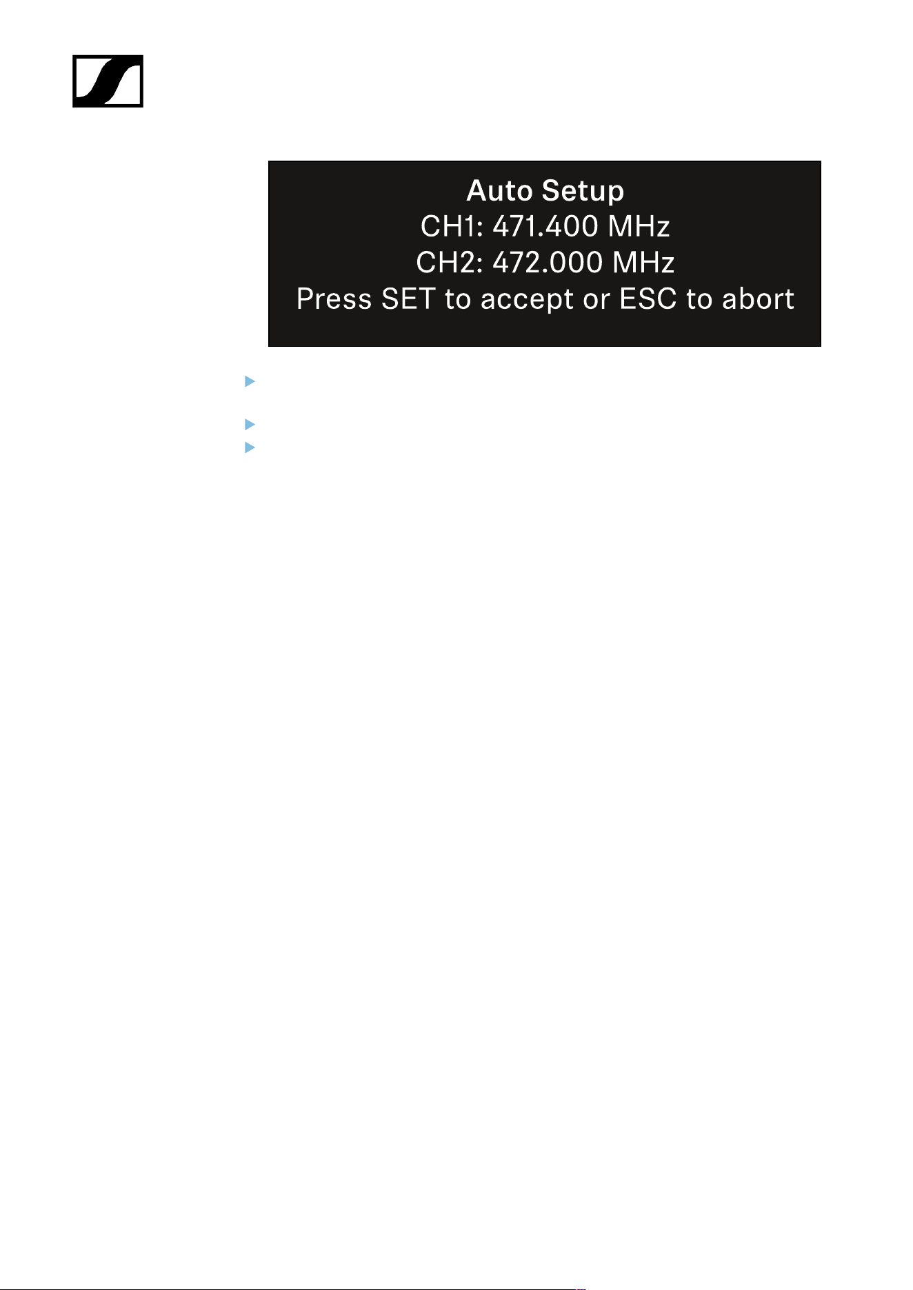
| 3 - Instruction manual
Press the jog dial to assign the free frequencies to the receiving channels.
Or
Press the ESC key to cancel and not assign new frequencies.
Next, synchronize the receiving channels with the corresponding transmitters to
establish the radio link at the new selected frequencies (Synchronizing the receiver
and transmitter).
267

| 3 - Instruction manual
Ch 1 / Ch 2 -> Walktest menu item
The Walktest menu item allows the performance of a reception test.
Once you have set up and installed all of the receivers and transmitters for your event, we
recommend performing a walk test. This lets you check whether sufficient reception strength
is available throughout the entire area used.
Start the walktest function in this menu item and then walk the entire area with one
transmitter. The results of the walk test give you information about the reception quality.
Opening the Walktest menu item
In the menu, navigate to the Walktest menu item for the desired channel.
Press the jog dial to open the menu.
The following view is displayed:
To start the reception test:
Press the jog dial.
Walk the entire area on which you want to operate the system with the transmitter.
The following values are recorded on the display:
• RF: Reception from antenna in dBm
• LQI: Connection quality as a %, see Meaning of the Link Quality Indicator
• AF: Transmitter audio frequency in dBFS
268
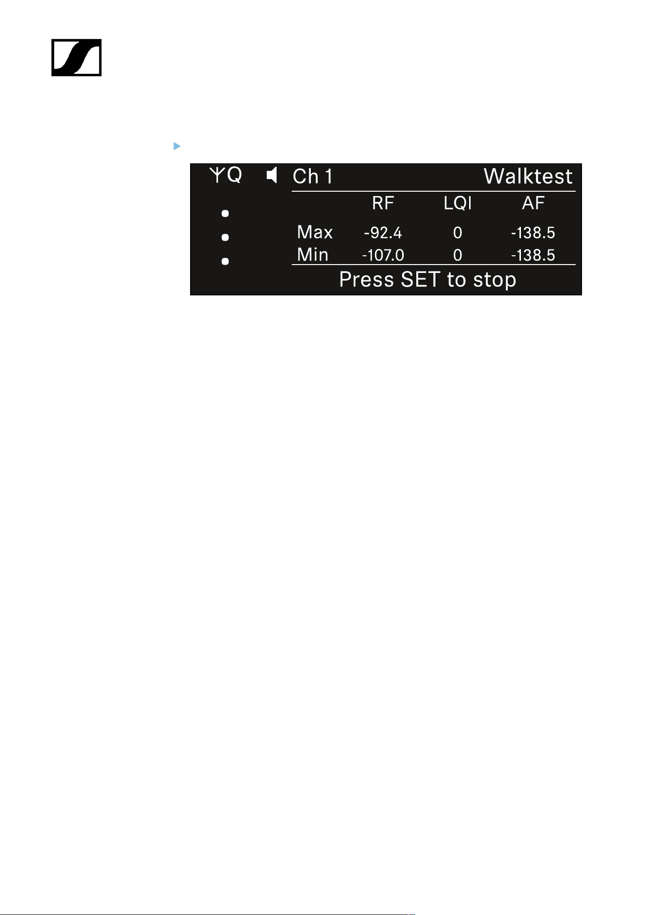
| 3 - Instruction manual
To end the reception test:
Press the Jog-Dial to finish the walk test when you are ready.
269

| 3 - Instruction manual
Ch 1 / Ch 2 -> TX Software menu item
The TX Software menu item displays the software version of the received transmitter.
You cannot open this menu item to make settings.
In the menu, navigate to the TX Software menu item for the desired channel.
The version number of the transmitter software is shown on the display. The
transmitter must be switched on for this to be displayed.
You can find information about updating the transmitter firmware in section
System -> TX Update menu item.
270

| 3 - Instruction manual
System menu item
In the System menu, you can make system-wide settings that will affect the entire device and
not only the respective receiving channel.
The following menu items are available:
Link Encryption
• This menu item lets you secure the radio link with AES 256 encryption.
• System -> Link Encryption menu item
Link Density
• In this menu item, you can set the required transmission mode.
• System -> Link Density menu item
Network
• In this menu item, you can configure the settings for the network connection.
• System -> Network menu item
TX Update
• This menu item lets you perform a firmware update for the transmitters.
• System -> TX Update menu item
Auto Setup
• This menu item allows you to activate automatic frequency setup for the receiver.
• System -> Auto Setup menu item
This Device
• This menu item allows you to enter a device name and display information about the
receiver’s hardware and software.
• System -> This Device menu item
System -> Link Encryption menu item
You can secure the radio link between the transmitter and receiver using AES 256
encryption.
271

| 3 - Instruction manual
To open the Link Encryption menu item:
In the System menu, navigate to the Link Encryption menu item.
Press the jog dial to open the menu.
The following view is displayed:
Turn the jog dial to choose between the On and Off options.
Press the jog dial to save your setting.
After enabling AES 256 encryption, the connected transmitter must be
resynchronized with the receiver to enable encryption on the transmitter as well.
272
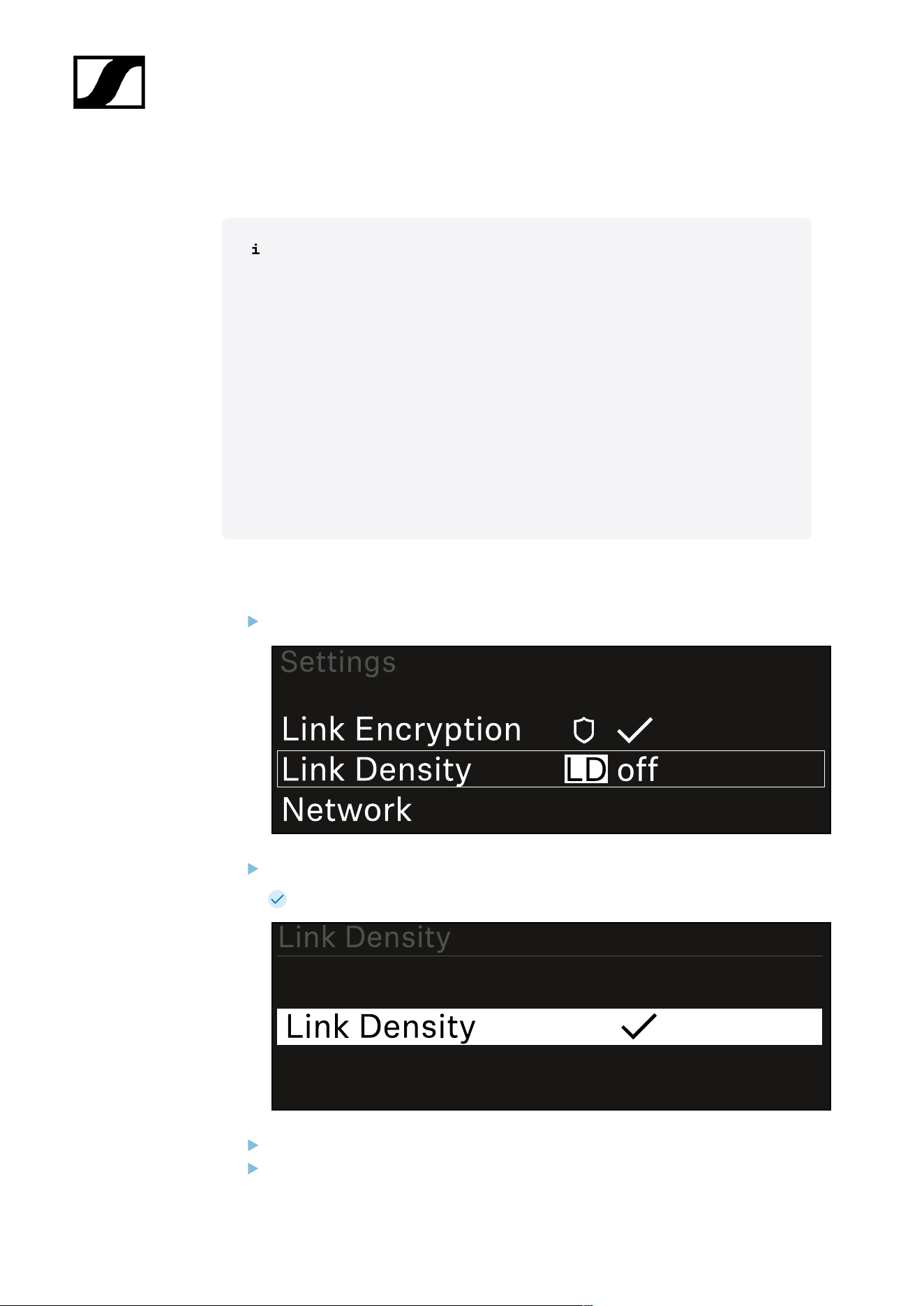
| 3 - Instruction manual
System -> Link Density menu item
Link Density mode (LD mode)
LD mode doubles the number of usable carrier frequencies in the available
spectrum, as the minimum distance for the equidistant frequency grid is halved.
This is achieved by reducing the modulation bandwidth of the transmitter. This
means that a much smaller frequency spacing between neighboring frequencies
can be selected, and therefore more frequencies can be used in the same
available spectrum without intermodulation.
LD mode is recommended if the following criteria are met:
• The required number of channels cannot be achieved using the normal
mode, as there may be only a small spectrum available.
• The distance between the transmitters and the antennas is not too great.
To open the Link Density menu item:
In the System menu, navigate to the Link Density menu item.
Press the jog dial to open the menu.
The following view is displayed:
Turn the jog dial to choose between the On and Off options.
Press the jog dial to save your setting.
273

| 3 - Instruction manual
If you have enabled LD mode, the receiver must be restarted.
Press the jog dial to restart the receiver.
Or
Press the ESC button to cancel the mode change.
After enabling LD mode and restarting the receiver, the connected transmitter
must be resynchronized with the receiver to enable LD mode on the transmitter
as well.
274
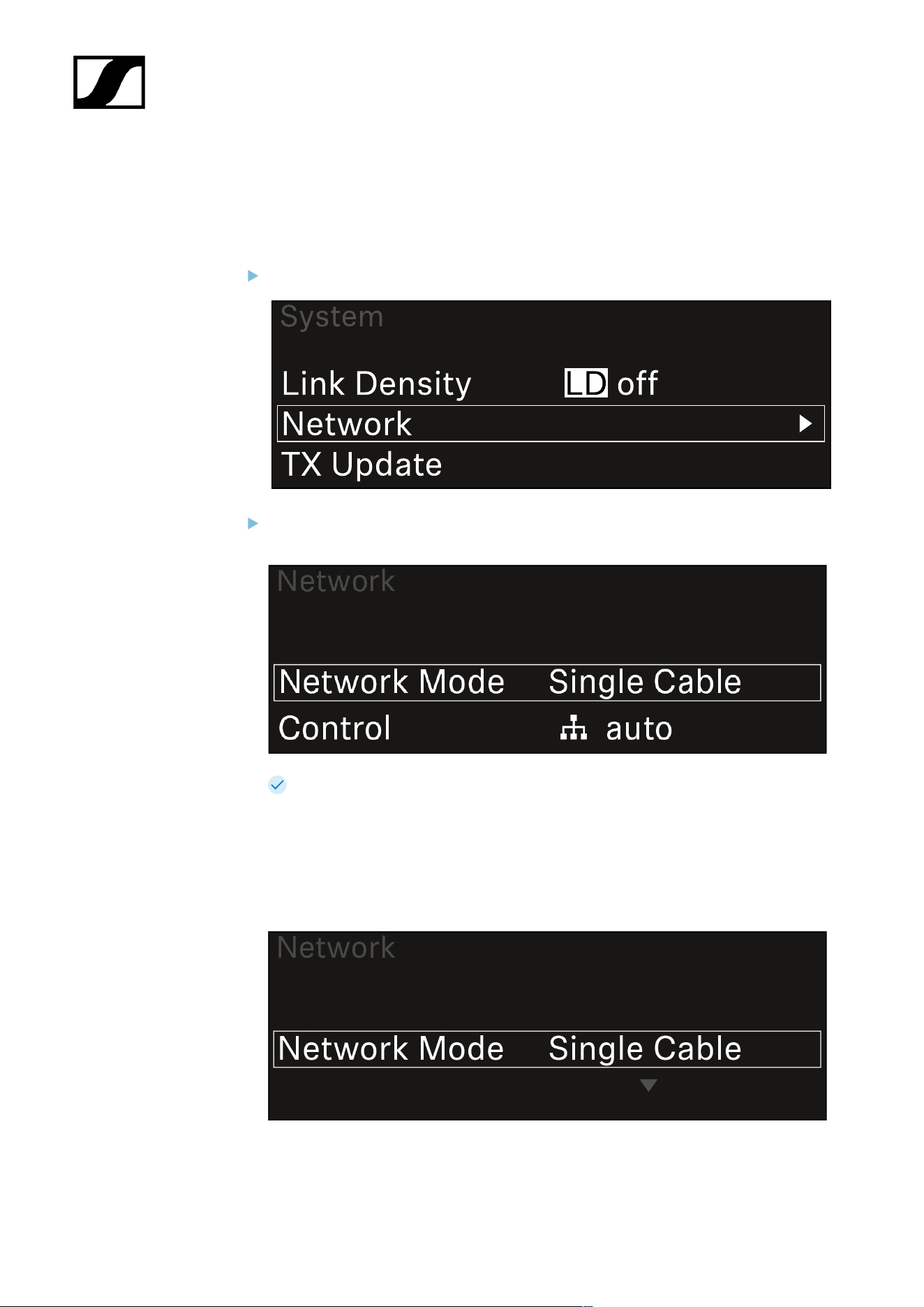
| 3 - Instruction manual
System -> Network menu item
In this menu item, you can configure the settings for the network connection.
To open the Network menu item:
In the System menu, navigate to the Network menu item.
Rotate the jog dial to navigate through the Network menu and select the desired
menu item.
You can make the following settings here:
Network Mode
• Single Cable
• Split 1
• Split 2
• Redundancy
275

| 3 - Instruction manual
See Connecting receivers in a Dante® network.
Control
• Mode
• Auto: The network configuration is performed automatically.
• Manual: The network configuration can be performed manually.
• mDNS
• You can enable or disable this option if you want to use mDNS for
automatic device detection in the network.
• IP
• If the Mode option is set to Auto, the automatically assigned IP
address is displayed here.
• If the Mode option is set to Manual, you can set the IP address here.
• Netmask
• If the Mode option is set to Auto, the automatically assigned netmask
is displayed here.
• If the Mode option is set to Manual, you can set the netmask here.
• Gateway
• If the Mode option is set to Auto, the automatically assigned gateway
is displayed here.
• If the Mode option is set to Manual, you can set the gateway here.
Dante - Dante Primary and Dante Secondary
• Mode
• Auto: The network configuration is performed automatically.
• Manual: The network configuration can be performed manually.
• mDNS
• You can enable or disable this option if you want to use mDNS for
automatic device detection in the network.
• IP
• If the Mode option is set to Auto, the automatically assigned IP
address is displayed here.
• If the Mode option is set to Manual, you can set the IP address here.
• Netmask
• If the Mode option is set to Auto, the automatically assigned netmask
is displayed here.
• If the Mode option is set to Manual, you can set the netmask here.
• Gateway
• If the Mode option is set to Auto, the automatically assigned gateway
is displayed here.
• If the Mode option is set to Manual, you can set the gateway here.
276

| 3 - Instruction manual
Spanning Tree (STP)
• If the option is enabled, misconfigurations between network modes and
cabling is avoided.
• If the option is disabled, broadcast storms may result.
• By default and after a factory reset, STP is enabled.
The Spanning Tree is configured with a priority of 57344 and should be
considered when setting up a network with managed switch so that an
EW-DX EM doesn't get the route bridge.
To save the settings you have made:
Turn the jog dial until Apply appears in the selection frame.
Press the jog dial to save your settings.
277

| 3 - Instruction manual
System -> TX Update menu item
This menu item lets you perform a firmware update for the transmitters. This update is
recommended after you perform a firmware update for the receiver (see Updating the
firmware of the receiver).
The firmware versions currently installed on the connected transmitter can be
viewed under the TX Software menu item for the respective channel (see Ch 1 /
Ch 2 -> TX Software menu item).
To open the TX Update menu item:
In the System menu, navigate to the TX Update menu item.
Press the jog dial to open the menu.
The available sender firmware is displayed:
Press the jog dial to start the firmware update.
278

| 3 - Instruction manual
Press the SYNC button on the connected transmitter for 3 seconds.
You have about 20 seconds to do this. The progress bar shows the remaining
time.
The system carries out the firmware update for the transmitter.
The progress of the update is shown on the receiver’s display.
The transmitter’s display shows that the firmware update is in progress.
279

| 3 - Instruction manual
NOTICE
Canceling the update can impair the function of the transmitter
If the transmitter is turned off during the firmware update, the update
may fail and the transmitter may cease to function correctly.
Do not turn off the transmitter during the update.
Do not remove the batteries or rechargeable battery pack during
the update.
Make sure that the transmitter’s (rechargeable) batteries are
sufficiently charged before updating.
280

| 3 - Instruction manual
System -> Auto Setup menu item
In this menu item, you can activate the Auto Setup function for the receiver.
If the function is activated here, you can perform an automatic frequency setup for both
channels of this receiver via the Scan / Auto Setup menu item.
See Ch 1 / Ch 2 -> Scan / Auto Setup menu item.
The receiver will also be enabled for automatic frequency setup in a network consisting of
multiple receivers.
If the function is disabled here, you can only assign a frequency to the selected channel of
the receiver via the Scan / Auto Setup menu item.
To open the Auto Setup menu item:
In the System menu, navigate to the Auto Setup menu item.
Press the jog dial to open the menu.
The following view is displayed:
Turn the jog dial to choose between the On and Off options.
Press the jog dial to save your setting.
281
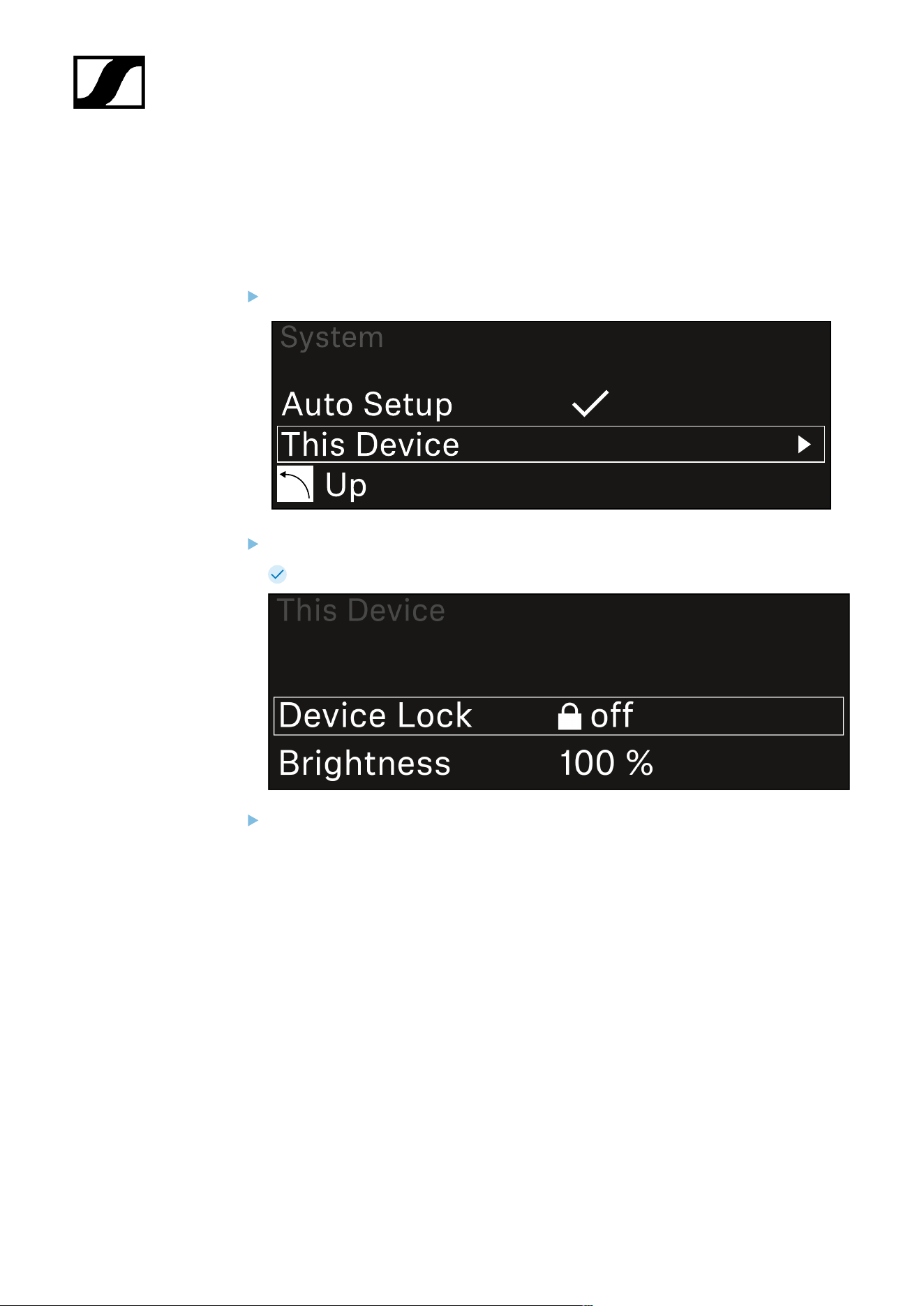
| 3 - Instruction manual
System -> This Device menu item
This menu item allows you to change the device name, view software and hardware
information, or reset the device to factory settings.
To open the This Device menu item:
In the System menu, navigate to the This Device menu item.
Press the jog dial to open the menu.
The following view is displayed:
Choose from the following:
• Device Lock: Set the lock-off of the receiver.
• Brightness: Set the brightness of the display.
• Device Name: Open this menu item to change the device name. This receiver
will be displayed in the network under this name.
• MAC: Shows the MAC address of the receiver.
• Dante Name: Shows the name of the device in the Dante network.
• Dante Pri MAC/Dante Sec MAC: Shows the primary/secondary Dante MAC
address of the receiver
• Software: Shows the software version of the receiver.
• HW Main/HW Front/HW Tuner1/HW Tuner 2/HW Interface: Displays the
hardware versions of the boards installed in the receiver.
282

| 3 - Instruction manual
• Reset:
• Audio Ch1 | Audio Ch2 | Audio All (EW-DX EM 2 / EW-DX EM 2
Dante): resets selected audio channel settings or all audio channel
settings to their default.
• Audio Ch1 | Audio Ch2 | Audio Ch3 | Audio Ch4 | Audio All (EW-
DX EM 4 Dante): resets selected audio channel settings or all audio
channel settings to their default.
• Network: resets the network settings and the claiming password to
their factory settings.
• Factory: resets the receiver to factory settings.
283

| 3 - Instruction manual
Updating the firmware of the receiver
You can update the receiver firmware using the Sennheiser Control Cockpit software, the
Wireless Systems Manager software or the Smart Assist app.
Updating with the Sennheiser Control Cockpit or the Wireless Systems Manager:
Connect the receiver to a network (see Connecting receivers in a network) and
establish the connection with the software.
For more information about controlling devices with the Sennheiser
Control Cockpit or Wireless Systems Manager software, refer to the
software help.
You can download the software here:
sennheiser.com/scc
sennheiser.com/wsm
To update the transmitter’s firmware, go to System -> TX Update in the
menu on the receiver. See System -> TX Update menu item
Updating with the Smart Assist app:
Connect the receiver to a network (see Connecting receivers in a network).
Connect a wireless access point to the network.
Connect your smartphone to this network.
Start the update process in the Smart Assist app:
Click on “Update” if the device is on the network.
Follow the instructions.
Or
Search for devices that can be updated.
Follow the instructions.
284
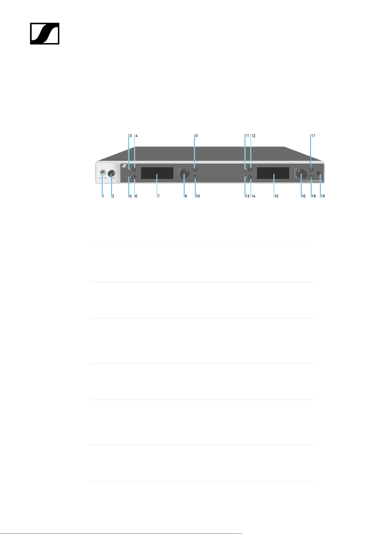
| 3 - Instruction manual
EW-DX EM 4 Dante rack receiver
Product overview
Front
1 Headphone socket
• See Using the headphone output
2 Volume control for the headphone socket
• See Using the headphone output
3 CH 1 LED to indicate the status of channel 1
• See Meaning of the LEDs
4 CH 1 button for selecting channel 1
• See Displays on the receiver’s display panel
• See Buttons for navigating the menu
5 CH 2 LED to indicate the status of channel 2
• See Meaning of the LEDs
6 CH 2 button for selecting channel 2
• See Displays on the receiver’s display panel
• See Buttons for navigating the menu
7 Display for status information and operating menu
• See Displays on the receiver’s display panel
285

| 3 - Instruction manual
8 Jog dial (UP/DOWN/SET) for navigating the operating menu
• See Buttons for navigating the menu
9 ESC button for canceling an action in the menu
• See Buttons for navigating the menu
10 SYNC button for synchronizing the transmitter and receiver
• See Establishing a radio link | Synchronizing the receiver and
transmitter
11 CH 3 LED to indicate the status of channel 3
• See Meaning of the LEDs
12 CH 3 button for selecting channel 3
• See Displays on the receiver’s display panel
• See Buttons for navigating the menu
13 CH 4 LED to indicate the status of channel 4
• See Meaning of the LEDs
14 CH 4 button for selecting channel 4
• See Displays on the receiver’s display panel
• See Buttons for navigating the menu
15 Display for status information and operating menu
• See Displays on the receiver’s display panel
16 Jog dial (UP/DOWN/SET) for navigating the operating menu
• See Buttons for navigating the menu
17 ESC button for canceling an action in the menu
• See Buttons for navigating the menu
286
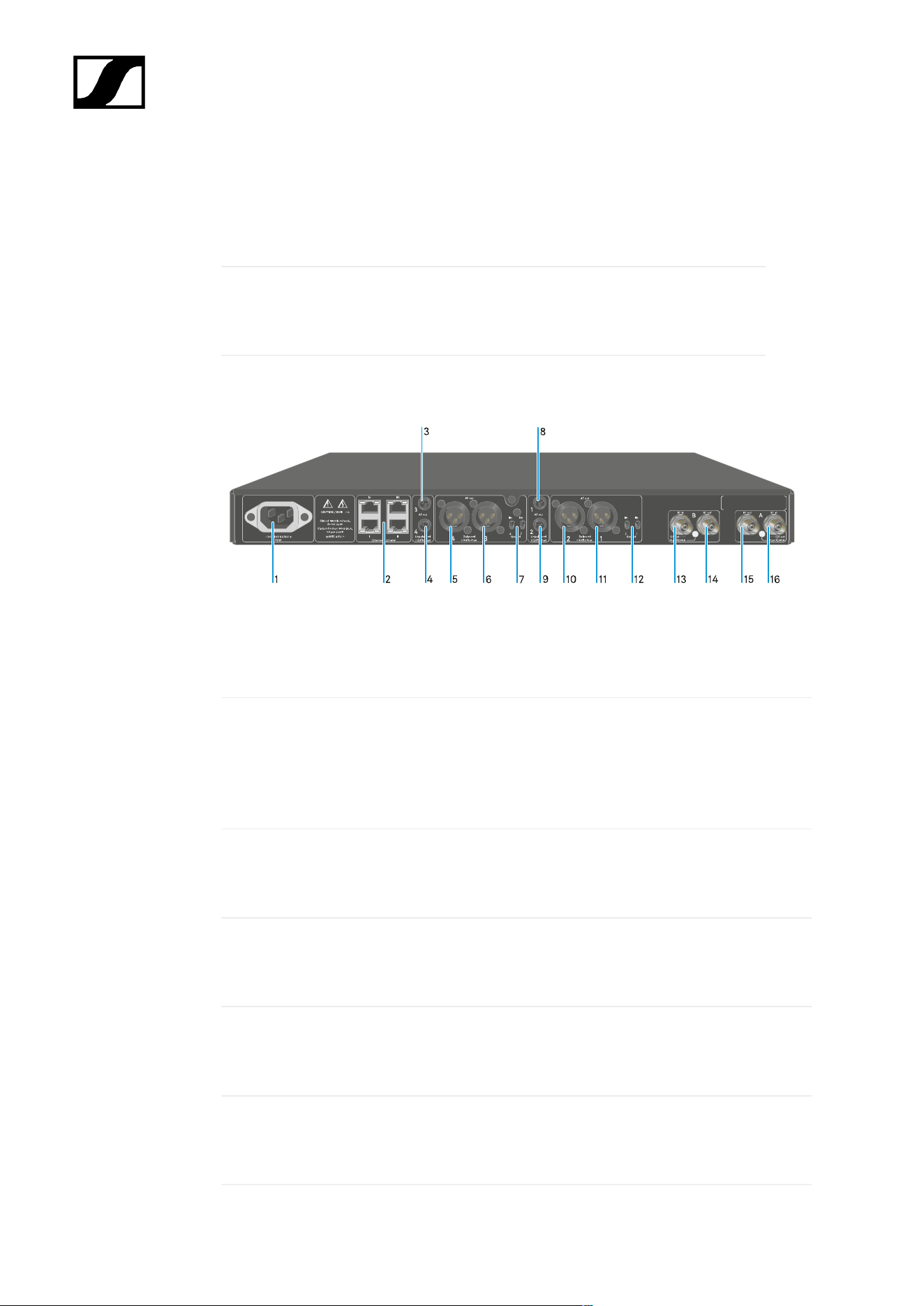
| 3 - Instruction manual
18 SYNC button for synchronizing the transmitter and receiver
• See Establishing a radio link | Synchronizing the receiver and
transmitter
19 ON/OFF button for switching the device on and off
• See Switching the receiver on and off
Back
1 Power socket
• See Connecting/disconnecting the receiver to/from the power supply system
2 RJ-45 sockets: Control of the device via network using Wireless Systems Manager /
Sennheiser Control Cockpit and Dante
• See Connecting receivers in a network
• See Connecting/disconnecting the receiver to/from the power supply system
3 6.3 mm jack socket for AF out Unbalanced audio output for channel 3
• See Outputting audio signals
4 6.3 mm jack socket for AF out Unbalanced audio output for channel 4
• See Outputting audio signals
5 XLR-3 socket for AF out Balanced audio output for channel 4
• See Outputting audio signals
6 XLR-3 socket for AF out Balanced audio output for channel 3
• See Outputting audio signals
287

| 3 - Instruction manual
7 Groundlift for channel 4 and channel 3
• See Outputting audio signals
8 6.3 mm jack socket for AF out Unbalanced audio output for channel 1
• See Outputting audio signals
9 6.3 mm jack socket for AF out Unbalanced audio output for channel 2
• See Outputting audio signals
10 XLR-3 socket for AF out Balanced audio output for channel 2
• See Outputting audio signals
11 XLR-3 socket for AF out Balanced audio output for channel 1
• See Outputting audio signals
12 Groundlift for channel 2 and channel 1
• See Outputting audio signals
13 ANT B in BNC sockets, antenna inputs
• See Connecting antennas
14 ANT B out BNC sockets, antenna outputs
• See Connecting antennas
15 ANT A out BNC sockets, antenna inputs
• See Connecting antennas
16 ANT A in BNC sockets, antenna outputs
• See Connecting antennas
288
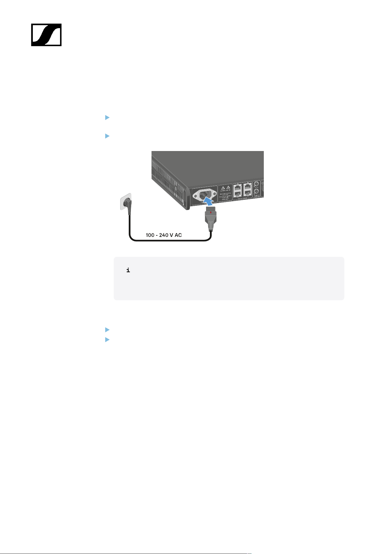
| 3 - Instruction manual
Connecting/disconnecting the receiver to/from the power supply
system
To connect the receiver to the power supply system:
Connect the mains cable IEC connector to the power socket on the rear side of the
receiver.
Connect the wall plug on the mains cable to a suitable wall outlet.
If the booster voltage for antennas is activated in the menu (see System
-> This Device menu item), it is active already before you switch on and
after you switch off the receiver.
To completely disconnect the receiver from the power supply system:
Unplug the mains cable plug from the wall socket.
Slide the red switch back and simultaneously unplug the IEC connector of the mains
cable from the power socket of the receiver.
289
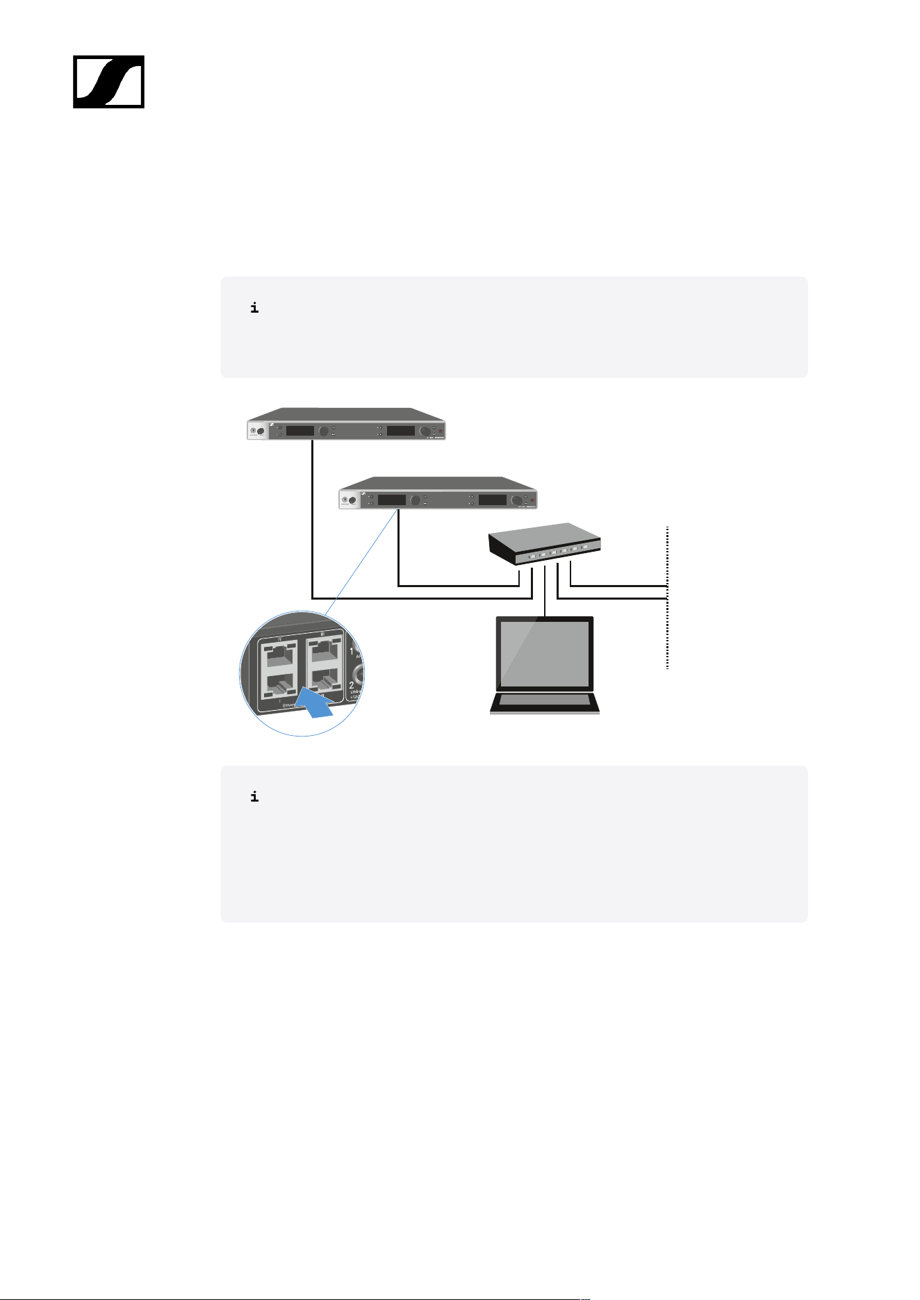
| 3 - Instruction manual
Connecting receivers in a network
You can monitor and control one or more receivers via a network connection using the
Sennheiser Wireless Systems Manager (WSM) or Sennheiser Control Cockpit (SCC)
software.
The network does not have to be a homogeneous network including only
receivers. You can integrate the receiver into your existing network infrastructure
with any other types of devices.
For more information about controlling devices via the Sennheiser Wireless
Systems Manager or Sennheiser Control Cockpit software, refer to the
instruction manual for the software. You can download the software here:
sennheiser.com/wsm
sennheiser.com/scc
290

| 3 - Instruction manual
In compact network systems that only have a limited number of receivers, the “Single Cable”
mode is the best option. This straightforward setup simplifies the installation and reduces the
cabling workload.
For larger, more extensive network configurations, the “Split or Redundancy Mode” is
recommended. In these operating modes, the differing control data can be wired separately
alongside the digital audio protocol data and also allow for redundant cabling.
When integrating several switches in a network, it is important to carefully consider the
possible effects on the network performance. A selected operating mode can, if the cabling
is faulty, restrict the network operation or lead to system failure. In this respect, it is also
important to ensure that the network switches from the respective manufacturers that
are used also support the data and audio protocols (e.g. Dante) and that they have been
configured accordingly.
The Spanning Tree Protocol (STP) has been implemented to avoid misconfigurations between
network modes and cabling and the resulting broadcast storms. The STP is configured with a
priority of 57344 and should be considered when setting up a network with managed switch
so that an EW-DX EM doesn't get the route bridge. STP could be enabled or disabled.
Detailed instructions can be obtained from the respective manufacturers of the individual
software applications.
First of all, set the network mode in the receiver, see EW-DX EM 2 Dante System ->
Network menu item and EW-DX EM 4 Dante System -> Network menu item.
Note the assignment of the sockets and the wiring examples on the following pages.
The following examples do not show all of the cabling options.
Connect the cables.
Information about the Dante Controller and the Dante network protocol settings
is available on the Audinate website: audinate.com.
Information on the use of remote software is available in the download area of
the Sennheiser website: sennheiser.com/download.
292
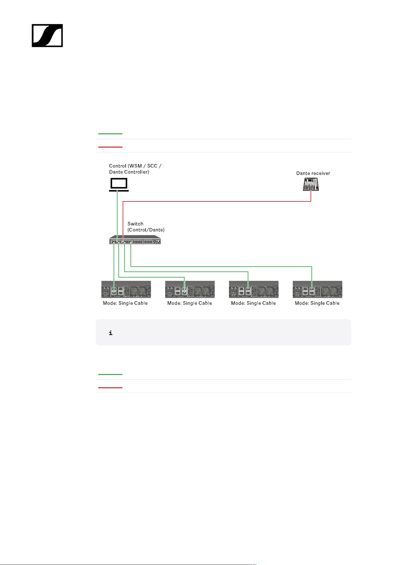
| 3 - Instruction manual
Connections and network settings
Single cable mode
Factory setting
Network control / Dante primary
Dante primary
The cable can be connected to network connections I, II or III.
Daisy-chain
Network control / Dante
Dante
293
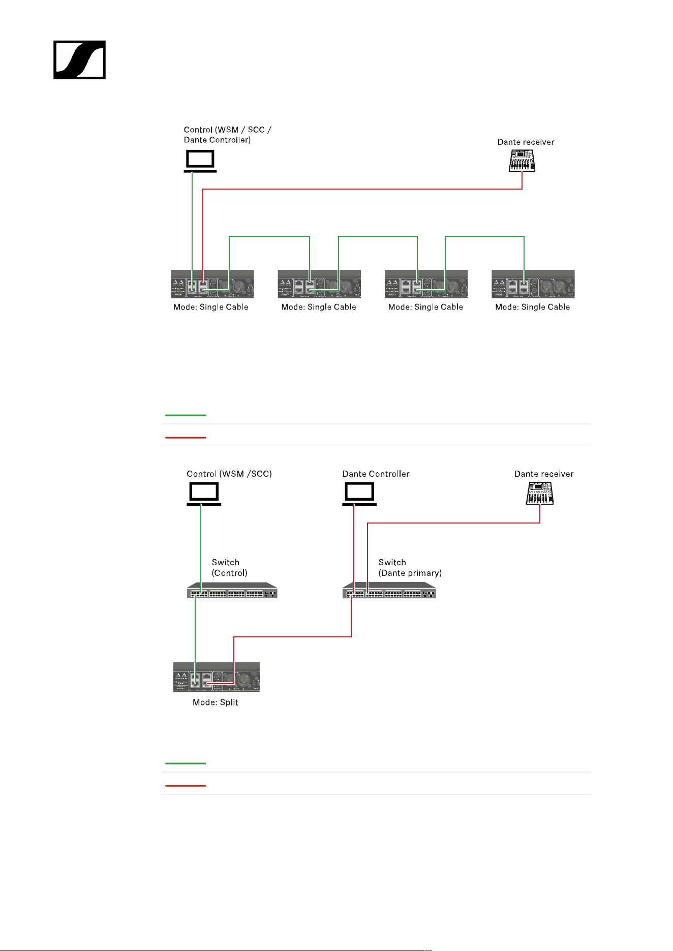
| 3 - Instruction manual
Split mode
Split 1 without daisy-chain
Network control
Dante primary
Split 1 with daisy-chain
Network control
Dante primary
294
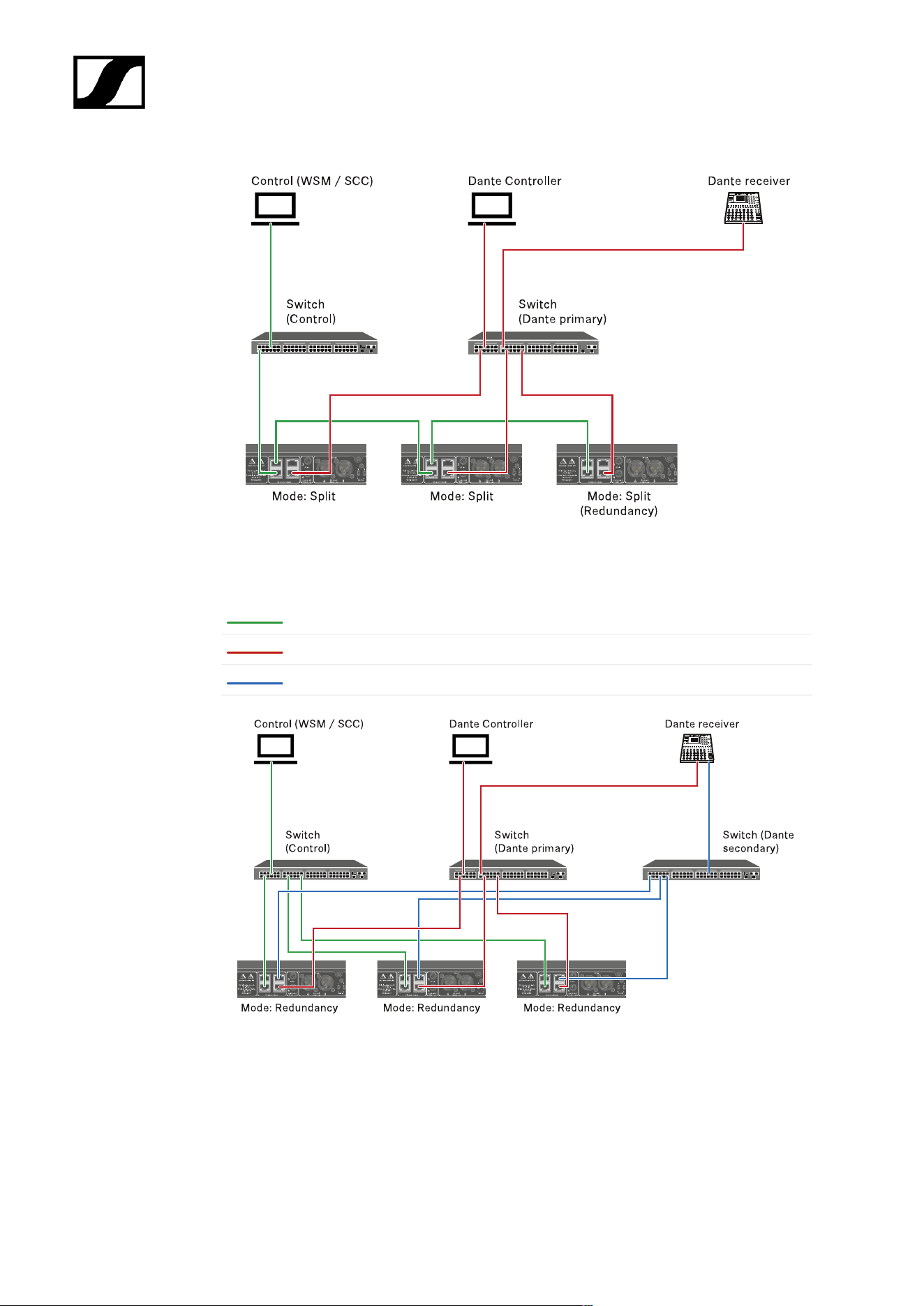
| 3 - Instruction manual
Redundancy mode
Network control
Dante primary
Dante secondary
295
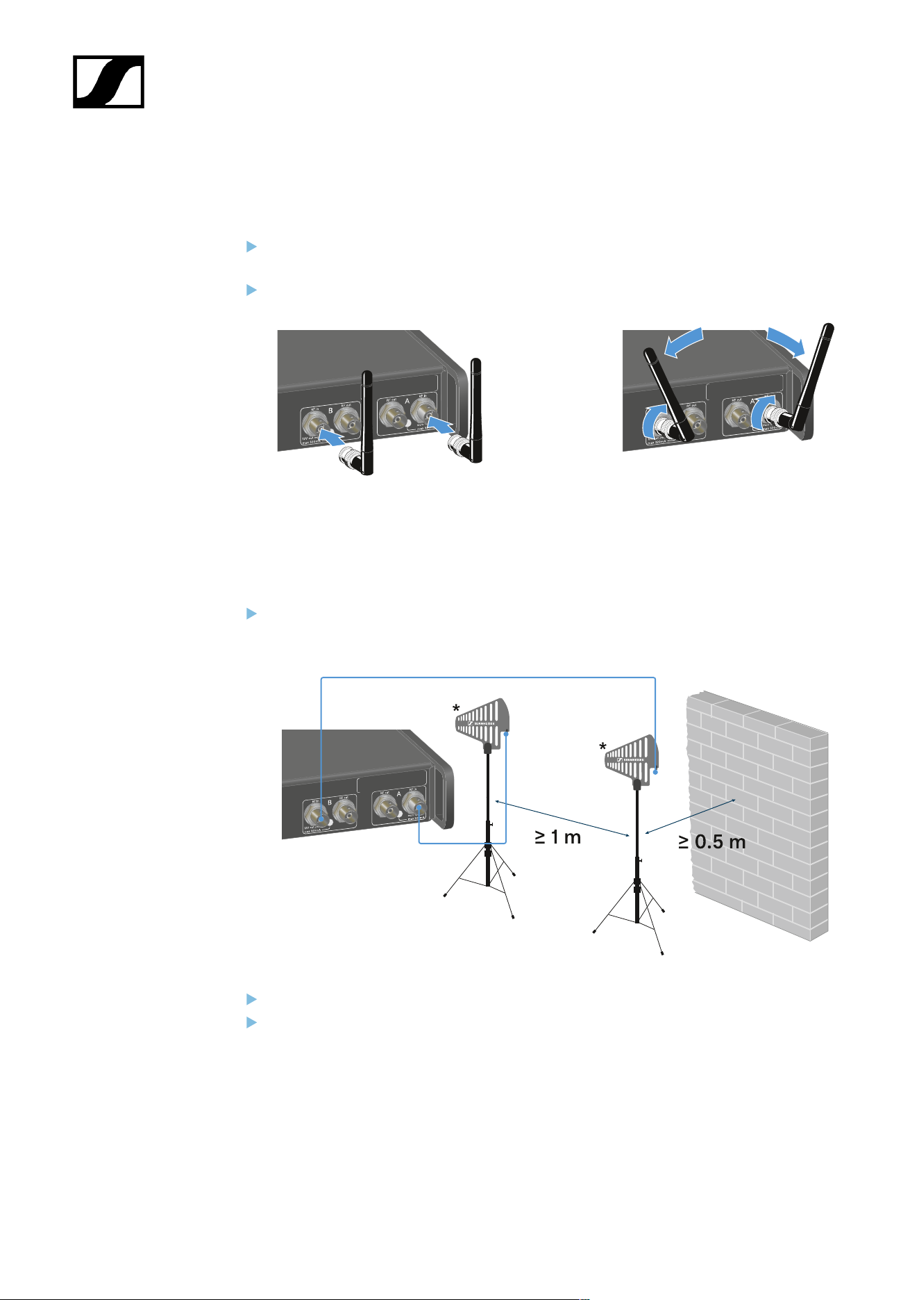
| 3 - Instruction manual
Connecting antennas
To connect the supplied rod antennas:
Connect the antennas to the two antenna inputs on the receiver as shown in the
figure.
Slightly angle the antennas to the left and right as shown in the figure.
If you are using more than one receiver, we recommend using remote antennas and
possibly the EW-D ASA antenna splitter (EW-D ASA antenna splitter).
To connect remote antennas:
Connect the antennas to the two antenna inputs on the receiver as shown in the
figure.
Observe the specified minimum spacing.
Observe the specified minimum spacing to the transmitters.
296
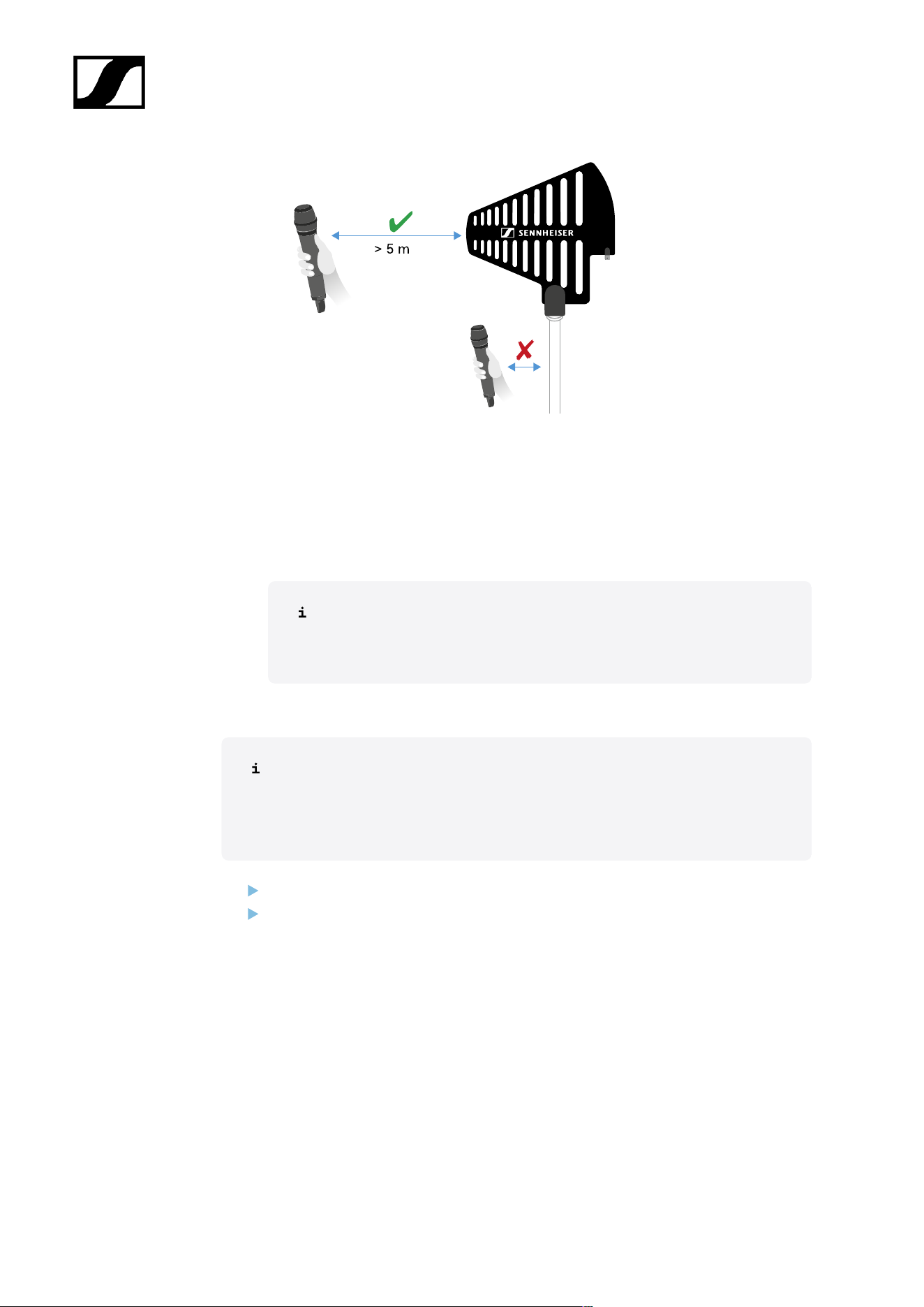
| 3 - Instruction manual
*Recommended antennas:
• ADP UHF | 470 – 1075 MHz
• AD 1800 | 1400 – 2400 MHz
• AWM UHF I | 470 – 694 MHz
• AWM UHF II | 823 – 1075 MHz
• AWM 1G8 | 1785 – 1805 MHz
If you are using more than one receiver, we recommend using remote
antennas and possibly the EW-D ASA antenna splitter (EW-D ASA
antenna splitter).
To cascade the receiver:
The EW-DX EM 4 Dante receivers have a built-in antenna splitter. This enables
you to cascade up to four receivers. This makes it possible to use 2 antennas/
antenna boosters for up to four receivers. All receivers use the same booster
frequency range.
Connect two antennas as described above.
Connect the RF out socket of the first receiver to the corresponding RF in socket of
another receiver using a short antenna cable.
297
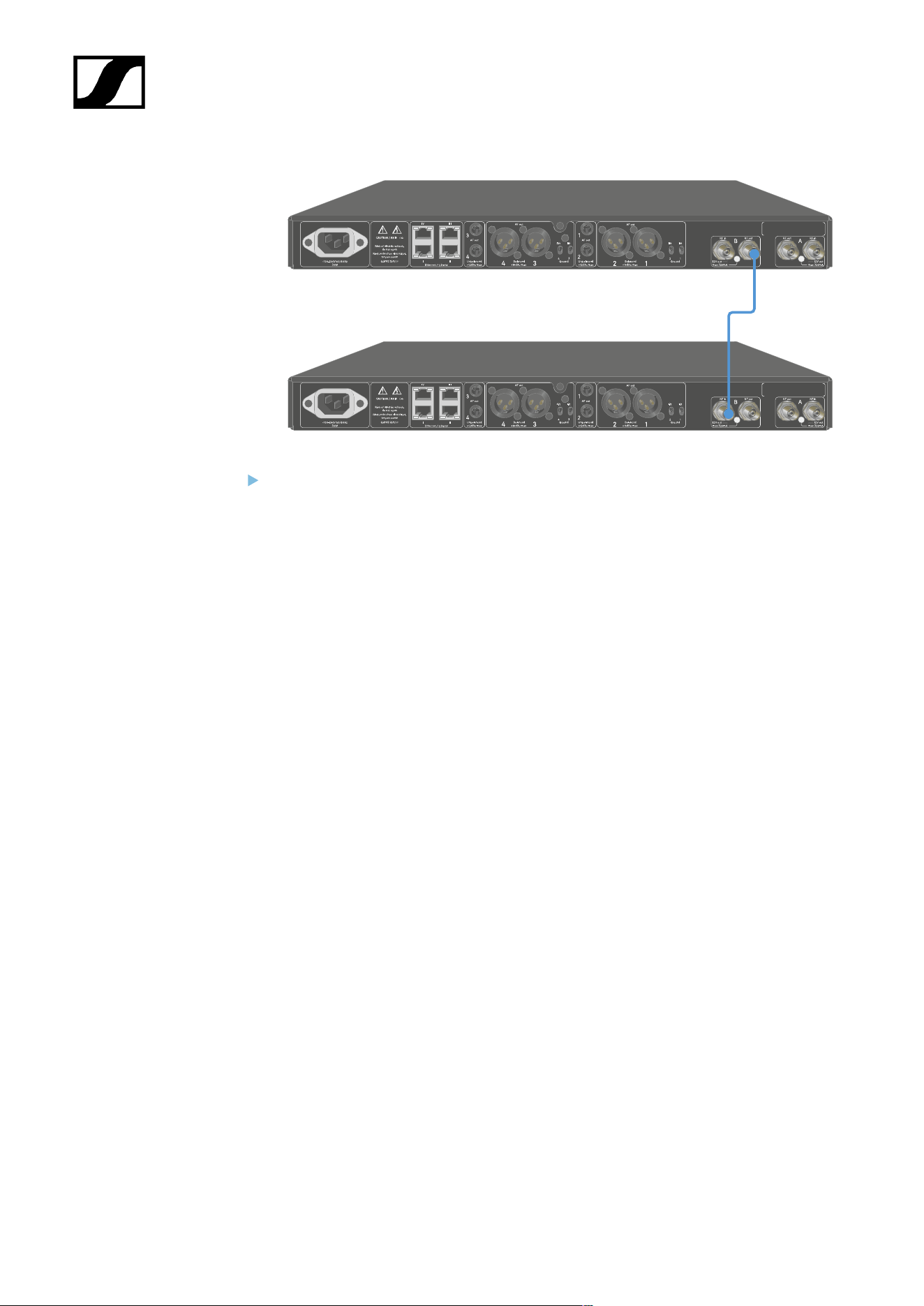
| 3 - Instruction manual
Proceed as described in the previous step for a total of four receivers.
298
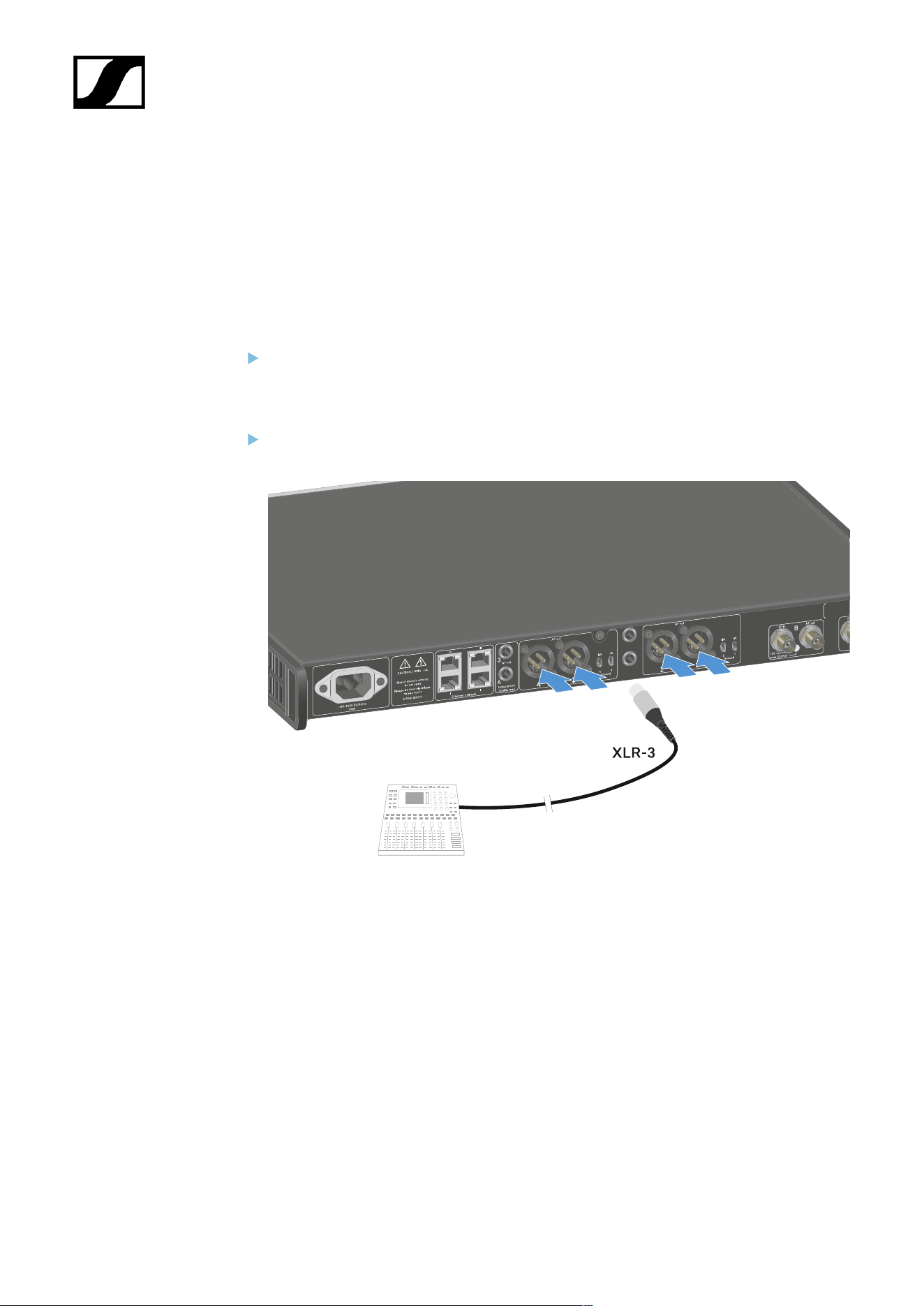
| 3 - Instruction manual
Outputting audio signals
Each of the four channels on the EW-DX EM 4 Dante has both a balanced XLR-3M output
socket and an unbalanced 6.3 mm (1/4") jack output socket.
The balanced XLR -3M output has one Groundlift switch per channel, which interrupts the
ground connection between pin 1 of the XLR connector.
Always use only one of the two output sockets for each channel.
To connect an XLR cable:
Plug the XLR cable into the AF out Balanced socket for the respective channel on the
EW-DX EM 4 Dante.
299
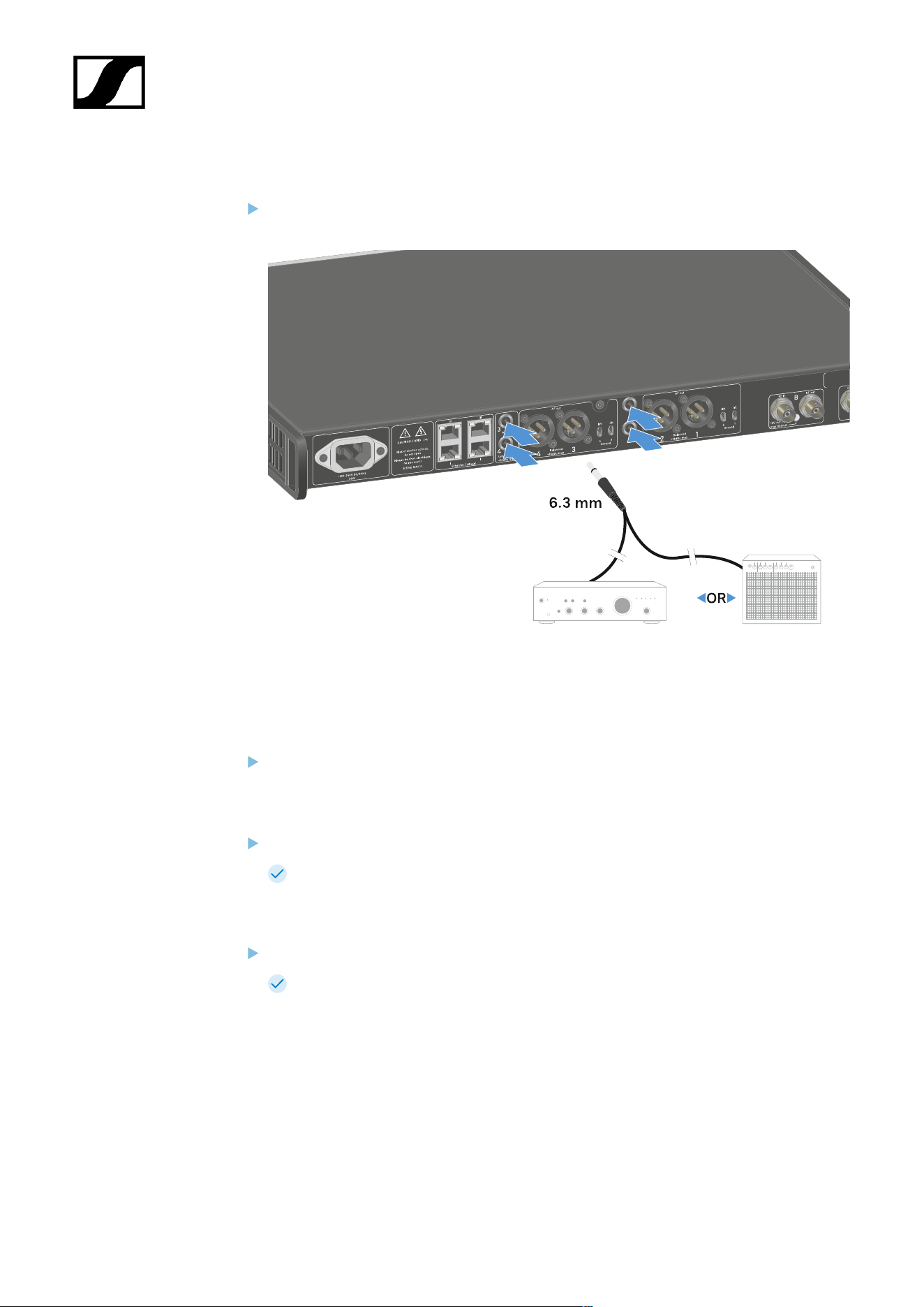
| 3 - Instruction manual
To connect a jack cable:
Plug the jack cable into the AF out Unbalanced socket for the respective channel on
the EW-DX EM 4 Dante.
To output an audio signal via Dante:
Connect the receiver as described under Connecting receivers in a network.
To adjust the Groundlift:
Slide the desired switch upwards.
Groundlift has been switched on for the corresponding AF out Balanced channel.
To switch Groundlift off:
Slide the desired switch downwards.
Groundlift has been switched off for the corresponding AF out Balanced channel.
300
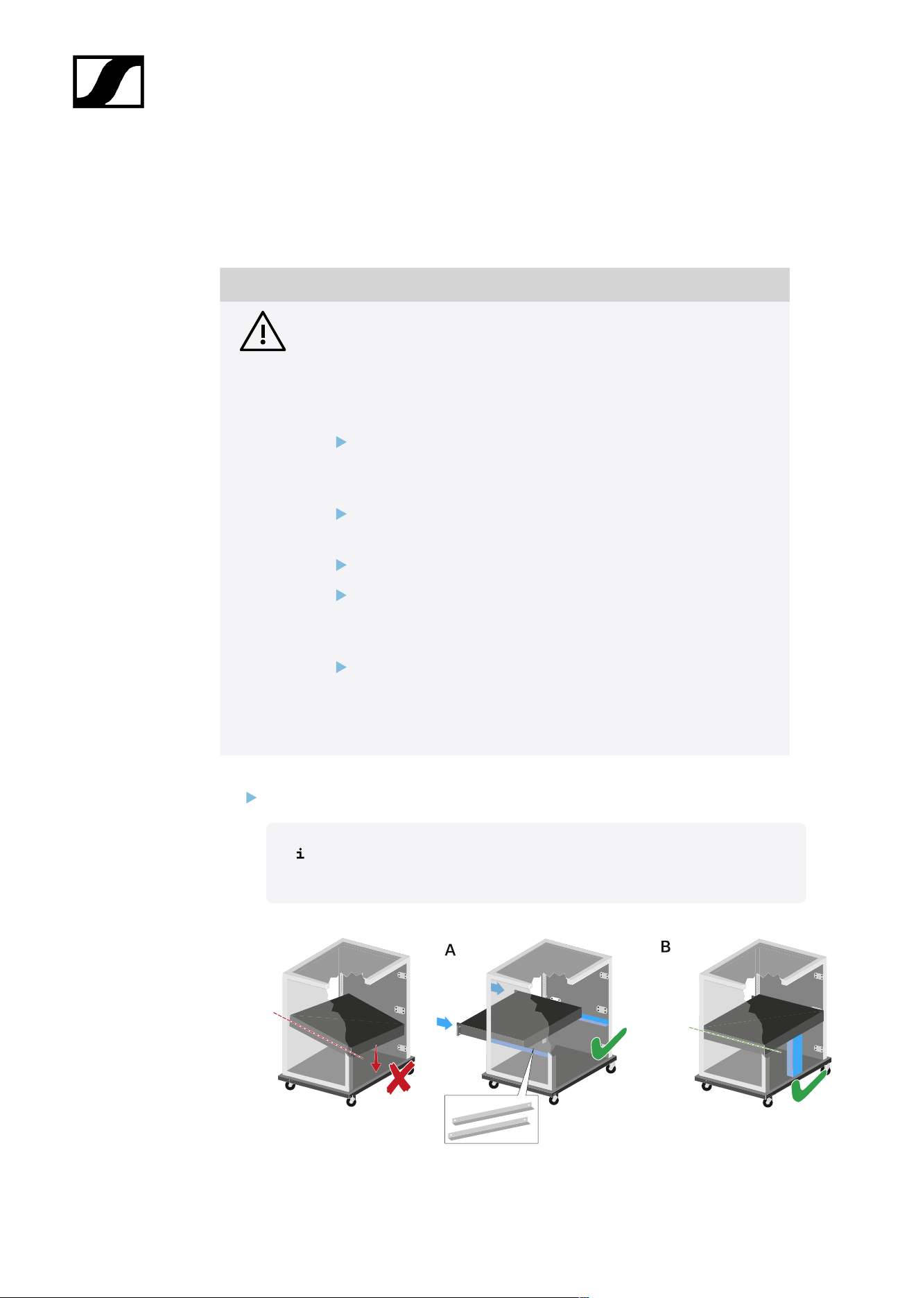
| 3 - Instruction manual
Installing receivers in a rack
You can install the receiver in any conventional 19" rack. The rack mounting angles are
already attached to the device.
NOTICE
Rack mounting poses risks!
When installing the device in a closed 19" rack or multi-rack assembly,
please consider that, during operation, the ambient temperature, the
mechanical load and the electrical potentials will be different from those
of devices which are not mounted into a rack.
Make sure that the ambient temperature within the rack does
not exceed the permissible temperature limit stated in the
specifications. See Specifications.
Ensure sufficient ventilation; if necessary, provide additional
ventilation.
Make sure that the mechanical load of the rack is even.
When connecting to the power supply system, observe the
information indicated on the type plate. Avoid overloading the
circuits. If necessary, provide overcurrent protection.
When mounting in a rack, please note that intrinsically harmless
leakage currents of the individual power supply units may
accumulate, thereby exceeding the permissible limit value. As a
remedy, ground the rack via an additional ground connection.
Support the receiver after the installation in the rack.
Due to the weight and depth of the device, there is a risk that it may break
off in the rack and become damaged as a result.
301
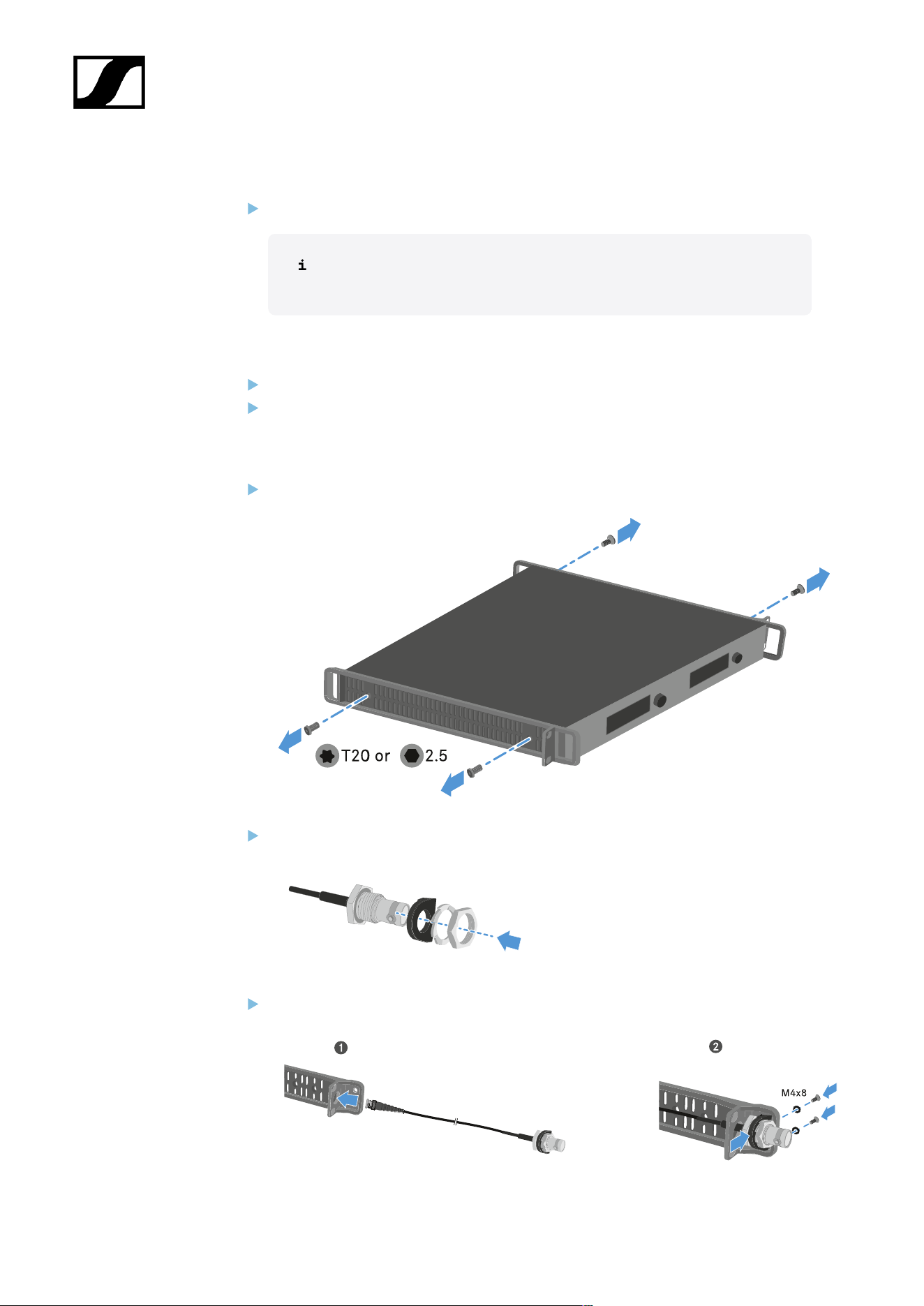
| 3 - Instruction manual
Version A
Use special rack mounting rails.
The design of the rack used must be suitable for the installation of these
mounting rails.
Version B
Use a suitable object to support the device on the rear side.
Ensure that this object cannot become loose.
Using the optional Antenna Front Mount Kit
Disconnect the mounting brackets from the sides of the receiver.
Attach the BNC connector holder to the RF patch cable as shown.
Attach the RF patch cable to the rack bracket.
302
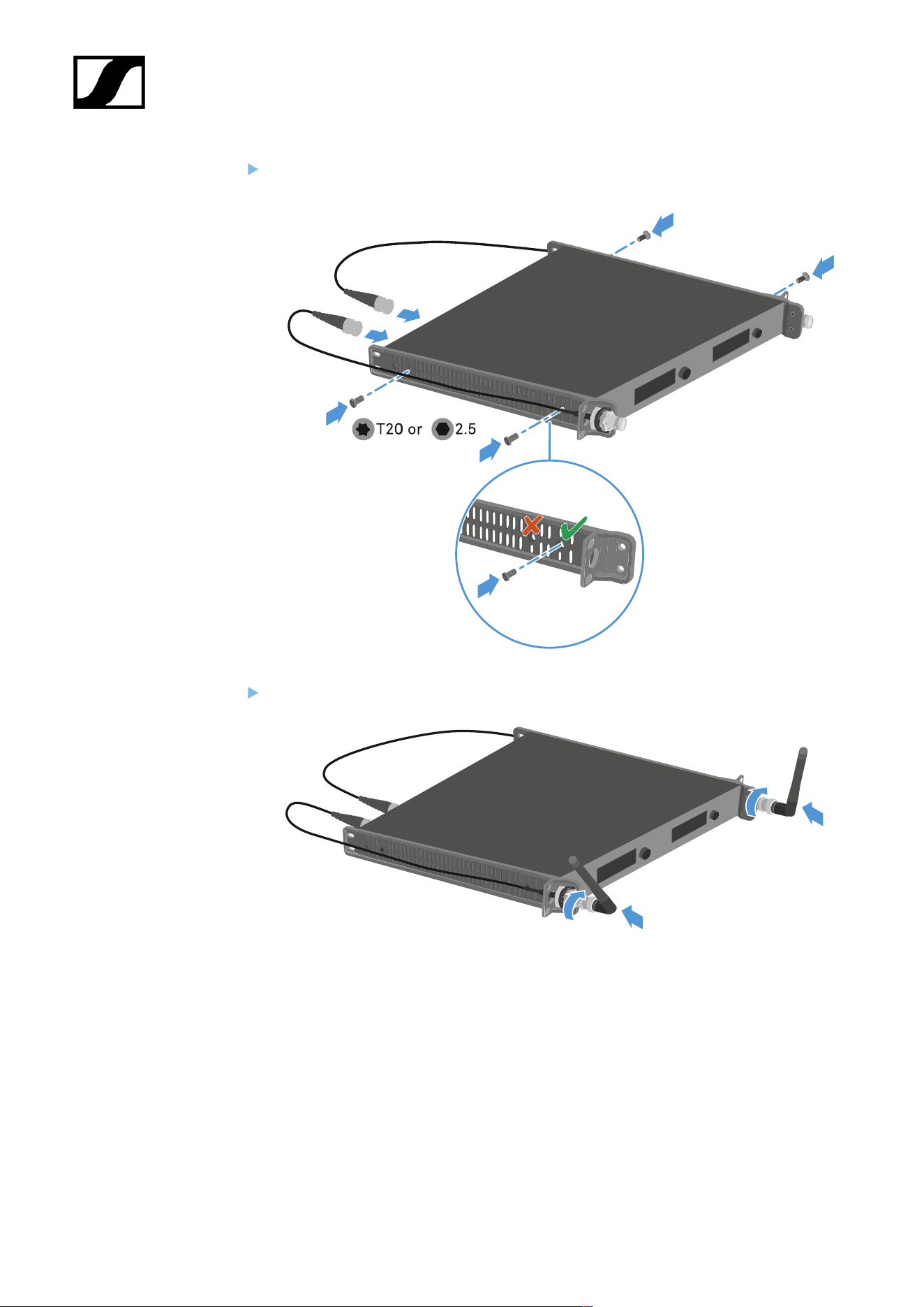
| 3 - Instruction manual
Attach the rack brackets and the RF patch cables to the receiver.
Attach the rod antennas to the RF patch cables.
303
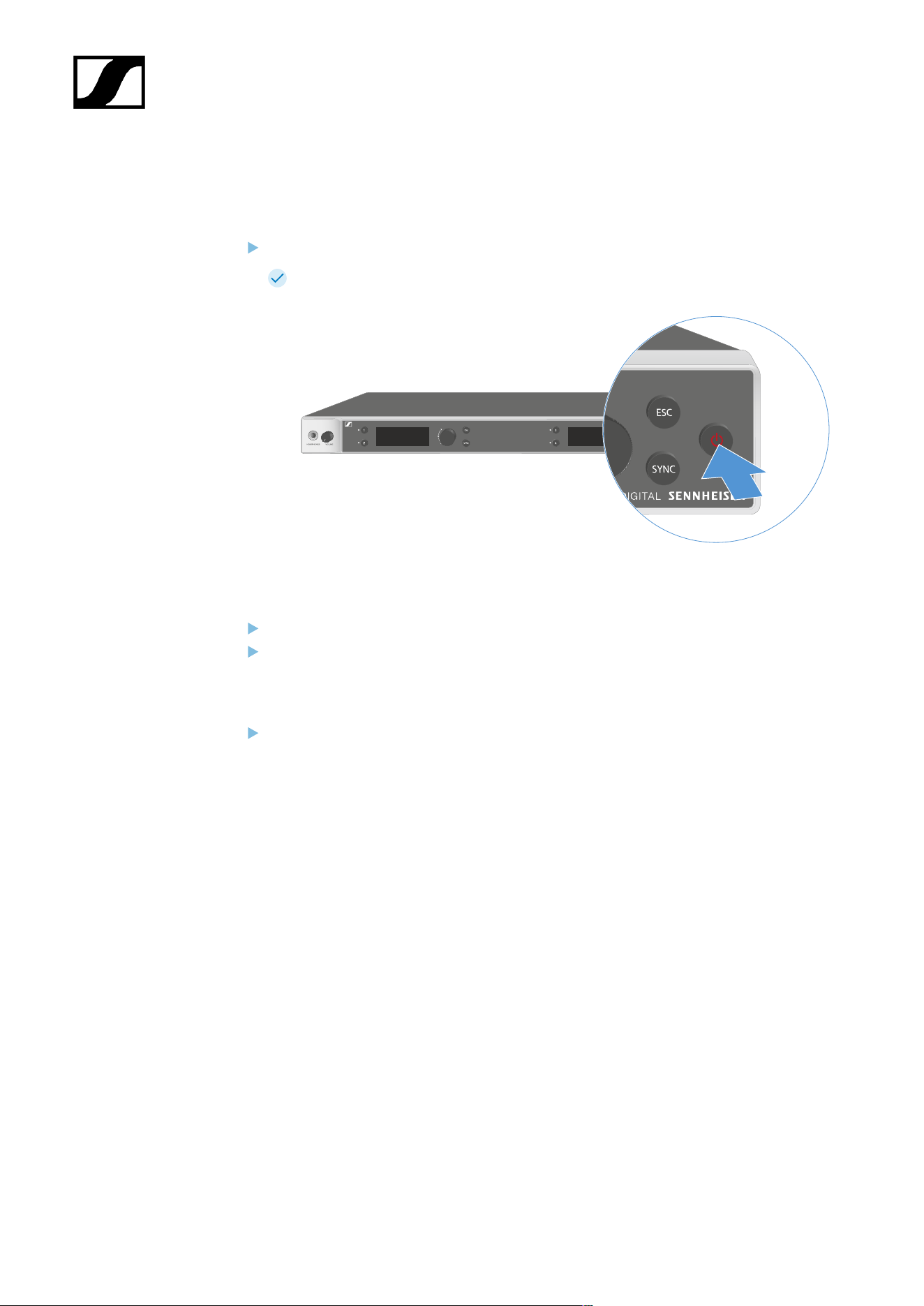
| 3 - Instruction manual
Switching the receiver on and off
To switch the receiver on:
Short-press the ON/OFF button.
The receiver switches on.
To switch the receiver to standby mode:
If necessary, deactivate the lock-off function (see Lock-off function).
Hold down the ON/OFF button until the display switches off.
To switch the receiver off completely:
Disconnect the receiver from the power supply system by unplugging the power
supply unit from the wall socket.
304
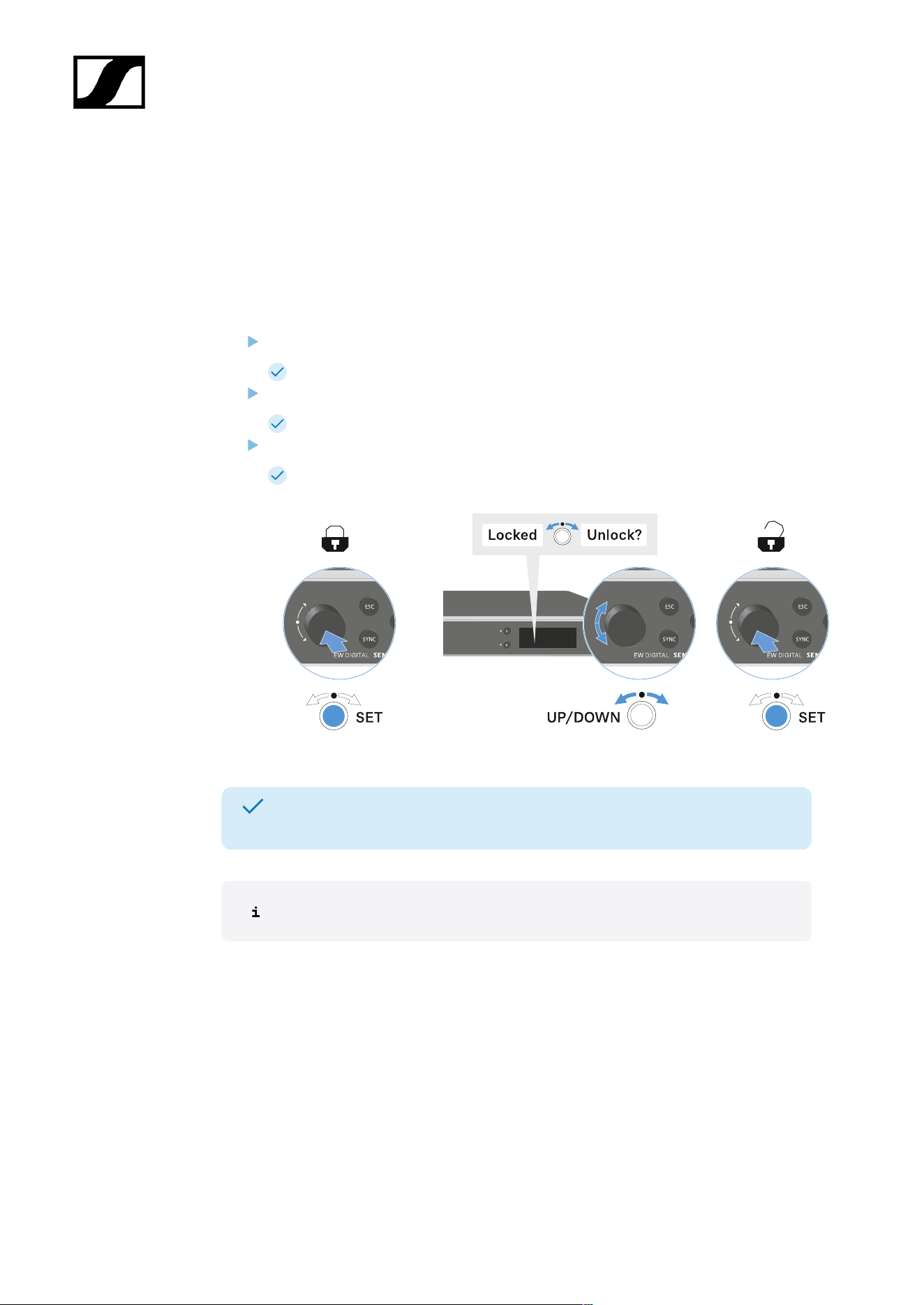
| 3 - Instruction manual
Lock-off function
You can enable or disable the automatic lock-off function in the This Device -> Device Lock
menu item (see System -> This Device menu item).
To temporarily deactivate the lock-off function:
Press the jog dial.
Locked appears in the display panel.
Turn the jog dial.
Unlock? appears in the display panel.
Press the jog dial.
Lock-off function is now temporarily deactivated.
The lock-off function remains deactivated while you are actively working in the
operating menu.
After 10 seconds of inactivity, it automatically activates again.
305
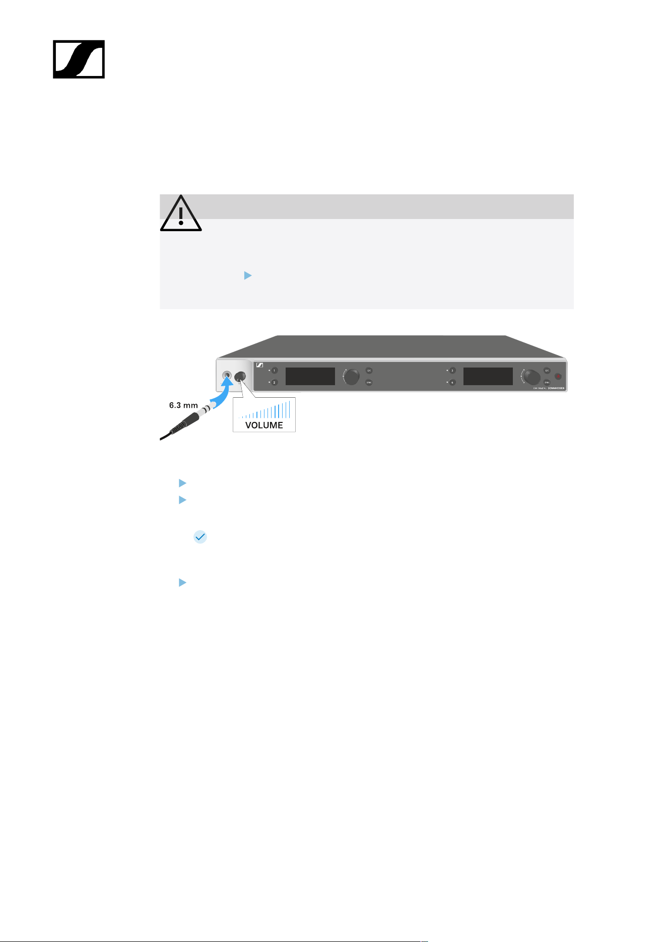
| 3 - Instruction manual
Using the headphone output
You can use the headphone output on the front of the receiver (6.3 mm jack) to listen to the
audio signals of the four channels.
CAUTION
Danger due to high volume levels
Volume levels that are too high may damage your hearing.
Turn down the volume of the headphone output before you put on
the headphone.
Connect the headphone to the headphone output.
Press the Ch 1, Ch 2, Ch 3 or Ch 4 button to listen to the audio signal from channel 1,
channel 2, channel 3 or channel 4.
The headphone icon on the display indicates which channel is currently active
on the headphone output. By default, the signal from channel 1 is active on the
headphone output.
You can control the volume by turning the volume knob next to the headphone output.
306
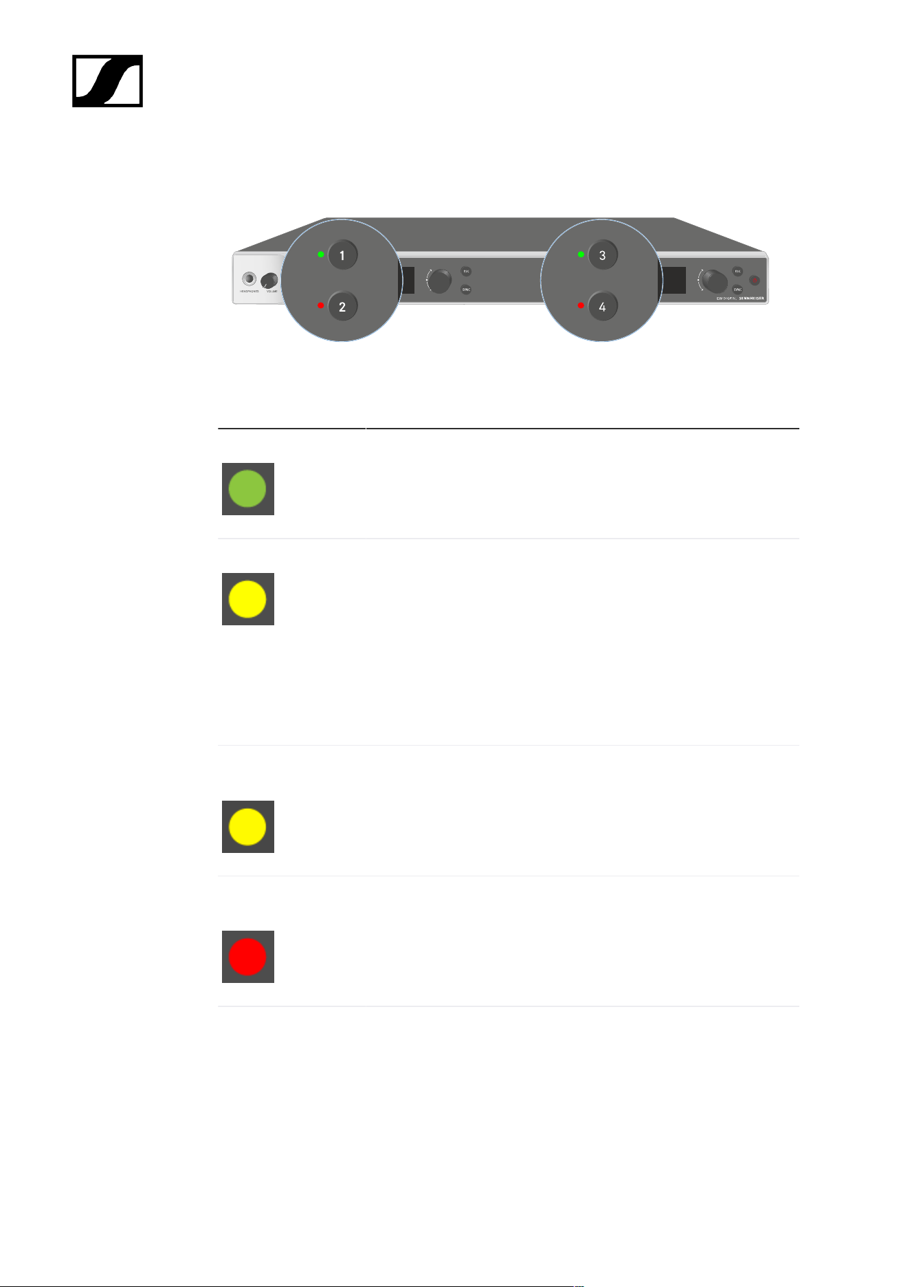
| 3 - Instruction manual
Meaning of the LEDs
The four LEDs on the front of the receiver indicate the following information for channel 1,
channel 2, channel 3 and channel 4.
The LED is green:
• The link between the transmitter and receiving channel is
established.
• The audio signal is active.
The LED is yellow:
• The link between the transmitter and receiving channel is
established.
• The audio signal is muted.
or
• No microphone module is mounted on the handheld
transmitter.
The LED is flashing
yellow:
• The link between the transmitter and receiving channel is
established.
• The audio signal is overdriven (clipping).
The LED is
continuously red:
• The link between the transmitter and receiving channel is
established.
• The audio signal is overdriven (clipping).
The LED is flashing
red:
• The link between the transmitter and receiving channel is
established.
• The battery/rechargeable battery in the paired transmitter is
low.
307

| 3 - Instruction manual
The LED is flashing
blue:
• The Bluetooth Low Energy link is being established
between the receiver and a smartphone or tablet with the
Smart Assist app.
or
• The receiving channel is being synchronized with a
transmitter.
The LED is blue:
• The firmware is being updated.
308

| 3 - Instruction manual
Displays on the receiver’s display panel
Status information such as frequency, reception quality, battery status and audio level is
shown on the display.
The display also shows the operating menu, which you can use to configure all of the settings
(see Buttons for navigating the menu).
Home screen
The home screen is the default view on the display. The following information for receiving
channel 1 and 2 or receiving channel 3 and 4 is displayed here.
Antenna switching diversity:
Indicates which of the two antennas is currently active (left or right).
Signal level:
Displays the RF signal strength for the respective channel.
Link quality:
Displays the transmission quality for the respective channel.
309

| 3 - Instruction manual
On the one hand, the transmission quality depends on the field strength (RF
level indicator on the display). However, on the other hand, it also depends on
external sources of interference that cannot be identified on the RF level indicator
(for example, they may be on the same frequency or a very close neighboring
frequency or may not affect the field strength).
As a basic principle, a value significantly higher than 50% should be achieved
for a secure transmission.
Link name:
You can assign a name to the radio link in the receiver menu (see Ch 1 - Ch 4 -> Name menu
item).
Frequency:
You can set the frequency of the radio link manually or using the Auto-Setup function.
• See Ch 1 - Ch 4 -> Frequency menu item
• See Ch 1 - Ch 4 -> Scan/Auto Setup menu item
Transmitter audio level:
Displays the audio input level for the respective channel (see Ch 1 - Ch 4 -> Gain menu item).
This level is separate from the audio level that is output from the receiver (see Ch 1 - Ch 4 ->
AF Out menu item).
Transmitter battery:
Indicates the charging status of the transmitter’s BA 70 rechargeable battery or batteries.
When using the BA 70 rechargeable battery, the remaining runtime is also displayed in hours
and minutes.
Mute mode:
The mute switch is deactivated on the received transmitter.
The mute switch on the received transmitter is set to AF Mute and the audio
signal is muted.
• EW-DX SKM-S: Configuring mute mode and muting the handheld
transmitter (EW-DX SKM-S only)
• EW-DX SK: Configuring mute mode and muting the bodypack transmitter
Headphones:
310
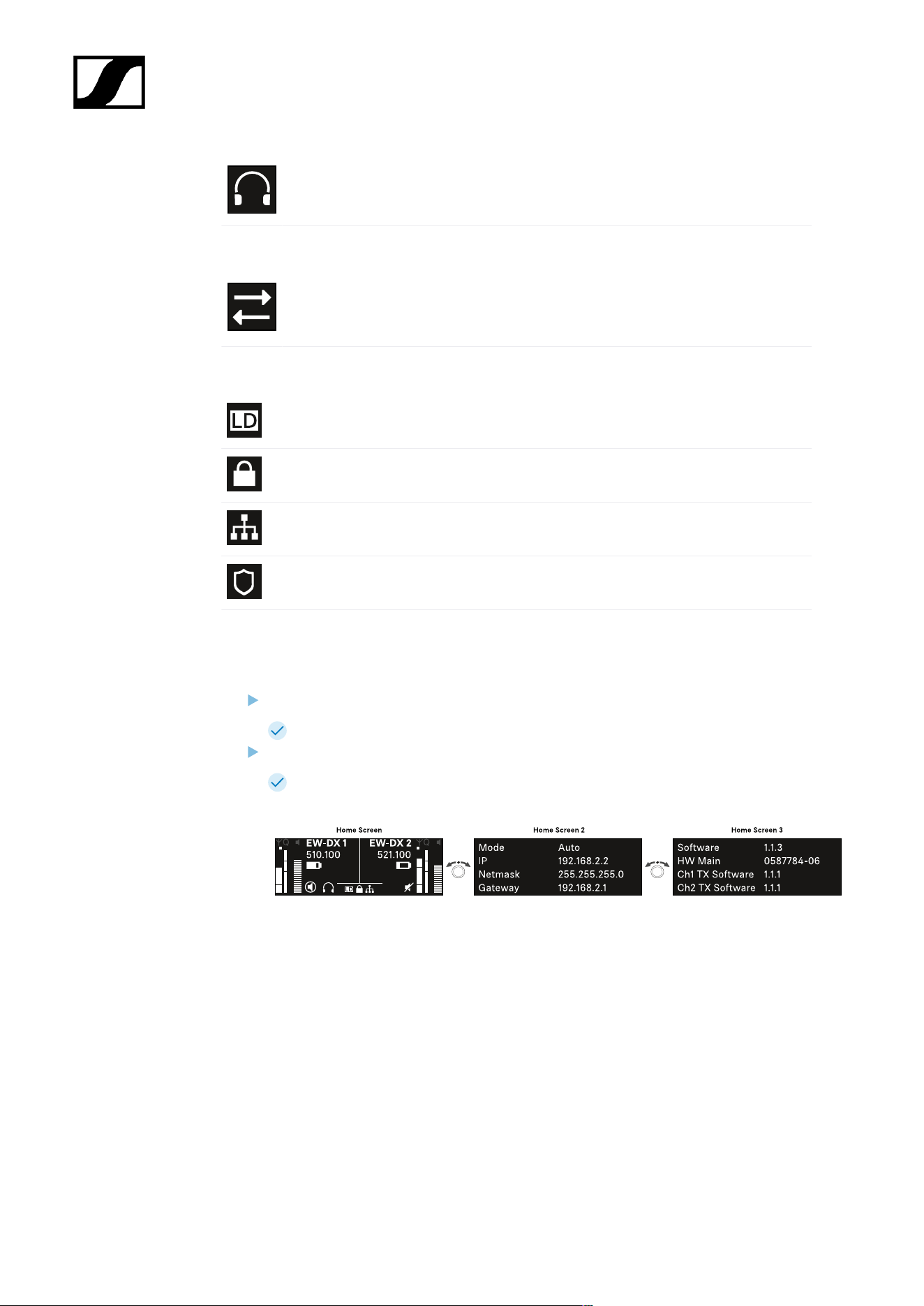
| 3 - Instruction manual
The headphones icon indicates which channel is currently active on the
headphone output (see Using the headphone output).
Sync state:
This icon indicates that different values are set for the receiving channel of the
receiver and the transmitter. These values can be synchronized (see Connecting
to the EW-DX EM receivers / synchronizing the EW-DX EM).
System icons:
The LD icon is displayed when Link Density mode is activated. See System -> Link
Density menu item.
The lock icon is displayed when the Auto Lock function is enabled. See Lock-off
function.
The network icon appears when a network connection is successfully established.
See Connecting receivers in a network.
The shield icon is displayed when AES 256 encryption is enabled. See System ->
Link Encryption menu item.
Home screens 2 and 3
Turn the jog dial on the home screen to the right.
The second home screen appears with network information for the device.
Turn the jog dial to the right again.
The third home screen appears with information about the software and
hardware.
311

| 3 - Instruction manual
Meaning of the Link Quality Indicator
The LQI (Link Quality Indicator) on the display of the receiver shows the transmission
quality for the respective channel.
On the one hand, the transmission quality depends on the field strength (RF indicator on the
receiving channel display). However, on the other hand, it also depends on external sources
of interference that cannot be identified on the RF indicator (for example, they may be on the
same frequency or a very close neighboring frequency or may not affect the RF strength).
As a basic principle, an LQI value significantly higher than 50% should be achieved for a
secure transmission.
The LQI display shows the following information:
Green range from 50% to 100%:
• No transmission errors
The transmission quality is good enough to ensure an audio quality of 100%.
Yellow range from 20% to 49%:
• Individual transmission errors: short-term error correction active
• Individual audio artifacts may be audible
There are initial transmission errors. In rare cases, there are initial audible audio artifacts.
Error correction may be active in this case.
312

| 3 - Instruction manual
Orange range from 1% to 19%:
• Frequent transmission errors: long-term error correction active
• Risk of audio drop-outs
The transmission errors increase, which means that the error correction duration also
increases. There is a risk of audio drop-outs.
Red range 0%:
• No transmission
In this range, the transmission quality is so poor that audio drop-outs can no longer be
avoided.
313

| 3 - Instruction manual
Status messages
In certain situations, status messages may appear on the display.
AF Peak
The device is experiencing
repeated or prolonged audio
overload.
• Check the input signal on
the transmitter and adjust
it.
RF Peak
The antenna signal is
overmodulated.
• Increase the distance
between the receiving
antenna and the
transmitter.
Low Signal
The received signal is too low
or the transmission quality is
insufficient.
• Check that the antenna is
properly connected and
inspect the system wiring.
• Check that the transmitter
is within the reception
range.
• Check the orientation of the
receiver’s antenna.
Low Battery
The transmitter’s batteries or
rechargeable battery pack have
little battery life remaining (less
than 30 minutes).
• Replace the rechargeable
battery or batteries.
314

| 3 - Instruction manual
NoLink
No link to a transmitter.
• Verify that the transmitter is
on and within range.
• Check whether the
transmitter is muted (“RF
Mute” setting).
315
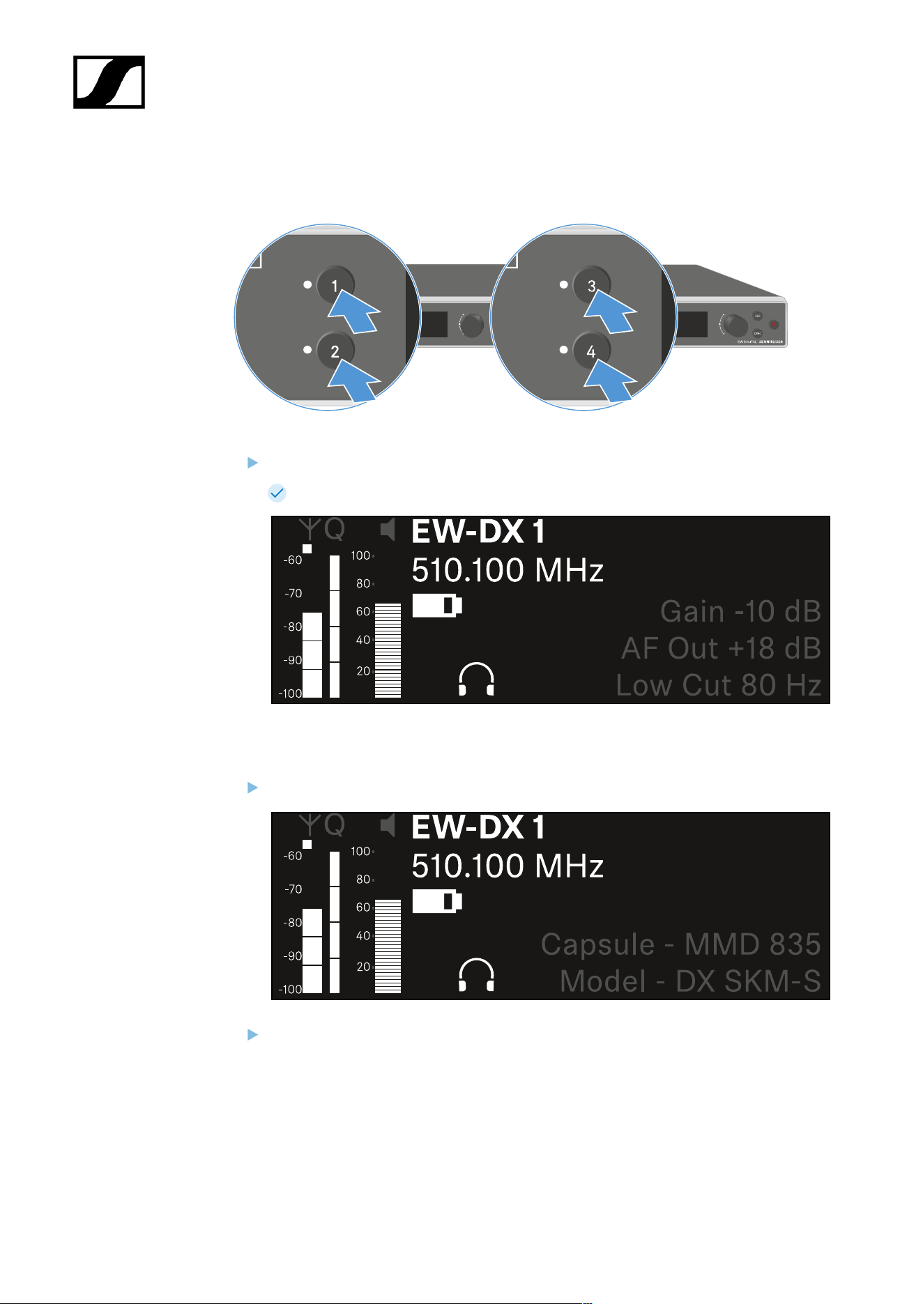
| 3 - Instruction manual
Channels 1 to 4
On the receiver’s home screen, press the Ch 1, Ch 2, Ch 3 or Ch 4 button.
The home screen for channel 1, channel 2, channel 3 or channel 4 appears.
In addition to the status information displayed on the home screen, information about
the channel’s audio settings is also displayed.
Turn the jog dial to the right to view more information about the received transmitter.
Turn the jog dial further to the right to mute or unmute the channel’s audio signal.
316
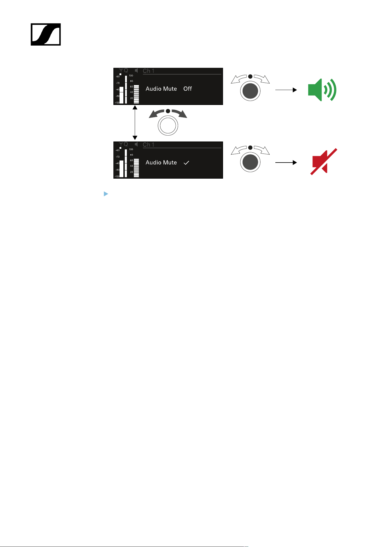
| 3 - Instruction manual
Press the jog dial to confirm your selection.
317
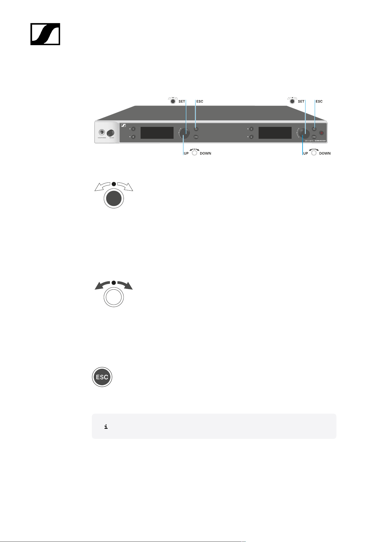
| 3 - Instruction manual
Buttons for navigating the menu
Use the following buttons to navigate through the receiver’s operating menu.
Press the jog dial
• Jumps from the home screen to the operating menu
• Calls up a menu item
• Changes to a submenu
• Saves settings
Turn the jog dial
• Selects a standard display (see Displays on the receiver’s display panel)
• Changes to the previous or next menu item
• Changes the setting of a menu item
Press the ESC button
• Cancels the entry and returns to the previous display
Opening the menu and navigating the menu items
318

| 3 - Instruction manual
Opening the menu and navigating the menu items
To open the menu:
Press the jog dial when you are on the home screen.
Turn the jog dial to navigate to your desired menu item.
Press the jog dial to open the selected menu item.
To exit the menu:
Press the ESC button to exit the menu and return to the home screen.
Changes that were not previously saved by pressing the jog dial will be lost.
319
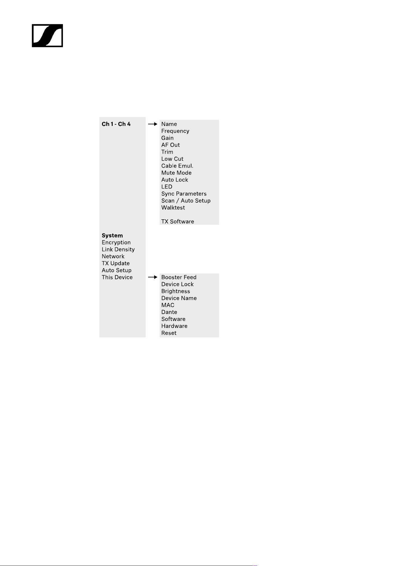
| 3 - Instruction manual
Menu structure
The figure shows the complete menu structure in an overview.
Version: firmware 3.0.0
320

| 3 - Instruction manual
Setting options in the menu
In the receiver menu, you can configure the following settings.
Changing the name of the radio link
• Ch 1 - Ch 4 -> Name menu item
Adjusting frequencies
• Ch 1 - Ch 4 -> Frequency menu item
Adjusting the gain of the wireless link
• Ch 1 - Ch 4 -> Gain menu item
Setting the output level of the audio signal
• Ch 1 - Ch 4 -> AF Out menu item
Adjusting the trim of the connected transmitter
• Ch 1 - Ch 4 -> Trim menu item
Adjusting the low-cut filter
• Ch 1 - Ch 4 -> Low Cut menu item
Configuring cable emulation for the bodypack transmitter
• Ch 1 - Ch 4 -> Cable Emul. menu item
Setting the function of the transmitter’s mute switch
• Ch 1 - Ch 4 -> Mute Mode menu item
Enabling the transmitter’s automatic lock-off function
• Ch 1 - Ch 4 -> Auto Lock menu item
Configuring the behavior of the transmitter’s LEDs
• Ch 1 - Ch 4 -> LED menu item
Activating/deactivating the parameters to be synchronized on the transmitters
• Ch 1 - Ch 4 -> Sync Parameters menu item
Performing a frequency scan and automatic frequency setup
• Ch 1 - Ch 4 -> Scan/Auto Setup menu item
321

| 3 - Instruction manual
Check the reception quality within the operating environment
• Ch 1- Ch 4 -> Walktest menu item
Viewing the software version of the connected transmitters
• Ch 1 - Ch 4 -> TX Software menu item
Configuring different system settings
• Enabling AES 256 encryption
• Setting transmission mode
• Configuring network settings
• Updating the firmware for the transmitters
• Activating the Auto Setup function
• Changing device names
• System menu item
You can find an overview of the entire menu structure under Menu structure.
Ch 1 - Ch 4 -> Name menu item
In the Name menu item, you can define the name of the link for the channel in question.
This name is the name of the radio link between the transmitter and receiving
channel. You can set the name of the receiver as it will appear in a network from
the This Device menu in the system menu. See System -> This Device menu
item.
To open the Name menu item:
In the menu, navigate to the Name menu item for the desired channel.
Press the jog dial to open the menu.
322

| 3 - Instruction manual
The following view is displayed:
To enter the desired link name:
Turn the jog dial to select the desired character.
Press the jog dial to go to the next position.
At the last position, press the jog dial to save the selected name.
Or
Press the ESC button to cancel the entry without saving the settings.
For the chosen link name to appear on the display of the received transmitter,
you must synchronize the channel (Connecting to the EW-DX EM receivers /
synchronizing the EW-DX EM).
323
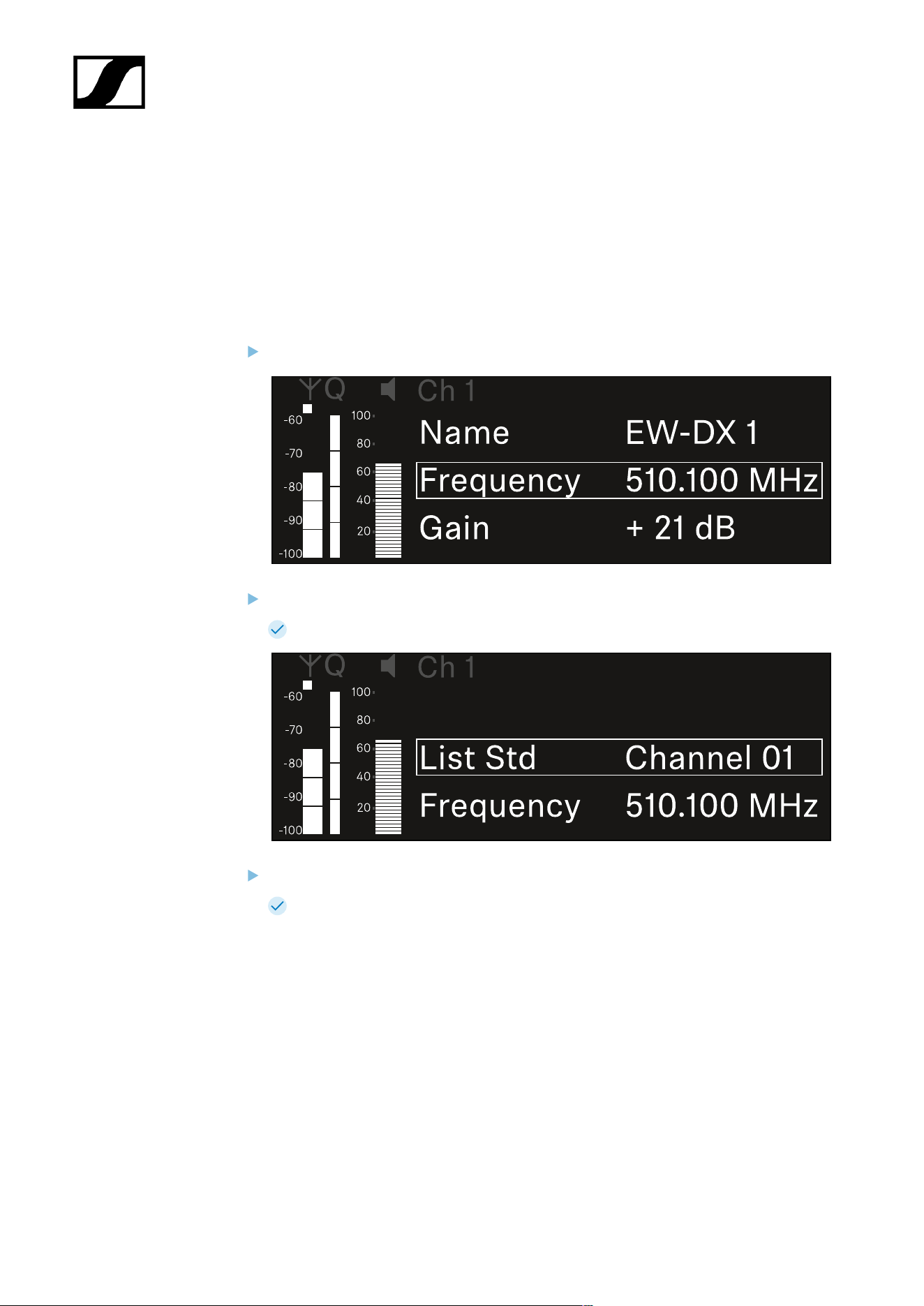
| 3 - Instruction manual
Ch 1 - Ch 4 -> Frequency menu item
In the Frequency menu item, you can adjust the frequency for the channel in question.
You can select a frequency from the predefined list or set the frequency manually.
To open the Frequency menu item:
In the menu, navigate to the Frequency menu item for the desired channel.
Press the jog dial to open the menu.
The following view is displayed:
Rotate the jog dial to select between the List and Frequency subitems.
The List subitem allows you to select a frequency from the predefined list. The
Frequency subitem lets you set the desired frequency manually.
324

| 3 - Instruction manual
To select a frequency from a predefined list:
Open the List subitem.
Rotate the jog dial to choose between the predefined list (List Std) and the user-
defined list (List Usr).
You can create a custom list using the Wireless Systems Manager
(WSM) software and upload it to the receiver. For more information on
the WSM software, see:
sennheiser.com/wsm
Press the jog dial to confirm your selection.
Rotate the jog dial to select the desired channel from the list.
The frequency assigned to the channel is displayed.
Press the jog dial to save the selected channel.
Or
Press the ESC button to cancel the entry without saving the settings.
325

| 3 - Instruction manual
To set the frequency manually:
Open the Frequency subitem.
Turn the jog dial to set the MHz range for the frequency.
Press the jog dial to confirm your selection.
Turn the jog dial to set the kHz range for the frequency.
Press the jog dial to save your selected frequency.or
Or
Press the ESC button to cancel the entry without saving the settings.
326

| 3 - Instruction manual
Ch 1 - Ch 4 -> Gain menu item
Under the Gain menu item, you can set the audio level of the audio signal coming from the
received transmitter (e.g. vocals or speech via EW-DX SKM or guitar via EW-DX SK).
• Setting range: -3 dB to +42 dB in increments of 3 dB
To open the Gain menu item:
In the menu, navigate to the Gain menu item for the desired channel.
Press the jog dial to open the menu.
The following view is displayed:
Turn the jog dial to set the desired value.
Press the jog dial to save your setting.
Or
Press the ESC button to cancel the entry without saving the settings.
327
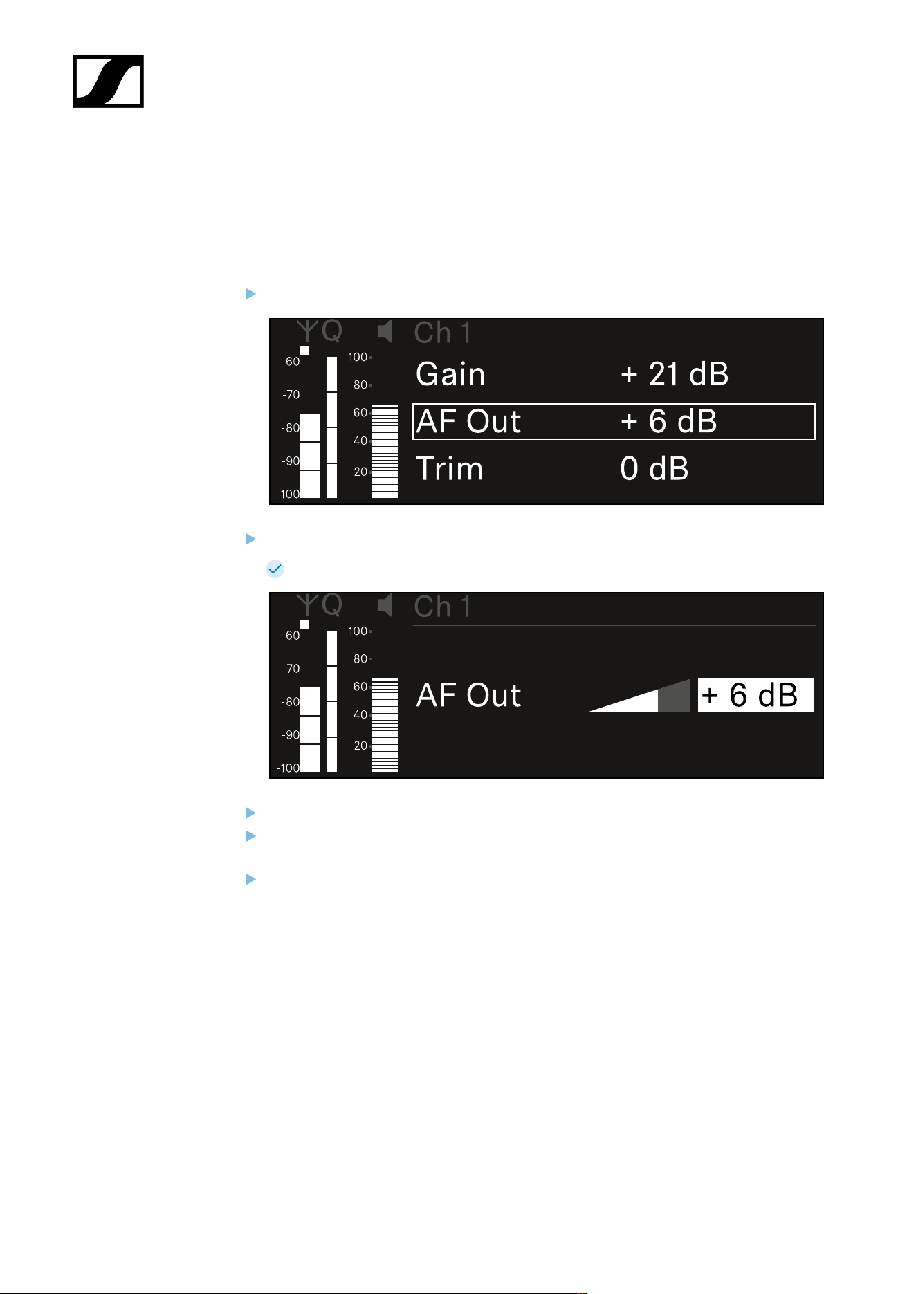
| 3 - Instruction manual
Ch 1 - Ch 4 -> AF Out menu item
In the AF Out menu item, you can set the audio level that is output via the audio outputs of
the particular receiving channel.
To open the AF Out menu item:
In the menu, navigate to the AF Out menu item for the desired channel.
Press the jog dial to open the menu.
The following view is displayed:
Turn the jog dial to set the desired value.
Press the jog dial to save your setting.
Or
Press the ESC button to cancel the entry without saving the settings.
328

| 3 - Instruction manual
Ch 1 - Ch 4 -> Trim menu item
In the Trim menu item, you can adjust the audio level of the received transmitter to input
signals of different volumes.
For example, if you are using multiple transmitters in alternation for a single
receiving channel, you can adjust the transmitters to the different input signals
using the trim setting. You do not need to change the channel’s gain setting.
• Setting range: -12 dB to +6 dB in increments of 1 dB
To open the Trim menu item:
In the menu, navigate to the Trim menu item for the desired channel.
Press the jog dial to open the menu.
The following view is displayed:
Turn the jog dial to set the desired value.
Press the jog dial to save your setting.
Or
Press the ESC button to cancel the entry without saving the settings.
329


| 3 - Instruction manual
Ch 1 - Ch 4 -> Low Cut menu item
In the Low Cut menu item, you can set the value of the low cut filter for the respective
channel.
Setting range:
• For EW-DX SK | EW-DX SK 3-PIN: Off, 30 Hz, 60 Hz, 80 Hz, 100 Hz, 120 Hz
• For EW-DX SKM | EW-DX SKM-S: 60 Hz, 80 Hz, 100 Hz, 120 Hz
To open the Low Cut menu item:
In the menu, navigate to the Low Cut menu item for the desired channel.
Press the jog dial to open the menu.
The following view is displayed:
Turn the jog dial to set the desired value.
Press the jog dial to save your setting.
Or
Press the ESC button to cancel the entry without saving the settings.
For the set value to be applied to the received transmitter, you must synchronize
the channel (Connecting to the EW-DX EM receivers / synchronizing the EW-
DX EM).
331

| 3 - Instruction manual
Ch 1 - Ch 4 -> Cable Emul. menu item
In the Cable Emul. menu item, you can emulate instrument cable lengths:
Setting range:
• Off, Type 1, Type 2, Type 3
To open the Cable Emul. menu item:
In the menu, navigate to the Cable Emul. menu item for the desired channel.
Press the jog dial to open the menu.
The following view is displayed:
Turn the jog dial to set the desired value.
Press the jog dial to save your setting.
Or
Press the ESC button to cancel the entry without saving the settings.
332
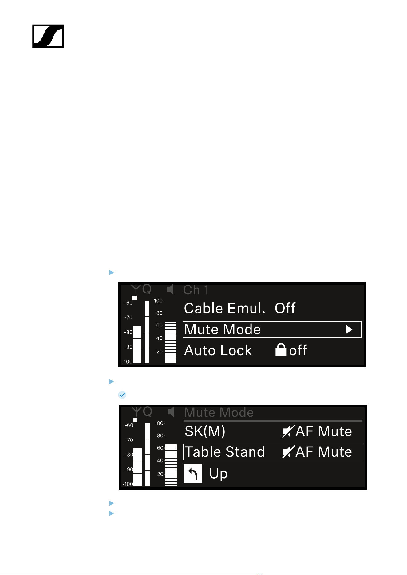
| 3 - Instruction manual
Ch 1 - Ch 4 -> Mute Mode menu item
In the Mute Mode menu item, you can set the function of the mute switch on the connected
transmitter (EW-DX SK, EW-DX SK 3-PIN, EW-DX SKM-S, EW-DX TS).
EW-DX SKM-S, EW-DX SK/EW-DX SK 3-PIN setting range:
• Disabled: The mute switch has no function.
• RF Mute: The RF signal is deactivated when the mute switch is on.
• AF Mute: The audio signal is muted when the mute switch is on.
EW-DX TS setting range:
• Disabled: The MUTE button has no function.
• AF Mute: The audio signal is muted when the MUTE button is pressed. Pressing the
button again activates the audio signal.
• PTT (Push to talk): Press and hold the MUTE button to activate the audio signal.
• PTM (Push to mute): Press and hold the MUTE button to mute the audio signal.
To open the Mute Mode menu item:
In the menu, navigate to the Mute Mode menu item for the desired channel.
Press the jog dial to open the menu.
The following view is displayed:
Turn the jog dial to set the desired value.
Press the jog dial to save your setting.
333


| 3 - Instruction manual
Ch 1 - Ch 4 -> Auto Lock menu item
In the Auto Lock menu item, you can activate or deactivate the lock-off for the received
transmitter.
The lock-off prevents the transmitter from being unintentionally switched off and also
prevents any changes to the transmitter’s menu.
If you want to change settings in the transmitter’s menu while the lock-off is
active, you have to temporarily disable the lock-off:
• EW-DX SKM: Lock-off function
• EW-DX SK: Lock-off function
To open the Auto Lock menu item:
In the menu, navigate to the Auto Lock menu item for the desired channel.
Press the jog dial to open the menu.
The following view is displayed:
Turn the jog dial to set the desired value.
Press the jog dial to save your setting.
Or
Press the ESC button to cancel the entry without saving the settings.
335

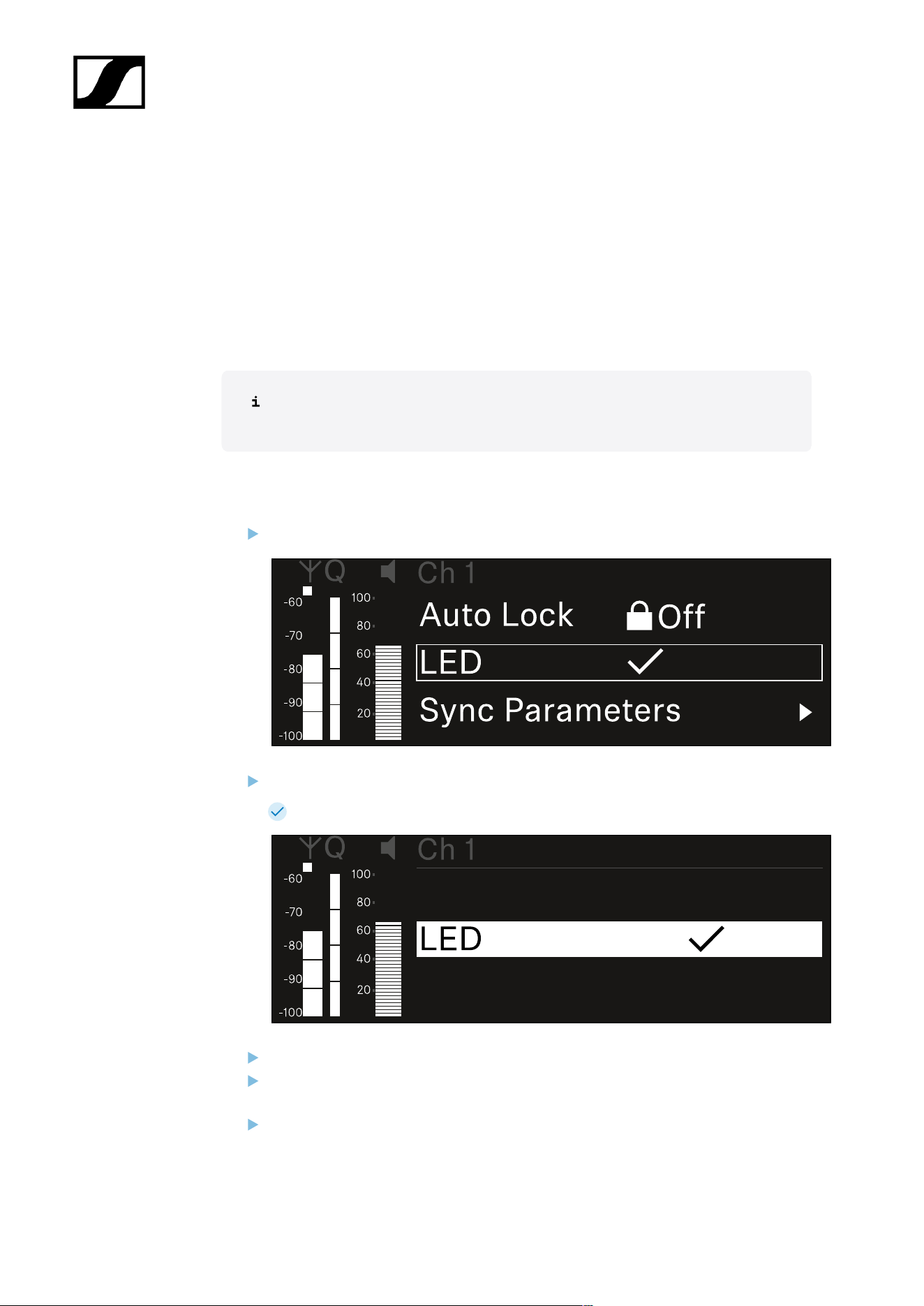
| 3 - Instruction manual
Ch 1 - Ch 4 -> LED menu item
The LED menu item allows you to set the behavior of the LINK LED on the received
transmitter.
Setting range:
• ON: The LINK LED remains continuously lit.
• OFF: The LINK LED switches off while the lock-off function is active.
For this to occur, the automatic lock-off function must be enabled in the Auto
Lock menu item (see Ch 1 - Ch 4 -> Auto Lock menu item).
To open the LED menu item:
In the menu, navigate to the LED menu item for the desired channel.
Press the jog dial to open the menu.
The following view is displayed:
Turn the jog dial to set the desired value.
Press the jog dial to save your setting.
Or
Press the ESC button to cancel the entry without saving the settings.
337

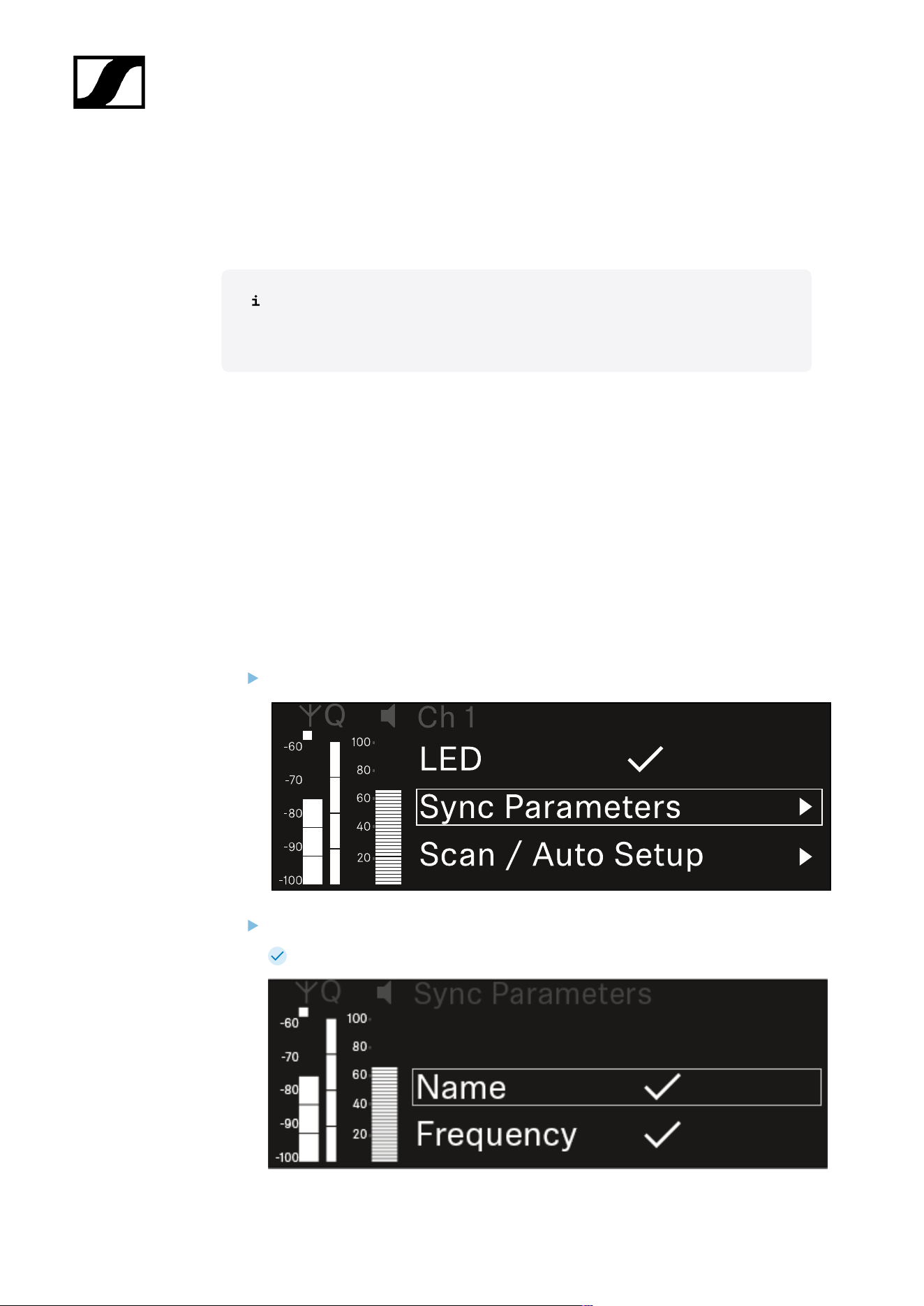
| 3 - Instruction manual
Ch 1 - Ch 4 -> Sync Parameters menu item
In the Sync Parameters menu item, you can choose which settings for the transmitter you
want to transfer from the receiver to the transmitter during the synchronization.
All of the settings can also be set separately in the menu on the transmitter.
During synchronization, the values set in the transmitter are overwritten with the
values set in the receiver.
The following parameters can be enabled or disabled for transmission.
• Name
• Frequency
• Trim
• Low Cut
• Cable Emul.
• Mute Mode
• Auto Lock
• LED
To open the Sync Settings menu item:
In the menu, navigate to the Sync Settings menu item for the desired channel.
Press the jog dial to open the menu.
The following view is displayed:
339

| 3 - Instruction manual
Turn the jog dial to choose between the options.
Press the jog dial to open your selected option.
For each option, select whether it will be synchronized or not.
The value set for this function will be transferred during synchronization.
The value set for this function will not be transferred during
synchronization.
Press the jog dial to save your setting.
340

| 3 - Instruction manual
Ch 1 - Ch 4 -> Scan/Auto Setup menu item
The receiver lets you scan the frequency spectrum and display all of the free frequencies in
the selected frequency range. The automatic frequency setup can be used to distribute the
free frequencies to all of the EW-DX EM 4 devices available in the network automatically.
Switch off all transmitters before you perform the scan.
If transmitters are still switched on, they are detected as unavailable frequencies
and the frequencies that are actually available cannot then be used.
To perform the automatic frequency setup for all devices in the network,
the Auto Setup function must be enabled in the receiver’s system menu:
System -> Auto Setup menu item
An EM that is performing one of the following actions will be excluded
from the frequency setup of another EM:
• Remote (full) scan
• Scan Me / Scan Network -> Autosetup
• Bonding
• TX Sync
• TX Update
• Device Update (if in progress)
To open the Scan / Auto Setup menu item:
In the menu, navigate to the Scan / Auto Setup menu item for the desired channel.
Press the jog dial to open the menu.
The following view is displayed:
341

| 3 - Instruction manual
Turn the jog dial to choose between the Scan Me and Scan Network options.
• Scan Me: The frequency scan and the frequency setup are performed only for
the selected receiving channel.
• Scan Network: The frequency scan and the frequency setup are performed for
both channels of the receiver as well as for all other receivers available in the
network.
Press the jog dial to open your selected option.
Select a frequency from which to start the scan.
Press the jog dial to start the scan.
The spectrum is scanned for free frequencies above the selected frequency.
After the scan free frequencies are displayed, which you can then assign
to the channels.
342

| 3 - Instruction manual
Press the jog dial to assign the free frequencies to the receiving channels.
Or
Press the ESC key to cancel and not assign new frequencies.
Next, synchronize the receiving channels with the corresponding transmitters to
establish the radio link at the new selected frequencies (Synchronizing the receiver
and transmitter).
343
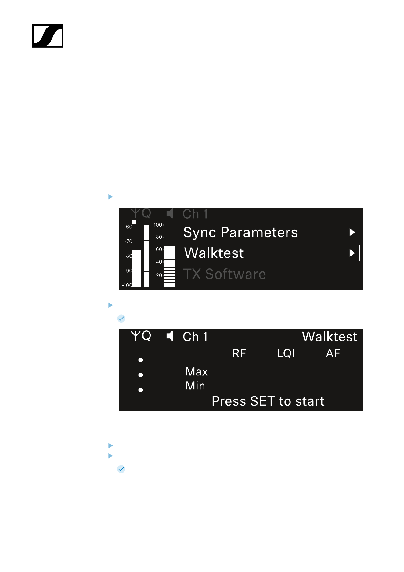
| 3 - Instruction manual
Ch 1- Ch 4 -> Walktest menu item
The Walktest menu item allows the performance of a reception test.
Once you have set up and installed all of the receivers and transmitters for your event, we
recommend performing a walk test. This lets you check whether sufficient reception strength
is available throughout the entire area used.
Start the walktest function in this menu item and then walk the entire area with one
transmitter. The results of the walk test give you information about the reception quality.
Opening the Walktest menu item
In the menu, navigate to the Walktest menu item for the desired channel.
Press the jog dial to open the menu.
The following view is displayed:
To start the reception test:
Press the jog dial.
Walk the entire area on which you want to operate the system with the transmitter.
The following values are recorded on the display:
• RF: Reception from antenna in dBm
• LQI: Connection quality as a %, see Meaning of the Link Quality Indicator
• AF: Transmitter audio frequency in dBFS
344

| 3 - Instruction manual
To end the reception test:
Press the Jog-Dial to finish the walk test when you are ready.
345
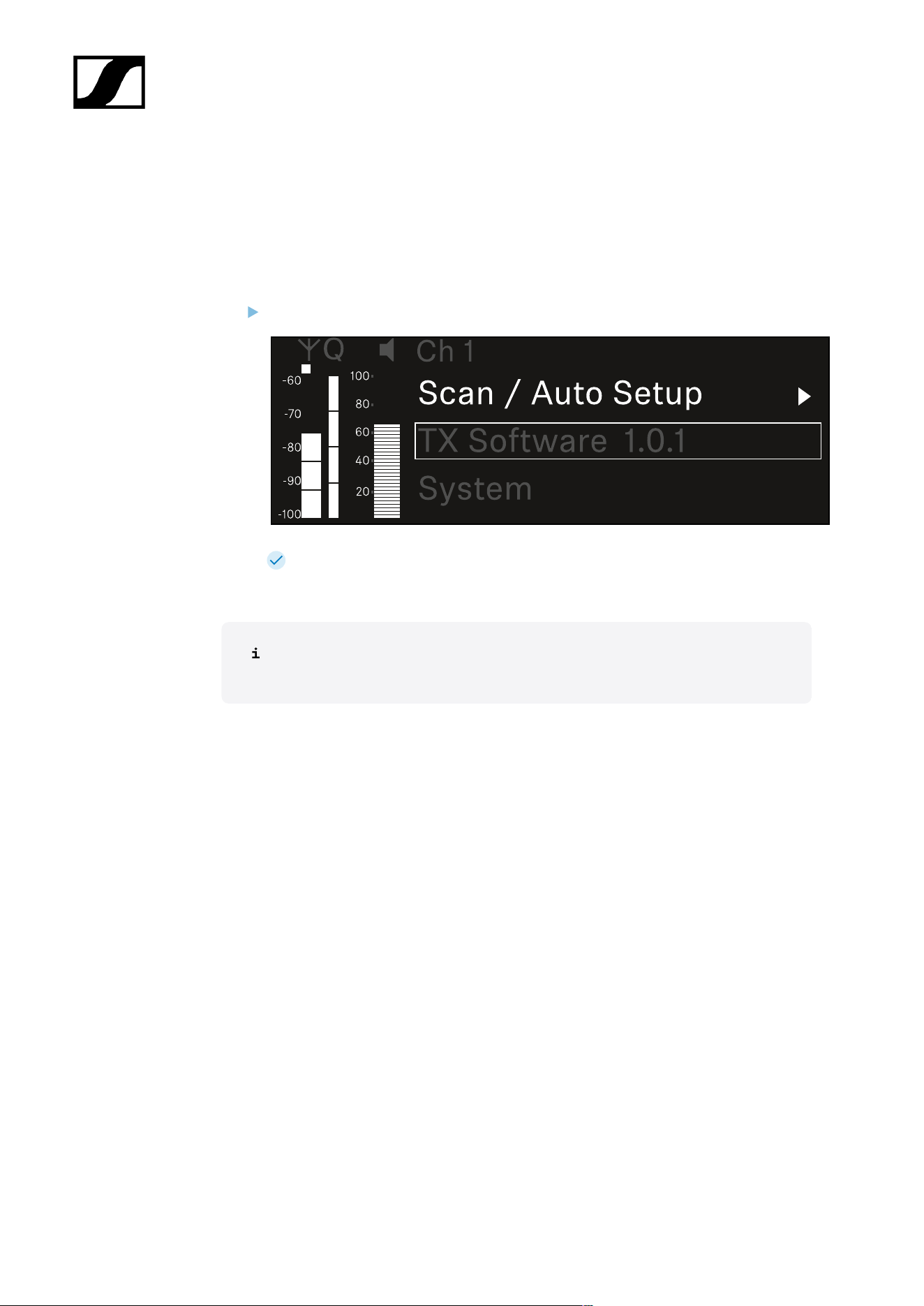
| 3 - Instruction manual
Ch 1 - Ch 4 -> TX Software menu item
The TX Software menu item displays the software version of the received transmitter.
You cannot open this menu item to make settings.
In the menu, navigate to the TX Software menu item for the desired channel.
The version number of the transmitter software is shown on the display. The
transmitter must be switched on for this to be displayed.
You can find information about updating the transmitter firmware in section
System -> TX Update menu item.
346

| 3 - Instruction manual
System menu item
In the System menu, you can make system-wide settings that will affect the entire device and
not only the respective receiving channel.
The following menu items are available:
Link Encryption
• This menu item lets you secure the radio link with AES 256 encryption.
• System -> Link Encryption menu item
Link Density
• In this menu item, you can set the required transmission mode.
• System -> Link Density menu item
Network
• In this menu item, you can configure the settings for the network connection.
• System -> Network menu item
TX Update
• This menu item lets you perform a firmware update for the transmitters.
• System -> TX Update menu item
Auto Setup
• This menu item allows you to activate automatic frequency setup for the receiver.
• System -> Auto Setup menu item
This Device
• This menu item allows you to enter a device name and display information about the
receiver’s hardware and software.
• System -> This Device menu item
System -> Link Encryption menu item
You can secure the radio link between the transmitter and receiver using AES 256
encryption.
347

| 3 - Instruction manual
To open the Link Encryption menu item:
In the System menu, navigate to the Link Encryption menu item.
Press the jog dial to open the menu.
The following view is displayed:
Turn the jog dial to choose between the On and Off options.
Press the jog dial to save your setting.
After enabling AES 256 encryption, the connected transmitter must be
resynchronized with the receiver to enable encryption on the transmitter as well.
348

| 3 - Instruction manual
System -> Link Density menu item
Link Density mode (LD mode)
LD mode doubles the number of usable carrier frequencies in the available
spectrum, as the minimum distance for the equidistant frequency grid is halved.
This is achieved by reducing the modulation bandwidth of the transmitter. This
means that a much smaller frequency spacing between neighboring frequencies
can be selected, and therefore more frequencies can be used in the same
available spectrum without intermodulation.
LD mode is recommended if the following criteria are met:
• The required number of channels cannot be achieved using the normal
mode, as there may be only a small spectrum available.
• The distance between the transmitters and the antennas is not too great.
To open the Link Density menu item:
In the System menu, navigate to the Link Density menu item.
Press the jog dial to open the menu.
The following view is displayed:
Turn the jog dial to choose between the On and Off options.
Press the jog dial to save your setting.
349
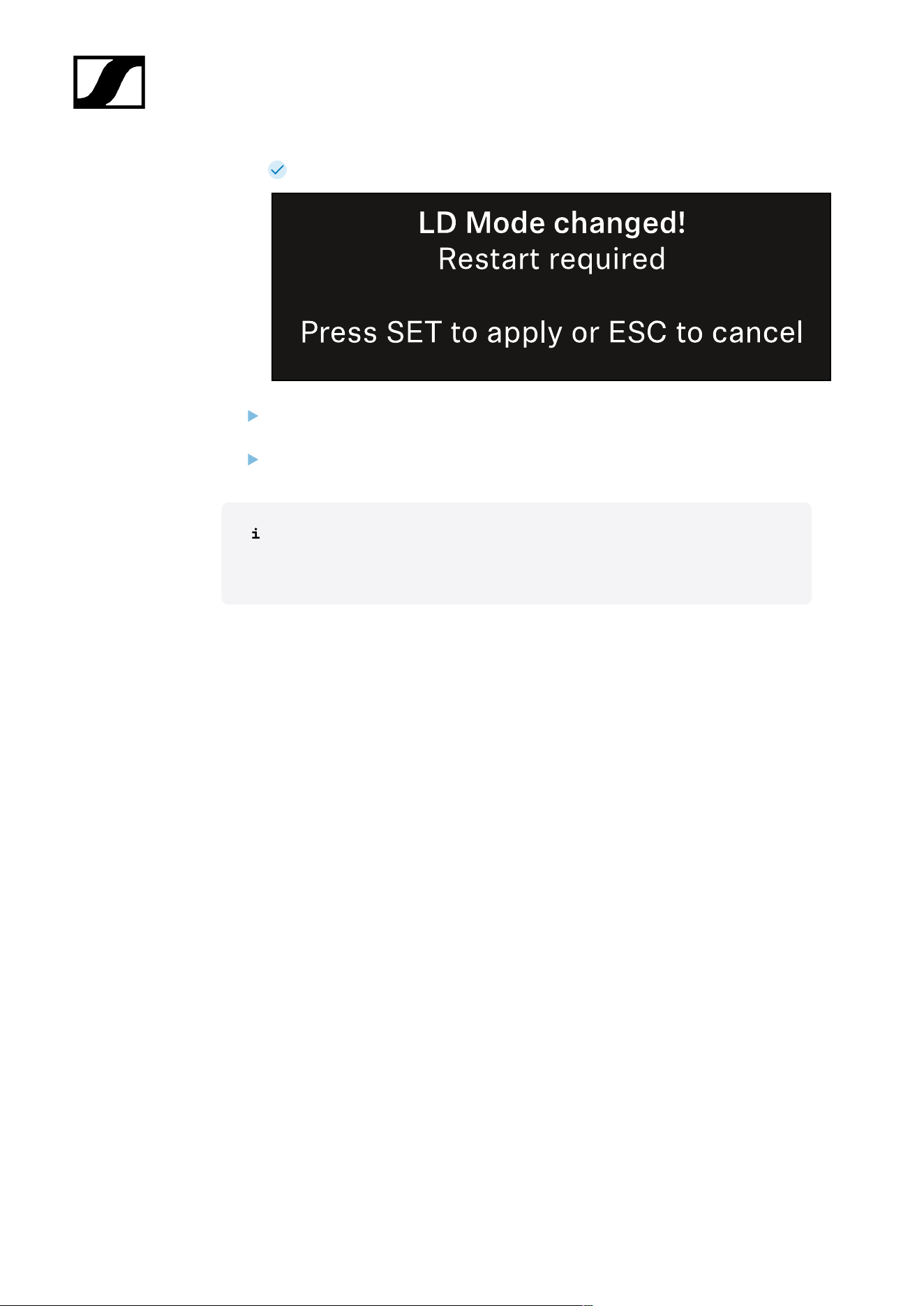
| 3 - Instruction manual
If you have enabled LD mode, the receiver must be restarted.
Press the jog dial to restart the receiver.
Or
Press the ESC button to cancel the mode change.
After enabling LD mode and restarting the receiver, the connected transmitter
must be resynchronized with the receiver to enable LD mode on the transmitter
as well.
350
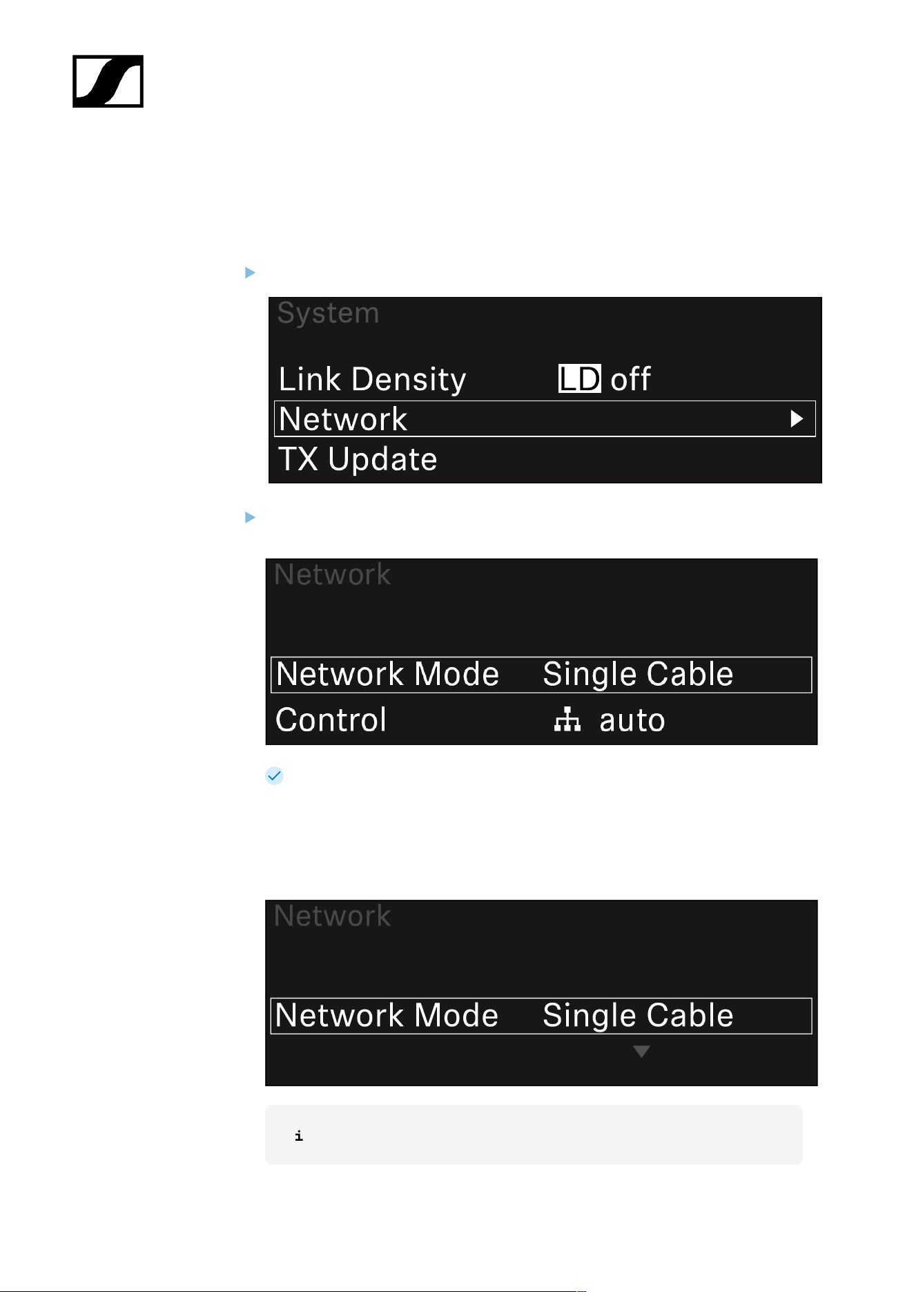
| 3 - Instruction manual
System -> Network menu item
In this menu item, you can configure the settings for the network connection.
To open the Network menu item:
In the System menu, navigate to the Network menu item.
Rotate the jog dial to navigate through the Network menu and select the desired
menu item.
You can make the following settings here:
Network Mode
• Single Cable
• Split
• Redundancy
See Connecting receivers in a Dante® network.
351

| 3 - Instruction manual
Control
• Mode
• Auto: The network configuration is performed automatically.
• Manual: The network configuration can be performed manually.
• mDNS
• You can enable or disable this option if you want to use mDNS for
automatic device detection in the network.
• IP
• If the Mode option is set to Auto, the automatically assigned IP
address is displayed here.
• If the Mode option is set to Manual, you can set the IP address here.
• Netmask
• If the Mode option is set to Auto, the automatically assigned netmask
is displayed here.
• If the Mode option is set to Manual, you can set the netmask here.
• Gateway
• If the Mode option is set to Auto, the automatically assigned gateway
is displayed here.
• If the Mode option is set to Manual, you can set the gateway here.
Dante - Dante Primary and Dante Secondary
• Mode
• Auto: The network configuration is performed automatically.
• Manual: The network configuration can be performed manually.
• mDNS
• You can enable or disable this option if you want to use mDNS for
automatic device detection in the network.
• IP
• If the Mode option is set to Auto, the automatically assigned IP
address is displayed here.
• If the Mode option is set to Manual, you can set the IP address here.
• Netmask
• If the Mode option is set to Auto, the automatically assigned netmask
is displayed here.
• If the Mode option is set to Manual, you can set the netmask here.
• Gateway
• If the Mode option is set to Auto, the automatically assigned gateway
is displayed here.
• If the Mode option is set to Manual, you can set the gateway here.
352
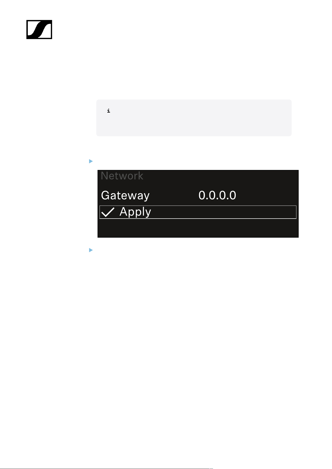
| 3 - Instruction manual
Spanning Tree (STP)
• If the option is enabled, misconfigurations between network modes and
cabling is avoided.
• If the option is disabled, broadcast storms may result.
• By default and after a factory reset, STP is enabled.
The Spanning Tree is configured with a priority of 57344 and should be
considered when setting up a network with managed switch so that an
EW-DX EM doesn't get the route bridge.
To save the settings you have made:
Turn the jog dial until Apply appears in the selection frame.
Press the jog dial to save your settings.
353
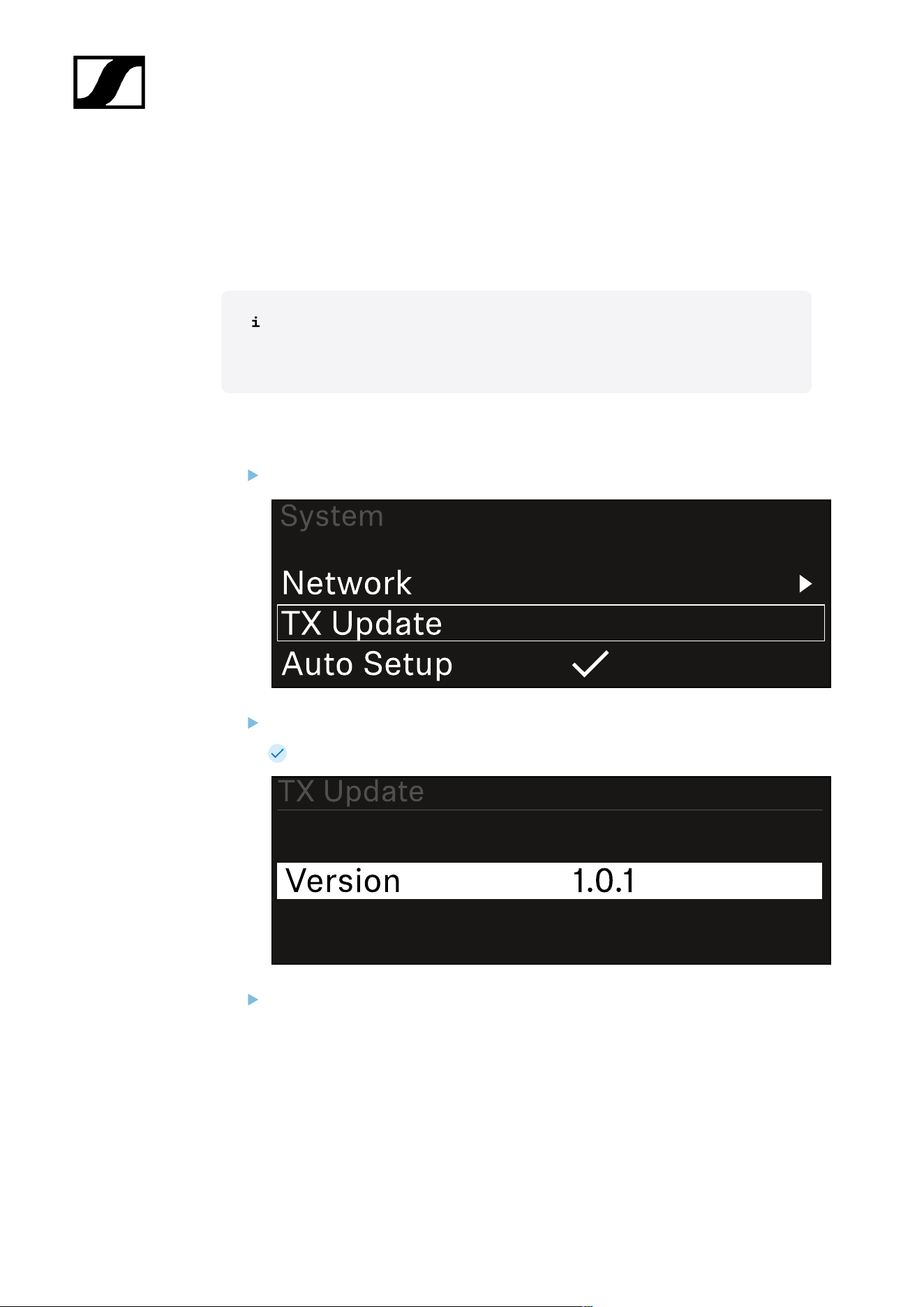
| 3 - Instruction manual
System -> TX Update menu item
This menu item lets you perform a firmware update for the transmitters. This update is
recommended after you perform a firmware update for the receiver (see Updating the
firmware of the receiver).
The firmware versions currently installed on the connected transmitter can be
viewed under the TX Software menu item for the respective channel (see Ch 1 -
Ch 4 -> TX Software menu item).
To open the TX Update menu item:
In the System menu, navigate to the TX Update menu item.
Press the jog dial to open the menu.
The available sender firmware is displayed:
Press the jog dial to start the firmware update.
354
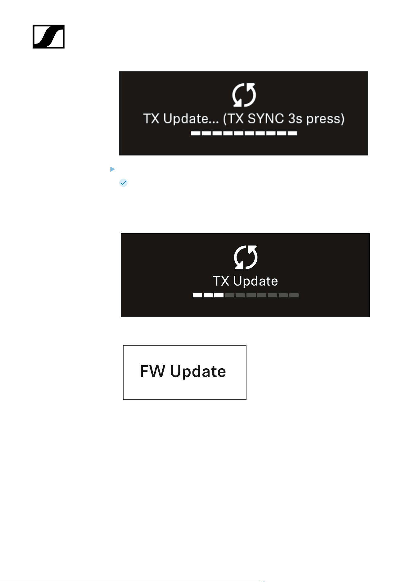
| 3 - Instruction manual
Press the SYNC button on the connected transmitter for 3 seconds.
You have about 20 seconds to do this. The progress bar shows the remaining
time.
The system carries out the firmware update for the transmitter.
The progress of the update is shown on the receiver’s display.
The transmitter’s display shows that the firmware update is in progress.
355

| 3 - Instruction manual
NOTICE
Canceling the update can impair the function of the transmitter
If the transmitter is turned off during the firmware update, the update
may fail and the transmitter may cease to function correctly.
Do not turn off the transmitter during the update.
Do not remove the batteries or rechargeable battery pack during
the update.
Make sure that the transmitter’s (rechargeable) batteries are
sufficiently charged before updating.
356

| 3 - Instruction manual
System -> Auto Setup menu item
In this menu item, you can activate the Auto Setup function for the receiver.
If the function is activated here, you can perform an automatic frequency setup for both
channels of this receiver via the Scan / Auto Setup menu item.
See Ch 1 - Ch 4 -> Scan/Auto Setup menu item.
The receiver will also be enabled for automatic frequency setup in a network consisting of
multiple receivers.
If the function is disabled here, you can only assign a frequency to the selected channel of
the receiver via the Scan / Auto Setup menu item.
To open the Auto Setup menu item:
In the System menu, navigate to the Auto Setup menu item.
Press the jog dial to open the menu.
The following view is displayed:
Turn the jog dial to choose between the On and Off options.
Press the jog dial to save your setting.
357
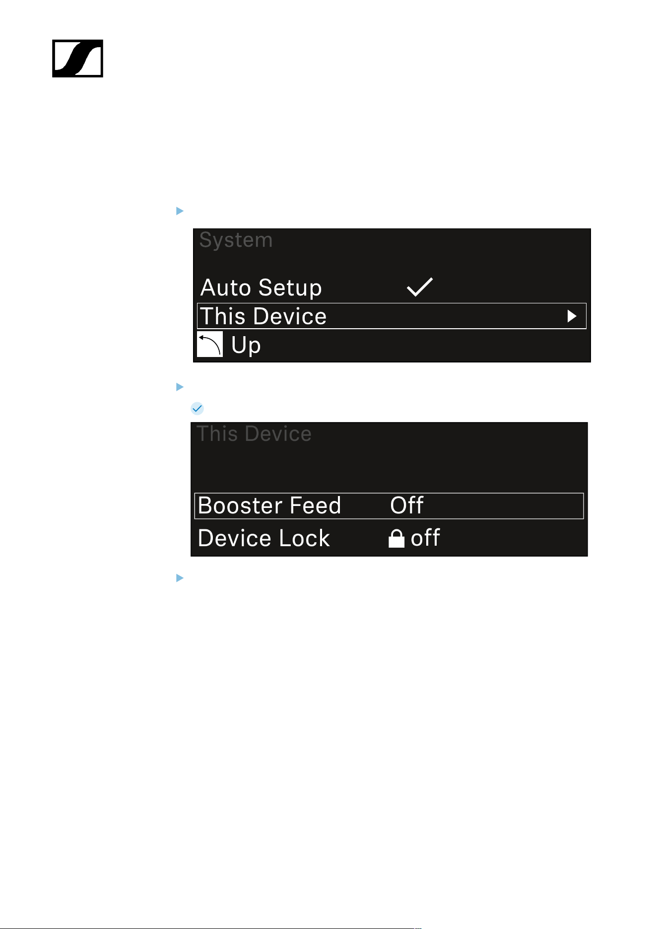
| 3 - Instruction manual
System -> This Device menu item
This menu item allows you to change the device name, view software and hardware
information, or reset the device to factory settings.
To open the This Device menu item:
In the System menu, navigate to the This Device menu item.
Press the jog dial to open the menu.
The following view is displayed:
Choose from the following:
• Booster Feed: Set the power supply for an external antenna amplifier
• Device Lock: Set the lock-off of the receiver.
• Brightness: Set the brightness of the display.
• Device Name: Open this menu item to change the device name. This receiver
will be displayed in the network under this name.
• MAC: Shows the MAC address of the receiver.
• Dante Name: Shows the name of the device in the Dante network.
• Dante Pri MAC/Dante Sec MAC: Shows the primary/secondary Dante MAC
address of the receiver
• Software: Shows the software version of the receiver.
• HW Main/HW Front/HW Tuner1/HW Tuner 2/HW Interface: Displays the
hardware versions of the boards installed in the receiver.
358

| 3 - Instruction manual
• Reset:
• Audio Ch1 | Audio Ch2 | Audio All (EW-DX EM 2 / EW-DX EM 2
Dante): resets selected audio channel settings or all audio channel
settings to their default.
• Audio Ch1 | Audio Ch2 | Audio Ch3 | Audio Ch4 | Audio All (EW-
DX EM 4 Dante): resets selected audio channel settings or all audio
channel settings to their default.
• Network: resets the network settings and the claiming password to
their factory settings.
• Factory: resets the receiver to factory settings.
359

| 3 - Instruction manual
Updating the firmware of the receiver
You can update the receiver firmware using the Sennheiser Control Cockpit software, the
Wireless Systems Manager software or the Smart Assist app.
Updating with the Sennheiser Control Cockpit or the Wireless Systems Manager:
Connect the receiver to a network (see Connecting receivers in a network) and
establish the connection with the software.
For more information about controlling devices with the Sennheiser
Control Cockpit or Wireless Systems Manager software, refer to the
software help.
You can download the software here:
sennheiser.com/scc
sennheiser.com/wsm
To update the transmitter’s firmware, go to System -> TX Update in the
menu on the receiver. See System -> TX Update menu item
Updating with the Smart Assist app:
Connect the receiver to a network (see Connecting receivers in a network).
Connect a wireless access point to the network.
Connect your smartphone to this network.
Start the update process in the Smart Assist app:
Click on “Update” if the device is on the network.
Follow the instructions.
Or
Search for devices that can be updated.
Follow the instructions.
360
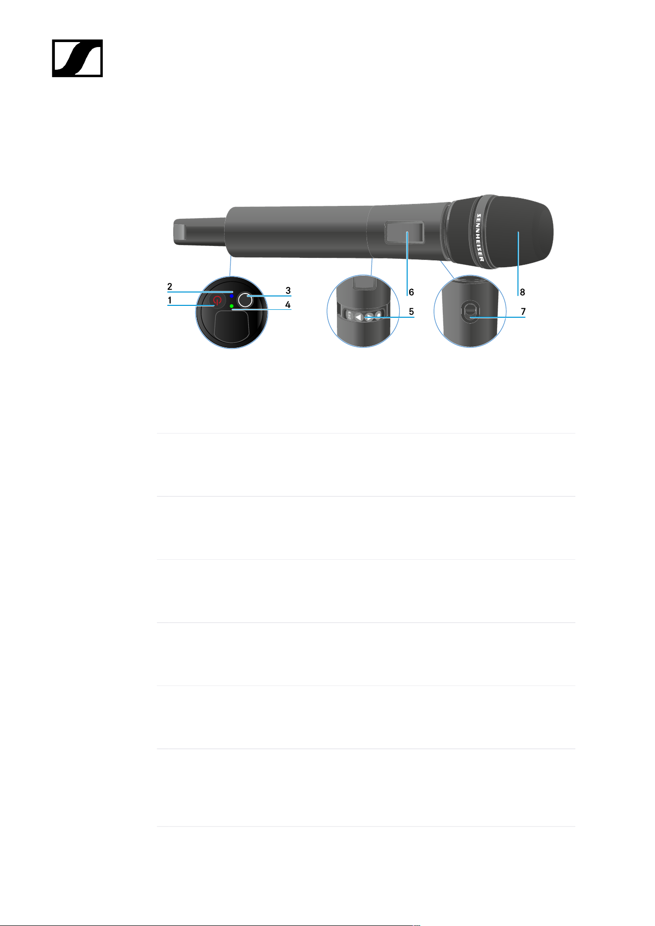
| 3 - Instruction manual
EW-DX SKM | EW-DX SKM-S handheld transmitter
Product overview
1 ON/OFF button
• See Switching the handheld transmitter on and off
2 DATA LED
• See Meaning of the LEDs
3 SYNC button
• See Establishing a connection to the receiver
4 LINK LED
• See Meaning of the LEDs
5 Function buttons for navigating the menu
• See Buttons for navigating the menu
6 Display panel
• See Information on the handheld transmitter’s display
7 Mute switch (EW-DX SKM-S only)
• See Configuring mute mode and muting the handheld transmitter (EW-DX
SKM-S only)
361

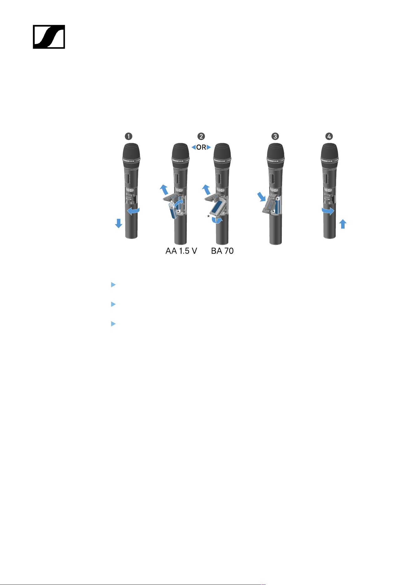
| 3 - Instruction manual
Inserting and removing the batteries/rechargeable batteries
You can operate the handheld transmitter either with batteries (AA, 1.5 V) or with the
rechargeable Sennheiser BA 70 battery.
Unscrew the microphone housing as shown in the figure and pull it down as far as it
will go.
Insert the batteries or the BA 70 rechargeable battery as indicated in the battery
compartment. Observe correct polarity.
Screw the microphone housing back on.
363

| 3 - Instruction manual
Note about the BA 70 rechargeable battery
• Make sure that the BA 70 rechargeable battery is inserted as follows:
364

| 3 - Instruction manual
Replacing the microphone module
To replace the microphone module:
Unscrew the microphone module.
Screw the desired microphone module on.
Do not touch the wireless microphone contacts or the microphone module contacts. If
you touch the contacts, they may become dirty or bent.
Compatible microphone modules
The following microphone modules are compatible with the handheld transmitter:
• MMD 835-1 | Dynamic microphone module with cardioid pattern
• MMD 845-1 | Dynamic microphone module with super-cardioid pick-up pattern
• MME 865-1 | Condenser microphone module with super-cardioid pick-up pattern
• MMD 935-1 | Dynamic microphone module with cardioid pattern
• MMD 945-1 | Dynamic microphone module with super-cardioid pick-up pattern
• MMK 965-1 | Condenser microphone module with selectable pattern: cardioid and
super-cardioid
• MMD 42-1 | Dynamic microphone module with omni-directional pattern
• Neumann KK 204 | Condenser microphone module with cardioid pattern
365

| 3 - Instruction manual
• Neumann KK 205 | Condenser microphone module with super-cardioid pick-up
pattern
• MM 435 | Dynamic microphone module with cardioid pattern
• MM 445 | Dynamic microphone module with super-cardioid pick-up pattern
• ME 9002 | Condenser microphone module with omni-directional pattern
• ME 9004 | Condenser microphone module with cardioid pattern
• ME 9005 | Condenser microphone module with super-cardioid pick-up pattern
366
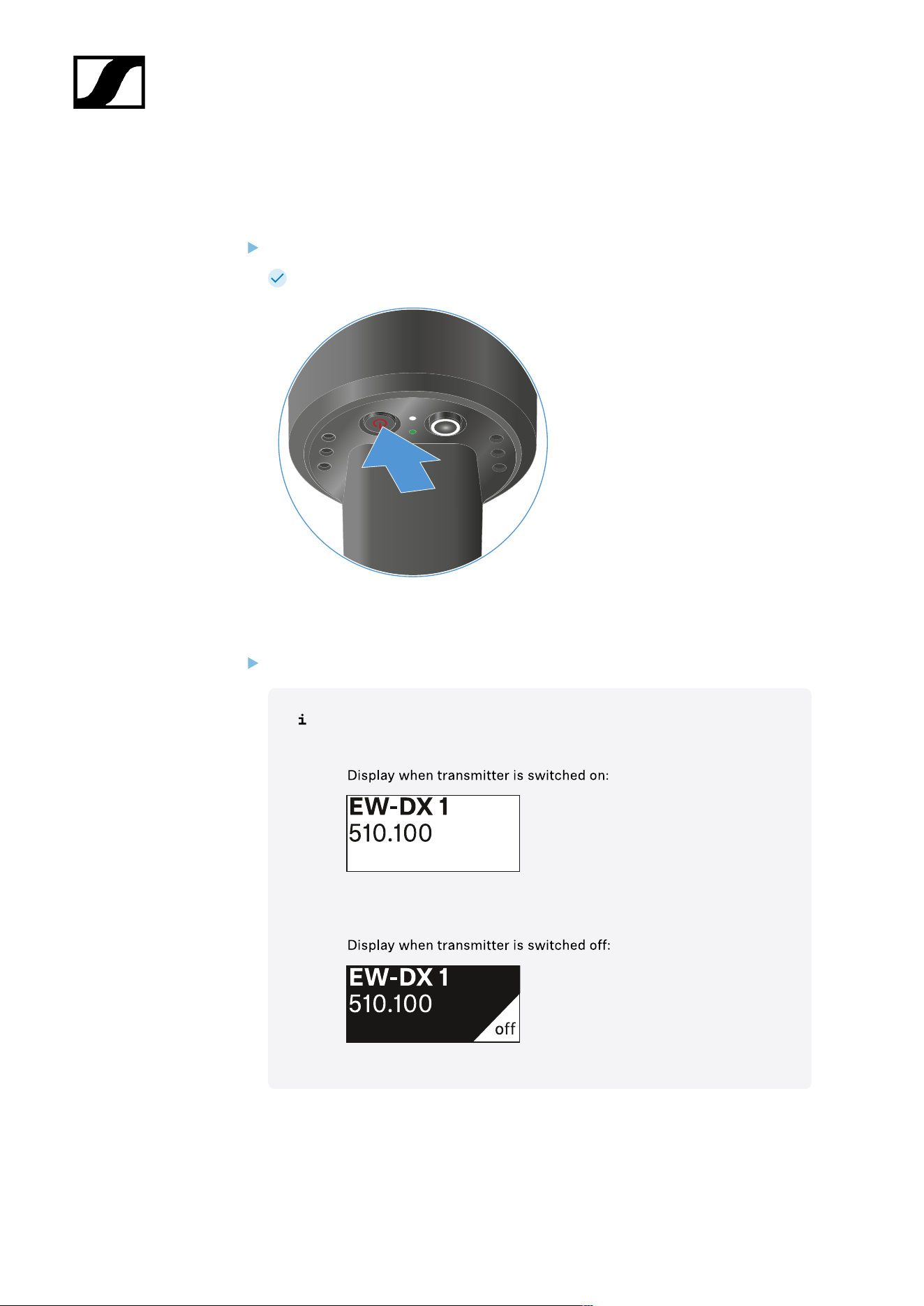
| 3 - Instruction manual
Switching the handheld transmitter on and off
To switch the handheld transmitter on:
Short-press the ON/OFF button.
The LINK LED lights up and the transmitter switches on.
To switch the handheld transmitter off:
Hold down the ON/OFF button until the LEDs switch off.
Note that the transmitter’s permanent E-Ink display still displays the
parameters after it is switched off.
367
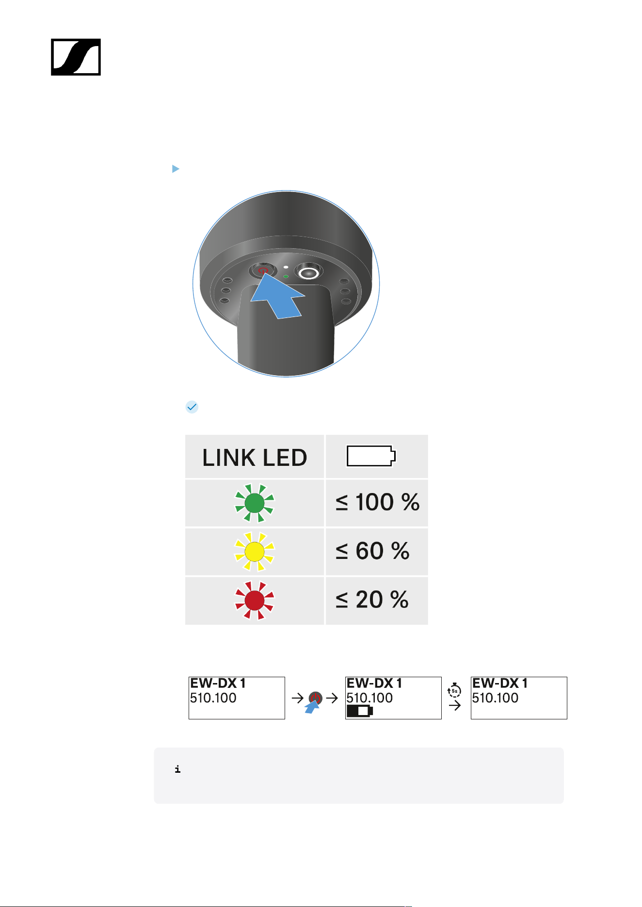
| 3 - Instruction manual
Checking the battery status of the transmitter (Check function)
Checking the battery status of the transmitter
Short-press the ON/OFF button on the transmitter.
The transmitter’s LINK LED flashes to indicate the current charge level of the
battery or the BA 70 rechargeable battery.
In addition, the battery status is displayed on the transmitter display for approx. 5
seconds.
Pressing the transmitter’s ON/OFF button will simultaneously trigger the Identify
function: Identifying the paired receiver (Identify function).
368
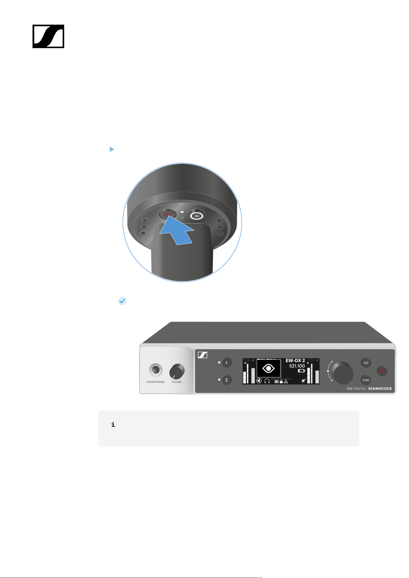
| 3 - Instruction manual
Identifying the paired receiver (Identify function)
In multi-channel systems, you can use the Check function to quickly identify to which
receiver the transmitter is paired.
Both the transmitter and receiver must be switched on.
Short-press the ON/OFF button on the transmitter.
An eye flashes next to the respective receiving channel on the coupled receiver’s
display.
Pressing the transmitter’s ON/OFF button will simultaneously trigger the Check
function: Checking the battery status of the transmitter (Check function).
369
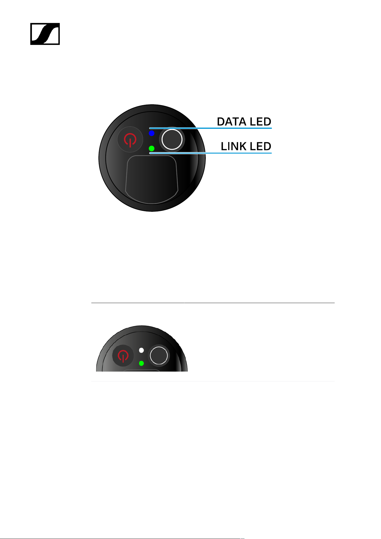
| 3 - Instruction manual
Meaning of the LEDs
The LINK and DATA LEDs on the bottom of the transmitter can indicate the following
information.
LINK LED
The LINK LED provides information about the status of the radio link between the transmitter
and receiver, as well as status information for the paired transmitter.
The LED is green:
• The link between the transmitter and receiver is
established.
• The transmission frequency is active.
The LED is yellow:
• The link between the transmitter and receiver is
established.
• The audio signal is muted or
• No microphone module is mounted on the
SKM-S handheld transmitter.
370
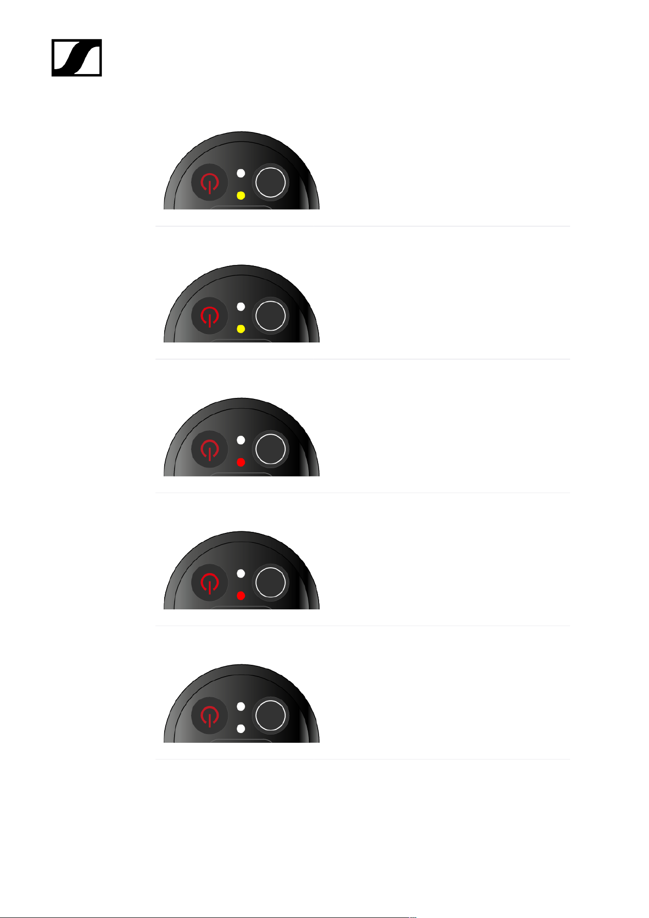
| 3 - Instruction manual
The LED is flashing yellow:
• The link between the transmitter and receiver is
established.
• The audio signal is overdriven (clipping).
The LED is continuously red:
• The (rechargeable) battery in the transmitter is
dead.
The LED is flashing red:
• The link between the transmitter and receiver is
established.
• The battery/rechargeable battery in the
transmitter is low.
The LED is off:
• No link between the transmitter and receiver.
• The transmitter is switched off.
DATA LED
The DATA LED provides information about the synchronization of transmitters and receivers.
371

| 3 - Instruction manual
The LED is flashing blue:
• The transmitter is being synchronized with a
receiver.
The LED is blue:
• The firmware is being updated.
The LED is off:
• There is currently no active data link.
372

| 3 - Instruction manual
Establishing a connection to the receiver
To establish a radio link between the transmitter and the receiver, the devices must be
synchronized.
See Establishing a radio link | Synchronizing the receiver and transmitter
Conditions and restrictions for using frequencies
There may be special conditions and restrictions for using frequencies in your
country.
Before putting the product into operation, find the information for your country
at the following address:
sennheiser.com/sifa
373

| 3 - Instruction manual
Information on the handheld transmitter’s display
You can view the following information on the transmitter display.
Link name
• You can assign a name to the radio link in the transmitter’s menu (see Name menu
item).
• Alternatively, you can assign the name in the receiver’s menu and then synchronize it
to the transmitter (see Ch 1 / Ch 2 -> Name menu item).
Frequency
• You can manually set the frequency of the radio link in the transmitter’s menu (see
Frequency menu item).
• The frequency of the radio link can also be set manually in the receiver’s menu (see
Ch 1 / Ch 2 -> Frequency menu item) or via the Auto Setup function (see Ch 1 / Ch 2
-> Scan / Auto Setup menu item) and then synchronized to the transmitter.
Battery status
• Displays the charging status of the batteries or the BA 70 battery pack.
• When using the BA 70 rechargeable battery, the remaining runtime is also displayed
in hours and minutes.
• The battery status is hidden in the display’s default state. Short-press the On/Off
button on the transmitter (Check function, see Checking the battery status of the
transmitter (Check function)) to display the battery status for approx. 5 seconds.
374

| 3 - Instruction manual
System icons
The transmitter’s mute switch is deactivated. See Mute Button menu item.
The Auto Lock function is activated. See Auto Lock menu item.
AES 256 encryption is enabled. See System -> Link Encryption menu
item.
Note that the transmitter’s permanent E-Ink display still displays the parameters
after it is switched off.
375
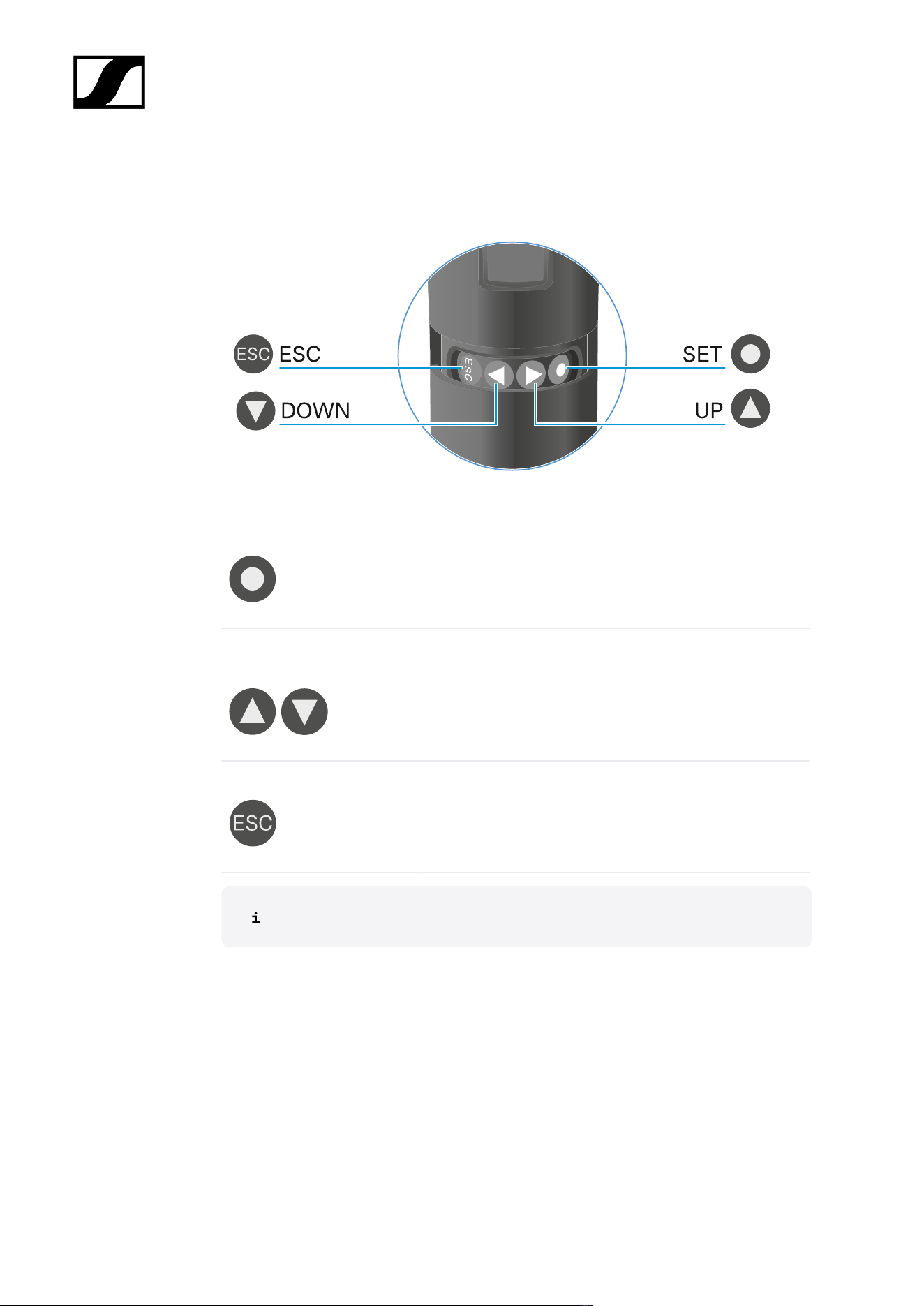
| 3 - Instruction manual
Buttons for navigating the menu
Use the following buttons to navigate through the transmitter’s operating menu.
Press the SET button
• Jumps from the home screen to the operating menu
• Calls up a menu item
• Saves settings
Press the UP or DOWN
button
• Changes to the previous or next menu item
• Changes the setting of a menu item
Press the ESC button
• Cancels the entry and returns to the previous
display
Opening the menu and navigating the menu items
376
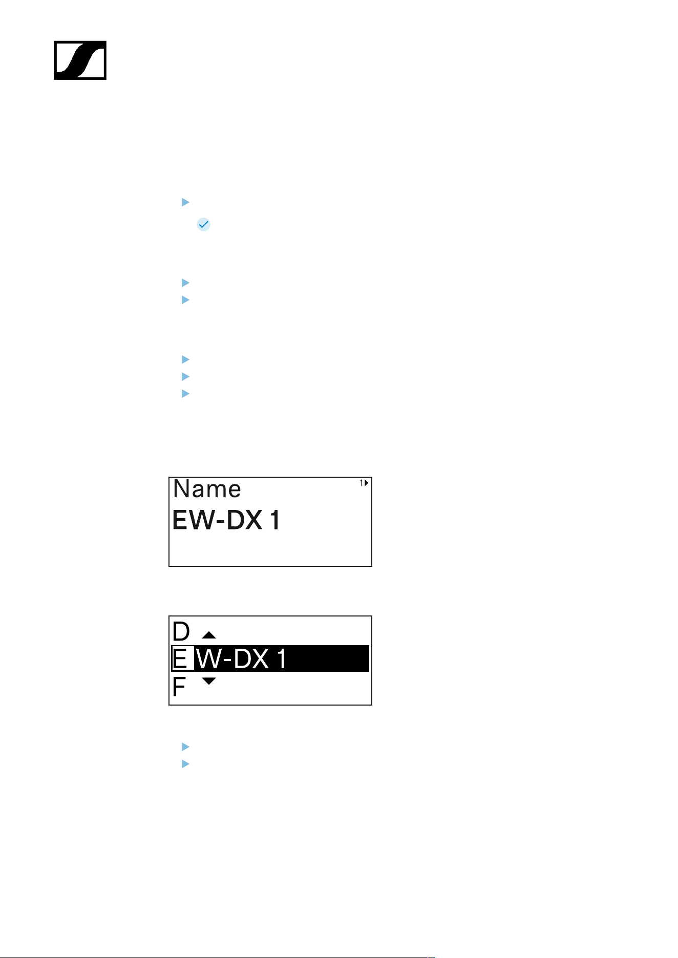
| 3 - Instruction manual
Opening the menu and navigating the menu items
Navigating through the menu and making changes in a menu item
To open the menu:
Press the SET button.
The operating menu is shown on the transmitter display panel.
To open a menu item:
Press the UP or DOWN buttons to navigate through the individual menu items.
Press the SET button to open the selected menu item.
To make changes in a menu item:
Press the UP or DOWN buttons to set the displayed value.
Press the SET button to save the setting.
Press the ESC button to leave the menu item without saving the setting.
Name menu item
You can enter the name of the link in this menu item.
Press the UP or DOWN buttons to select a character.
Press the SET button to go to the next position.
377

| 3 - Instruction manual
At the last position, press the SET button to save the selected name.
If you enter a name for the radio link in the Name menu item on the
receiver and then synchronize the receiving channel with the transmitter,
the name entered in the transmitter is overwritten with the name entered
in the receiver.
378
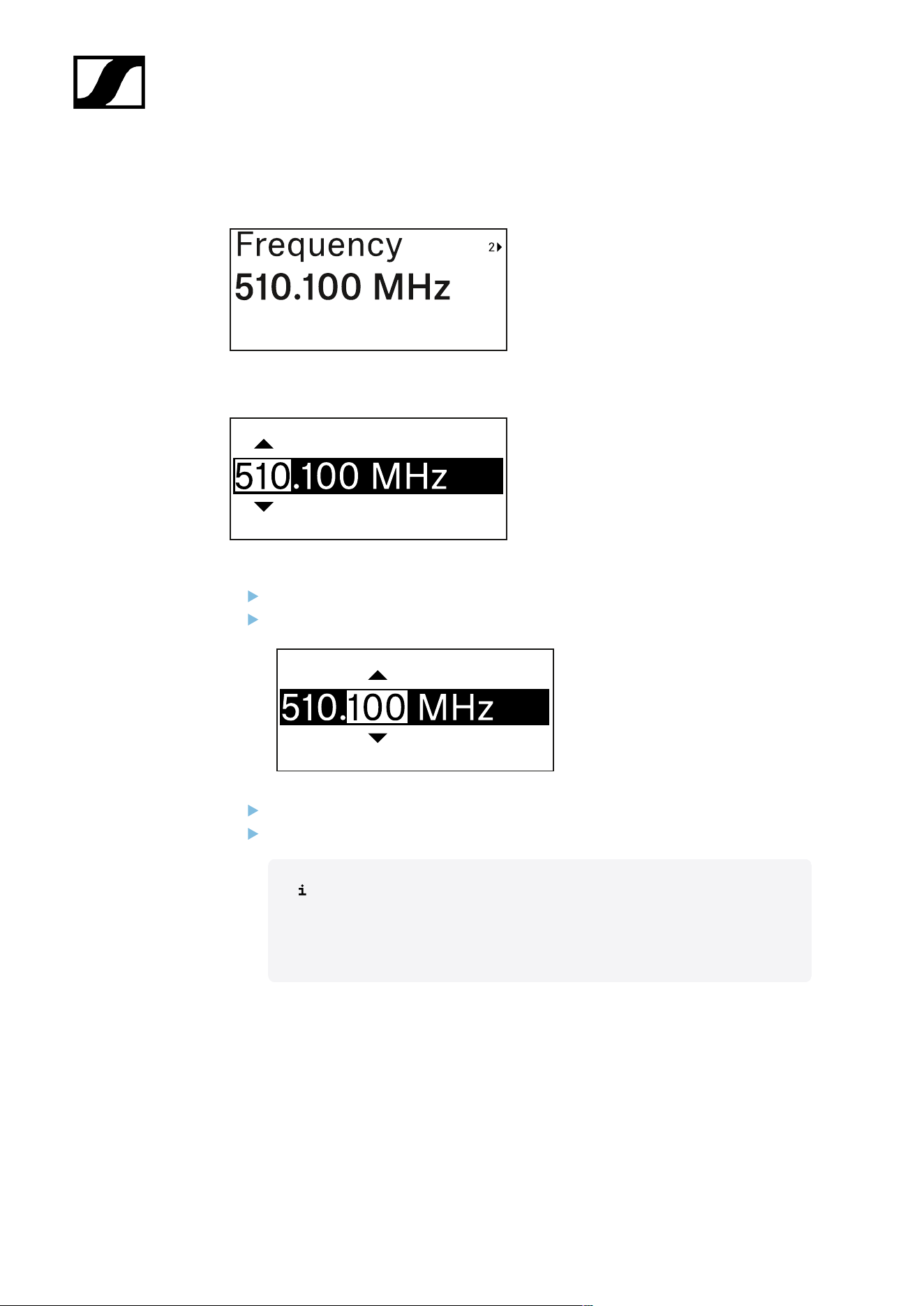
| 3 - Instruction manual
Frequency menu item
In this menu item, you can set the transmitter’s transmission frequency.
Press the UP or DOWN button to set the frequency’s MHz range.
Press the SET button to confirm your selection.
Press the UP or DOWN button to set the frequency’s kHz range.
Press the SET button to save the set frequency.
If you set a frequency for the channel using the Frequency menu item on
the receiver or via the Scan / Auto Setup function and then synchronize
the receiving channel with the transmitter, the frequency entered in the
transmitter is overwritten by the frequency set in the receiver.
379
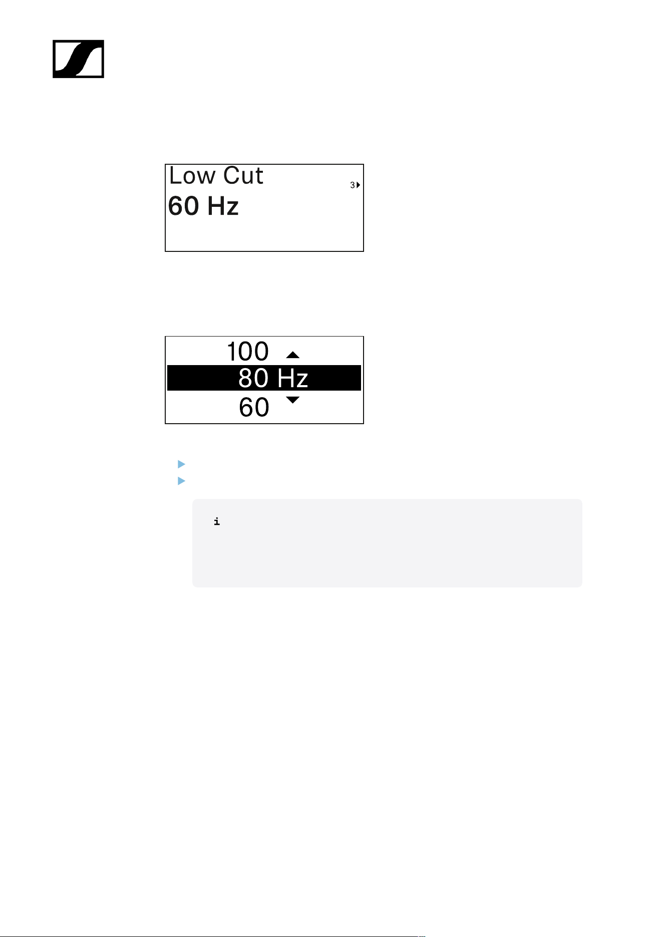
| 3 - Instruction manual
Low Cut menu item
In this menu item, you can adjust the value for the low cut filter.
• Setting range: 60 Hz, 80 Hz, 100 Hz, 120 Hz
Press the UP or DOWN button to set the desired value.
Press the SET button to confirm your selection.
If you set a value for the channel’s low cut filter using the Low Cut menu
item on the receiver and then synchronize the receiving channel with
the transmitter, the value entered in the transmitter is overwritten by the
value set in the receiver.
380
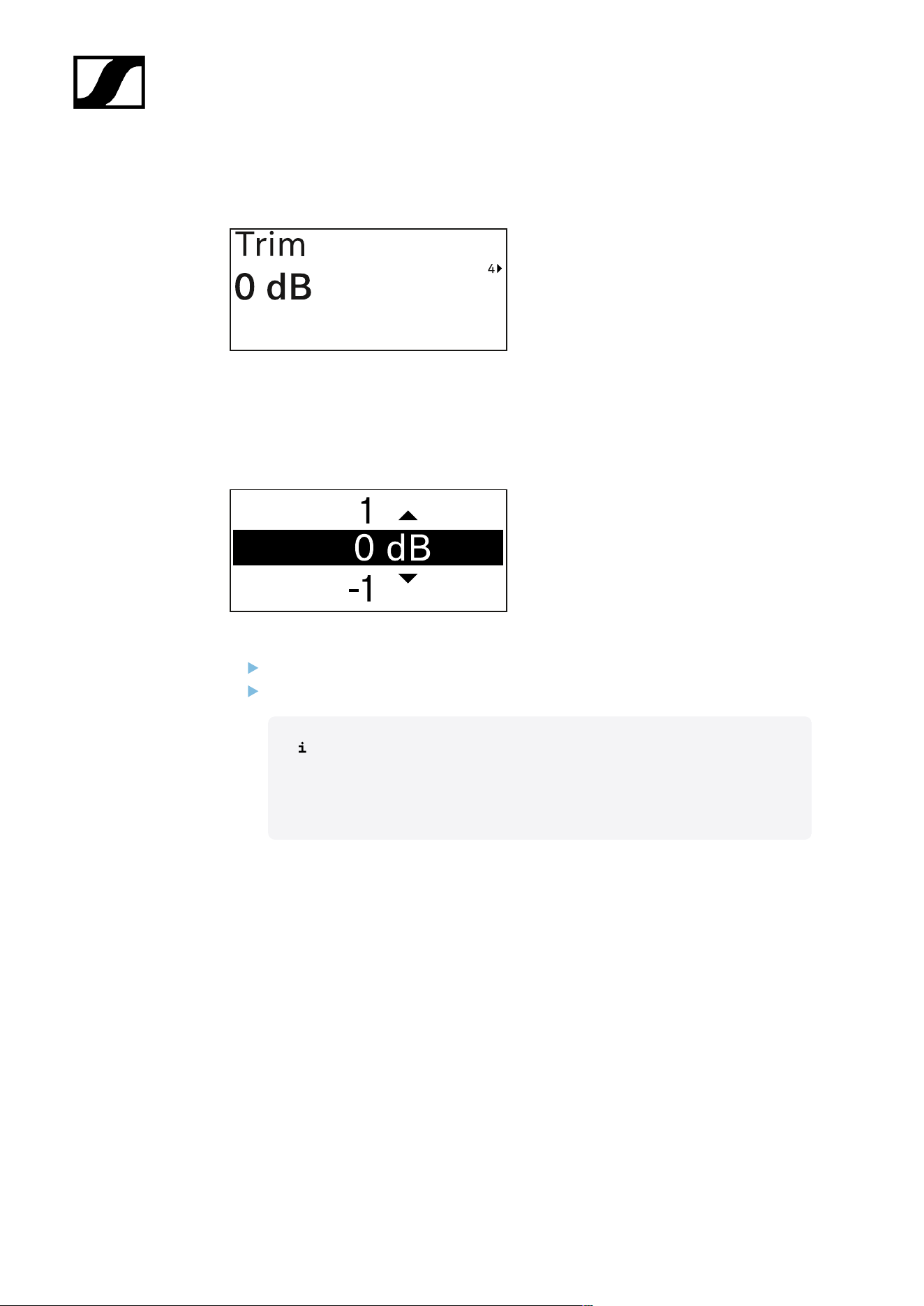
| 3 - Instruction manual
Trim menu item
In this menu item, you can adjust the audio level of the transmitter as well as the gain of the
wireless link (can be set only on the receiver) to suit input signals of different volumes.
• Setting range: -12 dB to +6 dB in increments of 1 dB
Press the UP or DOWN button to set the desired value.
Press the SET button to confirm your selection.
If you set a value for the channel in the Trim menu item on the receiver
and then synchronize the receiving channel with the transmitter, the value
entered in the transmitter is overwritten with the value entered in the
receiver.
381
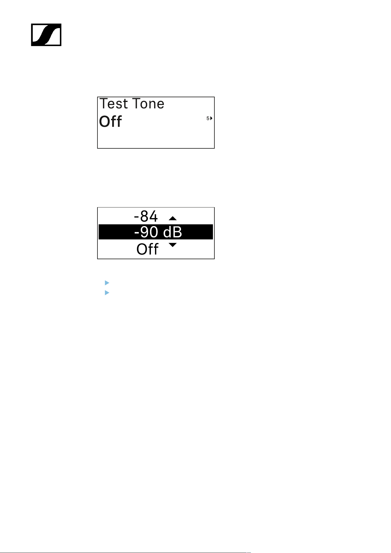
| 3 - Instruction manual
Test Tone menu item
In this menu item, you can activate a test tone that the transmitter transmits instead of the
input signal. You can use this feature to level out the system, for example.
• Setting range: Off, -90 dB to 0 dB in 6 dB increments
Press the UP or DOWN button to set the desired value.
Press the SET button to confirm your selection.
382
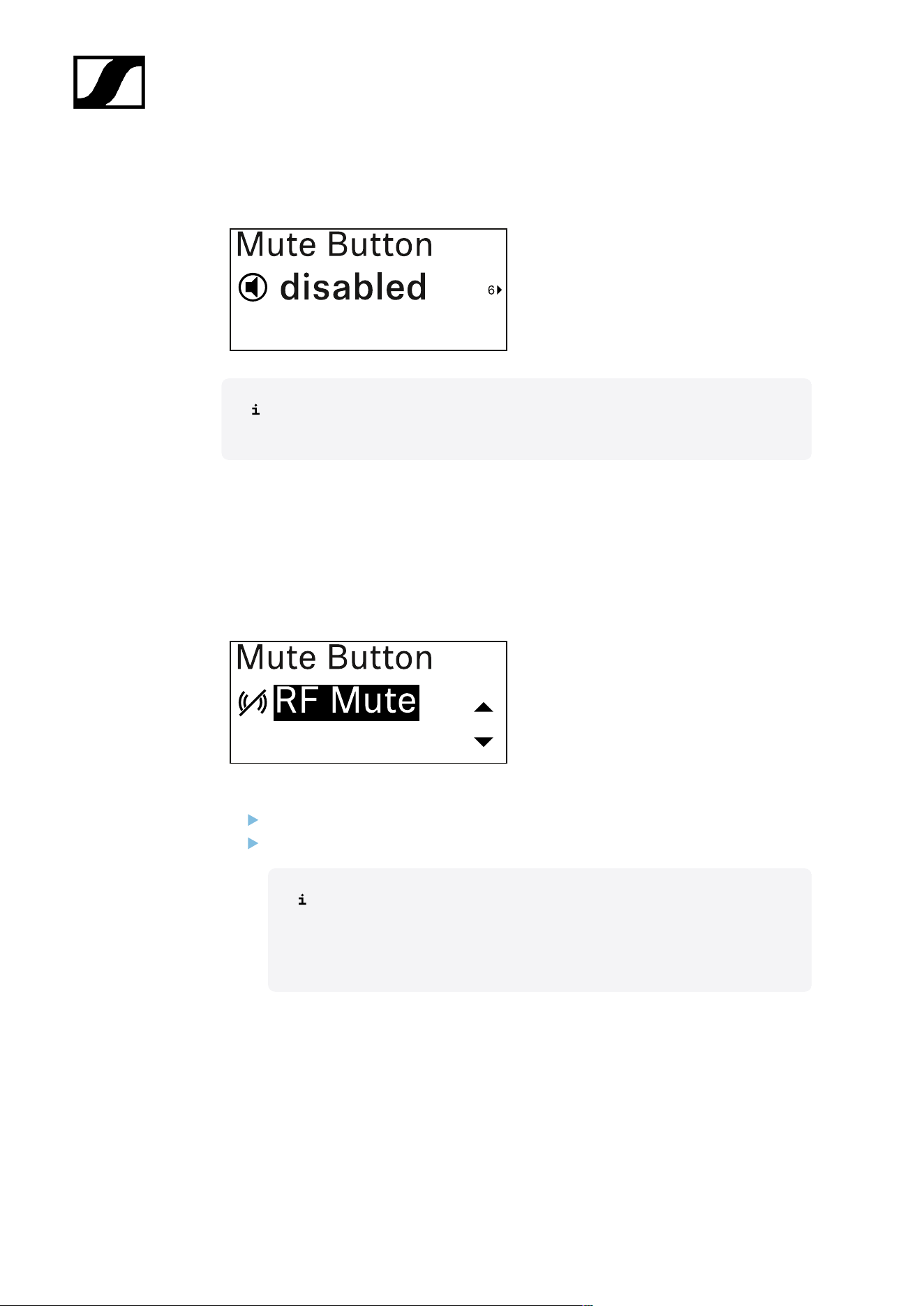
| 3 - Instruction manual
Mute Button menu item
This function is only available for the EW-DX SKM-S version, not for the EW-DX
SKM version.
In this menu item you can set the function of the transmitter’s mute switch.
Setting range:
• Disabled: The mute switch has no function.
• RF Mute: The RF signal is deactivated when the mute switch is on.
• AF Mute: The audio signal is muted when the mute switch is on.
Press the UP or DOWN button to set the desired value.
Press the SET button to confirm your selection.
If you set a function for the transmitter’s mute switch in the Mute Mode
menu item on the receiver and then synchronize the receiving channel
with the transmitter, the value entered in the transmitter is overwritten
with the value entered in the receiver.
383
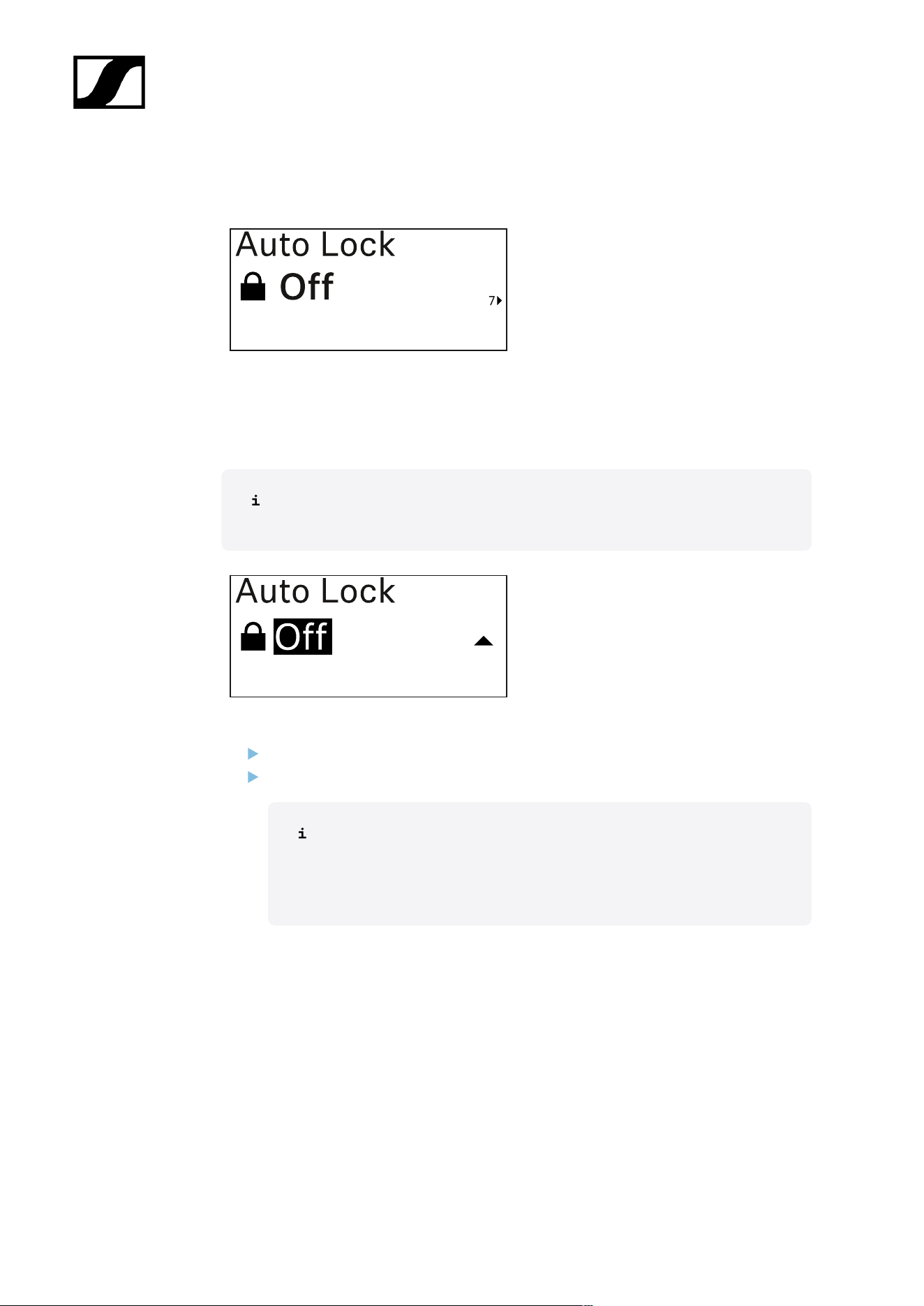
| 3 - Instruction manual
Auto Lock menu item
In this menu item, you can activate or deactivate the automatic lock-off for the transmitter.
The lock-off prevents the transmitter from being unintentionally switched off and also
prevents any changes to the transmitter’s menu.
The lock-off prevents the transmitter from being unintentionally switched off and
also prevents any changes to the transmitter’s menu. See Lock-off function.
Press the UP or DOWN button to set the desired value.
Press the SET button to confirm your selection.
If you set a value for the transmitter’s automatic lock-off in the Auto Lock
menu item on the receiver and then synchronize the receiving channel
with the transmitter, the value entered in the transmitter is overwritten
with the value entered in the receiver.
384
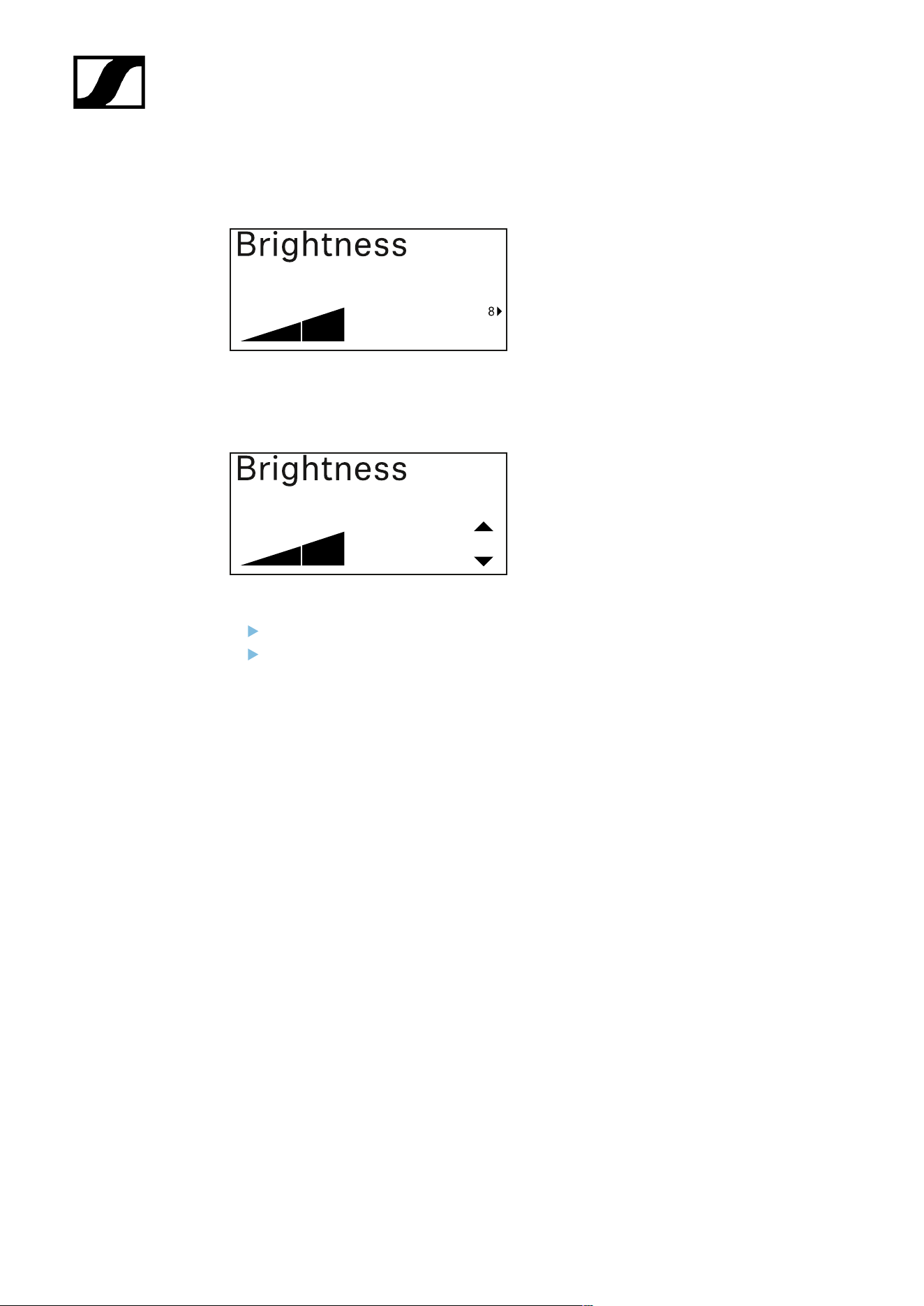
| 3 - Instruction manual
Brightness menu item
In this menu item, you can adjust the brightness of the transmitter’s display.
You can turn off the backlight completely or set it to one of five brightness levels.
Press the UP or DOWN button to set the desired value.
Press the SET button to confirm your selection.
385
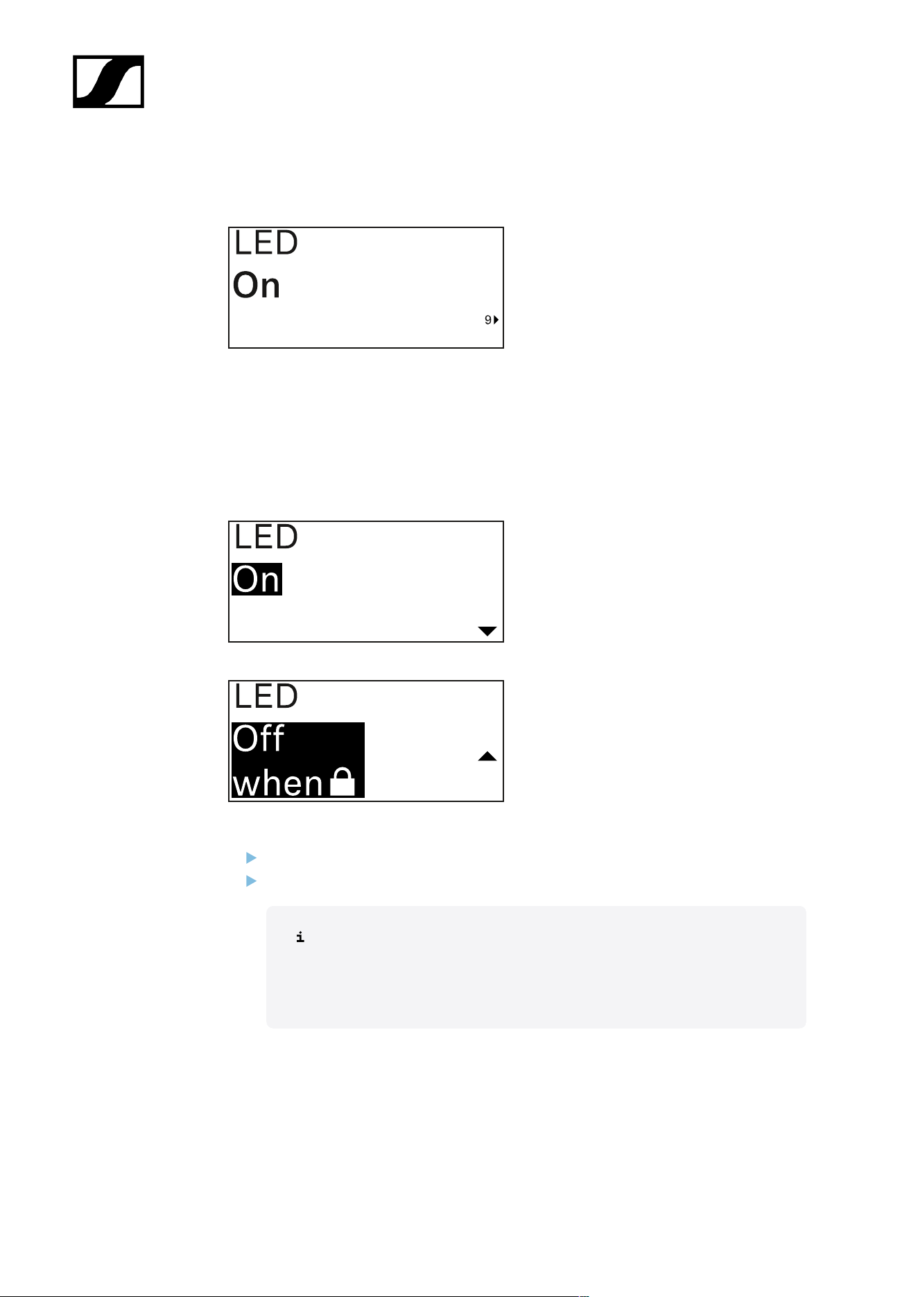
| 3 - Instruction manual
LED menu item
This menu item allows you to set the behavior of the transmitter’s LINK LED.
Setting range:
• ON: The LINK LED remains continuously lit.
• OFF: The LINK LED switches off while the lock-off function is active.
Press the UP or DOWN button to set the desired value.
Press the SET button to confirm your selection.
If you set a function for the transmitter’s LINK LED in the LED menu
item on the receiver and then synchronize the receiving channel with the
transmitter, the value entered in the transmitter is overwritten with the
value entered in the receiver.
386

| 3 - Instruction manual
This Device menu item
In this menu item you can view information about the transmitter’s software and hardware
and reset the transmitter to the factory settings.
Show software
Shore hardware
Reset to factory settings
387

| 3 - Instruction manual
Press the SET button to open the Reset menu item.
Press the UP or DOWN button to set the desired value.
Press the SET button to confirm your selection.
388
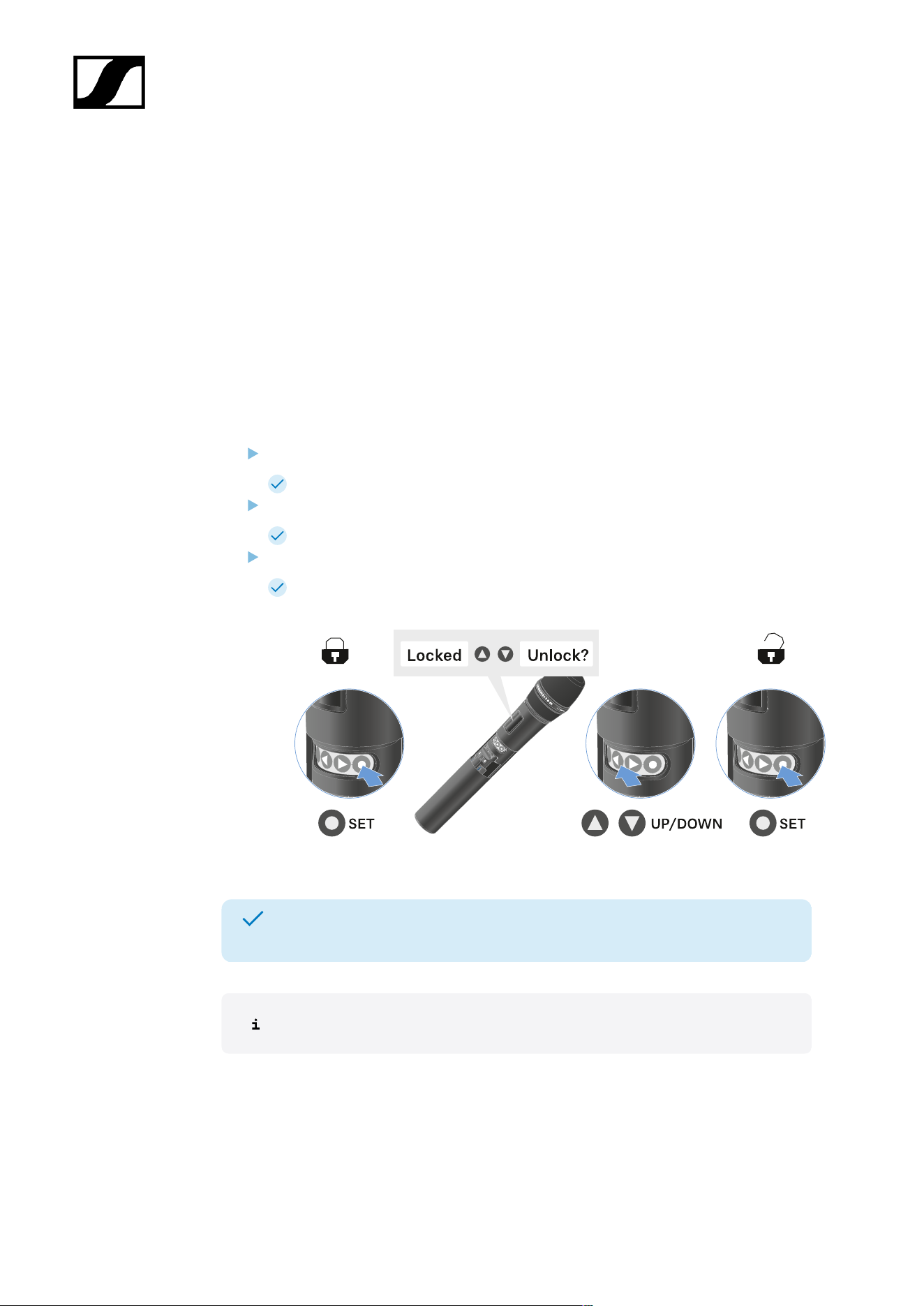
| 3 - Instruction manual
Lock-off function
You can enable or disable the automatic lock-off function in the Auto Lock menu item (see
Auto Lock menu item).
The lock-off function prevents the transmitter from being unintentionally switched off and
also prevents any unintentional changes to the transmitter’s configuration.
If you have enabled the Auto Lock function, you will have to temporarily deactivate the lock-
off function to operate the transmitter.
To temporarily deactivate the lock-off function:
Press the SET button.
Locked appears in the display panel.
Press the UP or DOWN button.
Unlock? appears in the display panel.
Press the SET button.
Lock-off function is now temporarily deactivated.
The lock-off function remains deactivated while you are actively working in the
operating menu.
After 10 seconds of inactivity, it automatically activates again.
389
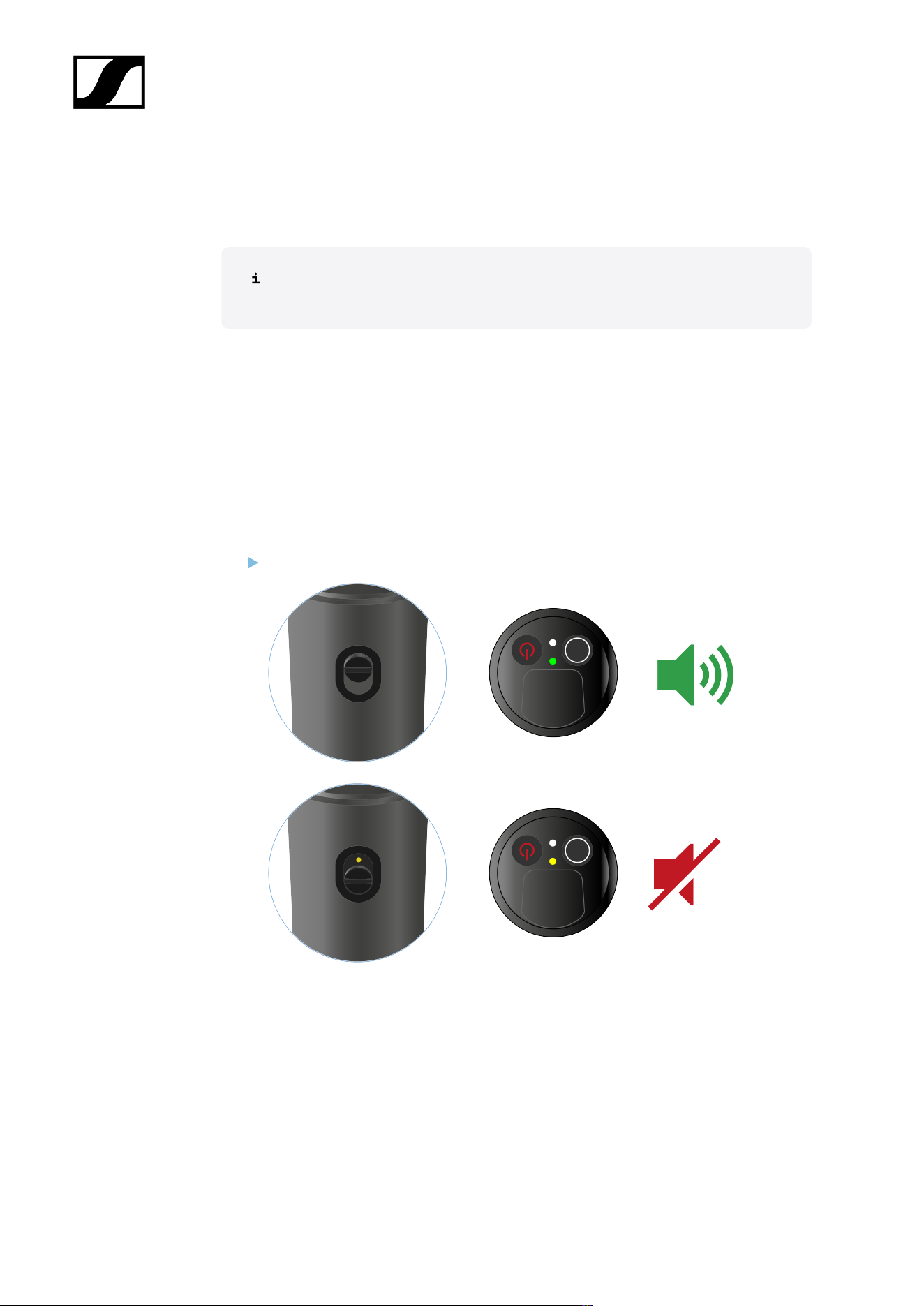
| 3 - Instruction manual
Configuring mute mode and muting the handheld transmitter
(EW-DX SKM-S only)
This function is only available for the EW-DX SKM-S version, not for the EW-DX
SKM version.
You can mute the handheld transmitter by using the mute switch to turn off either the audio
signal (AF Mute) or the RF signal (RF Mute).
To do this, you must configure the function of the mute switch in the Mute Mode menu item.
• On the receiver: Ch 1 / Ch 2 -> Mute Mode menu item
• On the transmitter: Mute Button menu item
AF Mute
Slide the mute switch to the desired position to mute or activate the audio signal.
390
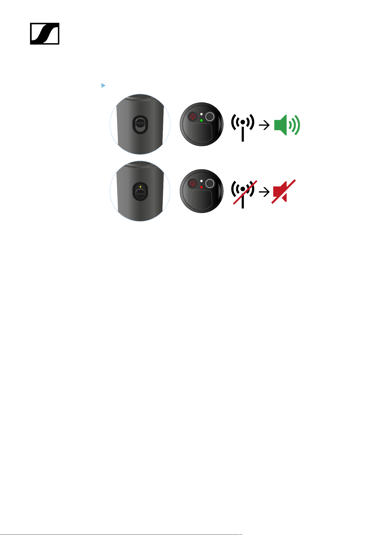
| 3 - Instruction manual
RF Mute
Slide the mute switch to the desired position to activate or deactivate the RF signal.
391

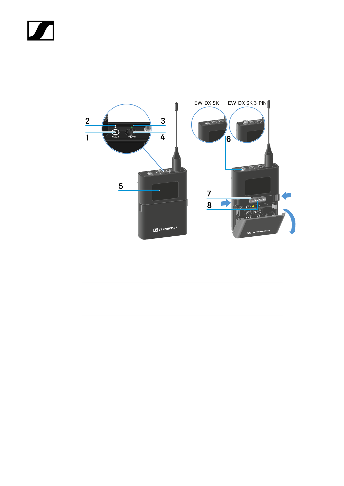
| 3 - Instruction manual
EW-DX SK | EW-DX SK 3-PIN bodypack transmitter
Product overview
1 SYNC button
• See Establishing a radio link | Synchronizing the receiver and transmitter
2 DATA LED
• See Meaning of the LEDs
3 LINK LED
• See Meaning of the LEDs
4 Mute switch
• See Configuring mute mode and muting the bodypack transmitter
5 Display panel
• See Information on the bodypack transmitter’s display
6 EW-DX SK: 3.5 mm jack socket
393

| 3 - Instruction manual
EW-DX SK 3-PIN: 3-pin socket
• See Connecting a microphone to the bodypack transmitter
• See Connecting an instrument or line source to the bodypack
transmitter
7 ON/OFF button
• See Switching the bodypack transmitter on and off
8 Function buttons for navigating the menu
• See Buttons for navigating the menu
394
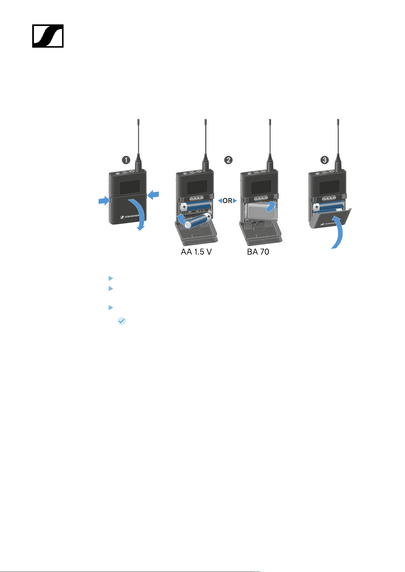
| 3 - Instruction manual
Inserting and removing the batteries/rechargeable batteries
You can operate the handheld transmitter either with batteries (AA, 1.5 V) or with the
rechargeable Sennheiser BA 70 battery.
Press the two catches and open the battery compartment cover.
Insert the batteries or the BA 70 rechargeable battery as indicated in the battery
compartment. Observe correct polarity.
Close the battery compartment.
The cover locks into place with an audible click.
395

| 3 - Instruction manual
Note about the BA 70 rechargeable battery
• Make sure that the BA 70 rechargeable battery is inserted as follows:
396
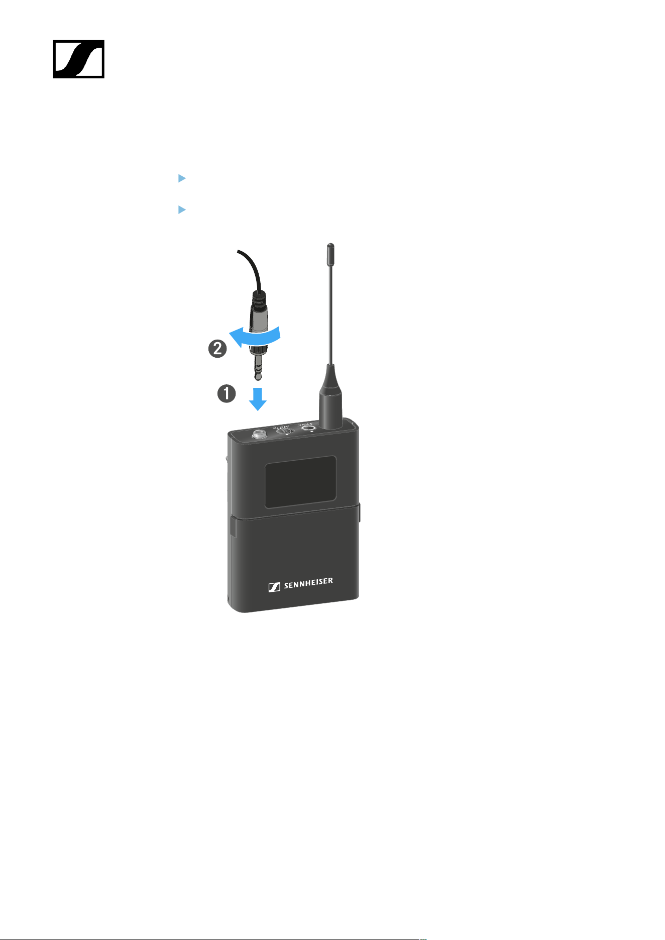
| 3 - Instruction manual
Connecting a microphone to the bodypack transmitter
To connect a microphone to the EW-DX SK bodypack transmitter:
Insert the cable’s 3.5 mm jack plug into the socket on the bodypack transmitter as
shown in the diagram.
Screw the plug’s coupling ring onto the audio socket thread of the bodypack
transmitter.
Compatible microphones
The following microphones are compatible with the EW-DX SK bodypack transmitter:
Lavalier microphones:
• ME 2 | Lavalier microphone with omni-directional pattern (models from 2021
and later with gold-plated plug*)
• ME 4 | Lavalier microphone with cardioid pattern (models from 2021 and later
with gold-plated plug*)
• MKE Essential Omni | Lavalier microphone with omni-directional pattern
• MKE 2 Gold | Lavalier microphone with omni-directional pattern (models from
2018 and later with blue serial number label)
397
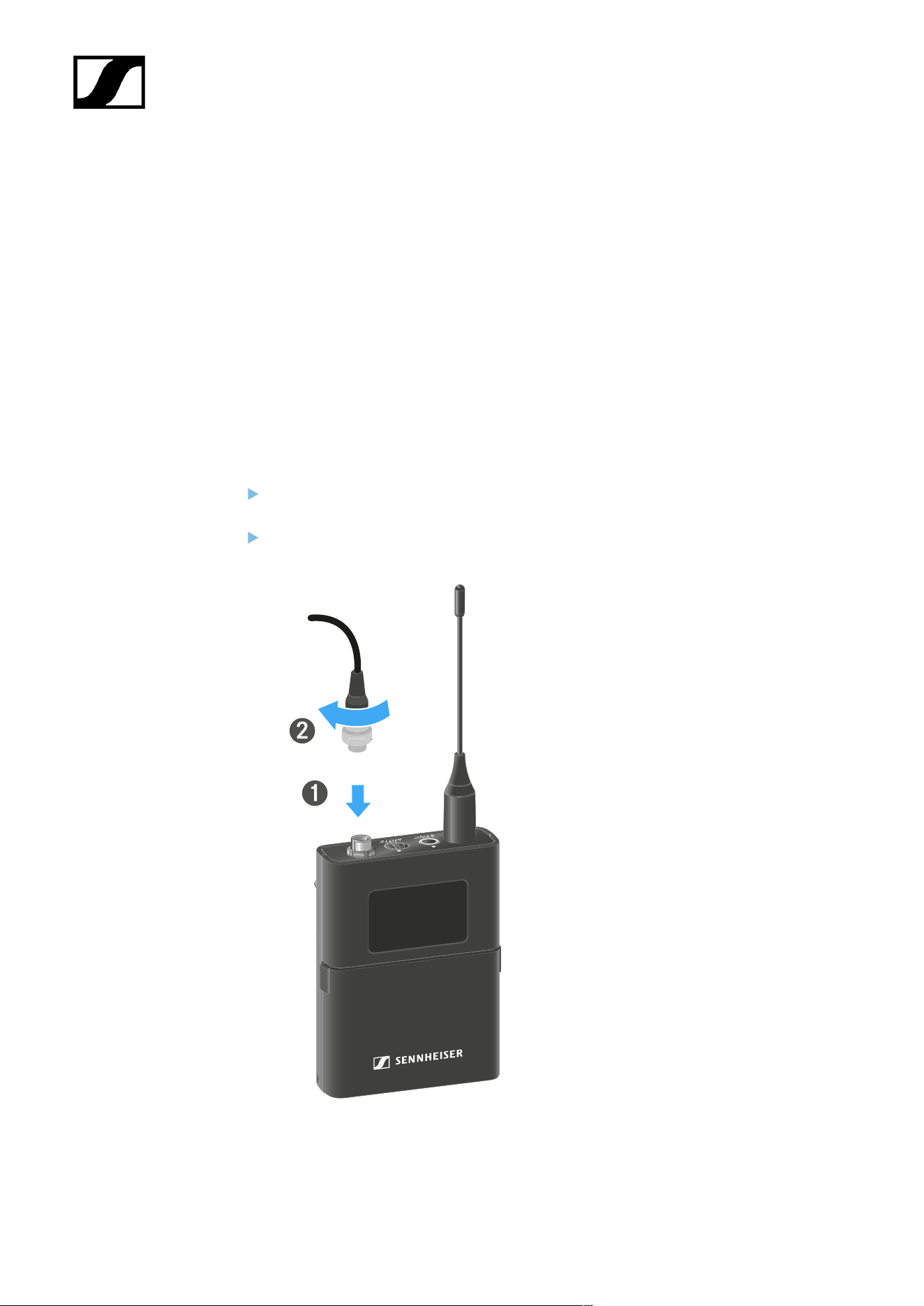
| 3 - Instruction manual
• MKE 1 | Lavalier microphone with omni-directional pattern
• MKE mini | Lavalier microphone with omni-directional pattern
• ME 3 | Headset microphone with cardioid pattern (models from 2021 and later
with gold-plated plug*)
• HSP Essential Omni | Headset microphone with omni-directional pattern
• HSP 2 | Headset microphone with omni-directional pattern (models from
March 2020 and later with code 1090 or higher)
• HS 2 | Headset microphone with omni-directional pattern (models from 2021
and later with gold-plated plug*)
• SL Headmic 1 | Headset microphone with omni-directional pattern
*Pre-2021 models with a nickel plug are not recommended. They can pick up noise if
they are placed too close to the transmitter.
To connect a microphone to the EW-DX SK 3-PIN bodypack transmitter:
Insert the cable’s three-pin plug into the socket on the bodypack transmitter as shown
in the diagram.
Screw the plug’s coupling ring onto the audio socket thread of the bodypack
transmitter.
Compatible microphones
398

| 3 - Instruction manual
The following microphones are compatible with the EW-DX SK 3-PIN bodypack
transmitter:
Lavalier microphones:
• MKE 1-4 | Lavalier microphone with omni-directional pattern
• MKE 2-4 | Lavalier microphone with omni-directional pattern
• MKE 40-4 | Lavalier microphone with cardioid pattern
• MKE Essential Omni Black-3-Pin | Lavalier microphone with omni-directional
pattern
• MKE Essential Omni Beige-3-Pin | Lavalier microphone with omni-directional
pattern
Headset microphones:
• HSP Essential Omni Black-3-Pin | Headset microphone with omni-directional
pattern
• HSP Essential Omni Beige-3-Pin | Headset microphone with omni-directional
pattern
• HSP 2 | Headset microphone with omni-directional pattern
• HSP 4 | Headset microphone with cardioid pattern
• SL Headmic 1-4 | Headset microphone with omni-directional pattern
399
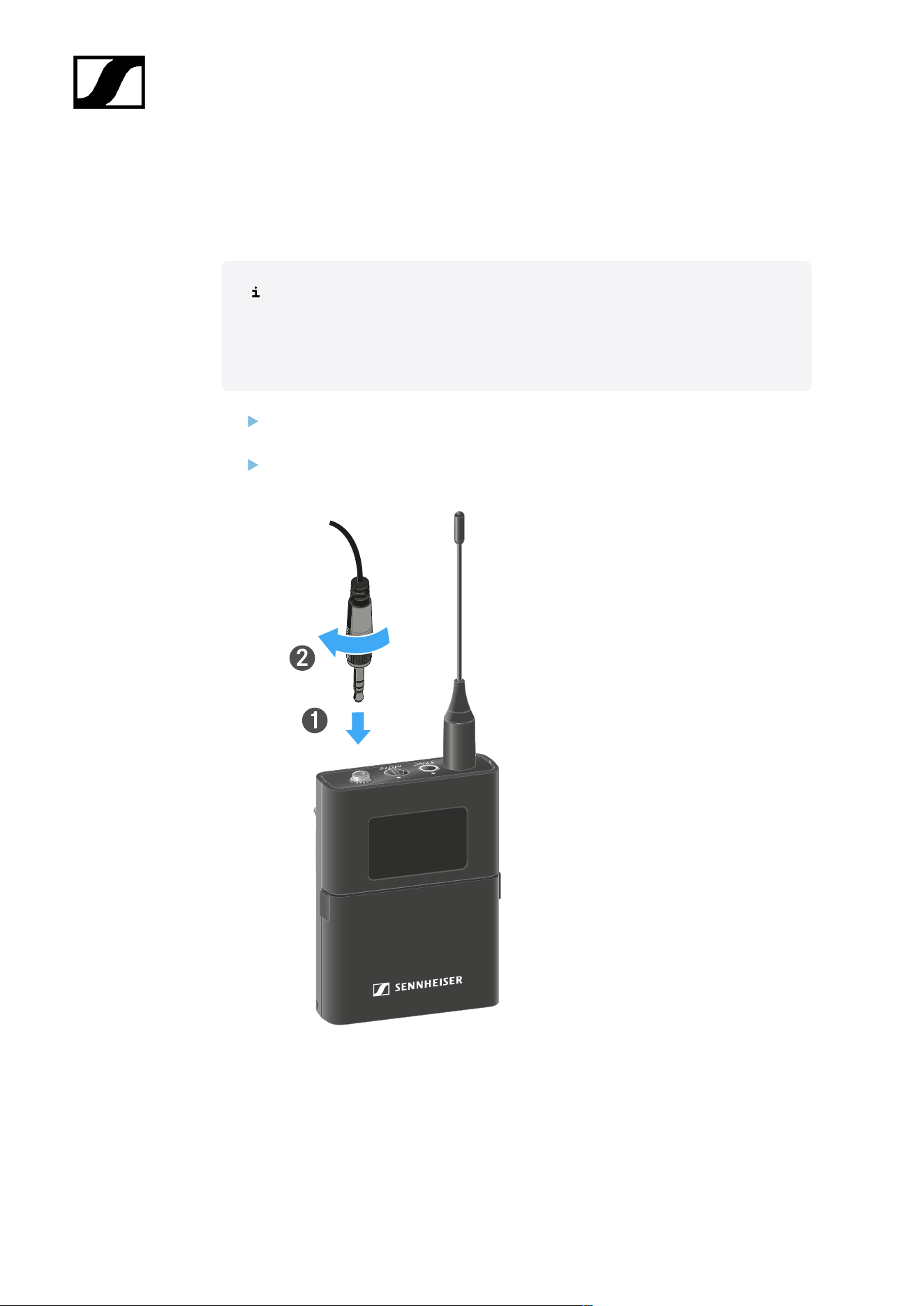
| 3 - Instruction manual
Connecting an instrument or line source to the bodypack
transmitter
To connect a microphone to the EW-DX SK 3-PIN bodypack transmitter:
You can connect instruments or audio sources with a line level to the bodypack
transmitter.
To do this, you will need the CL 1 (6.3 mm jack plug on a lockable 3.5 mm jack
plug) or CL 2 (XLR-3F plug on a lockable 3.5 mm jack plug) Sennheiser cables.
Insert the cable’s 3.5 mm jack plug into the socket on the bodypack transmitter as
shown in the diagram.
Screw the plug’s coupling ring onto the audio socket thread of the bodypack
transmitter.
400
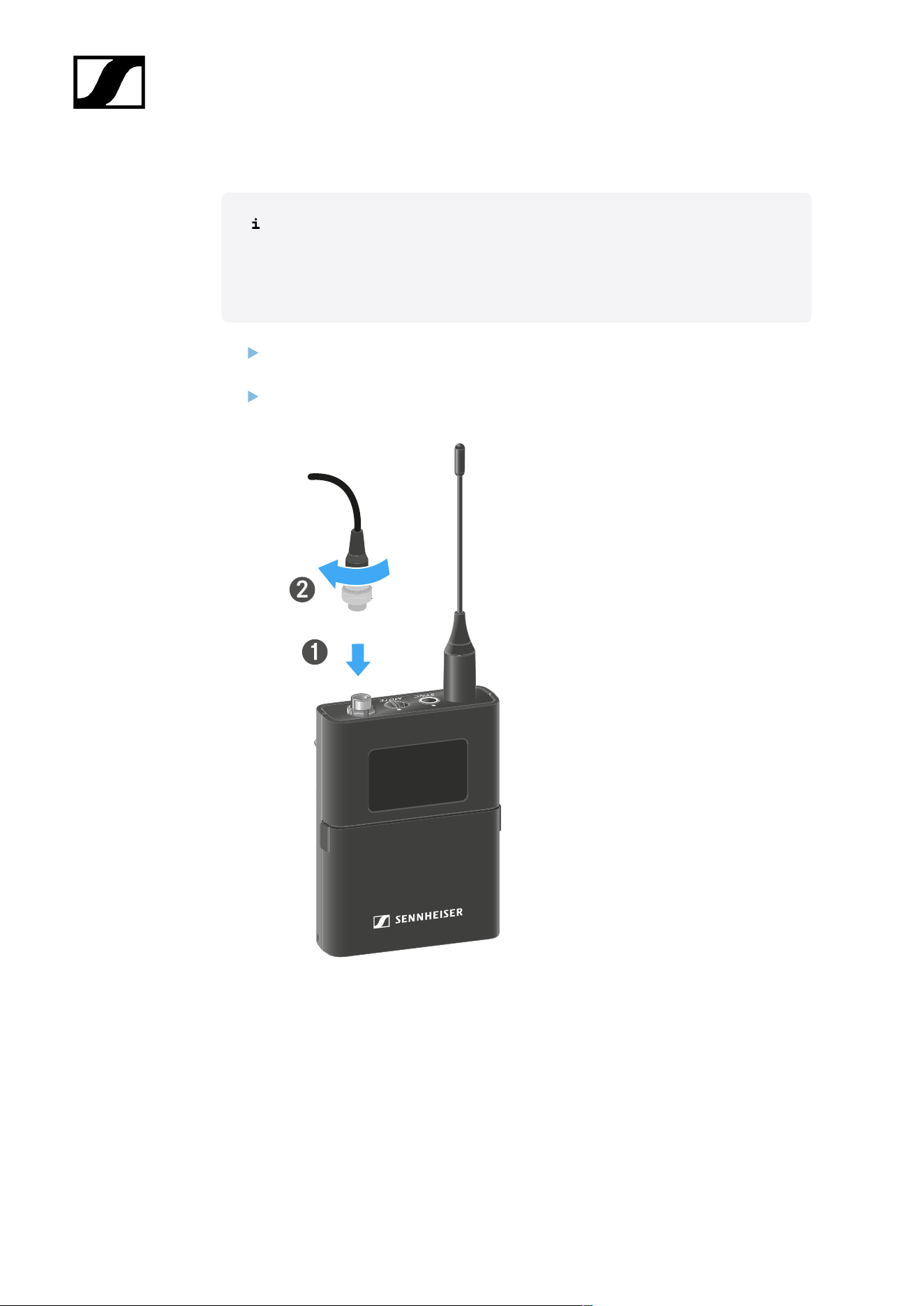
| 3 - Instruction manual
To connect an instrument or line source to bodypack transmitter:
You can connect instruments or audio sources with a line level to the bodypack
transmitter.
To do so, you require the Sennheiser CI 1-4 cable (6.3 mm (1/4") jack plug to
screw-on 3-pin audio connector).
Insert the cable’s three-pin plug into the socket on the bodypack transmitter as shown
in the diagram.
Screw the plug’s coupling ring onto the audio socket thread of the bodypack
transmitter.
401

| 3 - Instruction manual
Changing the belt clip
You can change the belt clip on the bodypack transmitter or flip it over depending on how
you want to wear it.
To remove the belt clip:
Carefully loosen the belt clip with a small screwdriver as shown in the figure.
Be very careful not to scratch the housing.
To insert the belt clip:
Insert one side of the belt clip first as shown in the figure.
Then insert the second side of the belt clip.
Gently press the belt clip all the way in on both sides.
Always insert one side before the other, not at the same time, as otherwise the belt
clip could bend.
402
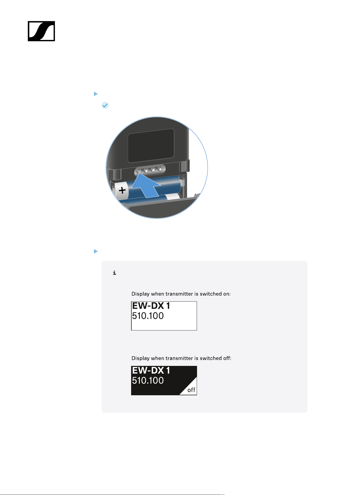
| 3 - Instruction manual
Switching the bodypack transmitter on and off
To switch the bodypack transmitter on:
Short-press the ON/OFF button.
The LINK LED lights up and the transmitter switches on.
To switch the bodypack transmitter off:
Hold down the ON/OFF button until the LEDs switch off.
Note that the transmitter’s permanent E-Ink display still displays the
parameters after it is switched off.
403
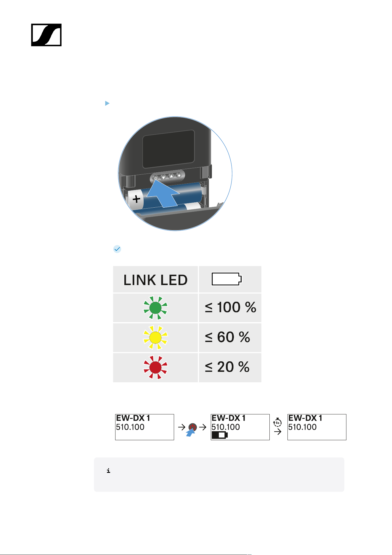
| 3 - Instruction manual
Checking the battery status of the transmitter (Check function)
To check the battery status of the transmitter:
Short-press the ON/OFF button on the transmitter.
The transmitter’s LINK LED flashes to indicate the current charge level of the
battery or the BA 70 rechargeable battery.
In addition, the battery status is displayed on the transmitter display for approx. 5
seconds.
Pressing the transmitter’s ON/OFF button will simultaneously trigger the Identify
function: Identifying the paired receiver (Identify function).
404
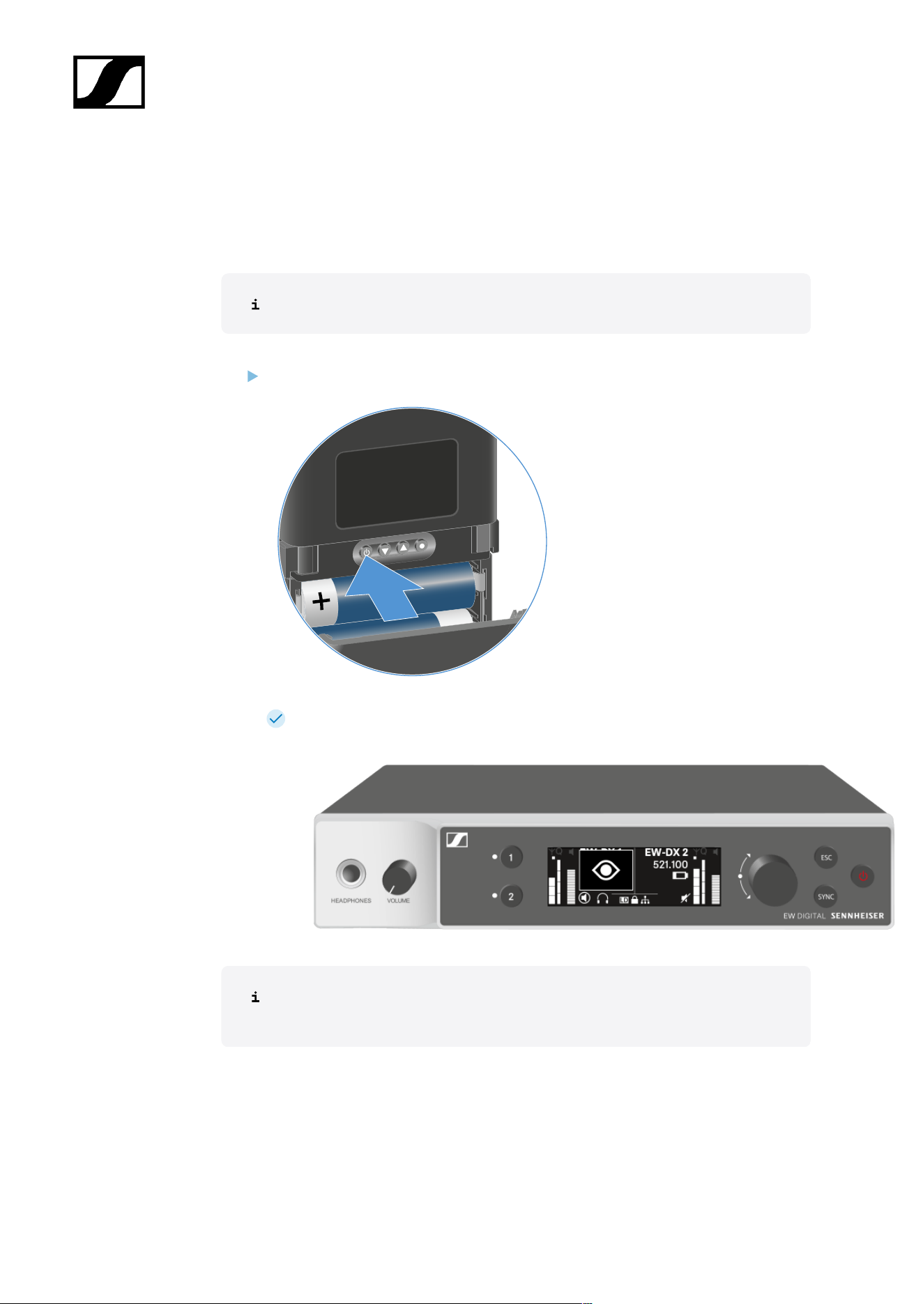
| 3 - Instruction manual
Identifying the paired receiver (Identify function)
In multi-channel systems, you can use the Check function to quickly identify to which
receiver the transmitter is paired.
Both the transmitter and receiver must be switched on.
Short-press the ON/OFF button on the transmitter.
An eye flashes next to the respective receiving channel on the coupled receiver’s
display.
Pressing the transmitter’s ON/OFF button will simultaneously trigger the Check
function: Checking the battery status of the transmitter (Check function).
405

| 3 - Instruction manual
Meaning of the LEDs
The LINK and DATA LEDs on the top of the transmitter can indicate the following information.
LINK LED
The LINK LED provides information about the status of the radio link between the transmitter
and receiver, as well as status information for the paired transmitter.
The LED is green:
• The link between the transmitter and receiver is
established.
• The transmission frequency is active.
The LED is yellow:
• The link between the transmitter and receiver is
established.
• The audio signal is muted.
Or
• No microphone module is mounted on the SKM-S
handheld transmitter.
The LED is flashing yellow:
• The link between the transmitter and receiver is
established.
• The audio signal is overdriven (clipping).
406

| 3 - Instruction manual
The LED is continuously red:
• The (rechargeable) battery in the transmitter is
dead.
The LED is flashing red:
• The link between the transmitter and receiver is
established.
• The battery/rechargeable battery in the
transmitter is low.
The LED is off:
• No link between the transmitter and receiver.
• The transmitter is switched off.
DATA LED
The DATA LED provides information about the synchronization of transmitters and receivers.
The LED is flashing blue:
• The transmitter is being synchronized with a receiver.
The LED is blue:
• The firmware is being updated.
407

| 3 - Instruction manual
The LED is off:
• There is currently no active data link.
408

| 3 - Instruction manual
Establishing a connection to the receiver
To establish a radio link between the transmitter and the receiver, the devices must be
synchronized.
See Establishing a radio link | Synchronizing the receiver and transmitter
Conditions and restrictions for using frequencies
There may be special conditions and restrictions for using frequencies in your
country.
Before putting the product into operation, find the information for your country
at the following address:
sennheiser.com/sifa
409
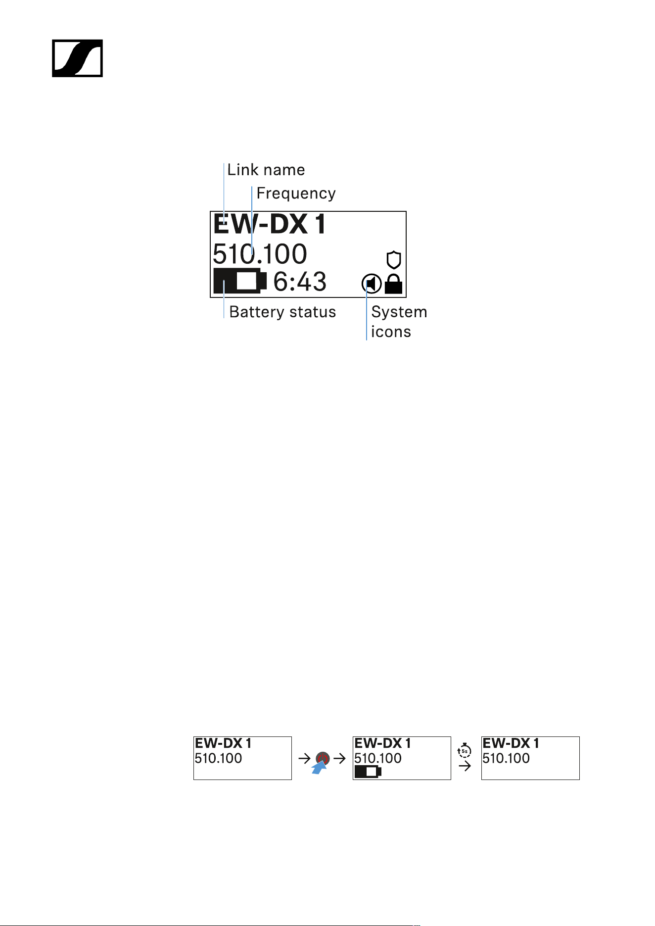
| 3 - Instruction manual
Information on the bodypack transmitter’s display
You can view the following information on the transmitter display.
Link name
• You can assign a name to the radio link in the transmitter’s menu (see Name menu
item).
• Alternatively, you can assign the name in the receiver’s menu and then synchronize it
to the transmitter (see Ch 1 / Ch 2 -> Name menu item).
Frequency
• You can manually set the frequency of the radio link in the transmitter’s menu (see
Frequency menu item).
• The frequency of the radio link can also be set manually in the receiver’s menu (see
Ch 1 / Ch 2 -> Frequency menu item) or via the Auto Setup function (see Ch 1 / Ch 2
-> Scan / Auto Setup menu item) and then synchronized to the transmitter.
Battery status
• Displays the charging status of the batteries or the BA 70 battery pack.
• When using the BA 70 rechargeable battery, the remaining runtime is also displayed
in hours and minutes.
• The battery status is hidden in the display’s default state. Short-press the On/Off
button on the transmitter (Check function, see Checking the battery status of the
transmitter (Check function)) to display the battery status for approx. 5 seconds.
410
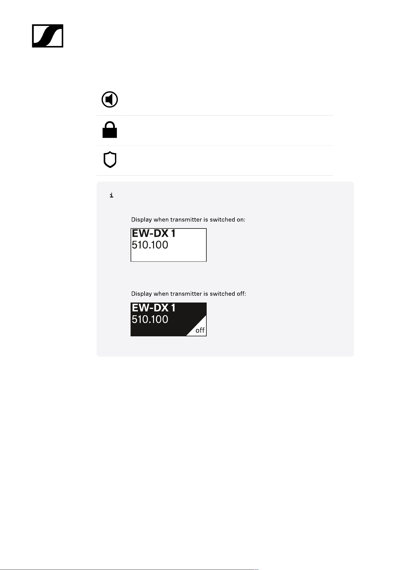
| 3 - Instruction manual
System icons
The transmitter’s mute switch is deactivated. See Mute Button menu item.
The Auto Lock function is activated. See Auto Lock menu item.
AES 256 encryption is enabled. See System -> Link Encryption menu
item.
Note that the transmitter’s permanent E-Ink display still displays the parameters
after it is switched off.
411
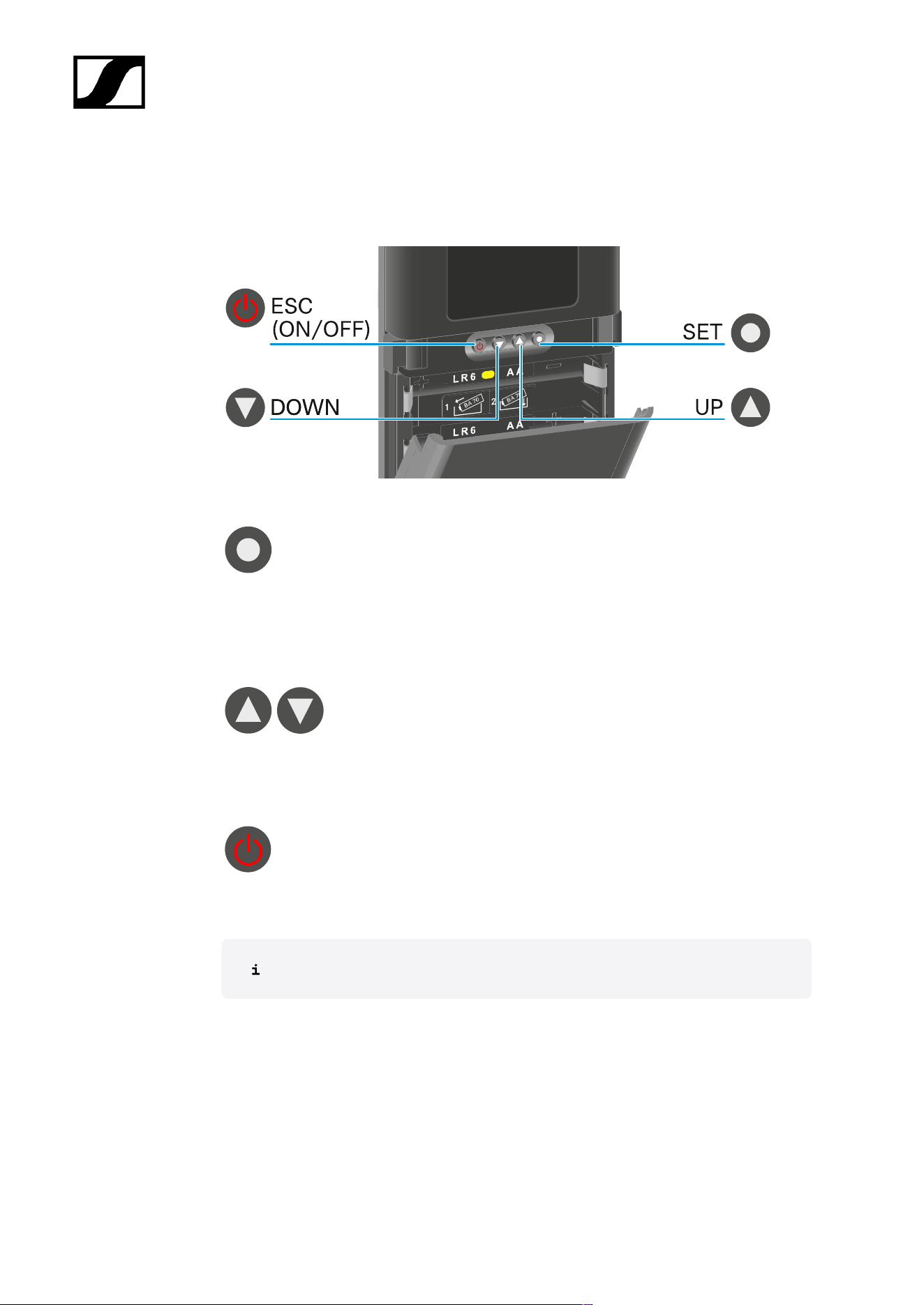
| 3 - Instruction manual
Buttons for navigating the menu
Use the following buttons to navigate through the transmitter’s operating menu.
Press the SET button
• Jumps from the home screen to the operating menu
• Calls up a menu item
• Saves settings
Press the UP or DOWN button
• Changes to the previous or next menu item
• Changes the setting of a menu item
Press the ESC (ON/OFF) button
• Cancels the entry and returns to the previous display
Opening the menu and navigating the menu items
412

| 3 - Instruction manual
Opening the menu and navigating the menu items
Navigating through the menu and making changes in a menu item
To open the menu:
Press the SET button.
The operating menu is shown on the transmitter display panel.
To open a menu item:
Press the UP or DOWN buttons to navigate through the individual menu items.
Press the SET button to open the selected menu item.
To make changes in a menu item:
Press the UP or DOWN buttons to set the displayed value.
Press the SET button to save the setting.
Press the ESC button to leave the menu item without saving the setting.
Name menu item
You can enter the name of the link in this menu item.
Press the UP or DOWN buttons to select a character.
Press the SET button to go to the next position.
413

| 3 - Instruction manual
At the last position, press the SET button to save the selected name.
If you enter a name for the radio link in the Name menu item on the
receiver and then synchronize the receiving channel with the transmitter,
the name entered in the transmitter is overwritten with the name entered
in the receiver.
414

| 3 - Instruction manual
Frequency menu item
In this menu item, you can set the transmitter’s transmission frequency.
Press the UP or DOWN button to set the frequency’s MHz range.
Press the SET button to confirm your selection.
Press the UP or DOWN button to set the frequency’s kHz range.
Press the SET button to save the set frequency.
If you set a frequency for the channel using the Frequency menu item on
the receiver or via the Scan / Auto Setup function and then synchronize
the receiving channel with the transmitter, the frequency entered in the
transmitter is overwritten by the frequency set in the receiver.
415

| 3 - Instruction manual
Low Cut menu item
In this menu item, you can adjust the value for the low cut filter.
• Setting range: Off, 30 Hz, 60 Hz, 80 Hz, 100 Hz, 120 Hz
Press the UP or DOWN button to set the desired value.
Press the SET button to confirm your selection.
If you set a value for the channel’s low cut filter using the Low Cut menu
item on the receiver and then synchronize the receiving channel with
the transmitter, the value entered in the transmitter is overwritten by the
value set in the receiver.
416

| 3 - Instruction manual
Trim menu item
In this menu item, you can adjust the audio level of the transmitter as well as the gain of the
wireless link (can be set only on the receiver) to suit input signals of different volumes.
• Setting range: -12 dB to +6 dB in increments of 1 dB
Press the UP or DOWN button to set the desired value.
Press the SET button to confirm your selection.
If you set a value for the channel in the Trim menu item on the receiver
and then synchronize the receiving channel with the transmitter, the value
entered in the transmitter is overwritten with the value entered in the
receiver.
417
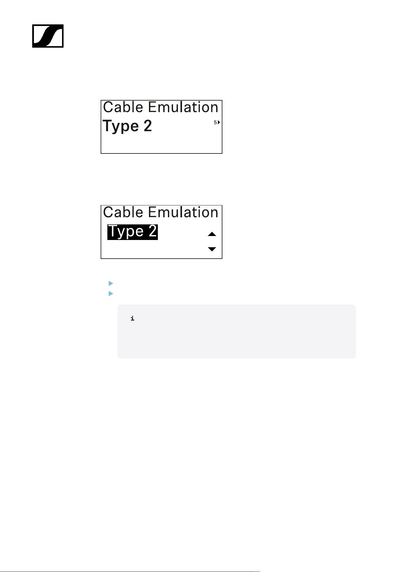
| 3 - Instruction manual
Cable Emulation menu item
In this menu item, you can emulate instrument cable lengths
• Setting range: Off, Type 1, Type 2, Type 3
Press the UP or DOWN button to set the desired value.
Press the SET button to confirm your selection.
If you set a value for the channel in the Cable Emul. menu item on the
receiver and then synchronize the receiving channel with the transmitter,
the value entered in the transmitter is overwritten with the value entered
in the receiver.
418

| 3 - Instruction manual
Test Tone menu item
In this menu item, you can activate a test tone that the transmitter transmits instead of the
input signal. You can use this feature to level out the system, for example.
• Setting range: Off, -90 dB to 0 dB in 6 dB increments
Press the UP or DOWN button to set the desired value.
Press the SET button to confirm your selection.
419
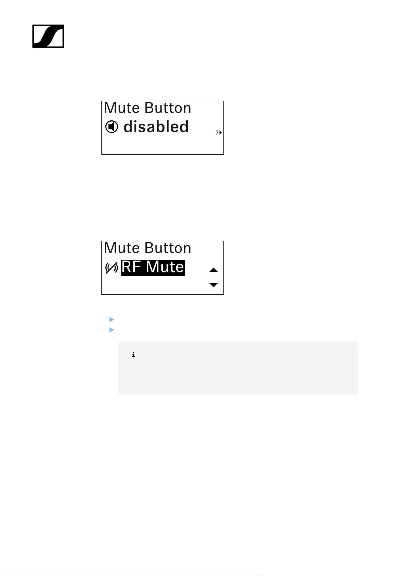
| 3 - Instruction manual
Mute Button menu item
In this menu item you can set the function of the transmitter’s mute switch.
Setting range:
• Disabled: The mute switch has no function.
• RF Mute: The RF signal is deactivated when the mute switch is on.
• AF Mute: The audio signal is muted when the mute switch is on.
Press the UP or DOWN button to set the desired value.
Press the SET button to confirm your selection.
If you set a function for the transmitter’s mute switch in the Mute Mode
menu item on the receiver and then synchronize the receiving channel
with the transmitter, the value entered in the transmitter is overwritten
with the value entered in the receiver.
420

| 3 - Instruction manual
Auto Lock menu item
In this menu item, you can activate or deactivate the automatic lock-off for the transmitter.
The lock-off prevents the transmitter from being unintentionally switched off and also
prevents any changes to the transmitter’s menu.
The lock-off prevents the transmitter from being unintentionally switched off and
also prevents any changes to the transmitter’s menu. See Lock-off function.
Press the UP or DOWN button to set the desired value.
Press the SET button to confirm your selection.
If you set a value for the transmitter’s automatic lock-off in the Auto Lock
menu item on the receiver and then synchronize the receiving channel
with the transmitter, the value entered in the transmitter is overwritten
with the value entered in the receiver.
421

| 3 - Instruction manual
Brightness menu item
In this menu item, you can adjust the brightness of the transmitter’s display.
You can turn off the backlight completely or set it to one of five brightness levels.
Press the UP or DOWN button to set the desired value.
Press the SET button to confirm your selection.
422

| 3 - Instruction manual
LED menu item
This menu item allows you to set the behavior of the transmitter’s LINK LED.
Setting range:
• ON: The LINK LED remains continuously lit.
• OFF: The LINK LED switches off while the lock-off function is active.
Press the UP or DOWN button to set the desired value.
Press the SET button to confirm your selection.
If you set a function for the transmitter’s LINK LED in the LED menu
item on the receiver and then synchronize the receiving channel with the
transmitter, the value entered in the transmitter is overwritten with the
value entered in the receiver.
423
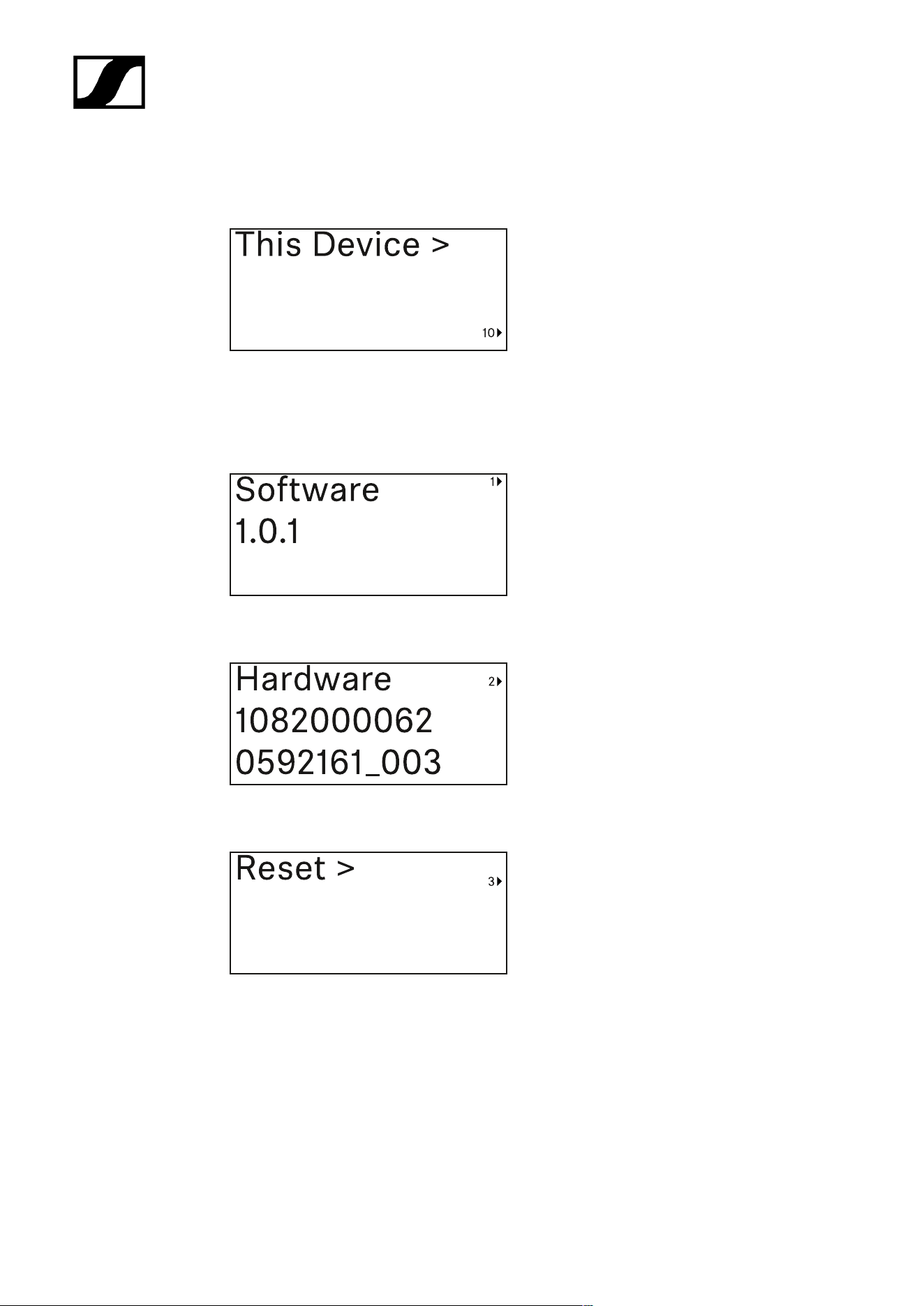
| 3 - Instruction manual
This Device menu item
In this menu item you can view information about the transmitter’s software and hardware
and reset the transmitter to the factory settings.
Show software
Shore hardware
Reset to factory settings
424
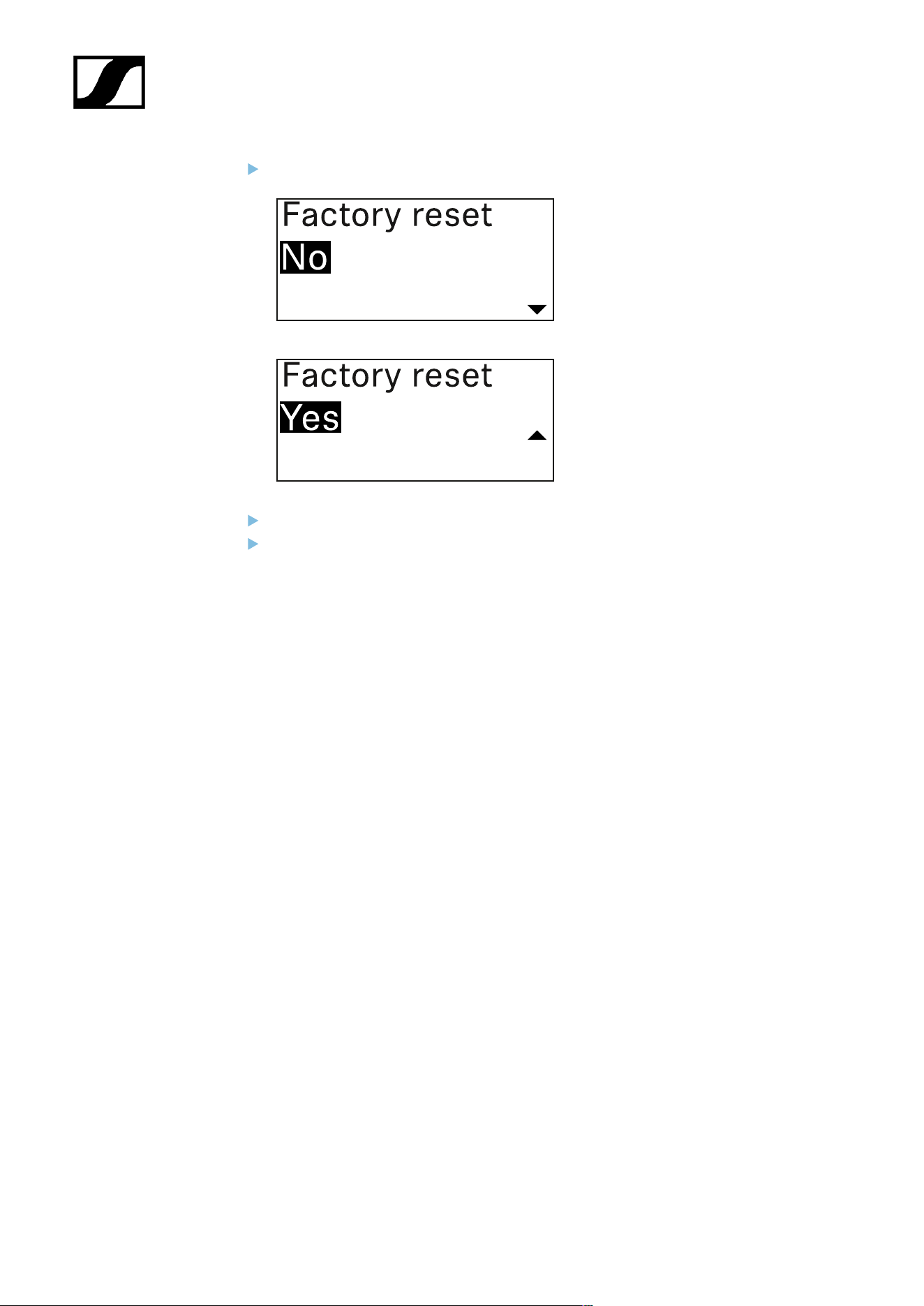
| 3 - Instruction manual
Press the SET button to open the Reset menu item.
Press the UP or DOWN button to set the desired value.
Press the SET button to confirm your selection.
425
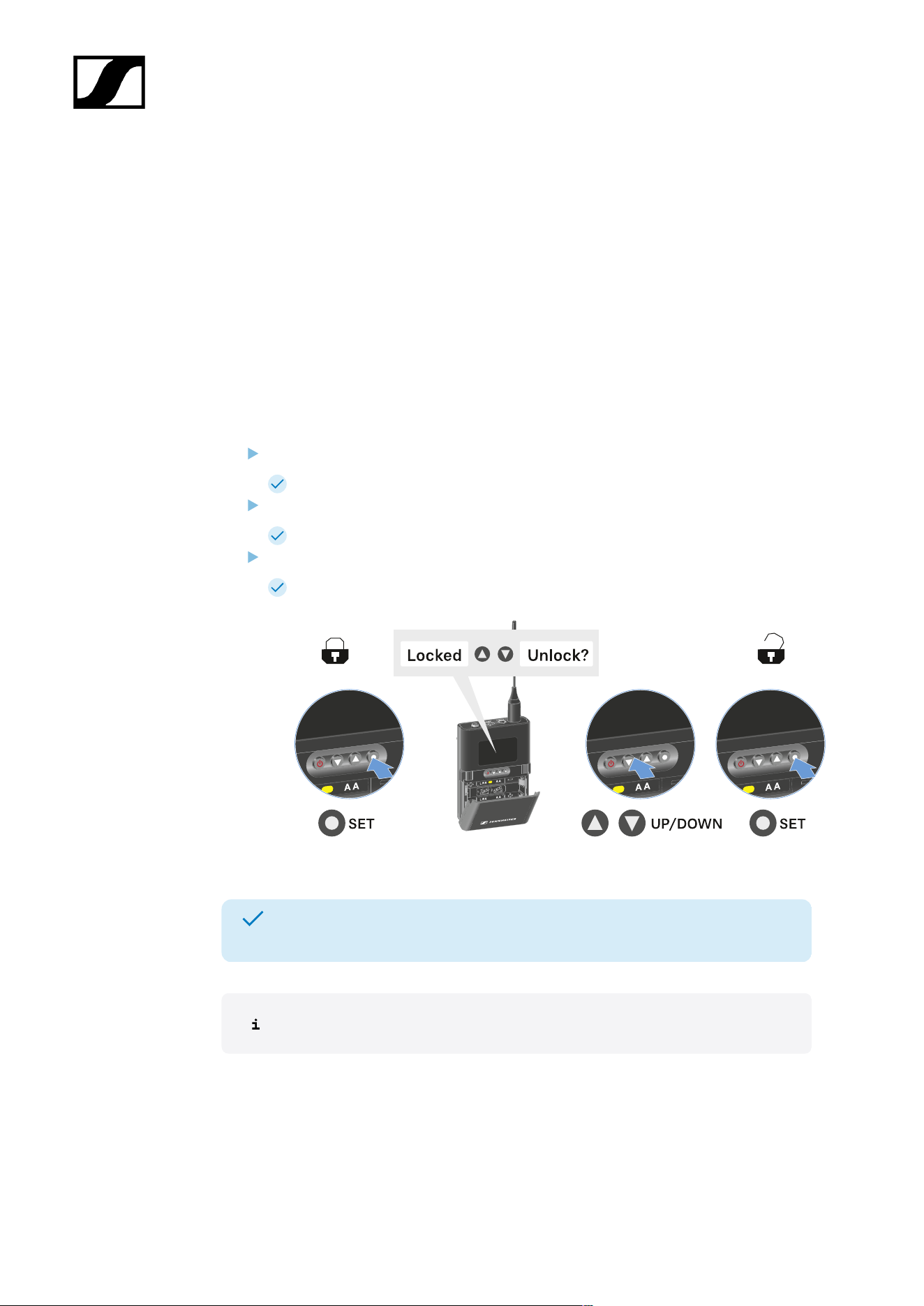
| 3 - Instruction manual
Lock-off function
You can enable or disable the automatic lock-off function in the Auto Lock menu item (see
Auto Lock menu item).
The lock-off function prevents the transmitter from being unintentionally switched off and
also prevents any unintentional changes to the transmitter’s configuration.
If you have enabled the Auto Lock function, you will have to temporarily deactivate the lock-
off function to operate the transmitter.
To temporarily deactivate the lock-off function:
Press the SET button.
Locked appears in the display panel.
Press the UP or DOWN button.
Unlock? appears in the display panel.
Press the SET button.
Lock-off function is now temporarily deactivated.
The lock-off function remains deactivated while you are actively working in the
operating menu.
After 10 seconds of inactivity, it automatically activates again.
426
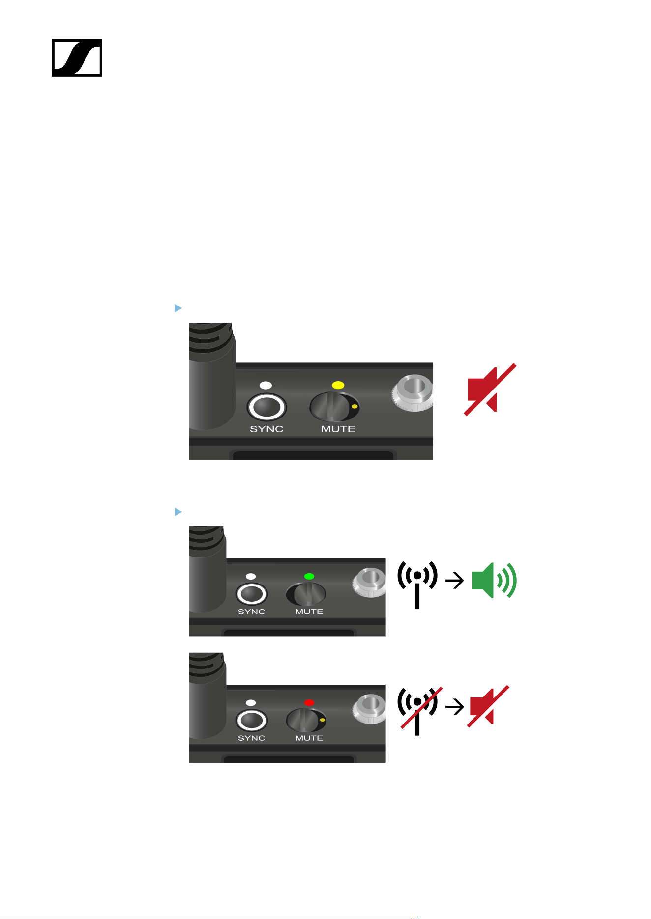
| 3 - Instruction manual
Configuring mute mode and muting the bodypack transmitter
You can mute the handheld transmitter by using the mute switch to turn off either the audio
signal (AF Mute) or the RF signal (RF Mute).
To do this, you must configure the function of the mute switch in the Mute Mode menu item.
• On the receiver: Ch 1 / Ch 2 -> Mute Mode menu item
• On the transmitter: Mute Button menu item
AF Mute
Slide the mute switch to the desired position to mute or activate the audio signal.
RF Mute
Slide the mute switch to the desired position to activate or deactivate the RF signal.
427

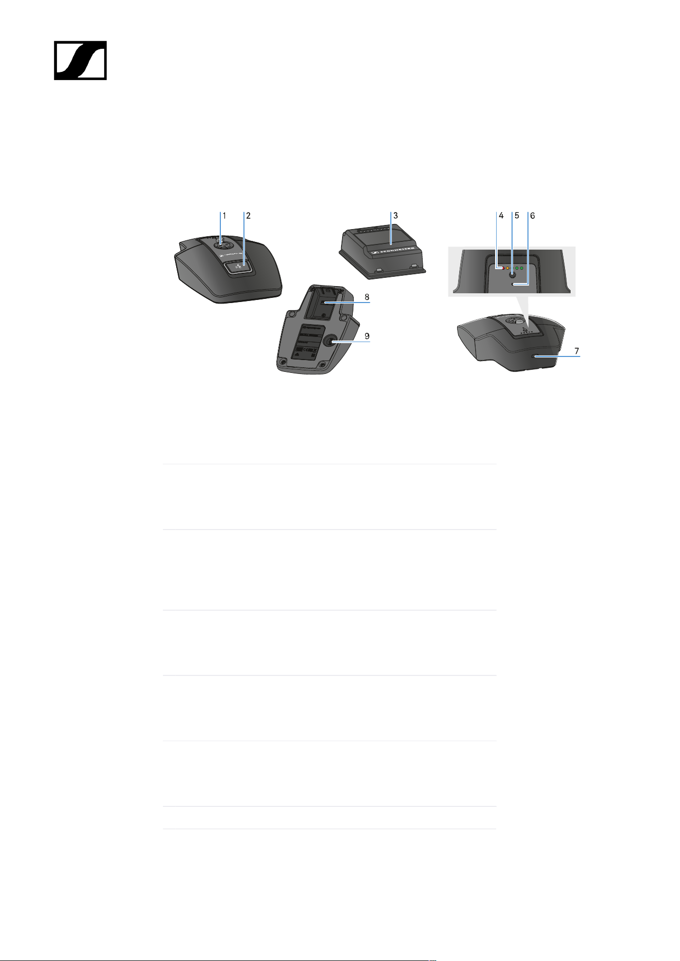
| 3 - Instruction manual
Table stand EW-DX TS 3-pin | EW-DX TS 5-pin
Product overview
1 XLR socket for connecting a gooseneck microphone
• See Connecting a gooseneck microphone
2 MUTE button with LED
• See Muting the table stand
3 BA 40 rechargeable battery
• See Inserting and removing the BA 40 rechargeable
battery
4 Charge level LEDs
• See Meaning of the LEDs
5 ON/OFF button with charge level display
• See Switching the table stand on/off
6 Bluetooth LED
• See Meaning of the LEDs
7 USB-C socket
429

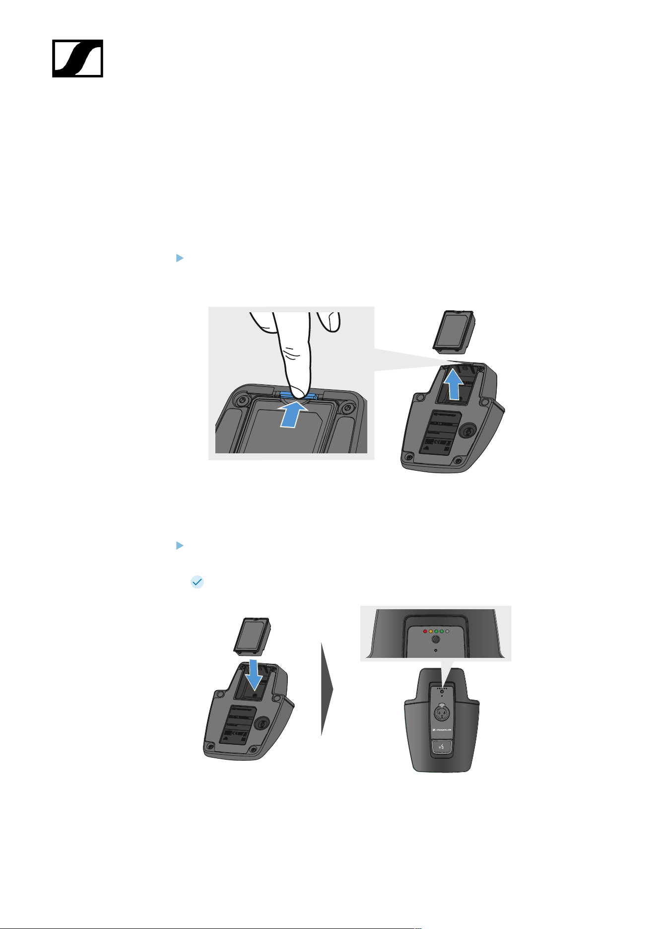
| 3 - Instruction manual
Inserting and removing the BA 40 rechargeable battery
The included BA 40 rechargeable battery is used to power the table stand. The battery must
be charged before first use, either with the optional CHG 2W charging base or in the table
stand with a USB cable.
To remove the battery:
Pull the unlock button away from the battery and pull the battery out of the
compartment.
To insert the battery:
Slide the battery into the compartment with the correct orientation until the unlock
button locks into place.
The charge level LEDs light up briefly and indicate the charge level.
431
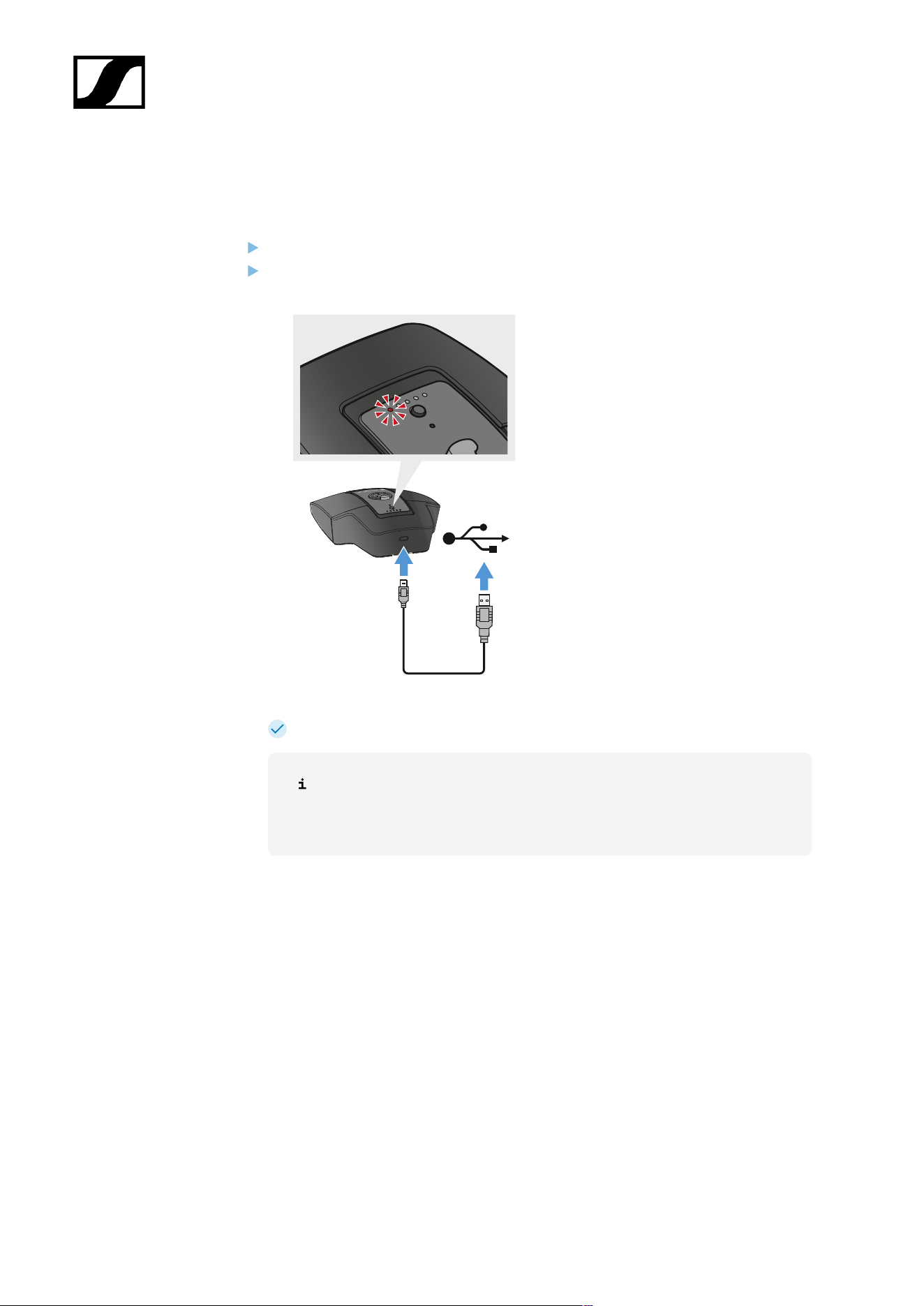
| 3 - Instruction manual
Charging the table stand
To charge the table stand via USB:
Connect the USB cable’s USB-C plug to the USB-C socket of the table stand.
Plug the other end of the USB cable into a USB power supply unit.
The charge level LEDs indicate the charge level.
Time until fully charged:
• EW-DX TS 3-pin: 7 hours when on, 5.5 hours when off
• EW-DX TS 5-pin: 7.5 hours when on, 5.5 hours when off
432
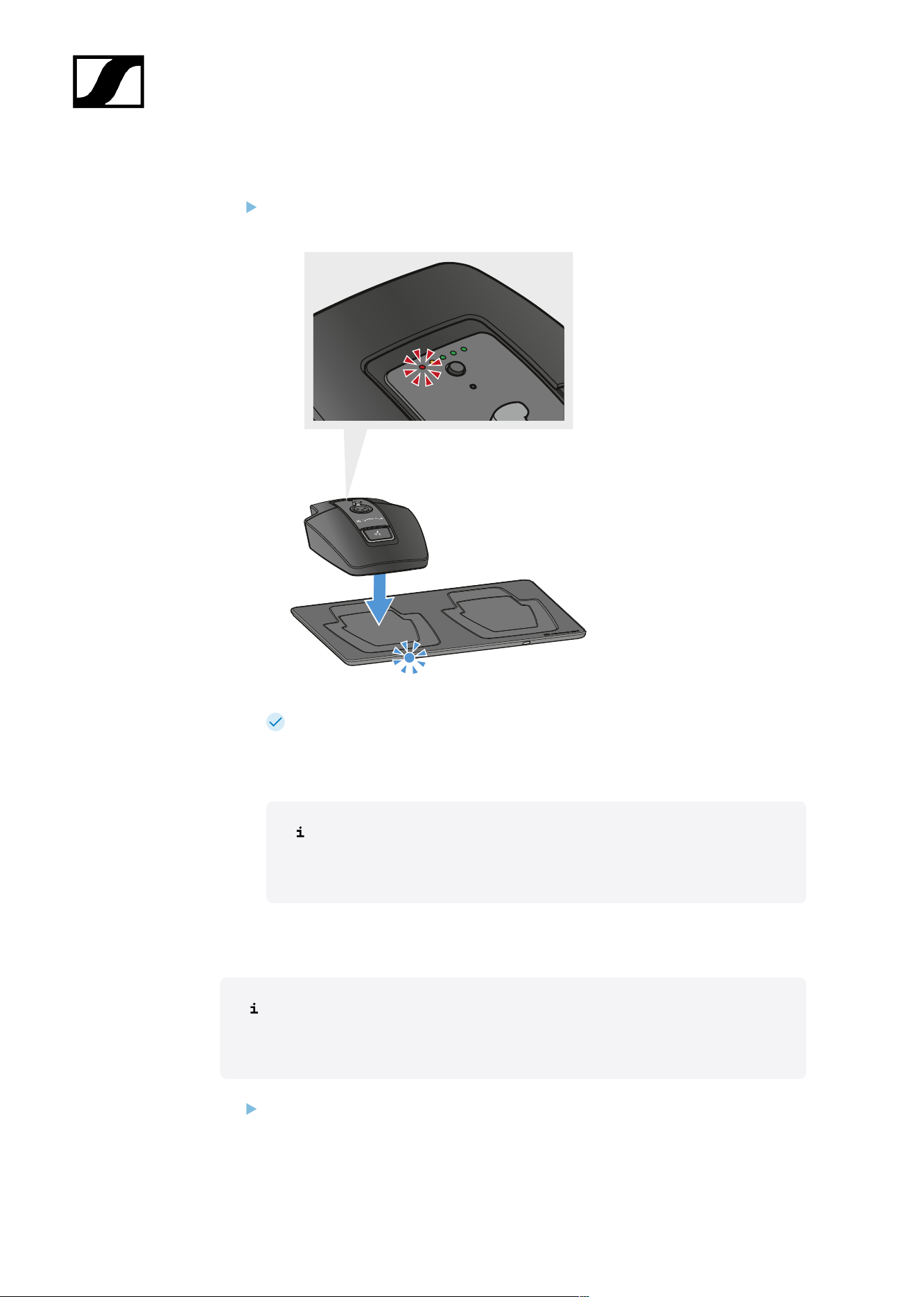
| 3 - Instruction manual
To charge the table stand using the wireless CHG 2W charging base:
Place the table stand on marked area of the CHG 2W charging base.
When the table stand is positioned correctly on the charging surface, the charge
level LEDs indicate the charge level.
The LEDs on the CHG 2W charging base flash blue during charging.
Time until fully charged:
• EW-DX TS 3-pin: 5 hours when on, 4.5 hours when off
• EW-DX TS 5-pin: 5.5 hours when on, 4.5 hours when off
To charge the table stand with a wireless Qi charging base from a third-party
manufacturer:
You can charge the table stand with any charging base that uses the wireless
Qi charging standard. Place the table stand on the third-party Qi charging base.
The charge level LED lights up once the table stand is correctly positioned.
You can find more information about third-party Qi charging bases in the
documentation from the respective manufacturers.
433
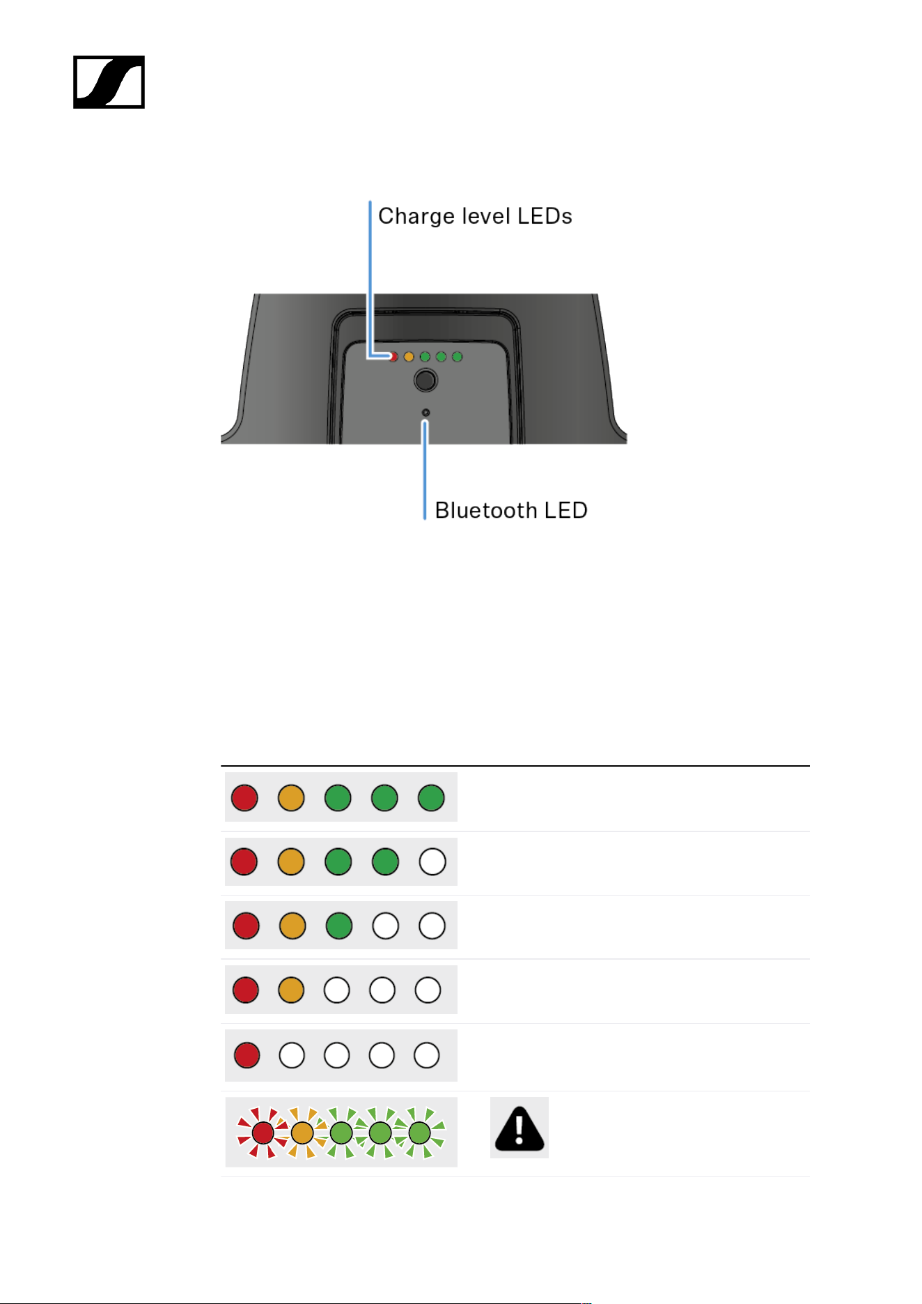
| 3 - Instruction manual
Meaning of the LEDs
The charge level and Bluetooth LEDs on the top of the transmitter can indicate the following
information.
Charge level LEDs
The charge level is indicated on the table stand via the charge level LEDs. At 100% charge,
the EW-DX TS 3-pin and EW-DX TS 5-pin have an approximate operating time of 11 and 10
hours respectively.
The operating time with the BA 40 rechargeable battery is as follows:
100 %
80 %
60 %
40 %
20 %
Low battery
434
| 3 - Instruction manual
Bluetooth LED
The Bluetooth LED provides information about the synchronization of transmitters and
receivers.
The LED is flashing blue:
• The transmitter is being synchronized with a
receiver.
The LED is blue:
• The firmware is being updated.
The LED is off:
• There is currently no active data link.
435
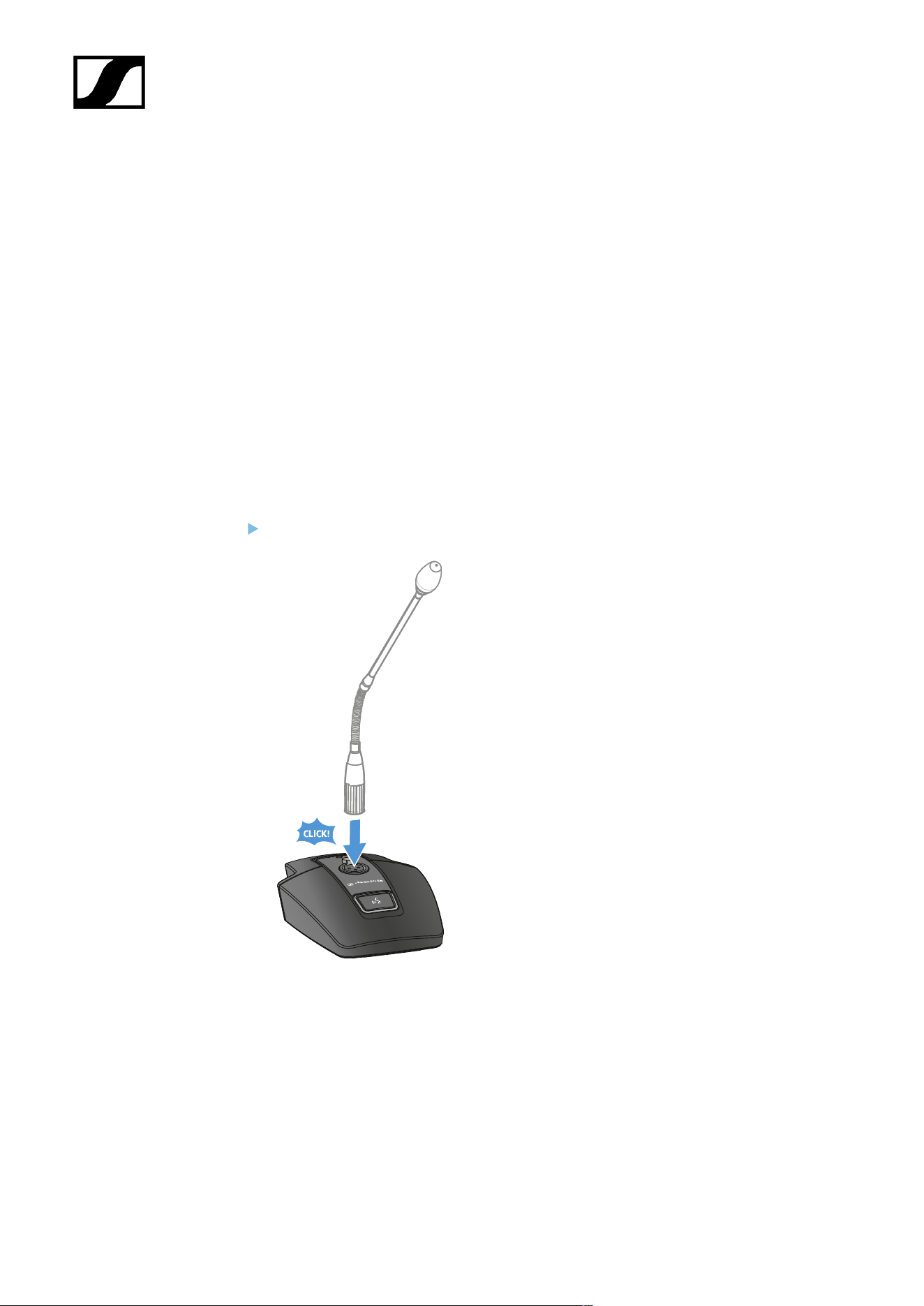
| 3 - Instruction manual
Connecting a gooseneck microphone
The following gooseneck microphone is compatible with the EW-DX TS 5-pin table stand:
• MEG 14-40-L-II B | Gooseneck microphone, 40 cm
The following gooseneck microphones are compatible with the EW-DX TS 3-pin table stand:
• MEG 14-40 B | Gooseneck microphone, 40 cm
• MZH 3015 | Gooseneck, 15 cm
• MZH 3040 | Gooseneck, 40 cm
• MZH 3042 | Gooseneck, 40 cm
• ME 34 | Condenser microphone head
• ME 35 | Condenser microphone head
• ME 36 | Condenser microphone head
Plug the gooseneck microphone into the XLR socket until it locks into place.
436
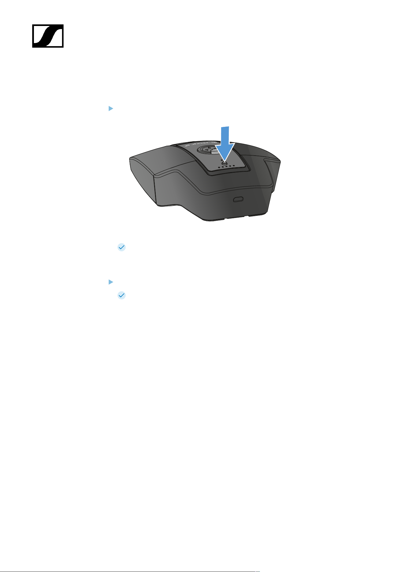
| 3 - Instruction manual
Switching the table stand on/off
To switch the table stand on:
Briefly press the ON/OFF button.
The MUTE button lights up green when a gooseneck microphone is connected.
To switch the table stand off:
Press and hold the ON/OFF button.
The MUTE button LED goes out.
437

| 3 - Instruction manual
Establishing a connection to the receiver
To establish a radio link between the transmitter and the receiver, the devices must be
synchronized.
See Establishing a radio link | Synchronizing the receiver and transmitter
Conditions and restrictions for using frequencies
There may be special conditions and restrictions for using frequencies in your
country.
Before putting the product into operation, find the information for your country
at the following address:
sennheiser.com/sifa
438
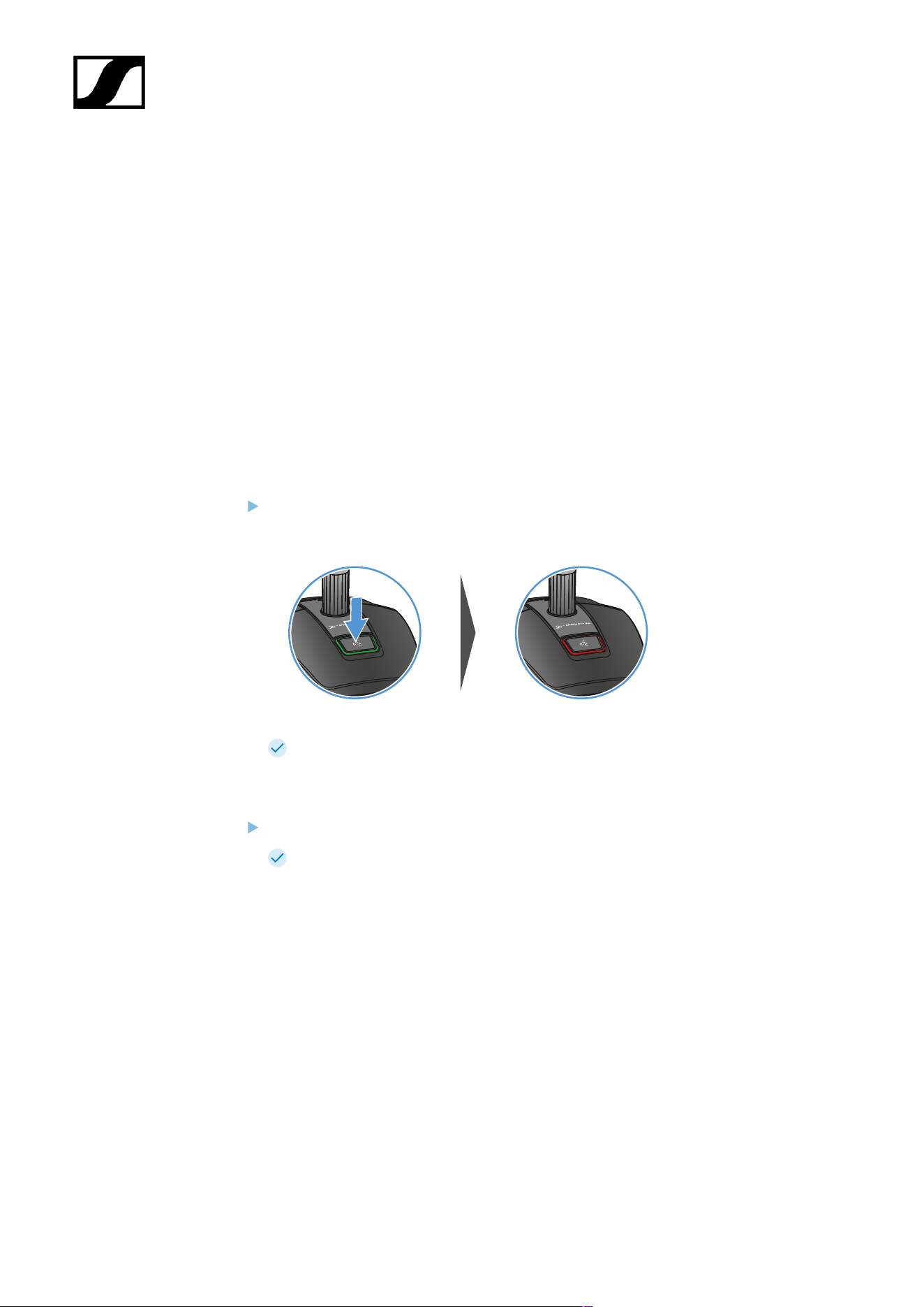
| 3 - Instruction manual
Muting the table stand
The MUTE button can have different functions:
• Disabled: The MUTE button has no function.
• AF Mute: The audio signal is muted when the MUTE button is pressed. Pressing the
button again activates the audio signal.
• PTT (Push to talk): Press and hold the MUTE button to activate the audio signal.
• PTM (Push to mute): Press and hold the MUTE button to mute the audio signal.
The function of the MUTE button can be configured in the Mute Mode menu item of the
receiver (see Ch 1 / Ch 2 -> Mute Mode menu item).
To activate muting:
Briefly press the MUTE button while the table stand is switched on and a gooseneck
microphone is connected.
The button lights up red.
To cancel the muting:
Briefly press the MUTE button again.
The button lights up green. The audio signal is activated.
439
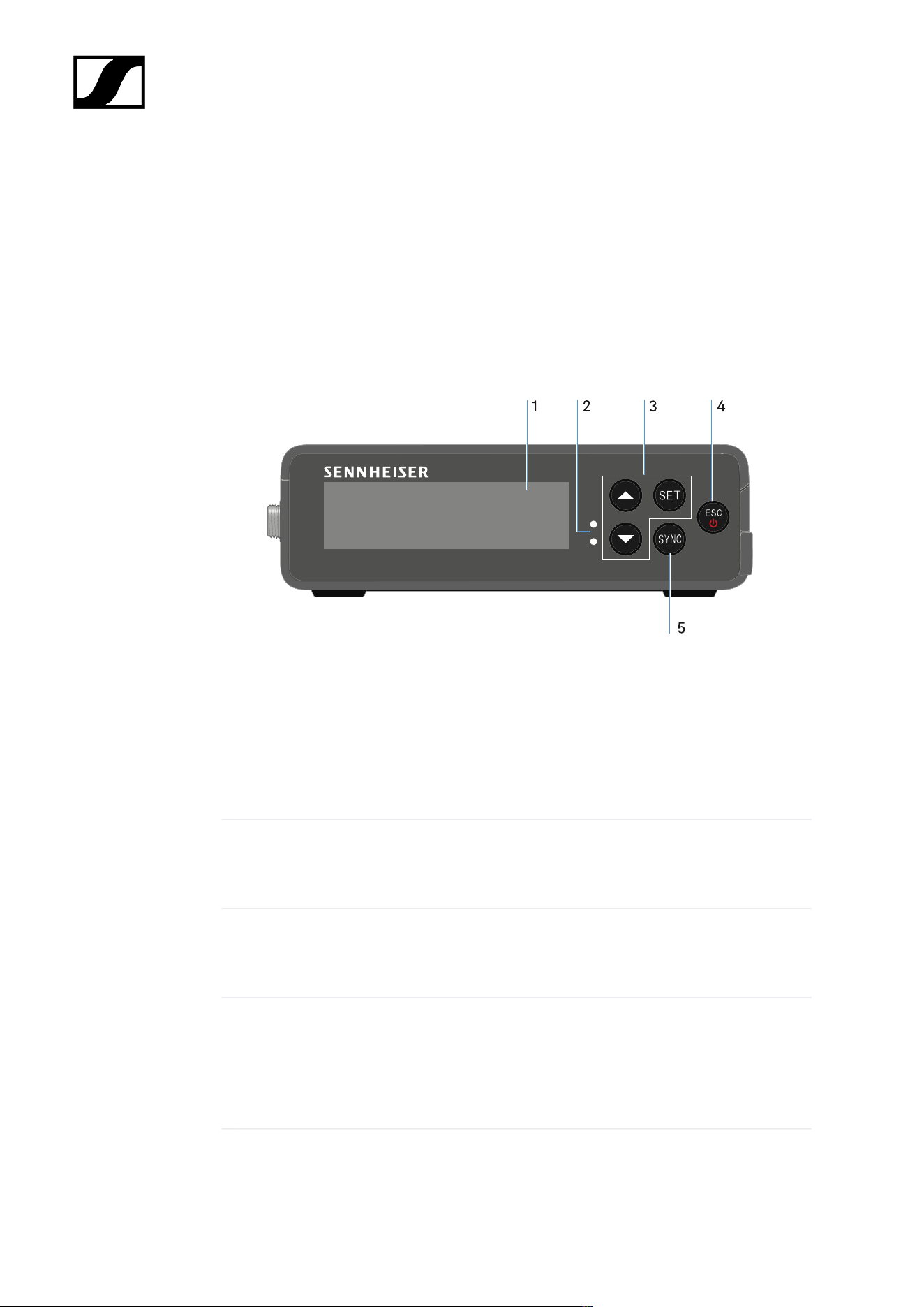
| 3 - Instruction manual
EW-DP EK portable receiver
Product overview
Front
1 Display for status information and operating menu
• See Meaning of the LEDs
2 LINK and DATA LEDs to indicate connection status and Bluetooth status
• See Meaning of the LEDs
3 UP/DOWN/SET menu buttons for navigating the operating menu
• See Buttons for navigating the menu
4 ESC/ON/OFF button for canceling an action in the menu or switching the device on and
off
• See Buttons for navigating the menu
• See Buttons for navigating the menu
440
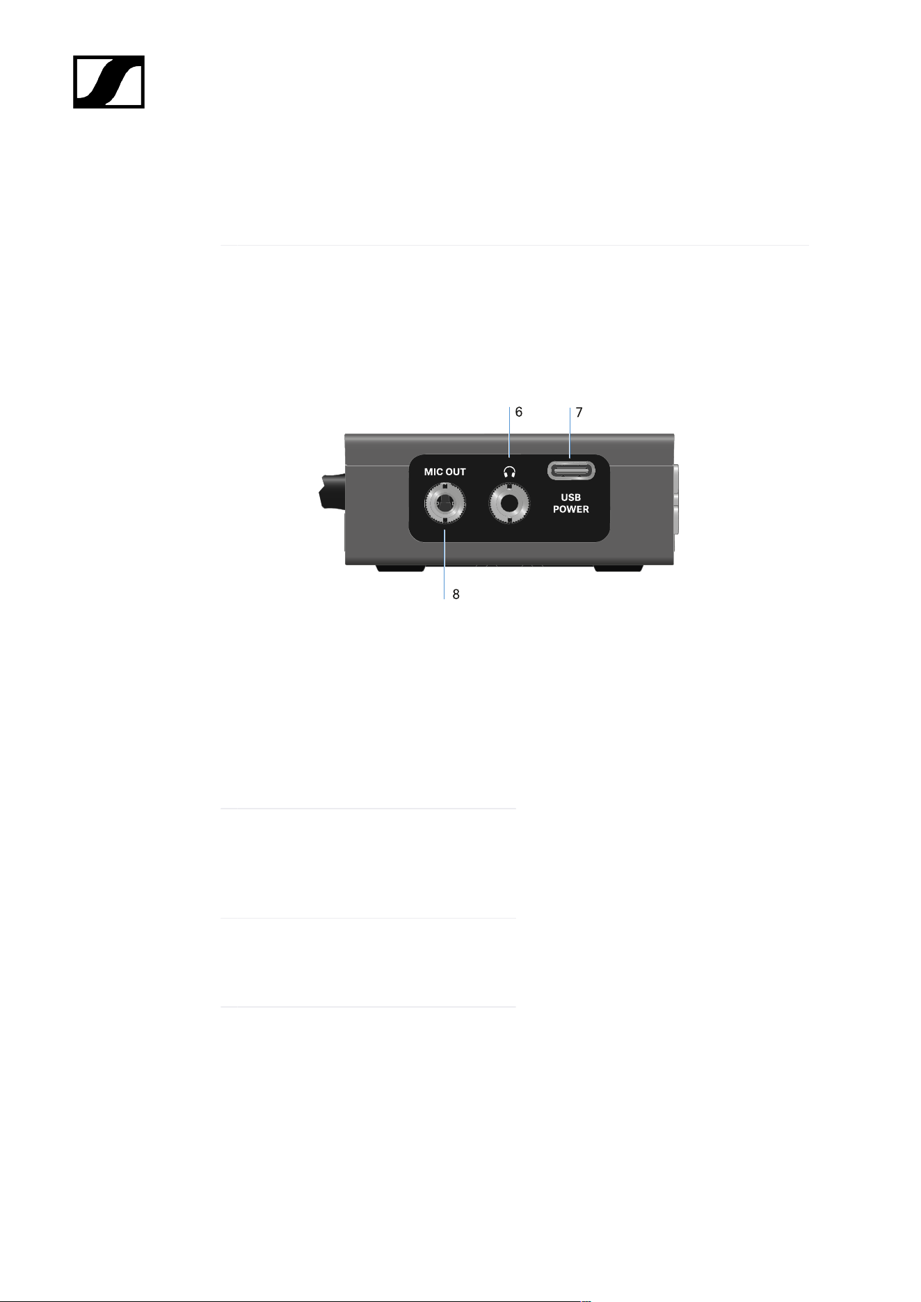
| 3 - Instruction manual
5 SYNC button for synchronizing the transmitter and receiver
• See Establishing a radio link | Synchronizing the receiver and transmitter
page
6 3.5 mm jack socket for headphones
• See Outputting audio signals
7 USB-C connection socket for power
supply
• See Power supply
8 3.5 mm jack socket for connecting cable
• See Outputting audio signals
441
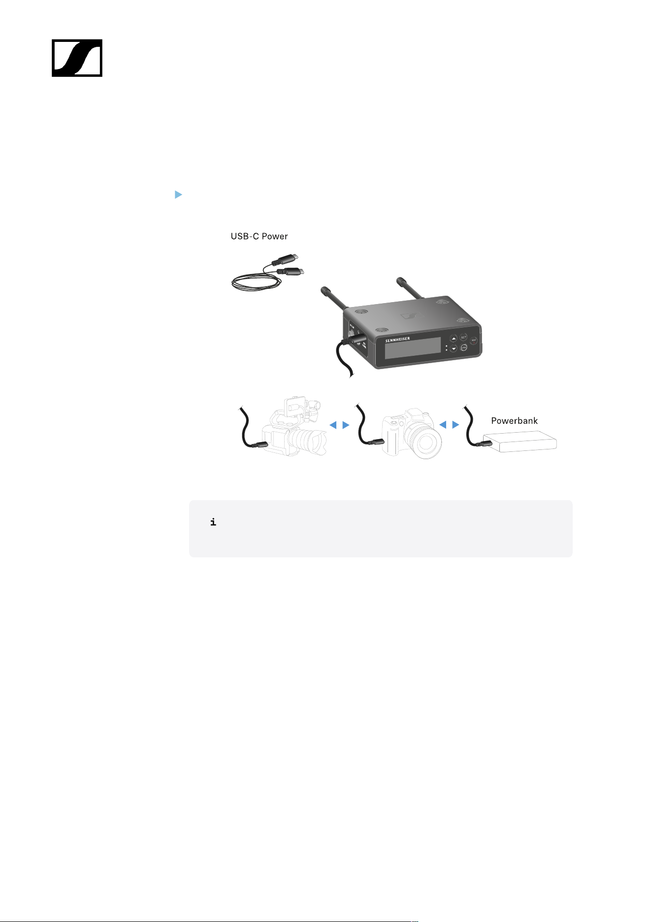
| 3 - Instruction manual
Power supply
The EW-DP EK can be powered in two different ways:
Power supply via USB-C from a camera or power bank
Connect the receiver to a camera or other power supply using a USB-C cable.
Power supply via USB-C cable: 5 V/min. 1 A (for max. charging speed of
the inserted BA 70)
442
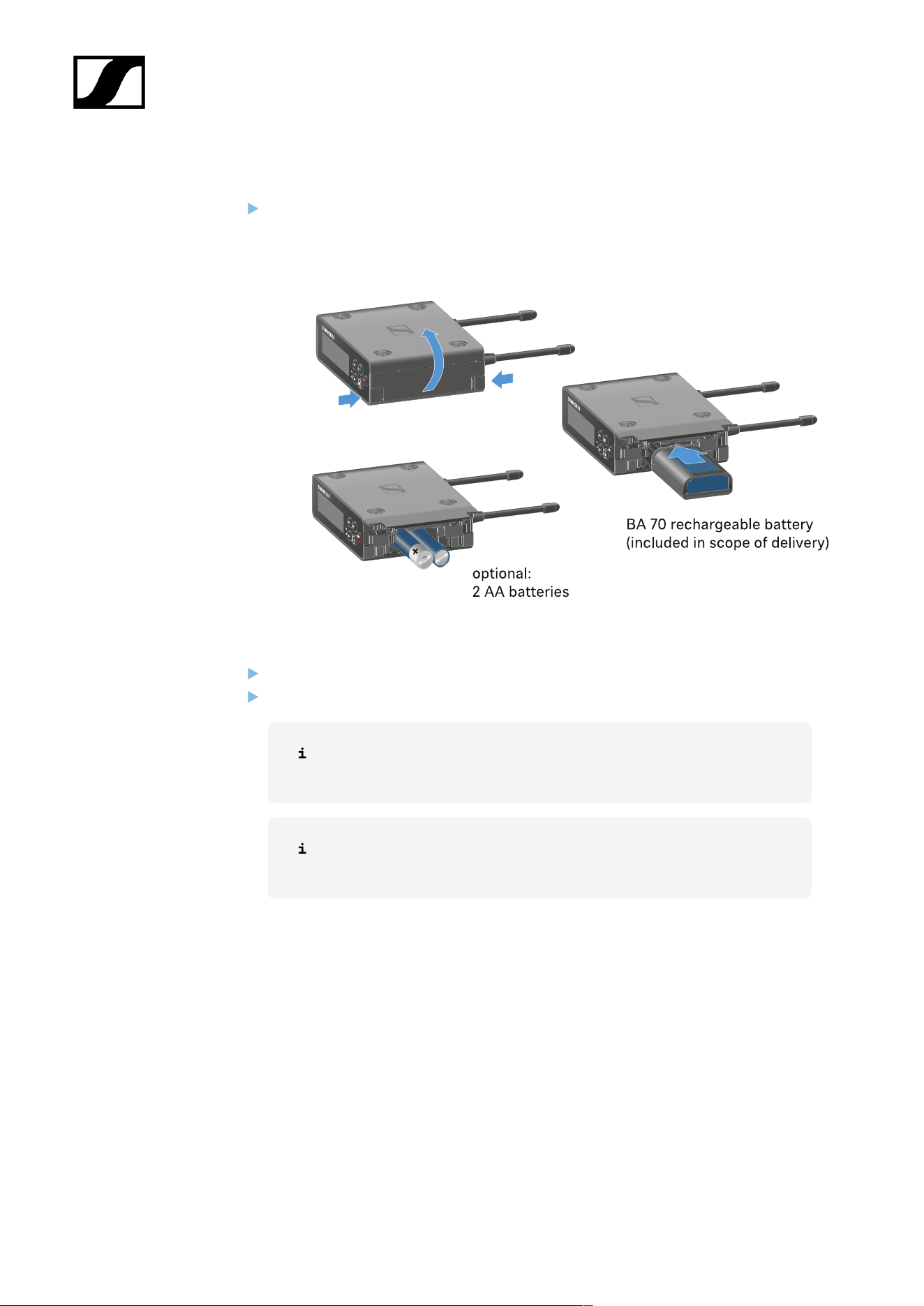
| 3 - Instruction manual
Power supply via (rechargeable) batteries
Open the EW-DP EK unit’s battery compartment by pressing in the two release
buttons on the sides.
Insert either a BA 70 rechargeable battery or 2 AA batteries.
Close the battery compartment.
Primary batteries and USB can be used in parallel without restrictions, as
this is controlled by the EK unit.
The EW-DP EK supports the USB Power Delivery Protocol for smart USB-
C power supply units (USB-C PD).
443
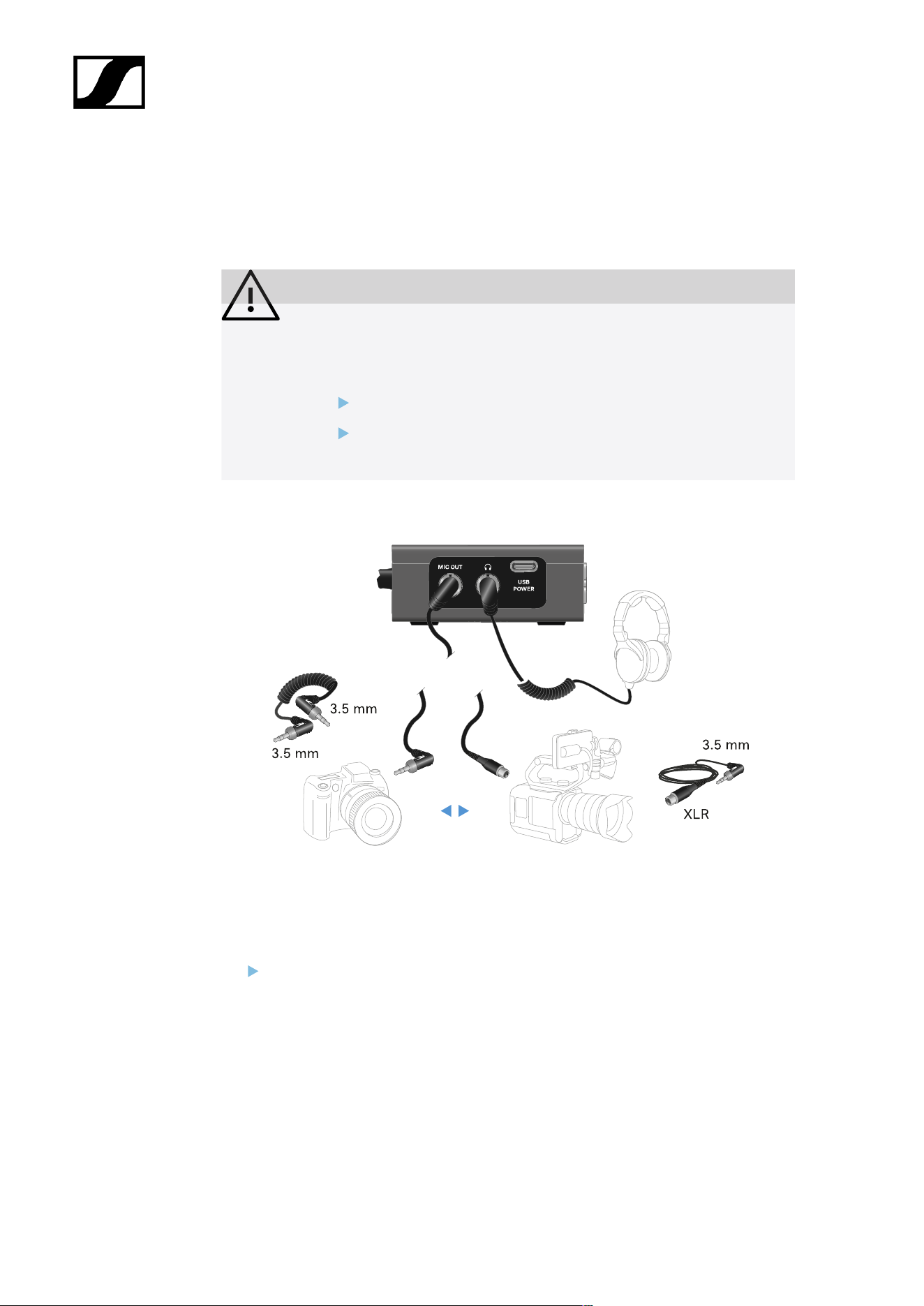
| 3 - Instruction manual
Outputting audio signals
The EW-DP EK has an unbalanced 3.5 mm audio output and an unbalanced 3.5 mm
headphone output.
CAUTION
Hearing damage due to high volumes
The product is capable of producing high sound pressure levels. Higher
volumes or longer durations can damage your hearing.
Set the volume to a medium level.
Reduce the volume level before changing a transmitter or a
frequency.
To connect a 3.5 mm jack cable:
Plug the jack cable into the MIC OUT socket on the EW-DP EK.
444

| 3 - Instruction manual
The hot shoe adapter can be fitted to the mounting plate in different positions according to
the mounting situation.
To mount the hot shoe adapter on the mounting plate:
Pre-assemble the hot shoe adapter by connecting the adapter and lever using the
supplied screw.
Then screw the hot shoe adapter to the mounting plate at the desired location.
446
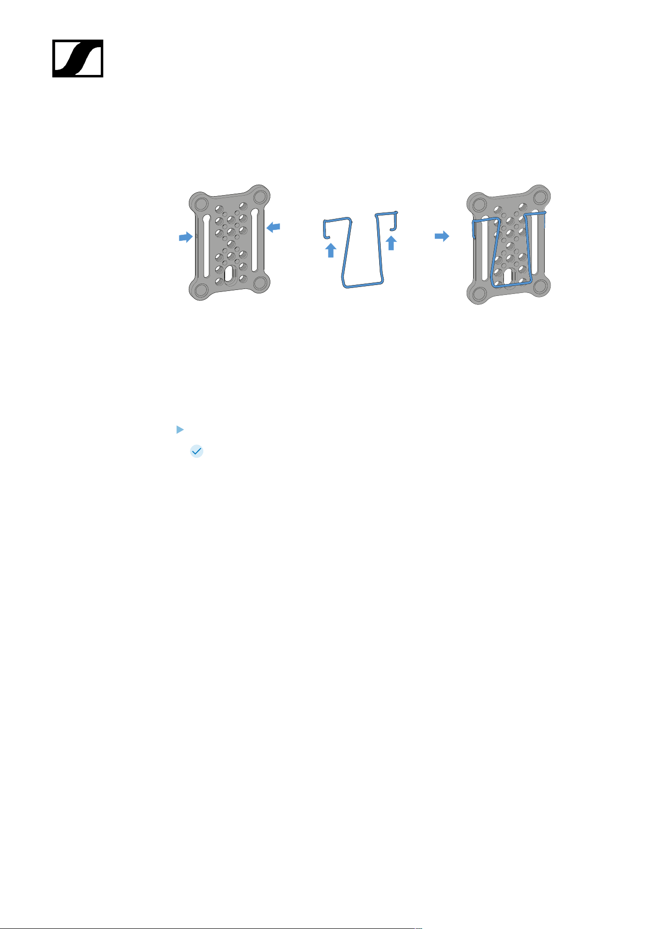
| 3 - Instruction manual
Mounting plate and clip
As an alternative to the hot shoe adapter, a metal clip can be attached to the side of the
mounting plate.
To mount the clip on the mounting plate:
Insert the clip into the side of the mounting plate as shown.
This enables you to attach the receiver to belts or pockets using the mounting
plate.
447
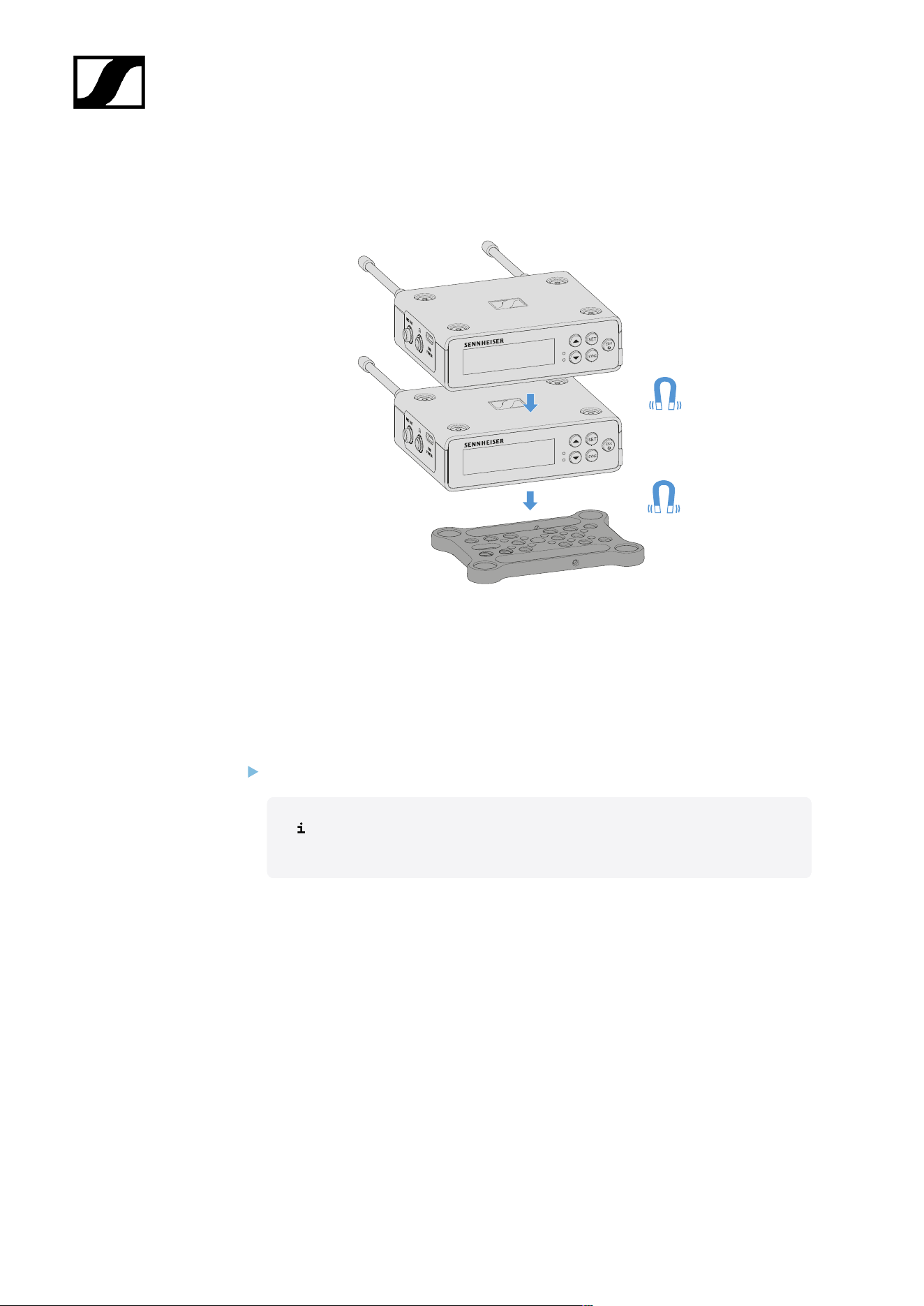
| 3 - Instruction manual
Mounting/stacking receivers on the mounting plate
The receiver has magnets on the bottom, which means you can simply place it on the
mounting plate without the need for an additional screw connection. This allows you to stack
two receivers on top of one another.
To mount the receiver on the mounting plate:
Insert the receiver’s four magnetic feet into the recesses on the mounting plate.
Two stacked receivers can be connected to one another using a Y-cable.
See “Cables for EW-DP EK”
448
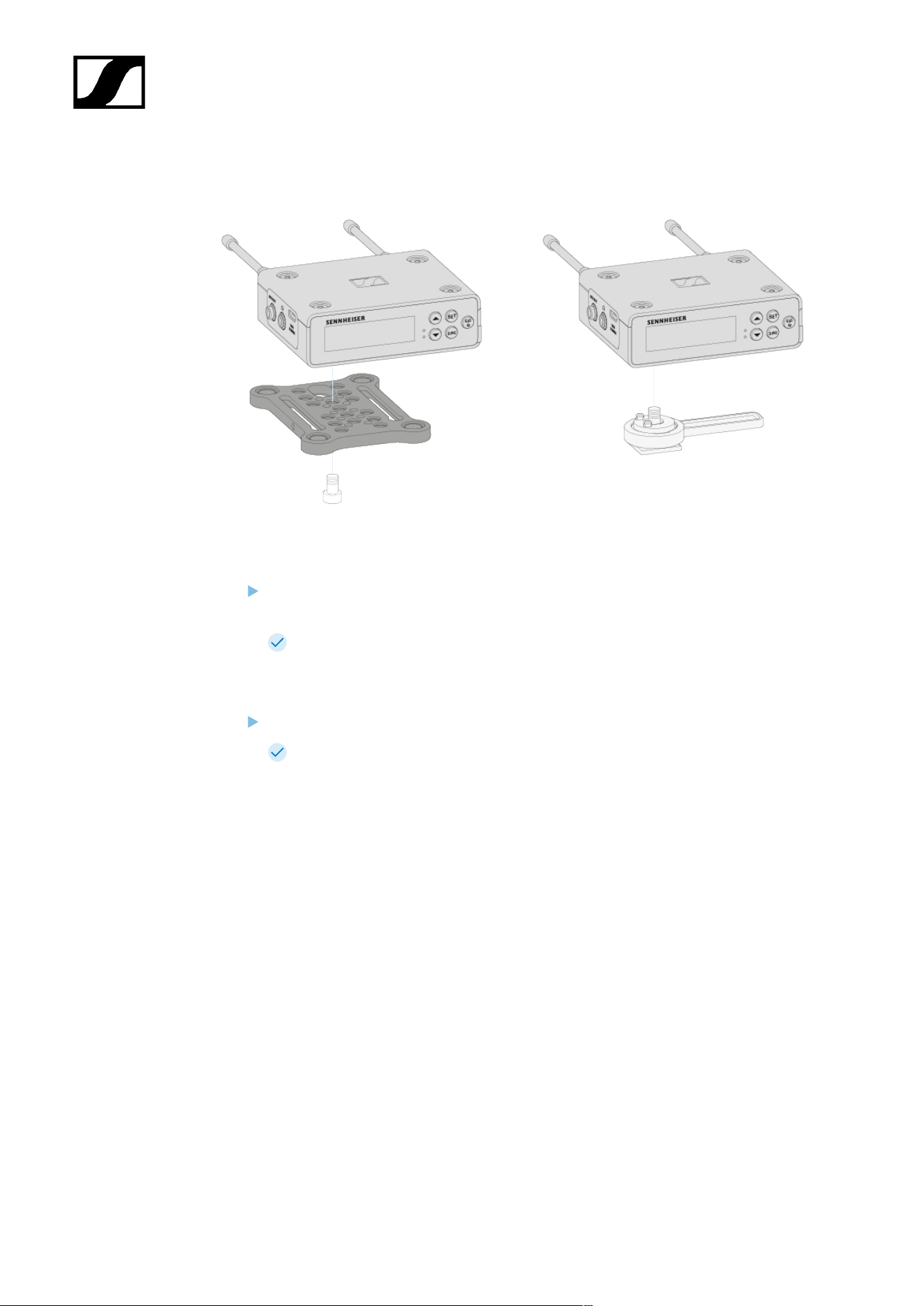
| 3 - Instruction manual
Mounting with or without the mounting plate in a rotated position
To mount the receiver with the mounting plate rotated by 90°:
Turn the mounting plate by 90° and screw it to the bottom of the receiver in the
desired position.
This mounting variant is particularly suitable for attaching with a clip.
To mount the receiver without a mounting plate:
Screw the hot shoe adapter directly to the bottom of the receiver.
It can now be attached to a camera’s hot shoe.
449
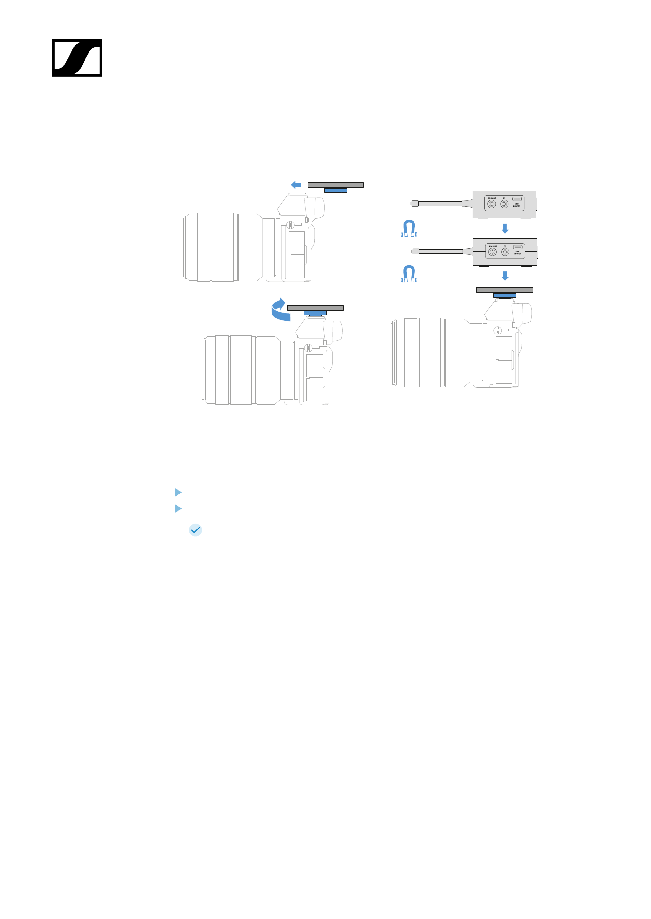
| 3 - Instruction manual
Example for mounting on a DSLR or video camera
To mount the mounting plate with hot shoe adapter on a DSLR or video camera:
Slide the adapter into the camera’s hot shoe.
Rotate the lever on the hot shoe adapter until the adapter is tightly attached.
Now you can attach one or two receivers to the mounting plate.
450
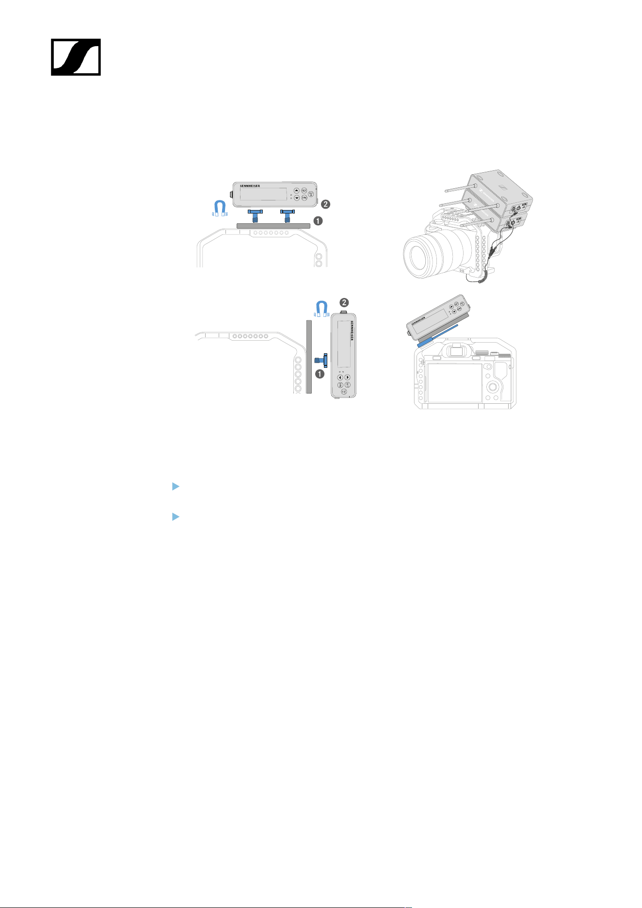
| 3 - Instruction manual
Example for mounting on camera cages
To attach the mounting plate to a camera cage:
Screw the mounting plate to the camera cage using one or two screws, depending on
the mounting situation and position.
Attach the receiver to the mounting plate.
451
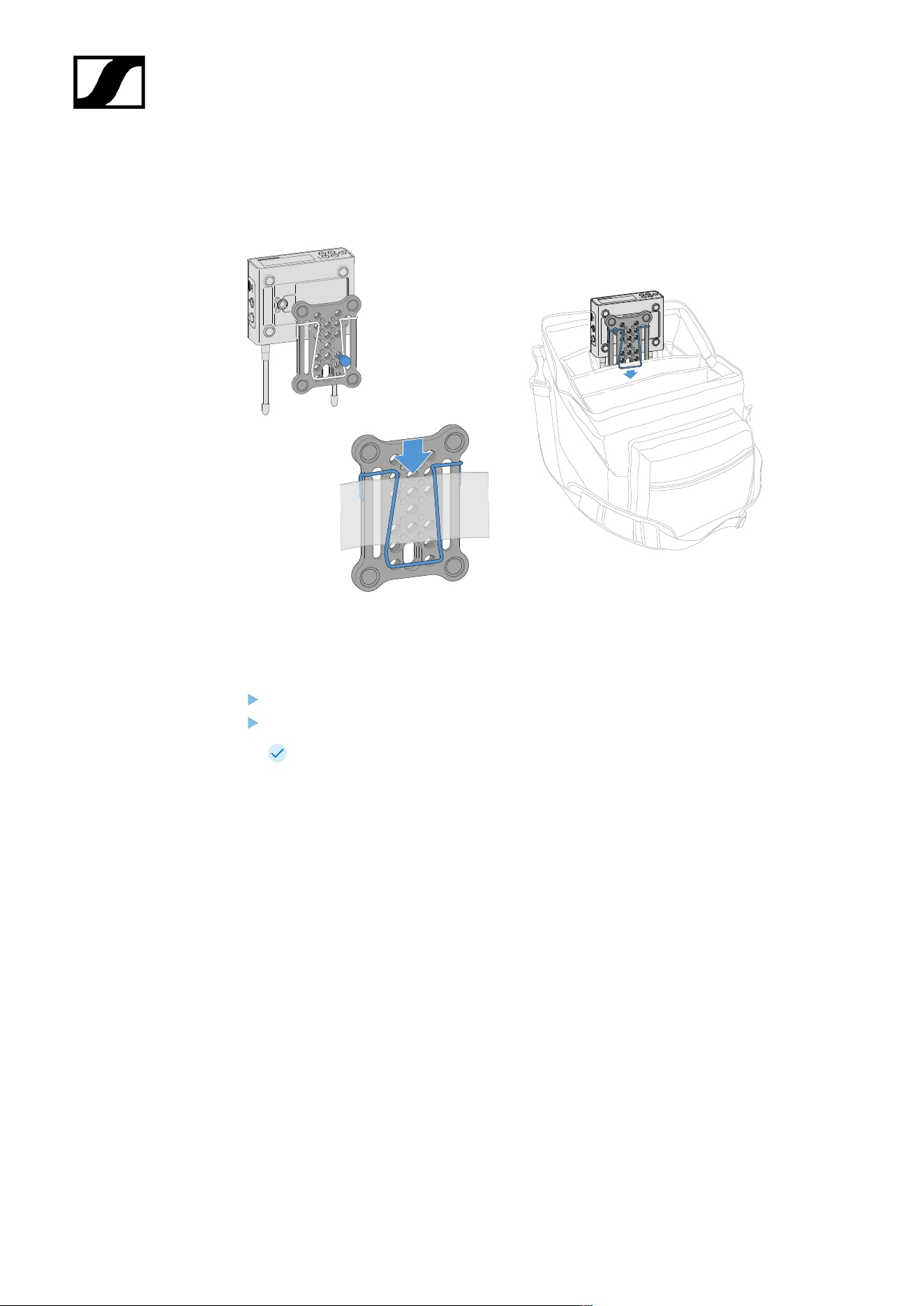
| 3 - Instruction manual
Example for attaching to pockets and belts
To fasten the receiver with mounting plate to pockets or belts:
Attach the clip to the mounting plate.
Attach the mounting plate to the receiver by inserting a screw through the slot.
You can now clip the receiver to belts or pockets.
452
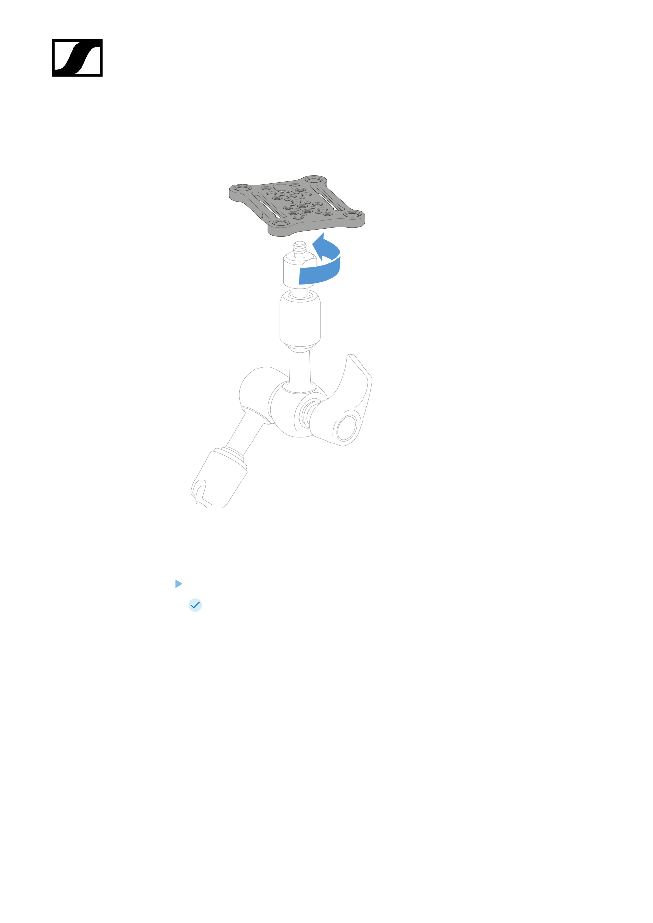
| 3 - Instruction manual
Example for mounting on tripods
To fasten the mounting plate to a tripod:
Screw the mounting plate onto the tripod thread at the desired position.
Now you can attach one or two receivers to the mounting plate.
453
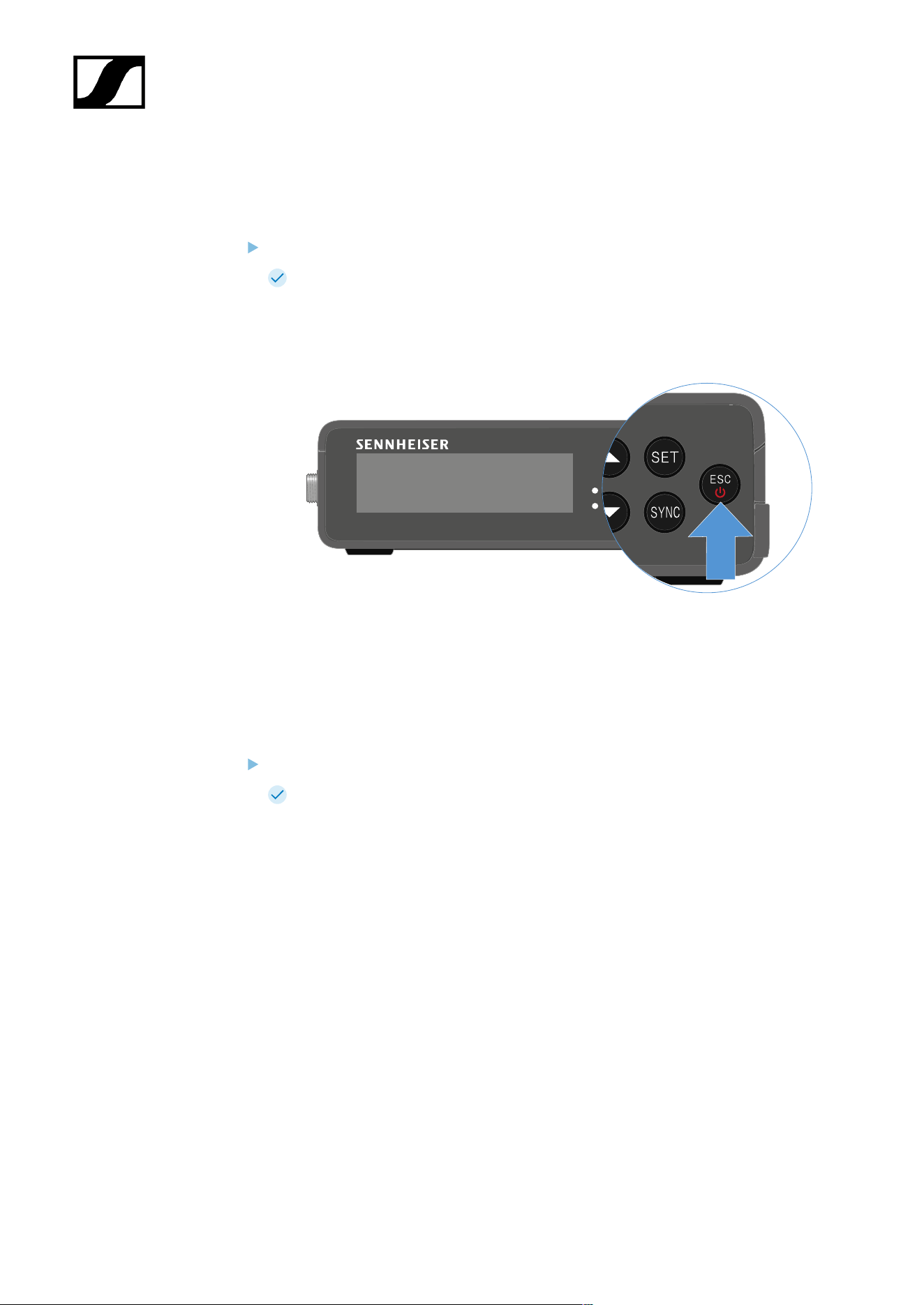
| 3 - Instruction manual
Switching the receiver on and off
To switch the receiver on:
Short-press the ON/OFF button.
The receiver switches on.
To switch the receiver off:
Press the ON/OFF button.
The receiver switches off.
454
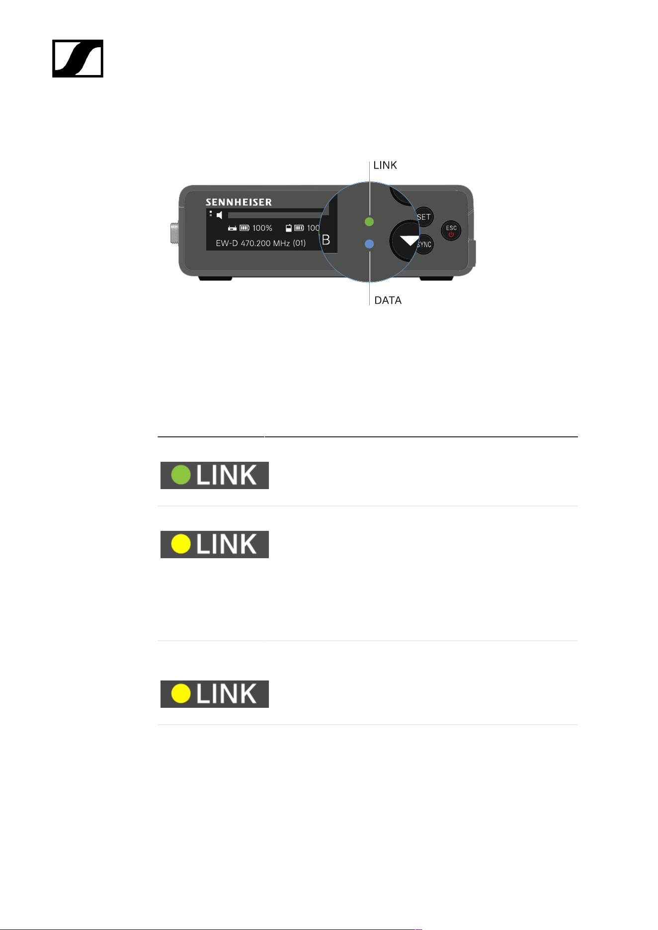
| 3 - Instruction manual
Meaning of the LEDs
The LINK and DATA LEDs on the front of the receiver can indicate the following information.
LINK LED
The LINK LED provides information about the status of the radio link between the transmitter
and receiver, as well as status information for the paired transmitter.
The LED is green:
• The link between the transmitter and receiver is established.
• The audio signal is active.
The LED is yellow:
• The link between the transmitter and receiver is established.
• The audio signal is muted.
or
• No microphone module is mounted on the SKM-S handheld
transmitter.
The LED is flashing
yellow:
• The link between the transmitter and receiver is established.
• The audio signal is overdriven (clipping).
The LED is
continuously red:
• No link between the transmitter and receiver.
455
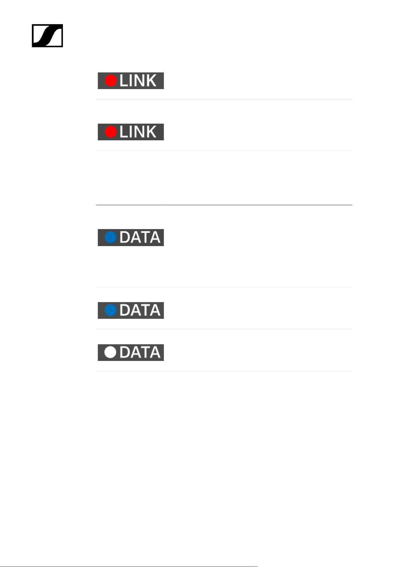
| 3 - Instruction manual
The LED is flashing
red:
• The battery/rechargeable battery in the paired transmitter is
low.
DATA LED
The DATA LED provides information on the receiver’s Bluetooth Low Energy link to the
Smart Assist app and on the synchronization of transmitters and receivers.
The LED is flashing
blue:
• The Bluetooth Low Energy link is being established
between the receiver and a smartphone or tablet with the
Smart Assist app.
or
• The receiver is being synchronized with a transmitter.
The LED is blue:
• The firmware is being updated.
The LED is off:
• Normal operation
• There is currently no active data link.
456
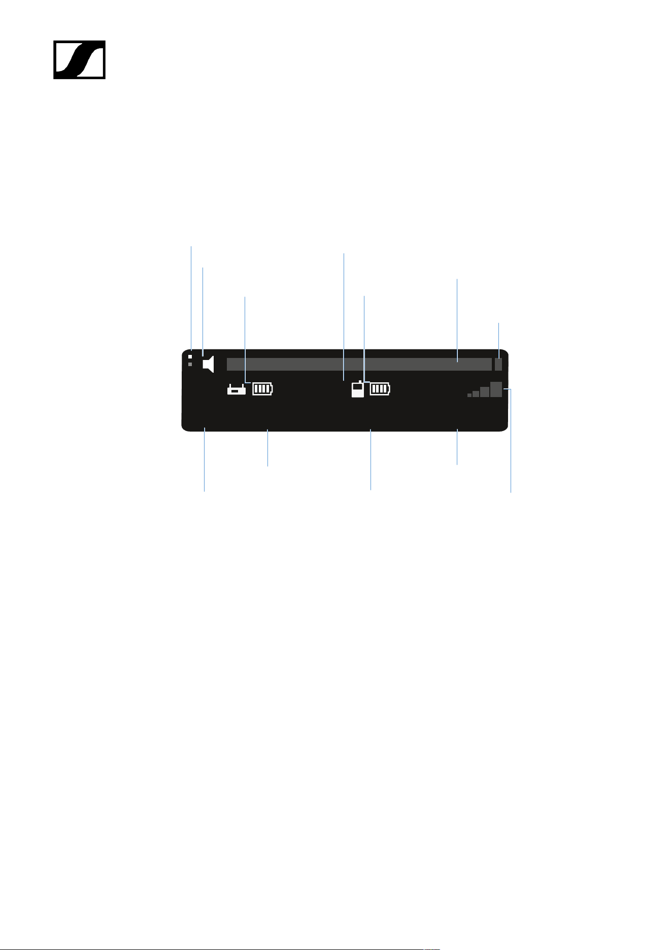
| 3 - Instruction manual
Displays on the receiver’s display panel
Status information such as frequency, reception quality, battery status and audio level is
shown on the display.
The display also shows the operating menu, which you can use to configure all of the settings
(see Buttons for navigating the menu).
EW-D
(01)
470.200 MHz
7:30h
12:00h
+18 dB
Channel
Transmitter
audio level
Gain
Transmitter
battery
(SK / SKM-S)
Frequency
Mute switch
Receiver
battery (EK)
Display page
Radio
frequency
level
Link name
PEAK
display
Further information
Display page:
• Main view and advanced view
Mute / mute switch:
• MUTE SWITCH menu item | Muting the handheld transmitter | Muting the bodypack
transmitter
Link name:
• Can be changed in the Smart Assist app.
• Connecting to the app:
• Smart Assist app
Receiver battery:
• Power supply
457
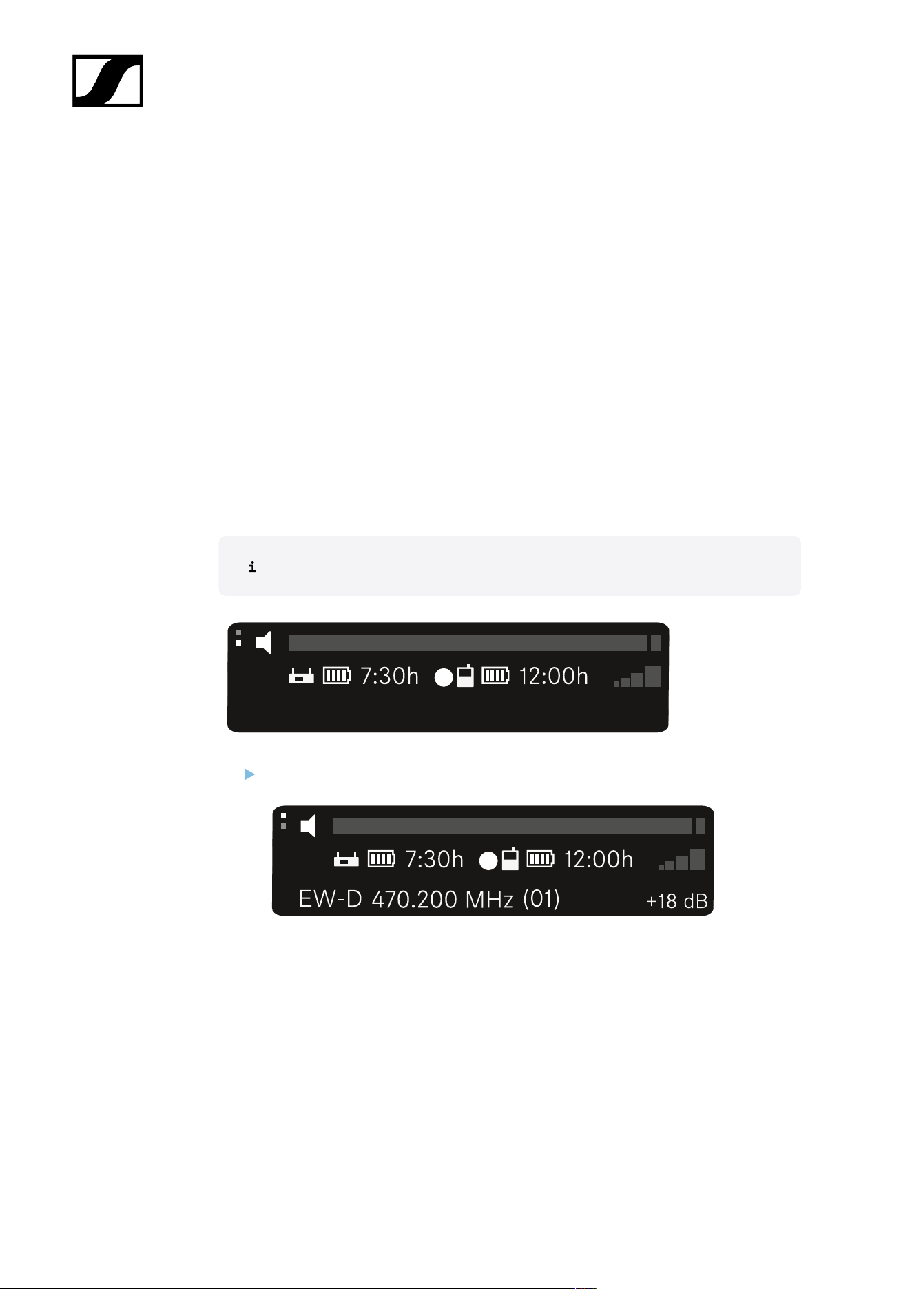
| 3 - Instruction manual
Transmitter battery
• SKM-S: Inserting and removing the batteries/rechargeable batteries | SK: Inserting
and removing the batteries/rechargeable batteries
Frequency/channel:
• CHANNEL menu item
Gain/transmitter audio level/PEAK indicator
• AF OUT menu item
Signal level:
• GAIN menu item
Main view and advanced view
After the device switches on, the display shows the main view.
Press the UP button to access the advanced view.
458
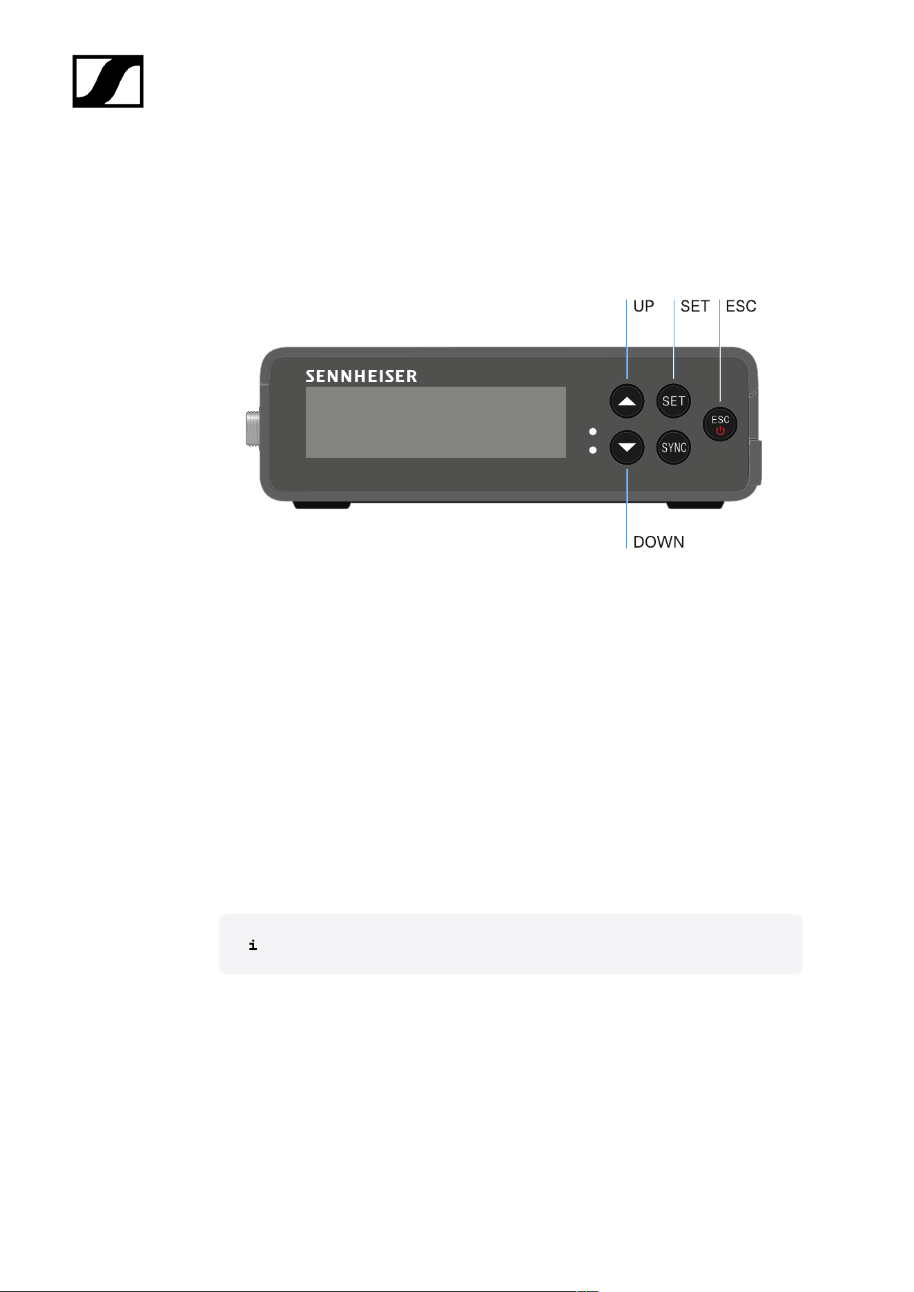
| 3 - Instruction manual
Buttons for navigating the menu
Use the following buttons to navigate through the receiver’s operating menu.
Press the SET button
• Open the menu
• Save settings in a menu item
Press the UP or DOWN button
• Changes to the previous or next menu item
• Changes the setting of a menu item
Press the ESC button
• Cancel input
Opening the menu and navigating the menu items
459
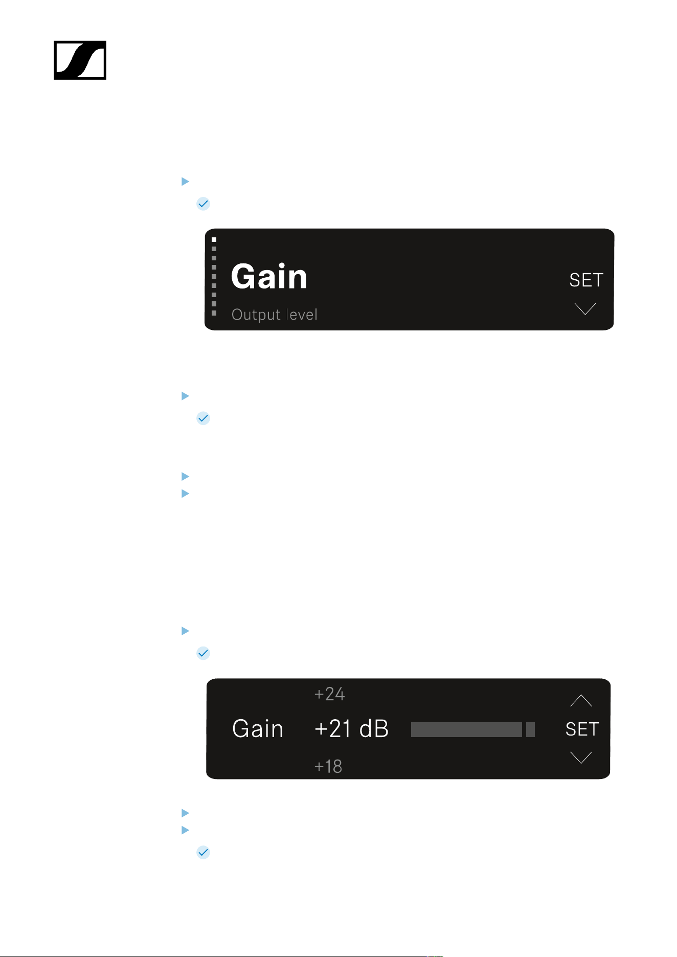
| 3 - Instruction manual
Opening the menu and navigating the menu items
To open the main menu:
Press the SET button.
The first menu item GAIN flashes.
To navigate the menu items:
Press the UP and DOWN buttons.
The currently active menu item appears in the display.
To open a menu item:
Navigate to the desired menu item until it flashes.
Press the SET button to open the selected menu item.
GAIN menu item
Under the GAIN menu item, you can set the level of the audio signal coming from the paired
transmitter.
Open the GAIN menu item.
The display looks as follows.
Press the UP or DOWN button to adjust the value.
Press the SET button to save the set value.
You will then be returned to the main view or advanced view.
460
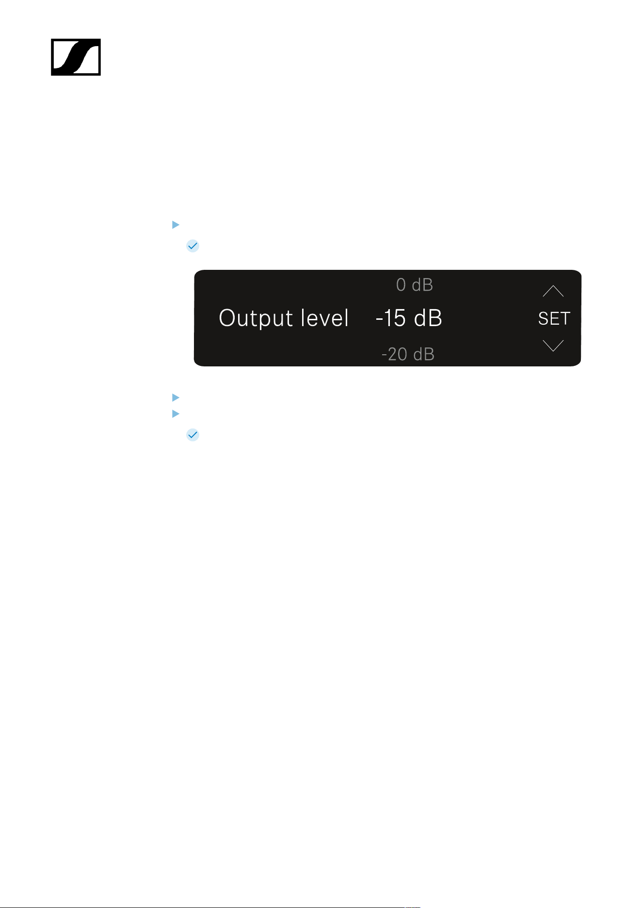
| 3 - Instruction manual
OUTPUT LEVEL menu item
Under the OUTPUT LEVEL menu item, you can set the level of the audio signal coming from
the receiver’s audio outputs. This audio signal can be output to a camera input or a mixing
console, for example.
Open the OUTPUT LEVEL menu item.
The display looks as follows.
Press the UP or DOWN button to adjust the value.
Press the SET button to save the set value.
You will then be returned to the main view or advanced view.
461
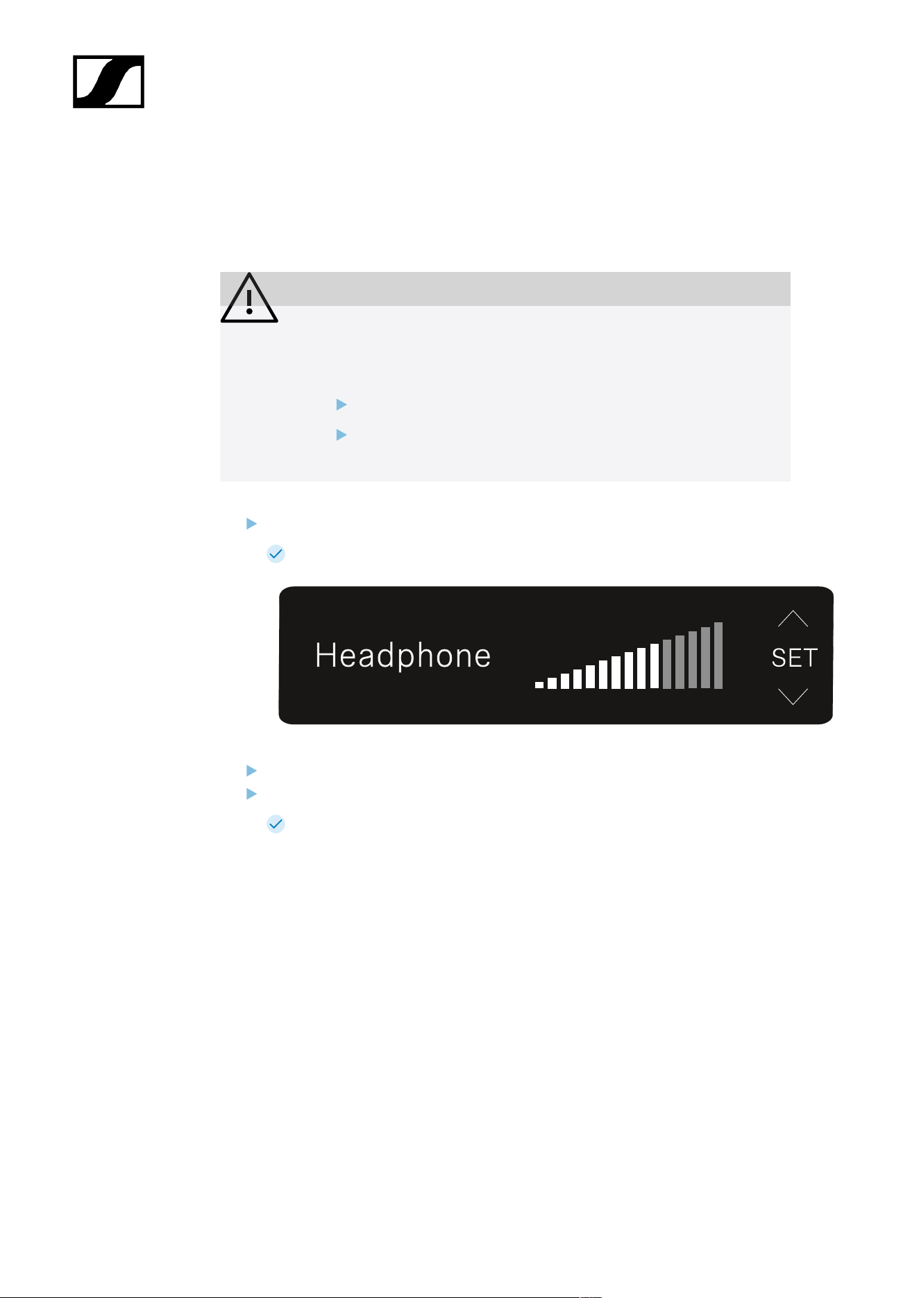
| 3 - Instruction manual
HEADPHONE menu item
Under the HEADPHONE menu item, you can set the volume of the audio signal coming from
the receiver’s headphone output.
CAUTION
Hearing damage due to high volumes
The product is capable of producing high sound pressure levels. Higher
volumes or longer durations can damage your hearing.
Set the volume to a medium level.
Reduce the volume level before changing a transmitter or a
frequency.
Open the HEADPHONE menu item.
The display looks as follows.
Press the UP or DOWN button to adjust the value.
Press the SET button to save the set value.
You will then be returned to the main view or advanced view.
462
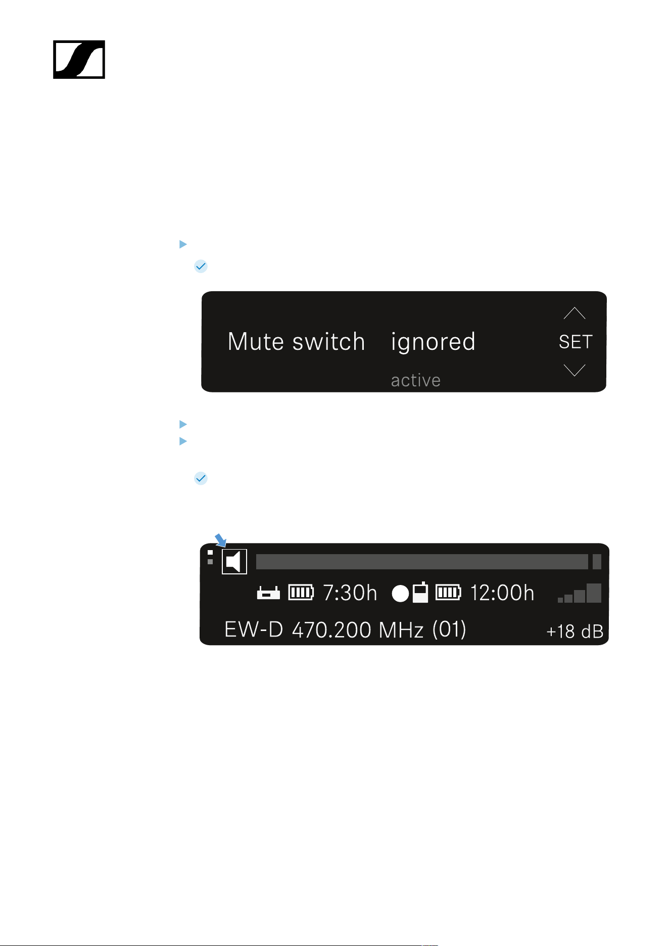
| 3 - Instruction manual
MUTE SWITCH menu item
Under the MUTE SWITCH menu item, you can disable the mute switch on the paired
transmitter.
The transmitter can then no longer be muted.
Open the MUTE SWITCH menu item.
The display looks as follows.
Press the UP or DOWN button to enable (active) or disable (ignored) the function.
Press the SET button to save the set value. You will then be returned to the main view
or advanced view.
You will then be returned to the main view or advanced view.
If a loudspeaker icon within a border appears on the upper left of the display, the
transmitter’s mute switch is activated.
463
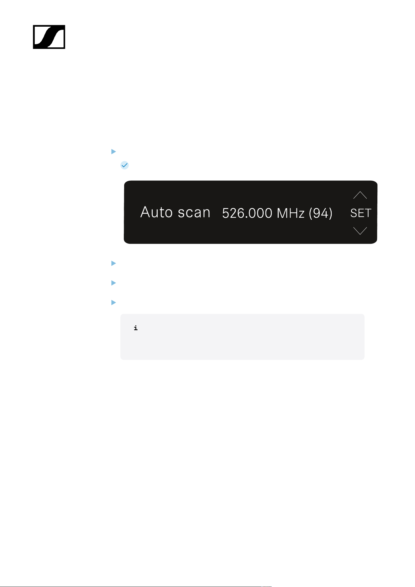
| 3 - Instruction manual
AUTO SCAN menu item
Under the AUTO SCAN menu item, you can perform an automatic frequency scan of your
area. This enables you to easily find and assign free radio frequencies.
The scan starts at the lowest frequency in the device’s frequency range.
Open the AUTO SCAN menu item.
The scan starts automatically. The next free frequency is shown on the display.
Press the SET button to accept the displayed frequency.
Or
Press the UP or DOWN button to display the next free frequency.
Or
Press the ESC button to cancel the scan. The previous frequency remains unchanged.
If you have set a new frequency, you must still synchronize the receiver
with the transmitter to establish the radio link (see Establishing a radio
link | Synchronizing the receiver and transmitter).
464
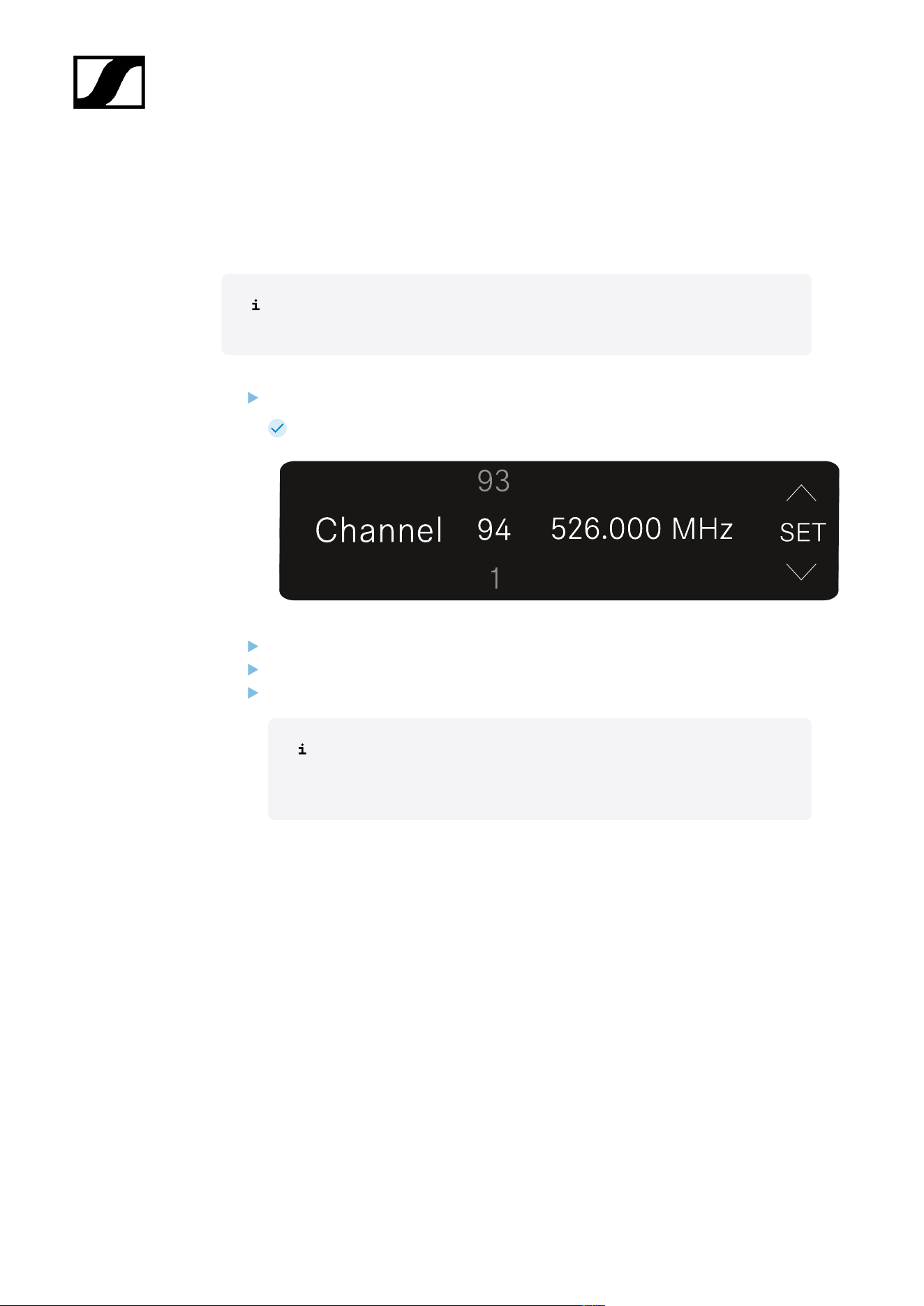
| 3 - Instruction manual
CHANNEL menu item
Under the CHANNEL menu item, you can set the radio frequency by selecting a preset
channel.
If you are not sure whether the selected frequency is free, we recommend
performing a scan to detect all free frequencies: AUTO SCAN menu item.
Open the CHANNEL menu item.
The display looks as follows.
Press the UP or DOWN button to select a preset channel.
Press the SET button to accept the displayed frequency.
Press the ESC button to cancel the scan. The previous frequency remains unchanged.
If you have set a new frequency, you must still synchronize the receiver
with the transmitter to establish the radio link (see Establishing a radio
link | Synchronizing the receiver and transmitter).
465
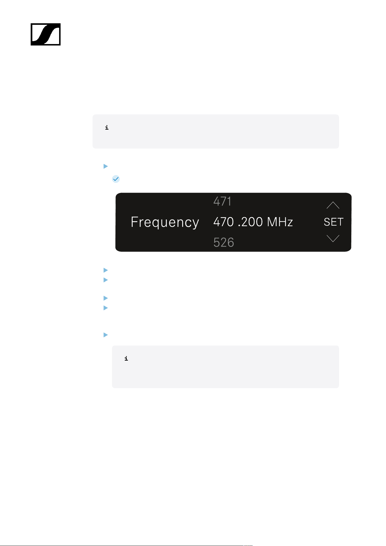
| 3 - Instruction manual
FREQUENCY menu item
Under the FREQUENCY menu item, you can manually set the radio frequency independently
of the preset channels.
If you are not sure whether the selected frequency is free, we recommend
performing a scan to detect all free frequencies: AUTO SCAN menu item.
Open the FREQUENCY menu item.
The display looks as follows.
Press the UP or DOWN button to set the frequency in the megahertz range.
Press the SET button to select the value and activate fine-tuning of the frequency in
the kilohertz range.
Press the UP or DOWN buttons to finely adjust the frequency in the kilohertz range.
Press the SET button to accept the displayed frequency. You will then be returned to
the main view or advanced view.
Or
Press the ESC button to cancel the scan. The previous frequency remains unchanged.
If you have set a new frequency, you must still synchronize the receiver
with the transmitter to establish the radio link (see Establishing a radio
link | Synchronizing the receiver and transmitter).
466
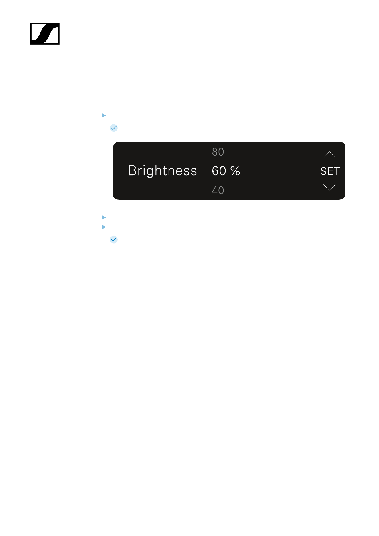
| 3 - Instruction manual
BRIGHTNESS menu item
Under the BRIGHTNESS menu item, you can set the brightness of the display.
Open the BRIGHTNESS menu item.
The display looks as follows.
Press the UP or DOWN button to set the desired brightness.
Press the SET button to save the set value.
You will then be returned to the main view or advanced view.
467

| 3 - Instruction manual
RESET menu item
Under the RESET menu item, you can reset the receiver to its factory settings.
Open the RESET menu item.
The display looks as follows.
Press the SET or ESC button to switch between the options YES and NO.
• YES: The receiver is reset to its factory settings.
• NO: The receiver is not reset.
You will then be returned to the main view or advanced view.
468
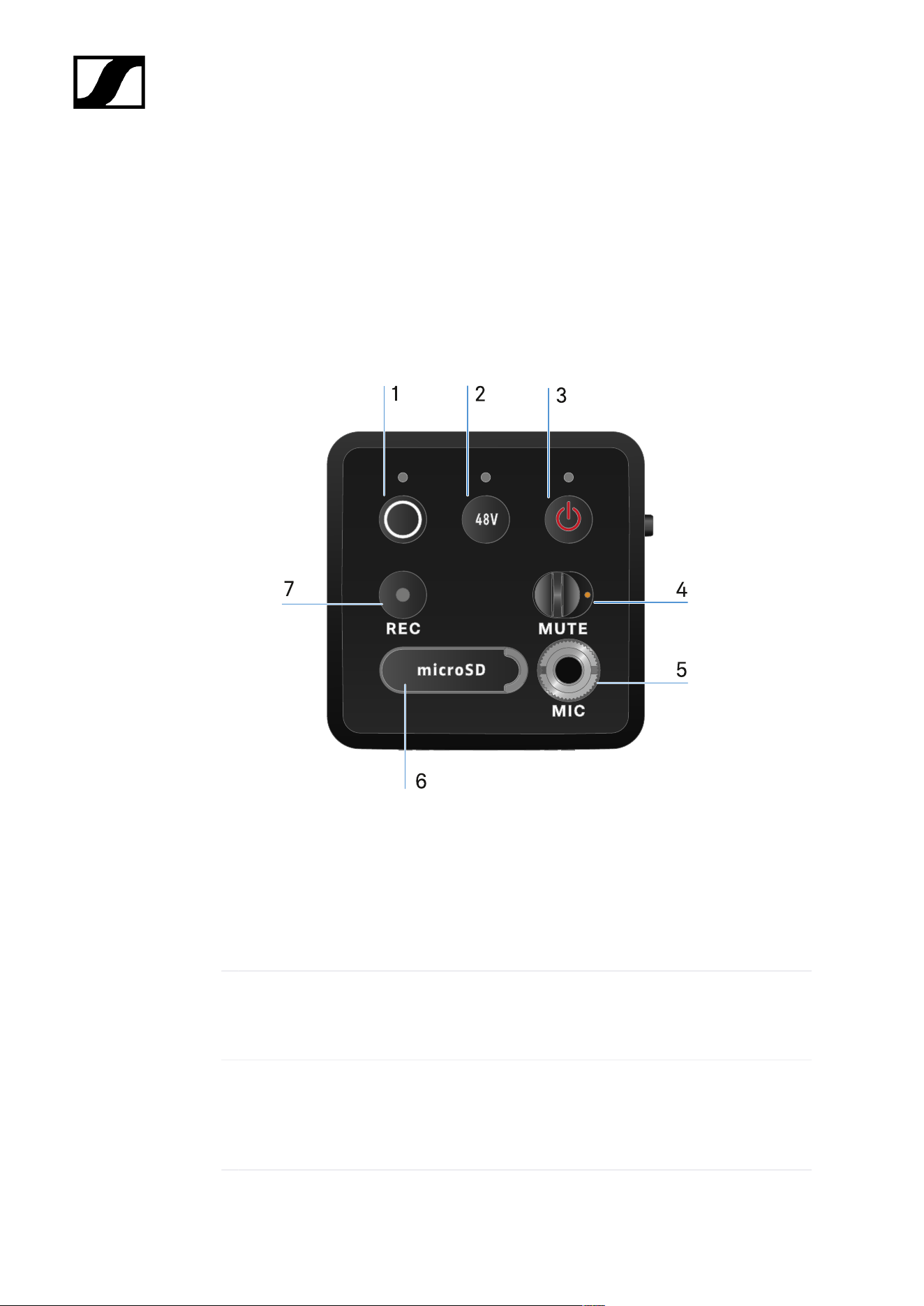
| 3 - Instruction manual
EW-DP SKP plug-on transmitter
Product overview
Front
1 SYNC button for synchronizing the transmitter and receiver
• See Establishing a radio link | Synchronizing the receiver and transmitter
• See Meaning of the LEDs
2 PHANTOM POWER button to turn phantom power P48 on/off
• See Meaning of the LEDs
3 ESC/ON/OFF button for canceling an action in the menu or switching the device on and
off
• See Switching the plug-on transmitter on and off
469
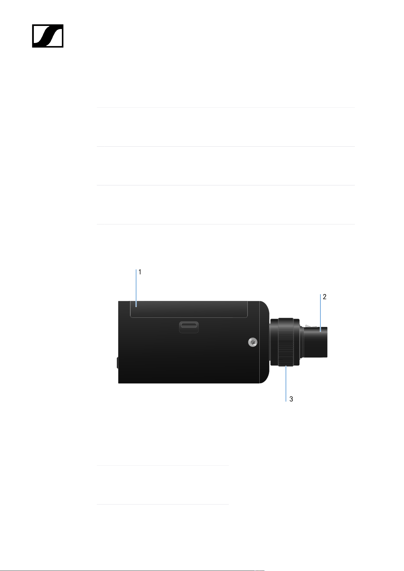
| 3 - Instruction manual
4 MUTE switch to mute or activate the audio signal
• See MUTE mode
5 3.5 mm jack input for clip-on microphones
• See Connecting a lavalier microphone
6 Slot for microSD cards
• See Using a microSD card
7 REC button
• See Starting/stopping recording
page
1 Battery compartment
• See Power supply
2 3-pin XLR plug
• See Attaching an XLR microphone
470

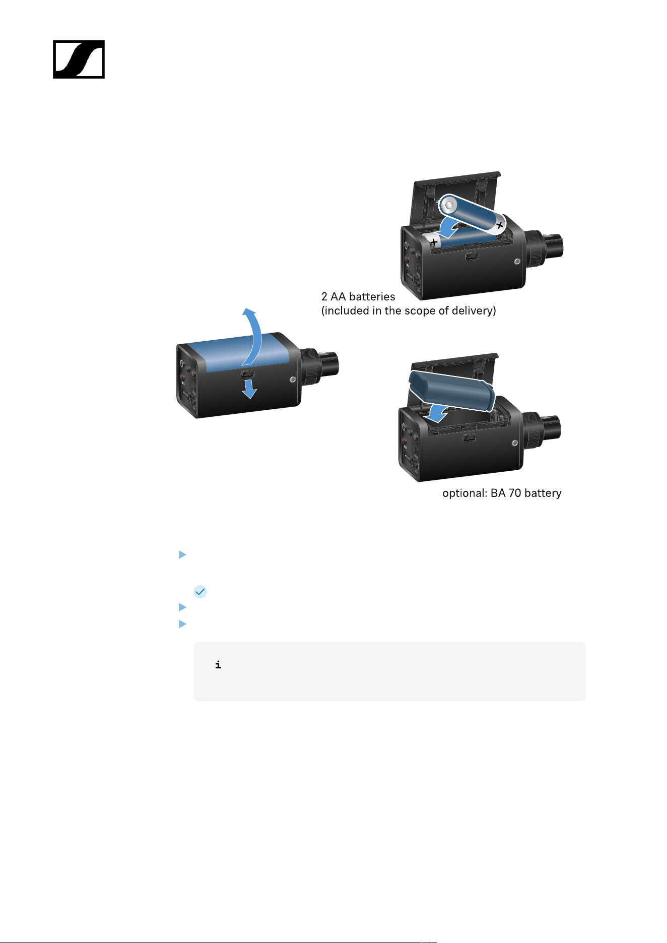
| 3 - Instruction manual
Power supply
Open the battery compartment of the EW-DP SKP by pulling down the release button
and gently pulling the lid toward the release button.
You can now open the battery compartment.
Insert either 2 AA batteries or a BA 70 rechargeable battery.
Close the battery compartment.
Removing the batteries or rechargeable battery while recording may
result in a corrupted recording file.
472

| 3 - Instruction manual
If stored for a long time without recharging or trickle charging, the
BA 70 battery may become deep-discharged. We therefore recommend
recharging the BA 70 battery after use and using trickle charging if stored
for a long time.
A deep-discharged BA 70 battery can be restored using the L 70 USB
charger (article no. 508861, available separately) and then used again
normally.
473
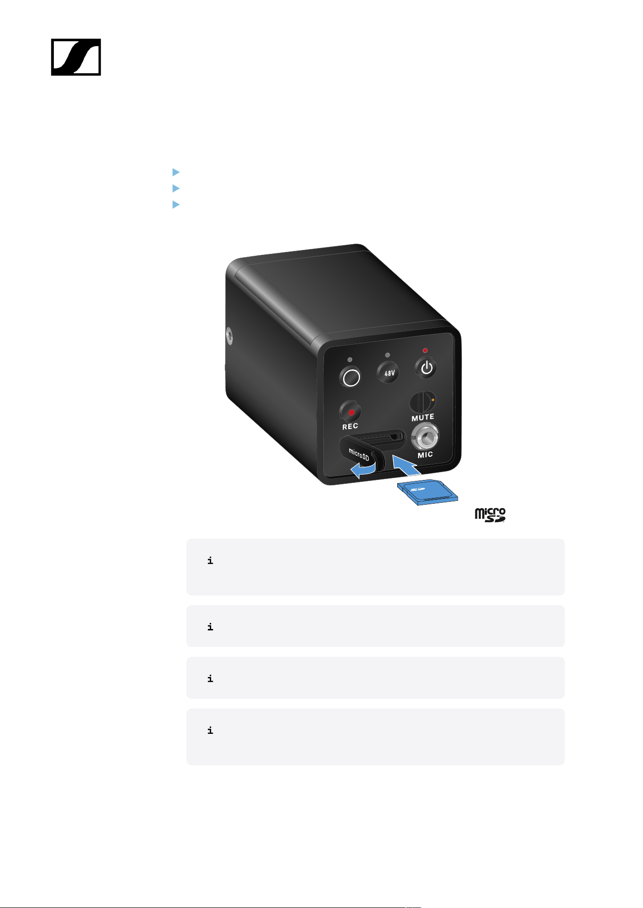
| 3 - Instruction manual
Using a microSD card
To insert a microSD card:
Open the rubber lip above the card slot.
Insert the microSD card.
Close the rubber lip again.
Removing the microSD card while recording is ongoing can result in a
destroyed recording file.
The EW-DP SKP supports the exFAT format.
Only microSD cards with a capacity of ≤ 1TB are supported.
We recommend formatting microSD cards in SKP before using them (for
the first time).
474

| 3 - Instruction manual
To format the microSD card:
Press the REC button for approx. 10 seconds.
The REC LED flashes slowly during formatting.
Ejecting the microSD card during an audio recording can destroy the
current recording file, all existing recording files, the file system or even
the entire microSD card.
Recommended microSD cards:
• SanDisk Ultra 128GB Class 10 U1 (and other GBs/speeds)
• SanDisk Extreme 128GB A2, C10, V30, U3 (and other GBs/speeds)
• SanDisk Extreme Pro 64GB A2, U3 V30
• SanDisk Extreme Pro 128GB A2, U3 V30
• Samsung 128GB evo select UHS-I U3
• Samsung 256GB evo select U3
• Intenso 64GB 10
• Lexar 128GB U3, A1, V30
• Lexar 64GB U3, A1, V30
• Lexar 32GB 633x V10b
• Verbatim per 64GB V30 U3 C10
• Transcend 64GB A1 U1 C10
475
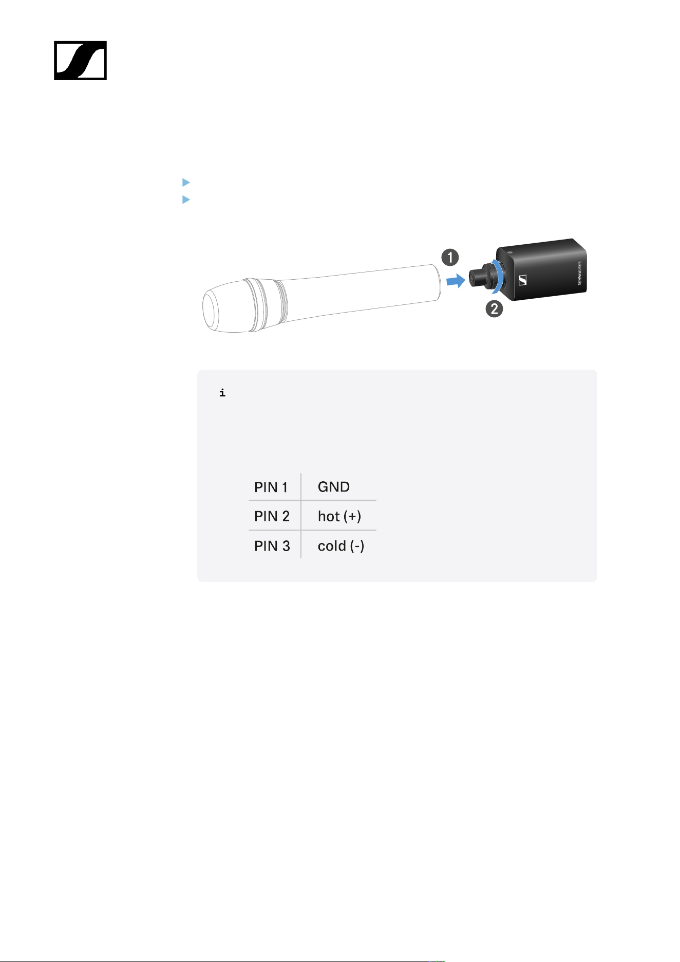
| 3 - Instruction manual
Attaching an XLR microphone
To attach an XLR microphone to the EW-DP SKP:
Connect the XLR microphone to the XLR connector of the plug-on transmitter.
Secure the microphone using the knurled screw.
The EW-DP SKP features an unbalanced input.
If the microphone you are using isn't working, please check whether it
uses a different pin configuration. In this case, we recommend using a
polarity reverser.
Pin assignment:
476
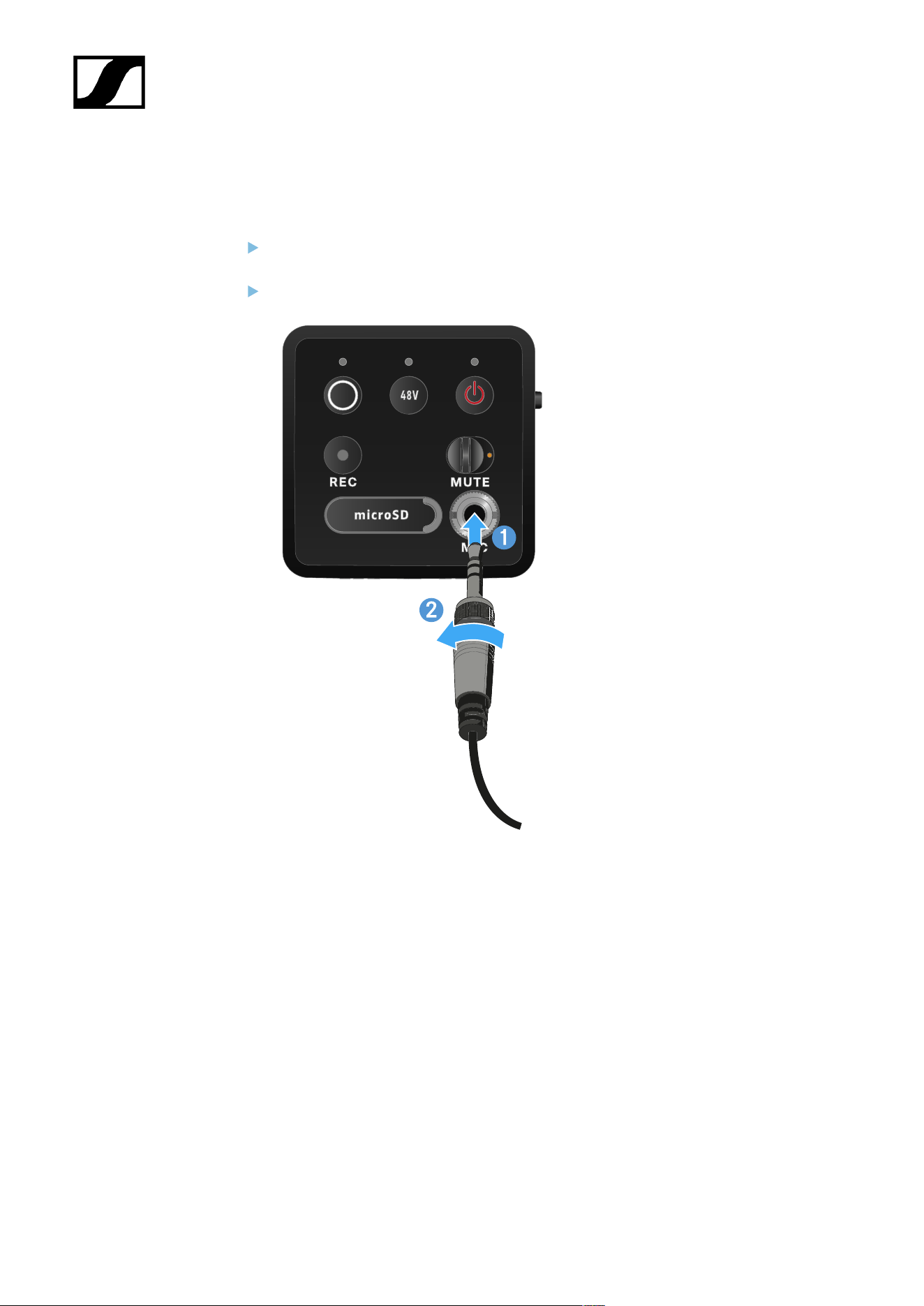
| 3 - Instruction manual
Connecting a lavalier microphone
To connect a lavalier microphone to the EW-DP SKP plug-on transmitter:
Insert the cable’s 3.5 mm jack plug into the socket on the plug-on transmitter as
shown in the diagram.
Screw the plug’s coupling ring onto the audio socket thread of the plug-on transmitter.
477
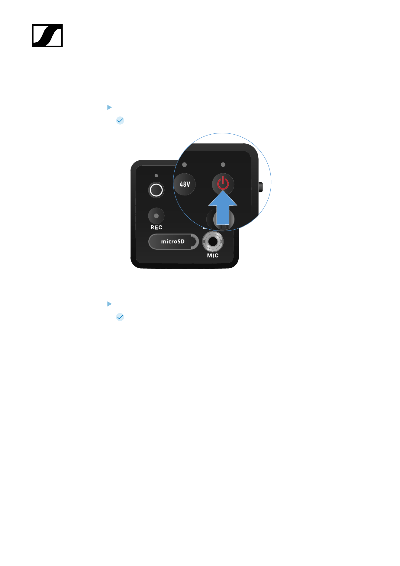
| 3 - Instruction manual
Switching the plug-on transmitter on and off
To switch the plug-on transmitter on:
Short-press the ON/OFF button.
The plug-on transmitter switches on.
To switch the plug-on transmitter off:
Press the ON/OFF button.
The plug-on transmitter switches off.
478
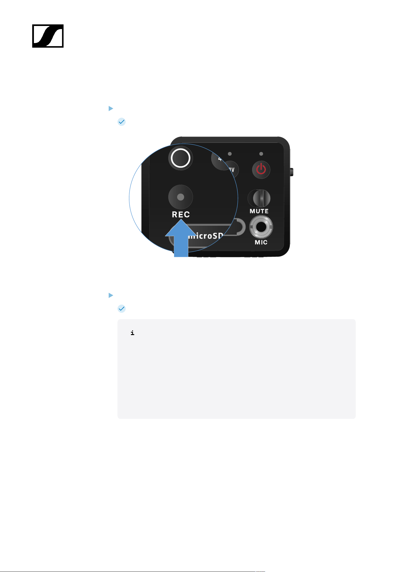
| 3 - Instruction manual
Starting/stopping recording
To switch the plug-on transmitter off:
Press the REC button briefly for one second.
Recording starts.
To stop recording:
Press the REC button briefly for one second.
Recording stops.
Due to the large 134 dB dynamic range of the EW-DP SKP, the *.wav audio
file recorded on the microSD card is very quiet.
• It may therefore be necessary to “normalize” the recording file
with an appropriate software tool before using it.
• We recommend increasing the audio level of the entire audio
recording to the maximum peak within the recording file.
• Instructions on how to do this are usually provided by the
manufacturers of these software tools (e.g. the free software
“Audacity”).
479

| 3 - Instruction manual
Activating/deactivating the low-cut filter
The low-cut filter reduces or removes low frequencies in the audio signal while allowing
high frequencies to pass through. This allows low-frequency ambient noise to be filtered
out of the audio signal, thereby improving the clarity of the recording.
The low-cut function of the EW-DP SKP comes activated on delivery and can
only be accessed via the Sennheiser Smart Assist app, which is available for
both Android and iPhone (see Smart Assist app). The EW-DP SKP remembers
the settings you make in the Smart Assist app and retains them even after it is
switched off/on.
To activate/deactivate the low-cut filter:
Pair your EW-DP SKP with the app.
You can find the low-cut function under the “Audio Link Controls” menu.
Select the frequency at which you want the filter to start, or activate/deactivate it.
The low-cut filter is now activated/deactivated.
480
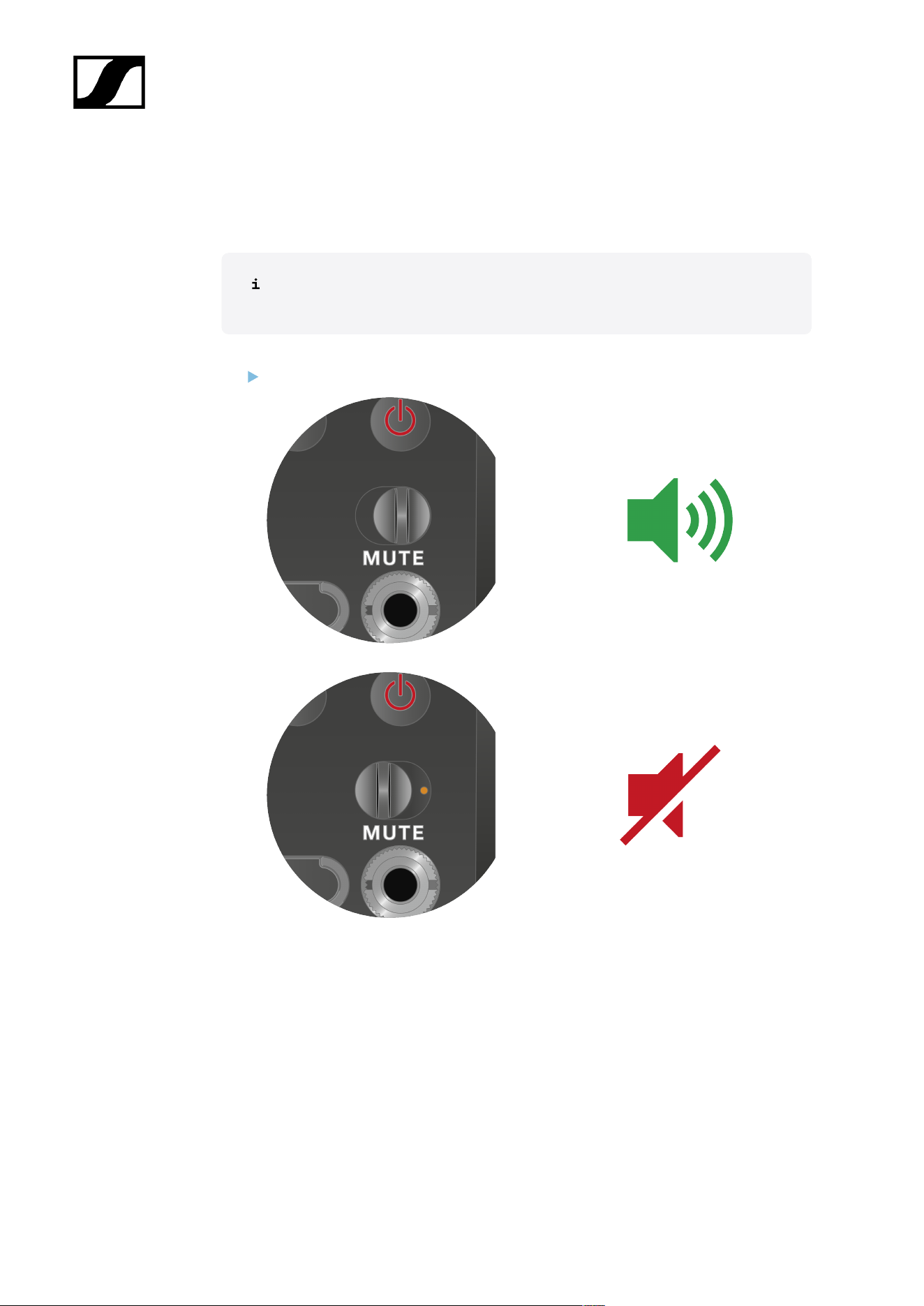
| 3 - Instruction manual
MUTE mode
You can mute the plug-on transmitter by turning off the audio signal using the MUTE switch.
Note: If you activate the MUTE switch while recording, the recording continues
and is not muted, even though the MUTE switch was activated.
Slide the MUTE switch to the desired position to mute or activate the audio signal.
481
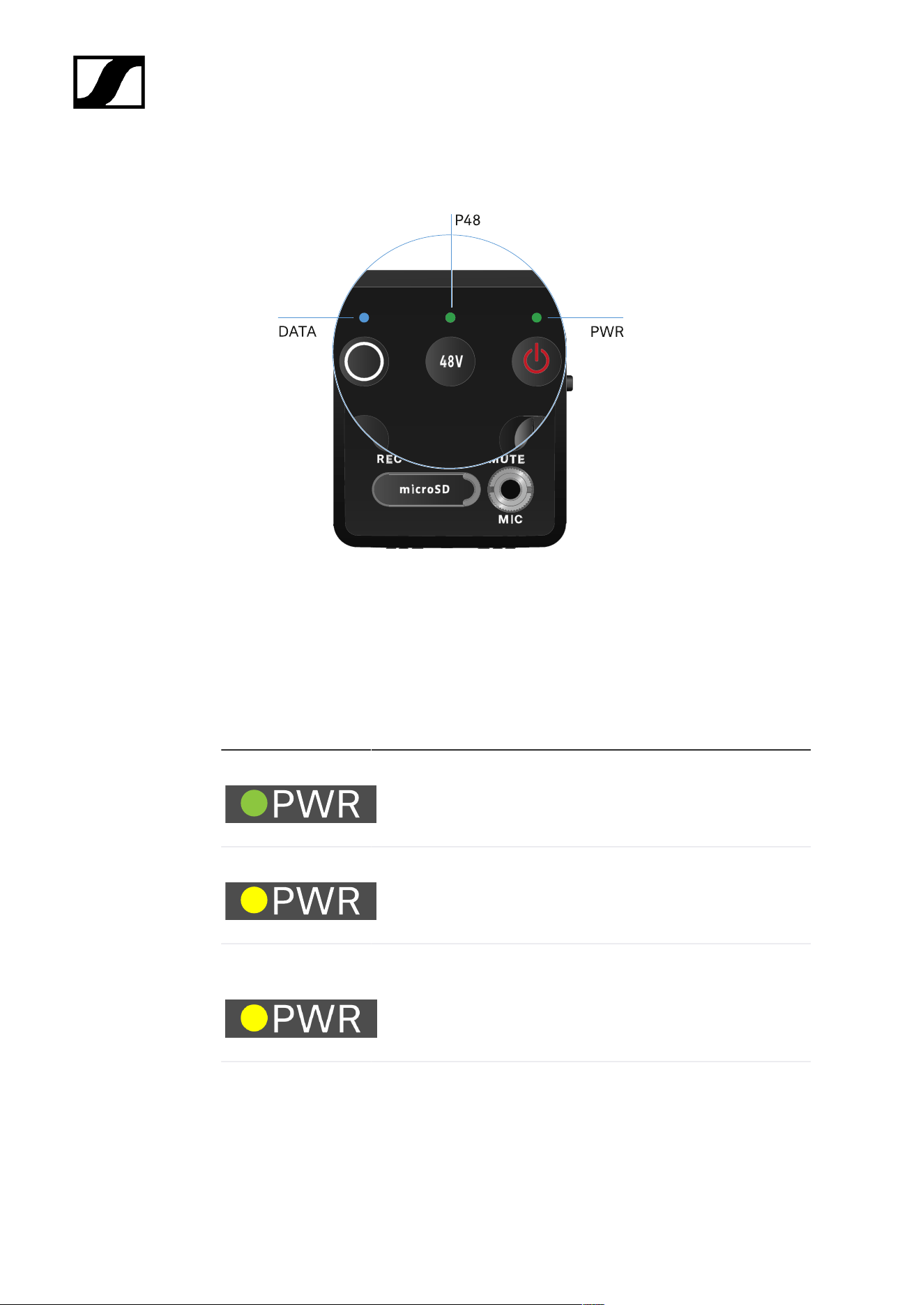
| 3 - Instruction manual
Meaning of the LEDs
The LINK, DATA and POWER LEDs on the front of the receiver can indicate the following
information.
PWR LED
The PWR LED provides information about the status of the radio link between the transmitter
and receiver, as well as status information about the battery charge.
The LED is green:
• The link between the transmitter and receiver is established.
• The audio signal is active.
The LED is yellow:
• The link between the transmitter and receiver is established.
• The audio signal is muted.
The LED is flashing
yellow:
• The link between the transmitter and receiver is established.
• The audio signal is overdriven (clipping).
The LED is
continuously red:
• No link between the transmitter and receiver.
482
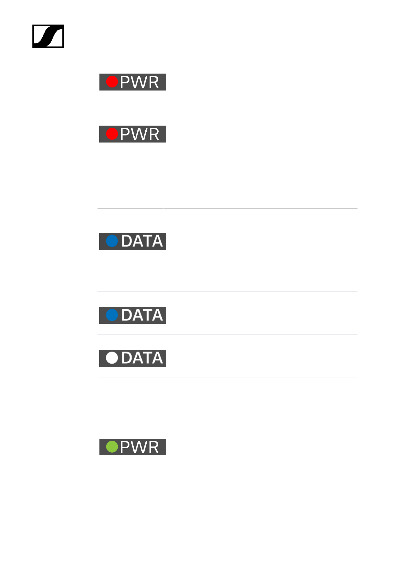
| 3 - Instruction manual
The LED is flashing
red:
• The battery/rechargeable battery is low.
DATA LED
The DATA LED provides information on the receiver’s Bluetooth Low Energy link to the
Smart Assist app and on the synchronization of transmitters and receivers.
The LED is flashing
blue:
• The Bluetooth Low Energy link is being established
between the receiver and a smartphone or tablet with the
Smart Assist app.
or
• The receiver is being synchronized with a transmitter.
The LED is blue:
• The firmware is being updated.
The LED is off:
• Normal operation
• There is currently no active data link.
P48 LED
The P48 LED indicates whether phantom power P48 is activated.
The LED is green:
• phantom power P48 is active.
RECORDING LED
The RECORDING LED indicates the status of the recording or a possible malfunction.
483
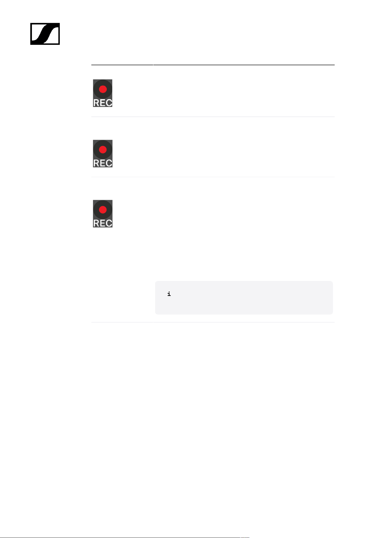
| 3 - Instruction manual
The LED remains lit:
• Recording is active.
The LED flashes
slowly:
• Action is in progress, such as formatting the memory card.
The LED flashes
rapidly:
• Error. There are several possible reasons why an error would
be displayed:
• Memory card not inserted or faulty
• A current recording has less than 10 minutes (= ~81
MB of disk space) of time remaining
• Less than 3 minutes (= ~24 MB of disk space) of
recording time remaining when starting a new
recording (recording stops)
• Write error
• Buffer exceeded
We recommend fully formatting the memory card using
your PC (do not select “Quick format”).
484
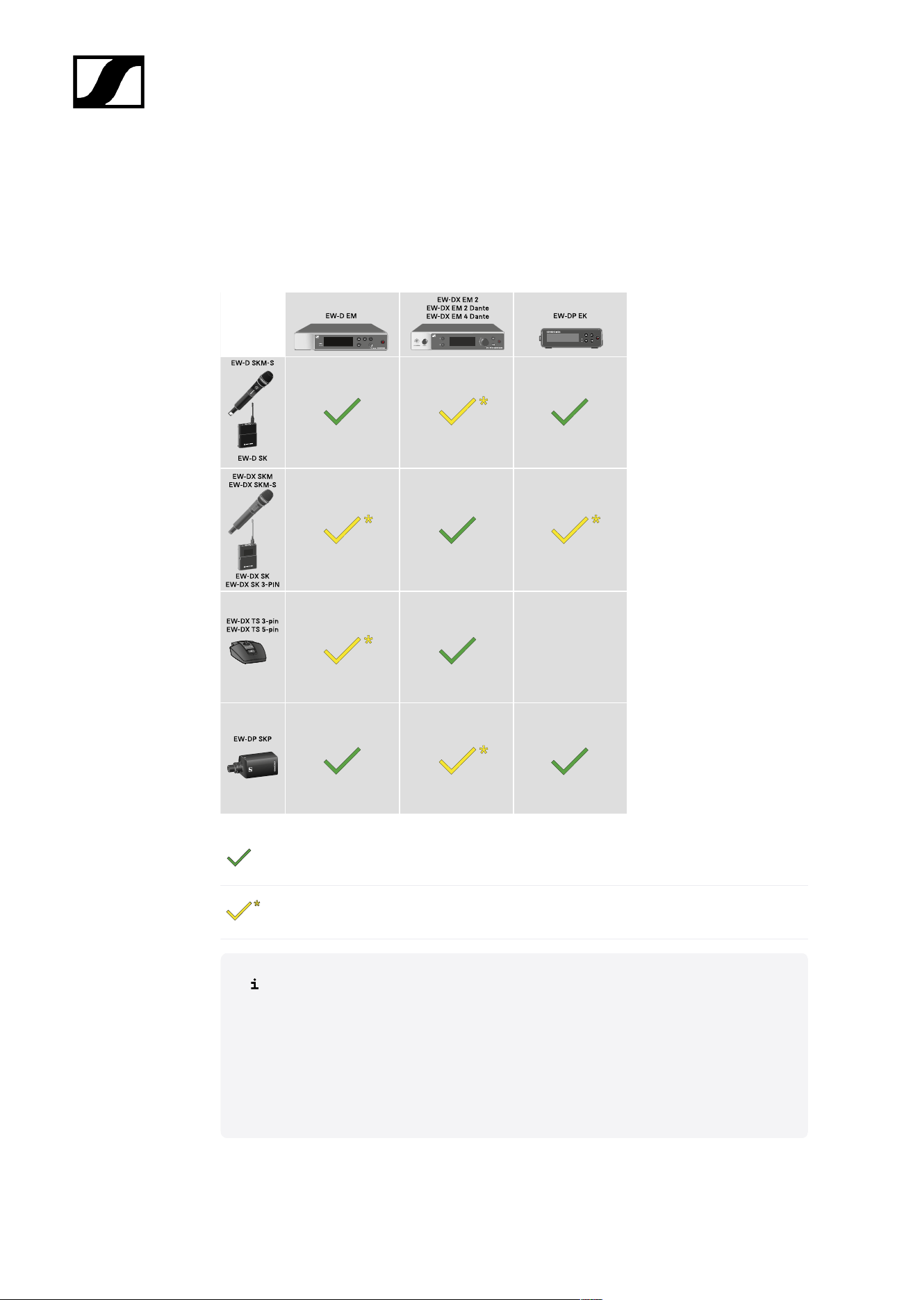
| 3 - Instruction manual
Establishing a radio link | Synchronizing the receiver
and transmitter
Information on compatibility between EW-D, EW-DX and EW-DP
The transmitter and the receiver are fully compatible with each other.
The transmitter and the receiver are compatible with each other. Some features may
not be available.
Conditions and restrictions for using frequencies
There may be special conditions and restrictions for using frequencies in your
country.
Before putting the product into operation, find the information for your country
at the following address:
sennheiser.com/sifa
485
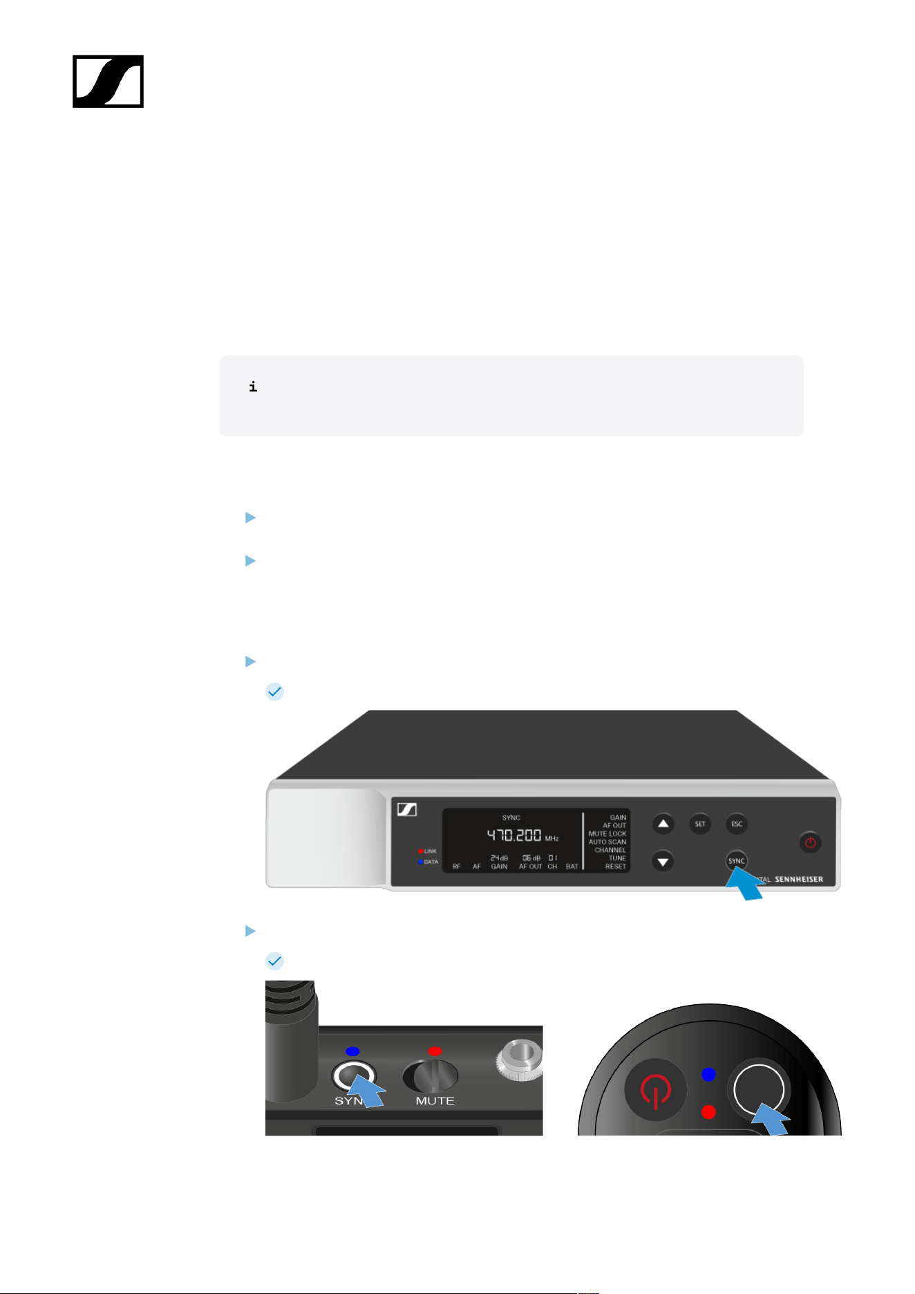
| 3 - Instruction manual
Connecting to the EW-D EM receiver / synchronizing the EW-D
EM
To establish a radio link between the transmitter and receiver, we recommend the following
procedure.
In order to establish a connection between a receiver and transmitters of the EW-D series,
the devices must always be synchronized with each other.
To successfully connect a receiver and a transmitter, both devices must have the
same frequency range.
Step 1: Set a free frequency
We recommend using the AUTO SCAN function, as this is the most reliable way to
identify free frequencies (see AUTO SCAN menu item).
If you know free frequencies in your area, you can also set the frequency manually
(see CHANNEL menu item or TUNE menu item).
Step 2: Pairing a receiver with a transmitter
Short-press the SYNC button on the receiver.
The blue DATA LED flashes.
Short-press the SYNC button on the transmitter.
The blue DATA LED flashes.
486

| 3 - Instruction manual
The transmitter and receiver will be paired. Once the link is established, the LINK
LED on both units will light up green.
Be sure to press the SYNC button on all devices only briefly (less than 2 seconds).
Holding the SYNC button longer than this will start the firmware update mode
and cancel the synchronization process.
487
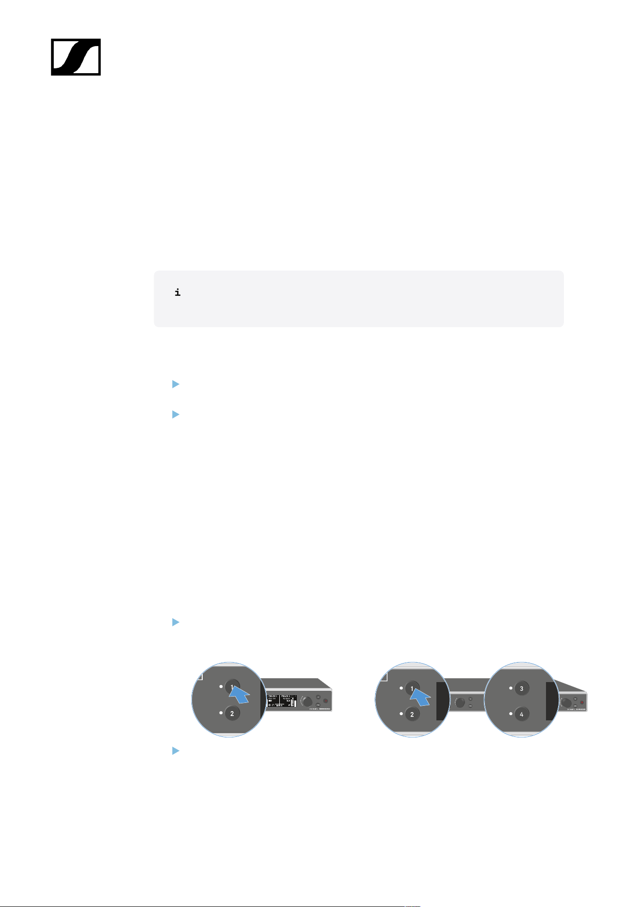
| 3 - Instruction manual
Connecting to the EW-DX EM receivers / synchronizing the EW-
DX EM
Receiver: EW-DX EM 2 | EW-DX EM 2 Dante | EW-DX EM 4 Dante
To establish a radio link between the transmitter and receiver, we recommend the following
procedure.
In order to establish a connection between a receiver and transmitters of the EW-D series,
the devices do not necessarily have to be synchronized with each other.
To successfully connect a receiver and a transmitter, both devices must have the
same frequency range.
Step 1: Set a free frequency
We recommend using the AUTO SCAN function, as this is the most reliable way to
identify free frequencies (see Ch 1 / Ch 2 -> Scan / Auto Setup menu item).
If you know free frequencies in your area, you can also set the frequency manually.
• EW-DX EM 2: Ch 1 / Ch 2 -> Frequency menu item
• EW-DX EM 2 Dante: Ch 1 / Ch 2 -> Frequency menu item
• EW-DX EM 4 Dante: Ch 1 - Ch 4 -> Frequency menu item
• EW-DX SKM(-S): Opening the menu and navigating the menu items
• EW-DX SK (3-PIN): Opening the menu and navigating the menu items
Once you have set the same frequency for the desired receiving channel on the
receiver and for the transmitter you want to connect, the radio link is established.
To ensure that all settings are transmitted to the transmitter, we recommend
synchronizing the transmitter with the receiving channel.
Step 2: Synchronizing the receiver and transmitter
On the EW-DX EM 2 and EW-DX EM 2 Dante receivers, press the CH 1
or CH 2 button, and on the EW-DX EM 4 Dante receiver, press the CH
1, CH 2, CH 3 or CH 4 button to select the channel for synchronization.
Press the SYNC button on the receiver.
488
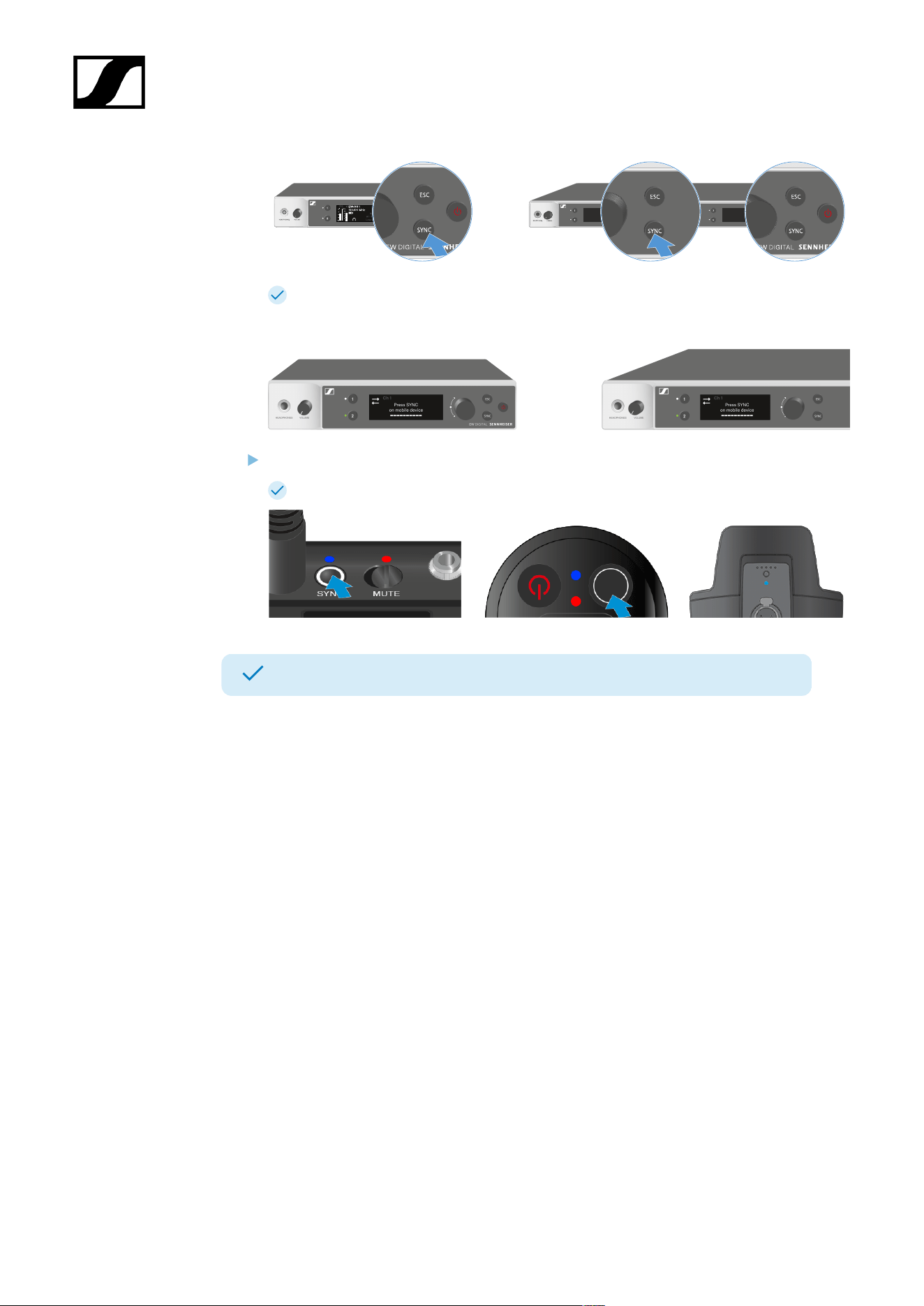
| 3 - Instruction manual
The receiver’s display shows that the synchronization process has started.
The blue DATA LED flashes.
Short-press the SYNC button on the transmitter.
The blue DATA LED flashes.
The transmitter and receiver will be synchronized.
489
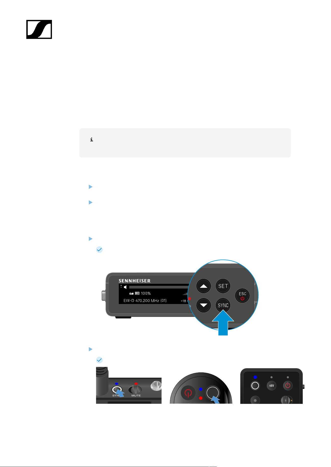
| 3 - Instruction manual
Connecting to the EW-DP EK receiver / synchronizing the EW-DP
EK
To establish a radio link between the transmitter and receiver, we recommend the following
procedure.
In order to establish a connection between a receiver and transmitters of the EW-DP EK
series, the devices must always be synchronized with each other.
To successfully connect receivers and transmitters, both devices must have the
same frequency range.
Step 1: Set a free frequency
We recommend using the AUTO SCAN function, as this is the most reliable way to
identify free frequencies (see AUTO SCAN menu item).
If you know free frequencies in your area, you can also set the frequency manually
(see CHANNEL menu item or FREQUENCY menu item).
Step 2: Pairing a receiver with a transmitter
Short-press the SYNC button on the receiver.
The blue DATA LED flashes.
Short-press the SYNC button on the transmitter.
The blue DATA LED flashes.
490

| 3 - Instruction manual
The transmitter and receiver will be paired. Once the link is established, the LINK
LED on both units will light up green.
Be sure to press the SYNC button on all devices only briefly (less than 2 seconds).
Holding the SYNC button longer than this will start the firmware update mode
and cancel the synchronization process.
491
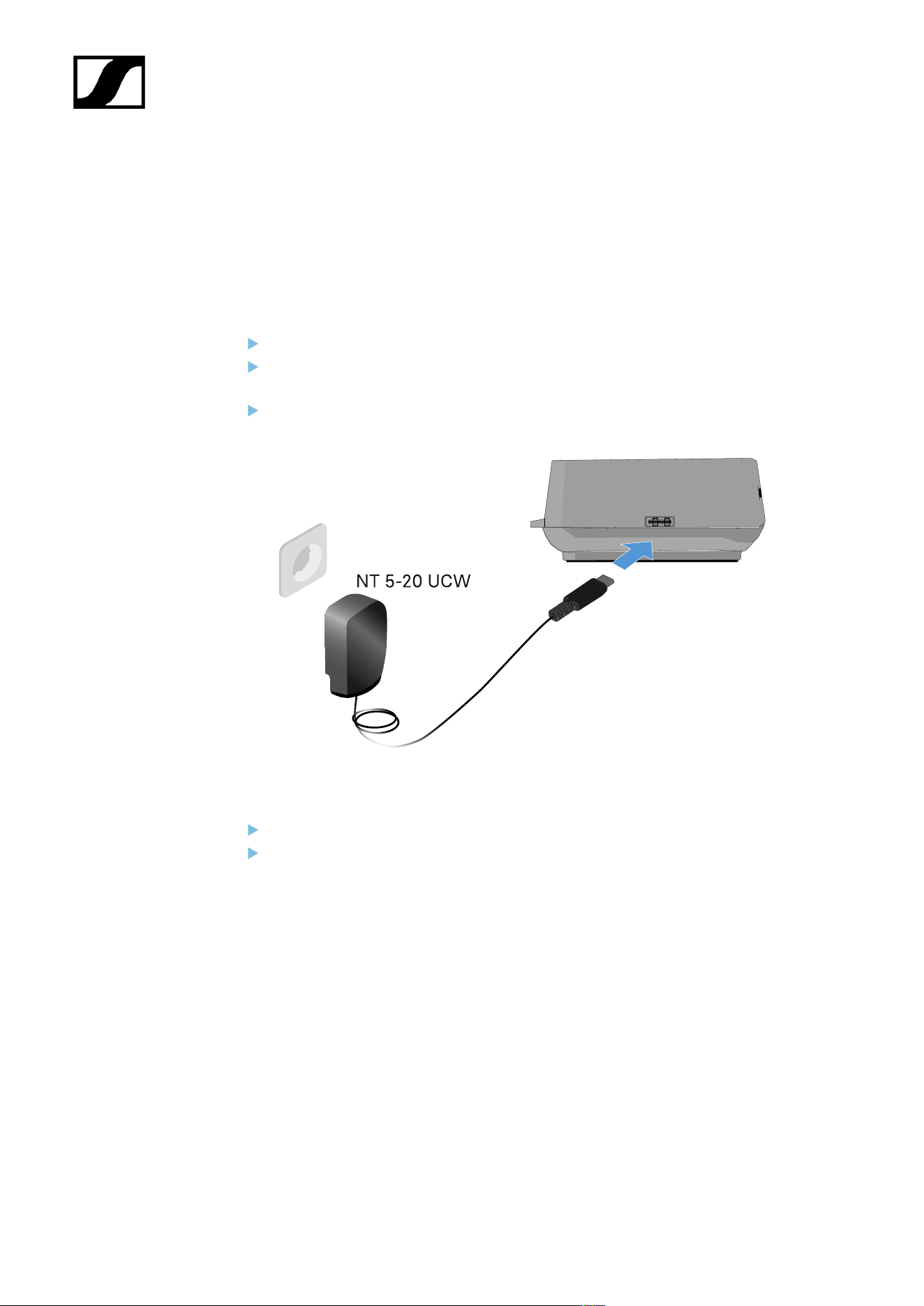
| 3 - Instruction manual
L 70 USB charger
Connecting/disconnecting the charger to/from the power supply
system
To connect the charger to the power supply system:
Use only the NT 5-20 UCW power supply unit from Sennheiser.
Connect the USB-C plug on the charging cable to the USB-C port on the side of the
charger.
Plug the power supply unit with the correct country adapter into a suitable power
outlet.
To disconnect the charger from the power supply system:
Unplug the power supply unit from the wall socket.
Remove the USB-C plug on the charging cable from the USB-C port on the side of the
charger.
492
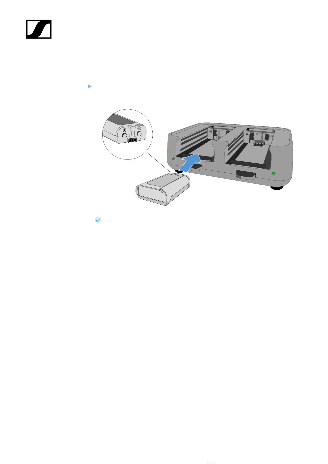
| 3 - Instruction manual
Charging the rechargeable battery
To charge the BA 70 rechargeable battery in the L 70 USB charger:
Slide the rechargeable battery completely into the charging slot as shown in the
figure.
The rechargeable battery will begin charging.
The LED on the charging slot shows the battery’s charge level:
493
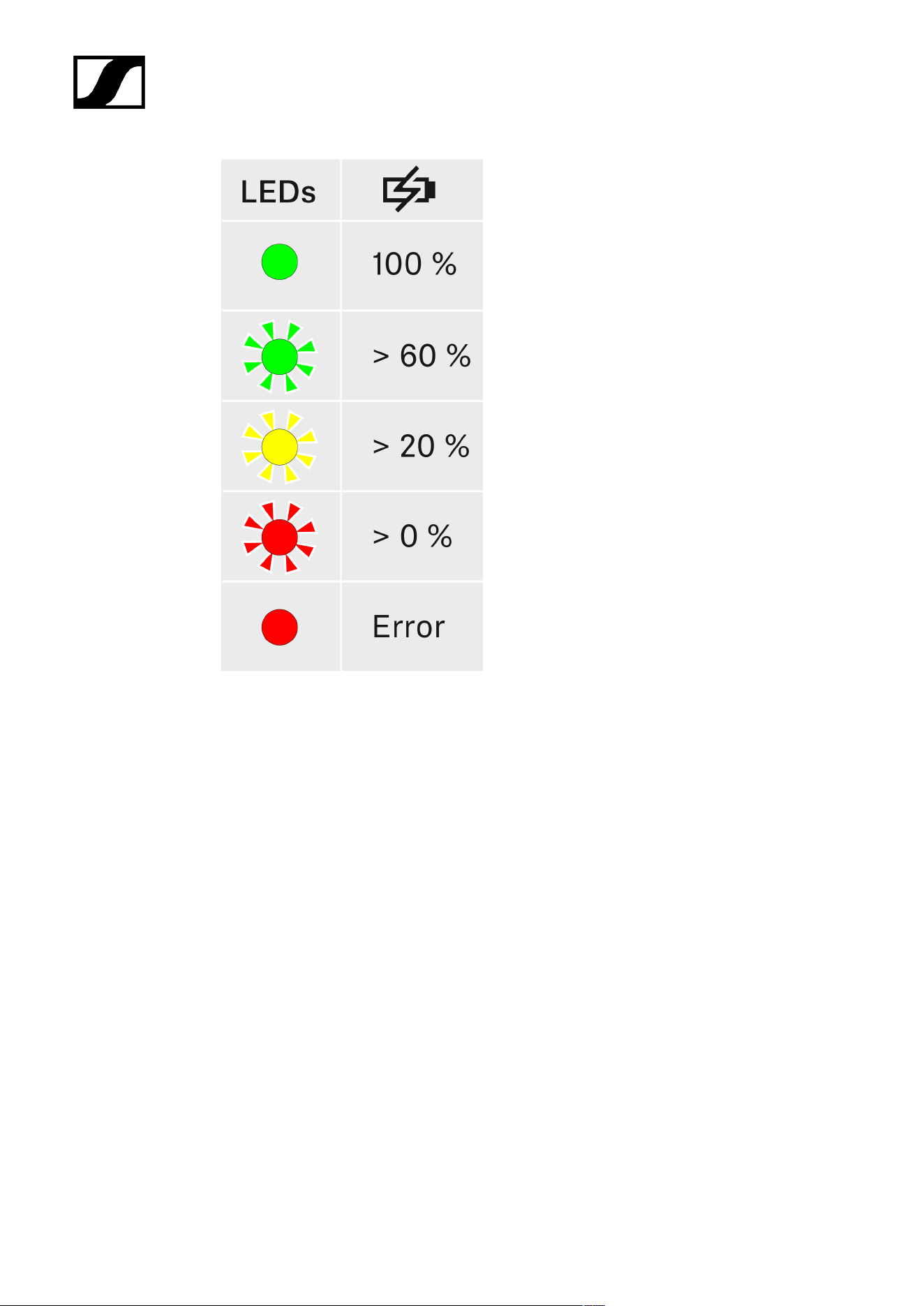
| 3 - Instruction manual
494
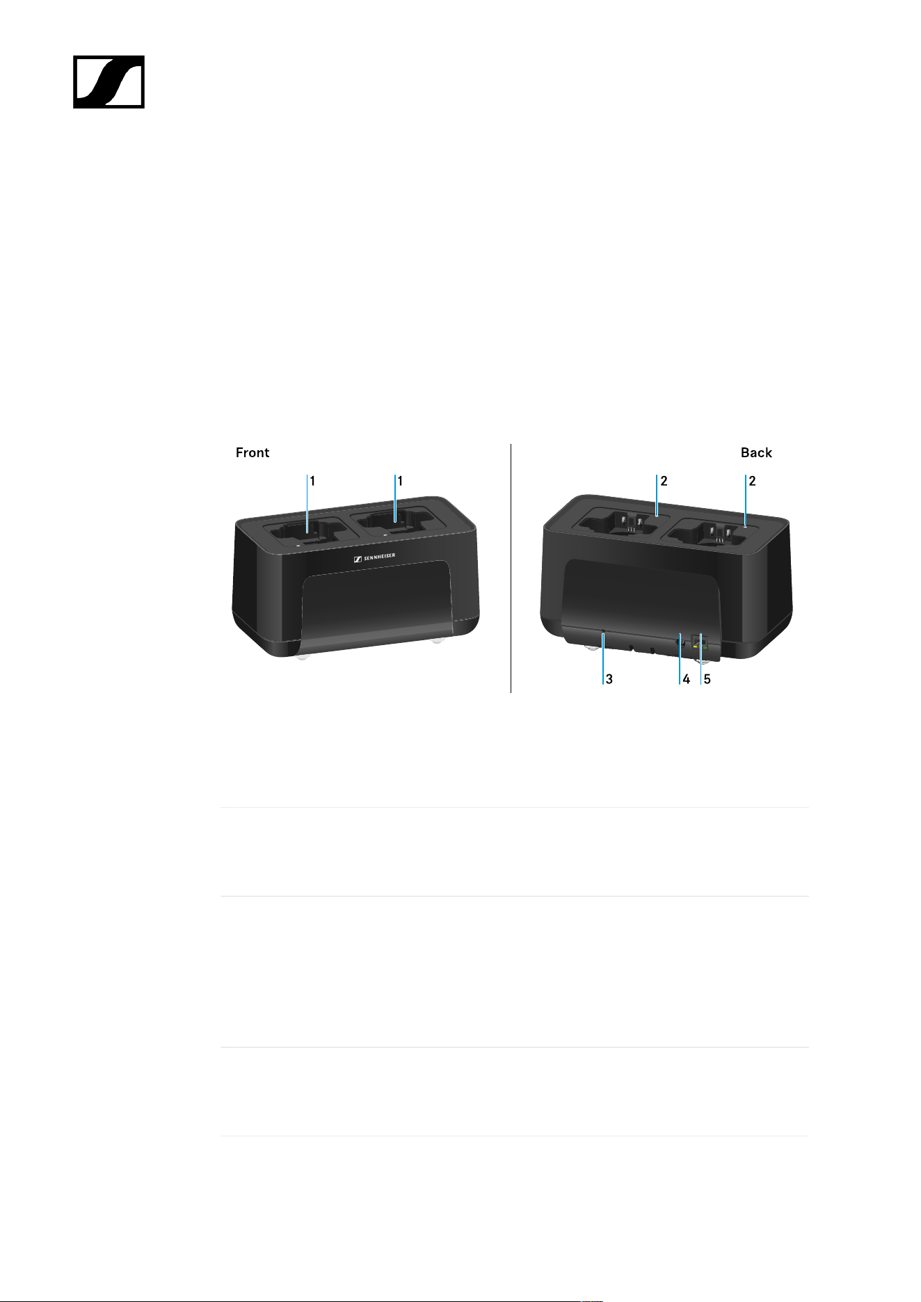
| 3 - Instruction manual
CHG 70N-C charger
The CHG 70N-C is a network enabled charger featuring two individual charging bays.
Compatible products:
• EW-DX SKM/EW-DX SKM-S handheld transmitter
• EW-DX SK/EW-DX SK 3-PIN bodypack transmitter
• SPECTERA SEK bidirectional transmitter
• BA 70 rechargeable battery
Product overview
1 Charging slots
• See Charging the rechargeable battery
2 Status LED of the charging slots
• See Charging the rechargeable battery
3 Reset button
• Press and hold for 10 seconds to reset the device’s network settings, see
Connecting a charger in a network
• Press and hold for 4 seconds to enable power saving mode, see Power saving
mode
4 DC in connection socket for the NT 12-35 CS power supply unit
• See Connecting/disconnecting the charger to/from the power supply system
495

| 3 - Instruction manual
5 PoE/Ethernet RJ45 socket for controlling the device over the network and for Power over
Ethernet power supply
• See Connecting a charger in a network
• See Connecting/disconnecting the charger to/from the power supply system
You can cascade up to 5 devices with only one power supply and one network
connection. See Cascading chargers.
496
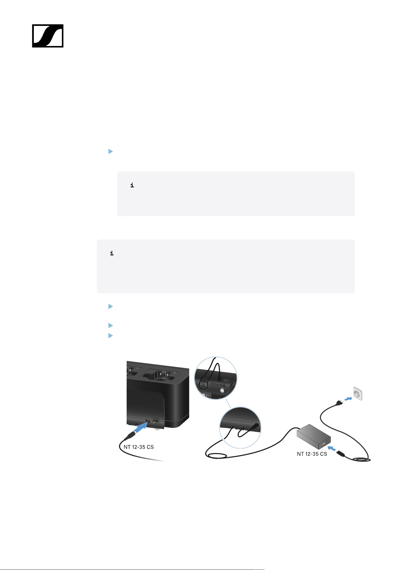
| 3 - Instruction manual
Connecting/disconnecting the charger to/from the power supply
system
You can operate the charger either with the Sennheiser NT 12-35 CS power supply unit
or with Power over Ethernet (PoE IEEE 802.3af Class 0). Please refer to the following
information.
Power from the NT 12-35 CS power supply unit
Use only the NT 12-35 CS power supply unit from Sennheiser. It is designed for your
charger and ensures safe operation.
The power supply unit is available either separately (Sennheiser article
number 508995) or together with the charger as a kit (see CHG 70N-C
network-enabled charger).
Power from the NT 12-35 CS power supply unit
Use only the NT 12-35 CS power supply unit from Sennheiser. It is designed
for your charger and ensures safe operation. The power supply unit is available
either separately (Sennheiser article number 508995) or together with the
charger as a kit (see CHG 70N-C network-enabled charger).
Connect the hollow jack plug of the power supply unit to the DC in socket on the
charger.
Pass the cable through the strain relief.
Plug the power supply unit into the wall outlet using the correct power cable for your
country.
497
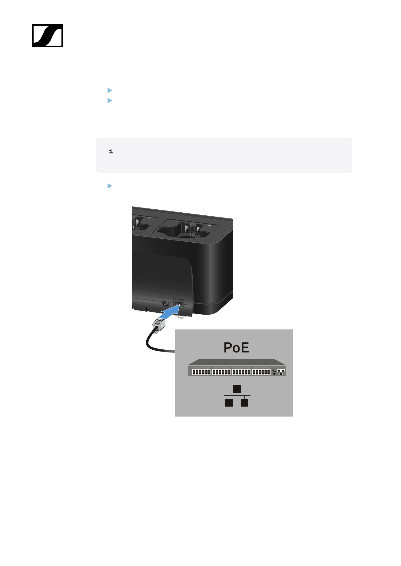
| 3 - Instruction manual
Disconnecting the charger completely from the power supply system
Unplug the mains cable from the wall socket.
Unplug the hollow jack plug of the power supply unit from the DC in socket on the
charger.
Power over Ethernet (PoE)
The charger can be powered via Power over Ethernet (PoE IEEE 802.3af Class
0).
Connect the charger to a PoE-enabled network switch.
498
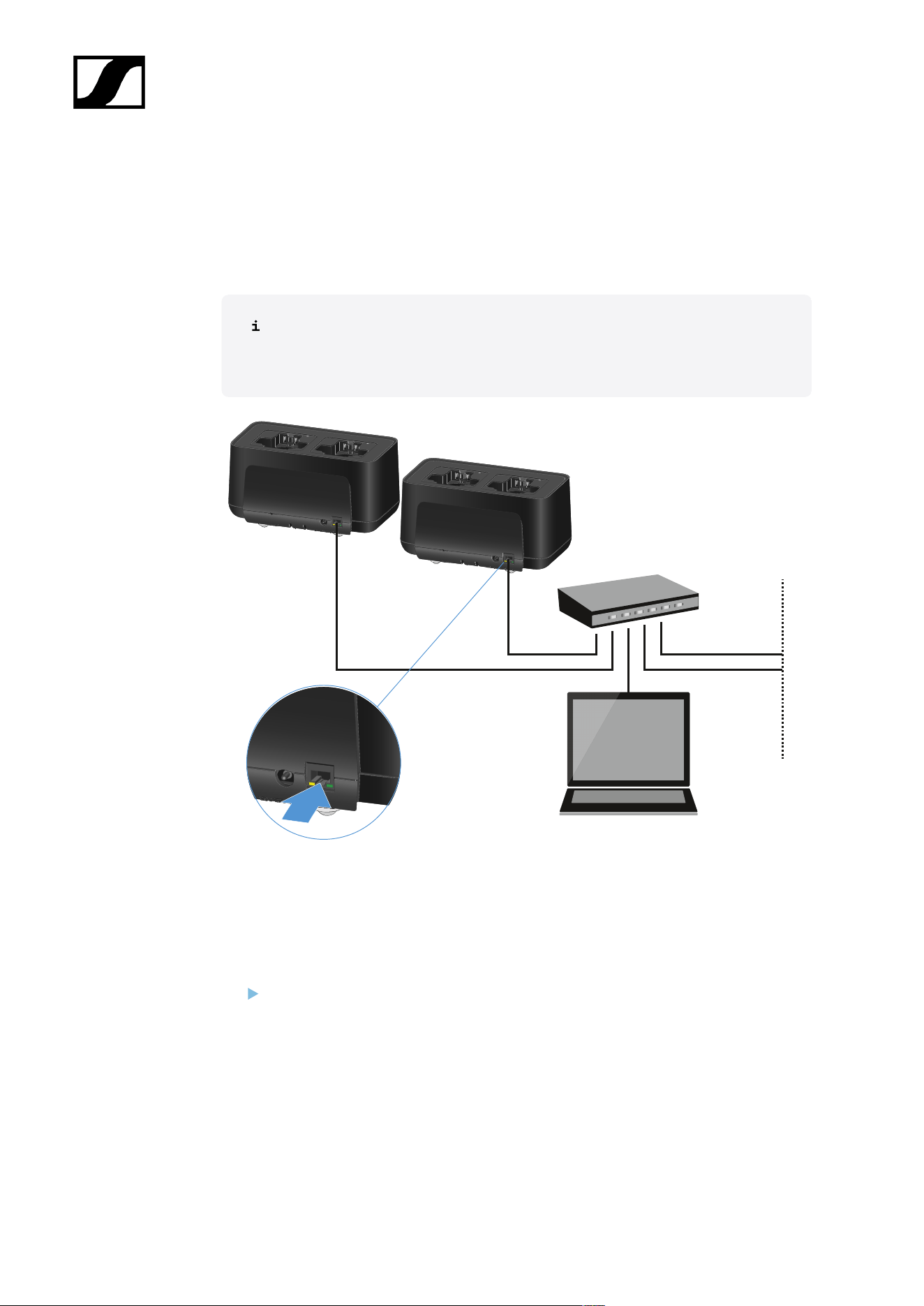
| 3 - Instruction manual
Connecting a charger in a network
You can monitor and control one or more chargers via a network connection using the
Sennheiser Wireless Systems Manager (WSM) or Sennheiser Control Cockpit (SCC)
software.
The network does not have to be a homogeneous network including only
chargers. You can integrate the charger into your existing network infrastructure
with any other types of devices.
You can integrate the devices into the network individually or cascade up to 5 chargers (see
Cascading chargers).
To reset the network settings to their factory defaults:
Hold the Reset button for 4 seconds.
499

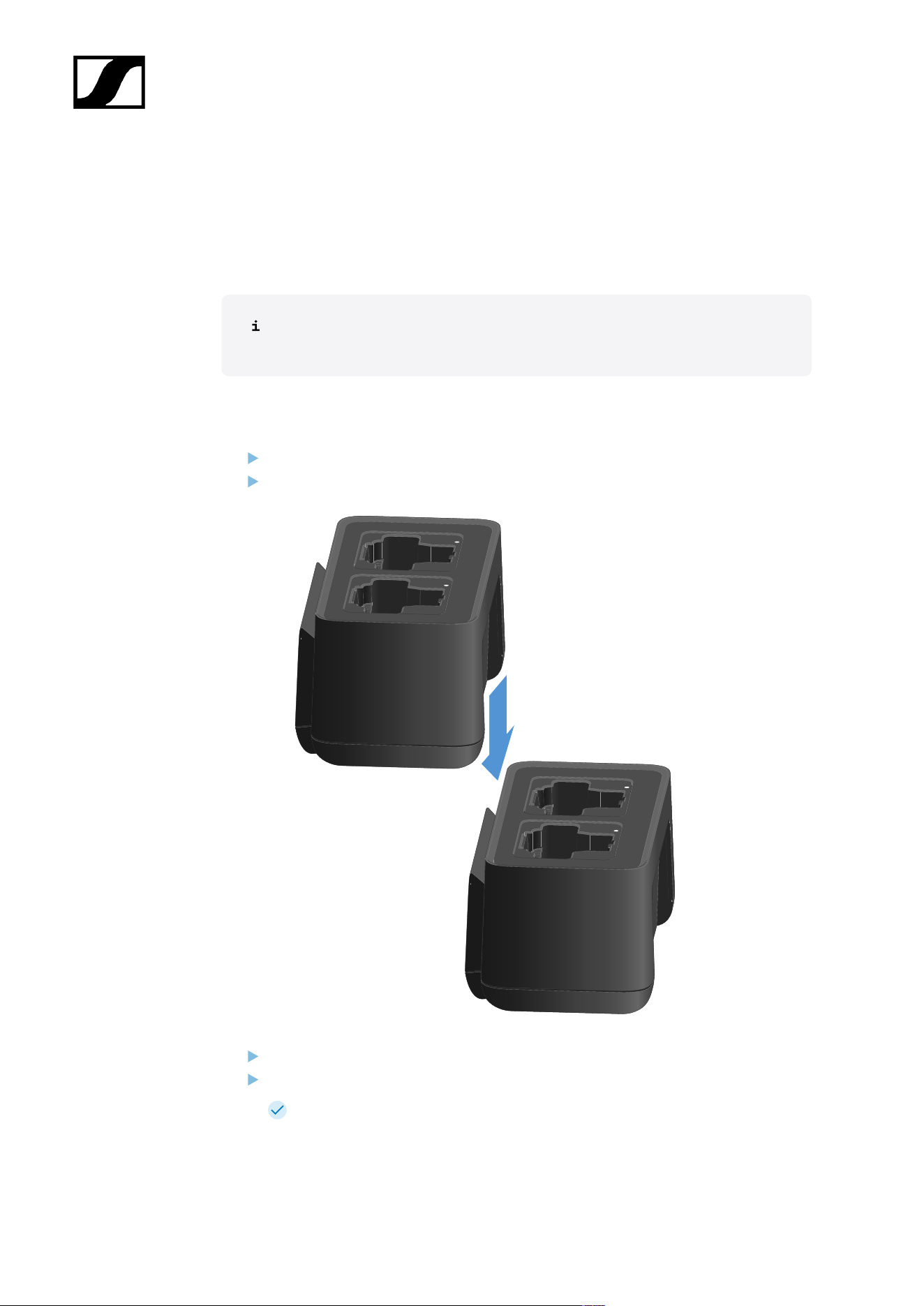
| 3 - Instruction manual
Cascading chargers
You can cascade up to five CHG 70N-C chargers and operate them with a single power
supply and a single network connection. This minimizes the cabling required for larger
systems.
The power must be supplied via the NT 12-35 CS power supply unit. Power over
Ethernet (PoE) is not possible when cascading.
To cascade the chargers:
Make sure that no chargers are connected to the power before you start.
Plug the chargers into each other as shown in the figure.
Detach the connecting rail on the bottom of the charger.
Fasten the connecting rail beneath two chargers as shown in the figure.
The power and the network connection are passed on to all devices via the
connecting rails.
501
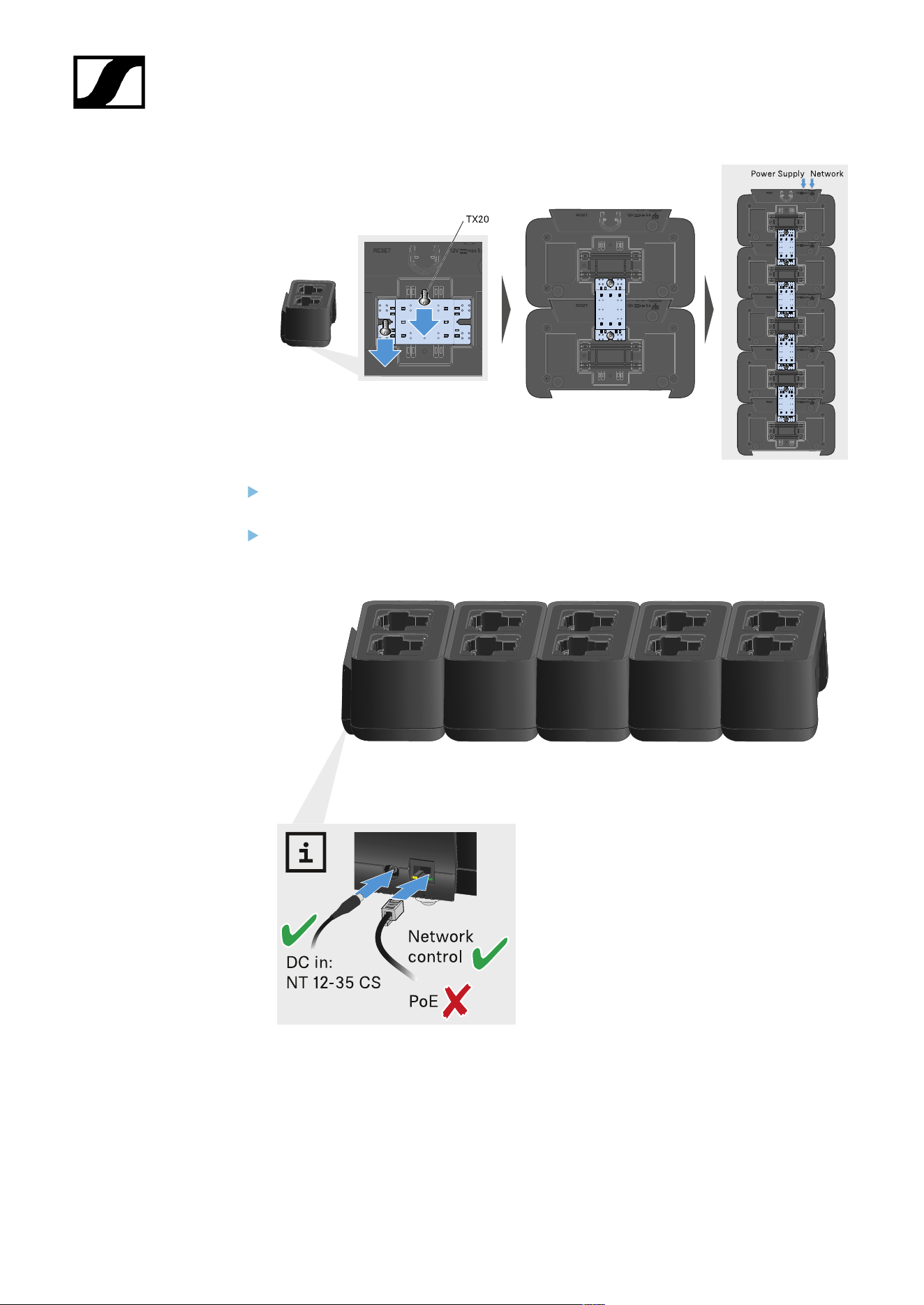
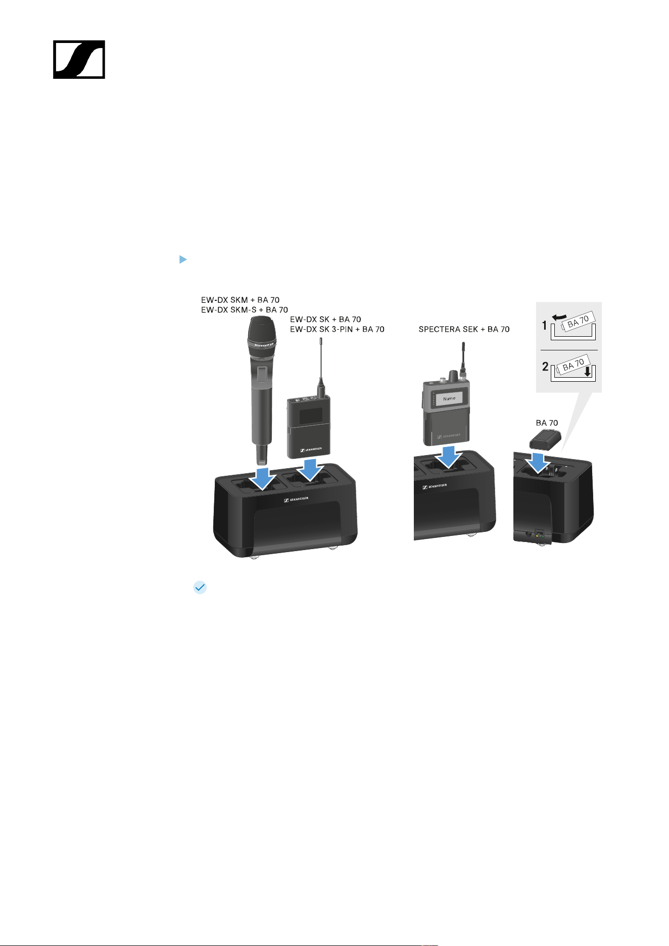
| 3 - Instruction manual
Charging the rechargeable battery
You can use the CHG 70N-C charger to charge individual BA 70 rechargeable batteries, or to
charge EW-DX SKM, EW-DX SKM-S, EW-DX SK, EW-DX SK 3-PIN or Spectera SEK with the
BA 70 rechargeable battery already inserted.
To charge the battery:
Insert the individual rechargeable battery or the transmitter with battery already
inserted into the charging slot as shown in the figure.
The rechargeable battery will begin charging.
The LED on the charging slot shows the battery’s charge level.
503

| 3 - Instruction manual
504

| 3 - Instruction manual
Power saving mode
In power saving mode, the transmitters are charged only once. The charger also does not
provide any trickle charge.
To activate power saving mode:
In power saving mode, the CHG 70N-C cannot be controlled over the network.
Remove all transmitters and/or rechargeable batteries from the charging slots.
Hold the Reset button for 4 seconds.
The charging slot LEDs light up purple.
Insert the rechargeable battery/transmitter for charging.
The rechargeable battery will begin charging. The charging slot LED turns green
once it reaches full charge.
To deactivate power saving mode:
Disconnect the charger from the power supply system.
Then reconnect it to the power supply system.
The charger will start up in the configuration that was set before you activated
power saving mode.
505
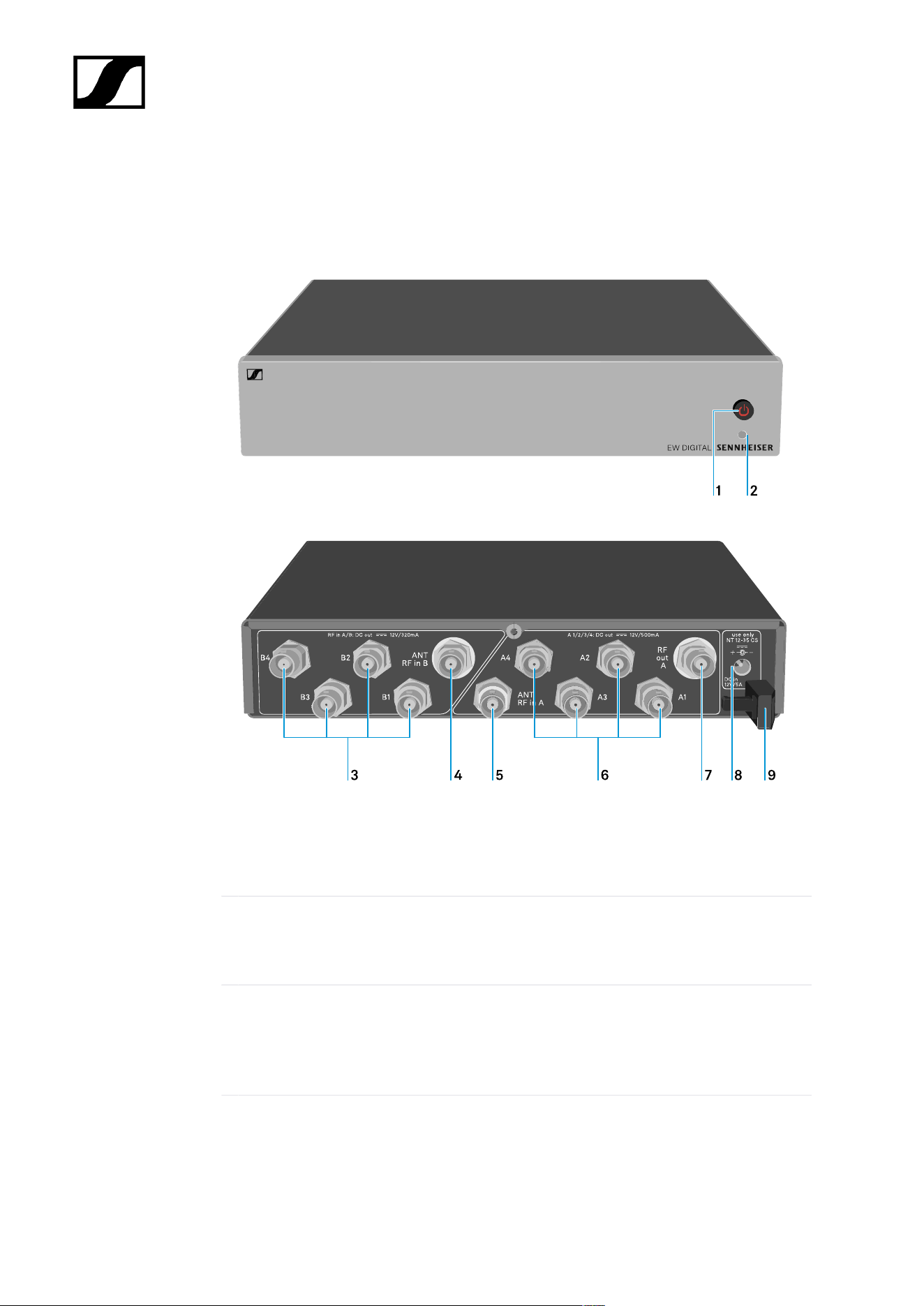
| 3 - Instruction manual
EW-D ASA antenna splitter
Product overview
1 STANDBY button
• See Switching the EW-D ASA on and off
2 LED: Operation indicator
• See Switching the EW-D ASA on and off
3 4 BNC sockets B1 to B4
• RF outputs of diversity branch B for connection to the receiver
• See Connecting receivers to the EW-D ASA
506

| 3 - Instruction manual
4 ANT RF IN B BNC socket
• Antenna input of diversity branch B
• See Connecting antennas
5 ANT RF IN A BNC socket
• Antenna input of diversity branch A
• See Connecting antennas
6 4 BNC sockets A1 to A4
• RF outputs of diversity branch A for connection to the receiver
• Each one of these RF outputs can also provide power to an EW-D EM receiver
• See Connecting receivers to the EW-D ASA
7 RF OUT A BNC socket
• RF output only for connecting an additional ASA 214 to build an 8-channel
diversity system
• See Configuring multi-channel systems
8 DC in socket
• To connect the NT 12-35 CS power supply unit
• See Connecting/disconnecting the EW-D ASA to/from the power supply system
9 Strain relief for the connection cable of the power supply unit
• See Connecting/disconnecting the EW-D ASA to/from the power supply system
507
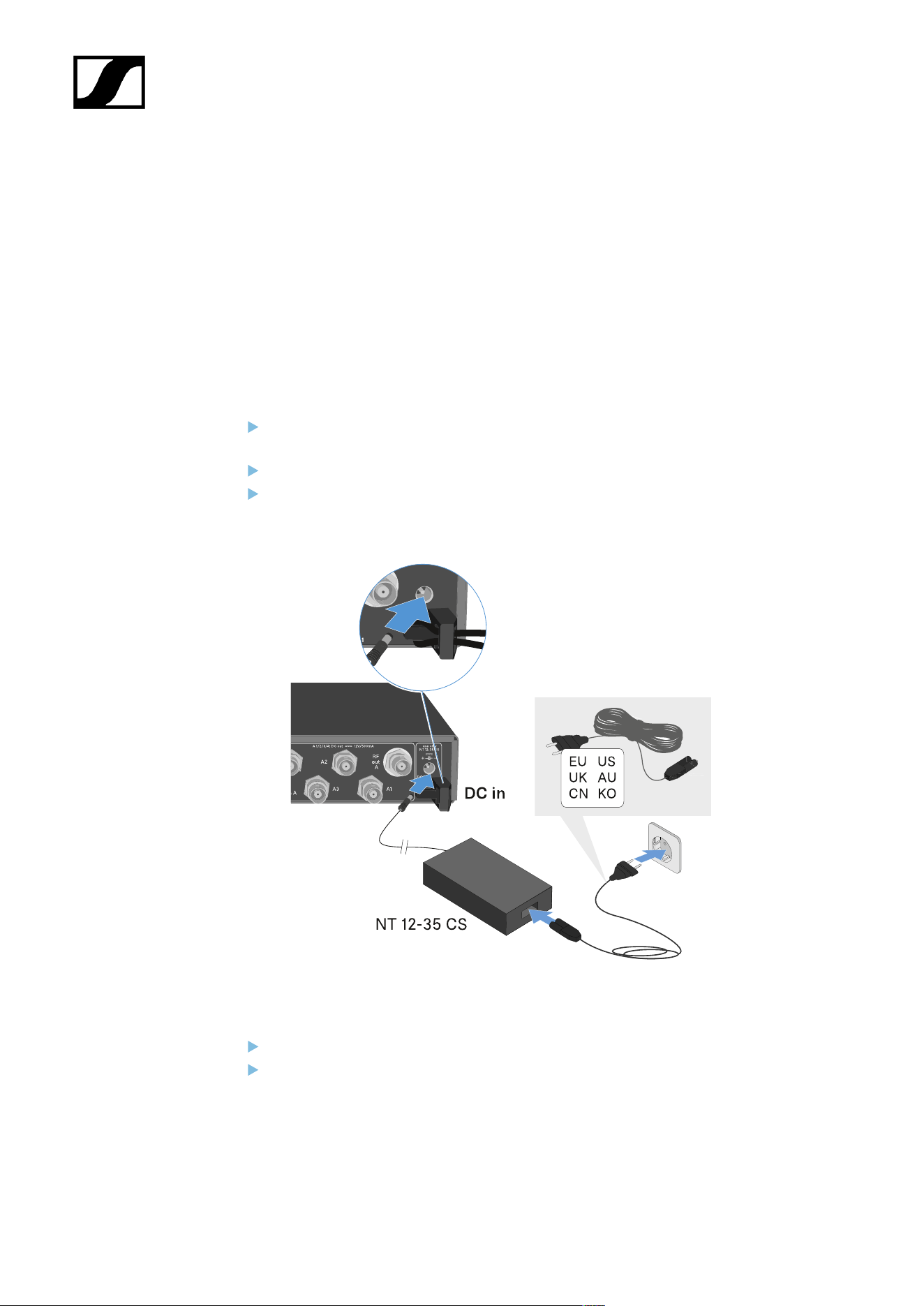
| 3 - Instruction manual
Connecting/disconnecting the EW-D ASA to/from the power
supply system
To supply power to the EW-D ASA, the connected receivers (EW-D EM only) and any antenna
amplifiers used, you will need the NT 12-35 CS power supply unit.
Use only the supplied NT 12-35 CS power supply unit. It is designed for your antenna splitter
and ensures safe operation.
To connect the EW-D ASA antenna splitter to the power supply system:
Plug the hollow jack plug of the power supply unit into the DC in socket of the
antenna splitter.
Pass the cable of the power supply unit through the strain relief.
Connect one end of the power cord to the power supply unit and the other end to the
wall socket.
To completely disconnect the EW-D ASA antenna splitter from the power supply system:
Unplug the power cable from the wall socket.
Unplug the hollow jack plug of the power supply unit from the DC in socket of the
antenna splitter.
508
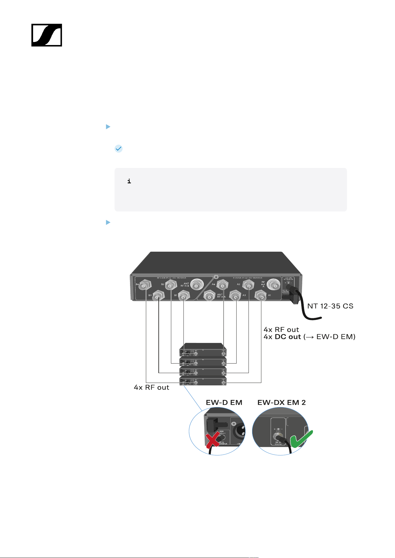
| 3 - Instruction manual
Connecting receivers to the EW-D ASA
You can connect and operate up to four EW-D EM or EW-DX EM 2 rack receivers with the
EW-D ASA.
To connect the receivers to the EW-D ASA antenna splitter:
Connect one of the receiver’s antenna inputs to one of the BNC sockets A1 to A4
using one of the supplied BNC cables.
The EW-D EM receivers do not require their own power supply. They are
powered via the BNC sockets A1 to A4.
The EW-DX EM 2 receivers cannot be supplied with power via the BNC
sockets. They need to be powered by the included power supply unit or
by PoE.
Connect the receiver’s other antenna input to one of the BNC sockets B1 to B4 using
one of the supplied BNC cables.
509
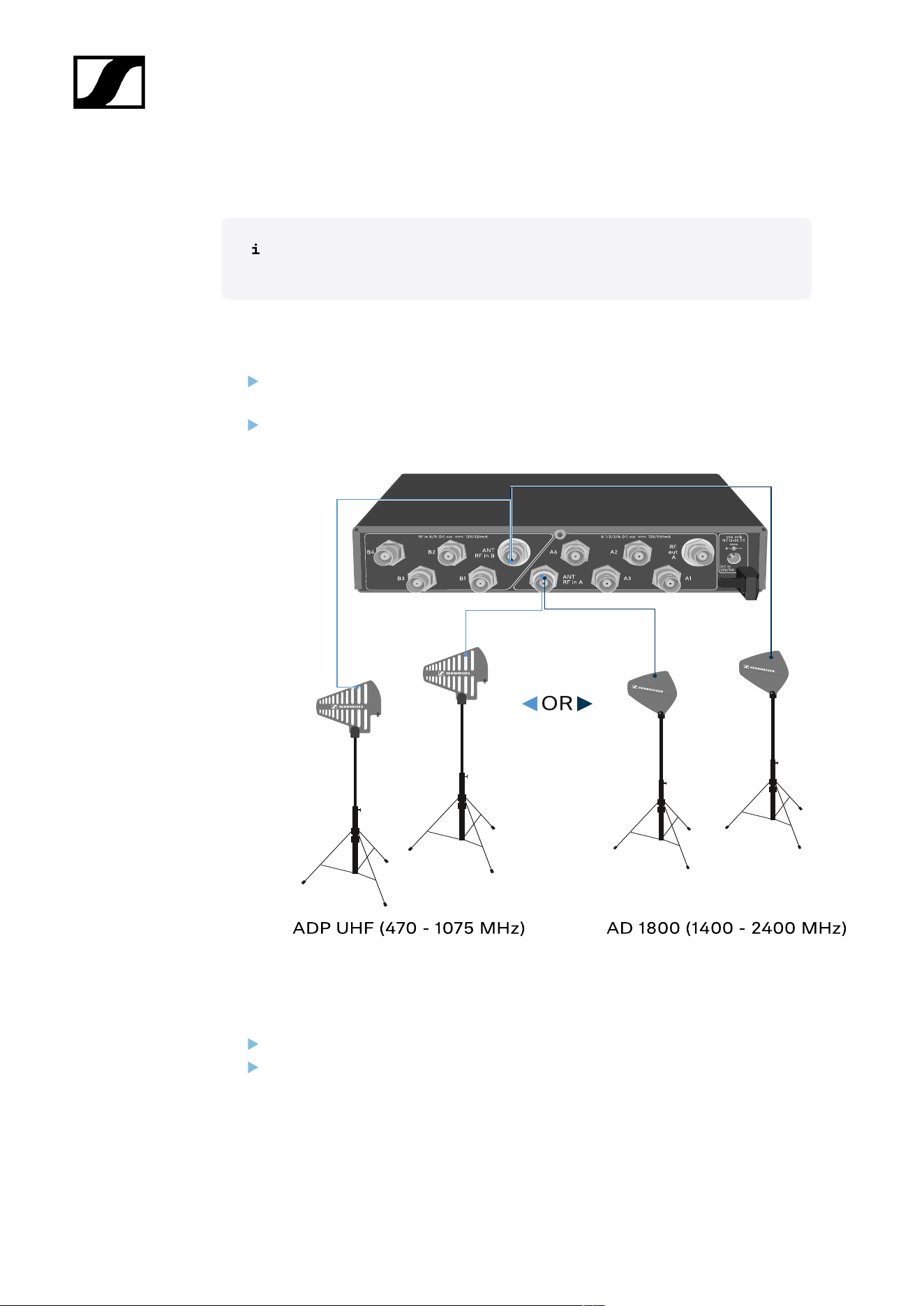
| 3 - Instruction manual
Connecting antennas
To ensure optimal reception even in the case of poor reception conditions, we
recommend using remote antennas.
Connecting remote antennas
Mount an antenna each or a combination of an antenna and an antenna amplifier to
the BNC sockets ANT RF IN A and ANT RF IN B.
Refer to the instructions under Information on antenna amplifiers and cable lengths.
Connecting rod antennas
Mount the antennas to the BNC sockets ANT RF IN A and ANT RF IN B.
Align the antennas in a V-shape in order to ensure the best possible reception.
510

| 3 - Instruction manual
Information on antenna amplifiers and cable lengths
The following table shows which cable lengths require the use of the EW-D AB antenna
amplifier as well as the maximum recommended cable lengths.
Frequency range
around
Number of EW-D AB
Max. cable length
RG 58
Max. cable length
GZK 5000
0 8 m 16 m
1 36 m 72 m
500 MHz
2 64 m 128 m
0 7 m 14 m
1 30 m 60 m
700 MHz
2 53 m 106 m
0 6 m 12 m
1 26 m 52 m
900 MHz
2 46 m 92 m
0 4 m 8 m
1 16 m 36 m
1800 MHz
2 28 m 64 m
For frequency variants of the EW-D AB, see EW-D AB antenna booster.
511
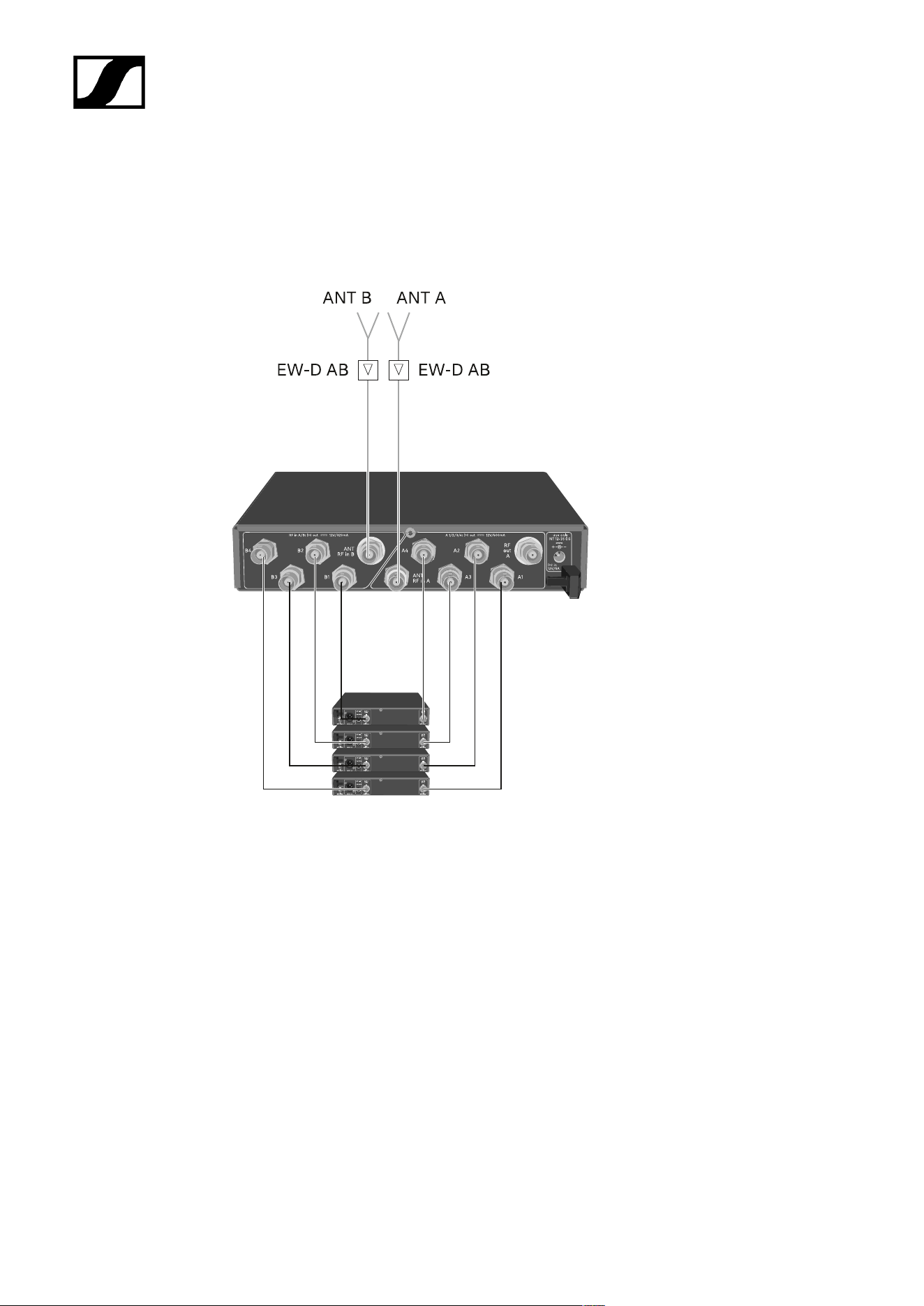
| 3 - Instruction manual
Configuring multi-channel systems
The following options for connecting multi-channel systems are possible:
Option 1: Two antennas supply a 4-channel system
512
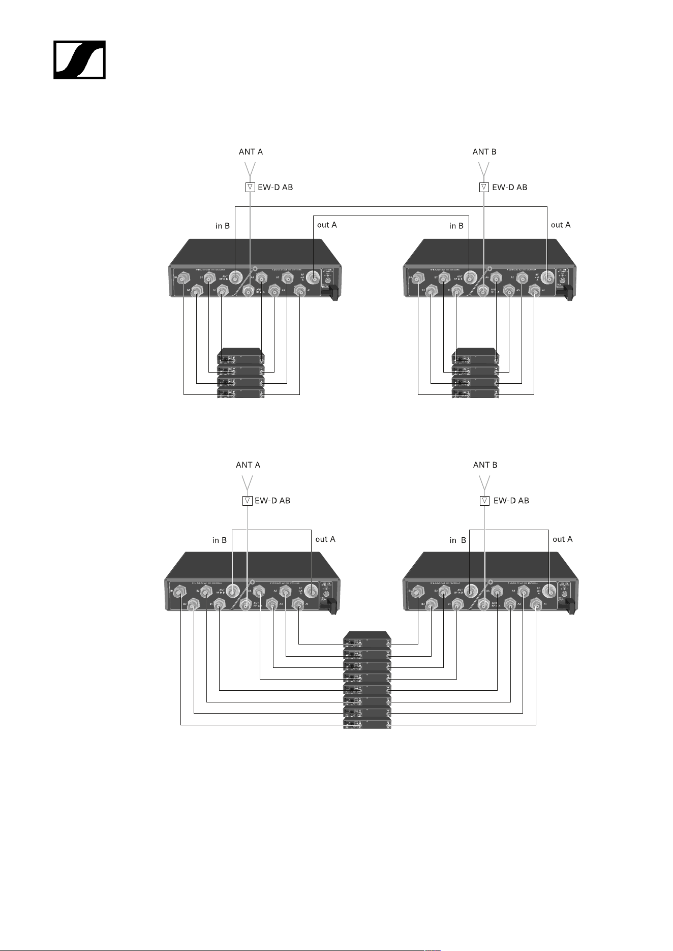
| 3 - Instruction manual
Option 2: Two 4-channel systems are interconnected
Option 3: Two antennas supply a 8-channel system
513
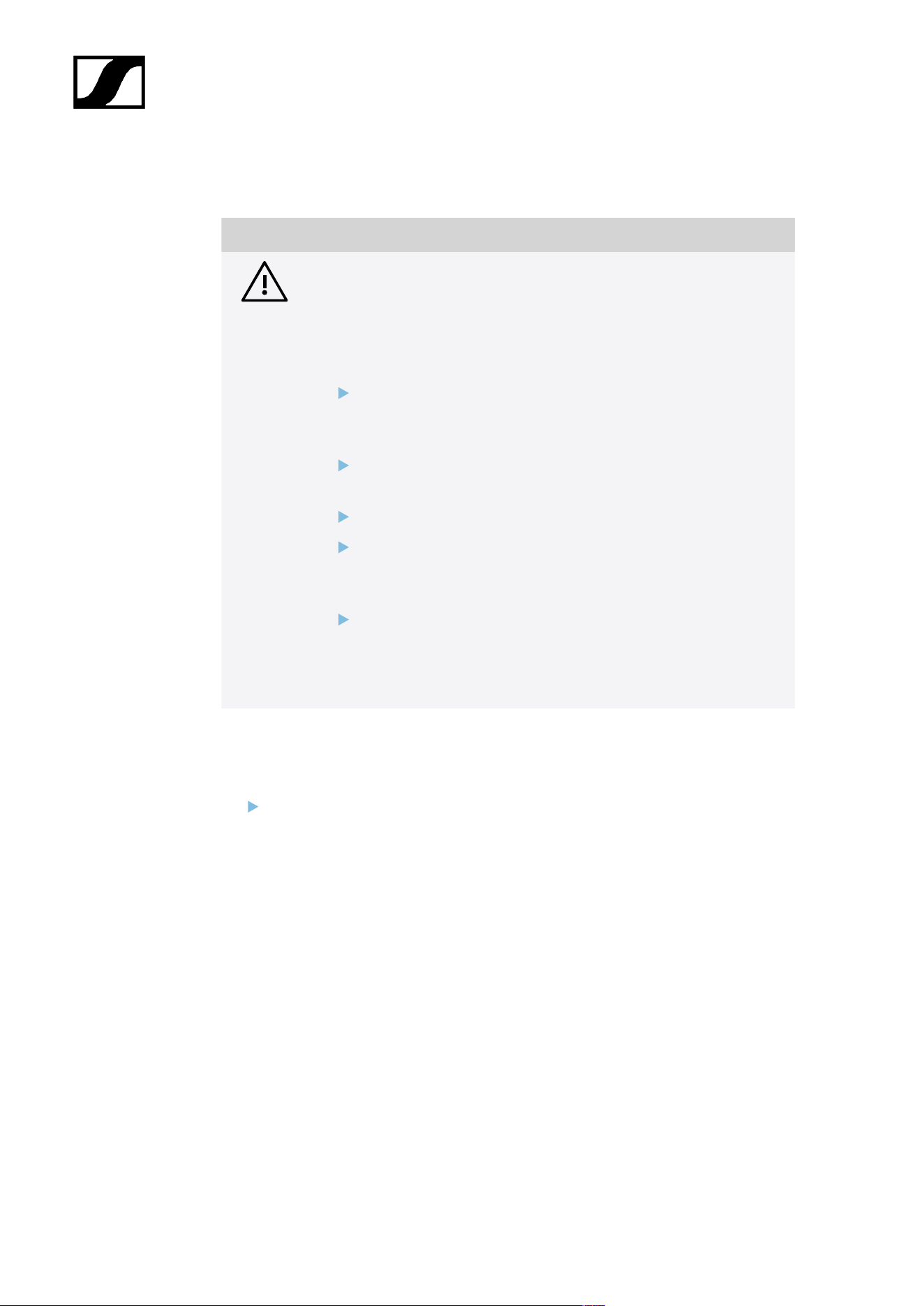
| 3 - Instruction manual
Installing the EW-D ASA in a rack
NOTICE
Rack mounting poses risks!
When installing the device in a closed 19" rack or multi-rack assembly,
please consider that, during operation, the ambient temperature, the
mechanical load and the electrical potentials will be different from those
of devices which are not mounted into a rack.
Make sure that the ambient temperature within the rack does
not exceed the permissible temperature limit stated in the
specifications. See (Specifications).
Ensure sufficient ventilation; if necessary, provide additional
ventilation.
Make sure that the mechanical load of the rack is even.
When connecting to the power supply system, observe the
information indicated on the type plate. Avoid overloading the
circuits. If necessary, provide overcurrent protection.
When mounting in a rack, please note that intrinsically harmless
leakage currents of the individual power supply units may
accumulate, thereby exceeding the permissible limit value. As a
remedy, ground the rack via an additional ground connection.
To mount the antenna splitter in a rack, you will need the GA 3 rack mount kit (optional
accessory).
Rack mounting is carried out in the same way as for the EW-D EM receiver: see
Installing receivers in a rack.
514
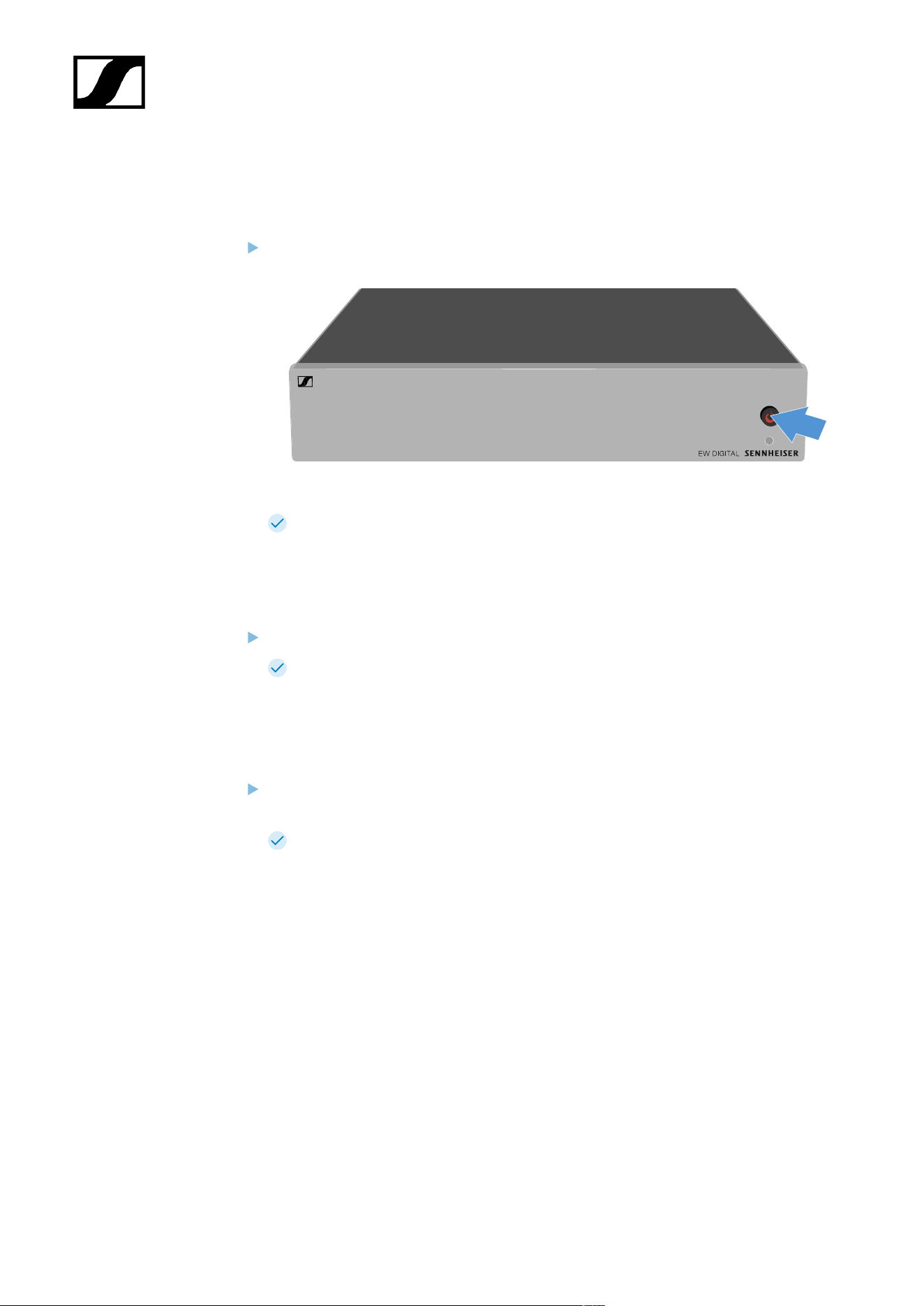
| 3 - Instruction manual
Switching the EW-D ASA on and off
To switch on the antenna splitter:
Short-press the STANDBY button.
The antenna splitter switches on and the power LED turns green.
The RF signals of the connected antennas are distributed to all connected receivers.
To switch the antenna splitter to standby mode:
Press the STANDBY button for approx. 2 seconds.
The LED turns off. The connected antenna amplifiers are switched off. Connected
receivers are switched off if they draw their supply voltage from the BNC sockets A1
to A4 (see Connecting receivers to the EW-D ASA).
To fully switch off the antenna splitter:
Disconnect the antenna splitter from the power supply system by unplugging the
power supply unit from the wall socket.
The LED turns off.
515
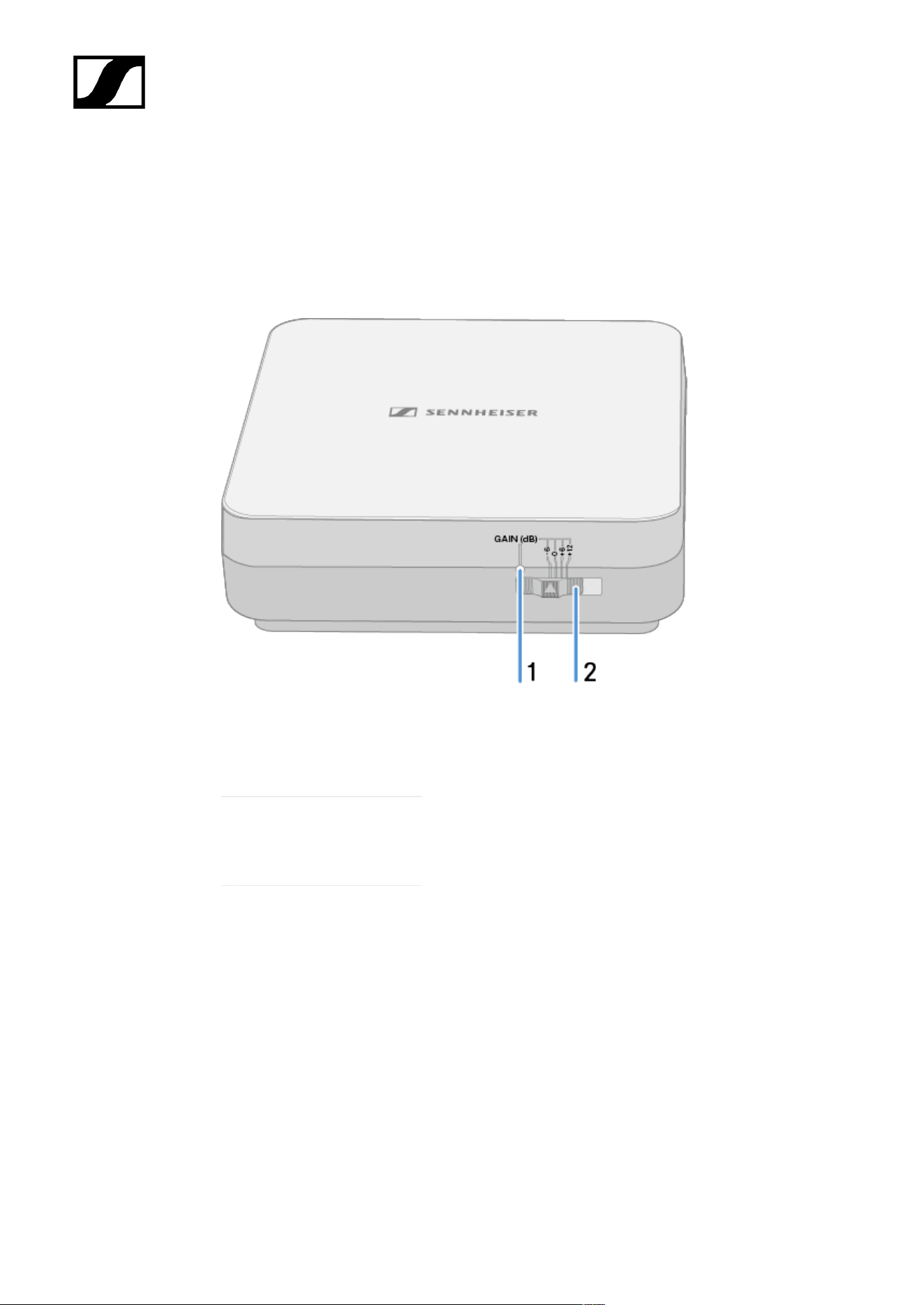
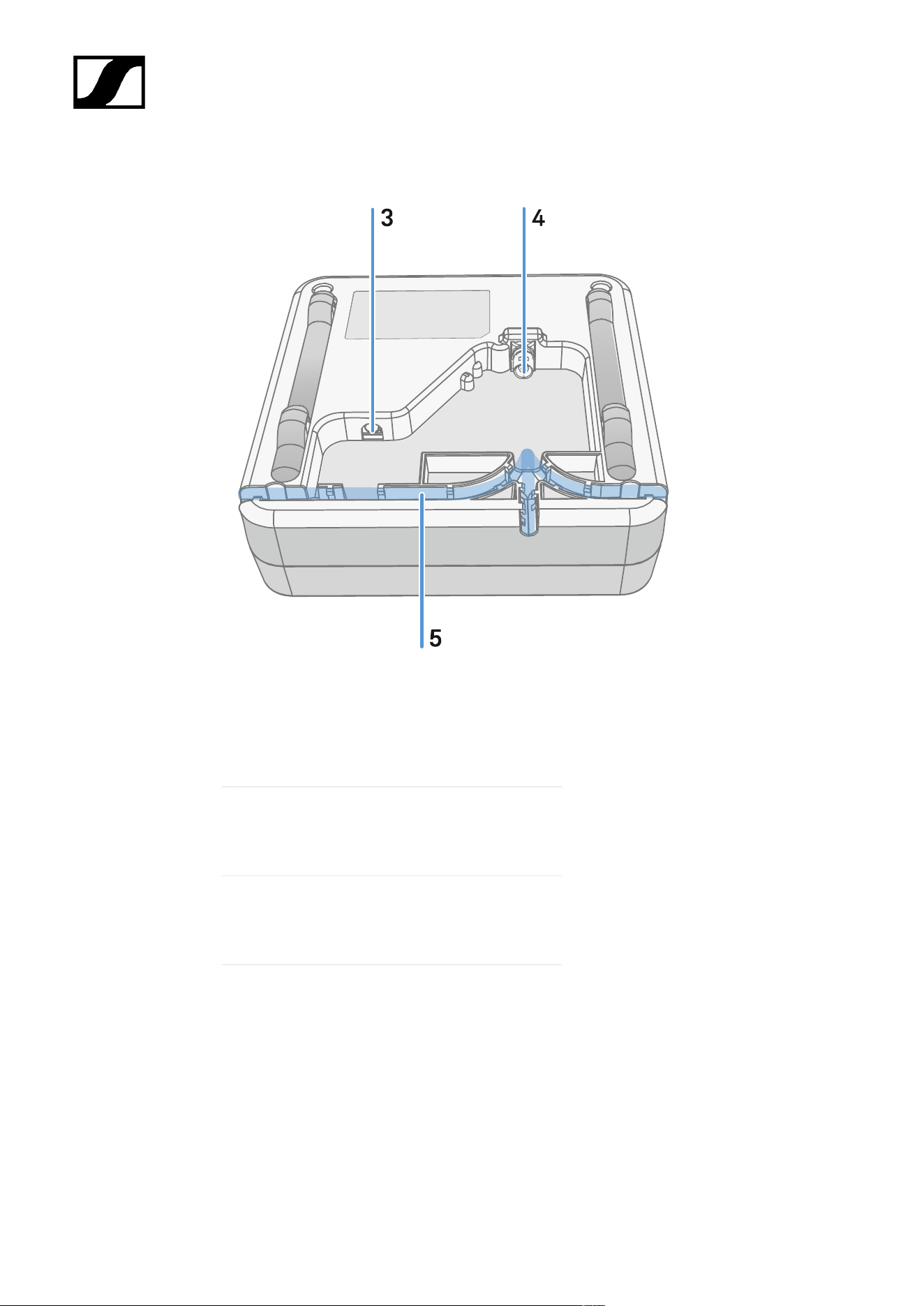
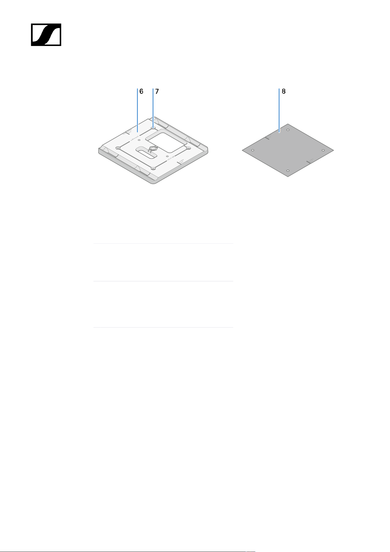
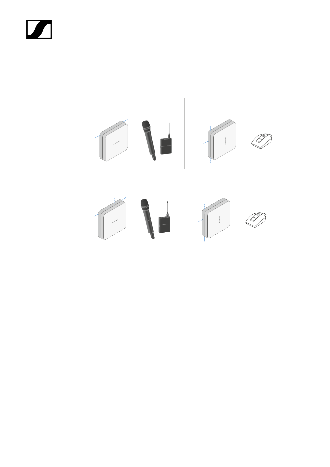
| 3 - Instruction manual
Antenna setup
Instructions for optimum interaction with Sennheiser transmitters (system polarization)
Recommended setups depending on the antennas – polarization:
B
A
C
A Vertical (normal orientation)
• Suitable for hand-held or bodypack transmitters
B Horizontal (rotated orientation)
• Suitable for table stands
C Vertical and horizontal (mixed orientation)
• Suitable for mixed transmitter types
519

| 3 - Instruction manual
Connecting the cable to the antenna
Information on connecting the antenna:
• Observe the recommended cable lengths, see Recommended cable lengths.
• The cable diameter must be <6 mm to fit in the cable sheath.
• Observe the length of the cable within the antenna, see Cable sheath options.
• The DC connection is optional and provides an alternative to the DC supply via the
BNC cable.
• The EW-DX EM 4 Dante and EW-D ASA devices supply the antenna with
voltage via the BNC cable, meaning no additional DC supply is required.
• With the EW-D EM, EW-DX EM 2 and EW-DX EM 2 Dante devices, a power
supply via the DC connection is required.
The antenna is supplied with power via the RF or DC cable. As soon as the
power supply is established, the antenna switches on automatically. There is no
separate on/off switch.
To connect the cable to the antenna:
If necessary, connect the DC cable to the DC in socket.
We recommend using the EW-D power supply unit (art. no. 509454).
Run the cable out to one side.
Connect the RF cable to the RF in socket.
Run the cable out to the same side.
Alternatively, you can connect the cables through an opening in the wall.
Cable sheath options:
The cable sheath enables optimum antenna characteristics and also enables a plastic cable
duct to be laid to discreetly conceal the cables directly up to the antenna housing.
• A RF cable length in the antenna >205 mm
• B RF cable length in the antenna >110 mm
• C RF cable length in the antenna >140 mm
520

| 3 - Instruction manual
521

| 3 - Instruction manual
Recommended cable lengths
To ensure reliable operation, observe the following maximum antenna cable lengths and
adjust the gain accordingly:
Note the corresponding values in the data sheet of the antenna cable used.
Frequency
range around
Gain
Max. cable
length RG 58
Max. cable
length GZL RG 8x
-6 dB 4.5 m 9 m
0 dB 9 m 18 m
+6 dB 18 m 36 m
500 MHz
+12 dB 36 m 72 m
-6 dB 3.5 m 7 m
0 dB 7 m 14 m
+6 dB 14 m 28 m
700 MHz
+12 dB 28 m 56 m
-6 dB 3 m 6 m
0 dB 6 m 12 m
+6 dB 12 m 24 m
900 MHz
+12 dB 24 m 48 m
-6 dB 2 m 4 m
0 dB 4 m 8 m
+6 dB 8 m 16 m
1800 MHz
+12 dB 16 m 32 m
522
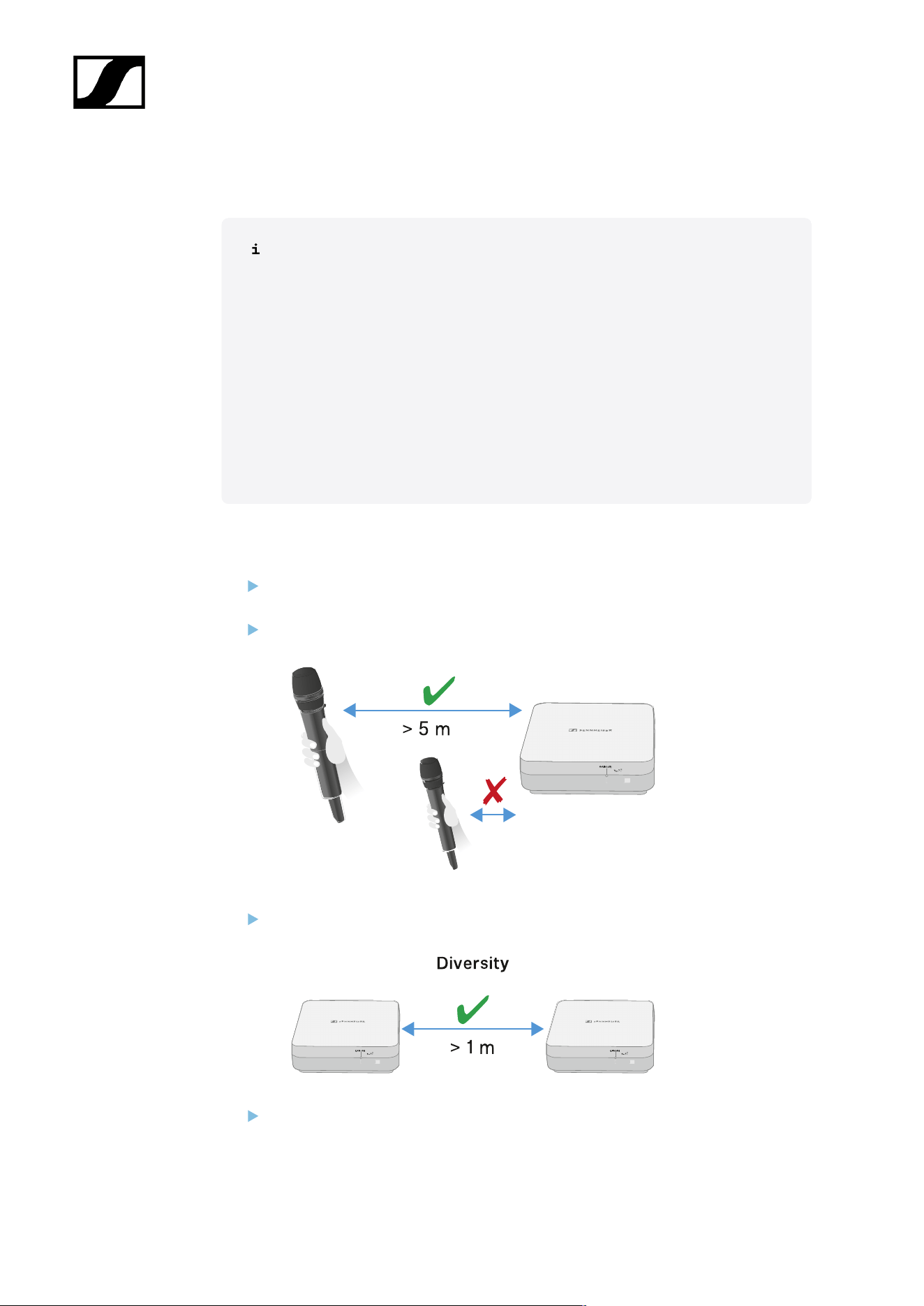
| 3 - Instruction manual
Installing and mounting the antenna
Safety instructions for installation
Observe the following safety instructions when installing the product:
• The physical mounting and all electrical installations must be performed
by a specialist.
• The specialist must have sufficient professional training, experience and
knowledge of applicable provisions, regulations and standards to be able
to properly assess the work assigned to them, identify possible hazards
and take appropriate safety measures.
• When mounting the product, observe and follow all local, national and
international regulations and standards.
Observe the following instructions when installing the antenna:
If possible, position the antennas so that there is a direct line of sight (without
obstacles) between the transmitters and the antennas.
The distance between the antenna and transmitter must be >5 m.
The distance between two antennas must be >1 m.
In the case of neighboring systems with a high interference level, reduce the gain if
the wanted signal is strong enough. See Setting the gain.
523
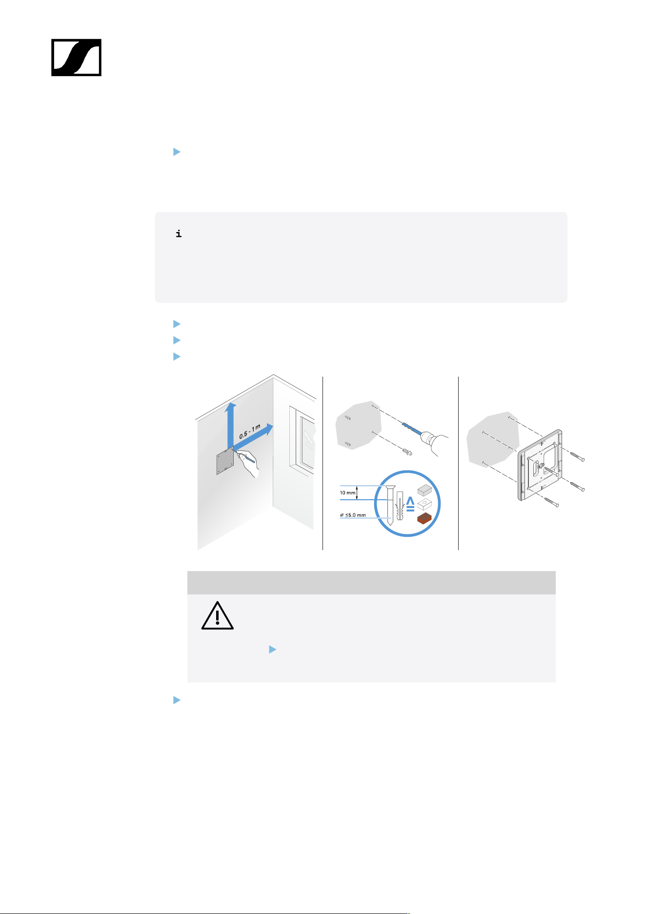
| 3 - Instruction manual
Mounting the antenna on the wall
Before mounting the antenna, see the information in chapter Installing and mounting
the antenna.
To mount the antenna on the wall:
For wall mounting, you will need the mounting frame supplied.
Screws and anchors for mounting the product to the wall are not included
with delivery. Use screws and anchors that are appropriate for the particular
characteristics of your wall.
Use the included drilling template to mark the drill holes for wall mounting.
Maintain a distance of 0.5 m to 1 m from other walls and the ceiling.
Screw the mounting frame to the wall using four suitable screws and anchors.
NOTICE
Damage to the product due to incorrect mounting.
Otherwise the product may fall and be damaged.
The top marking on the mounting frame must not point
downward.
Make sure that the mounting frame is aligned correctly.
524
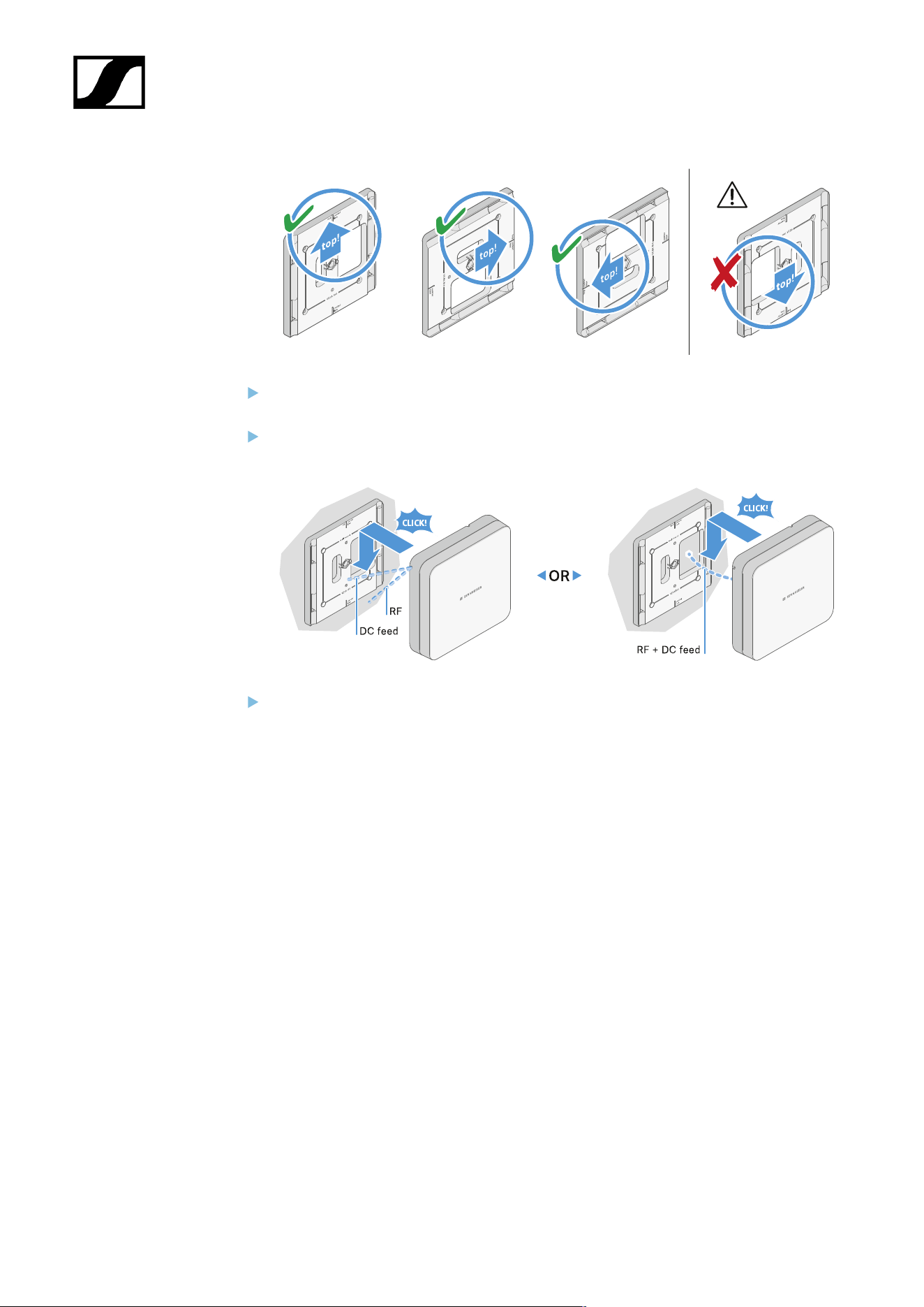
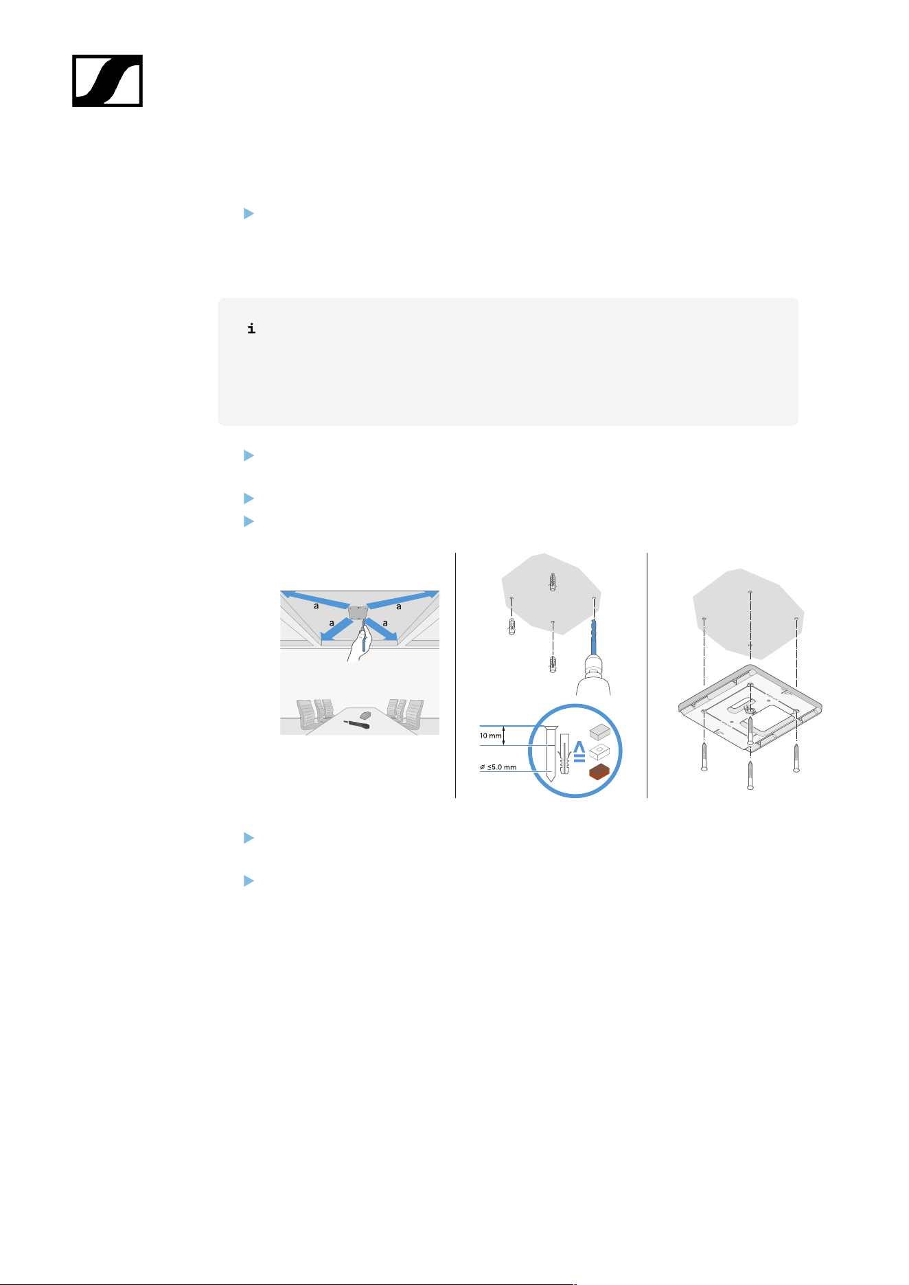
| 3 - Instruction manual
Mounting the antenna on the ceiling
Before mounting the antenna, see the information in chapter Installing and mounting
the antenna.
To mount the antenna on the ceiling:
For wall mounting, you will need the mounting frame supplied.
Screws and anchors for mounting the product to the wall are not included
with delivery. Use screws and anchors that are appropriate for the particular
characteristics of your wall.
Use the included drilling template to mark the drill holes for ceiling mounting.
The optimum placement of the antenna is in the middle of the ceiling.
Maintain a minimum distance of 0.5 m to 1 m from the walls.
Screw the mounting frame to the ceiling using four suitable screws and anchors.
Connect the cable to the antenna as described under Connecting the cable to the
antenna.
Insert the receiver into the mounting frame as shown until you hear it click into place.
526
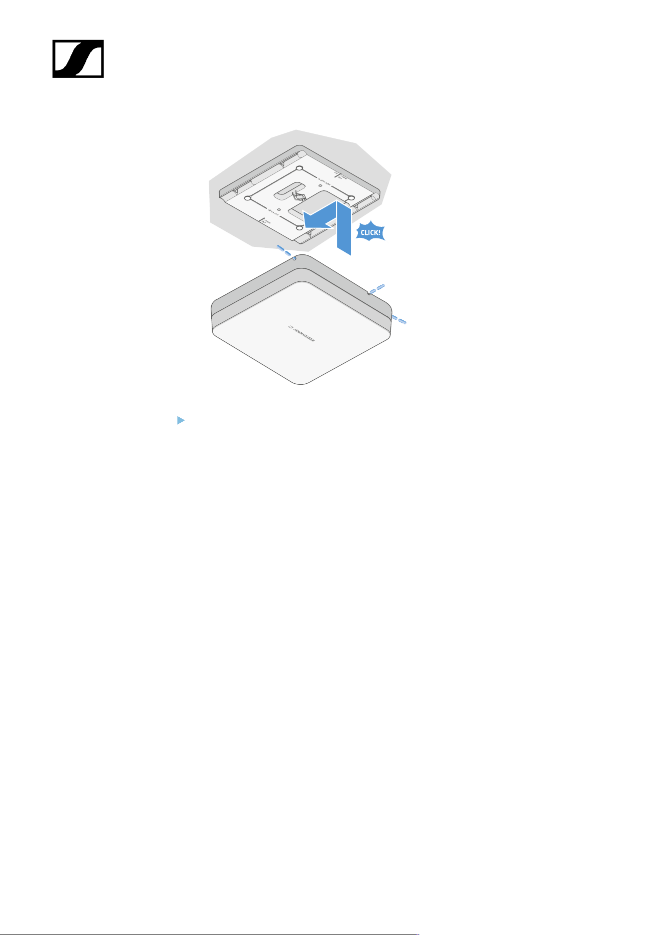
| 3 - Instruction manual
Check that the antenna is correctly seated in the mount.
527
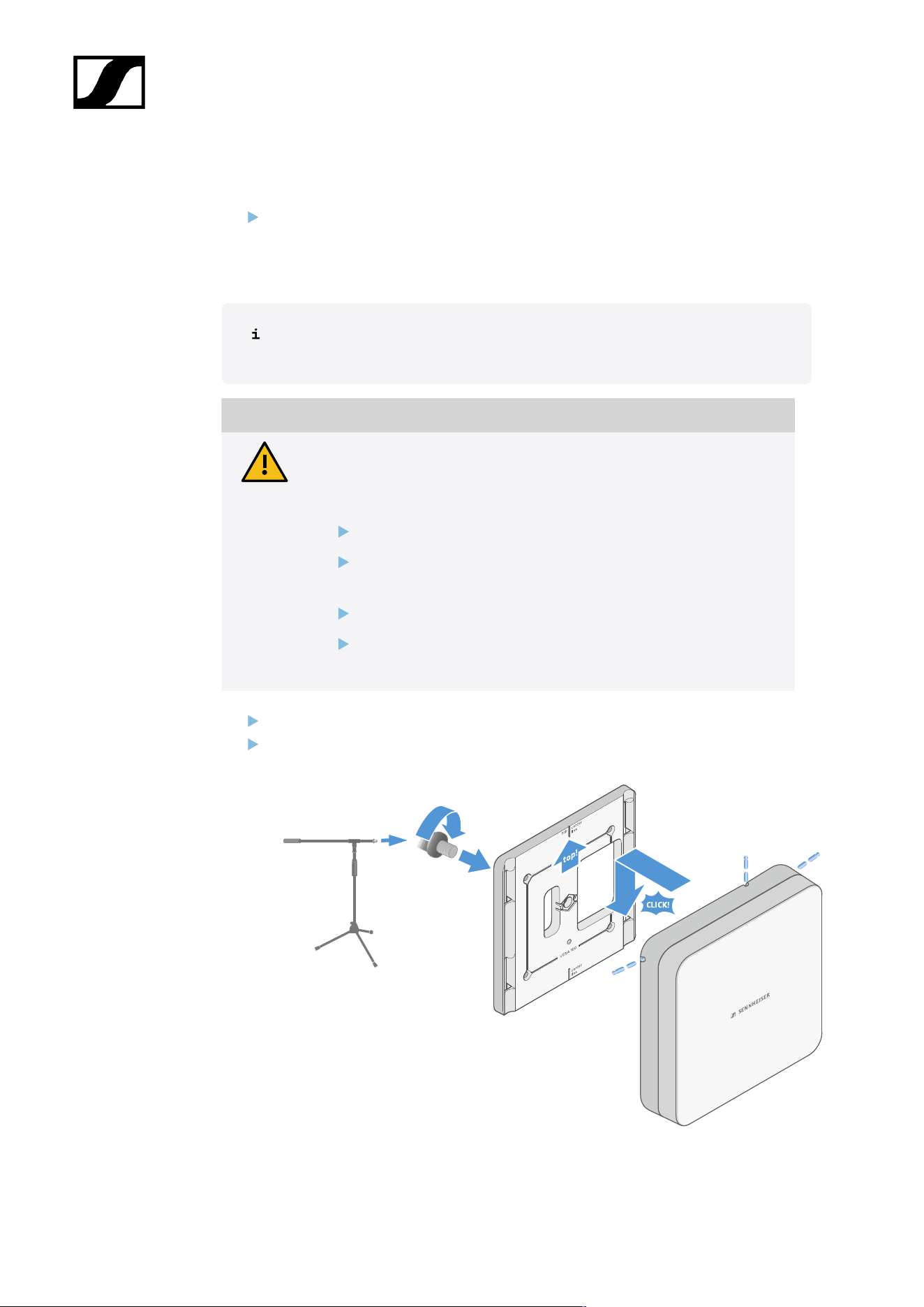
| 3 - Instruction manual
Mounting the antenna on a stand
Before mounting the antenna, see the information in chapter Installing and mounting
the antenna.
To mount the antenna on a stand:
The thread in the middle of the mounting frame is suitable for mounting on a
standard microphone stand with boom arm and 3/8" thread.
CAUTION
Danger due to falling objects
If you mount the antenna improperly on the stand, the stand and receiver
may tip over. This can cause personal injury and damage to property.
Use a stand that is designed for a central load of 5 kg.
Adjust the length of the boom arm as short as possible, as shown
in the figure.
Set the height of the stand to a maximum of 2 meters.
Make sure that the total weight of the stand and the mounted
receiver does not exceed 7 kg.
Screw the mounting frame onto the microphone stand as shown.
Insert the antenna into the mounting frame as shown until you hear it click into place.
528
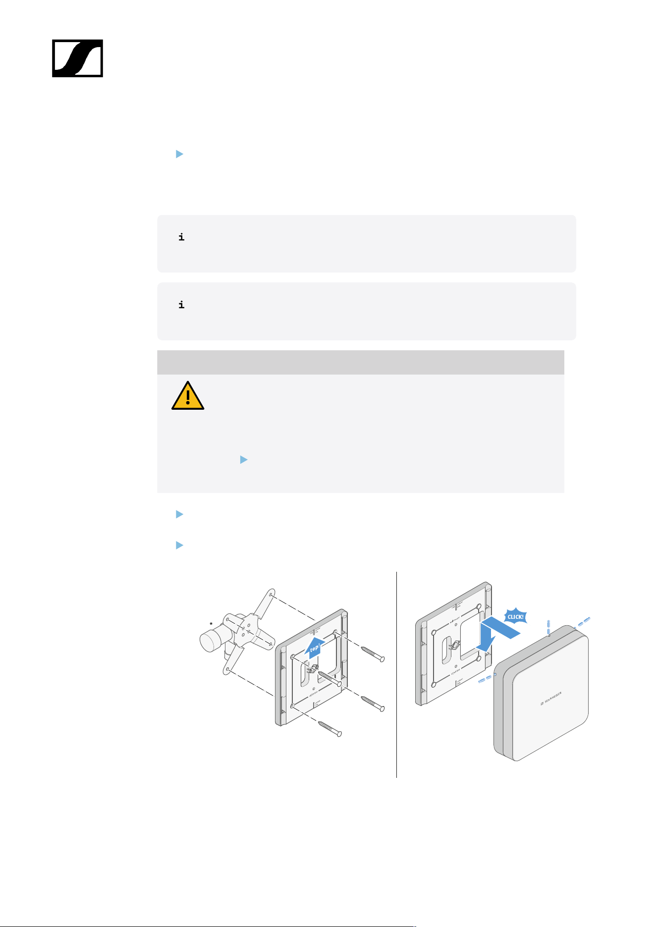
| 3 - Instruction manual
Mounting the antenna on a VESA mount
Before mounting the antenna, see the information in chapter Installing and mounting
the antenna.
To mount the antenna on a VESA mount:
The holes in the mounting frame are positioned 100 mm apart so that the
mounting frame can be mounted on any VESA 100 mount.
The antenna characteristics can be changed depending on the type of VESA
mount (geometry/material).
CAUTION
Danger due to falling objects
If you mount the antenna incorrectly on the VESA mount, the VESA mount
and receiver may fall down. This can cause personal injury and damage
to property.
Follow the installation and safety instructions from the
manufacturer of the VESA mount.
Screw the mounting frame onto the VESA mount as shown using four suitable screws
(not supplied).
Insert the antenna into the mounting frame as shown until you hear it click into place.
*Example image of a VESA 100 mount
529
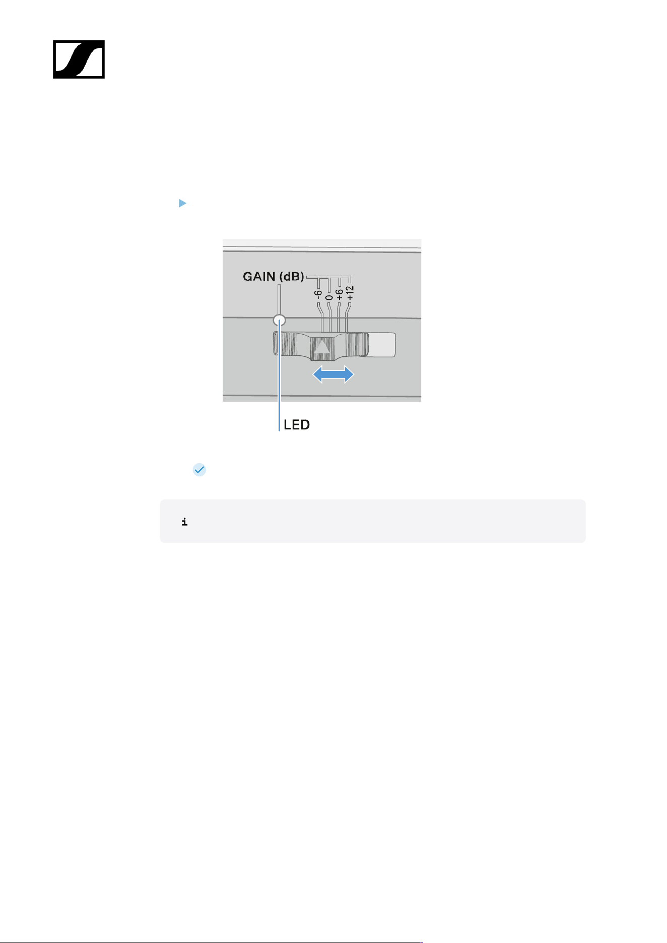
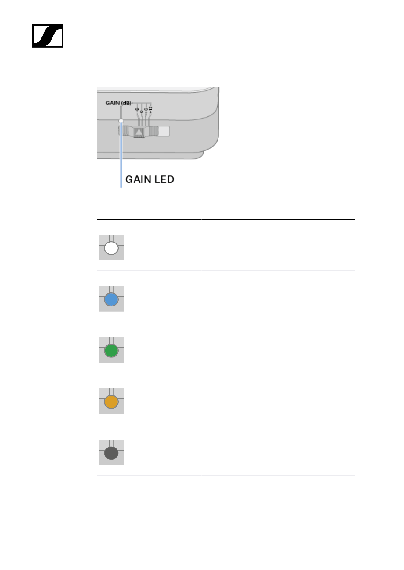
| 3 - Instruction manual
GAIN LED
The GAIN LED on the front of the antenna can indicate the following information.
The LED is white: Gain set to +12 dB.
The LED is blue: Gain set to +6 dB.
The LED is green: Gain set to 0 dB.
The LED is orange: Gain set to -6 dB.
The LED is off: no or insufficient power supply.
531
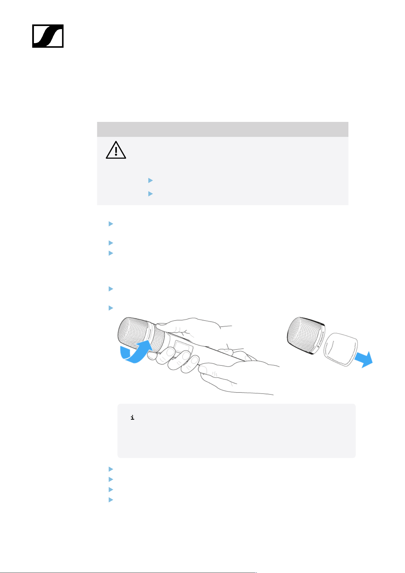
| 3 - Instruction manual
Cleaning and maintenance
Note the following information when cleaning and maintaining products of the Evolution
Wireless Digital series.
NOTICE
Liquids can damage the products’ electronics.
Liquids entering the product housing can cause a short-circuit and
damage the electronics.
Keep all liquids away from the products.
Do not use any solvents or cleansing agents.
Disconnect the products from the power supply system and remove rechargeable
batteries and batteries before you begin cleaning.
Clean all products only with a soft, dry cloth.
Note the special cleaning instructions below for the following products.
Cleaning the sound inlet basket of the microphone module
Unscrew the top sound inlet basket from the microphone module by turning it
counterclockwise.
Remove the foam insert.
You can clean the sound inlet basket in two ways:
• Use a slightly damp cloth to clean the top sound inlet basket from
the inside and outside.
• Use a brush and rinse with clean water.
If necessary, clean the foam insert with a mild detergent or replace the foam insert.
Dry the top sound inlet basket and foam insert.
Reinsert the foam insert.
Screw the sound inlet basket back onto the microphone module.
532

| 3 - Instruction manual
From time to time, you should also clean the microphone module contacts:
Wipe the contacts of the microphone module with a soft, dry cloth.
Cleaning the transmitter’s contacts
Wipe the contacts with a dry cloth.
Cleaning the L 70 USB and CHG 70N chargers
Remove all rechargeable batteries from the charging slots.
Disconnect the charger from the power supply system before cleaning.
Clean the product with a dry cloth.
In addition, use a brush to remove dust from the charging slots.
Clean the charging contacts from time to time with a cotton swab, for instance.
533

Evolution Wireless Digital
4. Knowledge base
Central hub for information, resources, and guides with further content on the product and/
or service.
FAQ
This section contains answers to frequently asked questions and further information.
Radio and frequencies
This section contains answers to frequently asked questions and further information about
the following topics:
Why won’t my transmitter synchronize with my receiver?
• Briefly press the SYNC button on both devices, but don’t press too long (Establishing
a radio link | Synchronizing the receiver and transmitter)
• The two devices must have the same frequency range (Frequency ranges)
What is the transmission range of the transmitter?
• Up to 100 m in an ideal environment (without obstacles)
What is the best way to wear the bodypack transmitter?
• Do not kink, bend or cover the antenna
• Avoid skin contact with the antenna
• If possible, attach it to your clothing with the belt clip
How do I know which transmitter is coupled to which receiver?
• EW-D SKM-S: Identifying the paired receiver (Identify function)
• EW-D SK: Identifying the paired receiver (Identify function)
• EW-DX SKM(-S): Identifying the paired receiver (Identify function)
• EW-DX SK (3-PIN): Identifying the paired receiver (Identify function)
• Additional option: Use color coding: Using EW-D Color Coding Sets to label
transmission paths
534

| 4 - Knowledge base
How can I distinguish between my wireless links without displays on the
transmitters?
• EW-DX SKM(-S): Identifying the paired receiver (Identify function)
• EW-DX SK (3-PIN): Identifying the paired receiver (Identify function)
• Additional option: Use color coding: Using EW-D Color Coding Sets to label
transmission paths
The transmitter and receiver are synchronized, but there is no connection.
• Install antennas correctly on the receiver (EW-D EM: Connecting antennas | EW-DX
EM 2: Connecting antennas
• EW-D: Use the scan function to find a free channel AUTO SCAN menu item and
synchronize the transmitter again Establishing a radio link | Synchronizing the
receiver and transmitter
• EW-DX: Using the Auto Setup function, find a free channel Ch 1 / Ch 2 -> Scan /
Auto Setup menu item and resynchronize the transmitter Establishing a radio link |
Synchronizing the receiver and transmitter
The display on the receiver shows signal levels even though the paired
transmitter is not switched on.
• There may be interfering frequencies (e.g. TV channels)
• EW-D: Use the scan function to find a free channel AUTO SCAN menu item and
synchronize the transmitter again Establishing a radio link | Synchronizing the
receiver and transmitter
• EW-DX: Using the Auto Setup function, find a free channel Ch 1 / Ch 2 -> Scan /
Auto Setup menu item and resynchronize the transmitter Establishing a radio link |
Synchronizing the receiver and transmitter
Which frequency ranges are available?
• Frequency ranges
535

| 4 - Knowledge base
Audio
Which microphones can I use with my bodypack transmitter?
• EW-D SK: Connecting a microphone to the bodypack transmitter
• EW-DX SK (3-PIN): Connecting a microphone to the bodypack transmitter
Which microphone modules can I use with my handheld transmitter?
• EW-D SKM-S: Replacing the microphone module
• EW-DX SKM(-S): Replacing the microphone module
What exactly do the “Gain” and “AF Out” settings do?
• Gain: Level of the audio signal coming from the transmitter (EW-D EM: GAIN menu
item | EW-DX EM 2 Ch 1 / Ch 2 -> Gain menu item)
• AF Out: Level of the audio signal coming from the receiver (EW-D EM: AF OUT menu
item | EW-DX EM 2 Ch 1 / Ch 2 -> AF Out menu item)
How do I adjust the settings so that my wireless link has the same volume as
my guitar cable?
• EW-D: Configure unity gain settings under the menu items GAIN (volume that
reaches the receiver from the guitar through the bodypack transmitter – GAIN menu
item) and AF OUT (volume output from the receiver to the guitar amplifier – AF OUT
menu item).
Possible unity gain settings (depending on the level of the incoming signal):
• AF Out 18 dB | Gain 27 dB
• AF Out 12 dB | Gain 33 dB
• AF Out 6 dB | Gain 39 dB
How can I adjust sensitivity on the transmitter?
• EW-D: You cannot make any settings on the transmitter. You can adjust the level of
the signal coming from the transmitter under the GAIN menu item (GAIN menu item)
on the receiver.
• EW-DX: In addition to the gain that is set in the receiver (Ch 1 / Ch 2 -> Gain menu
item), you can also set the trim on the transmitter (EW-DX SKM(-S): Trim menu item
| EW-DX SK (3-PIN): Trim menu item) to adjust the sensitivity to the incoming audio
signal.
536


| 4 - Knowledge base
Usability
This section contains answers to frequently asked questions and further information about
the following topics:
Why won’t my transmitter synchronize with my receiver?
• Briefly press the SYNC button on both devices, but don’t press too long (Establishing
a radio link | Synchronizing the receiver and transmitter)
• The two devices must have the same frequency range Frequency ranges
Is there a way to check the battery status of the transmitter other than on
the receiver?
• The Check function allows you to check the battery status on the transmitter.
• EW-D SKM-S: Checking the battery status of the transmitter (Check function)
• EW-D SK: Checking the battery status of the transmitter (Check function)
How do I know if my transmitter is switched on?
• The transmitter’s LINK LED lights up.
• EW-D SKM-S: Meaning of the LEDs
• EW-D SK: Meaning of the LEDs
• EW-DX SKM(-S): Meaning of the LEDs
• EW-DX SK (3-PIN): Meaning of the LEDs
My LINK LED is steady or flashing yellow. What does that mean?
• EW-D EM: Meaning of the LEDs
• EW-D SKM-S: Meaning of the LEDs
• EW-D SK: Meaning of the LEDs
• EW-DX EM 2: Meaning of the LEDs
• EW-DX SKM(-S): Meaning of the LEDs
• EW-DX SK (3-PIN): Meaning of the LEDs
My LINK LED is steady or flashing red. What does that mean?
• EW-D EM: Meaning of the LEDs
• EW-D SKM-S: Meaning of the LEDs
• EW-D SK: Meaning of the LEDs
• EW-DX EM 2: Meaning of the LEDs
• EW-DX SKM(-S): Meaning of the LEDs
• EW-DX SK (3-PIN): Meaning of the LEDs
538

| 4 - Knowledge base
Can I also operate an EW-D with desktop applications such as WSM or
Control Cockpit?
• No, that is not possible.
Can I also operate an EW-DX with desktop applications such as WSM or
Control Cockpit?
• Yes, the EW-DX can be operated with WSM and the Control Cockpit (Connecting
receivers in a network).
Is the Smart Assist app necessary to operate my devices?
• No, every device can also be operated without the Smart Assist app. However, the
app offers certain advantages (see Smart Assist app).
Can the transmitter and receiver connect to other Bluetooth-capable
systems?
• A Bluetooth connection be only be established between a receiver and a smartphone
with the Smart Assist app installed.
How can I turn on my transmitter without it transmitting immediately?
• Press and hold the SYNC button and then short-press the ON/OFF button (EW-D
SKM-S: Product overview / EW-D SK: Product overview).
Can the ew G4 and EW-D series be operated together?
• The products in the ew G4 and EW-D series are not compatible with each other.
However, you can operate the two series in parallel without any problems.
Are the receivers and transmitters of the EW-D and EW-DX series
compatible?
• Information on compatibility between EW-D, EW-DX and EW-DP
How can I distinguish between my wireless links without displays on the
transmitters?
• EW-D SKM-S: Identifying the paired receiver (Identify function)
• EW-D SK: Identifying the paired receiver (Identify function)
• Additional option: Use color coding (Using EW-D Color Coding Sets to label
transmission paths)
539

| 4 - Knowledge base
What exactly do the “Gain” and “AF Out” settings do?
• Gain: Level of the audio signal coming from the transmitter (EW-D EM: GAIN menu
item | EW-DX EM 2: Ch 1 / Ch 2 -> Gain menu item)
• AF Out: Level of the audio signal coming from the receiver (EW-D EM: AF OUT menu
item | EW-DX EM 2: Ch 1 / Ch 2 -> AF Out menu item)
What is the meaning of the Bluetooth icon on the receiver’s display?
• The receiver is paired to a smartphone, so you can make settings via the Smart Assist
app.
• Displays on the receiver’s display panel
• Smart Assist app
I don’t want a smartphone to have access to my receiver.
• Disconnect the Bluetooth pairing in your smartphone’s menu.
What is the best way to wear the bodypack transmitter?
• Do not kink, bend or cover the antenna
• Avoid skin contact with the antenna
• If possible, attach it to your clothing with the belt clip
Can you rotate the bodypack transmitter’s belt clip so that the antenna
points downward?
• Yes, see Changing the belt clip
How do I set the low-cut filter on the EW-DP SKP?
• The low-cut filter is set via the Smart Assist app.
• See: Activating/deactivating the low-cut filter.
540

| 4 - Knowledge base
Accessories
Which microphones can I use with my bodypack transmitter?
• EW-D SK: Connecting a microphone to the bodypack transmitter
• EW-DX SK (3-PIN): Connecting a microphone to the bodypack transmitter
Which microphone modules can I use with my handheld transmitter?
• EW-D SKM-S: Replacing the microphone module
• EW-DX SKM(-S): Replacing the microphone module
Which batteries can I use for my transmitter?
• 2x AA 1.5 V or
• Sennheiser BA 70 rechargeable battery: BA 70 rechargeable battery and L 70 USB
charger
• EW-D SKM-S: Inserting and removing the batteries/rechargeable batteries
• EW-D SK: Inserting and removing the batteries/rechargeable batteries
• EW-DX SKM(-S): Inserting and removing the batteries/rechargeable batteries
• EW-DX SK (3-PIN): Inserting and removing the batteries/rechargeable batteries
Can I use accessories that I already have from other microphone series?
• You can use passive devices without a power supply (e.g. AD 1800 or A 1031-U
antennas).
• You may already have compatible microphones or microphone modules:
• EW-D SK: Connecting a microphone to the bodypack transmitter
• EW-DX SK (3-PIN): Connecting a microphone to the bodypack transmitter
• EW-D SKM-S: Replacing the microphone module
• EW-DX SKM(-S): Replacing the microphone module
• We always recommend using the accessories that are optimized for the EW-D:
Accessories
Which antennas can I use with my receiver?
• In principle, you can use all antennas with BNC connectors that cover the frequency
ranges of the EW-D series (Frequency ranges)
• Recommended: Antennas
541
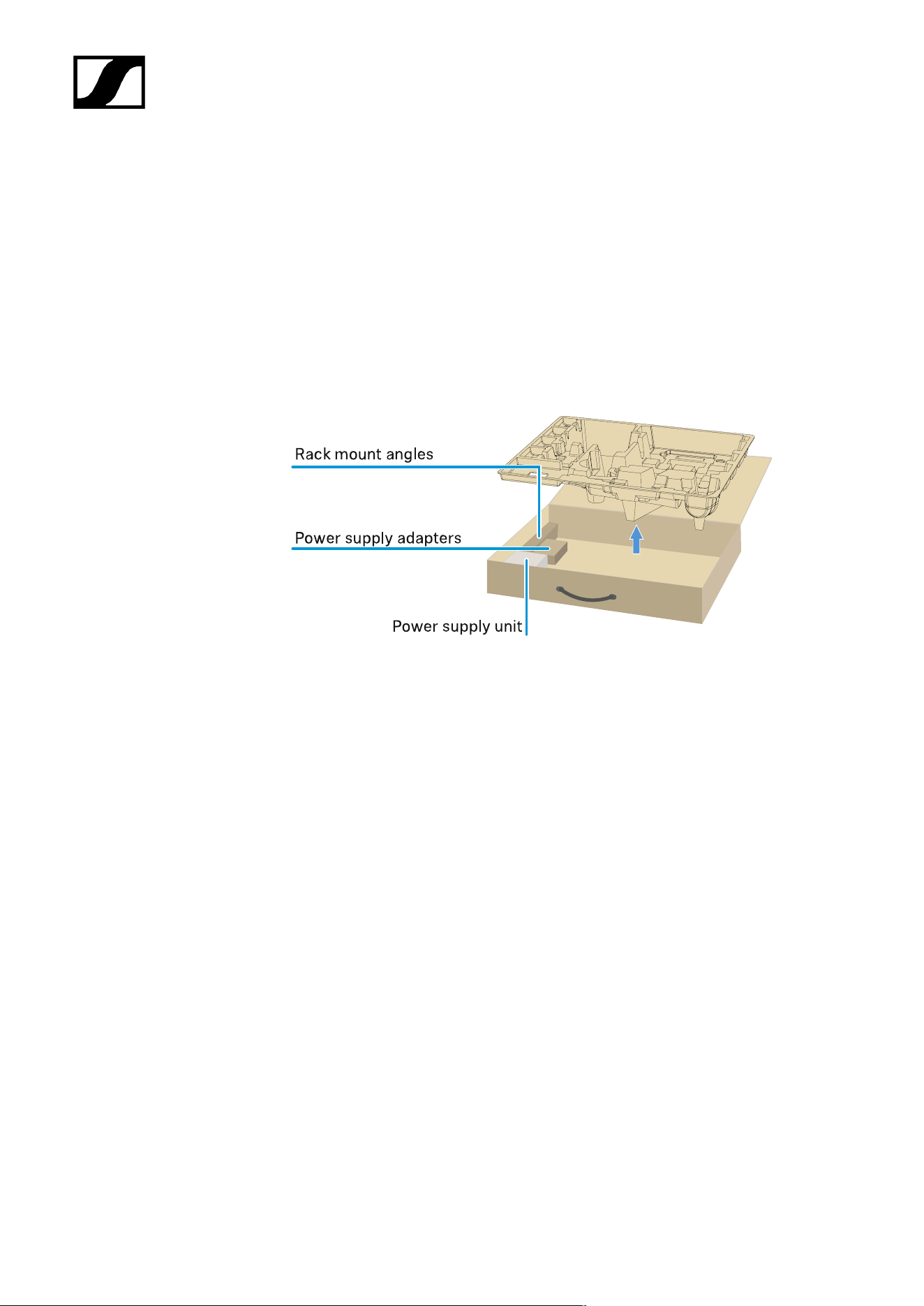
| 4 - Knowledge base
What are the advantages of the Half Wave Dipole rod antennas (available as
accessories) compared to the shorter rod antennas included with delivery?
• The Half Wave Dipole rod antennas have a higher antenna gain and therefore provide
greater transmission range in low-scatter and low-reflection environments (Rod
antennas).
My set is missing the power supply unit and the rack mounting bracket.
• Take out the packaging insert:
542

| 4 - Knowledge base
Smart Assist app
Is the Smart Assist app necessary to operate my devices?
• No, every device can also be operated without the Smart Assist app. However, the
app offers certain advantages (see Smart Assist app).
I want to see if the app is right for me before registering. Where can I get
more information?
• In the app’s demo mode or on the website: sennheiser.com/smart-assist
In which languages is the app available?
• English
• German
• French
• Spanish
• Portuguese
• Russian
• Chinese
• Korean
• Arabic
Can I pair multiple smartphones with a single receiver?
• No, you can pair only one smartphone with the receiver.
How many devices can I operate with my app?
• Up to 16 channels
How do I create a setup with 2 or more devices?
• Use the Add Device and Auto Scan functions. The app will lead you step by step
through the process.
Can I set a specific frequency range for the Auto Scan function?
• No, the function scans the entire available frequency spectrum.
Why can’t I access a receiver?
• The receiver may be switched off or out of Bluetooth range.
543

| 4 - Knowledge base
How are the app and the receivers connected to the app secured against
possible misuse?
• To pair a receiver and a smartphone, both devices must be physically present.
Only after successful pairing can values in the receiver be changed via the
smartphone.
Can I use a Bluetooth dongle to operate the app on a computer?
• No. The app is only available for iOS and Android.
How can I display the app on a larger screen?
• You can use a mirroring service such as QuickTime. However, you still control the app
from the smartphone.
544

Evolution Wireless Digital
5. Specifications
All specifications at a glance.
System
Audio link frequency ranges for EW-D, EW-DP
• Q1-6: 470.2 – 526 MHz
• R1–6: 520 – 576 MHz
• R4–9: 552 – 607.8 MHz
• S1–7: 606.2 – 662 MHz
• S4–7: 630 – 662 MHz
• S7–10: 662 – 693.8 MHz
• T1/7: 694,5 - 702,7 MHz & 748,3 - 757,7 MHz
• T12: 806,125 - 809,75 MHz
• T13-14: 819,2 - 823 MHz
• U1/5: 823.2 – 831.8 MHz & 863.2 – 864.8 MHz
• V3–4: 925.2 – 937.3 MHz
• Y1–3: 1785.2 – 1799.8 MHz
Audio-Link EW-DX frequency ranges
• Q1-9: 470.2 – 550 MHz
• R1-9: 520 – 607.8 MHz
• S1-10: 606.2 – 693.8 MHz
• S2-10: 614.2 – 693.8 MHz
• S4-10: 630 – 693.8 MHz
• U1/5: 823.2 – 831.8 MHz & 863.2 – 864.8 MHz
• V3–4: 925.2 – 937.3 MHz
• V5-7: 941.7 – 951.8 MHz & 953.05 – 956.05 MHz & 956.65 – 959.65 MHz
• Y1–3: 1785.2 – 1799.8 MHz
Bluetooth® Low Energy (BLE) frequency range
2402 – 2480 MHz
Audio frequency response
20 Hz – 20 kHz (-3 dB) @ 3 dBfs
Audio THD
≤ -60 dB for 1 kHz @ -3 dBfs input level
Dynamic range
134 dB
System latency
545

| 5 - Specifications
1.9 ms
Operating temperature range
-10 °C – +55 °C (EW-D, EW-DP)
Relative humidity
5 – 95 % (non-condensing)
546

| 5 - Specifications
EW-D EM rack receiver
Input voltage
DC 11 – 13 V
Input current
≤ 300 mA
Transmission power
BLE: max. 10 mW EIRP
Audio output power
18 dBu max.
Dimensions
212 × 44 × 189 mm (1 3/4" x 3 7/8" x 7 3/16")
Weight
Approx. 1000 g (without antennas and power supply unit)
547

| 5 - Specifications
EW-DX EM 2 rack receiver
Input voltage
DC 11 – 13 V or PoE IEEE 802.3af Class 0 (CAT5e or higher)
Input current
≤ 1 A
Transmission power
BLE: max. 10 mW EIRP
Audio output power
18 dBu max.
Headphone output
2x 70 mW @ 32 Ω
Ethernet
RJ-45 socket, IEEE802.3
100Base-TX (half+full duplex)
10Base-T (half+full duplex)
(CAT5e or higher)
Dimensions
212 × 44 × 206 mm (1 3/4" x 3 7/8" x 7 3/16")
Weight
Approx. 1000 g (without antennas and power supply unit)
548

| 5 - Specifications
EW-DX EM 2 Dante rack receiver
Input voltage
11 to 13 V DC or PoE IEEE 802.3af Class 0 (shielded CAT5e or higher, S/FTP or S/STP)
Input current
≤ 1 A at 12 V DC
Power consumption
Max. 12 W
Transmission power
BLE: max. 10 mW EIRP
Audio output power
18 dBu max.
Headphone output
2x 70 mW @ 32 Ω
Ethernet
3x RJ-45 sockets, IEEE802.3
1000Base-T (full duplex)
100Base-TX (half+full duplex)
10Base-T (half+full duplex) for network control
(shielded CAT5e or higher, S/FTP or S/STP)
Dimensions
212 × 44 × 169 mm (1 3/4" x 3 7/8" x 7 3/16")
Weight
Approx. 1000 g (without antennas and power supply unit)
549

| 5 - Specifications
EW-DX EM 4 Dante rack receiver
Input voltage
90 to 265 V AC, 47 to 63 Hz
Power consumption
Max. 37 W
Transmission power
BLE: max. 10 mW EIRP
Audio output power
18 dBu max.
Headphone output
2x 70 mW @ 32 Ω
Ethernet
Dante® digital audio output, RJ-45; 48 kHz, 96 kHz, 24 bit
Daisy chain output 2x BNC (50 Ω); 0 dB +/− 0.5 dB amplification relative to antenna inputs
Cascaded receiver (RF), max. 4 EW-DX EM 4 Dante
Dimensions
483 × 44 × 373 mm (1 3/4" x 3 7/8" x 7 3/16")
Weight
Approx. 4560 g (without antennas and power supply unit)
550

| 5 - Specifications
EW-D SKM-S handheld transmitter
Input voltage
2.0 – 4.35 V
Input current
< 300 mA
Power supply
2 AA batteries 1.5 V (alkali manganese) or BA 70 rechargeable battery pack
Bandwidth
200 kHz
Transmission power
• Audio link: 10 mW ERP (Range Y1-3: 12 mW ERP)
• BLE: max. 10 mW EIRP
Dimensions (diameter x length)
50 x 268 mm (incl. MMD 835 microphone module)
Weight (without batteries)
• Approx. 304 g (incl. MMD 835 microphone module)
• Approx. 195 g (without microphone module)
551

| 5 - Specifications
EW-DX SKM | EW-DX SKM-S handheld transmitter
Input voltage
2.0 – 4.35 V
Input current
< 300 mA
Power supply
2 AA batteries 1.5 V (alkali manganese) or BA 70 rechargeable battery pack
Bandwidth
200 kHz
Transmission power
• Audio link: 10 mW ERP (Range Y1-3: 12 mW ERP)
• LD mode: 10 mW ERP
• BLE: max. 10 mW EIRP
Dimensions (diameter x length)
• 50 x 268 mm (incl. MMD 835 microphone module)
• 40 x 200 mm (without microphone module)
Weight (without batteries)
• Approx. 304 g (incl. MMD 835 microphone module)
• Approx. 195 g (without microphone module)
552

| 5 - Specifications
EW-D SK bodypack transmitter
Input voltage
2.0 – 4.35 V
Input current
< 300 mA
Power supply
2 AA batteries 1.5 V (alkali manganese) or BA 70 rechargeable battery pack
Bandwidth
200 kHz
Transmission power
• Audio link: 10 mW ERP (Range Y1-3: 12 mW ERP)
• BLE: max. 10 mW EIRP
Dimensions (diameter x length)
63 x 80 x 20 mm (without antennas)
Weight (without batteries)
Approx. 120 g
553

| 5 - Specifications
EW-DX SK | EW-DX SK 3-PIN bodypack transmitter
Input voltage
2.0 – 4.35 V
Input current
< 300 mA
Power supply
2 AA batteries 1.5 V (alkali manganese) or BA 70 rechargeable battery pack
Bandwidth
200 kHz
Transmission power
• Audio link: 10 mW ERP (Range Y1-3: 12 mW ERP)
• LD mode: 10 mW ERP
• BLE: max. 10 mW EIRP
Dimensions (diameter x length)
63 x 80 x 20 mm (without antennas)
Weight (without batteries)
approx. 115 – 120 g
554

| 5 - Specifications
Table stand EW-DX TS 3-pin | EW-DX TS 5-pin
Input voltage
2.0 to 4.35 V
Input current
< 300 mA
Power supply
Sennheiser BA 40
Bandwidth
200 kHz
Transmission power
Audio link: 10 mW ERP (Range Y1-3: 12 mW ERP)
LD mode: 10 mW ERP
Bluetooth Low Energy: max. 10 mW EIRP
Dimensions
166.7 × 120.2 × 48.1 mm (1 3/4" x 3 7/8" x 7 3/16")
Weight
Approx. 650 g (excl. rechargeable battery)
555

| 5 - Specifications
EW-DP EK portable receiver
Input voltage
~ 1.8 – 4.35 V
Input current
Typically < 250 mA / max. < 400 mA / max. < 750 mA
(2x AA batteries) < 300 mA @ 5 V (USB-C standalone)
Power supply
2x AA batteries 1.5 V or USB-C PD (max.):
• 5 V/1500 mA
• 9 V/900 mA
• 12 V/700 mA
Transmission power
BLE: max. 10 mW EIRP
Audio output power
< 2 dBV max. (high level) /
< 4 dBV max. (high level)
Headphone output
< 50 mW into 16 ohms
Dimensions
86 × 67 × 28 mm (1 3/4" x 3 7/8" x 7 3/16")
Weight
Approx. 140 g
556

| 5 - Specifications
EW-DP SKP plug-on transmitter receiver
Input voltage
~ 2.0 – 4.35 V
Input current
Typically < 300 mA (without current draw and P48)
Power supply
2x AA batteries (1.5 V) or BA 70 rechargeable battery
Transmission power
Audio link: 10 mW ERP
BLE: max. 10 mW EIRP
Audio output power
< 2 dBV max. (high level) /
< 4 dBV max. (high level)
Headphone output
108 x 42 mm
Dimensions
86 × 67 × 28 mm (1 3/4" x 3 7/8" x 7 3/16")
Weight
Approx. 163 g
557

| 5 - Specifications
EW-D ASA antenna splitter
Frequency ranges
• EW-D ASA (Q-R-S): 470 – 694 MHz
• EW-D ASA CN/ANZ(Q-R-S): 470 – 694 MHz
• EW-D ASA (T-U-V-W): 694 – 1075 MHz
• EW-D ASA (X-Y): 1350 – 1805 MHz
EW-D ASA antenna splitter
2 x 1:4 or 1 x 1:8, active
Gain
• in A – out A: 0 ± 1 dB
• in A – out A1 ... A4: 0 ± 1 dB
• in B – out B1 ... B4: 0 ± 1 dB
IIP3
> 25 dBm
Impedance
50 Ω
Reflection loss
10 dB (all RF outputs)
Operating voltage
DC +12 V from NT 12-35 CS power supply unit
Current consumption
210 mA
Total current consumption
Max. 3 A (with 4 EW-D EM and connected EW-D AB)
Supply for antenna boosters at ANT RF in A and ANT RF in B
• DC 12 V
• 320 mA
Supply for receivers at A1 to A4
• DC 12 V
• Typically 350 mA, max. 500 mA
Relative humidity
558
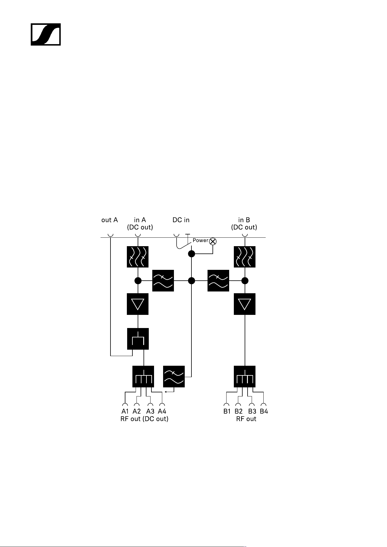
| 5 - Specifications
5 – 95 %
Operating temperature range
-10 °C – +55 °C (14 °F – 131 °F)
Storage temperature range
-20 °C – +70 °C (-4 °F – 158 °F)
Dimensions
Approx. 212 x 168 x 43 mm
Weight
Approx. 1100 g
Block diagram
559

| 5 - Specifications
EW-D AB antenna booster
Frequency ranges
• EW-D AB (Q): 470 – 550 MHz
• EW-D AB (R): 520 – 608 MHz
• EW-D AB (S): 606 – 694 MHz
• EW-D AB (T): 694 - 824 MHz
• EW-D AB (U): 823 – 865 MHz
• EW-D AB (V): 902 – 960 MHz
• EW-D AB (Y): 1785 – 1805 MHz
Power supply (DC coupled)
DC 12 V (DC 9 – 18 V) / max. 160 mA @ 12 V, center contact +
IIP3
> 25 dBm
Max. RF input power
+10 dBm
Gain
Typically 12 dB
Impedance
50 Ω
Connections
2x BNC female, DC power supply from OUT to ANT
Dimensions
Approx. 95 x 47 x 21 mm
Weight
Approx. 120 g
Relative humidity
5 – 95 %
Operating temperature range
-10 °C – +55 °C (14 °F – 131 °F)
Storage temperature range
-20 °C – +70 °C (-4 °F – 158 °F)
560

| 5 - Specifications
AWM active directional antenna
Frequency ranges
• UHF I: 470 – 694 MHz
• UHF II: 823 – 1075 MHz
• 1 G8: 1785 – 1805 MHz
Apex angle (horizontal, -3 dB)
• UHF I: not applicable
• UHF II: approx. 80°
• 1 G8: approx. 110°
Front-to-back ratio
• UHF I: not applicable
• UHF II: approx. 10 dB
• 1 G8: approx. 10 dB
Antenna gain
• UHF I: ≥ +3.0 dBi (480 MHz) | ≥ +3.5 dBi (582 MHz) | ≥ +4.5 dBi (694 MHz)
• UHF II: ≥ +6.0 dBi
• 1 G8: ≥ +6.0 dBi
Antenna polarization
Linear
Amplification (signal booster, low-noise, band-selective, +/-1 dB)
• +12 dB: Max. amplification 12 dB
• +6 dB: Max. amplification 6 dB
• 0 dB
1
: Max. amplification UHF I, UHF II: -0.5; 1 G8: -1.5
• -6 dB: Max. amplification -6 dB
1
The band-selective booster is bypassed at 0 dB. This mode requires a DC power supply.
OIP3 (@ “+12 dB”)
≥ 35 dBm
Max. RF output power
• UHF I / UHF II: approx. +22 dBm
• 1 G8: approx. +18 dBm
RF connection
BNC female, DC coupled
561

| 5 - Specifications
Impedance
50 Ω
DC connection
5.5 x 1.6 mm DC hollow jack, polarity: + inside
Power supply (via BNC or DC)
12 V DC (9 – 18 V DC) / max. 100 mA @ 12 V
LED display
ON (white = “+12 dB”; blue = “+6 dB”; green= “0 dB”; orange= “-6 dB”)
OFF (no or insufficient power supply)
Thread for tripod mounting
3/8" inside thread
Mounting holes
VESA 100 x 100
Color
Traffic white (RAL: 9016)
Housing material
Halogen-free flame-retardant PC/ABS
Dimensions
• Without wall bracket: 180 x 180 x 53 mm
• With wall bracket: 180 x 180 x 63 mm
Weight
Approx. 700 g
Operating temperature range
-10 °C to +55 °C
Storage temperature range
-20 °C to +70 °C
Relative humidity
5 to 95%
Polar diagram
Normalized to max. antenna gain
562
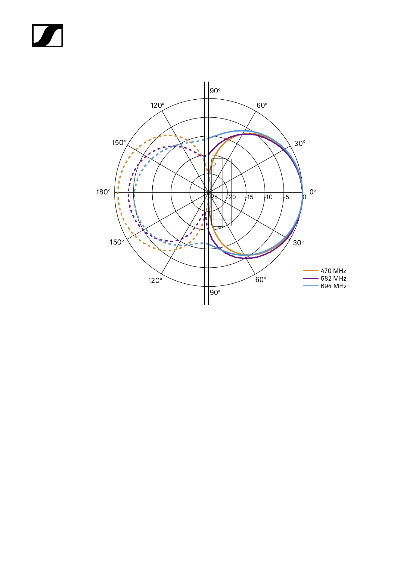
| 5 - Specifications
UHF (470 – 694 MHz) vertical [dB]
UHF (470 – 694 MHz) horizontal [dB]
563
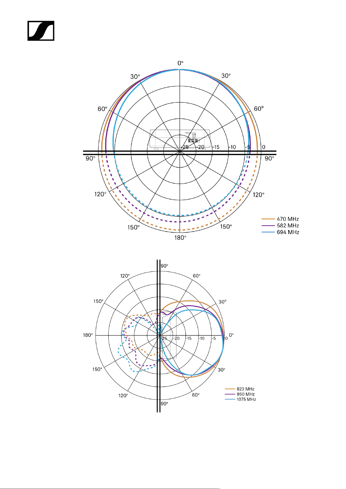
| 5 - Specifications
UHF (823 – 1075 MHz) vertical [dB]
UHF (823 – 1075 MHz) horizontal [dB]
564
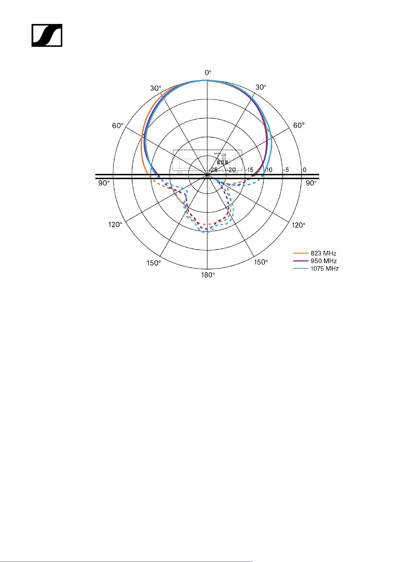
| 5 - Specifications
1G8 vertical [dB]
565
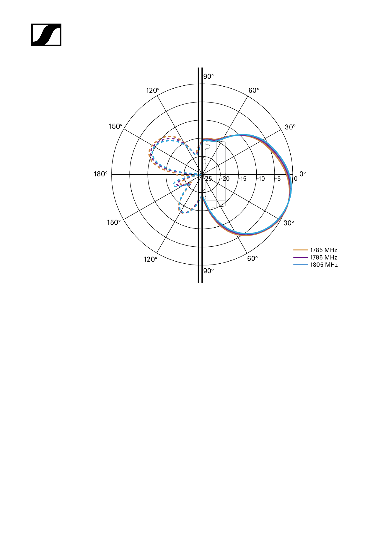
| 5 - Specifications
1G8 horizontal [dB]
566
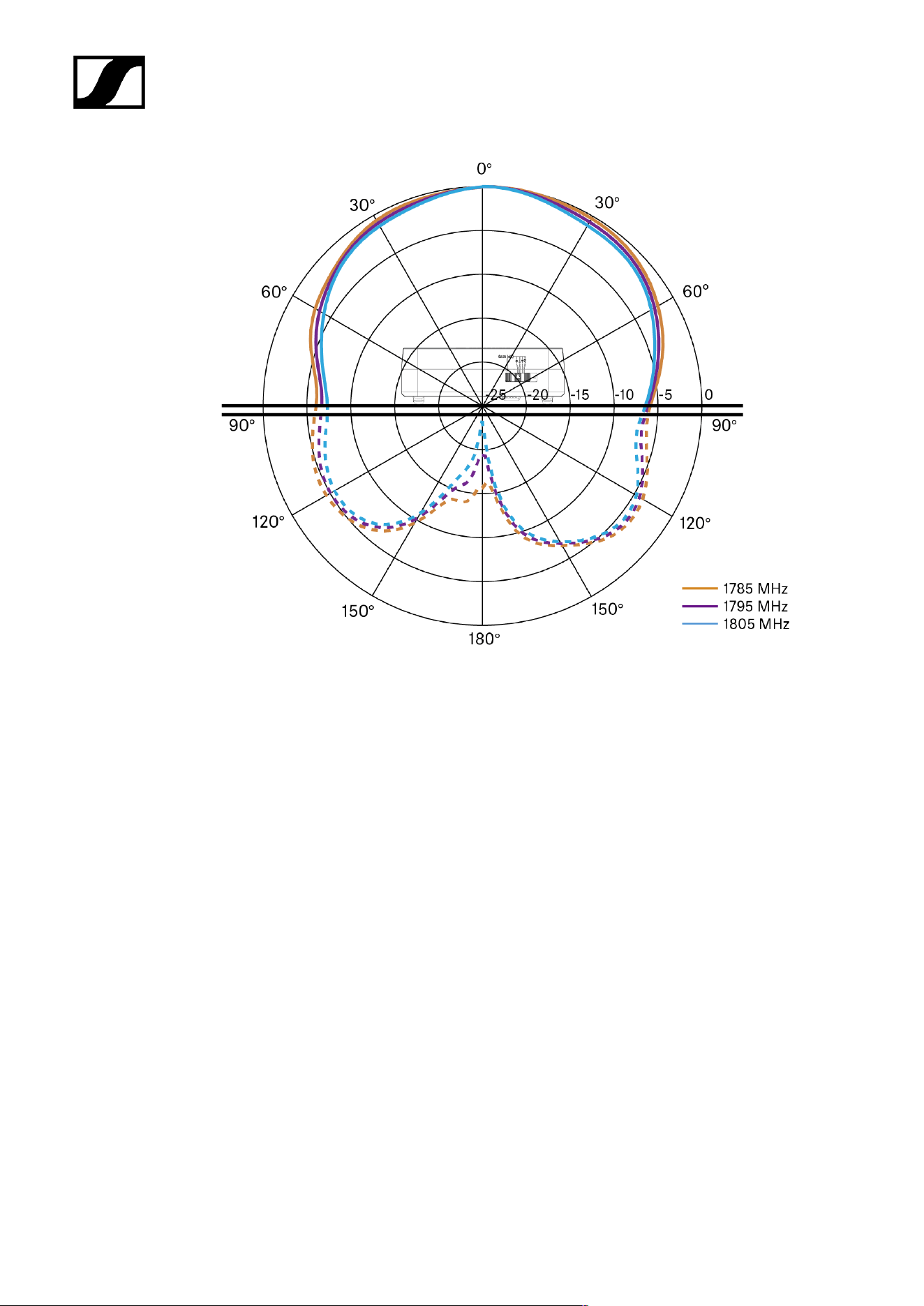
| 5 - Specifications
567

| 5 - Specifications
ADP UHF passive directional antenna (470 – 1075
MHz)
Frequency range
470 – 1075 MHz
Apex angle (-3 dB)
Approx. 100°
Front-to-back ratio
> 14 dB
Gain
Typically 5 dBi
Impedance
50 Ω
Connection
BNC female, no DC path
Thread for tripod mounting
3/8" and 5/8"
Dimensions
319 x 310 mm
Weight
Approx. 320 g
Operating temperature range
-10 °C to +55 °C
Storage temperature range
-20 °C – +85 °C (-4 °F – 158 °F)
Relative humidity
5 – 95 %
Typically Polar diagram
568
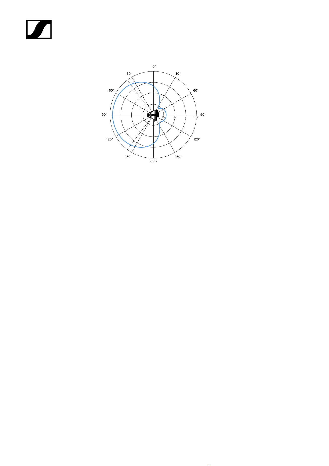
| 5 - Specifications
569

| 5 - Specifications
BA 70 rechargeable battery
Rated capacity
1720 mAh
Nominal voltage
3.8 V
Charging voltage
max. 4.35 V
Charging time
Typically 3 h @ room temperature
Dimensions
Approx. 54 x 30 x 15
Weight
Approx. 33 g
Temperature range
• Charging: 0 °C – +55 °C (32 °F – 131 °F)
• Discharging: -10 °C to +55 °C
• Storage: -10 °C to +45 °C
Relative humidity
• Charging/discharging: 25% to 95%, non-condensing
• Storage: 30% to 70%, non-condensing
570

| 5 - Specifications
L 70 USB charger
Charging capacity
2 Sennheiser BA 70 rechargeable battery packs
Input voltage
Typically 5 V
Input current
max. 2 A
Charging voltage
nominally 4.35 V
Charging current
max. 860 mA per battery pack
Charging time
max. 3.5 h with NT 5-20 UCW power supply unit
Temperature range
• Charging: 0 °C to +55 °C
• Storage: -20 °C to +70 °C
Relative humidity
Max. 95% (non-condensing)
Dimensions
100 × 35 × 70 mm (1 3/4" x 3 7/8" x 7 3/16")
Weight
Approx. 86 g
571

| 5 - Specifications
CHG 70N-C charger
Power supply
• 12 V DC (single unit or cascade of up to 5 units)
• PoE IEEE 802.3af Class 0 (CAT5e or higher), single unit only
Current consumption
max. 3.5 A for a cascade of up to 5 units
Ethernet
• RJ-45 socket, IEEE802.3
• 100Base-TX (half+full duplex)
• 10Base-T (half+full duplex)
Dimensions
Approx. 200 x 104 x 116 mm
Weight
Approx. 640 g, without power supply unit
Charging slots
2
Charging capacity per slot
• BA 70 rechargeable battery or
• EW-DX SK with BA 70 or
• EW-DX SKM with BA 70or
• SPECTERA SEK UHF/1G4
Charging voltage
4.35 V
Charging current
min. 344 mA
max. 860 mA
Full charging time
Max. 3.5 h
Temperature range
• Charging: -10 °C to +50 °C
• Storage: -20 °C to +70 °C
572

| 5 - Specifications
Relative humidity
Max. 95% (non-condensing)
573

Evolution Wireless Digital
6. Contact
Contact information in case of questions about our products and/or services.
574

Sennheiser electronic SE & Co. KG | Am Labor 1 | 30900 Wedemark | Germany
