Evolution Wireless Digital
EW-D | EW-DX | EW-DP
Sennheiser electronic GmbH & Co. KG
Am Labor 1, 30900 Wedemark, Germany, www.sennheiser.com
EW-D | EW-DX | EW-DP - v3.0 (04/2023)
Instruction manual
(PDF export of the original HTML manual)
This PDF document is a PDF export of an interactive manual in HTML format.
When displayed in PDF format, it is possible that not all content and interactive
elements in the HTML instructions are included, as these cannot be displayed in
PDF format.
We recommend using the complete and interactive HTML instructions.
You can find these in the Sennheiser Documentation App, which is available free of
charge for iOS and Android. Alternatively, the HTML instructions are also available
in the download area of the product page:
www.sennheiser.com/ew-d
www.sennheiser.com/ew-dx
www.sennheiser.com/ew-dp
Products of the EW-D series
2
Products of the EW-D series
For information about the available accessories, see „Acces-
sories“.
For information about the available sets, see „Sets available
for the EW-D series“.
For information about the frequency ranges, see „Frequency
ranges“.
You can find technical specifications for the series and the in-
dividual products under „SPECIFICATIONS“.
You can find information about starting up and operating the
products under „Starting up and operating devices of the Evo-
lution Wireless Digital series“.
Products of the EW-D series
3
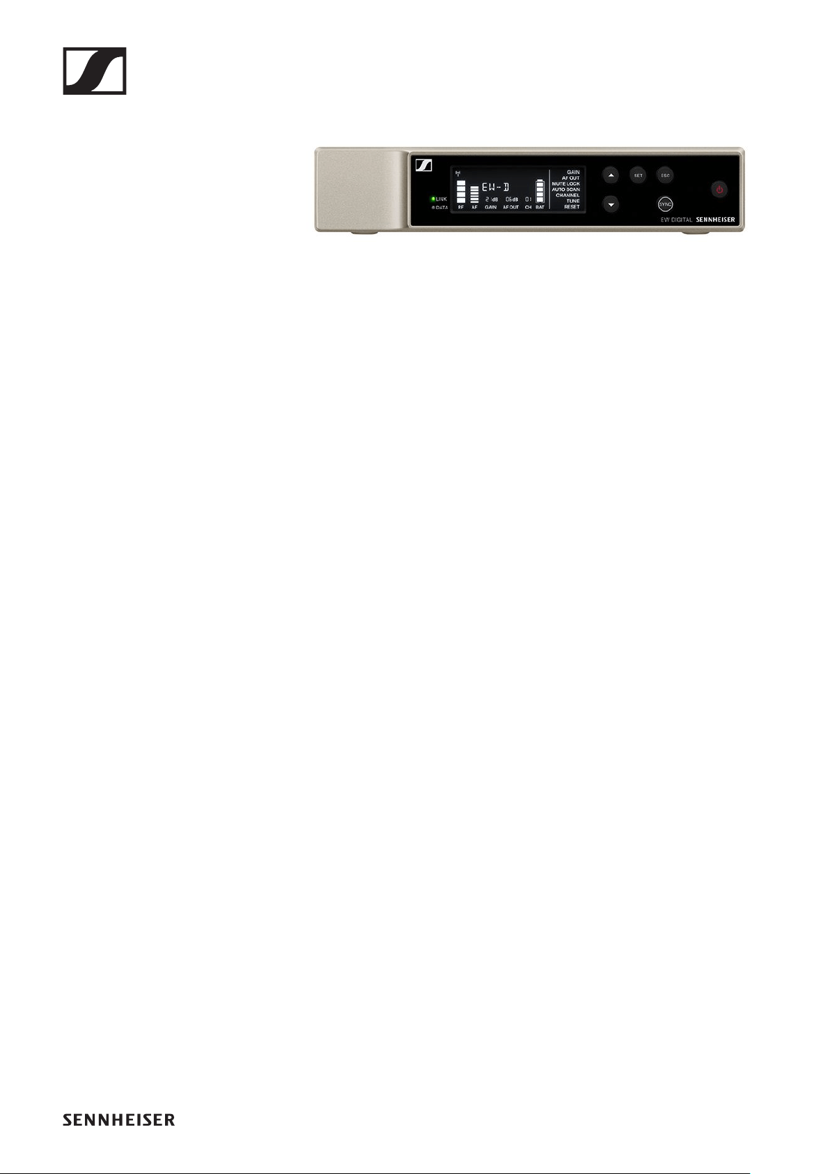
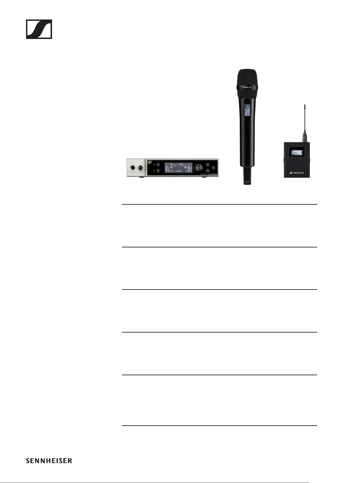
EW-D EM rack receiver
►
The EW-D EM rack receiver is available in the following ver-
sions:
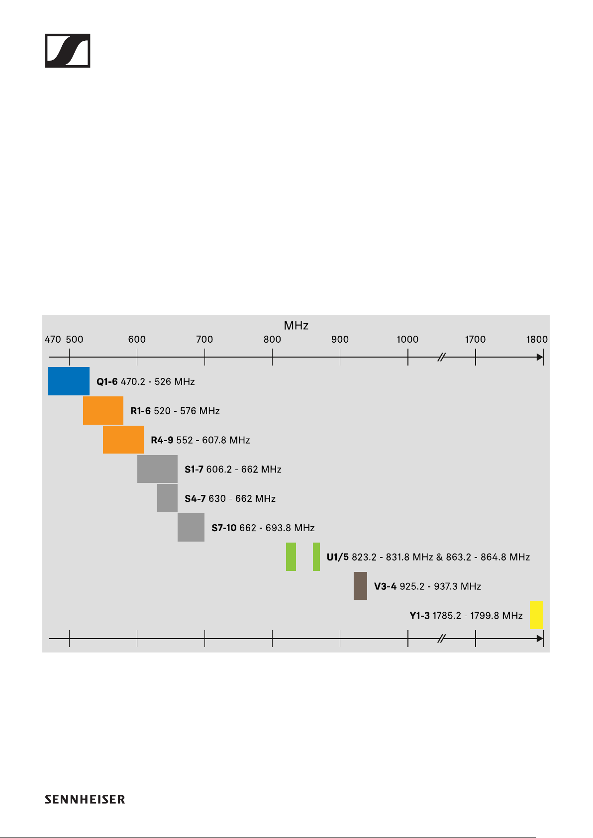
EW-D EM (Q1–6) | 470.2 – 526 MHz | Art. no. 508800
EW-D EM (R1–6) | 520 – 576 MHz | Art. no. 508801
EW-D EM (R4–9) | 552 – 607.8 MHz | Art. no. 508802
EW-D EM (S1–7) | 606.2 – 662 MHz | Art. no. 508803
EW-D EM (S4–7) | 630 – 662 MHz | Art. no. 508804
EW-D EM (S7–10) | 662 – 693.8 MHz | Art. no. 508805
EW-D EM (U1/5) | 823.2 – 831.8 MHz & 863.2 – 864.8 MHz | Art.
no. 508806
EW-D EM (V3–4) | 925.2 – 937.3 MHz | Art. no. 508808
EW-D EM (Y1–3) | 1785.2 – 1799.8 MHz | Art. no. 508809
You can find more detailed information about the EW-D EM in
the following sections:
▷Startup and operation: „EW-D EM rack receiver“
▷Specifications: „EW-D EM rack receiver“
Products of the EW-D series
4
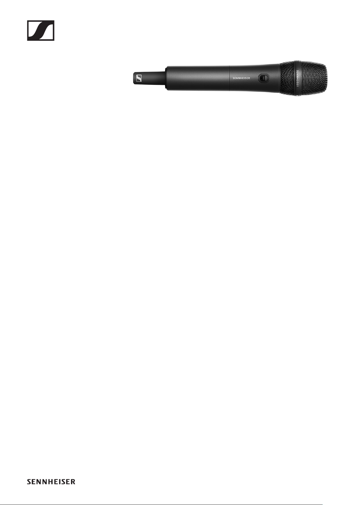
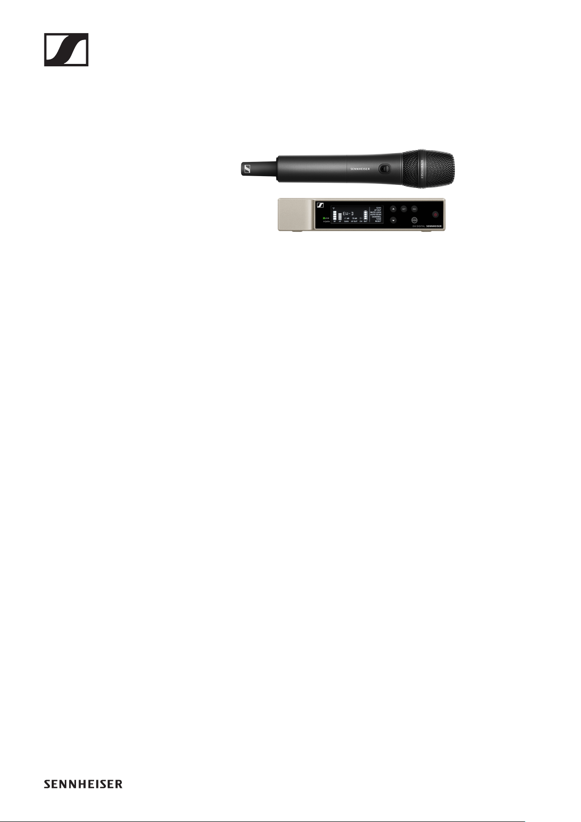
EW-D SKM-S handheld transmitter
►
The EW-D SKM-S handheld transmitter is available in the fol-
lowing versions:
EW-D SKM-S (Q1–6) | 470.2 – 526 MHz | Art. no. 508790
EW-D SKM-S (R1–6) | 520 – 576 MHz | Art. no. 508791
EW-D SKM-S (R4–9) | 552 – 607.8 MHz | Art. no. 508792
EW-D SKM-S (S1–7) | 606.2 – 662 MHz | Art. no. 508793
EW-D SKM-S (S4–7) | 630 – 662 MHz | Art. no. 508794
EW-D SKM-S (S7–10) | 662 – 693.8 MHz | Art. no. 508795
EW-D SKM-S (U1/5) | 823.2 – 831.8 MHz & 863.2 – 864.8 MHz
| Art. no. 508796
EW-D SKM-S (V3–4) | 925.2 – 937.3 MHz | Art. no. 508798
EW-D SKM-S (Y1–3) | 1785.2 – 1799.8 MHz | Art. no. 508799
You can find more detailed information about the EW-D SKM-
S in the following sections:
▷Startup and operation: „EW-D SKM-S handheld transmit-
ter“
▷Specifications: „EW-D SKM-S handheld transmitter“
▷Compatible microphone modules: „Replacing the micro-
phone module“
Products of the EW-D series
5
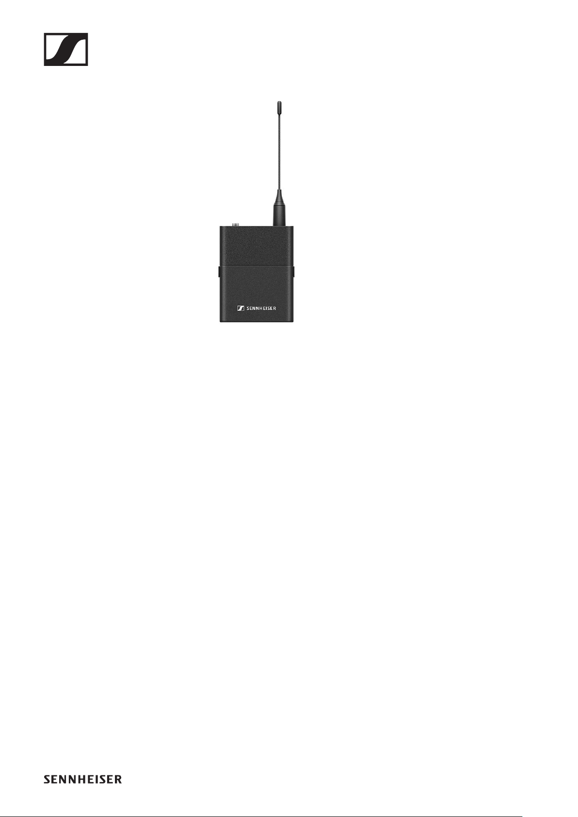
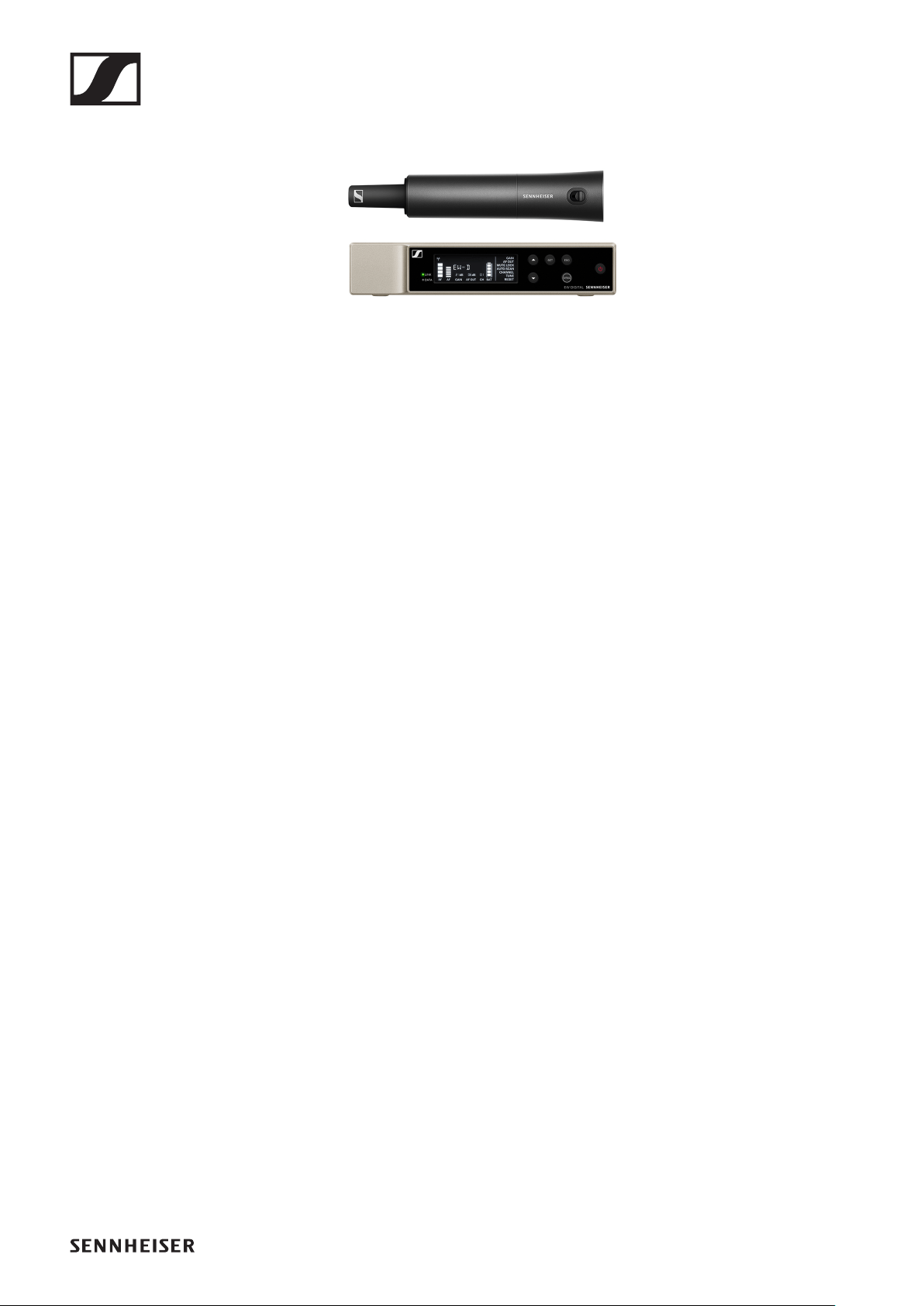
EW-D SK bodypack transmitter
►
The EW-D SK bodypack transmitter is available in the follow-
ing versions:
EW-D SK (Q1–6) | 470.2 – 526 MHz | Art. no. 508780
EW-D SK (R1–6) | 520 – 576 MHz | Art. no. 508781
EW-D SK (R4–9) | 552 – 607.8 MHz | Art. no. 508782
EW-D SK (S1–7) | 606.2 – 662 MHz | Art. no. 508783
EW-D SK (S4–7) | 630 – 662 MHz | Art. no. 508784
EW-D SK (S7–10) | 662 – 693.8 MHz | Art. no. 508785
EW-D SK (U1/5) | 823.2 – 831.8 MHz & 863.2 – 864.8 MHz | Art.
no. 508786
EW-D SKM-S (V3–4) | 925.2 – 937.3 MHz | Art. no. 508788
EW-D SKM-S (Y1–3) | 1785.2 – 1799.8 MHz | Art. no. 508789
You can find more detailed information about the EW-D SK in
the following sections:
▷Startup and operation: „EW-D SK bodypack transmitter“
▷Specifications: „EW-D SK bodypack transmitter“
▷Compatible microphones: „Connecting a microphone to
the bodypack transmitter“
Sets available for the EW-D series
6
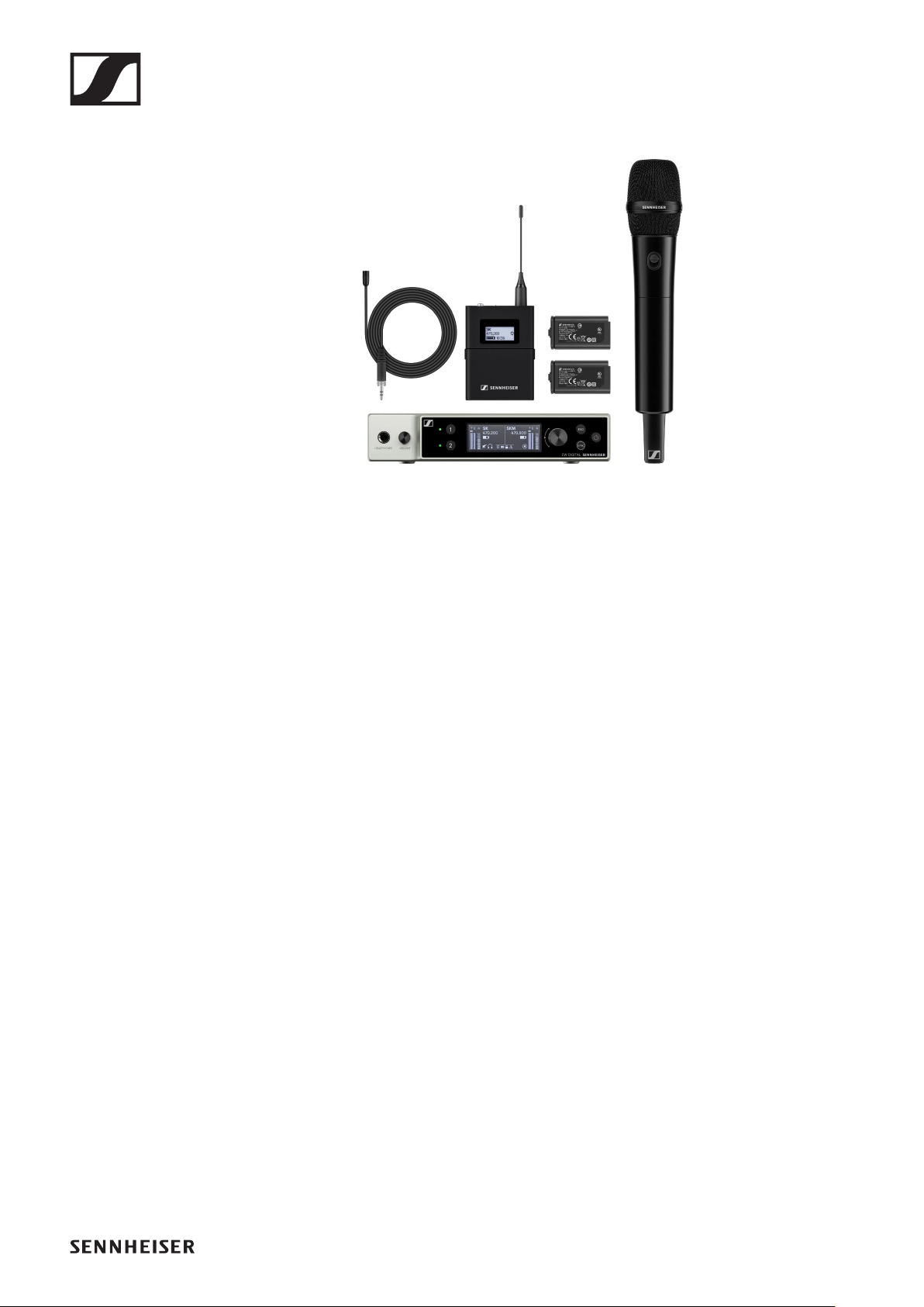
Sets available for the EW-D series
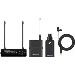
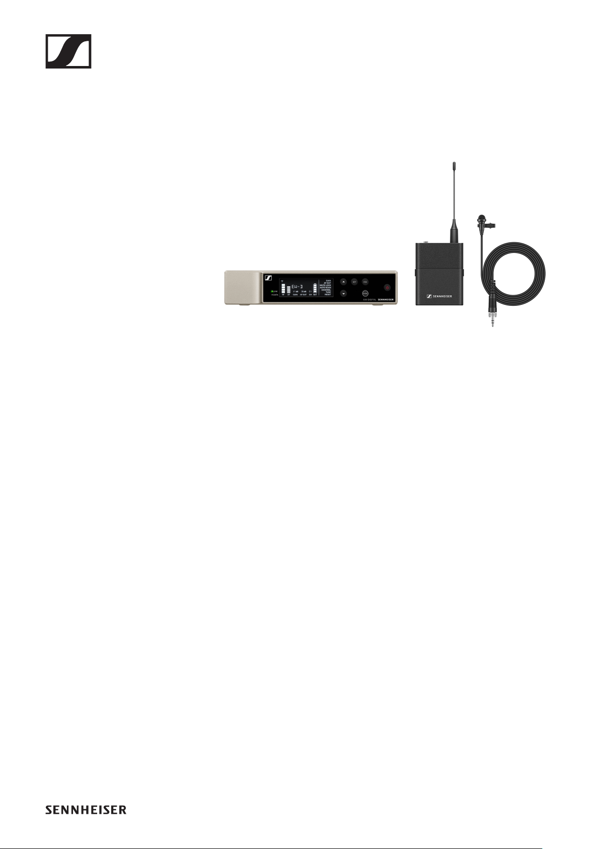
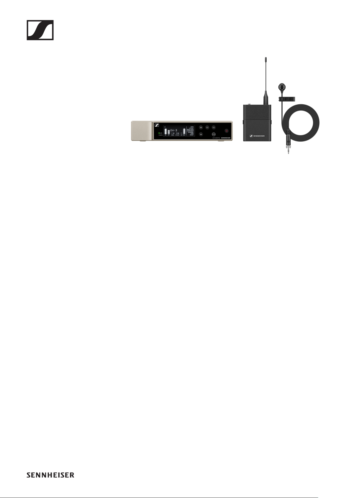
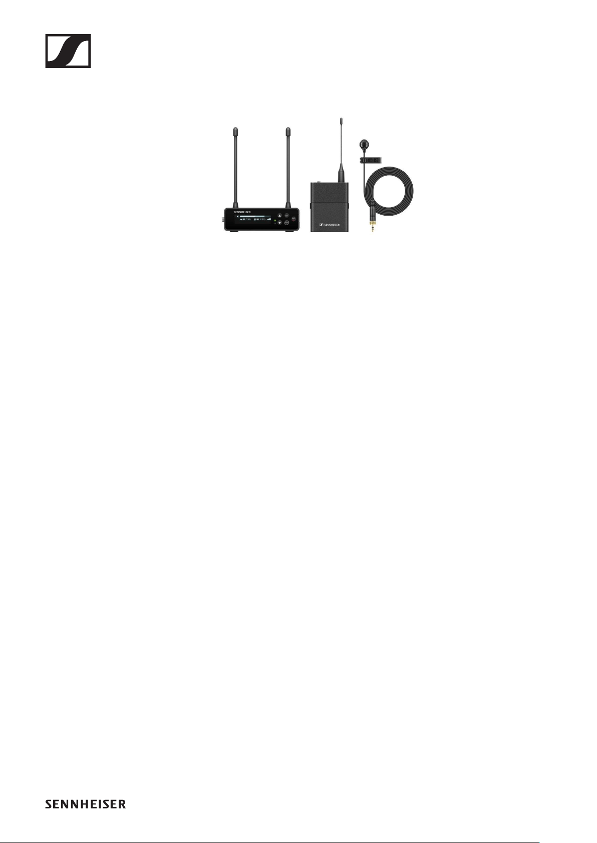
EW-D ME2 SET | Lavalier Set
►
The set consists of the following components:
•EW-D EM rack receiver
•EW-D SK bodypack transmitter
•ME 2 lavalier microphone
The set is available in the following versions:
EW-D ME2 SET (Q1–6) | 470.2 – 526 MHz | Art. no. 508700
EW-D ME2 SET (R1–6) | 520 – 576 MHz | Art. no. 508701
EW-D ME2 SET (R4–9) | 552 – 607.8 MHz | Art. no. 508702
EW-D ME2 SET (S1–7) | 606.2 – 662 MHz | Art. no. 508703
EW-D ME2 SET (S4–7) | 630 – 662 MHz | Art. no. 508704
EW-D ME2 SET (S7–10) | 662 – 693.8 MHz | Art. no. 508705
EW-D ME2 SET (U1/5) | 823.2 – 831.8 MHz & 863.2 – 864.8
MHz | Art. no. 508706
EW-D ME2 SET (V3–4) | 925.2 – 937.3 MHz | Art. no. 508708
EW-D ME2 SET (Y1–3) | 1785.2 – 1799.8 MHz | Art. no. 508709
You can find more detailed information about the set in the fol-
lowing sections:
▷Startup and operation: „Starting up and operating devices
of the Evolution Wireless Digital series“
▷Specifications: „SPECIFICATIONS“
Sets available for the EW-D series
7
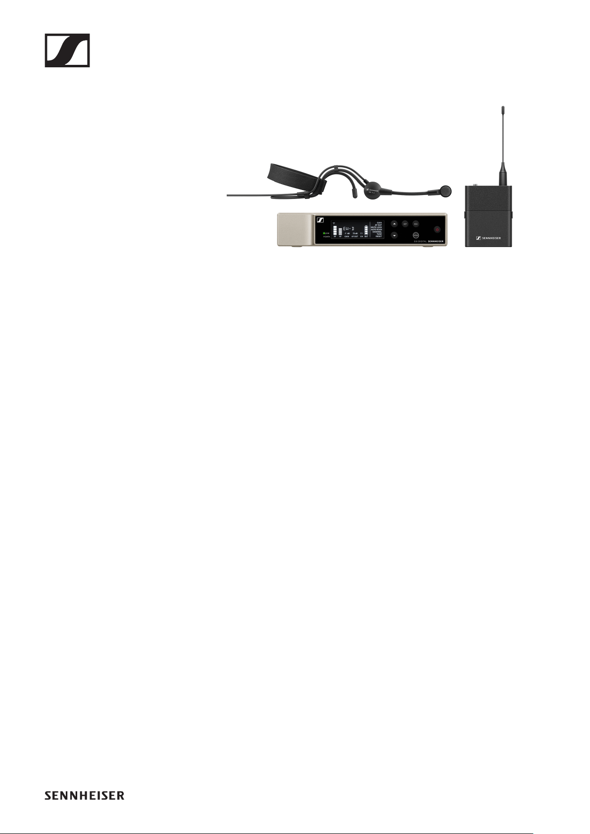
EW-D ME3 SET | Headmic Set
►
The set consists of the following components:
•EW-D EM rack receiver
•EW-D SK bodypack transmitter
•ME 3 headset microphone
The set is available in the following versions:
EW-D ME3 SET (Q1–6) | 470.2 – 526 MHz | Art. no. 508710
EW-D ME3 SET (R1–6) | 520 – 576 MHz | Art. no. 508711
EW-D ME3 SET (R4–9) | 552 – 607.8 MHz | Art. no. 508712
EW-D ME3 SET (S1–7) | 606.2 – 662 MHz | Art. no. 508713
EW-D ME3 SET (S4–7) | 630 – 662 MHz | Art. no. 508714
EW-D ME3 SET (S7–10) | 662 – 693.8 MHz | Art. no. 508715
EW-D ME3 SET (U1/5) | 823.2 – 831.8 MHz & 863.2 – 864.8
MHz | Art. no. 508716
EW-D ME3 SET (V3–4) | 925.2 – 937.3 MHz | Art. no. 508718
EW-D ME3 SET (Y1–3) | 1785.2 – 1799.8 MHz | Art. no. 508719
You can find more detailed information about the set in the fol-
lowing sections:
▷Startup and operation: „Starting up and operating devices
of the Evolution Wireless Digital series“
▷Specifications: „SPECIFICATIONS“
Sets available for the EW-D series
8
EW-D ME4 SET | Lavalier Set
►
The set consists of the following components:
•EW-D EM rack receiver
•EW-D SK bodypack transmitter
•ME 4 lavalier microphone
The set is available in the following versions:
EW-D ME4 SET (Q1–6) | 470.2 – 526 MHz | Art. no. 508720
EW-D ME4 SET (R1–6) | 520 – 576 MHz | Art. no. 508721
EW-D ME4 SET (R4–9) | 552 – 607.8 MHz | Art. no. 508722
EW-D ME4 SET (S1–7) | 606.2 – 662 MHz | Art. no. 508723
EW-D ME4 SET (S4–7) | 630 – 662 MHz | Art. no. 508724
EW-D ME4 SET (S7–10) | 662 – 693.8 MHz | Art. no. 508725
EW-D ME4 SET (U1/5) | 823.2 – 831.8 MHz & 863.2 – 864.8
MHz | Art. no. 508726
EW-D ME4 SET (V3–4) | 925.2 – 937.3 MHz | Art. no. 508728
EW-D ME4 SET (Y1–3) | 1785.2 – 1799.8 MHz | Art. no. 508729
You can find more detailed information about the set in the fol-
lowing sections:
▷Startup and operation: „Starting up and operating devices
of the Evolution Wireless Digital series“
▷Specifications: „SPECIFICATIONS“
Sets available for the EW-D series
9
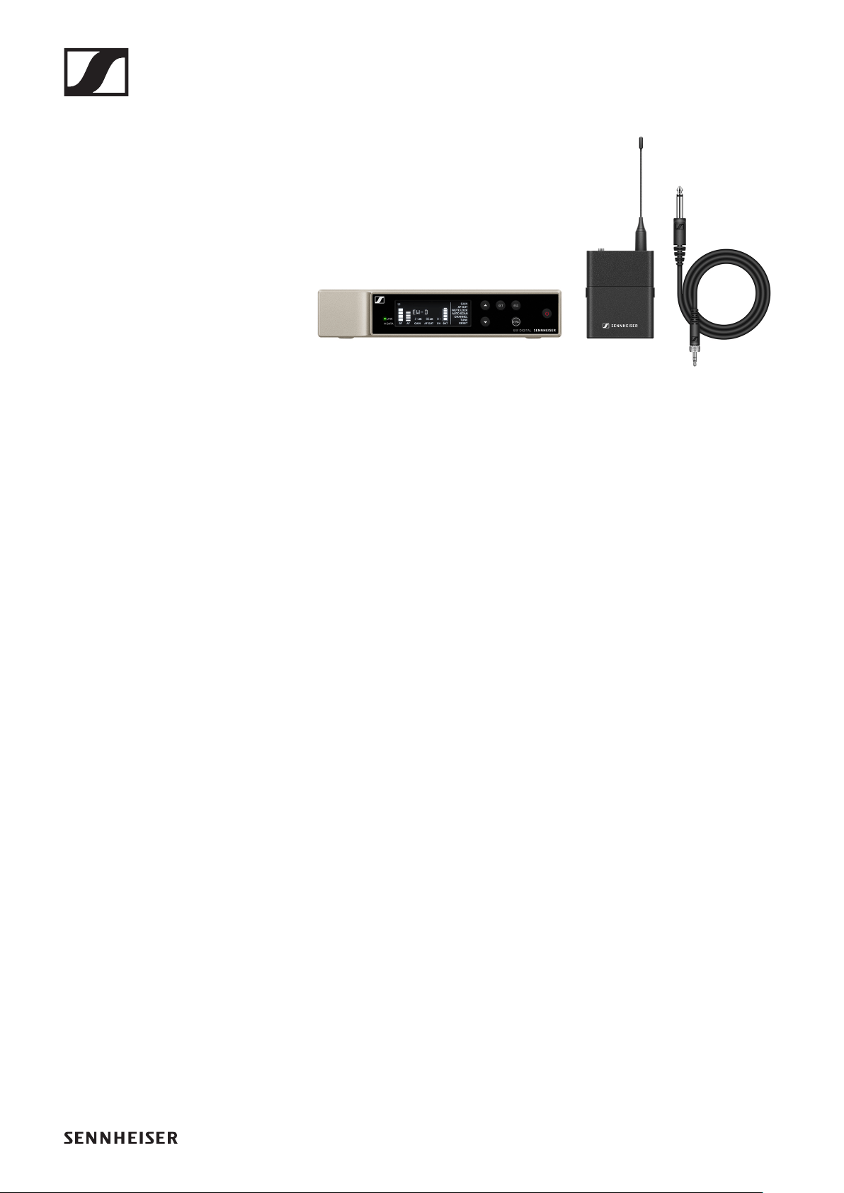
EW-D CI1 SET | Instrument Set
►
The set consists of the following components:
•EW-D EM rack receiver
•EW-D SK bodypack transmitter
•CI 1 instrument cable
The set is available in the following versions:
EW-D CI1 SET (Q1–6) | 470.2 – 526 MHz | Art. no. 508730
EW-D CI1 SET (R1–6) | 520 – 576 MHz | Art. no. 508731
EW-D CI1 SET (R4–9) | 552 – 607.8 MHz | Art. no. 508732
EW-D CI1 SET (S1–7) | 606.2 – 662 MHz | Art. no. 508733
EW-D CI1 SET (S4–7) | 630 – 662 MHz | Art. no. 508734
EW-D CI1 SET (S7–10) | 662 – 693.8 MHz | Art. no. 508735
EW-D CI1 SET (U1/5) | 823.2 – 831.8 MHz & 863.2 – 864.8 MHz
| Art. no. 508736
EW-D CI1 SET (V3–4) | 925.2 – 937.3 MHz | Art. no. 508738
EW-D CI1 SET (Y1–3) | 1785.2 – 1799.8 MHz | Art. no. 508739
You can find more detailed information about the set in the fol-
lowing sections:
▷Startup and operation: „Starting up and operating devices
of the Evolution Wireless Digital series“
▷Specifications: „SPECIFICATIONS“
Sets available for the EW-D series
10
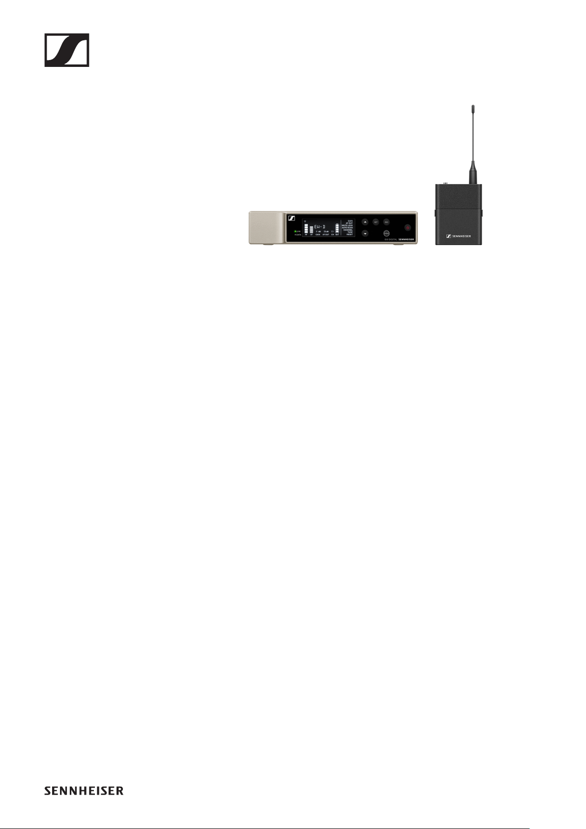
EW-D SK BASE SET | Base Set
►
The set consists of the following components:
•EW-D EM rack receiver
•EW-D SK bodypack transmitter
The set is available in the following versions:
EW-D SK BASE SET (Q1–6) | 470.2 – 526 MHz | Art. no. 508740
EW-D SK BASE SET (R1–6) | 520 – 576 MHz | Art. no. 508741
EW-D SK BASE SET (R4–9) | 552 – 607.8 MHz | Art. no. 508742
EW-D SK BASE SET (S1–7) | 606.2 – 662 MHz | Art. no. 508743
EW-D SK BASE SET (S4–7) | 630 – 662 MHz | Art. no. 508744
EW-D SK BASE SET (S7–10) | 662 – 693.8 MHz | Art. no.
508745
EW-D SK BASE SET (U1/5) | 823.2 – 831.8 MHz & 863.2 – 864.8
MHz | Art. no. 508746
EW-D SK BASE SET (V3–4) | 925.2 – 937.3 MHz | Art. no.
508748
EW-D SK BASE SET (Y1–3) | 1785.2 – 1799.8 MHz | Art. no.
508749
You can find more detailed information about the set in the fol-
lowing sections:
▷Startup and operation: „Starting up and operating devices
of the Evolution Wireless Digital series“
▷Specifications: „SPECIFICATIONS“
Sets available for the EW-D series
11
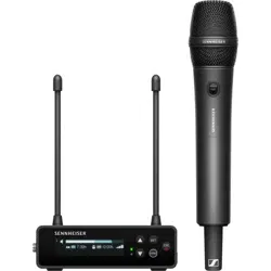
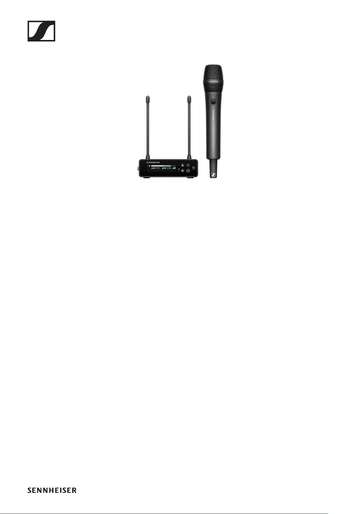
EW-D 835-S SET | Handheld Set
►
The set consists of the following components:
•EW-D EM rack receiver
•EW-D SKM-S handheld transmitter
•MMD 835 microphone module
The set is available in the following versions:
EW-D 835-S SET (Q1–6) | 470.2 – 526 MHz | Art. no. 508750
EW-D 835-S SET (R1–6) | 520 – 576 MHz | Art. no. 508751
EW-D 835-S SET (R4–9) | 552 – 607.8 MHz | Art. no. 508752
EW-D 835-S SET (S1–7) | 606.2 – 662 MHz | Art. no. 508753
EW-D 835-S SET (S4–7) | 630 – 662 MHz | Art. no. 508754
EW-D 835-S SET (S7–10) | 662 – 693.8 MHz | Art. no. 508755
EW-D 835-S SET (U1/5) | 823.2 – 831.8 MHz & 863.2 – 864.8
MHz | Art. no. 508756
EW-D 835-S SET (V3–4) | 925.2 – 937.3 MHz | Art. no. 508758
EW-D 835-S SET (Y1–3) | 1785.2 – 1799.8 MHz | Art. no. 508759
You can find more detailed information about the set in the fol-
lowing sections:
▷Startup and operation: „Starting up and operating devices
of the Evolution Wireless Digital series“
▷Specifications: „SPECIFICATIONS“
Sets available for the EW-D series
12
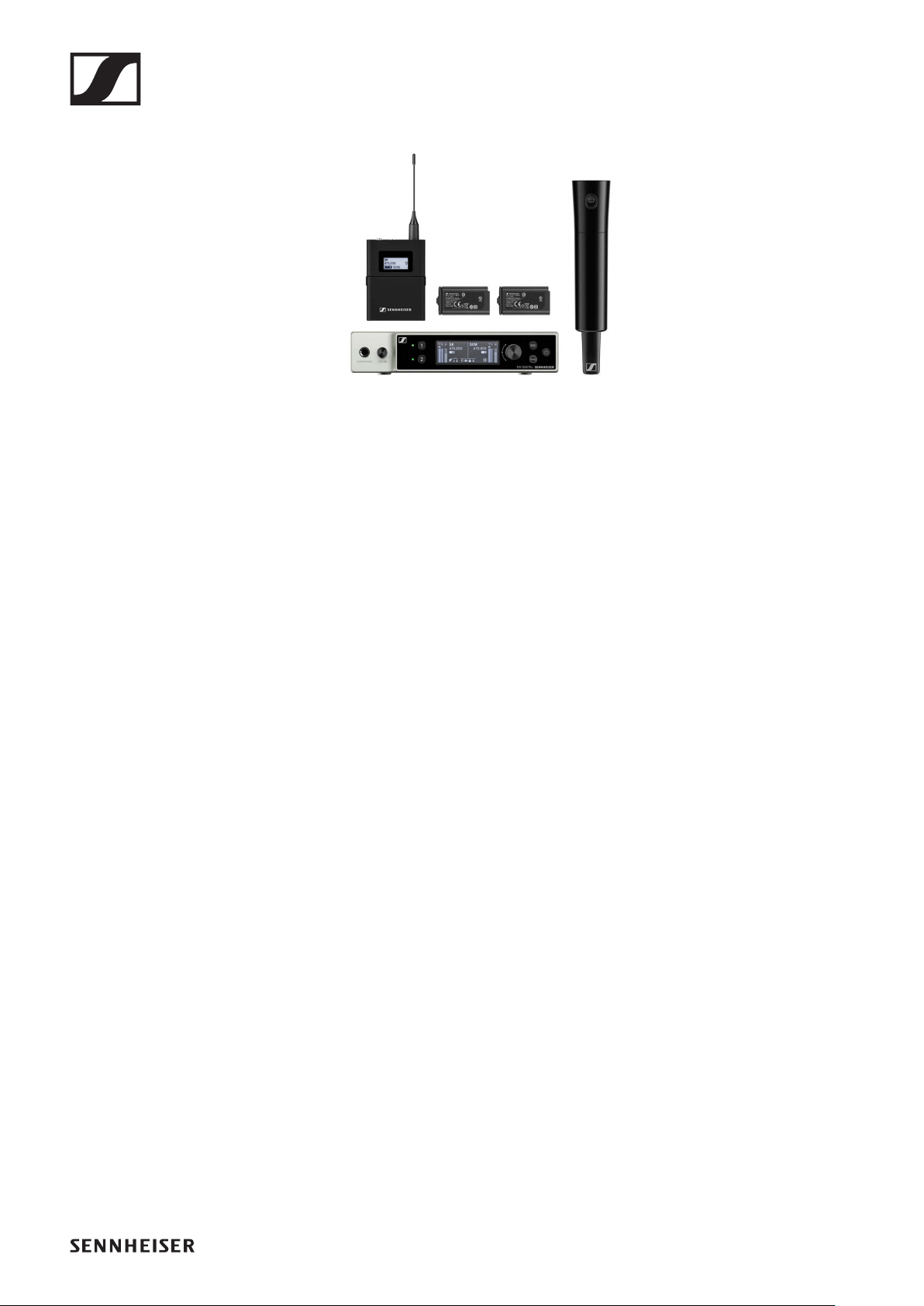
EW-D SKM-S BASE SET | Base Set
►
The set consists of the following components:
•EW-D EM rack receiver
•EW-D SKM-S handheld transmitter
The set is available in the following versions:
EW-D SKM-S BASE SET (Q1–6) | 470.2 – 526 MHz | Art. no.
508760
EW-D SKM-S BASE SET (R1–6) | 520 – 576 MHz | Art. no.
508761
EW-D SKM-S BASE SET (R4–9) | 552 – 607.8 MHz | Art. no.
508762
EW-D SKM-S BASE SET (S1–7) | 606.2 – 662 MHz | Art. no.
508763
EW-D SKM-S BASE SET (S4–7) | 630 – 662 MHz | Art. no.
508764
EW-D SKM-S BASE SET (S7–10) | 662 – 693.8 MHz | Art. no.
508765
EW-D SKM-S BASE SET (U1/5) | 823.2 – 831.8 MHz & 863.2 –
864.8 MHz | Art. no. 508766
EW-D SKM-S BASE SET (V3–4) | 925.2 – 937.3 MHz | Art. no.
508768
EW-D SKM-S BASE SET (Y1–3) | 1785.2 – 1799.8 MHz | Art. no.
508769
You can find more detailed information about the set in the fol-
lowing sections:
▷Startup and operation: „Starting up and operating devices
of the Evolution Wireless Digital series“
▷Specifications: „SPECIFICATIONS“

Sets available for the EW-D series
13
EW-D ME2/835-S SET | Combo Set
►
The set consists of the following components:
•EW-D EM rack receiver
•EW-D SK bodypack transmitter
•EW-D SKM-S handheld transmitter
•ME 2 lavalier microphone
•MMD 835 microphone module
The set is available in the following versions:
EW-D ME2/835-S SET (Q1–6) | 470.2 – 526 MHz | Art. no.
508770
EW-D ME2/835-S SET (R1–6) | 520 – 576 MHz | Art. no. 508771
EW-D ME2/835-S SET (R4–9) | 552 – 607.8 MHz | Art. no.
508772
EW-D ME2/835-S SET (S1–7) | 606.2 – 662 MHz | Art. no.
508773
EW-D ME2/835-S SET (S4–7) | 630 – 662 MHz | Art. no.
508774
EW-D ME2/835-S SET (S7–10) | 662 – 693.8 MHz | Art. no.
508775
EW-D ME2/835-S SET (U1/5) | 823.2 – 831.8 MHz & 863.2 –
864.8 MHz | Art. no. 508776
EW-D ME2/835-S SET (V3–4) | 925.2 – 937.3 MHz | Art. no.
508778
EW-D ME2/835-S SET (Y1–3) | 1785.2 – 1799.8 MHz | Art. no.
508779
You can find more detailed information about the set in the fol-
lowing sections:
▷Startup and operation: „Starting up and operating devices
of the Evolution Wireless Digital series“
▷Specifications: „SPECIFICATIONS“
Products of the EW-DX series
14
Products of the EW-DX series
For information about the available accessories, see „Acces-
sories“.
For information about the available sets, see „Sets available
for the EW-DX series“.
For information about the frequency ranges, see „Frequency
ranges“.
You can find technical specifications for the series and the in-
dividual products under „SPECIFICATIONS“.
You can find information about starting up and operating the
products under „Starting up and operating devices of the Evo-
lution Wireless Digital series“.
Products of the EW-DX series
15
EW-DX EM 2 rack receiver
►
The EW-DX EM 2 rack receiver is available in the following
versions:
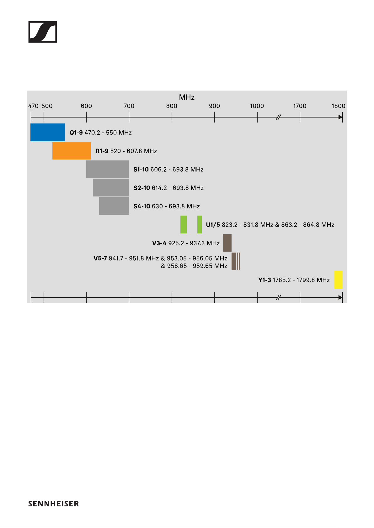
EW-DX EM 2 (Q1–9) | 470.2 – 550 MHz | Art. no. 509342
EW-DX EM 2 (R1–9) | 520 – 607.8 MHz | Art. no. 509343
EW-DX EM 2 (S1–10) | 606.2 – 693.8 MHz | Art. no. 509344
EW-DX EM 2 (S2–10) | 614.2 – 693.8 MHz | Art. no. 509347
EW-DX EM 2 (S4–10) | 630 – 693.8 MHz | Art. no. 509348
EW-DX EM 2 (U1/5) | 823.2 – 831.8 MHz & 863.2 – 864.8 MHz
| Art. no. 509349
EW-DX EM 2 (V3–4) | 925.2 – 937.3 MHz | Art. no. 509351
EW-DX EM 2 (V5–7) | 941.7 – 951.8 MHz & 953.05 – 956.05
MHz & 956.65 – 959.65 MHz | Art. no. 509352
EW-DX EM 2 (Y1–3) | 1785.2 – 1799.8 MHz | Art. no. 509355
You can find more detailed information about the EW-DX EM 2
in the following sections:
▷Startup and operation: „EW-DX EM 2 rack receiver“
▷Specifications: „EW-DX EM 2 rack receiver“
Products of the EW-DX series
16
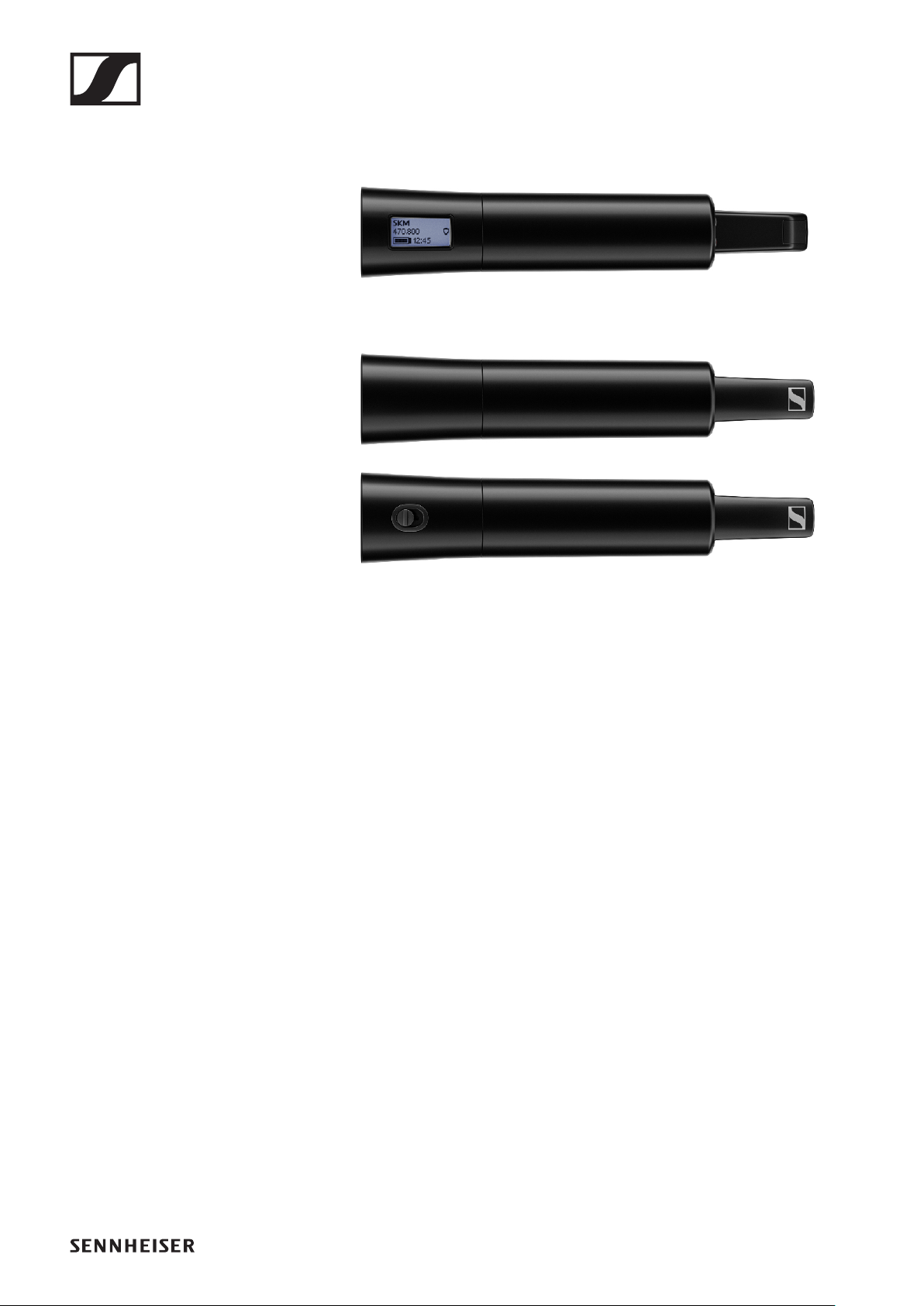
EW-DX SKM | EW-DX SKM-S handheld trans-
mitter
►
The EW-DX SKM handheld transmitter without mute switch is
available in the following versions:
EW-DX SKM (Q1–9) | 470.2 – 550 MHz | Art. no. 509426
EW-DX SKM (R1–9) | 520 – 607.8 MHz | Art. no. 509427
EW-DX SKM (S1–10) | 606.2 – 693.8 MHz | Art. no. 509428
EW-DX SKM (S2–10) | 614.2 – 693.8 MHz | Art. no. 509431
EW-DX SKM (S4–10) | 630 – 693.8 MHz | Art. no. 509432
EW-DX SKM (U1/5) | 823.2 – 831.8 MHz & 863.2 – 864.8 MHz |
Art. no. 509433
EW-DX SKM (V3–4) | 925.2 – 937.3 MHz | Art. no. 509435
EW-DX SKM (V5–7) | 941.7 – 951.8 MHz & 953.05 – 956.05
MHz & 956.65 – 959.65 MHz | Art. no. 509436
EW-DX SKM (Y1–3) | 1785.2 – 1799.8 MHz | Art. no. 509439
The EW-DX SKM-S handheld transmitter with mute switch is
available in the following versions:
EW-DX SKM-S (Q1–9) | 470.2 – 550 MHz | Art. no. 509412
EW-DX SKM-S (R1–9) | 520 – 607.8 MHz | Art. no. 509413
EW-DX SKM-S (S1–10) | 606.2 – 693.8 MHz | Art. no. 509414

Products of the EW-DX series
17
EW-DX SKM-S (S2–10) | 614.2 – 693.8 MHz | Art. no. 509417
EW-DX SKM-S (S4–10) | 630 – 693.8 MHz | Art. no. 509418
EW-DX SKM-S (U1/5) | 823.2 – 831.8 MHz & 863.2 – 864.8 MHz
| Art. no. 509419
EW-DX SKM-S (V3–4) | 925.2 – 937.3 MHz | Art. no. 509421
EW-DX SKM-S (V5–7) | 941.7 – 951.8 MHz & 953.05 – 956.05
MHz & 956.65 – 959.65 MHz | Art. no. 509422
EW-DX SKM-S (Y1–3) | 1785.2 – 1799.8 MHz | Art. no. 509423
You can find more detailed information about the EW-DX SKM
and EW-DX SKM-S in the following sections:
▷Startup and operation: „EW-DX SKM | EW-DX SKM-S
handheld transmitter“
▷Specifications: „EW-DX SKM | EW-DX SKM-S handheld
transmitter“
▷Compatible microphone modules: „Replacing the micro-
phone module“
Products of the EW-DX series
18
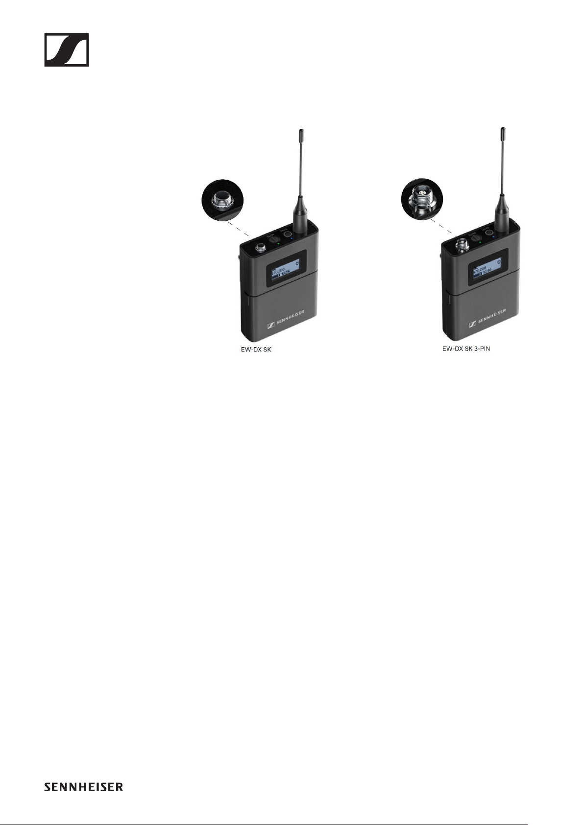
EW-DX SK | EW-DX SK 3-PIN bodypack trans-
mitter
►
The EW-DX SK bodypack transmitter is available in the follow-
ing versions:
EW-DX SK (Q1–9) | 470.2 – 550 MHz | Art. no. 509384
EW-DX SK (R1–9) | 520 – 607.8 MHz | Art. no. 509385
EW-DX SK (S1–10) | 606.2 – 693.8 MHz | Art. no. 509386
EW-DX SK (S2–10) | 614.2 – 693.8 MHz | Art. no. 509389
EW-DX SK (S4–10) | 630 – 693.8 MHz | Art. no. 509390
EW-DX SK (U1/5) | 823.2 – 831.8 MHz & 863.2 – 864.8 MHz |
Art. no. 509391
EW-DX SK (V3–4) | 925.2 – 937.3 MHz | Art. no. 509393
EW-DX SK (V5–7) | 941.7 – 951.8 MHz & 953.05 – 956.05 MHz
& 956.65 – 959.65 MHz | Art. no. 509394
EW-DX SK (Y1–3) | 1785.2 – 1799.8 MHz | Art. no. 509397
The EW-DX SK 3-PIN bodypack transmitter is available in the
following versions:
EW-DX SK 3-PIN (Q1–9) | 470.2 – 550 MHz | Art. no. 509398
EW-DX SK 3-PIN (R1–9) | 520 – 607.8 MHz | Art. no. 509399
EW-DX SK 3-PIN (S1–10) | 606.2 – 693.8 MHz | Art. no. 509400

Products of the EW-DX series
19
EW-DX SK 3-PIN (S2–10) | 614.2 – 693.8 MHz | Art. no. 509403
EW-DX SK 3-PIN (S4–10) | 630 – 693.8 MHz | Art. no. 509404
EW-DX SK 3-PIN (U1/5) | 823.2 – 831.8 MHz & 863.2 – 864.8
MHz | Art. no. 509405
EW-DX SK 3-PIN (V3–4) | 925.2 – 937.3 MHz | Art. no. 509407
EW-DX SK 3-PIN (V5–7) | 941.7 – 951.8 MHz & 953.05 – 956.05
MHz & 956.65 – 959.65 MHz | Art. no. 509408
EW-DX SK 3-PIN (Y1–3) | 1785.2 – 1799.8 MHz | Art. no. 509411
You can find more detailed information about the EW-DX SK
and EW-DX SK 3-PIN in the following sections:
▷Startup and operation: „EW-DX SK | EW-DX SK 3-PIN
bodypack transmitter“
▷Specifications: „EW-DX SK | EW-DX SK 3-PIN bodypack
transmitter“
▷Compatible microphones: „Connecting a microphone to
the bodypack transmitter“
Sets available for the EW-DX series
20
Sets available for the EW-DX series
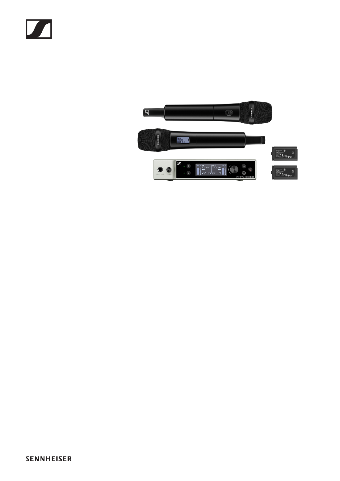
EW-DX 835-S SET | Handheld Set
►
The set consists of the following components:
•EW-DX EM 2 rack receiver
•2x EW-DX SKM-S handheld transmitters
•2x MMD 835 microphone modules
•2x BA 70 rechargeable batteries
The set is available in the following versions:
EW-DX 835-S SET (Q1–9) | 470.2 – 550 MHz | Art. no. 509300
EW-DX 835-S SET (R1–9) | 520 – 607.8 MHz | Art. no. 509301
EW-DX 835-S SET (S1–10) | 606.2 – 693.8 MHz | Art. no.
509302
EW-DX 835-S SET (S2–10) | 614.2 – 693.8 MHz | Art. no.
509305
EW-DX 835-S SET (S4–10) | 630 – 693.8 MHz | Art. no. 509306
EW-DX 835-S SET (U1/5) | 823.2 – 831.8 MHz & 863.2 – 864.8
MHz | Art. no. 509307
EW-DX 835-S SET (V3–4) | 925.2 – 937.3 MHz | Art. no.
509309
EW-DX 835-S SET (V5–7) | 941.7 – 951.8 MHz & 953.05 –
956.05 MHz & 956.65 – 959.65 MHz | Art. no. 509310
EW-DX 835-S SET (Y1–3) | 1785.2 – 1799.8 MHz | Art. no.
509313
You can find more detailed information about the set in the fol-
lowing sections:
▷Startup and operation: „Starting up and operating devices
of the Evolution Wireless Digital series“
▷Specifications: „SPECIFICATIONS“
Sets available for the EW-DX series
21
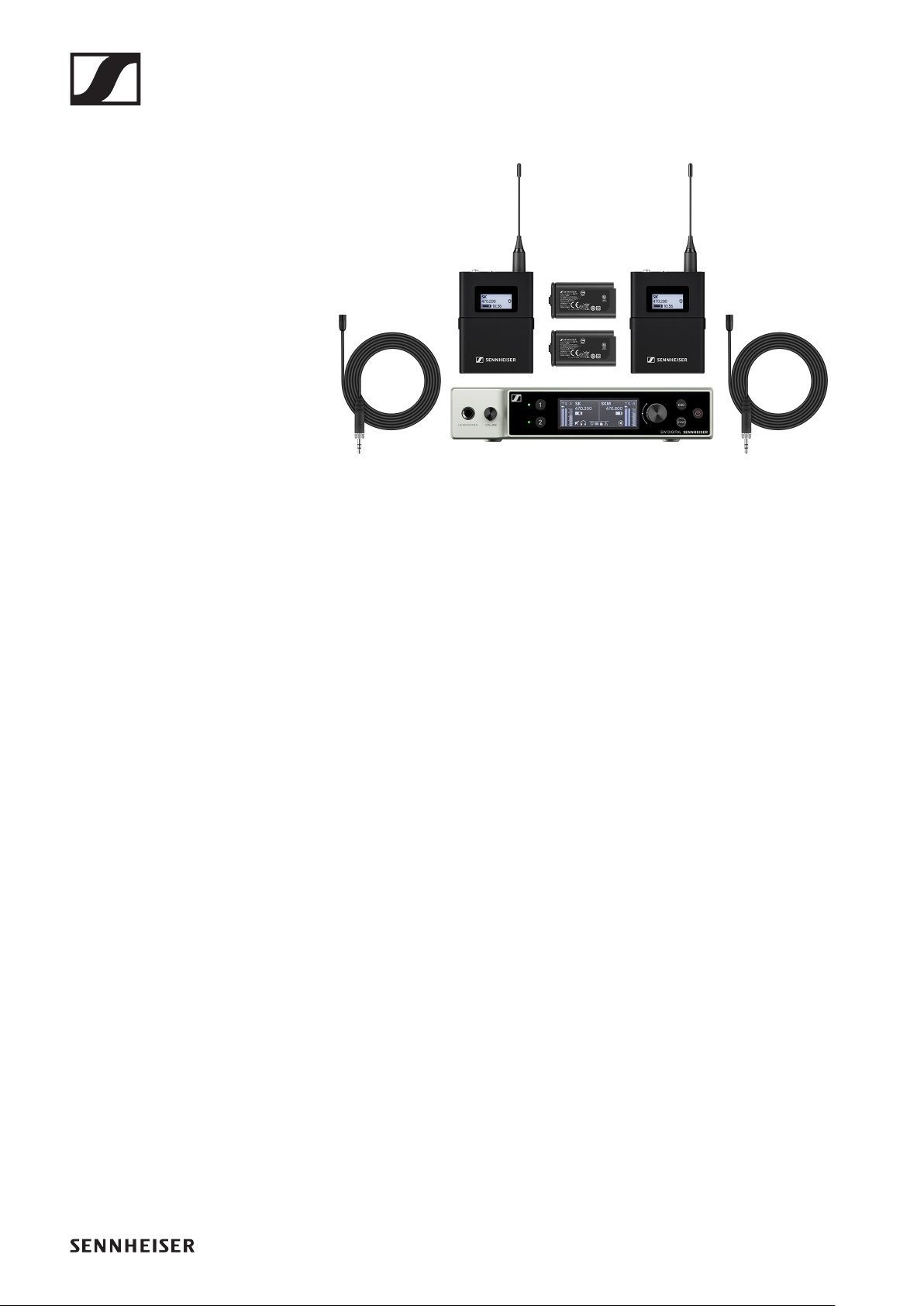
EW-DX MKE 2 SET | Lavalier Set
►
The set consists of the following components:
•EW-DX EM 2 rack receiver
•2x EW-DX SK bodypack transmitters
•2x MKE 2 lavalier microphones
•2x BA 70 rechargeable batteries
The set is available in the following versions:
EW-DX MKE 2 SET (Q1–9) | 470.2 – 550 MHz | Art. no. 509314
EW-DX MKE 2 SET (R1–9) | 520 – 607.8 MHz | Art. no. 509315
EW-DX MKE 2 SET (S1–10) | 606.2 – 693.8 MHz | Art. no.
509316
EW-DX MKE 2 SET (S2–10) | 614.2 – 693.8 MHz | Art. no.
509319
EW-DX MKE 2 SET (S4–10) | 630 – 693.8 MHz | Art. no. 509320
EW-DX MKE 2 SET (U1/5) | 823.2 – 831.8 MHz & 863.2 – 864.8
MHz | Art. no. 509321
EW-DX MKE 2 SET (V3–4) | 925.2 – 937.3 MHz | Art. no.
509323
EW-DX MKE 2 SET (V5–7) | 941.7 – 951.8 MHz & 953.05 –
956.05 MHz & 956.65 – 959.65 MHz | Art. no. 509324
EW-DX MKE 2 SET (Y1–3) | 1785.2 – 1799.8 MHz | Art. no.
509327
You can find more detailed information about the set in the fol-
lowing sections:
▷Startup and operation: „Starting up and operating devices
of the Evolution Wireless Digital series“
▷Specifications: „SPECIFICATIONS“
Sets available for the EW-DX series
22
EW-DX MKE 2-835-S SET | Combo Set
►
The set consists of the following components:
•EW-DX EM 2 rack receiver
•1x EW-DX SK bodypack transmitters
•1x MKE 2 lavalier microphones
•1x EW-DX SKM-S handheld transmitters
•1x MMD 835 microphone modules
•2x BA 70 rechargeable batteries
The set is available in the following versions:
EW-DX MKE 2-835-S SET (Q1–9) | 470.2 – 550 MHz |
Art. no. 509328
EW-DX MKE 2-835-S SET (R1–9) | 520 – 607.8 MHz |
Art. no. 509329
EW-DX MKE 2-835-S SET (S1–10) | 606.2 – 693.8 MHz |
Art. no. 509330
EW-DX MKE 2-835-S SET (S2–10) | 614.2 – 693.8 MHz |
Art. no. 509333
EW-DX MKE 2-835-S SET (S4–10) | 630 – 693.8 MHz |
Art. no. 509334
EW-DX MKE 2-835-S SET (U1/5) |
823.2 – 831.8 MHz & 863.2 – 864.8 MHz | Art. no. 509335
EW-DX MKE 2-835-S SET (V3–4) | 925.2 – 937.3 MHz |
Art. no. 509337
EW-DX MKE 2-835-S SET (V5–7) | 941.7 – 951.8 MHz & 953.05
– 956.05 MHz & 956.65 – 959.65 MHz | Art. no. 509338
EW-DX MKE 2-835-S SET (Y1–3) | 1785.2 – 1799.8 MHz |
Art. no. 509341

Sets available for the EW-DX series
24
EW-DX SK-SKM-S BASE SET | Base Set
►
The set consists of the following components:
•EW-DX EM 2 rack receiver
•1x EW-DX SK bodypack transmitters
•1x EW-DX SKM-S handheld transmitters
•2x BA 70 rechargeable batteries
The set is available in the following versions:
EW-DX SK-SKM-S BASE SET (Q1–9) | 470.2 – 550 MHz |
Art. no. 509462
EW-DX SK-SKM-S BASE SET (R1–9) | 520 – 607.8 MHz |
Art. no. 509463
EW-DX SK-SKM-S BASE SET (S1–10) | 606.2 – 693.8 MHz |
Art. no. 509464
EW-DX SK-SKM-S BASE SET (S2–10) | 614.2 – 693.8 MHz |
Art. no. 509467
EW-DX SK-SKM-S BASE SET (S4–10) | 630 – 693.8 MHz |
Art. no. 509468
EW-DX SK-SKM-S BASE SET (U1/5) |
823.2 – 831.8 MHz & 863.2 – 864.8 MHz | Art. no. 509469
EW-DX SK-SKM-S BASE SET (V3–4) | 925.2 – 937.3 MHz |
Art. no. 509471
EW-DX SK-SKM-S BASE SET (V5–7) | 941.7 – 951.8 MHz &
953.05 – 956.05 MHz & 956.65 – 959.65 MHz | Art. no. 509472
EW-DX SK-SKM-S BASE SET (Y1–3) | 1785.2 – 1799.8 MHz |
Art. no. 509475
You can find more detailed information about the set in the fol-
lowing sections:
▷Startup and operation: „Starting up and operating devices
of the Evolution Wireless Digital series“
▷Specifications: „SPECIFICATIONS“
Products of the EW-DP series
25
Products of the EW-DP series
For information about the available accessories, see „Acces-
sories“.
For information about the available sets, see „Sets available
for the EW-DP series“.
For information about the frequency ranges, see „Frequency
ranges“.
You can find technical specifications for the series and the in-
dividual products under „SPECIFICATIONS“.
You can find information about starting up and operating the
products under „Starting up and operating devices of the Evo-
lution Wireless Digital series“.
Products of the EW-DP series
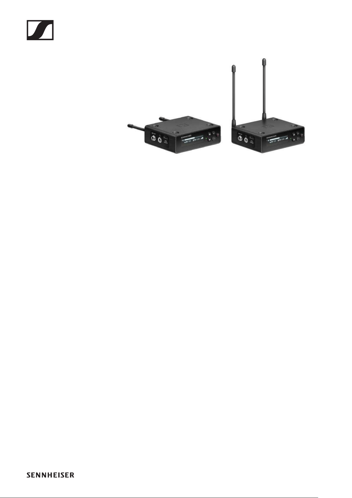
26
EW-DP EK portable receiver
►
The EW-DP EK rack receiver is available in the following ver-
sions:
EW-DP EK (Q1–6) | 470.2 – 526 MHz | Art. no. 700050
EW-DP EK (R1–6) | 520 – 576 MHz | Art. no. 700051
EW-DP EK (R4–9) | 552 – 607.8 MHz | Art. no. 700052
EW-DP EK (S1–7) | 606.2 – 662 MHz | Art. no. 700053
EW-DP EK (S4–7) | 630 – 662 MHz | Art. no. 700054
EW-DP EK (S7–10) | 662 – 693.8 MHz | Art. no. 700055
EW-DP EK (U1/5) | 823.2 – 831.8 MHz & 863.2 – 864.8 MHz |
Art. no. 700056
EW-DP EK (V3–4) | 925.2 – 937.3 MHz | Art. no. 700058
EW-DP EK (Y1–3) | 1785.2 – 1799.8 MHz | Art. no. 700059
You can find more detailed information about the EW-DP EK in
the following sections:
▷Startup and operation: „EW-DP EK portable receiver“
▷Specifications: „EW-DP EK portable receiver“

Sets available for the EW-DP series
27
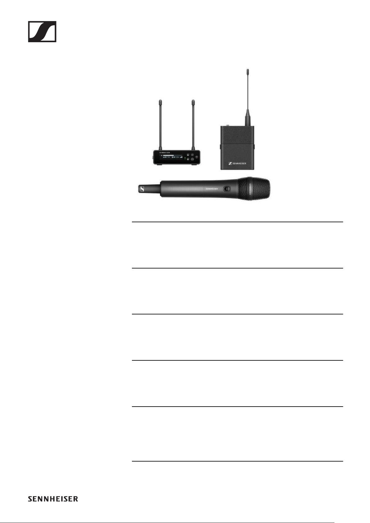
Sets available for the EW-DP series
EW-DP ME-2 | Lavalier Set
►
The set consists of the following components:
•EW-DP EK portable receiver
•EW-DP SK bodypack transmitter
•ME 2 lavalier microphone
The set is available in the following versions:
EW-DP ME-2 SET (Q1–6) | 470.2 – 526 MHz | Art. no. 700010
EW-DP ME-2 SET (R1–6) | 520 – 576 MHz | Art. no. 700011
EW-DP ME-2 SET (R4–9) | 552 – 607.8 MHz | Art. no. 700012
EW-DP ME-2 SET (S1–7) | 606.2 – 662 MHz | Art. no. 700013
EW-DP ME-2 SET (S4–7) | 630 – 662 MHz | Art. no. 700014
EW-DP ME-2 SET (S7–10) | 662 – 693.8 MHz | Art. no. 700015
EW-DP ME-2 SET (U1/5) | 823.2 – 831.8 MHz & 863.2 – 864.8
MHz | Art. no. 700016
EW-DP ME-2 SET (V3–4) | 925.2 – 937.3 MHz | Art. no. 700018
EW-DP ME-2 SET (Y1–3) | 1785.2 – 1799.8 MHz | Art. no. 700019
You can find more detailed information about the set in the fol-
lowing sections:
▷Startup and operation: „Starting up and operating devices
of the Evolution Wireless Digital series“
▷Specifications: „SPECIFICATIONS“
Sets available for the EW-DP series
28
EW-DP ME-4 | Lavalier Set
►
The set consists of the following components:
•EW-DP EK portable receiver
•EW-DP SK bodypack transmitter
•ME 4 lavalier microphone
The set is available in the following versions:
EW-DP ME-4 SET (Q1–6) | 470.2 – 526 MHz | Art. no. 700020
EW-DP ME-4 SET (R1–6) | 520 – 576 MHz | Art. no. 700021
EW-DP ME-4 SET (R4–9) | 552 – 607.8 MHz | Art. no. 700022
EW-DP ME-4 SET (S1–7) | 606.2 – 662 MHz | Art. no. 700023
EW-DP ME-4 SET (S4–7) | 630 – 662 MHz | Art. no. 700024
EW-DP ME-4 SET (S7–10) | 662 – 693.8 MHz | Art. no. 700025
EW-DP ME-4 SET (U1/5) | 823.2 – 831.8 MHz & 863.2 – 864.8
MHz | Art. no. 700026
EW-DP ME-4 SET (V3–4) | 925.2 – 937.3 MHz | Art. no. 700028
EW-DP ME-4 SET (Y1–3) | 1785.2 – 1799.8 MHz | Art. no.
700029
You can find more detailed information about the set in the fol-
lowing sections:
▷Startup and operation: „Starting up and operating devices
of the Evolution Wireless Digital series“
▷Specifications: „SPECIFICATIONS“
Sets available for the EW-DP series
29
EW-DP 835 | Handheld Set
►
The set consists of the following components:
•EW-DP EK portable receiver
•EW-D SKM handheld transmitter
•MMD 835 microphone module
The set is available in the following versions:
EW-DP 835 SET (Q1–6) | 470.2 – 526 MHz | Art. no. 700030
EW-DP 835 SET (R1–6) | 520 – 576 MHz | Art. no. 700031
EW-DP 835 SET (R4–9) | 552 – 607.8 MHz | Art. no. 700032
EW-DP 835 SET (S1–7) | 606.2 – 662 MHz | Art. no. 700033
EW-DP 835 SET (S4–7) | 630 – 662 MHz | Art. no. 700034
EW-DP 835 SET (S7–10) | 662 – 693.8 MHz | Art. no. 700035
EW-DP 835 SET (U1/5) | 823.2 – 831.8 MHz & 863.2 – 864.8
MHz | Art. no. 700036
EW-DP 835 SET (V3–4) | 925.2 – 937.3 MHz | Art. no. 700038
EW-DP 835 SET (Y1–3) | 1785.2 – 1799.8 MHz | Art. no. 700039
You can find more detailed information about the set in the fol-
lowing sections:
▷Startup and operation: „Starting up and operating devices
of the Evolution Wireless Digital series“
▷Specifications: „SPECIFICATIONS“
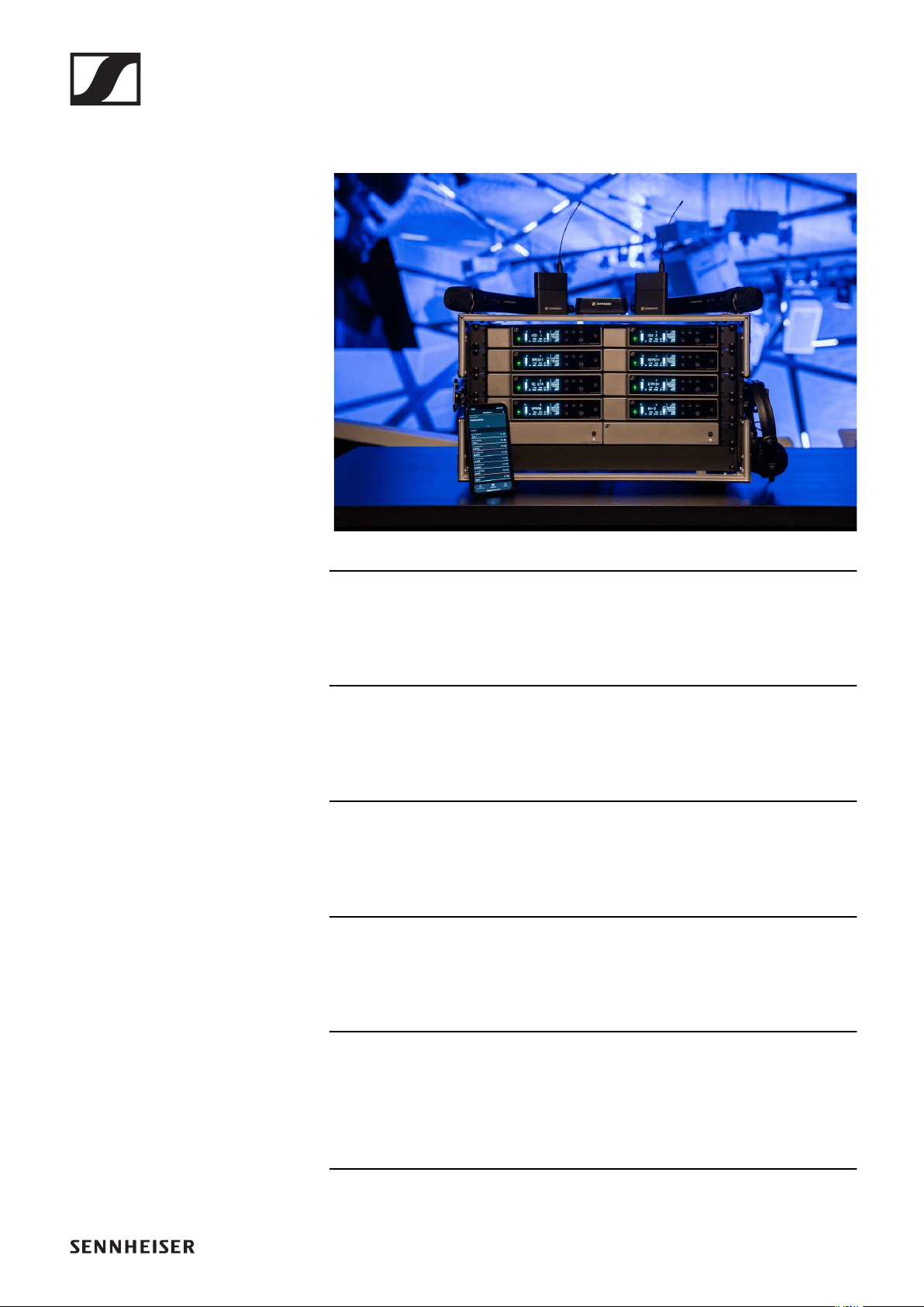
EW-D Smart Assist app
30
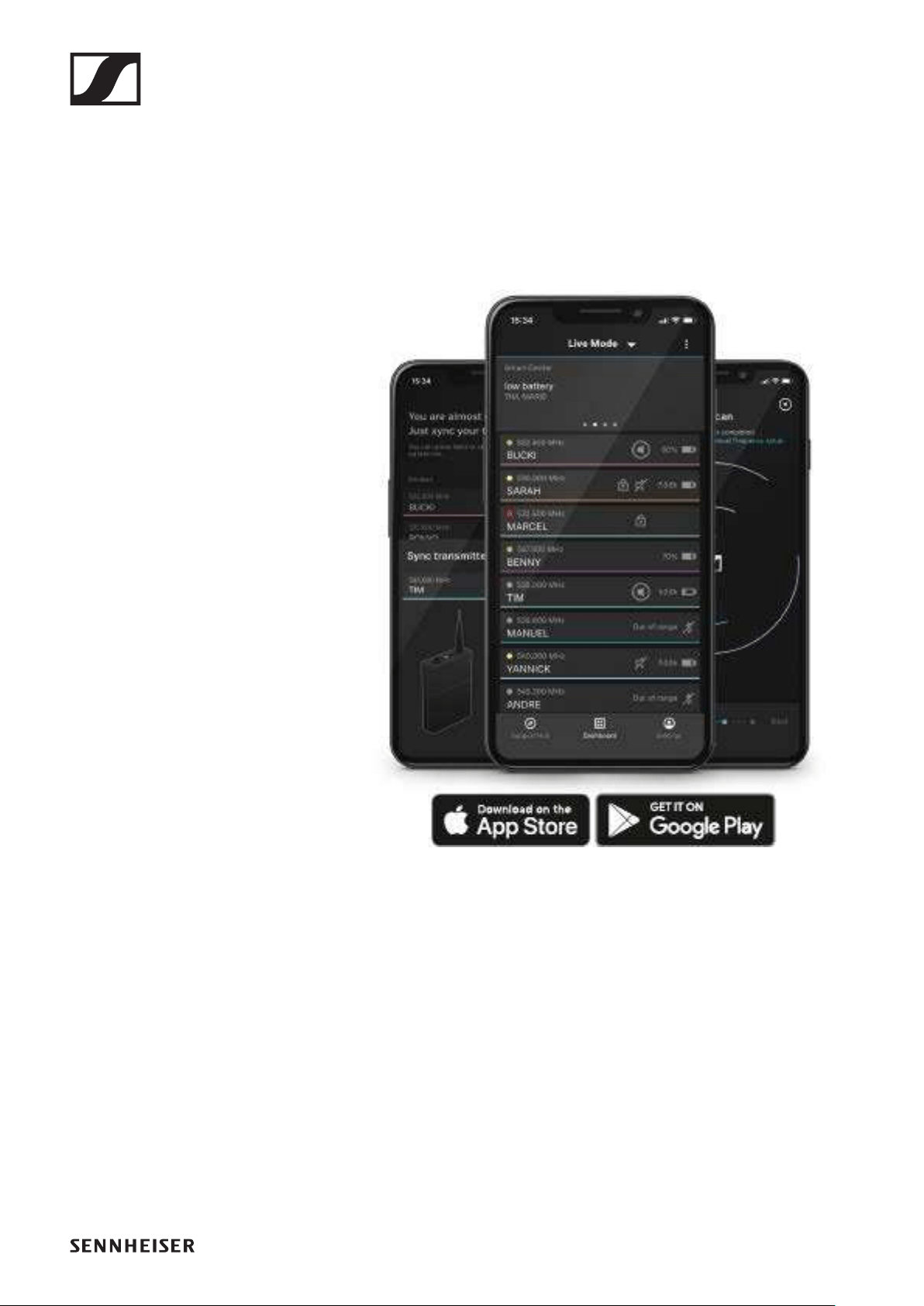
EW-D Smart Assist app
You can operate your products easily and intuitively using the
EW-D Smart Assist app for iOS and Android.
You can make all device settings in the app, as well as use oth-
er functions that are not available on the devices themselves.
The app offers you the following benefits:
▷Use all products easily and intuitively
▷Update the firmware of all devices
▷Easily configure multi-channel systems with automatic fre-
quency setup
▷Assign names and color labels to wireless links
▷Get tips and support
Accessories
31
Accessories
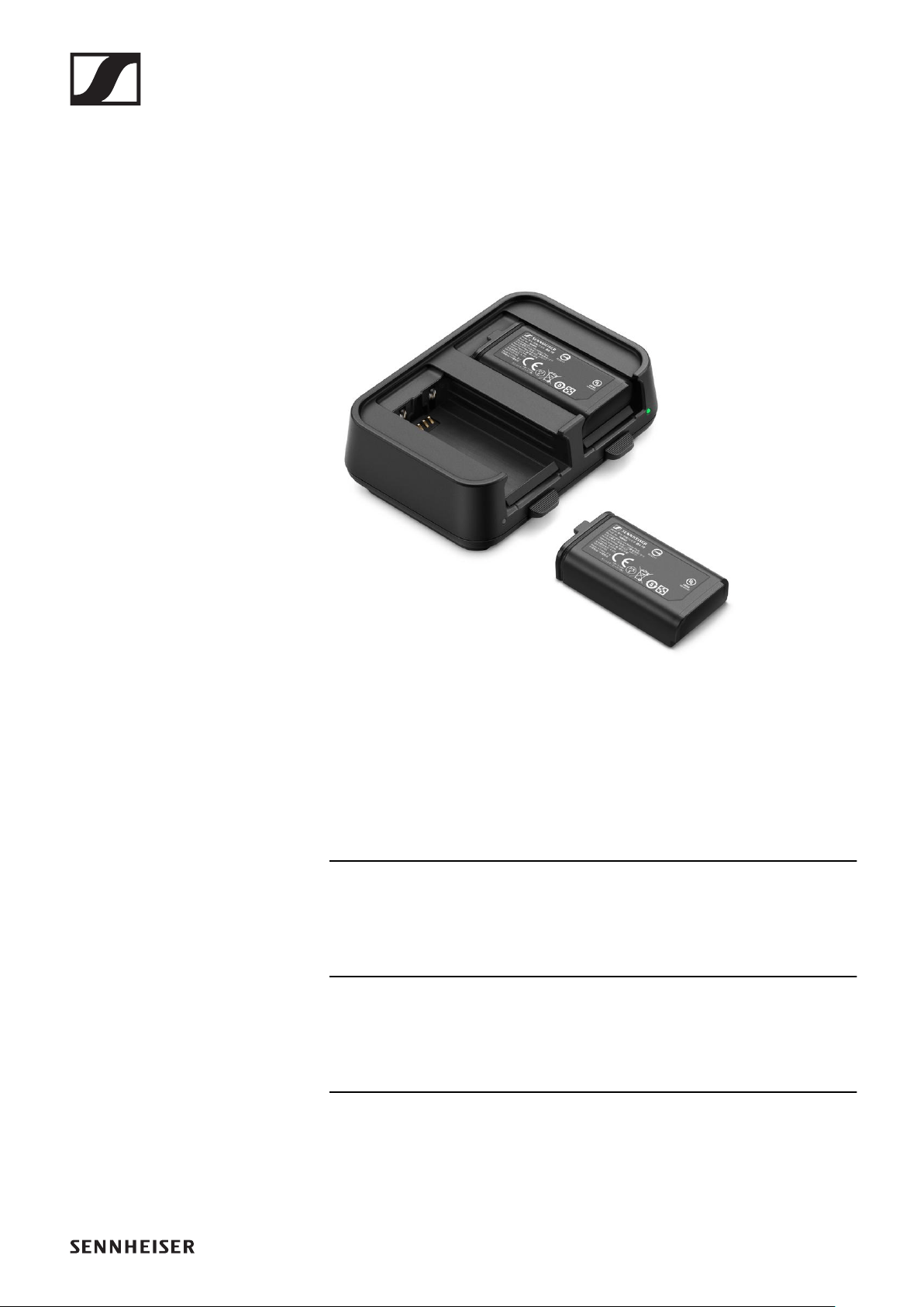
BA 70 rechargeable battery and L 70 USB
charger
►
BA 70 | Rechargeable battery | Art. no. 508860
L 70 USB | Charger | Art. no. 508861
EW-D CHARGING SET | L 70 USB charger with two BA 70 re-
chargeable batteries | Art. no. 508862
Startup and operation: „Charging the BA 70 rechargeable bat-
tery in the L 70 USB charger“
Specifications: „BA 70 rechargeable battery“ | „L 70 USB char-
ger“
Accessories
32
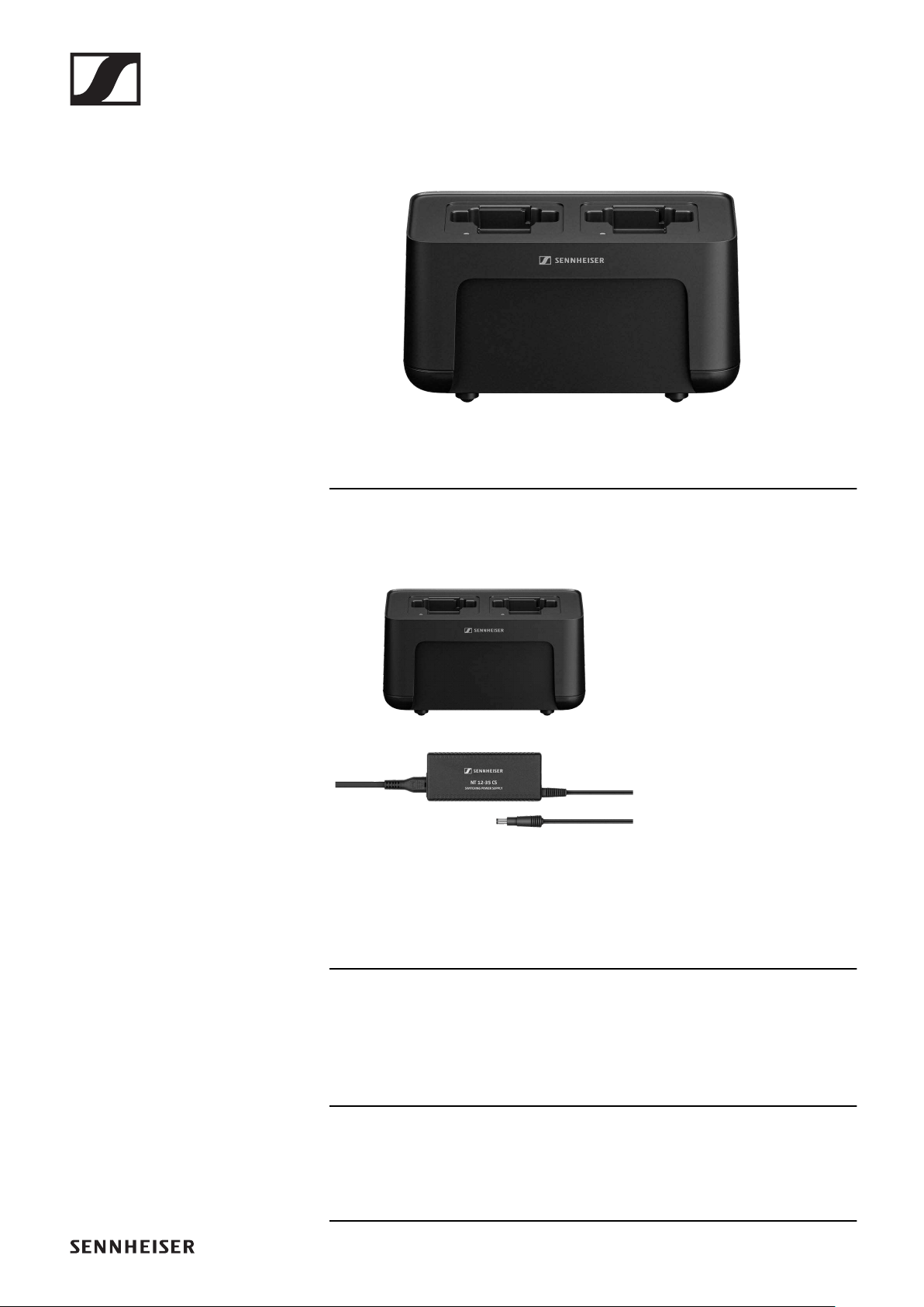
CHG 70N network-enabled charger
CHG 70N | Charger | Art. no. 509455
CHG 70N + PSU KIT | CHG 70N charger with NT 12-35 CS
power supply unit | Art. no. 509456
Startup and operation: „Charging the EW-DX SKM(-S) hand-
held transmitter, the EW-DX SK (3-PIN) bodypack transmitter
or the BA 70 rechargeable battery in the CHG 70N charger“
Specifications: „BA 70 rechargeable battery“ | „CHG 70N char-
ger“
Accessories
33
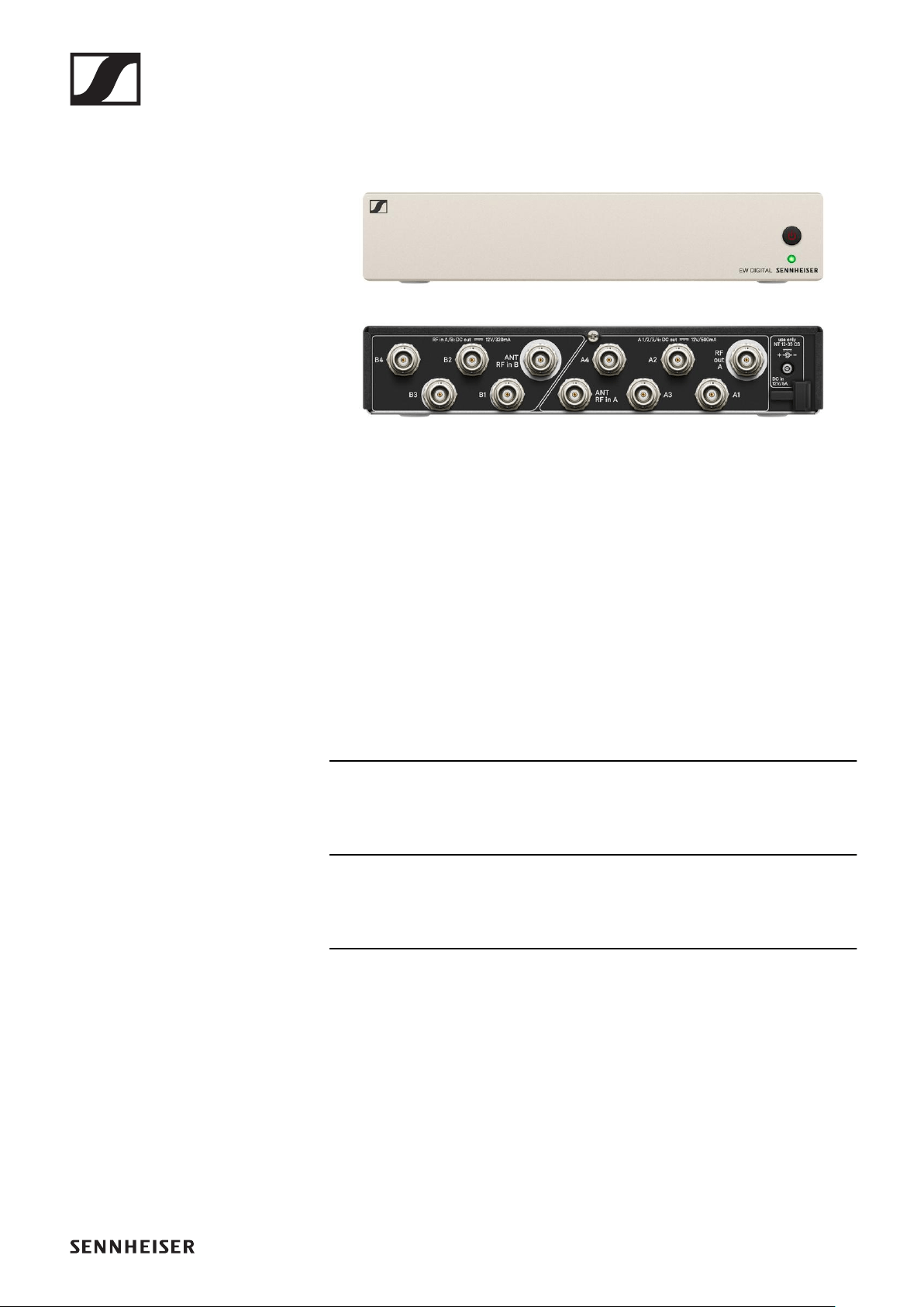
EW-D ASA antenna splitter
►
EW-D ASA active antenna splitter
Product versions:
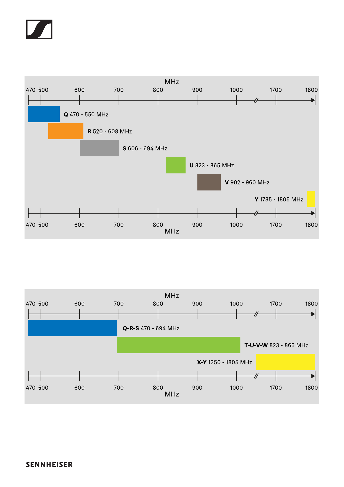
EW-D ASA (Q-R-S) | 470 – 694 MHz | Art. no. 508879
EW-D ASA CN/ANZ (Q-R-S) | 470 – 694 MHz | Art. no. 508998
EW-D ASA (T-U-V-W) | 694 – 1075 MHz | Art. no. 508880
EW-D ASA (X-Y) | 1350 – 1805 MHz | Art. no. 508881
Startup and operation: „EW-D ASA antenna splitter“
Specifications: „EW-D ASA antenna splitter“
Accessories
34
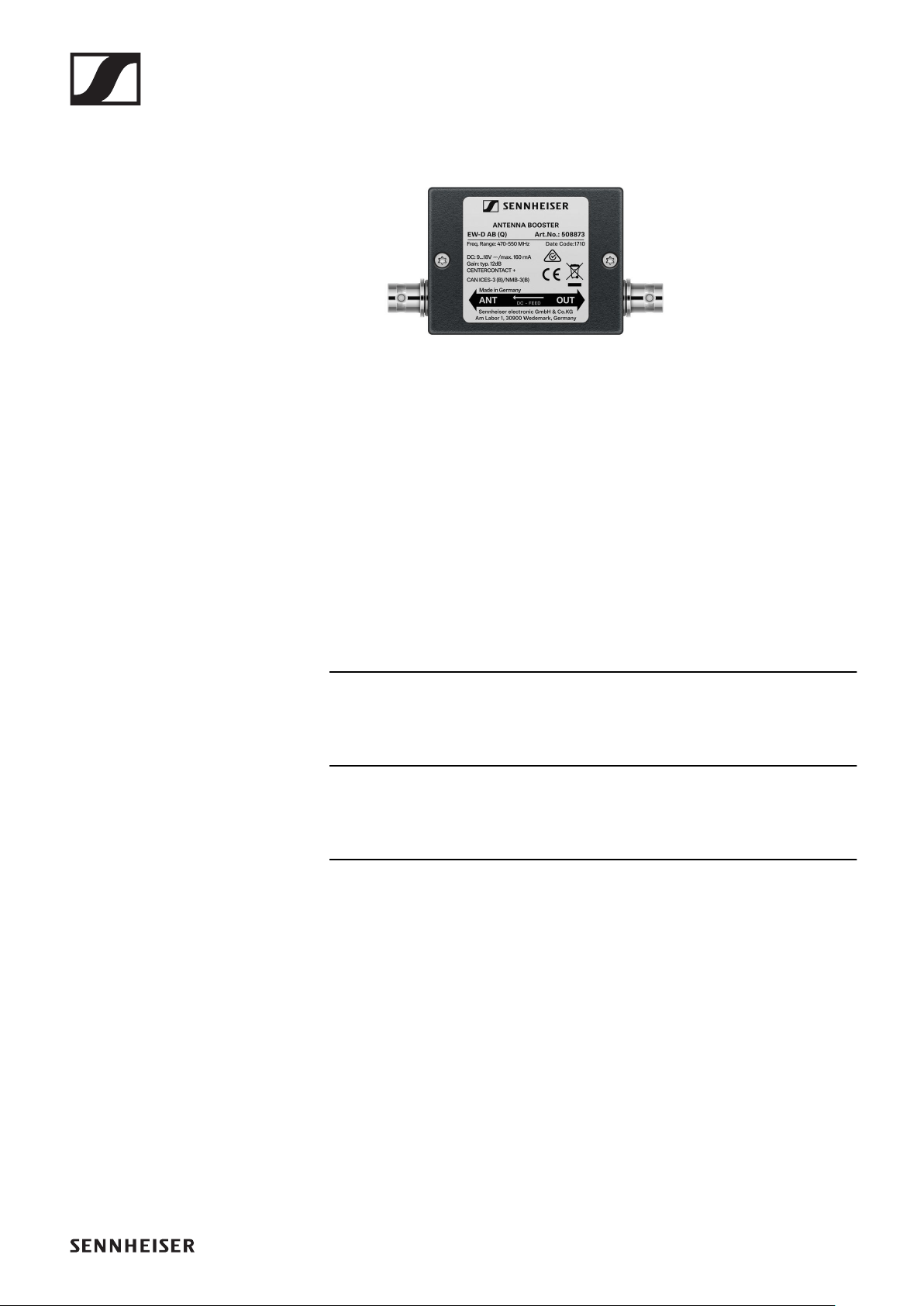
EW-D AB antenna booster
►
Product versions:
EW-D AB (Q) | 470 – 550 MHz | Art. no. 508873
EW-D AB (R) | 520 – 608 MHz | Art. no. 508874
EW-D AB (S) | 606 – 694 MHz | Art. no. 508875
EW-D AB (U) | 823 – 865 MHz | Art. no. 508876
EW-D AB (V) | 902 – 960 MHz | Art. no. 508877
EW-D AB (Y) | 1785 – 1805 MHz | Art. no. 508878
Use: „Information on antenna amplifiers and cable lengths“
Specifications: „EW-D AB antenna booster“
Accessories
35
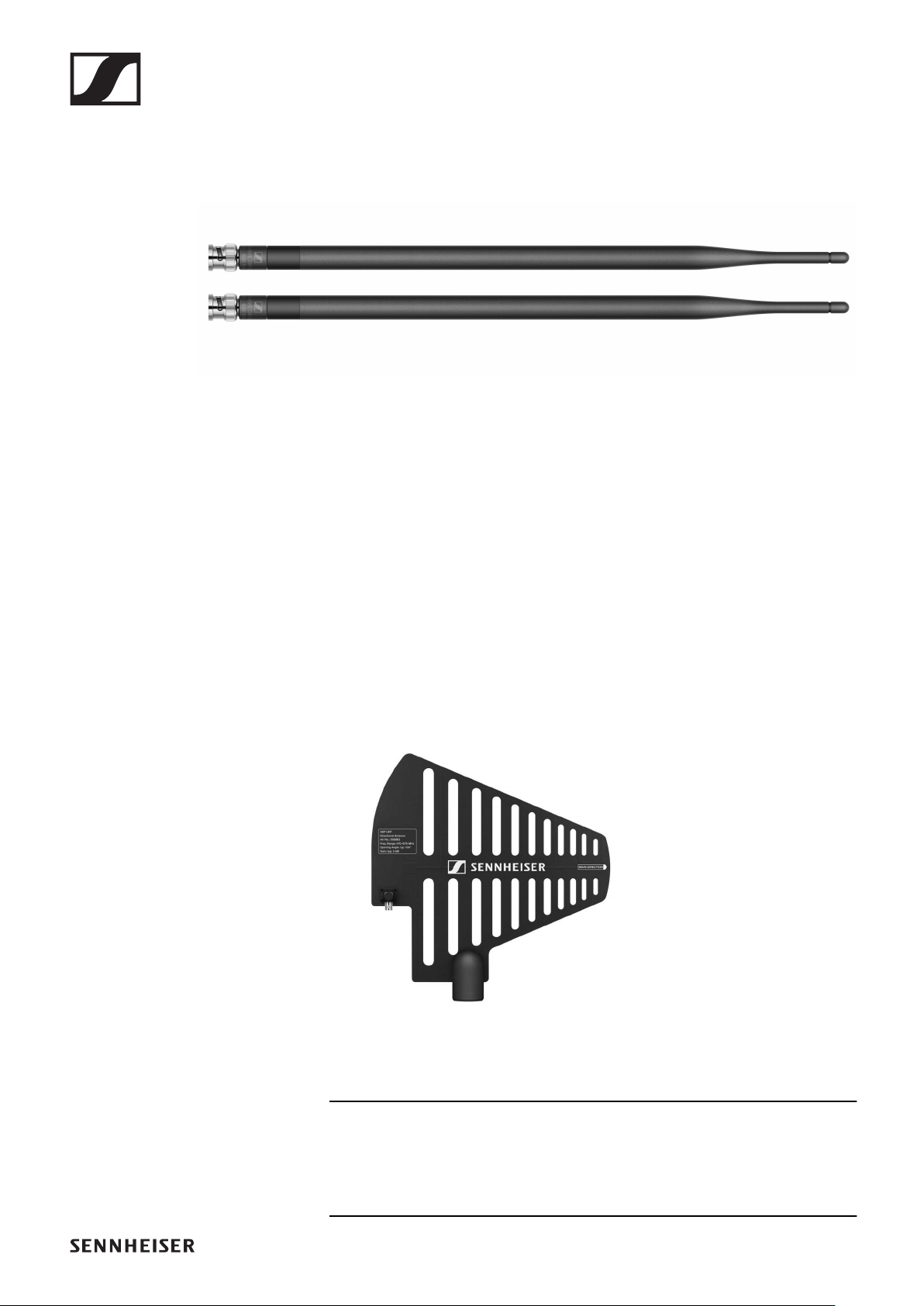
Antennas
Rod antennas
►
Product versions:
Half Wave Dipole (Q) | 470 – 550 MHz | Art. no. 508868
Half Wave Dipole (R) | 520 – 608 MHz | Art. no. 508869
Half Wave Dipole (S) | 606 – 694 MHz | Art. no. 508870
Half Wave Dipole (U) | 823 – 865 MHz | Art. no. 508871
Half Wave Dipole (V) | 902 – 960 MHz | Art. no. 508966
Half Wave Dipole (Y) | 1785 – 1805 MHz | Art. no. 508872
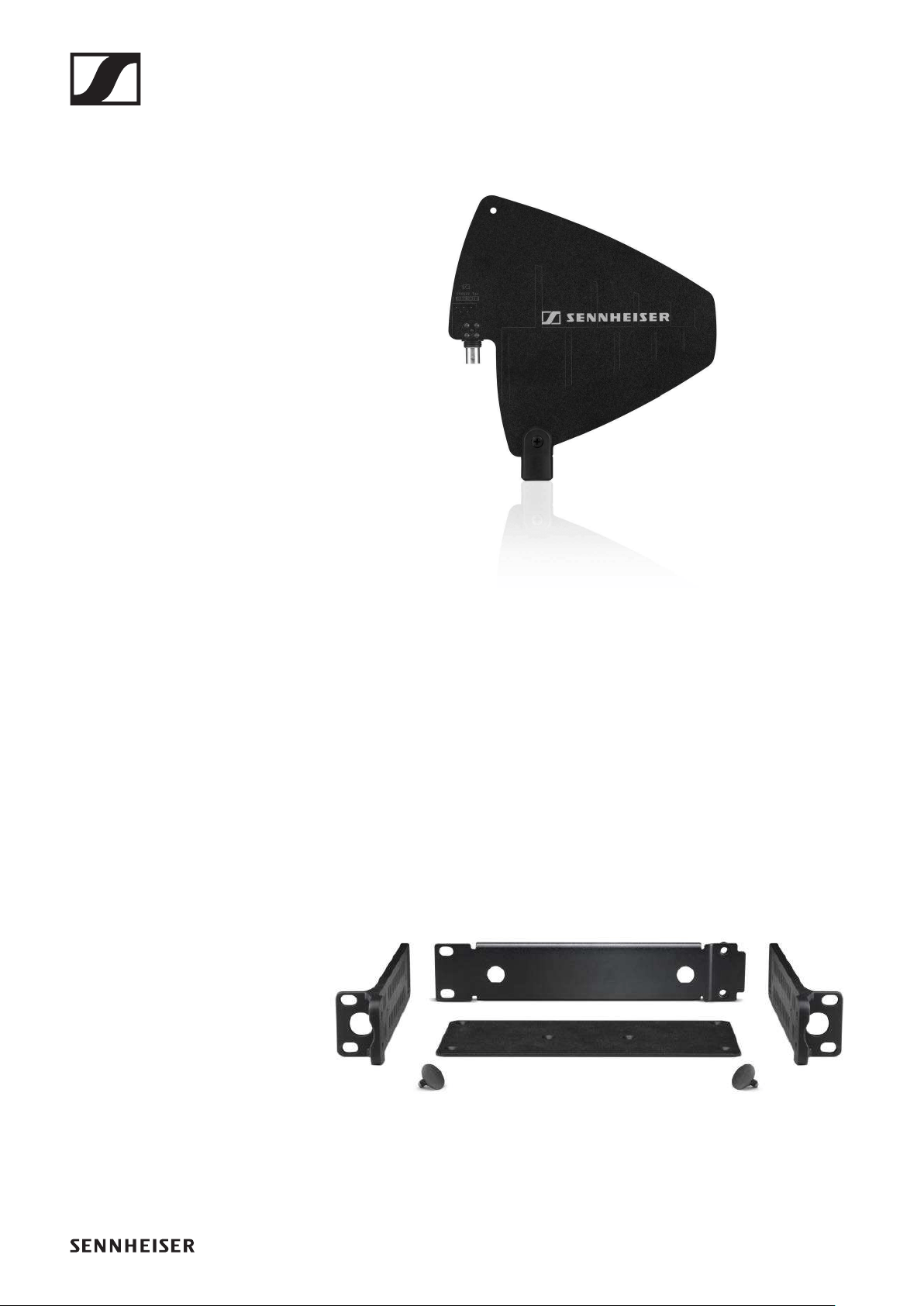
ADP UHF passive directional antenna (470 – 1075
MHz)
►
ADP UHF | 470 – 1075 MHz | Art. no. 508863
Specifications: „ADP UHF passive directional antenna (470 –
1075 MHz)“
Accessories
36
AD 1800 passive directional antenna
►
AD 1800 | 1400 – 2400 MHz | Art. no. 504916
Accessories for rack mounting
GA 3 rack mount kit
19" rack adapter for mounting the EW-D EM, EW-DX EM 2 or
EW-D ASA in a 19" rack.
Art. no. 503167
►
Accessories
37
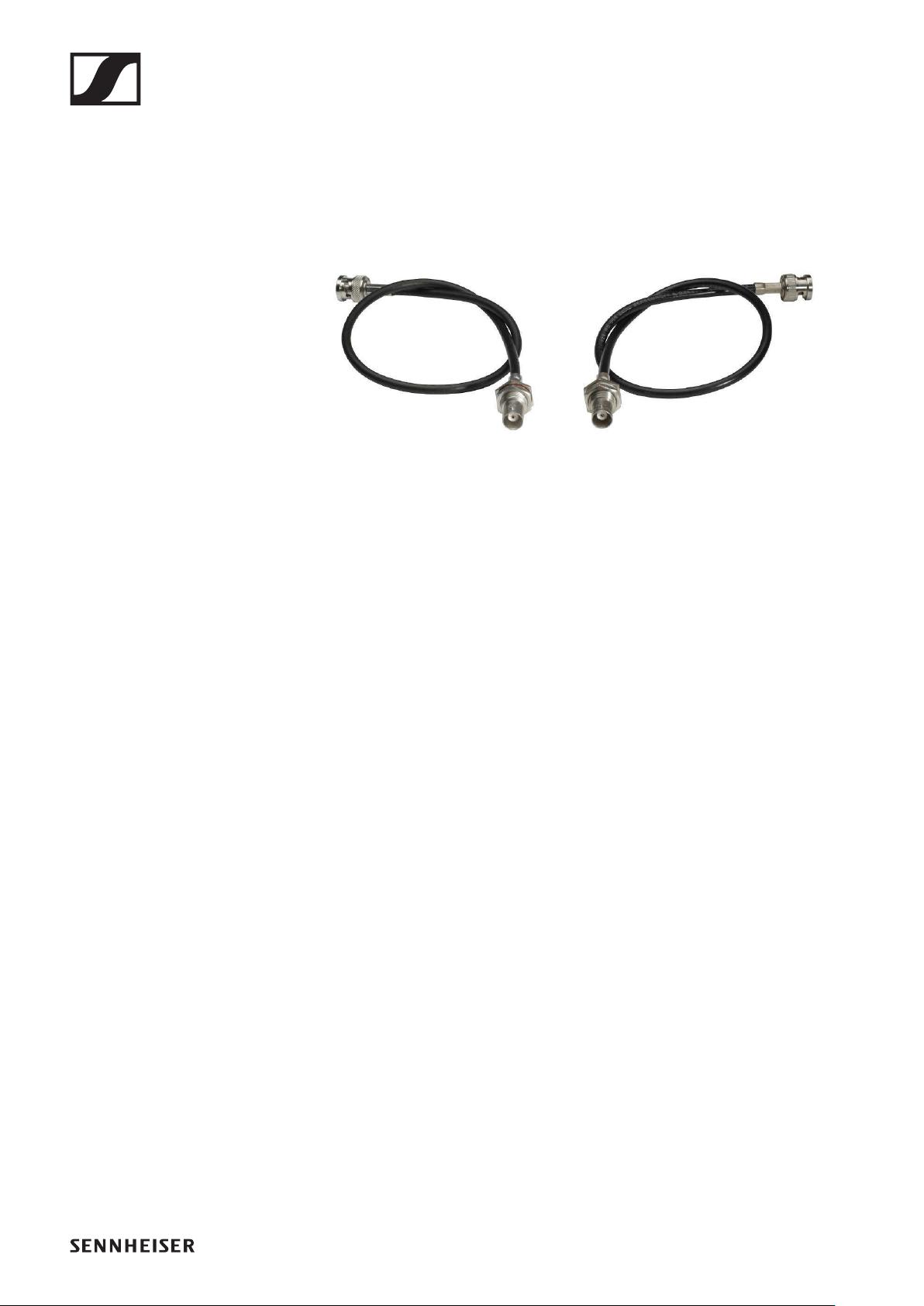
AM 2 antenna front mount kit
Antenna front mount kit for installing antenna connections on
the front of the rack when using the EW-D EM, EW-DX EM 2 or
EW-D ASA together with the GA 3 rack mount kit.
Art. no. 009912
►
Accessories
39
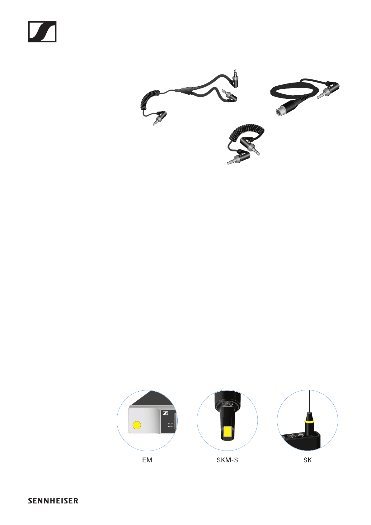
Cables for EW-DP EK
3.5 mm jack cable, 3.5 mm Y-cable and 3.5 mm XLR cable for
connecting one or more EW-DP EK units to a camera.
▷Startup and operation: „EW-DP EK portable receiver“
CL 35 | 3.5 mm jack cable | Art no. 586365
CL 35-Y | 3.5 mm Y-cable | Art. no. 700061
CL 35 XLR | 3.5 mm XLR cable | Art. no. 700062
Color Coding Sets
EW-D COLOR CODING SET | For EM, SKM-S, SK |
Art. no. 508989
EW-D SK COLOR CODING | For SK | Art. no. 508990
EW-D SKM COLOR CODING | For SKM-S | Art. no. 508991
EW-D EM COLOR CODING | For EM | Art. no. 508992
▷„Using EW-D Color Coding Sets to label transmission
paths“
Frequency ranges
40
Frequency ranges
Frequency tables with the factory presets for all available fre-
quency ranges can be found in the download area of the Senn-
heiser website at:
www.sennheiser.com/download
▷Enter EW-D or EW-DP in the search bar to show the fre-
quency tables.
EW-D | EW-DP
The products EW-D EM, EW-D SKM-S, EW-D SK and
EW-DP EK are available in the following frequency ranges:
►
Frequency ranges
41
EW-DX
The EW-DX EM 2, EW-DX SKM, EW-DX SKM-S, EW-DX SK
and EW-D SK 3-PIN products are available in the following fre-
quency ranges:
►
Frequency ranges
42
Accessories
The EW-D AB antenna booster and the Half Wave Dipole rod
antennas are available in the following frequency ranges:
►
The EW-D ASA antenna splitter is available in the following
frequency ranges:
►

Starting up and operating devices of the Evolution Wireless Digital series
43
INSTRUCTION MANUAL
Starting up and operating devices of the
Evolution Wireless Digital series
Products of the EW-D series
▷"EW-D EM rack receiver"
▷"EW-D SKM-S handheld transmitter"
▷"EW-D SK bodypack transmitter"
Products of the EW-DX series
▷"EW-DX EM 2 rack receiver"
▷"EW-DX SKM | EW-DX SKM-S handheld transmitter"
▷"EW-DX SK | EW-DX SK 3-PIN bodypack transmitter"
Products of the EW-DP series
▷"EW-DP EK portable receiver"
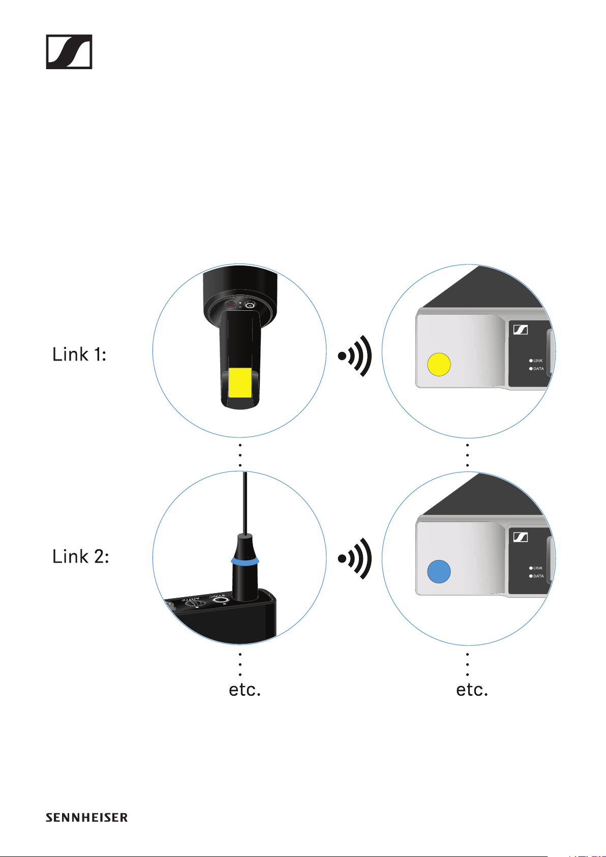
Establishing a radio link and synchronizing devices
/ Compatibility between EW-D, EW-DX and EW-DP
▷"Establishing a radio link | Synchronizing the receiver and
transmitter"
Accessories
▷"Charging the BA 70 rechargeable battery in the L 70 USB
charger"
▷"Charging the EW-DX SKM(-S) handheld transmitter, the
EW-DX SK (3-PIN) bodypack transmitter or the BA 70 re-
chargeable battery in the CHG 70N charger"
▷"EW-D ASA antenna splitter"
Cleaning and maintenance
▷"Cleaning and maintenance"
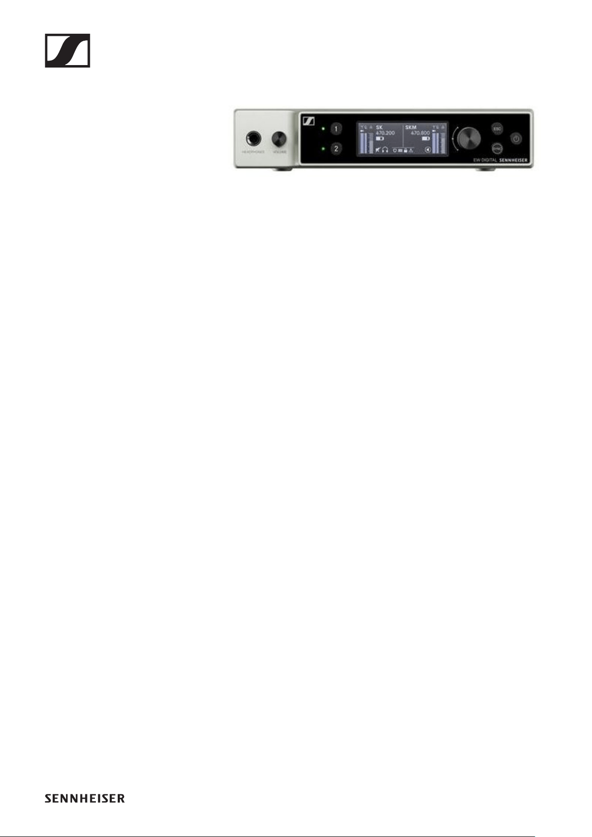
EW-D EM rack receiver
44
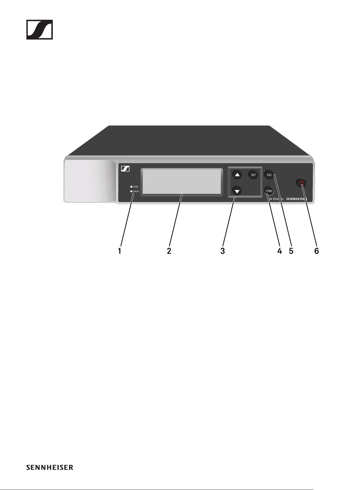
EW-D EM rack receiver
Product overview
Front
1LINK and DATA LEDs to indicate connection status and
Bluetooth status
•See "Meaning of the LEDs"
2Display for status information and operating menu
•See "Displays on the receiver’s display panel"
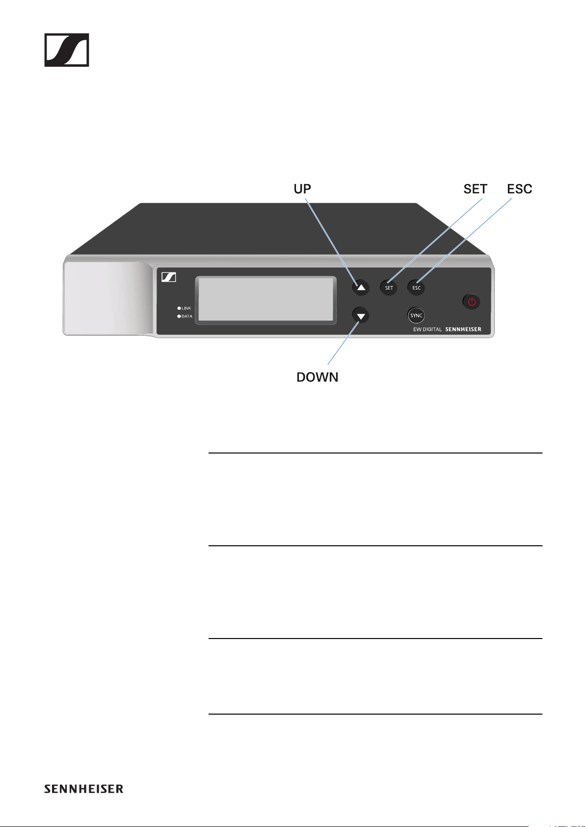
3UP/DOWN/SET menu buttons for navigating the operating
menu
•See "Making settings in the menu"
4SYNC button for synchronizing the transmitter and receiver
•See "Establishing a radio link | Synchronizing the receiver
and transmitter"
5ESC button for canceling an action in the menu
•See "Making settings in the menu"
6ON/OFF button for switching the device on and off
•See "Switching the receiver on and off"
EW-D EM rack receiver
45
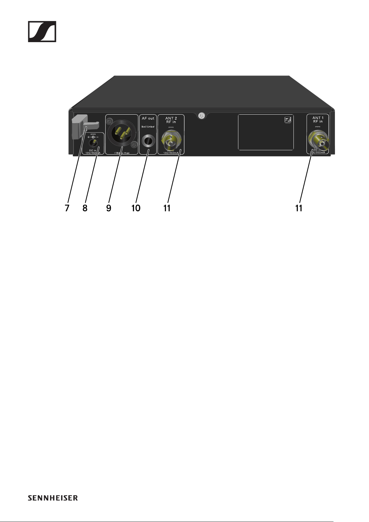
Back
7
Strain relief for the connection cable of the power supply
unit
•See "Connecting/disconnecting the receiver to/from the
power supply system"
8DC in connection socket for the power supply unit
•See "Connecting/disconnecting the receiver to/from the
power supply system"
9XLR-3 socket AF out Bal for audio output
•See "Outputting audio signals"
106.3 mm jack socket AF out Unbal for audio output
•See "Outputting audio signals"
11BNC sockets ANT 1 RF in and ANT 2 RF in for antenna inputs
•See "Connecting antennas"
EW-D EM rack receiver
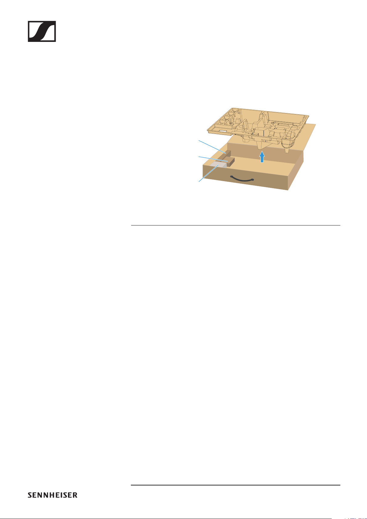
46
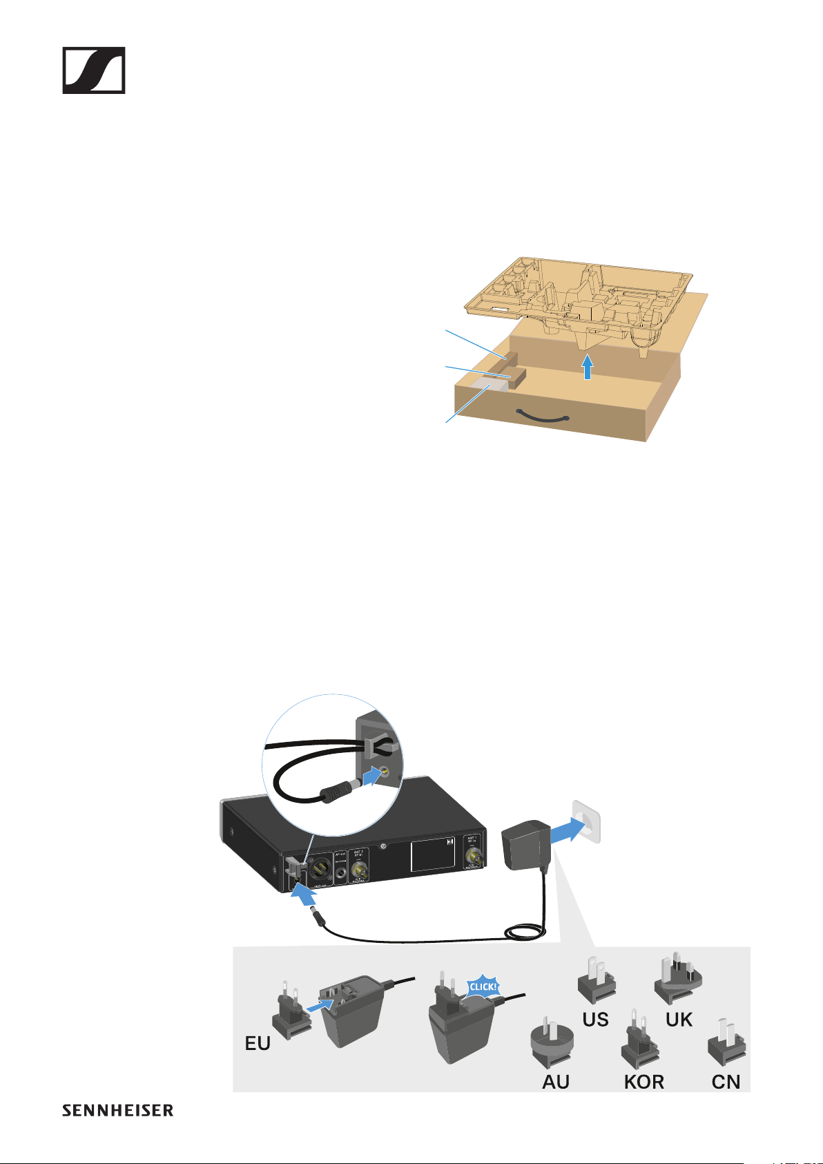
Connecting/disconnecting the receiver to/
from the power supply system
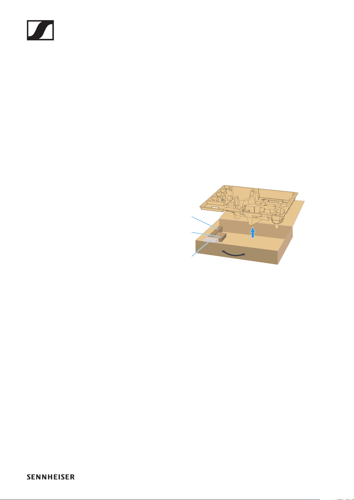
Only use the supplied power supply unit. It is designed for your
receiver and ensures safe operation.
You will f i nd t he po wer suppl y uni t and t he countr y adapt-
ers in the packaging under the tray:
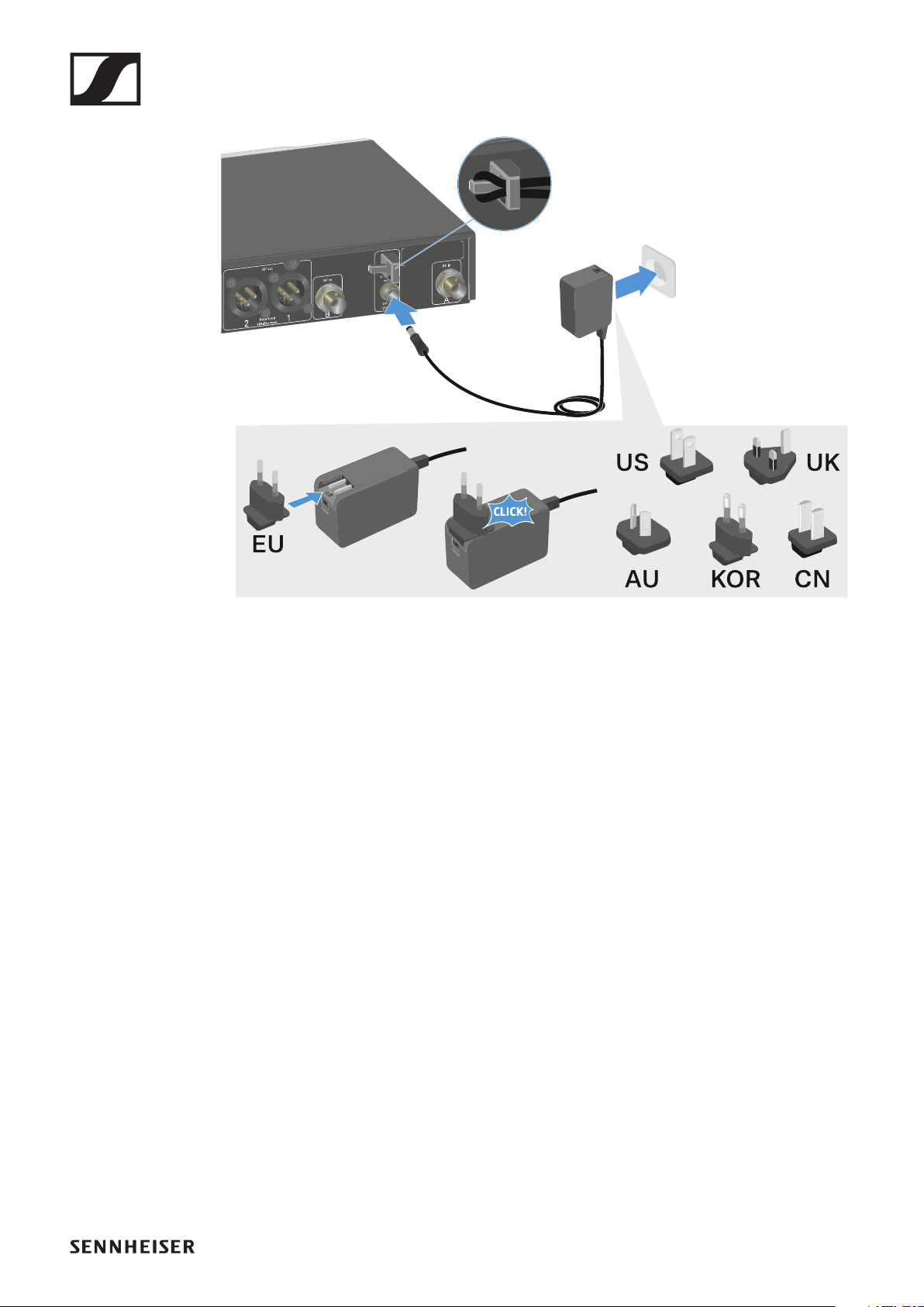
To connect the receiver to the power supply system:
▷Insert the plug of the power supply unit into the DC in sock-
et on the receiver.
▷Pass the cable of the power supply unit through the strain
relief.
▷Slide the supplied country adapter onto the power supply
unit.
▷Plug the power supply unit into the wall socket.
Rack mount angles
Power supply unit
Power supply adapters
EW-D EM rack receiver
47
To completely disconnect the receiver from the power supply
system:
▷Unplug the power supply unit from the wall socket.
▷Unplug the power supply unit from the DC in socket on the
receiver.
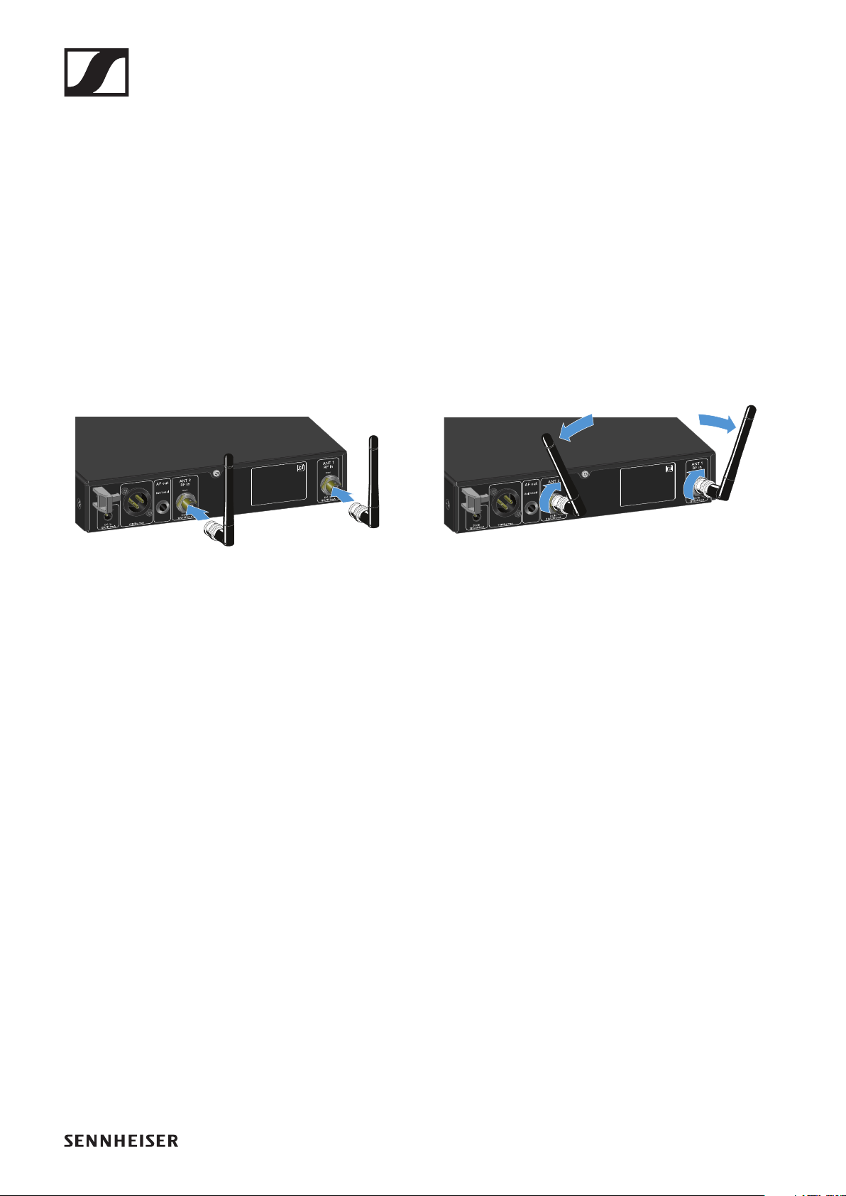
Connecting antennas
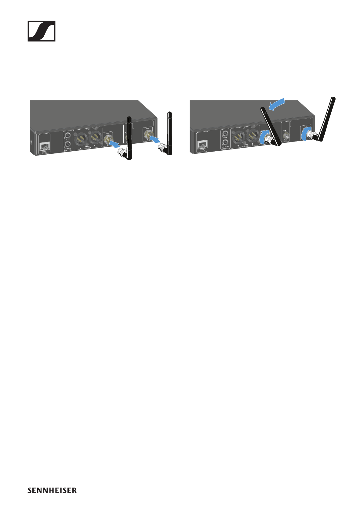
Connecting rod antennas
To connect the supplied rod antennas:
►
▷Connect the antennas to the two antenna inputs on the re-
ceiver as shown in the figure.
▷Slightly angle the antennas to the left and right as shown in
the figure.
If you are using more than one receiver, we recommend using
remote antennas and possibly the EW-D ASA antenna splitter
("EW-D ASA antenna splitter").
EW-D EM rack receiver
48
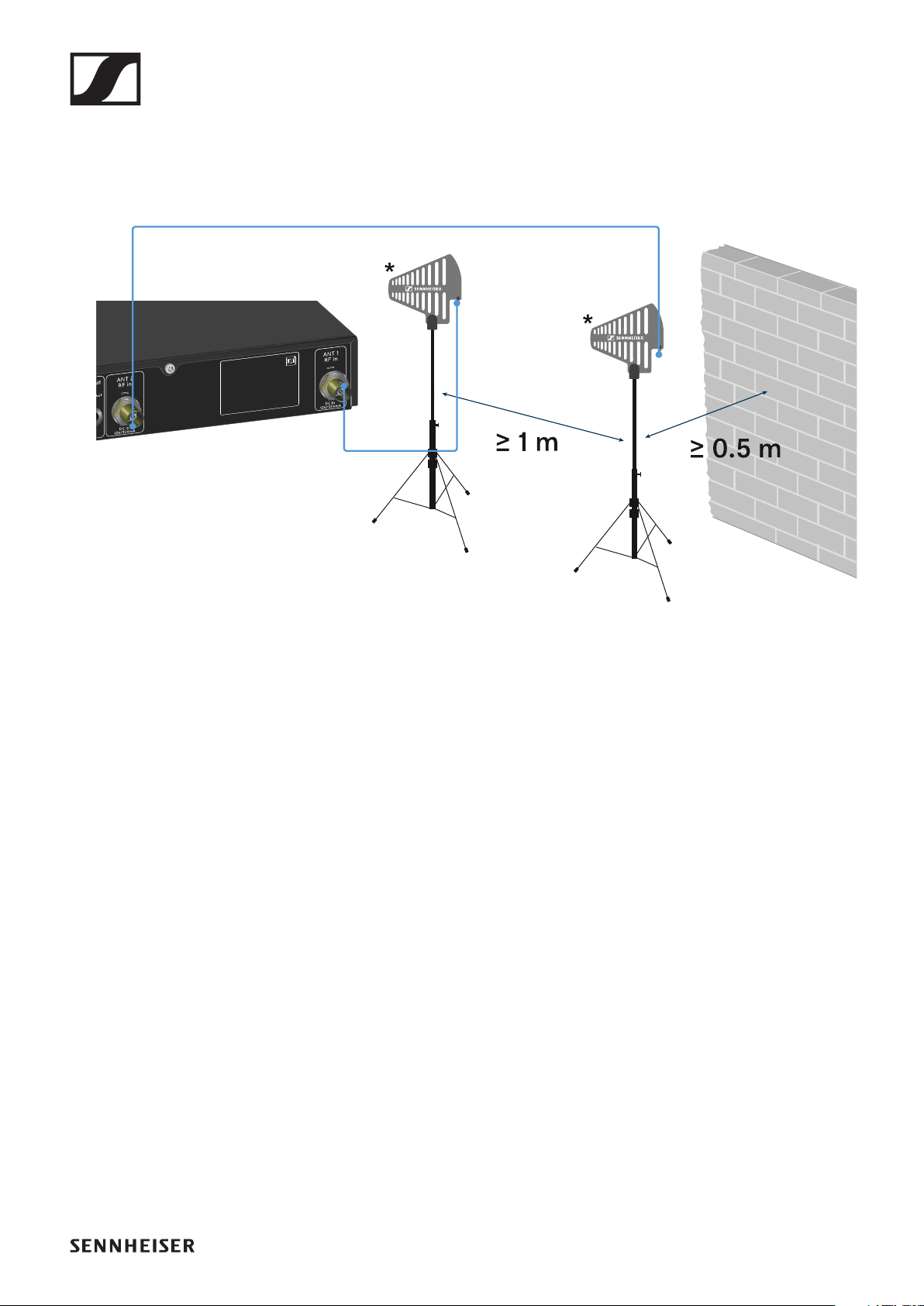
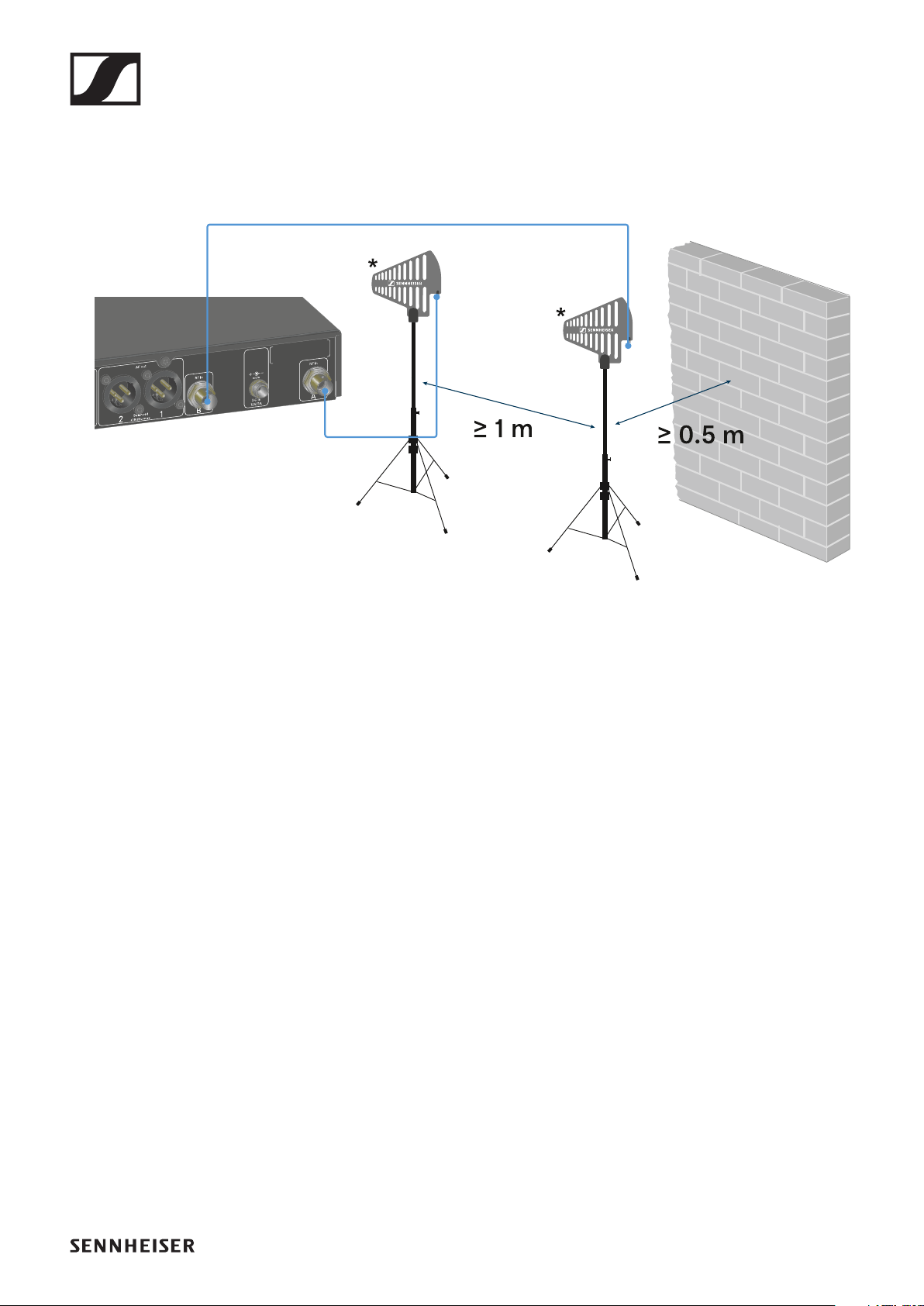
Connecting remote antennas
To connect remote antennas:
►
▷Connect the antennas to the two antenna inputs on the re-
ceiver as shown in the figure.
▷Observe the specified minimum spacing.
*Recommended antennas:
•ADP UHF | 470 – 1075 MHz
•AD 1800 | 1400 – 2400 MHz
If you are using more than one receiver, we recommend using
remote antennas and possibly the EW-D ASA antenna splitter
("EW-D ASA antenna splitter").
EW-D EM rack receiver
49
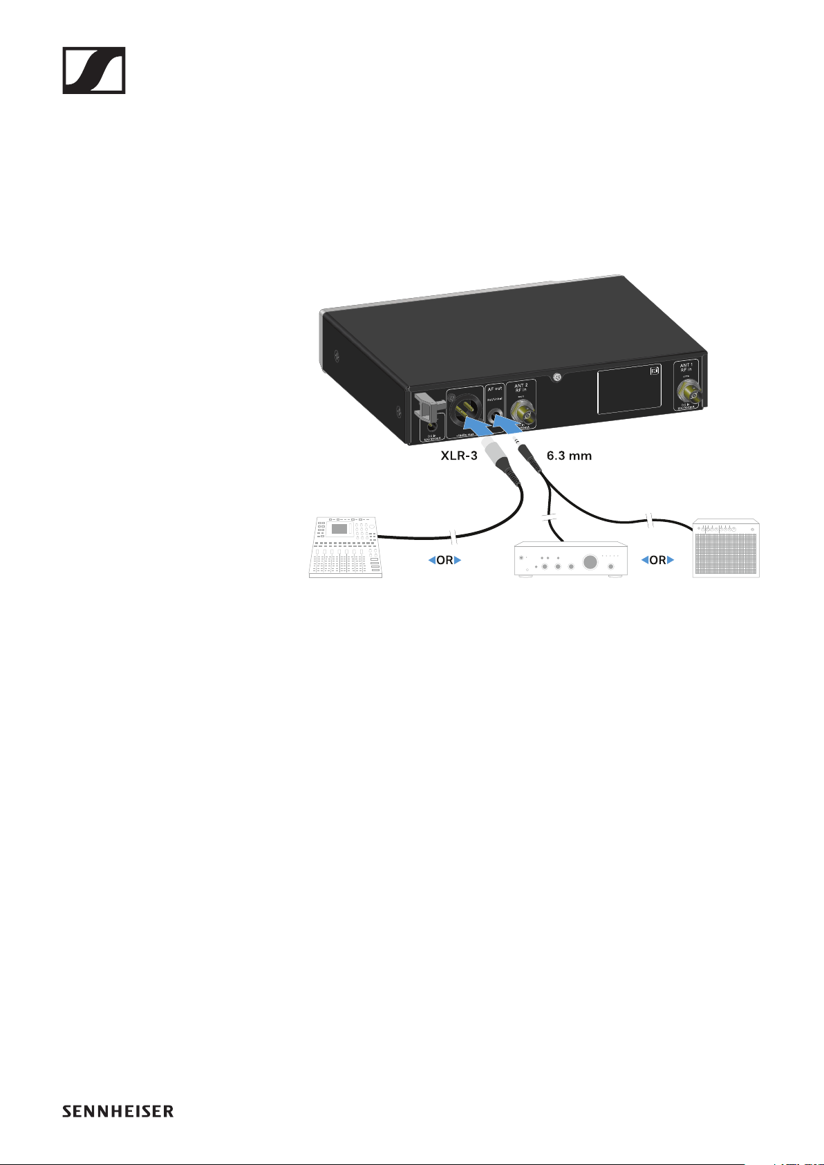
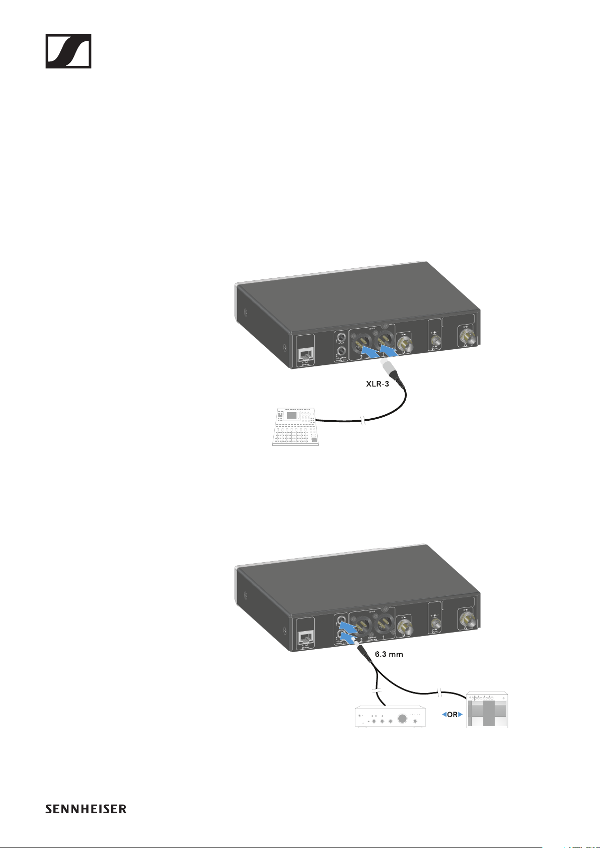
Outputting audio signals
The EW-D EM has a balanced XLR-3M output socket and an
unbalanced 6.3 mm jack output socket.
▷Always use only one of the two output sockets.
To connect an XLR cable:
▷Plug the XLR cable into the AF out Bal socket on the EW-D
EM.
To connect a jack cable:
▷Plug the jack cable into the AF out Unbal socket on the EW-
D EM.

EW-D EM rack receiver
50
Installing receivers in a rack
Observe the following instructions when mounting the receiv-
er in a rack.
The mounting brackets for installing the receiver in the rack
can be found in the packaging under the tray:
CAUTION!
Rack mounting poses risks
When installing the device in a closed 19" rack or multi-rack
assembly, please consider that, during operation, the ambient
temperature, the mechanical load and the electrical potentials
will be different from those of devices which are not mounted
into a rack.
▷Make sure that the ambient temperature within the rack
does not exceed the permissible temperature limit stated
in the specifications. See "SPECIFICATIONS".
▷Ensure sufficient ventilation; if necessary, provide addi-
tional ventilation.
▷Make sure that the mechanical load of the rack is even.
▷When connecting to the power supply system, observe the
information indicated on the type plate. Avoid overloading
the circuits. If necessary, provide overcurrent protection.
▷When mounting in a rack, please note that intrinsically
harmless leakage currents of the individual power supply
units may accumulate, thereby exceeding the permissible
limit value. As a remedy, ground the rack via an additional
ground connection.
Rack mount angles
Power supply unit
Power supply adapters
EW-D EM rack receiver
51
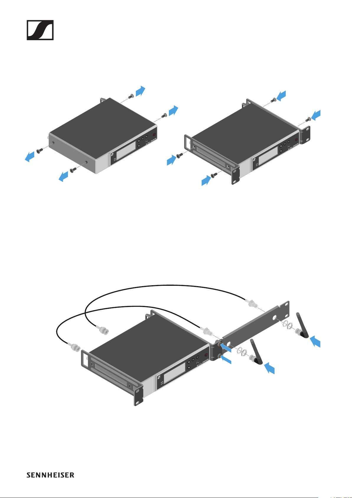
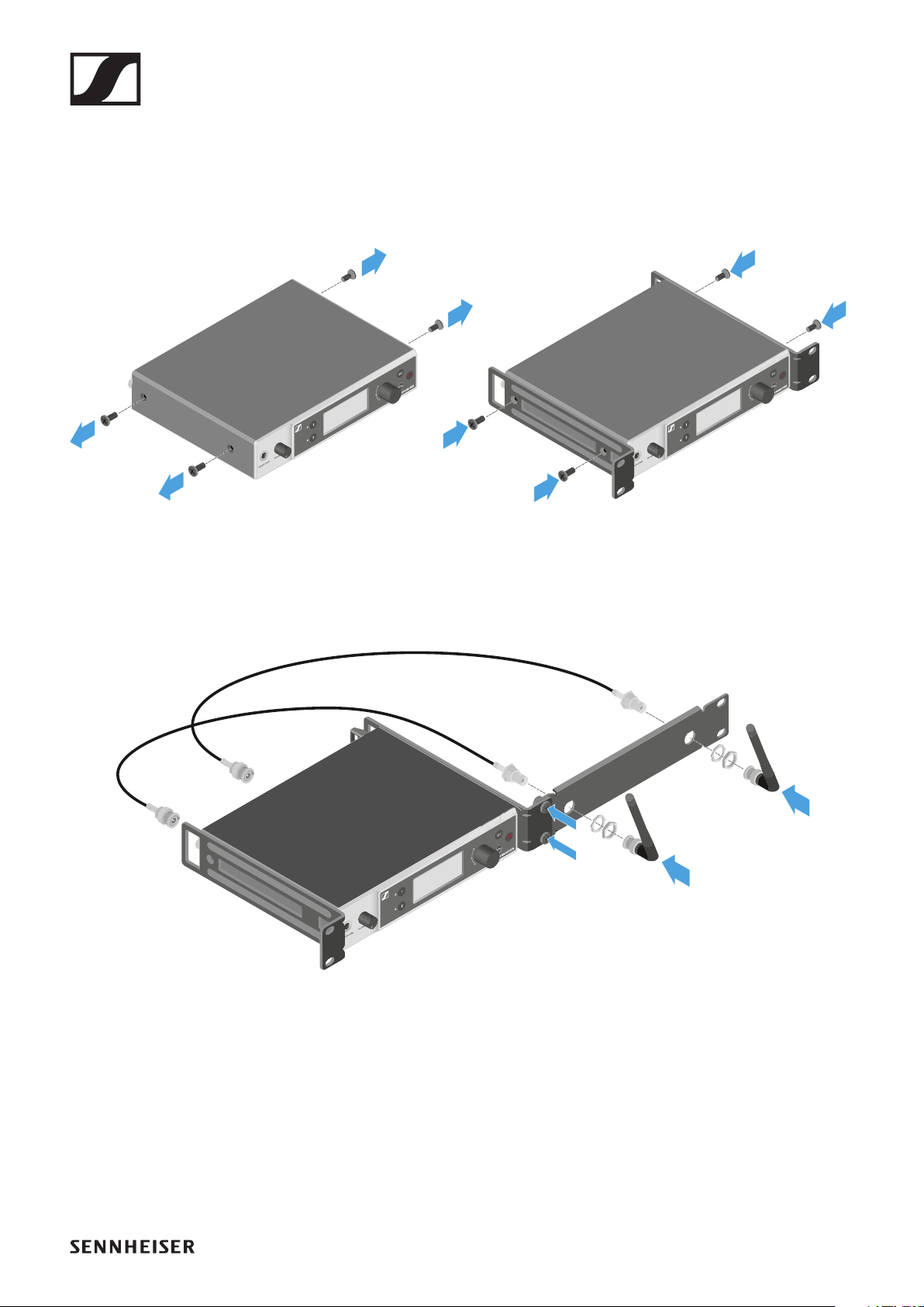
Mounting a single receiver in a rack
▷Connect the mounting brackets to the sides of the receiver
as shown.
▷Attach the front panel as shown.
▷If desired, attach the antennas to the front panel as shown.
This requires the optional AM 2 antenna front mount kit
(see "Accessories for rack mounting").
EW-D EM rack receiver
52
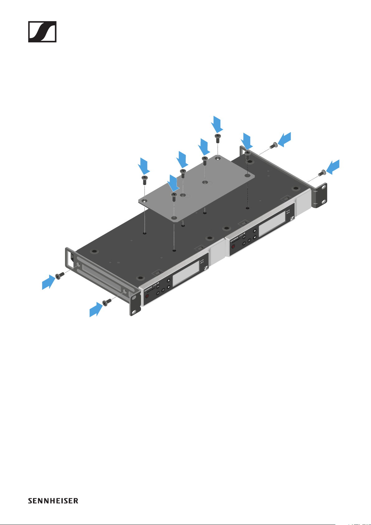
Mounting two receivers side by side in a rack
▷Place both receivers upside down and side by side on an
even surface.
▷Tighten the jointing plate as shown.
▷Attach the mounting brackets as shown.
EW-D EM rack receiver
53
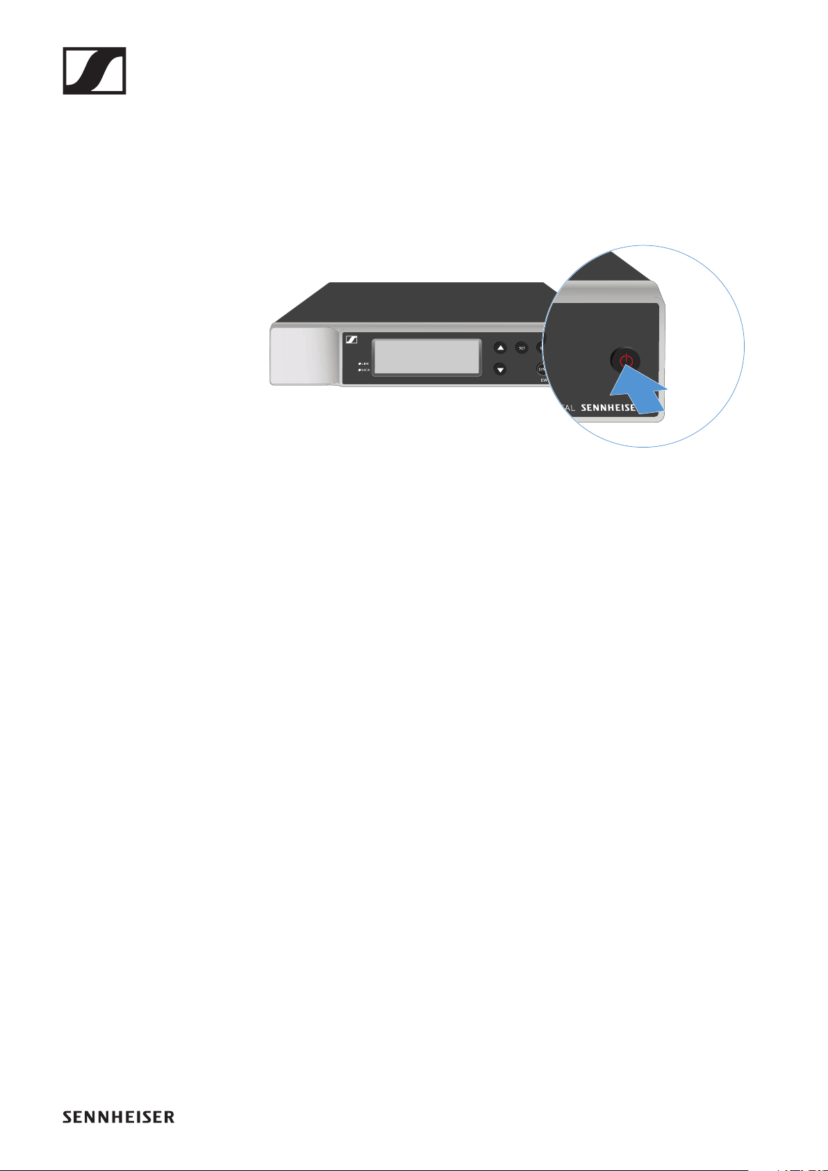
Switching the receiver on and off
To switch the receiver
on:
▷Short-press the ON/OFF button.
The receiver switches on.
To switch the receiver to
standby mode:
▷If necessary, deactivate the lock-off function (see "Lock-off
function").
▷Hold down the ON/OFF button until the display switches
off.
To
switch the receiver off completely:
▷Disconnect the receiver from the power supply system by
unplugging the power supply unit from the wall socket.
EW-D EM rack receiver
54
Lock-off function
To activate the key lock:
▷Press the UP and DOWN buttons simultaneously.
Key lock is activated and the lock icon is shown on the dis-
play.
►
To deactivate the key lock:
▷Simultaneously press the UP and DOWN buttons again.
Key lock is deactivated and the lock icon disappears from
the display.
►
EW-D EM rack receiver
55
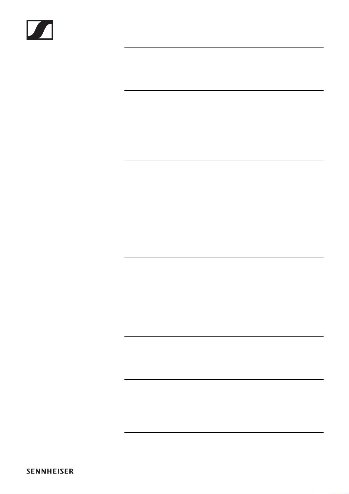
Meaning of the LEDs
The LINK and DATA LEDs on the front of the receiver can in-
dicate the following information.
LINK LED
The LINK LED provides information about the status of the ra-
dio link between the transmitter and receiver, as well as status
information for the paired transmitter.
The LED is green:
▷The link between the transmitter and receiver is estab-
lished.
▷The audio signal is active.
The LED is yellow:
▷The link between the transmitter and receiver is estab-
lished.
▷The audio signal is muted.
or
▷No microphone module is mounted on the SKM-S handheld
transmitter.
The LED is flashing yellow:
▷The link between the transmitter and receiver is estab-
lished.
▷The audio signal is overdriven (clipping).
EW-D EM rack receiver
56
The LED is continuously red:
▷No link between the transmitter and receiver.
The LED is flashing red:
▷The link between the transmitter and receiver is estab-
lished.
▷The battery/rechargeable battery in the paired transmitter
is low.
DATA LED
The DATA LED provides information on the receiver’s Blue-
tooth Low Energy link to the EW-D Smart Assist app and on
the synchronization of transmitters and receivers.
The LED is flashing blue:
▷The Bluetooth Low Energy link is being established be-
tween the receiver and a smartphone or tablet with the
EW-D Smart Assist app.
or
▷The receiver is being synchronized with a transmitter.
The LED is continuously blue:
▷The firmware is being updated.
The LED is off:
▷Normal operation
▷There is currently no active data link.
EW-D EM rack receiver
57
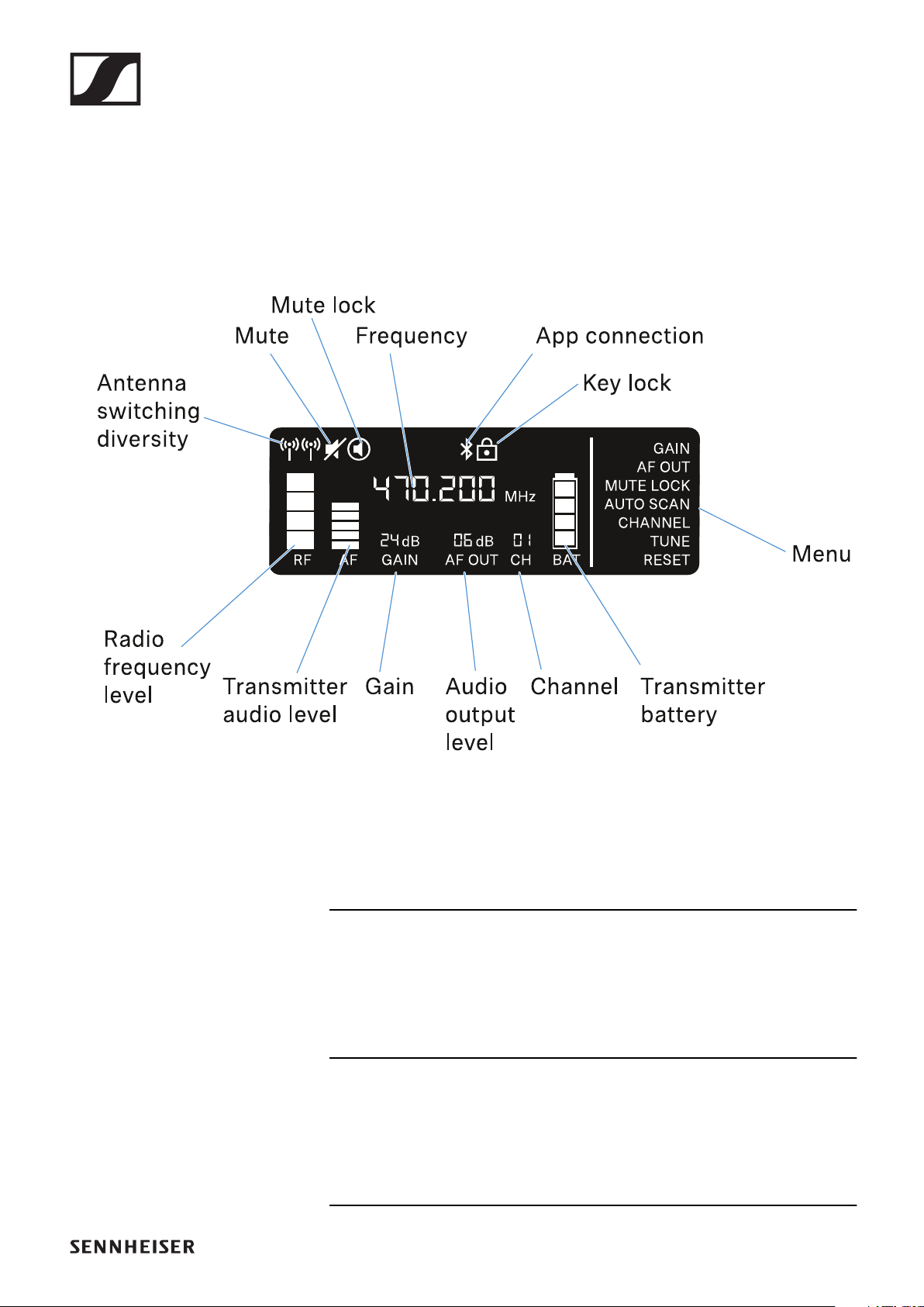
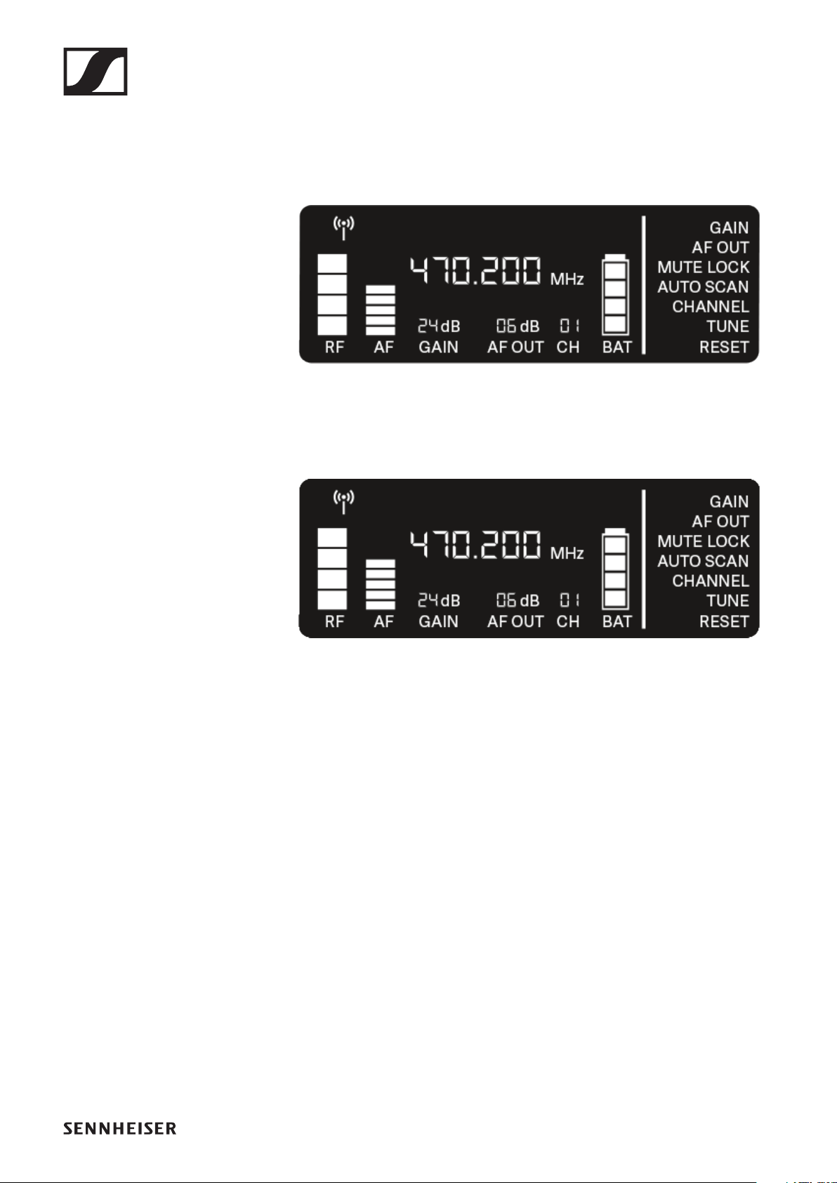
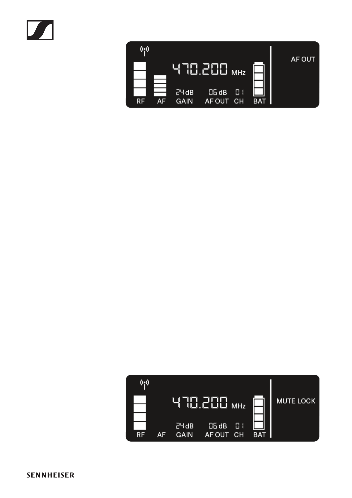
Displays on the receiver’s display panel
Status information such as frequency, reception quality, bat-
tery status and audio level is shown on the display.
The display also shows the operating menu, which you can use
to configure all of the settings (see "Making settings in the
menu").
Further information
Antenna switching diversity / radio level:
"Establishing a radio link | Synchronizing the receiver and
transmitter"
Mute / mute lock:
"MUTE LOCK menu item" | "Muting the handheld transmitter"
| "Muting the bodypack transmitter"
EW-D EM rack receiver
58
Frequency:
"AUTO SCAN menu item" | "CHANNEL menu item" | "TUNE
menu item"
Connecting to the app:
"EW-D Smart Assist app"
Lock-off function:
"Lock-off function"
Menu:
"Making settings in the menu"
Transmitter battery:
SKM-S -> "Inserting and removing the batteries/rechargeable
batteries" | SK -> "Inserting and removing the batteries/re-
chargeable batteries"
Channel:
"CHANNEL menu item"
Audio output level:
"AF OUT menu item"
Gain:
"GAIN menu item"
Transmitter audio level:
"GAIN menu item"
EW-D EM rack receiver
59
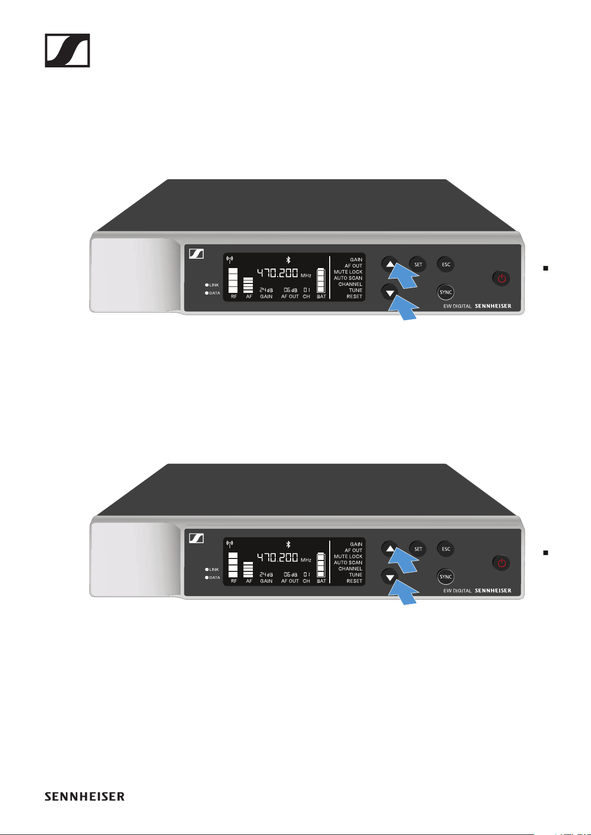
Making settings in the menu
Buttons for navigating the menu
Use the following buttons to navigate through the receiver’s
operating menu.
►
Press the SET button
•Open the menu
•Save settings in a menu item
Press the UP or DOWN button
•Changes to the previous or next menu item
•Changes the setting of a menu item
Press the ESC button
•Cancel input
EW-D EM rack receiver
60
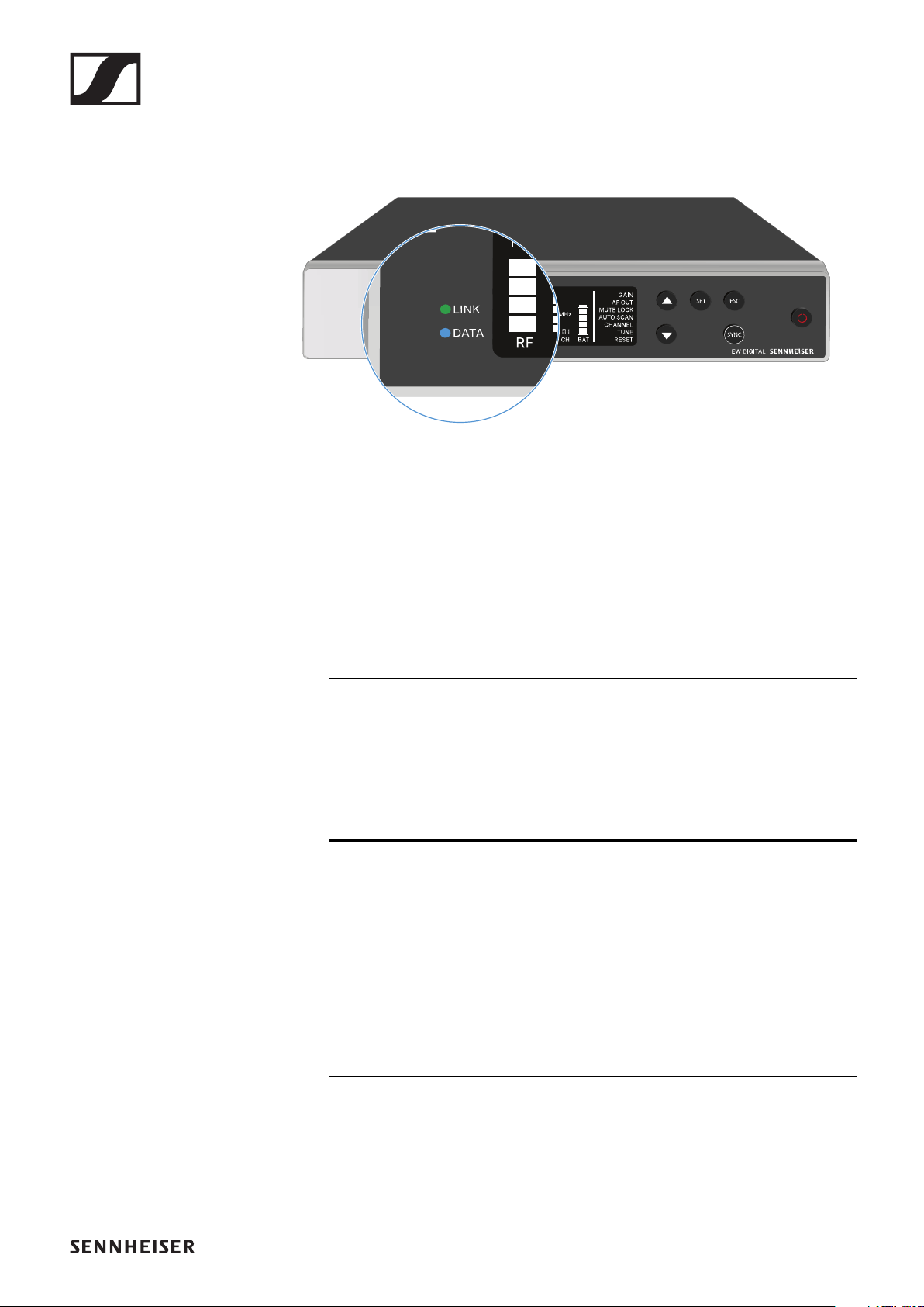
Opening the menu and navigating the menu items
To open the menu:
▷Press the SET button.
The first menu item GAIN flashes.
►
To navigate the menu items:
▷Press the UP and DOWN buttons.
The currently active menu item flashes.
►
To open a menu item:
▷Navigate to the desired menu item until it flashes.
▷Press the SET button to open the selected menu item.
EW-D EM rack receiver
61
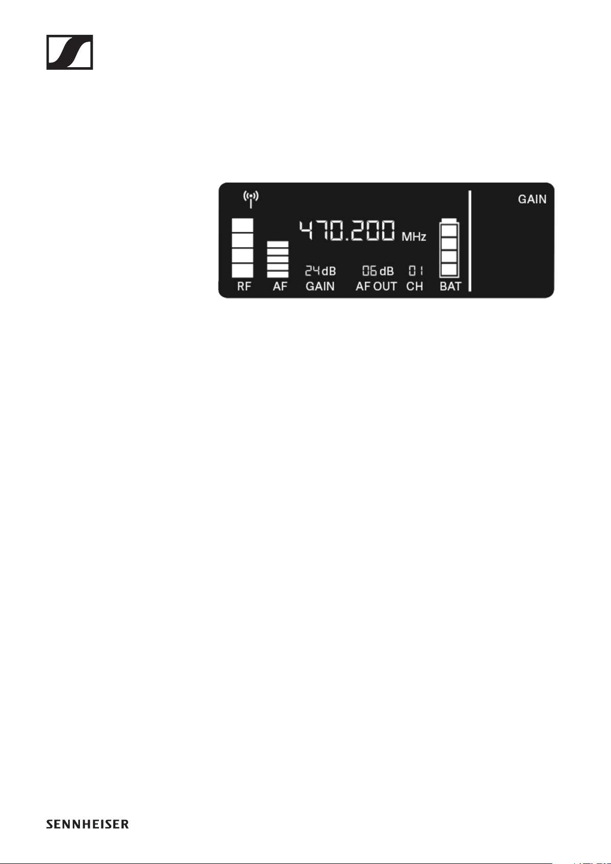
GAIN menu item
Under the GAIN menu item, you can set the level of the audio
signal coming from the coupled transmitter (e.g. vocals via
EW-D SKM-S or guitar via EW-D SK).
▷Open the GAIN menu item.
The item flashes on the display as follows.
►
▷Press the UP or DOWN button to adjust the value.
Make sure that the level indicator AF on the display is not
too high. The LINK LED flashes yellow when the signal is
overdriven.
▷Press the SET button to save the set value.
Recommended settings for a unity gain link:
Unity gain refers to the configuration where the audio signal
arriving at a device leaves the device with the same level.
Example: If you are using an EW-D wireless link instead of a
guitar cable, with unity gain settings, the volume of the guitar
in the guitar amplifier will be as high as it would be if using a
guitar cable.
Possible unity gain settings:
▷
AF Out 18 dB | Gain 27 dB
▷AF Out 12 dB | Gain 33 dB
▷AF Out 6 dB | Gain 39 dB
AF OUT menu item
Under the AF OUT menu item, you can set the level of the au-
dio signal coming from the receiver’s audio outputs (AF out
Bal/Unbal). This audio signal can be output to a mixing con-
sole or an amplifier, for example.
▷Open the AF OUT menu item.
The item flashes on the display as follows.
EW-D EM rack receiver
62
►
▷Press the UP or DOWN button to adjust the value.
Make sure that the signal in the next device in the signal
chain (e.g. mixing console, power amplifier, guitar amplifi-
er, etc.) is not overdriven.
▷Press the SET button to save the set value.
Recommended settings for a unity gain link:
Unity gain refers to the configuration where the audio signal
arriving at a device leaves the device with the same level.
Example: If you are using an EW-D wireless link instead of a
guitar cable, with unity gain settings, the volume of the guitar
in the guitar amplifier will be as high as it would be if using a
guitar cable.
Possible unity gain settings:
▷
AF Out 18 dB | Gain 27 dB
▷
AF Out 12 dB | Gain 33 dB
▷AF Out 6 dB | Gain 39 dB
MUTE LOCK menu item
Under the MUTE LOCK menu item, you can disable the mute
switch on the paired transmitter.
The transmitter can then no longer be muted.
▷Open the MUTE LOCK menu item.
The item flashes on the display as follows.
►
▷Press the UP or DOWN button to enable or disable the
function.
If the following icon appears on the display, the transmit-
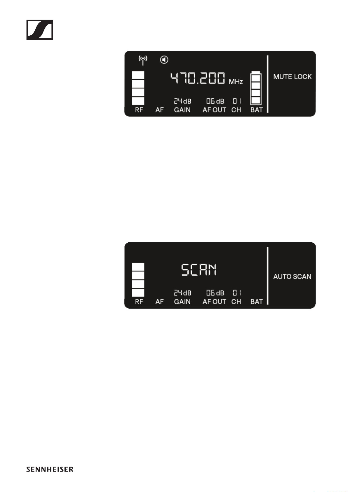
EW-D EM rack receiver
63
ter’s mute switch is disabled.
►
▷Press the SET button to save the set value.
AUTO SCAN menu item
Under the AUTO SCAN menu item, you can perform an auto-
matic frequency scan of your area. This enables you to easily
find and assign free radio frequencies.
The scan starts at the lowest frequency in the device’s fre-
quency range.
▷Open the AUTO SCAN menu item.
The scan starts automatically. The next free frequency is
shown on the display.
►
▷Press the SET button to accept the displayed frequency.
or
▷Press the UP or DOWN button to display the next free fre-
quency.
or
▷Press the ESC button to cancel the scan.
The previous frequency remains unchanged.
If you have set a new frequency, you must still synchronize
the receiver with the transmitter to establish the radio link
(see "Establishing a radio link | Synchronizing the receiver and
transmitter").

EW-D EM rack receiver
64
CHANNEL menu item
Under the CHANNEL menu item, you can set the radio fre-
quency by selecting a preset channel.
If you are not sure whether the selected frequency is free, we
recommend performing a scan to detect all free frequencies:
"AUTO SCAN menu item".
▷Open the CHANNEL menu item.
The item flashes on the display as follows.
►
▷Press the UP or DOWN button to select a preset channel.
▷Press the SET button to accept the displayed frequency.
or
▷Press the ESC button to cancel the setting.
The previous frequency remains unchanged.
If you have set a new frequency, you must still synchronize
the receiver with the transmitter to establish the radio link
(see "Establishing a radio link | Synchronizing the receiver and
transmitter").
EW-D EM rack receiver
65
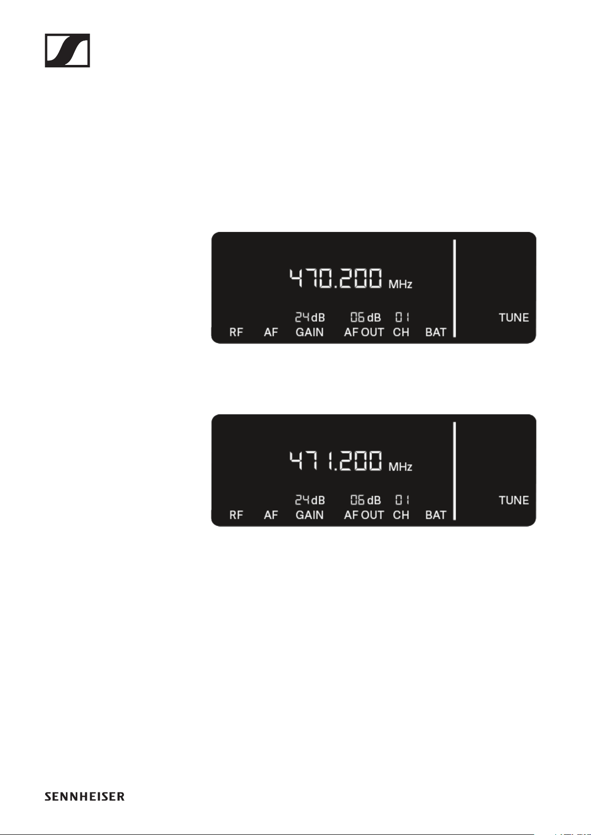
TUNE menu item
Under the TUNE menu item, you can manually set the radio
frequency independently of the preset channels.
If you are not sure whether the selected frequency is free, we
recommend performing a scan to detect all free frequencies:
"AUTO SCAN menu item".
▷Open the TUNE menu item.
The item flashes on the display as follows.
►
▷Press the UP or DOWN button to set the frequency in the
megahertz range.
▷Press the SET button to save the set value.
The item flashes on the display as follows.
►
▷Press the UP or DOWN buttons to finely adjust the frequen-
cy in the kilohertz range.
▷Press the SET button to accept the displayed frequency.
or
▷Press the ESC button to cancel the setting.
The previous frequency remains unchanged.
If you have set a new frequency, you must still synchronize
the receiver with the transmitter to establish the radio link
(see "Establishing a radio link | Synchronizing the receiver and
transmitter").
EW-D EM rack receiver
66
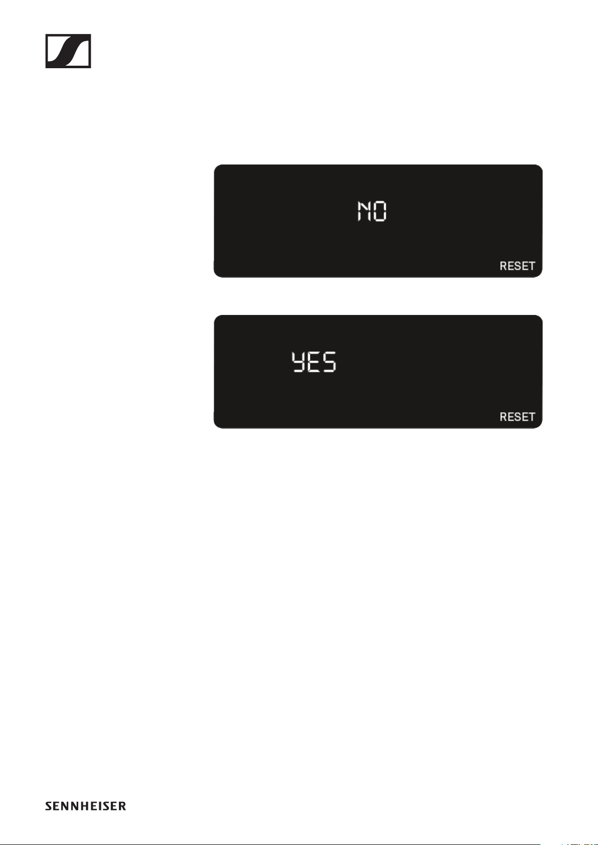
RESET menu item
Under the RESET menu item, you can reset the receiver to its
factory settings.
▷Open the RESET menu item.
The item flashes on the display as follows.
►
▷Press the UP or DOWN button to switch between the op-
tions
YES and NO.
►
YES: The receiver is reset to its factory settings.
NO: The receiver is not reset.
▷Press the SET button to save the set value.
EW-D EM rack receiver
67
Using EW-D Color Coding Sets to label trans-
mission paths
You can use the EW-D Color Coding Sets (see "Color Coding
Sets") to identify which transmitters belong to which receiv-
ers. This makes it easier to match up the individual devices,
especially in multi-channel systems.
You can also assign colors to the devices in the EW-D Smart
Assist app.
EW-D SKM-S handheld transmitter
68
EW-D SKM-S handheld transmitter
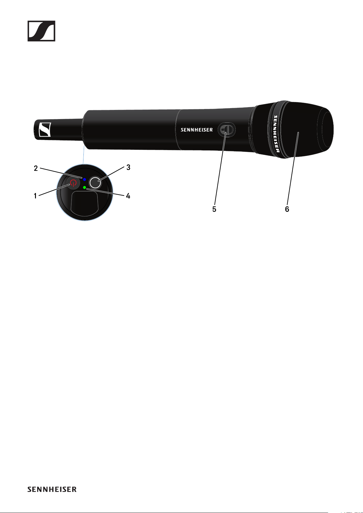
Product overview
►
1ON/OFF button
•See "Switching the handheld transmitter on and off"
2DATA LED
•See "Meaning of the LEDs"
3SYNC button
•See "Establishing a radio link | Synchronizing the receiver
and transmitter"
4LINK LED
•See "Meaning of the LEDs"
5Mute switch
•See "Muting the handheld transmitter"
6Microphone module
•See "Replacing the microphone module"
EW-D SKM-S handheld transmitter
69
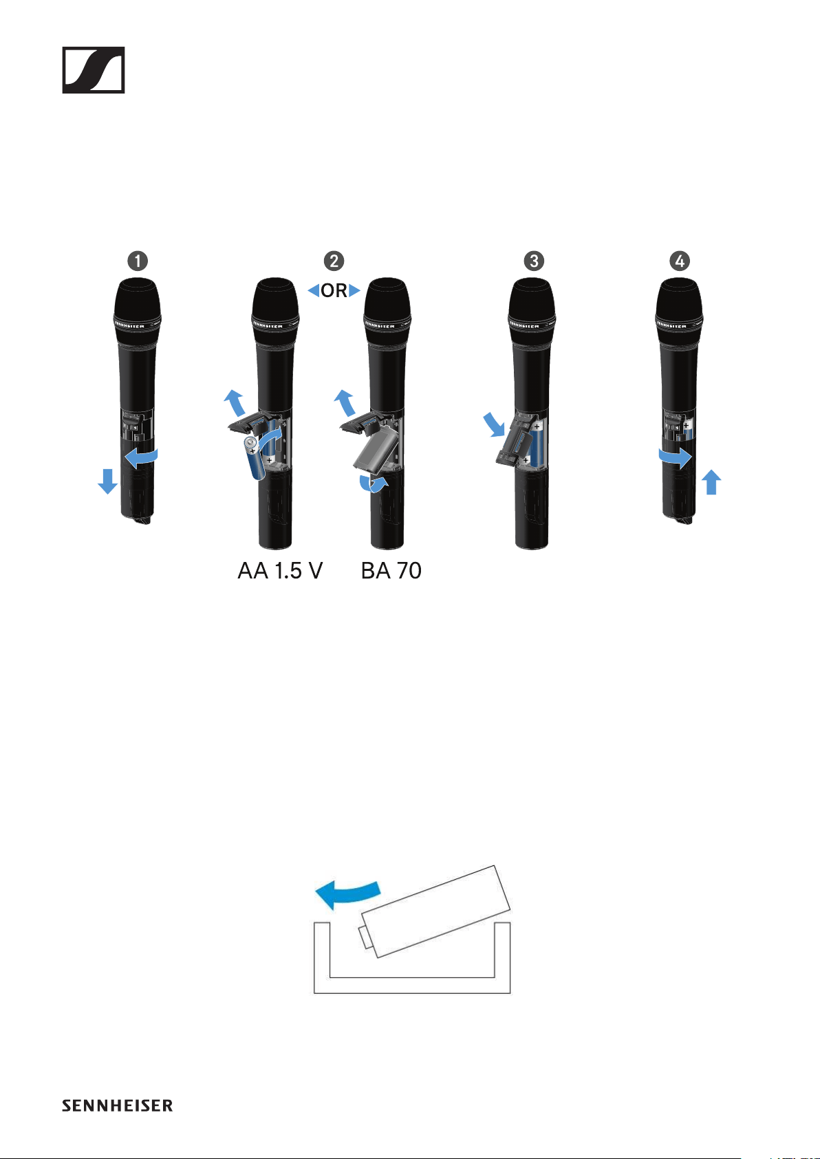
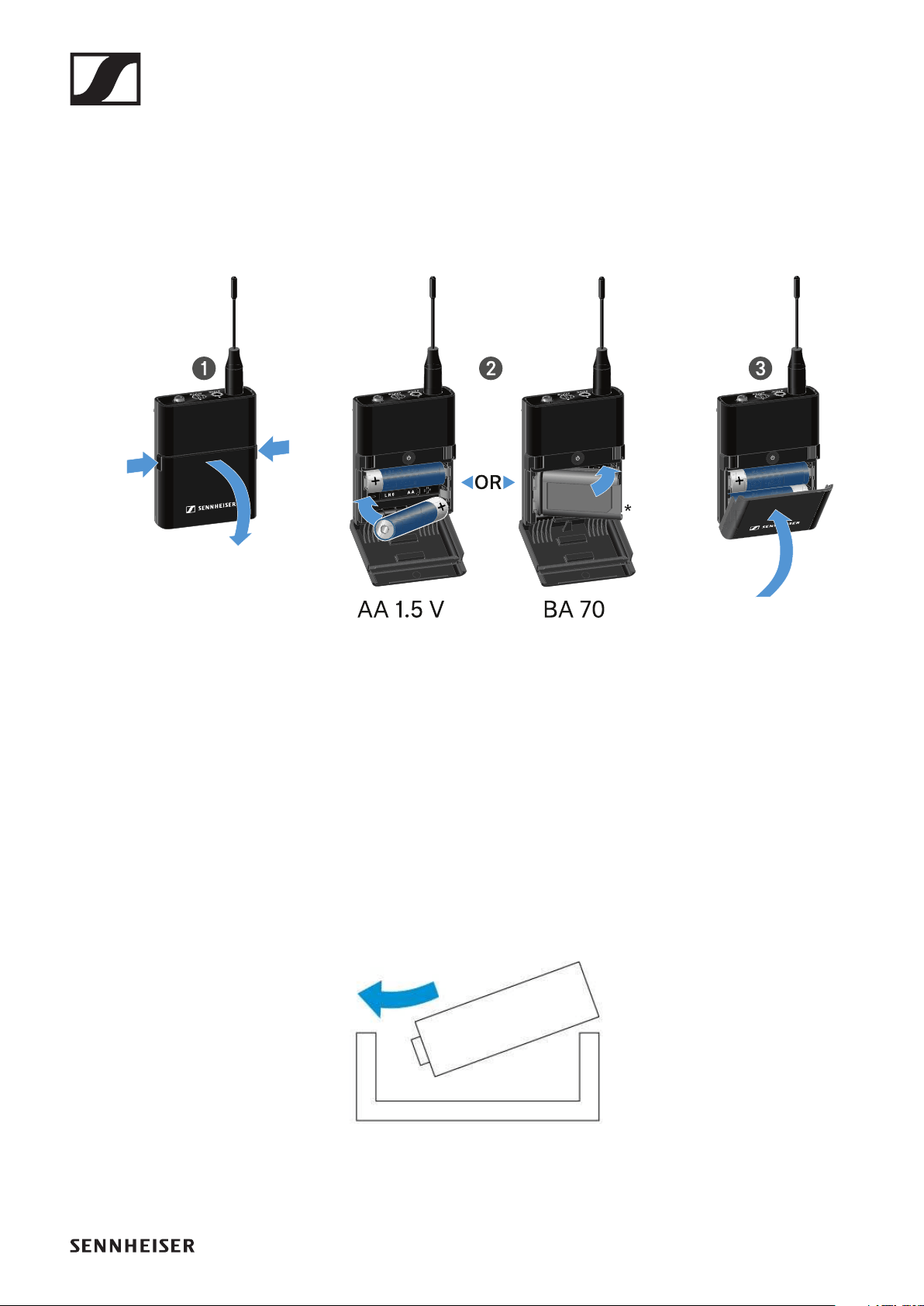
Inserting and removing the batteries/re-
chargeable batteries
You can operate the handheld transmitter either with batteries
(AA, 1.5 V) or with the rechargeable Sennheiser BA 70 battery.
▷Unscrew the microphone housing as shown in the figure
and pull it down as far as it will go.
▷Insert the batteries or the BA 70 rechargeable battery as in-
dicated in the battery compartment. Observe correct polar-
ity.
▷Screw the microphone housing back on.
Note about the BA 70 rechargeable battery
▷Make sure that the BA 70 rechargeable battery is inserted
as follows:
►

EW-D SKM-S handheld transmitter
70
Replacing the microphone module
To replace the microphone module:
▷Unscrew the microphone module.
▷Screw the desired microphone module on.
▷Do not touch the wireless microphone contacts or the mi-
crophone module contacts. If you touch the contacts, they
may become dirty or bent.
►
Compatible microphone modules
The following microphone modules are compatible with the
handheld transmitter:
•MMD 835-1 | Dynamic microphone module with cardioid
pattern
•MMD 845-1 | Dynamic microphone module with super-car-
dioid pick-up pattern
•MME 865-1 | Condenser microphone module with super-
cardioid pick-up pattern
•MMD 935-1 | Dynamic microphone module with cardioid
pattern

EW-D SKM-S handheld transmitter
71
•MMD 945-1 | Dynamic microphone module with super-car-
dioid pick-up pattern
•MMK 965-1 | Condenser microphone module with select-
able pattern: cardioid and super-cardioid
•MMD 42-1 | Dynamic microphone module with omni-direc-
tional pattern
•Neumann KK 204 | Condenser microphone module with
cardioid pattern
•Neumann KK 205 | Condenser microphone module with su-
per-cardioid pick-up pattern
•MM 435 | Dynamic microphone module with cardioid pat-
tern
•MM 445 | Dynamic microphone module with super-cardioid
pick-up pattern
•ME 9002 | Condenser microphone module with omni-direc-
tional pattern
•ME 9004 | Condenser microphone module with cardioid
pattern
•ME 9005 | Condenser microphone module with super-car-
dioid pick-up pattern

EW-D SKM-S handheld transmitter
72
Using EW-D Color Coding Sets to label trans-
mission paths
You can use the EW-D Color Coding Sets (see "Color Coding
Sets") to identify which transmitters belong to which receiv-
ers. This makes it easier to match up the individual devices,
especially in multi-channel systems.
You can also assign colors to the devices in the EW-D Smart
Assist app.
EW-D SKM-S handheld transmitter
73
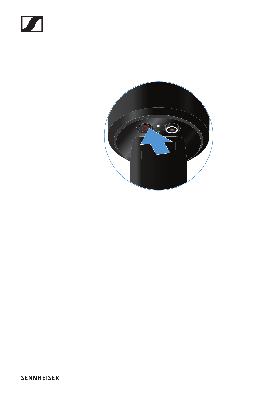
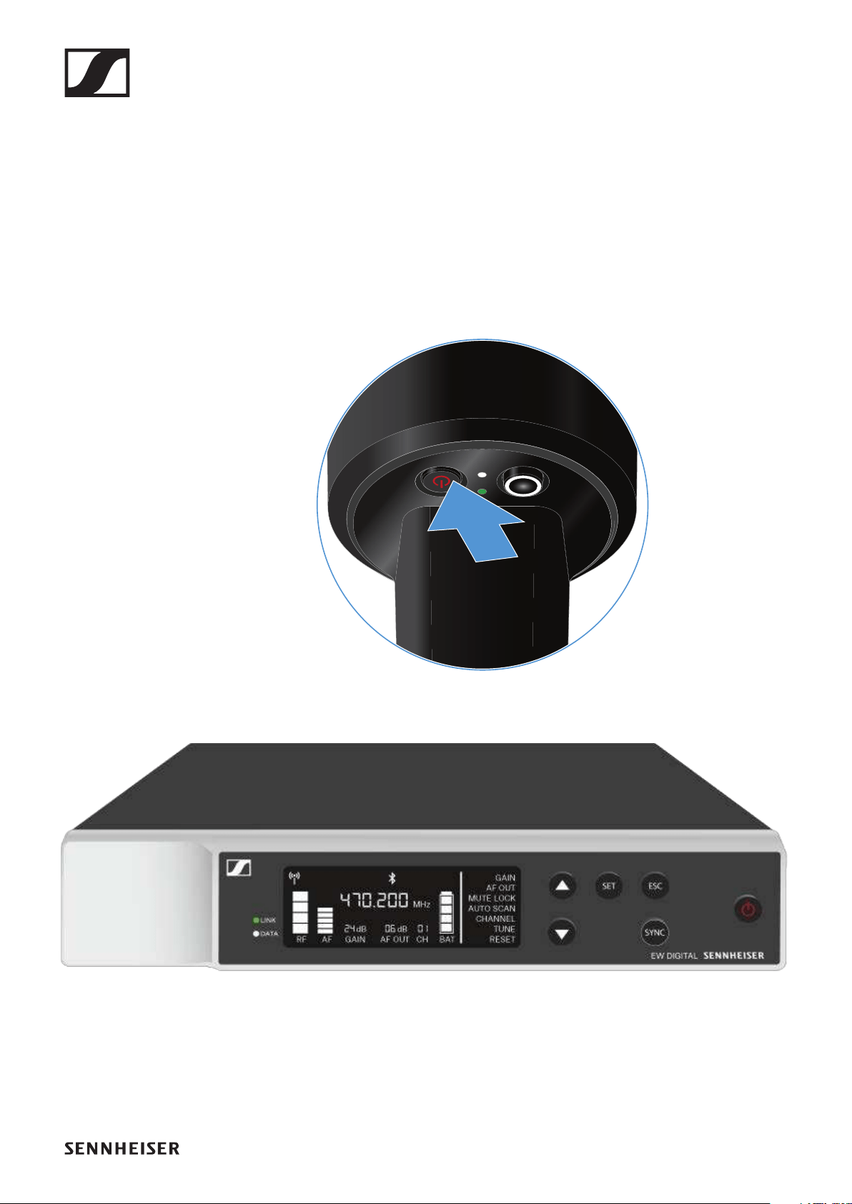
Switching the handheld transmitter on and
off
To switch the handheld transmitter on:
▷Short-press the ON/OFF button.
The LINK LED lights up and the transmitter switches on.
►
To switch the handheld transmitter off:
▷Hold down the ON/OFF button until the LEDs switch off.
EW-D SKM-S handheld transmitter
74
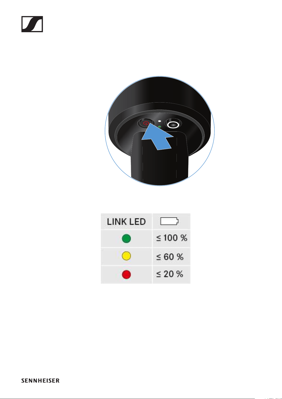
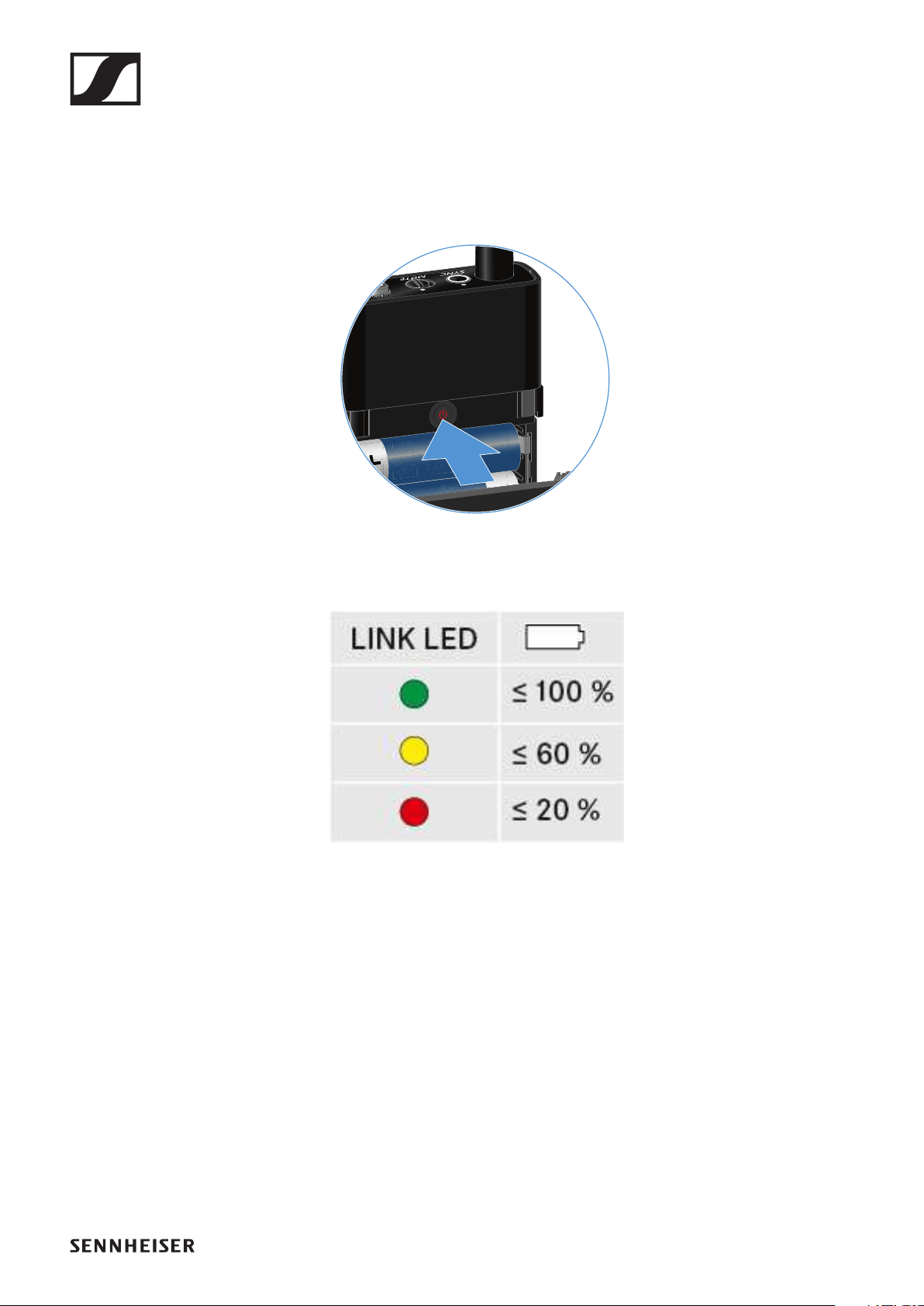
Checking the battery status of the transmit-
ter (Check function)
To check the battery status of the transmitter:
▷Short-press the ON/OFF button on the transmitter.
►
The transmitter’s LINK LED flashes to indicate the current
charge level of the battery or the BA 70 rechargeable battery.
►
Pressing the transmitter’s ON/OFF button will simultaneously
trigger the Identify function: "Identifying the paired receiver
(Identify function)".
EW-D SKM-S handheld transmitter
75
Identifying the paired receiver (Identify func-
tion)
In multi-channel systems, you can use the Check function to
quickly identify to which receiver the transmitter is paired.
Both the transmitter and receiver must be switched on.
▷Short-press the ON/OFF button on the transmitter.
►
The display on the paired receiver starts flashing.
►
Pressing the transmitter’s ON/OFF button will simultaneously
trigger the Check function: "Checking the battery status of the
transmitter (Check function)".

EW-D SKM-S handheld transmitter
76
Meaning of the LEDs
The LINK and DATA LEDs on the bottom of the transmitter can
indicate the following information.
LINK LED
The LINK LED provides information about the status of the ra-
dio link between the transmitter and receiver, as well as status
information for the transmitter.
The LED is green:
▷The transmission frequency is active.
The LED is yellow:
▷The link between the transmitter and receiver is estab-
lished.
▷The audio signal is muted.
or
▷No microphone module is mounted on the SKM-S handheld
transmitter.
The LED is flashing yellow:
▷The link between the transmitter and receiver is estab-
lished.
▷The audio signal is overdriven (clipping).

EW-D SKM-S handheld transmitter
77
The LED is continuously red:
▷The (rechargeable) battery in the transmitter is dead.
The LED is flashing red:
▷The link between the transmitter and receiver is estab-
lished.
▷The battery/rechargeable battery in the transmitter is low.
The LED is off:
▷No link between the transmitter and receiver.
▷The transmitter is switched off.
DATA LED
The DATA LED provides information about the synchroniza-
tion of transmitters and receivers.
The LED is flashing blue:
▷The transmitter is being synchronized with a receiver.
The LED is continuously blue:
▷The firmware is being updated.
The LED is off:
▷There is currently no active data link.

EW-D SKM-S handheld transmitter
78
Establishing a connection to the receiver
To establish a radio link between the transmitter and the re-
ceiver, the devices must be synchronized.
See "Establishing a radio link | Synchronizing the receiver and
transmitter".
Conditions and restrictions for using frequencies
There may be special conditions and restrictions for using fre-
quencies in your country.
Before putting the product into operation, find the information
for your country at the following address:
www.sennheiser.com/sifa
EW-D SKM-S handheld transmitter
79
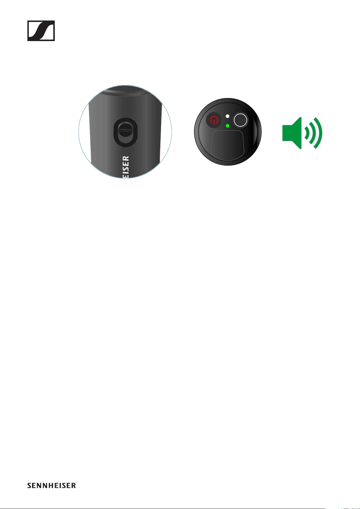
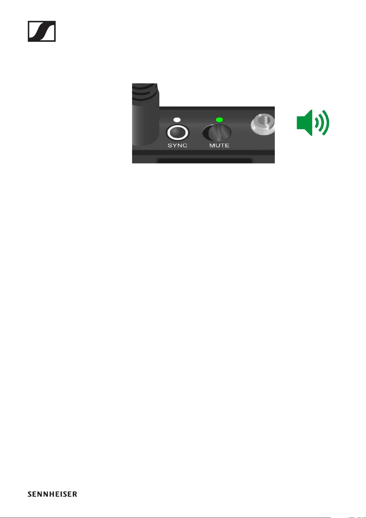
Muting the handheld transmitter
You can mute the audio signal using the mute switch.
►
▷Slide the mute switch to the desired position to mute or ac-
tivate the audio signal.
You can disable the mute switch by activating the MUTE
LOCK option on the receiver (see "MUTE LOCK menu item").
EW-D SK bodypack transmitter
80
EW-D SK bodypack transmitter
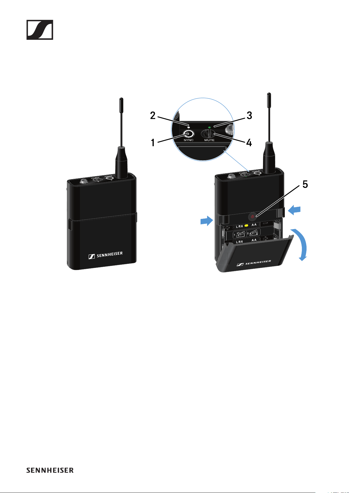
Product overview
►
1SYNC button
•See "Establishing a radio link | Synchronizing the receiver
and transmitter"
2DATA LED
•See "Meaning of the LEDs"
3LINK LED
•See "Meaning of the LEDs"
4Mute switch
•See "Muting the bodypack transmitter"
5ON/OFF button
•See "Switching the bodypack transmitter on and off"
EW-D SK bodypack transmitter
81
Inserting and removing the batteries/re-
chargeable batteries
You can operate the bodypack transmitter either with batter-
ies (AA, 1.5 V) or with the rechargeable Sennheiser BA 70 bat-
tery.
▷Press the two catches and open the battery compartment
cover.
▷Insert the batteries or the BA 70 rechargeable battery as in-
dicated in the battery compartment. Observe correct polar-
ity.
▷Close the battery compartment.
The cover locks into place with an audible click.
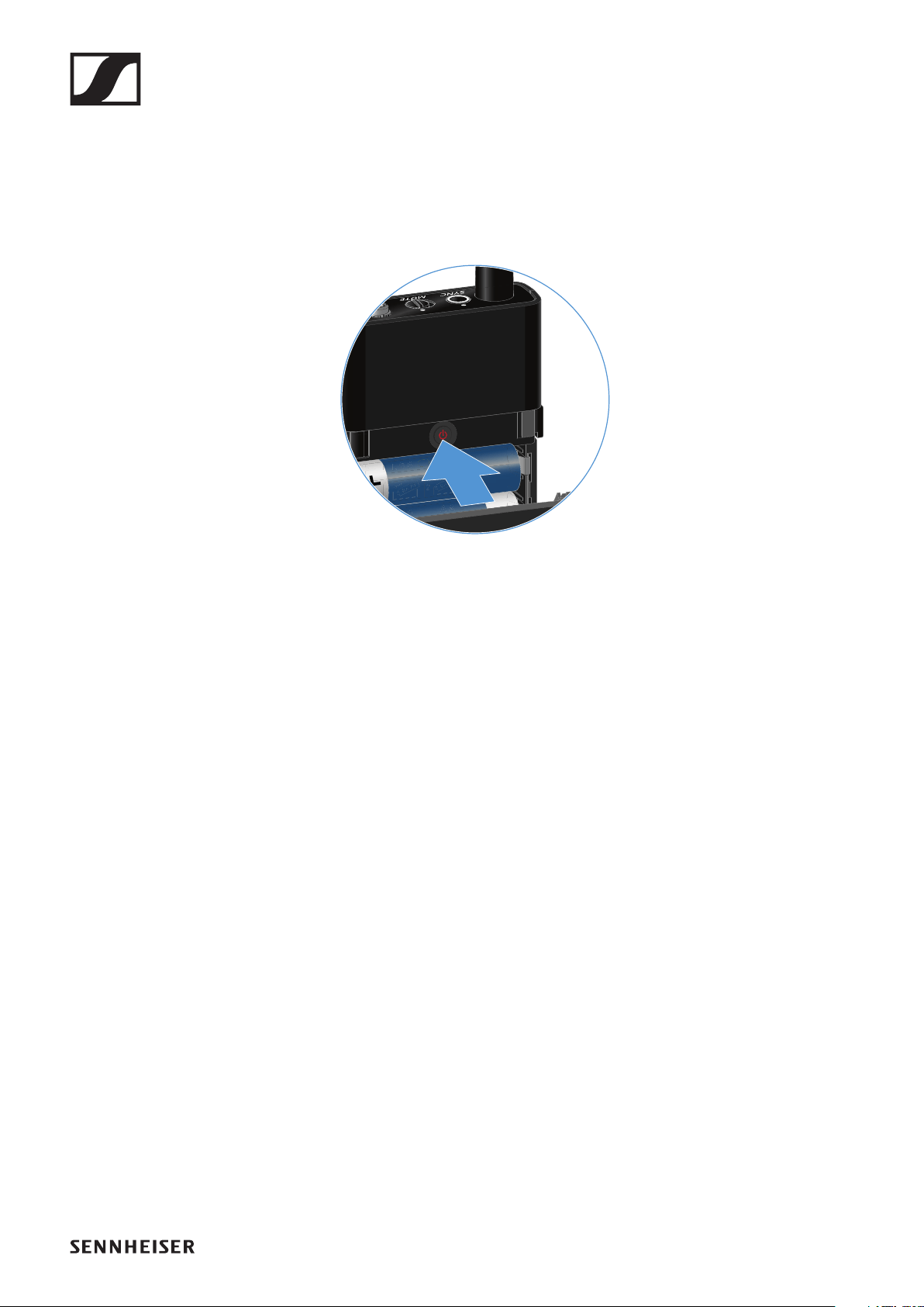
Note about the BA 70 rechargeable battery
▷Make sure that the BA 70 rechargeable battery is inserted
as follows:
►
EW-D SK bodypack transmitter
82
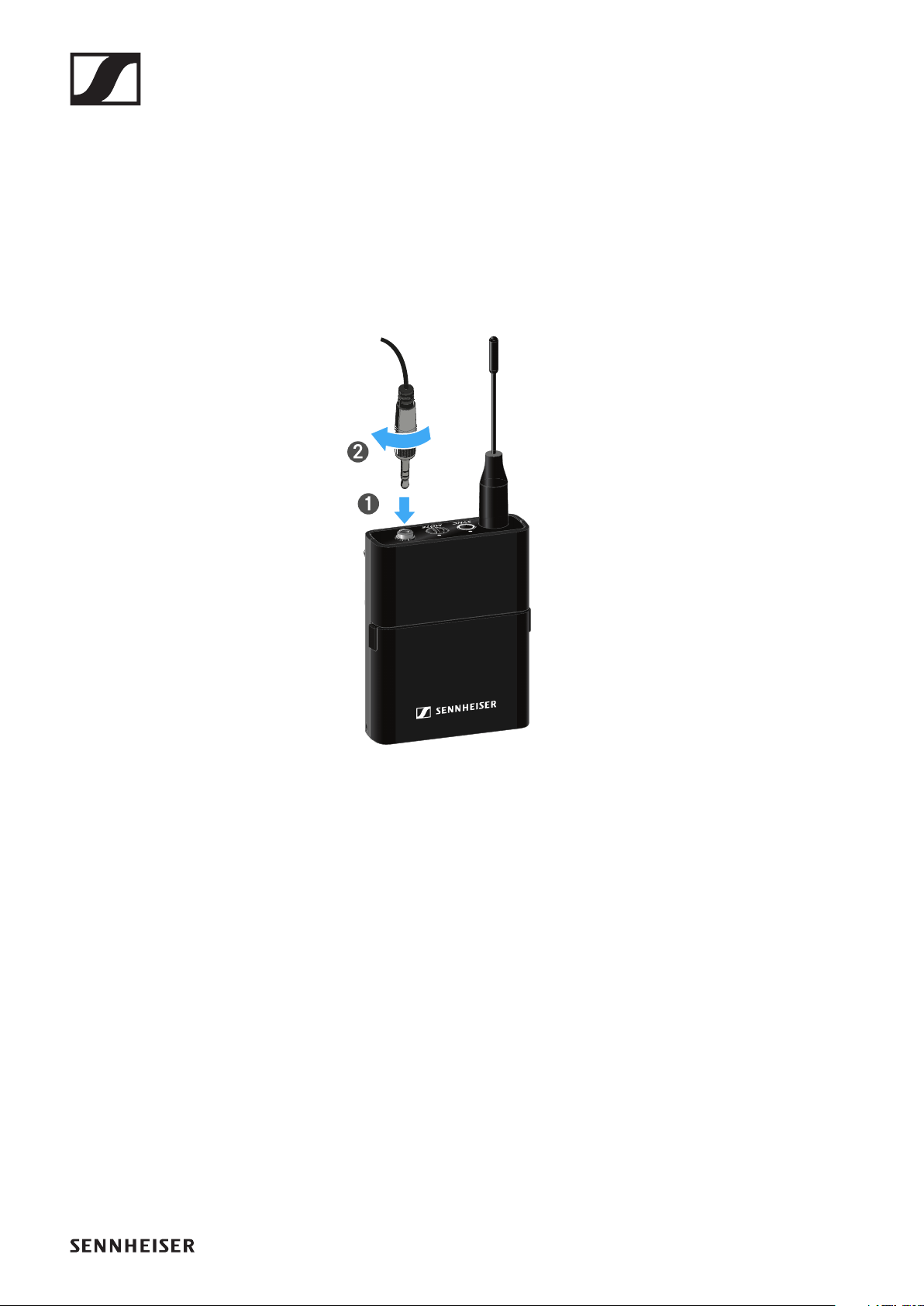
Connecting a microphone to the bodypack
transmitter
To connect a microphone to the bodypack transmitter:
▷Insert the cable’s 3.5 mm jack plug into the socket on the
bodypack transmitter as shown in the diagram.
▷Screw the plug’s coupling ring onto the audio socket thread
of the bodypack transmitter.
Compatible microphones
The following microphones are compatible with the bodypack
transmitter:
Lavalier microphones:
•ME 2 | Lavalier microphone with omni-directional pattern
(models from 2021 and later with gold-plated plug*)
•ME 4 | Lavalier microphone with cardioid pattern (models
from 2021 and later with gold-plated plug*)
•MKE Essential Omni | Lavalier microphone with omni-di-
rectional pattern
•MKE 2 Gold | Lavalier microphone with omni-directional
pattern (models from 2018 and later with blue serial number
label)
•MKE 1 | Lavalier microphone with omni-directional pattern

EW-D SK bodypack transmitter
83
Headset microphones:
•ME 3 | Headset microphone with cardioid pattern (models
from 2021 and later with gold-plated plug*)
•HSP Essential Omni | Headset microphone with omni-di-
rectional pattern
•HSP 2 | Headset microphone with omni-directional pattern
(models from March 2020 and later with code 1090 or high-
er)
•HS 2 | Headset microphone with omni-directional pattern
(models from 2021 and later with gold-plated plug*)
•SL Headmic 1 | Headset microphone with omni-directional
pattern
*Pre-2021 models with a nickel plug are not recommended.
They can pick up noise if they are placed too close to the trans-
mitter.
EW-D SK bodypack transmitter
84
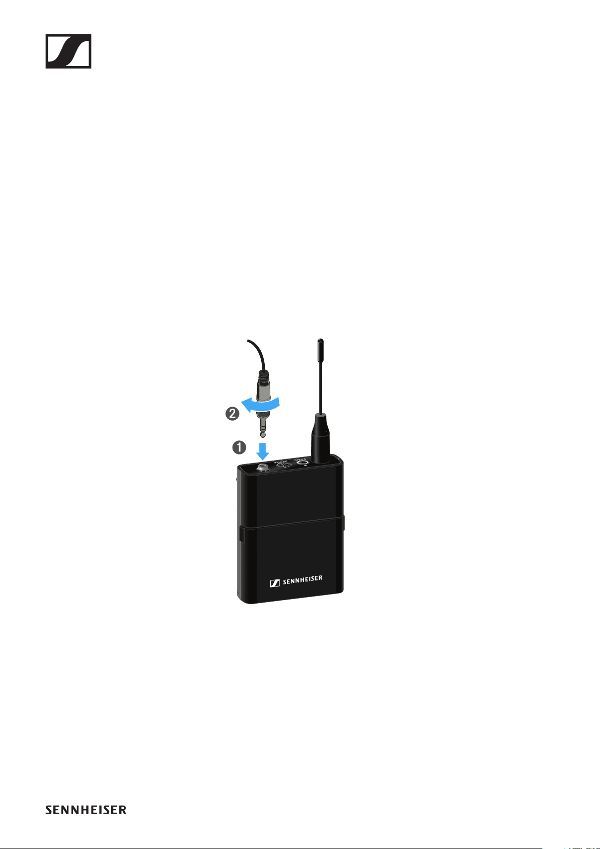
Connecting an instrument or line source to
the bodypack transmitter
You can connect instruments or audio sources with a line level
to the bodypack transmitter.
To do this, you will need the CI 1 (6.3 mm jack plug on a lock-
able 3.5 mm jack plug) or CL 2 (XLR-3F plug on a lockable 3.5
mm jack plug) Sennheiser cables.
To connect an instrument or line source to bodypack transmit-
ter:
▷Insert the cable’s 3.5 mm jack plug into the socket on the
bodypack transmitter as shown in the diagram.
▷Screw the plug’s coupling ring onto the audio socket thread
of the bodypack transmitter.

EW-D SK bodypack transmitter
85
Using EW-D Color Coding Sets to label trans-
mission paths
You can use the EW-D Color Coding Sets (see "Color Coding
Sets") to identify which transmitters belong to which receiv-
ers. This makes it easier to match up the individual devices,
especially in multi-channel systems.
You can also assign colors to the devices in the EW-D Smart
Assist app.

EW-D SK bodypack transmitter
86
Changing the belt clip
You can change the belt clip on the bodypack transmitter or
flip it over depending on how you want to wear it.
To remove the belt clip:
▷Carefully loosen the belt clip with a small screwdriver as
shown in the figure.
▷Be very careful not to scratch the housing.
To insert the belt clip:
▷Insert one side of the belt clip first as shown in the figure.
▷Then insert the second side of the belt clip.
▷Gently press the belt clip all the way in on both sides.
▷Always insert one side before the other, not at the same
time, as otherwise the belt clip could bend.
EW-D SK bodypack transmitter
87
Switching the bodypack transmitter on and
off
To switch the bodypack transmitter on:
▷Short-press the ON/OFF button.
The LINK LED lights up and the transmitter switches on.
►
To switch the bodypack transmitter off:
▷Hold down the ON/OFF button until the LEDs switch off.
EW-D SK bodypack transmitter
88
Checking the battery status of the transmit-
ter (Check function)
To check the battery status of the transmitter:
▷Short-press the ON/OFF button on the transmitter.
►
The transmitter’s LINK LED flashes to indicate the current
charge level of the battery or the BA 70 rechargeable battery.
►
Pressing the transmitter’s ON/OFF button will simultaneously
trigger the Identify function: "Identifying the paired receiver
(Identify function)".

EW-D SK bodypack transmitter
89
Identifying the paired receiver (Identify func-
tion)
In multi-channel systems, you can use the Check function to
quickly identify to which receiver the transmitter is paired.
Both the transmitter and receiver must be switched on.
▷Short-press the ON/OFF button on the transmitter.
►
The display on the paired receiver starts flashing.
►
Pressing the transmitter’s ON/OFF button will simultaneously
trigger the Check function: "Checking the battery status of the
transmitter (Check function)".

EW-D SK bodypack transmitter
90
Meaning of the LEDs
The LINK and DATA LEDs on the top of the transmitter can in-
dicate the following information.
LINK LED
The LINK LED provides information about the status of the ra-
dio link between the transmitter and receiver, as well as status
information for the transmitter.
The LED is green:
▷The transmission frequency is active.
The LED is yellow:
▷The link between the transmitter and receiver is estab-
lished.
▷The audio signal is muted.
The LED is flashing yellow:
▷The link between the transmitter and receiver is estab-
lished.
▷The audio signal is overdriven (clipping).

EW-D SK bodypack transmitter
91
The LED is continuously red:
▷The (rechargeable) battery in the transmitter is dead.
The LED is flashing red:
▷The link between the transmitter and receiver is estab-
lished.
▷The battery/rechargeable battery in the transmitter is low.
The LED is off:
▷No link between the transmitter and receiver.
▷The transmitter is switched off.
DATA LED
The DATA LED provides information about the synchroniza-
tion of transmitters and receivers.
The LED is flashing blue:
▷The transmitter is being synchronized with a receiver.
The LED is continuously blue:
▷The firmware is being updated.
The LED is off:
▷There is currently no active data link.

EW-D SK bodypack transmitter
92
Establishing a connection to the receiver
To establish a radio link between the transmitter and the re-
ceiver, the devices must be synchronized.
See "Establishing a radio link | Synchronizing the receiver and
transmitter".
Conditions and restrictions for using frequencies
There may be special conditions and restrictions for using fre-
quencies in your country.
Before putting the product into operation, find the information
for your country at the following address:
www.sennheiser.com/sifa
EW-D SK bodypack transmitter
93
Muting the bodypack transmitter
You can mute the audio signal using the mute switch.
►
▷Slide the mute switch to the desired position to mute or ac-
tivate the audio signal.
You can disable the mute switch by activating the MUTE
LOCK option on the receiver (see "MUTE LOCK menu
item").
EW-DX EM 2 rack receiver
94
EW-DX EM 2 rack receiver
Product overview
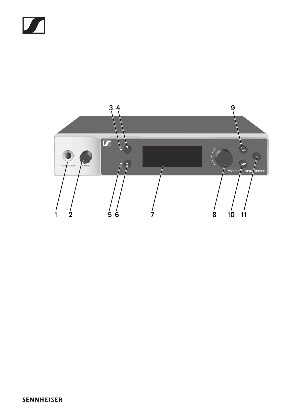
Front
1Headphone socket
•See "Using the headphone output"
2Volume control for the headphone socket
•See "Using the headphone output"
3CH 1 LED to indicate the status of channel 1
•See "Meaning of the LEDs"
4CH 1 button for selecting channel 1
•See "Displays on the receiver’s display panel"
•See "Buttons for navigating the menu"
5CH 2 LED to indicate the status of channel 1
•See "Meaning of the LEDs"
6CH 2 button for selecting channel 1
•See "Displays on the receiver’s display panel"
•See "Buttons for navigating the menu"
7Display for status information and operating menu
•See "Displays on the receiver’s display panel"
EW-DX EM 2 rack receiver
95
8Jog dial (UP/DOWN/SET) for navigating the operating
menu
•See "Buttons for navigating the menu"
9ESC button for canceling an action in the menu
•See "Buttons for navigating the menu"
10SYNC button for synchronizing the transmitter and receiver
•See "Establishing a radio link | Synchronizing the receiver
and transmitter"
11ON/OFF button for switching the device on and off
•See "Switching the receiver on and off"
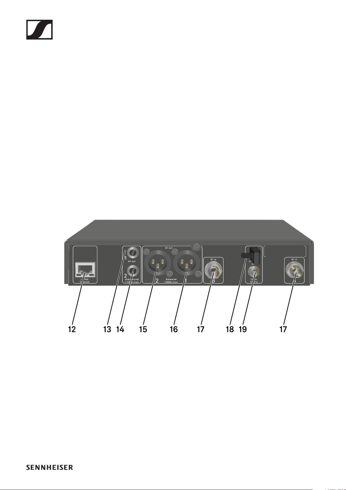
Back
12 PoE/Ethernet RJ-45 socket for controlling the device over
the network and for Power over Ethernet power supply
•See "Connecting receivers in a network"
•See "Connecting/disconnecting the receiver to/from the
power supply system"
136.3 mm jack socket for AF out Unbalanced audio output for
channel 1
•See "Outputting audio signals"
146.3 mm jack socket for AF out Unbalanced audio output for
channel 2
•See "Outputting audio signals"

EW-DX EM 2 rack receiver
96
15XLR-3 socket for AF out Balanced audio output for channel
2
•See "Outputting audio signals"
16XLR-3 socket for AF out Balanced audio output for channel
1
•See "Outputting audio signals"
17 BNC sockets ANT 1 RF in and ANT 2 RF in for antenna inputs
•See "Connecting antennas"
18Strain relief for the connection cable of the power supply
unit
•See "Connecting/disconnecting the receiver to/from the
power supply system"
19DC in connection socket for the power supply unit
•See "Connecting/disconnecting the receiver to/from the
power supply system"
EW-DX EM 2 rack receiver
97
Connecting/disconnecting the receiver to/
from the power supply system
You can operate the receiver using either the included power
supply unit or with Power over Ethernet (PoE IEEE 802.3af
Class 0). Please refer to the following information.
Power from the power supply unit
If using a power supply unit, use only the power supply unit in-
cluded with the device. It is designed for your receiver and en-
sures safe operation.
You will find the power supply unit and the country adapters in
the packaging under the tray:
To connect the receiver to the power supply system:
▷Insert the plug of the power supply unit into the DC in sock-
et on the receiver.
▷Pass the cable of the power supply unit through the strain
relief.
▷Slide the supplied country adapter onto the power supply
unit.
▷Plug the power supply unit into the wall socket.
Rack mount angles
Power supply unit
Power supply adapters
EW-DX EM 2 rack receiver
98
To completely disconnect the receiver from the power supply
system:
▷Unplug the power supply unit from the wall socket.
▷Unplug the power supply unit from the DC in socket on the
receiver.
EW-DX EM 2 rack receiver
99
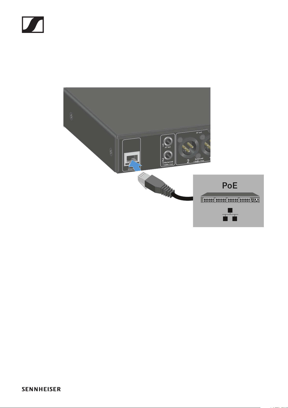
Power over Ethernet (PoE)
The receiver can be powered via Power over Ethernet (PoE
IEEE 802.3af Class 0).
▷Connect the receiver to a PoE-enabled network switch.
EW-DX EM 2 rack receiver
100
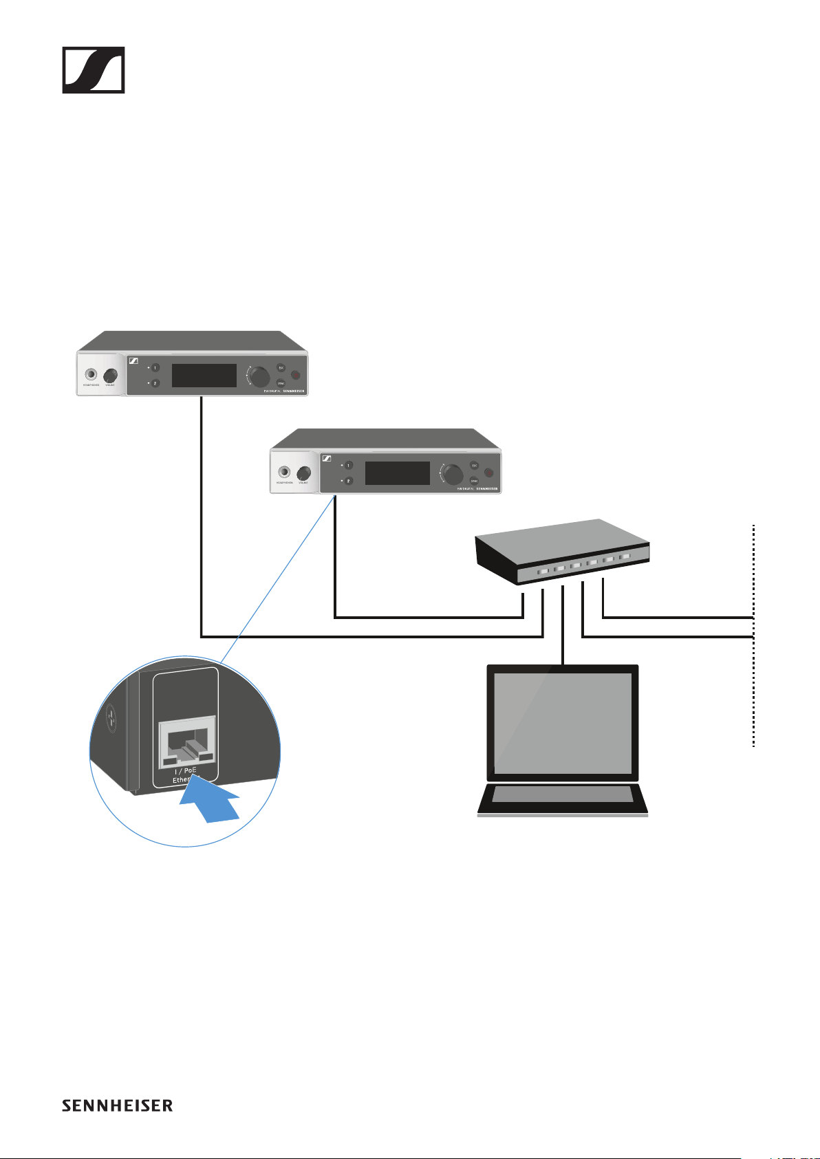
Connecting receivers in a network
You can monitor and control one or more receivers via a net-
work connection using the Sennheiser Wireless Systems
Manager (WSM) or Sennheiser Control Cockpit (SCC) soft-
ware.
The network does not have to be a homogeneous network in-
cluding only receivers. You can integrate the receiver into your
existing network infrastructure with any other types of devic-
es.
For more information about controlling devices via the Senn-
heiser Wireless Systems Manager or Sennheiser Control
Cockpit software, refer to the instruction manual for the soft-
ware. You can download the software here:
www.sennheiser.com/wsm
www.sennheiser.com/control-cockpit-software
EW-DX EM 2 rack receiver
101
Connecting antennas
Connecting rod antennas
To connect the supplied rod antennas:
►
▷Connect the antennas to the two antenna inputs on the re-
ceiver as shown in the figure.
▷Slightly angle the antennas to the left and right as shown in
the figure.
If you are using more than one receiver, we recommend
using remote antennas and possibly the EW-D ASA anten-
na splitter ("EW-D ASA antenna splitter").
EW-DX EM 2 rack receiver
102
Connecting remote antennas
To connect remote antennas:
►
▷Connect the antennas to the two antenna inputs on the re-
ceiver as shown in the figure.
▷Observe the specified minimum spacing.
*Recommended antennas:
•ADP UHF | 470 – 1075 MHz
•AD 1800 | 1400 – 2400 MHz
If you are using more than one receiver, we recommend using
remote antennas and possibly the EW-D ASA antenna splitter
("EW-D ASA antenna splitter").
EW-DX EM 2 rack receiver
103
Outputting audio signals
Each of the two channels on the EW-DX EM 2 has both a bal-
anced XLR-3M output socket and an unbalanced 6.3 mm (1/4")
jack output socket.
▷Always use only one of the two output sockets for each
channel.
To connect an XLR cable:
▷Plug the XLR cable into the AF out Balanced socket for the
respective channel on the EW-DX EM 2.
To connect a jack cable:
▷Plug the jack cable into the AF out Unbalanced socket for
the respective channel on the EW-DX EM 2.
EW-DX EM 2 rack receiver
104
Installing receivers in a rack
Observe the following instructions when mounting the receiv-
er in a rack.
The mounting brackets for installing the receiver in the rack
can be found in the packaging under the tray:
CAUTION!
Rack mounting poses risks
When installing the device in a closed 19" rack or multi-rack
assembly, please consider that, during operation, the ambient
temperature, the mechanical load and the electrical potentials
will be different from those of devices which are not mounted
into a rack.
▷Make sure that the ambient temperature within the rack
does not exceed the permissible temperature limit stated
in the specifications. See "SPECIFICATIONS".
▷Ensure sufficient ventilation; if necessary, provide addi-
tional ventilation.
▷Make sure that the mechanical load of the rack is even.
▷When connecting to the power supply system, observe the
information indicated on the type plate. Avoid overloading
the circuits. If necessary, provide overcurrent protection.
▷When mounting in a rack, please note that intrinsically
harmless leakage currents of the individual power supply
units may accumulate, thereby exceeding the permissible
limit value. As a remedy, ground the rack via an additional
ground connection.
Rack mount angles
Power supply unit
Power supply adapters
EW-DX EM 2 rack receiver
105
Mounting a single receiver in a rack
▷Connect the mounting brackets to the sides of the receiver
as shown.
▷Attach the front panel as shown.
▷If desired, attach the antennas to the front panel as shown.
This requires the optional AM 2 antenna front mount kit
(see "Accessories for rack mounting").
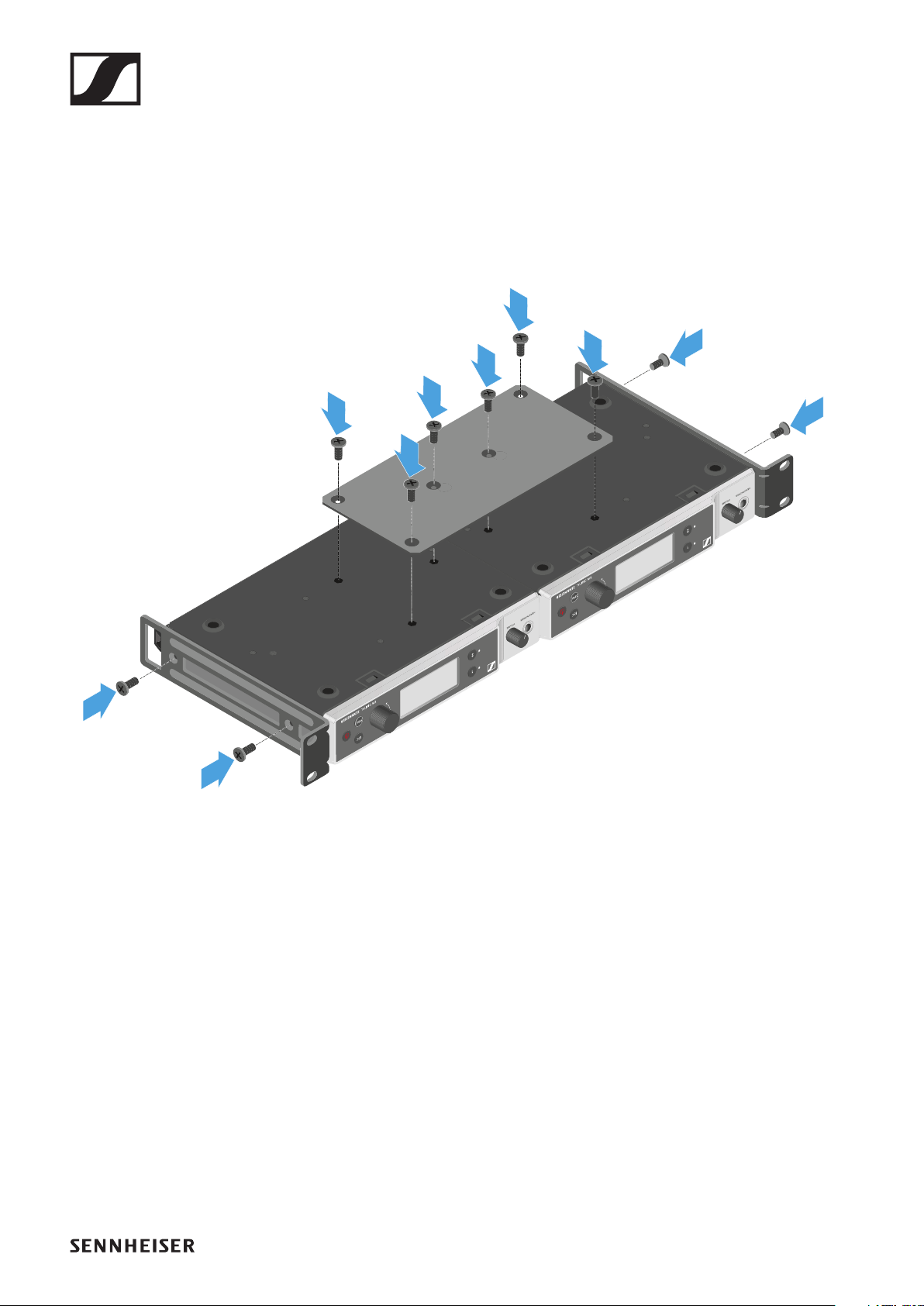
EW-DX EM 2 rack receiver
106
Mounting two receivers side by side in a rack
▷Place both receivers upside down and side by side on an
even surface.
▷Tighten the jointing plate as shown.
▷Attach the mounting brackets as shown.
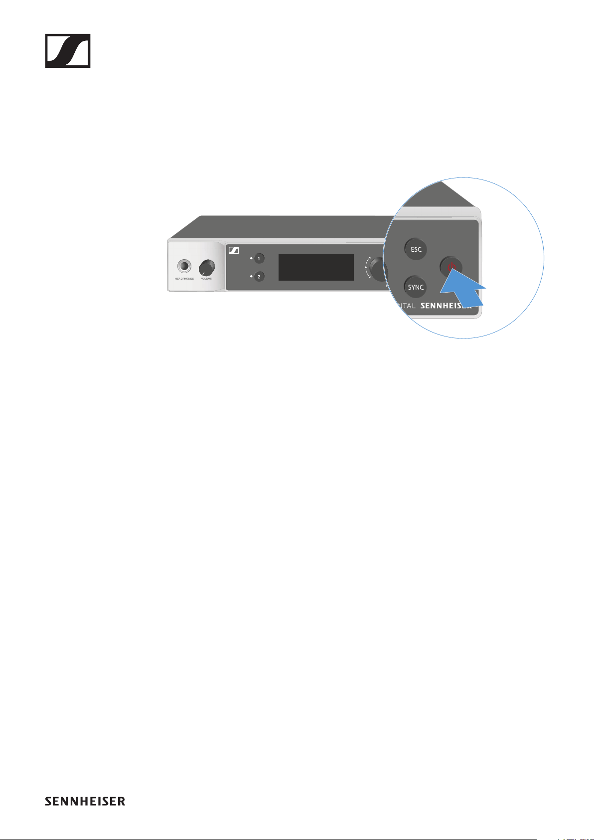
EW-DX EM 2 rack receiver
107
Switching the receiver on and off
To switch the receiver
on:
▷Short-press the ON/OFF button.
The receiver switches on.
To switch the receiver to
standby mode:
▷Hold down the ON/OFF button until the display switches
off.
To
switch the receiver off completely:
▷Disconnect the receiver from the power supply system by
unplugging the power supply unit from the wall socket or
disconnecting the PoE connection.
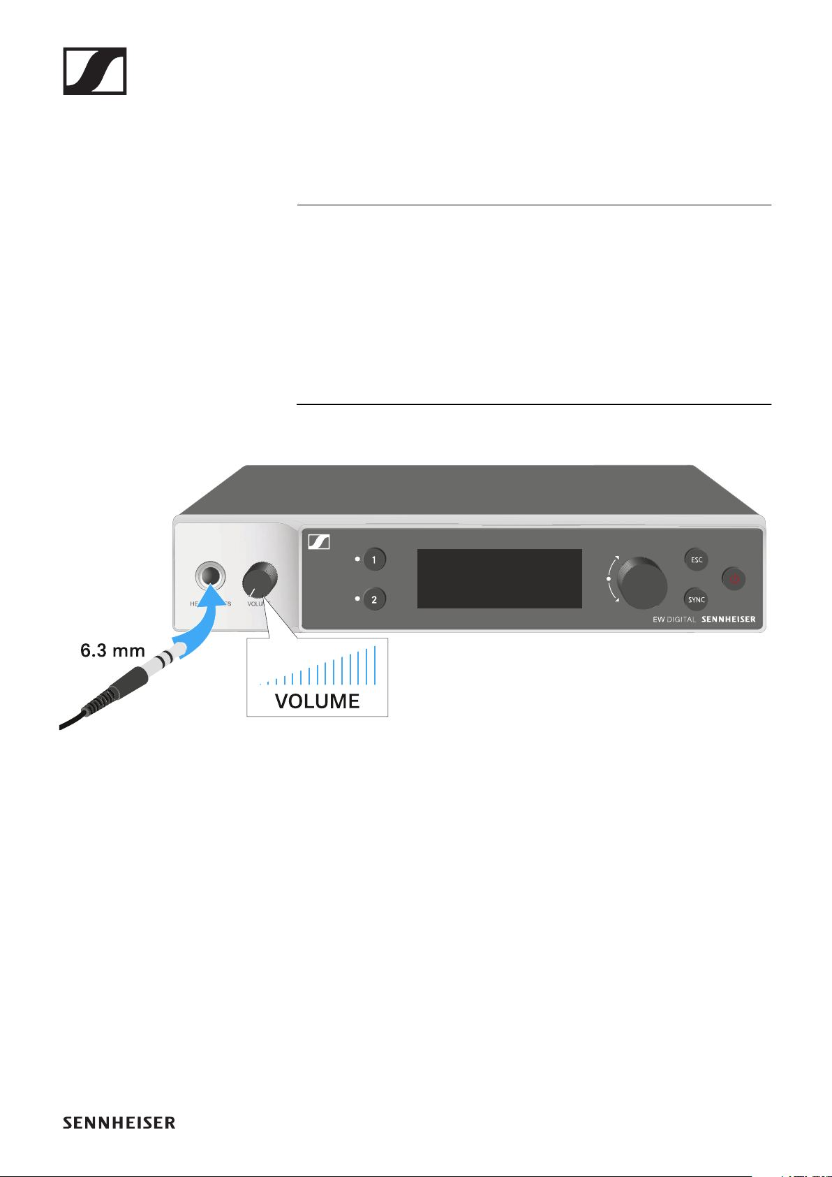
EW-DX EM 2 rack receiver
108
Using the headphone output
You can use the headphone output on the front of the receiver
(6.3 mm jack) to listen to the audio signals of the two channels.
CAUTION
Danger due to high volume levels
Volume levels that are too high may damage your hearing.
▷Turn down the volume of the headphone output before you
put on the headphone.
▷Connect the headphone to the headphone output.
▷Press the CH 1 or CH 2 button to listen to the audio signal
from channel 1 or channel 2.
The headphone icon on the display indicates which channel
is currently active on the headphone output.
By default, the signal from channel 1 is active on the head-
phone output.
▷You can control the volume by turning the volume knob
next to the headphone output.
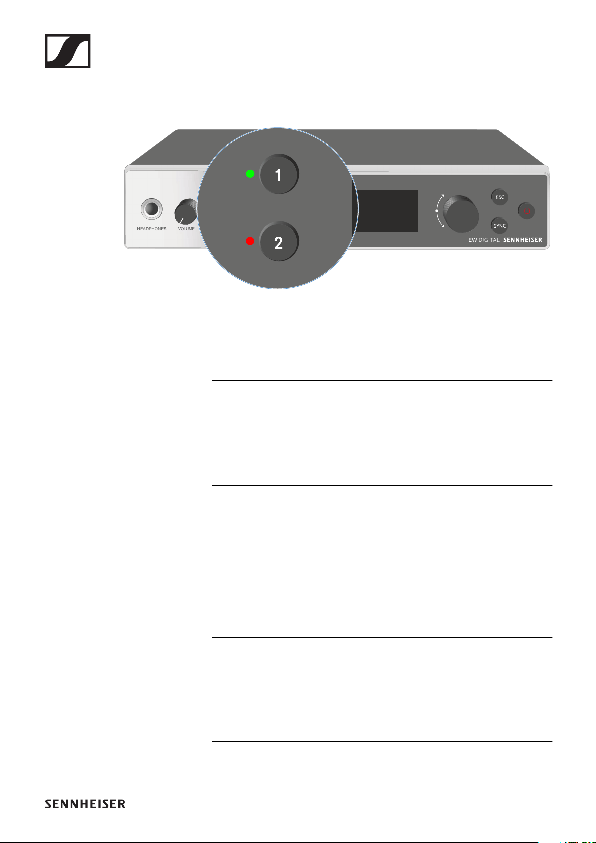
EW-DX EM 2 rack receiver
109
Meaning of the LEDs
The two LEDs on the front of the receiver indicate the follow-
ing information for channel 1 and channel 2.
The LED is green:
▷The link between the transmitter and receiving channel is
established.
▷The audio signal is active.
The LED is yellow:
▷The link between the transmitter and receiving channel is
established.
▷The audio signal is muted.
or
▷No microphone module is mounted on the handheld trans-
mitter.
The LED is flashing yellow:
▷The link between the transmitter and receiving channel is
established.
▷The audio signal is overdriven (clipping).
The LED is continuously red:
▷No link between the transmitter and receiving channel.
EW-DX EM 2 rack receiver
110
The LED is flashing red:
▷The link between the transmitter and receiving channel is
established.
▷The battery/rechargeable battery in the paired transmitter
is low.
The LED is flashing blue:
▷The Bluetooth Low Energy link is being established be-
tween the receiver and a smartphone or tablet with the
EW-D Smart Assist app.
or
▷The receiving channel is being synchronized with a trans-
mitter.
The LED is continuously blue:
▷The firmware is being updated.
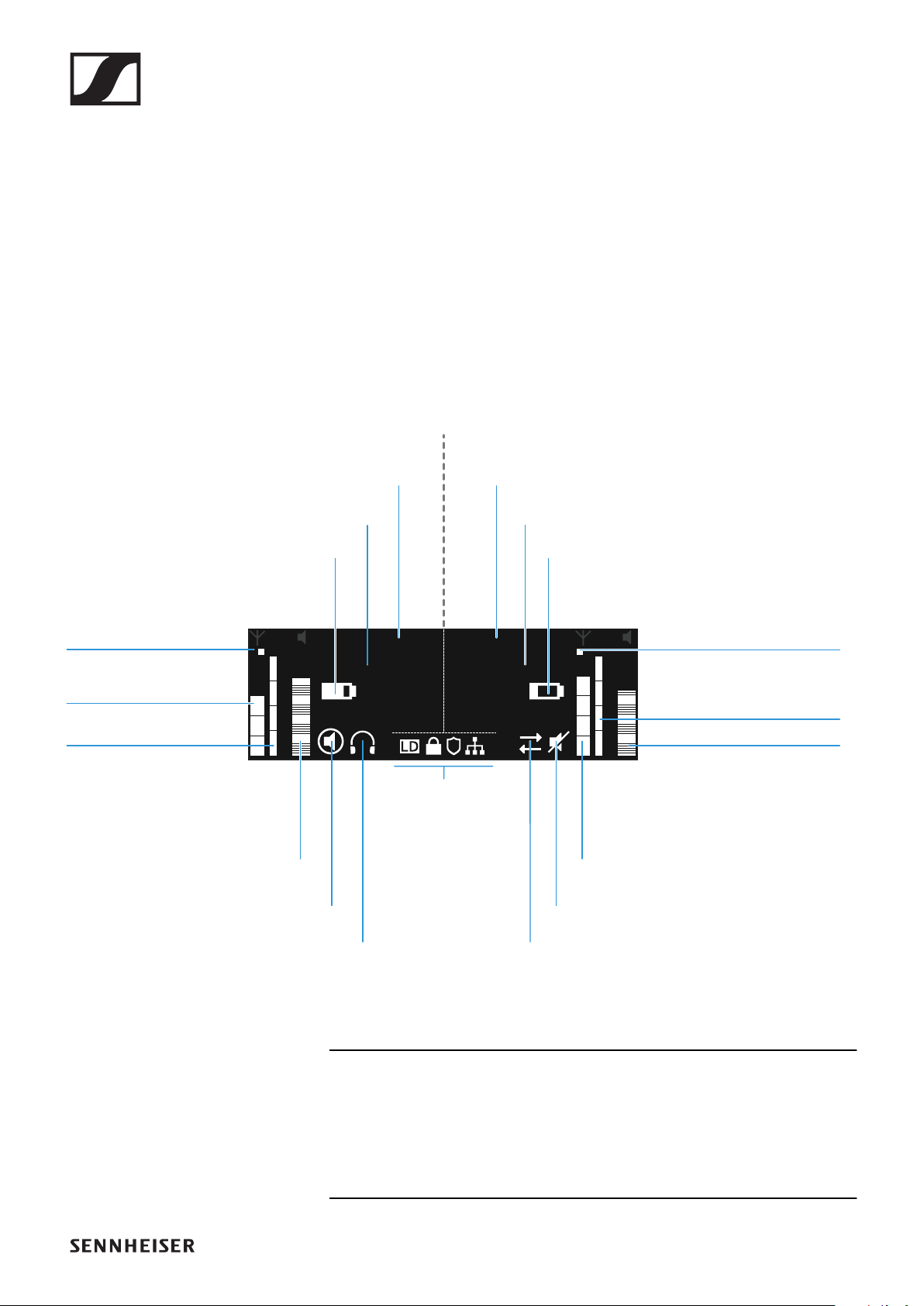
EW-DX EM 2 rack receiver
111
Displays on the receiver’s display panel
Status information such as frequency, reception quality, bat-
tery status and audio level is shown on the display.
The display also shows the operating menu, which you can use
to configure all of the settings (see "Buttons for navigating the
menu").
Home screen
The home screen is the default view on the display. The follow-
ing information for both receiving channels is displayed here.
Further information
Antenna switching diversity:
Indicates which of the two antennas is currently active (left or
right).
EW-DX 1
QQ
510.100
9:21
521.100
EW-DX 2
Transmitter
audio level
Transmitter
audio level
Transmitter
battery
Link quality
Radio frequency
level
Frequency
Link name
Transmitter
battery
Frequency
Link name
Channel 1 Channel 2
Mute mode
Headphones
Mute mode
Sync state
System
icons
Antenna
switching
diversity
Link quality
Radio frequency level
Antenna
switching
diversity

EW-DX EM 2 rack receiver
112
Radio frequency level:
Displays the RF signal strength for the respective channel.
Link quality:
Displays the transmission quality for the respective channel.
On the one hand, the transmission quality depends on the
f i el d str engt h ( RF l evel i ndi cat or on t he di spl ay). Ho wever,
on the other hand, it also depends on external sources of
interference that cannot be identif i ed on t he RF l evel i ndi-
cator (for example, they may be on the same frequency or
a very close neighboring frequency or may not affect the
f i el d str engt h).
As a basic principle, a value signif
i cantl y hi gher t han 50 %
should be ach
ieved for a secure transmission.
Link name:
You can assign a name to the radio link in the receiver menu
(see "Ch 1 / Ch 2 -> Name menu item").
Frequency:
You can set the frequency of the radio link manually or using
the Auto-Setup function.
•See "Ch 1 / Ch 2 -> Frequency menu item"
•See "Ch 1 / Ch 2 -> Scan / Auto Setup menu item"
Transmitter audio level:
Displays the audio input level for the respective channel (see
"Ch 1 / Ch 2 -> Gain menu item").
This level is separate from the audio level that is output from
the receiver (see "Ch 1 / Ch 2 -> AF Out menu item").
Transmitter battery:
Indicates the charging status of the transmitter’s BA 70 re-
chargeable battery or batteries.
When using the BA 70 rechargeable battery, the remaining
runtime is also displayed in hours and minutes.
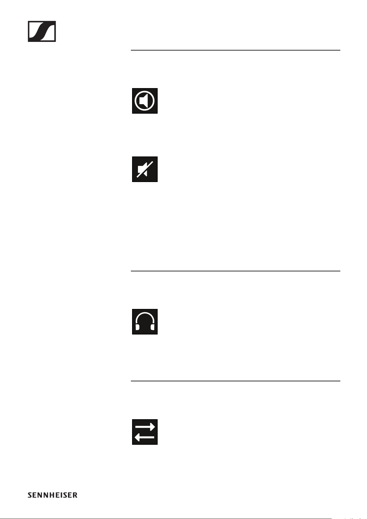
EW-DX EM 2 rack receiver
113
Mute mode:
The mute switch is deactivated on the received transmitter.
The mute switch on the received transmitter is set to AF Mute
and the audio signal is muted.
▷EW-DX SKM-S: "Configuring mute mode and muting the
handheld transmitter (EW-DX SKM-S only)"
▷EW-DX SK: "Configuring mute mode and muting the
bodypack transmitter"
Headphones:
The headphones icon indicates which channel is currently ac-
tive on the headphone output (see "Using the headphone out-
put").
Sync state
This icon indicates that different values are set for the receiv-
ing channel of the receiver and the transmitter. These values
can be synchronized (see "Connecting to the EW-DX EM 2 re-
ceiver / synchronizing the EW-DX EM 2").
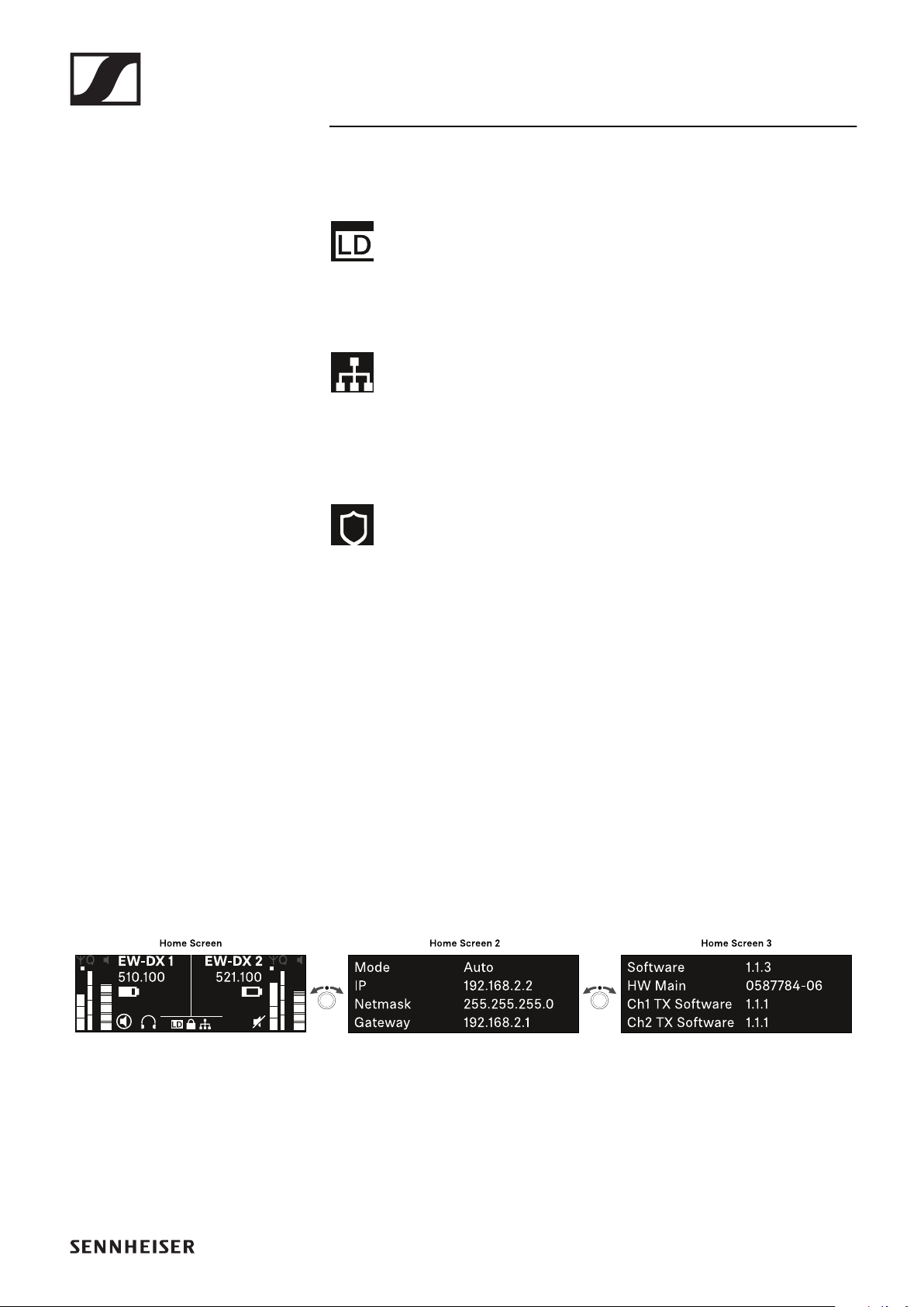
EW-DX EM 2 rack receiver
114
System icons:
The LD icon is displayed when Link Density mode is activated.
See "System -> Link Density menu item".
The network icon appears when a network connection is suc-
cessfully established. See "Connecting receivers in a net-
work".
The shield icon is displayed when AES 256 encryption is en-
abled. See "System -> Encryption menu item".
Home screens 2 and 3
▷Turn the jog dial on the home screen to the right.
The second home screen appears with network information
for the device.
▷Turn the jog dial to the right again.
The third home screen appears with information about the
software and hardware.
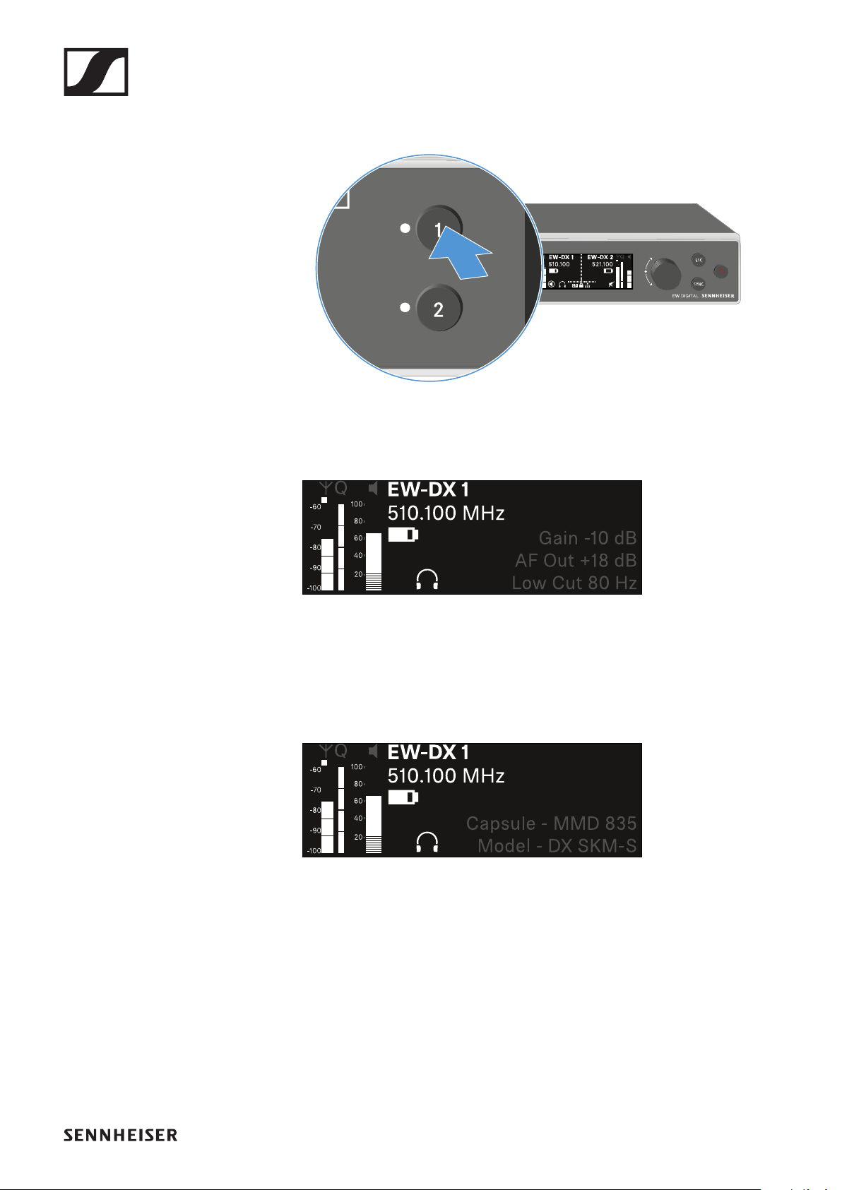
EW-DX EM 2 rack receiver
115
Channel 1
▷On the receiver’s home screen, press the CH 1 button.
The home screen for channel 1 appears.
In addition to the status information displayed on the home
screen, information about the channel’s audio settings is
also displayed.
▷Turn the jog dial to the right to view more information
about the received transmitter.
▷Turn the jog dial further to the right to mute or unmute the
channel’s audio signal.
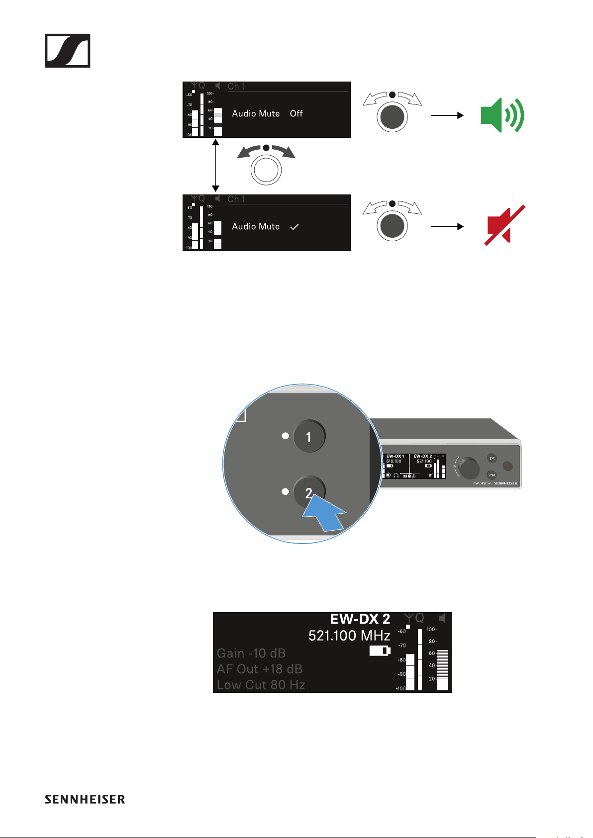
EW-DX EM 2 rack receiver
116
▷Press the jog dial to confirm your selection.
Channel 2
▷On the receiver’s home screen, press the CH 2 button.
The home screen for channel 2 appears.
You can view and configure the same information as for
channel 1.
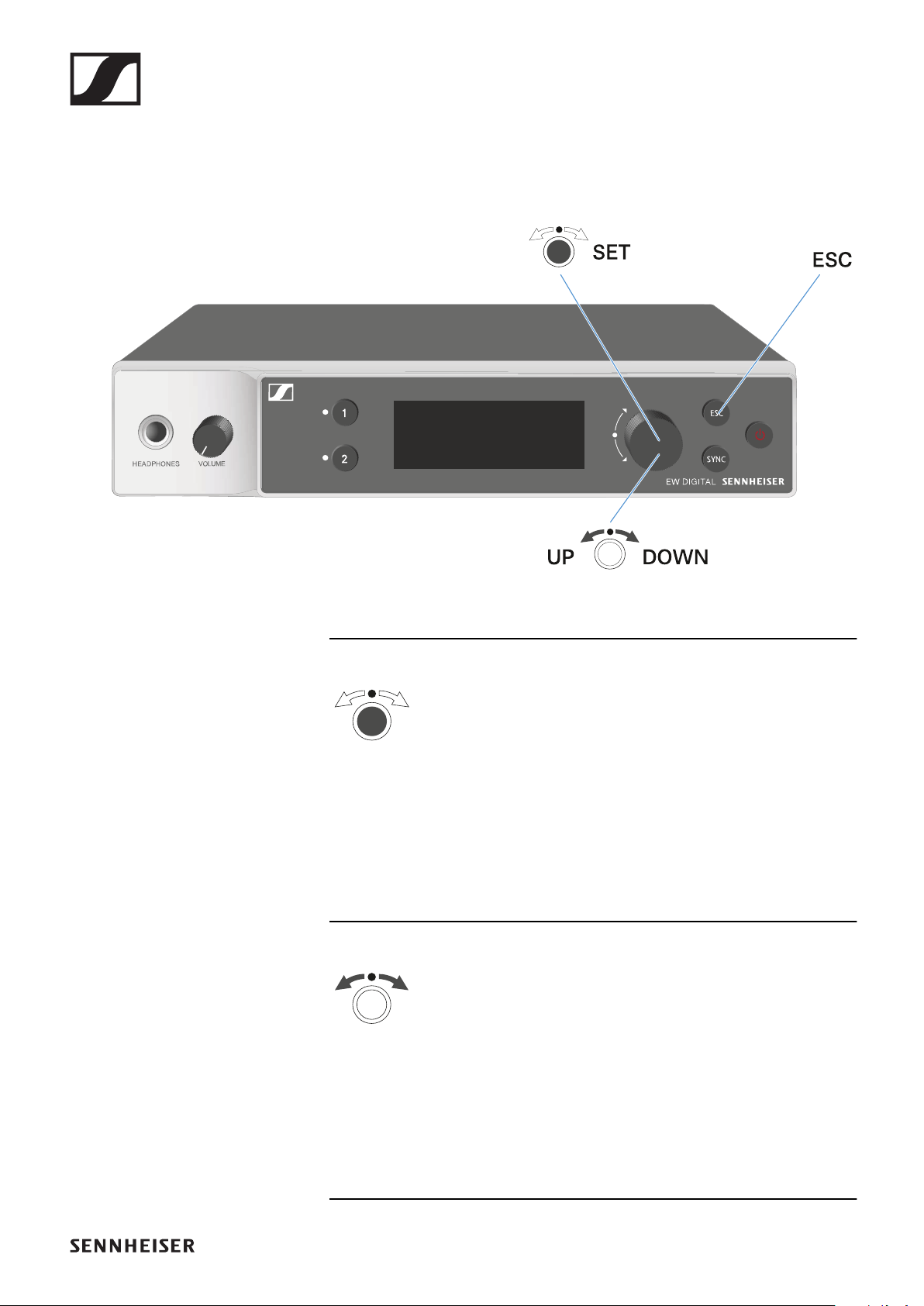
EW-DX EM 2 rack receiver
117
Buttons for navigating the menu
Use the following buttons to navigate through the receiver’s
operating menu.
►
Press the jog dial
•Jumps from the home screen to the operating menu
•Calls up a menu item
•Changes to a submenu
•Saves settings
►
Turn the jog dial
•Selects a standard display (see "Displays on the receiver’s
display panel")
•Changes to the previous or next menu item
•Changes the setting of a menu item
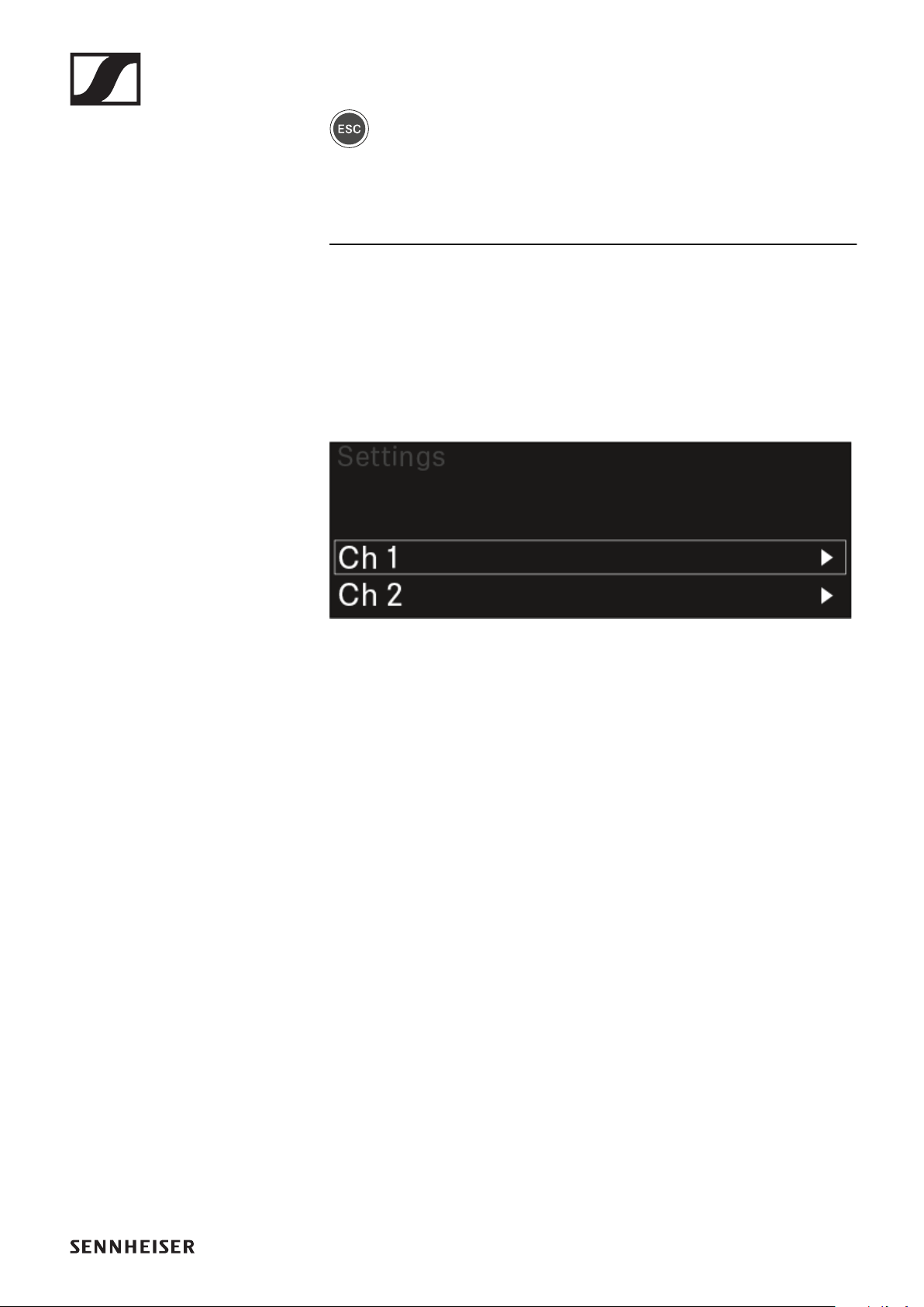
EW-DX EM 2 rack receiver
118
►
Press the ESC button
•Cancels the entry and returns to the previous display
Opening the menu and navigating the menu
items
To open the menu:
▷Press the jog dial when you are on the home screen.
▷Turn the jog dial to navigate to your desired menu item.
▷Press the jog dial to open the selected menu item.
To exit the menu:
▷Press the ESC button to exit the menu and return to the
home screen.
Changes that were not previously saved by pressing the
jog dial will be lost.
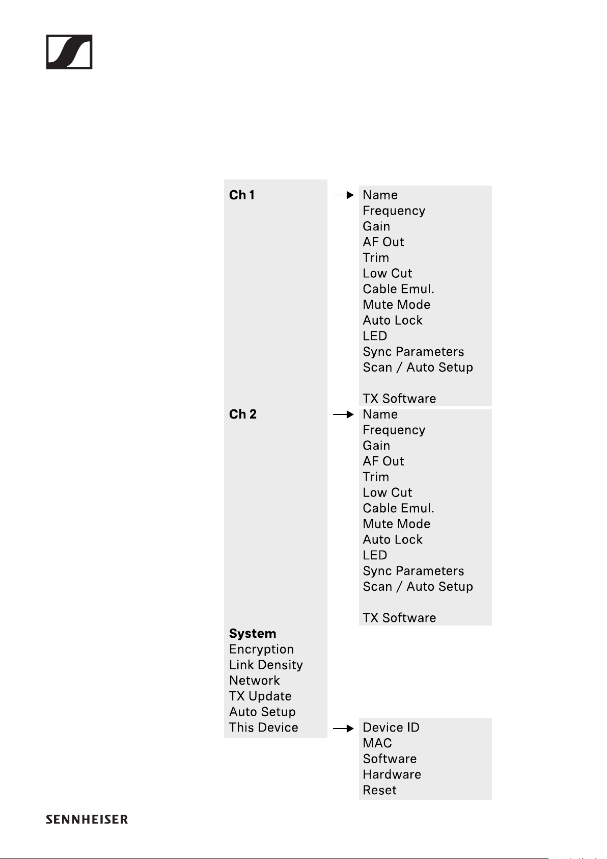
EW-DX EM 2 rack receiver
119
Menu structure
The figure shows the complete menu structure in an overview.
Version: firmware 1.1.3
EW-DX EM 2 rack receiver
120
Setting options in the menu
In the receiver menu, you can configure the following settings.
Changing the name of the radio link
▷"Ch 1 / Ch 2 -> Name menu item"
Adjusting frequencies
▷"Ch 1 / Ch 2 -> Frequency menu item"
Adjusting the gain of the wireless link
▷"Ch 1 / Ch 2 -> Gain menu item"
Setting the output level of the audio signal
▷"Ch 1 / Ch 2 -> AF Out menu item"
Adjusting the trim of the connected transmitter
▷"Ch 1 / Ch 2 -> Trim menu item"
Adjusting the low-cut filter
▷"Ch 1 / Ch 2 -> Low Cut menu item"
Configuring cable emulation for the bodypack transmitter
▷"Ch 1 / Ch 2 -> Cable Emul. menu item"
Setting the function of the transmitter’s mute switch
▷"Ch 1 / Ch 2 -> Mute Mode menu item"
EW-DX EM 2 rack receiver
121
Enabling the transmitter’s automatic lock-off function
▷"Ch 1 / Ch 2 -> Auto Lock menu item"
Configuring the behavior of the transmitter’s LEDs
▷"Ch 1 / Ch 2 -> LED menu item"
Activating/deactivating the parameters to be synchro-
nized on the transmitters
▷"Ch 1 / Ch 2 -> Sync Parameters menu item"
Performing a frequency scan and automatic frequency set-
up
▷"Ch 1 / Ch 2 -> Scan / Auto Setup menu item"
Viewing the software version of the connected transmit-
ters
▷"Ch 1 / Ch 2 -> TX Software menu item"
Configuring different system settings
•Enabling AES 256 encryption
•Setting transmission mode
•Configuring network settings
•Updating the firmware for the transmitters
•Activating the Auto Setup function
•Changing device names
▷"System menu item"
You can find an overview of the entire menu structure under
"Menu structure".
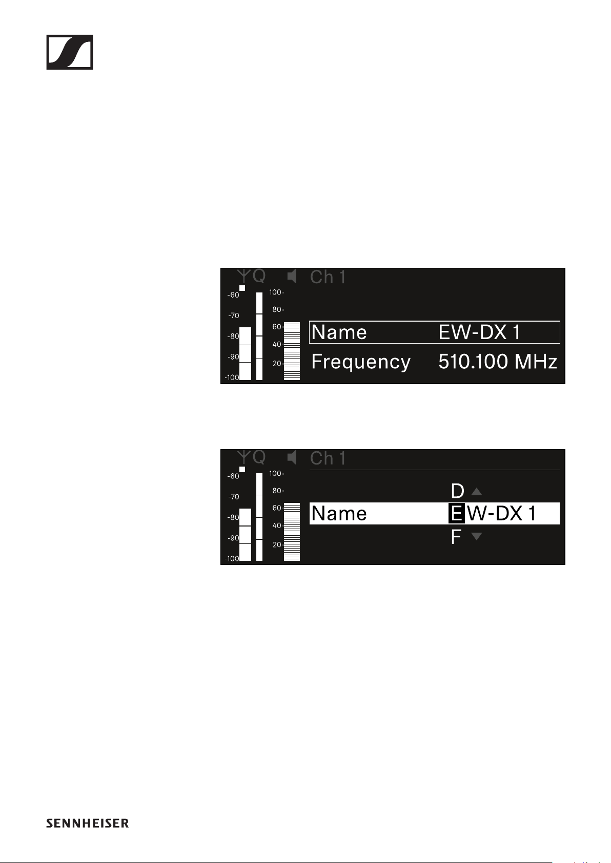
EW-DX EM 2 rack receiver
122
Ch 1 / Ch 2 -> Name menu item
In the Name menu item, you can define the name of the link for
the channel in question.
This name is the name of the radio link between the transmit-
ter and receiving channel. You can set the name of the receiver
as it will appear in a network from the This Device menu in the
system menu. See "System -> This Device menu item".
To open the Name menu item:
▷In the menu, navigate to the Name menu item for the de-
sired channel.
▷Press the jog dial to open the menu.
The following view is displayed:
To enter the desired link name:
▷Turn the jog dial to select the desired character.
▷Press the jog dial to go to the next position.
▷At the last position, press the jog dial to save the selected
name.
or
▷Press the ESC button to cancel the entry without saving the
setting.
For the chosen link name to appear on the display of the re-
ceived transmitter, you must synchronize the channel ("Con-
necting to the EW-DX EM 2 receiver / synchronizing the EW-
DX EM 2").
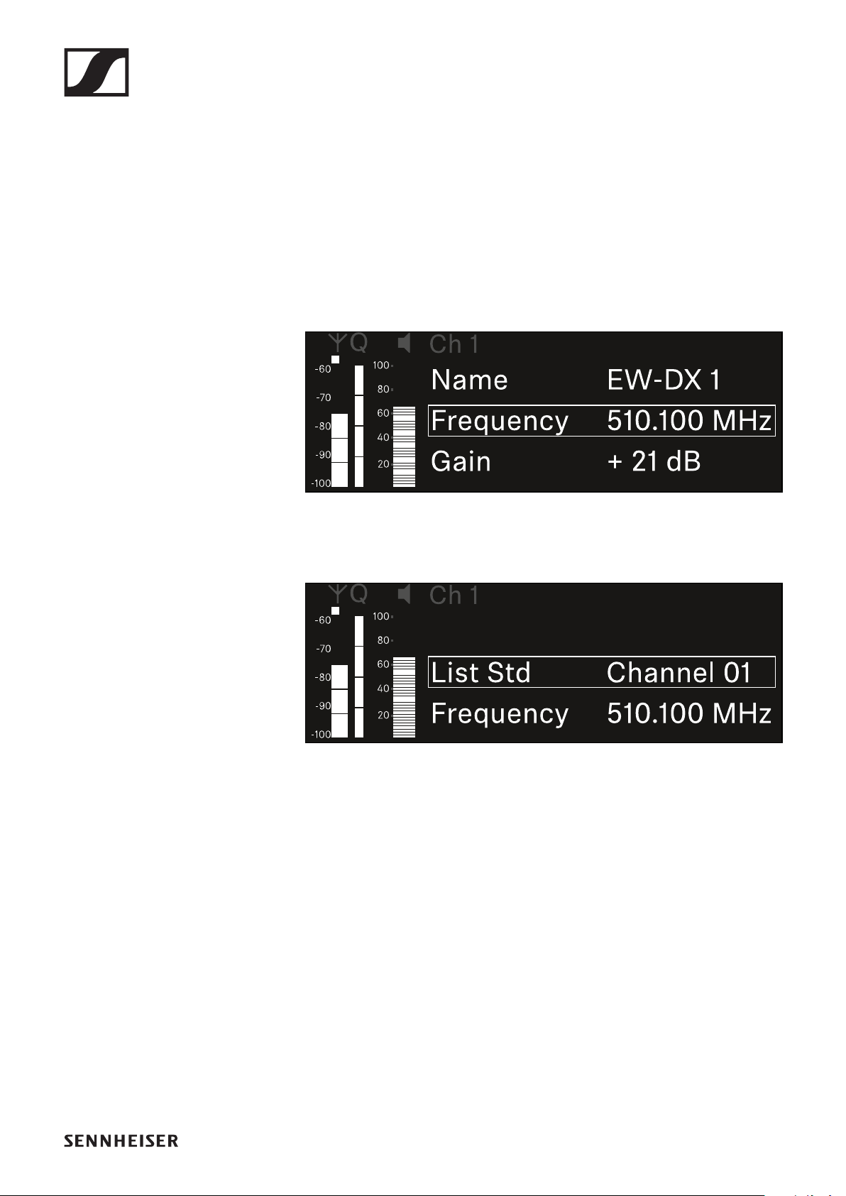
EW-DX EM 2 rack receiver
123
Ch 1 / Ch 2 -> Frequency menu item
In the Frequency menu item, you can adjust the frequency for
the channel in question.
You can select a frequency from the predefined list or set the
frequency manually.
To open the Frequency menu item:
▷In the menu, navigate to the Frequency menu item for the
desired channel.
▷Press the jog dial to open the menu.
The following view is displayed:
▷Rotate the jog dial to select between the List and Frequen-
cy subitems.
The List subitem allows you to select a frequency from the
predefined list.
The Frequency subitem lets you set the desired frequency
manually.
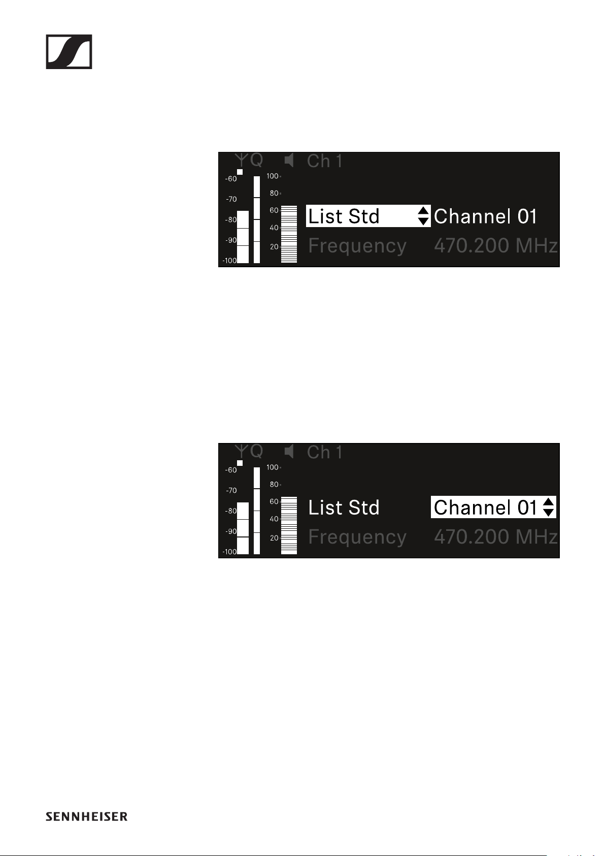
EW-DX EM 2 rack receiver
124
Selecting a frequency from a predefined list
To select a frequency from a predefined list:
▷Open the List subitem.
▷Rotate the jog dial to choose between the predefined list
(List Std) and the user-defined list (List Usr).
You can create a custom list using the Wireless Systems
Manager (WSM) software and upload it to the receiver. For
more information on the WSM software, see:
www.sennheiser.com/wsm
▷Press the jog dial to confirm your selection.
▷Rotate the jog dial to select the desired channel from the
list.
The frequency assigned to the channel is displayed.
▷Press the jog dial to save the selected channel.
or
▷Press the ESC button to cancel the entry without saving the
setting.
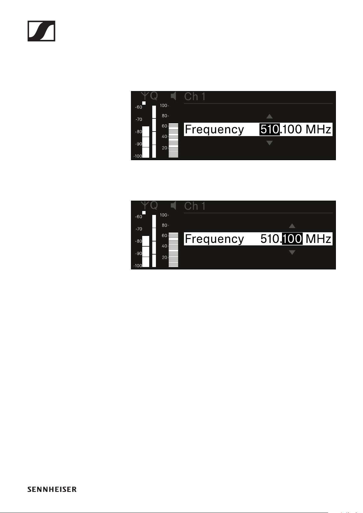
EW-DX EM 2 rack receiver
125
Setting the frequency manually
To set the frequency manually:
▷Open the Frequency subitem.
▷Turn the jog dial to set the MHz range for the frequency.
▷Press the jog dial to confirm your selection.
▷Turn the jog dial to set the kHz range for the frequency.
▷Press the jog dial to save your selected frequency.
or
▷Press the ESC button to cancel the entry without saving the
setting.
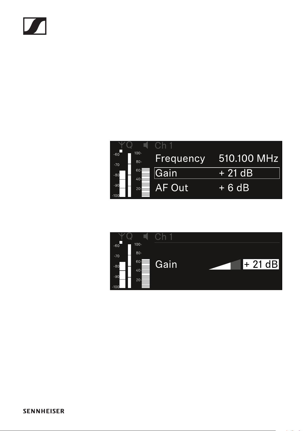
EW-DX EM 2 rack receiver
126
Ch 1 / Ch 2 -> Gain menu item
Under the Gain menu item, you can set the audio level of the
audio signal coming from the received transmitter (e.g. vocals
or speech via EW-DX SKM or guitar via EW-DX SK).
•Setting range: 3 dB to +42 dB in increments of 3 dB
To open the Gain menu item:
▷In the menu, navigate to the Gain menu item for the desired
channel.
▷Press the jog dial to open the menu.
The following view is displayed:
▷Turn the jog dial to set the desired value.
▷Press the jog dial to save your setting.
or
▷Press the ESC button to cancel the entry without saving the
setting.
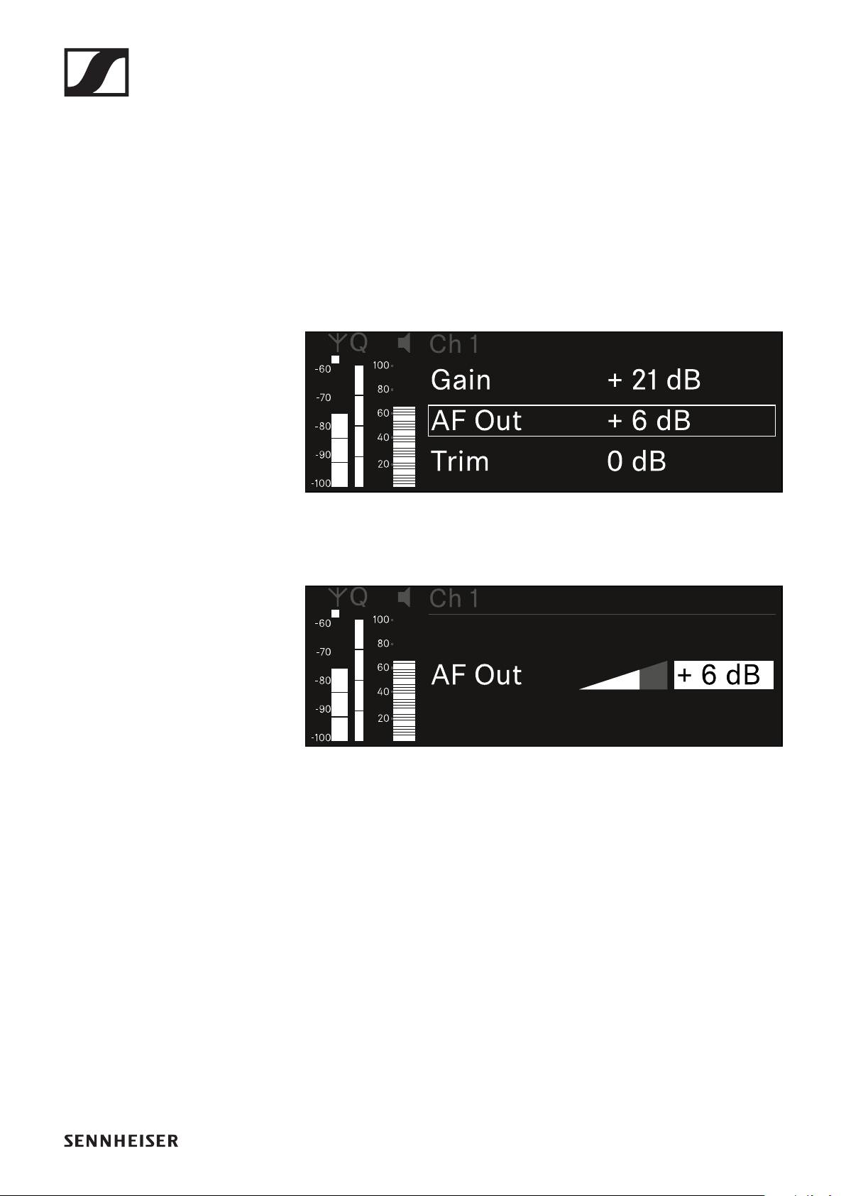
EW-DX EM 2 rack receiver
127
Ch 1 / Ch 2 -> AF Out menu item
In the AF Out menu item, you can set the audio level that is
output via the audio outputs of the particular receiving chan-
nel.
To open the AF Out menu item:
▷In the menu, navigate to the AF Out menu item for the de-
sired channel.
▷Press the jog dial to open the menu.
The following view is displayed:
▷Turn the jog dial to set the desired value.
▷Press the jog dial to save your setting.
or
▷Press the ESC button to cancel the entry without saving the
setting.
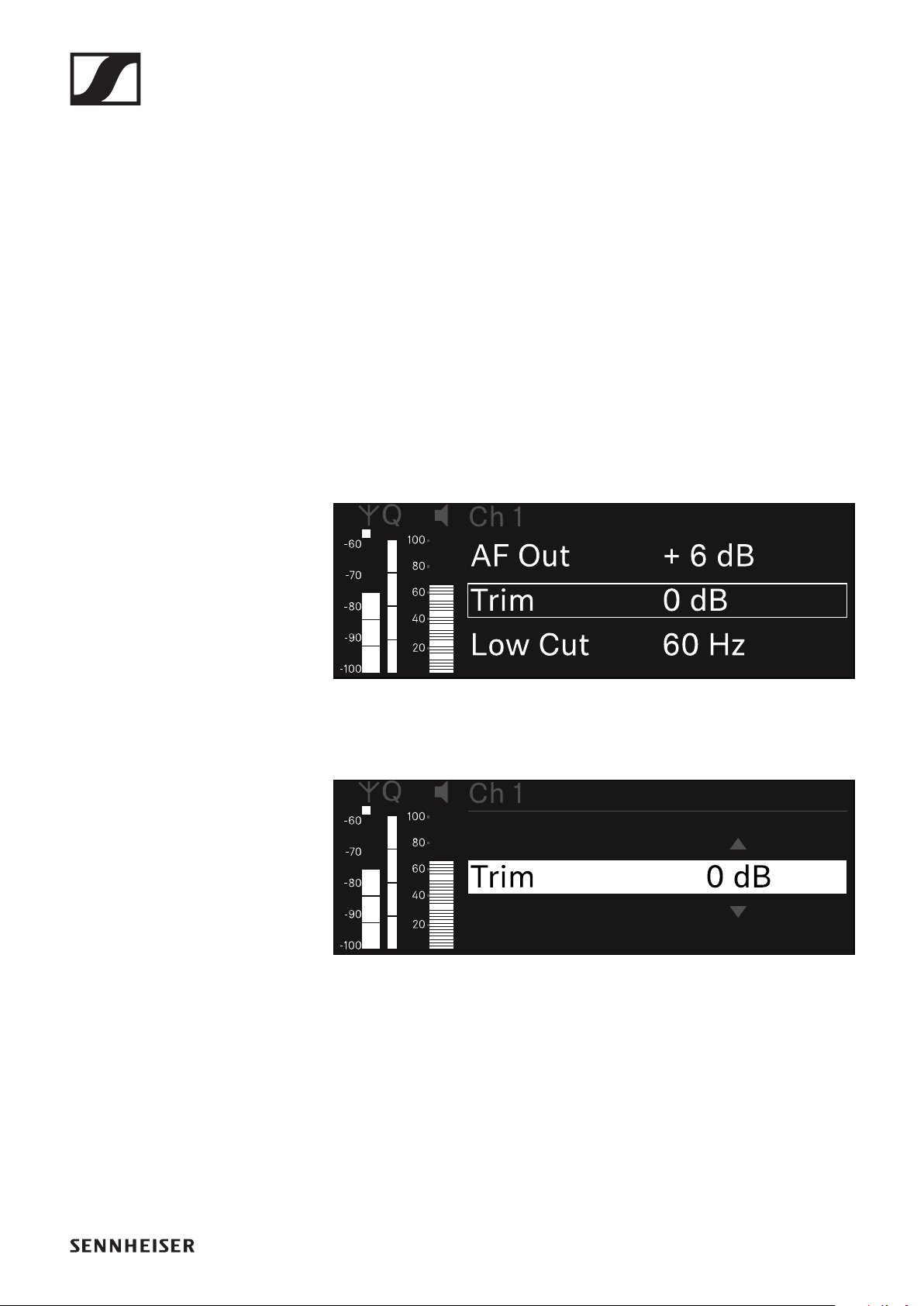
EW-DX EM 2 rack receiver
128
Ch 1 / Ch 2 -> Trim menu item
In the Trim menu item, you can adjust the audio level of the re-
ceived transmitter to input signals of different volumes.
For example, if you are using multiple transmitters in alterna-
tion for a single receiving channel, you can adjust the trans-
mitters to the different input signals using the trim setting.
You do not need to change the channel’s gain setting.
•Setting range: -12 dB to +6 dB in increments of 1 dB
To open the Trim menu item:
▷In the menu, navigate to the Trim menu item for the desired
channel.
▷Press the jog dial to open the menu.
The following view is displayed:
▷Turn the jog dial to set the desired value.
▷Press the jog dial to save your setting.
or
▷Press the ESC button to cancel the entry without saving the
setting.
For the set value to be applied to the received transmitter, you
must synchronize the channel ("Connecting to the EW-
DX EM 2 receiver / synchronizing the EW-DX EM 2").
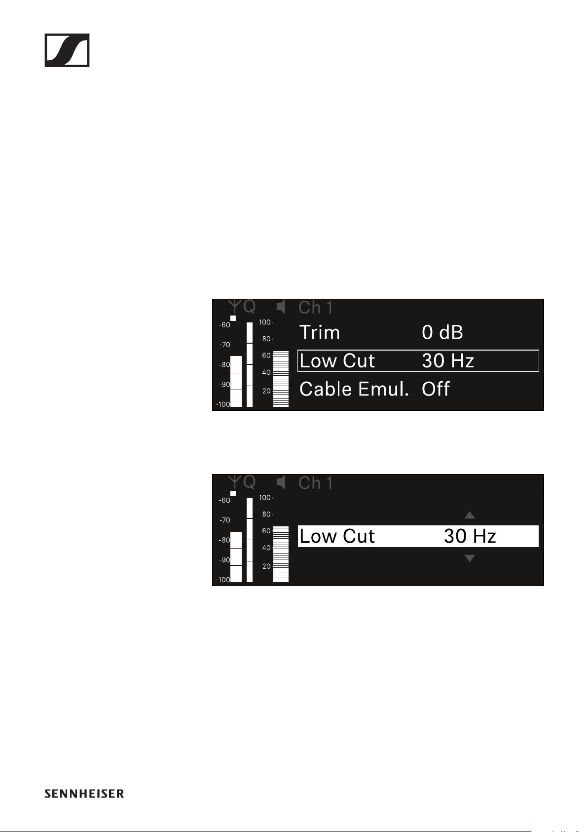
EW-DX EM 2 rack receiver
129
Ch 1 / Ch 2 -> Low Cut menu item
In the Low Cut menu item, you can set the value of the low cut
filter for the respective channel.
•Setting range:
•for EW-DX SK | EW-DX SK 3-PIN: Off, 30 Hz, 60 Hz, 80 Hz,
100 Hz, 120 Hz
•for EW-DX SKM | EW-DX SKM-S: 60 Hz, 80 Hz, 100 Hz,
120 Hz
To open the Low Cut menu item:
▷In the menu, navigate to the Low Cut menu item for the de-
sired channel.
▷Press the jog dial to open the menu.
The following view is displayed:
▷Turn the jog dial to set the desired value.
▷Press the jog dial to save your setting.
or
▷Press the ESC button to cancel the entry without saving the
setting.
For the set value to be applied to the received transmitter, you
must synchronize the channel ("Connecting to the EW-
DX EM 2 receiver / synchronizing the EW-DX EM 2").
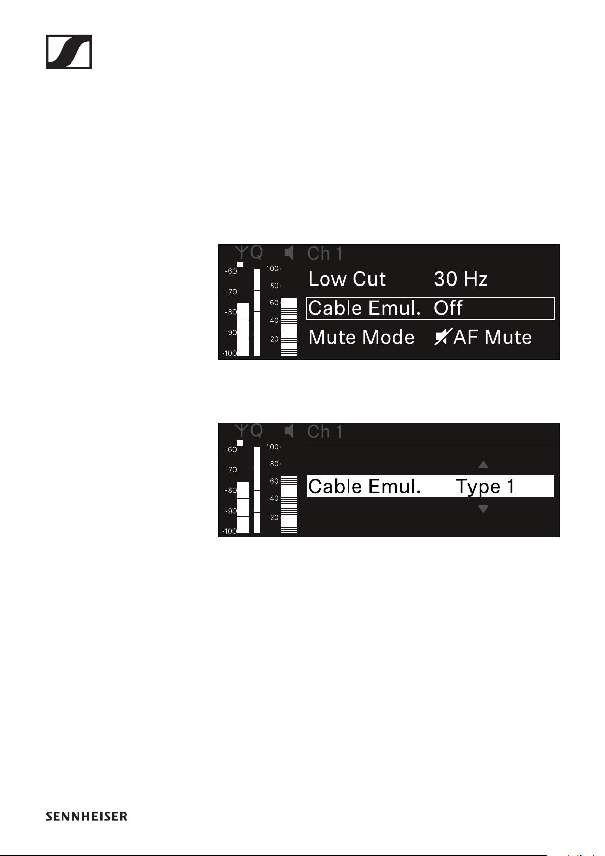
EW-DX EM 2 rack receiver
130
Ch 1 / Ch 2 -> Cable Emul. menu item
In the Cable Emul. menu item, you can emulate instrument ca-
ble lengths:
•Setting range: Off, Type 1, Type 2, Type 3
To open the Cable Emul. menu item:
▷In the menu, navigate to the Cable Emul. menu item for the
desired channel.
▷Press the jog dial to open the menu.
The following view is displayed:
▷Turn the jog dial to set the desired value.
▷Press the jog dial to save your setting.
or
▷Press the ESC button to cancel the entry without saving the
setting.
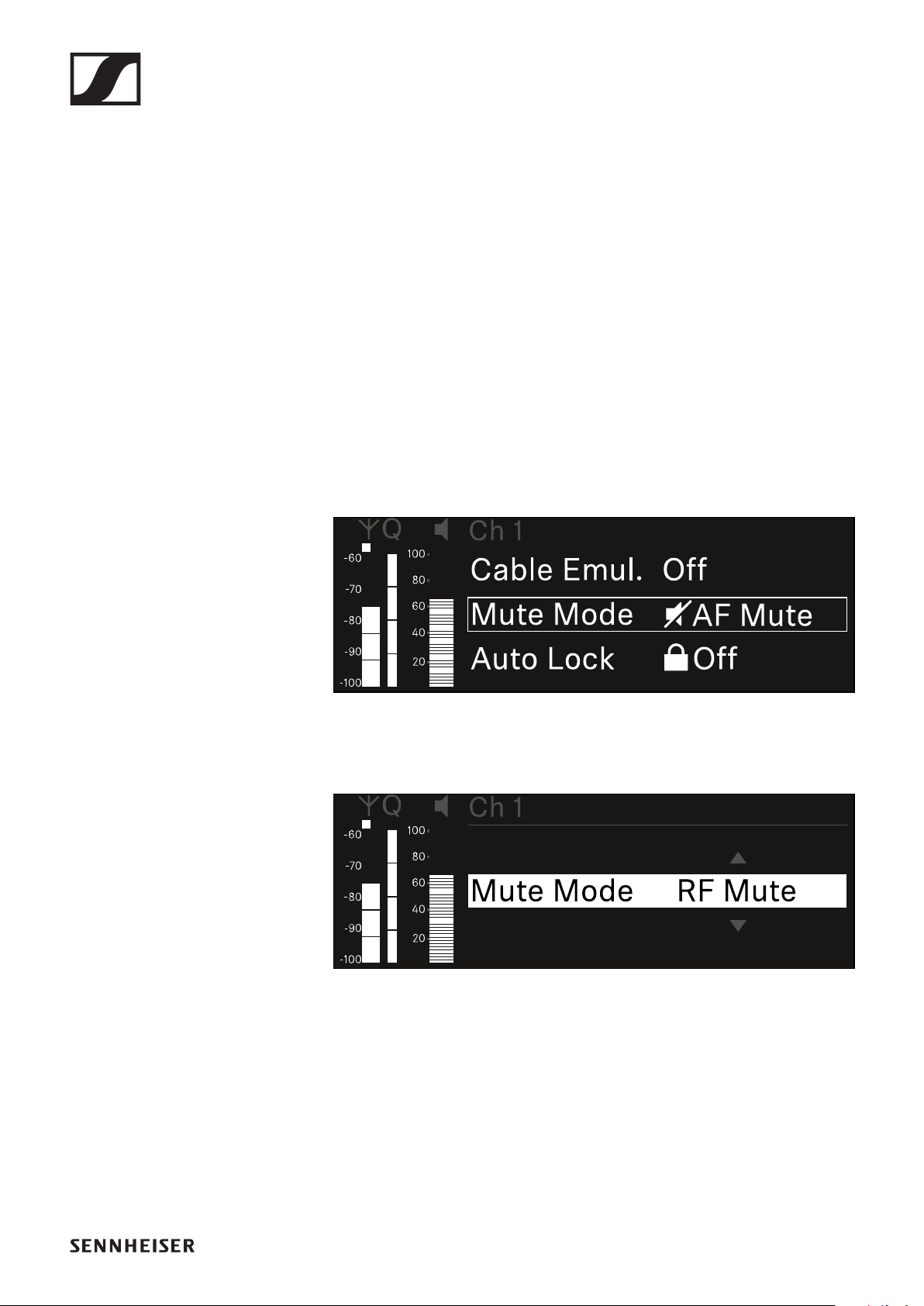
EW-DX EM 2 rack receiver
131
Ch 1 / Ch 2 -> Mute Mode menu item
In the Mute Mode menu item, you can set the function of the
mute switch on the connected transmitter (EW-DX SK, EW-DX
SK 3-PIN, EW-DX SKM-S).
•Setting range:
•Disabled: The mute switch has no function.
•RF Mute: The RF signal is deactivated when the mute
switch is on.
•AF Mute: The audio signal is muted when the mute switch
is on.
To open the Mute Mode menu item:
▷In the menu, navigate to the Mute Mode menu item for the
desired channel.
▷Press the jog dial to open the menu.
The following view is displayed:
▷Turn the jog dial to set the desired value.
▷Press the jog dial to save your setting.
or
▷Press the ESC button to cancel the entry without saving the
setting.
For the set value to be applied to the received transmitter, you
must synchronize the channel ("Connecting to the EW-
DX EM 2 receiver / synchronizing the EW-DX EM 2").
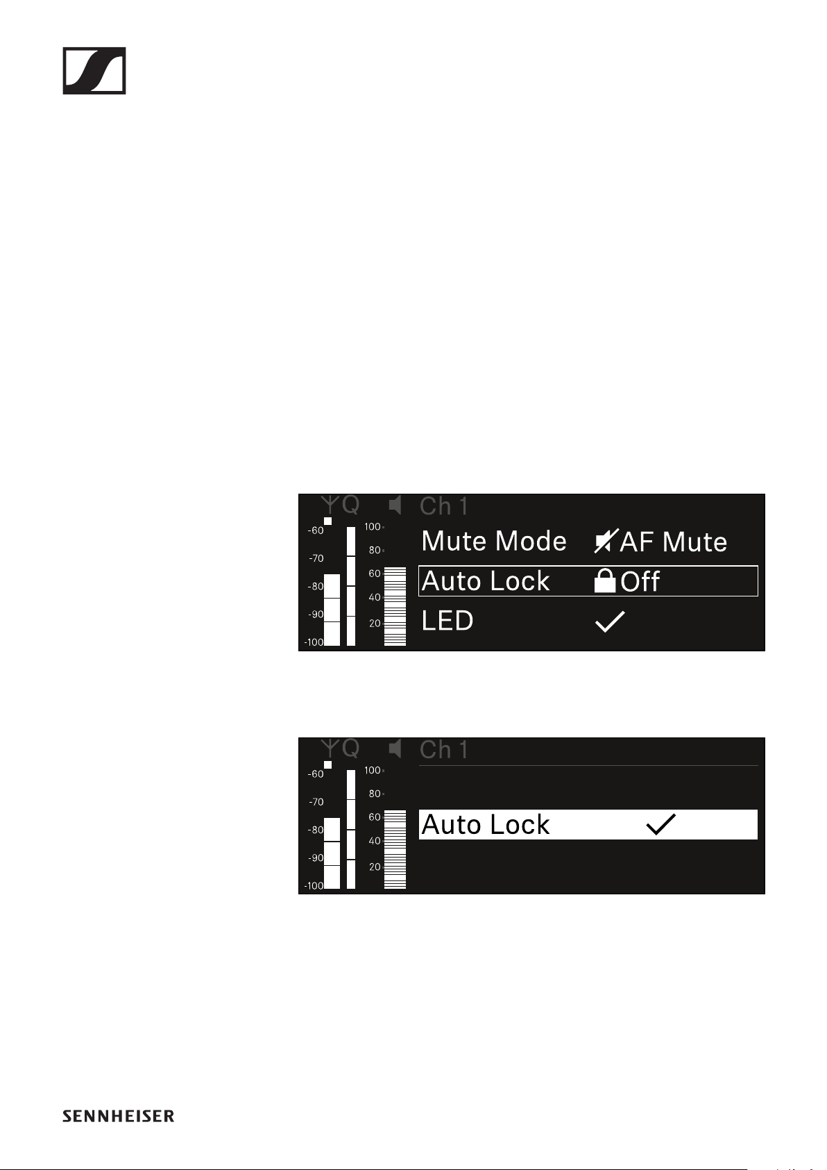
EW-DX EM 2 rack receiver
132
Ch 1 / Ch 2 -> Auto Lock menu item
In the Auto Lock menu item, you can activate or deactivate the
lock-off for the received transmitter.
The lock-off prevents the transmitter from being unintention-
ally switched off and also prevents any changes to the trans-
mitter’s menu.
If you want to change settings in the transmitter’s menu while
the lock-off is active, you have to temporarily disable the lock-
off:
▷EW-DX SKM: "Lock-off function"
▷EW-DX SK: "Lock-off function"
To open the Auto Lock menu item:
▷In the menu, navigate to the Auto Lock menu item for the
desired channel.
▷Press the jog dial to open the menu.
The following view is displayed:
▷Turn the jog dial to set the desired value.
▷Press the jog dial to save your setting.
or
▷Press the ESC button to cancel the entry without saving the
setting.
For the set value to be applied to the received transmitter, you
must synchronize the channel ("Connecting to the EW-
DX EM 2 receiver / synchronizing the EW-DX EM 2").
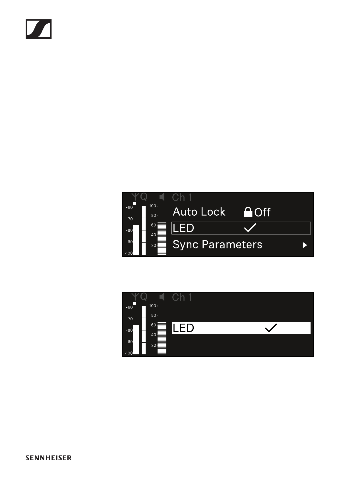
EW-DX EM 2 rack receiver
133
Ch 1 / Ch 2 -> LED menu item
The LED menu item allows you to set the behavior of the LINK
LED on the received transmitter.
•Setting range:
•ON: The LINK LED remains continuously lit.
•OFF: The LINK LED switches off while the lock-off func-
tion is active.
For this to occur, the automatic lock-off function must be en-
abled in the Auto Lock menu item (see "Ch 1 / Ch 2 -> Auto
Lock menu item").
To open the LED menu item:
▷In the menu, navigate to the LED menu item for the desired
channel.
▷Press the jog dial to open the menu.
The following view is displayed:
▷Turn the jog dial to set the desired value.
▷Press the jog dial to save your setting.
or
▷Press the ESC button to cancel the entry without saving the
setting.
For the set value to be applied to the received transmitter, you
must synchronize the channel ("Connecting to the EW-
DX EM 2 receiver / synchronizing the EW-DX EM 2").
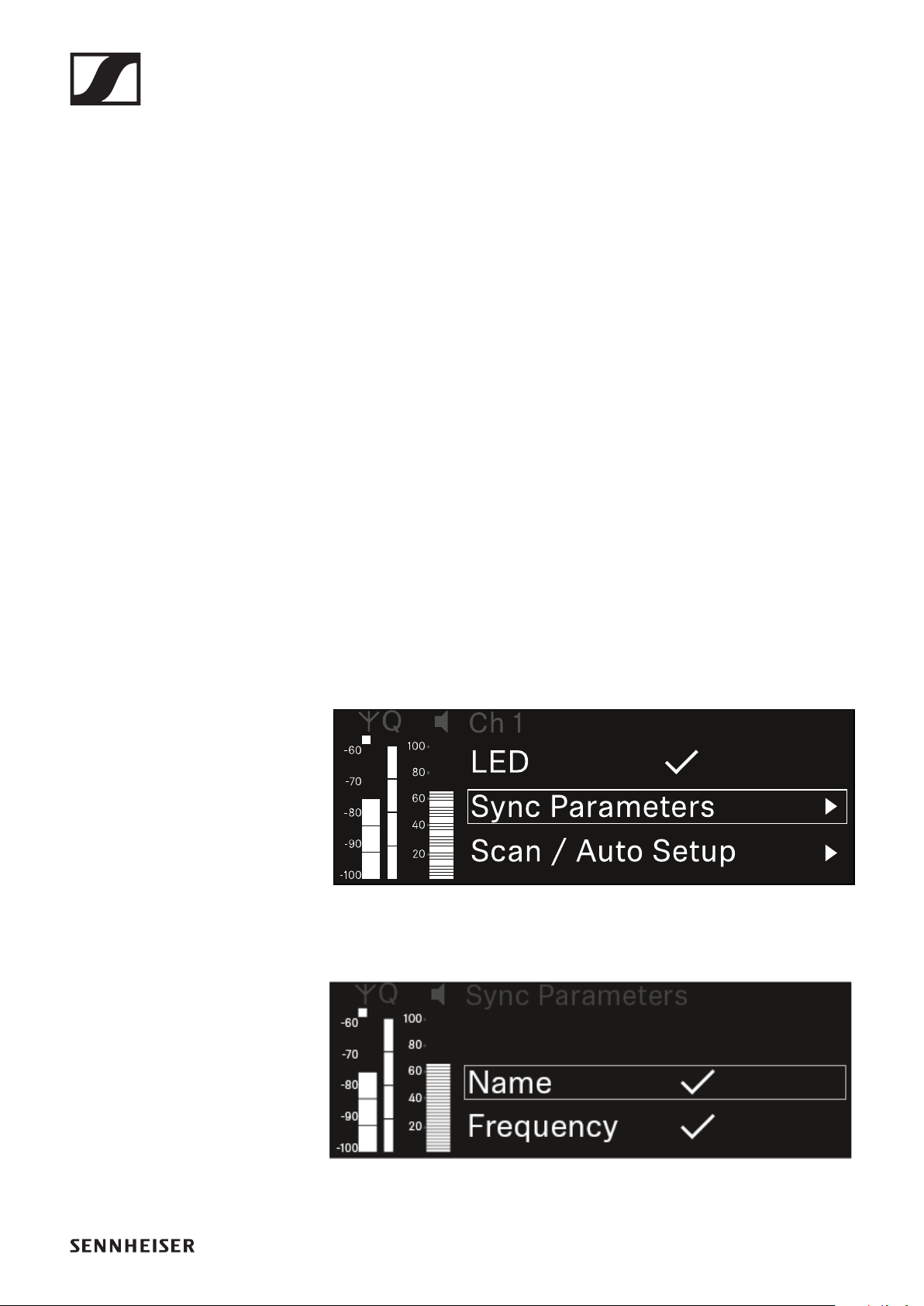
EW-DX EM 2 rack receiver
134
Ch 1 / Ch 2 -> Sync Parameters menu item
In the Sync Parameters menu item, you can choose which
settings for the transmitter you want to transfer from the re-
ceiver to the transmitter during the synchronization.
All of the settings can also be set separately in the menu on
the transmitter. During synchronization, the values set in the
transmitter are overwritten with the values set in the receiver.
The following parameters can be enabled or disabled for
transmission.
•Name
•Frequency
•Trim
•Low Cut
•Cable Emul.
•Mute Mode
•Auto Lock
•LED
To open the Sync Settings menu item:
▷In the menu, navigate to the Sync Settings menu item for
the desired channel.
▷Press the jog dial to open the menu.
The following view is displayed:
▷Turn the jog dial to choose between the options.
▷Press the jog dial to open your selected option.

EW-DX EM 2 rack receiver
135
▷For each option, select whether it will be synchronized or
not.
The value set for this function will be transferred during
synchronization.
The value set for this function will not be transferred during
synchronization.
▷Press the jog dial to save your setting.
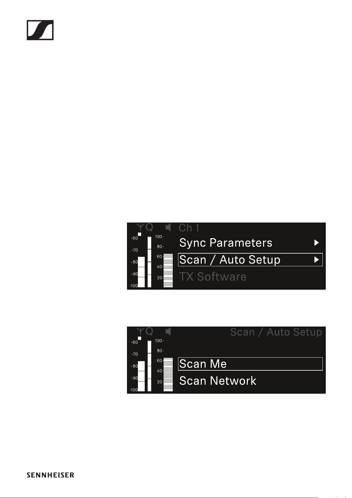
EW-DX EM 2 rack receiver
136
Ch 1 / Ch 2 -> Scan / Auto Setup menu item
The receiver lets you scan the frequency spectrum and display
all of the free frequencies in the selected frequency range. The
automatic frequency setup can be used to distribute the free
frequencies to all of the EW-DX EM 2 devices available in the
network automatically.
▷Switch off all transmitters before you perform the scan.
If transmitters are still switched on, they are detected as
unavailable frequencies and the frequencies that are actu-
ally available cannot then be used.
To perform the automatic frequency setup for all devices in
the network, the Auto Setup function must be enabled in the
receiver’s system menu: "System -> Auto Setup menu item".
To open the Scan / Auto Setup menu item:
▷In the menu, navigate to the Scan / Auto Setup menu item
for the desired channel.
▷Press the jog dial to open the menu.
The following view is displayed:
▷Turn the jog dial to choose between the Scan Me and Scan
Network options.
•Scan Me: The frequency scan and the frequency setup
are performed only for the selected receiving channel.
•Scan Network: The frequency scan and the frequency
setup are performed for both channels of the receiver as
well as for all other receivers available in the network.
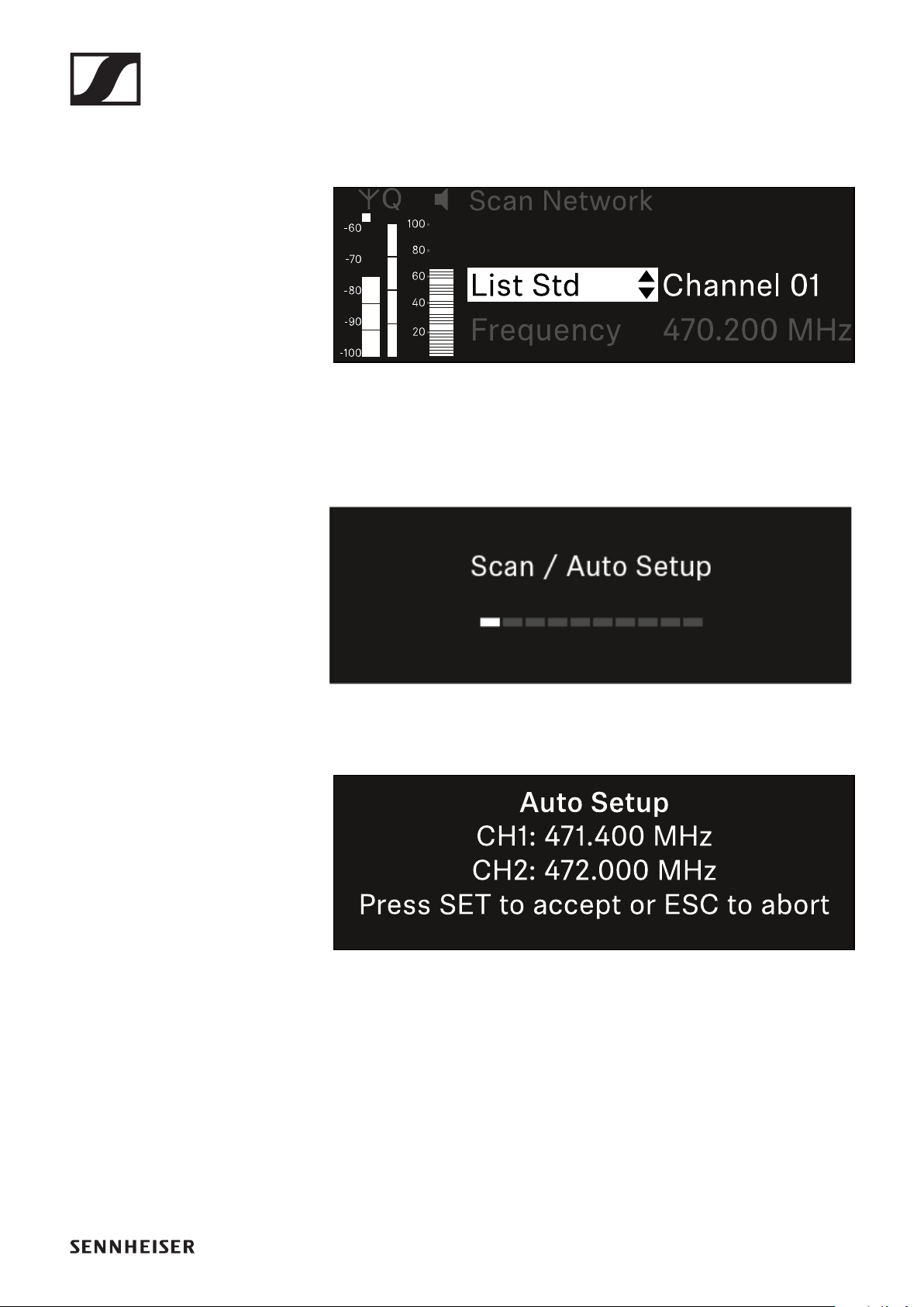
EW-DX EM 2 rack receiver
137
▷Press the jog dial to open your selected option.
▷Select a frequency from which to start the scan.
▷Press the jog dial to start the scan.
The spectrum is scanned for free frequencies above the se-
lected frequency.
After the scan free frequencies are displayed, which you
can then assign to the channels.
▷Press the jog dial to assign the free frequencies to the re-
ceiving channels.
or
▷Press the ESC key to cancel and not assign new frequen-
cies.
▷Next, synchronize the receiving channels with the corre-
sponding transmitters to establish the radio link at the new
selected frequencies ("Synchronizing the receiver and
transmitter").
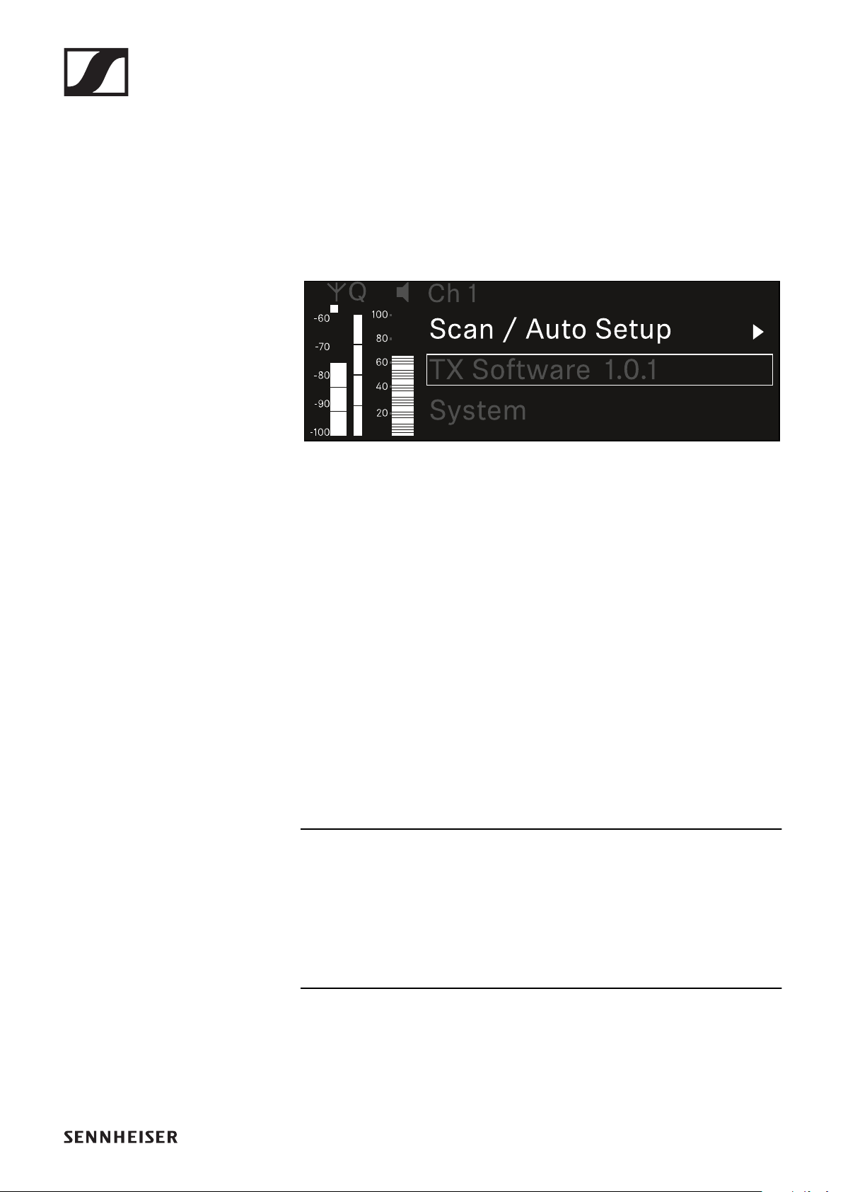
EW-DX EM 2 rack receiver
138
Ch 1 / Ch 2 -> TX Software menu item
The TX Software menu item displays the software version of
the received transmitter.
You cannot open this menu item to make settings.
▷In the menu, navigate to the TX Software menu item for the
desired channel.
The version number of the transmitter software is shown
on the display.
The transmitter must be switched on for this to be dis-
played.
You can find information about updating the transmitter firm-
ware in section "System -> TX Update menu item".
System menu item
In the System menu, you can make system-wide settings that
will affect the entire device and not only the respective receiv-
ing channel.
The following menu items are available:
Encryption
This menu item lets you secure the radio link with AES 256 en-
cryption.
▷"System -> Encryption menu item"
Link Density
In this menu item, you can set the required transmission mode.
▷"System -> Link Density menu item"
EW-DX EM 2 rack receiver
139
Network
In this menu item, you can configure the settings for the net-
work connection.
▷"System -> Network menu item"
TX Update
This menu item lets you perform a firmware update for the
transmitters.
▷"System -> TX Update menu item"
Auto Setup
This menu item allows you to activate automatic frequency
setup for the receiver.
▷"System -> Auto Setup menu item"
This Device
This menu item allows you to enter a device name and display
information about the receiver’s hardware and software.
▷"System -> This Device menu item"
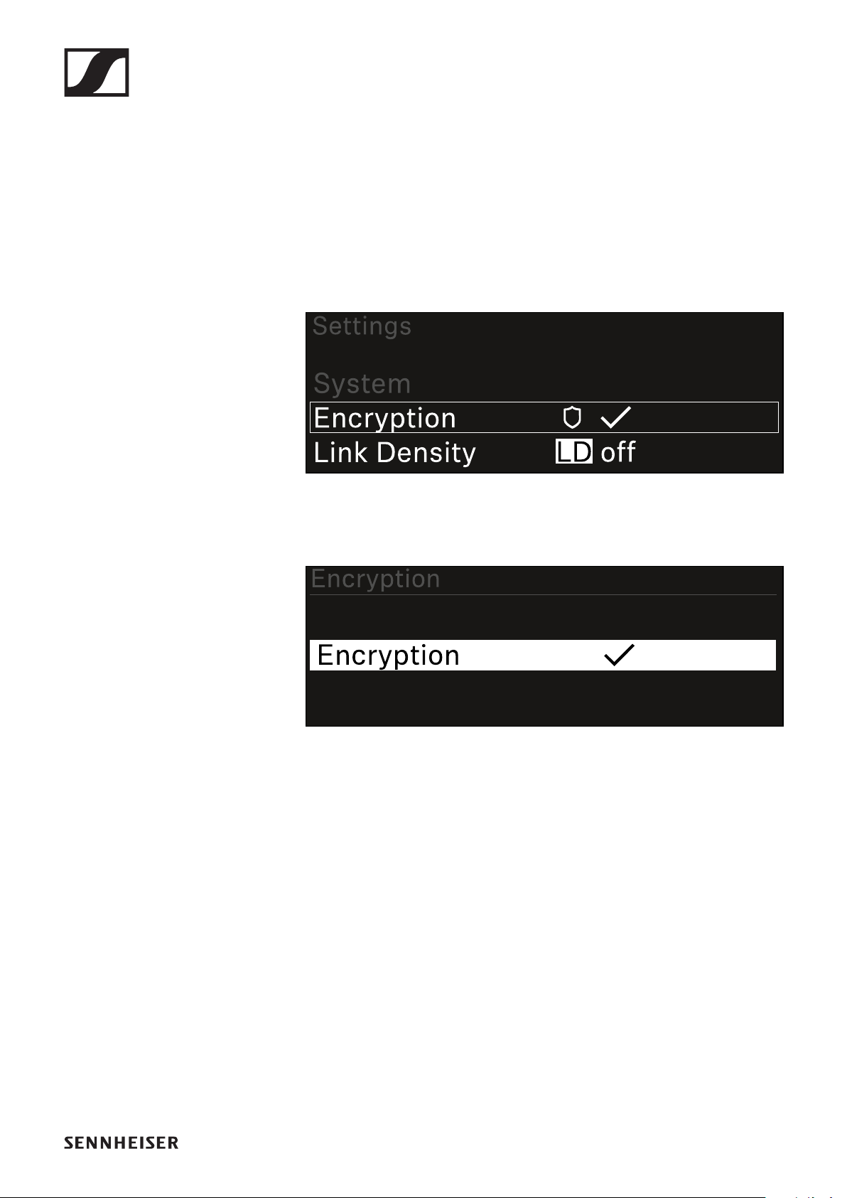
EW-DX EM 2 rack receiver
140
System -> Encryption menu item
You can secure the radio link between the transmitter and re-
ceiver using AES 256 encryption.
To open the Encryption menu item:
▷In the System menu, navigate to the Encryption menu
item.
▷Press the jog dial to open the menu.
The following view is displayed:
▷Turn the jog dial to choose between the On and Off op-
tions.
▷Press the jog dial to save your setting.
After enabling AES 256 encryption, the connected transmitter
must be resynchronized with the receiver to enable encryption
on the transmitter as well.
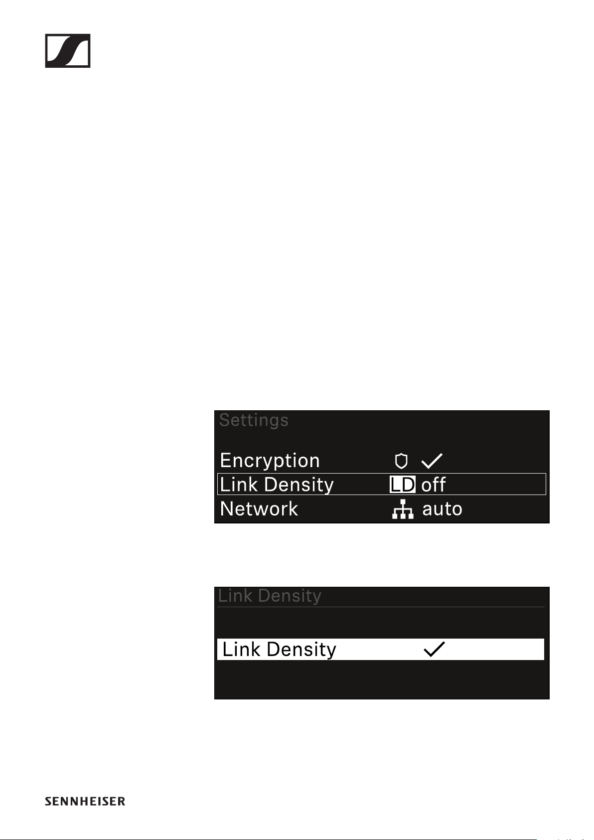
EW-DX EM 2 rack receiver
141
System -> Link Density menu item
Link Density mode (LD mode)
LD mode doubles the number of usable carrier frequencies in
the available spectrum, as the minimum distance for the equi-
distant frequency grid is halved.
This is achieved by reducing the modulation bandwidth of the
transmitter. This means that a much smaller frequency spac-
ing between neighboring frequencies can be selected, and
therefore more frequencies can be used in the same available
spectrum without intermodulation.
LD mode is recommended if the following criteria are met:
•The required number of channels cannot be achieved using
the normal mode, as there may be only a small spectrum
available.
•The distance between the transmitters and the antennas is
not too great.
To open the Link Density menu item:
▷In the System menu, navigate to the Link Density menu
item.
▷Press the jog dial to open the menu.
The following view is displayed:
▷Turn the jog dial to choose between the On and Off op-
tions.
▷Press the jog dial to save your setting.
▷If you have enabled LD mode, the receiver must be restart-
ed.
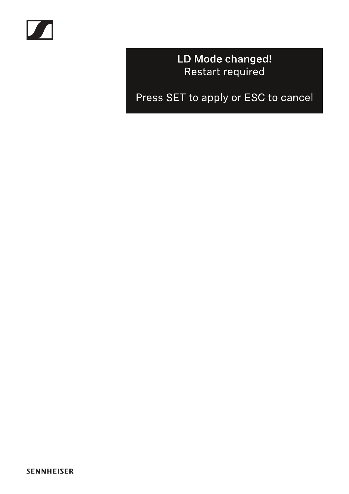
EW-DX EM 2 rack receiver
142
▷Press the jog dial to restart the receiver.
or
▷Press the ESC button to cancel the mode change.
After enabling LD mode and restarting the receiver, the con-
nected transmitter must be resynchronized with the receiver
to enable LD mode on the transmitter as well.
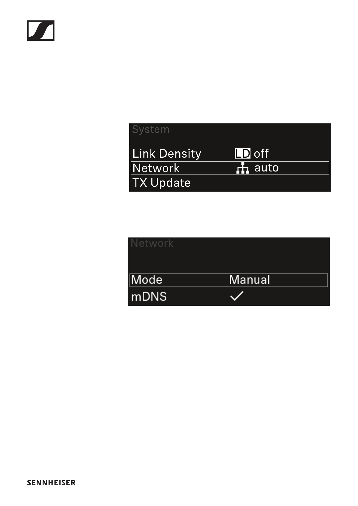
EW-DX EM 2 rack receiver
143
System -> Network menu item
In this menu item, you can configure the settings for the net-
work connection.
To open the Network menu item:
▷In the System menu, navigate to the Network menu item.
▷Press the jog dial to open the menu.
▷Rotate the jog dial to navigate through the Network menu
and select the desired menu item.
You can make the following settings here:
Mode
•Auto: The network configuration is performed automatical-
ly.
•Manual: The network configuration can be performed man-
ually.
mDNS
You can enable or disable this option if you want to use mDNS
for automatic device detection in the network.
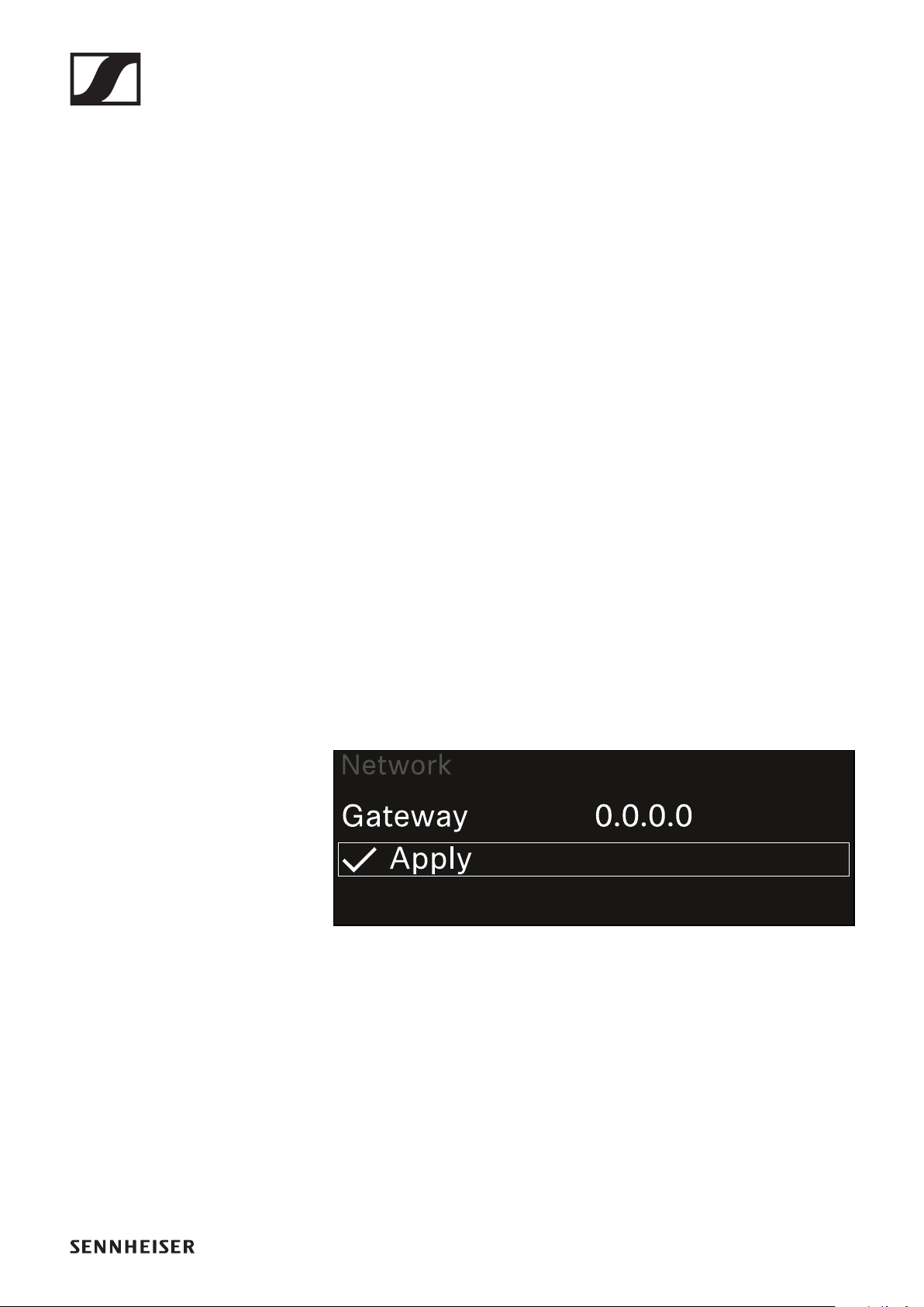
EW-DX EM 2 rack receiver
144
IP
•If the Mode option is set to Auto, the automatically as-
signed IP address is displayed here.
•If the Mode option is set to Manual, you can set the IP ad-
dress here.
Netmask
•If the Mode option is set to Auto, the automatically as-
signed netmask is displayed here.
•If the Mode option is set to Manual, you can set the net-
mask here.
Gateway
•If the Mode option is set to Auto, the automatically as-
signed gateway is displayed here.
•If the Mode option is set to Manual, you can set the gate-
way here.
Saving settings
To save the settings you have made:
▷Turn the jog dial until Apply appears in the selection frame.
▷Press the jog dial to save your settings.
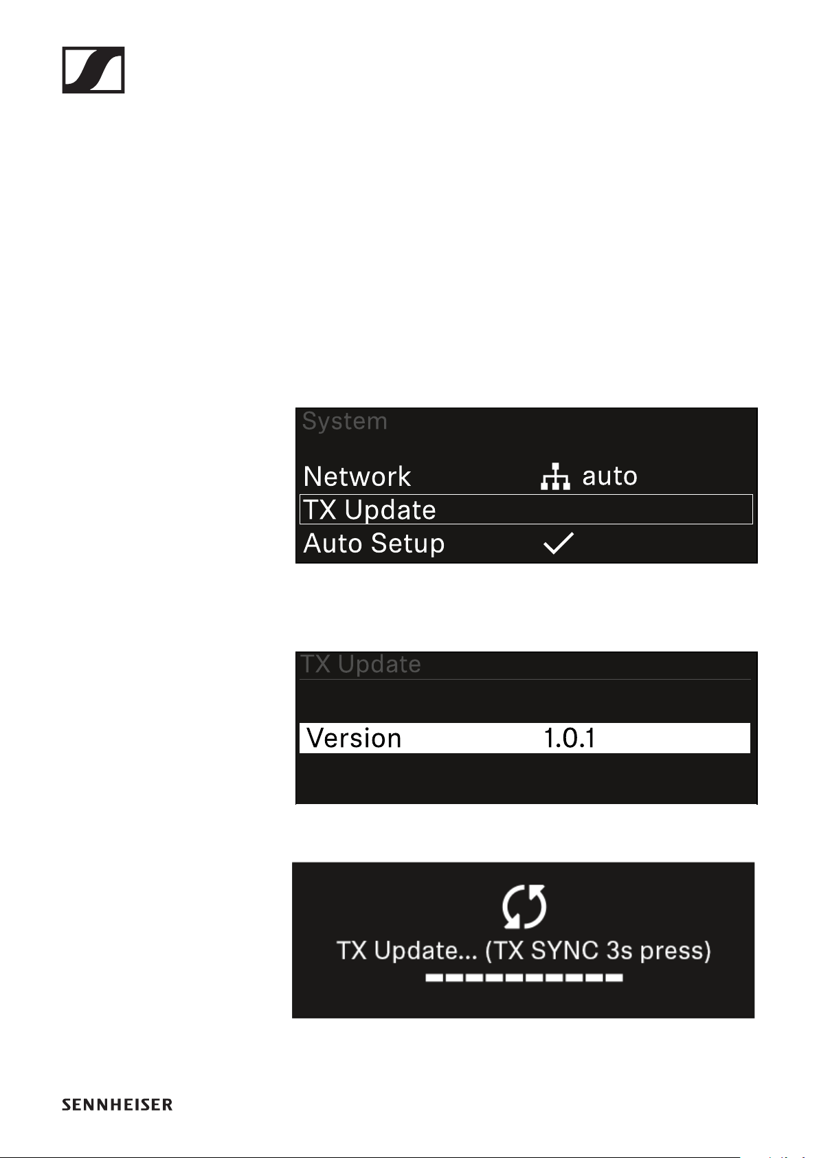
EW-DX EM 2 rack receiver
145
System -> TX Update menu item
This menu item lets you perform a firmware update for the
transmitters. This update is recommended after you perform a
firmware update for the receiver (see "Updating the firmware
of the receiver").
The firmware versions currently installed on the connected
transmitter can be viewed under the TX Software menu item
for the respective channel (see "Ch 1 / Ch 2 -> TX Software
menu item").
To open the TX Update menu item:
▷In the System menu, navigate to the TX Update menu item.
▷Press the jog dial to open the menu.
The available sender firmware is displayed:
▷Press the jog dial to start the firmware update.
▷Press the SYNC button on the connected transmitter for
3 seconds.
You have about 20 seconds to do this. The progress bar
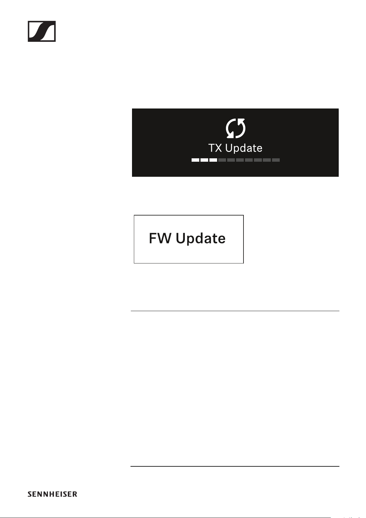
EW-DX EM 2 rack receiver
146
shows the remaining time.
The system carries out the firmware update for the trans-
mitter.
The progress of the update is shown on the receiver’s display.
The transmitter’s display shows that the firmware update is in
progress.
ATTENTION
Canceling the update can impair the function of the transmit-
ter
If the transmitter is turned off during the firmware update, the
update may fail and the transmitter may cease to function cor-
rectly.
▷Do not turn off the transmitter during the update.
▷Do not remove the batteries or rechargeable battery pack
during the update.
▷Make sure that the transmitter’s (rechargeable) batteries
are sufficiently charged before updating.
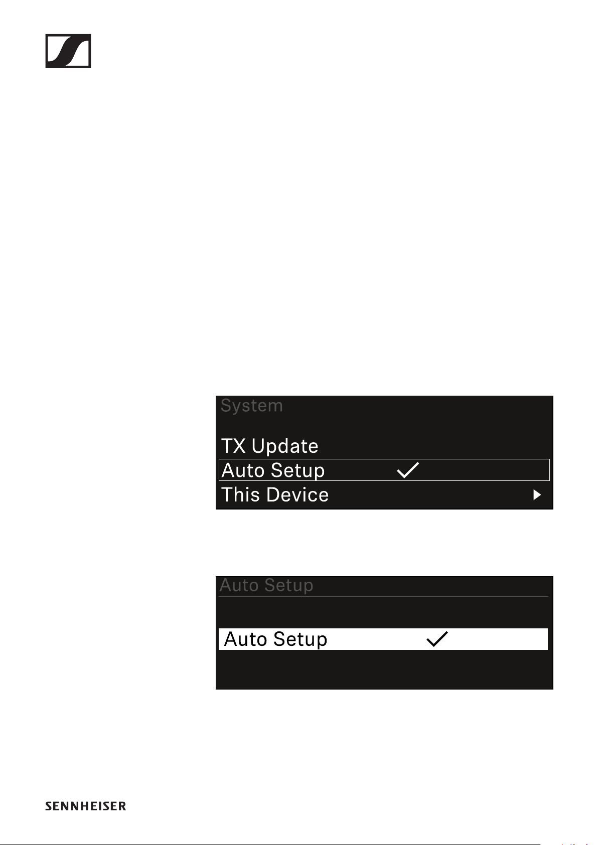
EW-DX EM 2 rack receiver
147
System -> Auto Setup menu item
In this menu item, you can activate the Auto Setup function
for the receiver.
If the function is activated here, you can perform an automatic
frequency setup for both channels of this receiver via the Scan
/ Auto Setup menu item.
See "Ch 1 / Ch 2 -> Scan / Auto Setup menu item".
The receiver will also be enabled for automatic frequency set-
up in a network consisting of multiple receivers.
If the function is disabled here, you can only assign a frequen-
cy to the selected channel of the receiver via the Scan / Auto
Setup menu item.
To open the Auto Setup menu item:
▷In the System menu, navigate to the Auto Setup menu
item.
▷Press the jog dial to open the menu.
The following view is displayed:
▷Turn the jog dial to choose between the On and Off op-
tions.
▷Press the jog dial to save your setting.
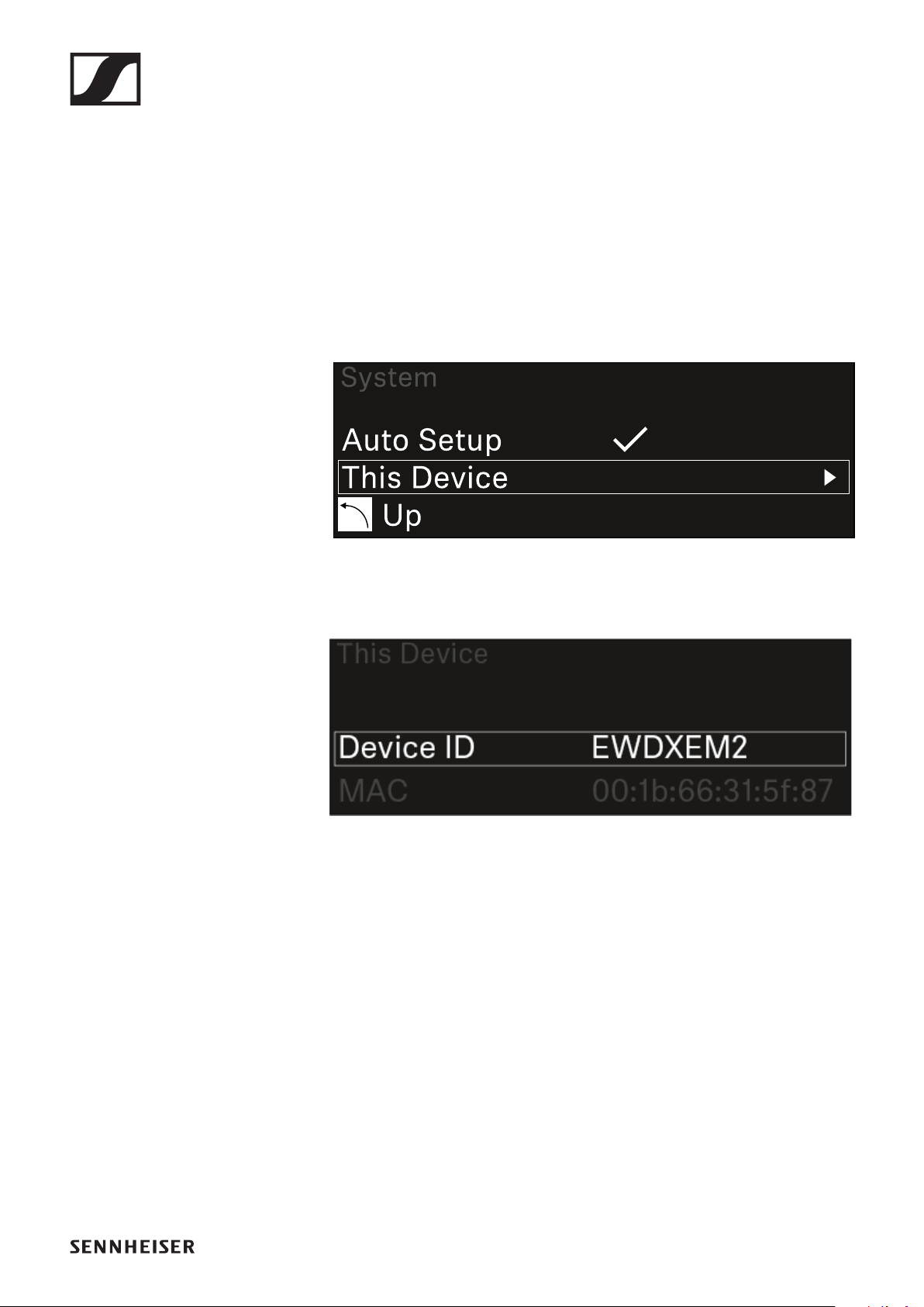
EW-DX EM 2 rack receiver
148
System -> This Device menu item
This menu item allows you to change the device name, view
software and hardware information, or reset the device to fac-
tory settings.
To open the This Device menu item:
▷In the System menu, navigate to the This Device menu
item.
▷Press the jog dial to open the menu.
The following view is displayed:
▷Choose from the following:
•Device ID: Open this menu item to change the device name.
This receiver will be displayed in the network under this
name.
•MAC: Shows the MAC address of the receiver.
•Software: Shows the software version of the receiver.
•HW Main/HW Front/HW Tuner: Displays the hardware
versions of the boards installed in the receiver.
•Reset: Resets the receiver to factory settings.

EW-DX EM 2 rack receiver
149
Updating the firmware of the receiver
You can update the receiver firmware using the Sennheiser
Control Cockpit software or the Wireless Systems Manager
software.
▷To do so, connect the receiver to a network (see "Connect-
ing receivers in a network") and establish the connection
with the software.
For more information about controlling devices with the Senn-
heiser Control Cockpit or Wireless Systems Manager soft-
ware, refer to the software help.
You can download the software here:
www.sennheiser.com/control-cockpit-software
www.sennheiser.com/wsm
To update the transmitter’s firmware, go to System -> TX Up-
date in the menu on the receiver. See "System -> TX Update
menu item".
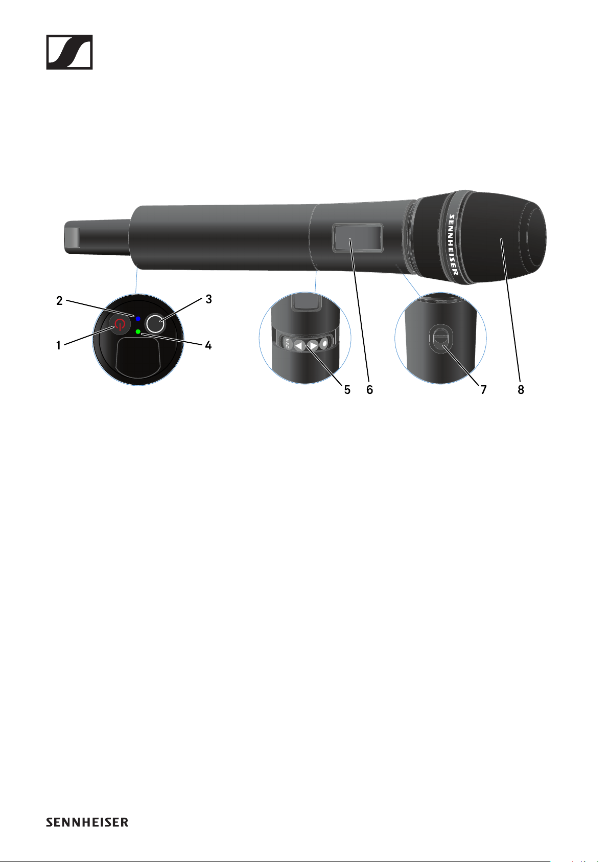
EW-DX SKM | EW-DX SKM-S handheld transmitter
150
EW-DX SKM | EW-DX SKM-S handheld
transmitter
Product overview
►
1ON/OFF button
•See "Switching the handheld transmitter on and off"
2DATA LED
•See "Meaning of the LEDs"
3SYNC button
•See "Establishing a connection to the receiver"
4LINK LED
•See "Meaning of the LEDs"
5Function buttons for navigating the menu
•See "Buttons for navigating the handheld transmitter’s
menu"
6Display panel
•See "Information on the handheld transmitter’s display"
7Mute switch (EW-DX SKM-S only)
•See "Configuring mute mode and muting the handheld
transmitter (EW-DX SKM-S only)"
8Microphone module
•See "Replacing the microphone module"
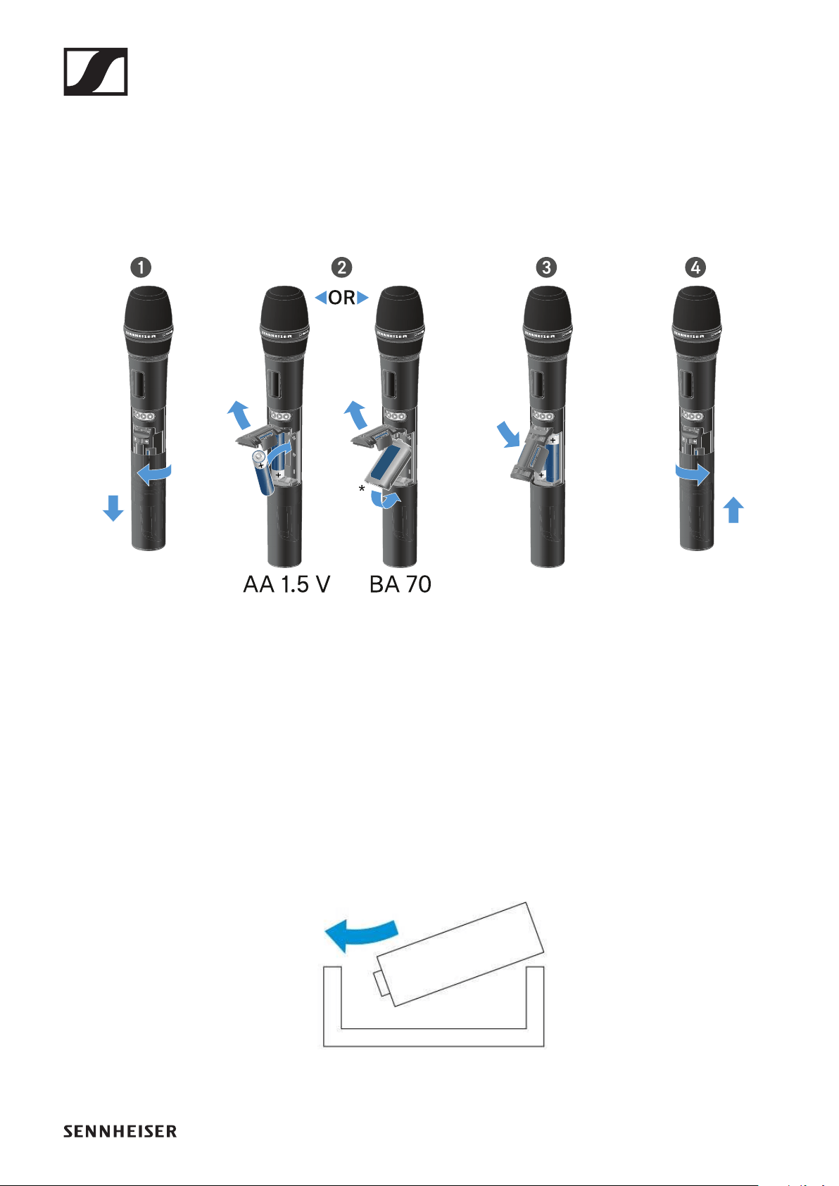
EW-DX SKM | EW-DX SKM-S handheld transmitter
151
Inserting and removing the batteries/re-
chargeable batteries
You can operate the handheld transmitter either with batteries
(AA, 1.5 V) or with the rechargeable Sennheiser BA 70 battery.
▷Unscrew the microphone housing as shown in the figure
and pull it down as far as it will go.
▷Insert the batteries or the BA 70 rechargeable battery as in-
dicated in the battery compartment. Observe correct polar-
ity.
▷Screw the microphone housing back on.
Note about the BA 70 rechargeable battery
▷Make sure that the BA 70 rechargeable battery is inserted
as follows:
►
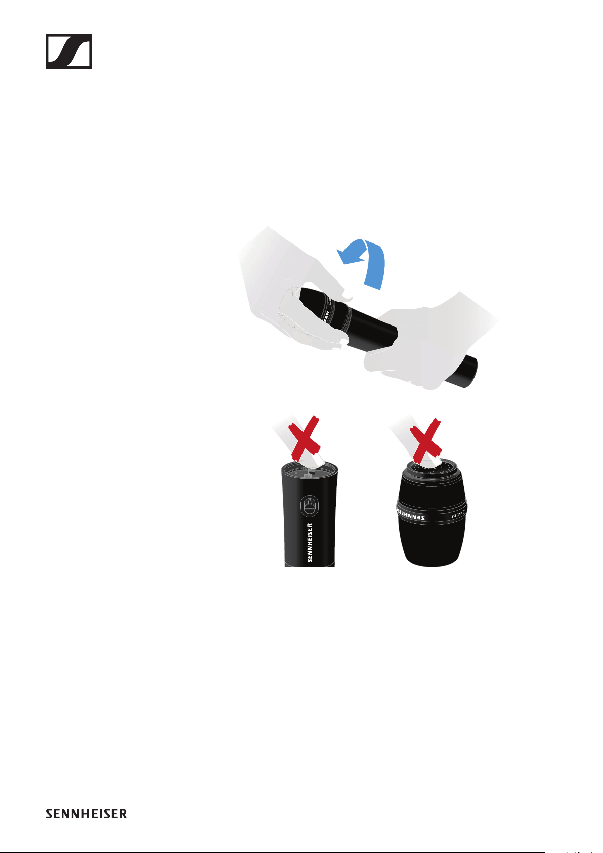
EW-DX SKM | EW-DX SKM-S handheld transmitter
152
Replacing the microphone module
To replace the microphone module:
▷Unscrew the microphone module.
▷Screw the desired microphone module on.
▷Do not touch the wireless microphone contacts or the mi-
crophone module contacts. If you touch the contacts, they
may become dirty or bent.
►
Compatible microphone modules
The following microphone modules are compatible with the
handheld transmitter:
•MMD 835-1 | Dynamic microphone module with cardioid
pattern
•MMD 845-1 | Dynamic microphone module with super-car-
dioid pick-up pattern
•MME 865-1 | Condenser microphone module with super-
cardioid pick-up pattern
•MMD 935-1 | Dynamic microphone module with cardioid
pattern

EW-DX SKM | EW-DX SKM-S handheld transmitter
153
•MMD 945-1 | Dynamic microphone module with super-car-
dioid pick-up pattern
•MMK 965-1 | Condenser microphone module with select-
able pattern: cardioid and super-cardioid
•MMD 42-1 | Dynamic microphone module with omni-direc-
tional pattern
•Neumann KK 204 | Condenser microphone module with
cardioid pattern
•Neumann KK 205 | Condenser microphone module with su-
per-cardioid pick-up pattern
•MM 435 | Dynamic microphone module with cardioid pat-
tern
•MM 445 | Dynamic microphone module with super-cardioid
pick-up pattern
•ME 9002 | Condenser microphone module with omni-direc-
tional pattern
•ME 9004 | Condenser microphone module with cardioid
pattern
•ME 9005 | Condenser microphone module with super-car-
dioid pick-up pattern
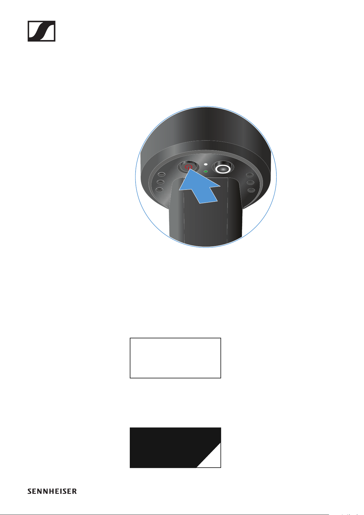
EW-DX SKM | EW-DX SKM-S handheld transmitter
154
Switching the handheld transmitter on and
off
To switch the handheld transmitter on:
▷Short-press the ON/OFF button.
The LINK LED lights up and the transmitter switches on.
►
To switch the handheld transmitter off:
▷Hold down the ON/OFF button until the LEDs switch off.
Note that the transmitter’s permanent E-Ink display still dis-
plays the parameters after it is switched off.
►
EW-DX 1
510.100
EW-DX 1
510.100
off
Display when transmitter is switched on:
Display when transmitter is switched off:

EW-DX SKM | EW-DX SKM-S handheld transmitter
155
Checking the battery status of the transmit-
ter (Check function)
To check the battery status of the transmitter:
▷Short-press the ON/OFF button on the transmitter.
►
The transmitter’s LINK LED flashes to indicate the current
charge level of the battery or the BA 70 rechargeable battery.
►
In addition, the battery status is displayed on the transmitter
display for approx. 5 seconds.
Pressing the transmitter’s ON/OFF button will simultaneously
trigger the Identify function: "Identifying the paired receiver
(Identify function)".
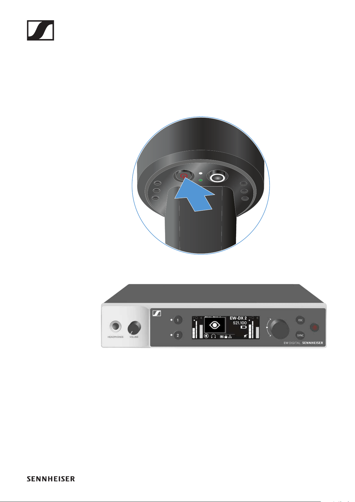
EW-DX SKM | EW-DX SKM-S handheld transmitter
156
Identifying the paired receiver (Identify func-
tion)
In multi-channel systems, you can use the Check function to
quickly identify to which receiver the transmitter is paired.
Both the transmitter and receiver must be switched on.
▷Short-press the ON/OFF button on the transmitter.
►
An eye flashes next to the respective receiving channel on
the coupled receiver’s display.
►
Pressing the transmitter’s ON/OFF button will simultaneously
trigger the Check function: "Checking the battery status of the
transmitter (Check function)".
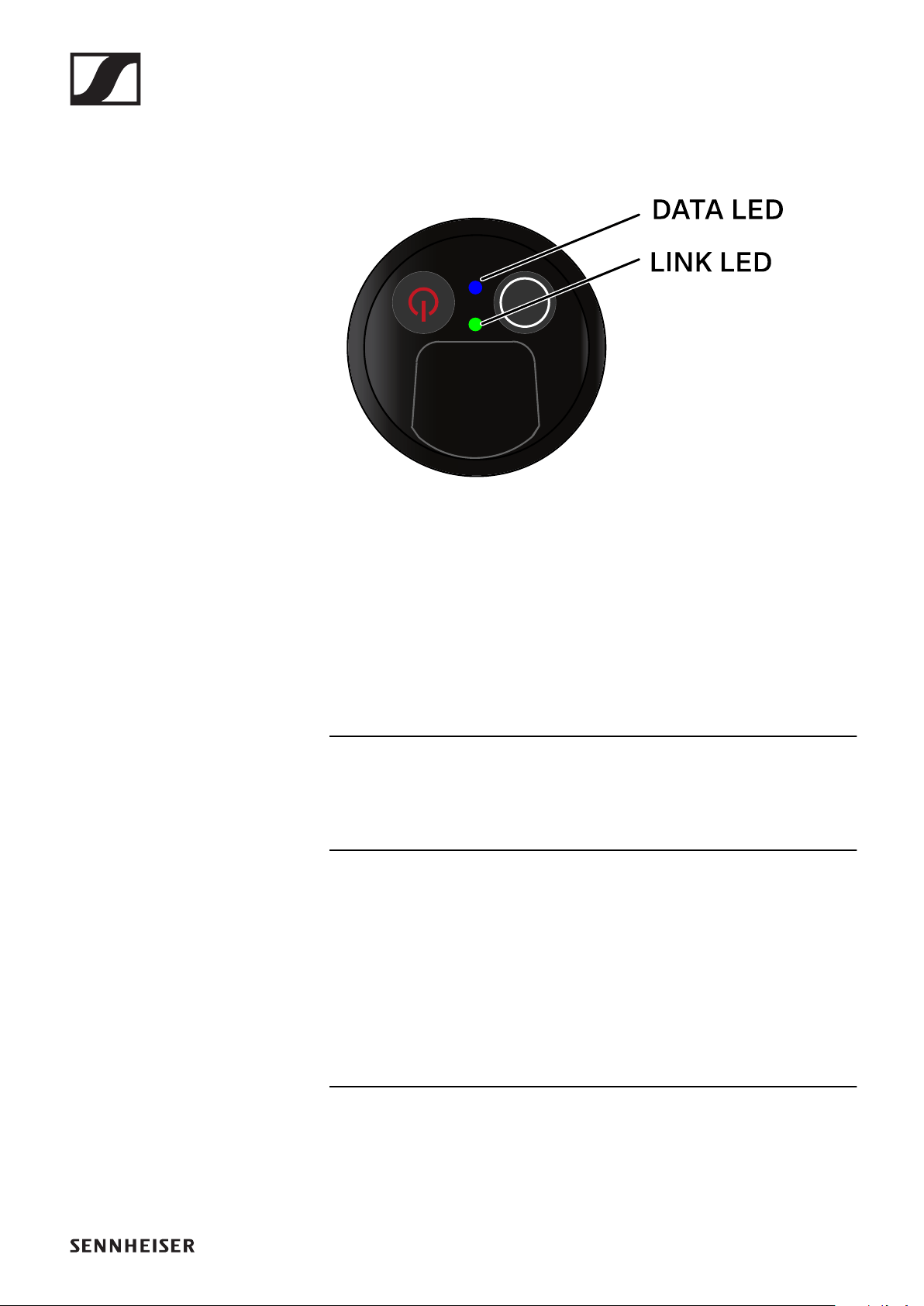
EW-DX SKM | EW-DX SKM-S handheld transmitter
157
Meaning of the LEDs
The LINK and DATA LEDs on the bottom of the transmitter can
indicate the following information.
LINK LED
The LINK LED provides information about the status of the ra-
dio link between the transmitter and receiver, as well as status
information for the transmitter.
The LED is green:
▷The transmission frequency is active.
The LED is yellow:
▷The link between the transmitter and receiver is estab-
lished.
▷The audio signal is muted.
or
▷No microphone module is mounted on the SKM-S handheld
transmitter.
The LED is flashing yellow:
▷The link between the transmitter and receiver is estab-
lished.
▷The audio signal is overdriven (clipping).
EW-DX SKM | EW-DX SKM-S handheld transmitter
158
The LED is continuously red:
▷The (rechargeable) battery in the transmitter is dead.
The LED is flashing red:
▷The link between the transmitter and receiver is estab-
lished.
▷The battery/rechargeable battery in the transmitter is low.
The LED is off:
▷No link between the transmitter and receiver.
▷The transmitter is switched off.
DATA LED
The DATA LED provides information about the synchroniza-
tion of transmitters and receivers.
The LED is flashing blue:
▷The transmitter is being synchronized with a receiver.
The LED is continuously blue:
▷The firmware is being updated.
The LED is off:
▷There is currently no active data link.

EW-DX SKM | EW-DX SKM-S handheld transmitter
159
Establishing a connection to the receiver
To establish a radio link between the transmitter and the re-
ceiver, the two devices must be set to the same frequency.
See "Establishing a radio link | Synchronizing the receiver and
transmitter".
Conditions and restrictions for using frequencies
There may be special conditions and restrictions for using fre-
quencies in your country.
Before putting the product into operation, find the information
for your country at the following address:
www.sennheiser.com/sifa

EW-DX SKM | EW-DX SKM-S handheld transmitter
160
Information on the handheld transmitter’s
display
You can view the following information on the transmitter dis-
play.
Further information
Link name:
You can assign a name to the radio link in the transmitter’s
menu (see "Name menu item").
Alternatively, you can assign the name in the receiver’s menu
and then synchronize it to the transmitter (see "Ch 1 / Ch 2 ->
Name menu item").
Frequency:
You can manually set the frequency of the radio link in the
transmitter’s menu (see "Frequency menu item").
The frequency of the radio link can also be set manually in the
receiver’s menu (see "Ch 1 / Ch 2 -> Frequency menu item") or
via the Auto Setup function (see "Ch 1 / Ch 2 -> Scan / Auto
Setup menu item") and then synchronized to the transmitter.
EW-DX 1
510.100
6:43
System
icons
Frequency
Link name
Battery status
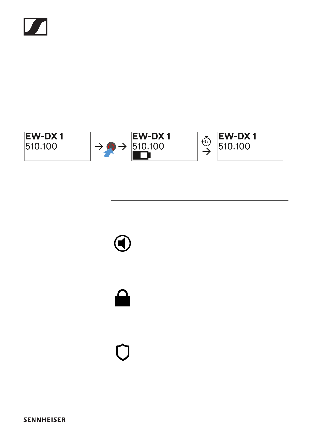
EW-DX SKM | EW-DX SKM-S handheld transmitter
161
Battery status:
Displays the charging status of the batteries or the BA 70 bat-
tery pack.
When using the BA 70 rechargeable battery, the remaining
runtime is also displayed in hours and minutes.
The battery status is hidden in the display’s default state.
Short-press the On/Off button on the transmitter (Check
function, see "Checking the battery status of the transmitter
(Check function)") to display the battery status for approx. 5
seconds.
System icons:
The transmitter’s mute switch is deactivated. See "Mute But-
ton menu item (only EW-DX SKM-S)".
The Auto Lock function is activated. See "Auto Lock menu
item".
AES 256 encryption is enabled. See "System -> Encryption
menu item".
EW-DX SKM | EW-DX SKM-S handheld transmitter
162
Note that the transmitter’s permanent E-Ink display still dis-
plays the parameters after it is switched off.
EW-DX 1
510.100
EW-DX 1
510.100
off
Display when transmitter is switched on:
Display when transmitter is switched off:
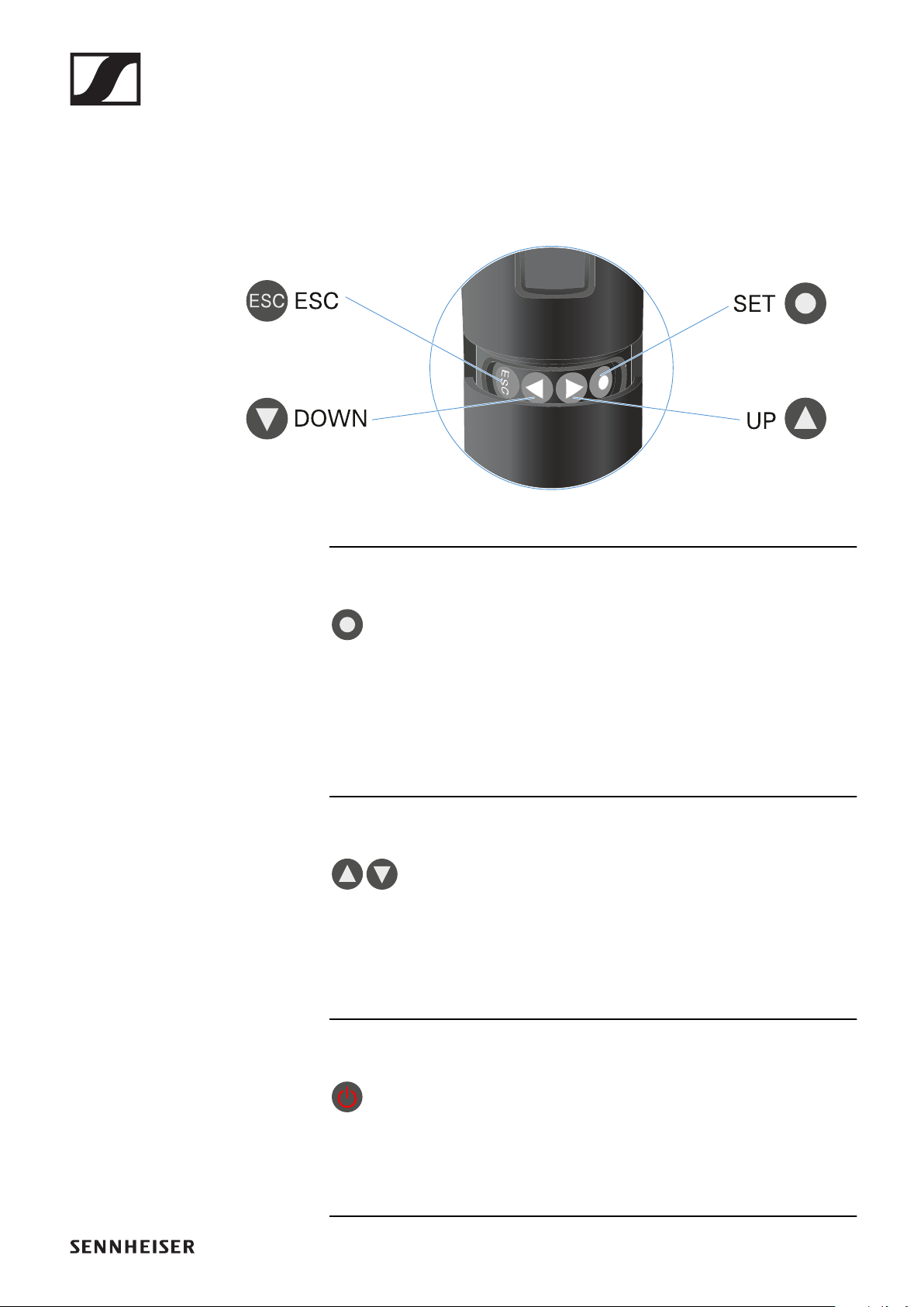
EW-DX SKM | EW-DX SKM-S handheld transmitter
163
Buttons for navigating the handheld trans-
mitter’s menu
Use the following buttons to navigate through the transmit-
ter’s operating menu.
►
Press the SET button
•Jumps from the home screen to the operating menu
•Calls up a menu item
•Saves settings
Press the UP or DOWN button
•Changes to the previous or next menu item
•Changes the setting of a menu item
Press the ESC (ON/OFF) button
•Cancels the entry and returns to the previous display
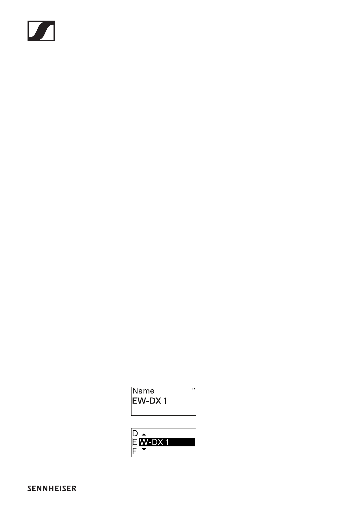
EW-DX SKM | EW-DX SKM-S handheld transmitter
164
Making settings in the menu of the handheld
transmitter
Navigating through the menu
To open the menu:
▷Press the SET button.
The operating menu is shown on the transmitter display
panel.
To open a menu item:
Press the UP or DOWN buttons to navigate through the in-
dividual menu items.
Press the SET button to open the selected menu item.
▷"Buttons for navigating the menu of the bodypack transmit-
ter"
Making changes in a menu item
After you open a menu item, you can make changes as follows:
▷Press the UP or DOWN buttons to set the displayed value.
▷Press the SET button to save the setting.
▷Press the ESC button to leave the menu item without sav-
ing the setting.
▷"Buttons for navigating the menu of the bodypack transmit-
ter"
Menu item overview
In the menu items, you can configure the settings below and
display information.
Name menu item
You can enter the name of the link in this
menu item.
▷Press the UP or DOWN buttons to select a character.
▷Press the SET button to go to the next position.
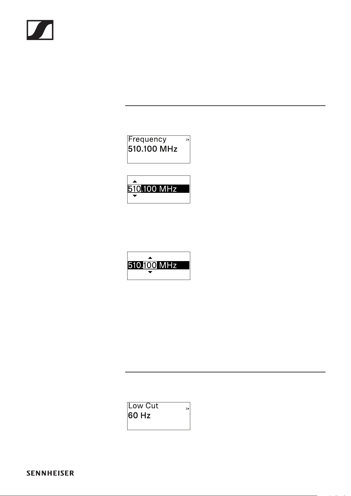
EW-DX SKM | EW-DX SKM-S handheld transmitter
165
▷At the last position, press the SET button to save the se-
lected name.
If you enter a name for the radio link in the Name menu item
on the receiver and then synchronize the receiving channel
with the transmitter, the name entered in the transmitter is
overwritten with the name entered in the receiver.
Frequency menu item
In this menu item, you can set the trans-
mitter’s transmission frequency.
▷Press the UP or DOWN button to set the frequency’s MHz
range.
▷Press the SET button to confirm your selection.
▷Press the UP or DOWN button to set the frequency’s kHz
range.
▷Press the SET button to save the set frequency.
If you set a frequency for the channel using the Frequency
menu item on the receiver or via the Scan / Auto Setup func-
tion and then synchronize the receiving channel with the
transmitter, the frequency entered in the transmitter is over-
written by the frequency set in the receiver.
Low Cut menu item
In this menu item, you can adjust the
value for the low cut filter.
•Setting range: 60 Hz, 80 Hz, 100 Hz, 120 Hz
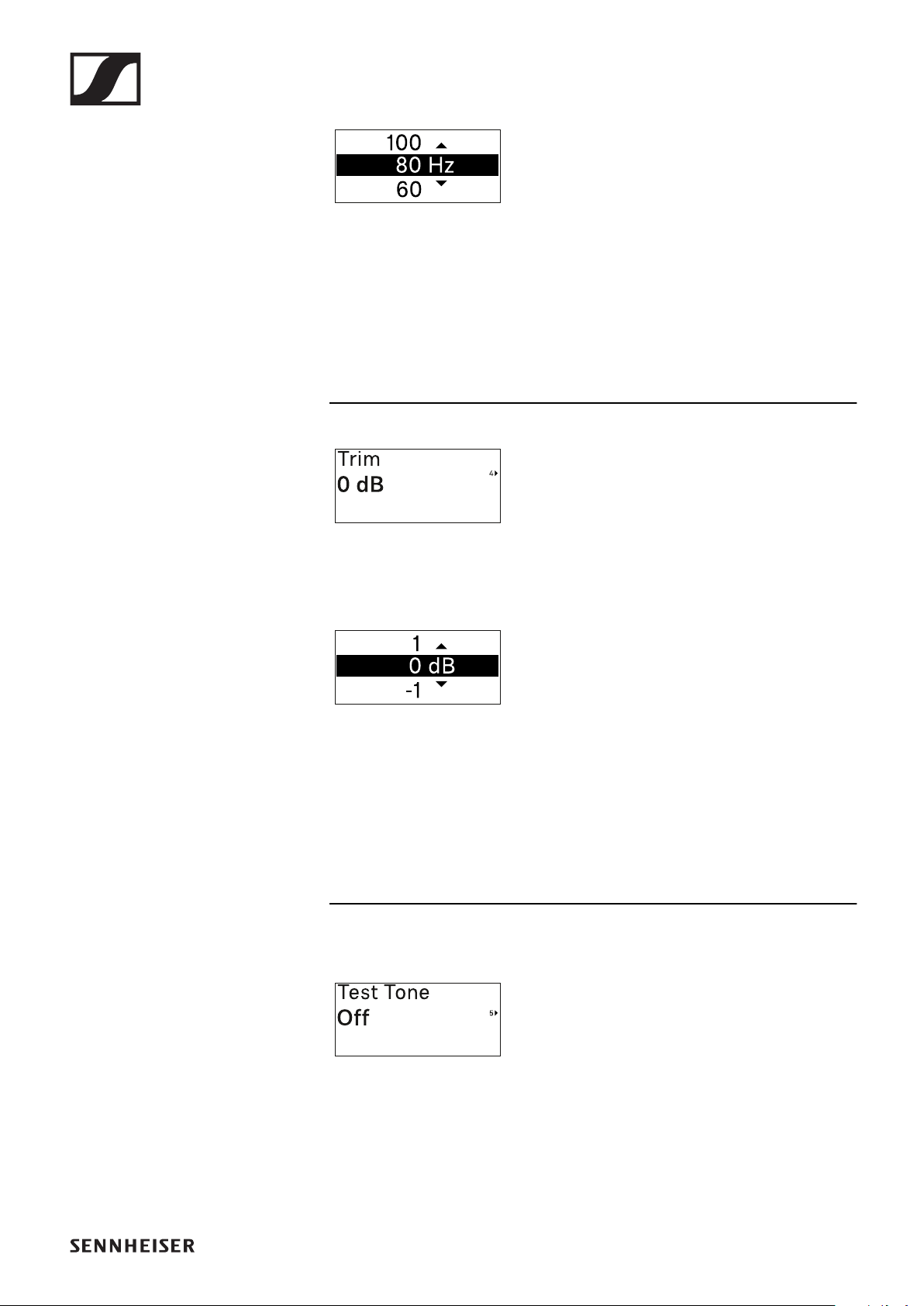
EW-DX SKM | EW-DX SKM-S handheld transmitter
166
▷Press the UP or DOWN button to set the desired value.
▷Press the SET button to confirm your selection.
If you set a value for the channel’s low cut filter using the Low
Cut menu item on the receiver and then synchronize the re-
ceiving channel with the transmitter, the value entered in the
transmitter is overwritten by the value set in the receiver.
Trim menu item
In this menu item, you can adjust the au-
dio level of the transmitter as well as the
gain of the wireless link (can be set only
on the receiver) to suit input signals of different volumes.
•Setting range: -12 dB to +6 dB in increments of 1 dB
▷Press the UP or DOWN button to set the desired value.
▷Press the SET button to confirm your selection.
If you set a value for the channel in the Trim menu item on the
receiver and then synchronize the receiving channel with the
transmitter, the value entered in the transmitter is overwritten
with the value entered in the receiver.
Test Tone menu item
In this menu item, you can activate a test
tone that the transmitter transmits in-
stead of the input signal. You can use
this feature to level out the system, for example.
•Setting range: Off, -90 dB to 0 dB in 6 dB increments
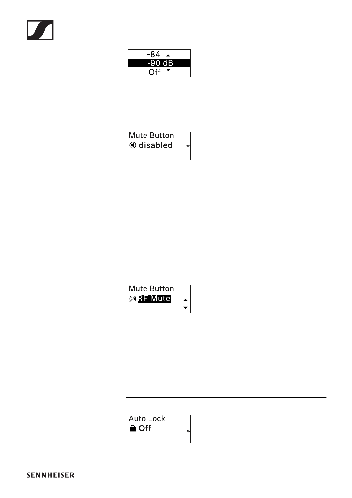
EW-DX SKM | EW-DX SKM-S handheld transmitter
167
▷Press the UP or DOWN button to set the desired value.
▷Press the SET button to confirm your selection.
Mute Button menu item (only EW-
DX SKM-S)
This function is only available for the EW-DX SKM-S version,
not for the EW-DX SKM version.
In this menu item you can set the function of the transmitter’s
mute switch.
•Setting range:
•Disabled: The mute switch has no function.
•RF Mute: The RF signal is deactivated when the mute
switch is on.
•AF Mute: The audio signal is muted when the mute switch
is on.
▷Press the UP or DOWN button to set the desired value.
▷Press the SET button to confirm your selection.
If you set a function for the transmitter’s mute switch in the
Mute Mode menu item on the receiver and then synchronize
the receiving channel with the transmitter, the value entered
in the transmitter is overwritten with the value entered in the
receiver.
Auto Lock menu item
In this menu item, you can activate or
deactivate the automatic lock-off for the
transmitter.

EW-DX SKM | EW-DX SKM-S handheld transmitter
168
The lock-off prevents the transmitter from being unintention-
ally switched off and also prevents any changes to the trans-
mitter’s menu.
If you want to change settings in the transmitter’s menu while
the lock-off is active, you have to temporarily disable the lock-
off. See .
▷Press the UP or DOWN button to set the desired value.
▷Press the SET button to confirm your selection.
If you set a value for the transmitter’s automatic lock-off in the
Auto Lock menu item on the receiver and then synchronize
the receiving channel with the transmitter, the value entered
in the transmitter is overwritten with the value entered in the
receiver.
Brightness menu item
In this menu item, you can adjust the
brightness of the transmitter’s display.
You can turn off the backlight complete-
ly or set it to one of five brightness levels.
▷Press the UP or DOWN button to set the desired value.
▷Press the SET button to confirm your selection.
LED menu item
This menu item allows you to set the be-
havior of the transmitter’s LINK LED.
•Setting range:
•ON: The LINK LED remains continuously lit.
•OFF: The LINK LED switches off while the lock-off func-
tion is active.
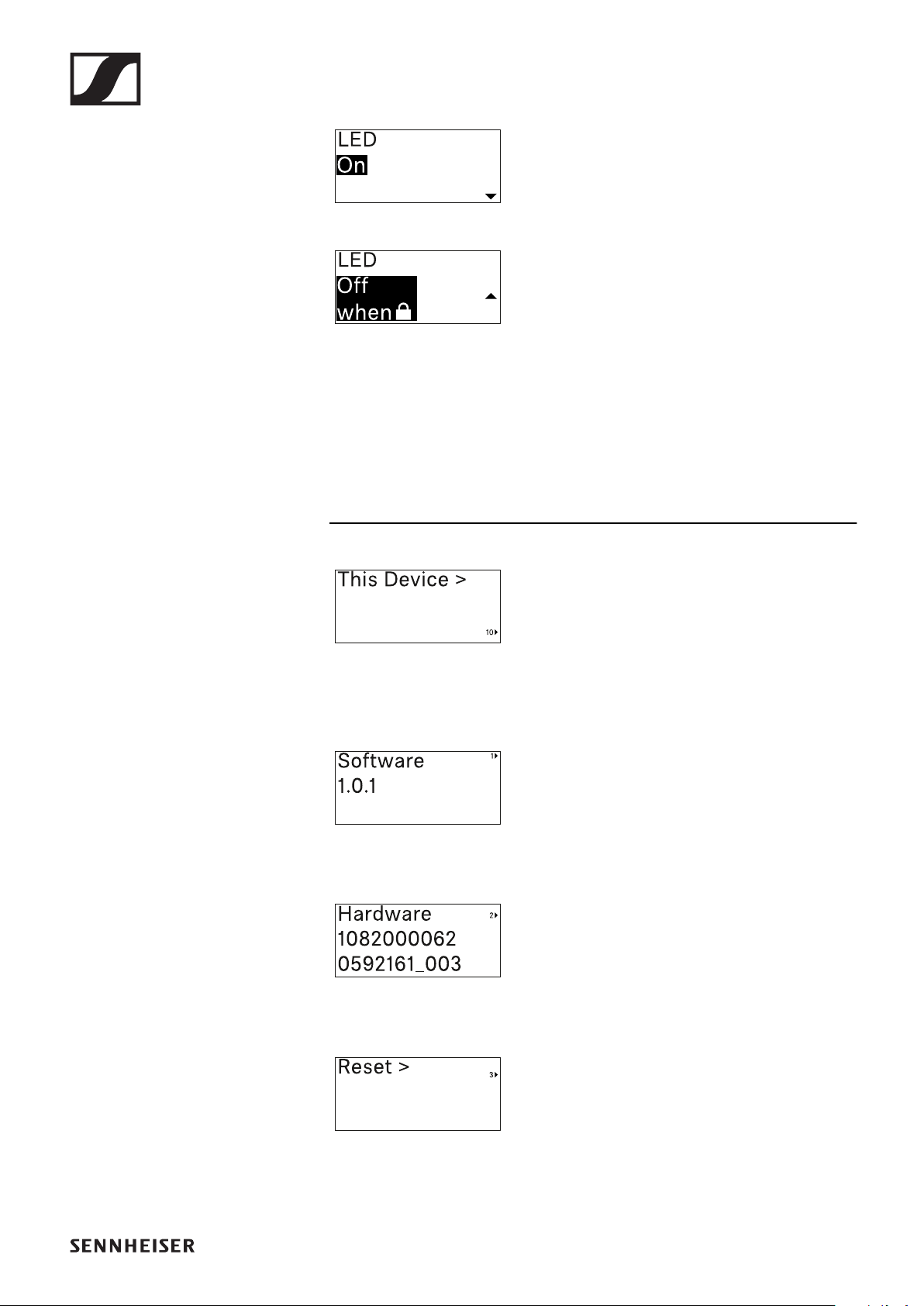
EW-DX SKM | EW-DX SKM-S handheld transmitter
169
▷Press the UP or DOWN button to set the desired value.
▷Press the SET button to confirm your selection.
If you set a function for the transmitter’s LINK LED in the LED
menu item on the receiver and then synchronize the receiving
channel with the transmitter, the value entered in the trans-
mitter is overwritten with the value entered in the receiver.
This Device menu item
In this menu item you can view informa-
tion about the transmitter’s software
and hardware and reset the transmitter
to the factory settings.
Show software
Shore hardware
Reset to factory settings
▷Press the SET button to open the Reset menu item.
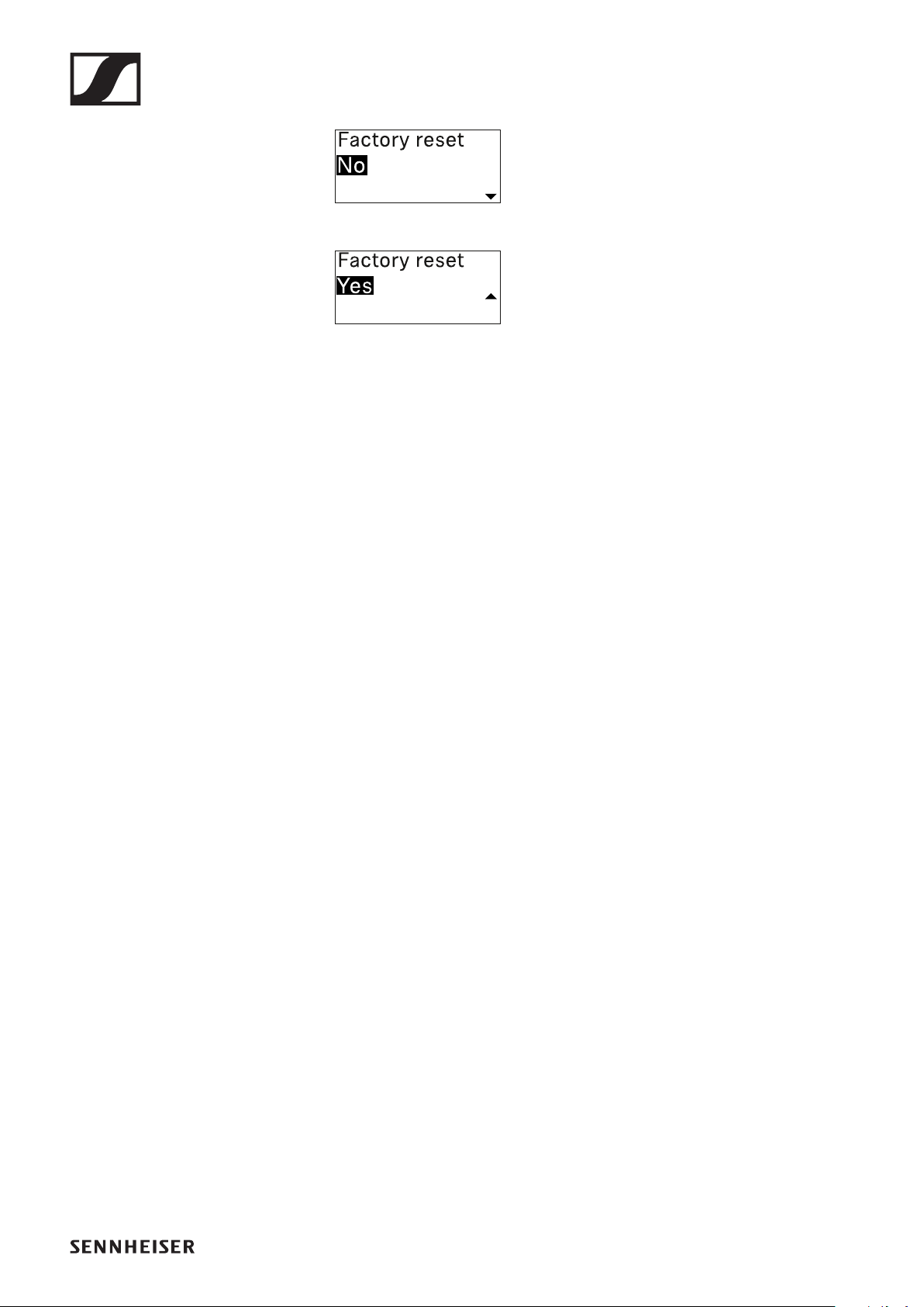
EW-DX SKM | EW-DX SKM-S handheld transmitter
170
▷Press the UP or DOWN button to set the desired value.
▷Press the SET button to confirm your selection.
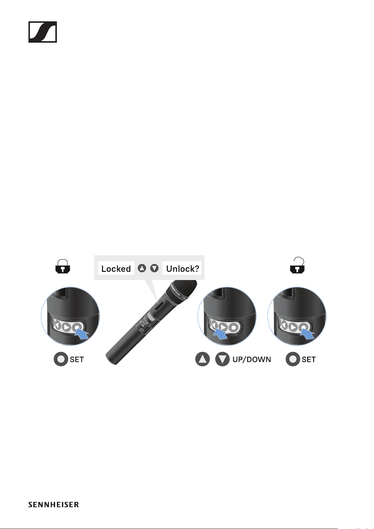
EW-DX SKM | EW-DX SKM-S handheld transmitter
171
Lock-off function
You can enable or disable the automatic lock-off function in
the Auto Lock menu item (see "Auto Lock menu item").
The lock-off function prevents the transmitter from being un-
intentionally switched off and also prevents any unintentional
changes to the transmitter’s configuration.
If you have enabled the Auto Lock function, you will have to
temporarily deactivate the lock-off function to operate the
transmitter.
To temporarily deactivate the lock-off function:
▷Press the SET button.
Locked appears in the display panel.
▷Press the UP or DOWN button.
Unlock? appears in the display panel.
▷Press the SET button.
Lock-off function is now temporarily deactivated.
The lock-off function remains deactivated while you are ac-
tively working in the operating menu.
After 10 seconds of inactivity, it automatically activates again.

EW-DX SKM | EW-DX SKM-S handheld transmitter
172
Configuring mute mode and muting the hand-
held transmitter (EW-DX SKM-S only)
This function is only available for the EW-DX SKM-S version,
not for the EW-DX SKM version.
You can mute the handheld transmitter by using the mute
switch to turn off either the audio signal (AF Mute) or the RF
signal (RF Mute).
To do this, you must configure the function of the mute switch
in the Mute Mode menu item.
▷On the receiver: "Ch 1 / Ch 2 -> Mute Mode menu item"
▷On the transmitter: "Mute Button menu item (only EW-
DX SKM-S)"
AF Mute
▷Slide the mute switch to the desired position to mute or ac-
tivate the audio signal.
RF Mute
▷Slide the mute switch to the desired position to activate or
deactivate the RF signal.
Updating the firmware of the transmitter
The transmitter firmware is updated via the receiver.
▷Update the transmitter firmware using the TX Update
menu item in the receiver’s System menu. See "System ->
TX Update menu item".
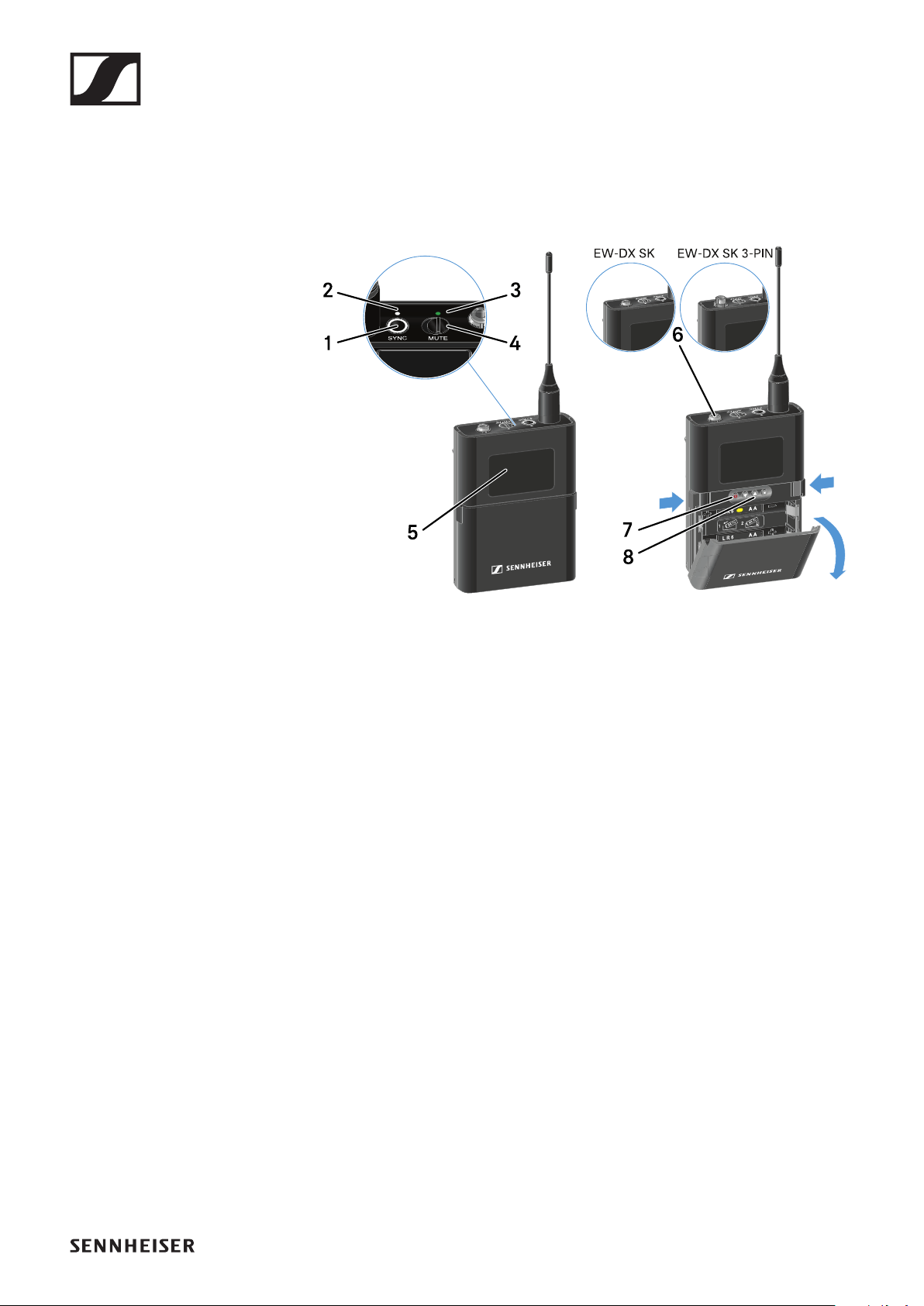
EW-DX SK | EW-DX SK 3-PIN bodypack transmitter
173
EW-DX SK | EW-DX SK 3-PIN bodypack
transmitter
Product overview
►
1SYNC button
•See "Establishing a radio link | Synchronizing the receiver
and transmitter"
2DATA LED
•See "Meaning of the LEDs"
3LINK LED
•See "Meaning of the LEDs"
4Mute switch
•See "Configuring mute mode and muting the bodypack
transmitter"
5Display panel
•See "Information on the bodypack transmitter’s display"
6EW-DX SK: 3.5 mm jack socket
EW-DX SK 3-PIN: 3-pin socket
•See "Connecting a microphone to the bodypack transmit-
ter"
•See "Connecting an instrument or line source to the
bodypack transmitter"
7ON/OFF button
•See "Switching the bodypack transmitter on and off"
8Function buttons for navigating the menu
•See "Buttons for navigating the menu of the bodypack
transmitter"
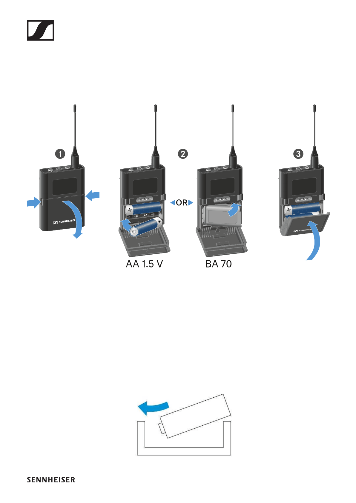
EW-DX SK | EW-DX SK 3-PIN bodypack transmitter
174
Inserting and removing the batteries/re-
chargeable batteries
You can operate the bodypack transmitter either with batter-
ies (AA, 1.5 V) or with the rechargeable Sennheiser BA 70 bat-
tery.
▷Press the two catches and open the battery compartment
cover.
▷Insert the batteries or the BA 70 rechargeable battery as in-
dicated in the battery compartment. Observe correct polar-
ity.
▷Close the battery compartment.
The cover locks into place with an audible click.
Note about the BA 70 rechargeable battery
▷Make sure that the BA 70 rechargeable battery is inserted
as follows:
►
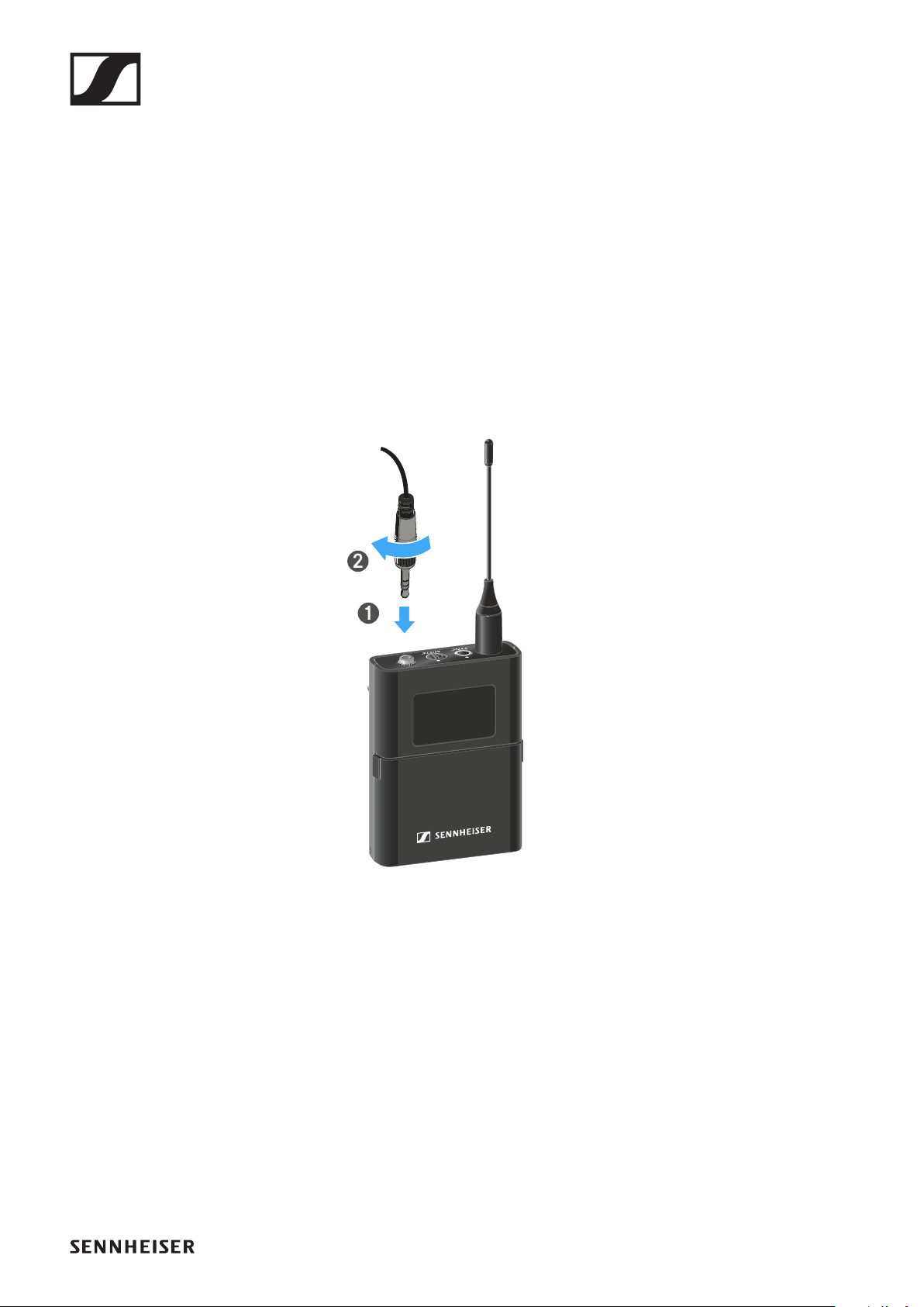
EW-DX SK | EW-DX SK 3-PIN bodypack transmitter
175
Connecting a microphone to the bodypack
transmitter
Connecting a microphone to the EW-DX SK
To connect a microphone to the EW-DX SK bodypack trans-
mitter:
▷Insert the cable’s 3.5 mm jack plug into the socket on the
bodypack transmitter as shown in the diagram.
▷Screw the plug’s coupling ring onto the audio socket thread
of the bodypack transmitter.
Compatible microphones
The following microphones are compatible with the EW-DX SK
bodypack transmitter:
Lavalier microphones:
•ME 2 | Lavalier microphone with omni-directional pattern
(models from 2021 and later with gold-plated plug*)
•ME 4 | Lavalier microphone with cardioid pattern (models
from 2021 and later with gold-plated plug*)
•MKE Essential Omni | Lavalier microphone with omni-di-
rectional pattern

EW-DX SK | EW-DX SK 3-PIN bodypack transmitter
176
•MKE 2 Gold | Lavalier microphone with omni-directional
pattern (models from 2018 and later with blue serial number
label)
•MKE 1 | Lavalier microphone with omni-directional pattern
•MKE mini | Lavalier microphone with omni-directional pat-
tern
Headset microphones:
•ME 3 | Headset microphone with cardioid pattern (models
from 2021 and later with gold-plated plug*)
•HSP Essential Omni | Headset microphone with omni-di-
rectional pattern
•HSP 2 | Headset microphone with omni-directional pattern
(models from March 2020 and later with code 1090 or high-
er)
•HS 2 | Headset microphone with omni-directional pattern
(models from 2021 and later with gold-plated plug*)
•SL Headmic 1 | Headset microphone with omni-directional
pattern
*Pre-2021 models with a nickel plug are not recommended.
They can pick up noise if they are placed too close to the trans-
mitter.

EW-DX SK | EW-DX SK 3-PIN bodypack transmitter
177
Connecting a microphone to the EW-DX SK 3-PIN
To connect a microphone to the EW-DX SK 3-PIN bodypack
transmitter:
▷Insert the cable’s three-pin plug into the socket on the
bodypack transmitter as shown in the diagram.
▷Screw the plug’s coupling ring onto the audio socket thread
of the bodypack transmitter.
Compatible microphones
The following microphones are compatible with the EW-
DX SK 3-PIN bodypack transmitter:
Lavalier microphones:
•MKE 1-4 | Lavalier microphone with omni-directional pat-
tern
•MKE 2-4 | Lavalier microphone with omni-directional pat-
tern
•MKE 40-4 | Lavalier microphone with cardioid pattern
•MKE Essential Omni Black-3-Pin | Lavalier microphone
with omni-directional pattern
•MKE Essential Omni Beige-3-Pin | Lavalier microphone
with omni-directional pattern

EW-DX SK | EW-DX SK 3-PIN bodypack transmitter
178
Headset microphones:
•HSP Essential Omni Black-3-Pin | Headset microphone
with omni-directional pattern
•HSP Essential Omni Beige-3-Pin | Headset microphone
with omni-directional pattern
•HSP 2 | Headset microphone with omni-directional pattern
•HSP 4 | Headset microphone with cardioid pattern
•SL Headmic 1-4 | Headset microphone with omni-direction-
al pattern

EW-DX SK | EW-DX SK 3-PIN bodypack transmitter
179
Connecting an instrument or line source to
the bodypack transmitter
Connecting an instrument or line source to the EW-
DX SK
You can connect instruments or audio sources with a line level
to the bodypack transmitter.
To do this, you will need the CI 1 (6.3 mm jack plug on a lock-
able 3.5 mm jack plug) or CL 2 (XLR-3F plug on a lockable 3.5
mm jack plug) Sennheiser cables.
To connect an instrument or line source to bodypack transmit-
ter:
▷Insert the cable’s 3.5 mm jack plug into the socket on the
bodypack transmitter as shown in the diagram.
▷Screw the plug’s coupling ring onto the audio socket thread
of the bodypack transmitter.
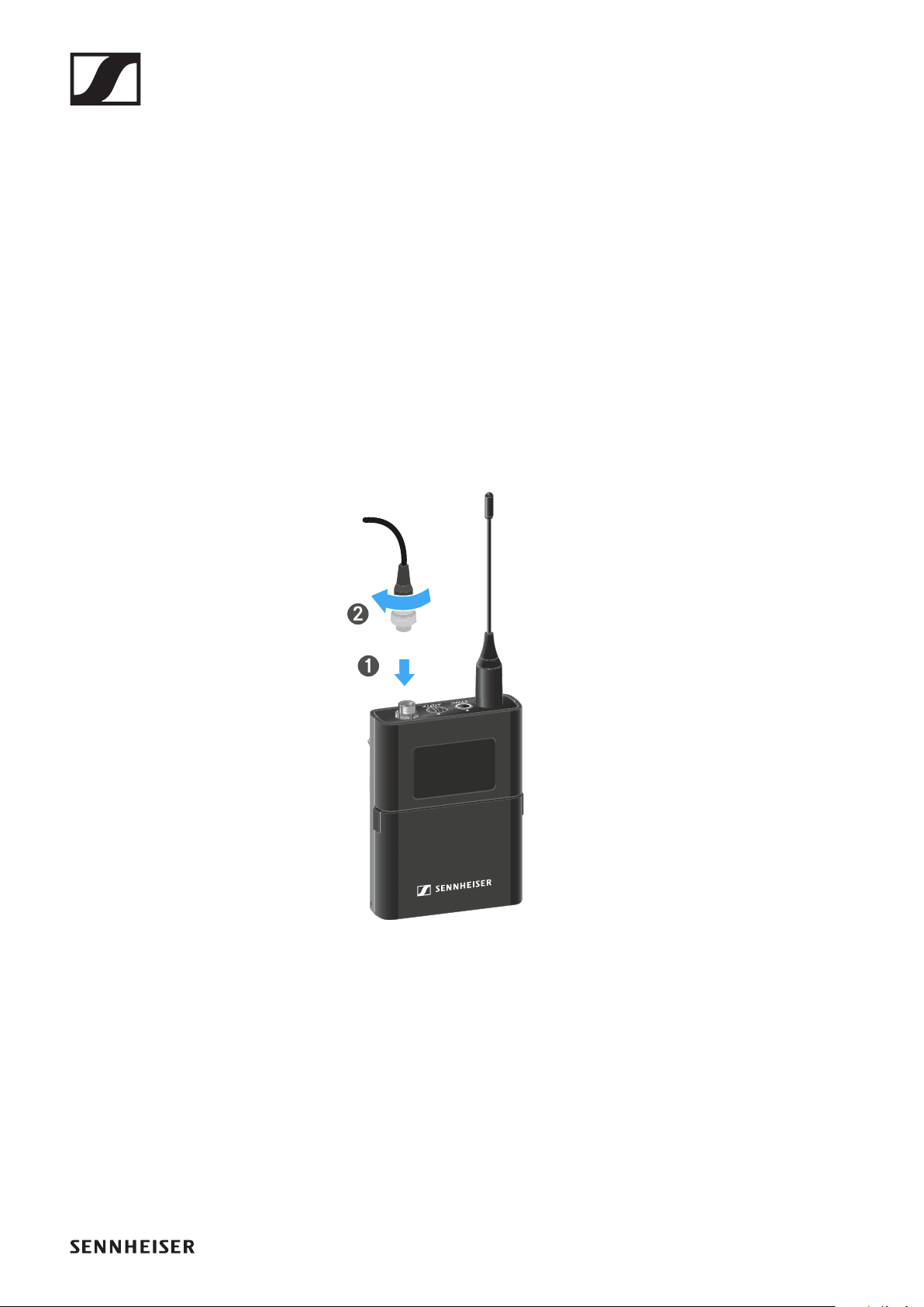
EW-DX SK | EW-DX SK 3-PIN bodypack transmitter
180
Connecting an instrument or line source to the EW-
DX SK 3-PIN
You can connect instruments or audio sources with a line level
to the bodypack transmitter.
To do so, you require the Sennheiser CI 1-4 cable (6.3 mm (1/
4") jack plug to screw-on 3-pin audio connector).
To connect an instrument or line source to bodypack transmit-
ter:
▷Insert the cable’s three-pin plug into the socket on the
bodypack transmitter as shown in the diagram.
▷Screw the plug’s coupling ring onto the audio socket thread
of the bodypack transmitter.
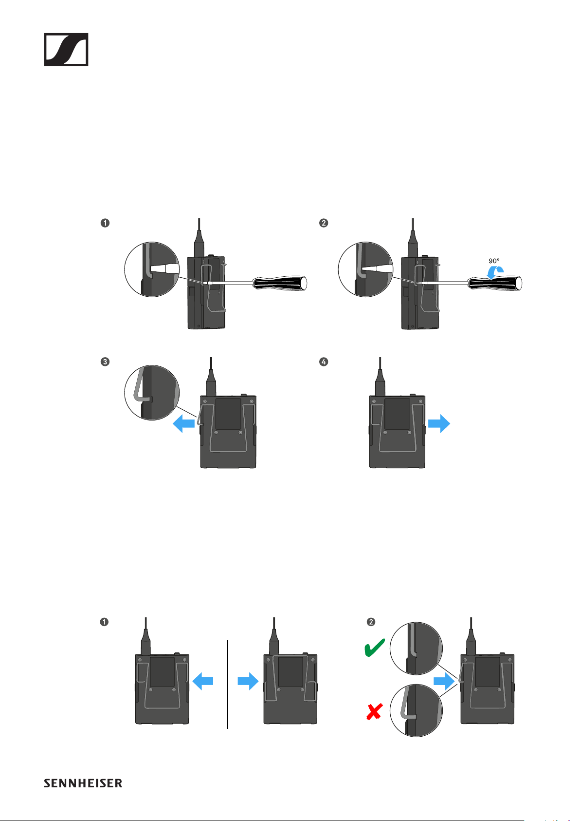
EW-DX SK | EW-DX SK 3-PIN bodypack transmitter
181
Changing the belt clip
You can change the belt clip on the bodypack transmitter or
flip it over depending on how you want to wear it.
To remove the belt clip:
▷Carefully loosen the belt clip with a small screwdriver as
shown in the figure.
▷Be very careful not to scratch the housing.
To insert the belt clip:
▷Insert one side of the belt clip first as shown in the figure.
▷Then insert the second side of the belt clip.
▷Gently press the belt clip all the way in on both sides.
▷Always insert one side before the other, not at the same
time, as otherwise the belt clip could bend.
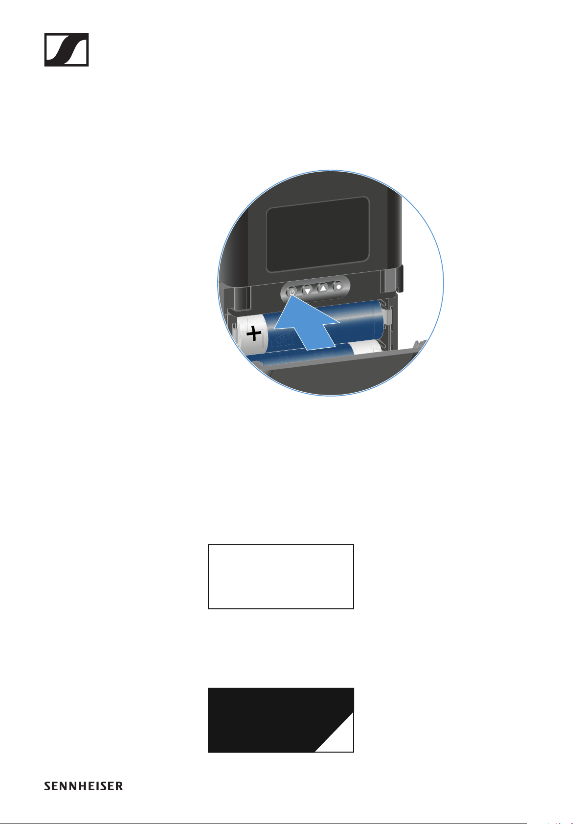
EW-DX SK | EW-DX SK 3-PIN bodypack transmitter
182
Switching the bodypack transmitter on and
off
To switch the bodypack transmitter on:
▷Short-press the ON/OFF button.
The LINK LED lights up and the transmitter switches on.
►
To switch the bodypack transmitter off:
▷Hold down the ON/OFF button until the LEDs switch off.
Note that the transmitter’s permanent E-Ink display still dis-
plays the parameters after it is switched off.
EW-DX 1
510.100
EW-DX 1
510.100
off
Display when transmitter is switched on:
Display when transmitter is switched off:
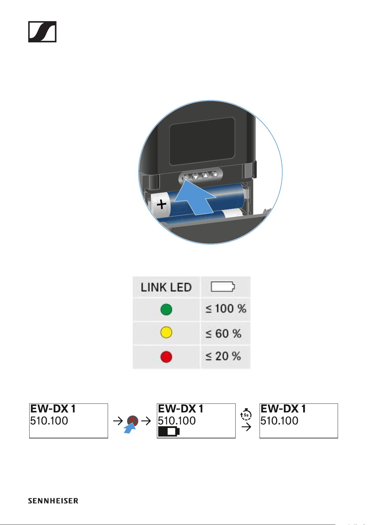
EW-DX SK | EW-DX SK 3-PIN bodypack transmitter
183
Checking the battery status of the transmit-
ter (Check function)
To check the battery status of the transmitter:
▷Short-press the ON/OFF button on the transmitter.
►
The transmitter’s LINK LED flashes to indicate the current
charge level of the battery or the BA 70 rechargeable battery.
►
In addition, the battery status is displayed on the transmitter
display for approx. 5 seconds.
►
Pressing the transmitter’s ON/OFF button will simultaneously
trigger the Identify function: "Identifying the paired receiver
(Identify function)".
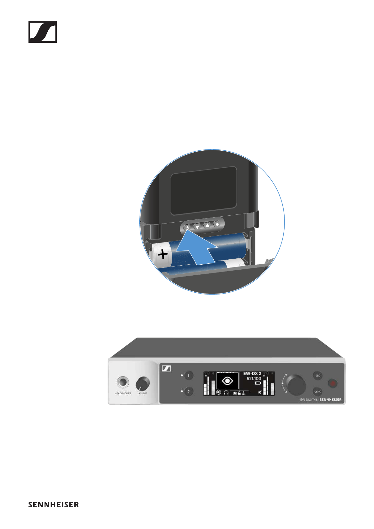
EW-DX SK | EW-DX SK 3-PIN bodypack transmitter
184
Identifying the paired receiver (Identify func-
tion)
In multi-channel systems, you can use the Check function to
quickly identify to which receiver the transmitter is paired.
Both the transmitter and receiver must be switched on.
▷Short-press the ON/OFF button on the transmitter.
►
An eye flashes next to the respective receiving channel on
the coupled receiver’s display.
►
Pressing the transmitter’s ON/OFF button will simultaneously
trigger the Check function: "Checking the battery status of the
transmitter (Check function)".
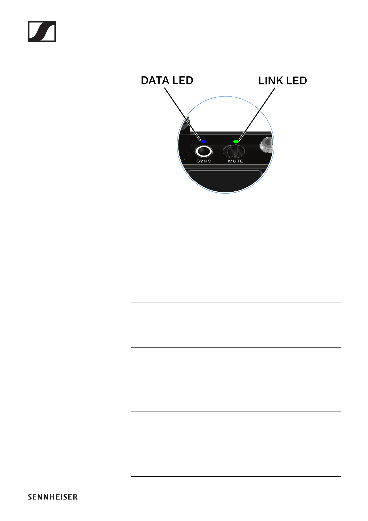
EW-DX SK | EW-DX SK 3-PIN bodypack transmitter
185
Meaning of the LEDs
The LINK and DATA LEDs on the top of the transmitter can in-
dicate the following information.
LINK LED
The LINK LED provides information about the status of the ra-
dio link between the transmitter and receiver, as well as status
information for the transmitter.
The LED is green:
▷The transmission frequency is active.
The LED is yellow:
▷The link between the transmitter and receiver is estab-
lished.
▷The audio signal is muted.
The LED is flashing yellow:
▷The link between the transmitter and receiver is estab-
lished.
▷The audio signal is overdriven (clipping).
EW-DX SK | EW-DX SK 3-PIN bodypack transmitter
186
The LED is continuously red:
▷The (rechargeable) battery in the transmitter is dead.
The LED is flashing red:
▷The link between the transmitter and receiver is estab-
lished.
▷The battery/rechargeable battery in the transmitter is low.
The LED is off:
▷No link between the transmitter and receiver.
▷The transmitter is switched off.
DATA LED
The DATA LED provides information about the synchroniza-
tion of transmitters and receivers.
The LED is flashing blue:
▷The transmitter is being synchronized with a receiver.
The LED is continuously blue:
▷The firmware is being updated.
The LED is off:
▷There is currently no active data link.

EW-DX SK | EW-DX SK 3-PIN bodypack transmitter
187
Establishing a connection to the receiver
To establish a radio link between the transmitter and the re-
ceiver, the two devices must be set to the same frequency.
See "Establishing a radio link | Synchronizing the receiver and
transmitter".
Conditions and restrictions for using frequencies
There may be special conditions and restrictions for using fre-
quencies in your country.
Before putting the product into operation, find the information
for your country at the following address:
www.sennheiser.com/sifa
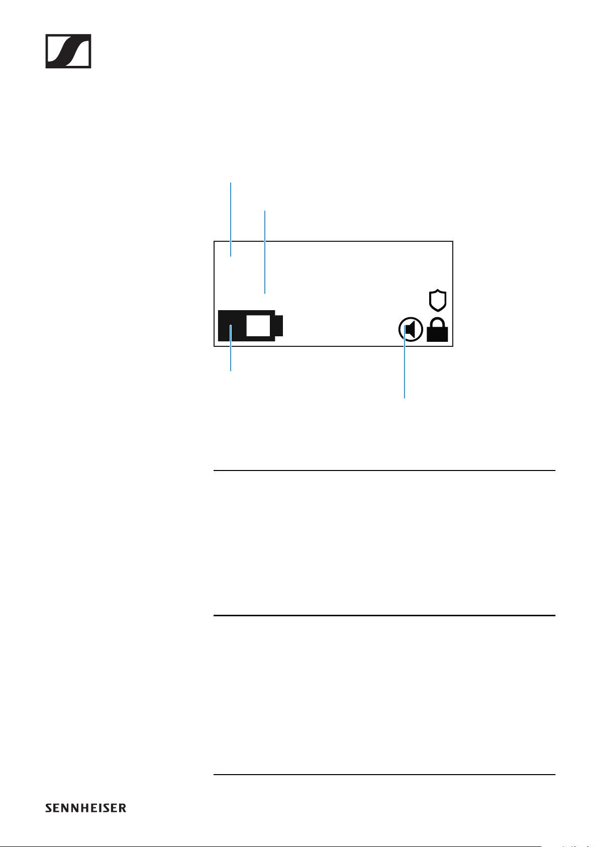
EW-DX SK | EW-DX SK 3-PIN bodypack transmitter
188
Information on the bodypack transmitter’s
display
You can view the following information on the transmitter dis-
play.
Further information
Link name:
You can assign a name to the radio link in the transmitter’s
menu (see "Name menu item").
Alternatively, you can assign the name in the receiver’s menu
and then synchronize it to the transmitter (see "Ch 1 / Ch 2 ->
Name menu item").
Frequency:
You can manually set the frequency of the radio link in the
transmitter’s menu (see "Frequency menu item").
The frequency of the radio link can also be set manually in the
receiver’s menu (see "Ch 1 / Ch 2 -> Frequency menu item") or
via the Auto Setup function (see "Ch 1 / Ch 2 -> Scan / Auto
Setup menu item") and then synchronized to the transmitter.
EW-DX 1
510.100
6:43
System
icons
Frequency
Link name
Battery status

EW-DX SK | EW-DX SK 3-PIN bodypack transmitter
189
Battery status:
Displays the charging status of the batteries or the BA 70 bat-
tery pack.
When using the BA 70 rechargeable battery, the remaining
runtime is also displayed in hours and minutes.
The battery status is hidden in the display’s default state.
Short-press the On/Off button on the transmitter (Check
function, see "Checking the battery status of the transmitter
(Check function)") to display the battery status for approx. 5
seconds.
System icons:
The transmitter’s mute switch is deactivated. See "Mute But-
ton menu item".
The Auto Lock function is activated. See "Auto Lock menu
item".
AES 256 encryption is enabled. See "System -> Encryption
menu item".

EW-DX SK | EW-DX SK 3-PIN bodypack transmitter
190
Note that the transmitter’s permanent E-Ink display still dis-
plays the parameters after it is switched off.
EW-DX 1
510.100
EW-DX 1
510.100
off
Display when transmitter is switched on:
Display when transmitter is switched off:
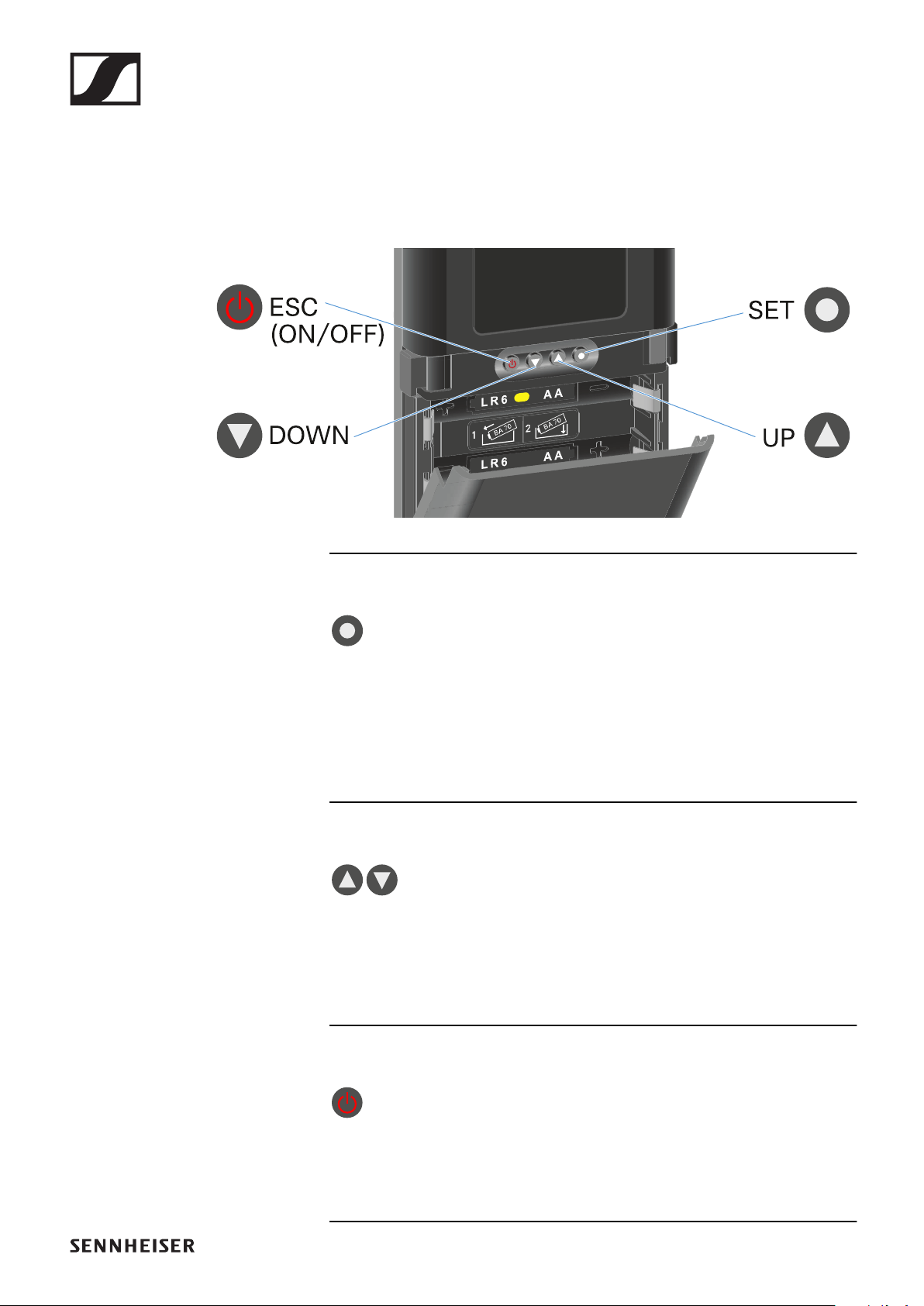
EW-DX SK | EW-DX SK 3-PIN bodypack transmitter
191
Buttons for navigating the menu of the
bodypack transmitter
Use the following buttons to navigate through the transmit-
ter’s operating menu.
►
Press the SET button
•Jumps from the home screen to the operating menu
•Calls up a menu item
•Saves settings
Press the UP or DOWN button
•Changes to the previous or next menu item
•Changes the setting of a menu item
Press the ESC (ON/OFF) button
•Cancels the entry and returns to the previous display

EW-DX SK | EW-DX SK 3-PIN bodypack transmitter
192
Making settings in the menu of the bodypack
transmitter
Navigating through the menu
To open the menu:
▷Press the SET button.
The operating menu is shown on the transmitter display
panel.
To open a menu item:
Press the UP or DOWN buttons to navigate through the in-
dividual menu items.
Press the SET button to open the selected menu item.
▷"Buttons for navigating the menu of the bodypack transmit-
ter"
Making changes in a menu item
After you open a menu item, you can make changes as follows:
▷Press the UP or DOWN buttons to set the displayed value.
▷Press the SET button to save the setting.
▷Press the ESC button to leave the menu item without sav-
ing the setting.
▷"Buttons for navigating the menu of the bodypack transmit-
ter"
Menu item overview
In the menu items, you can configure the settings below and
display information.
Name menu item
You can enter the name of the link in this
menu item.
▷Press the UP or DOWN buttons to select a character.
▷Press the SET button to go to the next position.

EW-DX SK | EW-DX SK 3-PIN bodypack transmitter
193
▷At the last position, press the SET button to save the se-
lected name.
If you enter a name for the radio link in the Name menu item
on the receiver and then synchronize the receiving channel
with the transmitter, the name entered in the transmitter is
overwritten with the name entered in the receiver.
Frequency menu item
In this menu item, you can set the trans-
mitter’s transmission frequency.
▷Press the UP or DOWN button to set the frequency’s MHz
range.
▷Press the SET button to confirm your selection.
▷Press the UP or DOWN button to set the frequency’s kHz
range.
▷Press the SET button to save the set frequency.
If you set a frequency for the channel using the Frequency
menu item on the receiver or via the Scan / Auto Setup func-
tion and then synchronize the receiving channel with the
transmitter, the frequency entered in the transmitter is over-
written by the frequency set in the receiver.
Low Cut menu item
In this menu item, you can adjust the
value for the low cut filter.
•Setting range: Off, 30 Hz, 60 Hz, 80 Hz, 100 Hz, 120 Hz
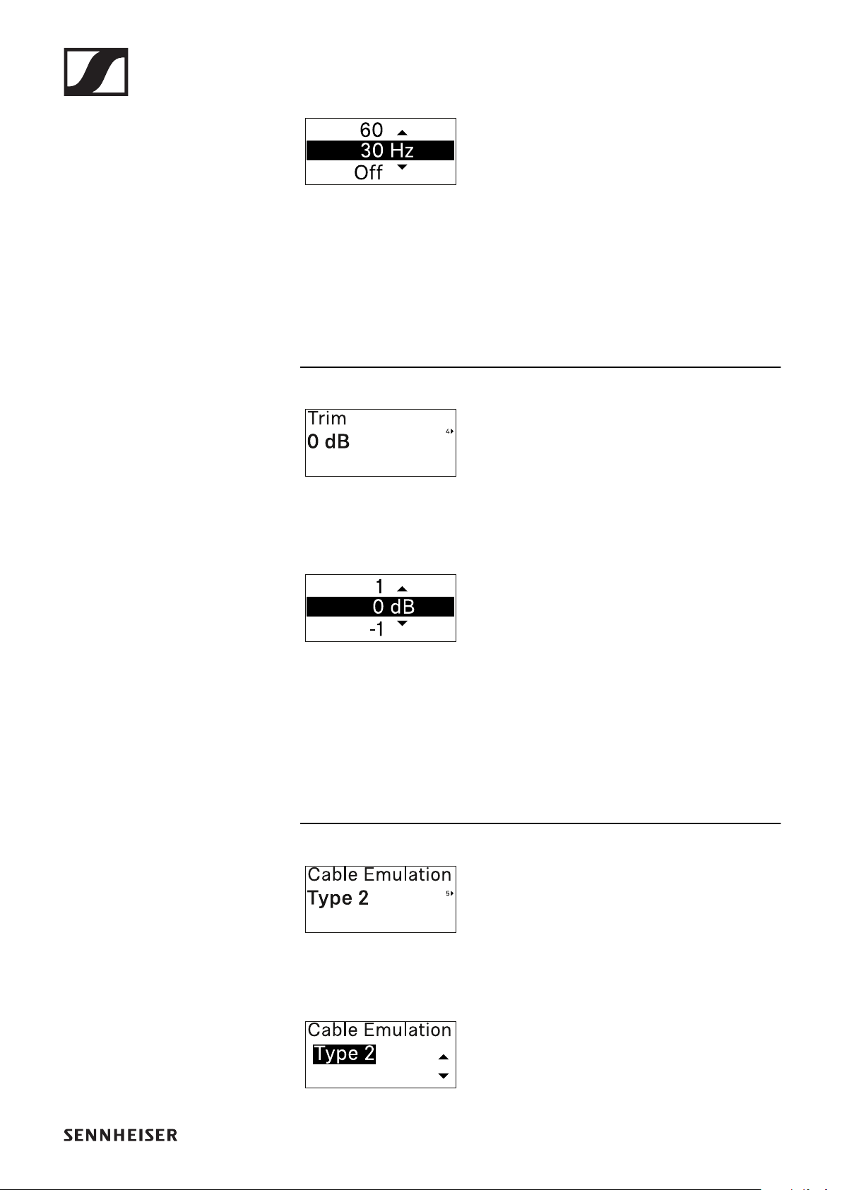
EW-DX SK | EW-DX SK 3-PIN bodypack transmitter
194
▷Press the UP or DOWN button to set the desired value.
▷Press the SET button to confirm your selection.
If you set a value for the channel’s low cut filter using the Low
Cut menu item on the receiver and then synchronize the re-
ceiving channel with the transmitter, the value entered in the
transmitter is overwritten by the value set in the receiver.
Trim menu item
In this menu item, you can adjust the au-
dio level of the transmitter as well as the
gain of the wireless link (can be set only
on the receiver) to suit input signals of different volumes.
•Setting range: -12 dB to +6 dB in increments of 1 dB
▷Press the UP or DOWN button to set the desired value.
▷Press the SET button to confirm your selection.
If you set a value for the channel in the Trim menu item on the
receiver and then synchronize the receiving channel with the
transmitter, the value entered in the transmitter is overwritten
with the value entered in the receiver.
Cable Emulation menu item
In this menu item, you can emulate in-
strument cable lengths.
•Setting range: Off, Type 1, Type 2, Type 3
▷Press the UP or DOWN button to set the desired value.

EW-DX SK | EW-DX SK 3-PIN bodypack transmitter
195
▷Press the SET button to confirm your selection.
If you set a value for the channel in the Cable Emul. menu item
on the receiver and then synchronize the receiving channel
with the transmitter, the value entered in the transmitter is
overwritten with the value entered in the receiver.
Test Tone menu item
In this menu item, you can activate a test
tone that the transmitter transmits in-
stead of the input signal. You can use
this feature to level out the system, for example.
•Setting range: Off, -90 dB to 0 dB in 6 dB increments
▷Press the UP or DOWN button to set the desired value.
▷Press the SET button to confirm your selection.
Mute Button menu item
In this menu item you can set the func-
tion of the transmitter’s mute switch.
•Setting range:
•Disabled: The mute switch has no function.
•RF Mute: The RF signal is deactivated when the mute
switch is on.
•AF Mute: The audio signal is muted when the mute switch
is on.
▷Press the UP or DOWN button to set the desired value.
▷Press the SET button to confirm your selection.
If you set a function for the transmitter’s mute switch in the
Mute Mode menu item on the receiver and then synchronize
the receiving channel with the transmitter, the value entered
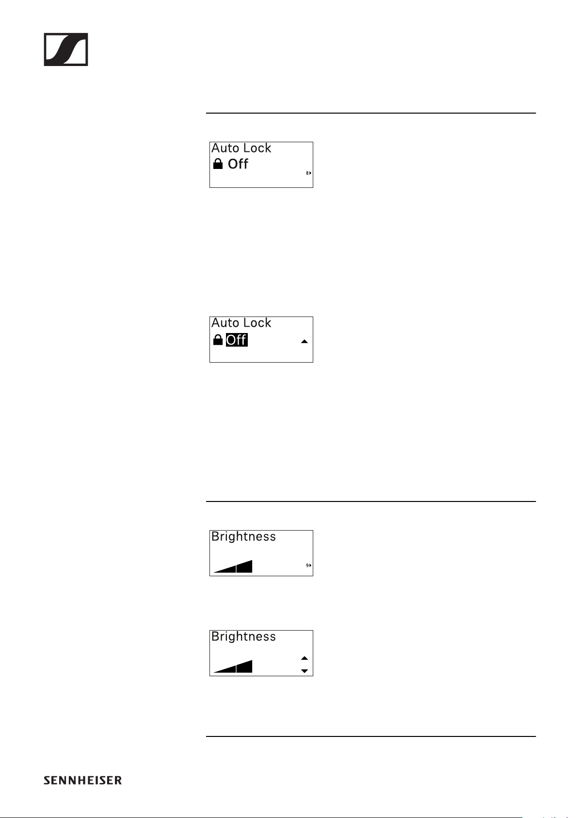
EW-DX SK | EW-DX SK 3-PIN bodypack transmitter
196
in the transmitter is overwritten with the value entered in the
receiver.
Auto Lock menu item
In this menu item, you can activate or
deactivate the automatic lock-off for the
transmitter.
The lock-off prevents the transmitter from being unintention-
ally switched off and also prevents any changes to the trans-
mitter’s menu.
If you want to change settings in the transmitter’s menu while
the lock-off is active, you have to temporarily disable the lock-
off. See .
▷Press the UP or DOWN button to set the desired value.
▷Press the SET button to confirm your selection.
If you set a value for the transmitter’s automatic lock-off in the
Auto Lock menu item on the receiver and then synchronize
the receiving channel with the transmitter, the value entered
in the transmitter is overwritten with the value entered in the
receiver.
Brightness menu item
In this menu item, you can adjust the
brightness of the transmitter’s display.
You can turn off the backlight complete-
ly or set it to one of five brightness levels.
▷Press the UP or DOWN button to set the desired value.
▷Press the SET button to confirm your selection.
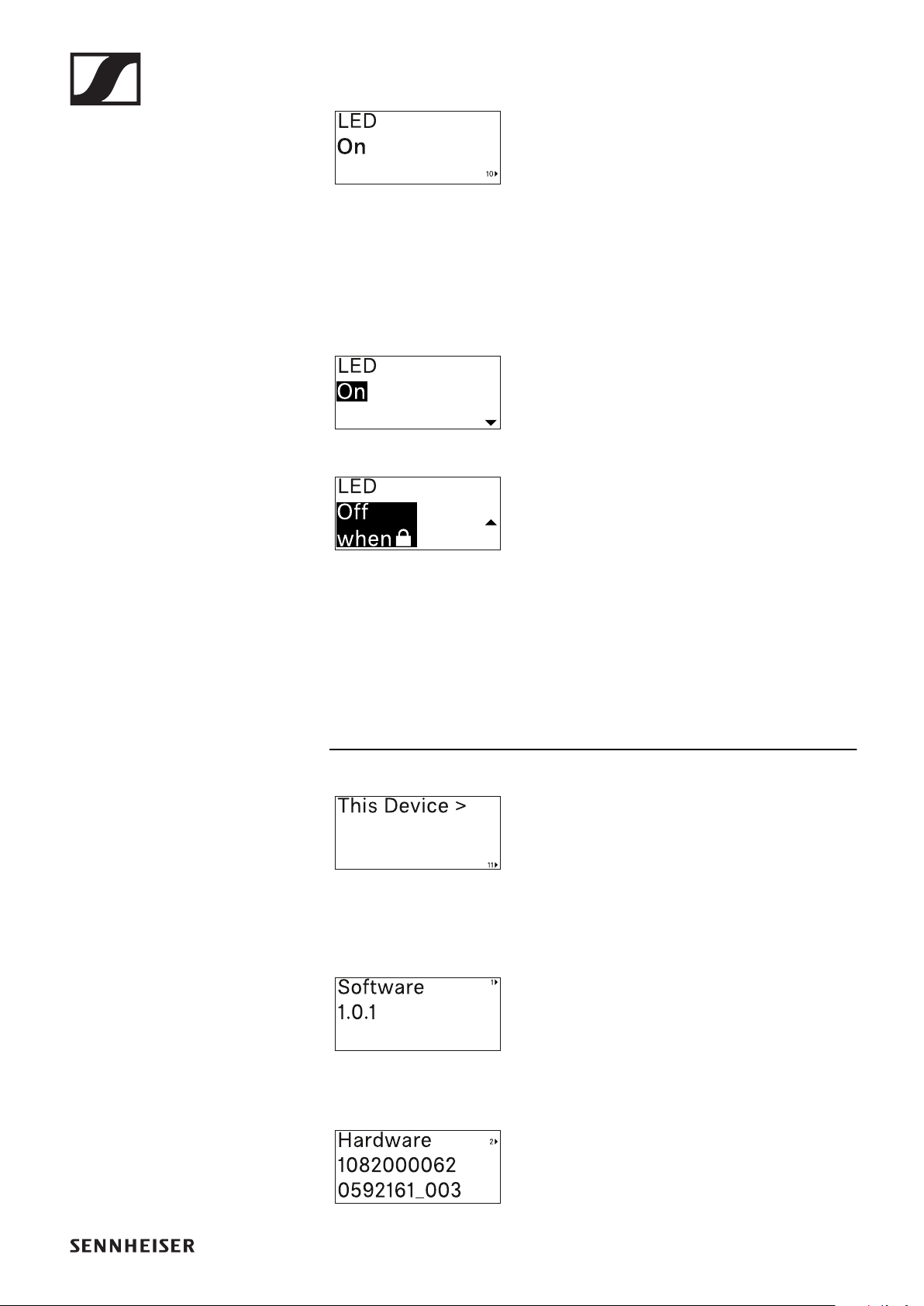
EW-DX SK | EW-DX SK 3-PIN bodypack transmitter
197
LED menu item
This menu item allows you to set the be-
havior of the transmitter’s LINK LED.
•Setting range:
•ON: The LINK LED remains continuously lit.
•OFF: The LINK LED switches off while the lock-off func-
tion is active.
▷Press the UP or DOWN button to set the desired value.
▷Press the SET button to confirm your selection.
If you set a function for the transmitter’s LINK LED in the LED
menu item on the receiver and then synchronize the receiving
channel with the transmitter, the value entered in the trans-
mitter is overwritten with the value entered in the receiver.
This Device menu item
In this menu item you can view informa-
tion about the transmitter’s software
and hardware and reset the transmitter
to the factory settings.
Show software
Show hardware
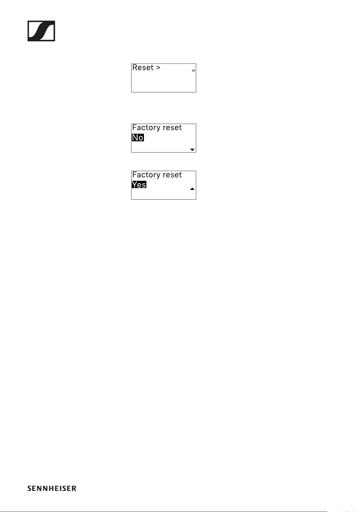
EW-DX SK | EW-DX SK 3-PIN bodypack transmitter
198
Reset to factory settings
▷Press the SET button to open the Reset menu item.
▷Press the UP or DOWN button to set the desired value.
▷Press the SET button to confirm your selection.
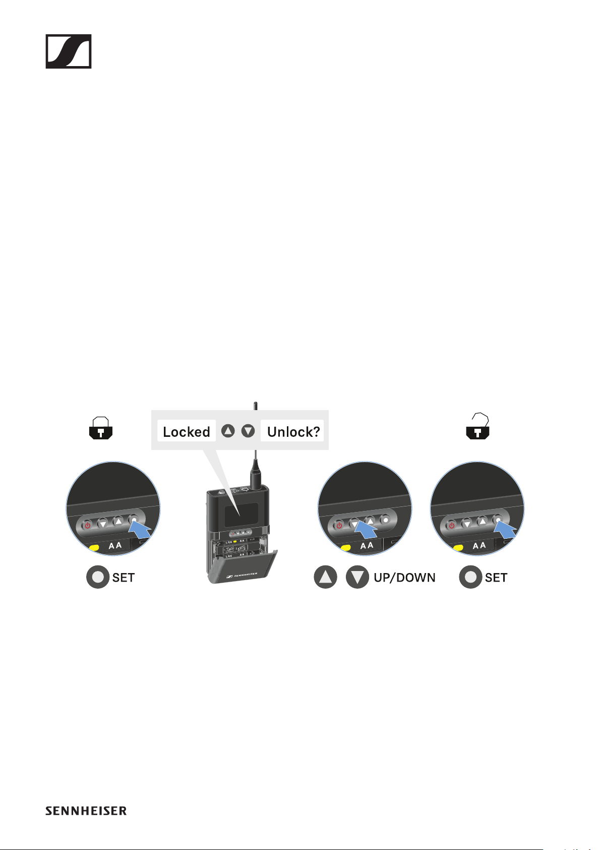
EW-DX SK | EW-DX SK 3-PIN bodypack transmitter
199
Lock-off function
You can enable or disable the automatic lock-off function in
the Auto Lock menu item (see "Auto Lock menu item").
The lock-off function prevents the transmitter from being un-
intentionally switched off and also prevents any unintentional
changes to the transmitter’s configuration.
If you have enabled the Auto Lock function, you will have to
temporarily deactivate the lock-off function to operate the
transmitter.
To temporarily deactivate the lock-off function:
▷Press the SET button.
Locked appears in the display panel.
▷Press the UP or DOWN button.
Unlock? appears in the display panel.
▷Press the SET button.
Lock-off function is now temporarily deactivated.
The lock-off function remains deactivated while you are ac-
tively working in the operating menu.
After 10 seconds of inactivity, it automatically activates again.

EW-DX SK | EW-DX SK 3-PIN bodypack transmitter
200
Configuring mute mode and muting the
bodypack transmitter
You can mute the bodypack transmitter by using the mute
switch to turn off either the audio signal (AF Mute) or the RF
signal (RF Mute).
To do this, you must configure the function of the mute switch
in the Mute Mode menu item.
▷On the receiver: "Ch 1 / Ch 2 -> Mute Mode menu item"
▷ON the transmitter: "Mute Button menu item"
AF Mute
▷Slide the mute switch to the desired position to mute or ac-
tivate the audio signal.
RF Mute
▷Slide the mute switch to the desired position to activate or
deactivate the RF signal.
Updating the firmware of the transmitter
The transmitter firmware is updated via the receiver.
▷Update the transmitter firmware using the TX Update
menu item in the receiver’s System menu. See "System ->
TX Update menu item".
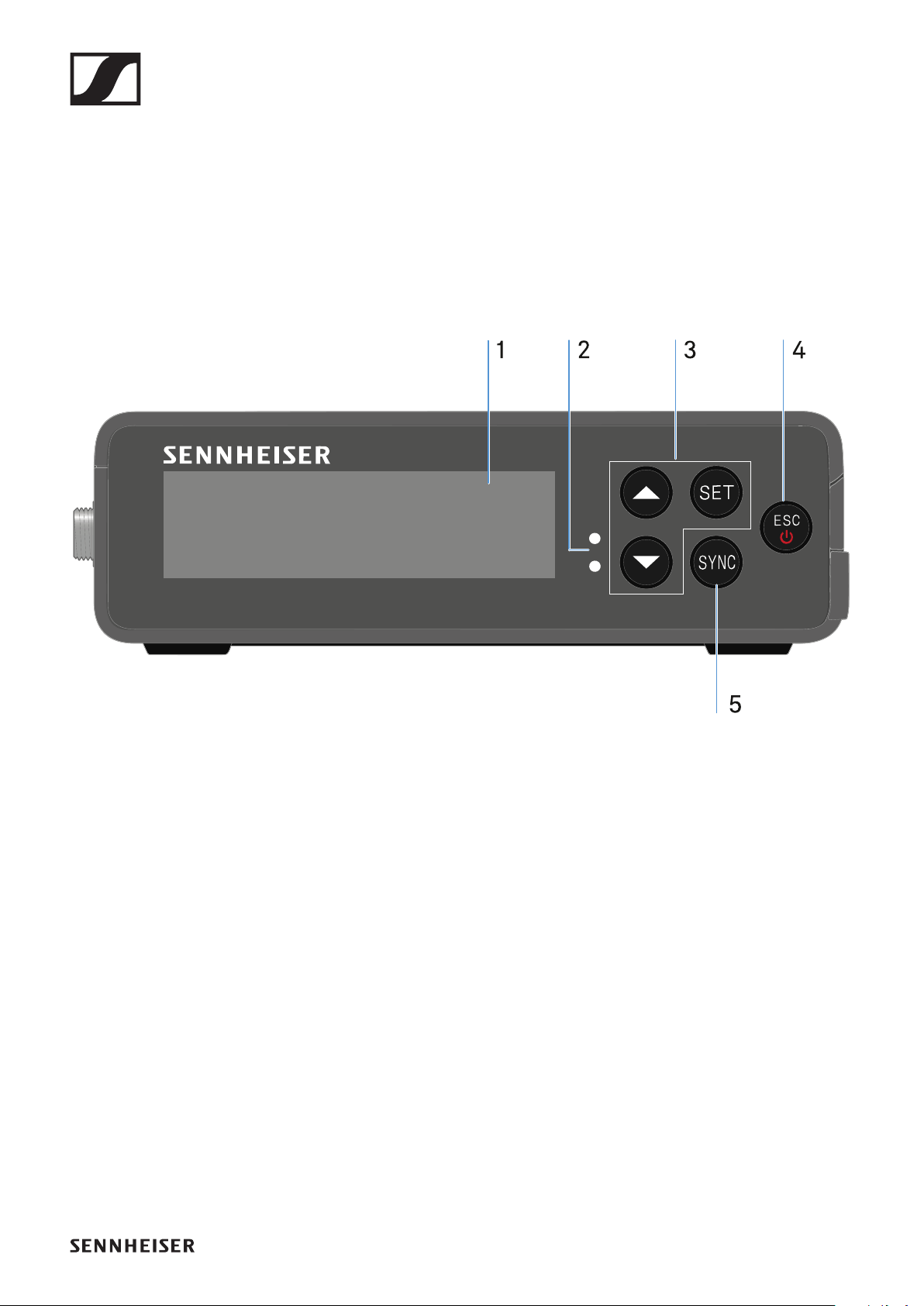
EW-DP EK portable receiver
201
EW-DP EK portable receiver
Product overview
Front
1Display for status information and operating menu
•See "Displays on the receiver’s display panel"
2LINK and DATA LEDs to indicate connection status and
Bluetooth status
•See "Meaning of the LEDs"
3UP/DOWN/SET menu buttons for navigating the operating
menu
•See "Making settings in the menu"
4ESC/ON/OFF button for canceling an action in the menu or
switching the device on and off
•See "Making settings in the menu"
•See "Switching the receiver on and off"
5SYNC button for synchronizing the transmitter and receiver
•See "Establishing a radio link | Synchronizing the receiver
and transmitter"
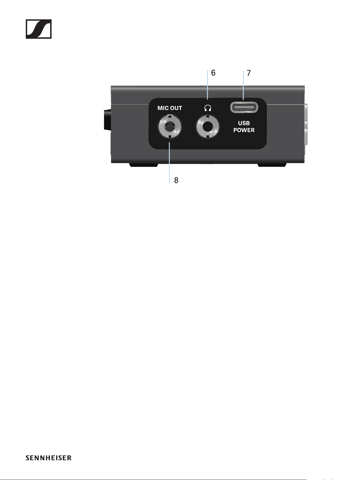
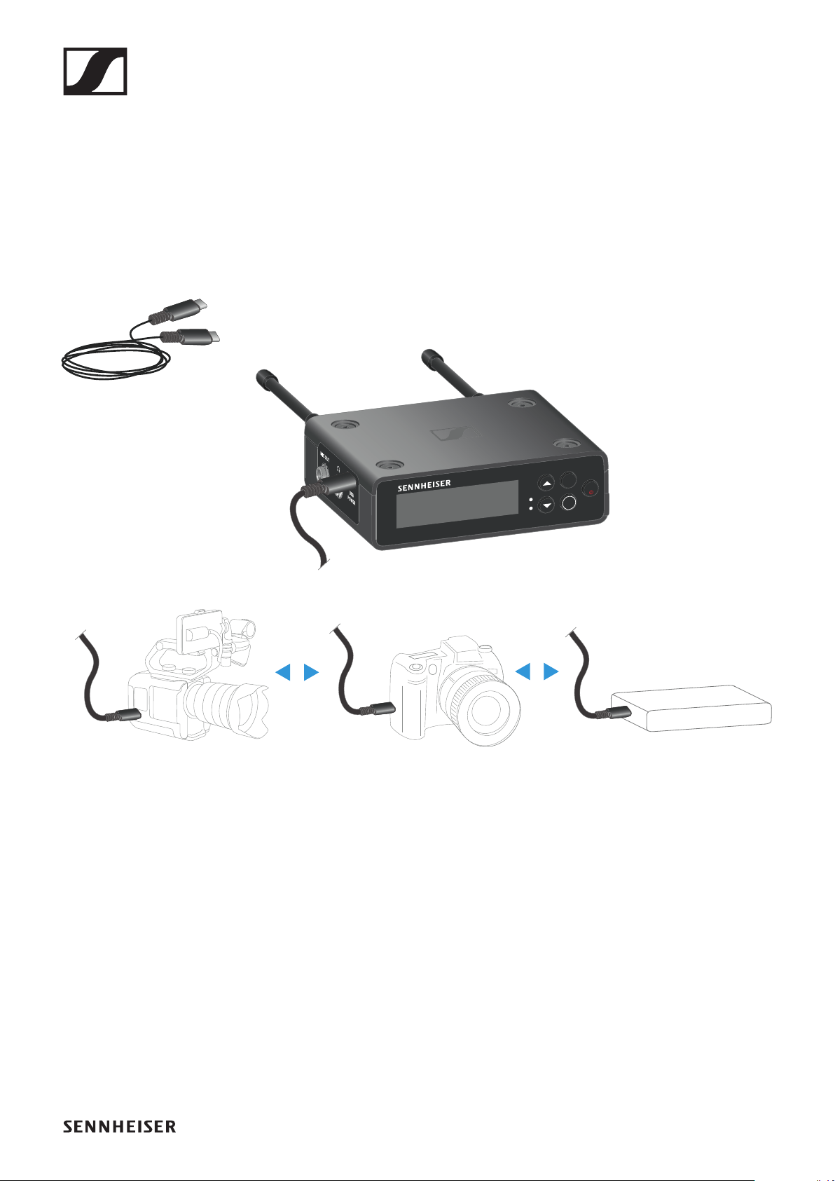
EW-DP EK portable receiver
203
Power supply
The EW-DP EK can be powered in two different ways:
Power supply via USB-C from a camera or power
bank:
▷Connect the receiver to a camera or other power supply us-
ing a USB-C cable.
Power supply via USB-C cable: 5 V/min. 1 A (for max.
charging speed of the inserted BA 70)
ESC
SYNC
SET
USB-C Power
Powerbank
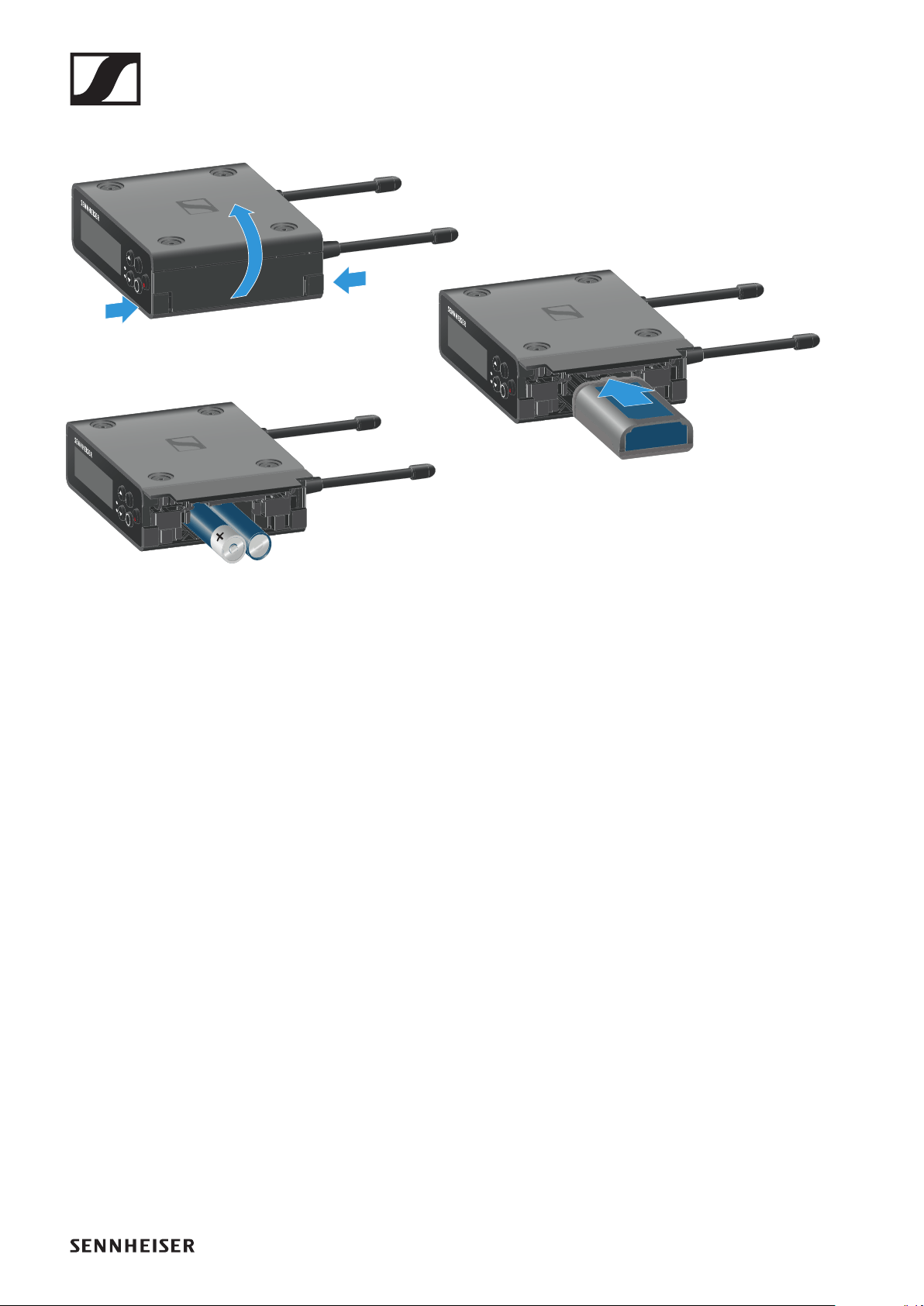
EW-DP EK portable receiver
204
Power supply via (rechargeable) batteries:
▷Open the EW-DP EK unit’s battery compartment by press-
ing in the two release buttons on the sides.
▷Insert either a BA 70 rechargeable battery or 2 AA batter-
ies.
▷Close the battery compartment.
Primary batteries and USB can be used in parallel without
restrictions, as this is controlled by the EK unit.
The EW-DP EK supports the USB Power Delivery Protocol
for smart USB-C power supply units (USB-C PD).
ESC
SYNC
SET
ESC
SYNC
SET
ESC
SYNC
SET
optional:
2 AA batteries
BA 70 rechargeable battery
(included in scope of delivery)

EW-DP EK portable receiver
205
Outputting audio signals
The EW-DP EK has an unbalanced 3.5 mm audio output and an
unbalanced 3.5 mm headphone output.
CAUTION
Danger due to high volume levels
Volume levels that are too high may damage your hearing.
▷Turn down the volume of the headphone output before you
put on the headphone. Recommended impedance for head-
phones (HD 25 = 70 ohms). For headphones with < 32 ohms
of impedance, the audio signal can be very loud at the low-
est volume setting.
To connect a 3.5 mm jack cable:
▷Plug the jack cable into the MIC OUT socket on the EW-DP
EK.
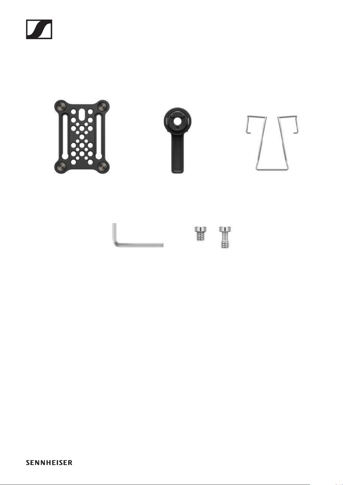
EW-DP EK portable receiver
206
Mounting the receiver / mounting options
EW-DP EK mounting accessories:
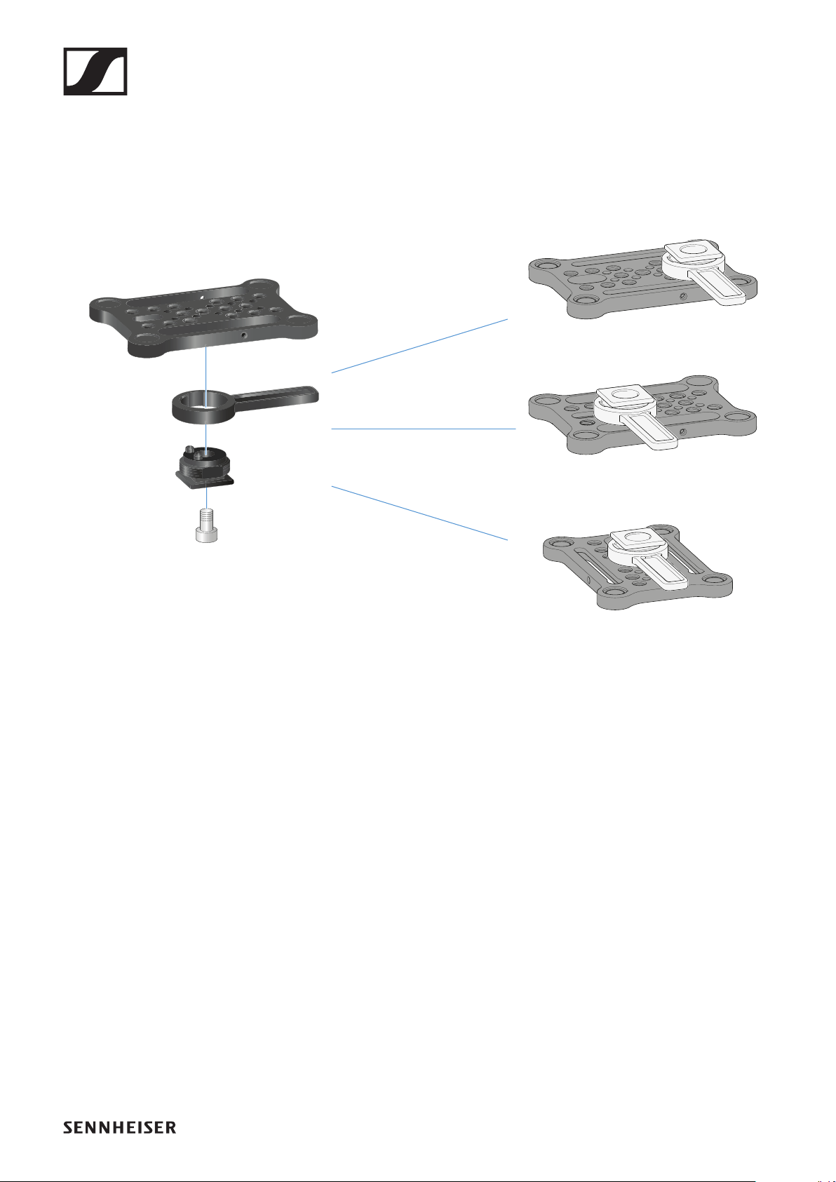
EW-DP EK portable receiver
207
Combining the mounting plate and hot shoe adapt-
er:
The hot shoe adapter can be fitted to the mounting plate in dif-
ferent positions according to the mounting situation.
To mount the hot shoe adapter on the mounting plate:
▷Pre-assemble the hot shoe adapter by connecting the
adapter and lever using the supplied screw.
▷Then screw the hot shoe adapter to the mounting plate at
the desired location.
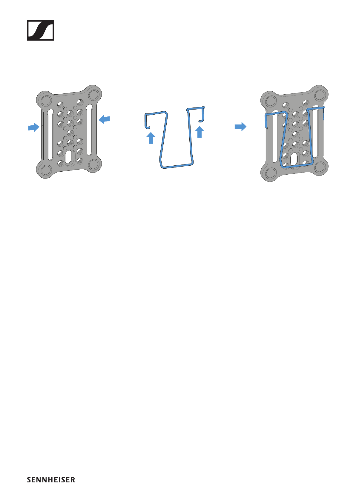
EW-DP EK portable receiver
208
Mounting plate and clip:
As an alternative to the hot shoe adapter, a metal clip can be
attached to the side of the mounting plate.
To mount the clip on the mounting plate:
▷Insert the clip into the side of the mounting plate as shown.
This enables you to attach the receiver to belts or pockets
using the mounting plate.
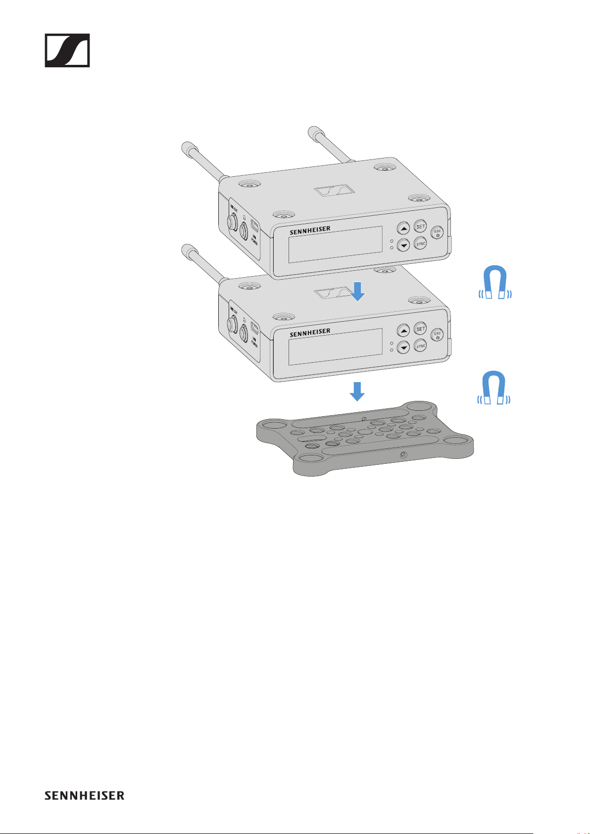
EW-DP EK portable receiver
209
Mounting/stacking receivers on the mounting plate:
The receiver has magnets on the bottom, which means you
can simply place it on the mounting plate without the need for
an additional screw connection. This allows you to stack two
receivers on top of one another.
To mount the receiver on the mounting plate:
▷Insert the receiver’s four magnetic feet into the recesses on
the mounting plate.
Two stacked receivers can be connected to one another us-
ing a Y-cable. See "Cables for EW-DP EK"
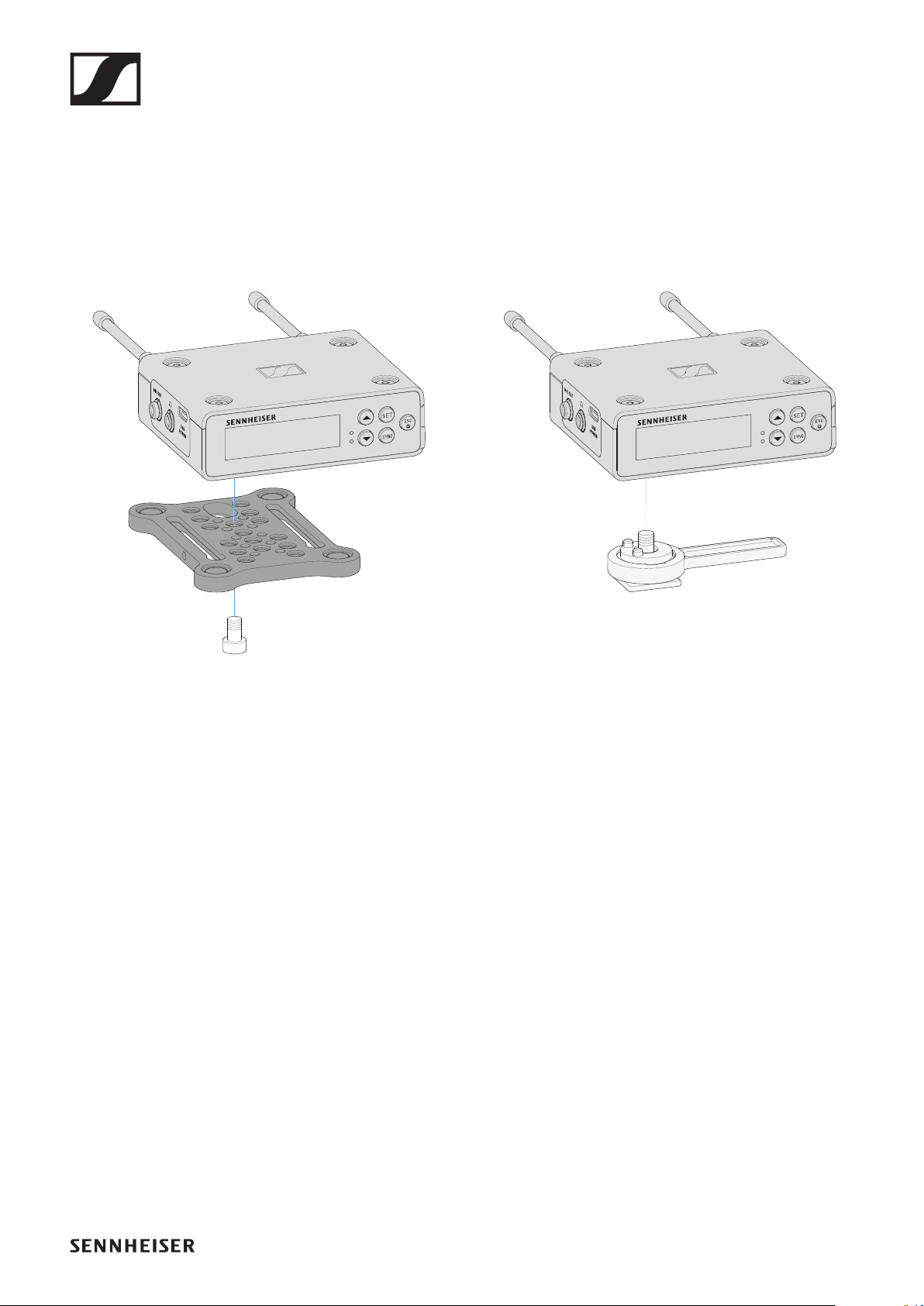
EW-DP EK portable receiver
210
Mounting with the mounting plate in a rotated posi-
tion:
To mount the receiver with the mounting plate rotated by 90°:
▷Turn the mounting plate by 90° and screw it to the bottom
of the receiver in the desired position.
This mounting variant is particularly suitable for attaching
with a clip.
To mount the receiver without a mounting plate:
▷Screw the hot shoe adapter directly to the bottom of the re-
ceiver.
It can now be attached to a camera’s hot shoe.
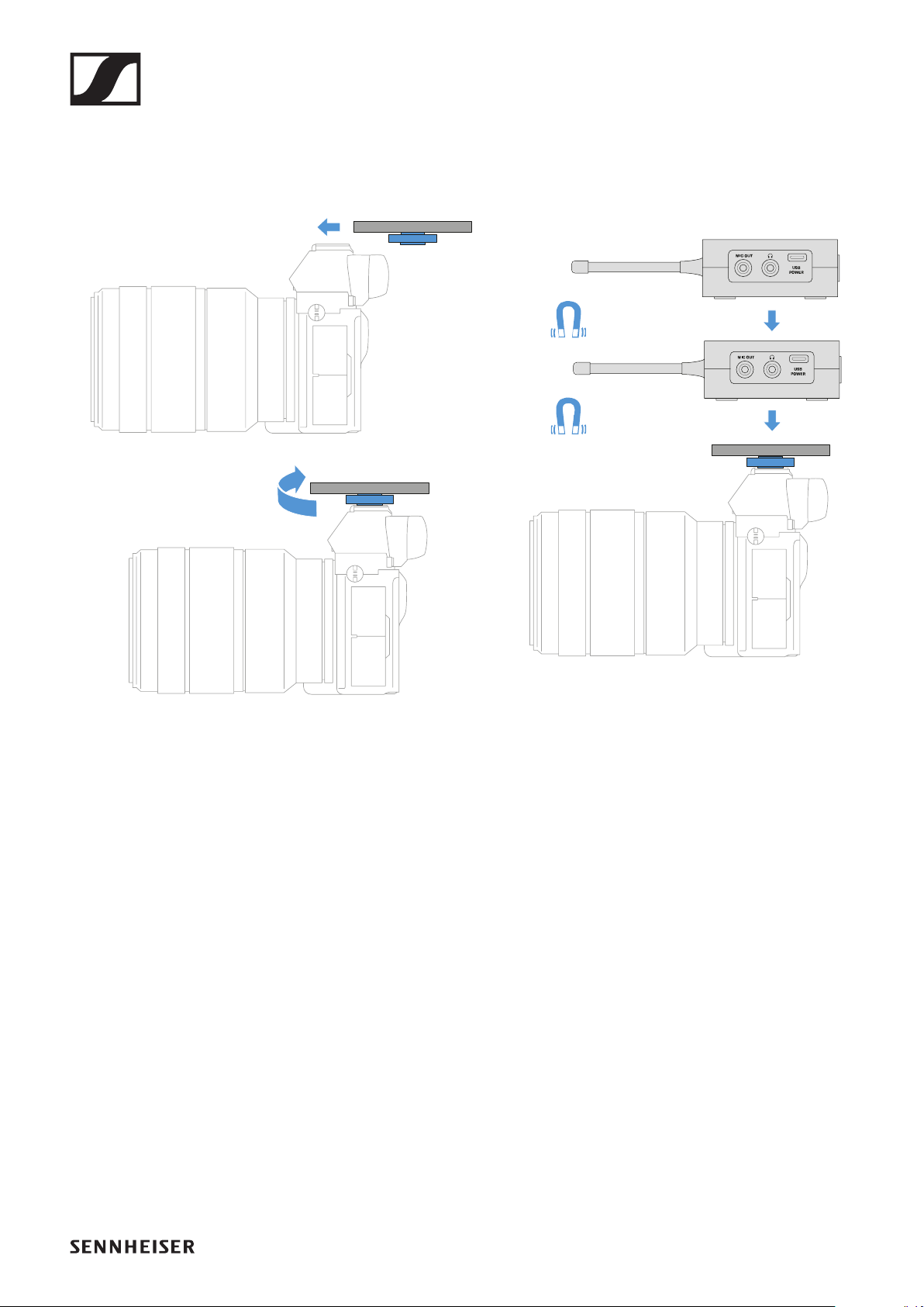
EW-DP EK portable receiver
211
Example for mounting on a DSLR or video camera:
To mount the mounting plate with hot shoe adapter on a DSLR
or video camera
:
▷Slide the adapter into the camera’s hot shoe.
▷Rotate the lever on the hot shoe adapter until the adapter is
tightly attached.
Now you can attach one or two receivers to the mounting
plate.

EW-DP EK portable receiver
212
Example for mounting on camera cages:
To attach the mounting plate to a camera cage:
▷Screw the mounting plate to the camera cage using one or
two screws, depending on the mounting situation and posi-
tion.
▷Attach the receiver to the mounting plate.
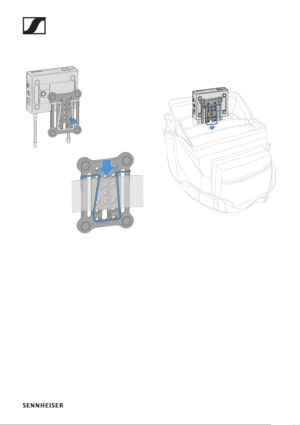
EW-DP EK portable receiver
213
Example for attaching to pockets and belts:
To fasten the receiver with mounting plate to pockets or belts:
▷Attach the clip to the mounting plate.
▷Attach the mounting plate to the receiver by inserting a
screw through the slot.
You can now clip the receiver to belts or pockets.
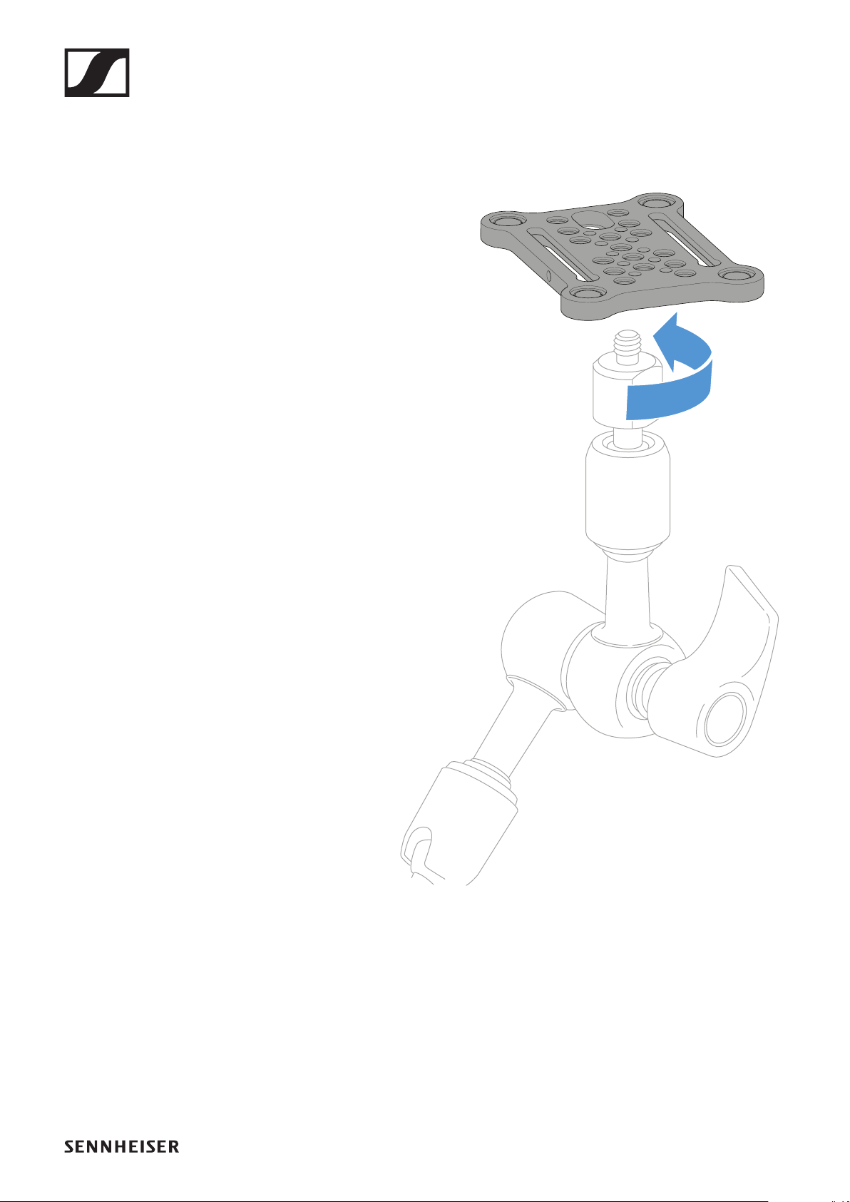
EW-DP EK portable receiver
214
Example for mounting on tripods:
To fasten the mounting plate to a tripod:
▷Screw the mounting plate onto the tripod thread at the de-
sired position.
Now you can attach one or two receivers to the mounting
plate.
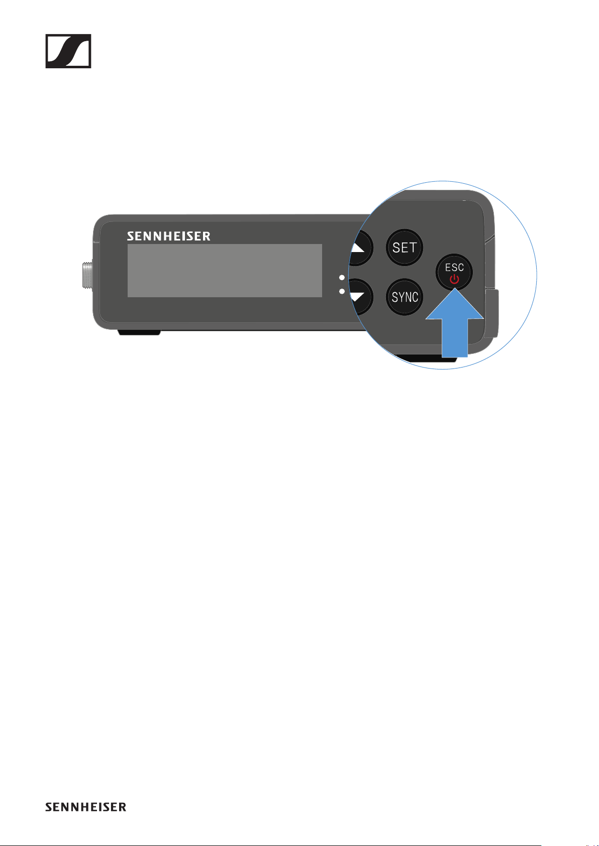
EW-DP EK portable receiver
215
Switching the receiver on and off
To switch the receiver
on:
▷Short-press the ON/OFF button.
The receiver switches on.
To switch the receiver
off:
▷Press the ON/OFF button.
▷The receiver switches off.
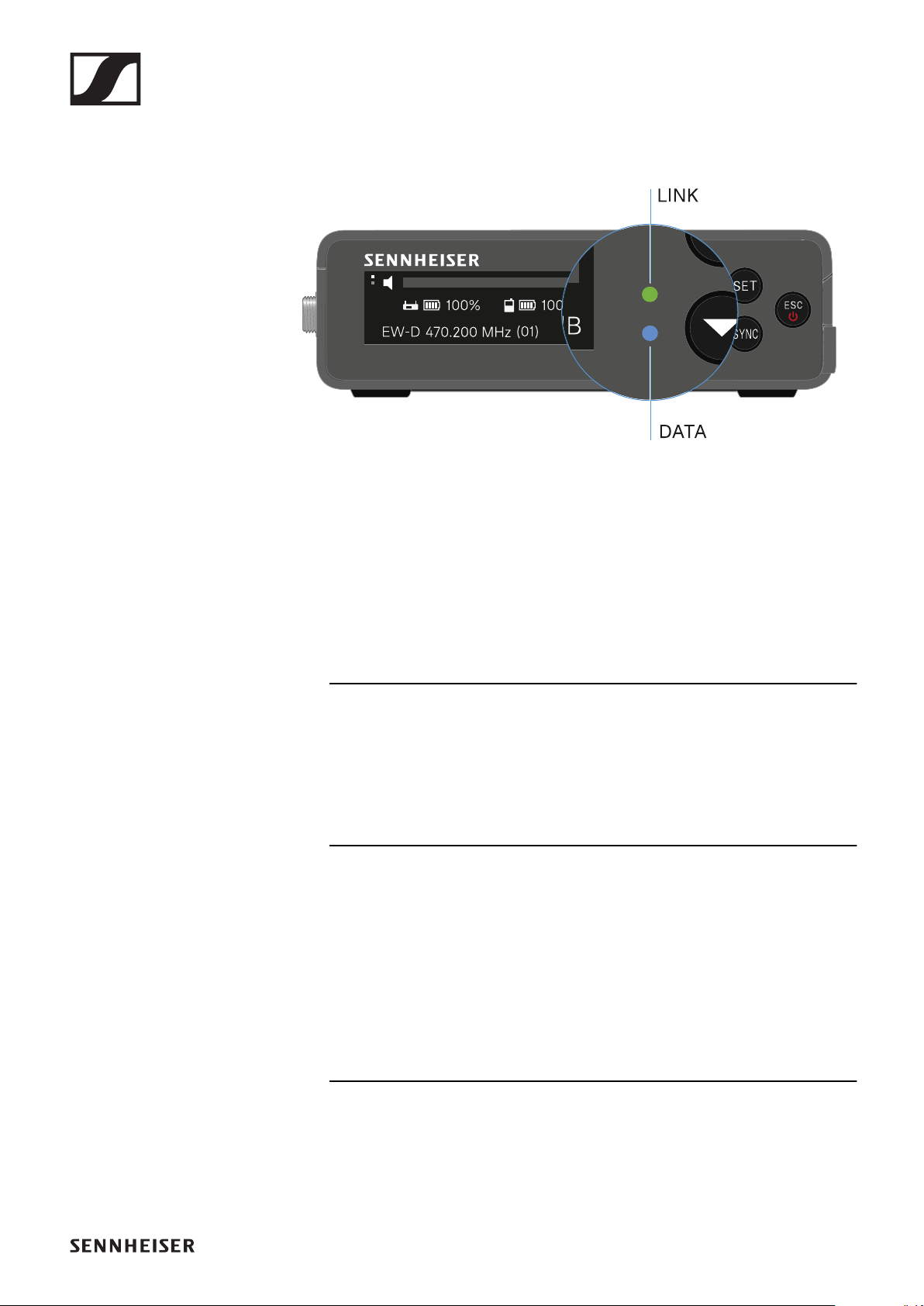
EW-DP EK portable receiver
216
Meaning of the LEDs
The LINK and DATA LEDs on the front of the receiver can in-
dicate the following information.
LINK LED
The LINK LED provides information about the status of the ra-
dio link between the transmitter and receiver, as well as status
information for the paired transmitter.
The LED is green:
▷The link between the transmitter and receiver is estab-
lished.
▷The audio signal is active.
The LED is yellow:
▷The link between the transmitter and receiver is estab-
lished.
▷The audio signal is muted.
or
▷No microphone module is mounted on the SKM-S handheld
transmitter.
The LED is flashing yellow:
▷The link between the transmitter and receiver is estab-
lished.
▷The audio signal is overdriven (clipping).

EW-DP EK portable receiver
217
The LED is continuously red:
▷No link between the transmitter and receiver.
The LED is flashing red:
▷The battery/rechargeable battery in the paired transmitter
is low.
DATA LED
The DATA LED provides information on the receiver’s Blue-
tooth Low Energy link to the EW-D Smart Assist app and on
the synchronization of transmitters and receivers.
The LED is flashing blue:
▷The Bluetooth Low Energy link is being established be-
tween the receiver and a smartphone or tablet with the
EW-D Smart Assist app.
or
▷The receiver is being synchronized with a transmitter.
The LED is continuously blue:
▷The firmware is being updated.
The LED is off:
▷Normal operation
▷There is currently no active data link.
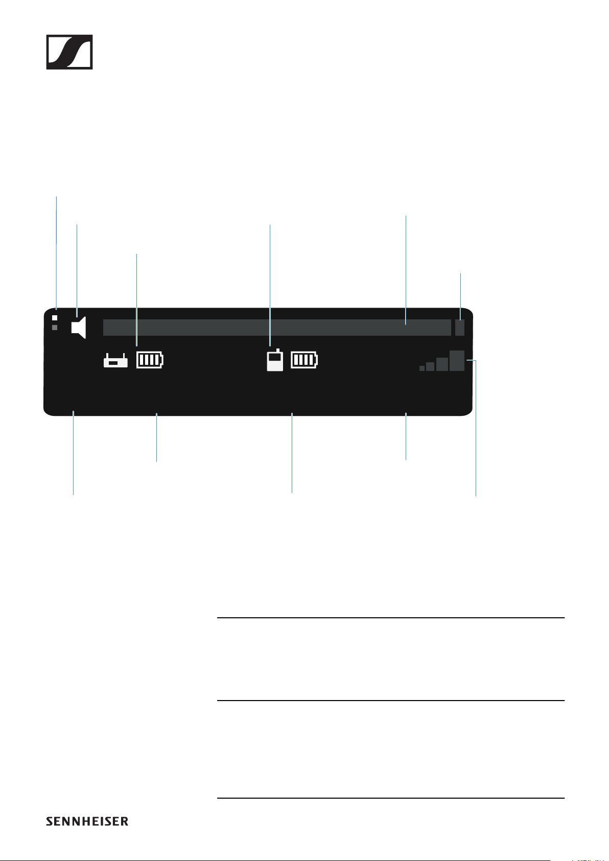
EW-DP EK portable receiver
218
Displays on the receiver’s display panel
Status information such as frequency, reception quality, bat-
tery status and audio level is shown on the display.
The display also shows the operating menu, which you can use
to configure all of the settings (see "Making settings in the
menu").
Further information
Display page:
"Main view and advanced view"
Mute / mute switch:
"MUTE switch menu item" | "Muting the handheld transmitter"
| "Muting the bodypack transmitter"
EW-D
(01)
470.200 MHz
7:30h 12:00h
+18 dB
Channel
Transmitter
audio level
Gain
Transmitter
battery
(SK / SKM-S)
Frequency
Mute switch
Receiver
battery (EK)
Display page
Radio
frequency
level
Link name
PEAK
display

EW-DP EK portable receiver
219
Link name:
Can be changed in the Smart Assist app.
Receiver battery:
"Power supply"
Transmitter battery:
SKM-S -> "Inserting and removing the batteries/rechargeable
batteries" | SK -> "Inserting and removing the batteries/re-
chargeable batteries"
Frequency / channel:
"AUTO SCAN menu item" | "CHANNEL menu item"
Gain / transmitter audio level / PEAK indicator:
"GAIN menu item"
Radio frequency level:
"Establishing a radio link | Synchronizing the receiver and
transmitter"
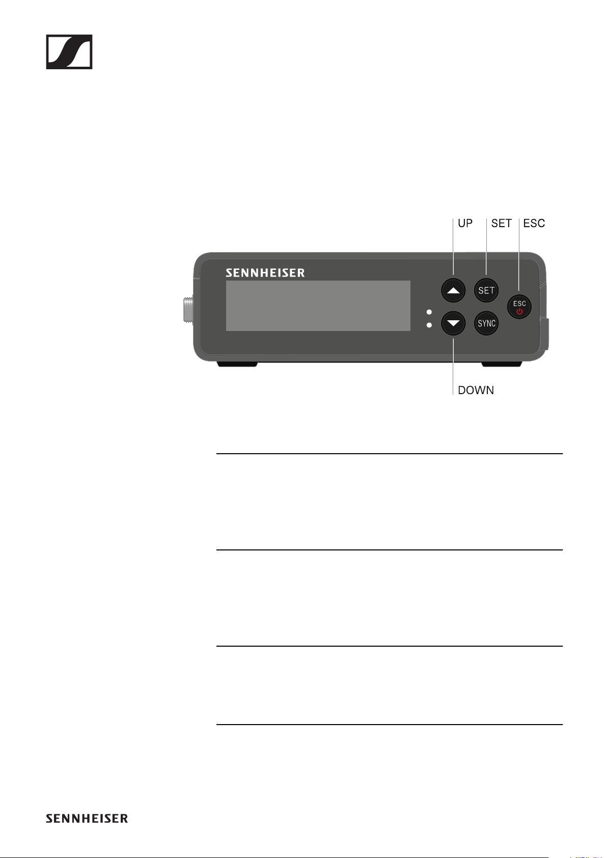
EW-DP EK portable receiver
220
Making settings in the menu
Buttons for navigating the menu
Use the following buttons to navigate through the receiver’s
operating menu.
►
Press the SET button
•Open the menu
•Save settings in a menu item
Press the UP or DOWN button
•Changes to the previous or next menu item
•Changes the setting of a menu item
Press the ESC button
•Cancel input
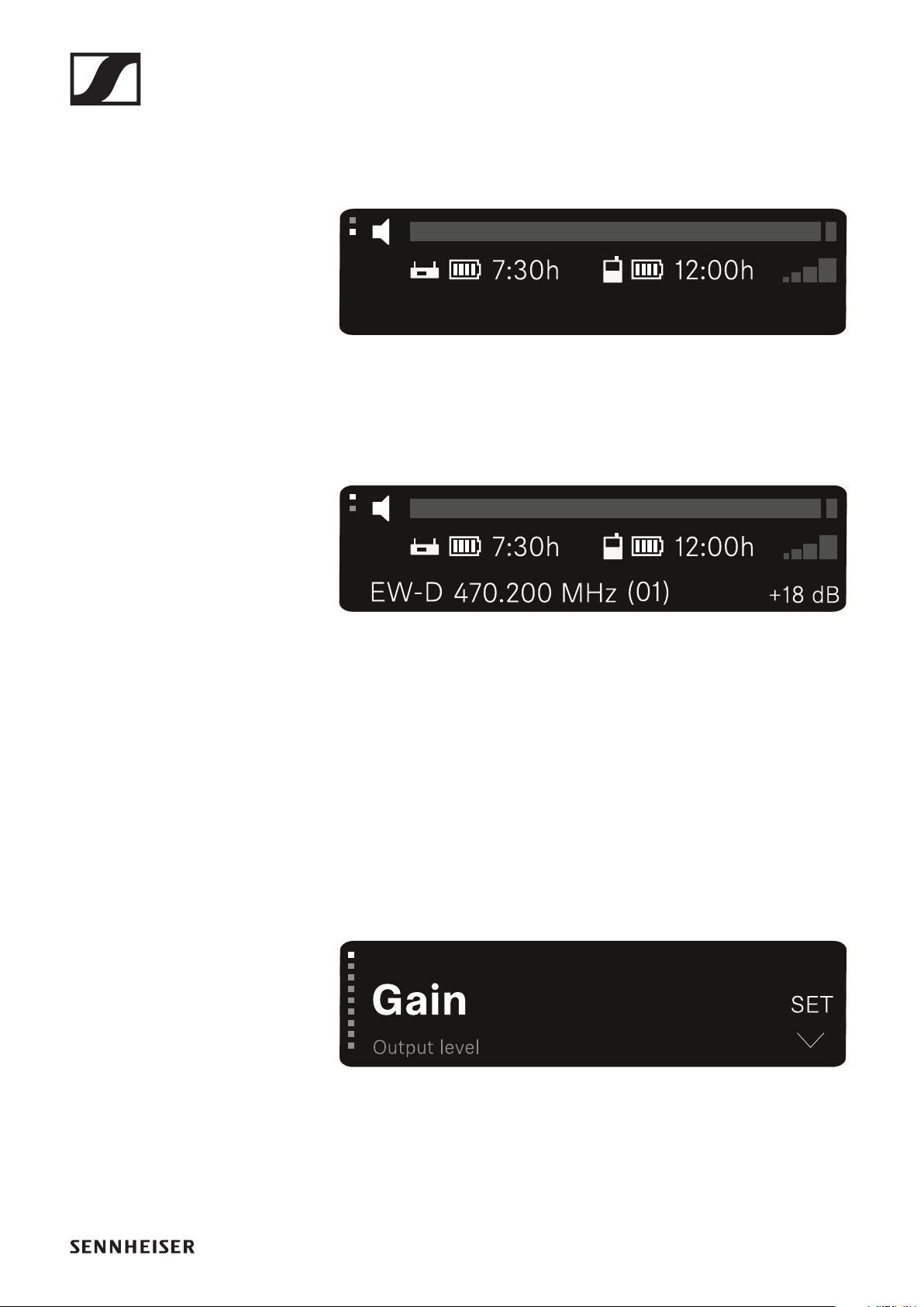
EW-DP EK portable receiver
221
Main view and advanced view
After the device switches on, the display shows the main
view.
►
See "Displays on the receiver’s display panel"
▷Press the UP button to access the advanced view.
►
See "Displays on the receiver’s display panel"
Opening the menu and navigating the menu items
To open the main menu:
▷Press the SET button.
The first menu item GAIN appears in the display.
►
To navigate the menu items:
▷Press the UP and DOWN buttons.
The currently active menu item appears in the display.
►
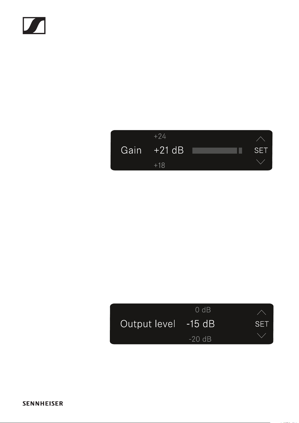
EW-DP EK portable receiver
222
To open a menu item:
▷Navigate to the desired menu item until it flashes.
▷Press the SET button to open the selected menu item.
GAIN menu item
Under the GAIN menu item, you can set the level of the audio
signal coming from the paired transmitter.
▷Open the GAIN menu item.
The display looks as follows.
►
▷Press the UP or DOWN button to adjust the value.
▷Press the SET button to save the set value. You will then be
returned to the main view or advanced view.
Output level menu item
Under the Output level menu item, you can set the level of the
audio signal coming from the receiver’s audio outputs. This
audio signal can be output to a camera input or a mixing con-
sole, for example.
▷Open the Output level menu item.
The display looks as follows.
►
▷Press the UP or DOWN button to adjust the value.
▷Press the SET button to save the set value. You will then be
returned to the main view or advanced view.
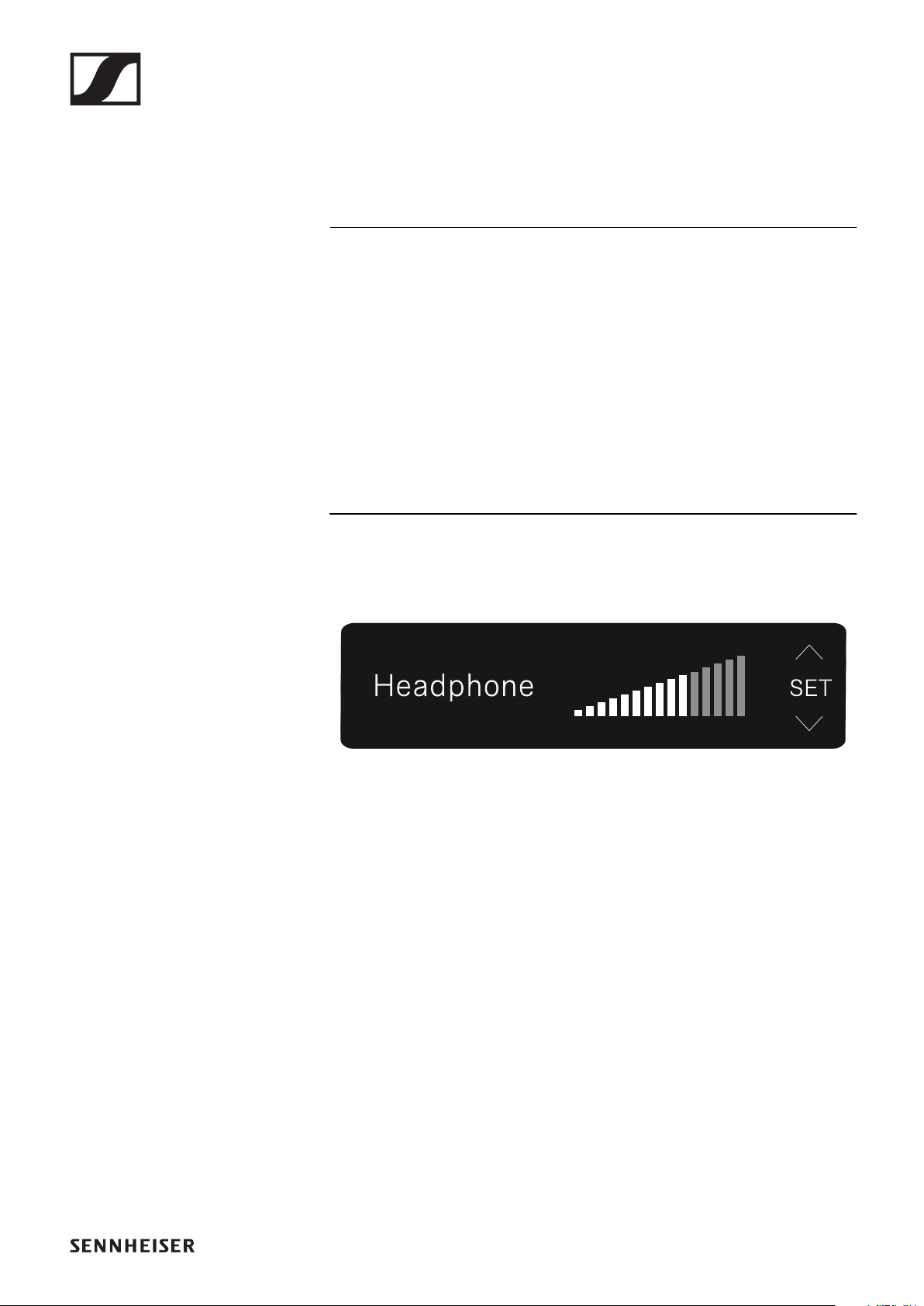
EW-DP EK portable receiver
223
Headphone menu item
Under the Headphone menu item, you can set the volume of
the audio signal coming from the receiver’s headphone output.
CAUTION
Danger due to high volume levels
Volume levels that are too high may damage your hearing.
▷Turn down the volume of the headphone output before you
put on the headphone. Recommended impedance for head-
phones (HD 25 = 70 ohms). For headphones with < 32 ohms
of impedance, the audio signal can be very loud at the low-
est volume setting.
▷Open the Headphone menu item.
The display looks as follows.
►
▷Press the UP or DOWN button to adjust the value.
▷Press the SET button to save the set value. You will then be
returned to the main view or advanced view.
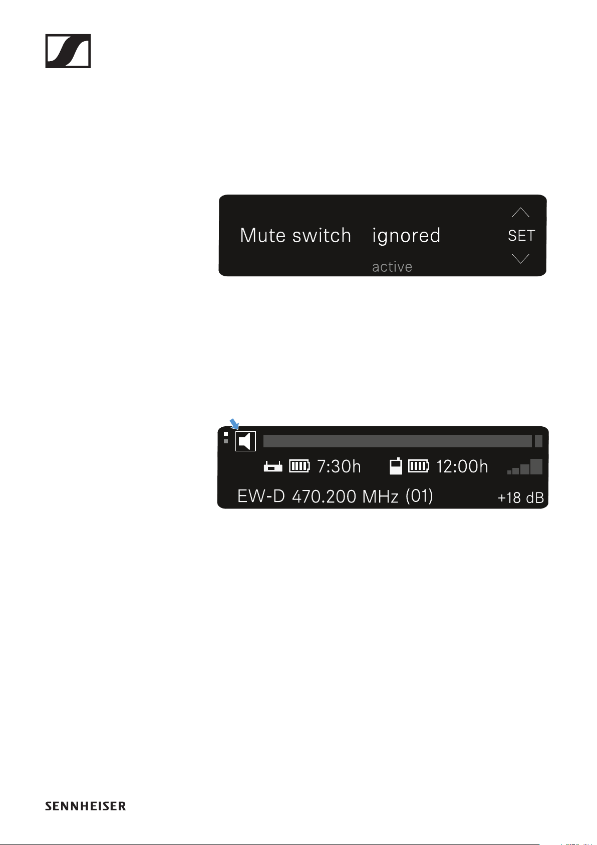
EW-DP EK portable receiver
224
MUTE switch menu item
Under the MUTE switch menu item, you can disable the mute
switch on the paired transmitter.
The transmitter can then no longer be muted.
▷Open the MUTE switch menu item.
The display looks as follows.
►
▷Press the UP or DOWN button to enable (active) or disable
(ignored) the function.
▷Press the SET button to save the set value. You will then be
returned to the main view or advanced view.
If a loudspeaker icon within a border appears on the upper
left of the display, the transmitter’s mute switch is dis-
abled.
►
►

EW-DP EK portable receiver
225
AUTO SCAN menu item
Under the AUTO SCAN menu item, you can perform an auto-
matic frequency scan of your area. This enables you to easily
find and assign free radio frequencies.
The scan starts at the lowest frequency in the device’s fre-
quency range.
▷Open the AUTO SCAN menu item.
The scan starts automatically. The next free frequency is
shown on the display.
►
▷Press the SET button to accept the displayed frequency.
You will then be returned to the main view or advanced
view.
or
▷Press the UP or DOWN button to display the next free fre-
quency above or below the current frequency.
or
▷Press the ESC button to cancel the scan.
The previous frequency remains unchanged.
If you have set a new frequency, you must still synchro-
nize the receiver with the transmitter to establish the ra-
dio link (see "Establishing a radio link | Synchronizing the
receiver and transmitter").
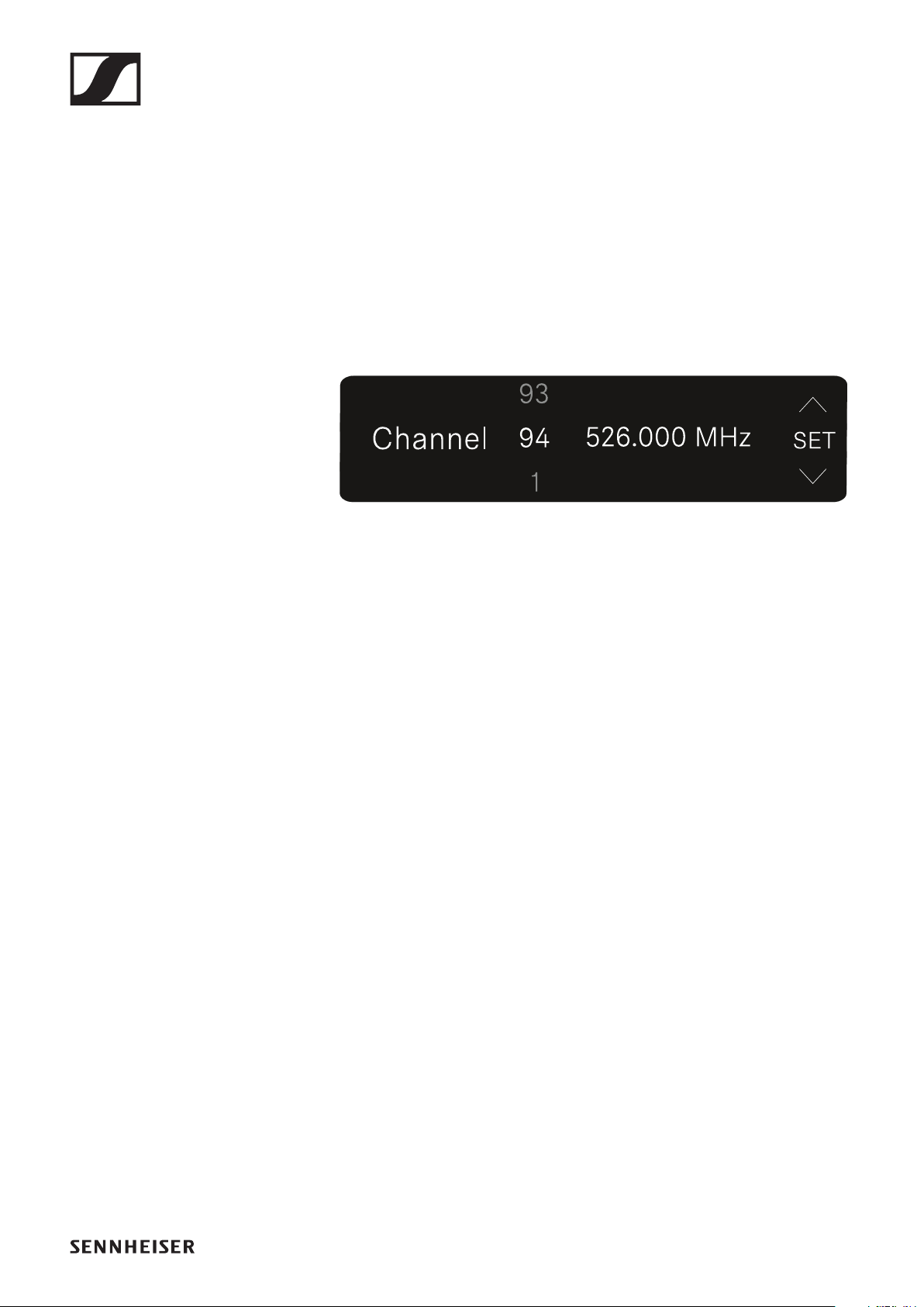
EW-DP EK portable receiver
226
CHANNEL menu item
Under the CHANNEL menu item, you can set the radio fre-
quency by selecting a preset channel.
If you are not sure whether the selected frequency is free,
we recommend performing a scan to detect all free fre-
quencies: "AUTO SCAN menu item".
▷Open the CHANNEL menu item.
The display looks as follows.
►
▷Press the UP or DOWN button to select a preset channel.
▷Press the SET button to accept the displayed frequency.
You will then be returned to the main view or advanced
view.
or
▷Press the ESC button to cancel the setting.
The previous frequency remains unchanged.
If you have set a new frequency, you must still synchro-
nize the receiver with the transmitter to establish the ra-
dio link (see "Establishing a radio link | Synchronizing the
receiver and transmitter").

EW-DP EK portable receiver
227
Frequency menu item
Under the FREQUENCY menu item, you can manually set the
radio frequency independently of the preset channels.
If you are not sure whether the selected frequency is free,
we recommend performing a scan to detect all free fre-
quencies: "AUTO SCAN menu item".
▷Open the FREQUENCY menu item.
The display looks as follows.
►
▷Press the UP or DOWN button to set the frequency in the
megahertz range.
▷Press the SET button to select the value and activate fine-
tuning of the frequency in the kilohertz range.
►
▷Press the UP or DOWN buttons to finely adjust the frequen-
cy in the kilohertz range.
▷Press the SET button to accept the displayed frequency.
You will then be returned to the main view or advanced
view.
or
▷Press the ESC button to cancel the setting.
The previous frequency remains unchanged.
If you have set a new frequency, you must still synchro-
nize the receiver with the transmitter to establish the ra-
dio link (see "Establishing a radio link | Synchronizing the
receiver and transmitter").
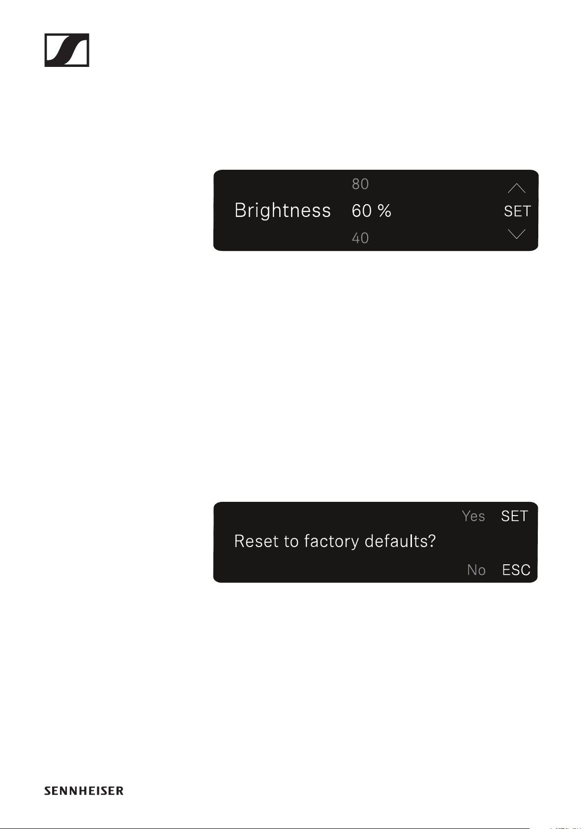
EW-DP EK portable receiver
228
BRIGHTNESS menu item
Under the BRIGHTNESS menu item, you can set the bright-
ness of the display.
▷Open the BRIGHTNESS menu item.
The display looks as follows.
►
▷Press the UP or DOWN button to set the desired bright-
ness.
►
▷Press the SET button to save the set value. You will then be
returned to the main view or advanced view.
RESET menu item
Under the RESET menu item, you can reset the receiver to its
factory settings.
▷Open the RESET menu item.
The display looks as follows.
►
▷Press the SET or ESC button to switch between the options
YES and NO.
►
YES: The receiver is reset to its factory settings.
NO: The receiver is not reset.
▷You will then be returned to the main view or advanced
view.
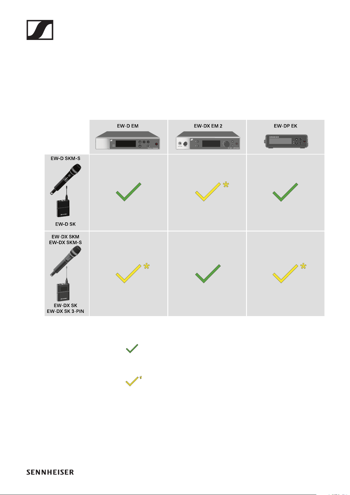
Establishing a radio link | Synchronizing the receiver and transmitter
229
Establishing a radio link | Synchronizing
the receiver and transmitter
Information on compatibility between EW-D, EW-
DX and EW-DP
The transmitter and the receiver are fully compatible
with each other.
The transmitter and the receiver are compatible with
each other. Some features may not be available.
Conditions and restrictions for using frequencies
There may be special conditions and restrictions for using fre-
quencies in your country.
Before putting the product into operation, find the information
for your country at the following address:
www.sennheiser.com/sifa
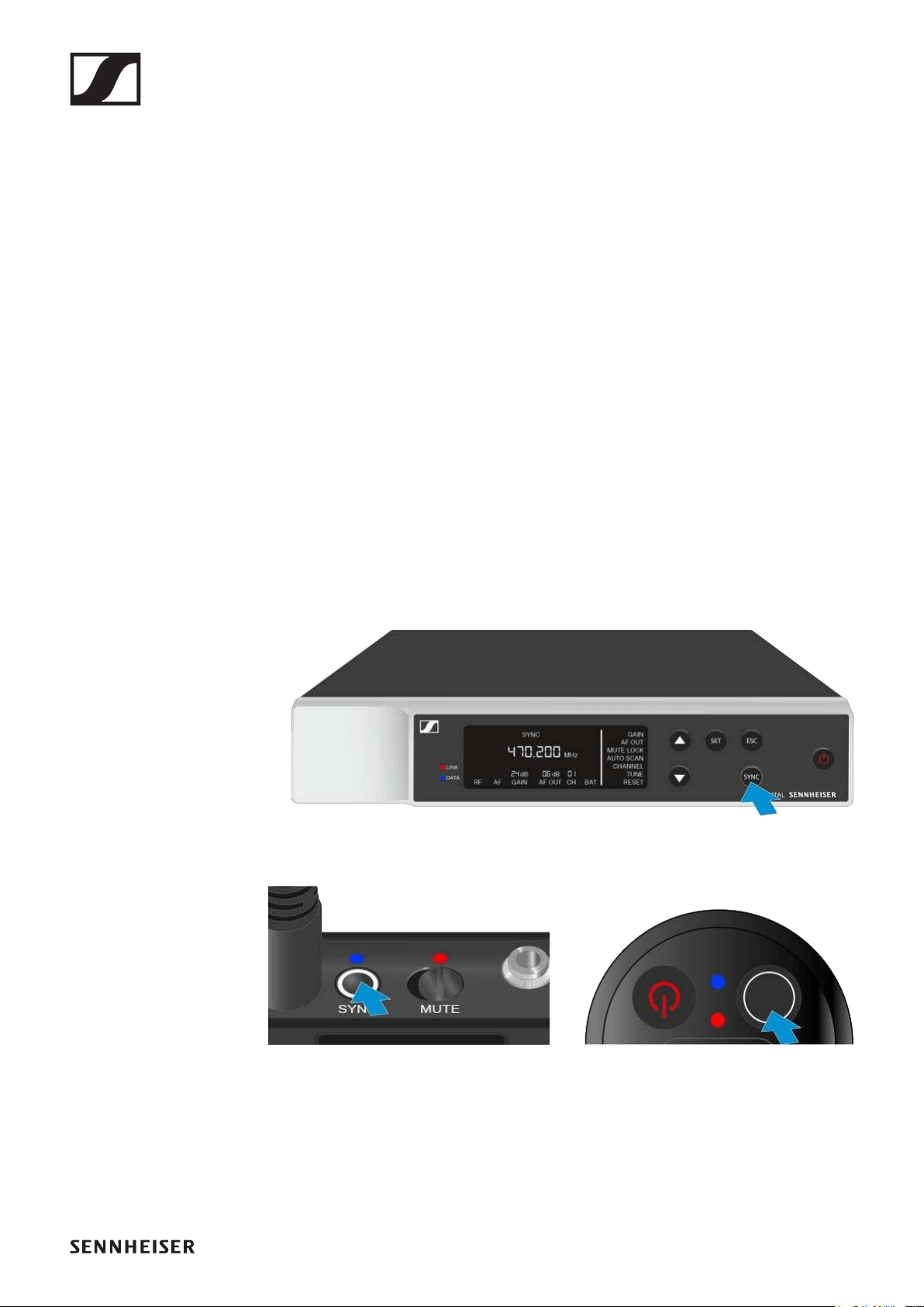
Establishing a radio link | Synchronizing the receiver and transmitter
230
Connecting to the EW-D EM receiver /
synchronizing the EW-D EM
To establish a radio link between the transmitter and receiver,
we recommend the following procedure.
In order to establish a connection between a receiver and
transmitters of the EW-D series, the devices must always be
synchronized with each other.
To successfully connect a receiver and a transmitter, both de-
vices must have the same frequency range.
Step 1: Set a free frequency
We recommend using the AUTO SCAN function, as this is the
most reliable way to identify free frequencies (see "AUTO
SCAN menu item").
If you know free frequencies in your area, you can also set the
frequency manually (see "CHANNEL menu item" or "TUNE
menu item").
Step 2: Pairing a receiver with a transmitter
▷Short-press the SYNC button on the receiver.
The blue DATA LED flashes.
►
▷Short-press the SYNC button on the transmitter.
The blue DATA LED flashes.
►
The transmitter and receiver will be paired. Once the link is
established, the LINK LED on both units will light up green.
Be sure to press the SYNC button on all devices only briefly
(less than 2 seconds). Holding the SYNC button longer than
this will start the firmware update mode and cancel the syn-
chronization process.
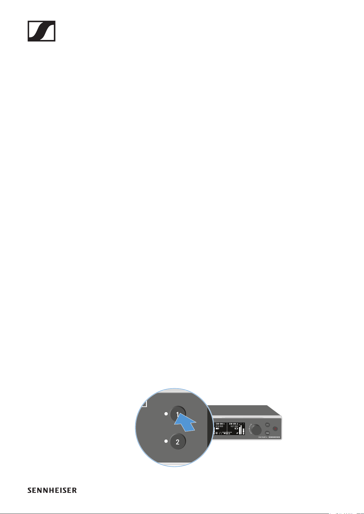
Establishing a radio link | Synchronizing the receiver and transmitter
231
Connecting to the EW-DX EM 2 receiver /
synchronizing the EW-DX EM 2
To establish a radio link between the transmitter and receiver,
we recommend the following procedure.
In order to establish a connection between a receiver and
transmitters of the EW-D series, the devices do not necessar-
ily have to be synchronized with each other.
To successfully connect a receiver and a transmitter, both de-
vices must have the same frequency range.
Set a free frequency
We recommend using the Auto Setup function, as this is the
most reliable way to identify free frequencies (see "Ch 1 / Ch 2
-> Scan / Auto Setup menu item").
If you know free frequencies in your area, you can also set the
frequency manually.
▷EW-DX EM 2: "Ch 1 / Ch 2 -> Frequency menu item"
▷EW-DX SKM(-S): "Making settings in the menu of the hand-
held transmitter"
▷EW-DX SK (3-PIN): "Making settings in the menu of the
bodypack transmitter"
Once you have set the same frequency for the desired receiv-
ing channel on the receiver and for the transmitter you want to
connect, the radio link is established.
To ensure that all settings are transmitted to the transmitter,
we recommend synchronizing the transmitter with the receiv-
ing channel.
Synchronizing the receiver and transmitter
To synchronize the receiver and the transmitter:
▷On the receiver, press the CH 1 or CH 2 button to select the
channel you want to synchronize.
▷Press the SYNC button on the receiver.
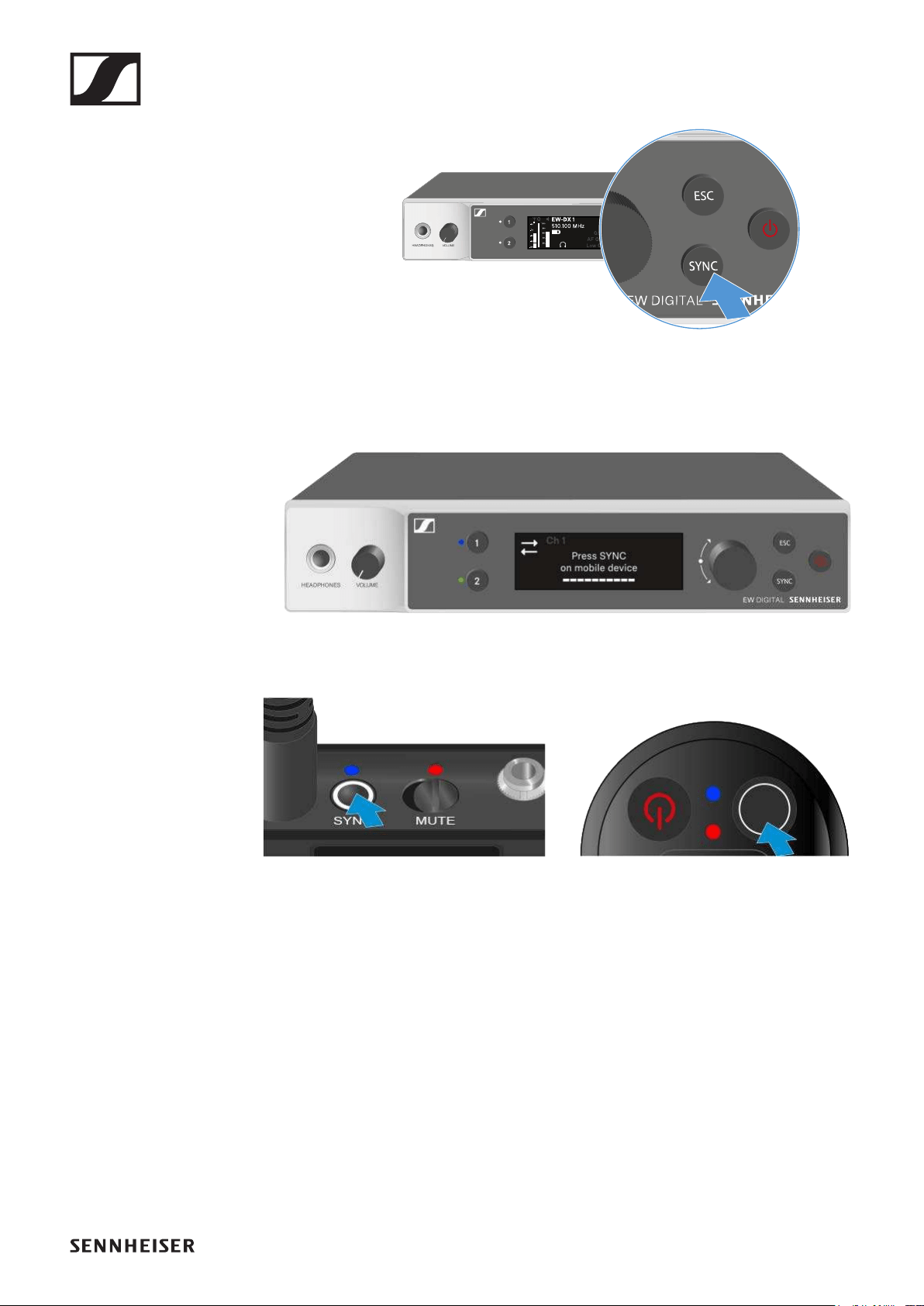
Establishing a radio link | Synchronizing the receiver and transmitter
232
The receiver’s display shows that the synchronization pro-
cess has started.
The LED for the selected receiving channel flashes blue.
▷Short-press the SYNC button on the transmitter.
The blue DATA LED flashes.
►
The transmitter and receiver will be synchronized.
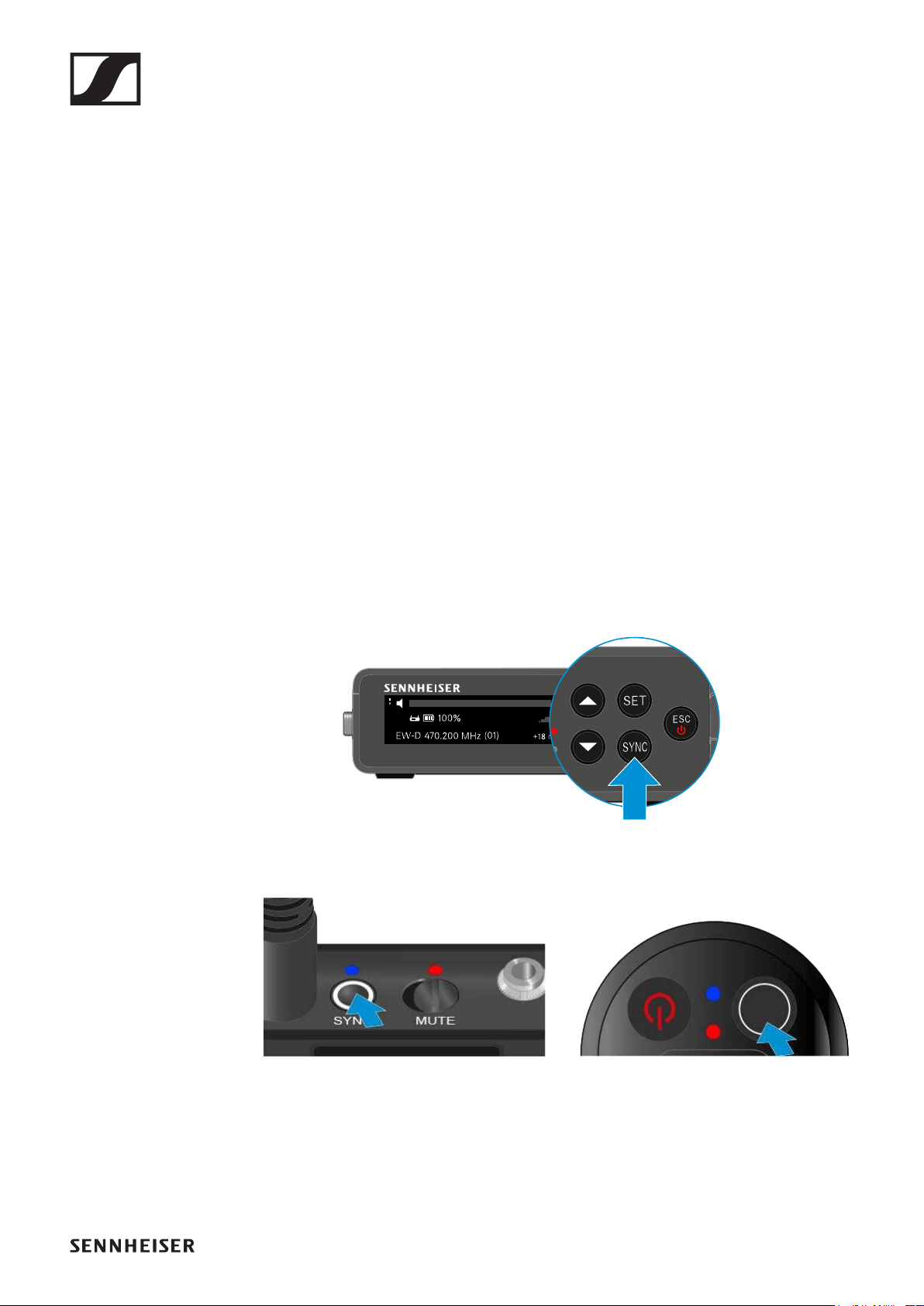
Establishing a radio link | Synchronizing the receiver and transmitter
233
Connecting to the EW-DP EK receiver / syn-
chronizing the EW-DP EK
To establish a radio link between the transmitter and receiver,
we recommend the following procedure.
In order to establish a connection between a receiver and
transmitters of the EW-DP EK series, the devices must always
be synchronized with each other.
To successfully connect receivers and transmitters, both de-
vices must have the same frequency range.
Step 1: Set a free frequency
We recommend using the AUTO SCAN function, as this is the
most reliable way to identify free frequencies (see "AUTO
SCAN menu item").
If you know free frequencies in your area, you can also set the
frequency manually (see "CHANNEL menu item" or "Frequen-
cy menu item").
Step 2: Pairing a receiver with a transmitter
▷Short-press the SYNC button on the receiver.
The blue DATA LED flashes.
►
▷Short-press the SYNC button on the transmitter.
The blue DATA LED flashes.
►
The transmitter and receiver will be paired. Once the link is
established, the LINK LED on both units will light up green.
Be sure to press the SYNC button on all devices only briefly
(less than 2 seconds). Holding the SYNC button longer than
this will start the firmware update mode and cancel the syn-
chronization process.
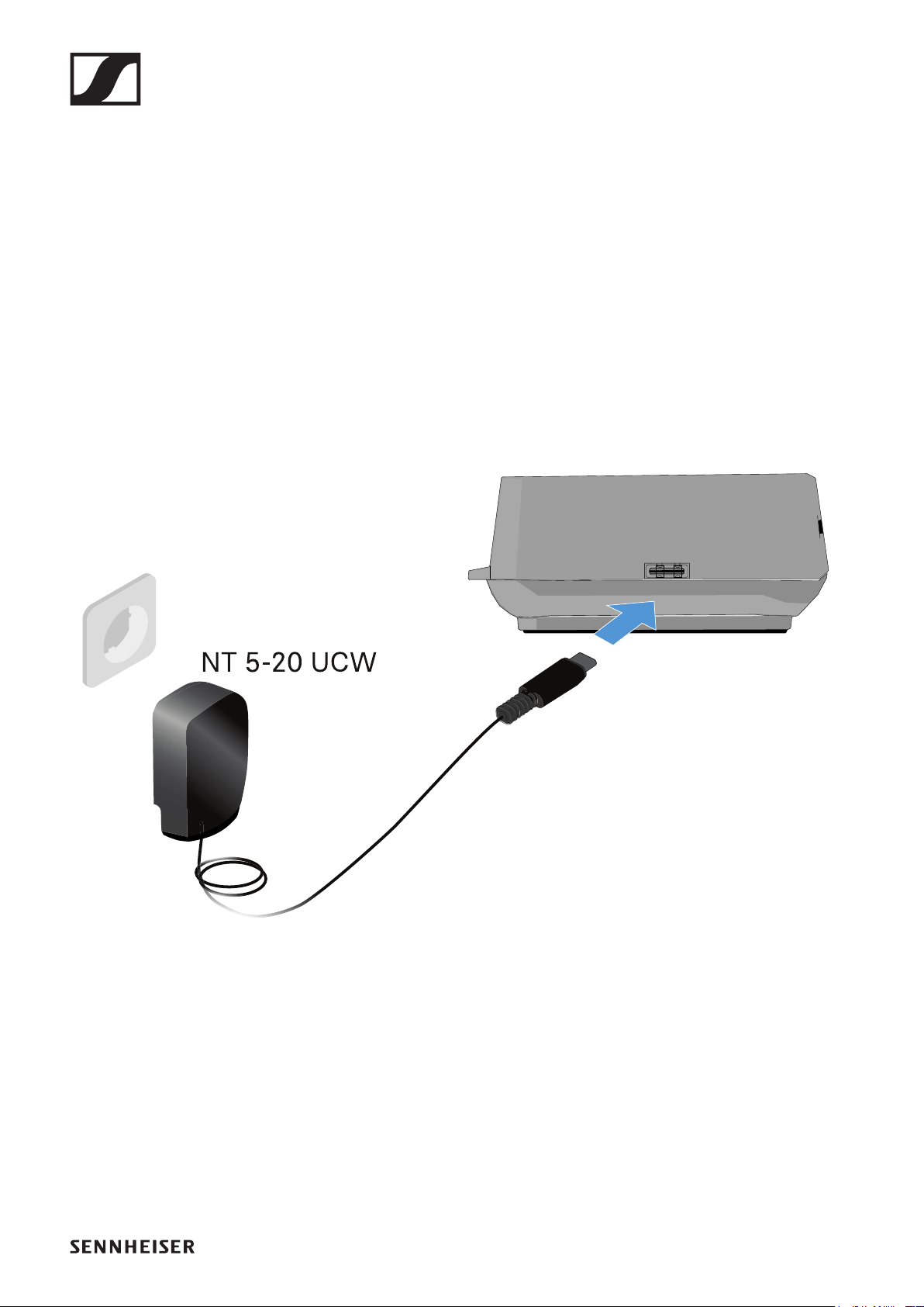
Charging the BA 70 rechargeable battery in the L 70 USB charger
234
Charging the BA 70 rechargeable bat-
tery in the L 70 USB charger
Connecting/disconnecting the charger to/
from the power supply system
To connect the charger to the power supply system:
▷Use only the NT 5-20 UCW power supply unit from Sennhe-
iser.
▷Connect the USB-C plug on the charging cable to the USB-
C port on the side of the charger.
▷Plug the power supply unit with the correct country adapter
into a suitable power outlet.
To disconnect the charger from the power supply system:
▷Unplug the power supply unit from the wall socket.
▷Remove the USB-C plug on the charging cable from the
USB-C port on the side of the charger.
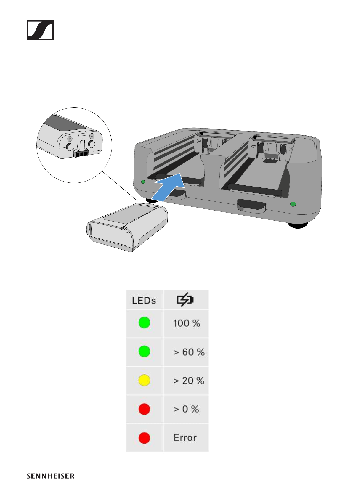
Charging the BA 70 rechargeable battery in the L 70 USB charger
235
Charging the rechargeable battery
To charge the BA 70 rechargeable battery in the L 70 USB
charger:
▷Slide the rechargeable battery completely into the charging
slot as shown in the figure.
►
The rechargeable battery will begin charging.
The LED on the charging slot shows the battery’s charge level:
►
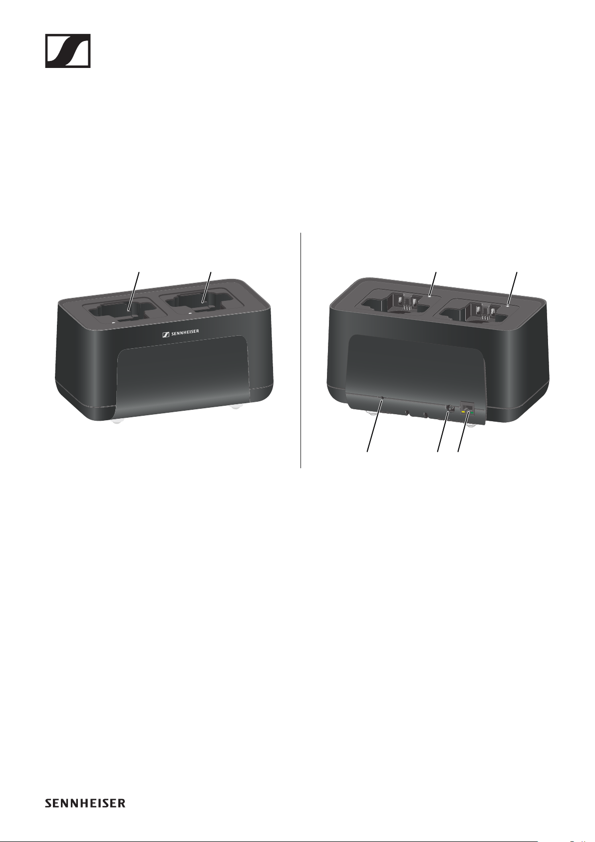
Charging the EW-DX SKM(-S) handheld transmitter, the EW-DX SK (3-PIN) bodypack transmitter or the BA 70
236
Charging the EW-DX SKM(-S) handheld
transmitter, the EW-DX SK (3-PIN)
bodypack transmitter or the BA 70 re-
chargeable battery in the CHG 70N char-
ger
Product overview
1Charging slots
•See "Charging the rechargeable battery"
2Status LEDs of the charging slots
•See "Charging the rechargeable battery"
3Reset button
•Press to reset the device’s network settings.
•See "Connecting a charger in a network"
•Press and hold to enable power saving mode.
•See "Power saving mode"
4DC in connection socket for the NT 12-35 CS power supply
unit
•See "Connecting/disconnecting the charger to/from the
power supply system"
5PoE/Ethernet RJ-45 socket for controlling the device over
the network and for Power over Ethernet power supply
•See "Connecting a charger in a network"
•See "Connecting/disconnecting the charger to/from the
power supply system"
11
345
22
Front Back
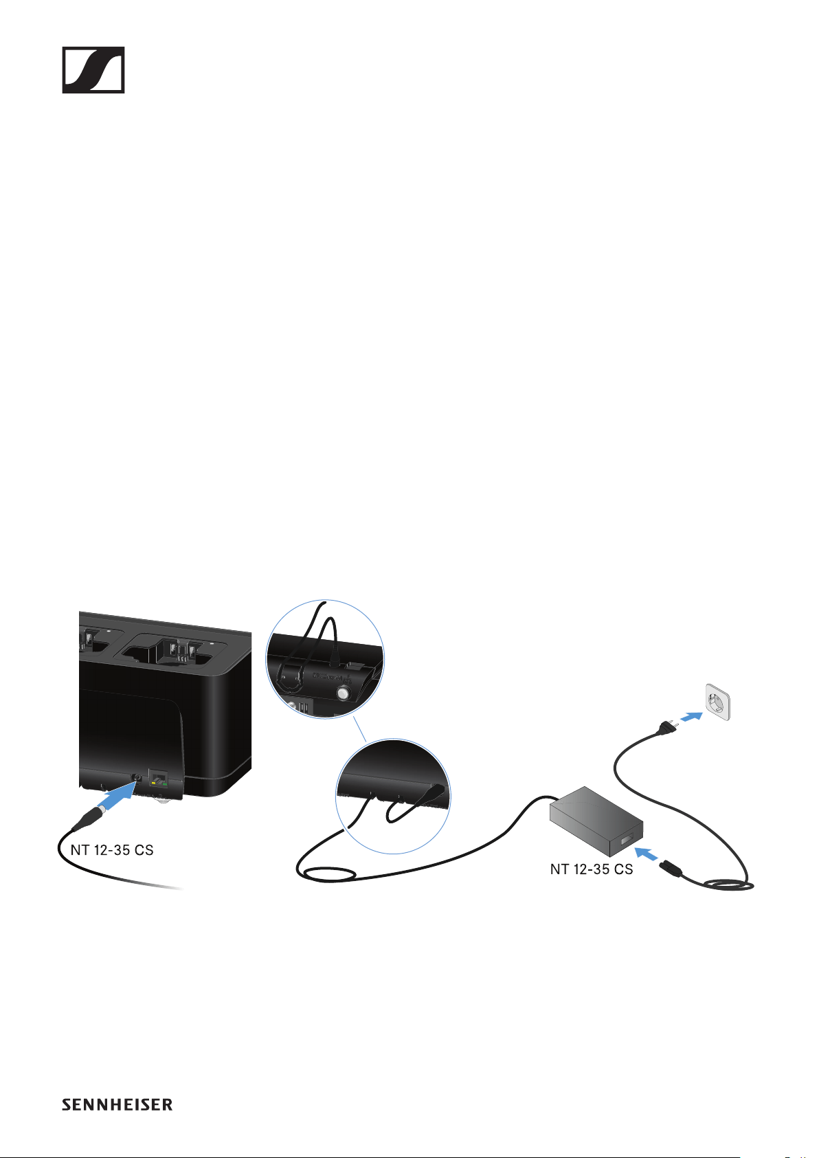
Charging the EW-DX SKM(-S) handheld transmitter, the EW-DX SK (3-PIN) bodypack transmitter or the BA 70
237
Connecting/disconnecting the charger to/
from the power supply system
You can operate the charger either with the Sennheiser NT 12-
35 CS power supply unit or with Power over Ethernet (PoE
IEEE 802.3af Class 0). Please refer to the following informa-
tion.
Power from the NT 12-35 CS power supply unit
Use only the NT 12-35 CS power supply unit from Sennheiser.
It is designed for your charger and ensures safe operation.
The power supply unit is available either separately (Sennhe-
iser article number 508995) or together with the charger as a
kit (see "CHG 70N network-enabled charger").
To connect the charger to the power supply system:
▷Connect the hollow jack plug of the power supply unit to
the DC in socket on the charger.
▷Pass the cable through the strain relief.
▷Plug the power supply unit into the wall outlet using the
correct power cable for your country.
To completely disconnect the charger from the power supply
system:
▷Unplug the power cable from the wall socket.
▷Unplug the hollow jack plug of the power supply unit from
the DC in socket on the charger.
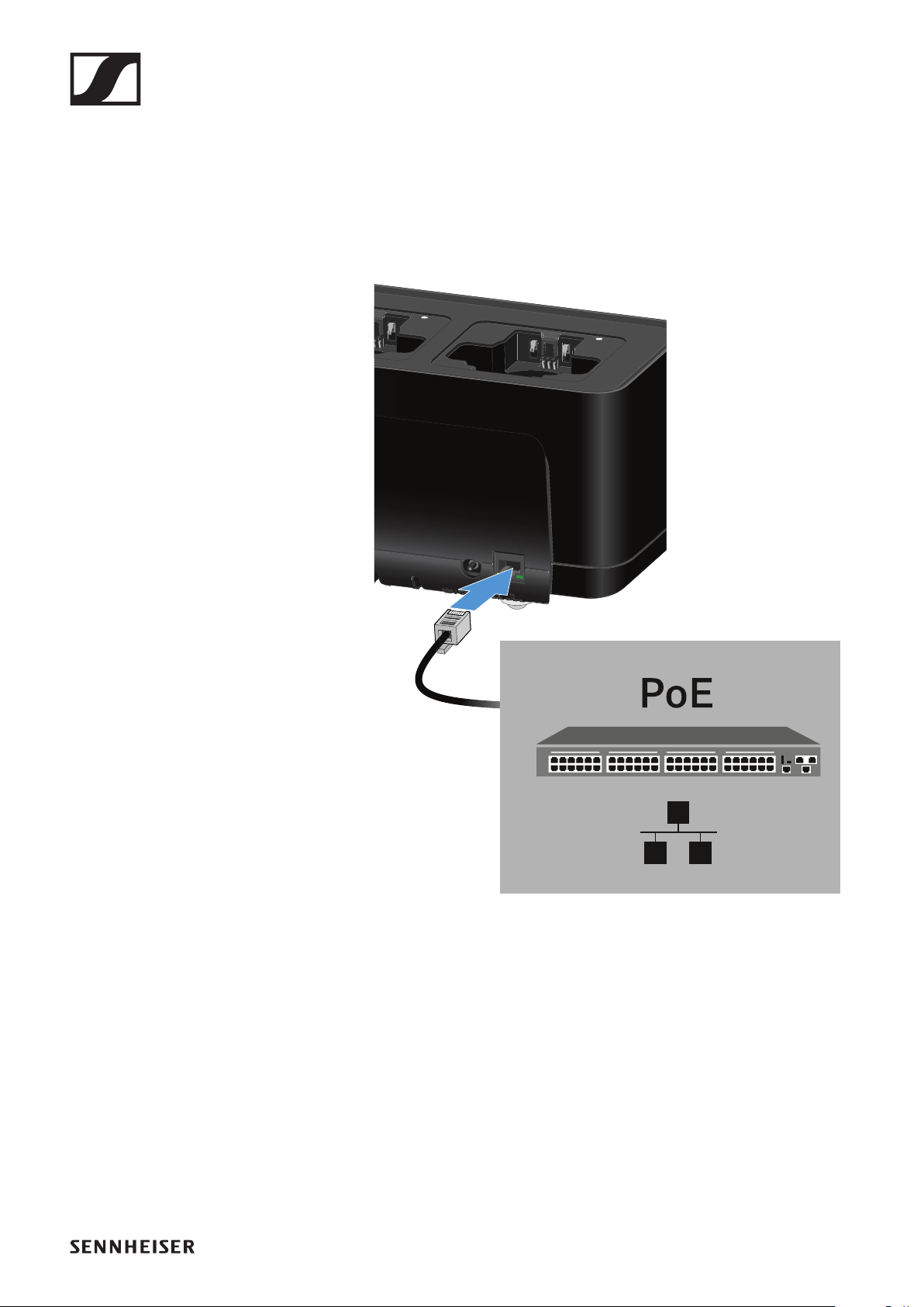
Charging the EW-DX SKM(-S) handheld transmitter, the EW-DX SK (3-PIN) bodypack transmitter or the BA 70
238
Power over Ethernet (PoE)
The charger can be powered via Power over Ethernet (PoE
IEEE 802.3af Class 0).
▷Connect the charger to a PoE-enabled network switch.
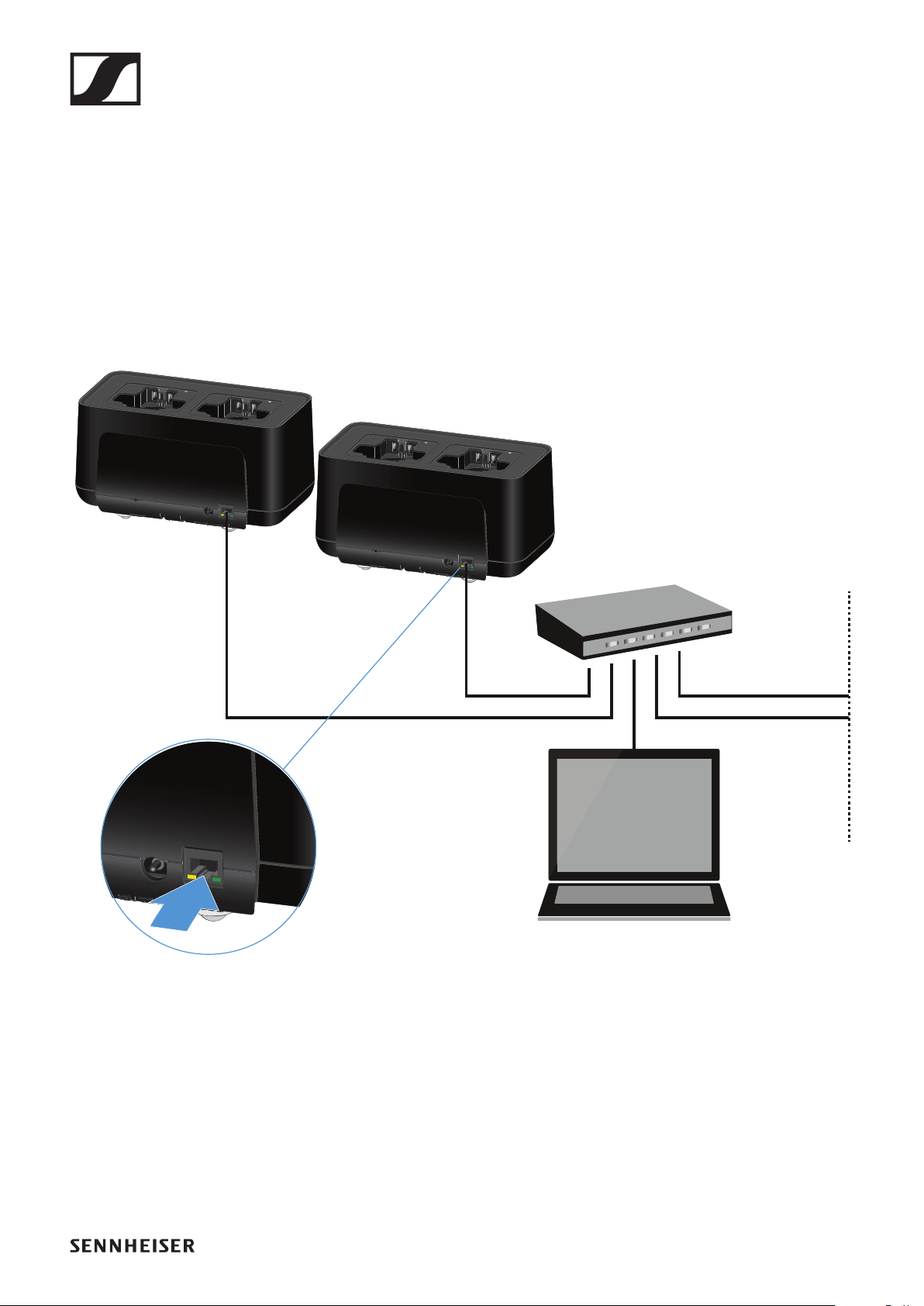
Charging the EW-DX SKM(-S) handheld transmitter, the EW-DX SK (3-PIN) bodypack transmitter or the BA 70
239
Connecting a charger in a network
You can monitor and control one or more chargers via a net-
work connection using the Sennheiser Wireless Systems
Manager (WSM) or Sennheiser Control Cockpit (SCC) soft-
ware.
The network does not have to be a homogeneous network in-
cluding only chargers. You can integrate the charger into your
existing network infrastructure with any other types of devic-
es.
For more information about controlling devices via the Senn-
heiser Wireless Systems Manager or Sennheiser Control
Cockpit software, refer to the instruction manual for the soft-
ware. You can download the software here:
www.sennheiser.com/wsm
www.sennheiser.com/control-cockpit-software

Charging the EW-DX SKM(-S) handheld transmitter, the EW-DX SK (3-PIN) bodypack transmitter or the BA 70
240
Charging the rechargeable battery
You can use the CHG 70N charger to charge individual BA 70
rechargeable batteries, or to charge EW-DX SKM, EW-DX
SKM-S, EW-DX SK or EW-DX SK 3-PIN transmitters with the
BA 70 rechargeable battery already inserted.
To charge the battery:
▷Insert the individual rechargeable battery or the transmit-
ter with battery already inserted into the charging slot as
shown in the figure.
►
The rechargeable battery will begin charging.
The LED on the charging slot shows the battery’s charge level.

Charging the EW-DX SKM(-S) handheld transmitter, the EW-DX SK (3-PIN) bodypack transmitter or the BA 70
241
Power saving mode
In power saving mode, the transmitters are charged only once.
The charger also does not provide any trickle charge.
To activate power saving mode:
▷Remove all transmitters and/or rechargeable batteries
from the charging slots.
▷Hold the Reset button for 4 seconds.
The charging slot LEDs light up purple.
▷Insert the rechargeable battery/transmitter for charging.
The rechargeable battery will begin charging. The charging
slot LED turns green once it reaches full charge.
In power saving mode, the CHG 70N cannot be controlled over
the network.
To deactivate power saving mode:
▷Disconnect the charger from the power supply system.
▷Then reconnect it to the power supply system.
The charger will start up in the configuration that was set
before you activated power saving mode.

EW-D ASA antenna splitter
242
EW-D ASA antenna splitter
Product overview
1STANDBY button
•See "Switching the EW-D ASA on and off"
2LED: Operation indicator
•See "Switching the EW-D ASA on and off"
34 BNC sockets B1 to B4
•RF outputs of diversity branch B for connection to the re-
ceiver
•See "Connecting receivers to the EW-D ASA"
4ANT RF IN B BNC socket
•Antenna input of diversity branch B
•See "Connecting antennas"

EW-D ASA antenna splitter
243
5ANT RF IN A BNC socket
•Antenna input of diversity branch A
•See "Connecting antennas"
64 BNC sockets A1 to A4
•RF outputs of diversity branch A for connection to the re-
ceiver
•Each one of these RF outputs can also provide power to
an EW-D EM receiver
•See "Connecting receivers to the EW-D ASA"
7RF OUT A BNC socket
•RF output only for connecting an additional ASA 214 to
build an 8-channel diversity system
•See "Configuring multi-channel systems"
8DC in socket
•To connect the NT 12-35 CS power supply unit
•See "Connecting/disconnecting the EW-D ASA to/from
the power supply system"
9Strain relief for the connection cable of the power supply
unit
•See "Connecting/disconnecting the EW-D ASA to/from
the power supply system"
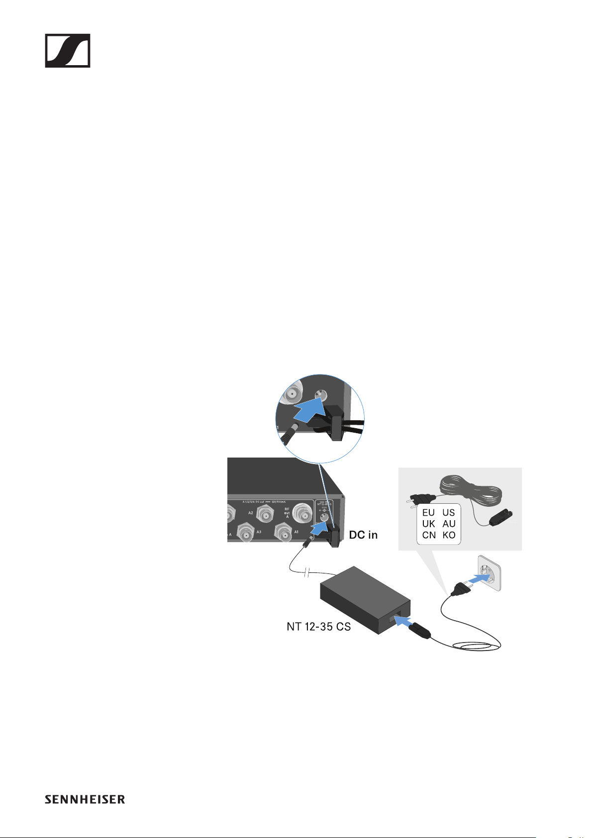
EW-D ASA antenna splitter
244
Connecting/disconnecting the EW-D ASA
to/from the power supply system
To supply power to the EW-D ASA, the connected receivers
(EW-D EM only) and any antenna amplifiers used, you will
need the NT 12-35 CS power supply unit.
Use only the supplied NT 12-35 CS power supply unit. It is de-
signed for your antenna splitter and ensures safe operation.
To connect the EW-D ASA antenna splitter to the power sup-
ply system:
▷Plug the hollow jack plug of the power supply unit into the
DC in socket of the antenna splitter.
▷Pass the cable of the power supply unit through the strain
relief.
▷Connect one end of the power cord to the power supply unit
and the other end to the wall socket.
To completely disconnect the EW-D ASA antenna splitter
from the power supply system:
▷Unplug the power cable from the wall socket.
▷Unplug the hollow jack plug of the power supply unit from
the DC in socket of the antenna splitter.
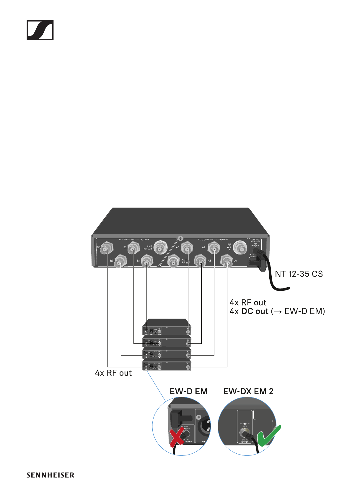
EW-D ASA antenna splitter
245
Connecting receivers to the EW-D ASA
You can connect and operate up to four EW-D EM or EW-
DX EM 2 rack receivers with the EW-D ASA.
To connect the receivers to the EW-D ASA antenna splitter:
▷Connect one of the receiver’s antenna inputs to one of the
BNC sockets A1 to A4 using one of the supplied BNC ca-
bles.
The EW-D EM receivers do not require their own power
supply. They are powered via the BNC sockets A1 to A4.
The EW-DX EM 2 receivers cannot be supplied with power
via the BNC sockets. They need to be powered by the in-
cluded power supply unit or by PoE.
▷Connect the receiver’s other antenna input to one of the
BNC sockets B1 to B4 using one of the supplied BNC ca-
bles.
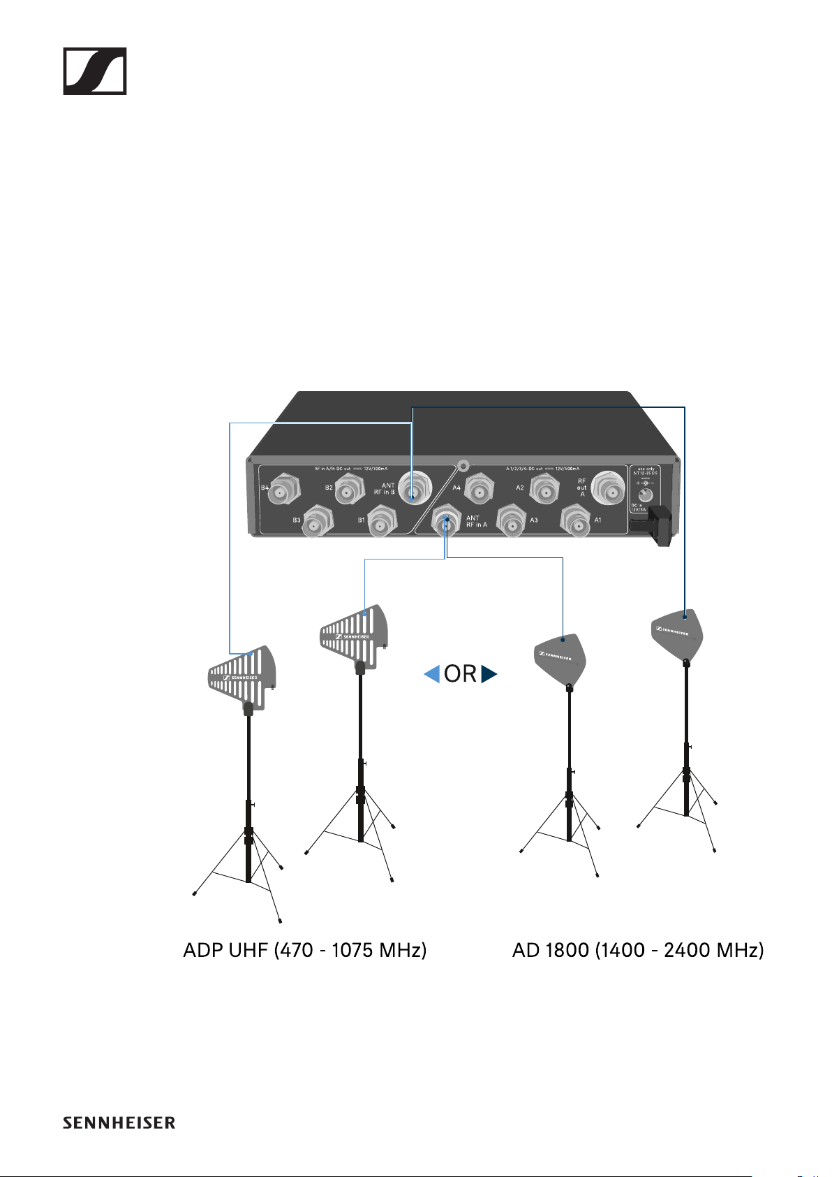
EW-D ASA antenna splitter
246
Connecting antennas
To ensure optimal reception even in the case of poor reception
conditions, we recommend using remote antennas.
Connecting remote antennas
▷Mount an antenna each or a combination of an antenna and
an antenna amplifier to the BNC sockets ANT RF IN A and
ANT RF IN B.
▷Refer to the instructions under "Information on antenna
amplifiers and cable lengths".
Connecting rod antennas
▷Mount the antennas to the BNC sockets ANT RF IN A and
ANT RF IN B.
▷Align the antennas in a V-shape in order to ensure the best
possible reception.
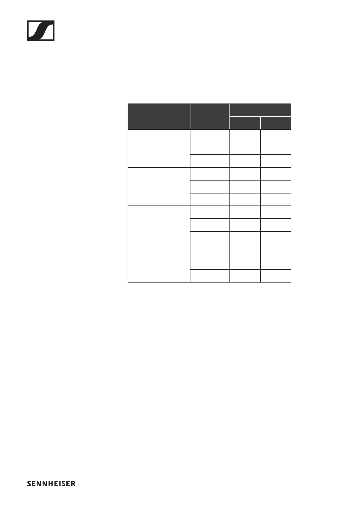
EW-D ASA antenna splitter
247
Information on antenna amplifiers and cable
lengths
The following table shows which cable lengths require the use
of the EW-D AB antenna amplifier as well as the maximum
recommended cable lengths.
Frequency variants of the EW-DAB: "EW-D AB antenna boost-
er"
Max. cable length
RG 58 GZL 5000
Number of
EW-D AB
Frequency
range around
500 MHz 0 8 m 16 m
1 36 m 72 m
2 64 m 128 m
0 7 m 14 m
1 30 m 60 m
2 53 m 106 m
0 6 m 12 m
1 26 m 52 m
2 46 m 92 m
0
700 MHz
900 MHz
1800 MHz 4 m 8 m
1 16 m 36 m
2 28 m 64 m
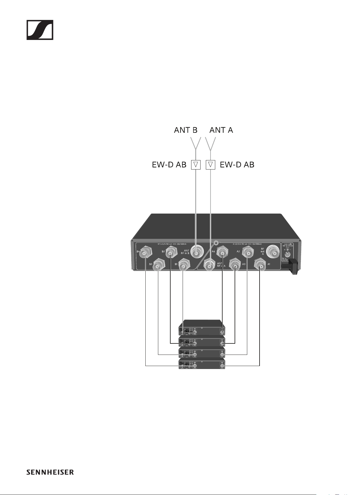
EW-D ASA antenna splitter
248
Configuring multi-channel systems
The following options for connecting multi-channel systems
are possible:
Option 1: Two antennas supply a 4-channel system
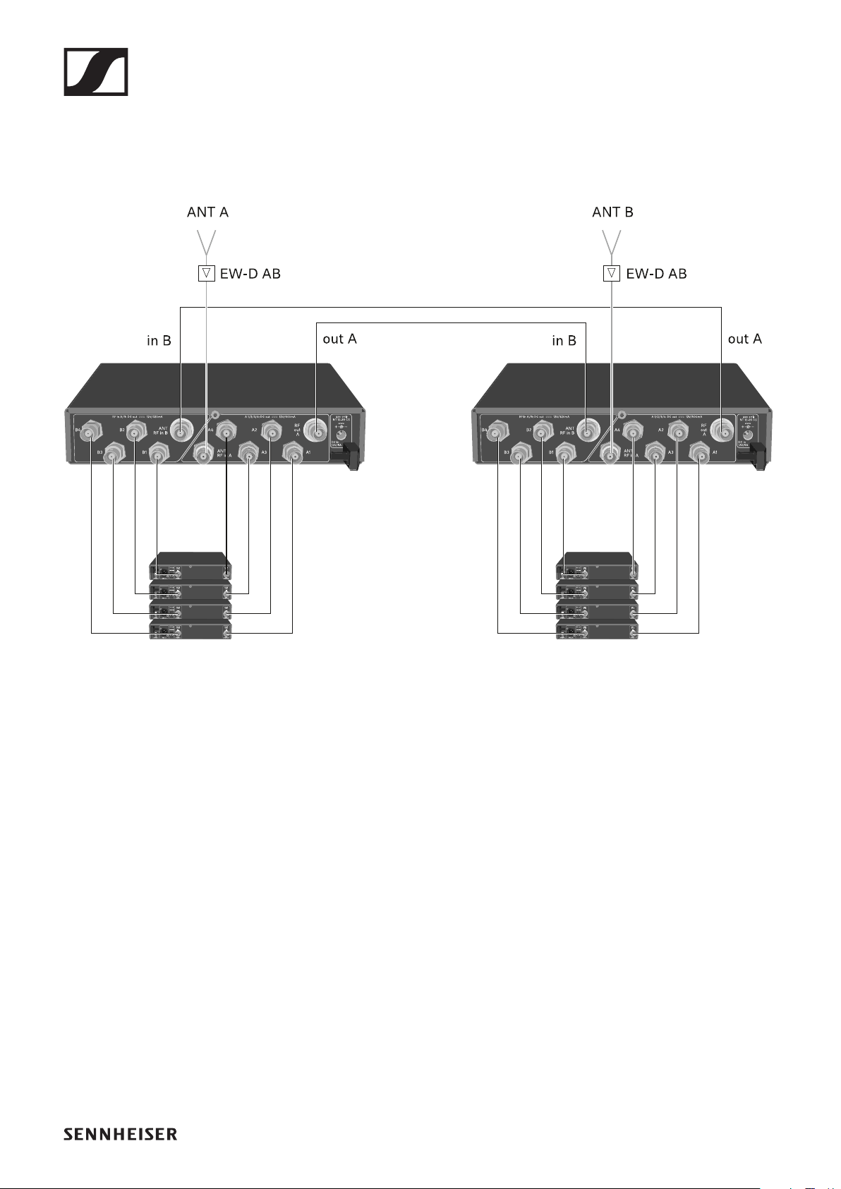
EW-D ASA antenna splitter
249
Option 2: Two 4-channel systems are interconnect-
ed
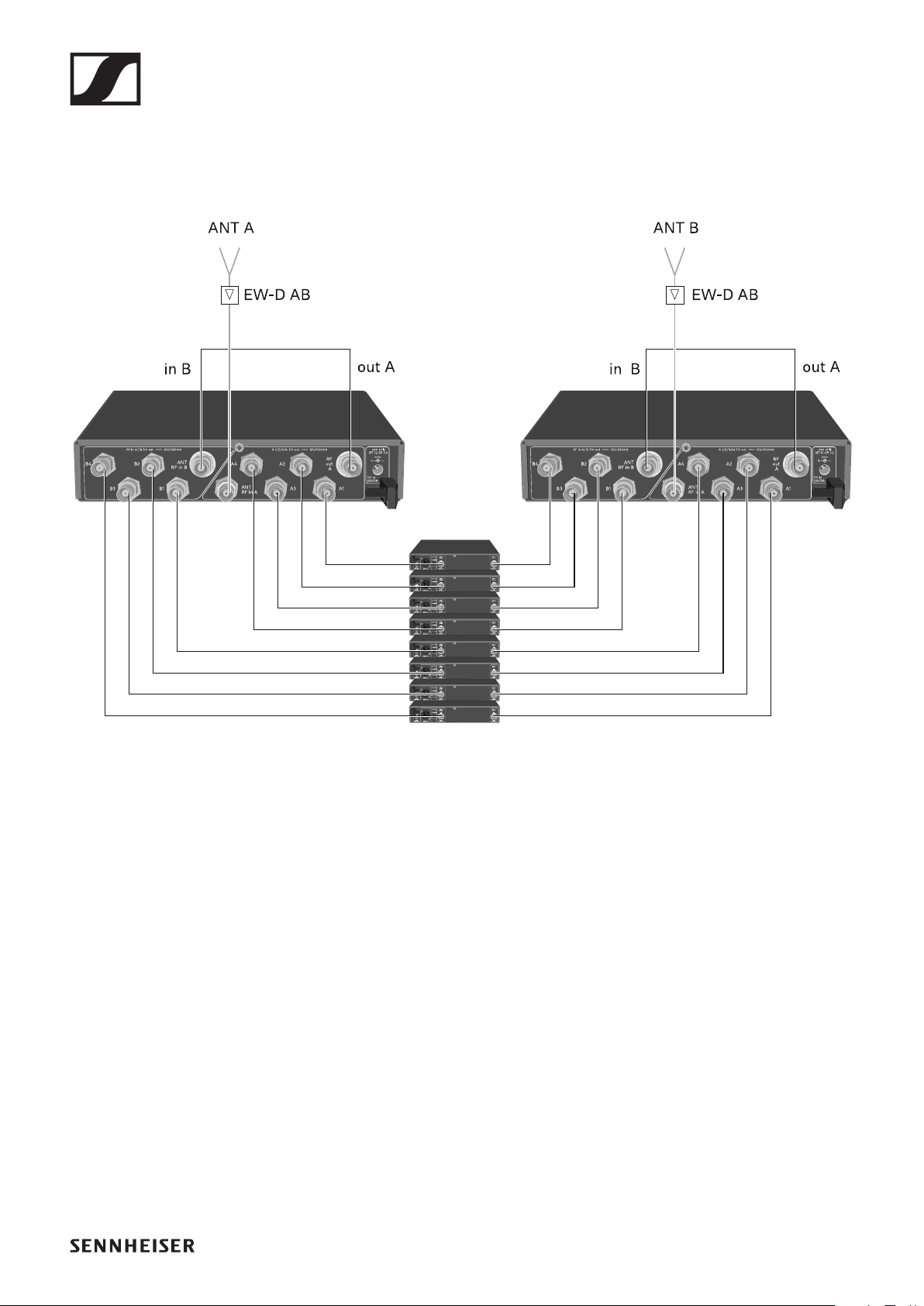
EW-D ASA antenna splitter
250
Option 3: Two antennas supply a 8-channel system

EW-D ASA antenna splitter
251
Installing the EW-D ASA in a rack
ATTENTION
Rack mounting poses risks
When installing the device in a closed 19" rack or multi-rack
assembly, please consider that, during operation, the ambient
temperature, the mechanical load and the electrical potentials
will be different from those of devices which are not mounted
into a rack.
▷Make sure that the ambient temperature within the rack
does not exceed the permissible temperature limit stated
in the specifications. See "SPECIFICATIONS".
▷Ensure sufficient ventilation; if necessary, provide addi-
tional ventilation.
▷Make sure that the mechanical load of the rack is even.
▷When connecting to the power supply system, observe the
information indicated on the type plate. Avoid overloading
the circuits. If necessary, provide overcurrent protection.
▷When mounting in a rack, please note that intrinsically
harmless leakage currents of the individual power supply
units may accumulate, thereby exceeding the permissible
limit value. As a remedy, ground the rack via an additional
ground connection.
To mount the antenna splitter in a rack, you will need the GA 3
rack mount kit (optional accessory).
Rack mounting is carried out in the same way as for the EW-
D EM receiver: "Installing receivers in a rack".
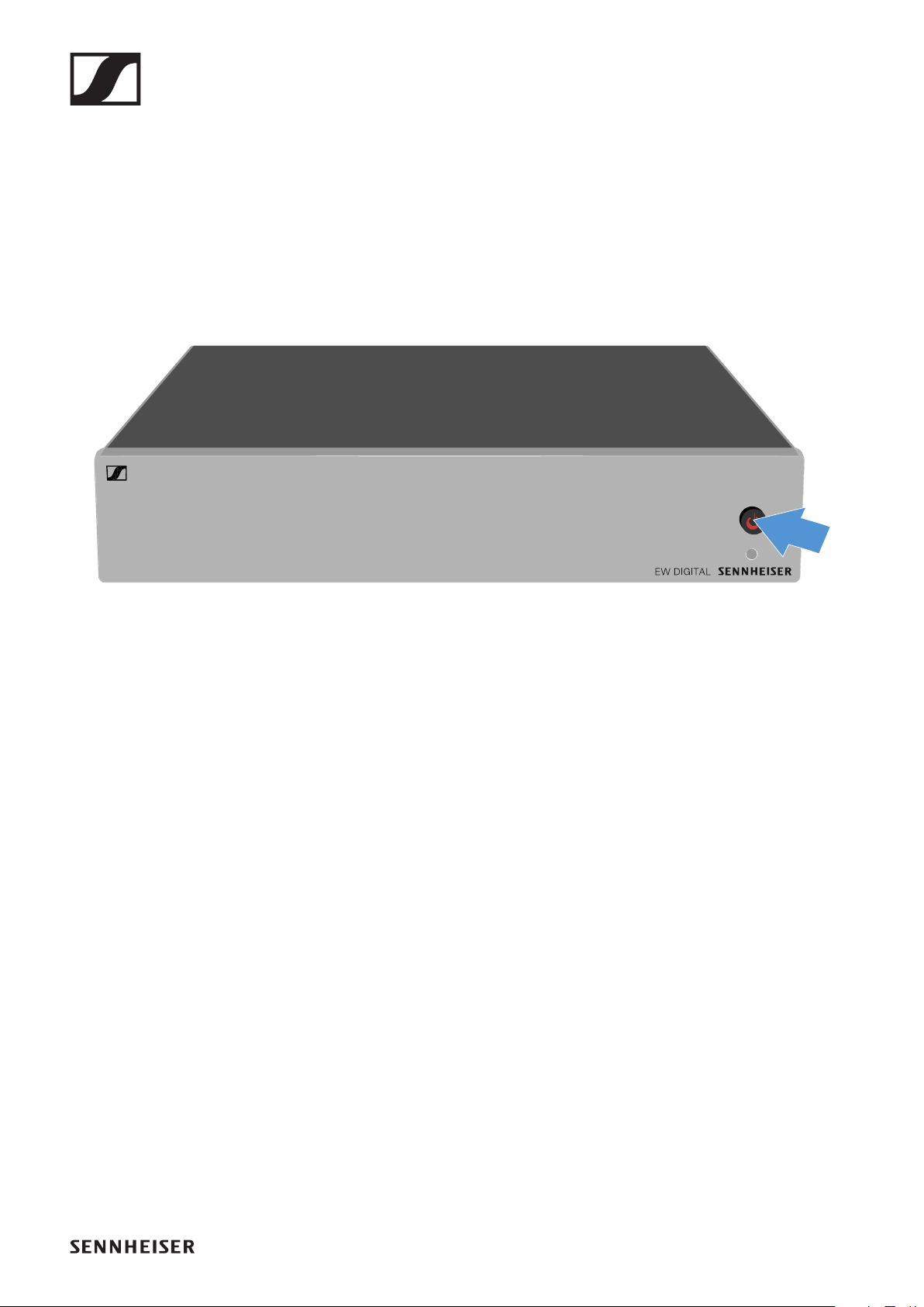
EW-D ASA antenna splitter
252
Switching the EW-D ASA on and off
To switch on the antenna splitter:
▷Short-press the STANDBY button.
The antenna splitter switches on and the power LED turns
green.
The RF signals of the connected antennas are distributed to
all connected receivers.
To switch the antenna splitter to
standby mode:
▷Press the STANDBY button for approx. 2 seconds.
The LED turns off. The connected antenna amplifiers are
switched off. Connected receivers are switched off if they
draw their supply voltage from the BNC sockets A1 to A4
(see "Connecting receivers to the EW-D ASA").
To
fully switch off the antenna splitter:
▷Disconnect the antenna splitter from the power supply sys-
tem by unplugging the power supply unit from the wall
socket.
The LED turns off.
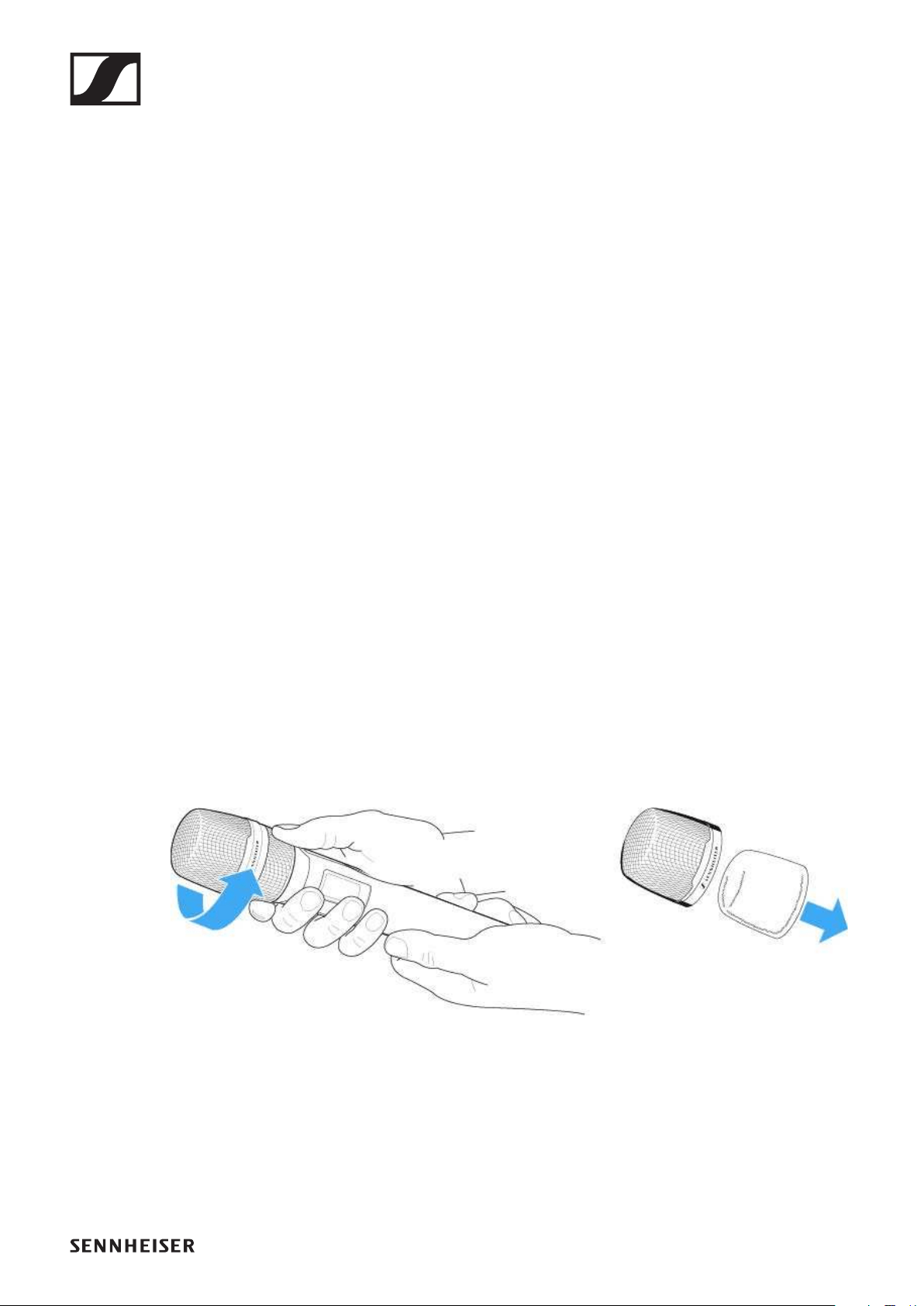
Cleaning and maintenance
253
Cleaning and maintenance
Note the following information when cleaning and maintaining
products of the Evolution Wireless Digital series.
ATTENTION
Liquids can damage the products’ electronics.
Liquids entering the product housing can cause a short-circuit
and damage the electronics.
▷Keep all liquids away from the products.
▷Do not use any solvents or cleansing agents.
▷Disconnect the products from the power supply system
and remove rechargeable batteries and batteries before
you begin cleaning.
▷Clean all products only with a soft, dry cloth.
▷Note the special cleaning instructions below for the follow-
ing products.
Cleaning the sound inlet basket of the microphone
module
▷Unscrew the top sound inlet basket from the microphone
module by turning it counterclockwise.
▷Remove the foam insert.
►
You can clean the sound inlet basket in two ways:
•Use a slightly damp cloth to clean the top sound inlet basket
from the inside and outside.
•Use a brush and rinse with clean water.
▷If necessary, clean the foam insert with a mild detergent or
replace the foam insert.

Cleaning and maintenance
254
▷Dry the top sound inlet basket and foam insert.
▷Reinsert the foam insert.
▷Screw the sound inlet basket back onto the microphone
module.
From time to time, you should also clean the microphone mod-
ule contacts:
▷Wipe the contacts of the microphone module with a soft,
dry cloth.
Clean the transmitter’s contacts.
▷Wipe the contacts with a dry cloth.
Cleaning the L 70 USB and CHG 70N chargers
▷Remove all rechargeable batteries from the charging slots.
▷Disconnect the charger from the power supply system be-
fore cleaning.
▷Clean the product with a dry cloth.
▷In addition, use a brush to remove dust from the charging
slots.
▷Clean the charging contacts from time to time with a cotton
swab, for instance.

Radio and frequencies
256
Radio and frequencies
Why won’t my transmitter synchronize with my receiver?
•Briefly press the SYNC button on both devices, but don’t
press too long („Establishing a radio link | Synchronizing the
receiver and transmitter“)
•The two devices must have the same frequency range („Fre-
quency ranges“)
What is the transmission range of the transmitter?
•Up to 100 m in an ideal environment (without obstacles)
What is the best way to wear the bodypack transmitter?
•Do not kink, bend or cover the antenna
•Avoid skin contact with the antenna
•If possible, attach it to your clothing with the belt clip
How do I know which transmitter is coupled to which re-
ceiver?
•EW-D SKM-S: „Identifying the paired receiver (Identify
function)“
•EW-D SK: „Identifying the paired receiver (Identify func-
tion)“
•EW-DX SKM(-S): „Identifying the paired receiver (Identify
function)“
•EW-DX SK (3-PIN): „Identifying the paired receiver (Identify
function)“
•Additional option: use color coding („Using EW-D Color
Coding Sets to label transmission paths“)
How can I distinguish between my wireless links without
displays on the transmitters?
•EW-D SKM-S: „Identifying the paired receiver (Identify
function)“
•EW-D SK: „Identifying the paired receiver (Identify func-
tion)“
•Additional option: use color coding („Using EW-D Color
Coding Sets to label transmission paths“)

Radio and frequencies
257
The transmitter and receiver are synchronized, but there is
no connection.
•Install antennas correctly on the receiver (EW-D EM: „Con-
necting antennas“ | EW-DX EM 2: „Connecting antennas“)
•EW-D: Use the scan function to find a free channel („AUTO
SCAN menu item“) and synchronize the transmitter again
(„Establishing a radio link | Synchronizing the receiver and
transmitter“)
•EW-DX: Using the Auto Setup function, find a free channel
(„Ch 1 / Ch 2 -> Scan / Auto Setup menu item“) and resyn-
chronize the transmitter („Establishing a radio link | Syn-
chronizing the receiver and transmitter“)
The display on the receiver shows radio levels even though
the paired transmitter is not switched on.
•There may be interfering frequencies (e.g. TV channels)
•EW-D: Use the scan function to find a free channel („AUTO
SCAN menu item“) and synchronize the transmitter again
(„Establishing a radio link | Synchronizing the receiver and
transmitter“)
•EW-DX: Using the Auto Setup function, find a free channel
(„Ch 1 / Ch 2 -> Scan / Auto Setup menu item“) and resyn-
chronize the transmitter („Establishing a radio link | Syn-
chronizing the receiver and transmitter“)
Which frequency ranges are available?
•„Frequency ranges“

Audio
258
Audio
Which microphones can I use with my bodypack transmit-
ter?
•EW-D SK: „Connecting a microphone to the bodypack
transmitter“
•EW-DX SK (3-PIN): „Connecting a microphone to the
bodypack transmitter“
Which microphone modules can I use with my handheld
transmitter?
•EW-D SKM-S: „Replacing the microphone module“
•EW-DX SKM(-S): „Replacing the microphone module“
What exactly do the “Gain” and “AF Out” settings do?
•Gain: level of the audio signal coming from the transmitter
(„GAIN menu item“)
•AF Out: level of the audio signal coming out of the receiver
(„AF OUT menu item“)
How do I adjust the settings so that my wireless link has the
same volume as my guitar cable?
•EW-D: Configure unity gain settings under the menu items
GAIN (volume that reaches the receiver from the guitar
through the bodypack transmitter – „GAIN menu item“) and
AF OUT (volume output from the receiver to the guitar am-
plifier – „AF OUT menu item“).
Possible unity gain settings (depending on the level of the in-
coming signal):
▷
AF Out 18 dB | Gain 27 dB
▷AF Out 12 dB | Gain 33 dB
▷AF Out 6 dB | Gain 39 dB

Audio
259
How can I adjust sensitivity on the transmitter?
•EW-D: You cannot make any settings on the transmitter.
You can adjust the level of the signal coming from the trans-
mitter under the GAIN menu item („GAIN menu item“) on
the receiver.
•EW-DX: In addition to the gain that is set in the receiver („Ch
1 / Ch 2 -> Gain menu item“), you can also set the trim on
the transmitter (EW-DX SKM(-S): „Trim menu item“ | EW-
DX SK (3-PIN): „Trim menu item“) to adjust the sensitivity to
the incoming audio signal.
What is the latency?
•1.9 ms
Which audio outputs are available on the receiver?
•XLR-3 and 6.3 mm jack (EW-D EM: „Outputting audio sig-
nals“ | EW-DX EM 2: „Outputting audio signals“)

Usability
260
Usability
Why won’t my transmitter synchronize with my receiver?
•Briefly press the SYNC button on both devices, but don’t
press too long („Establishing a radio link | Synchronizing the
receiver and transmitter“)
•The two devices must have the same frequency range („Fre-
quency ranges“)
Is there a way to check the battery status of the transmitter
other than on the receiver?
•The Check function allows you to check the battery status
on the transmitter.
•EW-D SKM-S: „Checking the battery status of the transmit-
ter (Check function)“
•EW-D SK: „Checking the battery status of the transmitter
(Check function)“
How do I know if my transmitter is switched on?
•The transmitter’s LINK LED lights up.
•EW-D SKM-S: „Meaning of the LEDs“
•EW-D SK: „Meaning of the LEDs“
•EW-DX SKM(-S): „Meaning of the LEDs“
•EW-DX SK (3-PIN): „Meaning of the LEDs“
My LINK LED is steady or flashing yellow. What does that
mean?
•EW-D EM: „Meaning of the LEDs“
•EW-D SKM-S: „Meaning of the LEDs“
•EW-D SK: „Meaning of the LEDs“
•EW-DX EM 2: „Meaning of the LEDs“
•EW-DX SKM(-S): „Meaning of the LEDs“
•EW-DX SK (3-PIN): „Meaning of the LEDs“

Usability
261
My LINK LED is steady or flashing red. What does that
mean?
•EW-D EM: „Meaning of the LEDs“
•EW-D SKM-S: „Meaning of the LEDs“
•EW-D SK: „Meaning of the LEDs“
•EW-DX EM 2: „Meaning of the LEDs“
•EW-DX SKM(-S): „Meaning of the LEDs“
•EW-DX SK (3-PIN): „Meaning of the LEDs“
Can I also operate an EW-D with desktop applications such
as WSM or Control Cockpit?
•No, that is not possible.
Can I also operate an EW-DX with desktop applications
such as WSM or Control Cockpit?
•Yes, the EW-DX can be operated with WSM and the Control
Cockpit („Connecting receivers in a network“).
Is the EW-D Smart Assist app necessary to operate my de-
vices?
•No, every device can also be operated without the EW-D
Smart Assist app. However, the app offers certain advan-
tages (see „EW-DP 835 | Handheld Set“).
Can the transmitter and receiver connect to other Blue-
tooth-capable systems?
•A Bluetooth connection be only be established between a
receiver and a smartphone with the EW-D Smart Assist app
installed.
How can I turn on my transmitter without it transmitting
immediately?
•Press and hold the SYNC button and then short-press the
ON/OFF button (EW-D SKM-S: „Product overview“ / EW-D
SK: „Product overview“)

Usability
262
Can the ew G4 and EW-D series be operated together?
•The products in the ew G4 and EW-D series are not com-
patible with each other. However, you can operate the two
series in parallel without any problems.
Are the receivers and transmitters of the EW-D and EW-DX
series compatible?
•„Information on compatibility between EW-D, EW-DX and
EW-DP“
How can I distinguish between my wireless links without
displays on the transmitters?
•EW-D SKM-S: „Identifying the paired receiver (Identify
function)“
•EW-D SK: „Identifying the paired receiver (Identify func-
tion)“
•Additional option: use color coding („Using EW-D Color
Coding Sets to label transmission paths“)
What exactly do the “Gain” and “AF Out” settings do?
•Gain: Level of the audio signal coming from the transmitter
(EW-D EM: „GAIN menu item“ | EW-DX EM 2: „Ch 1 / Ch 2 -
> Gain menu item“)
•AF Out: Level of the audio signal coming from the receiver
(EW-D EM: „AF OUT menu item“ | EW-DX EM 2: „Ch 1 / Ch
2 -> AF Out menu item“)
What is the meaning of the Bluetooth icon on the receiver’s
display?
•The receiver is paired to a smartphone, so you can make
settings via the EW-D Smart Assist app.
•„Displays on the receiver’s display panel“
•„EW-DP 835 | Handheld Set“
I don’t want a smartphone to have access to my receiver.
•Disconnect the Bluetooth pairing in your smartphone’s
menu.

Usability
263
What is the best way to wear the bodypack transmitter?
•Do not kink, bend or cover the antenna
•Avoid skin contact with the antenna
•If possible, attach it to your clothing with the belt clip
Can you rotate the bodypack transmitter’s belt clip so that
the antenna points downward?
•Yes, see „Changing the belt clip“

Accessories
264
Accessories
Which microphones can I use with my bodypack transmit-
ter?
•EW-D SK: „Connecting a microphone to the bodypack
transmitter“
•EW-DX SK (3-PIN): „Connecting a microphone to the
bodypack transmitter“
Which microphone modules can I use with my handheld
transmitter?
•EW-D SKM-S: „Replacing the microphone module“
•EW-DX SKM(-S): „Replacing the microphone module“
Which batteries can I use for my transmitter?
•2 x AA 1.5 V
or
•Sennheiser BA 70 rechargeable battery („BA 70 recharge-
able battery and L 70 USB charger“)
•EW-D SKM-S: „Inserting and removing the batteries/re-
chargeable batteries“
•EW-D SK: „Inserting and removing the batteries/recharge-
able batteries“
•EW-DX SKM(-S): „Inserting and removing the batteries/re-
chargeable batteries“
•EW-DX SK (3-PIN): „Inserting and removing the batteries/
rechargeable batteries“
Can I use accessories that I already have from other micro-
phone series?
•You can use passive devices without a power supply (e.g.
AD 1800 or A 1031-U antennas).
•You may already have compatible microphones or micro-
phone modules:
•EW-D SK: „Connecting a microphone to the bodypack
transmitter“
•EW-DX SK (3-PIN): „Connecting a microphone to the
bodypack transmitter“
•EW-D SKM-S: „Replacing the microphone module“
•EW-DX SKM(-S): „Replacing the microphone module“
•We always recommend using the accessories that are opti-
mized for the EW-D: „Accessories“.
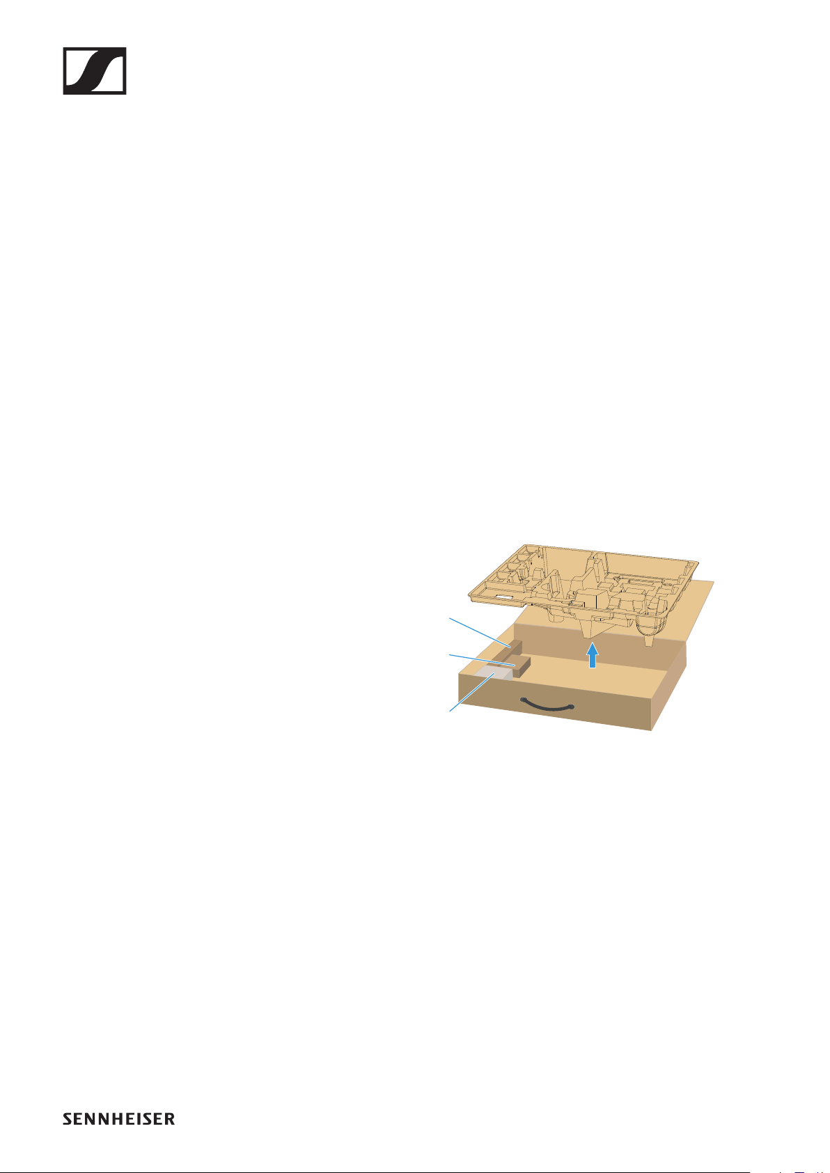
Accessories
265
Which antennas can I use with my receiver?
•In principle, you can use all antennas with BNC connectors
that cover the frequency ranges of the EW-D series („Fre-
quency ranges“)
•Recommended: „Antennas“
What are the advantages of the Half Wave Dipole rod an-
tennas (available as accessories) compared to the shorter
rod antennas included with delivery?
•The Half Wave Dipole rod antennas have a higher antenna
gain and therefore provide greater transmission range in
low-scatter and low-reflection environments („Rod anten-
nas“).
My set is missing the power supply unit and the rack
mounting bracket.
•Take out the packaging insert:
►
Rack mount angles
Power supply unit
Power supply adapters

EW-D Smart Assist app
266
EW-D Smart Assist app
Is the EW-D Smart Assist app necessary to operate my de-
vices?
•No, every device can also be operated without the EW-D
Smart Assist app. However, the app offers certain advan-
tages (see „EW-DP 835 | Handheld Set“).
I want to see if the app is right for me before registering.
Where can I get more information?
•In the app’s demo mode or on the website:
https://www.sennheiser.com/evolution-wireless-digital-app
In which languages is the app available?
•English
•German
•French
•Spanish
•Portuguese
•Russian
•Chinese
•Korean
•Arabic
Can I pair multiple smartphones with a single receiver?
•No, you can pair only one smartphone with the receiver.
How many devices can I operate with my app?
•Up to 16 channels
How do I create a setup with 2 or more devices?
•Use the Add Device and Auto Scan functions. The app will
lead you step by step through the process.

EW-D Smart Assist app
267
Can I set a specific frequency range for the Auto Scan func-
tion?
•No, the function scans the entire available frequency spec-
trum.
Why can’t I access a receiver?
•The receiver may be switched off or out of Bluetooth range.
How are the app and the receivers connected to the app se-
cured against possible misuse?
•To pair a receiver and a smartphone, both devices must be
physically present. Only after successful pairing can values
in the receiver be changed via the smartphone.
Can I use a Bluetooth dongle to operate the app on a com-
puter?
•No. The app is only available for iOS and Android.
How can I display the app on a larger screen?
•You can use a mirroring service such as QuickTime. Howev-
er, you still control the app from the smartphone.
268
SPECIFICATIONS
„System“
„EW-D EM rack receiver“
„EW-DX EM 2 rack receiver“
„EW-D SKM-S handheld transmitter“
„EW-DX SKM | EW-DX SKM-S handheld transmitter“
„EW-D SK bodypack transmitter“
„EW-DX SK | EW-DX SK 3-PIN bodypack transmitter“
„EW-DP EK portable receiver“
„EW-D ASA antenna splitter“
„EW-D AB antenna booster“
„ADP UHF passive directional antenna (470 – 1075 MHz)“

System
270
System
Audio link frequency ranges for EW-D, EW-DP
•Q1-6: 470.2 – 526 MHz
•R1-6: 520 – 576 MHz
•R4-9: 552 – 607.8 MHz
•S1-7: 606.2 – 662 MHz
•S4-7: 630 – 662 MHz
•S7-10: 662 – 693.8 MHz
•U1/5: 823.2 – 831.8 MHz & 863.2 – 864.8 MHz
•V3-4: 925.2 – 937.3 MHz
•Y1-3: 1785.2 – 1799.8 MHz
Audio-Link EW-DX frequency ranges
•Q1-9: 470.2 – 550 MHz
•R1-9: 520 – 607.8 MHz
•S1-10: 606.2 – 693.8 MHz
•S2-10: 614.2 – 693.8 MHz
•S4-10: 630 – 693.8 MHz
•U1/5: 823.2 – 831.8 MHz & 863.2 – 864.8 MHz
•V3-4: 925.2 – 937.3 MHz
•V5-7: 941.7 – 951.8 MHz & 953.05 – 956.05 MHz & 956.65 –
959.65 MHz
•Y1-3: 1785.2 – 1799.8 MHz
Bluetooth® Low Energy (BLE) frequency range
2402 – 2480 MHz
Audio frequency response
20 Hz – 20 kHz (-3 dB) @ 3 dBfs
Audio THD
≤ -60 dB for 1 kHz @ -3 dBfs input level
Dynamic range
134 dB
System latency
1.9 ms

System
271
Operating temperature range
-10 °C – +55 °C (EW-D, EW-DP)
-10 °C – +50 °C (EW-DX)
Relative humidity
5 – 95% (non-condensing)

EW-D EM rack receiver
272
EW-D EM rack receiver
Input voltage
DC 11 – 13 V
Input current
≤ 300 mA
Transmission power
BLE: max. 10 mW EIRP
Audio output power
18 dBu max.
Dimensions
212 × 44 × 189 mm (1 3/4" x 3 7/8" x 7 3/16")
Weight
Approx. 1000 g (without antennas and power supply unit)

EW-DX EM 2 rack receiver
273
EW-DX EM 2 rack receiver
Input voltage
DC 11 – 13 V or PoE IEEE 802.3af Class 0 (CAT5e or higher)
Input current
≤ 1 A
Transmission power
BLE: max. 10 mW EIRP
Audio output power
18 dBu max.
Headphone output
2x 70 mW @ 32 ?
Ethernet
RJ-45 socket, IEEE802.3
100Base-TX (half+full duplex)
10Base-T (half+full duplex)
(CAT5e or higher)
Dimensions
212 × 44 × 206 mm (1 3/4" x 3 7/8" x 7 3/16")
Weight
Approx. 1000 g (without antennas and power supply unit)

EW-D SKM-S handheld transmitter
274
EW-D SKM-S handheld transmitter
Input voltage
2.0 – 4.35 V
Input current
< 300 mA
Power supply
2 AA batteries 1.5 V (alkali manganese) or BA 70 rechargeable
battery pack
Occupied bandwidth
200 kHz
Transmission power
•Audio link: 10 mW ERP (Range Y1-3: 12 mW ERP)
•BLE: max. 10 mW EIRP
Dimensions (diameter x length)
50 x 268 mm (incl. MMD 835 microphone module)
Weight (without batteries)
•Approx. 304 g (incl. MMD 835 microphone module)
•Approx. 195 g (without microphone module)

EW-DX SKM | EW-DX SKM-S handheld transmitter
275
EW-DX SKM | EW-DX SKM-S handheld
transmitter
Input voltage
2.0 – 4.35 V
Input current
< 300 mA
Power supply
2 AA batteries 1.5 V (alkali manganese) or BA 70 rechargeable
battery pack
Occupied bandwidth
200 kHz
Transmission power
•Audio link: 10 mW ERP (Range Y1-3: 12 mW ERP)
•LD mode: 10 mW ERP
•BLE: max. 10 mW EIRP
Dimensions (diameter x length)
•50 x 268 mm (incl. MMD 835 microphone module)
•40 x 200 mm (without microphone module)
Weight (without batteries)
•Approx. 304 g (incl. MMD 835 microphone module)
•Approx. 195 g (without microphone module)

EW-D SK bodypack transmitter
276
EW-D SK bodypack transmitter
Input voltage
2.0 – 4.35 V
Input current
< 300 mA
Power supply
2 AA batteries 1.5 V (alkali manganese) or BA 70 rechargeable
battery pack
Occupied bandwidth
200 kHz
Transmission power
•Audio link: 10 mW ERP (Range Y1-3: 12 mW ERP)
•BLE: max. 10 mW EIRP
Dimensions
63 x 80 x 20 mm (without antennas)
Weight (without batteries)
Approx. 120 g

EW-DX SK | EW-DX SK 3-PIN bodypack transmitter
277
EW-DX SK | EW-DX SK 3-PIN bodypack
transmitter
Input voltage
2.0 – 4.35 V
Input current
< 300 mA
Power supply
2 AA batteries 1.5 V (alkali manganese) or BA 70 rechargeable
battery pack
Occupied bandwidth
200 kHz
Transmission power
•Audio link: 10 mW ERP (Range Y1-3: 12 mW ERP)
•LD mode: 10 mW ERP
•BLE: max. 10 mW EIRP
Dimensions
63.5 x 85 x 20 mm (without antennas)
Weight (without batteries)
approx. 115 – 120 g

EW-DP EK portable receiver
278
EW-DP EK portable receiver
Input voltage
~ 1.8 – 4.35 V
Input current
Typically < 250 mA / max. < 400 mA / max. < 750 mA
(2x AA batteries) < 300 mA @ 5 V (USB-C standalone)
Power supply
2x AA batteries 1.5 V or USB-C PD (max.):
•5 V/1500 mA
•9 V/900 mA
•12 V/700 mA
Transmission power
BLE: max. 10 mW EIRP
Audio output power
< 2 dBV max. (high level) /
< 4 dBV max. (high level)
Headphone output
< 50 mW into 16 ohms
Dimensions
86 × 67 × 28 mm (1 3/4" x 3 7/8" x 7 3/16")
Weight
approx. 140 g

EW-D ASA antenna splitter
279
EW-D ASA antenna splitter
Frequency ranges
•EW-D ASA (Q-R-S): 470 – 694 MHz
•EW-D ASA CN/ANZ (Q-R-S): 470 – 694 MHz
•EW-D ASA (T-U-V-W): 694 – 1075 MHz
•EW-D ASA (X-Y): 1350 – 1805 MHz
EW-D ASA antenna splitter
2 x 1:4 or 1 x 1:8, active
Gain
•in A – out A: 0 ± 1 dB
•in A – out A1 ... A4: 0 ± 1 dB
•in B – out B1 ... B4: 0 ± 1 dB
IIP3
> 25 dBm
Impedance
50 ?
Reflection loss
10 dB (all RF outputs)
Operating voltage
DC +12 V from NT 12-35 CS power supply unit
Current consumption
210 mA
Total current consumption
max. 3 A (with 4 EW-D EM and connected EW-D AB)

EW-D ASA antenna splitter
280
Supply for antenna boosters at ANT RF in A and ANT RF in B
•DC 12 V
•320 mA
Supply for receivers at A1 to A4
•DC 12 V
•Typically 350 mA, max. 500 mA
Relative humidity
5 – 95%
Operating temperature range
-10 °C – +55 °C (14 °F – 131 °F)
Storage temperature range
-20 °C – +70 °C (-4 °F – 158 °F)
Dimensions
Approx. 212 x 168 x 43 mm
Weight
Approx. 1100 g
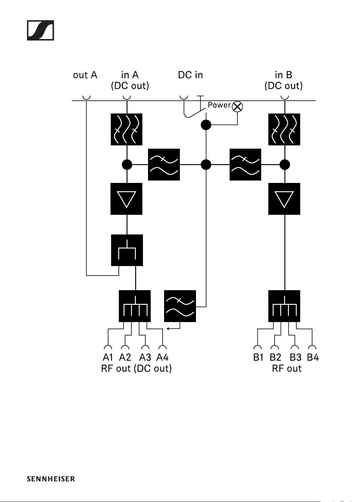
EW-D ASA antenna splitter
281
Block diagram

EW-D AB antenna booster
282
EW-D AB antenna booster
Frequency ranges
•EW-D AB (Q): 470 – 550 MHz
•EW-D AB (R): 520 – 608 MHz
•EW-D AB (S): 606 – 694 MHz
•EW-D AB (U): 823 – 865 MHz
•EW-D AB (V): 902 – 960 MHz
•EW-D AB (Y): 1785 – 1805 MHz
Power supply (DC coupled)
DC 12 V (DC 9 – 18 V) / max. 160 mA @12 V, center contact +
IIP3
> 25 dBm
Max. RF input power
+10 dBm
Gain
Typically 12 dB
Impedance
50 ?
Connections
2x BNC female, DC power supply from OUT to ANT
Dimensions
Approx. 95 x 47 x 21 mm
Weight
Approx. 120 g
Operating temperature range
-10 °C – +55 °C (14 °F – 131 °F)

EW-D AB antenna booster
283
Storage temperature range
-20 °C – +70 °C (-4 °F – 158 °F)
Relative humidity
5 – 95%

ADP UHF passive directional antenna (470 – 1075 MHz)
284
ADP UHF passive directional antenna
(470 – 1075 MHz)
Frequency range
470 – 1075 MHz
Apex angle (-3 dB)
Approx. 100°
Front-to-back ratio
> 14 dB
Gain
Typically 5 dBi
Impedance
50 ?
Connection
BNC female, no DC path
Threads for tripod mounting
3/8" and 5/8"
Dimensions
319 × 310 mm
Weight
Approx. 320 g
Operating temperature range
-10 °C – +55 °C (14 °F – 131 °F)
Storage temperature range
-20 °C – +85 °C (-4 °F – 158 °F)
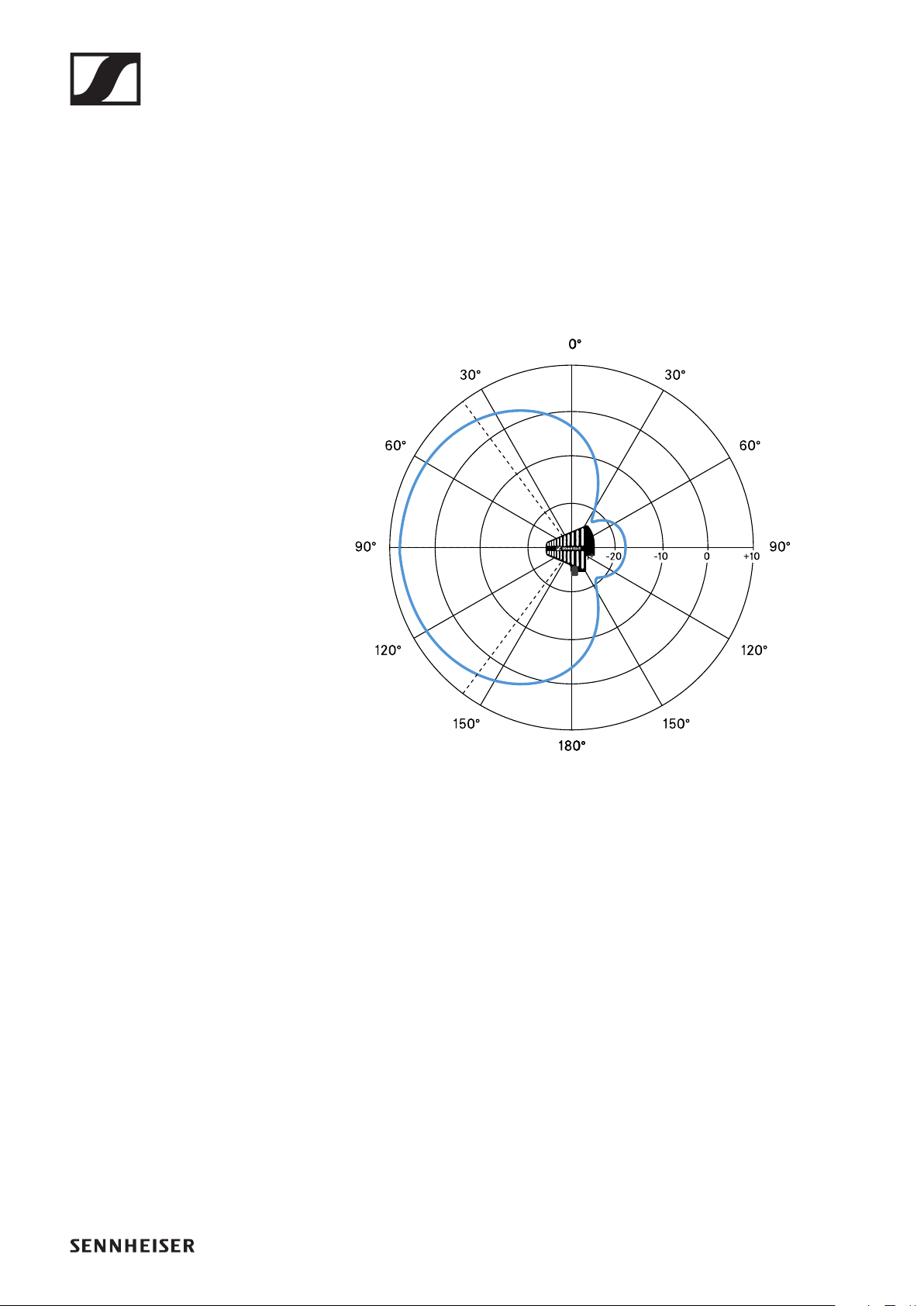
ADP UHF passive directional antenna (470 – 1075 MHz)
285
Relative humidity
5 – 95%
Typical polar diagram
►

BA 70 rechargeable battery
286
BA 70 rechargeable battery
Rated capacity
1720 mAh
Nominal voltage
3.8 V
Charging voltage
max. 4.35 V
Charging time
Typically 3 h @ room temperature
Dimensions
Approx. 54 x 30 x 15
Weight
Approx. 33 g
Temperature range
•Charging: 0 °C – +55 °C (32 °F – 131 °F)
•Discharging: -10 °C – +55 °C (14 °F – 131 °F)
•Storage: -10 °C – +45 °C (14 °F – 113 °F)
Relative humidity
•Charging/discharging: 25 to 95%, non-condensing
•Storage: 30 to 70%, non-condensing

L 70 USB charger
287
L 70 USB charger
Charging capacity
2 Sennheiser BA 70 rechargeable battery packs
Input voltage
Typically 5 V
Input current
max. 2 A
Charging voltage
nominally 4.35 V
Charging current
max. 860 mA per battery pack
Charging time
max. 3.5 h with NT 5-20 UCW power supply unit
Temperature range
•Charging: 0 °C – +55 °C (14 °F – 113 °F)
•Storage: -20 °C – +70 °C (14 °F – 113 °F)
Relative humidity
max. 95% (non-condensing)
Dimensions
100 × 35 × 70 mm (1 3/4" x 3 7/8" x 7 3/16")
Weight
Approx. 86 g

CHG 70N charger
288
CHG 70N charger
Power supply
DC 12 V
or
PoE IEEE 802.3af Class 0 (CAT5e or higher)
Current consumption
max. 3.5 A
Ethernet
RJ-45 socket, IEEE802.3
100Base-TX (half+full duplex)
10Base-T (half+full duplex)
Dimensions
Approx. 200 x 104 x 116 mm
Weight
approx. 640 g
Charging slots
2
Charging capacity per slot
BA 70 rechargeable battery
or
EW-DX SK with BA 70
or
EW-DX SKM with BA 70
Charging voltage
4.35 V

CHG 70N charger
289
Charging current
min. 344 mA
max. 860 mA
Full charging time
Max. 3.5 h
Temperature range
•Charging: -10 °C to +50 °C
•Storage: -20 °C to +70 °C
Relative humidity
max. 95% (non-condensing)