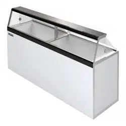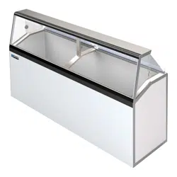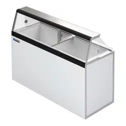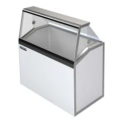
IHC SERIES
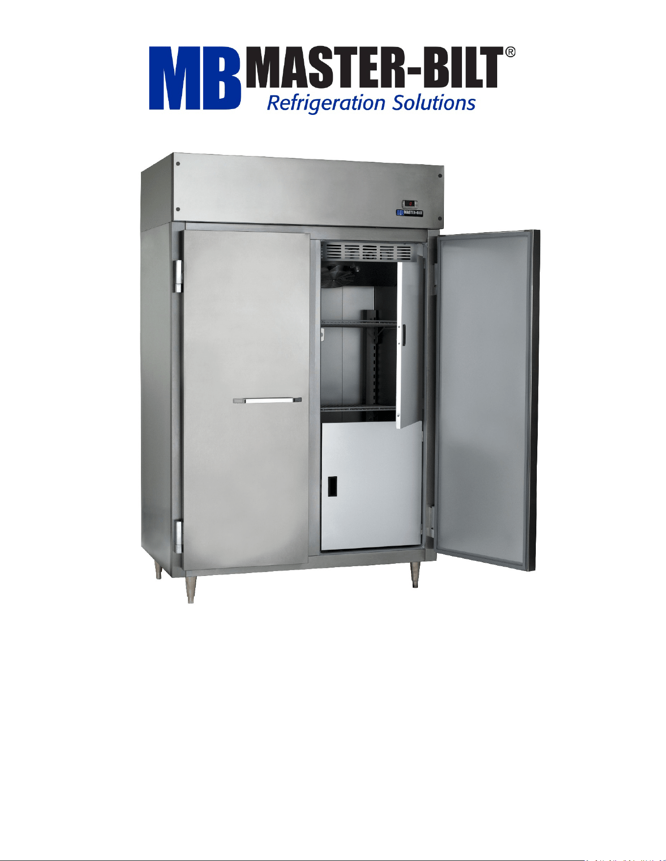
Ice Cream Hardening and Holding Cabinets
Installation & Operations Manual
Master-Bilt Products
908 Highway 15 North
New Albany, MS 38652
800-388-5253
rsgservice@refsg.com

57-02699- Rev. A All specifications within this publication subject to change without notice. © 2025 Master-Bilt Products, LLC. All rights reserved
2
CONTENTS
INTRODUCTION ............................................................................................................................................................ 3
WARNING LABELS AND SAFETY INSTRUCTIONS .......................................................................................................... 4
PRE-INSTALLATION INSTRUCTIONS .............................................................................................................................. 5
Inspection for Shipping Damage ..................................................................................................................... 5
INSTALLATION INSTRUCTIONS ..................................................................................................................................... 5
General Instructions ....................................................................................................................................... 5
Mechanical ..................................................................................................................................................... 5
Electrical ......................................................................................................................................................... 6
Maintaining Your Equipment .......................................................................................................................... 6
Power Cords ................................................................................................................................................... 6
LEG AND CONDENSATE PAN INSTALLATION ................................................................................................................ 7
SERVICE INSTRUCTIONS ............................................................................................................................................... 7
Temperature Probe, Drain Pan Defrost Heater, Drain Line Heater and Fan Motor Replacement ................... 7
Trouble Shooting Guide ............................................................................................................................................................... 8
ELECTRONIC REFRIGERATION CONTROL ...................................................................................................................... 9
Operation ........................................................................................................................................................ 9
Manual Defrost ............................................................................................................................................... 9
Viewing the Set Point (Box Temperature Cut-Out) ........................................................................................ 9
Changing the Set Point .................................................................................................................................... 9
Parameters ...................................................................................................................................................................................... 10
Alarm Signals ................................................................................................................................................. 10
Electrical Connections ................................................................................................................................... 10
FINAL CHECK LIST ........................................................................................................................................................ 10
MASTER-BILT PART LIST ............................................................................................................................................. 11
ACCESSORIES .............................................................................................................................................................. 11
SALE AND DISPOSAL ................................................................................................................................................... 11
IHC-27 WIRING DIAGRAM .......................................................................................................................................... 12
IHC-48 WIRING DIAGRAM .......................................................................................................................................... 13
57-02699- Rev. A All specifications within this publication subject to change without notice. © 2025 Master-Bilt Products, LLC. All rights reserved
3
INTRODUCTION
Thank you for purchasing a Master-Bilt
cabinet. This manual contains important instructions for installing, using,
and servicing a Master-Bilt IHC ice cream hardening and holding cabinet. A parts list is included with this manual.
Read all these documents carefully before installing or servicing your equipment.
STORE CONDITIONS
IHC models are designed to operate in the controlled environment of an air-conditioned store. The store
temperature should be at or below 75°F and a relative humidity of 55% or less. At higher temperature or humidity
conditions, the performance of these cases may be affected and the capacity diminished.
The cabinet should not be positioned where it is directly exposed to rays of sun or near a direct source of radiant
heat or airflow. This will adversely affect the case and will result in poor performance.
If this cabinet is to be located against a wall, there should be at least 4-inch space between the wall and the back
of the cabinet. This space will allow for air circulation behind the cabinet which will prevent condensation on the
exterior surfaces.
NOTICE
Read this manual before installing your cabinet. Keep the manual and refer to it before doing any
service on the equipment. Failure to do so could result in personal injury or damage to the cabinet.
DANGER
Risk of fire or explosion. Flammable refrigerant used. Consult installation/operations manual before
attempting to install or service this product. All safety precautions must be followed.
NEVER use an extension cord to power these units. All electrical wiring hook-ups must be done in
accordance with all applicable local, regional or national standards.
DANGER
Improper or faulty hook-up of electrical components on the refrigeration units can result in severe injury
or death.
NEVER use an extension cord to power these units. All electrical wiring hook-ups must be done in
accordance with all applicable local, regional or national standards.
NOTICE
Installation and service of the refrigeration and electrical components of the cabinet must be performed
by a refrigeration mechanic and/or a licensed electrician.
The portions of this manual covering refrigeration and electrical components contain technical instructions
intended only for people qualified to perform refrigeration and electrical work. This manual cannot cover every
installation, use or service situation. If you need additional information, please contact our service department at
57-02699- Rev. A All specifications within this publication subject to change without notice. © 2025 Master-Bilt Products, LLC. All rights reserved
4
WARNING LABELS AND SAFETY INSTRUCTIONS
DANGER
Risk of fire or explosion. Flammable refrigerant used. To be repaired only by trained service personnel.
Do not puncture refrigerant tubing.
CAUTION
Risk of fire or explosion. Flammable refrigerant used. Consult installation/operations manual before
attempting to install or service this product. All safety precautions must be followed.
NOTICE
Installation and service of the refrigeration and electrical components of the cabinet must be
performed by a refrigeration mechanic and/or a licensed electrician
NOTICE TO EMPLOYERS
You must make sure that everyone who installs, uses or services your cabinet is thoroughly familiar
with all safety information and procedures.
Important safety information is presented in this section and throughout the manual. The following signal words
are used in the warnings and safety messages:
• DANGER: Severe injury or death will occur if you ignore the message.
• WARNING: Severe injury or death can occur if you ignore the message.
• CAUTION:
Minor injury or damage to your cabinet can occur if you ignore the message.
• NOTICE: This is important installation, operation or service information. If you ignore the message, you may
damage your cabinet.
The warning and safety labels shown throughout this manual are placed on your Master-Bilt cabinet at the
factory. Follow all warning label instructions. If any warning or safety labels become lost or damaged, contact us
at 800-388-5253 or rsgservice@refsg.com for replacements.
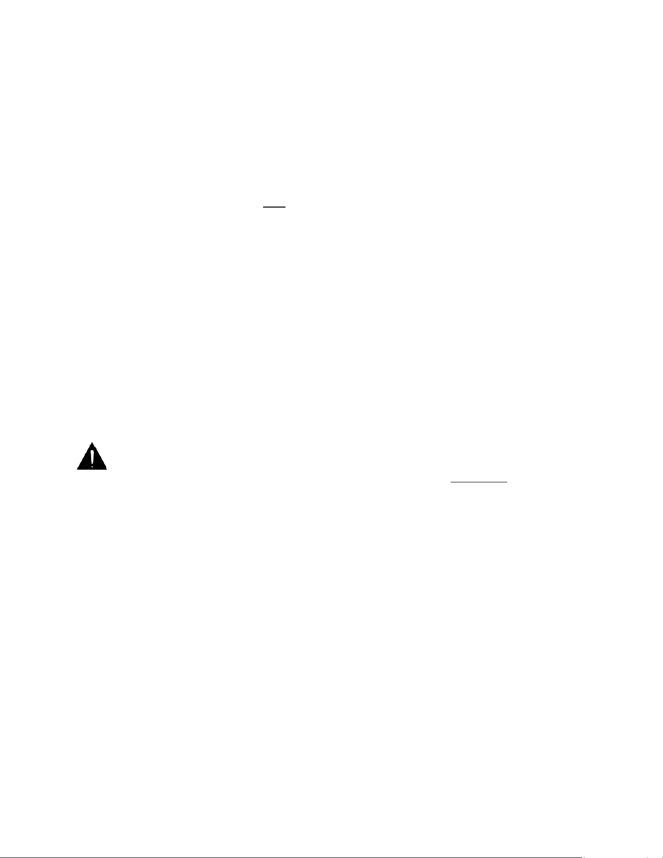
This label is attached to the cabinet power cord
57-02699- Rev. A All specifications within this publication subject to change without notice. © 2025 Master-Bilt Products, LLC. All rights reserved
5
PRE-INSTALLATION INSTRUCTIONS
INSPECTION FOR SHIPPING DAMAGE
You are responsible for filing all freight claims with the delivering truck line. Inspect all cartons and crates for
damage as soon as they arrive. If damage is noted to shipping crates or cartons or if a shortage is found, note this
on the bill of lading (all copies) prior to signing.
If damage is discovered when the cabinet is uncrated, immediately call the delivering truck line and follow up the
call with a written report indicating concealed damage to your shipment. Ask for an immediate inspection of your
concealed damage item. Crating material must be retained to show the inspector from the truck line.
INSTALLATION INSTRUCTIONS
GENERAL INSTRUCTIONS
•
Be sure the equipment is properly installed by competent service agents.
•
Keep the equipment clean and sanitary so it will meet your local sanitation codes. Clean the cabinet with a mild
detergent and water, then rinse.
•
Rotate your stock so that older stock does not accumulate. This is especially important for ice cream. A "First-In,
First-Out" rotation practice will keep the products in good salable condition.
•
Do not place product in the cabinet when it is soft or partially thawed. Also, product should not be placed in the
cabinet for at least six hours after it is started.
•
Stock the cabinet as quickly as possible, exposing only small product quantities to store temperatures for short
periods of time.
NOTICE TO STORE OWNERS / MANAGERS
Moisture or liquid around or under the cabinet is a potential slip/fall hazard for persons walking by or
working in the general area of the cabinet. Any cabinet malfunction or housekeeping problem that
creates a slip/fall hazard around or under the cabinet should be corrected immediately.
If moisture or liquid is observed around or under the cabinet, an immediate investigation should be made
by qualified personnel to determine the source of the moisture or liquid. The investigation should
determine if the cabinet is malfunctioning or if there is a drainpipe leaking.
MECHANICAL
Remove front grille and check refrigeration lines to ensure they are free (not touching each other or compressor).
Spin the condenser fan blade to make sure it is free.
Remove cabinet from crate base and slide into location. Cabinet must be level from side to side and front to back
for correct draining of coil pan and for self-closing doors to operate correctly. Allow minimum of four inches
between back of cabinet and wall and between top of cabinet and ceiling for proper condensing unit air
circulation.
To comply with sanitation requirements, the cabinet must be mounted on legs (six-inch high minimum) or casters or
the base must be sealed to the floor with an N.S.F. listed silicone sealant.
To comply with UL requirements the cabinet must have a minimum clearance of four inches at the top, six inches at
the rear. No clearance is required on the sides.
57-02699- Rev. A All specifications within this publication subject to change without notice. © 2025 Master-Bilt Products, LLC. All rights reserved
6
ELECTRICAL
WARNING
Before servicing electrical components in the case or the doors or door frames make sure all power to
case is off. Always use a qualified technician.
Check voltage and amps drawn on (Page 17) to determine proper line and fuse or circuit breaker size. Check power
supply for low voltage. If voltage reads “120” with no load, and it drops below “107” when the compressor tries to
start, it is an indication of too small supply wiring or too long to run.
It is recommended that a separate circuit be run for each cabinet to prevent another appliance burning the fuse or
tripping the circuit breaker, causing loss of product.
WARNING
The cabinet must be grounded.
MAINTAINING YOUR EQUIPMENT
Planned Preventative Maintenance (PPM), also referred to as planned maintenance, is a prescheduled
maintenance routine, set out to ensure that your refrigeration equipment is maintained and working efficiently.
Most service companies offer this service, and the frequency of PPM depends on your site conditions. Most PPM
contracts are scheduled monthly, quarterly or annually.
Failure to keep your unit maintained can result in breakdowns and possibly voiding your unit’s warranty.
Here is a list of preventative maintenance items. Some programs vary pending needs and application.
•
Cleaning the condenser coil
•
Clearing the condensate drains
•
Cleaning fan motors and blades
•
Inspecting electrical connections
•
Checking door gaskets
•
Monitoring temperature and cycling
•
Inspecting compressor and start components
•
Logging operational characteristics so they can be compared during future visits.
POWER CORDS
The power cords are rated 15A, 120 volt for the IHC-27 and 20A, 120 V for the IHC-48. Cords are located on top of
the cabinet at the right rear. On initial start-up, the evaporator fan motors will not start and you cannot initiate a
defrost until the evaporator coil temperature has lowered to 25°F. This is due to the thermostat. Also, the cabinet
comes with a non-adjustable “front” control to keep the mullion heaters off until the cabinet temperature has
lowered to 10°F.
57-02699- Rev. A All specifications within this publication subject to change without notice. © 2025 Master-Bilt Products, LLC. All rights reserved
7
LEG AND CONDENSATE PAN INSTALLATION
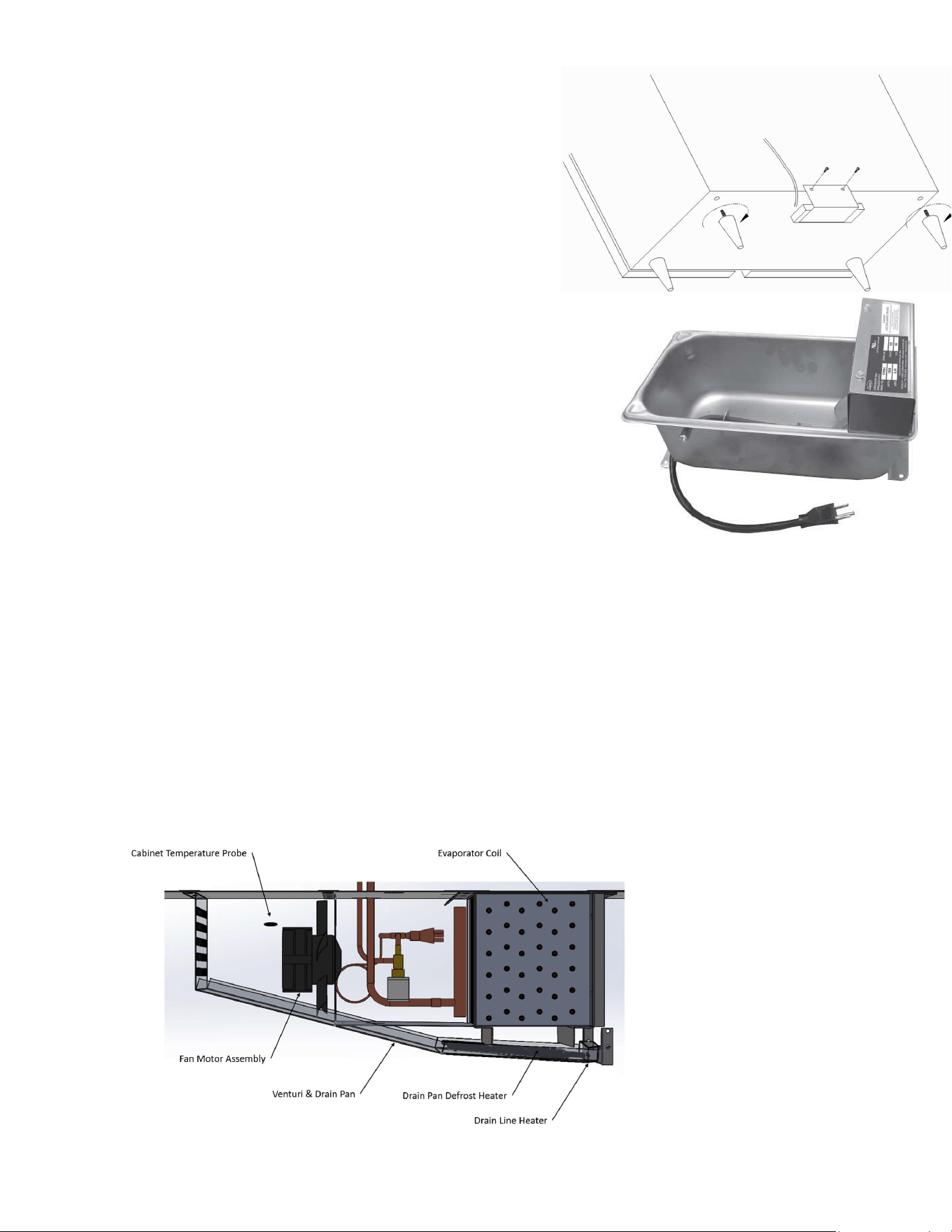
LEG INSTALLATION
Screw legs into existing crate mounting holes.
CONDENSATE HEATER PAN (IF PROVIDED)
Mount pan and bracket assembly to rear of cabinet with 2 large
sheet metal screws (supplied). Be sure pan is located directly
under cabinet drain.
CONDENSATE PAN ASSEMBLY (OPTIONAL)
1.
Place the condensate drain pan (evapoway pan) level
behind or slide under the cabinet.
2.
Route the drain line of the cabinet to the pan so the
water can drip into the pan during defrost.
Do not let the drain tube touch the drain pan’s heater. It can melt the
tube or even catch it on fire.
3.
Plug the drain pan into a separate 115V power supply.
SERVICE INSTRUCTIONS
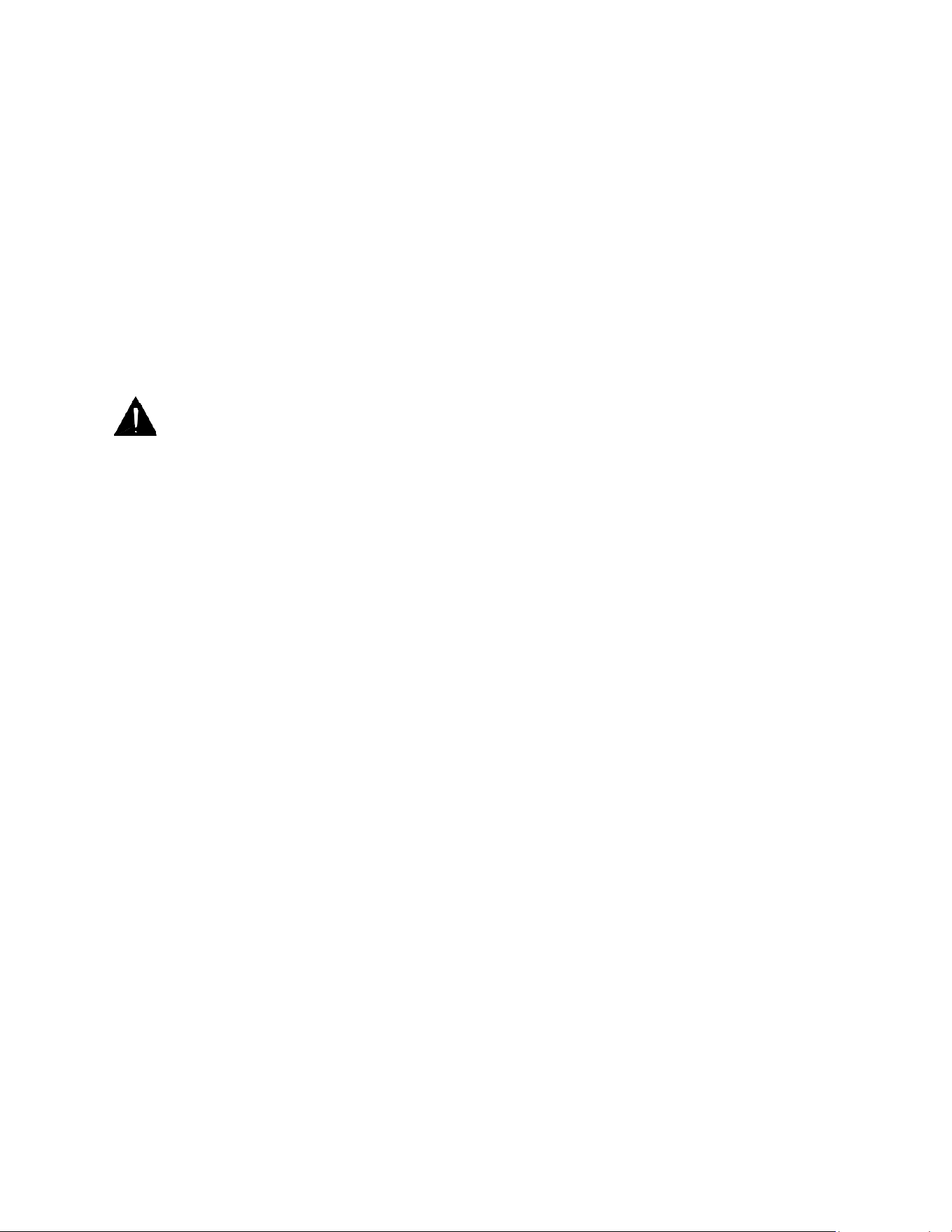
TEMPERATURE PROBE, DRAIN PAN DEFROST HEATER, DRAIN LINE HEATER AND FAN MOTOR
REPLACEMENT
Before servicing the unit or replacing any components, technician must:
1.
Turn the refrigeration rocker switch to the 0 position. This rocker switch is located on top of the cabinet at the
back of the control box behind the temperature controller. Once the switch is turned to the 0 position, remove
the electric power cord from the outlet. Once repairs are completed, do not forget to re-plug the power cord
and return the refrigeration rocker switch to the 1 position.
2.
Remove screws from top front of venturi and drain pan and pull down.
57-02699- Rev. A All specifications within this publication subject to change without notice. © 2025 Master-Bilt Products, LLC. All rights reserved
8
To change a temperature probe, disconnect the sensor wires from the controller and place the new sensor in the
original position. Use plastic tie to tighten the new temperature sensor to the hole in the fan shroud. Make sure the
sensor wires do not touch or are not close to any heater rods. Replace Permagum at the cabinet top penetration as
needed.
To change drain pan defrost heater, remove screws from drain pan and pull down. Disconnect the electrical wires,
then unclip the defective heater from the venturi and drain pan. Reverse the procedure to install the new drain
pan defrost heater.
To change drain drain line heater, remove screws from drain pan and pull down. Then disconnect the electrical
wires and pull the defective heater from the drain line. Reverse the procedure to install the new drain line heater.
To change fan motor, disconnect fan motor leads and screws that attach motor to bracket. Replace the motor and
re-connect leads and screws.
NOTICE
Since this cabinet contains flammable refrigerant, you should only use approved replacement
components. Refer to the part list in this manual for ordering.
It is recommended to stock a small quantity of parts for R290 condensing units (condenser fan motor,
capacitors, condenser fan blade, etc.) for timely manufacturing and field replacements.
TROUBLE SHOOTING GUIDE
1. High head pressure and high back pressure:
A. Condenser coil clogged or restricted
B. Condenser fan motor defective
C. Air discharge in rear of cabinet restricted
2. Low back pressure and low head pressure:
A. Restriction in system
B. Refrigerant undercharged
C. Leak in system
3. Pressure normal but cabinet is warm:
A. Coil blocked with frost (see #4)
B. Refrigerant undercharged
C. Control set too warm
4. Cabinet not cycling, coil blocked with frost:
A. Defective temperature controller
B. Refrigerant overcharged
C. Location too hot
D. Condenser clogged
E. Condenser fan motor defective
F. Defrost heater not operating
5. Compressor starts and runs but cycles on overload:
A. Low voltage
B. Relay defective
C. Overload defective
D. High head pressure
57-02699- Rev. A All specifications within this publication subject to change without notice. © 2025 Master-Bilt Products, LLC. All rights reserved
9
ELECTRONIC REFRIGERATION CONTROL
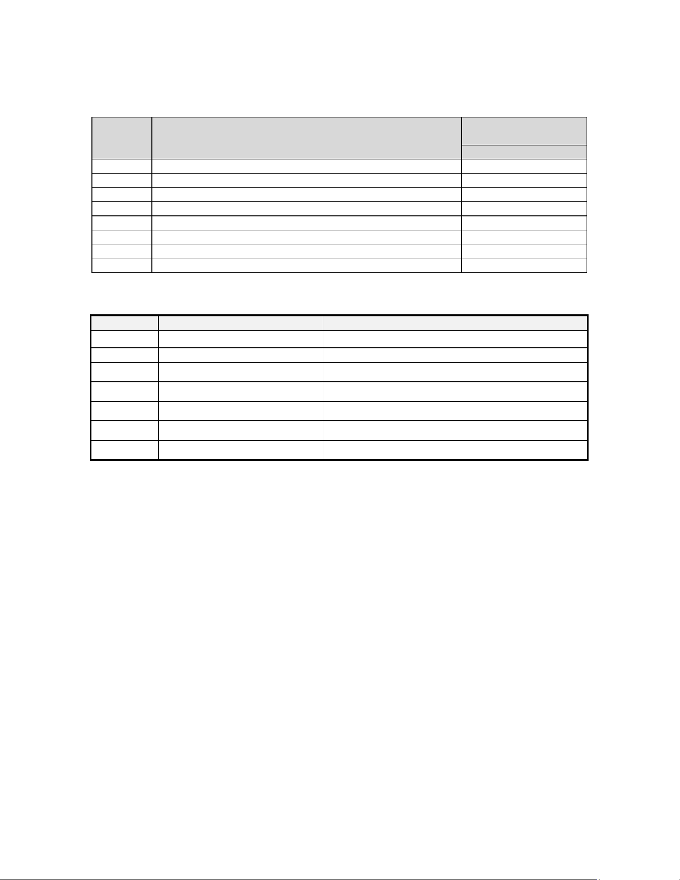
OPERATION
Compressor
When the control is first turned on, the LED indicator under COMP on the display will blink. The cabinet will enter a
defrost at start-up. The compressor(s) and the defrost icon will be on. The defrost will last 6 minutes followed by a
three-minute dripping time. The compressor(s) icons will then be on if the temperature is above set point +7°F.
The evaporator fan(s) Icon will then be on after a two-minute delay. After the initial defrost and between two
consecutive defrosts the compressor(s) and evaporator fan(s) icon will be on when the cabinet temperature is
above set point + 7°F until the temperature drops to the set point. The compressor(s) and fan(s) icon will then be off
until the cabinet temperature rises above set point +7°F. A defrost with the same timing sequence as the initial
defrost will occur every 8 hours.
Fan
If a door is opened when the evaporator fan(s) is on, the fan(s) will be turned off for one minute. After this one-
minute delay the fan will be turned back on, the door open alarm DA will blink on the controller display, and the
alarm will sound.
Defrost
The control uses timed defrost every 8 hours. Scheduled defrost can be bypassed by using the manual defrost
feature of the controller. During scheduled or manual defrost the display will show dEF and the LED indicator
under dF is on.
MANUAL DEFROST
1.
Push this DEFROST key for more than 2 seconds and a manual defrost will start.
2.
While in defrost, Push and hold the DEFROST key for more than 5 seconds and the controller will
end the defrost cycle. The controller will then immediately start the compressor and evaporator fan.
VIEWING THE SET POINT (BOX TEMPERATURE CUT-OUT)
1.
Push and immediately release the SET key: the display will show the Set point value;
2.
Push and immediately release the SET key or wait for 5 seconds to display the probe value (actual box
temperature) again.
CHANGING THE SET POINT
1.
Push the SET key for more than two seconds to change the set point value;
2.
The value of the set point will be displayed and the LED under COMP starts blinking;
3.
To change the Set value push the UP ▲ or DOWN▼ arrows within 10s. To memorize the new set point value
push the SET key again or wait 10 seconds.
NOTE 1: The set value is stored even when the procedure is exited by waiting for the time-out to expire.
NOTE 2: Master-Bilt’s SETPOINT is factory set at a recommended –25°F.
57-02699- Rev. A All specifications within this publication subject to change without notice. © 2025 Master-Bilt Products, LLC. All rights reserved
10
PARAMETERS
Parameters which can be changed in the programming mode, as well as their ranges:
Display
Symbol
Description
Factory’s Setting
SEt
Temperature set point
-25°F
Hy
Cut-out temperature is Set + Hy, Differential
7°F
LS
Minimum Temperature Set Point
-37°F
Us
Maximum Temperature Set Point
32°F
ALU
High Temperature Alarm
30°F
ALL
Low Temperature Alarm
-45°F
Us
High temperature alarm is enabled after a delay
45°F
ALd
Temperature Alarm Delay
30 minutes
ALARM SIGNALS
Message
Cause
Outputs
“P1”
Room probe failure
Compressor output according to par. “Con” and “COF”
“HA”
Maximum temperature alarm
Outputs unchanged.
“LA”
Minimum temperature alarm
Outputs unchanged.
“dA”
Door open
Compressor and fans restarts
“EA”
External Alarm
Output unchanged
“CA”
Serious External alarm(i1F=bAL)
All output off
“CA”
Pressure switch alarm (i1F=PAL)
Outputs unchanged.
Probe alarm “P1” starts some seconds after the fault in the related probe; they automatically stop some seconds
after the probe restarts normal operation. Check connections before replacing the probe.
Temperature alarms “HA” and “LA” automatically stop as soon as the thermostat temperature returns to normal
values and when defrost starts.
ELECTRICAL CONNECTIONS
The controller is provided with screw terminal block or male terminals to connect cables with a cross section up to
2,5 mm
2
. Before connecting cables make sure the power supply complies with the control’s requirements.
Separate the probe cables from the power supply cables, outputs and power connections. Do not exceed the
maximum current allowed on each relay. In case of heavier loads, use a suitable external relay.
FINAL CHECK LIST
•
Check operating pressures
•
Check electrical requirements of unit to supply voltage
•
Set temperature control for desired temperature setting
•
Check to make sure the compressor switch, behind the front grill, is on before starting up the cabinet
•
Check condensing unit for vibrating or rubbing tubing. Dampen and clamp as required.
57-02699- Rev. A All specifications within this publication subject to change without notice. © 2025 Master-Bilt Products, LLC. All rights reserved
11
MASTER-BILT
PART LIST
Use this chart when ordering replacement parts for your IHC cabinet. Always advise cabinet serial number when ordering parts
Description
IHC-27
IHC-48
Compressor
03-15546
03-15546
Run Capacitor
19-14844
19-14844
Start Capacitor (with resistor)
19-14840
19-14840
Compressor Start Relay
19-14836
19-14836
Compressor overload
19-14832
19-14832
Condensate Heater (Option)
17-09412
17-09084
Condenser Coil
01-01970
01-01970
Filter Dryer
09-10656
09-10656
Condenser Fan Guard
25-01414
25-01414
Condenser Fan Blade
15-13166
15-13166
Condenser Fan Motor
13-13456
13-13456
Electronic Controller
19-14814 with 57-02696 prog.
19-14815 with 57-02691 prog.
Cabinet Temperature Sensor
19-14244
19-14244
On/Off switch On Back Of Control Box
19-14810
19-14810
Capillary Tube
11-02010
11-02010
Door Handle
35-01488
35-01488
Door Gasket
37-01207
37-01211
Door Hinge-Inner Doors-L.H.
35-01451
35-01451
Door Hinge-Inner Doors-R.H.
35-01452
35-01452
Door Hinge-Outer Doors
35-01450
35-01450
Door Trim
29-01481
29-01380
Door switch
19-14809
19-14809
Drain Pan Heater
17-09671
17-09672
Evaporator Coil
07-14196
07-14197
Evaporator Fan Motor Assembly
13-13455
13-13455
Hot Gas Evap Defrost Solenoid coil
09-10645
09-10645
Cap Tube Defrost Solenoid Coil
09-10646
09-10646
Relays Inside Control Box
19-14818
19-14818
Heater Safety Control
19-01164
19-01164
Leg
27-00558
27-00558
Shelves (Cantilever)
33-01519
33-01518
High Limit Pressure Switch
09-10649
09-10649
ACCESSORIES
Description
IHC-27
IHC-48
Casters (4) 5” diameter
A297-11140
A297-11140
Tray Slides
9/16” lip ledge for 12” X 20” or 18” X 26” pans (must specify)
A340-21100
1-3/16” bottom ledge for 12” X 20” or 18” X 26” pans
(must specify)
A340-21200
SALE AND DISPOSAL
OWNER RESPONSIBILITY
If you sell or give away your Master-Bilt cabinet, you must make sure that all safety labels and the installation/operations
manual are included with it. If you need replacement labels or manual, Master-Bilt will provide them free of charge. Contact
the customer service department at Master-Bilt at 800-388-5253 or rsgservice@refsg.com.
57-02699- Rev. A All specifications within this publication subject to change without notice. © 2025 Master-Bilt Products, LLC. All rights reserved
12
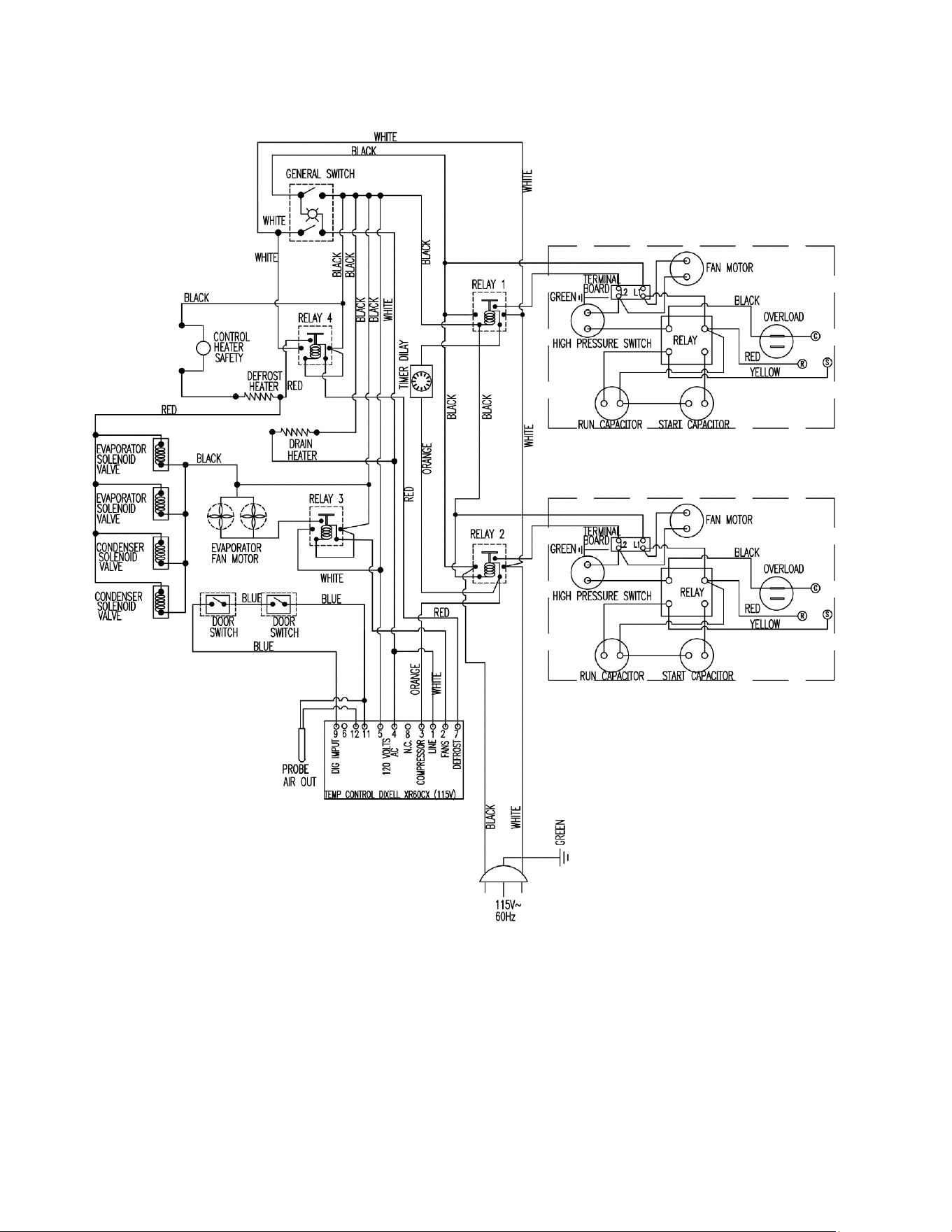
IHC-27 ELECTRICAL DIAGRAM
57-02699- Rev. A All specifications within this publication subject to change without notice. © 2025 Master-Bilt Products, LLC. All rights reserved
13
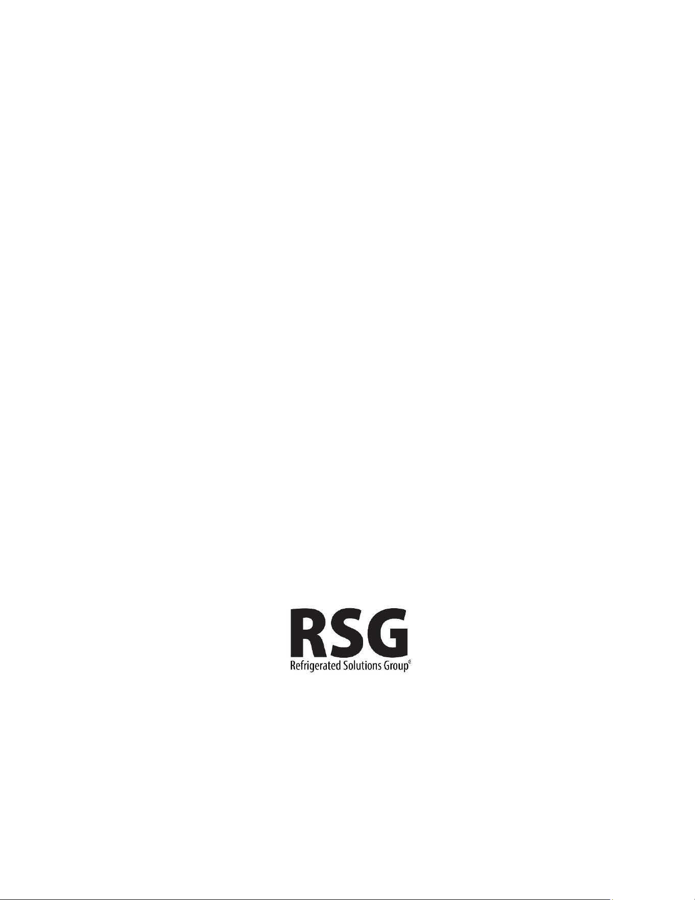
IHC-48 ELECTRIC DIAGRAM

57-02699- Rev. A All specifications within this publication subject to change without notice. © 2025 Master-Bilt Products, LLC. All rights reserved
14

57-02699- Rev. A All specifications within this publication subject to change without notice. © 2025 Master-Bilt Products, LLC. All rights reserved
15
57-02699- Rev. A All specifications within this publication subject to change without notice. © 2025 Master-Bilt Products, LLC. All rights reserved
16
Master-Bilt
908 Highway 15 North
New Albany, MS 38652
800-647-1284 Sales
800-388-5253 Parts/Service