1/6 Rev. 0 57-02680 1
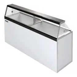
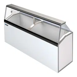
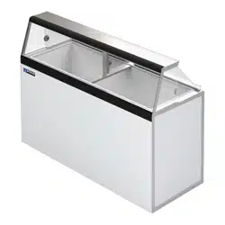
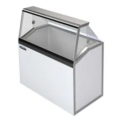
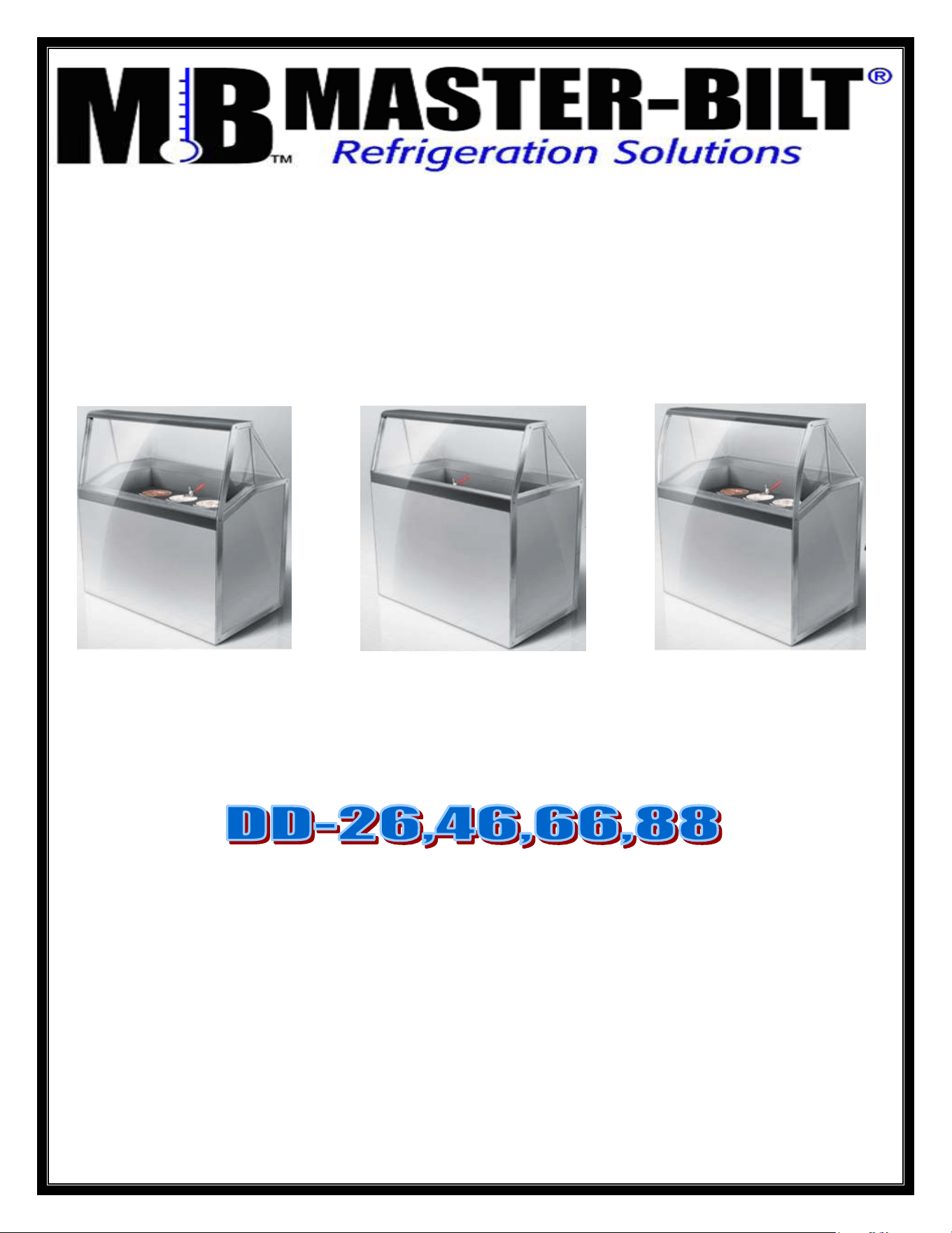
Deluxe Ice Cream Dipping/Display Merchandisers
DD – Standard Model
DD-L – Low Glass Model
DD-LCG – Low Curved Glass Model
R290
Installation & Operations Manual
Master-Bilt Products
908 Highway 15 North
New Albany, MS 38652
Phone: (800) 684-8988

1/6 Rev. 0 57-02680 2
TABLE OF CONTENTS
INTRODUCTION………………………………….…………………………………………………………………... 4
STORE CONDITIONS…………………………….……………….…..…………………………………………….. 4
WARNING LABELS AND SAFETY INSTRUCTIONS………..…..……………………………………………… 5
PRE-INSTALLATION INSTRUCTIONS………………………..…..………………………………….……………6
Inspection for Shipping Damage…………………………………………………………….…………….. 6
INSTALLATION INSTRUCTIONS………………………………………………………………………………….. 7
General Instructions………………………………………………………………………………………….7
Electrical…..………………………………………………………………………………………………….. 7
Mechanical…………………………………………………………………………………………………… 8
Startup………………………………………………………………………………………………………. 8
TEMPERATURE CONTROL…….…………………………………………………………………………………...9~10
CLEANING INSTRUCTIONS…………………………………………………………………………………………11
Can Holder Cleaning………………………………………………………………………………………. 11
Frost Shield Cleaning……………………………….………………………………………………………. 11
OPERATION CONDITIONS AND PRESSURES ……..……………………………………………………….. 12
Trouble Shooting……………………………………………………………………………………………12
SERVICE INSTRUCTIONS………………………………………………………………………………………….. 12
CONTROLLER SENSER PROBE LOCATION…………………………………………………………………….13~15
MASTER-BILT
®
PART NUMBERS……………………………………………………………………………….. 20
ACCESSORIES………………………………………………………………………………………………………..21
SALE AND DISPOSAL………………………………………………………………………………………………. 21
WIRING DIAGRAMS…………………….………………………………………………………………………...22-23

1/6 Rev. 0 57-02680 3
1/6 Rev. 0 57-02680 4
INTRODUCTION
Thank you for purchasing a Master-Bilt
®
cabinet. This manual contains important instructions for installing, using
and servicing a Master-Bilt
®
DD case. A parts list is included in with this manual. Read all these documents
carefully before installing or servicing your equipment.
STORE CONDITIONS
The Master-Bilt
®
DD cases are designed to operate in the controlled environment of an air-conditioned store. The
store temperature should be at or below 75°F and a relative humidity of 55% or less. At higher temperature or
humidity conditions, the performance of these cases may be affected and the capacity diminished. It is not
uncommon in a newly constructed store for the temperature and humidity to be above design conditions. These
excessive conditions may produce sweating in the case until the store is operational and the ambient environment
is more desirable.
The Master-Bilt
®
DD should not be positioned where it is directly exposed to rays of sun or near a direct source of
radiant heat or airflow. This will adversely affect the case and will result in poor performance.
NOTICE
Read this manual before installing your cabinet. Keep the manual and refer to it before doing any service
on the equipment. Failure to do so could result in personal injury or damage to the cabinet.
DANGER
Improper or faulty hook-up of electrical components of the refrigeration units can result in severe injury or
death.
NEVER use an extension cord to power this unit. All electrical wiring hook-ups must be done in
accordance with all applicable local, regional or national standards.
NOTICE
Installation and service of the refrigeration and electrical components of the cabinet must be performed by
a refrigeration mechanic and/or a licensed electrician
The portions of this manual covering refrigeration and electrical components contain technical instructions intended
only for persons qualified to perform refrigeration and electrical work.
This manual cannot cover every installation, use or service situation. If you need additional information have the
serial number at hand and call or write us:
Customer Service Department
Master-Bilt Products
Highway 15 North
New Albany, MS 38652
Phone (800) 684-8988
Fax (800) 684-8988

1/6 Rev. 0 57-02680 5
WARNING LABELS AND SAFETY INSTRUCTIONS
This symbol is used to alert user that there is risk of fire or explosion since flammable refrigerant is
used. This symbol can be observed on back or sides of cabinet.
This symbol is the safety-alert symbol. When you see this symbol on your cabinet or in this
manual, be alert to the potential for personal injury or damage to your equipment.
Be sure you understand all safety messages and always follow recommended precautions and safe operating
practices.
NOTICE TO EMPLOYERS
You must make sure that everyone who installs, uses or services your cabinet is thoroughly familiar with
all safety information and procedures.
Important safety information is presented in this section and throughout this section and throughout the manual.
The following signal words are used in the warnings and safety messages:
DANGER: Severe injury or death will occur if you ignore the message.
WARNING: Severe injury or death can occur if you ignore the message.
CAUTION: Minor injury or damage to your cabinet can occur if you ignore the message.
NOTICE: This is important installation, operation or service information. If you ignore the
message, you may damage your cabinet.
The warning and safety labels shown throughout this manual are placed on your Master-Bilt Products
cabinet at the factory. Follow all warning label instructions. If any warning or safety labels become lost or
damaged, call your customer service department at (800) 684-8988 for replacements.
This label is located on top of the electrical control This label is attached to the cabinet power cord
label and on the wiring channel. on models with a power cord.
CAUTION!
GROUND REQUIRED
FOR SAFE OPERATION

1/6 Rev. 0 57-02680 6
PRE-INSTALLATION INSTRUCTIONS
INSPECTION FOR SHIPPING DAMAGE
You are responsible for filing all freight claims with the delivering truck line. Inspect all cartons and crates for
damage as soon as they arrive. If damage is noted to shipping crates or cartons or if a shortage is found, note this
on the bill of lading (all copies) prior to signing.
If damage is discovered when the cabinet is uncrated, immediately call the delivering truck line and follow up the
call with a written report indicating concealed damage to your shipment. Ask for an immediate inspection of your
concealed damage item. Crating material must be retained to show the inspector from the truck line.
1/6 Rev. 0 57-02680 7
INSTALLATION INSTRUCTIONS
GENERAL INSTRUCTIONS
1. Be sure the equipment is properly installed by competent service people.
2. Keep the equipment clean and sanitary so it will meet your local sanitation codes.
3. Rotate your stock so that older stock does not accumulate. This is especially important for ice
cream. A "First-In, First-Out" rotation practice will keep the products in good salable condition.
4. Do not place product in the case when it is soft or partially thawed. Also, product should not be put in the case
for at least 6 hours after it is started.
5. Stock cases as quickly as possible, exposing only small quantities to store temperatures for short periods of
time.
6. When replacing burned out LED, be sure that the electrical power to the lighting circuit is turned off.
NOTICE TO STORE OWNERS / MANAGERS
Moisture or liquid around or under the cabinet is a potential slip/fall hazard for persons walking by or
working in the general area of the cabinet. Any cabinet malfunction or housekeeping problem that creates
a slip/fall hazard around or under the cabinet should be corrected immediately.
If moisture or liquid is observed around or under a Master-Bilt
®
cabinet, an immediate investigation should be made
by qualified personnel to determine the source of the moisture or liquid. The investigation should determine if the
cabinet is malfunctioning or if there is a drainpipe leaking.
ELECTRICAL
WARNING
Before servicing electrical components in the case, make sure all power to case is off. Always use a
qualified technician.
NOTICE
For mode
ls with electronic ballast only:
For replacement ballast, use only ballast that complies with UL Type CC rating if unit is equipped with
electronic ballast.
1/6 Rev. 0 57-02680 8
MECHANICAL
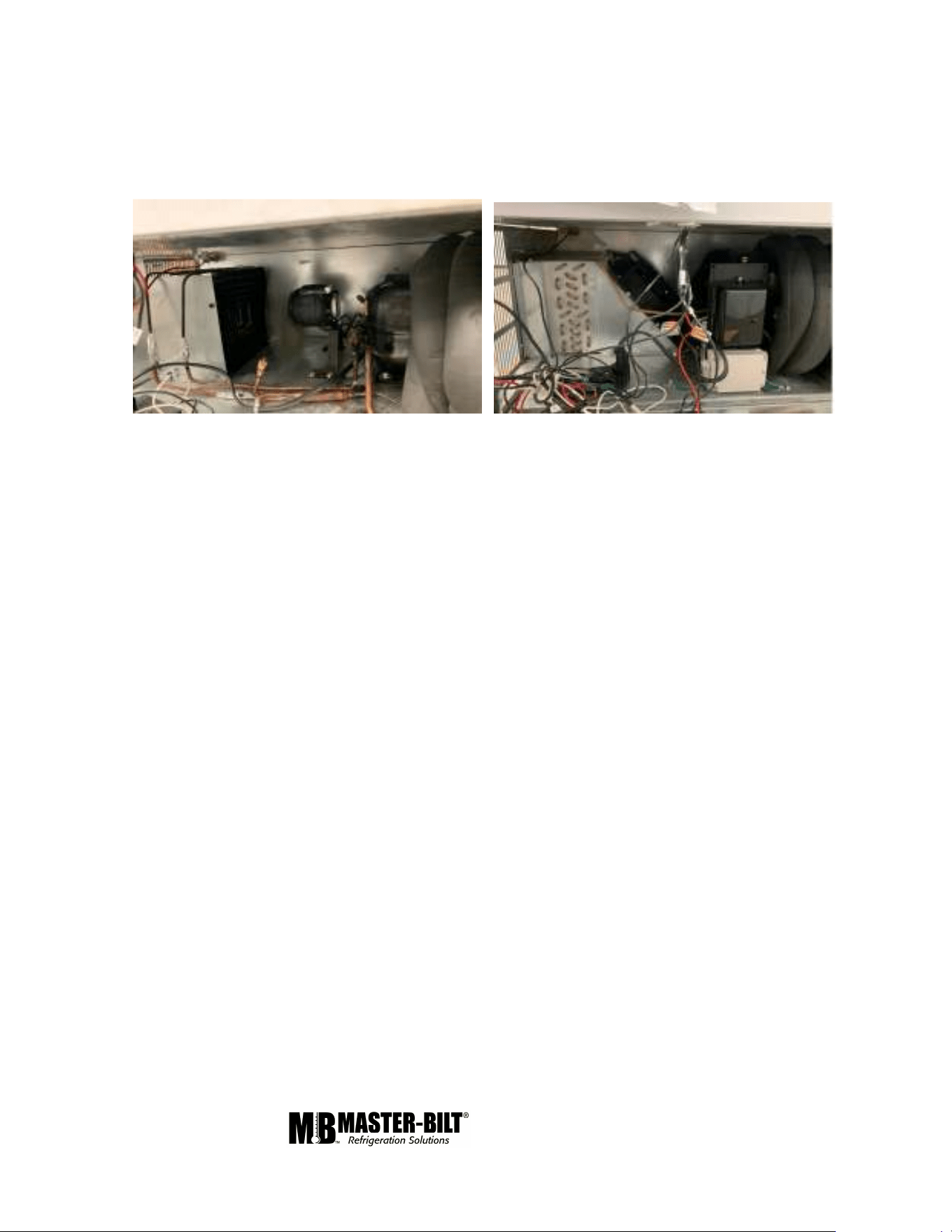
Remove grille and check refrigeration lines to see that they are free (not touching each other or
compressor). Spin condenser fan blade to see that it is free.
Check that all service valves are open.The picture below is Master-Bilt’s standard DD-Unit. The compressor is
hermetic, it is internally spring mounted and ready to run.
Hermetic Compressors, Jelly Roll
Remove cabinet from crate base and slide into location. Cabinet must be level from side to side and front to back.
To comply with Sanitation requirements the cabinet must be mounted on legs (6” high min.) or casters or the base
must be sealed to the floor with an N.S.F. listed silicone sealant.
STARTUP
Uncoil the lead cord and pass it through the hole provided in the grill. While the cabinet is in operation, check the
voltage draw and the amperage draw versus this rating on the nameplate. Voltage should be checked at the
compressor terminals while the compressor is initially starting. The unit is designed to operate at +/- 10% of 115
volts, 60 cycle, single phase. This means that the voltage should be between 103 and 126.5 volts.
After the cabinet has pulled down in temperature to approximately 0F at load line, check the thermostatic control
by turning it to its warmest position. This should shut the compressor off. A separate 20 amp. fuse circuit for each
cabinet is recommended to avoid the possibility of other appliances on a circuit from overloading and causing a
malfunction. Make sure that the electrical service is grounded upon installation.
1/6 Rev. 0 57-02680 9
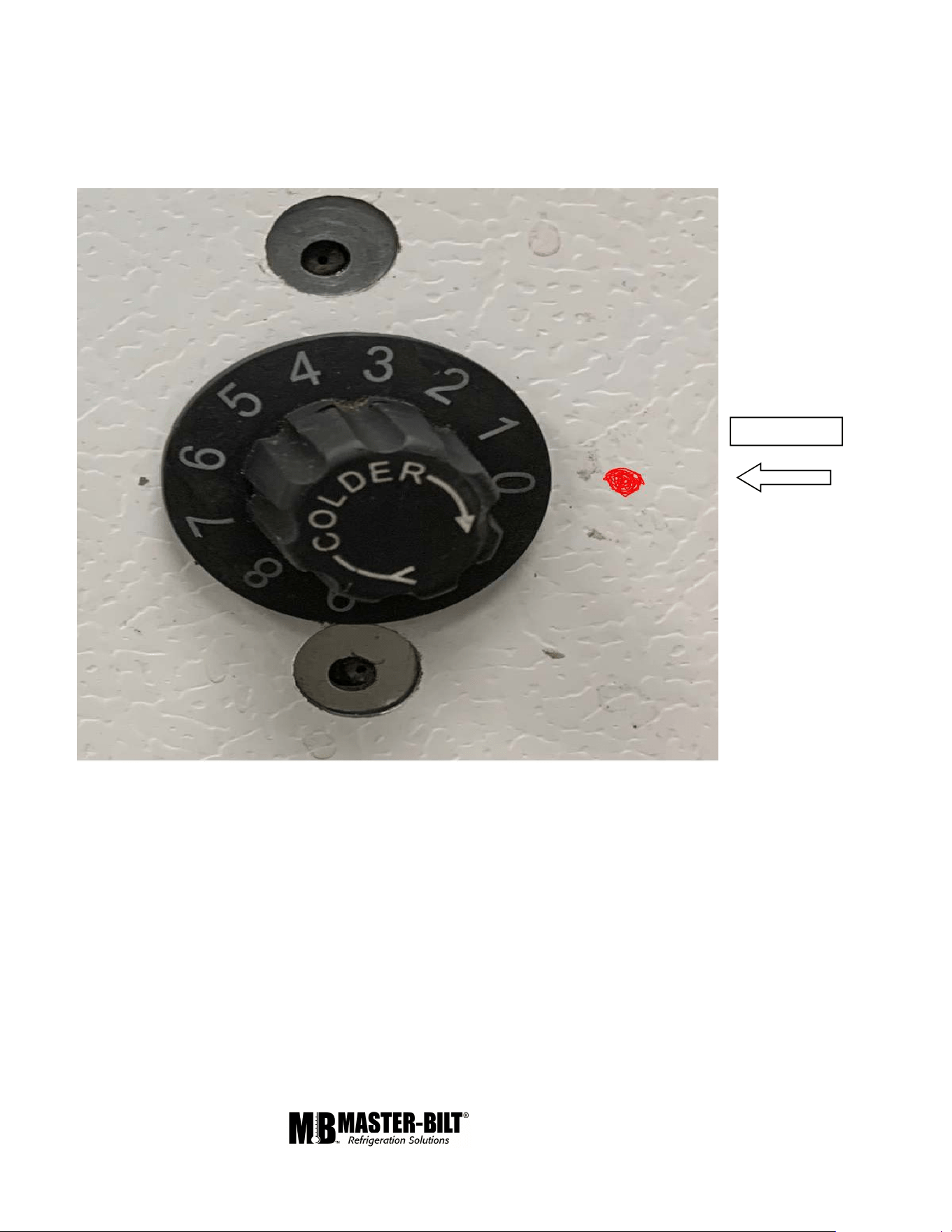
TEMPERATURE CONTROL
The DD cabinet has a temperature control that is adjustable from #1 (warmest setting) to # 9 (coldest setting). Turn
the control knob in line with the punch mark to the desired setting. The temperature control is located near the
condensing unit at the bottom of the cabinet.
WARMEST SETTING
Punch Mark
1/6 Rev. 0 57-02680 10
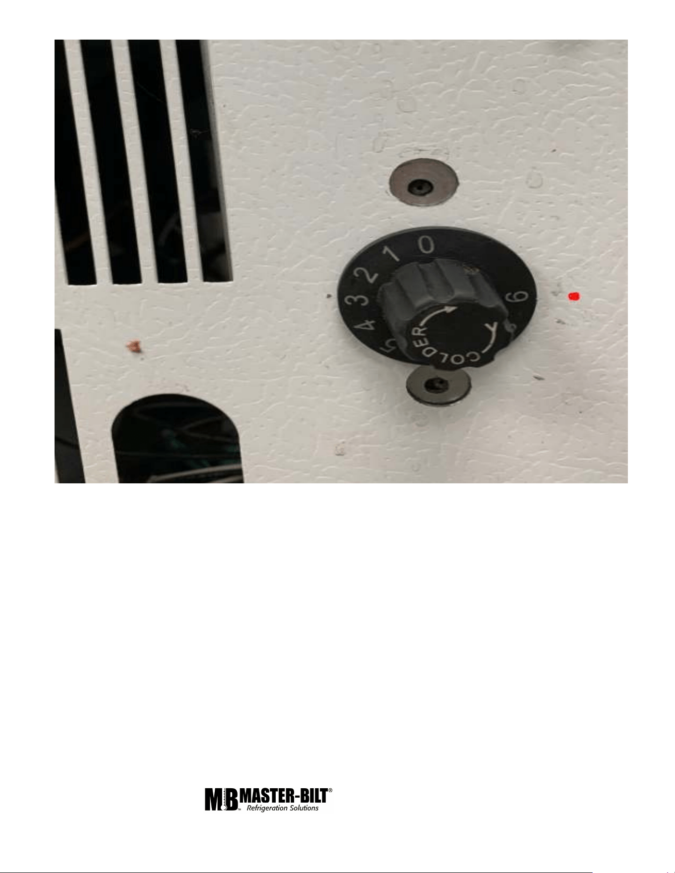
COLDEST SETTING
1/6 Rev. 0 57-02680 11
CLEANING
WARNING: DO NOT REMOVE FROST WITH A KNIFE, PICK, OR SHARP OBJECTS. DO NOT USE
ABRASIVE CLEANERS OR CAUSTIC CLEANERS OR SCOURING PADS
Every 30 to 60 days (depending on frost accumulation), the cabinet should be emptied, warmed up, and wiped
down using a solution of 1 teaspoon of baking soda with 1 quart of water. This solution will help eliminate odors.
Do not use strong soaps or detergents as they leave odors that can contaminate your product. The DD line
cabinets are equipped with a floor drain that exits out the lower rear of the cabinet. This exit has a convenient
garden hose fitting.
If it is not convenient to turn the power off the cabinet, lay a piece of plastic sheeting on the floor of the cabinet and
scrape the frost off walls using a plastic scraper. Do not use metal scrapers. This will damage the interior paint of
the cabinet.
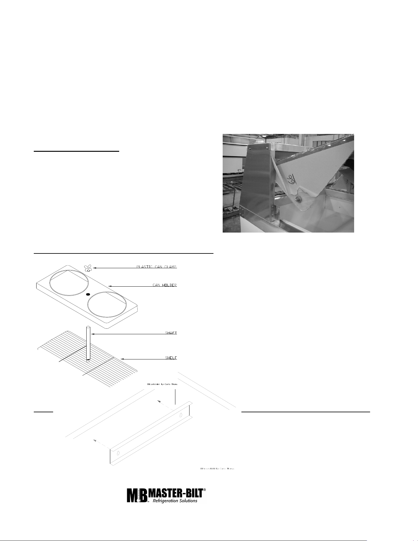
Lid Removal and Cleaning
The lid can be remove by lifting up and out (see picture). The
lid is a high-impact plastic. Wash with warm soapy
water or non-abrasive detergent to avoid scratching.
Can Holder Assembly Removal and Cleaning (Optional)
Remove plastic can clamp by screwing knob off the threaded
shaft. Wash the can holder and can clamp with a non-abrasive
detergent to maintain sanitary gloss. Remove the shaft by
loosening the wing nut and unscrewing the shaft from the shelf.
Wash the shaft and shelf using a non-metallic brush.
Frost- Shield Removal and Cleaning (optional)
When the frost-shields accumulate approximately ½
to 1 inch of frost (about two to three days), remove
it by lifting up to disengage from the keyhole slot.
Remove the frost by holding under running
water until clean. Dry and replace the frost-shield by
engaging screws at the big end of the keyhole
and push down.

1/6 Rev. 0 57-02680 12
OPERATION CONDITIONS AND PRESSURES
With room ambient temperature of +80
o
F and cold cabinet (unit cycling on control):
DD-66 & DD-88 with R-290a
Suction pressure – 2 to 4 psig.
Head pressure – 130 to 160 psig.
If room ambient is low, 60
o
F or lower, then the suction pressure could be as low as 1 psig. Temporary block the
condenser coil to raise head pressure to 1300 psig in order to verify proper charge and a suction pressure of 2 psig
to 4 psig. Remove blockage after pressure check.
DD-26 & DD-46 with R-290a
Suctions pressure 1 to 5 psig
Head pressure 130 to 160 psig
If room abient is below 70
o
F temporarily block the condenser coil to raise the head pressure to 130 psig and
recheck suction pressure. Add R-290a if suction pressure is lower than 1 psig.
SERVICE INSTRUCTIONS (Trouble Shooting Guide)
1. High head pressure and high back
pressure:
A. Condenser coil clogged or
restricted.
B. Condenser fan motor defective.
C. Air in the system.
D. Refrigeration overcharge.
2. Low back pressure and low head pressure:
A. Capillary tube restriction.
B. Refrigerant undercharged.
C. Leak in system.
D. Moisture in system.
3. Pressures normal – cabinet warm:
A. Refrigerant undercharged.
B. Thermostat set too warm.
4. Compressor starts and runs – but cycles
on overload:
A. Low voltage.
B. Overload protector defective.
C. High head pressure (see#1).
5. Compressor will not start – hums, but
cycles on overload:
A. Low voltage.
B. Relay defective.
C. Overload defective.
D. High head pressure (see #1).
6. Cabinet sweating:
A. High ambient humidity.
7. Special service situations
1/6 Rev. 0 57-02680 13
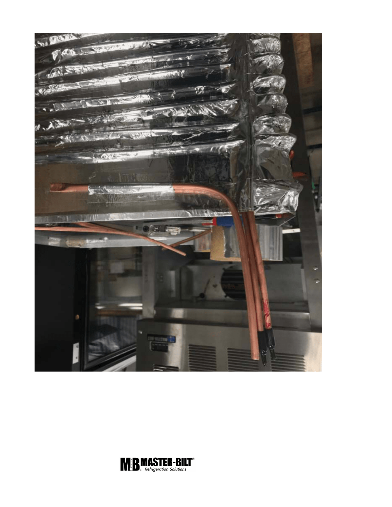
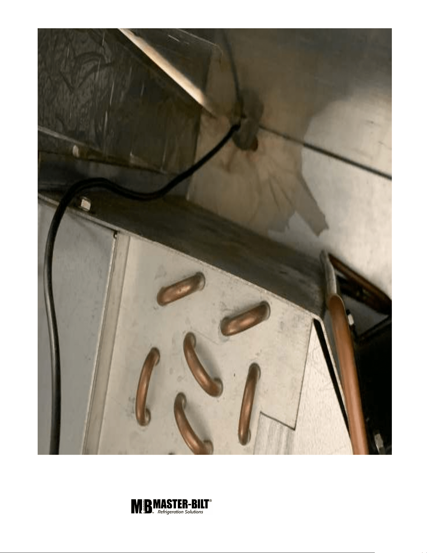
Controller Sensor Probe Location
In DD-46,66 & 88 the bulbwell is a straight 3/8” copper tube placed 3” below the dog house as shown below. For
DD-26 The bulb well sis inverted “L” shape as as shown in the picture. Please make sure the bulb well opening is
properly insulated with permagum. While replacing the sensor probe please make sure the probe is inserted to the
end of the bulb well till it stops. Special care needs to be take during iserting the probe inside the bulb well so that
it is will not be damaged.
1/6 Rev. 0 57-02680 14
1/6 Rev. 0 57-02680 15
1/6 Rev. 0 57-02680 16
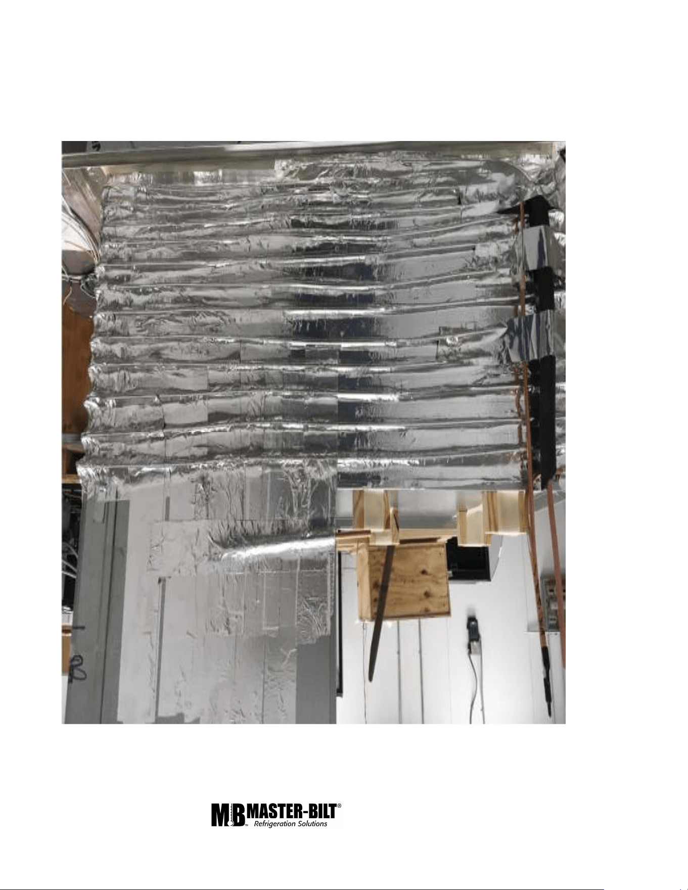
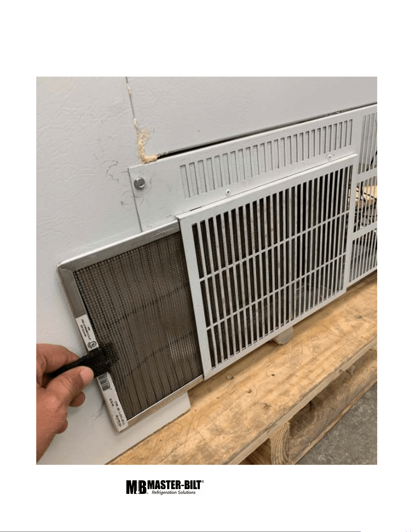
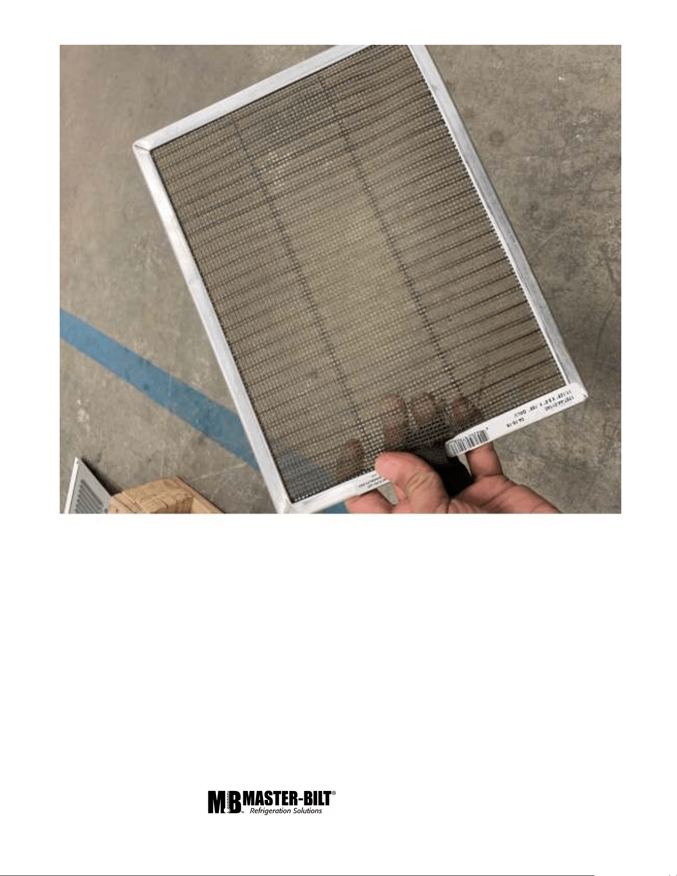
Air Filter for DD-66 & 88 fin & tube condenser
The condenser for DD-66 & 88 is a 5mm fin and tube condenser. A special removable and reuasable air filter has
been provided to protect the condenser and avoid it to be blocked by dust. The filter needs to be removed and
cleaned periodically for optimum performance of the unit. Find below the pictorial presentation of filter removal and
reinstallation after cleaning.
1/6 Rev. 0 57-02680 17
1/6 Rev. 0 57-02680 18
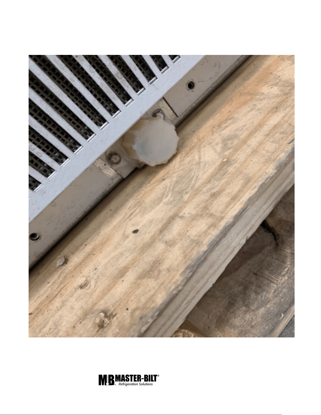
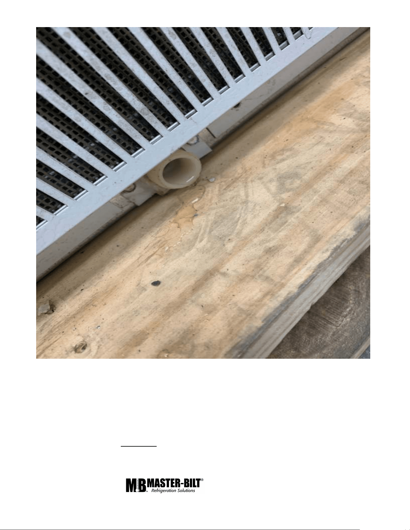
Draining system
The drain outlet is as shown below in the picture.
1/6 Rev. 0 57-02680 19
If moisture or liquid is observed around or under a Master-Bilt
®
cabinet, an immediate investigation should be
made by qualified personnel to determine the source of moisture or liquid. The investigation made should
determine if the cabinet is malfunctioning or if there is a simple housekeeping problem.
Moisture or liquid around or under a cabinet is a potential slip/fall hazard for persons walking by or working
in the general area of the cabinet.
Any cabinet malfunction or housekeeping problem that creates a slip/fall hazard around or under a cabinet
should be corrected immediately
1/6 Rev. 0 57-02680 20
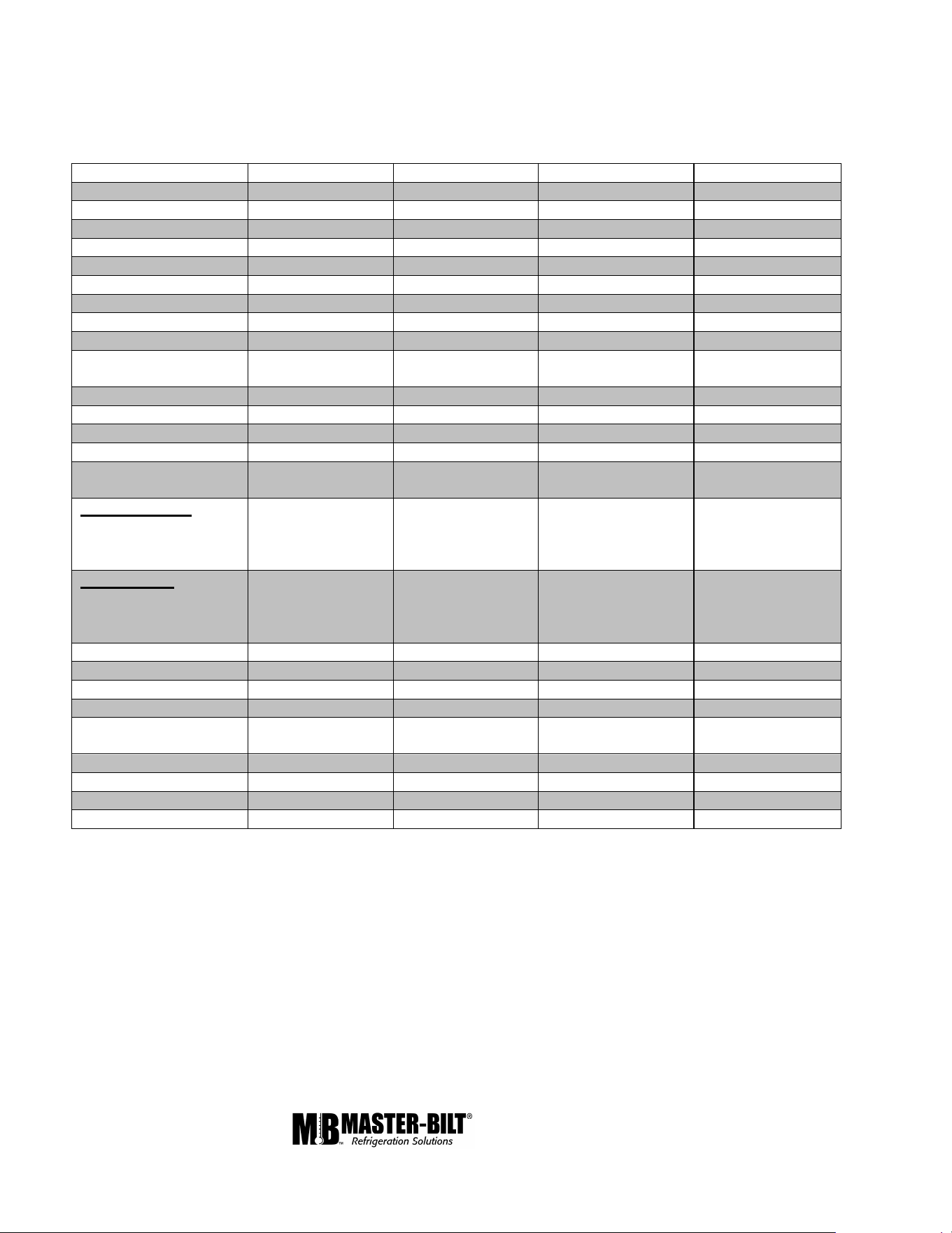
MASTER-BILT PART NUMBERS
The table below gives Master-Bilt
®
part numbers. Use this chart when ordering replacement parts for your
DD Standard, Low Glass and Curved Glass Models.
Description
DD
-
26(
L
)(L
CG
)
DD
-
46
(L
)(L
CG
)
DD
-
66(
L
)(L
CG
)
DD
-
88(
L
)(L
CG
)
LED Driver 23-01878 23-01878 23-01878 23-01878
LED 23-01947 23-01945 23-01947(2 REQ) 23-01950(2 REQ)
Jumper 23-01951 23-01951
Bracket/Attachment 23-01948 23-01948 23-01948 23-01948
Capillary Tube 11-01306 11-01306 11-01306 (2 REQ) 11-01306 (2 REQ)
Compressor 03-50992 03-50992 03-50996 03-50996
Condenser Coil 07-14190 07-14190 07-14186 07-14186
Condenser Fan Blade 15-13093 15-13093
Condenser Fan Motor 13-00311 13-00311 13-13453 13-13453
Condenser Fan Motor
Bracket
13-00754 13-00754
Compressor grommet 03-50994 03-50994 03-50994 03-50994
Drier 09-09864 09-09864 09-09864 09-09864
Controller 19-14239 19-14239 19-14239 19-14239
Controller Sensor 19-14785 19-14785 19-14785 19-14785
Top Gasket
(37-01544)(37-
01536)
(37-01545)(37-
01537)
(37-01546)(37-
01538)
(37-01547)(37-
01539)
FRONT GLASS
(Straight Glass Model)
(Low Glass Model)
(Low Curved Glass)
31-03991
31-03976
31-04011
31-03992
31-03977
31-04012
31-03993
31-03978
31-04013
31-03994
31-03979
31-04014
SIDE GLASS
(Straight Glass Model)
(Low Glass Model)
(Low Curved Glass)
31-03995
31-03480
31-04015
31-03995
31-03480
31-04015
31-03995
31-03480
31-04015
31-03995
31-03480
31-04015
Lid Assembly 394-145A 395-145A 396-145A 397-145A
Light Switch 19-14810 19-14810 19-14810 19-14810
Shelf, Wire 33-01879 33-01879 33-01879 33-01879
Recess Bumper 29-01691 29-01691 29-01691 29-01691
Wire Harness (126”
Power Cord)
21-01741 21-01741 21-01741 21-01741
Condenser Air Filter 44-01140 44-01140
Distributor 11-02006 11-02006
1/6 Rev. 0 57-02680 21
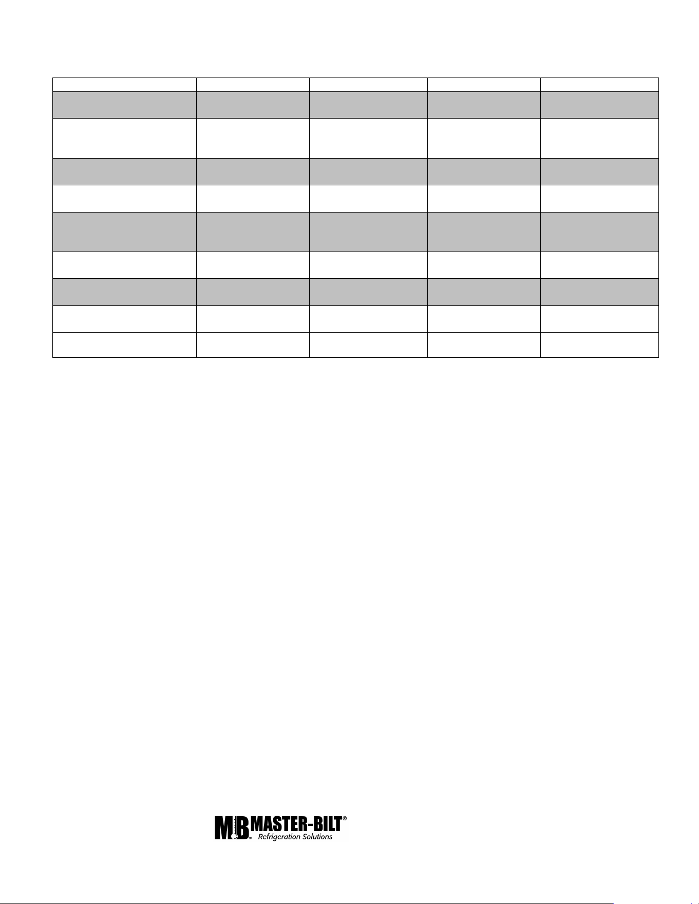
Accessories
Description
DD
-
26(
L
)(L
CG
)
DD
-
46(
L
)(L
CG
)
DD
-
66(
L
)(L
CG
)
DD
-
88(
L
)(L
CG
)
Can Holders –Includes
White Can Covers
A394-20301 A395-20301 A396-20301 A397-20301
Can Covers
Clear
White
44-00984
44-01084
44-00984
44-01084
44-00984
44-01084
44-00984
44-01084
Casters
Set (4), 3” Dia.
A059-11340
A059-11340
A060-11340
A060-11340
Condiment Holders and
Food Pan Display
A059-10650 A062-10650 A060-10650 A061-10650
Individual Containers for
Condiment Holders
(Clear)
44-01020 44-01020 44-01020 44-01020
Dipper Well
w/Installation Kit
A060-20400 A060-20400 A060-20400 A060-20400
Frost Shield (Patented)
Master
-
Bilt Exclusive
A390-11150/A394-
11150
A391-11150/A395-
11150
A392-11150/A396-
11150
A393-11150/A397-
11150
Legs
6” leg kit
A062-11270 A062-11270 A061-11270 A061-11270
DDN Flavor Tags A062-20225 A062-20225 A062-20225 A062-20225
SALE AND DISPOSAL
OWNER RESPONSIBILITY
If you sell or give away your Master-Bilt
®
cabinet you must make sure that all safety labels and the Installation -
Service Manual are included with it. If you need replacement labels or manuals, Master-Bilt will provide them free.
Contact the customer service department at Master-Bilt at (800) 684-8988.
The customer service department at Master-Bilt should be contacted at the time of sale or disposal of your cabinet
so records may be kept of its new location.
If you sell or give away your Master-Bilt
®
cabinet and you evacuate the refrigerant charge before shipment,
Master-Bilt recommends that the refrigerant charge be properly recovered in compliance with section 608 of the
Clean Air Act effective November 1995 and in accordance with all applicable local, regional, or national standards.
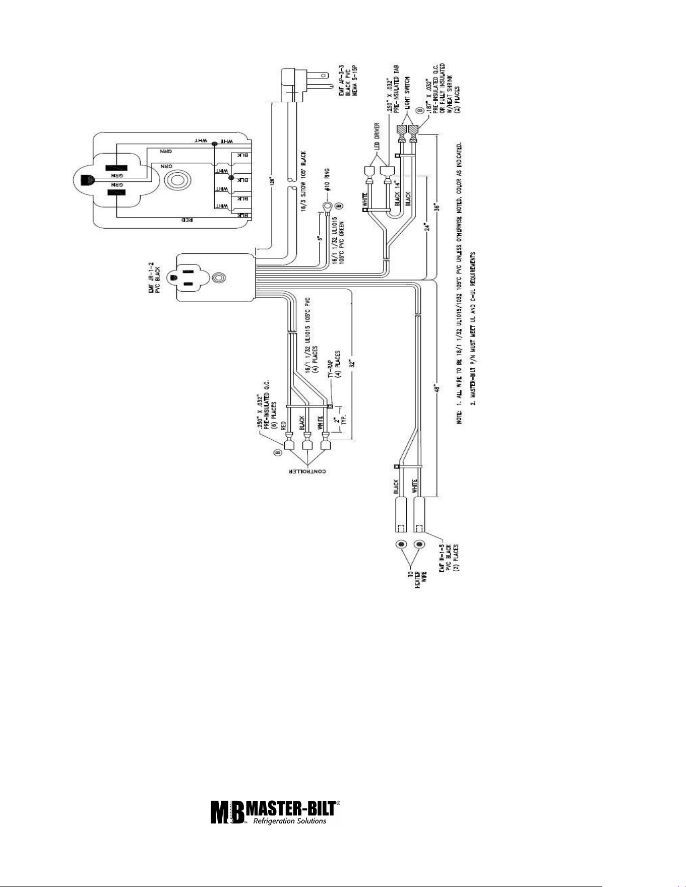
1/6 Rev. 0 57-02680 22
WIRING HARNESS WITH MOLDED JUNCTION ASSEMBLY
LED CONNECTION
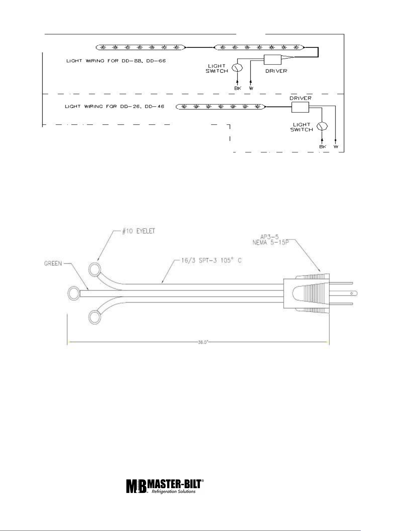
1/6 Rev. 0 57-02680 23
POWER CORD TO CONNECT CONDENSING UNIT TO
MOLDED JUNCTION ASSEMBLY
FOR COMPRESSOR WIRING CONNECTION, PLEASE REFER THE
COMPRESSOR MANUFACTURER WIRING DIAGRAM