THANK YOU
USE AND CARE GUIDE
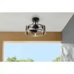
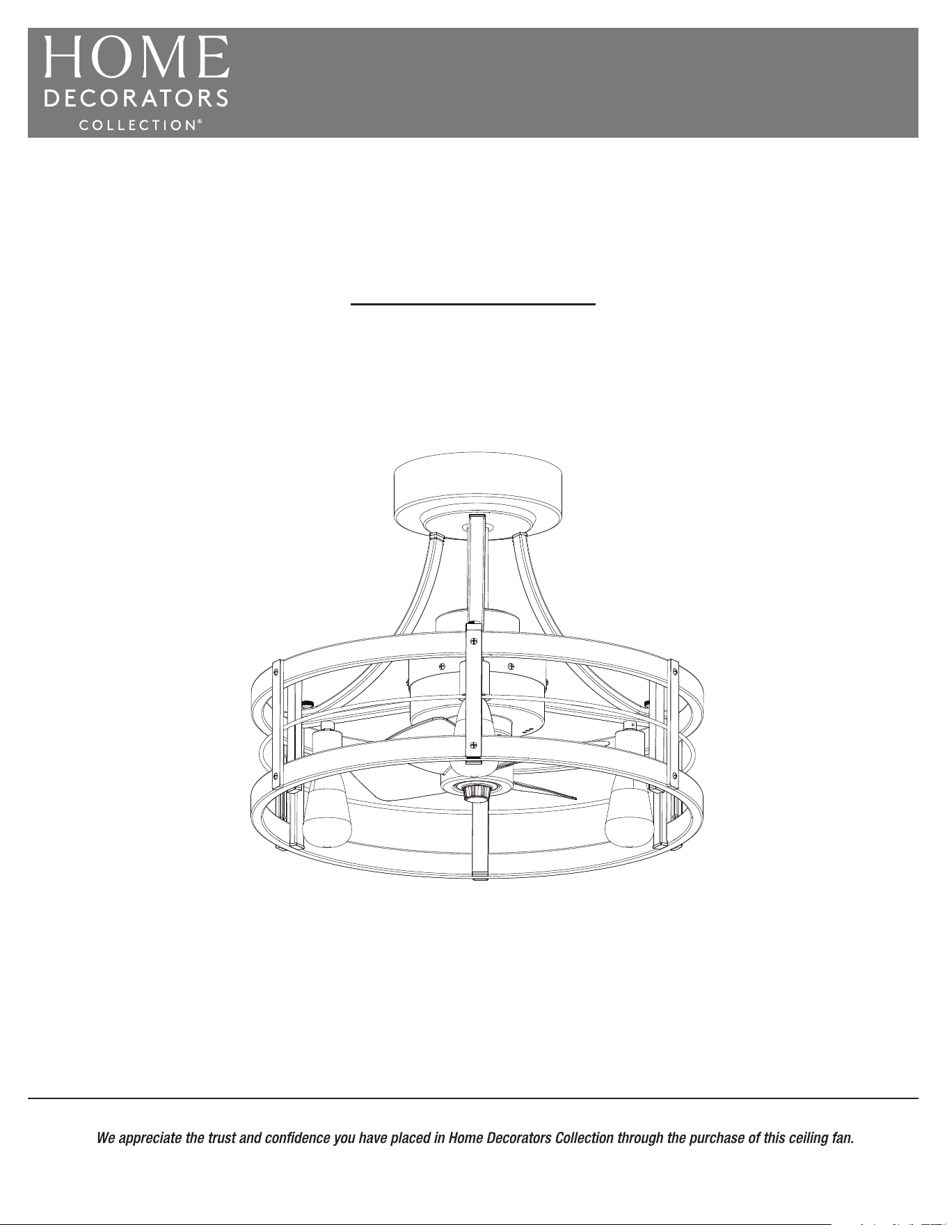
22.5 IN. DIMMABLE LED BULB INDOOR/COVERED OUTDOOR
CEILING FAN WITH REMOTE CONTROL
Questions, problems, missing parts? Before returning to the store,
call Home Decorators Collection Customer Service
8 a.m. - 7 p.m., EST, Monday - Friday, 9 a.m.- 6 p.m., EST, Saturday
1-800-986-3460
HOMEDEPOT.COM/HOMEDECORATORS
Item # 1008674492
Model #SFL-550R
We strive to continually create quality products designed to enhance your home. Visit us online to see our full line of products available
for your home improvement needs. Thank you for choosing Home Decorators Collection!
2
Table of Contents
Table of Contents ............................. . . . . . . .2
Safety Information ............................ . . . . . . . 2
What is covered ........................... . . . . . . . . 3
2-Year Limited Warranty
..................... . . . . . . .
3
What is not covered ........................ . . . . . . . . 3
Warranty .................................... . . . . . . .3
Pre-Installation ............................. . . . . . . . . 4
Planning Installation ....................... . . . . . . . . 4
Tools required
............................ . . . . . . . . 4
Hardware Included
........................ . . . . . . . . 5
Package Contents
. ........................ . . . . . . . .
6
Maintenance .............................. . . . . . . . . 16
Care and Cleaning ........................... . . . . . . . . 16
Troubleshooting ........................... . . . . . . . . 17
Installation ................................ . . . . . . . . 7
Operation ................................. . . . . . . . .15
Safety Information
READ AND SAVE THESE INSTRUCTIONS
INTENDED USE
RISK TO CHILDREN AND IMPAIRED PERSONS
SAFETY OF OPERATION ENVIRONMENT AND
INSTALLATION
Please read and understand this entire manual before attempting
to assemble, install or operate the product. Thoroughly review all
assembly information and drawings and be sure you understand
the assembly requirements. Do not use the fan unless you have
read these instructions.
Use this appliance only as described in the manual. Any other use
shock or injury to persons. The manufacturer assumes no
responsibility for damage or injury due to unauthorized use or
the product warranty.
This fan is designed for indoor and covered outdoor use. This
product is intended for commercial use.
This fan is not intended for use by people (including children) with
reduced physical, sensory or mental capabilities or lack of
experience and knowledge unless they have been given
supervision or instruction concerning use of the fan by a person
responsible for their safety.
Close supervision is necessary when any appliance is used by or
near children.
Keep the fan out of reach of young children.
Do not use this fan in uncovered outdoor areas or expose it to
weather or elements.
Ensure power is off before beginning installation. Before
installing, servicing or cleaning, switch power off at service panel
and lock the service disconnecting means to prevent power from
being switched on accidentally. When the service disconnecting
means can not be locked, securely fasten a prominent warning
device, such as a tag, to the service panel.
persons in accordance with all applicable codes and standards,
Installation and wiring must be in accordance with the National
Electrical Code, ANSI/NFPA 70, and all local codes. If you are
unfamiliar with or unable to comply with these requirements, have
the ceiling fan installed by a licensed electrician.
When cutting or drilling into wall or ceiling, do not damage
electrical wiring and other hidden utilities.
Mount ceiling fan directly to a structural framing member or to
a metal outlet box marked “Acceptable for Fan Support of 35 lb.
or less”. For outlet box mounting, use mounting screws provided
with the outlet box.
When using an existing outlet box, make sure it is securely
attached to the building structure and can support the full weight
of the fan. Most outlet boxes commonly used for the support of
therefore need to be replaced. Do not use a plastic outlet box.
Failure to follow this instruction can result in serious injury or death.
To reduce the risk of injury to persons, install ceiling fan so that the
blade guard is at least 10 feet above the oor.
All set screws must be checked and retightened where
necessary before installation.
After making the wire connections, the wires should be spread
apart with the grounded conductor and the equipment-grounding
conductor on one side of the outlet box and the ungrounded
conductor on the other side of the outlet box.
The splices after being made should be turned upward and
pushed carefully up into the outlet box.
When installation is complete, make sure all connections are
secure to prevent ceiling fan from falling.
appliances. Do not operate in the presence of explosive and/or
precautions, including the following, should always be
injury to persons.
WARNING: When using electrical appliances, basic safety
WARNING: Risk to Children and Impaired Persons
□
□
□
□
□
□
□
□
□
□
□
□
□
□
□
□
□
□
3 HOMEDEPOT.COM/HOMEDECORATORS
Please contact 1-800-986-3460 for further assistance.
Safety Information (continued)
OPERATION SAFETY
DISPOSAL
Do not use the fan to exhaust hazardous or explosive materials
and vapors.
Make sure that the fan does not get wet (water splashes etc.).
Do not immerse the fan in water or other liquids or use near sinks,
baths, or showers.
Place this fan away from curtains, draperies, tablecloths and
other fabrics, since they may be drawn into the fan, damage the
Keep work area clean and well lit.
To reduce risk of electrical shock and injury to persons, do not
use in a window.
Do not operate the fan until fully assembled with all parts properly
in place.
Do not leave the fan unattended when in use.
Always switch power off at service panel and lock the service
disconnecting means when not in use, before moving fan from
one location to another, before putting on or taking off parts, and
before cleaning or performing maintenance. When the service
disconnecting means can not be locked, securely fasten a
prominent warning device, such as a tag, to the service panel.
All servicing, apart from ordinary cleaning, should be
electricians should not disassemble, repair or rebuild the fan.
There are no user-serviceable parts inside.
Do not subject the fan to violent impacts.
Do not operate any appliance after the appliance malfunctions, or
if it has been dropped or damaged in any manner. Discard fan or
return to an authorized service facility for examination and/or
repair.
Do not insert your hand or other objects into the guard or the
movable parts.
We encourage you to participate in a recycling program, so please
observe local regulations for proper disposal of discarded products.
Recycle raw materials instead of disposing of as waste. The
machine, accessories and packaging should be sorted for
environmentally friendly recycling.
Do not touch the fan with wet hands.
Do not disassemble or modify the fan. Do not bend the fan blade
or the blade guard when cleaning.
with any solid-state speed control device.
Do not use this fan as a dryer. Make sure nothing is blocking the
WARNING:
NOTICE:
To reduce the risk of re, electric shock or injury
Save these instructions. Refer to them frequently and use
to persons, do not use replacement parts that have not been
recommended by the manufacturer (e.g. parts made at home
using a 3D printer).
them to instruct others who may use this fan. If you are to loan someone
this fan, loan them these instructions also.
Warranty
2-YEAR LIMITED WARRANTY
WHAT IS COVERED
The manufacturer warrants this product to be free from manufacturing defects in the material and workmanship under normal use for a
period of two years after the date of purchase by the original purchaser.
WHAT IS NOT COVERED
This warranty does not cover transit damages. This warranty does not apply to damages from accident, misuse, alteration of any kind to the
ortion of
the product. Servicing performed by unauthorized persons shall render the warranty invalid.
This warranty is not responsible for damages of any kind, including accident and consequential damages. Some states do not allow the
exclusion or limitation of the incidental or consequential damages, so the above exclusion or limitation may not apply to you. This warranty
Contact the Customer Service Team at 1-800-986-3460 or visit www.HOMEDEPOT.com/HOMEDECORATORS.
□
□
□
□
□
□
□
□
□
□
□
□
□
□
□
□
□
□
4
Pre-Installation
PLANNING INSTALLATION
Remove all parts from the package, and verify that everything listed in the
Package Contents section are present.
Inspect the product carefully to make sure no breakage or damage occurred during shipping.
Do not discard the packing material until you have carefully inspected and satisfactorily operated the product.
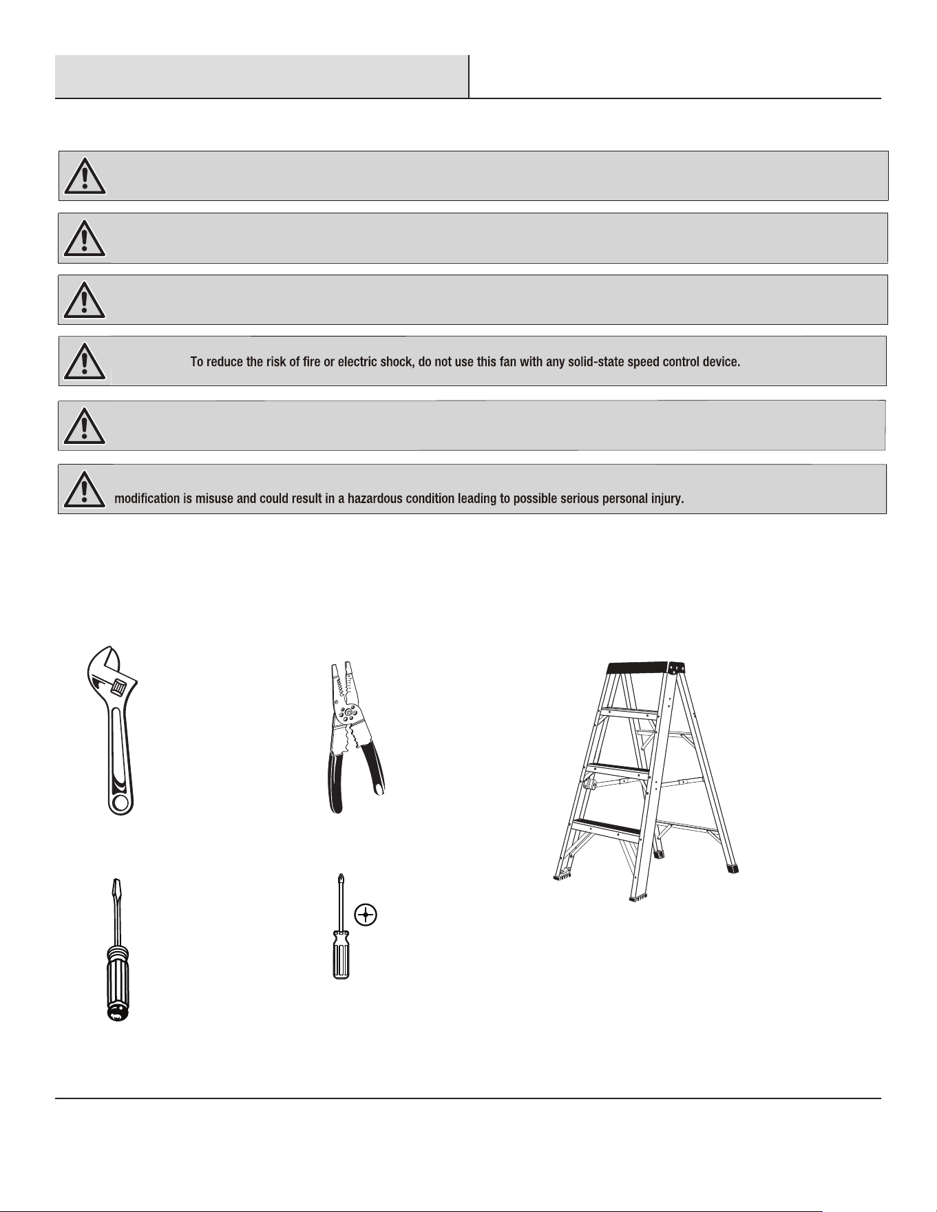
TOOLS REQUIRED
Adjustable wrench Wire cutters/Strippers
Phillips
screwdriver
Flat head
screwdriver
Step ladder
WARNING: Items in this section are not assembled to the product by the manufacturer and require installation. Use of a product that may
have been improperly assembled could result in serious personal injury.
the fan installation, cleaning, or servicing.
To reduce the risk of re, electric shock, or injury to persons, unplug or disconnect the appliance from the power supply before
WARNING:
WARNING: To reduce the risk of personal injury, do not bend the blade brackets when installing the brackets, balancing the blades, or
WARNING:
WARNING: If any parts are damaged or missing, do not operate this product until the parts are replaced. Use of this product with damaged or
missing parts could result in serious personal injury.
WARNING: Do not attempt to modify this product or create accessories not recommended for use with this product. Any such alteration or
LOOP
STRIP
WIREGAGE
PLERS
22
20
18
16
14
12
10
cleaning the fan. Do not insert foreign objects in between rotating fan blades.
□
□
□
5 HOMEDEPOT.COM/HOMEDECORATORS
Please contact 1-800-986-3460 for further assistance.
Pre-Installation (continued)
AA BB
HH
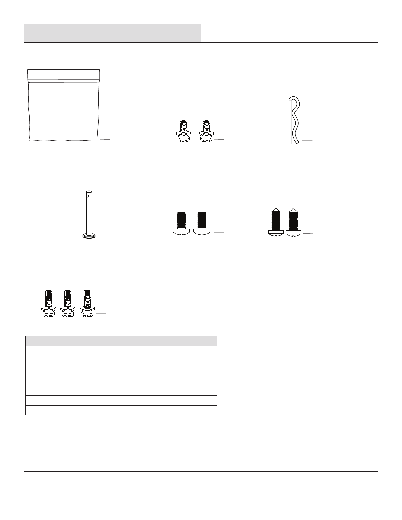
HARDWARE INCLUDED
Part Description Quantity
AA Installation hardware bag 1
BB Canopy mounting screws
2
EE
CC
GG
DD
CC
DD
EE
Pin
Securing bolt
Securing screws
2
1
1
GG Remote control wall mount screws 2
HH
Decorative arms mounting screws 3
6
Pre-Installation (continued)
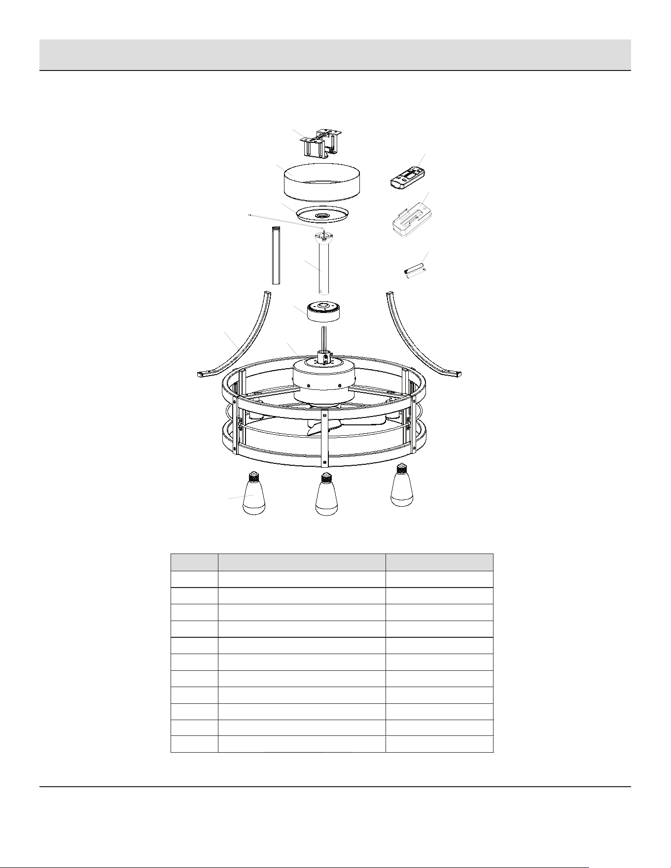
PACKAGE CONTENTS
Part Description Quantity
A Mounting bracket 1
B Canopy 1
C Decorative cap
Decorative arms
1
D Pivot ball/downrod assembly 1
E Motor housing cap 1
F Fan body 1
G LED bulb 3
H
I
J
K
Remote control EHU-659TRF
Remote control wall mount
Remote control AAA batteries
1
1
2
3
F
G
H
I
J
K
A
B
C
D
E
7 HOMEDEPOT.COM/HOMEDECORATORS
Please contact 1-800-986-3460 for further assistance.
Installation
□
□□
If your installation site does not have an existing
UL-listed metal outlet box, one must be installed
before proceeding. Make sure box is mounted directly
to the building structure using ceiling joist screws
provided with the box.
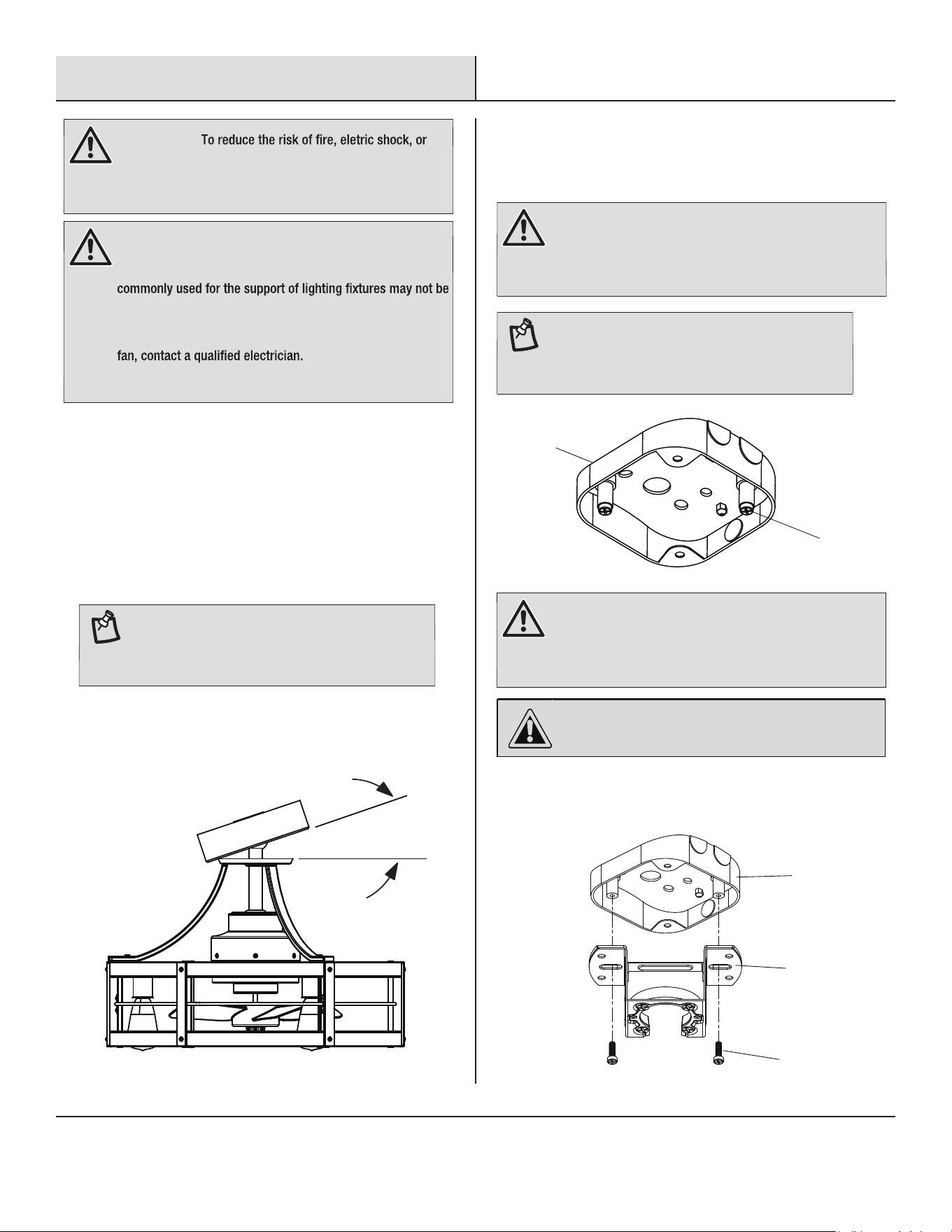
Once installed, there must be at least 10 ft. clearance
between the bottom of the ceiling fan and the floor.
Ceilings taller than 8 ft. may benefit from an extended
length downrod (not included) to achieve the best
results.
the horizontal canopy.
□
Angled ceilings must not be steeper than 18 degrees from
1
Installing the Ceiling Fan Mounting
Bracket
□ Remove the screws (FF) from the outlet box and then attach
the ceiling mounting bracket (A) to the outlet box on the wall
by tightening the screws (FF).
WARNING:
personal injury, turn off power to room and wall switch by
removing fuses or turning off circuit breakers as needed
before beginning installation.
WARNING:
Mount fan only to a metal outlet box marked
acceptable for fan support and use only the mounting screws
provided with the outlet box. Plastic outlet boxes and outlet
acceptable for fan support and may need to be replaced. If
you are unsure whether your outlet box is appropriate or
uncertain about the proper method for mounting your ceiling
WARNING:
Using the screws (FF) which do not come
with the fan but should be provided with the outlet box,
attach the ceiling mounting bracket (A) to the electrical box,
passing the 120V electrical supply wires through the hole
in the center of the mounting bracket (A).
CAUTION:
If you are installing the mounting bracket
(A) for an angled orientation, make sure the open end of the
bracket (A) is installed facing the lower point of the ceiling.
18° max.
NOTE:
Extended-length downrods longer than 48 in.
will also require a downrod wire extension kit (not
included, available from the retailer where you
purchased your fan).
WARNING:
Remove any existing ceiling fan or light where
you intend to install this ceiling fan. Verify the existing
outlet box is marked acceptable for fan support up to 35 lb.
and that it is securely fastened to the ceiling joists.
NOTE:
For Canada installations, refer to the Canada
Installations Addendum located in the Canada
Installation Hardware Bag and install the eye bolt or
anchor assembly now.
OUTLET
BOX
FF
OUTLET BOX
FF
A
8
Installation (continued)
2
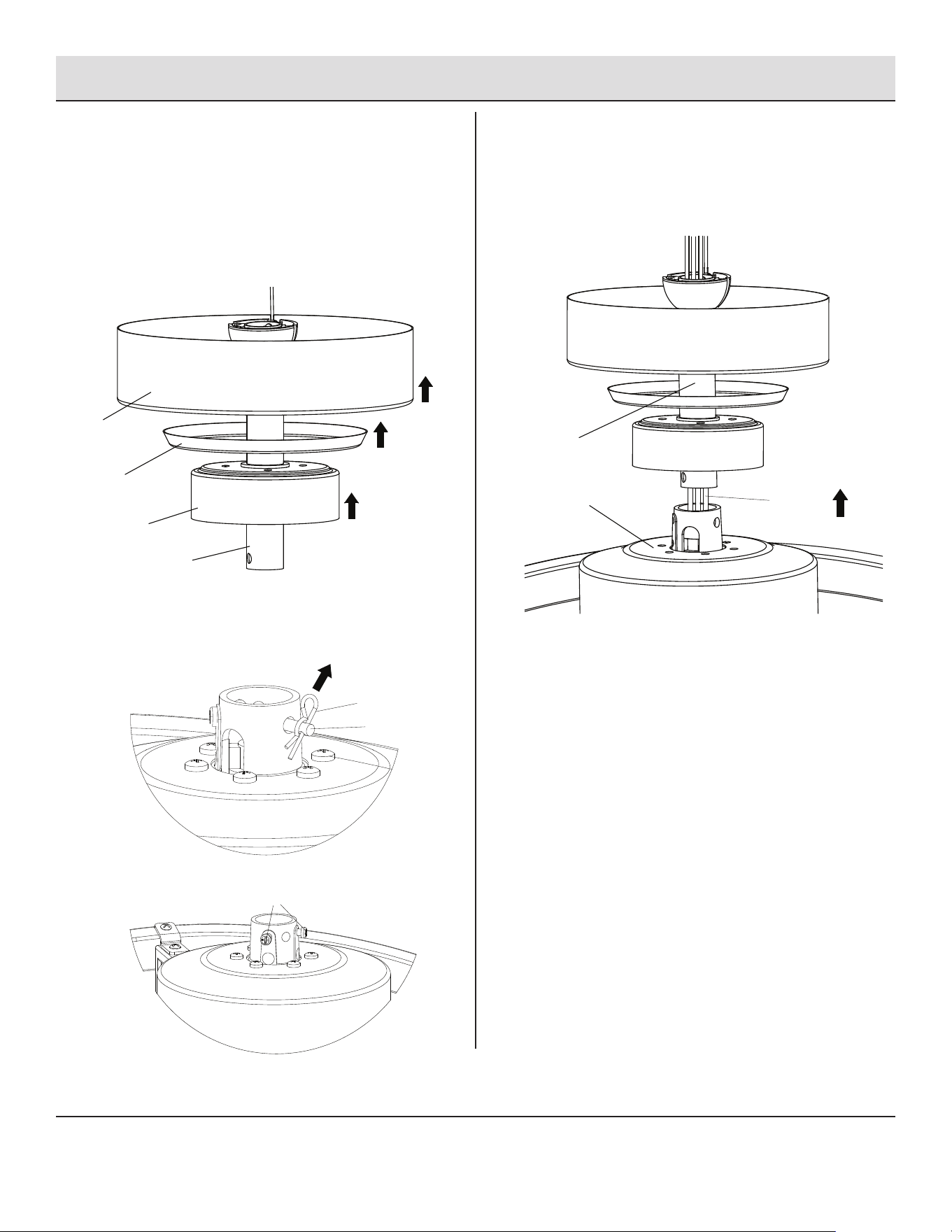
Preparing For Mounting
3
Routing the Wires
□ Follow the order and with the cupped side facing up, place
the canopy (B) and the decorative cap (C) through the
pivot ball/downrod assembly (D).
□ With the cupped side facing down, place the motor housing
cap (E) through the pivot ball/downrod assembly (D).
□ Remove the pin (CC) and then pull out the securing bolt (DD).
□ Loosen the securing screws (EE).
B
CC
DD
EE
C
E
D
□ Carefully feed the four electrical wires of the fan body (F)
through the pivot ball/downrod assembly (D) .
D
electrical
wires
F
9 HOMEDEPOT.COM/HOMEDECORATORS
Please contact 1-800-986-3460 for further assistance.
Installation (continued)
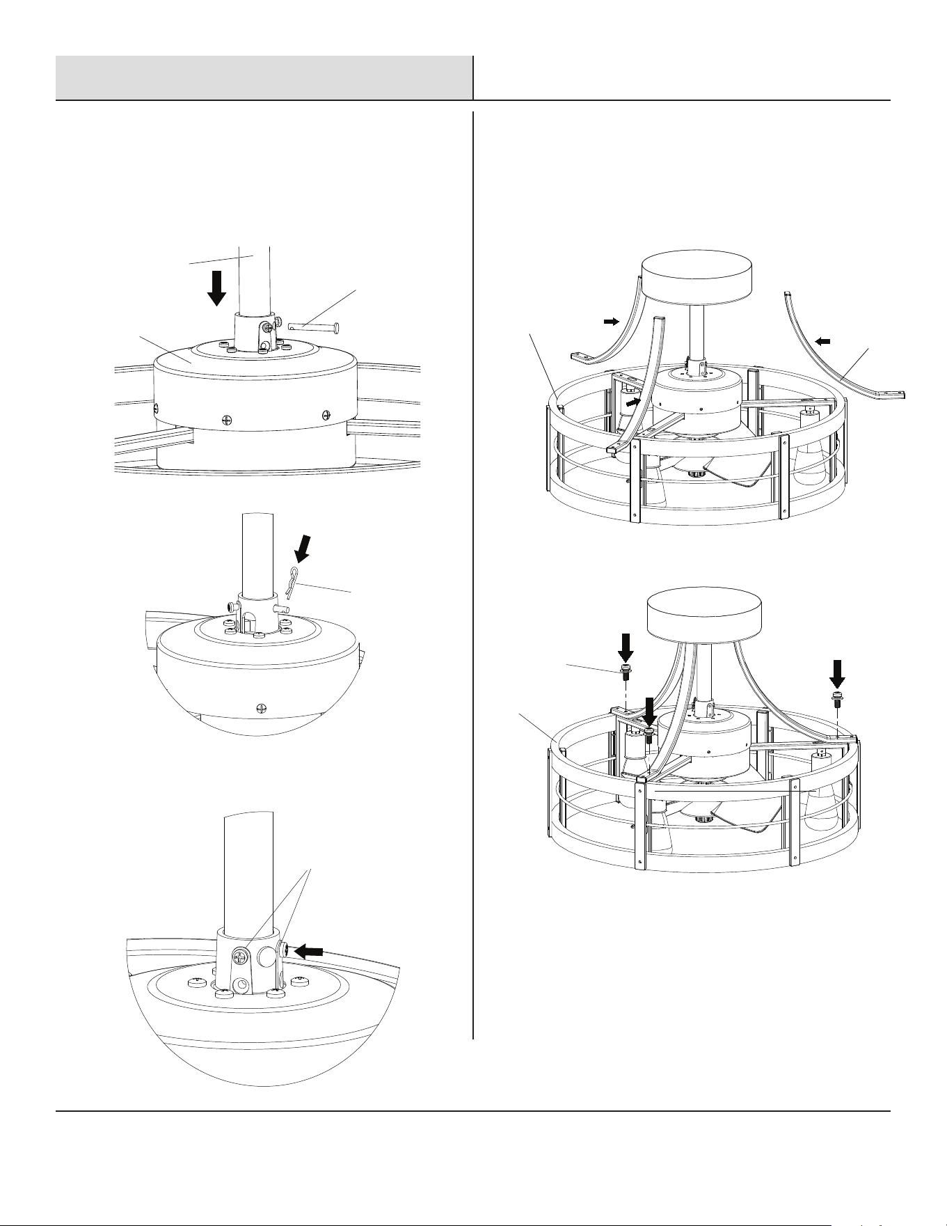
□ Attach the three decorative arms (K) to the fan body (F) and
secure them by tightening the screws (HH).
F
K
HH
F
4
Assembling the Fan Body
5
Attaching the Decorative Arms
□ Insert the downrod assembly (D) into top of fan body (F),
aligning the holes. Insert the securing bolt (DD) into the
aligned holes and then secure the bolt (DD) with the pin (CC).
CC
DD
D
F
□ Tighten the securing screws (EE).
EE
10
Installation (continued)
6
Attaching the Fan to the Electrical
Box
7
Wiring the Fan
WARNING:
Once you begin the process of hanging the
ceiling fan, do not leave the fan unattended until the
installation process is complete.
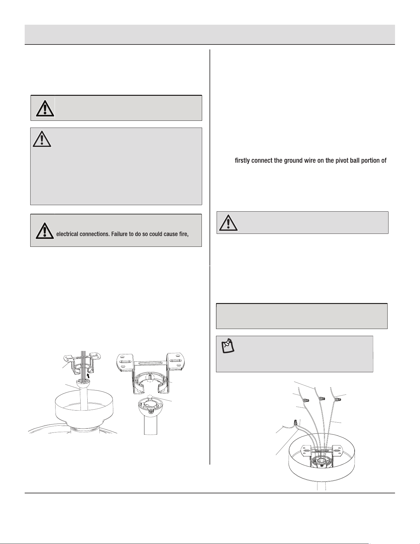
□ Carefully lift the assembled fan up to the mounting
bracket (A) while slightly above the bottom of the mounting
bracket for better positioning.
□ Seat the pivot ball portion of the downrod assembly (D) in the
mounting bracket socket (A). Rotate the fan as needed so the
tab on the mounting bracket socket (A) seats in the groove in
the pivot ball/downrod assembly (D).
□ Feed all the electrical wires through the long hole on top of
the mounting bracket (A).
WARNING:
The pivot ball/downrod assembly (D) cannot
be inserted upward through from the bottom of the
mounting bracket (A). Position the pivot ball portion of the
pivot ball/downrod assembly (D) above the bottom of the
mounting bracket (A) so that when pivot ball/downrod
assembly (D) seats in the mounting bracket (A), adjust and
pull downward to secure. Failure to engage the fan’s tab
into the groove on the mounting bracket (A) could allow the
fan to wobble and/or fall. A falling fan could cause serious
personal injury or death.
A
D
tab on the
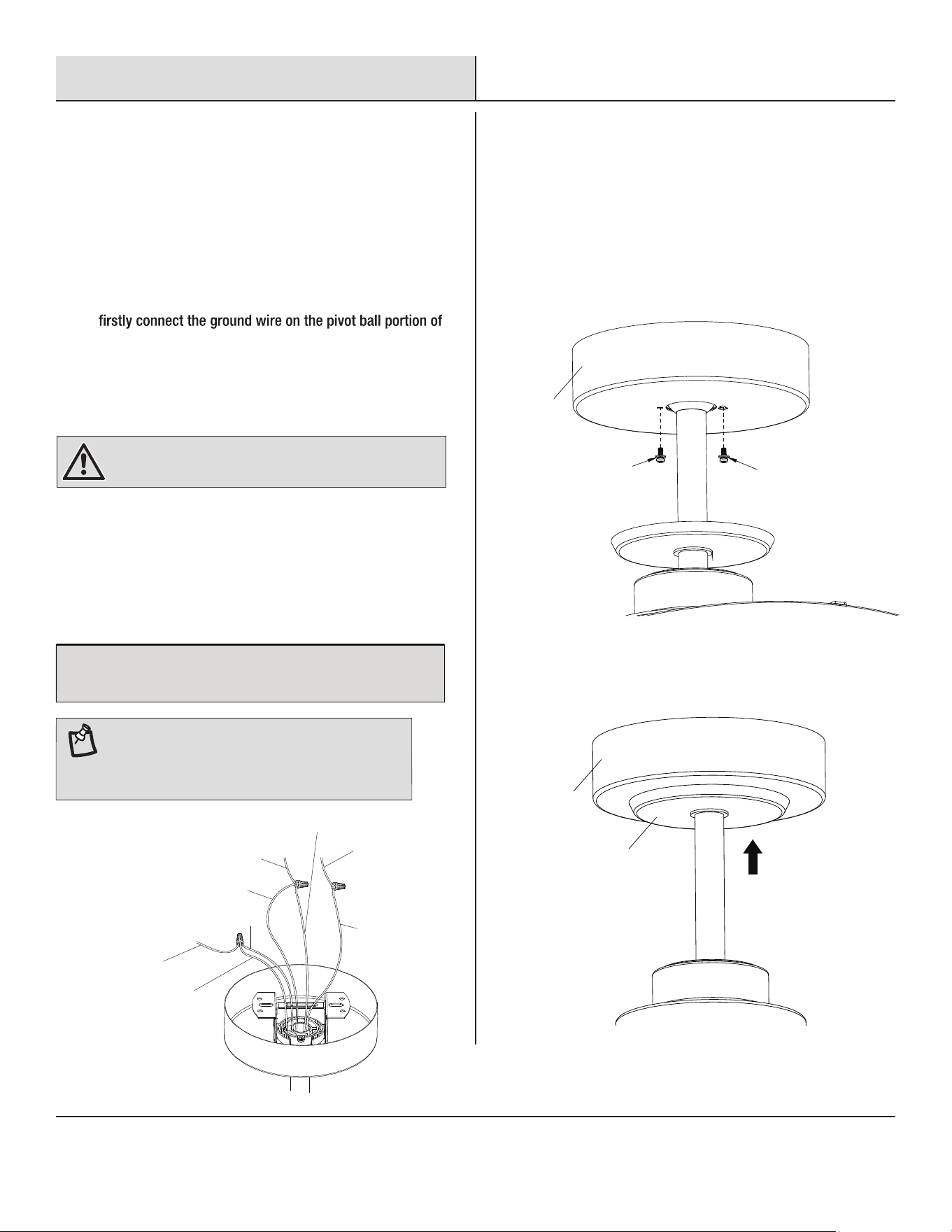
ground wire on the
pivot ball portion of
the pivot ball/downrod
assembly
ground wire of
the outlet box
motor ground wire
black motor hot wire
blue lighting hot wire
hot wire 1 of the outlet box
white wire of the
outlet box
white wire
hot wire 2 of the outlet box
mounting
bracket
groove
on the
downrod
WARNING:
Verify the power has been disconnected to
both the room and the wall switch before making the
electric shock, serious personal injury, or death.
□
If your outlet box has two hot wires, choose the supply wire
that matches the wall switch you want to use for the ceiling
fan and connect it to the black motor hot wire of the fan.
Then connect the other hot wire to the blue lighting
hot wire of the fan.
□ Connect the white (neutral) supply wire to the fan white wire.
□ Connect the hot wires to the fan hot wires in either of the
following two ways.
□
□
If your outlet box has a ground wire (green or bare copper),
the pivot ball/downrod assembly (D) to the motor ground
wire of the fan, and then connect them to the ground wire.
If there is no ground wire in your outlet box, connect the
ground wire on the pivot ball portion of the pivot ball/
downrod assembly (D) to the motor ground wire of the fan.
WARNING: Do not remove the ground wire on the pivot
ball portion of the pivot ball/downrod assembly (D).
□ Install a plastic wire nut over each connection to secure.
Reinforce with electrical tape as needed to make sure no
bare wire is visible at the wire nuts (except for a bare
ground wire, if present).
□ Spread the wires apart so the ground wires and white wires
go to one side and the hot wires go to the other, then carefully
tuck all the wire connections up into the outlet box.
NOTICE:
Orient the wires so the wire nuts are facing up and are
not touching each other. This will help minimize potential noise once
the installation is complete.
NOTE:
For Canada installations, refer to the Canada
Installations Addendum located in the Canada
Installation Hardware Bag and install the eye bolt or
anchor assembly now.
11 HOMEDEPOT.COM/HOMEDECORATORS
Please contact 1-800-986-3460 for further assistance.
Installation (continued)
BB
BB
B
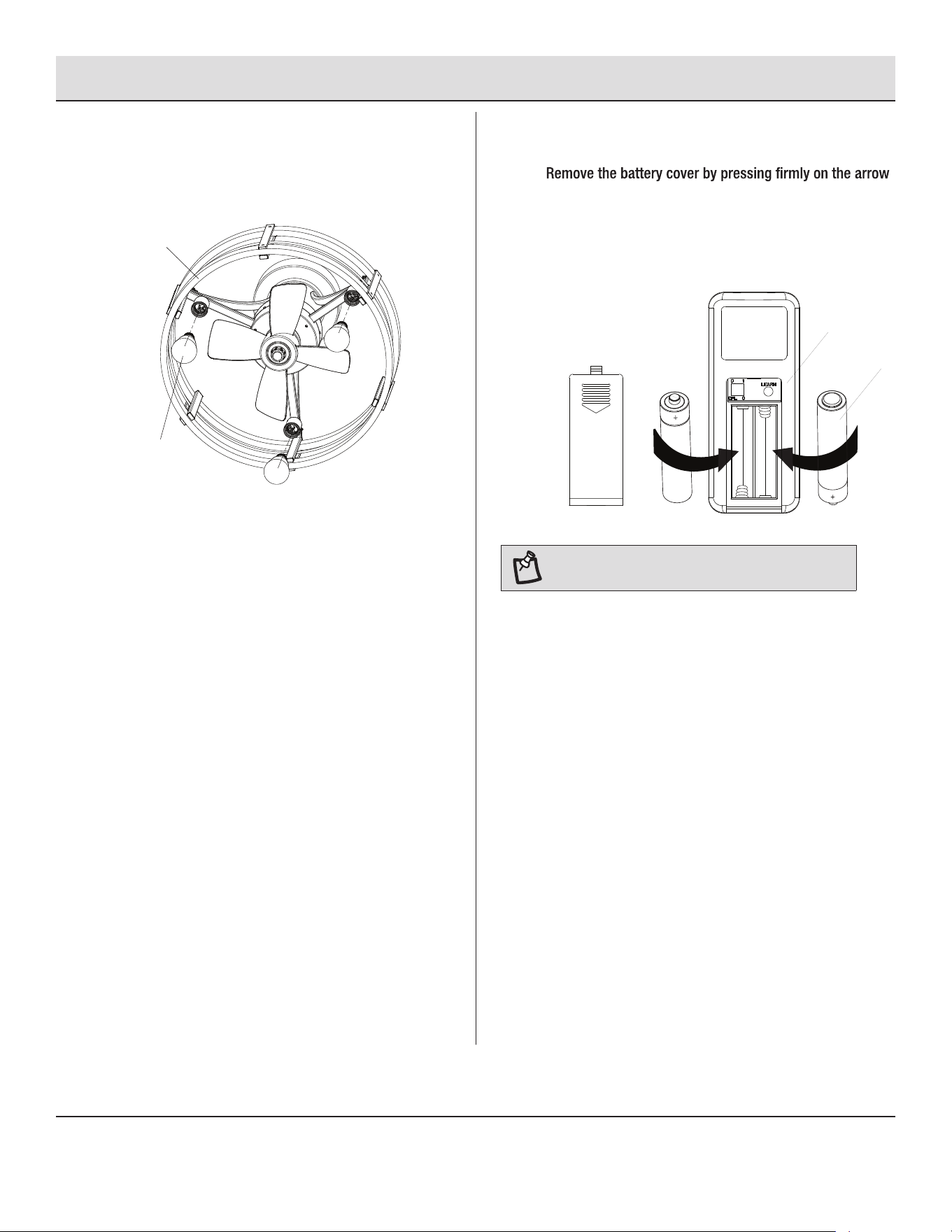
□ Push the decorative cap (C) upward onto the canopy (B).
C
B
□
If your outlet box has the only one hot wire, connect the fan
black motor hot wire and the fan blue lighting hot wire
together and then connect them to the hot supply wire.
□ Push the canopy (B) upward to cover up the outlet box, the
mounting bracket and electrical wires.
□ Rotate the canopy (B), aligning the screw holes with holes on
the mounting bracket. Secure the canopy (B) onto the
mounting bracket by tightening the canopy mounting screws (BB).
9
Placing the Decorative Housing
8
Wiring the Fan (Optional)
□ Connect the white (neutral) supply wire to the fan white wire.
□ Connect the hot wires to the fan hot wires in either of the
following two ways.
□
□
If your outlet box has a ground wire (green or bare copper),
the pivot ball/downrod assembly (D) to the motor ground
wire of the fan, and then connect them to the ground wire.
If there is no ground wire in your outlet box, connect the
ground wire on the pivot ball portion of the pivot ball/
downrod assembly (D) to the motor ground wire of the fan.
WARNING: Do not remove the ground wire on the pivot
ball portion of the pivot ball/downrod assembly (D).
□ Install a plastic wire nut over each connection to secure.
Reinforce with electrical tape as needed to make sure no
bare wire is visible at the wire nuts (except for a bare
ground wire, if present).
□ Spread the wires apart so the ground wires and white wires
go to one side and the hot wires go to the other, then carefully
tuck all the wire connections up into the outlet box.
NOTICE:
Orient the wires so the wire nuts are facing up and are
not touching each other. This will help minimize potential noise once
the installation is complete.
NOTE:
For Canada installations, refer to the Canada
Installations Addendum located in the Canada
Installation Hardware Bag and install the eye bolt or
anchor assembly now.
ground wire on the
pivot ball portion of
the pivot ball/downrod
assembly
ground wire of
the outlet box
motor ground wire
black motor hot wire
hot wire of the outlet box
white wire of the
outlet box
white wire
blue lighting hot wire
12
Installation (continued)
11
Installing the Batteries
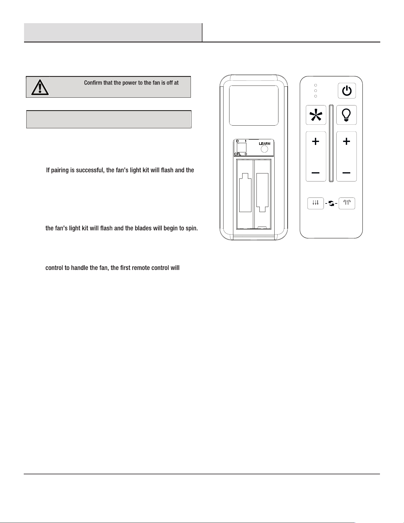
□
and sliding the cover off.
□ Install two remote control batteries (J) provided into the
remote control (H).
□
Replace the battery cover on the remote control (H).
□ Insert the three LED bulbs (G) into the light holders of
the fan body (F) and rotate clockwise to secure.
10
Installing the LED Bulbs
G
F
+
+
J
H
NOTE: If the batteries that come with the fan run out,
they can be replaced with 1.5V AAA batteries.
13
12
Preparing the Remote Control
HOMEDEPOT.COM/HOMEDECORATORS
Please contact 1-800-986-3460 for further assistance.
Installation (continued)
□
□
If the remote control does not work as normal, press and
release the “Learn” button for 1-2 seconds (located in the
remote’s battery compartment) within 30 seconds of
turning on the power.
blades will begin to spin.
NOTICE:
subject fan.
Every remote control arrived already paired with the
WARNING:
either the wall switch or breaker box.
+
-
-
+
AAA 1.5V
AAA 1.5V
ALL
ON / OFF ON / OFF
3 SPEED BRIGHTNESS
FAN DIRECTION
HOLD 3 SEC.
SUMMER WINTER
□ To use only one remote control for your fan, press and release
the "Learn” button for 1-2 seconds within 30 seconds of
turning on the power. The “1 to 3” mode will be cleared and
returned back to “1 to 1” mode.
□
□
□
To use more than one remote control for your fan, press the
“Learn” button for 10 seconds and release within 30
seconds of turning on the power. Once pairing is successful,
Repeat the above process for the remote controls you want to
work with this fan.
The fan can be only controlled by 3 remote controls maximum
at the same time after “Learning”. If you use a fourth remote
be replaced.
1 TO 1 MODE
1 TO 3 MODE
14
Installation (continued)
13
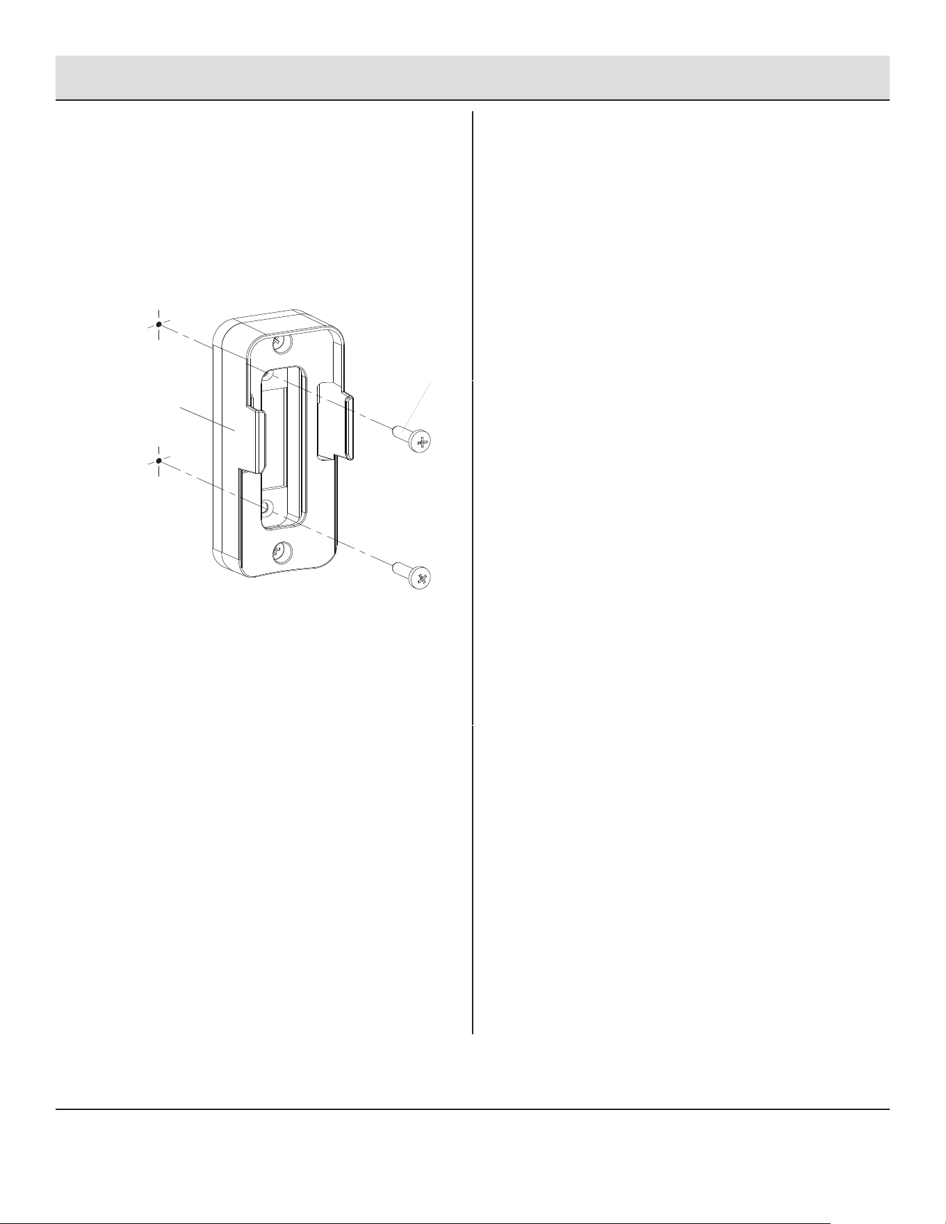
□ Place the remote control (H) on the remote control wall
mount (I) if needed.
□ Install the remote control wall mount (I) in to the desired
location, using the two mounting screws (GG) provided.
Installing the Remote Control
Wall Mount
GG
I
15
Operation
1
Using the Remote Control
2
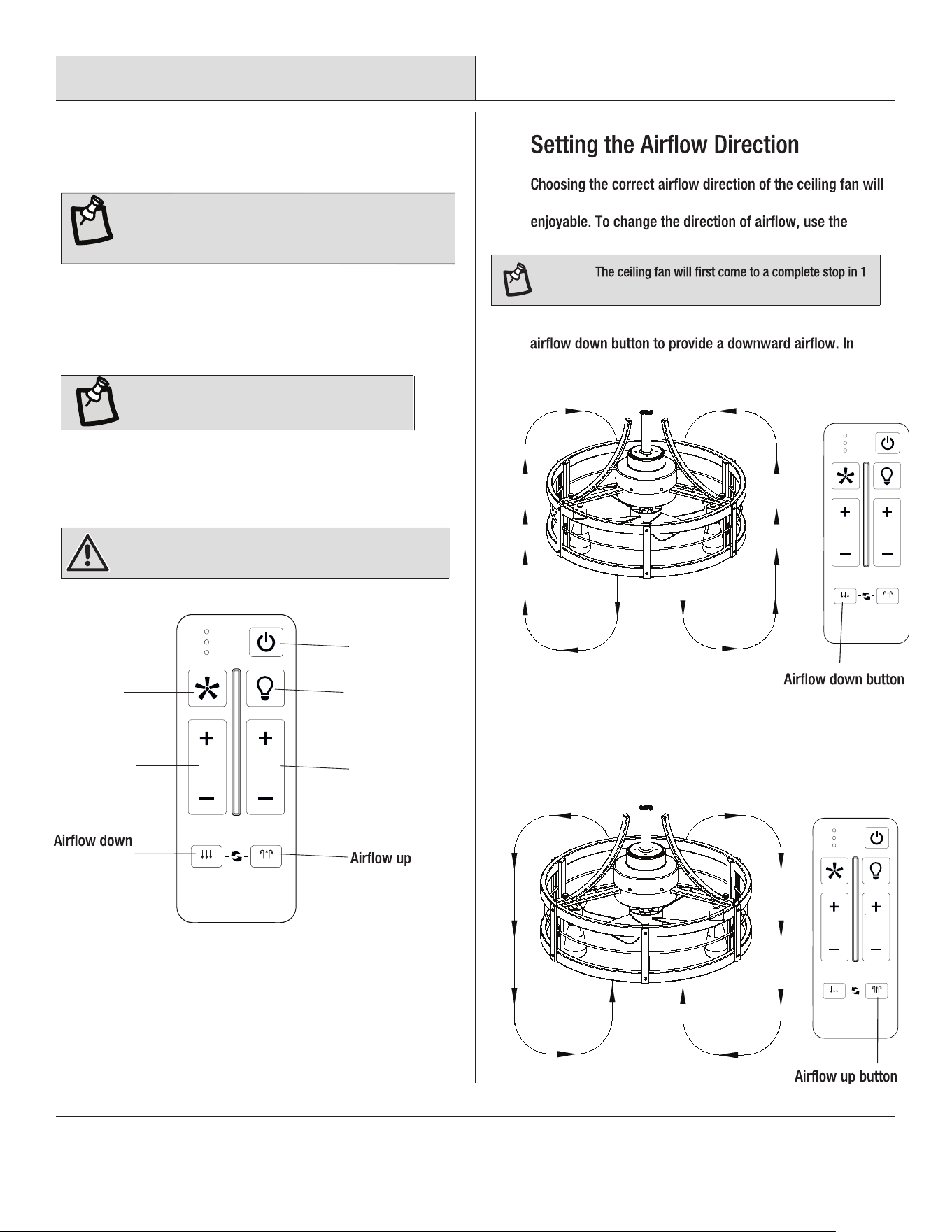
□ To turn the fan on and off, press and release the fan power
button. Press the fan speed adjusting button to set the fan
speed. There are three speed settings to the fan and the
number of lights on indicates the chosen speed.
(Model No. EHU-659TRF )
NOTE: If you have not already done so, restore power to the
room and wall switch, then make sure the wall switch
controlling the fan is turned on. The remote control (H) will
have no effect on the fan if the switch is turned off.
ALL
ON / OFF ON / OFF
3 SPEED BRIGHTNESS
FAN DIRECTION
HOLD 3 SEC.
SUMMER WINTER
Power button
Light
power button
Fan power
button
Fan speed
adjusting
button
button
Light
dimming
NOTE: The brightness of the fan light can only be
controlled by the remote control (H). A wall-mounted
dimmer switch will not change the light’s brightness.
HOMEDEPOT.COM/HOMEDECORATORS
Please contact 1-800-986-3460 for further assistance.
□ Press the Power button to power on.
□
To turn the light on and off, press and release the light
power button. Press the light dimming button to control
the brightness of the light.
WARNING: Do not leave the fan unattended when in use.
Always switch power off at service panel and lock the
service disconnecting means when not in use.
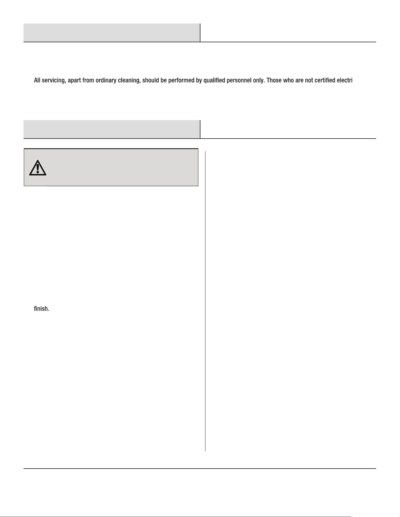
□
enhance the fan’s performance and make its use more
remote control (H).
□ Aim the remote control (H) at the fan position and press the
warmer weather, this direction will provide a constant
breeze, creating a wind chill effect for the room’s occupants.
NOTE:
or 2 seconds before changing the fan’s direction.
ALL
ON / OFF ON / OFF
3 SPEED BRIGHTNESS
FAN DIRECTION
HOLD 3 SEC.
SUMMER WINTER
□ In cooler weather, aim and press the AIRFLOW UP button on
remote control (H) to provide an upward direction of air travel.
This will help circulate warm air off the ceiling and back down
into the room.
ALL
ON / OFF ON / OFF
3 SPEED BRIGHTNESS
FAN DIRECTION
HOLD 3 SEC.
SUMMER WINTER
16
Maintenance
□ Due to the natural movement of a ceiling fan, connections can become loose over time. Check all the ceiling fan’s connections (not
including the electrical connections) at least twice a year.
□ The fan has permanently lubricated sealed bearings, therefore no further lubrication is required.
□
cians
should not disassemble, repair or rebuild the fan.
Care and Cleaning
□ Clean your fan periodically to help maintain its new appearance
over time.
□ Slightly moisten a cloth and then wipe off the surfaces of the fan.
Use only a soft brush or lint-free cloth to avoid scratching the
□ In order to remove the dust from the grille, use a vacuum cleaner
or a small brush.
□ After cleaning, reinstall the fan as previously installed and fasten
all the securing screws. Do not blend the blades.
□ When shipped, the blade and guard on the fan are preassembled.
□
Do not use any water for cleaning metal surfaces. Do not allow
water to drip on or enter into fan guard, as this could damage the
motor or cause an electrical shock.
□ Do not use a cleaning solution that is harmful to paints or plastics.
Avoid using solvents when cleaning plastic parts. Most plastics
are susceptible to damage from various types of commercial
solvents and can be damaged by their use. Do not use any of the
following as a cleaner: brake uids, gasoline, petroleum-based
products, penetrating oils, thinner, benzene, etc.
□ Only use the original manufacturer’s replacement parts, accessories and attachments.
□ After servicing, any safety device (including grilles and blades) must be reinstalled or remounted as previously installed.
WARNING:
Always switch power off at the service panel and
lock the service disconnecting means when not in use, before
moving fan from one location to another, before putting on or
taking off parts, and before cleaning or performing maintenance.
17
Troubleshooting
Problem Solution
Fan will not start. □ Wall switch is turned off. Turn wall switch on.
□ Circuit breaker is tripped or fuse is blown. Reset circuit breaker
or replace fuse.
□ Ceiling fan wiring is incorrect. Check the ceiling fan’s electrical
connections. If you are unable to detect the problem, consult a
Fan is noisy.
Fan wobbles.
Remote control is not working.
Remote control and fan are working, but lights do not work.
□ Some noise is natural during the break-in period of the fan.
Allow a minimum 24 hours break-in period. Most noises
associated with a new fan will be resolved during this time.
□ Ceiling fan housing screws are loose. Make sure all housing
screws are snugly tightened.
□ Blade set screw is loose. Retighten the blade set screw.
□ Wall switch is turned off. Turn wall switch on.
□ Remote batteries are dead. Replace the batteries in the remote
control.
□ Wall switch has solid-state speed controls. Do not use a wall
switch that has variable speed control (i.e. a dimmer switch).
□ The remote control and the receiver are not paired successfully.
Reset following the method under step 12 Preparing the Remote
Control of the Installation section until the beep is played.
□ Lighting wiring is incorrect. Check the light’s electrical
connections. If you are unable to detect the problem, consult a
□ LED bulbs are broken. Replace the bulbs.
□ Pivot ball is not captured in slot on fan mounting bracket. Refer
to the instructions under step 6 Attaching the Fan to the
Electrical Box of the Installation section to be sure the ceiling fan
is hung correctly.
□ Outlet box is not securely fastened to the ceiling joists. Tighten
the outlet box screws or use longer screws, if needed, to fasten
securely.
WARNING: Turn off power to room and wall switch by removing fuses or turning off circuit breakers as needed before attempting any repairs
to the ceiling fan or the electrical connections. Failure to do so can cause serious personal injury.
HOMEDEPOT.COM/HOMEDECORATORS
Please contact 1-800-986-3460 for further assistance.
18
FCC Statement
Caution
□
This equipment has been tested and found to comply with the limits for a Class B digital device, pursuant to Part 15 of the FCC Rules. These
limits are designed to provide reasonable protection against harmful interference in a residential installation. This equipment generates,
uses and can radiate radio frequency energy and, if not installed and used in accordance with the instructions, may cause harmful
interference to radio communications. However, there is no guarantee that interference will not occur in a particular installation. If this
equipment does cause harmful interference to radio or television reception, which can be determined by turning the equipment off and on,
the user is encouraged to try to correct the interference by one or more of the following measures:
equipment.
This device complies with Part 15 of the FCC Rules. Operation is subject to the following two conditions:
The following responsible party designated in FCC §2.909 is responsible for this declaration:
□ Increase the separation between the equipment and receiver.
□ Connect the equipment into an outlet on a circuit different from that to which the receiver is connected.
□ Consult the dealer or an experienced radio/TV technician for help.
Reorient or relocate the receiving antenna.
□
□ Remote Control Model Number: EHU-659TRF
□ Company Name: CM Development Inc.
□ Company Address: P.O. Box 90962, CA 91715, USA
□ Telephone Number: 562-283-8103
Fan Model Number: SFL-550R, SFL-550S
□ This device may not cause harmful interference, and
□ this device must accept any interference received, including interference that may cause undesired operation.

Questions, problems, missing parts? Before returning to the store,
call Home Decorators Collection Customer Service
8 a.m. - 7 p.m., EST, Monday - Friday, 9 a.m.- 6 p.m., EST, Saturday
1-800-986-3460
HOMEDEPOT.COM/HOMEDECORATORS
Retain this manual for future use.