
For portable spray applications of water-based and oil-based
non-flammable architectural paints and coatings only. For Household Use Only.
Not approved for use in explosive atmospheres or hazardous (classified) locations.
Important Safety Instructions
Read all warnings and instructions in this manual, and on the unit, including the power
cord, before using the equipment. Be familiar with the controls and the proper usage
of the equipment. Save these instructions.
Important Medical Information
Read the medical alert card provided with the gun. It contains injection injury
treatment information for a doctor. Keep it with you when operating the equipment.
3A9014C
EN
Owners Manual
Project Series Paint Sprayers
Before You Spray
2 3A9014C
Before You Spray
Review Warnings for Important Safety Information
Important! Read carefully and practice good safety habits.
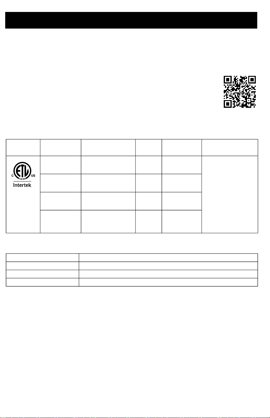
Models
Online Resources
Model Name Voltage Description
Maximum Working
Pressure
110474
Certified to
CAN/CSA
C22.2 No. 68
Conforms to
UL 1450
26D280
CAN280
TrueCoat 360
120V Single Speed
2000 psi
(
13.8 MPa, 138 bar)
26D281
CAN281
TrueCoat 360 DS
120V Dual Speed
26D282
CAN282
TrueCoat 360 DSP
120V
Dual Speed
Premium
26D283
CAN283
TrueCoat 360 VSP
120V
Variable
Speed
Premium
Visit Our Website: graco.com/homeowner
Operational Videos: graco.com/homeeducationcenter
Manuals: graco.com/homeownersupport
Parts Online: graco.com/homeownerparts
Operational Videos
http://graco.com/HomeEducationCenter
Important User Information
3A9014C 3
Important User Information
Thank You for Your Purchase!
Congratulations! You have purchased a high-quality paint sprayer made by Graco Inc. This
sprayer is designed to provide superior spray performance with water-based and oil-based
(mineral spirit-type) architectural paints and coatings. This user information is intended to help
you understand the types of materials that can be used with your sprayer.
Please read the information on the material container label to determine if it can be used with
your sprayer. Ask for a Safety Data Sheet (SDS) from your supplier. The container label and
SDS will explain the contents of the material and the specific precautions related to it.
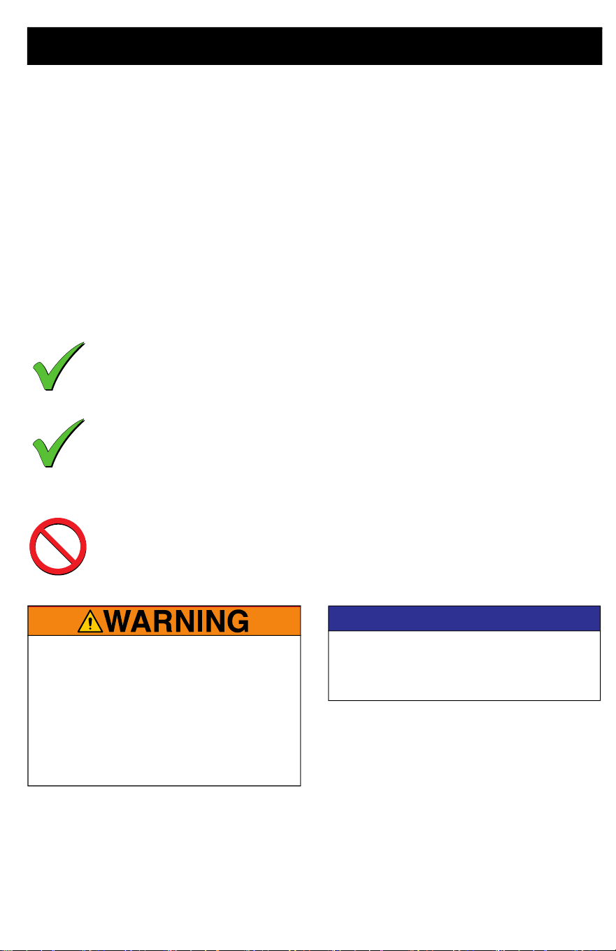
Paints, coatings and clean-up materials generally fit
into one of the following 3 basic categories:
WATER-BASED: The container label should indicate that the material can be
cleaned up with soap and water. Your sprayer is compatible with this type of
material. Your sprayer is NOT compatible with harsh cleaners such as chlorine
bleach.
OIL-BASED: The container label should indicate that the material is
COMBUSTIBILE and can be cleaned up with mineral spirits or paint thinner. The
SDS must indicate that the flash point of the material is above 100° F. Your sprayer
is compatible with this type of material. Use oil-based material outdoors or in a
well-ventilated indoor area with a flow of fresh air. See the safety warnings in this
manual.
FLAMMABLE: This type of material contains flammable solvents such as xylene,
toluene, naphtha, MEK, lacquer thinner, acetone, denatured alcohol, and
turpentine. The container label should indicate that this material is
FLAMMABLE. This type of material is NOT compatible with your sprayer
and CANNOT be used.
FIRE AND EXPLOSION HAZARD
• Use only non-flammable or
water-based materials, or
non-flammable paint thinners. Do not
use materials having flash points lower
than 100° F (38° C). This includes, but is
not limited to, acetone, xylene, toluene,
or naphtha. For more information about
your material, request Safety Data
Sheets (SDSs) from the supplier.
NOTICE
Your sprayer is NOT compatible with harsh
cleaners such as chlorine bleach. Using
these cleaners will cause damage to the
sprayer.

Contents
4 3A9014C
Contents
Before You Spray . . . . . . . . . . . . . . . . . . . . . . . . . . . . . . . . . . . . . . . . . . 2
Important User Information . . . . . . . . . . . . . . . . . . . . . . . . . . . . . . . . . 3
Contents . . . . . . . . . . . . . . . . . . . . . . . . . . . . . . . . . . . . . . . . . . . . . . . . . 4
Warnings . . . . . . . . . . . . . . . . . . . . . . . . . . . . . . . . . . . . . . . . . . . . . . . . 5
Know Your Sprayer . . . . . . . . . . . . . . . . . . . . . . . . . . . . . . . . . . . . . . . . 9
Know Your Controls . . . . . . . . . . . . . . . . . . . . . . . . . . . . . . . . . . . . . . 10
Setup . . . . . . . . . . . . . . . . . . . . . . . . . . . . . . . . . . . . . . . . . . . . . . . . . . 11
Pressure Relief Procedure . . . . . . . . . . . . . . . . . . . . . . . . . . . . . . . 11
Cup Fill . . . . . . . . . . . . . . . . . . . . . . . . . . . . . . . . . . . . . . . . . . . . . . 11
Startup . . . . . . . . . . . . . . . . . . . . . . . . . . . . . . . . . . . . . . . . . . . . . . . . . 14
Spraying . . . . . . . . . . . . . . . . . . . . . . . . . . . . . . . . . . . . . . . . . . . . . . . . 16
Spray Tip Orientation . . . . . . . . . . . . . . . . . . . . . . . . . . . . . . . . . . . 16
Spray Pattern Quality . . . . . . . . . . . . . . . . . . . . . . . . . . . . . . . . . . . 17
Spray Angle . . . . . . . . . . . . . . . . . . . . . . . . . . . . . . . . . . . . . . . . . . 17
Aiming Sprayer . . . . . . . . . . . . . . . . . . . . . . . . . . . . . . . . . . . . . . . . 17
Triggering Timing . . . . . . . . . . . . . . . . . . . . . . . . . . . . . . . . . . . . . . 17
Reversible Spray Tips . . . . . . . . . . . . . . . . . . . . . . . . . . . . . . . . . . . 18
Spray Tip Removal . . . . . . . . . . . . . . . . . . . . . . . . . . . . . . . . . . . . . 18
Spray Tip Installation . . . . . . . . . . . . . . . . . . . . . . . . . . . . . . . . . . . 18
Clear Tip Clogs . . . . . . . . . . . . . . . . . . . . . . . . . . . . . . . . . . . . . . . . 19
Cup Refills . . . . . . . . . . . . . . . . . . . . . . . . . . . . . . . . . . . . . . . . . . . 20
Pause in Spraying . . . . . . . . . . . . . . . . . . . . . . . . . . . . . . . . . . . . . . 20
Cleanup . . . . . . . . . . . . . . . . . . . . . . . . . . . . . . . . . . . . . . . . . . . . . . . . 21
Fluid Compatibility . . . . . . . . . . . . . . . . . . . . . . . . . . . . . . . . . . . . . 21
Static Grounding Instructions (Oil-Based Materials) . . . . . . . . . . . 21
Cleaning Sprayer . . . . . . . . . . . . . . . . . . . . . . . . . . . . . . . . . . . . . . 22
Storage . . . . . . . . . . . . . . . . . . . . . . . . . . . . . . . . . . . . . . . . . . . . . . . . . 24
Recycling and Disposal . . . . . . . . . . . . . . . . . . . . . . . . . . . . . . . . . . . 25
End of Product Life . . . . . . . . . . . . . . . . . . . . . . . . . . . . . . . . . . . . . 25
Troubleshooting . . . . . . . . . . . . . . . . . . . . . . . . . . . . . . . . . . . . . . . . . 26
Replacement Parts . . . . . . . . . . . . . . . . . . . . . . . . . . . . . . . . . . . . . . . 30
Single Speed, Dual Speed, Dual Speed Premium . . . . . . . . . . . . . 30
Parts List- Single Speed, Dual Speed, Dual Speed Premium . . . . 31
Replacement Parts . . . . . . . . . . . . . . . . . . . . . . . . . . . . . . . . . . . . . . . 32
Variable Speed Premium . . . . . . . . . . . . . . . . . . . . . . . . . . . . . . . . 32
Parts List- Variable Speed Premium . . . . . . . . . . . . . . . . . . . . . . . . 33
Technical Specifications . . . . . . . . . . . . . . . . . . . . . . . . . . . . . . . . . . . 34
Graco Standard Warranty . . . . . . . . . . . . . . . . . . . . . . . . . . . . . . . . . . 35
Warnings
3A9014C 5
Warnings
The following warnings are for the setup, use, grounding, maintenance, and repair of this
equipment. The exclamation point symbol alerts you to a general warning and the hazard
symbols refer to procedure-specific risks. When these symbols appear in the body of this
manual or on warning labels, refer back to these Warnings. Product-specific hazard symbols
and warnings not covered in this section may appear throughout the body of this manual where
applicable.
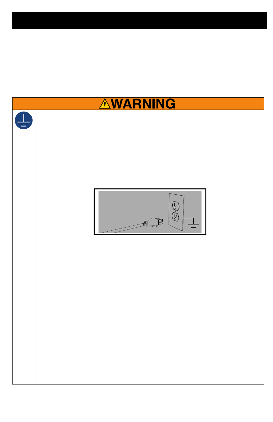
GROUNDING INSTRUCTIONS
This product must be grounded. In the event of an electrical short circuit, grounding
reduces the risk of electric shock by providing an escape wire for the electric current.
This product is equipped with a cord having a grounding wire with an appropriate
grounding plug. The plug must be plugged into an outlet that is properly installed
and grounded in accordance with all local codes and regulations.
• Improper installation of the grounding plug is able to result in a risk of electric
shock.
• This product is for use on a nominal 120 V circuit and has a grounding plug
similar to the plugs illustrated in the figure below.
• Only connect the product to an outlet having the same configuration as the
plug.
• Do not modify the plug provided. If it does not fit the outlet, have the proper
outlet installed by a qualified electrician.
• Do not use a 3-to-2 adapter with this product.
• When repair or replacement of the cord or plug is required, do not connect the
grounding wire to either power terminal.
• The wire with insulation having an outer surface that is green with or without
yellow stripes is the grounding wire.
• Check with a qualified electrician or serviceman when the grounding
instructions are not completely understood, or when in doubt as to whether the
product is properly grounded.
Extension Cords:
• Use only a 3-wire extension cord that has a grounding plug and a grounding
receptacle that accepts the plug on the product.
• Make sure your extension cord is not damaged.
• If an extension cord is necessary, use 12 AWG (2.5 mm
2
) minimum to carry the
current that the product draws. An undersized cord results in a drop in line
voltage and loss of power and overheating.
ti3509b
Warnings
6 3A9014C
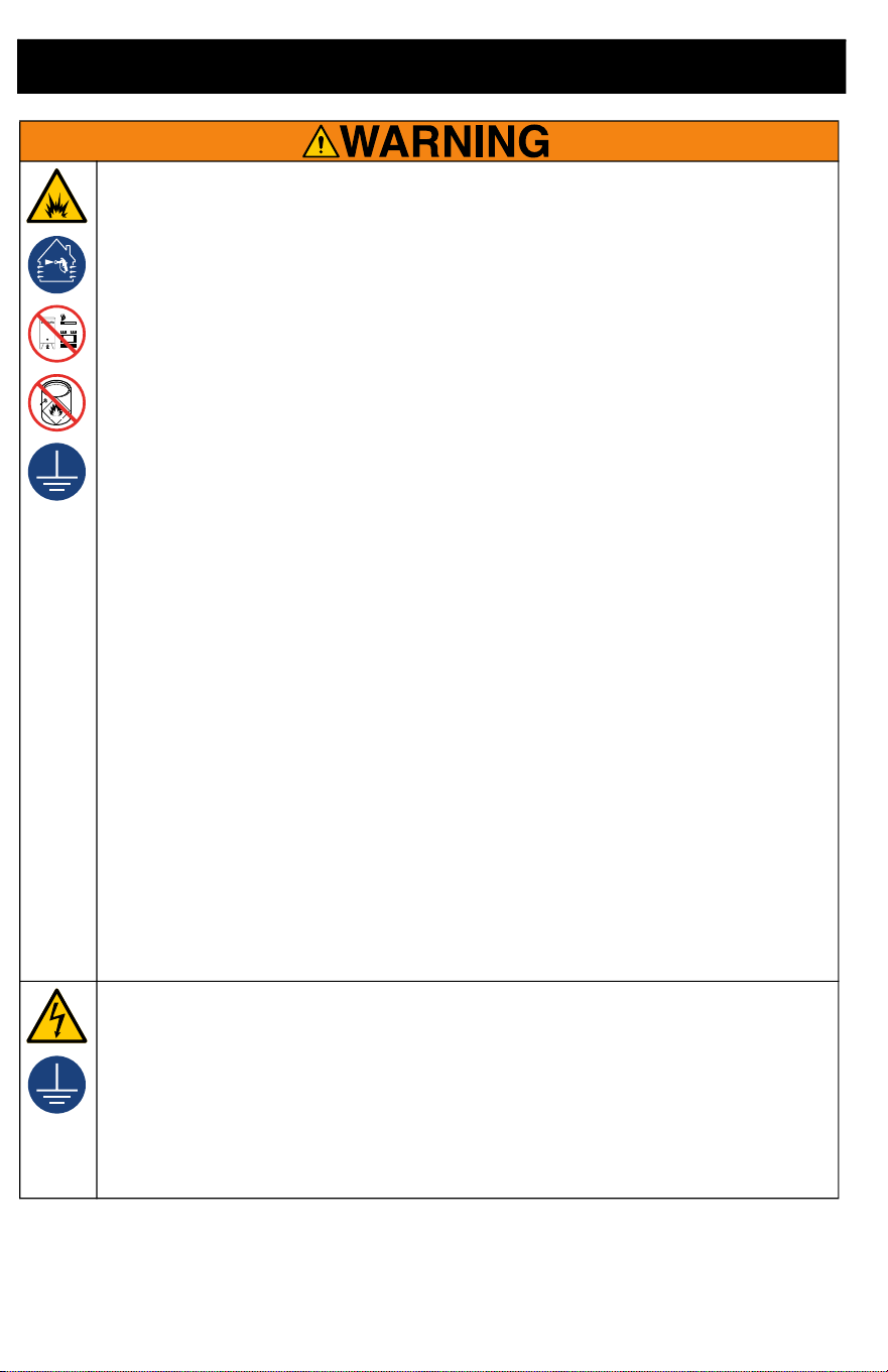
FIRE AND EXPLOSION HAZARD
Flammable fumes, such as solvent and paint fumes, in work area can ignite or
explode. To help prevent fire and explosion:
• Do not spray or clean with materials having flash points lower than 100°F (38°C).
Use only non-flammable or water-based materials, or non-flammable paint
thinners. For complete information about your material, request the Safety Data
Sheets (SDSs) from the material distributor or retailer.
• Do not spray combustible materials near an open flame or sources of ignition
such as cigarettes, motors, and electrical equipment.
• Paint or solvent flowing through the equipment is able to result in static
electricity. Static electricity creates a risk of fire or explosion in the presence of
paint or solvent fumes. All parts of the spray system, including the sprayer and
objects in and around the spray area shall be properly grounded to protect
against static discharge and sparks.
• Verify that all containers and collection systems are grounded to prevent static
discharge. Do not use pail liners unless they are anti-static or conductive.
• Connect to a grounded outlet and use grounded extensions cords. Do not use
a 3-to-2 adapter.
• Stop operation immediately if static sparking occurs or you feel a shock. Do
not use equipment until you identify and correct the problem.
• Do not use a paint or a solvent containing halogenated hydrocarbons.
• Keep spray area well-ventilated. Keep a good supply of fresh air moving
through the area.
• Sprayer generates sparks. Keep pump assembly in a well-ventilated when
spraying, flushing, cleaning, or servicing.
• Do not smoke in the spray area or spray where sparks or flame is present.
• Do not operate light switches, engines, or similar spark producing products in
the spray area.
• Keep area clean and free of paint or solvent containers, rags, and other
flammable materials.
• Know the contents of the paints and solvents being sprayed. Read all Safety
Data Sheets (SDSs) and container labels provided with the paints and solvents.
Follow the paint and solvent manufacturer's safety instructions.
• Keep a working fire extinguisher in the work area.
ELECTRIC SHOCK HAZARD
This equipment must be grounded. Improper grounding, setup, or usage of the
system can cause electric shock.
• Turn off and disconnect power cord before servicing equipment.
• Connect only to grounded electrical outlets.
• Use only 3-wire extension cords.
• Ensure ground prongs are intact on power and extension cords.
• Do not expose to rain. Store indoors.
Warnings
3A9014C 7
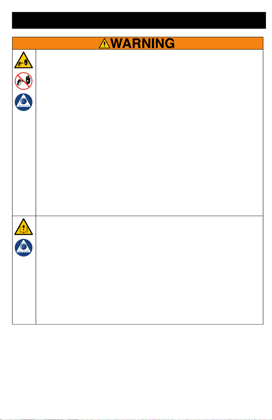
SKIN INJECTION HAZARD
High-pressure spray is able to inject toxins into the body and cause serious injury
that can result in amputation. In the event that injection occurs, get immediate
surgical treatment.
• Do not aim the gun at, or spray any person or animal.
• Keep hands and other body parts away from the discharge. For example, do not
try to stop leaks with any part of the body.
• Always use the spray tip guard. Do not spray without spray tip guard in place.
• Use Graco spray tips.
• Use caution when cleaning and changing spray tips. In the case where the spray
tip clogs while spraying, follow the Pressure Relief Procedure for turning off
the unit and relieving the pressure before removing the spray tip to clean.
• Equipment maintains pressure after power is shut off. Do not leave the
equipment energized or under pressure while unattended. Follow the Pressure
Relief Procedure when the equipment is unattended or not in use, and before
servicing, cleaning, or removing parts.
• Check parts for signs of damage. Replace any damaged parts.
• This system is capable of producing 2000 psi (138 bar, 13.8 MPa). Use Graco
parts or accessories that are rated a minimum of 2000 psi (138 bar, 13.8 MPa).
• Verify that all connections are secure before operating the unit.
• Know how to stop the unit and bleed pressure quickly. Be thoroughly familiar
with the controls.
EQUIPMENT MISUSE HAZARD
Misuse can cause death or serious injury.
• Always wear appropriate gloves, eye protection, and a respirator or mask when
painting.
• Do not operate or spray near children. Keep children away from equipment at
all times.
• Do not overreach or stand on an unstable support. Keep effective footing and
balance at all times.
• Stay alert and watch what you are doing.
• Do not operate the unit when fatigued or under the influence of drugs or alcohol.
• Do not alter or modify equipment. Alterations or modifications may void agency
approvals and create safety hazards.
• Make sure all equipment is rated and approved for the environment in which you
are using it.
Warnings
8 3A9014C
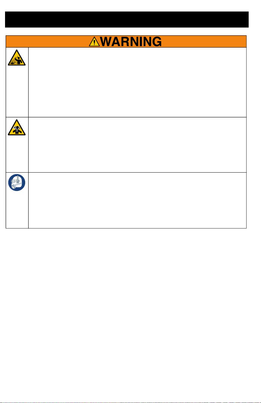
PRESSURIZED ALUMINUM PARTS HAZARD
Use of fluids that are incompatible with aluminum in pressurized equipment can
cause serious chemical reaction and equipment rupture. Failure to follow this
warning can result in death, serious injury, or property damage.
• Do not use 1,1,1-trichloroethane, methylene chloride, other halogenated
hydrocarbon solvents or fluids containing such solvents.
• Do not use chlorine bleach.
• Many other fluids may contain chemicals that can react with aluminum. Contact
your material supplier for compatibility.
TOXIC FLUID OR FUMES HAZARD
Toxic fluids or fumes can cause serious injury or death if splashed in the eyes or
on skin, inhaled, or swallowed.
• Read Safety Data Sheets (SDSs) to know the specific hazards of the fluids you
are using.
• Store hazardous fluid in approved containers, and dispose of it according to
applicable guidelines.
PERSONAL PROTECTIVE EQUIPMENT
Wear appropriate protective equipment when in the work area to help prevent
serious injury, including eye injury, hearing loss, inhalation of toxic fumes, and
burns. Protective equipment includes but is not limited to:
• Protective eyewear, and hearing protection.
• Respirators, protective clothing, and gloves as recommended by the fluid and
solvent manufacturer.

Know Your Sprayer
3A9014C 9
Know Your Sprayer
A Prime Knob
B
VacuValve
TM
C Spray Tip
D Speed Control (available on select
models only)
E Trigger
F
FlexLiner
TM
G Cup Support
H Cup Lid
J Funnel
K Strainer
L Strainer’s Air Tube
M Pump Filter
N Spray Tip Guard
P Spray Tip Holder
Q Power Cord

Know Your Controls
10 3A9014C
Know Your Controls
Prime Knob
The Prime Knob directs fluid to either the cup
or the Spray Tip. When priming, it is used to
purge air from the pump. Your sprayer will
not spray with air in the pump.
Turn Prime Knob down to PRIME position
when priming the sprayer or to relieve
system pressure.
Turn Prime Knob forward to SPRAY position
to spray fluid.
VacuValve
The VacuValve is used to evacuate air out of
the FlexLiner. This is necessary for the
sprayer to prime.
Spray Tip
The Spray Tip is the key to airless spray
technology. High pressure paint pumped
through the very small hole in the Spray Tip
comes out as a spray.
The Spray Tip has the ability to be reversed
and quickly clear clogs.
Trigger
The Trigger controls the operation of the
sprayer.
Speed Control
The Speed Control* allows you to slow down
or speed up when spraying.
*Available on select models only

Setup
3A9014C 11
Setup
Pressure Relief Procedure
Follow the Pressure Relief
Procedure whenever you see this
symbol.
1.
Turn Prime Knob down to PRIME position
to relieve pressure
.
Cup Fill
If spraying oil-based materials, review Fluid
Compatibility, page 21, and follow Static
Grounding Instructions (Oil-Based
Materials), page 21.
1. Insert one FlexLiner into the Cup
Support.
NOTE: Verify there is no damage to the top
sealing edge of the FlexLiner, such as a
crease or fold. If damaged it will leak air and
lose prime.
This sprayer builds up an internal
pressure of 2000 psi (138 bar, 13.8 MPa)
during use. Follow this Pressure Relief
Procedure whenever you stop spraying
and before cleaning, checking, servicing,
or transporting equipment to prevent
serious injury.
Use only water-based or oil-based
(mineral spirit-type) materials with a
flash point greater than 100° F (38° C).
Do not use materials which state
“FLAMMABLE” on the packaging. For
more information about your material,
request a Safety Data Sheet (SDS) from
distributor or retailer.
When spraying oil-based material, use
outdoors or in a well-ventilated indoor
area with a flow of fresh air.
Keep spray area well-ventilated. Keep a
good supply of fresh air moving through
the area.

Setup
12 3A9014C
2. Firmly tighten the Cup Lid onto the Cup
Support to ensure an airtight seal.
NOTE:
To ensure an airtight seal, the gasket
inside the Cup Lid is lubricated by the factory.
If lubrication has washed away, apply Seal
Lube (included) to the gasket.
3. Insert the Funnel into the Cup Lid, twist
to lock. Snap the Strainer into the Funnel
to strain your paint as you fill your cup.
4. The Strainer’s Air Tube will prevent paint
from overfilling the cup. Fill the cup as
follows:
a. Watching the Funnel (not the cup),
slowly pour paint into the Funnel.
When the paint stops draining
down, the cup is full.
NOTE: If the paint stops draining but you see
the cup is not full, use a stir stick to scrape
the captured debris on the top of the Strainer
until the paint resumes draining.
Funnel
Strainer

Setup
3A9014C 13
b. With the Funnel and Strainer still
attached to the cup, pour excess
paint from the Funnel back into the
paint can.
c. Lift up the Strainer and look to
verify you can see crossbars in the
bottom of the Funnel. If not, the
cup is overfilled. Pour excess paint
back into the paint can.
d. Remove the Funnel and Strainer
from the cup and hook on edge of
paint can.

Startup
14 3A9014C
Startup
1. Install the cup onto the sprayer as
follows:
a. Verify Pump Filter is installed and
clean.
b. Align VacuValve (on Cup Lid) with
Prime Knob (on sprayer).
c. Push cup assembly onto the
sprayer, twist to lock.
2. Prime the pump as follows:
a. Verify Prime Knob is pointed down
to PRIME position.
b. Plug sprayer into a grounded
power source.
c. Open the VacuValve cap and
gently squeeze the FlexLiner until
no more air bubbles appear in the
VacuValve.
NOTE: Tilt the sprayer such that the
VacuValve is the highest point so that all air
in the FlexLiner can be fully evacuated.

Startup
3A9014C 15
d. Continue to squeeze the FlexLiner
while pulling the Trigger for 10
seconds.
NOTE: This will purge all air from the pump
and cup. Paint will not spray out, but will
recirculate through the pump and back into
the cup.
e. When no more air bubbles appear
in the VacuValve, release the
Trigger and close the VacuValve
cap.
3. Turn Prime Knob forward to SPRAY
position. Verify Spray Tip is forward in
the SPRAY position.
4. Point the sprayer into a waste pail and
pull the Trigger for 5 seconds to spray
out storage fluid.
• To avoid pump damage, if the
sprayer does not spray after 5
seconds, STOP and repeat
STARTUP.
You are now ready to spray!
NOTE: For best results, to evacuate all
material from the FlexLiner when the material
is nearly gone, gently squeeze the bottom of
the FlexLiner to push the last of the material
up to the Cup Lid.
IMPORTANT! The motor has a built-in
feature to protect itself from overuse. If the
motor stops, the thermal switch has tripped.
The motor will operate normally after cooling
for 20-30 minutes.

Spraying
16 3A9014C
Spraying
1. Set the Speed Control to lowest
available setting.
2. Pointing at a piece of scrap cardboard,
pull the Trigger to test the spray pattern.
3. If needed, slowly increase the Speed
Control to the setting that produces a
good spray pattern.
NOTE: To minimize overspray, always spray
at the lowest speed setting that gives a good
spray pattern.
4. Adjust the sprayer’s distance from the
surface and your hand speed to achieve
the desired surface coverage.
Spray Tip Orientation
Adjust the Spray Tip Guard for the desired
vertical or horizontal spraying direction.
Use only water-based or oil-based
(mineral spirit-type) materials with a
flash point greater than 100° F (38° C).
Do not use materials which state
“FLAMMABLE” on the packaging. For
more information about your material,
request a Safety Data Sheet (SDS) from
distributor or retailer.
When spraying oil-based material, use
outdoors or in a well-ventilated indoor
area with a flow of fresh air.
Keep spray area well-ventilated. Keep a
good supply of fresh air moving through
the area.
To avoid serious injury from skin injection,
do not put your hand in front of the Spray
Tip when installing or removing the Spray
Tip and Tip Guard.
NO YES

Spraying
3A9014C 17
Spray Pattern Quality
A good spray pattern is evenly distributed
without voids or runs. Adjust sprayer Speed
Control (if available), hand speed, and distance
from the wall to get a good spray pattern.
If tails persist, material may need to be
thinned. If material needs to be thinned,
follow manufacturers recommendations.
Spray Angle
Use a piece of scrap cardboard to practice
these basic spraying techniques before you
begin spraying the surface.
• Hold sprayer 10-12 inches (25-30 cm)
from surface and aim straight at surface.
Tilting the sprayer to direct the spray
angle causes an uneven finish.
• Flex wrist to keep sprayer pointed
straight. Fanning sprayer to direct spray
at angle causes uneven finish.
NOTE: How fast you move the sprayer will
affect spray application. If material is
pulsating, you are moving too fast. If material
drips, you are moving too slow. See
Troubleshooting, page 26.
Aiming Sprayer
Aim the sprayer at the bottom edge of the
previous stroke, overlapping each stroke by
50%.
Triggering Timing
Pull Trigger after starting stroke. Release
Trigger before end of stroke. Sprayer must
be moving when Trigger is pulled and
released.
Spraying
18 3A9014C
Reversible Spray Tips
Your sprayer is shipped with wide and
narrow reversible Spray Tips.
• Blue Spray Tips are for spraying
paint and should be used with the
blue Pump Filter.
• Green Spray Tips are for spraying
stain and should be used with the
green Pump Filter (green tips and
filter are not included with all
models).
Spray Tip Removal
1. Turn Prime Knob down to PRIME
position to relieve system pressure.
2. Rotate Spray Tip 90 degrees.
3. Pull the Spray Tip straight out of the
Spray Tip Guard.
Spray Tip Installation
1. Align Spray Tip locking tab with the
locking tab slot in the Spray Tip Guard.
2. Push the Spray Tip all the way into the
Spray Tip Guard.
3. Rotate the Spray Tip to the SPRAY
position.
NOTE: Make certain the Spray Tip locking
tab is pushed all the way into the slot in the
Spray Tip Guard. You should not be able to
remove the Spray Tip from the Spray Tip
Guard when it is in the SPRAY or UNCLOG
positions.
To avoid serious injury from skin injection,
do not put your hand in front of the Spray
Tip when installing or removing the Spray
Tip and Tip Guard.
NOTICE
The Spray Tip Guard is permanently
attached to the sprayer. Removal will result
in damage to the sprayer.

Spraying
3A9014C 19
Clear Tip Clogs
In the event debris clogs the Spray Tip, the
sprayer is designed with a reversible Spray
Tip that quickly and easily clears the particles
without disassembling the sprayer.
1. Turn Prime Knob down to PRIME
position to relieve system pressure.
2. Reverse Spray Tip to UNCLOG position.
3. Set Speed Control to highest available
setting.
4. Point sprayer into waste pail, turn Prime
Knob forward to SPRAY position. Pull
Trigger for 5 seconds to clear clog.
NOTE: If Spray Tip is still clogged, you may
have to repeat steps 1-4, or replace with
replacement Spray Tip.
5.
Turn Prime Knob downward to PRIME
position.
Rotate Spray Tip back to
SPRAY position. Turn Prime Knob
forward to SPRAY position, and resume
spraying.
To avoid serious injury from skin injection,
do not put your hand in front of the Spray
Tip when installing or removing the Spray
Tip and Tip Guard.

Spraying
20 3A9014C
Cup Refills
1. Turn Prime Knob down to PRIME
position to relieve system pressure.
2. Remove cup assembly from sprayer.
Remove the Pump Filter and clean
debris from the filter screen.
3. Reinstall the Pump Filter into the pump.
Set sprayer on a rag.
4. Refill the cup following Cup Fill, page
11, steps 3 and 4. Then follow Startup,
page 14, instructions to proceed.
Pause in Spraying
Paint will dry quickly and cause clogs in the
sprayer. Follow these steps whenever you
pause spraying for 5 minutes to 2 hours.
1. Turn Prime Knob down to PRIME
position to relieve system pressure.
2. Unplug Power Cord.
3. Turn Spray Tip 90 degrees to seal orifice
from drying out.
4. Ensure sprayer is fully sealed. Ensure
VacuValve is closed and cup is attached
to sprayer with all air evacuated.
Cleanup
3A9014C 21
Cleanup
Fluid Compatibility
Oil or water-based materials
If spraying water-based materials, use
water for cleanup. If spraying oil-based
materials, use non-flammable mineral spirits
for cleanup.
• Switching between water-based and
oil-based materials can cause clogging
issues in the sprayer. Always clean
sprayer thoroughly with appropriate
cleaning fluid.
• It is recommended to thoroughly flush
the sprayer with non-flammable mineral
spirits prior to using oil-based
materials.
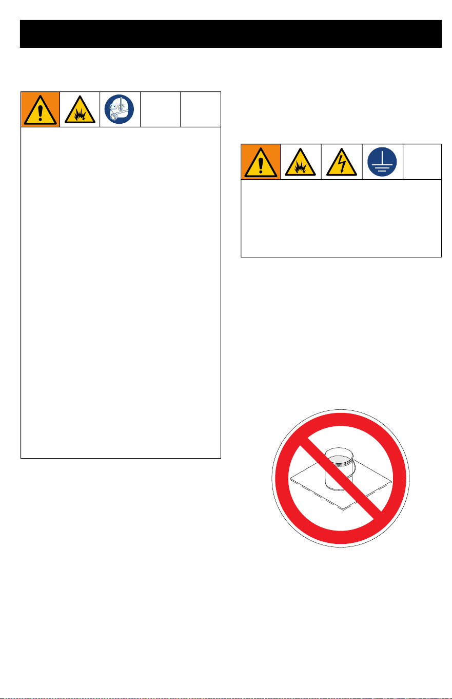
Static Grounding
Instructions (Oil-Based
Materials)
Always use a metal pail for oil-based
materials requiring flushing with compatible
oil-based flushing solvents when sprayer is
flushed or pressure is relieved.
Follow local code. Use only conductive
metal pails, placed on a grounded surface
such as concrete.
Do not place pail on a non-conductive
surface such as paper or cardboard which
interrupts grounding continuity.
Use only water-based or oil-based
(mineral spirit-type) materials with flash
point greater than 100° F (38° C). Do not
use materials which state “FLAMMABLE”
on the packaging. For more information
about your material, request a Safety Data
Sheet (SDS) from distributor or retailer.
Clean in a well-ventilated area. Keep a
good supply of fresh air moving through
the area.
To avoid serious injury or damage to
equipment, do not expose the sprayer
electronics to cleaning fluids. Keep
sprayer at least 10 in. (25 cm) above the
rim of the container when cleaning.
The equipment must be grounded to
reduce the risk of static sparking and
electric shock. An electric or static spark
can cause fumes to ignite or explode. An
improper ground can cause electric
shock. A good ground provides an escape
wire for the electric current.

Cleanup
22 3A9014C
Cleaning Sprayer
Cleaning your sprayer properly and after
every spray job is of the utmost importance!
Proper care and maintenance will make your
paint sprayer last and work for you trouble
free.
1. Turn Prime Knob down to PRIME
position to relieve system pressure.
2. Remove cup assembly from sprayer,
and remove Pump Filter. Set sprayer on
a rag.
3. Remove Cup Lid and pour extra paint
back into paint can. Clean all parts with
warm water.
NOTE: Be sure to clean inside the VacuValve
reservoir. If the VacuValve air hole becomes
clogged, use a paper clip to clean hole.
4. To circulate cleaning fluid, fill clean cup
assembly half-full of cleaning fluid and
reattach to sprayer.
a. Verify the Prime Knob is pointed
down to the PRIME position.
b. Set Speed Control to highest
setting available.
c. Turn the sprayer upside down and
trigger for 15 seconds.

Cleanup
3A9014C 23
5. To spray cleaning fluid, refill cup
assembly half-full of cleaning fluid and
reattach to sprayer.
a. Turn the Prime Knob forward to
SPRAY position and Spray Tip to
the UNCLOG position.
b. Turn the sprayer upside down and
trigger into a waste pail for 15
seconds.
c. Turn the Spray Tip to the SPRAY
position and trigger into a waste
pail for 15 seconds.
6. Repeat Cleanup steps as needed until
sprayer is clean.
7. Turn Prime Knob down to PRIME
position.
8. Unplug Power Cord.
9. Remove Spray Tip from Spray Tip
Guard.
10. Clean Spray Tip, Spray Tip Guard, and
Pump Filter with warm water and an old
toothbrush. Reinstall Spray Tip and
Pump Filter.

Storage
24 3A9014C
Storage
Pump Armor fluid protects the sprayer while
in storage. It helps protect sprayer against
startup issues on next use.
• Do not store the sprayer full of water.
• Do not allow water to freeze in sprayer.
• Do not store sprayer under pressure.
• Store sprayer indoors in a cool, dry
location.
• Never store sprayer with material in the
sprayer or cup.
1. Clean the sprayer and cup assembly.
See Cleanup, page 21.
2. Turn Prime Knob downward to PRIME
position.
3. Remove cup assembly from sprayer and
remove Pump Filter from pump.
4. Turn Prime Knob forward to SPRAY
position and Spray Tip to the UNCLOG
position.
5. With the sprayer upside down, pour
approximately 2 oz. (60 ml) Pump Armor
(included) into pump opening.
6. Install clean Pump Filter into pump.
7. Keep sprayer upside down and attach
cup assembly on to the sprayer.
8. With the sprayer remaining upside down
over a waste pail, pull the Trigger until
fluid first comes out of the Spray Tip and
then immediately let go of the Trigger
(approx. 1 second).
NOTE: Do not spray out all fluid. Pump is
now loaded with Pump Armor for storage.
9. Turn Prime Valve to PRIME position to
relieve system pressure and
immediately back to SPRAY position for
storage. Unplug Power Cord.
10. Replace child-resistant cap on Pump
Armor bottle and tighten securely for
next use.
NOTICE
Failure to store sprayer with Pump
Armor
TM
will result in operational problems
the next time you spray. Always fill the
sprayer with Pump Armor after cleaning.
Water left in the sprayer will corrode
and damage the pump.

Recycling and Disposal
3A9014C 25
Recycling and Disposal
End of Product Life
At the end of the product’s useful life,
dismantle and recycle it in a responsible
manner.
• Turn Prime Knob down to PRIME
position to relieve system pressure.
• Drain and dispose of fluids according to
applicable regulations. Refer to the
material manufacturer’s Safety Data
Sheet.
• Remove motors, batteries, circuit
boards, LCDs (liquid crystal displays),
and other electronic components.
Recycle according to applicable
regulations.
• Do not dispose of electronic
components with household or
commercial waste.
• Deliver remaining product to a recycling
facility.
Troubleshooting
26 3A9014C
Troubleshooting
Check everything in this Troubleshooting
Table before you bring the sprayer to an
authorized service center.
Sprayer Diagnostics
Problem Cause Solution
Sprayer makes sound
but no material is
sprayed when Trigger is
pulled
Spray Tip is clogged See Clear Tip Clogs, page 19.
Sprayer is not primed Repeat Start Up procedure to
ensure all air is evacuated from
the FlexLiner. See Startup, page
14.
Verify Cup Lid is tight. An under
tightened Cup Lid will allow air to
seep into the FlexLiner and
cause a loss of prime. Add Seal
Lube (included) to the Cup Lid
gasket to ensure an airtight seal.
If the sprayer sprays when
upside down by not upright,
there is likely still an air leak into
the cup. Try replacing the
FlexLiner and VacuValve (extra
of both included with sprayer).
Make certain there is only one
FlexLiner in the Cup Support.
Make certain there is no damage
to or debris on the top sealing
edge of the FlexLiner or Cup Lid
gasket.
Make certain all the air is out of
the FlexLiner and the VacuValve
cap is properly closed.
Make certain the cup assembly
is properly installed onto the
sprayer.
Clean sprayer. See Cleanup,
page 21.
Pump Filter is plugged Remove the Pump Filter from the
pump. Clean both sides of the
Pump Filter. While the Pump
Filter is removed, inspect and
ensure no dried paint debris is
collected inside the pump inlet.
Prime Knob is in PRIME position Turn Prime Knob forward to
SPRAY position.
Spray Tip is not in SPRAY position Turn Spray Tip to SPRAY
position.
No or low material in FlexLiner Refill FlexLiner. See Cup Fill,
page 11.
Troubleshooting
3A9014C 27
Sprayer makes no sound
when Trigger is pulled
Power supply Make certain the sprayer is
plugged into a grounded and
functional power source.
Motor has overheated Wait 20-30 minutes for motor to
cool.
Electronic control failure Replace electronic control.
Sprayer sprays with poor
results
Spray Tip is partially clogged See Clear Tip Clogs, page 19.
Spray Tip is not in correct position See Spray Tip Installation,
page 18.
Incorrect Spray Tip for application
of material
Install a different size Spray Tip.
See Reversible Spray Tips,
page 18.
Spray Tip is worn or damaged Replace Spray Tip.
Material being sprayed is aerated
and full of bubbles
Let material settle or change to
different material.
Material being sprayed is too cold Warm material.
Paint leaks from sprayer Pump has reached its maximum life Replace pump.
Paint leaks out of the cup
threads
Cup not properly seated Verify Cup Lid is tight. An under
tightened Cup Lid will allow air to
seep into the FlexLiner and
cause a loss of prime. Add Seal
Lube (included) to the Cup Lid
gasket to ensure an airtight seal.
Make certain there is only one
FlexLiner in the Cup Support.
Make certain there is no damage
to or debris on the top sealing
edge of the FlexLiner or Cup Lid
gasket.
Make certain the Cup Lid is
properly threaded to the Cup
Support. There should be no
threads visible when tight.
Avoid flexing or pushing on the
Cup Support when you evacuate
the air out of the FlexLiner.
Avoid pulling down on the
FlexLiner when you evacuate the
air out of the FlexLiner.
Replace FlexLiner.
Problem Cause Solution
Troubleshooting
28 3A9014C
Spray Pattern Diagnostics
Problem Cause Solution
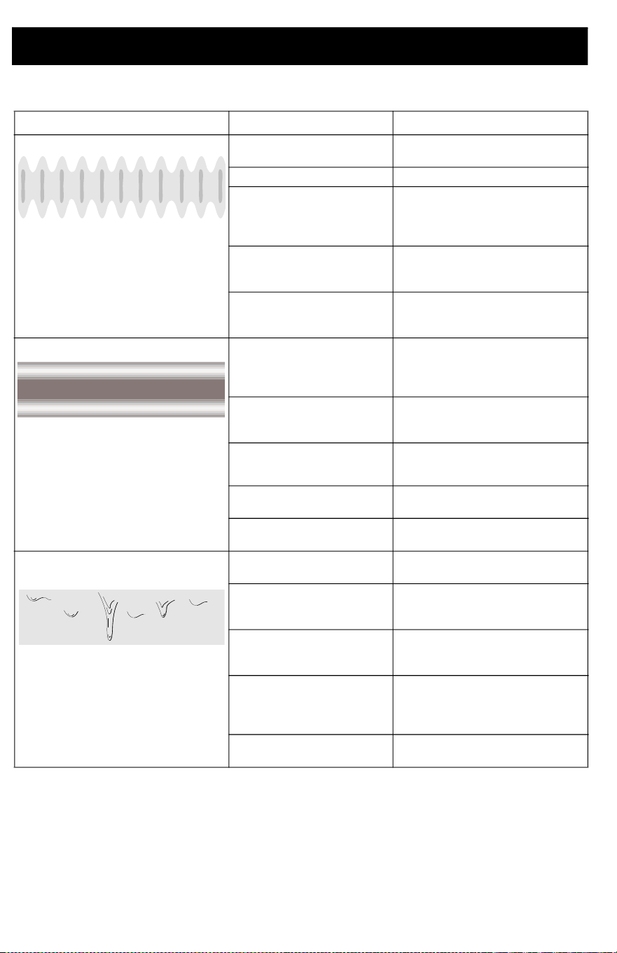
Spray pattern is pulsating: Operator is moving too
fast while spraying
Slow speed of movement.
Spray Tip is clogged See Clear Tip Clogs, page 19.
Material is difficult to
atomize
On models with Speed Control,
increase speed until desired
pattern is achieved. See
Spraying, page 16.
Sprayer is too far from
target surface
Hold sprayer farther away from
surface. See Spraying, page
16.
Incorrect Spray Tip for
application of material
Install a different size Spray Tip.
See Reversible Spray Tips,
page 18.
Spray pattern has tails: Speed Control is set too
low
On models with Speed Control,
increase speed until desired
pattern is achieved. See
Spraying, page 16.
Incorrect Spray Tip for
application of material
Install a different size Spray Tip.
See Reversible Spray Tips,
page 18.
Material may need to be
thinned
Thin material following paint
manufacturer's
recommendations.
Material not compatible
with sprayer
Change to different material.
Spray Tip is worn or
damaged
Replace Spray Tip.
Spray pattern has
dripping/sagging:
Operator is moving too
slowly while spraying
Move sprayer faster when
spraying.
Sprayer is too close to
target surface
Move sprayer away from
surface. See Spraying, page
16.
Holding Trigger while
changing spray direction
Release Trigger when changing
directions. See Spraying, page
16.
Speed Control is set too
high
On models with Speed Control,
decrease speed until desired
pattern is achieved. See
Spraying, page 16.
Spray Tip is worn or
damaged
Replace Spray Tip.
ti15524a
ti15526a

Troubleshooting
3A9014C 29
Spray pattern “spits” at the end or
beginning:
Excess material has
accumulated on Spray Tip
and Spray Tip Guard, or
Spray Tip is partially
plugged
Clean Spray Tip and Spray Tip
Guard. Clear Spray Tip. See
Clear Tip Clogs, page 19.
Spray Tip is not fully
inserted into Spray Tip
Guard
See Spray Tip Installation,
page 18.
Spray Tip is worn or
damaged
Replace Spray Tip.
Pump has reached its
maximum life
Replace pump.
Problem Cause Solution
ti15525a
ti15525a

Replacement Parts
30 3A9014C
Replacement Parts
Single Speed, Dual Speed, Dual Speed Premium

Replacement Parts
3A9014C 31
Parts List- Single Speed, Dual Speed, Dual Speed Premium
Ref. Sprayer Name
Order
Part No.
Description
1 All 18F756 Complete pump assembly includes 2, 3, 5, 6, 7, 8
2 All 16Y425 O-ring
3
All
18A886 Filter, pump, paint
18F209 Filter, pump, stain
5 All 117059 O-ring
6 All 17A402 Prime Pump/Spray valve includes qty. 1 of ref. 5
7 All 17A221 Kit, Prime Pump/Spray knob includes qty. 1 of ref. 8
8 All 119236 Screw, T-15 (torque 8-10 in-lb / 0.9-1.1 N•m)
9 All
18F520 Kit tips, paint includes 3 (CAN models order CANP20)
18F519 Kit tips, stain includes 3 (CAN models order CANS19)
10 All 16X880 Reciprocator assembly
12 Single Speed 17A224 Control, electronic, single speed, 120V includes motor, air
duct, power cord and switch
Dual Speed 17B653 Control, electronic, dual speed, 120V includes motor, air
duct, power cord and switch
13a Dual Speed 16X868 Switch, dual speed control
13b Single Speed 16X869 Plug, single speed
14 All 16W846 Support, 32 oz. cup
15 All 17A226 Kit, 32oz., FlexLiner (3-pack)
16 All 17R821
Kit, cup assembly includes 14, qty. 1 of ref. 15, 16a, 17, qty.
1 of ref. 18
16a All 17M879 Plug, cup lid, not shipped with sprayer (not shown)
17 All 18F759 Lid, cup includes qty. 1 of ref. 18
18 All 17P712 VacuValve cap, 3-pack
19 All 17A227 Kit, enclosure includes qty. 13 of ref. 8
20 All 16Y680 Label, USA
22 All 16Y678 Label, control
23 ▲ All 16Y636 Label, warning and model number, side (not shown)
24
Single Speed 18C037 Label, brand, TrueCoat 360
Dual Speed Premium 18C038 Label, brand, TrueCoat 360 DSP
Dual Speed 18C040 Label, brand, TrueCoat 360 DS
25 ▲ All models 17A198 Label, warning, cord (not shown)
26 Dual Speed Premium 18F449 Case, storage
30 All 18B057 Kit, funnel, strainer includes qty. 1 of ref. 2
31 All 25T467 Lubricant, seal lube
32 All 17K515 Label, A+ Service (not shown)
33 All 18B058 Spout, pour
- - ▲ All 179960 Label, medical alert card (not shown)
- - - All 243104 Pump Armor, 32 oz. (not shown)
- - - All 18C045 Tag, hang, tip (not shown) (CAN models order 18F613)
- - - All 17F518 Kit, 42 oz. cup (not shown)
- - - All 17F005 Kit, 42 oz. FlexLiner (3-pack) (not shown)
▲ Replacement safety labels, tags, and cards are available at no cost.

Replacement Parts
32 3A9014C
Replacement Parts
Variable Speed Premium

Replacement Parts
3A9014C 33
Parts List- Variable Speed Premium
Ref. Sprayer Name
Order
Part No.
Description
1 All 18F756 Complete pump assembly includes 2, 3, 5, 6, 7, 8
2 All 16Y425 O-ring
3 All
18A886 Filter, pump, paint
18F209 Filter, pump, stain
5 All 117059 O-ring
6 All 17A402 Prime Pump/Spray valve includes qty. 1 of ref. 5
7 All 17A221 Kit, Prime Pump/Spray knob includes qty. 1 of ref. 8
8 All 119236 Screw, T-15 (torque 8-10 in-lb / 0.9-1.1 N•m)
9 All
18F520 Kit tips, paint includes 3 (CAN models order CANP20)
18F519 Kit tips, stain includes 3 (CAN models order CANS19)
10 All 16X880 Reciprocator assembly
12 All 17F068
Control, electronic, variable speed, 120 V includes motor, air
duct, power cord and switch
13 All 17D844 Adapter, variable speed control
14 All 16W846 Support, cup, 32 oz.
15 All 17A226 Kit, 32 oz., FlexLiner (3-pack)
16 All 17R821
Kit, cup assembly includes 14, qty. 1 of ref. 15, 16a, 17, qty.
1 of ref. 18
16a All 17M879 Plug, cup lid, not shipped with sprayer (not shown)
17 All 18F759 Lid, cup includes qty. 1 of ref. 18
18 All 17P712 VacuValve cap, 3-pack
19 All 17A227 Kit, enclosure includes qty. 13 of ref. 8
20 All 16Y680 Label, USA
22 All 16Y678 Label, control
23 ▲ All 16Y636 Label, warning and model number, side (not shown)
24 All 18C042 Label, brand, TrueCoat 360 VSP
25 ▲ All 17A198 Label, warning, cord (not shown)
26 All 18F449 Case, storage
27 All 17F069
Kit, enclosure, variable speed includes sight glass, includes
13, 29, qty. 2 of ref 8
29 All 17D843 Sight glass
30 All 18B057 Kit, funnel, strainer includes qty. 1 of ref. 2
31 All 25T467 Lubricant, seal lube
32 All 17K515 Label, A+ Service (not shown)
33 All 18B058 Spout, pour
- - ▲ All 179960 Label, medical alert card (not shown)
- - - All 243104 Pump Armor, 32 oz (not shown)
- - - All 18C045 Tag, hang, tip (not shown) (CAN models order 18F613)
- - - All 17F518 Kit, 42 oz. cup (not shown)
- - - All 17F005 Kit, 42 oz. FlexLiner (3-pack) (not shown)
▲ Replacement safety labels, tags, and cards are available at no cost.
Technical Specifications
34 3A9014C
Technical Specifications
California Proposition 65
TrueCoat 360
U.S. Metric
Max Working Pressure 2000 psi
13.8 MPa, 138 bar
Maximum Amperage 2.5 Amps 2.5 Amps
Weight
TrueCoat 360, 360 DS/DSP 3.5 lb (18 in.cord) 1.6 kg (45 cm cord)
TrueCoat 360 VSP 3.75 lb (18 in.cord) 1.7 kg (45 cm cord)
Dimensions:
Length (All models) 12.50 in. 31.75 cm
Width (All models) 5.25 in. 13.34 cm
Height 360, 360 DS/DSP 9.75 in. 24.77 cm
Height 360 VSP 11.8 in. 29.97 cm
Storage Temperature Range ◆❖ 32° to 113° F 0° to 45° C
Operating Temperature Range ✓ 40° to 90° F 4° to 32° C
Storage Humidity Range 0% to 95% relative humidity, non-condensing
Electrical Power Requirement 120 Vac, 60 Hz, 15A, 1 phase
Duty Cycle 2/2 minutes
Maximum tip orifice 0.015 in. 0.38 mm
Wetted materials on all models: stainless steel, brass, polyethylene, carbide, nylon,
polypropylene, fluoroelastomer, acetal, aluminum
◆ Pump damage will occur if fluid freezes in pump.
❖ Damage to plastic parts may result if impact occurs in low temperature conditions.
✓ Changes in paint viscosity at very low or very high temperatures can affect sprayer
performance.
CALIFORNIA RESIDENTS
WARNING: Cancer and reproductive harm –
www.P65warnings.ca.gov.

Graco Standard Warranty
3A9014C 35
Graco Standard Warranty
Graco warrants all equipment referenced in this document which is manufactured by Graco and bearing
its name to be free from defects in material and workmanship on the date of sale to the original
purchaser for use. With the exception of any special, extended, or limited warranty published by Graco,
Graco will, for a period of twelve months from the date of sale, repair or replace any part of the
equipment determined by Graco to be defective. This warranty applies only when the equipment is
installed, operated and maintained in accordance with Graco’s written recommendations.
This warranty does not cover, and Graco shall not be liable for general wear and tear, or any
malfunction, damage or wear caused by faulty installation, misapplication, abrasion, corrosion,
inadequate or improper maintenance, negligence, accident, tampering, or substitution of non-Graco
component parts. Nor shall Graco be liable for malfunction, damage or wear caused by the
incompatibility of equipment with structures, accessories, equipment or materials not supplied by
Graco, or the improper design, manufacture, installation, operation or maintenance of structures,
accessories, equipment or materials not supplied by Graco.
This warranty is conditioned upon the prepaid return of the equipment claimed to be defective to an
authorized Graco distributor for verification of the claimed defect. If the claimed defect is verified, Graco
will repair or replace free of charge any defective parts. The equipment will be returned to the original
purchaser transportation prepaid. If inspection of the equipment does not disclose any defect in
material or workmanship, repairs will be made at a reasonable charge, which charges may include the
costs of parts, labor, and transportation.
THIS WARRANTY IS EXCLUSIVE, AND IS IN LIEU OF ANY OTHER WARRANTIES, EXPRESS OR
IMPLIED, INCLUDING BUT NOT LIMITED TO WARRANTY OF MERCHANTABILITY OR
WARRANTY OF FITNESS FOR A PARTICULAR PURPOSE.
Graco’s sole obligation and buyer’s sole remedy for any breach of warranty shall be as set forth above.
The buyer agrees that no other remedy (including, but not limited to, incidental or consequential
damages for lost profits, lost sales, injury to person or property, or any other incidental or consequential
loss) shall be available. Any action for breach of warranty must be brought within two (2) years of the
date of sale.
GRACO MAKES NO WARRANTY, AND DISCLAIMS ALL IMPLIED WARRANTIES OF
MERCHANTABILITY AND FITNESS FOR A PARTICULAR PURPOSE, IN CONNECTION WITH
ACCESSORIES, EQUIPMENT, MATERIALS OR COMPONENTS SOLD BUT NOT MANUFACTURED
BY GRACO. These items sold, but not manufactured by Graco (such as electric motors, switches, hose,
etc.), are subject to the warranty, if any, of their manufacturer. Graco will provide purchaser with
reasonable assistance in making any claim for breach of these warranties.
In no event will Graco be liable for indirect, incidental, special or consequential damages resulting from
Graco supplying equipment hereunder, or the furnishing, performance, or use of any products or other
goods sold hereto, whether due to a breach of contract, breach of warranty, the negligence of Graco, or
otherwise.
FOR GRACO CANADA CUSTOMERS
The Parties acknowledge that they have required that the present document, as well as all documents,
notices and legal proceedings entered into, given or instituted pursuant hereto or relating directly or
indirectly hereto, be drawn up in English. Les parties reconnaissent avoir convenu que la rédaction du
présente document sera en Anglais, ainsi que tous documents, avis et procédures judiciaires exécutés,
donnés ou intentés, à la suite de ou en rapport, directement ou indirectement, avec les procédures
concernées.

All written and visual data contained in this document reflects the latest product information available at
the time of publication. Graco reserves the right to make changes at any time without notice.
Original instructions. This manual contains English. MM 3A9014
Graco Headquarters: Minneapolis
International Offices: Belgium, China, Japan, Korea
GRACO INC. AND SUBSIDIARIES • P.O. BOX 1441 • MINNEAPOLIS MN 55440-1441 • USA
Copyright 2022, Graco Inc. All Graco manufacturing locations are registered to ISO 9001.
www.graco.com
Revision C, May 2022
Graco Information
For the latest information about Graco products, visit www.graco.com.
For patent information, see www.graco.com/patents.
TO PLACE AN ORDER, contact your Graco distributor or call 1-888-541-9788 to identify the nearest
distributor.