
Revision: Regulatory 01
March 2026
User Manual
™
#02

Copyright
Copyright 2026 Vexilar Inc. All rights reserved. No part of this publication may be
reproduced, transmitted, transcribed, stored in a retrieval system or translated into any
language or computer language, in any form or by any means—electronic, mechanical,
magnetic, optical, chemical, manual or otherwise—without the prior written permission of
Vexilar Inc.
All other logos, products, or company names mentioned in this User Manual may be
the registered trademarks or copyrights of their respective companies and are used for
informational purposes only.
Disclaimer
Vexilar Inc. makes no representations or warranties, either expressed or implied, with
respect to the content in this publication and specifically disclaims any warranties,
merchantability, or fitness for any particular purpose.
Further, Vexilar Inc. reserves the right to revise this publication and to make changes from
time to time in its content without the obligation to notify any person of such revision or
changes.
This User Manual aims to provide the most updated and accurate information to customers,
and thus all content may be modified from time to time without prior notice.
#02

Table of Contents
Chapter 1 Introduction ................................................................ 1
Basic Concept .....................................................................................................1
About this User Manual
......................................................................................1
Contact Us
..........................................................................................................2
Chapter 2 Get Started ................................................................. 3
Package Content ................................................................................................3
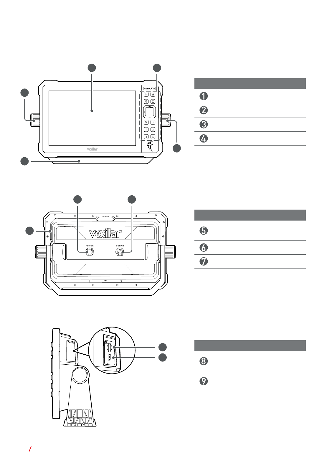
Overview
............................................................................................................. 4
Insert a microSD Card
.......................................................................................5
Mount the Head Unit
...........................................................................................6
Connect the Head Unit to Power
........................................................................6
Chapter 3 Use the Head Unit ....................................................... 7
Turn On/Off the Head Unit ..................................................................................7
Identify the Main Screen Layout
........................................................................7
Set the Language
...............................................................................................9
Set the Time
.......................................................................................................9
Set Up the Wi-Fi Network
................................................................................ 10
Cast the Screen to a Remote Display
............................................................... 10
Chapter 4 Appendixes ................................................................11
Appendix A: Specifications ............................................................................... 11
Appendix B: FCC Statement
............................................................................. 12
Appendix C: ISED Statement
............................................................................ 13
#02

1
Introduction
1 Introduction
The VEXILAR
®
VISION X10 Fish Finder is a 10.1-inch sonar unit designed to support
both open-water and ice-fishing operations, integrating multi-frequency sonar, wireless
accessory connectivity, GPS positioning, and real-time imaging functions to enhance target
detection accuracy and overall unit usability.
CAUTION
All route and navigation lines shown on the screen provide only general guidance
and are not intended for precise navigation. Operators must rely on official
navaids, waterway conditions, and sound seamanship to avoid hazards, damage,
or injury. This is a supplemental aid only and must not be used as the sole means
of navigation; users are responsible for employing multiple navigational methods
to ensure safe operation.
Basic Concept
Acquaint yourself with the basic operating concepts before using the sonar unit to improve
overall fishing performance.
Range Control
Depth Range determines the maximum depth at which the unit can detect and display
the bottom. Select the shallowest range that still shows the bottom to maximize screen
resolution and improve target visibility.
Gain Control
Gain adjusts the amplification of return sonar signals. Higher gain increases visible
information; lower gain reduces unwanted clutter. Set gain as low as possible while still
showing useful detail. Increasing gain expands the effective detection area but may reduce
clarity in cluttered environments.
Interference Rejection
Interference Rejection filters out sonar noise from nearby depth sounders. Enable this
feature when operating near other sonar systems or when excessive random signal flashes
appear on the display.
About this User Manual
Information contained in this manual is correct at the time of release and subject to change
without notice. Visit us to download the latest version of this manual: www.vexilar.com.
• Screen images and icons in this manual are simulated for illustrative purposes only.
Actual displays may vary.
#02

2 Introduction
• In this User Manual, the following graphic symbols and texts are used to alert you to
important information. Make sure you have read all the notes, cautions, and warnings
mentioned in this user manual.
NOTE
Useful tips or additional information that help you get better use of this device.
CAUTION
Notices describing actions or conditions that may damage your product and
consequently void your warranty or lose the unit data.
WARNING
Instructions that must be followed. Failure to observe them can cause damage
to your product or result in personal injuries.
Contact Us
For product support and service information, visit www.vexilar.com.
#02
3
Get Started
2 Get Started
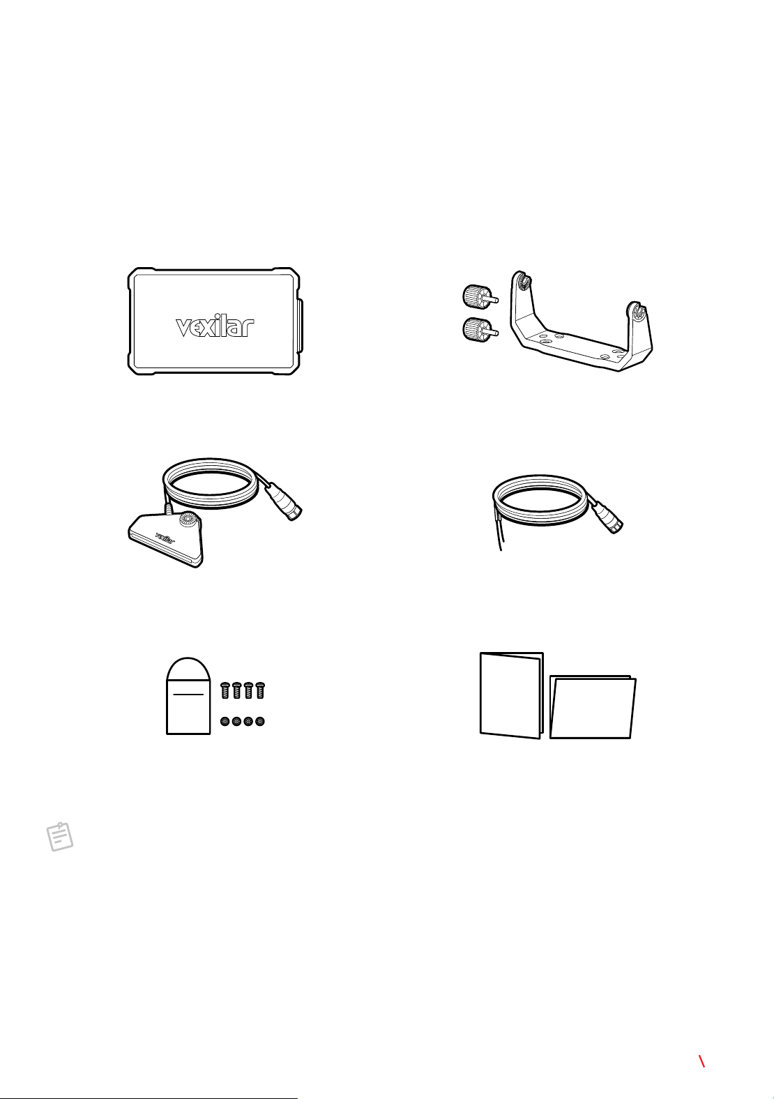
Package Content
Check the sales package for the following items. If any item is missing or damaged, contact
your place of purchase immediately.
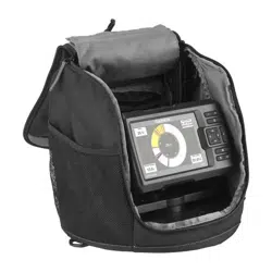
Head unit
(with protective cover)
Unit stand
(with 2 gimbal knobs)
Transducer
(with sonar connector)
Power cable
(with connector and leads)
Quick
Start
Guide
Installation Guide
Mounting hardware
(4 bolts & 4 nuts)
User documentation
NOTE
For transducer mounting accessories, visit www.vexilar.com.
#02
5
Get Started
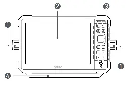
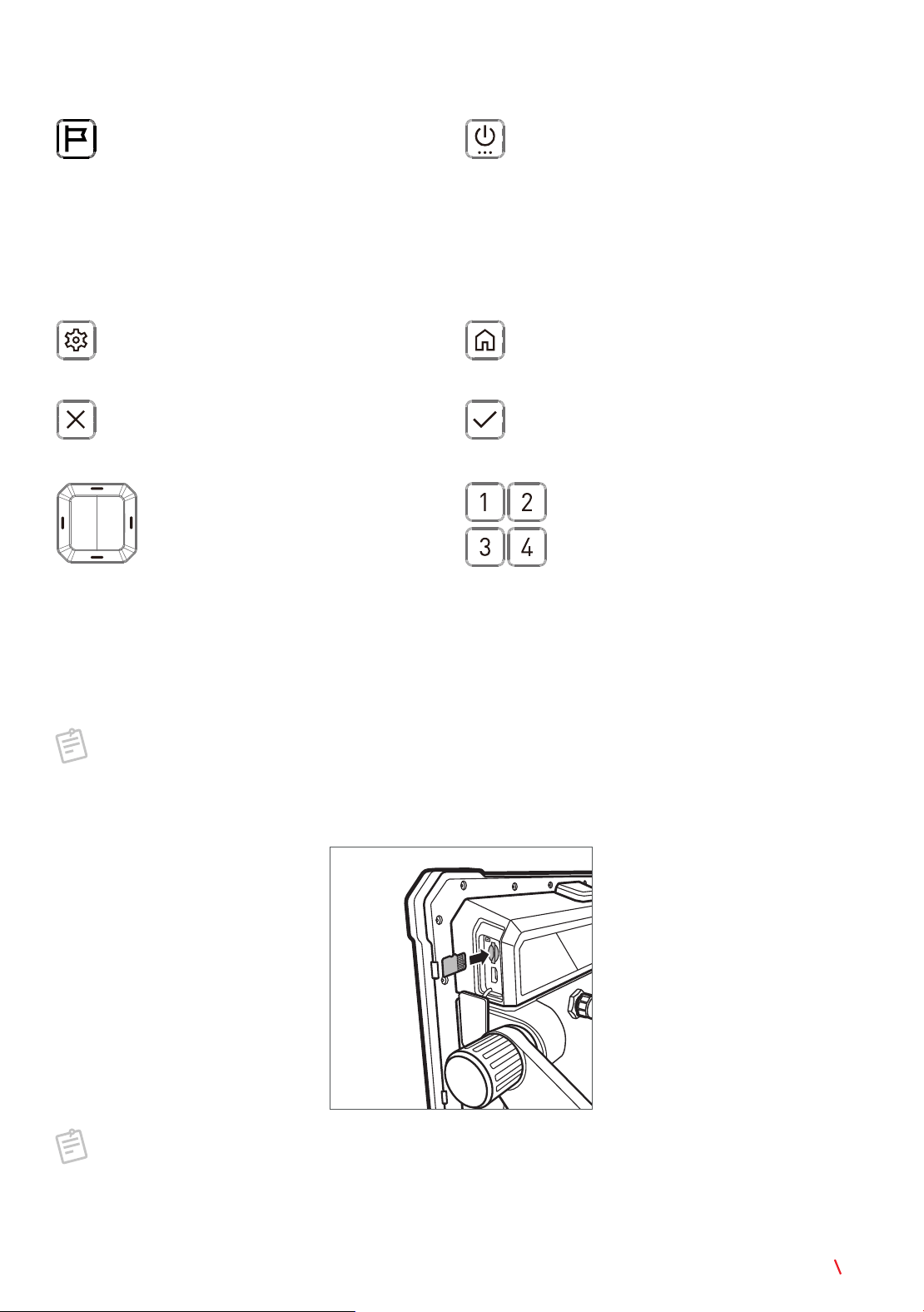
Control Keys
Waypoint
Press to add a waypoint at the current
location.
Power/Menu
• Press and hold to turn on or off the unit
(see page 7).
• Press to open or close the Quick Setup
menu (see page 9).
• When in standby mode, press to exit
standby and return to the previous
active state.
Settings
Press to open or close the Settings menu
from the side, if available.
Home
Press to return to the Home screen from
any operation.
Exit
Press to close the Settings menu or the
Unit Tools page.
Enter
Press to confirm selection.
Navigation
Press to move through menu items.
Shortcut
Assign a function to each of these
keys for use as a shortcut.
Insert a microSD Card
Use the microSD card to transfer data between units or to a computer, such as recording
tracks and screenshots. The microSD card must be formatted as FAT32 or exFAT.
NOTE
• Supported microSD card format: SD/SDHC/SDXC.
• The microSD card is not supplied with the product.
Fully insert the microSD card into the card slot until it clicks into place.
NOTE
To format the microSD card from the unit, on the Home screen, touch
SYSTEM
SETTINGS
>
SETUP
>
FORMAT SD CARD
. This action is irreversible. Consider
backing up the data to an external storage device first.
#02

6 Get Started
Mount the Head Unit
CAUTION
Mount the unit on a flat surface. Allow enough clearance to tilt the unit freely
while cables are connected.
Refer to the Installation Guide for detailed instructions.
Connect the Head Unit to Power
Power your unit using a 12-volt source by connecting it directly to a battery or tapping into
your boat’s electrical system.
NOTE
Connect the unit to the main starting battery when possible. Do not use a trolling
motor battery.
CAUTION
• Route the power cable away from sharp metal edges, or add protective covering
where needed.
• Install circuit protection (1 A fuse or circuit breaker) in the positive line near the
power source to protect the wiring.
To connect the unit to power:
WARNING
Do not turn on the power until the connection is securely made.
1. Route the power cable from the unit location to the power source.
2. Insert the power connector to the unit’s power jack.
3. Connect the red lead to the positive (+) power source terminal and the black lead to the
negative (-) terminal.
NOTE
Refer to your shuttle or boat manual for specific installation instructions.
#02
7
Use the Head Unit
3 Use the Head Unit
Turn On/Off the Head Unit
• Press and hold the
Power/Menu
key to turn on the unit. The unit enters the Home screen
after startup.
• Press and hold the
Power/Menu
key until the Power options appears on the screen, then
touch
Power off
to turn off the unit.
NOTE
If the unit does not respond to any operations, press and hold the
Power/Menu
key
until the unit is turned off forcefully.
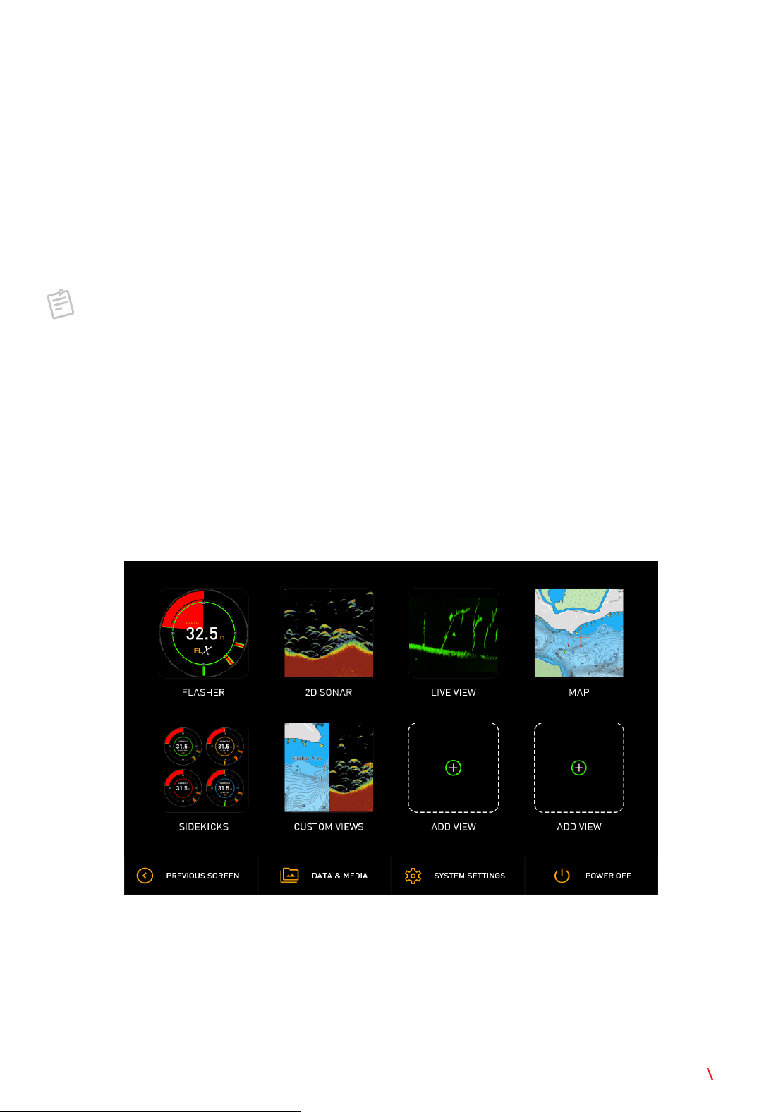
Identify the Main Screen Layout
Home Screen
The unit enters the Home screen after startup and can be accessed from any operation by
pressing the
Home
key. The Home screen consists of main applications and a toolbar at
the bottom.
#02

8 Use the Head Unit
Application
Touch a button to enter the application in full screen. To configure settings available
in the application, touch
to open the settings menu from the side. To exit from the
application, touch .
Item Description
FLASHER
A real-time circular display that shows depth, fish, and bottom
changes instantly.
2D SONAR
A traditional sonar view that displays fish arches, structure, and
bottom contour.
LIVE VIEW
A forward- and downward-facing sonar that shows fish and
movement in real time as it happens.
MAP
A GPS-based chart view that helps you navigate, mark waypoints,
and track your fishing spots.
SIDEKICKS
Connects and uses accessories like wireless transducers to expand
how and where you fish.
CUSTOM VIEWS
User-configurable screen layouts that let you combine and arrange
features to match your fishing style.
ADD VIEW
Creates extra custom views on the Home screen for quick access
to your favorite setups.
Toolbar
Touch a button to perform its function. To exit settings, touch .
Item Description
PREVIOUS SCREEN
Returns to the previous screen.
DATA & MEDIA
Manages all the images and videos.
SYSTEM SETTINGS
• Customizes the unit based on your preferences.
• Sets up basic tools such as language, time and time zone, and
Wi-Fi.
POWER OFF
Turns off the unit.
#02
9
Use the Head Unit
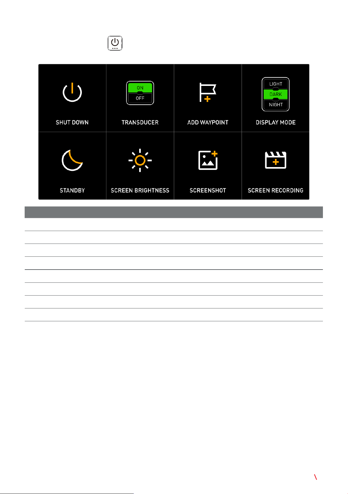
Quick Setup Menu
Press the
Power/Menu
key to open the Quick Setup menu. Touch an option to
perform its function.
Function Description
SHUT DOWN
Turns off the unit.
TRANSDUCER
Switches the transducer on or off.
ADD WAYPOINT
Adds a waypoint to the current location.
DISPLAY MODE
Selects a preferred theme for the unit display.
STANDBY
Switches the unit to standby mode.
SCREEN BRIGHTNESS
Adjusts the screen brightness.
SCREENSHOT
Takes a screenshot of the current screen.
SCREEN RECORDING
Records the current route.
Set the Language
To set the unit language you are using, on the Home screen, touch
SYSTEM SETTINGS
>
SETUP
, and select an option from the
LANGUAGE
drop-down menu.
Set the Time
The unit time is set to use the network as the time source by default. To set the unit time
manually, follow the steps below:
1. On the Home screen, touch
SYSTEM SETTINGS
>
SETUP
.
2.
CLOCK SETUP
: Touch
MANUAL
. Scroll to select the hours, minutes, and time notation,
then touch
SET TIME
to confirm selection.
3.
TIME ZONE
: Select an option from the drop-down menu to set the time zone you are in.
#02

10 Use the Head Unit
4.
DAYLIGHT SAVINGS
: Touch to switch the daylight saving time on or off.
Set Up the Wi-Fi Network
To use wireless accessories, configure the Wi-Fi settings.
1. On the Home screen, touch
SYSTEM SETTINGS
>
SETUP
>
Wi-Fi SETTINGS
.
2. Switch on Wi-Fi to display the list of available networks. Select an access point, enter
the password, and touch
CONNECT
.
3. Once connected successfully, “
Connected
” appears under the network name to indicate
the connection status.
Cast the Screen to a Remote Display
Mirror the unit screen to a network-enabled display remotely.
1. On the Home screen, touch
SYSTEM SETTINGS
>
SETUP
>
CAST DISPLAY
.
2. A list of available wireless display devices appears by default. Touch the device you want
to connect to.
3. On the display device, follow the onscreen instructions to grant permission for the
connection to and from the unit.
4. Once connected successfully, the device name on the unit screen displays “
Connected
”.
The content shown on the unit screen is automatically mirrored to the display device.
#02

11
Appendixes
4 Appendixes
Appendix A: Specifications
NOTE
Specifications are subject to change without notice.
Head Unit
Item Specification
Display
Dimension 10.1” Touchscreen
Resolution 1080 x 800
Viewing angles in degrees 80° top / bottom / left / right
Brightness 1000 nit (typ.)
Physical
Dimensions 311 mm x 193.3 mm x 78.9 mm
Weight 3.5 lbs / 1.7 kg
Mounting type Bracket mount
Keypad 13 physical keys
Electrical
Supply voltage 12 VDC (10–19 VDC)
Power consumption (max) 15.24 W (at 12 VDC)
Environmental
Operating temperature range -20°C to 55°C (4°F to 131°F)
Storage temperature -30°C to 70°C (-22°F to 158°F)
Waterproof rating IPX7 with card door closed
Interface/
connectivity
Sonar 1 port
Power 1 port
Card reader 1 MicroSD slot
Communication
interface
Positioning GPS
Wi-Fi Wi-Fi 5
Bluetooth Bluetooth 5.1
#02

12 Appendixes
Transducer
Item Specification
Operation frequency
425–1100 kHz
Operation temperature
0°C to 40°C (32°F to 104°F)
Waterproof rating
IPX7
Cable length
4.5 m
Cable pin number
12 pin
Beam width
36° x 20°
Dimensions
119.27 mm x 151.08 mm x 20.7 mm
Weight
<1.43 lb / 650 g
Appendix B: FCC Statement
Federal Communications Commission (FCC) Compliance
This device complies with part 15 of the FCC Rules. Operation is subject to the following
two conditions: (1) this device may not cause harmful interference, and (2) this device
must accept any interference received, including interference that may cause undesired
operation.
This equipment has been tested and found to comply with the limits for a Class B digital
device, pursuant to part 15 of the FCC rules. These limits are designed to provide
reasonable protection against harmful interference in a residential installation. This
equipment generates, uses, and can radiate radio frequency energy and may cause
harmful interference to radio communications if not installed and used in accordance
with the instructions. However, there is no guarantee that interference will not occur in
a particular installation. If this equipment does cause harmful interference to radio or
television reception, which can be determined by turning the equipment off and on, the
user is encouraged to try to correct the interference by one of the following measures:
• Reorient or relocate the receiving antenna.
• Increase the separation between the equipment and the receiver.
• Connect the equipment into an outlet on a circuit different from that to which the receiver
is connected.
• Consult the dealer or an experienced radio/TV technician for help.
CAUTION
Changes or modifications not expressly approved by the party responsible for
compliance could void the user’s authority to operate the equipment.
#02

13
Appendixes
Appendix C: ISED Statement
Innovation, Science and Economic Development Canada Compliance
This device contains licence-exempt transmitter(s)/receiver(s) that comply with Innovation,
Science and Economic Development Canada’s licence-exempt RSS(s). Operation is
subject to the following two conditions: (1) this device may not cause interference, and (2)
this device must accept any interference, including interference that may cause undesired
operation of the device.
L’émetteur/récepteur exempt de licence contenu dans le présent appareil est conforme
aux CNR d’Innovation, Sciences et Développement économique Canada applicables
aux appareils radio exempts de licence. L’exploitation est autorisée aux deux conditions
suivantes : (1) l’appareil ne doit pas produire de brouillage ; (2) l’appareil doit accepter tout
brouillage radioélectrique subi, même si le brouillage est susceptible d’en compromettre le
fonctionnement.
Specific Restrictions for 5 GHz Band (Canada)
The device for operation in the band 5150–5250 MHz is only for indoor use to reduce the
potential for harmful interference to co-channel mobile satellite systems.
Les dispositifs fonctionnant dans la bande de 5 150 à 5 250 MHz sont réservés uniquement
pour une utilisation à l’intérieur afin de réduire les risques de brouillage préjudiciable aux
systèmes de satellites mobiles utilisant les mêmes canaux.
GNSS / GPS Receiver Notice
The navigation device may experience degraded performance if it is used in proximity to
any device that uses a terrestrial broadband network operating close to the frequencies
used by any Global Navigation Satellite System (GNSS), such as the Global Positioning
Service (GPS). Use of such devices may impair reception of GNSS signals.
Radio Frequency Radiation Exposure
This device is a mobile transmitter and receiver that uses an internal antenna to send and
receive low levels of radio frequency (RF) energy for data communications. The device
emits RF energy below the published limits when operating in its maximum output power
mode and when used with authorized accessories. To comply with FCC and ISED RF
exposure compliance requirements, this equipment should be installed and operated with a
minimum distance of 20 cm (7.87 in.) between the radiator and your body. This transmitter
must not be co-located or operating in conjunction with any other antenna or transmitter.
Cet équipement est conforme aux limites d’exposition aux rayonnements de la FCC et
d’ISDE établies pour un environnement non contrôlé. Cet équipement doit être installé et
utilisé avec un minimum de 20 cm de distance entre la source de rayonnement et votre
corps. Cet émetteur ne doit pas être co-localisé ou fonctionner en conjonction avec une
autre antenne ou un autre émetteur.
#02

Regulatory 01, 2026/03/03
© 2026 Vexilar, Inc. All rights reserved.
#02