User Manual
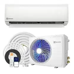
ELECTROLUX VEGA SERIES MINI SPLIT AIR CONDITIONER
Models: SAC09SNV19-1 | SAC12SNV19-1 | SAC18SHV19-1 | SAC24SHV19-1

CONTENTS
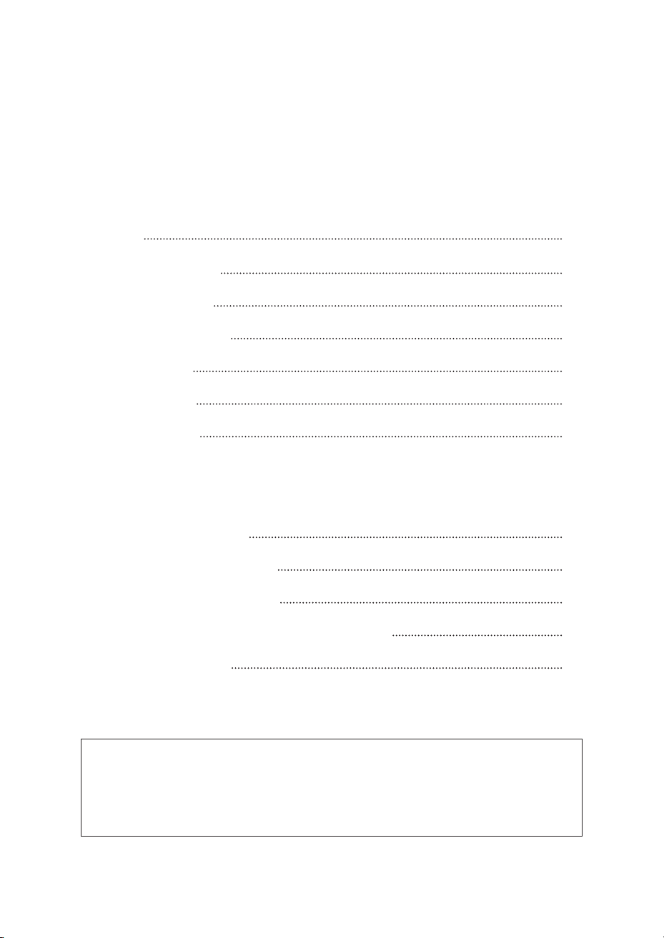
Warning
02
Installation for indoor unit
30
Clean and care
18
Remote control
11
Notices for usage
08
Check after installation and test operation
38
Safety Precautions
05
Installation for outdoor unit
33
Troubleshooting
20
Names of each part
10
Maintenance Notice
39
Notices for installation
23
01
OPERATION AND MAINTENANCE
INSTALLATION SERVICE
All the illustrations in this manual are for explanatory purpose only. Your air
conditioner may be slightly different. The actual shape prevails. They are
subject to change without notice for future improvement.
NOTE
WARNING
02
FCC WARNING
FCC STATEMENT
IC STATEMENT
NOTE: FCC and IC related content only applies to models with WiFi function.
WARNING: Changes or modifications to this unit not expressly approved by the
party responsible for compliance could void the user’s authority to operate the
equipment.
This device complies with Part 15 of the FCC Rules. Operation is subject to the
following two conditions:
This device complies with Industry Canada licence-exempt RSS standard(s).
Operation is subject to the following two conditions: (1) this device may not
cause interference, and (2) this device must accept any interference, including
interference that may cause undesired operation of the device.
Le présent appareil est conforme aux CNR d’Industrie Canada applicables aux
appareils radio exempts de licence. L’exploitation est autorisée aux deux con-
ditions suivantes : (1) l’appareil ne doit pas produire de brouillage, et (2) l’utilisa-
teur de l’appareil doit accepter tout brouillage radioélectrique subi, même si le
brouillage est susceptible d’en compromettre le fonctionnement.
(1) this device may not cause harmful interference, and (2) this device must
accept any interference received, including interference that may cause
undesired operation.
However, there is no guarantee that interference will not occur in a particular
installation. If this equipment does cause harmful interference to radio or televi-
sion reception, which can be determined by turning the equipment off and on,
the user is encouraged to try to correct the interference by one or more of the
following measures:
Note: This equipment has been tested and found to comply with the limits for
a Class B digital device, pursuant to part 15 of the FCC Rules. These limits are
designed to provide reasonable protection against harmful interference in a
residential installation. This equipment generates, uses and can radiate radio
frequency energy and, if not installed and used in accordance with the
instructions, may cause harmful interference to radio communications.
Reorient or relocate the receiving antenna.
Connect the equipment into an outlet on a circuit different from that to which
the receiver is connected.
Increase the separation between the equipment and receiver.
Consult the dealer or an experienced radio/TV technician for help.
WARNING
03
IC STATEMENT
This equipment complies with FCC’s and IC’s RF radiation exposure limits set forth
for an uncontrolled environment. The antenna(s) used for this transmitter must be
installed and operated to provide a separation distance of at least 20cm from all
persons and must not be collocated or operating in conjunction with any other
antenna or transmitter. Installers must ensure that 20cm separation distance will
be maintained between the device (excluding its handset) and users.
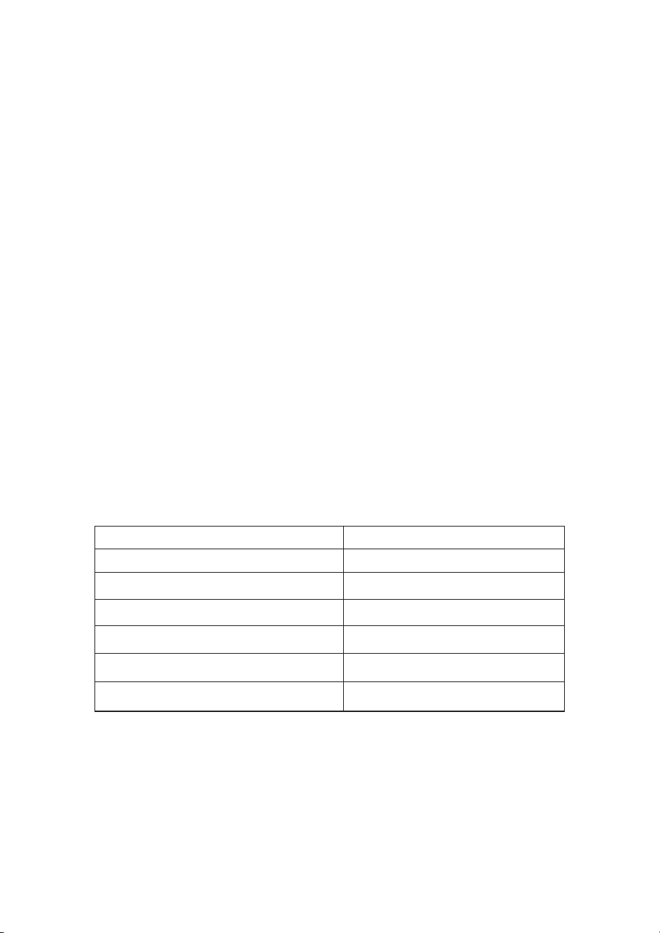
The minimum room size required depends on the amount of refrigerant in your
system:
Cet appareil est conforme aux limites d’exposition au rayonnement RF stipulées
par la FCC et l’IC pour une utilisation dans un environnement non contrôlé. Les
antennes utilisées pour cet émetteur doivent être installées et doivent fonctionner
à au moins 20 cm de distance des utilisateurs et ne doivent pas être placées près
d’autres antennes ou émetteurs ou fonctionner avec ceux-ci. Les installateurs
doivent s’assurer qu’une distance de 20 cm sépare l’appareil (à l’exception du
combiné) des utilisateurs.
WARNING: This air conditioner uses R32 flammable refrigerant.
Room Size Requirements
Note: If R32 air conditioners are improperly handled, they may cause serious
injury or property damage.
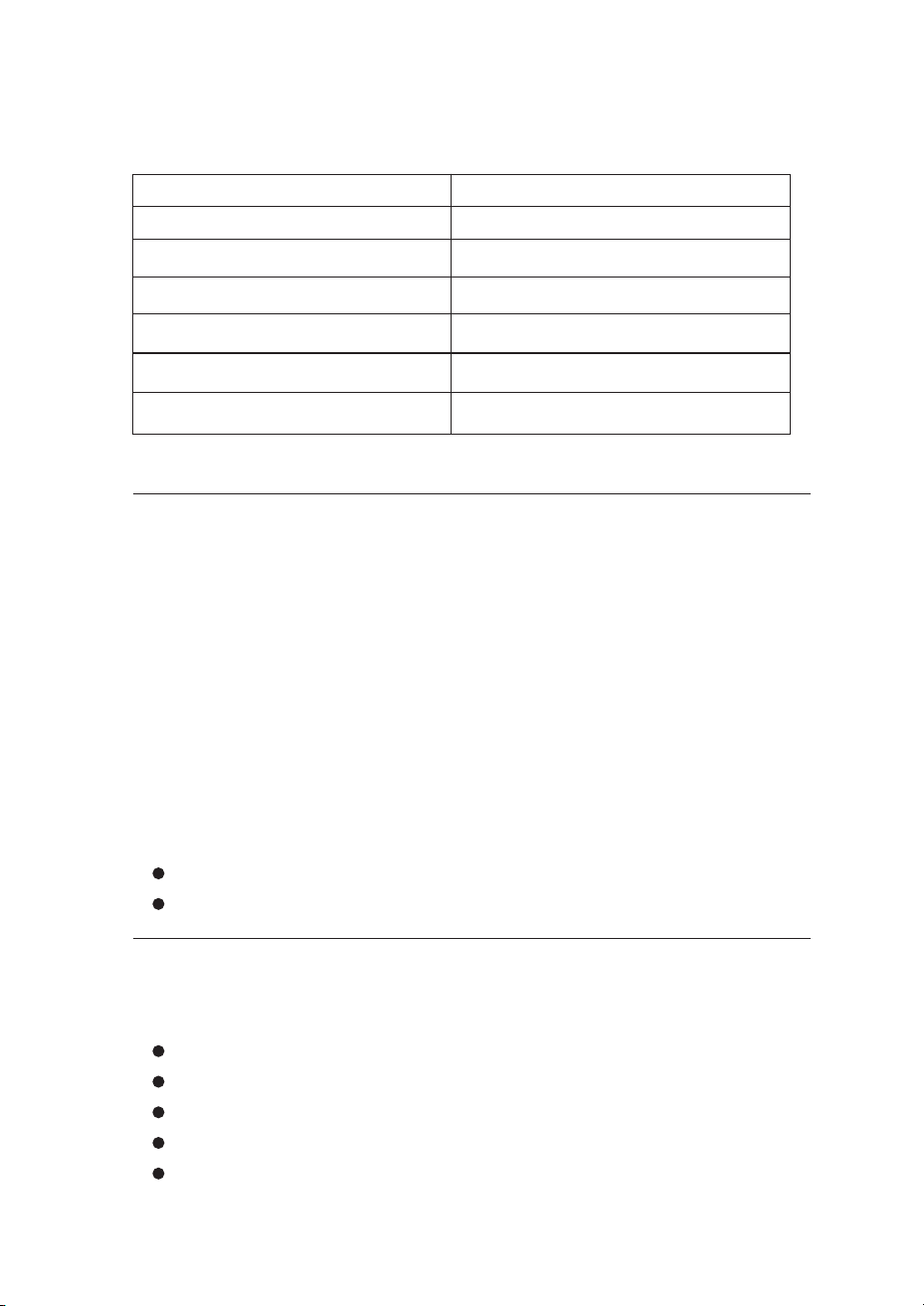
Refrigerant Charge Amount (kg) Minimum Room Size (m²)
Less than 1.84
1.84 to 2.34
2.341 to 2.84
2.841 to 3.34
3.341 to 3.84
3.841 to 4.34
7
9
10.5
12.5
14
18
WARNING
04
Important Safety Requirements:
Only use defrosting and cleaning methods recommended by the manufacturer.
Be aware that the refrigerant may be odorless.
The unit must be installed with a stop valve cover.
Read all instructions carefully before installing, using, or servicing this unit.
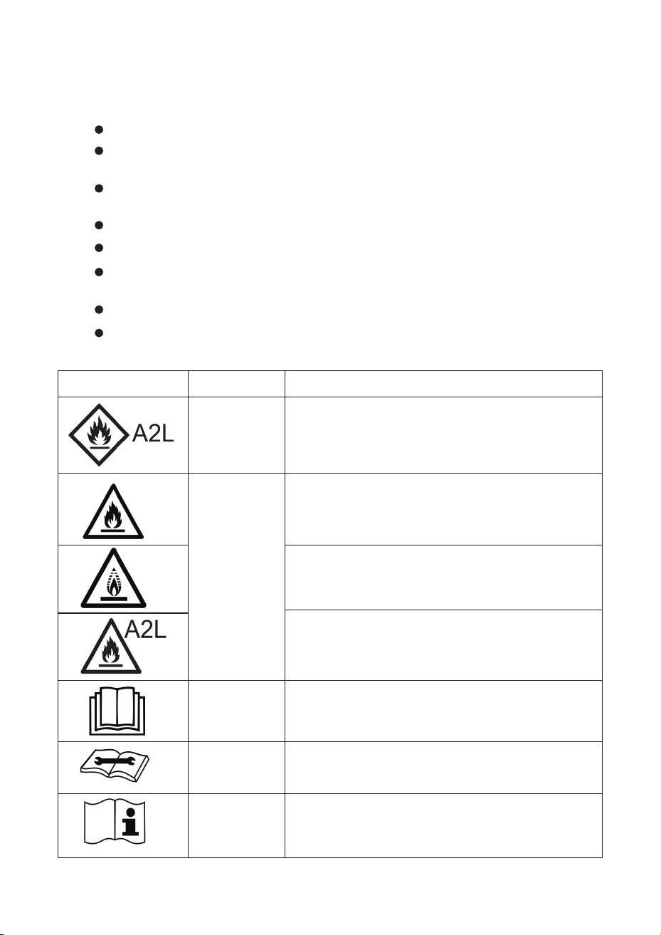
This appliance uses a flammable refrigerant. If
refrigerant leaks near an ignition source, fire may
occur. (Only for the AC with UL or ETL-MARKING,
UL60335-2-40).
This appliance uses a flammable refrigerant. If
refrigerant leaks near an ignition source, fire may
occur. (For the AC with CE-MARKING &
CB-MARKING, IEC 60335-2-40+A1:2016)
This appliance uses a low burning velocity
material. (Only for the AC with CB-MARKING,
IEC60335-2-40:2018)
Read the operating manual carefully before use.
This equipment should be installed and serviced by
qualified service personnel following the installation
manual.
Additional information is available in the operating
manual or installation manual.
This appliance uses a low burning velocity material.
(For the AC with CB-MARKING & CE-MARKING, IEC
60335-2-40:2022 & EN IEC 60335-2-40:2024 and the
latest version)
Store the unit where it cannot be accidentally damaged.
Never pierce or burn the air conditioner. Check that the refrigerant pipes are
not damaged.
Store the unit in a room away from open flames, operating gas appliances,
or electric heaters.
Service and repairs must be performed by qualified technicians after proper
safety checks.
SYMBOL NOTE
WARNING
WARNING
CAUTION
CAUTION
CAUTION
EXPLANATION

05
SAFETY PRECAUTIONS
Improper installation or use can result in injury or property damage. Pay attention to
these safety levels:
WARNING: Risk of death or serious injury.
CAUTION: Risk of minor injury or property damage.
WARNING
This appliance can be used by children 8 years and older, and by people with
reduced physical, sensory, or mental abilities if they are supervised and under-
stand the risks involved. Children must not play with the appliance. Cleaning and
maintenance should not be done by children without supervision.
This appliance is not intended for use by people (including children) with
reduced physical, sensory, or mental abilities unless they are supervised by
someone responsible for their safety. Watch children to make sure they don’t play
with the unit. .
For units with CE marking:
For units without CE marking:
Electrical Safety
1. Ground the unit properly. Poor grounding can cause electric shock. Never
connect the ground wire to a gas pipe, water pipe, lightning rod, or telephone line.
10. Keep away from flammable materials. Maintain at least 1 m (3.3 ft) distance
from any flammable gas or liquid, or fire/explosion may occur.
2. Damaged power cords must be replaced by the manufacturer, a service agent,
or a qualified technician.
5. Don’t touch the power switch with wet hands or while the unit is running. This can
cause electric shock.
6. Don’t plug other appliances into the same outlet. This can cause electric shock,
fire, or explosion.
11. Don’t use harsh cleaners or spray water on the unit. This can cause electric
shock or damage.
12. Never try to repair it yourself. Improper repairs can cause fire or explosion. Call
a qualified service technician.
7. Always turn off and unplug before cleaning or maintenance to avoid electric shock.
3. Never pull on the power cord. Pulling or damaging it can cause severe electric
shock.
4. Turn off and unplug the unit when not in use for extended periods.
8. Keep the remote and indoor unit dry. Water can cause short circuits.
9. Ducts connected to this unit must not contain any ignition sources.
13. Don’t use during thunderstorms. Unplug the unit to prevent damage.
14. Keep hands and objects away from air vents. You could be injured or damage
the unit.
15. Make sure the mounting bracket is secure. If damaged, the unit could fall and
cause injury.
16. Don’t block air vents. Blocking airflow reduces performance and may shut down
the system.
17. Don’t point airflow at heaters or fireplaces. This can cause incomplete combus
tion and carbon monoxide poisoning.
18. Install a ground fault circuit breaker (GFCI) to prevent electric shock.
19. Installation must follow national electrical codes.
SAFETY PRECAUTIONS
06
This product contains fluorinated greenhouse gases. Refrigerant leakage contrib-
utes to climate change. Refrigerant with lower global warming potential (GWP)
would contribute less to global warming than a refrigerant with higher GWP, if
leaked to the atmosphere. This appliance contains a refrigerant fluid with a GWP
equal to . This means that if 1 kg of this refrigerant fluid would be leaked to the at-
mosphere, the impact on global warming would be times higher than 1 kg of CO2,
over a period of 100 years. Never try to interfere with the refrigerant circuit yourself
or disassemble the product yourself and always ask a professional.
Refrigerant and Environmental Information
Installation Location
DO NOT install the indoor unit above:
Additional Requirements:
Microwaves, ovens, or other heat sources
Pipe connections between indoor and outdoor units cannot be reused unless the
pipe is re-flared .
Fuse specifications are printed on the circuit board (example: 3.15A/250V AC)
Computers or devices that generate static electricity
Electrical outlets that are frequently used
SAFETY PRECAUTIONS
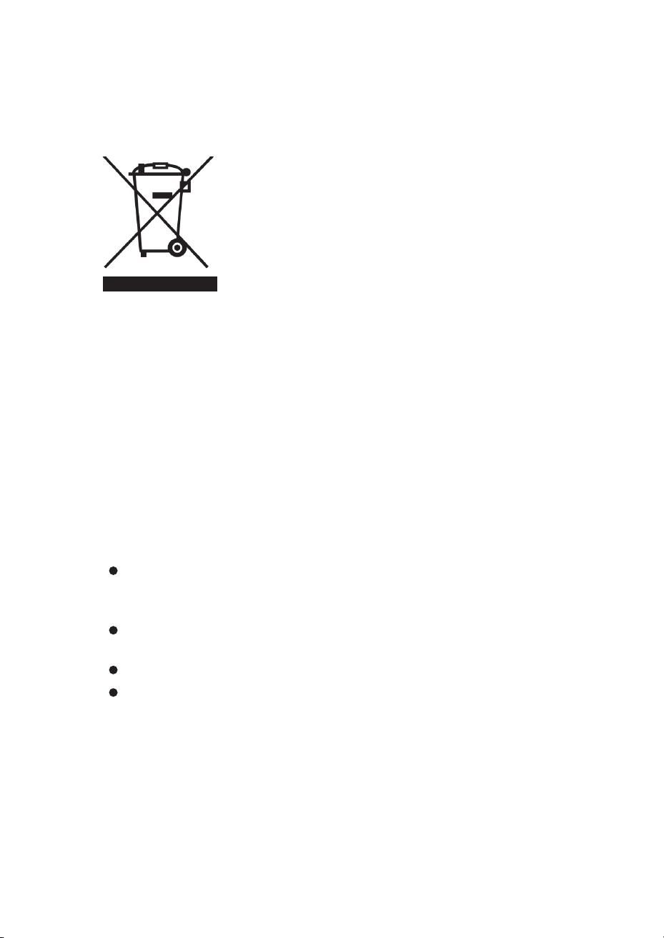
WEEE Disposal Information
Don’t throw this appliance in the regular trash. Use
designated electronics recycling facilities. Contact your
local government to find recycling locations near you.
If thrown in landfills, hazardous materials can leak into
groundwater and the food chain, harming your health.
When buying a new unit, retailers are required by law to
take back your old one for free disposal.
What the crossed-out trash bin symbol means:
07
CAUTION
1. Keep doors and windows closed while the unit is running, or cooling/heating
performance will suffer.
2. Don’t stand on or place heavy items on the outdoor unit. You could be injured
or damage the equipment.
5. Set a comfortable temperature. Don’t make the indoor temperature too different
from outdoors, as this wastes electricity.
6. Electrical requirements:
3. Use only for cooling and heating. Don’t use to dry clothes, preserve food, or for
other purposes.
4. Don’t aim cold air directly at your body for long periods. This can negatively
affect your health.
If your unit doesn’t have a power cord and plug, an all-pole disconnect switch
must be installed in the fixed wiring with contact separation of at least 3.0 mm
(0.12 in).
If permanently wired, install a residual current device (RCD) rated no more
than 30 mA.
The circuit breaker capacity must be at least 1.5 times the unit’s maximum current.
See the installation section of this manual for complete details.
NOTICES FOR USAGE
08
Temperature Limits
Your air conditioner may not work properly outside these temperature ranges:
Mode Location Temperature Limit
Above 43°C (109°F) - T1 units
Above 24°C (75°F)
Below -7°C (19°F)
Above 52°C (126°F) - T3 units
Below 18°C (64°F)
Above 27°C (81°F)
Cooling
Heating
Outdoor
Outdoor
Indoor
Indoor
What this means:
What this means:
When Turning Off
When outdoor temperature is too high, the unit may shut down automatically
to protect itself .
The fan won’t start right away when you turn on heat. This prevents cold air
from blowing out..
When you turn off the unit, it may keep running for a few seconds at low speed
before stopping completely. This is normal.
When outdoor temperature is too low, frost may form inside, causing water
dripping or other problems .
Frost may form outside when it’s cold and wet. The unit will automatically
defrost itself.
During extended cooling with high humidity (above 80%) and doors/windows
open, water may drip from the unit .
During defrost, heating stops for 5-12 minutes.
T1 and T3 refer to ISO 5151 climate ratings.
You may see steam coming from the outdoor unit during defrost. This is normal.
Heating resumes automatically when defrost finishes.
NOTICES FOR USAGE
09
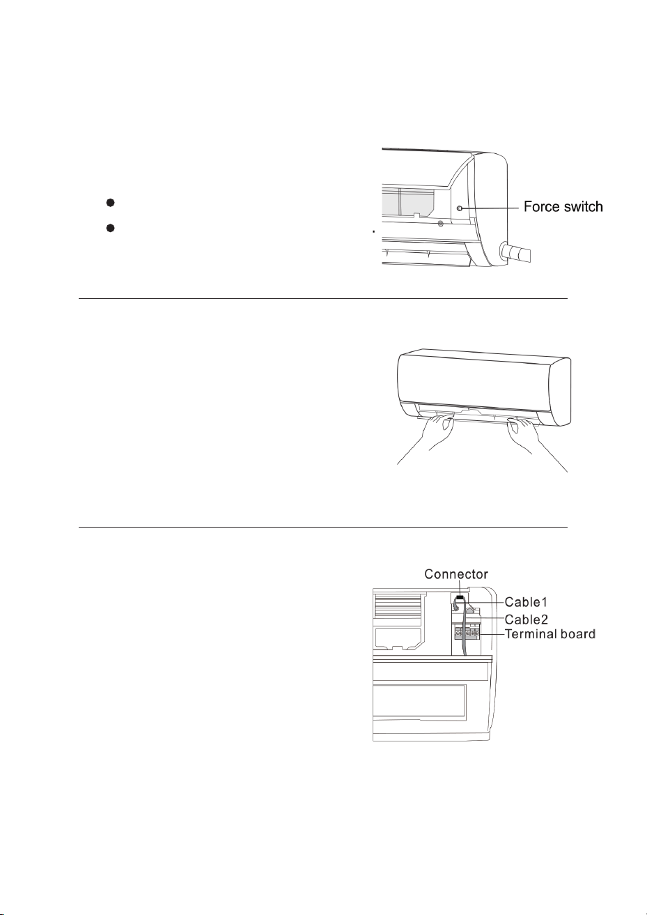
If You Lose the Remote Control
Adjusting Airflow Direction
Connector Positioning (For Installers)
Use the force switch button on the indoor unit:
Press when unit is OFF: starts in Auto mode
Press when unit is ON: turns off
1. Use the remote control buttons to adjust
up-down and left-right airflow. See your remote
manual for details.
1. Open the front panel of the indoor unit.
2. For models without motorized left-right
swing: manually move the air vents by hand.
2. Make sure the connector does not touch the
terminal board and is positioned correctly
as shown in the diagram.
WARNING: Adjust vents before turning on the unit, or you could pinch your
fingers. Never put your hands near the vents while the unit is running.
Diagram showing Cable 1, Cable 2, and Terminal Board
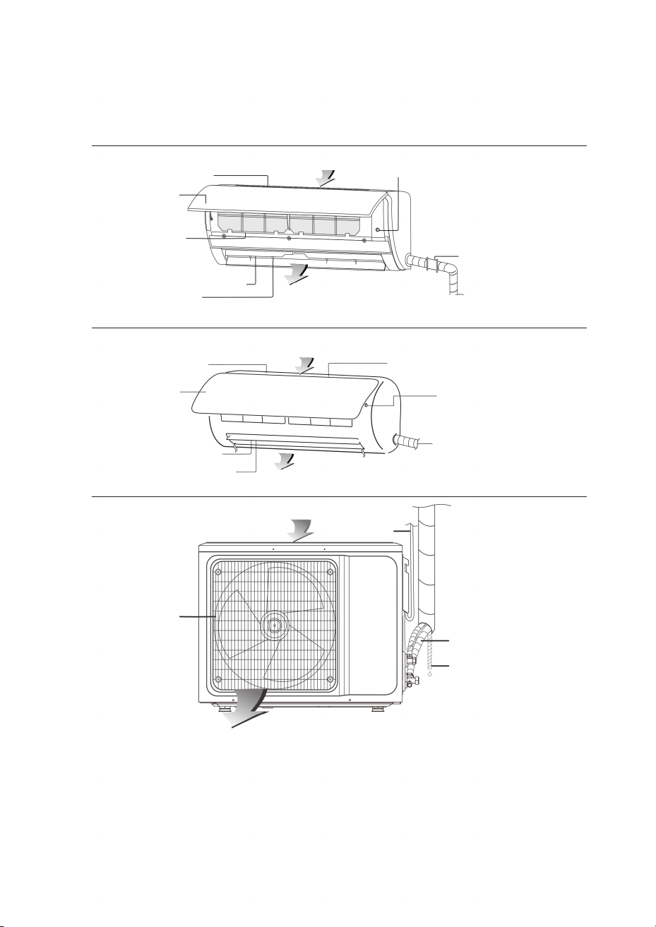
NAMES OF EACH PART
10
Indoor Unit
Outdoor Unit
( Fig B )
( Fig A )
Your indoor unit may look like Fig A or Fig B. Your actual unit may vary slightly.
Air outlet
Air outlet
Air outlet grille
Air outlet grille
Pipe protection ring
Pipe protection ring
Connecting Pipe
Drain hose
Manual on/off switch (force switch)
Manual on/off switch
(force switch)
Air inlet
Air inlet
Air inlet
Air inlet grille
Air inlet grille
Front panel
Front panel
Air filter
Air filter
Power Cable
Air louver (directional blades)
Air louver (directional blades)
Air vent
Air vent
Note: Pictures in this manual are for reference only. Your unit may look slightly
different. Features and appearance may change without notice.
Optional features (may not be on your model): Power plug, WiFi, negative ion
generator, vertical/horizontal auto swing.
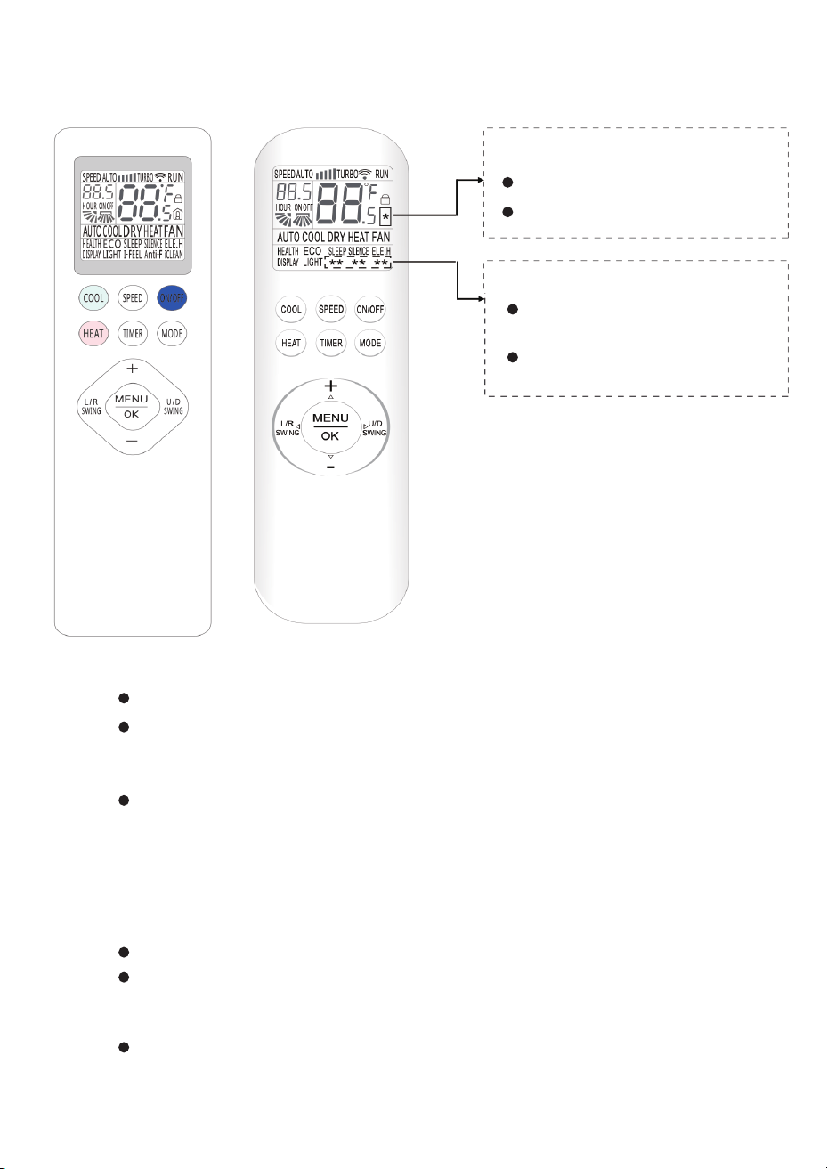
REMOTE CONTROL
11
Display Types:
Display Text Variations:
NOTE:
Type: A shown as %
Type: A shown as:
Type: B shown as:
COSY HUMI CLEAN
FEEL ANTI CLEAN
Type: B shown as ℃
1. There are two different display types
of remote control (Type A and Type
B). Your remote will be one of these
types.
2. The remote controller display shows
all symbols when powered on;
other times it only displays symbols
corresponding to the current
operation.
1. ON/OFF Button
2. MODE Button
3. TIMER Button
Press this button to turn the unit on or off.
Press this button to select the operation mode as follows:
With the unit on, press this button to set an off timer or turn off an existing on timer.
Press the button again to confirm the setting, and “ON (OFF)” will stop flashing.
Press this button once, and “ON(OFF)” will flash. Press “+” or “−” to set the number
of hours when the unit will be turned on/off, with an interval of 0.5 hour and a
range of 0.5-24 hours.
This will clear any existing timer and sleep settings.
→ AUTO → COOL → DRY → HEAT → FAN
NOTE: Heat mode is not available for cool-only units. Please read the Usage
for Mode section for a detailed description.
REMOTE CONTROL
12
If the “TIMER” button is not pressed within 10 seconds after “ON (OFF)” starts
flashing, the timer setting will be canceled.
If a timer setting is confirmed, press this button again to cancel it.
4. HEAT Button
5. COOL Button
6. SPEED Button
7. + & − Button
9. L/R SWING Button
8. MENU & OK Button
Press this button to enter “HEAT” mode.
Press this button to enter “COOL” mode.
The temperature setting range: 16°C (60°F) ~ 32°C (90°F).
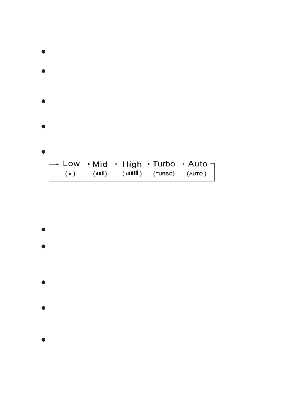
Press this button to select fan speed as follows:
Each time “+” is pressed, the temperature setting will increase by 1°C (1°F), and
each time “−” is pressed, it will decrease by 1°C (1°F).
Press this button to activate left/right swing, and press it again to turn off the
swing function.
Press the “MENU” button to enter the function selection mode. Then press △ (+),
▽(−), ◁ (L/R SWING), and ▷ (U/D SWING) to choose the function you want. After
selecting a function, press the “OK” button to activate it.
In function selection mode, press △ (+), ▽(−), ◁ (L/R SWING), and ▷ (U/D SWING).
The selected character in the LCD will flash if the function is available.
NOTE: Auto air speed is not available in fan mode.
Turbo air speed is not available in auto mode.
This button is invalid in dry mode.
NOTE: The temperature cannot be set in auto or fan mode.
10. U/D SWING Button
11. HEALTH
13. SLEEP
12. ECO
Press this button to activate up/down swing, and press it again to turn off the
swing function.
To activate the HEALTH function:
To activate SLEEP mode:
To activate ECO mode:
About ECO mode:
REMOTE CONTROL
13
NOTE:
To enable “Rated Swinging” mode: With the unit on, press and hold the “U/D
SWING” button for 3 seconds. The button will switch to “Rated Swinging” mode,
allowing you to select specific swing positions.
To exit “Rated Swinging” mode: Press and hold the “U/D SWING” button for 3
seconds, or remove and reinstall the remote control batteries. The power on/off
button cannot be used to exit this mode.
In cooling mode, variable-speed air conditioners will automatically enter ECO
mode, which uses minimal electricity. ECO mode automatically exits after 8 hours.
The unit will automatically exit SLEEP mode after 10 hours of continuous
operation and return to the previous settings.
ECO mode is not available on fixed-speed air conditioners.
Changing modes or turning off the remote will cancel ECO mode.
1. With the unit on, press “MENU”
1. With the unit on, press “MENU”
1. In cooling mode, press “MENU”
2. Use the △(+), ▽(−), ◁, and ▷ buttons to select “HEALTH”
2. Use the △(+), ▽(−), ◁, and ▷ buttons to select “SLEEP”
2. Use the △(+), ▽(−), ◁, and ▷ buttons to select “ECO”
3. When “HEALTH” flashes on the display, press “OK” to turn the function on or off.
3. When “SLEEP” flashes on the display, press “OK” to turn the function on or off.
3. When “ECO” flashes on the display, press “OK” to turn the function on or off .
NOTE: Electricity consumption depends on ambient temperature and room
characteristics. When the temperature is high or the room is large,
use ECO mode with caution.
NOTE: The sleep function cannot be activated in fan or auto mode.
In sleep mode, the air conditioner display screen turns off.
REMOTE CONTROL
14
14. SILENCE
15. ELE.H
16. DISPLAY
18. COSY (Only Type A)
17. LIGHT
To activate the SILENCE (quiet) mode:
To activate auxiliary electric heating:
To control the screen display:
To activate COSY (comfort) mode:
To activate LIGHT (light sensing) mode:
Automatic brightness adjustment:
When COSY mode is active:
1. With the unit on, press “MENU”
1. With the unit on, press “MENU”
1. With the unit on, press “MENU”
1. In cooling mode with the unit on, press “MENU”
1. With the unit on, press “MENU”
2. Use the △(+), ▽(−), ◁, and ▷ buttons to select “SILENCE”
2. Use the △(+), ▽(−), ◁, and ▷ buttons to select “ELE.H”
2. Use the △(+), ▽(−), ◁, and ▷ buttons to select “DISPLAY”
2. Use the △(+), ▽(−), ◁, and ▷ buttons to select “COSY”
2. Use the △(+), ▽(−), ◁, and ▷ buttons to select “LIGHT”
3. When “SILENCE” flashes on the display, press “OK” to turn the function on or off.
3. When “ ELE.H” flashes on the display, press “OK” to turn auxiliary heating on or off .
3. When “DISPLAY” flashes on the display, press “OK” to turn the screen on or off
3. When “COSY” flashes on the display, press “OK” to turn comfort mode on or off
3. When “LIGHT” flashes on the display, press “OK” to light sensing on or off
The unit will automatically activate auxiliary heating based on the ambient
temperature to accelerate heating.
This button is disabled on some models.
Fan speed is automatically set to auto and swing function is canceled.
COSY mode will automatically turn off if you turn off the unit, change the mode, adjust
SLEEP, change fan speed, or activate swing. The unit will then return to the previous
settings
The unit will automatically adjust the display brightness based on the indoor ambient
light level.

REMOTE CONTROL
15
19. HUMI (Only Type A)
To activate HUMI (humidifying) mode:
To manually activate iCLEAN:
To activate Anti-F manually:
1. Press “MENU”
1. With the unit off, press “MENU”
1. With the unit off, press “MENU”
2. Use the △(+), ▽(−), ◁, and ▷ buttons to select “HUMI”
2. Use the △(+), ▽(−), ◁, and ▷ buttons to select “iCLEAN”
2. Use the △(+), ▽(−), ◁, and ▷ buttons to select “Anti-F”
3. When “HUMI” flashes on the display, press “OK” to turn humidifying mode on or off.
3. When “iCLEAN” flashes on the display, press “OK” to start or stop the cleaning cycle.
3. When “ Anti-F” flashes on the display, press “OK” to turn the function on or off.
NOTE: The humidifying function is not available in dry mode.
NOTE: The cleaning function will automatically stop within one hour.
NOTE: When child-lock is active, the remote control will display a lock icon “
🔒
”
20. iCLEAN
21. Child-lock
22. Anti-F (Only Type B)
Automatic self-cleaning:
To activate child-lock:
The unit will automatically clean dust from the evaporator and dry or blow-dry
moisture.
Press and hold the “HEAT” and “MODE” buttons at the same time for at least
3 seconds.
Anti-F function: When the unit shuts down after operating in cooling, dry, or auto
(cooling) mode, it will continue running for about 3 minutes to dry moisture from the
evaporator. This prevents bacteria buildup on the evaporator, which causes mold
and unpleasant odors that are harmful to health.
REMOTE CONTROL
16
23. I-FEEL (Only Type B)
25. 8°C Heating Function
26. Temperature Setting Function:
24. °C/°F
To activate I-FEEL (remote sensor) mode:
To activate 8°C heating:
When 8°C heating mode is active:
8°C heating function is only available for YKR-T/111E and YKR-T/121E remote control.
Only T121E has this function:
1. With the unit on, press “MENU”
1. Only T121E remote controls have this feature.
3. To switch between min/max settings: When setting the minimum temperature,
long press “Cool” and “Mode” for 10 seconds or more to switch to the maximum
temperature setting.
4. You must reset this function after replacing the battery.
2. To set maximum temperature: In shutdown state, press and hold “Cool” and
“Mode” at the same time for 10 seconds or more. The display will show the maxi
mum temperature (32°C/90°F), and “H” will flash. Press [+/-] to adjust the range,
then press “Mode” to confirm. The minimum temperature setting (16°C/60°F) will
display, and “L” will flash. Press [+/-] to adjust the minimum range. Press “Mode” to
confirm, and the setting is complete.
2. Use the △(+), ▽(−), ◁, and ▷ buttons to select “I-FEEL”
3. When “I-FEEL” flashes on the display, press “OK” to turn the function on or off.
The temperature is displayed in Celsius by default.
a. Pressing “HEAT,” switching to another mode, or selecting sleep function will exit
8°C heating .
b. The “SPEED,” “+”, “−” buttons become inactive.
c. Fahrenheit/Celsius switching function becomes inactive.
d. Turning the unit off and back on will retain the 8°C heating function.
e. In the “MENU” menu, ELE.H function cannot be selected.
Press and hold the “COOL” and “HEAT” buttons at the same time for 3 seconds or
more to switch between °C or °F.
Only in heating mode while the unit is on, press and hold the “MODE” and “+”
buttons at the same time for 3 seconds or more
NOTE: Temperature display in Fahrenheit is not available for some models.
When temperature is displayed in Fahrenheit on the remote controller,
it might be in Celsius on the unit, the function and operation of which
will not be affected.
REMOTE CONTROL
17
Usage for Mode
★ Auto Operation Mode
★ Fan Operation Mode
★ Dry Operation Mode
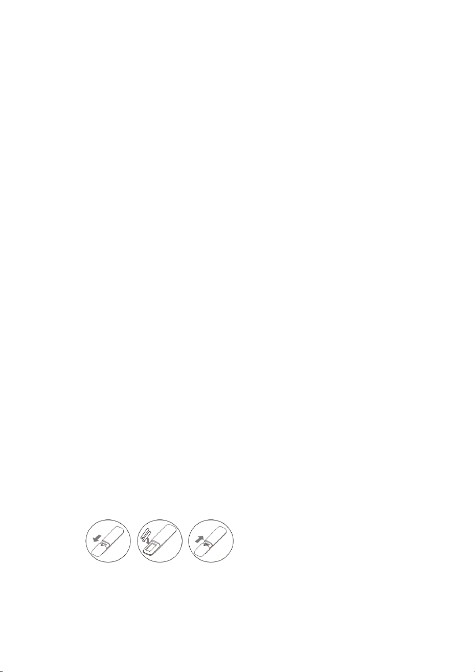
★ Fix Batteries
★ Cool/Heat Operation Mode
1. Press “ON/OFF” to start the air conditioner.
1. Press “ON/OFF” to start the air conditioner.
1. Press “ON/OFF” to start the air conditioner.
1. Slide to open the battery cover in the direction indicated by the arrow.
1. Press “ON/OFF” to start the air conditioner.
2. Press “MODE” to select auto operation mode.
2. Press “MODE” to select fan operation mode.
2. Press “MODE” to select dry operation mode.
2. Insert two brand new batteries (7#), and position the batteries correctly according
to the polarity markings (+ & −).
2. Press “MODE” to select cool or heat operation mode.
3. Press “SPEED” to select fan speed from Low, Mid, High, Auto.
3. Press “SPEED” to select fan speed from Low, Mid, High.
3. Press “+” or “−” to set the temperature from 16°C (60°F) to 32°C (90°F). The display
changes as you press the button. .
3. Replace the battery cover.
3. Press “+” or “−” to set the temperature from 16°C (60°F) to 32°C (90°F). The display
changes as you press the button.
4. Press “ON/OFF” again to stop the air conditioner.
4. Press “ON/OFF” again to stop the air conditioner.
4. Press “ON/OFF” again to stop the air conditioner.
4. Press “SPEED” to select fan speed from Low, Mid, High, Turbo, Auto.
5. Press “ON/OFF” again to stop the air conditioner.
NOTE: In auto mode, the temperature settings is non-effective.
NOTE: In fan mode, the temperature settings is non-effective.
NOTE: In dry mode, the speed settings is non-effective.
NOTE: The cold wind type has no heating function.
CLEAN AND CARE
18
Use only a soft dry cloth or a cloth slightly moistened with a mild, neutral
detergent to clean the housing. Do not use thinner, gasoline, or other harsh
solvents, as they may damage the surface.
Clean the air filter regularly to prevent dust buildup, which can reduce
performance. If the environment is especially dusty, clean the filter more often.
After removing the filter, do not touch the aluminum fins of the indoor unit with
your fingers or bend the refrigerant pipes.
WARNING
Turn off the air conditioner and disconnect power for at least 5 minutes before
cleaning. There is a risk of electric shock if you clean it while powered.
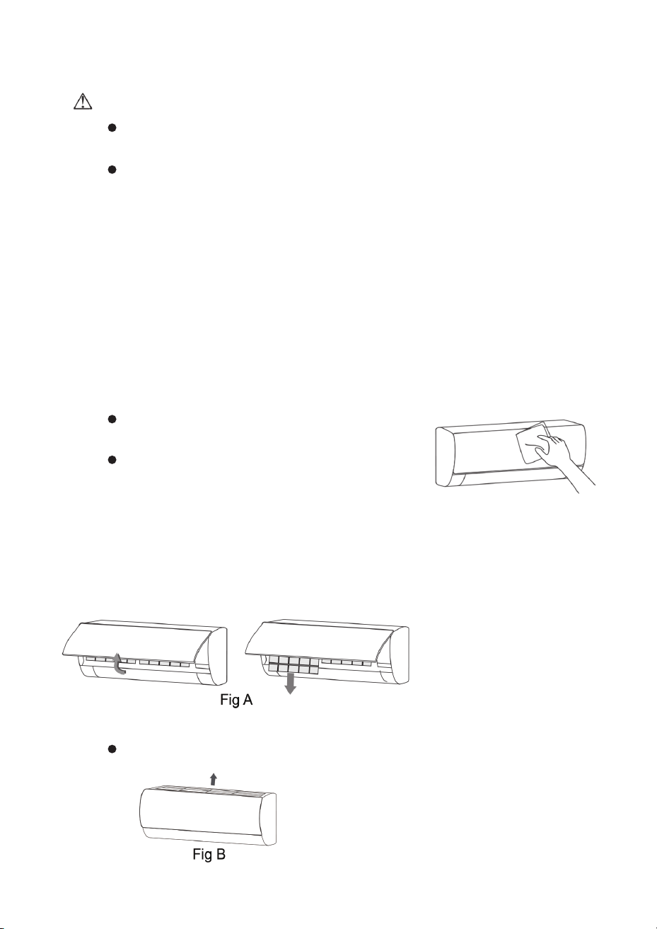
If the front panel is dirty, wipe it gently with a soft cloth
wrung out in lukewarm water (below 40°C / 104°F).
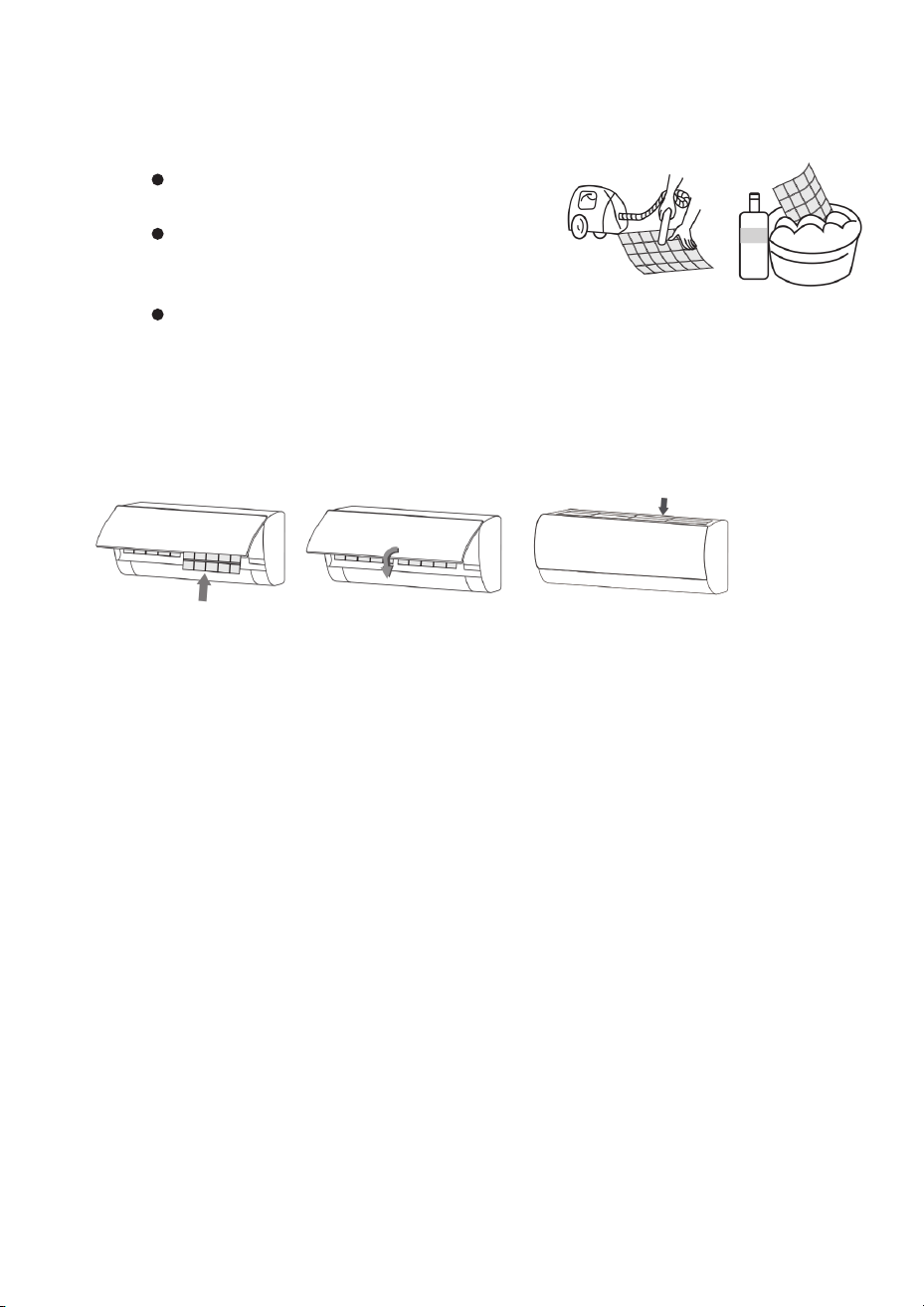
The air filter is located above the main body of the unit. Pull it upward to remove
it, as shown.
Do not wet or rinse the air conditioner with water. Water on electrical parts
can cause electric shock.
Do not remove the panel while cleaning.
Cleaning the Front Panel
Removing the Air Filter
Fig A type units
Fig B type units
1. Use both hands to open the front panel from both ends, following the direction
of the arrows.
2. Slide or lift the air filter out of its slot and remove it.
CLEAN AND CARE
19
Cleaning the Air Filter
Before Using the Air Conditioner
After Using the Air Conditioner (Seasonal Shutdown)
Use a vacuum cleaner or clean water to
remove dust from the filter.
If the filter is very dirty (for example, greasy),
wash it with warm water (below 45°C / 113°F)
and a mild detergent.
Shake off excess water and let the filter dry completely in the shade. Do not
expose it to direct sunlight or use heat sources to dry it.
Reinstalling the Air Filter
1. Once the filter is completely dry, reinstall it in the reverse order of removal.
1. Check that all air inlets and outlets on both indoor and outdoor units are clear
and not blocked.
1. Turn off the air conditioner, switch off the main power, and remove the remote
control batteries.
4. Check that fresh batteries are installed in the remote control and that they have
enough power.
4. Check the outdoor unit bracket again for any signs of damage and contact
service if needed.
5. Inspect the outdoor unit mounting bracket for damage. If damaged, contact
local service for inspection.
2. Check that the drain hose and drain outlet are not blocked. Clean if necessary.
2. Clean the air filter and wipe the unit housing.
3. Confirm that the ground wire is securely connected.
3. Remove dust and debris from around the outdoor unit. .
2. Make sure it is seated correctly, then close and lock the front panel.
Before you use the unit after a long stop:
If you will not use the unit for a long time:
TROUBLESHOOTING
20
CAUTION
Do not attempt to repair the air conditioner yourself. Incorrect repairs may
cause electric shock, fire, or explosion. Contact an authorized service center
for repairs.
Before calling for service, you can check the following items. This may save you
time and service costs.
Possible causes and checks
Common Issues and Checks
The air
conditioner
does not work
The unit will
not restart
immediately
after being
turned off
The unit
stops shortly
after it starts
There may be a power outage. → Wait until power is
restored.
The power plug may be loose. → Make sure the plug is
fully inserted into the outlet.
A fuse may have blown or the circuit breaker may
have tripped. → Replace the fuse or reset the breaker if
appropriate.
A timer may be set for future startup.→ Cancel the timer
or wait until the set time.
If you turn the unit back on right after turning it off, the
system may delay for 3–5 minutes to protect the
compressor. → This delay is normal.
The room may have already reached the set tempera-
ture. → This is normal operation.
A shutdown timer may be active. → Turn the unit back
on if you want continued operation.
In heating mode, the unit may be in defrost mode.
→ It will resume heating automatically when defrosting
is complete.
TROUBLESHOOTING
21
Possible causes and checks
Possible causes and checks
Common Issues and Checks
Unusual Sounds or Appearances
Air is
blowing,
but cooling/
heating
is poor
Sound
of running
water
Clicking sound
at startup or
shutdown
The indoor
unit blows
an unpleasant
odor
The air filter may be clogged with dust, or the inlet/outlet
may be blocked. The louver angle may be too small.
→ Clean the filter, remove obstructions, and adjust the
louvers.
You may hear a “hissing” or “gurgling” sound when the
unit or compressor starts or stops. → This is the sound of
refrigerant flowing and is normal.
Due to temperature changes, plastic panels and other
parts may expand or contract and make a slight
clicking sound. → This is normal and not a fault.
Doors or windows may be open, or an exhaust fan may
be running. → Close doors and windows and turn off
unnecessary exhaust fans.
On heating models with auxiliary electric heat, the
auxiliary heat may be off. → Turn on the auxiliary heating
function (if your model has it).
Mode, temperature, or fan speed may be set incorrectly.
→ Select the correct mode and adjust the set tempera-
ture and fan speed.
The air conditioner itself does not create odors. Smells
usually come from the room (furniture, cigarettes, pets,
etc.) and accumulate on the filter and inside the unit.
→ Clean the air filter. If your model has a cleaning
function, activate it.
TROUBLESHOOTING
22
Possible causes and checks
Unusual Sounds or Appearances
Indoor
unit makes
abnormal
sounds
Water
droplets on
the indoor
unit
Mist or
fog coming
from the
air outlet
Relay or fan starting and stopping can cause audible
clicks.
During defrosting, the flow of refrigerant reversing can
create noise. → These are normal operating sounds.
Heavy dust on the air filter may cause airflow noise to
change. → Clean the filters.
In “Strong” or “Turbo” fan mode, airflow noise will be
higher. → This is normal. If it is uncomfortable, reduce
the fan speed.
When the room humidity is high, moisture may
condense around the air outlet or on the panel. → This
is a normal physical phenomenon.
When indoor temperature and humidity are high,
cool air may cause visible mist near the outlet. → After
some time, as the room cools and dries, the mist will
disappear.
Operating for a long time in cooling mode with open
doors/windows can cause more condensation and
dripping. → Close doors and windows.
If the louvers are set to a very small angle, cold air
may blow directly onto the air inlet area, causing
condensation. → Increase the louver opening angle.
When to Stop Immediately and Call for Service
Stop using the air conditioner, turn off the power, and contact your local service
center immediately if:
You hear harsh, unusual noises or smell burning or other strange odors from
the unit. .
The power cord or plug becomes abnormally hot..
Any liquid or foreign object enters the unit or remote control.
The circuit breaker or safety device frequently trips.
Do not continue to operate the unit in these situations.
INSTALLATION NOTICES
23
Important Notice
Unpacking and Inspection
Safety Requirements for R32 Refrigerant Installation
If refrigerant leaks during installation:
Keep these items away from the area below the indoor unit:
This air conditioner must be installed by a qualified professional in accordance
with national electrical codes and this manual. Contact an authorized service
center before installation.
Open the carton in a well-ventilated area (open doors and windows) away
from any ignition sources.
R32 is a flammable refrigerant. Follow these safety precautions:
Before opening the outdoor unit box:
A leak test must be performed after installation.
Check for refrigerant leaks. Stop installation immediately if leakage is found.
Have fire safety equipment ready before starting.
Immediately measure the refrigerant concentration in the room until it reaches
a safe level.
Electrical appliances, power switches, outlets .
High-temperature heat sources.
Static-generating equipment ..
If leakage affects performance, stop work immediately, evacuate the system,
and return it to an authorized service station.
Keep the installation area well-ventilated (doors and windows open).
Installers must wear pure cotton clothing and gloves to prevent static discharge.
Keep a leak detector running during the entire installation.
No smoking, open flames, or phone use in areas where R32 refrigerant is present..
Have fire safety equipment ready before inspection.
Inspect refrigerant pipes for damage, dents, or collision marks.
To move the unit to a new location, contact your local authorized service center.
Note: Installers must wear anti-static equipment.
INSTALLATION NOTICES
24
Installation Location Requirements:
Install in an accessible location for service and maintenance.
Do not block air inlets or outlets.
Keep away from heat sources and flammable materials.
Connecting Lines
If the connecting line is not long enough during installation or repair, replace the
entire line with the original specification. Do not extend or splice the line.
Where to Install
Installation Site Inspection
Avoid these locations:
Before installing:
Installation best practices:
Areas with flammable or explosive gas leaks, or corrosive gases.
1. Check the outdoor unit nameplate to confirm the refrigerant type is R32.
3. R32 units must not be installed in enclosed spaces within a building.
2. Verify room size meets minimum requirements (see Page 2 refrigerant charge
table). The outdoor unit must be in a well-ventilated location.
4. Before drilling holes in walls, check for hidden water, electrical, or gas lines. Use
existing wall openings when possible.
Keep the connecting lines between indoor and outdoor units as short as possible.
Choose a location that is easy to service and has good ventilation.
Install the outdoor unit away from neighbors’ doors, windows, and plants.
Do not install the outdoor unit in aisles, stairways, exits, fire escapes, or other
public areas.
Areas with excessive noise or vibration.
Areas with strong electromagnetic fields.
Areas with heavy grease, sand, direct sunlight, or high heat..
Within reach of children.
INSTALLATION NOTICES
25
Mounting Bracket Requirements
The mounting bracket must meet national or industry standards for strength.
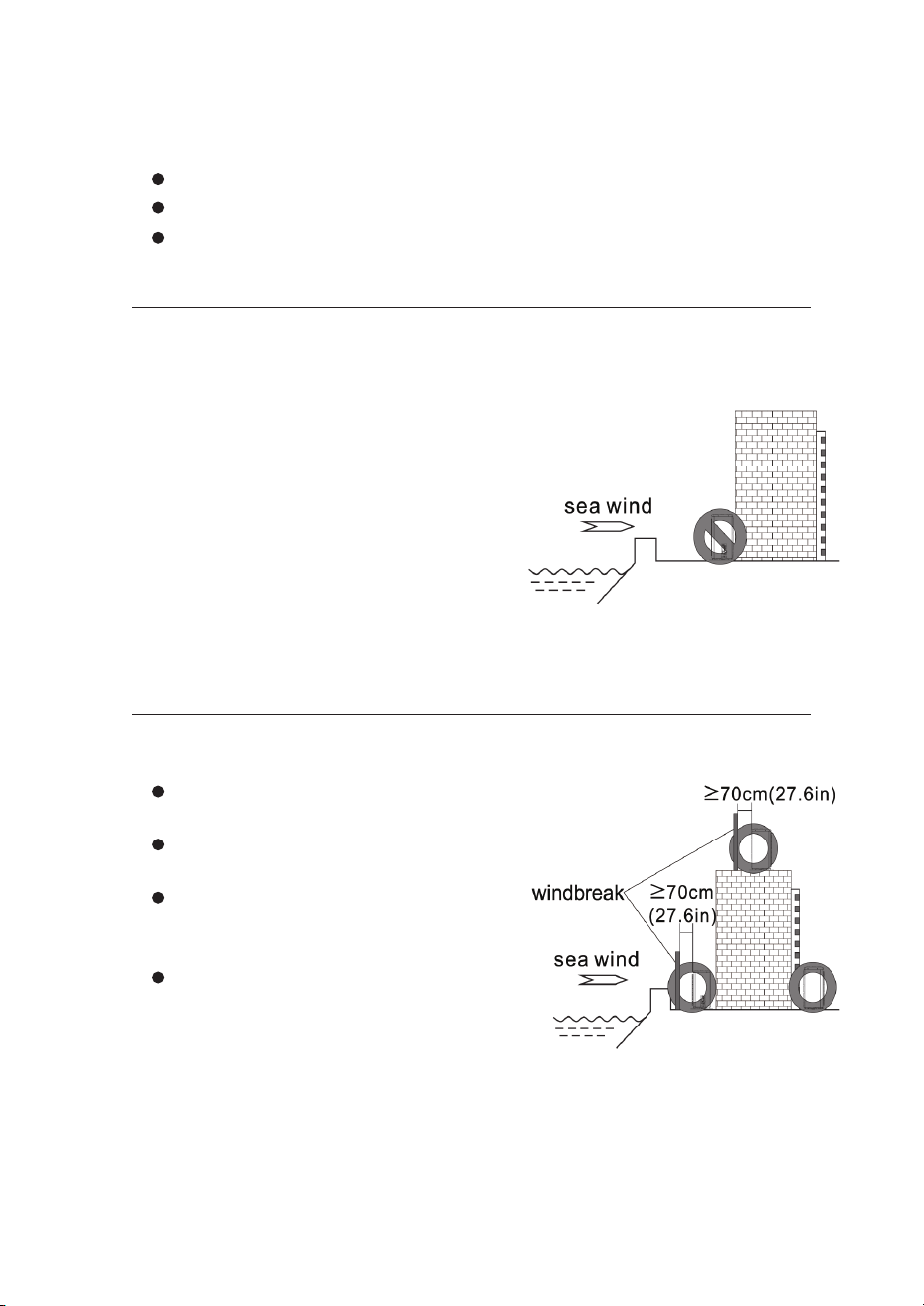
Install the outdoor unit on the side opposite
the sea wind, or install a windbreak.
The windbreak should be made of concrete
or similarly strong material.
Windbreak dimensions: Height and width
should be at least 150% of the outdoor
unit size.
Maintain at least 70 cm (27.6 in) clearance
between the outdoor unit and windbreak
for proper airflow.
Welded areas must be rust-proofed.
The bracket and mounting surface must support at least 4 times the weight
of the unit, or 200 kg (440 lbs), whichever is greater.
Installation Near the Coast
If installing near the ocean or salty air:
Windbreak Installation (Coastal Areas)
1. Do not install where corrosive gases (acid or alkaline) are present.
4. Choose a well-drained location.
2. Do not expose the unit to direct sea wind
(salt spray). Salt corrosion on the condenser
and evaporator fins can cause malfunction
or poor performance.
3. If the outdoor unit is near the coast, shield
it from direct sea wind or apply additional
anti-corrosion treatment to the heat
exchanger.
Maintenance: Clean dust and salt from the heat exchanger with water at least
once per year.
INSTALLATION NOTICES
26
Power Supply Requirements
UL Certification:
Use the rated voltage and a dedicated circuit for the air conditioner.
Power cable size must meet national electrical code requirements.
Operating voltage range: 90–110% of rated voltage. If voltage is unstable,
install a voltage regulator.
Maintain at least 1.5 m (4.9 ft) clearance between the air conditioner and any
combustible materials.
For units with maximum current ≥16A, install a circuit breaker or GFCI with
appropriate protection.
Cable Requirements (Compliance-Specific)
Wire Size Tables
The supply cord of appliances for outdoor use shall be between 1.5 (4.9 ft) and
3 m (9.8 ft) long and shall be either an EXTRA HARD USAGE or a HARD USAGE
CORD. (Only for the AC with UL or ETL-MARKING, UL60335-2-40)
Cable Types: Outdoor Power Cable: H07RN-F or H05RN-F; Interconnection cord:
H07RN-F or H05RN-F; (For the AC with CE-MARKING & CB-MARKING,
IEC 60335-2-40+A1:2016)
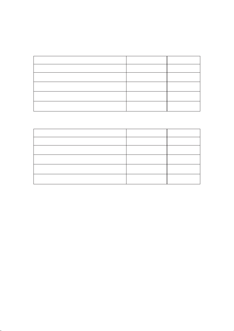
Circuit Amps (A) Recommended Wire Size (AWG)
<10
<13
<18
<25
<30
<40
<55
18
16
14
12
10
8
6
NOTE: To ensure safety, the wire diameter can be larger and smaller is prohibited.
VDE Certification:
Circuit Amps (A) Nominal Cross-Sectional Area (mm²)
6
<10
<16
<25
<32
<40
0.75
1.0
1.5
2.5
4
6
NOTE: To ensure safety, the wire diameter can be larger and smaller is prohibited.
NOTE: For the number of conductors needed, refer to the wiring diagram on the
unit you purchased.
INSTALLATION NOTICES
27
Cable Selection
The size of the interconnection cord, power cable, fuse, and circuit breaker
depends on the unit’s maximum current. Check the nameplate on the side panel
of the unit for the maximum current rating. Use this information to select the
correct cable, fuse, and breaker.
Means for disconnection must be incorporated in the fixed wiring in
accordance with the wiring rules.
Wear safety harnesses and use ropes strong enough to secure the outdoor unit.
Gas pipes
Lightning rods
This prevents falls that could cause serious injury, death, or property damage.
Water pipes
Telephone lines
Improperly grounded circuits
Working at Heights
Grounding Requirements
When installing at 2 m (6.6 ft) or higher above ground level:
Do NOT connect the ground wire to:
This air conditioner is a Class I electrical appliance and must be properly grounded.
The ground wire is for safety only and must not be used for other purposes or
fastened with standard screws.
All wiring connections must follow the wiring diagram attached to the unit. Fuse
ratings are printed on the circuit board or fuse sleeve.
INSTALLATION NOTICES
28
Use wire diameter recommended in this manual
Maintain 12 mm clearance between the auxiliary heater and the unit casing to
prevent fire hazards.
If the heater, PTC, or protection device is damaged, it must be replaced by a
qualified technician using manufacturer-supplied parts.
Terminal inner diameter must match screw size (no more than 4.2 mm / 0.17 in)
Use ring (O-type) terminals that meet local codes
After installation, verify all screws are tight with no risk of loosening
Interconnection cord requirements:
Safety Requirements:
Wiring and Fuse Information
NOTE: Only applicable to models with auxiliary heating part.
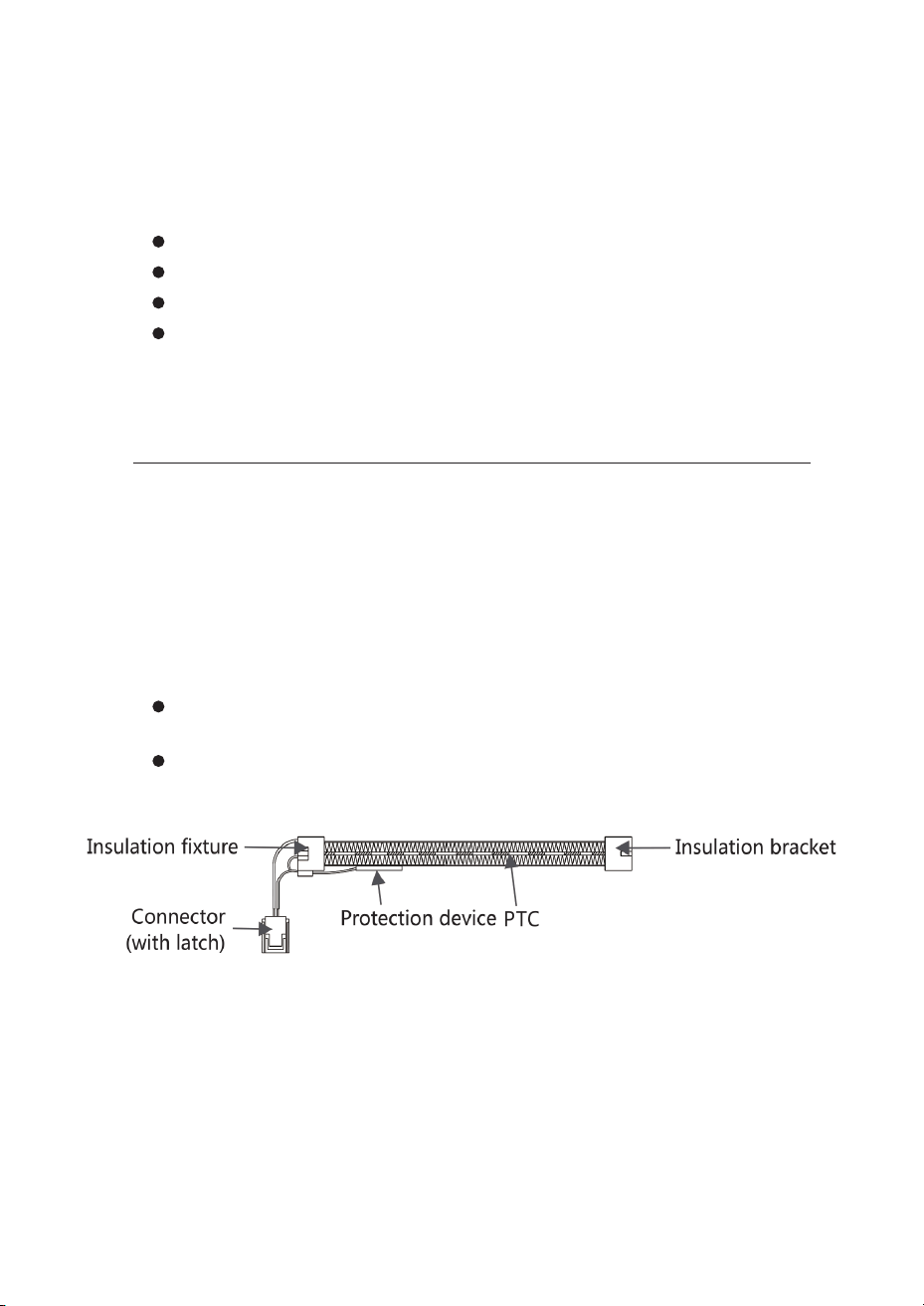
Auxiliary Electric Heating (Select Models Only)
The electric auxiliary heating components are ceramic PTC (Positive Temperature
Coefficient) elements installed inside the indoor evaporator. Input power is shown
on the nameplate under “Electric Heating Input Power” (some models may not
have this).
NOTE: This diagram is for reference only. Refer to your actual indoor unit.
INSTALLATION NOTICES
29
Packing List
Indoor Unit Package:
Outdoor Unit Package:
Item
Item
Quantity
Quantity
Unit
Unit
Indoor Unit
Outdoor Unit
Remote Controller (*)
Connecting Pipes (*)
Batteries AAA (*)
Plastic Strap (*)
Owner’s Manual
Pipe Protection Ring (*)
Drain Pipe (*)
Putty (*)
Set
Set
1
1
PC
PC
1
2
PC
Roll
2
1
Set
PC
1
1
PC
Packet
1
1
NOTE: Optional parts (*) - some models may not include these items.
Interconnection cord and sound-dampening pads are optional accessories.
Actual contents may vary.
INDOOR UNIT INSTALLATION
30
Installation Clearances
Mounting the Wall Bracket
Drilling the Wall Hole
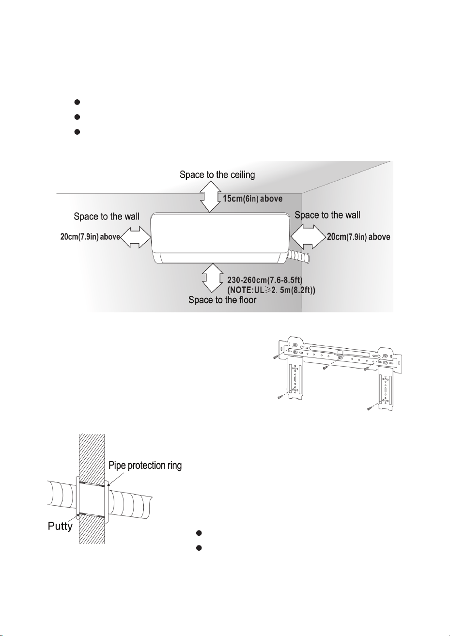
Maintain the following clearances around the indoor unit:
Distance from ceiling: At least 15 cm (6 in)
Protect pipes and cables from damage
Prevent rodents from entering through the wall cavity
Height above floor: 230-260 cm (7.6-8.5 ft)
Distance from side walls: At least 20 cm (7.9 in) on each side
NOTE: For UL certified units, install at least 2.5 m (8.2 ft) above floor
NOTE: Wall hole diameter is typically 60-80 mm. Check for hidden electrical
wiring and avoid solid structures when drilling.
1. Choose a solid wall that can support the unit
without vibrating.
1. Drill a hole at the predetermined location using a
hammer drill or core drill.
2. Install the mounting bracket horizontally on
the wall using Phillips-head screws. Use a level
to ensure it is perfectly horizontal and vertical.
2. Angle the hole 5-10° downward toward the
outside so condensate drains properly.
3. Pull firmly on the bracket after installation to
confirm it is securely mounted.
3. Install a pipe protection ring and seal it with
putty to:
INDOOR UNIT INSTALLATION
31
Routing the Pipes
Connecting the Refrigerant Pipes
Connecting the Refrigerant Pipes
Tightening Torque Table
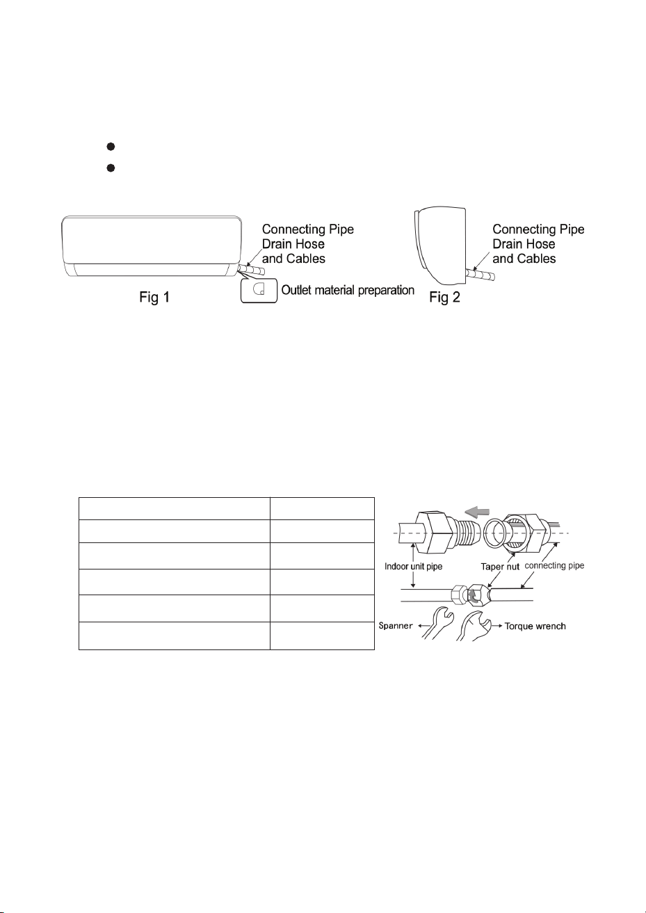
Depending on your installation, pipes can be routed:
For sideways routing: Cut off the knockout panel on the unused side.
Sideways from the left or right (Fig 1)
Vertically from the back (Fig 2)
1. Remove the factory pipe caps from the indoor unit. Hand-tighten the flare nut onto
the connection.
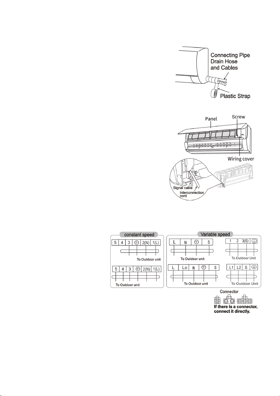
1. Wrap the connection joint between the indoor unit and refrigerant pipe with
insulation sleeve.
2. Seal all insulation to prevent condensation from forming on the connection.
3. Connect the drain hose to the drain outlet and straighten all pipes and cables.
4. Bundle the pipes, cables, and drain hose together using plastic cable ties.
Make sure the drain hose slopes downward.
2. Align the pipe carefully, then finger-tighten the flare nut. Use a torque wrench to
tighten to the specified torque.
Important: Inspect flare connections for damage before installation. Do not reuse
flare connections unless you re-flare the pipe.
Important: If your unit uses quick connectors, refer to the separate quick
connector installation guide.
Pipe Size (mm / in) Torque (N·m)
Φ6 / Φ6.35 (1/4)
Φ9 / Φ9.52 (3/8)
Φ12 / Φ12.7 (1/2)
Φ15.88 (5/8)
Φ19.05 (3/4)
15-25
35-40
45-60
73-78
75-80
Mounting the Indoor Unit
Connecting Wiring to the Indoor Unit
Wiring Diagrams (Examples)
INDOOR UNIT INSTALLATION
32
1. Hang the indoor unit on the wall bracket. Move it left
and right to ensure the hooks are properly seated.
1. Open the front panel and remove the screw from the wiring
cover. Take off the cover.
4. Replace the wiring cover and tighten the screw.
5. Close the front panel.
2. Route the interconnection cord through the cable
passage hole at the back of the indoor unit and pull
it out from the front.
3. Remove the wire clip. Connect the interconnec
tion cord to the terminal block according to the
wiring diagram. Tighten the terminal screws and
secure the cord with the wire clip.
2. Push the unit firmly toward the wall until
the hooks click into place.
NOTE: Some models do not have a signal cable.
NOTE: This manual includes wiring diagrams
for several air conditioner types. If your specific
model’s wiring diagram is not shown, refer to the
wiring diagram attached to your unit.
Constant Speed Models:
Variable Speed Models:
Models with Connector:
Terminals: 5 4 3 2(N) 1(L)
Connect to outdoor unit
Terminals: L N S or 1 2 3(S)
Connect to outdoor unit
If a quick-connect plug is
present, simply plug it in.
After Installation - Check These Items:
1. Terminal screws are tight with no risk of loosening.
3. Control box cover is securely closed.
2. Display board connector is positioned correctly and not touching the terminal block.
OUTDOOR UNIT INSTALLATION
33
Outdoor Unit Installation Clearances
Connecting Refrigerant Pipes to the Outdoor Unit
Mounting Bolt Spacing
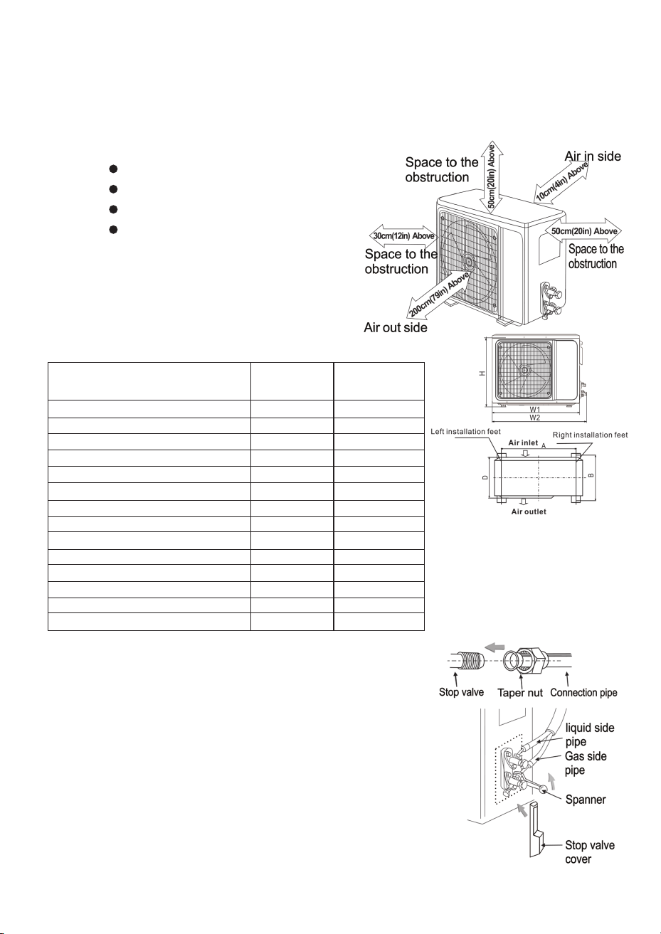
Maintain the following minimum clearances around the outdoor unit for proper
airflow and service access:
Use the table below to determine the
correct mounting bolt spacing
(dimensions A and B) for your outdoor unit:
Above the unit: At least 200 cm (79 in)
On each side: At least 30 cm (12 in)
In front (air outlet side): At least 50 cm (20 in)
Behind (air inlet side): At least 10 cm (4 in)
Outdoor Unit Size
W(D)×H×D (mm/in)
Dimension A
(mm/in)
Dimension B
(mm/in)
665(710)×420×280 (26.2(28.0)×16.5×11.0) 430 (16.9) 280 (11.0)
750(880)×545×285 (29.5(34.6)×21.5×11.2) 480 (18.9) 283 (11.1)
970(1044)×805×395 (38.2(41.1)×31.7×15.6) 675 (26.6) 410 (16.1)
790(780)×545×285 (31.1(30.7)×21.5×11.2) 540 (21.3) 280 (11.0)
785(845)×555×300 (30.9(33.3)×21.9×11.8) 546 (21.5) 316 (12.4)
950(1044)×985×395 (37.4(41.1)×38.8×15.6) 610 (24.0) 388 (15.3)
660(710)×500×240 (26.0(28.0)×19.7×9.4) 500 (19.7) 260 (10.2)
800(880)×545×315 (31.5(34.6)×21.5×12.4) 545 (21.5) 315 (12.4)
940(1010)×1320×370 (37.0(39.8)×52.0×14.6) 625 (24.6) 364 (14.3)
840(880)×545×315 (33.1(34.6)×21.5×12.4) 545 (21.5) 315 (12.4)
900(960)×700×360 (35.4(37.8)×27.6×14.2) 632 (24.9) 352 (13.9)
709(761)×538×280 (27.9(30.0)×21.2×11.0) 480 (18.9) 283 (11.1)
825(880)×555×335 (32.5(34.6)×21.9×13.2) 540 (21.3) 335 (13.2)
650(703)×455×233 (25.6(27.7)×17.9×9.2) 460 (18.9) 253 (10.0)
Follow these steps to connect the refrigerant lines:
1. Align the connecting pipe with the center of the stop
valve port on the outdoor unit.
2. Hand-tighten the flare nut onto the valve connection.
3. Use a torque wrench to tighten the connection to
the specified torque value (see torque table on page 22).
4. Check all connections to ensure screws and fittings
are secure with no risk of loosening.
OUTDOOR UNIT INSTALLATION
34
Refrigerant Charge Adjustment
Refrigerant Adjustment Guidelines:
Important Installation Notes
Follow these steps to wire the outdoor unit:
Wiring Connection
If the pipe length is changed from the standard length, you may need to add or
remove refrigerant to maintain proper system performance.
Connection Pipe Length Refrigerant Adjustment Amount of Refrigerant in Unit
≤5 m (16.4 ft)
>10 m (32.8 ft)
5-10 m (16.4-32.8 ft)
≤1 Kg
≤1 Kg
≥2 Kg
-
R32=1200BTU: Reduce 20g/m
R32=1200BTU: Add 15g/m
R32=1800BTU: Reduce 40g/m
R32=1800BTU: Add 25g/m
No adjustment needed
NOTE: This table is for reference only.
Do not reuse flare connections unless the pipe has been re-flared.
Verify all connection screws are tight and properly secured.
IMPORTANT: If your unit uses quick connectors, refer to the separate quick
connector installation booklet.
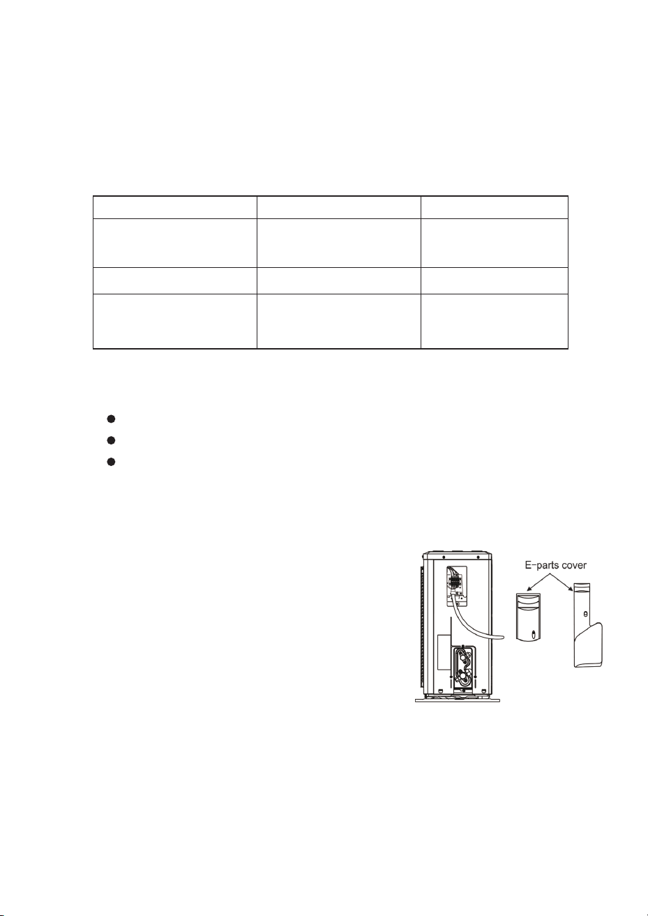
1. Loosen the screws and remove the electrical box
cover from the outdoor unit.
2. Connect the cables to the corresponding
terminals on the terminal board according to the
wiring diagram. If there are signal wires connected to
the plug, simply connect the plug.
3. Ground wire installation: Remove the grounding screw
from the electrical box, attach the grounding wire end to
the grounding screw, and reinstall the screw into the
grounding hole.
4. Secure the cable with the cable clamp (pressing board).
5. Replace the electrical box cover in its original position and
secure it with the screws.
OUTDOOR UNIT INSTALLATION
35
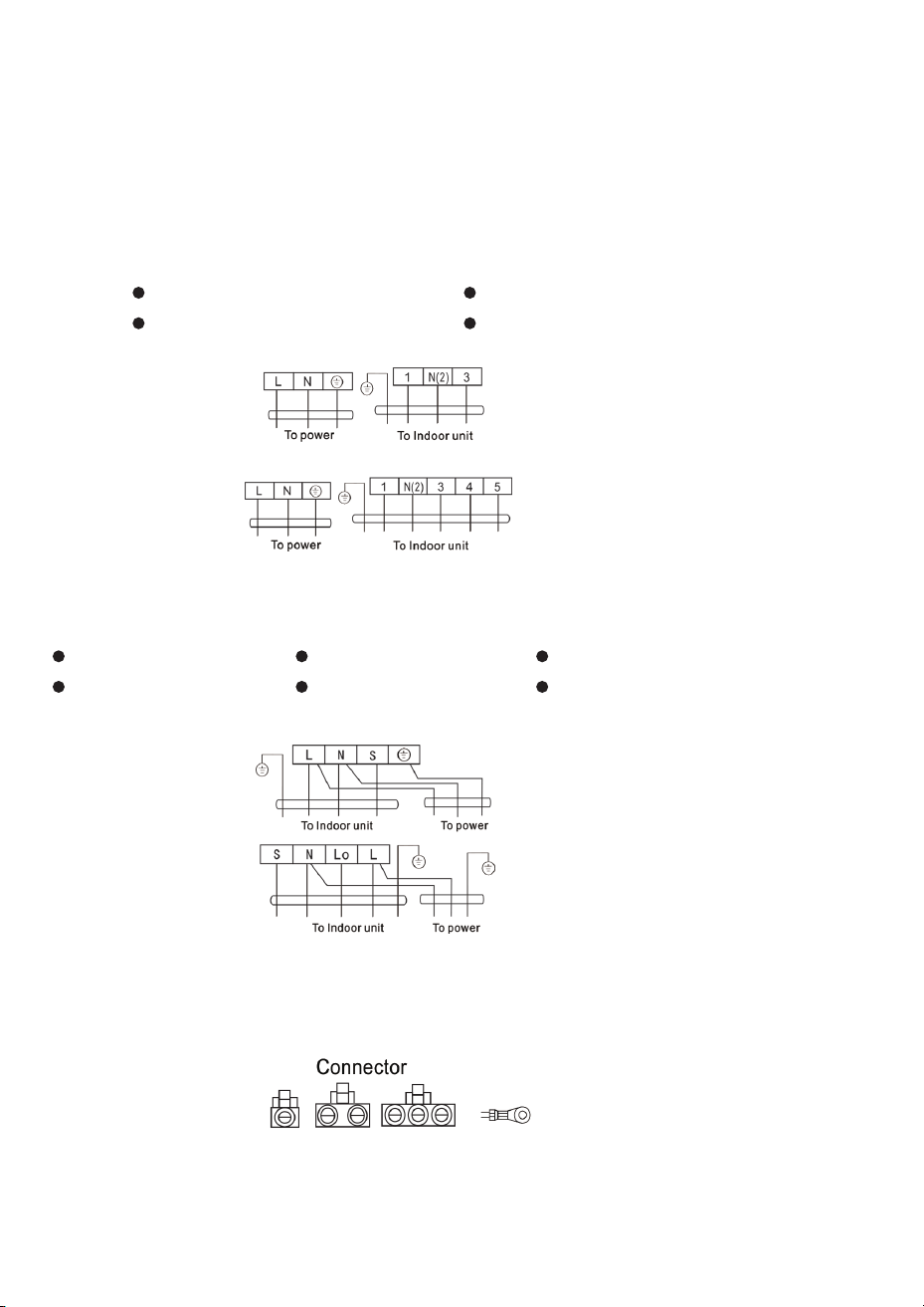
Wiring Diagram
Constant Speed Models
Units with Quick-Connect Plug
Constant Speed
Variable Speed Models
Variable Speed
Use the appropriate wiring diagram for your unit type:
Configuration 1:
Connector Options:
Standard Configuration:
Configuration 2:
Alternate Configuration: With Multiple Connections:
Terminals: L | N | ⏚
If your unit has a connector plug, simply plug it in directly.
If there is a connector, connect it directly.
Terminals: L | N | S | ⏚
Connect to power and indoor
unit as shown
Connect to indoor unit
and power as shown
Connect to power and indoor
unit as shown
Connect to indoor unit
and power as shown
Connect to indoor unit
and power as shown
Terminals: L | N | ⏚ and 1 | N(2) | 3
Terminals: S | N | Lo | L Terminals: L | N(2) | 3 | 4 | 5 and S | N | Lo | L
OUTDOOR UNIT INSTALLATION
36
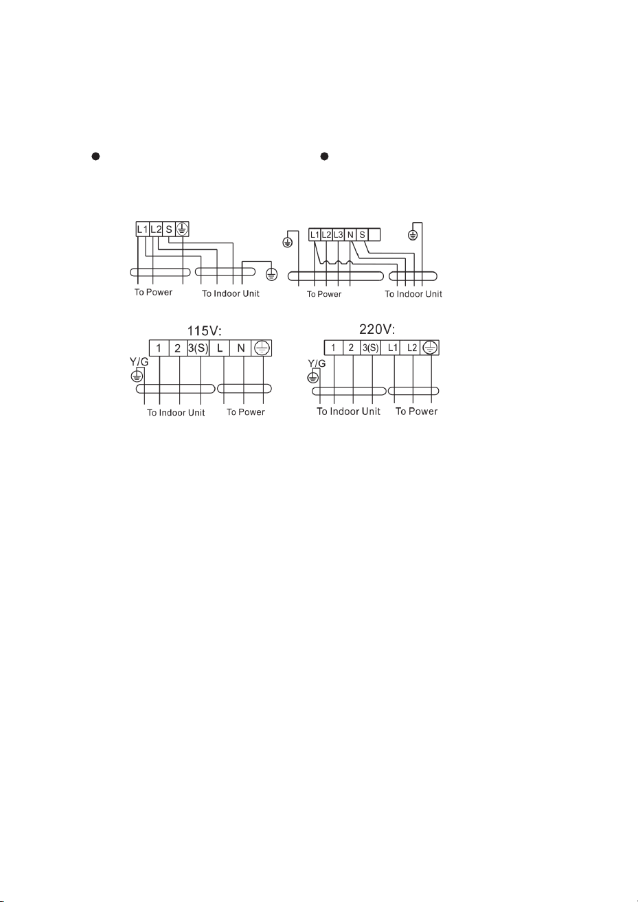
Voltage-Specific Wiring (Variable Speed)
115V Configuration: 220V Configuration:
Terminals: L | T2 | N(S) | L | N | ⏚
Connect to indoor unit and
power as shown
Connect to indoor unit and
power as shown
Terminals: L | T2 | N(S) | L(1) | 2 | ⏚
NOTE: This manual includes wiring diagrams for different air conditioner types.
If your specific model’s wiring diagram is not shown here, refer to the wiring
diagram label attached to your actual unit.
NOTE: This manual includes wiring diagrams for different types of air conditioners.
We cannot guarantee that all specialized wiring configurations are included.
The diagrams shown are for reference only. If your unit’s wiring is different from
these diagrams, refer to the detailed wiring diagram label attached to your
specific unit.
OUTDOOR UNIT INSTALLATION
37
★ An R32-rated vacuum pump must be used for R32 refrigerant systems.
Before starting work on the air conditioner:
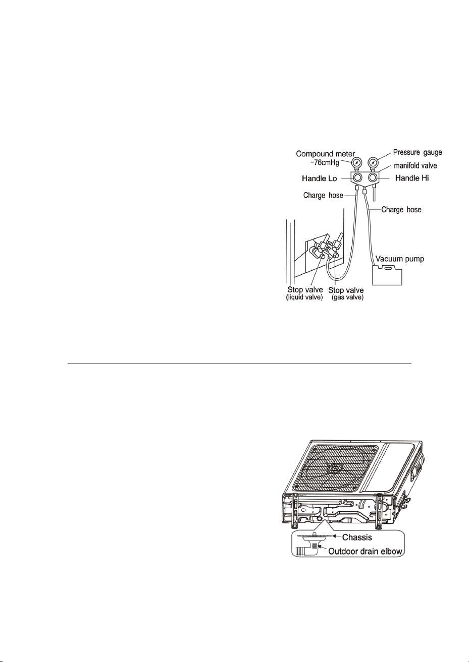
To install the outdoor drain elbow:
For units with heating capability:
When the unit is in heating mode, condensing water and defrost water can drain
reliably through the drain hose installation.
Vacuuming (Evacuating the System)
Vacuuming (Evacuating the System)
1. Remove the covers from the stop valves (gas valve
and liquid valve) and ensure you tighten all
connections properly to prevent air leakage
1. Drill a Φ25 mm (1 in) hole in the base plate of the
outdoor unit.
2. Attach the drain hose to the elbow so that
wastewater from the outdoor unit can drain out
to a proper drainage location.
4. Fully open the handle Lo of the manifold valve
and run the vacuum pump for at least 15 minutes.
Verify that the compound vacuum gauge r
eads -0.1 MPa (-76 cmHg).
2. To prevent air leakage and spilling, tighten all
connecting nuts on all flare tubes.
5. After the vacuum process, fully open the stop
valve with a hex wrench.
6. Check that both indoor and outdoor connections
are free of air leakage.
3. Connect the stop valve, charge hose, manifold
gauge, and vacuum pump as shown in the diagram.
IMPORTANT: Units with quick connectors do not require vacuum pumping.
CHECK AFTER INSTALLATION AND TEST OPERATION
38
Check After Installation
Check After Installation
Test Operation Method:
★ Electricity Safety Check
★ Installation Safety Check
★ Refrigerant Leak Test
1. Verify that the supply voltage meets the unit’s requirements.
1. Turn on the power and press the ON/OFF switch button on the remote controller to
start the air conditioner.
2. Select COOL, HEAT (not available on cool-only models), SWING, and other opera-
tion modes with the remote controller and verify that the operation functions correctly.
1. Verify that all piping is secure.
Depending on the installation method, use one of the following methods to check for
leaks, particularly at the four connections on the outdoor unit and the connection points
of valves:
2. Check for loose or missing connections in the power, signal, and grounding wires.
2. Check that the condensate drain flows smoothly.
3. Confirm that the ground wire of the air conditioner is securely grounded.
3. Verify that all wiring and piping are correctly installed.
4. Make sure no foreign materials or tools are left inside the unit. .
5. Check the refrigerant pipeline for signs of damage.
Method 1 - Bubble Method:
Test Operation Preparation:
Method 2 - Instrument Method:
Apply a uniform layer of soapy water over the suspected leak area and observe
carefully for bubbles.
Before starting the test, verify the following:
Use a leak detector by pointing the probe at the leak area according to the
detector’s instructions.
NOTE: Make sure the area is well-ventilated before checking for leaks.
All wiring and connection cables are properly connected.
The valves on the gas side and liquid side are fully open.
The power cable is connected to an independent power outlet..
Batteries are installed in the remote control.
The area is well-ventilated before testing.
MAINTENANCE NOTICE
39
Attention:
Qualification Requirements for Maintenance Personnel
Operating Procedures
For maintenance or repair, contact authorized service centers.
Maintenance by unqualified personnel may cause serious safety hazards.
This manual focuses on special maintenance requirements for R32 refrigerant
appliances.
Ask the manufacturer or refer to the detailed service handbook for detailed
information.
An individual authorized to work on refrigeration equipment containing R32 refrigerant
must be properly trained. This training must be conducted by nationally recognized
training organizations that are accredited to teach the relevant national competency
standards established by law or regulation. Proof of completed training should be
documented by a certificate.
All maintenance staff and others working in the immediate area must be informed
about the nature of the work being performed. Work should be conducted in a
controlled area. The area around the workspace must be cordoned off. Ensure that
conditions in the work area remain safe by limiting access to qualified personnel only.
Maintenance and repair must be conducted according to the manufacturer’s recom-
mended methods. If professionals other than the manufacturer’s technicians are need-
ed to help maintain and repair the equipment, they must work under the supervision
of individuals qualified to repair equipment containing flammable refrigerant. .
A safety inspection must be performed before working on equipment with R32
refrigerant to minimize the risk of fire. Check whether the installation location is
well-ventilated and whether the fire prevention equipment is in good working
condition. While maintaining the refrigeration system, follow these precautions before
starting work:
Refer to the service handbook for R32 refrigerant when maintaining or repairing
R32 air conditioner units.
1. Special Training Required for Refrigerant Enforcement
1. General Work Area:
2. Maintenance and Repair of Equipment
Inspection of the Site
MAINTENANCE NOTICE
40
2. Checking for Refrigerant Presence:
3. Presence of Fire Extinguisher:
5. Ventilated Area (Keep Doors and Windows Open):
6. Checks on Refrigeration Equipment:
4. No Ignition Sources:
Before beginning any work, check the area with an appropriate refrigerant detector.
This ensures the technician is aware of any potentially toxic or flammable atmo-
spheres. Make sure the leak detection equipment being used is suitable for R32 and is
properly maintained with adequately sealed or intrinsically safe components.
If hot work (welding, brazing, etc.) will be performed on the refrigeration equipment or
any associated components, appropriate fire extinguishing equipment must be readily
available. Keep a dry powder or CO2 fire extinguisher near the work area.
Before beginning work, ensure the area is open and adequately ventilated. Ventilation
must continue throughout the work period. Proper ventilation safely disperses any
released refrigerant and prevents it from accumulating in the atmosphere.
When replacing electrical components, verify they are suitable for the intended
purpose and meet the correct specifications. Always follow the manufacturer’s
maintenance and service guidelines. Contact the manufacturer’s technical support
department if you have questions. The following safety checks must be performed
when working with flammable refrigerants:
Do not perform any work on a refrigeration system that involves exposing refrigerant
piping without ensuring that all ignition sources are eliminated. This includes welding
torches, open flames, portable heating equipment, and smoking. All possible ignition
sources must be kept far enough away from the installation site, as well as from any
area where refrigerant may be released into the surrounding space during installation,
repair, or disposal. Prior to starting work, inspect the area around the equipment to
verify there are no flammable materials or ignition sources. Post “No Smoking” signs at
the work location.
Verify that the charge size is appropriate for the room size in which the refriger-
ant-containing components are installed.
Confirm that ventilation machinery and outlets are operating adequately and
are not obstructed.
If using an indirect refrigeration circuit, check that the secondary circuit has been
inspected for refrigerant presence.
Ensure refrigerant components or connections are installed in a location where
they are unlikely to be exposed to any substance that may corrode refriger-
ant-containing components. If using components made of materials that are
inherently resistant to corrosion or are suitably protected against corrosion, this
check may be omitted.
MAINTENANCE NOTICE
41
7. Checks on Electrical Equipment:
Leak Detection Method:
Inspection of Cable
Leakage Check of R32 Refrigerant
Initial Safety Checks Include:
Repair and maintenance of electrical components must include initial safety checks
and proper component inspection procedures. If a fault could compromise safety,
disconnect the electrical supply from the circuit until repairs are complete. If the fault
cannot be corrected immediately but continued operation is necessary, use an
adequate temporary solution. This should be reported to the owner of the equipment
so all parties are aware of the condition.
For systems with R32 refrigerant, an electronic leak detection instrument is available to
detect and locate leaks. Leak detection should not be conducted in an environment
with refrigerant present. Make sure the leak detector is fully powered (with external
ignition source) and is suitable for the refrigerant being used. Set the detector to detect
the minimum ignitable fuel concentration (percentage) of the refrigerant. Calibrate and
adjust the detector to the proper gas concentration (no more than 25%) using the gas
type being serviced.
The fluid used in leak detection must be suitable for most refrigerants. Do not use
chlorine-based solvents, as they may react with the refrigerant and cause corrosion of
copper piping.
If gas leakage is detected, remove all fire sources from the scene or extinguish any
open flames. If a leak requiring brazing is found, all refrigerants must be recovered,
isolated, or evacuated away from the leak site (using suitable valving) before and
during welding. Use only dry nitrogen during the welding process.
Check cables for wear, corrosion, overvoltage, vibration, and sharp edges or other
adverse effects from the surrounding environment. During inspection, consider the
impact of aging on the continuous vibration of the compressor and fan.
NOTE: Check for leaks in an environment where there is no potential ignition source.
Do not use halogen probes or any other detector that uses an open flame.
Verify that capacitors are discharged in a safe manner to avoid sparking.
Maintain continuity of grounding (earthing).
Confirm that no live electrical components or wiring are exposed while charging,
recovering, or purging the system.
MAINTENANCE NOTICE
42
Removal and Vacuum Pumping
Procedures of Charging Refrigerants
1. Verify there is no ignition source near the outlet of the vacuum pump and that
ventilation is adequate.
2. Allow the maintenance and other operations of the refrigeration circuit to
proceed according to standard procedures. However, the following best
practices regarding flammability must always be kept in mind. You should follow
these safety procedures:
3. The refrigerant should be returned to the appropriate storage tank. The
system should be blown with oxygen-free nitrogen to ensure safety. This process
may need to be repeated several times. Do not perform this operation using
compressed air or oxygen.
4. Purging with Nitrogen:
Through the purging process, the system is charged with anaerobic nitrogen to
reach the working pressure under which work can be performed. After purging,
nitrogen is released to the atmosphere, and the system is evacuated to clear any
remaining gas. Repeat this process until all refrigerants in the system are removed.
After the refrigerant is evacuated, break the vacuum by releasing gas into the
atmosphere under pressure, then the system can be welded. This operation is
necessary for welding the pipeline.
In addition to the general procedure, the following requirements must be followed:
Remove the refrigerant.
Decontaminate the pipelines by purging with inert gases.
Ensure that contamination between different refrigerants does not occur when
using a refrigerant charging device. The pipeline for charging refrigerants should
be as short as possible to reduce the amount of residual refrigerants in it.
Storage tanks should remain vertically upright.
Do not overcharge refrigerants.
Verify that all purging solutions have been used before charging the
refrigeration system.
After finishing the charging process (or when it is not yet complete),
label the system with the appropriate markings.
Evacuate the system.
Decontaminate the pipeline again by purging with inert gases.
Open the system by cutting or brazing.
MAINTENANCE NOTICE
43
Scrap and Recovery
Scrap:
Safety Procedures:
Before performing this procedure, the technical personnel must be thoroughly familiar
with the equipment and all its features, and must adopt a recommended practice for
refrigerant-safe recovery. For recycling the refrigerant, analyze the refrigerant and oil
samples before disposal. Ensure power is available before starting work.
NOTE: The identification label should be made after the appliance is scrapped and
refrigerants are evacuated. The identification label should indicate that the appliance
has been scrapped and that the flammable refrigerant has been removed. This reflects
that the appliance can safely contain flammable refrigerants.
1. Be familiar with the equipment and its operation.
2. Disconnect power before beginning work.
3. Before carrying out this process, ensure the following:
6. Before starting recovery, verify that the storage tank has sufficient capacity.
8. Do not fill the tank to full capacity (the liquid injection volume must not exceed 80%
of the tank volume).
9. Even if the saturation is short, it must not exceed the maximum working pressure of
the tank.
10. After the completion of the tank filling and the end of the operation process, verify
that the tanks and equipment are removed quickly and all closing valves in the
equipment are closed.
11. The recovered refrigerants are not allowed to be injected into another system be
fore being purified and tested.
7. Start and operate the recovery equipment according to the manufacturer’s
instructions.
4. If possible, the refrigerating system should be vacuumed.
5. Even if the vacuum cannot be achieved, extract the refrigerant from each part of
the system as completely as possible.
The area is well-ventilated.
All personal protective equipment (PPE) is effective and can be used correctly.
The whole recovery process should be carried out under the supervision of
qualified personnel.
The recovery equipment and storage tank comply with all relevant national
standards.
All necessary mechanical equipment operation is properly facilitated.

MAINTENANCE NOTICE
44
Records:
1. The clearance of refrigerants in the system is required when repairing or
scrapping the appliance. It is recommended to completely remove the
refrigerant from the appliance to ensure safety.
2. Sampling is required prior to starting work on the refrigeration circuit or storage
tank. Verify that the capacity of the tank is appropriate for the refrigerant
injection quantity being used. All tanks intended for use in the recovery of
refrigerants should have a refrigerant identification label (e.g., refrigerant
recovery tank). Storage tanks should be equipped with pressure relief valves.
3. The recovered refrigerant, whether recycled or not, should be returned to
storage tanks. The tanks should be evacuated and maintained at room
temperature before use.
4. The recovery equipment should be kept in a good working condition and
equipped with operational instructions for easy access. The equipment should
be suitable for recovering various refrigerants and have on-site residues that
can be safely stored. Only use hoses and assembly apparatus which can be
normally used. The hose should be linked with detachable connection joints or
zero-leakage valves and be kept in a good condition.
5. Before using the recovery equipment, check that it is in good condition and
properly maintained. If electrical components are sealed to prevent electrical
damage, verify they are not adversely affected or damaged by wear. If you
have any questions, consult the manufacturer.
6. If the recovered refrigerant is loaded into a cylinder attached with a
transporting instruction, return it to the refrigerant manufacturer. Do not mix
refrigerant types in recovery equipment or storage tanks.
7. The space loading R32 refrigeration cannot be enclosed in the process of
transportation. Take all electrostatic measures if necessary during
transportation. In the process of transport, loading, and unloading, necessary
protective measures must be taken to protect the air conditioner to ensure it
meets national air-conditioning standards that apply when used.
8. When removing the compressor or clearing the compressor oil, verify that the
compressor is pumped to an appropriate level to ensure there is no residual
R32 refrigerant in the lubricating oil. Vacuum pumping should be carried out
before the compressor is returned to the supplier. Ensure that you are not
discharging oil from the system.


ELECTROLUX is a pending or registered trademark used under license
from AB Electrolux (publ).